service automation and - lagout · service automation and dynamic provisioning ... and product...
TRANSCRIPT


SERVICE AUTOMATION ANDDYNAMIC PROVISIONINGTECHNIQUES IN IP/MPLSENVIRONMENTS

WILEY SERIES IN COMMUNICATIONS NETWORKING & DISTRIBUTEDSYSTEMS
Series Editor: David Hutchison, Lancaster University, Lancaster, UK
Series Advisers: Serge Fdida, Universite Pierre et Marie Curie, Paris, France
Joe Sventek, University of Glasgow, Glasgow, UK
The ‘Wiley Series in Communications Networking & Distributed Systems’ is a series of
expert-level, technically detailed books covering cutting-edge research, and brand new
developments as well as tutorial-style treatments in networking, middleware and software
technologies for communications and distributed systems. The books will provide timely
and reliable information about the state-of-the-art to researchers, advanced students and
development engineers in the Telecommunications and the Computing sectors.
Other titles in the series:
Wright: Voice over Packet Networks 0-471-49516-6 (February 2001)
Jepsen: Java for Telecommunications 0-471-49826-2 (July 2001)
Sutton: Secure Communications 0-471-49904-8 (December 2001)
Stajano: Security for Ubiquitous Computing 0-470-84493-0 (February 2002)
Martin-Flatin: Web-Based Management of IP Networks and Systems,
0-471-48702-3 (September 2002)
Berman, Fox, Hey: Grid Computing. Making the Global Infrastructure a Reality,
0-470-85319-0 (March 2003)
Turner, Magill, Marples: Service Provision. Technologies for Next Generation
Communications 0-470-85066-3 (April 2004)
Welzl: Network Congestion Control: Managing Internet Traffic 0-470-02528-X (July 2005)
Raz, Juhola, Serrat-Fernandez, Galis: Fast and Efficient Context-Aware Services
0-470-01668-X (April 2006)
Heckmann: The Competitive Internet Service Provider 0-470-01293-5 (April 2006)
Dressler: Self-Organization in Sensor and Actor Networks 0-470-02820-3 (November 2007)
Berndt: Towards 4G Technologies: Services with Initiative 978-0-470-01031-0 (March 2008)

SERVICE AUTOMATIONAND DYNAMICPROVISIONINGTECHNIQUES IN IP/MPLSENVIRONMENTS
Christian Jacquenet, Gilles Bourdon and Mohamed Boucadair
All at
France Telecom, France

Copyright # 2008 John Wiley & Sons Ltd, The Atrium, Southern Gate, Chichester,
West Sussex PO19 8SQ, England
Telephone (þ44) 1243 779777
Email (for orders and customer service enquiries): [email protected]
Visit our Home Page on www.wiley.com
All Rights Reserved. No part of this publication may be reproduced, stored in a retrieval system or transmitted
in any form or by anymeans, electronic, mechanical, photocopying, recording, scanning or otherwise, except under the terms
of the Copyright, Designs and Patents Act 1988 or under the terms of a licence issued by the Copyright
Licensing Agency Ltd, 90 Tottenham Court Road, London W1T 4LP, UK, without the permission in writing
of the Publisher. Requests to the Publisher should be addressed to the Permissions Department, JohnWiley & Sons Ltd, The
Atrium, SouthernGate, Chichester,West Sussex PO19 8SQ, England, or emailed to [email protected], or faxed to (þ44)
1243 770620.
Designations used by companies to distinguish their products are often claimed as trademarks. All brand names
and product names used in this book are trade names, service marks, trademarks or registered trademarks
of their respective owners. The Publisher is not associated with any product or vendor mentioned in this book.
All trademarks referred to in the text of this publication are the property of their respective owners.
This publication is designed to provide accurate and authoritative information in regard to the subject matter covered. It is
sold on the understanding that the Publisher is not engaged in rendering professional services. If professional advice or other
expert assistance is required, the services of a competent professional should be sought.
Other Wiley Editorial Offices
John Wiley & Sons Inc., 111 River Street, Hoboken, NJ 07030, USA
Jossey-Bass, 989 Market Street, San Francisco, CA 94103-1741, USA
Wiley-VCH Verlag GmbH, Boschstr. 12, D-69469 Weinheim, Germany
John Wiley & Sons Australia Ltd, 42 McDougall Street, Milton, Queensland 4064, Australia
John Wiley & Sons (Asia) Pte Ltd, 2 Clementi Loop #02-01, Jin Xing Distripark, Singapore 129809
John Wiley & Sons Canada Ltd, 6045 Freemont Blvd, Mississauga, ONT, L5R 4J3, Canada
Wiley also publishes its books in a variety of electronic formats. Some content that appears in print may not be
available in electronic books.
Library of Congress Cataloging-in-Publication Data
Jacquenet, Christian.
Service automation and dynamic provisioning techniques in IP/MPLS
environments / Christian Jacquenet, Gilles Bourdon and Mohamed Boucadair.
p. cm.
Includes index.
ISBN 978-0-470-01829-3 (cloth : alk. paper)
1. MPLS standard. 2. TCP/IP (Computer network protocol) I. Bourdon,
Gilles. II. BoucadaIr, Mohamed. III. Title.
TK5105.573.J33 2008
004.6’2–dc22
2007043741
British Library Cataloguing in Publication Data
A catalogue record for this book is available from the British Library
ISBN 978-0-470-01829-3 (HB)
Typeset in 10/12 pt Times by Thomson Digital, India.
Printed and bound in Great Britain by Antony Rowe Ltd, Chippenham, England.
This book is printed on acid-free paper.

Contents
Preface xi
Acknowledgements xiii
PART I ARCHITECTURES AND PROTOCOLS FOR SERVICEAUTOMATION 1
1 Introduction 31.1 To Begin With 3
1.1.1 On IP Networks in General, and Routers in Particular 3
1.1.2 On the Usefulness of Dynamic Routing Protocols
in IP Networks 5
1.1.3 On the Inability of an IGP to Address Interdomain
Communication Needs 7
1.1.4 On the BGP-4 Protocol 9
1.1.5 The Rise of MPLS 10
1.2 Context and Motivation of this Book 13
1.2.1 Classifying Capabilities 14
1.2.2 Services and Policies 14
1.2.3 The Need for Automation 15
1.3 How this Book is Organized 16
1.4 What Is and What Should Never Be 16
References 16
2 Basic Concepts 192.1 What is a Policy? 19
2.2 Deriving Policies into Rules and Configuration Tasks 19
2.2.1 Instantiation 20
2.2.2 Device Identification 20
2.2.3 Translation 21
2.3 Storing Policies 21
2.4 Policy and Device Configuration 21
2.5 Policy-based Management Model 22
2.5.1 Reaching a Policy Decision 24
2.5.2 Requirements for a PEP–PDP Communication Protocol 24
References 25

3 The RADIUS Protocol and its Extensions 273.1 Protocol Design 27
3.1.1 Protocol Structure and Messages 28
3.1.2 Forces and Weaknessess 36
3.1.3 Authorization and Provisioning with RADIUS 39
3.2 Radius Extensions 44
3.2.1 EAP Support with RADIUS 44
3.2.2 Interim Accounting 47
3.2.3 Dynamic Authorization 49
3.2.4 Using RADIUS for Assignment, Prioritization and Filtering
with VLANs 51
3.2.5 Filtering IP Traffic 52
3.2.6 Future Extensions 53
3.2.7 RADIUS and its Future 55
References 59
4 The Diameter Protocol 614.1 Learning from RADIUS Deficiencies 61
4.1.1 General Requirements 62
4.1.2 Authentication Requirements 63
4.1.3 Authorization Requirements 64
4.1.4 Accounting Requirements 64
4.1.5 Diameter is Born 64
4.2 Diameter: Main Characteristics 65
4.2.1 Diameter Network Entities 66
4.2.2 Diameter Applications 67
4.2.3 Sessions and Connections 67
4.2.4 Diameter Routing 68
4.2.5 Peer Discovery 70
4.2.6 Peer Connection Maintenance for Reliable
Transmissions 71
4.3 Protocol Details 71
4.3.1 Diameter Header 71
4.3.2 AVP Format 73
4.3.3 Command Codes 74
4.3.4 Accounting 76
4.4 Diameter Network Access Application (NASREQ) 76
4.4.1 AVP Usage for NASREQ 77
4.4.2 Enhanced Authorization Parameters 78
4.4.3 Enhanced Authorization Examples 80
4.5 Diameter Credit Control Application 81
4.6 Diameter in NGN/IMS Architecture for QoS Control 82
4.6.1 What is an NGN? 82
4.6.2 QoS Control in ETSI/TISPAN Architecture 85
References 90
vi Contents

5 The Common Open Policy Service (COPS) Protocol 915.1 A New Scheme for Policy-based Admission Control 91
5.2 A Client–Server Architecture 92
5.3 The COPS Protocol 94
5.3.1 The COPS Header 94
5.3.2 The COPS Message Objects 95
5.4 COPS Messages 97
5.4.1 Client-Open (OPN) 97
5.4.2 Client-Accept (CAT) 97
5.4.3 Request (REQ) 97
5.4.4 Decision (DEC) 98
5.4.5 Other COPS Messages 99
5.5 Summary of COPS Operations 100
5.6 Use of COPS in Outsourcing Mode 101
5.7 Use of COPS in Provisioning Mode 101
5.7.1 On the Impact of Provisioning Mode on COPS Operations 102
5.7.2 On the Impact of Provisioning Mode on PEP–PDP Exchanges 103
5.8 Security of COPS Messages 104
References 104
6 The NETCONF Protocol 1056.1 NETCONF at a Glance 105
6.1.1 Introduction 105
6.1.2 Motivations for Introducing NETCONF 106
6.1.3 NETCONF, an IETF Initiative 107
6.1.4 Missions of the IETF NETCONF Working Group 107
6.1.5 NETCONF-related Literature 108
6.1.6 What is In? What is Out? 109
6.2 NETCONF Protocol Overview 109
6.2.1 Some Words about XML 110
6.2.2 NETCONF Terminology 114
6.2.3 NETCONF Layer Model 114
6.2.4 NETCONF Communication Phases 116
6.2.5 NETCONF Data 117
6.2.6 NETCONF Capability Exchange 118
6.2.7 RPC Layer 120
6.2.8 NETCONF Filtering 129
6.3 NETCONF Protocol Operations 130
6.3.1 Retrieve Configuration Data 135
6.3.2 Get 137
6.3.3 Delete Configuration Data 137
6.3.4 Copy Configuration 138
6.3.5 Edit Configuration Data 139
6.3.6 Close a NETCONF Session 142
6.3.7 Kill a Session 143
Contents vii
6.3.8 Lock NETCONF Sessions 144
6.3.9 Unlock NETCONF Sessions 145
6.3.10 Validate Configuration Data 146
6.3.11 Commit Configuration Changes 148
6.3.12 Discard Changes of Configuration Data 149
6.3.13 NETCONF Notification Procedure 149
6.4 NETCONF Transport Protocol 153
6.4.1 NETCONF as Transport-independent Protocol 153
6.4.2 Transport Protocol Alternatives 153
6.5 NETCONF Capabilities 162
6.5.1 URL Capability 163
6.5.2 XPath Capability 165
6.5.3 Writable-Running Capability 166
6.5.4 Candidate Configuration Capability 167
6.5.5 Confirmed Commit Capability 167
6.5.6 Validate Capability 168
6.5.7 Distinct Startup Capability 169
6.5.8 Rollback on Error Capability 170
6.5.9 Notification Capability 171
6.6 Configuring a Network Device 171
6.7 NETCONF Content Layer 173
References 173
7 Control and Provisioning of Wireless Access Points (CAPWAP) 1757.1 CAPWAP to Address Access Point Provisioning Challenges 176
7.2 CAPWAP Concepts and Terminology 176
7.3 Objectives: What do we Expect from CAPWAP? 180
7.4 CAPWAP Candidate Protocols 182
7.5 The CAPWAP Protocol 183
7.6 CAPWAP Future 186
References 186
PART II APPLICATION EXAMPLES OF SERVICE AUTOMATIONAND DYNAMIC RESOURCE PROVISIONING TECHNIQUES 187
8 Dynamic Enforcement of QoS Policies 1898.1 Introduction 189
8.1.1 What is Quality of Service, Anyway? 189
8.1.2 The Need for Service Level Specifications 192
8.2 An Example 193
8.3 Enforcing QoS Policies in Heterogeneous Environments 193
8.3.1 SLS-inferred QoS Policy Enforcement Schemes 193
8.3.2 Policy Rules for Configuring DiffServ Elements 197
References 198
viii Contents

9 Dynamic Enforcement of IP Traffic Engineering Policies 1999.1 Introduction 199
9.2 Terminology Considerations 200
9.3 Reference Model 201
9.4 COPS Message Content 202
9.4.1 Request Messages (REQ) 202
9.4.2 Decision Messages (DEC) 203
9.4.3 Report Messages (RPT) 203
9.5 COPS-PR Usage of the IP TE Client-Type 204
9.6 Scalability Considerations 205
9.6.1 A Tentative Metric Taxonomy 205
9.6.2 Reporting the Enforcement of IP Traffic Engineering Policy 206
9.7 IP TE PIB Overview 206
9.8 COPS Usage for IP TE Accounting Purposes 207
References 208
10 Automated Production of BGP/MPLS-based VPN Networks 21110.1 Introduction 211
10.2 Approach 212
10.3 Use of Policies to Define Rules 214
10.4 Instantiation of IP VPN Information Model Classes 214
10.5 Policy Components of an IP VPN Information Model 215
10.5.1 Physical Components of an IP VPN Information Model 216
10.5.2 Virtual Components of an IP VPN Information Model 217
10.5.3 Inheritance Hierarchy 218
10.6 Dynamic Production of IP VPN Services 221
10.7 Context of a Multidomain Environment 222
10.7.1 A Bit of Terminology 222
10.7.2 Reference Model 223
10.8 Possible Extensions of the VPN Model 224
References 224
11 Dynamic Enforcement of Security Policies in IP/MPLS Environments 22711.1 Enforcing Security Policies for Web-based Access Control 227
11.2 Enforcing Security Policies in Companies with 802.1X 235
References 238
12 Future Challenges 23912.1 Introduction 239
12.1.1 Current Issues with Configuration Procedures 239
12.1.2 Towards Service-driven Configuration Policies 240
12.2 Towards the Standardization of Dynamic Service Subscription
and Negotiation Techniques 241
12.2.1 Basic Motivation 241
12.2.2 Commercial Framework 241
12.2.3 A Service-oriented Architecture 242
Contents ix

12.2.4 Publishing and Accessing Services 243
12.2.5 Example of Automated IP VPN Service Composition 244
12.3 Introducing Self-organizing Networks 246
12.3.1 What is a Self-organizing Network? 246
12.3.2 Characteristics of SON Networks and Devices 247
12.3.3 On Self-management 248
12.3.4 SON Algorithms and How to Use Them for Enhancing Dynamic
Policy Enforcement Schemes 248
12.3.5 SON-inferred Business Opportunities 249
References 249
APPENDICES 251
Appendix 1 XML Schema for NETCONF RPCs and Operations 253
Appendix 2 XML Schema for NETCONF Notifications 269
Appendix 3 Example of an IP Traffic Engineering Policy InformationBase (IP TE PIB) 273
Appendix 4 Example of an IP TE Accounting PIB 297
Appendix 5 Description of Classes of an IP VPN Information Model 311A5.1 Introduction 311
A5.2 Policy Class Definitions 311
Index 329
x Contents

Preface
Just remember the set of services offered by the Internet a few years ago – emails, web
services, sometimes experimental voice services, over what used to be referred to as a ‘high-
speed’ connection of a few hundred kbits/second! The Internet has gone through a profound
transformation and has been evolving at an unprecedented rate compared with other
industries, thus becoming the central component of all forms of communication: data
(emails, web services, search engines, peer-to-peer, e-commerce, stock trading, etc.), voice
but also video (TV broadcasting, videoconferencing).
New innovative applications and services will undoubtedly continue to emerge, and we
are still at an early stage of what the Internet will be able to provide in the near future. With
no doubt, the impact of the Internet on how people communicate around the world and
access to information will continue to increase rapidly. New forms of communication will
arise such as tele-presence, ubiquitous services and distributed gaming, and the Internet will
ineluctably extend its reach to ‘objects’, which is sometimes referred to the ‘Internet of
things’, with billions of objects interconnected with each other and new forms of machine-
to-machine communication. This new era of services will lead to endless possibilities and
opportunities in a variety of domains.
The offering of a wide range of new services has required the design of networking
technologies in the form of sophisticated protocols and mechanisms based on open standards
driven by the Internet Engineering Task Force (IETF). The non-proprietary nature of the
Internet Protocol (IP) led to interoperable solutions, thus making the Internet a unique
platform of innovation.
As a direct implication of the Internet becoming critical to our personal and professional
lives, user expectation has become very high in terms of reliability, quality of service (QoS)
and security. A network failure of a few minutes is now considered as unacceptable! Fast
network failure detection and traffic reroute mechanisms have been designed to find alternate
paths in the network within the timeframe of a few milliseconds while maintaining path
quality.
Fine granularity in terms of QoS is now a must: although some applications are inherently
delay tolerant (e.g. asynchronous communications such as emails), other traffic types impose
bounded delays, jitters and reliability constraints that require complex configuration tasks to
engineer the network. QoS guarantees imply traffic classification at the edge of the network,
sophisticated local forwarding techniques (multipriority scheduling and traffic discard) and
traffic engineering.
The ability to effectively engineer the traffic within the network is now of the utmost
importance and is known as a fairly difficult task for service providers considering the high

volume of varying traffic. Furthermore, service providers have to engineer the network
carefully in order to meet the quality of services imposed by demanding applications while
having to deal with resource constraints. Security has become a central component: user
identification and authentication and protection against attacks of different forms, including
denial of service (DoS) attacks, require the configuration of complex networking technol-
ogies. Last but not least, the ability to efficiently manage and monitor the network is an
absolute requirement to check service level agreements, enforce policies, detect network
faults and perform network troubleshooting to increase the network availability.
A considerable amount of attention has been paid to service automation, network
provisioning and policy enforcement. Network technology designers have been actively
working on various tools to effectively provision, configure and monitor the network with
sophisticated network components so as to ensure the toll quality that the Internet is now
delivering, far from the ‘best effort’ service of the early days of the Internet. These tasks are
increasingly crucial and complex, considering the diversity of the set of services provided by
the Internet and the scale at which such tasks must be performed, with hundreds of millions
of end-users, hundreds of services and a very significant traffic growth.
This is the right book at the right time, and the authors are known for their deep level of
expertise in this domain. The organization of the book is particularly well suited to the topic.
The first part examines the protocols and architecture required for network provisioning and
policy enforcement in IP/MPLS networks. However, a book on this key subject would not be
thorough without a strong emphasis on issues of a practical nature, and this is what the
second part of the book is about. A number of highly relevant examples are provided on
QoS, traffic engineering and virtual private networks, ideally complementing the theory
expounded in the first part of the book.
JP Vasseur
Cisco Distinguished Engineer
Chair of the IETF Path Computation Element Working Group
xii Preface

Acknowledgements
Christian To my wife Beatrice and my sons Pierre and Paul, with all my love
Gilles To my wife and my son
Mohamed To my parents and my wife, with all my love


Part IArchitectures and
Protocols for Service
Automation


1
Introduction
1.1 To Begin With
The Internet has become a privileged playground for the deployment of a wide range of
value-added IP service offerings. These services rely upon the combination of complex yet
advanced capabilities to forward the corresponding traffic with the desired level of quality, as
per a set of policies (in terms of forwarding, routing, security, etc.) that have been defined by
the service provider, and sometimes negotiated with the customers.
This is a book about techniques that allow the dynamic enforcement of such policies.
Before discussing the motivation for such a book and detailing its organization, this
chapter begins with an introductory reminder about the basics of IP networks. A 30 000 ft
overview of the Internet as we know it.
1.1.1 On IP Networks in General, and Routers in Particular
An IP network is a set of transmission and switching resources that process IP traffic. The IP
traffic is composed of protocol data units (PDUs) (RFC 791 [1]), which are called datagrams.
The transmission resources of an IP network rely upon various link-level transport
technologies, such as asynchronous transfer mode (ATM), synchronous digital hierarchy
(SDH), etc.
The switching resources of an IP network are called ‘routers’. IP routers are in charge of
processing each IP datagram, as per the following chronology:
� Upon receipt of a datagram, the router analyzes the contents of the destination address
field of the datagram. This allows the router to identify the output interface through which
the IP datagram will be forwarded, according to the contents of the forwarding
information base, or FIB. An FIB of an IP router is typically composed of a set of
{next hop; IP network} associations. The first member of these associations corresponds
to the interface identifier of the next router capable of processing the datagram whose
Service Automation and Dynamic Provisioning Techniques in IP/MPLS Environments C. Jacquenet,
G. Bourdon and M. Boucadair
# 2008 John Wiley & Sons Ltd

destination address field corresponds to the IP network (expressed as an IP address) which
is the second member of the pair.
� The analysis of the FIB allows the router to perform the switching features that will direct
the datagram to the appropriate output interface through which the next hop router’s
interface identified in the aforementioned pair can be reached.
� Then the router performs the forwarding task which will actually transmit the datagram
over the selected output interface.
Thus the forwarding of an IP datagram relies upon the hop-by-hop paradigm owing to the
systematic identification of the next router on the path towards the final destination [2–4].
Note also that Postel [1] also mentions the source routing mode, where the path to be
followed by IP datagrams can either be partially (‘loose source routing’) or fully (‘strict
source routing’) defined by the source that sends the IP datagram.
An FIB of an IP router is fed by information that comes from the use of a routing process,
which can be either static or dynamic. In the case of static routing, the set of paths towards
destination prefixes is manually configured on every router of the network.
In the case of a dynamic routing process, the FIB is dynamically fed by information that is
stored and maintained in a specific table – the routing information base (RIB). There are at
least as many RIB databases as routing protocols activated on the IP router.
The IP routers, which are operated by a globally unique administrative entity within the
Internet community, form an autonomous system (AS) (see Figure 1.1) or border gateway
protocol (BGP) domain (RFC 4271 [5]). From a typological standpoint, an AS is composed
of a set of routers, thus yielding the distinction between the inner of an AS and the outer of
an AS. The outer of an AS is the rest of the Internet.
AS #n AS #3
AS #2 Autonomous System (AS) #1
Router
Figure 1.1 The Internet organized into autonomous systems
4 Service Automation and Dynamic Provisioning Techniques in IP/MPLS Environments

1.1.2 On the Usefulness of Dynamic Routing Protocols in IP Networks
The deployment of IP networks of large scale (such as those that compose today’s Internet)
has rapidly led to the necessity of using dynamic routing protocols, so that routers might
determine as efficiently as possible (that is, as fast as possible) the best route to reach a given
destination (such an efficiency can be qualified in terms of convergence time).
Protocol convergence can be defined as the time it takes for a routing protocol to compute,
select, install and disseminate the routing information [that is, the required information to reach
a (set of) destination prefix(es)] at the scale of a region, be it an OSPF area or a BGP domain.
That is, for a given destination prefix, a converged state is reached when information regarding
this prefix has been added/modified or withdrawn in all relevant databases of the routers in the
region. Traffic for a ‘converged’ prefix should be forwarded consistently inside the region.
As a matter of fact, static routing reveals itself as being incompatible with the number of
IP networks that currently compose the Internet, because the static feeding of the FIB
databases (which may therefore contain tens of thousands of entries, as per http://bgp.
potaroo.net/) is a tedious task that may obviously impact upon the forwarding efficiency of
such IP networks, because of network failures or congestion occurrences. Indeed, static
routing leads to ‘frozen’ network architectures, which cannot adapt easily to the aforemen-
tioned events, unlike dynamic routing.
Dynamic routing protocols therefore allow routers to dynamically exchange network
reachability information. Such information is stored in the RIB bases of these routers (as
mentioned above) and is dynamically refreshed. The organization of the Internet into
multiple autonomous systems yields the following routing protocol classification:
� dynamic routing protocols making it possible to exchange reachability information about
networks that are part of the autonomous system: such protocols are called interior
gateway protocols, or IGP;
� dynamic routing protocols making it possible to exchange reachability information about
networks that are outside the autonomous system: such protocols are called exterior
gateway protocols, or EGP.
Figure 1.2 depicts such a classification. Note that the white arrow of the figure should not
be understood as a limitation of EGP exchanges that would be restricted to inter-AS
communications. As a matter of fact, there are also BGP exchanges within domains.
These dynamic routing protocols use a specific algorithm whose calculation process takes
into account one or several parameters which are often called metrics. These metrics are
used by the routing algorithm to enforce a routing policy when the administrator of an IP
network has the ability to actually define (and possibly modify) the values of such metrics.
Among the most commonly used metrics, one can cite:
� the number of routers (hop count metric) to cross before reaching a given destination [the
fewer the routers, the better will be the route, whatever the characteristics of the links (in
terms of speed, among others) that interconnect the routers];
� the cost metric, the meaning of which is broader than the previous hop count metric, and
which generally reflects a weight assigned to an interface, a transmission link, the crossing
of an autonomous system or a combination of these components.
Introduction 5

The nature of the routing algorithms yields another typological effort, which consists in
distinguishing the following:
� Routing protocols using algorithms based upon distance-vector calculation. Such an
algorithm is generally inspired by the Bellman–Ford probabilistic calculation.
� Routing protocols using algorithms that take into account the state of the links
interconnecting the routers. Such routing protocols are called ‘link-state’ routing proto-
cols, and their algorithms are generally based upon the use of the Dijkstra probabilistic
calculation.
Table 1.1 provides a summary of the principal IGP-specific characteristics of both
distance-vector and link-state routing algorithms.
The very first IGP to be specified, standardized, developed and implemented by router
vendors was the routing information protocol (RIP) (RFC 1058 [6], RFC 2453 [7]) back in
1984. The route selection process of RIP relies upon the use of a distance-vector calculation,
directly inspired from the Bellman–Ford algorithm.
AS #n AS #3
AS #2 Autonomous System (AS) #1
Router
IGP Exchanges (within an AS)
EGP Exchanges (between ASs)
Figure 1.2 Two kinds of dynamic routing protocol (IGP and EGP)
6 Service Automation and Dynamic Provisioning Techniques in IP/MPLS Environments

An example of a link-state routing protocol is the open shortest path first (OSPF) protocol
(RFC 2328 [8]), which is supported by most of the routers on the market.
1.1.3 On the Inability of an IGP to Address InterdomainCommunication Needs
The organization of the Internet into autonomous systems does not necessarily justify the
aforementioned IGP/EGP typology, since the network reachability information exchange
between autonomous systems is primarily based upon the use of a dynamic routing protocol,
whatever this protocol might be (static routing between ASs is not an option, for the reasons
mentioned in Section 1.1.2).
Therefore, why not use an IGP protocol to exchange network reachability information
between autonomous systems? Here is a couple of reasons:
1. A router that activates a distance-vector routing protocol advertizes to its neighbors the
whole set of networks it can reach. This information is displayed as a vector list that
includes the cost of the path associated with each network. Each router of the network
builds its own RIB database according to the information contained in these vector lists,
Table 1.1 Comparison between distance-vector and link-state routing protocols
Distance-vector Routing Protocols Link-state Routing Protocols
Each router (periodically but Each router (periodically but also
also spontaneously) sends spontaneously) sends reachability
reachability information (routes information to all the routers of the
to destination prefixes) to its domain to which it belongs
directly-connected neighbors. (a domain corresponds either
to the autonomous system to
which the router belongs to or
part of the autonomous system).
The reachability information is The reachability information is
composed of a cost estimation composed of the cost of the paths
(generally expressed in terms of (generally expressed as a combination
hop count, that is, the number of of metrics that reflect the cost of each
routers that need to be crossed to path better than the hop count metric
reach a given destination) of each of used by distance-vector routing protocols;
the paths that make it possible to reach link-state protocols use metrics that
all the networks (destination prefixes) reflect the link bandwidth associated
of which the router is aware. with a given interface, for example)
towards adjacent networks. Thus,
routers of a given domain acquire a more
accurate knowledge of the domain’s
topology, and hence a better estimation
of the shortest path to reach a given
destination within the domain.
Introduction 7

but this information does not provide any clue concerning the identity of the routers and
the networks that have to be crossed before reaching a given destination. This may
present some difficulty when exchanging such reachability information between auton-
omous systems:
� The distance-vector routing protocol states that all the routers running it have a
common understanding of the metric that allows them to select a next hop rather than
another. This common understanding may not be the case for routers belonging to
different autonomous systems.
� The routing policy that has been defined within an autonomous system might be
such that communication with specific autonomous systems is forbidden (e.g. for
exchanging specific network reachability information). A distance-vector routing
protocol has no means to reflect such filtering capabilities in the vector lists it can
propagate.
2. A router that activates a link-state routing protocol advertizes network reachability
information which is partly composed of the costs associated with the links that connect
the router to adjacent networks, so that each of these routers has the ability to build up a
complete image of the network topology. This advertisement mechanism relies upon the
use of a flooding capability, which may encounter some scalability issues when
considering communication between autonomous systems:
� The autonomous systems do not necessarily have a common understanding of the
metrics that are used to compute a shortest path, so that the topological information that
is maintained by the routers may be dramatically different from one autonomous
system to another.
� The aforementioned flooding capability of a link-state protocol can rapidly become
incompatible with networks of large scale (in terms of the number of routers
composing a given domain), especially when considering the traffic volume associated
with the broadcasting of network reachability information.
The basic motivation that yielded the specification, the standardization and the develop-
ment of routing protocols of the EGP type was based upon the following information: since
the metrics used by IGP routing protocols can be understood differently by routers belonging
to different autonomous systems, the network reachability information to be exchanged
between autonomous systems should rely upon other metrics.
Thus, a router belonging to autonomous system Awould advertize to autonomous systems
B, C, etc., the networks it can reach, including the autonomous systems that have to be
crossed to reach such networks. This very basic concept is used by EGP routing protocols,
and it is called ‘path-vector routing’.
An EGP routing protocol has the following characteristics:
� The information exchangedbetween routers that belong todifferent autonomous systemsdoes
not contain any clues about the use of a specific metric, or the value of any cost.
� The information exchanged between routers that belong to different autonomous systems
describe a set of routes towards a set of destination prefixes. The description of such routes
includes (but is not necessarily limited to) the number and the identity of the autonomous
systems that have to be crossed to reach the destination networks.
8 Service Automation and Dynamic Provisioning Techniques in IP/MPLS Environments

The latter characteristic allows a router to enforce a routing policy that has been defined
by the administrator of an autonomous system, so that, for example, this router could decide
to avoid using a specific route because this route traverses autonomous systems whose
degree of reliability is incompatible with the sensitive nature of the traffic that could use this
route.
The forwarding of IP traffic over the Internet implies the crossing of several autonomous
systems, thus yielding the activation of an EGP routing protocol. The BGP-4 (border
gateway protocol version 4) protocol (RFC 4271 [9]) is currently the EGP that has been
deployed over the Internet. The BGP protocol has arisen from the experience acquired
during the very first stages of Internet deployment, especially through the deployment of the
NSFNET (National Science Foundation NETwork), owing to the specification and the
implementation of the exterior gateway protocol (EGP) (RFC 904 [10], RFC 1092 [11], RFC
1093 [12]).
1.1.4 On the BGP-4 Protocol
The principal feature of a BGP-4-enabled router consists in exchanging reachability
information about IP networks (aka IP destination prefixes) with other BGP-4-enabled
routers. Such information includes the list of the autonomous systems that have been
crossed, and it is sufficiently specific for it to be possible to build up an AS connectivity
graph from this information.
This AS connectivity graph will help BGP-4-enabled routers in avoiding routing loops
(which result in the development of IP network-killing ‘black holes’), and it will also help in
enforcing the routing policies that have been defined by the AS administrator.
The BGP protocol relies upon transmission control protocol (TCP) port 179 (RFC 793
[13]) – a transport layer-specific protocol that supports fragmentation, retransmission,
acknowledgement and sequencing capabilities.
The BGP communication between two routers can be briefly described according to the
following chronology:
� The BGP routers establish a TCP connection between themselves by exchanging
messages that aim to open this connection, then confirming the parameters that char-
acterize this connection.
� Once the TCP connection has been established, the very first exchange of (reachability)
information is composed of the overall contents of the BGP table maintained by each
peer.
� Then, information is exchanged on a dynamic basis. This information actually represents
specific advertisements every time the contents of one or the other BGP tables have changed.
Since the BGP-4 protocol does not impose a periodic update of the global contents of the
BGP routing table, each router must keep the current version of the global contents of all the
BGP routing tables of the routers with which it has established a connection.
Specific messages are exchanged on a regular basis, so as to keep the BGP connection
active, whereas notifications are sent in response to a transmission error or, more generally,
under specific conditions. The receipt of a notification results in the BGP communication
breakdown between the two BGP peers, but such a breakdown is smoothed by the TCP
Introduction 9

protocol, which waits for the end of the ongoing data transmission before effectively shutting
down the connection.
Although the BGP-4 protocol is a routing protocol of the EGP type, routers that belong to
the same autonomous system have the ability to establish BGP connections between
themselves as well, which yields the following typology:
� The connections that are established between BGP routers belonging to different
autonomous systems are called ‘external sessions’. Such connections are often named
‘external BGP’ or ‘eBGP’ connections.
� The connections that are established between BGP routers belonging to the same
autonomous system are called ‘internal sessions’. Such connections are often named
‘internal BGP’ or ‘iBGP’ connections.
iBGP connections are justified by the will to provide (to the BGP routers belonging to the same
autonomous system) as consistent a view of the outside world as possible. Likewise, an IGP
protocol provides a homogeneous view of the internal routes within an autonomous system.
A BGP route (i.e. the reachability information that is transmitted within the context of the
establishment of a BGP connection) is made up of the association of an IP prefix and the
attributes of the path towards the destination identified by this prefix. Upon receipt of such
information, the router will store it in the BGP routing table, which is actually made up of
three distinct tables:
� The Adj-RIB-In table, which stores all the advertized routes received by a BGP peer. This
information will be exploited by the BGP decision process.
� The Adj-RIB-Out table, which stores all the routes that will be advertized by a BGP peer.
These are the routes that have been selected by the BGP decision process.
� The Loc-RIB table, which stores all the routes that will be taken into consideration by the
BGP decision process. Among these routes there will be those that are stored in the Adj-
RIB-Out.
The distinction between these three tables is motivated by the BGP route selection
process. In practice, most of the BGP-4 implementations use a single BGP routing table,
which will be indexed appropriately according to the above-mentioned typology.
1.1.5 The Rise of MPLS
The hop-by-hop IP routing paradigm of the old days of the Internet (as introduced in
Section 1.1.1) is being questioned by the multiprotocol label switching (MPLS) technique
(RFC 3031 [14]). MPLS is a switching technique that allows the enforcement of a consistent
forwarding policy at the scale of a flow, where a flow can be defined as a set of IP datagrams
that share at least one common characteristic, such as the destination address.
In this case, all the IP datagrams of a given flow [designated as a forwarding equivalence
class (FEC) in the MPLS terminology] will be conveyed over the very same path, which is
called a label switched path (LSP) (see Figure 1.3).
MPLS switching principles rely upon the content of a specific field of the MPLS header,
which is called the label. Labels are the primary information used by MPLS-enabled routers
10 Service Automation and Dynamic Provisioning Techniques in IP/MPLS Environments

to forward traffic over LSP paths. MPLS has been defined so that it can be used whatever the
underlying transport technology, or whatever the network layer-specific communication
protocol, such as IP. The MPLS forwarding scheme is depicted in Figure 1.4.
The MPLS forwarding scheme relies upon the maintenance of label tables, called label
information bases (LIBs). To forward an incoming MPLS packet, the MPLS-enabled router
will check its LIB to determine the outbound interface as well as the outgoing label to use,
based upon the information about the incoming interface as well as the incoming label. As
per the example provided by Figure 1.4:
� Router A of the figure, which does not support MPLS forwarding capabilities, is
connected to (or has the knowledge of) networks N1 and N2, which can be reached
through its Ethernet 0 (E0) interface. Table 1.2 is an excerpt from its FIB, which basically
lists the network prefix, the outgoing interface and the associated next hop router.
� The black arrow in Figure 1.4 suggests that an ordinary routing update (by means of a
dynamic routing protocol, such as OSPF), advertizes the routes to the MPLS-enabled
router [or label switch router (LSR) in the MPLS terminology], which is directly
connected to router A.
� Using the label distribution protocol (LDP) (RFC 3036 [15]), router 1 selects an unused
label [label 3 in the example provided by the excerpt of its label information base below
(Table 1.3)] and advertizes it to the upstream neighbor. The hyphen in the ‘Label’ column
of Table 1.3 denotes that all labels will be popped (or removed) when forwarding the
MPLS Network
A
B
Non-MPLS-capable router
MPLS-capable router (aka Label Switch Router (LSR))
Label Switched Path (LSP)
3
2
1
4
Figure 1.3 MPLS label switched paths
Introduction 11

packet to router A, which is not MPLS capable. Thus, an MPLS packet received on the
serial 1 interface with label 3 is to be forwarded out through the serial 0 interface with no
label, as far as LSR 1 which is directly connected to router A is concerned. The white
arrow in Figure 1.4 (between router 1 and router 2) denotes the LDP communication that
indicates the use of label 3 to the upstream LSR 2.
LSR 1 has learned routes that lead to N1 and N2 network prefixes. It advertizes such
routes upstream. When LDP information is received, router 1 records the use of label 3 on
the outgoing interface serial 0 for the two prefixes mentioned previously. It then allocates
label 16 on the serial 1 interface for this FEC and uses LDP to communicate this information
E0
Network N1
Network N2
MPLS Network
A
B
Non-MPLS-capable router
MPLS-capable router (aka Label Switch Router (LSR)
Label Switched Path (LSP)
3
2
1
4
S0
S1
Label Distribution Protocol (LDP)-based exchange of information
Interior Gateway Protocol (IGP)-based exchange of information
Figure 1.4 MPLS forwarding principle
Table 1.2 Excerpt from the forwarding information base of
router A (as per Figure 1.4)
Network Interface
N1 E0
N2 E0
12 Service Automation and Dynamic Provisioning Techniques in IP/MPLS Environments

to the upstream LSR. Thus, when label 16 is received on serial 1, it is replaced with label 3
and the MPLS packet is sent out through serial 0, as per Table 1.4.
Note that there will be no labels received by router B (and sent by router 4 in the figure),
since the top router B is not an LSR, as illustrated by its routing table (no labels are
maintained in this table). The label switched path (LSP) is now established.
Note also that MPLS labels can be encoded as the virtual path identifier/virtual channel
identifier (VPI/VCI) information of an ATM cell, as the data link connection identifier
(DLCI) information of a frame, in the sense of the frame relay technology, but also as 20-
byte long information encoded in the 4-byte encoded MPLS header associated with each IP
PDU, as depicted in Figure 1.5.
MPLS capabilities are now supported by most of the router vendors of the market, and the
technique is gaining more and more popularity among service providers and network
operators, as the need for traffic engineering capabilities emerges. Traffic engineering is the
ability to (dynamically) compute and select paths whose characteristics comply with
requirements of different kinds: the need to make sure that a given traffic will be conveyed
by a unique path (potentially secured), e.g. for security purposes, or the need for minimum
transit delays, packet loss rates, etc.
MPLS-based traffic engineering capabilities can be seen as some of the elementary
components of a global quality of service (QoS) policy.
1.2 Context and Motivation of this Book
IP service offerings (ranging from access to the Internet to more advanced services such as
TV broadcasting or videoconferencing) are provisioned owing to the combined activation of
different yet complex capabilities, which not only require a high level of technical expertise
but also result in the organization of complex management tasks.
Table 1.3 Excerpt from the label information base of router 1 (as per Figure 1.4)
Network Incoming I/F Label Outgoing I/F Label
N1 Serial 1 3 Serial 0 —
N2 Serial 1 3 Serial 0 —
Table 1.4 Excerpt from the label information base of router 2 (as per Figure 1.4)
Network Incoming I/F Label Outgoing I/F Label
N1 S1 3 S0 16
N2 S1 3 S0 16
Label EXP bits Stack Time To Live (TTL)20 bits 3 bits 1 bit 8 bits
Figure 1.5 The MPLS header
Introduction 13

1.2.1 Classifying Capabilities
As stated above, IP services are provided by means of a set of elementary capabilities that
are activated in different regions and devices of an IP/MPLS network infrastructure. These
capabilities can be organized as follows:
� Architectural capabilities, which are the cornerstones for the design and enforcement of
addressing, forwarding and routing policies. Such policies aim to convey service-specific
traffic in an efficient manner, e.g. according to the respective requirements and constraints
that may have been (dynamically) negotiated between the customer and the service
provider.
� Quality of Service (QoS) capabilities, as briefly introduced in Section 1.6.
� Security capabilities, which include (but are not necessarily limited to):
– the user and device identification and authentication means;
– the protection capabilities that preserve any participating device from any kind of
malicious attacks, including (distributed) denial of service (DDOS) attacks;
– the means to preserve the confidentiality of (some of) the traffic that will be conveyed
by the IP network infrastructure;
– the means to protect users and sites from any kind of malicious attack that may be
relayed by the IP/MPLS network infrastructure;
– the functions that are used to check whether a peering entity is entitled to announce
routing information or not, and also the features that provide some guarantees as far as
the preservation of the integrity (and validity) of such (routing) information is
concerned.
� Management capabilities, composed of fault, configuration, accounting, performance and
security (FCAPS) features. Monitoring tools are also associated with such features. They
are used for analysis of statistical information that aims to reflect how efficiently a given
service is provided and a given policy is enforced.
1.2.2 Services and Policies
The management tasks that are performed to provision and operate an IP network or a set of
IP service offerings can be grouped into several policies that define what capabilities should
be activated, and how they should be used (that is, the specification of the relevant
configuration parameters).
Policies can relate to a specific service [e.g. the forwarding policy to be enforced at the
scale of a BGP domain to convey voice over IP (VoIP) traffic with the relevant level of
quality], or can be defined whatever the nature of the service offerings (e.g. the BGP routing
policy to be enforced within a domain).
The design and the enforcement of a given policy must therefore address a set of
elementary questions, as follows:
� Why? This is what this book is about – the need for policies to facilitate the automation of
sometimes tedious management tasks (configuration of routers to support different
services, identification of the users entitled to access a service, etc.) that need to be
14 Service Automation and Dynamic Provisioning Techniques in IP/MPLS Environments

checked (that is, reliability is a key characteristic of configuration tasks), as well as the
dynamic allocation of (network) resources, either proactively (e.g. as part of a global
network planning policy) or reactively (e.g. to address traffic growth issues).
� What? This is the set of capabilities that are required to enforce a policy, possibly to be
inferred by the different services that may be provided. For example, a security policy may
rely upon the use of filtering, encryption and firewalling capabilities.
� How? This is the set of techniques as well as information (in terms of valued configuration
parameters) that reflects the instantiation of a given policy. This is also what this book is
about – discussing and detailing the various techniques that can be used dynamically to
enforce policies, as well as the provisioning of several examples of services. As an
example of an instantiated policy, the QoS policy that needs to be enforced for VoIP traffic
may include the explicit identification of such traffic (e.g. by means of a specific DSCP
marking), as well as the whole set of configuration arguments (token bucket parameters,
actions to be taken by the routers in case of in-profile and out-of-profile traffic, etc.) that
define how such traffic is prioritized and forwarded. A specific chapter of this book further
elaborates on this example.
� Note that timely parameters are also part of this question, like the epoch during which a
policy is to be enforced (e.g. 24 hours a day, 7 days a week, etc.). ‘When?’ is therefore the
kind of question that is addressed by these parameters.
The design, the provisioning and the operation of a wide range of IP service offerings
are therefore the result of the enforcement of a complex combination of policies. Even
more complex is the underlying substrate of various technologies that are solicited to
provide (from the subscription phase to the actual deployment) and to manage a given
service.
The foreseen development of the so-called ‘triple-play’ services, where data, voice and
image traffics should be gracefully mixed, provided the underlying network infrastructure
has the appropriate resources to convey these different traffics with the relevant level of
quality, is another key driver for policy-based management and dynamic provisioning
techniques.
1.2.3 The Need for Automation
Needless to say, the provisioning of a wide range of service offerings with the adequate
level of quality generally takes time, because policy-based design and management are
complex tasks, and also because consistency checks take time: addressing any issue that
may result from the operation of conflicting configuration tasks, verifying the accessibility
of the service, monitoring its availability and checking the appropriate resources are
correctly provisioned on time, etc., are headaches (if not nightmares) for network engineers
and operators.
In addition, several yet recent initiatives have been launched by the Internet community to
investigate mechanisms and protocols that would contribute to the development of ‘zero
provisioning capabilities’. The objective of such initiatives is to reduce the amount of
configuration tasks that require human interventions. This can be viewed as a generalization
of the ‘plug and play’ concept.
Introduction 15

It is therefore generally expected that the introduction of a high level of automation in the
service provisioning process as well as the use of dynamic policy enforcement techniques
should largely contribute to:
� a reduction in the service delivery time;
� a reduction in the overall operational expenditures (OPEX) costs associated with the
delivery and the exploitation of such services: automation improves production times and
is supposed to reduce the risks of false configuration which may jeopardize the quality of
the impacted services.
Automation is the key notion that motivated the writing of this book.
1.3 How this Book is Organized
The organization of this book is basically twofold:
� The first part deals with the theory, where candidate protocols and architectures for the
dynamic provisioning of services and the enforcement of policies within IP/MPLS
infrastructures are described in detail.
� The second part of the book deals with practice, by introducing and discussing a set of
examples [enforcement of QoS and traffic engineering policies, production of BGP/
MPLS-based virtual private network (VPN) facilities, etc.] that aim to convince the reader
about the reality of such issues and how dynamic provisioning techniques can gracefully
address them.
1.4 What Is and What Should Never Be
This is not a book that aims to promote a ‘one-size-fits-all’ approach, where a single protocol
or architecture would address any kind of concern, whatever the nature of the policy, the
service and/or the environment.
This is not a book about what is going on in standardization, as far as dynamic
provisioning techniques and protocols are concerned.
This is a book that aims to provide readers with a practical yet hopefully exhaustive set of
technical updates and guidelines that should help service providers, network operators but
also students in acquiring a global yet detailed panorama of what can be done to facilitate (if
not automate) the production of services over IP/MPLS infrastructures.
And we sincerely hope you will enjoy it as much as we enjoyed writing it.
References
[1] Postel, J., ‘Internet Protocol’, RFC 791, September 1981.
[2] Perlman, R., ‘Interconnections: Bridges and Routers’, Addison-Wesley, 1992.
[3] Comer, D., ‘Internetworking with TCP/IP. Volume 1. Principles, Protocols and Architecture’,
Prentice-Hall, 1995.
[4] Stallings, W., ‘High-speed Networks, TCP/IP and ATM Design Principles’, Prentice-Hall, 1998.
16 Service Automation and Dynamic Provisioning Techniques in IP/MPLS Environments

[5] Rekhter, Y., Li, T., ‘A Border Gateway Protocol 4 (BGP-4)’, RFC 4271, January 2006.
[6] Hedrick, C., ‘Routing Information Protocol’, RFC 1058, June 1988.
[7] Malkin, G., ‘RIP Version 2’, RFC 2453, November 1998.
[8] Moy, J., ‘OSPF Version 2’, RFC 2328, April 1998.
[9] Rekhter, Y. and Li, T., ‘A Border Gateway Protocol 4 (BGP-4)’, RFC 1771, March 1995.
[10] Mills, D., ‘Exterior Gateway Protocol Formal Specification’, RFC 904, April 1984.
[11] Rekhter, J. et al., ‘EGP and Policy Based Routing in the New NSFNET Backbone, RFC 1092,
February 1989.
[12] Braun, H., ‘The NSFNET Routing Architecture’, RFC 1093, February 1989.
[13] Postel, J., ‘Transmission Control Protocol’, RFC 793, September 1981.
[14] Callon, R. et al., ‘Multiprotocol Label Switching Architecture’, RFC 3031, January 2001.
[15] Andersson, L. et al., ‘LDP Specification’, RFC 3036, January 2001.
[16] Blake, S. et al., ‘An Architecture for Differentiated Services’, RFC 2475, December 1998.
[17] Bernet, Y. et al., ‘An Informal Management Model for Diffserv Routers’, RFC 3290, May 2002.
[18] Heinanen, J. et al., ‘Assured Forwarding PHB Group’, RFC 2597, June 1999.
[19] Davie, B. et al., ‘An Expedited Forwarding PHB (Per-Hop Behavior)’, RFC 3246, March 2002.
Introduction 17


2
Basic Concepts
2.1 What is a Policy?
Policy-based management concepts were introduced at the end of the 1990s and were
standardized in the early 2000s. The notion of policy is generally associated with the concept
of rules with various degrees of abstraction. Policies can reflect a business strategy (e.g.
privilege the forwarding of corporate traffic over Internet traffic within a virtual private
network), a company-wide set of rules (e.g. access to the Internet is forbidden) or a
combined set of network-inferred rules that yield the specification of forwarding, routing,
quality of service and/or security policies.
The aforementioned notion of abstraction refers to the definition of a scope of any given
policy without explicitly describing it. According to RFC 3198 [1], a policy can be defined
as ‘a set of rules to administer, manage and control access to network resources’, where these
rules can be defined in support of business goals. The latter can also define policies as a
‘definite goal, course or method of action to guide and determine present and future
decisions’.
Policies defined as a set of rules follow a common information model (such as RFC 3060
[2]), where each and every rule defines a scope, a mechanism and actions. An example of
such a rule could be: ‘If Internet traffic exceeds 50% of the available bandwidth on the link
that connects a VPN site to the network, then limit the corresponding Internet traffic-
dedicated resources during certain periods’. In this example, the scope of the policy is the
Internet traffic, the mechanism is the bandwidth allocation and the action consists in limiting
resources used by Internet traffic during certain periods. This example also introduces the
notion of the ‘condition’ that will trigger the application of the rule.
2.2 Deriving Policies into Rules and Configuration Tasks
Policies that are defined by network administrators need to be understood by the (network)
devices that will be involved in the enforcement of the corresponding policies. This gives
rise to the need for mechanisms that will process the policy-specific information so that such
Service Automation and Dynamic Provisioning Techniques in IP/MPLS Environments C. Jacquenet,
G. Bourdon and M. Boucadair
# 2008 John Wiley & Sons Ltd

devices can be configured accordingly, that is, with the configuration tasks that will have to
be performed to enforce the policy. Policy-based management relies upon the following
steps to derive generic policies into configuration information.
2.2.1 Instantiation
The set of rules that define a policy need to be instantiated according to the environment (e.g.
the services to which the policy will be applied) where the policy will be enforced. The
policy instantiation can rely upon received events or information that is descriptive of the
context (Figure 2.1).
The instantiation process requires:
� an understanding of the context-specific information, such as the importance of the mesh
in the network, the operating hours, etc.;
� the processing of the incoming events (e.g. link failure) and their impact on the policies;
� knowledge of the information model.
2.2.2 Device Identification
The enforcement of policies needs not only to reflect the applicability of the policies in a
given condition but also to identify (and locate) the devices that will participate in the
enforcement of the policy. The relationships between the policy and the participating devices
are defined in the information model. The actual location of the ‘target’ devices can rely
upon the network topology information (as part of the information model), but also on the
information depicting the forwarding paths along which traffic will be conveyed in the
network.
Policies
Instantiation
Applicable Policies
(Network) Context
Events
Figure 2.1 Instantiation of policies
20 Service Automation and Dynamic Provisioning Techniques in IP/MPLS Environments

The device identification processes require:
� knowledge of the scope of action that can be performed by a participating device [e.g.
firewalls are not supposed to enforce traffic engineering policies but security policies
(based upon the establishment and the activation of traffic filters, for example), while
routers may not be solicited to enforce user-specific identification policies, but rather the
forwarding policies that will reflect the level of quality associated with the delivery of a
given service, as per user requirements];
� knowledge of the information model, as well as the (network) topology information.
2.2.3 Translation
Once the policies have been instantiated into a set of applicable policies and the target
devices involved in the enforcement of such applicable policies have been defined and
identified, the rules defined in the applicable policies need to be translated into device-
specific configuration information. This translation process is specific to a policy and might
be local to the participating device, or use a proxy capability by means of protocols such as
the common open policy service (COPS) (RFC 2748 [3], RFC 3084 [4]).
2.3 Storing Policies
The information that depicts a policy needs to be stored and maintained by means of
directory services. Directory services have the following characteristics:
� They provide a defined syntax for the objects they store, as well as a means to uniquely
identify them (notion of distinguished names). Manipulation of the objects accessible
through directory services is also defined by means of a set of allowable operations (such
as ‘retrieve’ information related to a specific object, ‘modify’ the attributes of an object,
etc.).
� The information model stored in directory services is hierarchical and often reflects an
organizational, function-derived structure. Objects are grouped in branches, and they can
have precedence defined by their position in the tree structure.
� Directory services rely upon databases that are distributed, yielding slave–master relation-
ships. Slave databases partially or totally replicate the information stored in master
databases. The master database corresponds to a central repository where policies can be
managed in a centralized fashion.
2.4 Policy and Device Configuration
Figure 2.2 reflects the fact that policy-related configuration is centralized, whereas device-
specific configuration information is distributed by essence.
Policies are stored in a directory and managed by a policy server. The policy server is res-
ponsible for maintaining and updating policy information as appropriate (as part of the
instantiation process). Updates can be motivated by triggering events, as discussed in
section 2.2.1.
Basic Concepts 21

2.5 Policy-based Management Model
Both the Internet Engineering Task Force (IETF) and the Desktop Management Task Force
(DMTF) have been involved in the specification and the standardization of a policy-based
management model, which now serves as a reference for the specification and the
enforcement of a set of policies within networking infrastructures. Figure 2.3 outlines the
different components that are introduced with this model.
Figure 2.3 depicts the relationships between the following components:
� The policy decision point (PDP), where policy decisions are made. PDPs use a directory
service for policy repository purposes. The policy repository stores the policy information
…
Policy-derived Device-related Configuration
…
• System Policies
• Network Policies
• Access Policies
Policy Server
Policy-related Configuration Directory
Figure 2.2 Policy configuration and policy-derived device configuration
PDPPEPPolicy
Repository
LPDP
PIB
Policy server
PEP-PDP
Communication
Protocol
PEP-embedding Device
Figure 2.3 Policy-based management model
22 Service Automation and Dynamic Provisioning Techniques in IP/MPLS Environments

that can be retrieved and updated by the PDP. The PDP delivers policy rules to the policy
enforcement point (PEP – see below) in the form of PIB elements.
� The policy enforcement point (PEP), where policy decisions are applied. PEPs are
embedded in (network) devices, which are dynamically configured from the policy-
formatted information that has been processed by the PEP. PEPs request configuration
from the PDP, store the configuration information in the policy information base (PIB) and
delegate any policy decision to the PDP. This is commonly referred to as the outsourcing
mode. PEPs are responsible for deriving policy-formatted information (as forwarded by
the PDP to the PEP) into (technology-specific) configuration information that will be used
by the PEP-embedding device to enforce the corresponding policies accordingly. Note that
PEP and PDP capabilities could be colocated.
� The policy information base (PIB) is a local database that stores policy information. It
uses a hierarchical structure, where branches are called policy rule classes (PRCs), and
where leaves are called policy rule instances (PRIs). Both PRCs and PRIs are uniquely
identified by means of policy rule identifiers (PRIDs). Figure 2.4 provides a generic
representation of a PIB structure, and Figure 2.5 gives an example of what a PIB can look
like.
� Finally, the local policy decision point (LPDP) is often seen as an optional capability
(from a policy-based management standpoint) that can be embedded in the device to make
local policy decisions in the absence of a PDP. Examples of LPDPs include the routing
processes that enable routers to dynamically compute and select paths towards a
destination without soliciting the resources of a remote PDP.
The example provided in Figure 2.5 denotes a policy that basically consists in filtering out
any multicast traffic sent by any source whose IP address is in the 192.134.76.0/24 range,
and which is forwarded on the 239.0.0.1 and 239.0.0.2 group addresses.
PRC
PRC
PRC
PRI PRI
PRI
Figure 2.4 Hierarchical structure of a PIB
Basic Concepts 23

2.5.1 Reaching a Policy Decision
When a generic event invokes a PEP for a policy decision, the PEP generates a request that
includes information related to the event. The PEP then passes the request with all the
relevant policy elements to the PDP. The PDP then reaches a decision, which in turn will be
forwarded to the PEP for application purposes.
Within the context of policy-based management, the PEP must contact the PDP even if no
policy information is received, to retrieve the configuration information it needs upon
bootstrap, for example. Both PDP and PEP should have the ability to send an unsolicited
message towards each other at any time (decision change, error message, etc.).
2.5.2 Requirements for a PEP–PDP Communication Protocol
There are several candidate protocols that can be suitable for conveying policy information
between PEP and PDP capabilities. This book details the machinery of some of them, such
as the COPS protocol (RFC 2748 [3], RFC 3084 [4]), the remote authentication dial-in user
service (RADIUS) (RFC 2865 [5]) or the Diameter protocol (RFC 3588 [6]). This section
only aims to list basic requirements for such a protocol:
� The protocol needs to rely upon a reliable transport mode, to avoid undetected loss of
policy queries and responses.
� The protocol should add as small an amount of delay as possible to the response time
experienced by policy queries, hence stimulating fast processing capabilities.
� The protocol needs to support opaque objects to avoid protocol changes every time a new
policy object has to be exchanged between a PEP and a PDP.
� The protocol needs to support a transactional way of communication, so as to stimulate
the query/response formalism, including the ability to renegotiate a previous policy
decision.
� The protocol should support unsolicited messaging, to allow both PEP and PDP to notify
each other whenever a state change occurs.
� Communication between a PEP and a PDP should be secured, hence preserving the
confidentiality of the information exchanged between both entities.
Filter
MulticastIPAdd
Action
239.0.0.1 239.0.0.2
SourceIPAdd Deny
192.134.76.0/24
Figure 2.5 Example of an instantiated filtering policy
24 Service Automation and Dynamic Provisioning Techniques in IP/MPLS Environments

References
[1] Westerinen, A. et al., ‘Terminology for Policy-based Management’, RFC 3198, November 2001.
[2] Moore, B. et al., ‘Policy Core Information Model – Version 1 Specification’, RFC 3060, February
2001.
[3] Boyle, J., Cohen, R., Durham, D., Herzog, S., Raja R. and Sastry A., ‘The COPS (Common Open
Policy Service) Protocol’, RFC 2748, Proposed Standard, January 2000.
[4] Ho Chan, K., Durham, D., Gai, S., Herzog, S., McLoghrie, K., Reichmeyer, F., Seligson, J., Smith,
A. and Yavatkar, R., ‘COPS Usage for Policy Provisioning (COPS-PR)’, RFC 3084, March 2001.
[5] Rigney, C. et al., ‘Remote Authentication Dial-in User Service (RADIUS), RFC 2865, June 2000.
[6] Calhoun, P. et al., ‘Diameter Base Protocol’, RFC 3588, December 2003.
Basic Concepts 25


3
The RADIUS Protocol and itsExtensions
The Remote Authentication Dial-In User Service (RADIUS) protocol (RFC 2865) is one of
the most popular authentication protocols used in operators’ networks. Its success began
with the early Livingston implementations, to offer a scalable and centralized solution to
authenticate and authorize users, and possibly to report about resource usage for users
connected to equipment through a log-in service (like Telnet) or to remote access servers,
primarily through public switched telephone network (PSTN) or integrated services digital
network (ISDN) infrastructures. Based on Livingston’s early developments, the IETF has
standardized its concepts and usage. The last version edited by the IETF is RFC 2865, which
is based upon the same concepts than those that were described in the very beginning, but
also enhances the protocol to make its implementation more suited to the evolution of
remote access usages.
Nowadays, RADIUS is often seen as an obsolete protocol, which is partly true in its
conception, as we will see in the next section. However, this judgement has to be moderated,
since RADIUS managed to take up most technical challenges imposed by the evolution of
access technologies such as large xDSL deployments and secured wireless access (IEEE
802.11i), among others. Mobile phone architectures are also using RADIUS extensively for
content billing purposes, even though 3GPP enthroned the Diameter protocol as its
successor.
3.1 Protocol Design
RADIUS is based upon a client/server protocol model. The client sends requests to the
server, which answers back with appropriate replies depending on the initial request. Regular
RADIUS architectures make the Network Access Server (NAS) support the client role, and it
queries the RADIUS server as the Authentication Authorization Accounting (AAA) server,
as we can see in Figure 3.1.
Service Automation and Dynamic Provisioning Techniques in IP/MPLS Environments C. Jacquenet,
G. Bourdon and M. Boucadair
# 2008 John Wiley & Sons Ltd

RADIUS exchanges can be split into two different categories: AUTH (AUTHentication/
AUTHorization) messages and accounting messages. The corresponding flows can follow
different paths in the network, since purpose and constraints required by these messages are
different. AUTH flows require real-time treatment to grant access as fast as possible,
whereas accounting messages may be stored in a database for further exploitation, such as
billing.
A RADIUS client request is triggered whenever an end-user notifies the NAS that it
requires to be connected to the network. This primary notification is performed with any
access protocol capable of carrying information between the end-user and the NAS, such as
PPP, EAPoL with 802.1X, HTTP or even Telnet. Depending on the complexity of the state
machine of the access protocol, RADIUS exchanges might vary. The very basic framework
of RADIUS protocol exchanges starts with an Access-Request message, requesting an
authentication/authorization on behalf of an end-user, and ends with an Access-Accept
message, transmitting all required parameters for this end-user to make use of the net-
work, assuming this end-user is entitled to access the network. Otherwise, the RADIUS
exchanges will terminate with an Access-Reject message. We will see later that this
simple request/response exchange becomes more complicated when used with EAP, for
instance.
Accounting message exchanges also follow a regular client/server model, with notifica-
tions sent by the RADIUS client to the accounting server, these notifications being
acknowledged by the latter.
In order to provide a way to secure RADIUS transactions, both RADIUS client and server
might be configured with a shared secret, which is used in response messages (messages
from server to client) to ensure message integrity and authenticity, as long as the secret is not
compromised. This method does not protect the content of the message itself, but it is still an
efficient way to protect a RADIUS client against man-in-the-middle replay attacks. In
request messages, the shared secret is only used to encrypt the user’s password.
3.1.1 Protocol Structure and Messages
RADIUS relies upon the UDP protocol, using destination ports 1812 and 1813 for AUTH
and accounting messages respectively. The choice of UDP has been regularly debated, since
Access
Network
(PSTN, ISDN,
ADSL)
RADIUS
ClientTerminal
NASTransport Network
RADIUSServer
Figure 3.1 Participating devices in RADIUS architecture
28 Service Automation and Dynamic Provisioning Techniques in IP/MPLS Environments

UDP might appear to be incompatible with the required level of resilience expected by
access network operators. UDP has been chosen for different reasons such as its simplicity
for RADIUS implementations, and also because UDP is less resource consuming for
operating systems by comparison with TCP. As a consequence, RADIUS implementers
have been obliged to maintain their own timers for retransmissions, but UDP made it easier
to handle backup server switching and to lower CPU consumption. Whatever one’s opinion
of this choice, UDP proved its suitability to RADIUS extensive usage.
RADIUS messages consist of five main fields as shown in Figure 3.2:
� Code: 8 bits. This field identifies the type of RADIUS message. RFC 2865 defines the
different types of message, as listed below:– Access-Request (code 1);
– Access-Accept (code 2);
– Access-Reject (code 3);
– Accounting-Request (code 4);
– Accounting-Response (code 5);
– Access-Challenge (code 11).
� Identifier: 8 bits. This field is used to identify the message exchange being performed
between the client and the server. It is interesting to note that this 8-bit field length
imposes a limit of 256 simultaneous requests generated by a client without answers from
the AAA server. If 256 requests might appear to give a sufficient cushion to serve all
requests, large-scale deployments have shown that it is not always sufficient to bear
request bursts (e.g. in the case of massive disconnections).
� Length: 16 bits. This field indicates the total length of the RADIUS message.
� Authenticator: 128 bits. This field is filled up with a suite of octets generated to ensure
authenticity of server-initiated messages during RADIUS exchanges. It is also used to
encrypt the user’s password in Access-Request messages.
� Attributes. This field completes the RADIUS message, in the limit of the path MTU
between the client and the server. The attributes carry all required information for
authentication, authorization and accounting messages, each attribute being encoded as
a TLV (Type, Length, Value). Major attributes are described in Section 3.1.1.2.
Code Identifier Length
Authenticator
0 7 15 31
Attributes
32
96
Figure 3.2 RADIUS message structure
The RADIUS Protocol and its Extensions 29

3.1.1.1 RADIUS Message Types
Each message used during client/server exchanges has its own meaning and usage. There-
fore, all attributes sent in an Access-Request message cannot be used within an Access-
Accept message, for example. Each RADIUS message is defined to embed a list of
mandatory attributes (to identify the end-user context, for instance), a list of optional
attributes and a list of unauthorized attributes. The reader is encouraged to consult RFC
2865, and its companion documents defining new attributes, in order to obtain the detailed
list. The examples provided below purposely make use of a restricted set of attributes for the
sake of simplicity.
Access-Request (Code 1)The Access-Request RADIUS message is the starting point for any further exchange
occurring between the client and the server considering AUTH messages. This message
carries a sufficient set of attributes necessary properly to identify the end-user requesting
access to the network, as well as one password attribute required by the server to
authenticate the end-user. Also, the Access-Request message has to embed an NAS identifier
to determine from which device the end-user is requesting network access. Additional
information might be provided, such as network coordinates (Calling-station-ID, NAS-Port),
type of connection (NAS-Port-Type) or type of service requested (Service-Type).
Receipt of Access-Request messages by the AUTH server is acknowledged by sending
back an Access-Accept, Access-Challenge or Access-Reject message, depending on the
success, incompleteness or failure of the AUTH process respectively.
The authenticator field is filled out with the Request Authenticator randomly generated by
the access server each time a new RADIUS exchange starts over. A Request Authenticator
value must be used only once during the lifetime of the shared secret in order to avoid
attacks by sending response messages making use of the same authenticator. The Request
Authenticator is used to constitute reply messages afterwards, to ensure their integrity.
Access-Accept (Code 2)The Access-Accept message is usually the expected answer coming back from the AUTH
server (except when challenges are required). This message conveys the authentication
successfulness information (inherently symbolized by the Access-Accept message itself) and
simultaneously the authorization parameters, represented by attributes piggybacked in the
packet. These authorization parameters are used to configure the remote end-user (e.g. the
user’s IP address) to make proper use of the network, but also to apply a predefined set of
policies enforced by the NAS (e.g. a specific filter to apply).
Access-Accept messages terminate the client/server exchange between the NAS and the
AUTH server. As a matter of fact, the network operator cannot rely upon Access-Accept
messages to be assured that the user’s connection actually started. Access-Accept messages
can be interpreted as Access-Reject if authorization attributes are not applicable by the NAS:
if the RADIUS server injects bogus attributes (invalid, malformed, not supported) in Access-
Accept messages, the end-user might get an unexpected service from the NAS. It can also be
lost (UDP is not a reliable transport mode), or silently discarded if the message is improperly
built. However, acceptance of the end-user connection often means the beginning of the
accounting process. An Accounting-Request message is, most of the time, sent after the
connection setup.
30 Service Automation and Dynamic Provisioning Techniques in IP/MPLS Environments

The Authenticator field is used with the Response Authenticator, which is a one-way MD5
hash function applied to the concatenation of Code, Identifier and Request Authenticator
fields from the Access-Request and response attributes, followed by the secret shared
between the access server and the authentication server. Therefore, the access server can
verify the integrity of the AUTH server’s reply message.
Access-Reject (Code 3)The Access-Reject message is used when the connection authorization cannot be granted by
the AUTH server. This can occur whenever the authentication fails, or if the requested
service cannot be provided (e.g. IP address exhaustion, connection type not compatible with
requested service, etc.). The Authenticator field is used in the same way as Access-Accept
messages.
Accounting-Request (Code 4) and Accounting-Response (Code 5)The type of Accounting-Request or Accounting-Response message is carried within a
mandatory attribute, Acct-Status-Type. The most common values for this attribute are:
Start, Stop, Interim-Update, Accounting-On, Accounting-Off. Accounting messages are used
to report actual usage of an end-user’s connections, at its beginning (Start message), during
the connection lifetime (Interim-Update message) or at connection termination (Stop
message). These messages carry particular attributes with usage information, such as
connection lifetime, volume transferred in both directions and termination cause (Stop
message). Other accounting messages are also used to report the accounting activity of the
RADIUS client. Accounting-On and Accounting-Off messages are used to notify the
activation/deactivation of the accounting process. These messages are often used whenever
the NAS is shut down and rebooted, to refresh connection status in the server connection
database and ensure its consistency.
Access-Challenge (Code 11)The Access-Challenge message is used whenever the authentication server requires a
multiphase authentication, such as EAP. Access-Challenge is sent by the server upon receipt
of an Access-Request from the client. An Access-Challenge message usually embeds a query
for which the NAS will have to get the answer through the end-user or not. The answer is
carried over a new Access-Request message, for which the AUTH server may reply with an
Access-Accept message if authentication is successful, and an Access-Reject message if not.
The exchange might continue with other Access-Challenge messages, depending on what is
required by the AUTH server.
The Authenticator field is used in the same way as Access-Accept and Access-Reject
messages.
3.1.1.2 RADIUS Attributes
Each RADIUS attribute is encoded using a TLV format, with 8-bit encoded type and length
fields (see Figure 3.3). The attribute value can reach a maximum of 254 bytes length. In this
encoding we see one of the main drawbacks of the RADIUS protocol. The type can only
have a maximum of 256 values, which is the optimistic approach since only values from 1 to
191 are really usable, with 1–102 code types already assigned by IANA. A huge number of
attributes are not standardized, and are considered to be ‘vendor specific’. Multiple sets of
The RADIUS Protocol and its Extensions 31

these attributes are often listed in so-called ‘dictionaries’. Most of the time, RADIUS servers
implement several dictionaries to be compatible with the largest number of RADIUS client
implementations.
RADIUS attributes are used to carry all information that the NAS and the AAA server
have to exchange for identification, authentication and accounting purposes, but also to
configure the end-user terminal or network access (authorization). A description of some
widely used attributes follows.
User-Name (Code 1)This attribute is used to identify the user’s identity, as configured in the user’s terminal. This
identity is often presented following the rules defined in RFC 4282 (previously RFC 2486),
the network access identifier. As this is not reliable information with which to obtain the
user identity, it is often accompanied with one of the password attributes to perform authe-
ntication.
User-Password (Code 2) and CHAP-Password (Code 3)These attributes convey the password used to authenticate the end-user. Both attributes
propose password secrecy either by ciphering User-Password with the Authenticator field or
by replying in CHAP-Password to a NAS-generated challenge with a ciphered declination of
this challenge calculated with the user’s password. The CHAP-Password attribute can be
used in conjunction with the CHAP-Challenge attribute which embeds the challenge value
(if not present, the Request Authenticator field is used instead).
NAS-IP-Address (Code 4)This attribute indicates the NAS IP address that has generated the initial RADIUS message.
This attribute is particularly useful when RADIUS proxies are used, since the authentication
server cannot rely upon the source address field of the IP packet. With this information, the
authentication server (or RADIUS proxy) may activate proper behavior such as using a
predefined RADIUS dictionary for vendor-specific attributes, for instance (see the Vendor-
Specific attribute section). This attribute can be replaced with NAS-Identifier (code 32),
which has the same usage, the NAS identity being encoded as a string instead of an IP
address.
NAS-Port (Code 5)This attribute gives an indication of the physical connection from which the end-user is
connected. This information is particularly useful for locating the end-user with reliable
network information. Services that require the end-user to be connected from a certain
Type Length Value
0 7 15 31
Figure 3.3 Attribute field format
32 Service Automation and Dynamic Provisioning Techniques in IP/MPLS Environments

location (for security reasons, or to force a service to be available at a specific location)
require this kind of data, which can be combined by the authentication server with the
identity claimed by the end-user to get its service.
Framed-IP-Address (Code 8) and Framed-IP-Netmask (Code 9)These attributes carry the basic IP network configuration of the end-user by providing a valid
IP address (or IP subnet) and the appropriate network mask. Using this IP address, the end-
user will be able to send and receive routed packets in the IP network. It might be required
for the NAS to keep trace of IP addresses allocated to end-users to avoid IP address spoofing.
In this case, the NAS will have to drop packets sourced with an IP address different from that
allocated. Since RADIUS cannot send these parameters directly to the end-user, this is
realized by means of the access protocol (IPCP in the case of PPP, for instance).
Filter-Id (Code 11)This attribute, sent by the AUTH server in Access-Accept messages, is an indication for the
NAS to apply a locally defined policy to the end-user. The attribute designates a policy
number that has been previously provisioned in the NAS. The format of this attribute is not
detailed in standard documents, and therefore implementers might use textually encoded
policy rules that can be locally interpreted by the NAS to enforce the required policy. This
alternative is, however, barely used.
Vendor-Specific (Code 26)The very widespread usage of RADIUS required the creation of new attributes, but the code
space scarcity forced IETF and implementers to use a particular attribute reserved for
specific vendor-inferred usage: the Vendor-Specific attribute (VSA). This attribute gives the
opportunity to extend the code type by starting the value field with a 16-bit encoded Vendor-
Id (as defined in the SMI network management private enterprise code), then followed by a
sub-TLV. Even though the Vendor-Specific attribute payload length can reach a maximum of
192 bytes, this makes it possible to create enough attributes to address all needs.
On the other hand, the massive usage of VSA contributed to creating a huge list of
incompatible attributes between different RADIUS device vendors: it quickly became a
nightmare for network operators as well as authentication server vendors, as it makes it
necessary to maintain multiple dictionaries that have to be properly employed depending on
the RADIUS client vendor. One typical example can be found with the configuration of DNS
addresses to the end-user device, which have to be conveyed in Vendor-Specific attributes,
whereas DNS addresses are common configuration parameters for Internet access nowadays.
Figure 3.4 depicts an example of Vendor-Specific attribute encoding, as proposed in RFC 2865.
Type Length Vendor ID
0 7 15 31
Vendor ID
23
Vendor Type Vendor Length
Vendor Attribute
Figure 3.4 Vendor-Specific attribute format
The RADIUS Protocol and its Extensions 33

3.1.1.3 Availability and Reliability
RADIUS Message ExchangesBecause of its very basic structure, RADIUS is the example of the protocol family where
simplicity serves robustness. UDP is heavily used in lots of signaling protocols. However, it
is known to be highly unreliable for multiple reasons:
� UDP does not provide any mechanism to detect packet loss;
� UDP is unable to ensure packet sequencing;
� UDP does not provide any traffic control mechanisms to avoid overflowing between two
peers.
Usually, protocols relying upon UDP implement specific mechanisms to detect message
loss by introducing sequencing fields. That is the case, for instance, with L2TP (RFC 2661)
which implements this for control messages, lost data messages being supposed to be
handled by the upper layers. When this mechanism is not implemented, the usual work-
around is to acknowledge each message with a dedicated reply packet. None of these
mechanisms has been systematically implemented for RADIUS. Messages are just partially
sequenced in order for peers to match query and answers, but there is no general sequencing
field pertaining to the whole RADIUS exchange.
Moreover, only a partial workaround is provided by the RADIUS state machine, since
only some RADIUS messages require a reply from the client or from the server:
� The RADIUS server has to answer to an Access-Request message with an Access-Accept
message or with an Access-Reject message in the case of failure (see Figure 3.5). The
server may answer with an Access-Challenge message if the AAA server requires another
authentication round (see Figure 3.6). Of course, the request is silently ignored if the
request message is considered invalid (code undefined, invalid length, etc.).
Access Server(Client)
Authentication Server(Server)
Access-Request
Access-Accept
Valid Request
Access-Request
Access-Reject
NOK
OK
Invalid Request
Access Granted
User Rejected
Figure 3.5 Simple RADIUS exchange to access the network
34 Service Automation and Dynamic Provisioning Techniques in IP/MPLS Environments

� The RADIUS client has to answer to an Access-Challenge message with an Access-
Request message.
� Access-Accept messages are never acknowledged in any way, even though they convey
important authorization information.
Access-Accept message loss is difficult to detect: the RADIUS server usually internally
reserves network resources, with no way of knowing if these resources are actually used. One
can argue that accounting messages can provide this kind of information, which is only
partially true, as accounting messages are not always sent to the same equipment as access
messages. Moreover, accounting messages can follow a batch process, opposed to the real-
time process required for session and authorization management. Retrieving allocated
information requires the accounting database to be synchronized with the authorization history.
Accounting message exchanges do not suffer the same drawback. As the piece of
accounting information is sent from the client to the server, the latter must only acknowledge
it. A specific Accounting-Response message has been defined with the sole purpose of
acknowledging the actual receipt of accounting data (see Figure 3.7). However, RFC 2866
opens up the possibility of conveying Vendor-Specific attributes along Accounting-Response
messages, but usually this message does not carry any additional attribute.
Access Server
(Client)
Authentication Server
(Server)
Access-Request
Access-Challenge
Request
Access-Request
Access-Accept/Access-RejectOK/NOK
Need more Information
New Information
Prompt User forMore Information
Access Granted/User Rejected
Figure 3.6 RADIUS exchange to access the network with Access-Challenge messages
Access Server
(Client)
Authentication Server
(Server)
Accounting-Request
Accounting-Response
Accounting Info(Start, Stop, Interim)
Message Received
RADIUS Exchange Over
Figure 3.7 RADIUS accounting messages exchange
The RADIUS Protocol and its Extensions 35

Retransmission RulesRADIUS requires the maintenance of retransmission timers. Using the Identifier field, each
peer maintains an internal state of ongoing exchanges, and more specifically of pending
messages. The two basic parameters usually configurable in RADIUS-capable equipment are
the retransmission timer and the number of successive retries. When a message is not
answered once the retransmission timer has expired, the same message is issued again, and
so on, until the configured number of retries is reached.
Usually, sending multiple consecutive messages denotes different issues: the network is
down, the RADIUS server is down or the RADIUS server is overloaded. In this case, the
client can try to reach another configured server. Some RADIUS server implementations
reply with Access-Reject messages when receiving an Access-Request when they are almost
saturated. This is something to avoid for two reasons:
� rejected end-users will retry to connect immediately, sustaining the server load as a side
effect (as opposed to a no-response behavior where the end-user waits for its authoriza-
tion, thus not creating additional burden on the server side);
� sending a message (accept or reject) always consumes server resources.
Other parameters are also available to the network administrator, providing a wide panel
of curative tweaks. For instance, some vendors implement a ‘server deadtime’ temporiza-
tion, which is a general timer that might be used by the RADIUS client, during which it
considers a non-responding server as dead. After such a timer expires, the client tries to
reach the nominal server again.
The definition and usage of timers are not specified in RADIUS. That is a really efficient
way to offer a wide range of possibilities and combinations between multiple timers. The
network administrator is free to set up the appropriate timer values depending on the
acceptable level of resilience and local constraints.
Another characteristic of the RADIUS protocol is the lack of a keep-alive mechanism,
clearly designated in RFC 2865 as harmful for the whole protocol, as keep-alive message
processing is not scalable, at a time when CPU resources were scarce. This is something that
can be argued, since other protocols such as L2TP, defined at the same period of time, make
use of keep-alive messages without any history of scalability issues. In its structure,
RADIUS has been designed to be entirely connectionless, running in a purely transactional
fashion. RADIUS clients’ requests are then used as probes to determine the aliveness of
peers: if this is an efficient way to save one specific message every minute or so, this also has
the drawback of lowering the service quality as real end-users will fail to connect, since their
connection request is intended to help the (network) AAA chain to fix itself. Nowadays, this
protocol conception is deprecated, as network operators are in competition for the best
service and availability.
3.1.2 Forces and Weaknesses
Message Loss Barely Impacts upon the Service Offered for End-usersAs a matter of fact, the RADIUS protocol is a success story: even though protocol reliability
is not fully satisfying, operational problems are rare. These problems have never been seen
to be fundamentally crucial by network operators so far. Generally, when a RADIUS
36 Service Automation and Dynamic Provisioning Techniques in IP/MPLS Environments

message is lost, only one end-user is affected, with no compromise of the AAA infra-
structure as a whole. When the number of requests becomes significant, losing one message
does not have any impact on the service: the end-user usually may not even see any service
disruption if s/he runs an automatic connection client. During the connection lifetime,
RADIUS message losses do not compromise the service: the end-user, again, will not notice
any problem if a RADIUS server goes down. To sum up, all these ingredients explain why
RADIUS is accepted with its handicaps:
� One message loss does not compromise the service provided by the ISP.
� One message loss will only have a (limited) impact on a single end-user.
� One message loss might not even be seen by the end-user if s/he is connected through a
router or with an automatic connection client.
� When a RADIUS server is down, no sessions already existing are affected, implying no
service degradation for end-users.
RADIUS Failures Have to be Handled with Care by Network OperatorsHere is a non-exhaustive list of possible situations that need particular care from network
administrators:
� Access-Accept message loss from the server to the client. In this case there is an impact for
the end-user, who will not be serviced. Moreover, successive connection attempts will
have to be handled specifically by the server, since it internally maintains used resources
for each end-user (such as an IP address, for instance). The only way rapidly to free
resources is to keep trace, in real time, of pertaining accounting messages. In this case, the
server will be able to release users’ resources after a reasonable delay during which it is
intended to receive accounting information. Having a RADIUS server being able to
handle accounting messages may require a specific engineering design, as these messages
might also be required for the billing chain.
� Accounting message lost from the client to the accounting chain. This situation might have
an impact similar to the previous case, where the resource for a particular end-user is not
freed, blocking further connection to the network. To avoid resource usage state
inconsistencies, operators are obliged to purge their databases to make sure that
disconnected end-users have no more resources allocated by the network. This issue
arises where lost messages are not retransmitted (to spare RADIUS client resources, for
instance). Losing accounting messages also affects the billing chain, since it becomes
impossible for the operator to bill the end-user for the related connection.
� The RADIUS server goes down. Even with a backup server being able to treat RADIUS
queries, all problems are not solved. The backup server is not aware of ongoing
connections, creating a problematic situation where it is difficult (or impossible)
consistently to continue the provisioning of specific and unique resources such as IP
addresses. The problem gets even worse when the nominal server goes up again. Some
operational methods exist to manage this situation: using accounting Interim-Update
messages is a way for the server regularly to have a refreshed status of ongoing sessions,
even though this adds a consequent burden for both the client and the server. Another
method consists in integrating sophisticated proxies which are able to store messages
The RADIUS Protocol and its Extensions 37

during server failures, or to install a mirroring accounting server that transparently listens
and stores accounting messages.
� The RADIUS client goes down. In this case, end-users will usually have a service failure
since the RADIUS client is also the access server. But as the client loses all connection
contexts, the server does not have any trace of terminated connections, and it becomes
impossible to bill clients for the service provided until the moment the access server
failed. Again, a workaround can be found in sending regular Interim-Update messages.
However, this will not provide an efficient way for the server to free resources reserved for
disconnected end-users. Therefore, the RADIUS client must send an Accounting-Off/On
message to the RADIUS server to indicate that resources previously allocated to end-users
connected to the client have to be freed.
It is highly recommendable for the network administrator to enforce prioritization rules
between RADIUS messages in the case of congestion: some messages deserve more
attention for operators than others. For instance, it might be reasonable to drop new
Access-Request messages in order to privilege accounting messages (especially Start
messages) of sessions already established. However, Access-Request messages issued after
an Access-Challenge have to be prioritized, or the complete sequence of previous messages
will be lost.
An Incomplete Set of MessagesAs a counterpart to being simple, RADIUS offers an incomplete set of messages, forcing
RADIUS implementers and network administrators to elaborate and enforce various tricks to
reach their goals. One of the most striking examples is the ambivalent meaning of the
Accounting-Request message, which is simultaneously used to give session and usage
information to the accounting chain, and used by the RADIUS server to manage the end-user
session. One can consider the AUTH chain to have real-time constraints, as accounting
tickets may deserve a batch treatment. For this reason, most RADIUS client implementa-
tions propose to set up different RADIUS servers for AUTH or accounting messages. Using
RADIUS dynamically to detect session aliveness requires a very responsive accounting
chain that is permanently connected to resource management servers used for authorization
purposes.
Diameter offers more opportunities to create and extend the message vocabulary of the
AAA chain. In spite of the definition of extensions to the RADIUS protocol at the IETF, it
has been admitted as a specific rule not to create any new message, because of Diameter. As
network administrators would like to have a complete RADIUS toolkit to handle particular
features (such as credit control, for instance), no new message definition is allowed for
RADIUS, even though it might ease the implementation. As a consequence, a significant
amount of vendor-specific extensions are proposed, making use of existing, and not always
adapted, RADIUS messages, worsening protocol weaknesses.
Compatibility IssuesAs mentioned before, RADIUS offers a high degree of liberty for implementers to define
new message attributes that might be necessary to run networks. As it is an undeniable
advantage for vendors and network administrators, who do not have to wait for standardized
features, this causes a real compatibility issue between all RADIUS-capable equipment.
38 Service Automation and Dynamic Provisioning Techniques in IP/MPLS Environments
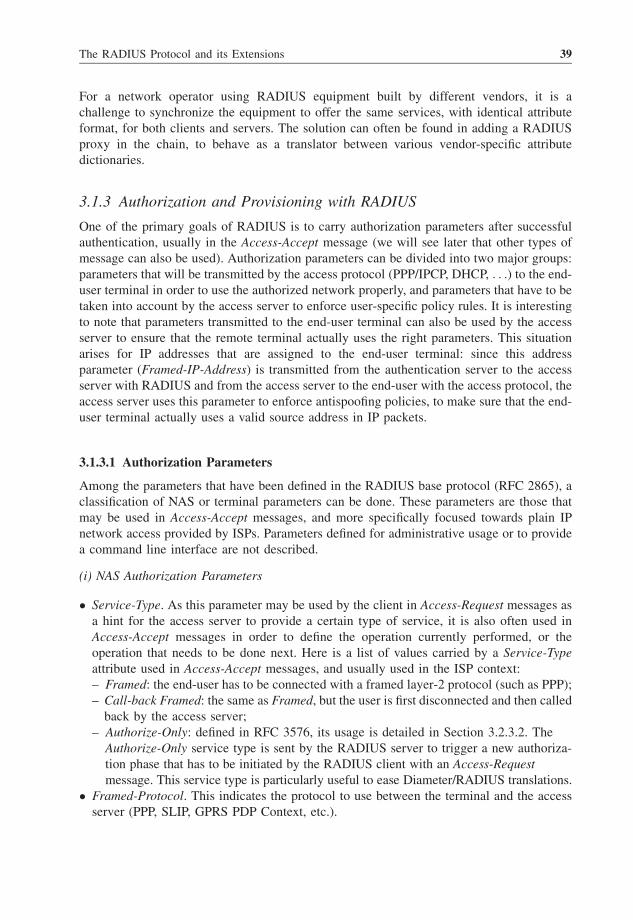
For a network operator using RADIUS equipment built by different vendors, it is a
challenge to synchronize the equipment to offer the same services, with identical attribute
format, for both clients and servers. The solution can often be found in adding a RADIUS
proxy in the chain, to behave as a translator between various vendor-specific attribute
dictionaries.
3.1.3 Authorization and Provisioning with RADIUS
One of the primary goals of RADIUS is to carry authorization parameters after successful
authentication, usually in the Access-Accept message (we will see later that other types of
message can also be used). Authorization parameters can be divided into two major groups:
parameters that will be transmitted by the access protocol (PPP/IPCP, DHCP, . . .) to the end-user terminal in order to use the authorized network properly, and parameters that have to be
taken into account by the access server to enforce user-specific policy rules. It is interesting
to note that parameters transmitted to the end-user terminal can also be used by the access
server to ensure that the remote terminal actually uses the right parameters. This situation
arises for IP addresses that are assigned to the end-user terminal: since this address
parameter (Framed-IP-Address) is transmitted from the authentication server to the access
server with RADIUS and from the access server to the end-user with the access protocol, the
access server uses this parameter to enforce antispoofing policies, to make sure that the end-
user terminal actually uses a valid source address in IP packets.
3.1.3.1 Authorization Parameters
Among the parameters that have been defined in the RADIUS base protocol (RFC 2865), a
classification of NAS or terminal parameters can be done. These parameters are those that
may be used in Access-Accept messages, and more specifically focused towards plain IP
network access provided by ISPs. Parameters defined for administrative usage or to provide
a command line interface are not described.
(i) NAS Authorization Parameters
� Service-Type. As this parameter may be used by the client in Access-Request messages as
a hint for the access server to provide a certain type of service, it is also often used in
Access-Accept messages in order to define the operation currently performed, or the
operation that needs to be done next. Here is a list of values carried by a Service-Type
attribute used in Access-Accept messages, and usually used in the ISP context:
– Framed: the end-user has to be connected with a framed layer-2 protocol (such as PPP);
– Call-back Framed: the same as Framed, but the user is first disconnected and then called
back by the access server;
– Authorize-Only: defined in RFC 3576, its usage is detailed in Section 3.2.3.2. The
Authorize-Only service type is sent by the RADIUS server to trigger a new authoriza-
tion phase that has to be initiated by the RADIUS client with an Access-Request
message. This service type is particularly useful to ease Diameter/RADIUS translations.
� Framed-Protocol. This indicates the protocol to use between the terminal and the access
server (PPP, SLIP, GPRS PDP Context, etc.).
The RADIUS Protocol and its Extensions 39

� Framed-Routing. This is used when the authorized terminal happens to be a router. The
value indicates the routing role of the terminal (route listener, route sender or both).
� Filter-Id. This parameter is very important, probably the most powerful to be used with
RADIUS to communicate authorization policies and rules. The Filter-Id parameter is
indicated by the authentication server, conveying a locally defined reference that can be
interpreted by the NAS. Section 3.1.3.2 talks more extensively about the usage of this
parameter.
� Framed-MTU. When the access protocol does not negotiate this parameter, the Framed-
MTU is used to set the maximum transmission unit to be applied by the NAS for the
remote terminal. Framed-MTU might be different from the MRU value negotiated
between PPP peers, for instance, since PPP-LCP is run before RADIUS exchanges occur.
� Framed-Compression. This is the type of compression to be used between the access
server and the terminal (TCP/IP VJ header compression, IPX header compression, Stac-
LZS compression).
� Callback-Number. The number to be used to call the end-user. This attribute is only
relevant when the terminal is reachable through a PSTN/ISDN network.
� Framed-Route. This parameter is used to provision IP routes for the end-user to be
configured on the NAS. The content of the value field is implementation dependent, but
routes should be noted in a human-readable manner including prefix, subnet (Ascend/xx
notation, where xx denotes the number of high-order bits positioned), the IP address of the
gateway and a set of metrics.
� Vendor-Specific. With Filter-Id, this is a very interesting attribute to convey complex
authorization parameters that can be applied by the NAS (see Section 3.1.3.2).
� Session-Timeout. The value of this attribute specifies the authorized connection duration in
seconds. However, some NAS vendors round off this value to the nearest minute in order
to lower the surveillance burden when thousands of connections are managed by the same
equipment.
� Idle-Timeout. The same as Session-Timeout, but the timer is reinitialized every time traffic
is flowing for the end-user.
� Termination-Action. This attribute is used by the authentication server to inform the NAS
about the next operation to realize. This attribute is used when authentication/authoriza-
tion operations are incomplete. Since Access-Accept messages terminate normal RADIUS
exchange, this attribute is used to continue or to restart the process.
� Port-Limit. This provides the maximum number of ports to be assigned for a specific end-
user. This might be used for multilink PPP, when an end-user makes use of multiple ISDN
channels to increase connection bandwidth.
(ii) Terminal Authorization Parameters
� Framed-IP-Address. This attribute is sent by the authentication server to assign an IP
address to the end-user terminal. The actual IP address assignment of the terminal has to
be performed with the access protocol. For instance, this can be done with IPCP in the PPP
case, or by DHCP. As already mentioned, this parameter can also be used by the access
server to enforce antispoofing filtering policies.
� Framed-IP-Netmask. The same usage as the Framed-IP-Address, this is the network mask
that has to be associated with the IP address.
40 Service Automation and Dynamic Provisioning Techniques in IP/MPLS Environments

� Reply-Message. This attribute is used to display a message to the end-user. It is not a pure
authorization parameter, but it can be used to continue the authentication/authorization
stage when used in Access-Challenge messages, or simply be used as an authorization
notification in Access-Accept messages. This notification has to be transferred to the end-
user thereafter, owing to the access protocol.
� Vendor-Specific. This can also be used to convey information to provision the end-user
terminal with some specific configuration parameters. For example, DNS addresses to be
configured to the end-user terminal are conveyed by RADIUS Vendor-Specific attributes.
3.1.3.2 Conveying Specifically Elaborated Policy Rules
The current set of RADIUS messages makes it possible to provision terminals as well as
access servers with policy rules that can by transmitted in Access-Accept or Change-of-
Authorization messages. The latter, defined in RFC 3576, will be explained more thoroughly
in Section 3.2.3. For RADIUS implementations that do not support RFC 3576, Access-
Accept messages are the only provisioning means that can be used. Since Access-Accept
messages are not acknowledged, it is not always possible to be 100 % sure that authorization
and provisioning parameters have been correctly transmitted and applied. As this is not
really a problem for the initial user connection/authorization request, this may become
problematic if the Access-Accept has been sent within a complementary authorization round,
which occurs when the end-user session is already established. Fortunately, solutions exist to
solve this issue:
� The RADIUS client could be configured to send successive requests if it does not receive
any response from the RADIUS server.
� Accounting messages could be sent as soon as the authorization changed, simultaneously
acknowledging the Access-Accept message and providing an explicit notification detailing
the policy rules applied. This solution is implementation specific.
It is important to note that the IETF RADIUS extensions working group is currently
defining new attributes that are specifically designed to provision filtering rules. This is
discussed in Section 3.2.6.1. Even though these attributes are not yet finalized, and are yet to
be adopted by the IETF community, they are very likely to be used in the future to convey
precise provisioning and authorization rules with RADIUS.
This section will focus on the two standardized attributes briefly mentioned in Section
3.1.3.1, and which can be used to build specifically elaborated policy rules: Vendor-Specific
and Filter-Id attributes. The transport of a complete set of provisioning parameters might not
be possible in a single attribute, since the TLV format (Figure 3.3) imposes a limit of 253
bytes. However, it is possible to convey multiple Vendor-Specific or Filter-Id attributes in
one single RADIUS message. Therefore, proprietary syntax rules have to be implemented
when a large policy rule has to be split into multiple attributes.
(i) Using Vendor-Specific Attributes
The Vendor-Specific attribute has a specific format described in Figure 3.4 and is particularly
suited to configure very different authorization parameters. To define a Vendor-Specific
The RADIUS Protocol and its Extensions 41

attribute, the implementer needs a Vendor-Id number, registered in the SMI network
management private enterprise code (a list of registered companies can be found at the
following URL: http://www.iana.org/assignments/enterprise-numbers). The Vendor-Id attri-
bute is a 32-bit field. Considering that there are less than 25 000 registered companies at this
time, it leaves some room for newcomers. The Vendor-Type field can be freely used within
the Vendor-Id space to dissociate different parameter types such as filtering rules, bandwidth
limitation boundaries, NAT/PAT parameters, etc. The Attribute-Specific value is defined to
make sense with a particular Vendor-Type, and must follow specific syntax and semantic
rules in order to be properly interpreted by the NAS. The RADIUS server also has to
implement this syntax and semantics, especially if it has dynamically to transfer policy rules,
following specific end-user session characteristics. For instance, monitoring and controlling
a specific end-user may require specific IP parameters to be described in the policy rule that
depend on the subscribed service.
(ii) Using the Filter-Id Attribute
The Filter-Id format is very liberal, as the value field is text encoded and is initially used to
designate a particular policy rule already listed in the NAS. There are two different ways to
use this attribute:
� NAS locally defined policy. Both RADIUS server and NAS have the knowledge of the
same set of filtering rules, listed by name or by number (or both) and transported in text
format in a human-readable manner.
� Dynamically interpreted policy. The RADIUS server is able to elaborate dynamic policy
rules in a way that the NAS is able to interpret and to apply the rules in conformance with
the granted service. As this behavior is not explicitly mentioned in RFC 2865, there is no
technical reason to forbid this usage. However, this is not a very practical way to provision
configuration parameters since it requires the implementation of a specific rule parser on
the NAS.
Whatever the Filter-Id usage, the RADIUS protocol operations must not be affected by
this attribute. It is therefore not possible to trigger another round of RADIUS authorization
messages depending on the value of this attribute, for instance.
The Filter-Id attribute is very sensitive to compatibility issues, as the value field usually
has a local meaning and is interpreted depending on the equipment used. This has to be taken
into consideration, especially if services have to be extended to roaming users, and/or if new
incompatible equipment is deployed in the network. For this specific case, the Vendor-
Specific attribute has two advantages: the attribute cannot be misinterpreted (correctly
interpreted or simply rejected), and the attribute can be translated by a proxy if different
equipment brands are involved.
(iii) Example
The following example describes a method to use Filter-Id and Vendor-Specific attributes to
provide the same service. The case presents a registered user Omer who is entitled to connect
to the Internet with a limited speed of 2048 kbit/s for downloads and 512 kbit/s for uploads,
applied to the IP traffic. The provisioning of this bandwidth limitation is done during
connection establishment, by parameters transmitted in the Access-Accept RADIUS message.
42 Service Automation and Dynamic Provisioning Techniques in IP/MPLS Environments

Vendor-Specific AttributesFor the purpose of this example we have defined two Vendor-Specific attributes, especially
created for the virtual ‘Foobar’ company, which was given the enterprise code 30 000
(Vendor-Id). The first Vendor-Specific attribute created by the Foobar company has been
allocated the type number 1 to define the download bandwidth boundary, as the type number
2 defines the upload bandwidth boundary. The choice of the company is to encode the speed
limit in 32 bits, using the integer format. The two newly created attributes are shown in
Figure 3.8.
Filter-Id Attribute with Predefined Local PolicyIn every NAS on which a user has the possibility of being connected, a common set of
services is configured, spanning the whole possible download/upload offers the ISP is able to
provide (Table 3.1).
When the user Omer is connecting to the network, the authentication server will have to
indicate the ‘2048/512’ offer that corresponds to the Filter-Id number 3. In this example, the
Filter-Id value is UTF-8 encoded in a 2-byte length field. The attribute will be as shown in
Figure 3.9.
Type = 26 Lg = 12 Vendor ID = 30000
0 7 15 31
(Vendor ID)
23
Vd-Type = 1 Vd-Lg = 6
2048
Type = 26 Lg = 12 Vendor ID = 30000
0 7 15 31
(Vendor ID)
23
Vd-Type = 2 Vd-Lg = 6
512
Subattribute #1 (download speed limit = 2048):
Subattribute #2 (upload speed limit = 512):
Figure 3.8 Example of two Vendor-Specific attributes defined for bandwidth limitation
Table 3.1 Table of service offers indexed with the Filter-Id attribute
Filter-Id Download limit Upload limit
1 512 128
2 1024 256
3 2048 512
4 8192 512
The RADIUS Protocol and its Extensions 43

Filter-Id with Dynamic InterpretationIn this example, the Filter-Id value field is parsed by the NAS with the following
grammatical rule:
Download Bandwidth Limit ¼ string;Upload Bandwidth Limit ¼ string;Value ¼ ''Service:'' Download Bandwidth Limit ''/''UploadBandwidth Limit;
If the grammatical rules are correctly parsed during analysis of the attribute, the NAS
converts strings into real values to be applied as the bandwidth limit for the user. The
attribute will be as shown in Figure 3.10.
3.2 RADIUS Extensions
3.2.1 EAP Support with RADIUS
The Extended Authentication Protocol (EAP) was primarily designed for PPP (RFC 2284)
but quickly became the standard used for layer-2 links other than PPP. EAP is an access
protocol that makes use of dedicated authentication methods and therefore has to interact
with authentication protocols. RFC 2869 was the first effort to standardize a smooth
interworking between RADIUS and EAP, and RFC 3579 came up afterwards as a complete
solution set, updating the EAP part of RFC 2869.
In order to carry EAP messages from the authenticator to the authentication server, two
new RADIUS attributes have been specifically defined: EAP-Message, which conveys the
Type = 11 Lg = 4 « 03 »
0 7 15 23 31
Figure 3.9 Filter-Id attribute with predefined local policy
Type = 11 Lg = 18
«Service:2048/512»
0 7 15 31
32
64
96
128
Figure 3.10 Filter-Id attribute with dynamic interpretation
44 Service Automation and Dynamic Provisioning Techniques in IP/MPLS Environments

actual EAP information, and Message-Authenticator, which is used to check the message
integrity of request messages, because the original RADIUS Authenticator field is only
relevant for replies. Checking the integrity of requests is a way to prevent spoofing attacks
targeted against the RADIUS server.
The other challenge for a successful interaction was to adapt the RADIUS protocol to the
multipass EAP exchanges. As mentioned earlier, the RADIUS protocol is usually restricted
to a request/response authentication, since EAP methods usually require multiple yet
successive exchanges. To achieve this, Access-Challenge messages are sent by the authenti-
cation server, as long as message exchanges have to be pursued. As in CHAP or PAP
authentication cases, successful or invalid authentication is terminated either by an Access-
Accept or by an Access-Reject message respectively.
The integration of EAP support within RADIUS is a key to use the latter for layer-2 and
layer-3 authorization: EAP is now widely deployed with 802.1X (which is a layer-2
authentication/authorization standard), and RADIUS can be used to integrate additional
layer-3 authorization attributes if the 802.1X authenticator has the corresponding layer-3
capabilities. This case is an example of how RADIUS can easily extend usages.
The complete description of EAP can be found in RFC 3748, but this introduction will
describe in a quick and simple manner what typical EAP exchanges might occur between a
peer and its authenticator (the NAS in our case):
(a) The authenticator (NAS) is the initiator of EAP exchanges, by first sending an EAP
Request message claiming for peer identity.
(b) The peer replies to the authenticator with the required information, by sending an EAP
Response message.
(c) The authenticator sends a new request, requiring a response from the peer.
(d) The (b) þ (c) phases are repeated until all EAP method phases are completed.
(e) If authentication is successful, the authenticator sends an EAP Success message to the
peer; if it fails, it sends an EAP Failure message.
As can be seen above, there are only four messages defined in EAP: Request, Response,
Success, Failure. EAP defines multiple types for Request and Response messages, in order to
specify the nature of the request or response.
An authentication server is not required for EAP to work, as authentication can be
completely handled by the authenticator. However, it is most of the time desirable to make
use of a centralized entity designated to perform the authentication on behalf of the
authenticator. The authenticator may be used in this case as a RADIUS client, and will
have to transmit EAP messages between the peer and the RADIUS server. Note that the
RADIUS server may itself delegate the EAP method processing to an external server, since
authentication computation procedures can be managed independently of RADIUS protocol
exchanges.
3.2.1.1 EAP-Message and Message-Authenticator Description
The EAP-Message (attribute 79) is an attribute used by the authenticator to encapsulate EAP
messages coming from the peer to the authentication server, and is used to convey replies from
the authentication server to be sent to the peer. The EAP-Message attribute can be inserted in
The RADIUS Protocol and its Extensions 45

Access-Request, Access-Challenge, Access-Accept and Access-Reject RADIUS messages. It is
possible to have multiple EAP-Message attributes in a single RADIUS message, as the
maximum size of an attribute may not be sufficient to carry the original EAP message. In this
case, EAP-Message attributes are concatenated to form one EAP message. However, it is not
possible to send one EAP message within multiple successive RADIUS messages, as this
would break the state machine of the RADIUS protocol.
On the other hand, it is not possible for a RADIUS message to carry more than one EAP
message either. The EAP/RADIUS interaction has been built around the idea that every
message of one protocol matches to the other. There is no possibility of message
aggregation, nor reduction of exchanges between the peers.
The Message-Authenticator message (attribute 80) has been defined to ensure integrity
and authentication of RADIUS messages used to convey EAP information within Access-
Request, Access-Challenge, Access-Accept and Access-Reject messages, but can also be used
to reinforce protection of these RADIUS messages, even when not used within the context of
EAP. The value field of theMessage-Authenticator attribute is the calculation of a MD5 hash
of the whole packet, including the Authenticator field and the shared secret used as the key
for integrity check. The essential innovation of this attribute is to protect the server from
spoofed Access-Request messages, whereas the Authenticator field could just be used by the
RADIUS client to ensure the integrity of the RADIUS server’s replies.
3.2.1.2 EAP and RADIUS Exchange Overview
There is a infinite combination of exchanges that might occur between the peer, the
authenticator and the authentication server. Most of the cases that can be encountered are
described in RFC 3579, but we will present here the typical framework of an EAP/RADIUS
message interaction (Figure 3.11):
1. The NAS (authenticator) sends an EAP Request/Identity to the peer.
2. The peer answers with an EAP Response/Identity message.
3. The NAS relays this information to the authentication server within an Access-Request
message.
4. The RADIUS server sends back an EAP Request, hence initiating the actual EAP
authentication method process, within an Access-Challenge message.
5. The NAS relays the EAP Request to the peer and waits for the peer’s answer (which will
be sent in another Access-Request message, by which an Access-Challenge has to be
followed).
6. The peer sends back its answers using an EAP Response message, with a subtype adapted
to the chosen method, and containing the relevant information.
7. The NAS relays the EAP message in an Access-Request message.
Steps 4 to 7 are repeated until the EAP method phases are completed or fail:
� If the authentication server considers that authentication is successful, it encapsulates the
EAP Success message in an Access-Accept message and sends it to the NAS which will
enforce the RADIUS authorization parameters that have to be sent along, and will
simultaneously send the EAP Success message to the peer (step 8).
46 Service Automation and Dynamic Provisioning Techniques in IP/MPLS Environments

� If the authentication fails, the authentication server encapsulates an EAP Failure message
within an Access-Reject message. The NAS will relay the EAP Failure message to the
peer and will take appropriate actions to keep the peer in the appropriate unauthorized
state (step 9).
3.2.2 Interim Accounting
The notion of ‘interim accounting update’ messages appeared in RFC 2869, along with
numerous additional notions, as already seen. In any standard authentication/authorization/
accounting process with RADIUS, the client sends an Accounting-Request message with an
Acct-Status-Type ¼ Start once the session has been authorized by an Access-Accept message
and the NAS has enforced appropriate authorization parameters.
The RADIUS server is intended to send back an Accounting-Response message to
acknowledge receipt and treatment of the message. By the end of the session, the RADIUS
client sends an Accounting-Request message with an Acct-Status-Type ¼ Stop, acknowl-
edged again by the server with an Accounting-Response message. As RADIUS does not
implement a connected mode as Diameter does, the server gets the status of the end-user at
the end of the session, hopefully if no network perturbations have impeached the transmis-
sion of the Stop message.
The benefits of and need for an intermediate status update are then obvious: by sending
periodic accounting messages, the server is able to keep track of active session states more
NAS
(Authenticator)
RADIUS Server
(Authentication Server)
3 - Access-Request+ EAP Message (Response)
8a - Access-Accept
+ EAP Message (Success)
1 - EAP Request/Identity
4 - Access-Challenge
+ EAP Message
(Request for method X)
B-User Rejected
Authenticating peer
Steps 4 to 7 repeateduntil success or failure:
A-Access Granted
2 - EAP Response /Identity
5 - EAP Request for method X
6 - EAP Response for method X7 - Access-Request+ EAP Message (Response)
8b - EAP Success
9a - Access-Reject
+ EAP Message (Failure)
9b - EAP Failure
Provisioning of
authorization parameters
OK
NOK
Figure 3.11 Generic EAP and RADIUS exchanges
The RADIUS Protocol and its Extensions 47

precisely, with the advantage of giving a hint of actual resource consumption. This is helpful
for credit control applications, and also to reduce gain loss whenever end-user consumption
cannot be retrieved because of network failure, for instance. As RFC 2866 prepared the
possibility of Accounting-Request messages with Acct-Status-Type ¼ Interim-Update, its
usage is defined in RFC 2869 with the appearance of a new Acct-Interim-Interval attribute
sent in Access-Accept messages.
This attribute is valued with the interval, expressed in seconds, that separates two interim
updates. Beyond simple indication of the frequency of update messages, it is also a hint
given by the server to the client to activate the interim update process. However, this
mechanism can also be statically configured on the client, and is defined to override the
value provided with the Access-Accept. This last point has been argued lately at the IETF,
since it is impossible remotely to provision a specific behavior for a restricted number of
end-users, as long as a general parameter is set up in the NAS. The last consensus tends to
change this behavior by allowing the Acct-Interim-Interval to override the general para-
meter, if the new value is bigger than the predefined one.
RFC 2869 requires that intervals between two interim updates must not be smaller than 60
seconds, and should be smaller than 600 seconds. These lower boundaries have been defined
to protect the server from bursts of accounting messages, but, in return, they prevent the
accounting server from getting a frequent session status. Changes of authorization might also
trigger the emission of an interim update towards the accounting server. However, this
behavior has not been fully adopted yet, and new standard definitions seem to privilege the
consecutive emission of Stop and Start messages.
Indicating session status changes is possible with consecutive Stop and Start messages
by using the Acct-Multi-Session-Id attribute as a unique identifier for all authorizations
granted during a session lifetime. It is important to note that this method requires
each authorization change to be seen as a session change. In addition to this, a new
Acct-Termination-Cause value would have to be defined in order to specify that there is no
session disruption. In the future, it will be acceptable to foresee that both Interim and
Stop/Start behaviors will coexist: even though the Stop/Start method is a clean way to
achieve accounting for a single session experiencing different authorization phases
through time, it is also predictable that it will have a strong impact on deployed servers
that might improperly process Stop messages, always interpreting it as an indication of
session termination. From this point of view, using interim update messages is less
aggressive.
One future extension of the interim update message can also come from the need for
instantaneous session status updates. ISPs may require the precise status of an end-user
session to be obtained for multiple reasons:
� ‘Ghostbusters’ processes, which are activated when a session is trying to connect as
another one using the same credentials is already online. This situation can occur
whenever an account has been robbed, or when the accounting Stop message of the
first session has been lost for some reason. Instantaneous querying of the session status is a
way to figure out exactly what is going on.
� Real-time consumption checking performed by the end-user, who might pay on a volume
basis, and who is encouraged to check his/her credit regularly in order to avoid
overconsumption penalties.
48 Service Automation and Dynamic Provisioning Techniques in IP/MPLS Environments

� Credit control mechanisms, which can have a dedicated behavior with end-users close to
their credit limit. By requesting more frequent updates from the RADIUS client, usage
measurement is accurately performed without requiring an important update frequency
from the NAS. This is also a way to go below the 60 seconds boundary required by RFC
2869.
3.2.3 Dynamic Authorization
The standardization effort has made RADIUS a particularly attractive protocol to dynami-
cally change authorization parameters for individual sessions. These possibilities are
described in RFC 3576 and have different forms: Disconnect-Request and Change-of-
Authorization (CoA) messages. The former is used to cease authorizations previously
granted to the end-user by invoking the NAS to disconnect the end-user immediately, and
the latter requests the NAS to change authorizations for the indicated session, without
disconnection. The usage of the Disconnect-Request message is inherently limited, and
therefore this section will be more focused on the CoA message.
The first characteristic of these two messages is their place in the protocol architecture.
The traditional client/server RADIUS model makes the NAS the client, whereas Disconnect-
Request and CoA are server-initiated, unsolicited messages. RADIUS clients have to listen
to the specific UDP port 3799 in order to receive these messages. Upon receipt of a
Disconnect-Request message, the client will send back a Disconnect-ACK or Disconnect-
NAK message with an indication of the possible error cause. In the same manner, the CoA-
Request message requires a CoA-ACK or CoA-NAK reply.
CoA messages can be used in two different modes in order to achieve dynamic
authorization changes:
� Push mode: the CoA-Request message directly embeds authorization parameters to be
enforced by the NAS.
� Pull mode: the CoA-Request is a hint sent to the client for the sole purpose of requesting a
new authorization from the RADIUS client. This mode has been defined to ease Diameter
translation.
3.2.3.1 Changing Authorization in Push Mode
This mode is the native mode of the Change-of-Authorization message, as described
in Figure 3.12. It is similar to the Access-Accept message, but used in an unsolicited
manner with some additional restrictions relative to embedded attributes that might not
have the same meaning. The authenticator field is valued with the same rules employed
for accounting messages, keeping in mind that the Authenticator Request does not
come from the client but from the server, and the Authenticator Response comes from the
client.
CoA-Request messages must embed at least one or more attribute precisely and uniquely
to identify the session on which change of authorization parameters will apply. These
attributes can be, among others, the User-Name, Framed-IP-Address or Acct-Session-Id, for
instance.
The RADIUS Protocol and its Extensions 49

All authorization-related attributes described in Section 3.1.3 are usable within CoA-
Request messages, and can be dynamically applied without requiring successive disconnec-
tion/connection to get authorizations for desired services. Upon successful application of
new authorization parameters, the NAS sends a CoA-ACK message to the server. The server
may be forced to rely upon this message to perform the corresponding billing operations, as
the standard does not specify any particular behavior for accounting. The RADIUS client is
not required to send any accounting information to the server. As mentioned in the previous
section, there are, however, two possibilities to alert the accounting server of the change of
authorization: sending an interim update accounting message, or sending successive
accounting Stop and Start messages.
If the NAS is not capable of changing the authorization parameters as requested, a CoA-
NAK message is sent back to the RADIUS server, with an Error-Cause attribute indicating
the cause of failure.
3.2.3.2 Changing Authorization in Pull Mode
This mode is used when the RADIUS server wants to change one session authorization by
means of a regular Access-Request/Access-Accept exchange. To do so, the server sends a
CoA-Request with a Service-Type attribute specifically set to Authorize-Only. Upon receipt
RADIUS Client RADIUS Server
Disconnect-Request
Disconnect-ACK/NAK
User Disconnection Triggered
If User Disconnected(Disconnect-ACK)
Accounting-Request (Stop)
Accounting-Response
COA-Request
COA-ACK
CoA Triggered
SuccessfulChange of Authorization
Change of AuthorizationFailed COA-NAK
Figure 3.12 Disconnect and CoA message exchanges
50 Service Automation and Dynamic Provisioning Techniques in IP/MPLS Environments

of this message, the client will acknowledge this request by sending back a CoA-NAK with
an Error-Cause attribute set to Request Initiated. Eventually, the NAS will send an Access-
Request message with a Service-Type ¼ Authorize-Only to the RADIUS server, which will
send an Access-Accept with the new authorization parameters in return. This is shown in
Figure 3.13.
If the new authorization parameters are not applicable by the NAS, the behavior is not
clearly described. One might expect the Access-Accept to be treated as an Access-Reject
message, which will terminate the ongoing session. We can also expect the Access-Accept to
be treated as an invalid message, and therefore silently discarded without any session
disruption (however, experts do not encourage this). The two opposite behaviors are
documented in standardization notes, and this may create potential problems as each
implementer will have its own interpretation. This is another source of interoperability
issues between implementations. An Accounting-Request message could provide an indica-
tion of whether or not authorization parameters have been applied, but the way to use it is not
precisely defined yet (see Section 3.2.2).
3.2.4 Using RADIUS for Assignment, Prioritization and Filtering with VLANs
Issued in 2006, RFC 4675 defines a set of attributes defined to support VLAN, priority and
filtering attributes. This RADIUS extension is intended to be used in a context where each user
has an IEEE-802 port assigned (either physical or ‘virtual’, as IEEE-802.11 allows). The
bridge to which the port belongs is then the RADIUS client, and may request from the AAA
server an instruction specifically to provision VLAN filtering and prioritization for each user. It
is therefore possible for network administrators to control end-user access to a restricted set of
VLANs, and possible to manage traffic prioritization between VLAN IDs.
RFC 3580 already allows provision of individual VLAN access control for an end-user
attached to an IEEE-802 port. In this case, the tunneling attributes are used, but they provide
a coarse precision of access control tuning. With RFC 4675, the method proposed in RFC
RADIUS Client RADIUS Server
CoA Triggered
Request Processed
COA-Request
(Authorize-Only)
COA-NAK(Request Initiated)
Transmission of New Authorization Parameters
Change of Authorization
Access-Request(Authorize-Only)
Access-Accept
+ authorization parameters
New AuthorizationProcedure Starts
Figure 3.13 Changing authorization in pull mode
The RADIUS Protocol and its Extensions 51

3580 is not deprecated at all, but the new attributes described below are defined to provide
better accuracy in dynamic provisioning of subscribers when attached to a IEEE-802
network.
Four attributes are defined in RFC 4675:
� Egress-VLANID (code 56). The RADIUS server indicates in this attribute an egress VLAN
that is allowed to be accessed by the end-user. It is possible to enumerate a complete set of
authorized VLANs by sending consecutive Egress-VLANID attributes in the same
authorization packet. The attribute format proposes a tag field with which it is possible
to specify whether VLAN frames have to be tagged or not.
� Ingress-Filters (code 57). This attribute activates filtering for VLAN ID(s) specified in the
Egress-VLANID attribute(s), using a field indicating whether filtering is enabled or not.
When filtering is disabled, the end-user associated with the pertaining port has full access
to the desired VLAN.
� VLAN-Name (code 58). Similar to the Egress-VLANID attribute, it indicates authorized
VLAN by its name instead of its number.
� User-Priority-Table (code 59). This attribute is composed of an 8-byte encoded table that
determines a correspondence between the priority of frames received by a port with the
priority to be enforced for the end-user. Therefore, without modifying the priority
information conveyed within 802 frames, it is possible to assign a local and personalized
traffic prioritization. The format of the table is defined in IEEE-802.1d documents.
Among these four attributes, only Ingress-Filters and User-Priority-Table are considered
to be ‘pure authorization attributes’. Therefore, these two attributes are exclusively
transported within Access-Accept and Change-of-Authorization messages. Egress-VLANID
and VLAN-Name are also authorization attributes, but can also be used as a hint sent by the
NAS to the AAA server to provision access with maximum efficiency, when possible.
Using the VLAN filtering and prioritization mechanism in a network can be reported by
using accounting messages. Egress-VLANID, Ingress-Filters and VLAN-Name can be
inserted within Accounting-Request messages to log their usage and application on the NAS.
It is worth noting that these attributes can be used ‘as is’ by Diameter without any other
translation than those required by the protocol format.
3.2.5 Filtering IP Traffic
As seen in Section 3.1.3, it is possible dynamically to provision filter rules into a NAS, even
though it is not really convenient or reliable to be used across a large network, or to be used
across multiple networks. For instance, the Filter-Id attribute requires either filter rules to be
preprovisioned into the NAS or a specific filter rule interpreter to be implemented within
each NAS. With RFC 4005, Diameter does not suffer this problem: the NAS-Filter-Rule
attribute has been defined to convey complex filtering rules in a standardized format owing
to IPFilterRule syntax defined in RFC 3588. With RFC 4849 issued in April 2007, it is now
possible to use the same attribute with RADIUS.
One of the core features proposed is to provide a standardized way to provision specific
per-user filters on the NAS. Previously, this could be done by other means: using the Filter-
Id attribute, or by defining on-purpose Vendor-Specific attributes. Note that the Filter-Id
52 Service Automation and Dynamic Provisioning Techniques in IP/MPLS Environments

attribute may have an ambiguous meaning, since its value field has not been precisely
defined and could therefore embed a sequence of parameters to provide a complex semantic.
The RADIUS NAS-Filter-Rule (code 92) is defined to sweep away good and bad habits by
providing a unified attribute with a comprehensive and elaborate grammar to define filter
rules to be enforced by the NAS. The NAS-Filter-Rule is able to define rules to permit or
deny various traffic flows restricted to layer-3 and layer-4 IP protocols (see Section 4.4.2 for
details). The rules can be complex and may not fit the 253-byte string field limit imposed by
the RADIUS attribute format. In this case, multiple NAS-Filter-Rule attributes can be
inserted in the same message, the concatenation of all string fields giving the complete set of
rules to be interpreted (the string field is ASCII encoded, and the separator between filter
rules is the NULL byte). RFC 2865 mentions that multiple attributes of the same type must
not be reordered, even by proxies in the chain. This rule ensures that rules will be conveyed
without degradation along the AAA chain.
No accounting specific attribute has been defined to report the effective enforcement of a
filter on the NAS. It is the same NAS-Filter-Rule attribute that is used within Accounting-
Request messages. Whenever a filter is applied, either at session startup or during a session,
an accounting message must be sent with this attribute, indicating that it has been taken into
account. If the filter rule is not applicable, the session fails if it is still in its startup phase. If
the session is already up, the session’s authorizations remain unchanged and no accounting
message is sent.
With several methods to enforce filtering policies within an NAS, a rigorous consistency in
attribute usage is required. Firstly, it is not recommended to use the Filter-Id attribute and the
NAS-Filter-Rule attribute at the same time. Even though this is not prohibited, precedence has
not been defined to give priority to one attribute over the other. Therefore, it is likely that
behavior across a large network would not be consistent, especially if different NAS types
were used. The ongoing work at the IETF is preparing a new attribute for filtering traffic, more
powerful and versatile. This will be discussed in Section 3.2.6.1. Even though this new
attribute is not standardized yet, RFC 4849 explicitly mentions that the NAS-Filter-Rule
attribute will have to be ignored if both attributes are present in the same message.
As compatibility with Diameter is required for latest RADIUS attributes, translation
between the RADIUS NAS-Filter-Rule (code 92) and the Diameter NAS-Filter-Rule (code
400) will occur on concatenation and split procedures, to fit the limits of each protocol.
When the Diameter attribute is translated into RADIUS, the Diameter NAS-Filter-Rule string
field is split into 253-byte portions, which makes the same number of RADIUS NAS-Filter-
Rule attributes to be inserted, in the same order, within the equivalent RADIUS message. A
specific translation procedure applies from RADIUS to Diameter when multiple NAS-Filter-
Rule attributes are present. In this case, RADIUS attributes are concatenated into a single
string field which generates one Diameter NAS-Filter-Rule. It might be that translation is
impossible, especially if the 4096-byte RADIUS boundary is reached. In this case,
translation is considered to be unfeasible and an error message is generated.
3.2.6 Future Extensions
The IETF is still engaged in the standardization of new RADIUS extensions. Some proposals
are intended to clarify the usage of RADIUS, or to update some RFC documents to take into
account emerging operators’ needs. We will describe in this section some extensions that
The RADIUS Protocol and its Extensions 53

have a direct impact on end-user service provisioning, especially concerning features such as
traffic filtering, prepaid extensions and bandwidth management. Not all extensions presented
herein are integrated as official standardization working documents yet, and some of them
may not succeed in becoming a standard in the future. However, having a look at these works
will give the reader a better knowledge of the directions to be taken by RADIUS in the
coming years.
3.2.6.1 Extended Filtering Attributes
Throughout the different sections of this chapter we have already identified three different
ways to enforce specific filtering policies onto network access servers: Vendor-Specific
Attributes, Filter-Id and NAS-Filter-Rule. The latter combines the advantages of being
standardized and offering a decent level of sophistication. However, it is still limited to
layers 3 and 4 of the IP protocols, which can be a constraint when provisioning complex
policy rules for individual user access.
Specific work has been conducted to enrich the NAS-Filter-Rule, basically by extending
the RFC 3588 IPFilterRule syntax, using augmented BNF (ABNF) for syntax specifications
(RFC 2234). A new NAS-Traffic-Rule attribute is proposed, which spans from layer-2 to
layer-5 (HTTP) traffic. Moreover, this attribute also embeds actions in order to redirect
identified flows. The same concatenation rules used with NAS-Filter-Rule apply, and it is
likely that Diameter translation would work the same way. At this stage of the work, a
specific attribute is proposed for accounting (Acct-NAS-Traffic-Rule), but it will likely be
dropped following the same solution documented in RFC 4849 and RFC 4675, which
consists in using the same attribute number for authorization and accounting, since no
confusion can exist in the context of their usage.
If the definition of the NAS-Traffic-Rule succeeds in the future, its usage will probably
deprecate all other attributes defined for filtering. It is even possible that NAS-Filter-Rule
may never be used if NAS-Traffic-Rule shows up soon, since NAS and AAA server
implementation supporting the former would not yet be widely deployed. This situation is
even more likely since RFC 4849 explicitly specifies that NAS-Filter-Rule will have to yield
to NAS-Traffic-Rule if both attributes are present in the same message. Considering Filter-Id
and VSA attributes, they will still be used for a long time anyway, because they are already
used in specific situations, combined with a lack of will for additional investments in a chain
that already works and makes money.
3.2.6.2 Bandwidth Parameter Attributes
Besides attributes created to provide additional filtering capabilities such as those described
above, the ability to provision bandwidth limitations to the end-user session is presented in
Ref. [1]. As usually seen with RADIUS, this possibility is already available with most of the
devices available on the market, making use of Vendor-Specific attributes. The purpose of
this proposition is to define three new attributes to define the user’s bandwidth profile:
� The Ingress-Bandwidth attribute defines in its 32-bit value field the bandwidth available to
the user for ingress traffic, i.e. traffic going to the end-user. The bandwidth rate is
represented in the value field in kilobits per second.
54 Service Automation and Dynamic Provisioning Techniques in IP/MPLS Environments

� The Egress-Bandwidth attribute has the same usage as Ingress-Bandwidth for traffic going
in the opposite direction (from the end-user).
� The Bandwidth-Profile-Id attribute provides an opened text field in which the adminis-
trator can designate a bandwidth profile reference to be applied to the corresponding end-
user. This attribute is similar to the Filter-Id attribute but is expected to be used from a
bandwidth management standpoint. It is not intended to be used in roaming environments,
where references are usually locally defined.
Ingress-Bandwidth and Egress-Bandwidth attributes can be used in Access-Request,
Access-Accept, CoA and Accounting-Request messages. In Access-Request messages,
these attributes are used as a hint to the authorization server to recommend a particular
bandwidth, considering the limitations of the NAS or possibly the user’s link. In Access-
Accept and CoA, these attributes are used by the NAS to provision available bandwidth for
the end-user; in Accounting-Request messages, these attributes are used to indicate to the
accounting chain the actual bandwidth applied for the session.
This proposition is not stabilized yet, and it is still unclear whether this proposal will be
standardized some day, even though there are obvious needs coming from network operators
who are continuously dealing with proprietary attributes and subsequent incompatibilities.
3.2.6.3 Prepaid Extensions for RADIUS
This proposition [2] is not an official standardization item yet, but it is in the scope and the
objectives of the RADIUS extension working group to provide a solution that can be usable
for credit control applications, as it has been defined within the Diameter credit control
application (RFC 4006). The purpose is to define additional attributes and usage guidelines
to support new charging models such as duration-based, volume-based and one-time-based
services. The prepaid solution defines a new method for provisioning various credits for the
end-user sessions, the NAS being in charge of managing and measuring the usage of these
credits in real time, reporting this usage to the prepaid server and requiring, if needed,
additional credits.
The ongoing work is far from being completed, and it is not even sure that this proposition
will become a plain standardization document; for this reason, we will not describe this
solution further. The lack of alternative propositions within the IETF makes it almost
impossible to rule on this proposition: the architectural consequences are definitely
important for the future of RADIUS, and it seems reasonable to have multiple solutions
proposed and reviewed by a college of experts.
3.2.7 RADIUS and its Future
Besides protocol mechanisms specified in RFC 2865, multiple RFCs have been written as
companion documents to describe precisely how RADIUS has to be used for particular
purposes. Table 3.2 shows what RFCs define the RADIUS protocol, its extensions and its
usage.
Beyond weaknesses inherited from the very first stages of its birth, RADIUS is still very
flexible. This property makes its use very adaptable for multiple purposes. In addition,
The RADIUS Protocol and its Extensions 55

Table 3.2 RADIUS standardization documents
Title RFC Status Comments
Remote Authentication 2058 Standards Made obsolete by RFC 2138.
Dial-In User Service Track Initial protocol definition
(RADIUS)
RADIUS Accounting 2059 Informational Made obsolete by RFC 2139.
Definition of accounting information
carried with RADIUS
Remote Authentication 2138 Standards Made RFC 2058 obsolete, but itself
Dial-In User Service Track madeobsoletebyRFC2865.Protocol
(RADIUS) definition
RADIUS Accounting 2139 Informational Made RFC 2059 obsolete, but itself
made obsolete by RFC 2866.
Definition of accounting information
carried with RADIUS
The Network Access 2486 Standards Made obsolete by RFC 4282.
Identifier Track Standardized method for user
identification, defines the syntax for
the network access identifier (user
identity presented by the client for
network authentication)
Microsoft Vendor-specific 2548 Informational This RFC gives an overview of
RADIUS Attributes vendor-specific attributes defined by
Microsoft for RADIUS
RADIUS Authentication 2618 Standards Made obsolete by RFC 4668. SNMP
Client MIB Track MIB definitions for RADIUS client
authentication functions
RADIUS Authentication 2619 Standards Made obsolete by RFC 4669. SNMP
Server MIB Track MIB definitions for RADIUS server
authentication functions
RADIUS Accounting 2620 Standards Made obsolete by RFC 4670. SNMP
Client MIB Track MIB definitions for RADIUS client
accounting functions
RADIUS Accounting 2621 Standards Made obsolete by RFC 4671. SNMP
Server MIB Track MIB definitions for RADIUS server
accounting functions
Implementation of L2TP 2809 Informational Discussion about implementation
Compulsory Tunneling issues when performing L2TP
via RADIUS compulsory tunneling using the
RADIUS protocol
Remote Authentication 2865 Standards Makes RFC 2138 obsolete. Base
Dial-In User Service Track protocol definition
(RADIUS)
RADIUS Accounting 2866 Informational Makes RFC 2139 obsolete. Definition
of accounting information carried
with RADIUS
56 Service Automation and Dynamic Provisioning Techniques in IP/MPLS Environments

Table 3.2 ðContinuedÞTitle RFC Status Comments
RADIUS Accounting 2867 Informational Updates RFC 2866 by defining new
Modifications for Tunnel accountingattributes, andbyaddingnew
Protocol Support values to the Acct-Status-Type attribute
RADIUS Attributes for 2868 Informational Definition of new attributes to support
Tunnel Protocol Support compulsory tunneling with RADIUS.
Does not update RFC 2809 which is
more specifically focused for L2TP
RADIUS Extensions 2869 Informational Definition of new attributes for various
purposes such as EAP, ARAP,
Accounting-Interim, Service-Type and
accounting attributes
Network Access Servers 2882 Informational Description of practices and
Requirements: Extended interpretations of implemented
RADIUS Practices RADIUS features
RADIUS and IPv6 3162 Standards Definition of new attributes to support
Track IPv6 characteristics
IANA Considerations for 3575 Standards Updates RFC 2865 about guidance to
RADIUS (Remote Track the IANA regarding registration of
Authentication Dial-In values related to the RADIUS
User Service) protocol
Dynamic Authorization 3576 Informational Definition of new messages to
Extensions to Remote the RADIUS protocol, in order
Authentication Dial-In fora RADIUSserver to orchangeof
UserService (RADIUS) authorizationnotification
RADIUS (Remote 3579 Informational Updates RFC 2869 for the rules to
Authentication Dial-In follow in interacting with EAP
User Service) Support For
Extensible Authentication
Protocol (EAP)
IEEE 802.1X Remote 3580 Informational Suggestions about the RADIUS
Authentication Dial-In protocol usage when used by 802.1X
User Service (RADIUS) authenticators
Usage Guidelines
Remote Authentication 4014 Standards Definition of a DHCP RADIUS
Dial-In User Service Track suboption that could be transmitted
(RADIUS) Attributes from the RADIUS server to the DHCP
Suboption for the Dynamic server through the DHCP relay agent
Host Configuration
Protocol (DHCP) Relay
Agent Information Option
The Network Access 4282 Standards Makes RFC 2486 obsolete.
Identifier Track Standardized method for user
identification, defines the syntax for
the network access identifier (user
identity presented by the client for
network authentication)
(continued)
The RADIUS Protocol and its Extensions 57

RADIUS is evolving within the RADEXT working group at the IETF to support new
features and to extend its usage. The protocol has the ability to carry new accounting
information, and has also evolved significantly to offer sophisticated authorization functions.
With its ability to designate every user context maintained in an NAS, RADIUS is a
privileged medium to enforce individualized policies during the authorization process.
In spite of its lack of reliability, it seems very unlikely that RADIUS will disappear from
the networks within the next 5 years. There are still a lot of functionalities to add (credit
control, extensible attribute definition, etc.), operators are still providing new requirements
and it is a good sign that the standardization process started again in 2004 to define
extensions to the protocol (even though IETF imposed a restricted margin of evolutions).
Even a second-generation evolution such as RFC 3576 for dynamic provisioning is being
reworked again for new improvement.
However, one can easily foresee the end of its evolution, because 3GPP and ETSI have
chosen Diameter for the IMS model, to achieve fixed–mobile convergence. Although
RADIUS was left without any real competitor for years, the growing popularity of Diameter
Table 3.2 ðContinuedÞTitle RFC Status Comments
Chargeable User Identity 4372 Standards Defines new attributes to convey a
Track specific identity for roaming situations
RADIUS Extension for 4590 Standards Extension to support digest
Digest Authentication Track authentication for HTTP-style
protocols such as SIP
RADIUS Authentication 4668 Informational Makes RFC 2618 obsolete. IPv6 support
Client MIB for IPv6
RADIUS Authentication 4669 Informational Makes RFC 2619 obsolete. IPv6 support
Server MIB for IPv6
RADIUS Accounting 4670 Informational Makes RFC 2620 obsolete. IPv6 support
Client MIB for IPv6
RADIUS Accounting 4671 Informational Makes RFC 2621 obsolete. IPv6 support.
Server MIB for IPv6
RADIUS Dynamic 4672 Informational SNMP MIB definitions for RADIUS
Authorization Client MIB client authorization functions, when
RFC 3576 is used
RADIUS Dynamic 4673 Informational SNMP MIB definitions for RADIUS
Authorization Server MIB server authorization functions, when
RFC 3576 is used
RADIUS Attributes for 4675 Standards New attributes for filtering and
Virtual LAN and Priority Track prioritization to VLANs for IEEE-802
Support access
RADIUS Delegated-IPv6- 4818 Standards Defines a new attribute to convey an
Prefix Attribute Track IPv6 prefix to be delegated by the
NAS
RADIUS Filter Rule 4849 Standards Definition of a new RADIUS attribute
Attribute Track inherited from Diameter for IP traffic
filtering.
58 Service Automation and Dynamic Provisioning Techniques in IP/MPLS Environments

will likely push RADIUS aside in the next 3 years for new usages and new network AAA
chain deployments, of course depending on a wide adoption of IMS evolutions by telcos.
References
[1] Lior, A. et al., ‘Network Bandwidth Parameters for Remote Authentication Dial-In User Service
(RADIUS)’, draft-lior-radius-bandwidth-capability-01, July 2005.
[2] Lior, A. et al., ‘Prepaid Extensions to Remote Authentication Dial-In User Service (RADIUS)’,
draft-lior-radius-prepaid-extensions-08.txt, July 2005.
The RADIUS Protocol and its Extensions 59


4
The Diameter Protocol
As the IP protocol became the reference technology to build new networks, the need for a
very reliable AAA protocol was crucial. From the simple requirement of providing an
access on a remote access server in a secured manner, or a connection to the Internet or to
the company’s VPN, needs have strongly shifted to support a more sensitive and demanding
exploitation of networks. New phone access technologies have evolved to support
(and rely on) the IP technology, and therefore this IP technology had to provide an AAA
protocol with new capabilities that RADIUS was unable to offer. Firstly, 3GPP defined the IP
Multimedia Subsystem (IMS) as the architecture design guidelines for the mobile phone
network control plane. 3GPP decided to rely on the Diameter protocol to carry AAA
functions, and to have a role in provisioning appropriate resources in network equipment. In
the beginning, however, 3GPP needs were more oriented to RADIUS evolution of NASREQ
aspects. Next, ETSI/TISPAN decided to adopt the IMS architecture design for fixed
networks built upon IP, meaning that Diameter is now a central piece of technology to be
used in the core of new voice architectures, for both mobile and fixed networks, thus leading
to a real Next-Generation Network (NGN). Diameter is under the spotlight more than ever,
as historic network operators plan to replace the PSTN service with VoIP technologies,
owing to the IMS.
The next sections of this chapter aim to present the requirements that have defined the
Diameter protocol, followed by a presentation of the protocol itself, as well as some use
cases in different network environments, unfortunately not relying upon real-life experience
since operational usage of Diameter is really poor at the time of writing.
4.1 Learning from RADIUS Deficiencies
As seen in Chapter 3, RADIUS is a very powerful protocol, very flexible and easy to
deploy. But RADIUS also has a set of irretrievable drawbacks when the transport of AAA
messages has to be reliable, or when the whole architecture must span to different networks
Service Automation and Dynamic Provisioning Techniques in IP/MPLS Environments C. Jacquenet,
G. Bourdon and M. Boucadair
# 2008 John Wiley & Sons Ltd

in order to provide roaming users an identical connection service wherever they are.
The RADIUS standard is also very delicate to extend since its field size drastically
restricts the numbering space, although this is possible with non-standard proprietary
extensions.
From this standpoint, IETF realized that RADIUS would not be suitable for sophisticated
AAA operations to come, and decided to initiate a process to specify a new protocol, with
backward RADIUS compatibility (a restricted compatibility, of course, considering the
inherent drawbacks mentioned above). Requirements were edited from various standardiza-
tion working groups:
� NASREQ: specific requirements related to the network access server, in order to provide
at least the same level of service as provided by RADIUS;
� ROAMOPS: specific requirements related to roaming operations, as the new AAA
protocol is supposed to service roaming users;
� MOBILEIP: specific requirements related to the mobile IP technology, in order to provide
appropriate messages and features that could be usable for users connected to mobile IP.
The resulting set of requirements (RFC 2989 [1]) were eventually used to evaluate
candidate protocols proposed to fulfill evaluated AAA operations. These requirements
were classified in five distinct categories: general requirements, authentication require-
ments, authorization requirements, accounting requirements and specific mobile IP
requirements.
4.1.1 General Requirements
A set of 14 general protocol capabilities was listed, taking back what RADIUS was already
able to propose, but also including new features such as:
� Scalability. The new AAA protocol must be designed in order to support millions of
simultaneous users, thousands of requests and connected devices pertaining to the AAA
chain. Therefore, all fields must provide enough numbering space to make this possible.
� Fail-over. The protocol must include a mechanism to detect server failures and take
appropriate actions to connect to a backup node.
� Mutual authentication between client and server.
� Transmission level security. The protocol must provide hop-by-hop security at the
transmission layer, i.e. providing authentication, integrity and confidentiality of messages
exchanged between peers.
� Data object confidentiality. This requirement is the first part of the end-to-end security
the AAA protocol has to provide, in order to prevent intermediate nodes of the AAA chain
from analyzing the content of AAA exchanges.
� Data object integrity. This requirement is the second part of the end-to-end security the
AAA protocol has to provide, in order to prevent intermediate nodes of the AAA chain
from modifying data objects conveyed between a client and a server.
� Certificate transport. The protocol must provide the capability to convey certificates
between peers.
62 Service Automation and Dynamic Provisioning Techniques in IP/MPLS Environments

� Reliable AAA transport mechanism. This is a set of requirements representing a major step
forward compared with what RADIUS provides. Basically, each message has to be
explicitly acknowledged without any consideration of the meaning of this message; the
protocol application ensures retransmissions.
� Run over IPv4.
� Run over IPv6.
� Support of proxy and routing brokers. The AAA protocol must embed in its structure all
mechanisms to include third-party actors that may operate proxies or routing brokers not
located on the forwarding path but having the ability to redirect messages to the proper
entity.
� Auditability. The protocol must provide traces of the major actions done on AAA packets
over the traversed nodes.
� Ability to carry service-specific attributes. This requirement is also an important
improvement compared with the RADIUS capabilities. The AAA protocol has to provide
hooks for extensions that may be defined for any application that requires an AAA
function.
Besides classical AAA requirements, the AAA protocol has to propose specific features
for mobile IP support, such as an appropriate encoding of mobile IP registration messages,
an ability to cross proxy-firewalls without altering the quality of AAA exchanges and the
ability to permit the allocation of local home agents.
4.1.2 Authentication Requirements
Beyond general requirements, specific needs have to be taken into account, relative to specific
usage of the AAA protocol for authentication purposes. Firstly, the protocol must provide at
least the same level of functionalities as RADIUS natively embeds, as well as some additional
features that may ease the management of user sessions connected to a NAS:
� NAI support. The protocol must be able to manage network access identifiers that can be
used by users.
� CHAP support. CHAP is commonly used for PPP access and must therefore be supported
to allow a smooth transition, not impacting upon end-user terminal requirements.
� EAP support. EAP is becoming the standard authentication framework for all kinds of
access. The AAA protocol must support the EAP exchange framework.
� PAP support. Even though it is dangerous to use PAP as an authentication protocol,
there are still a large number of users employing it. The AAA protocol must be able to
support it.
� Re-authentication on demand. This requirement describes the ability of an AAA server to
trigger an authentication procedure the AAA client will have to initiate towards a
designated user.
� Authorization only. The protocol must not require user credentials to be transmitted during
the authorization phase.
The Diameter Protocol 63

4.1.3 Authorization Requirements
Besides authentication, there is also a complete set of authorization requirements:
� Static and dynamic IP address assignment. The authorization process of the AAA protocol
must be able to transport a static IPv4/v6 address (the server sends this address explicitly),
or to transport a hint for the AAA client dynamically to assign an IPv4/v6 address to the
end-user.
� RADIUS gateway compatibility. The AAA protocol must be compatible with RADIUS
attributes.
� Reject capability. This requirement makes it possible for an intermediate node such as a
proxy to take non-authorization decisions based on its own set of criteria, either by
blocking access requests or by blocking access authorization messages.
� Re-authorization on demand. This requirement refers to the ability of a server to update
authorization information on the AAA client for a specific end-user. This update can
be triggered either by the server itself or upon a specific request sent by the AAA
client.
� Support for access rules, filters and restrictions. This is an important requirement the
AAA protocol has to fulfill. The AAA protocol must provide means to convey
authorization parameters to enforce specific rules on the access device in order to control
the end-user activity or the quality of service provided to the end-user.
� State reconciliation. This imposes the requirement on the AAA protocol to provide means
to help in state registration of resource allocations for end-user specific authorizations.
� Unsolicited disconnect. This requirement makes the server able dynamically to trigger an
end-user disconnection.
4.1.4 Accounting Requirements
A set of specific accounting requirements has been edited as well:
� Real-time accounting. The AAA protocol must be able to report events simultaneously
with their appearance.
� Accounting record extensibility.
� Batch accounting. The ability to store an ensemble of accounting records to send them
simultaneously to the server;
� Guaranteed delivery. This requirement mandates the server explicitly to acknowledge
accounting messages, to notify the ability to take it into account.
� Accounting timestamps. Every accounting event should have the possibility to be sent with
a time hint.
� Dynamic accounting. This requirement makes accounting behavior compatible with
dynamic authorization. With dynamic accounting, any authorization state that dynami-
cally changes during an end-user session lifetime can be reported to the accounting server.
4.1.5 Diameter is Born
From the whole set of requirements listed above, multiple protocols were potential
candidates, expecting appropriately to answer to AAA challenges. Four protocols were
64 Service Automation and Dynamic Provisioning Techniques in IP/MPLS Environments

mentioned as potential candidates:
� SNMP (RFC 3411 [2]). This protocol was rejected because of the huge engineering work
that would be required to make it a serious AAA protocol, even though it was still
acceptable for accounting.
� COPS (RFC 2748 [3]). This very powerful protocol was seriously considered, taking into
consideration that only few changes would be required to make it a serious AAA protocol.
COPS was particularly appreciated for its data model.
� RADIUSþþ. An extension of the RADIUS protocol to make it compatible with AAA
protocol requirements could have been possible, but it would have required significant
engineering work. Moreover, the final work would likely result in a protocol comparable
with Diameter.
� Diameter (RFC 3588 [4]). However, some changes to the initial protocol specification
were needed to make it compatible with AAA protocol requirements.
Diameter has been considered as the best candidate to support AAA relationships. A
complete evaluation of each of these protocols is made in RFC 3127 [5].
4.2 Diameter: Main Characteristics
The Diameter base protocol (RFC 3588 [4]) has been conceived as a peer-to-peer protocol
that provides support for reliable exchange of information between Diameter nodes, whereas
RADIUS was built as a transactional protocol following a client–server model. The
Diameter base protocol provides the minimum set of functionalities required for any
AAA protocol, including support for accounting, while specific service information is
handled at the application level. Diameter is based upon TCP or SCTP running over IPv4 or
IPv6 (whereas RADIUS runs over UDP), using destination port 3868, thus ensuring a
reliable delivery of the message at the transport layer, even though acceptance of specific
messages requires an explicit applicative acknowledgment, especially for accounting
messages. A Diameter client is not required to support both transport protocols, but
intermediate nodes or servers are mandated to allow a connection with both protocols.
Using a reliable transport protocol also eases failover mechanisms, as a network failure can
be detected without having to wait for an applicative acknowledgment. Explicit applicative
acknowledgment is needed, however, since a network reliable delivery does not mean that
the Diameter process was able to treat the message. This is particularly crucial for
accounting messages that are directly linked to the billing system, and can lead to a loss
of revenue.
The use of TLS or IPSec is also required, in order to ensure security between nodes.
Even though TLS or IPSec is sufficient for hop-by-hop security, it is not a satisfactory
method for protecting the payload all over the AAA signaling path: a proxy-broker,
connected to the Diameter client of network A and to the Diameter server of
provider B, will be able to read sensible payload and correlate identity with resource
usage. The Diameter specification encourages the usage of an end-to-end security
mechanism.
The Diameter Protocol 65

4.2.1 Diameter Network Entities
The Diameter protocol describes three different categories of nodes:
� Diameter client. Designates the Diameter node in charge of providing access to a resource
for which Diameter messages have to be generated. The access device is likely to be a
Diameter client, but it can also be a service platform commanding a policy enforcer that
can control the transport plan.
� Diameter agent. Designates a large category of nodes implied in routing and treating
Diameter messages.
� Diameter server. Designates the terminal node in charge of final AAA operations.
Diameter agents can have various roles, depending on their location in the AAA chain (see
Figure 4.1):
� Relay agent. The relay agent is able to route Diameter messages towards the appropriate
node, depending on the targeted realm to which the message is destined. This routing
operation is realized using the Destination-Realm information embedded in Diameter
messages and the agent action notified inside the message. Therefore, the relay agent
alters the Diameter message by inserting or removing routing information.
� Proxy agent. The proxy agent performs an operation comparable with that of the relay
agent, except that the proxy Diameter is able to modify Diameter messages in order to
enforce a specific (and local) policy. This policy can be related to admission control,
provisioning or resource usage.
DiameterRelay
DiameterRelay
Diameter Server Diameter Server
example.net
example2.net
relay.example.net
server.example.net
relay.example2.net
server.example2.net
DiameterRedirect Agent
redirect.example.net
example3.net
DiameterProxy
Diameter Server
proxy.example3.net
server.example3.net
DiameterClient
client.example.net
Figure 4.1 Diameter chain example
66 Service Automation and Dynamic Provisioning Techniques in IP/MPLS Environments

� Redirect agent. The redirect agent is solicited by other agents to find the path towards the
targeted server. It is envisioned that active Diameter nodes in a network will not be able to
store all routing information for Diameter messages. Interrogating a redirect agent is a
way to dedicate a specific resource to keep route information, and to communicate it to
other Diameter agents.
� Translation agent. The translation agent role is to convert any AAA protocol already
existing (or to come) to Diameter. This is particularly true for RADIUS or TACACSþprotocols, which are required to follow a specific translation to be compatible with
Diameter, even though this translation is eased by attribute compatibility.
4.2.2 Diameter Applications
One important feature of Diameter is to provide the support of different applications. A
Diameter application can be described as a set of messages, attributes and message treatment
rules that are defined to fulfill requirements for a specific usage. So far, five different
applications have been defined to extend Diameter: mobile IP (RFC 4004 [6]), NASREQ
(RFC 4005 [7]), credit control (RFC 4006 [8]), EAP (RFC 4072 [9]) and SIP (RFC 4740
[10]). Diameter also defines a new capability exchange possibility; nodes can advertise what
applications are supported during connection setup, thus ensuring that all nodes of a AAA
chain will support a common set of functionalities. A specific ‘wildcard’ application code
has been defined for relay agents, since relay agents are intended transparently to support all
current and future applications. The Diameter base protocol natively provides the accounting
application. However, it is possible that particular accounting messages do not exist, and
therefore additional accounting applications can be defined. Defining a new Diameter
application should not be abusively employed, and existing applications have to be reused
as often as possible. The Diameter base protocol also defines a set of generic commands that
are related to session management and connection management.
4.2.3 Sessions and Connections
Diameter introduces two important notions that could usually be employed indistinctively in
other circumstances, when talking about end-user connectivity management with RADIUS,
for instance. Diameter connections and sessions have been precisely defined and must be
carefully employed:
� Connection. A Diameter connection is the peering relationship that two Diameter nodes
maintain in order to exchange Diameter commands. A Diameter connection is built over
IPSec and TCP or SCTP as transport protocol. A Diameter connection is not required to
span the whole AAA chain from the client to the server; a connection has to be conceived
as the primary communication relationship between two nodes. It is foreseen that AAA
exchanges cross multiple Diameter connections.
� Session. A session can be understood in the same sense as end-user sessions when
connecting to a network access server. In the RADIUS case, the session is handled by the
RADIUS client for which it has to query a server to ensure authenticity, apply
authorization parameters and provide accounting. With Diameter, the session notion is
The Diameter Protocol 67

quite similar and its reference is unique along the AAA chain. Diameter provides more
reliable session management messages than RADIUS does, especially by separating
session aliveness monitoring from session accounting. Diameter defines specific messages
to manage user sessions that were also added to the RADIUS protocol within RFC 3576,
to change authorization parameters or dynamically disconnect end-users. But Diameter is
still better able to manipulate sessions, as session termination can be notified to the AAA
server without sending accounting information: RADIUS-based AAA chains still rely
upon Accounting-Request/Stop messages to determine whether a session is terminated
or not.
4.2.4 Diameter Routing
The elaborated routing capability is one of the most interesting features provided by
Diameter. It is possible to build a complex AAA chain topology over different networks,
and rely on an efficient forwarding intelligence to enable a Diameter client to reach the
appropriate server, as long as a Diameter path exists between them. As routers provide a
forwarding path over networks to exchange packets between them across multiple auton-
omous systems, Diameter provides the same idea for AAA message forwarding.
To route request messages, Diameter nodesmake use of two specificAVPs:Destination-Host
andDestination-Realm. TheDestination-HostAVP designates the Diameter server that must be
reached to answer the request. The Destination-Host address is encoded as a Fully Qualified
Domain Name (FQDN), such as ‘diameterserver.example.net’. Each Diameter peer maintains a
peer table in order to determine to which peer a Diameter message has to be sent depending on
theDestination-HostAVP content. If theDestination-Host is themachine onwhich themessage
has been received, the message is processed locally. If the Destination-Host is known, the peer
table is consulted and the message is forwarded to the corresponding peer. The peer table
comprises all nodes with which the Diameter node has established a connection. For each node
entry, the peer table maintains useful indications such as peer status, connection expiration time
and TLS activation, as shown in Figure 4.2.
When the Destination-Host AVP is not present in the message, or if the host is not present
in the peer table, the Diameter node has to use the Destination-Realm AVP to route the
message towards a node that will be able to take charge of the Diameter message towards its
final destination. This is possible through the realm-based routing table which defines how
messages have to be processed. If no realm seems able to route the message, the Diameter
message cannot be routed and an error is returned to the message initiator.
The realm-based routing table (Figure 4.3) provides some kind of superset indication of
the direction in which the Diameter message has to be sent. The realm-based routing table
Host Identity Status Static/Dynamic Exp. Time TLSserver.example.net
relay1.example.net
open
open
dynamic
static
1h20m01
12h40m05
disabled
disabled
Figure 4.2 Peer table example
68 Service Automation and Dynamic Provisioning Techniques in IP/MPLS Environments

makes a correspondence between a realm name that is expected to treat the message with a
set of Diameter nodes that are able to route the message in order to reach this Destination-
Realm. The realm information is initially extracted from the network address identifier
(NAI) that was initially used to identify the session requester. The NAI format is defined in
RFC 4282 [11] and usually follows a recognizable format such as ‘[email protected]’.
The realm part of the NAI (‘example.net’) is used by the Diameter client to fill the
Destination-Realm field. The realm-base routing table also provides an indication of the
application supported by the Diameter node to which the message will be sent. If this node is
a relay and not a server, the wildcard application ID will be used, signaling that any kind of
request can be routed through this node. It is important to note that the Diameter peer (server
identifier) indicated in the realm-based routing table has to be present in the peer table to be
valid. When it is time to forward the message to another peer, the peer table has to be
consulted to make sure that forwarding is possible.
The first request for a session is expected to be targeted towards a Destination-Realm
(using the Destination-Realm AVP), and not towards a specific destination (explicit server
address), except if there are specific security constraints. Using the realm to route
messages is a way for Diameter relays and proxies to perform load-balancing between
nodes, and also to determine the best server to use depending on the supported
application. If the Destination-Host is explicitly specified, it is possible to reach a
Diameter server that is unable to run the application requested to process the message.
However, as soon as a first exchange between a client and a server for a session is done,
the Destination-Host can be used in order to reach immediately the node initially
contacted during the first round-trip.
Figure 4.4 gives an example of Diameter message routing for two simple cases where:
� [email protected] wants to connect to his/her home network as s/he is already directly
connected to it;
� [email protected] wants to connect to his/her home network as s/he is connected to a
foreign network.
In case 1, when [email protected] wants to connect to the network (1a), the B-RAS acts
as a Diameter client and determines how to treat the access request. Firstly, the realm name
is extracted from the user identity: example.net is the targeted realm. The Diameter client
checks its realm-based routing table, and a lookup in the realm-based routing table
(Figure 4.3) indicates that the message has to be directly forwarded to server.example.net,
as long as the request applies to the NASREQ case (which is the case in this example).
Afterwards, the Diameter client checks its peer table to get information on server.example.
net (Figure 4.2). Using the corresponding entry, the Diameter client is able to send the
appropriate message (1b) to the Diameter server.
Realm Name App. ID Local Action Exp. TimeStatic/Dynamic
example2.netexample.net static
12h10m515h47m33
Server Identifier
staticRELAYRELAYNASREQRELAY relay1.example.net
server.example.net
Figure 4.3 Realm-based routing table
The Diameter Protocol 69

Case 2 is quite similar to case 1, but the realm name extracted from the user identity (2a)
is different from the local network. The Diameter client checks its realm-based routing table
and determines that requests targeted to example2.net have to be forwarded to relay1.
example.net, whatever the Diameter application. The peer table provides necessary informa-
tion to reach relay1.example.net, and the Diameter message is sent towards it (2b). When
relay1.example.net receives the message, it checks how to treat this message. The Destina-
tion-Realm AVP mentions that example2.net is the targeted domain, and a lookup in its own
realm-based routing table indicates that the message has to be forwarded (2c) towards
relay1.example2.net (following parameters indicated in its own peer table). When relay1.
example2.net receives the Diameter message, the Destination-Realm AVP has not changed
and is used again to find a corresponding entry in its own realm-based routing table. The
Diameter server ‘server.example2.net’ has to be reached to treat the message and is
forwarded accordingly (2d). Once the message arrives on server.example2.net, it is locally
processed. The response message has to follow the same way back to the diameter client (B-
RAS in this example), since every Diameter peer in the path keeps the state of routed
messages in order to ensure reliable delivery between the client and the server. Keeping
message states is particularly efficient for resending messages from intermediate nodes
without requiring specific action from termination nodes.
4.2.5 Peer Discovery
Static configuration of peer and realm tables is a rather fastidious task that network
administrators should get rid of by using DNS. Dynamic peer discovery is optional in
Diameter implementations, but interesting when the Diameter client needs to identify the
B-RAS
Diameter
Relay
Diameter
Relay
Diameter Server Diameter Server
example.net example2.net
client.example.net
relay1.example.net
server.example.net
relay1.example2.net
server.example2.net
2a
2b
2c
2d
1a 1b
Figure 4.4 Complete example of message routing
70 Service Automation and Dynamic Provisioning Techniques in IP/MPLS Environments

peer to which it has to send its requests, and also when an agent needs to discover another
agent to handle a message that needs to be routed to a server. Dynamic discovery of
Diameter peers is not a preliminary action that is performed when a peer starts up: it has to
be performed when required, i.e. when a message has to be routed to another node and no
routing entries in the peer table or realm-based routing table can be used to forward the
message. In this case, a specific request can be sent to a DNS, for instance, to get the FQDN
of the Diameter peer to reach in order to forward the pending message.
4.2.6 Peer Connection Maintenance for Reliable Transmissions
One of the main distinctive approach characteristics of Diameter compared with RADIUS is
the appearance of a connected relationship between two peers that have directly to
communicate between each other. The RADIUS approach was to consider that consecutive
non-acknowledged messages might be considered as a peer failure. This led to an ensemble
of negative side effects: failure detection delay is bad since a peer has to realize several
tentatives to discover and react accordingly; there is an unclear meaning of protocol
messages since a protocol acknowledgement also has an applicative usage; actual useful
messages are used as hints to give a slight flavor of reliability to the protocol, accepting that
operational AAA messages are used for that purpose.
The Diameter approach is totally different: firstly it makes use of a connected IP
transport layer, and provides protocol-specific messages to acknowledge each request and
dedicated messages to test and maintain active connections between peers. This is
achieved owing to Device-Watchdog messages that are sent over the connection at regular
intervals, when no traffic is seen during the corresponding period. Device-Watchdog
messages are useless when AAA traffic is going through the connection, since other
messages avail themselves of transport failure procedures: requests are stored at each node
as long as the corresponding answer is not received. Thus, if the peer to which requests
have been sent is not responding, pending requests can be sent to another node, avoiding
message loss along the AAA path.
4.3 Protocol Details
This section will describe more precisely the message format used by Diameter, as well as
command codes used for the base application.
4.3.1 Diameter Header
The Diameter header format is built as shown in Figure 4.5.
The fields are as follows:
� Version. Indicates the version number of the Diameter protocol used (0x1).
� Message length. Total length of the message including all header fields.
� Command flags. Four flags have been defined:
– the (R)equest bit is used to indicate that the embedded command has to be interpreted
as a request (when this bit is not set, it is an answer);
The Diameter Protocol 71

– the (P)roxiable bit is an indication that the message can be relayed by a proxy or a
Diameter relay, without needing a local processing;
– the (E)rror bit is positioned on answer messages to indicate to the sender that it is
malformed (the corresponding message also contains an error code);
– the Re-(T)ransmission bit is positioned when a message is potentially a duplicate that is
sent when an error occurred during transmission of the original message.
� Command code. Indicates the command code giving the meaning of the present message.
Command code numbering is managed by the IANA.
� Application identifier. The application identifier is used by peers to determine the
Diameter application context into which the message requires to be processed.
� Hop-by-hop identifier. This identifier represents a unique numbering of the present
request, between two directly connected nodes. This identifier is kept between requests
and answers between two nodes: this eases the work of each node in mapping answers to
requests and identifying requests that have not been acknowledged.
� End-to-end identifier. This identifier is used to detect duplicates, using the Origin-Host
AVP to ensure uniqueness of this identifier between a Diameter client and a server. The
number is forged using time information in order to make the number unique when device
reboot occurs.
� AVP. Attribute value pairs used as parameters to complete the action determined with the
command code.
The construction of the Diameter header follows the same philosophy used for RADIUS,
i.e. a command code that determines the nature of the action to be performed, augmented by
pertinent attributes (AVP). This way, Diameter can claim some kind of compatibility with
other AAA protocols such as RADIUS, as it is easy to implement a translation agent that
just has to translate the command code and the Diameter header into RADIUS protocol, and
to move the attributes from one message to the other without (or with minimal) adaptation.
For that reason, the AVP numbers ranging from 1 to 255 are reserved for backward
compatibility with RADIUS, whereas AVP numbers starting from 256 are specific to
Diameter.
Version Message Length
Command Code
0 7 31
AVPs
r r r
Application Identifier
Hop-by-Hop Identifier
End-to-End Identifier
RPE T r
Figure 4.5 Diameter message header
72 Service Automation and Dynamic Provisioning Techniques in IP/MPLS Environments
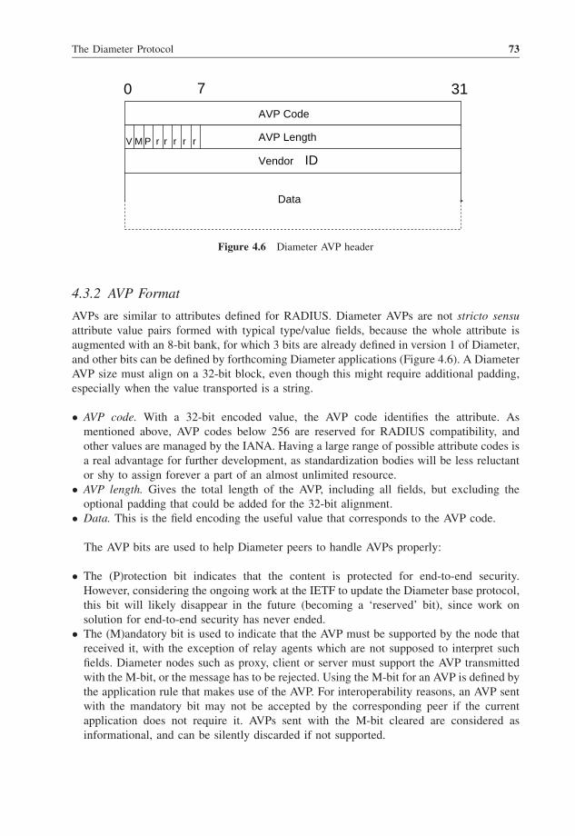
4.3.2 AVP Format
AVPs are similar to attributes defined for RADIUS. Diameter AVPs are not stricto sensu
attribute value pairs formed with typical type/value fields, because the whole attribute is
augmented with an 8-bit bank, for which 3 bits are already defined in version 1 of Diameter,
and other bits can be defined by forthcoming Diameter applications (Figure 4.6). A Diameter
AVP size must align on a 32-bit block, even though this might require additional padding,
especially when the value transported is a string.
� AVP code. With a 32-bit encoded value, the AVP code identifies the attribute. As
mentioned above, AVP codes below 256 are reserved for RADIUS compatibility, and
other values are managed by the IANA. Having a large range of possible attribute codes is
a real advantage for further development, as standardization bodies will be less reluctant
or shy to assign forever a part of an almost unlimited resource.
� AVP length. Gives the total length of the AVP, including all fields, but excluding the
optional padding that could be added for the 32-bit alignment.
� Data. This is the field encoding the useful value that corresponds to the AVP code.
The AVP bits are used to help Diameter peers to handle AVPs properly:
� The (P)rotection bit indicates that the content is protected for end-to-end security.
However, considering the ongoing work at the IETF to update the Diameter base protocol,
this bit will likely disappear in the future (becoming a ‘reserved’ bit), since work on
solution for end-to-end security has never ended.
� The (M)andatory bit is used to indicate that the AVP must be supported by the node that
received it, with the exception of relay agents which are not supposed to interpret such
fields. Diameter nodes such as proxy, client or server must support the AVP transmitted
with the M-bit, or the message has to be rejected. Using the M-bit for an AVP is defined by
the application rule that makes use of the AVP. For interoperability reasons, an AVP sent
with the mandatory bit may not be accepted by the corresponding peer if the current
application does not require it. AVPs sent with the M-bit cleared are considered as
informational, and can be silently discarded if not supported.
AVP Code
AVP Length
0 7 31
Data
r r r
Vendor ID
rrP M V
Figure 4.6 Diameter AVP header
The Diameter Protocol 73

� The (V)endor-specific bit indicates whether the AVP is standardized (bit cleared) or
defined by a vendor for its specific usage (bit set). When the V-bit is set, the Vendor-
Specific field is present in the AVP format to indicate the official SMI company number
used by the vendor, in the same way as with RADIUS.
Diameter allows usage of grouped AVPs. A grouped AVP is an ensemble of multiple
AVPs that are concentrated into one AVP. For instance, this is particularly useful when it is
required to send multiple values corresponding to the same session: all AVPs included in the
group are therefore implicitly linked to each other. A grouped AVP is defined as such in an
application or in the base protocol. As an example, the Proxy-Info AVP is defined as a
grouped AVP of Proxy-Host AVP and Proxy-State AVP in the base protocol. AVPs included
in a grouped AVP are not defined as ‘sub-AVPs’: these are plain AVPs that can be used
alone. On the other hand, it is also possible to imagine several cascaded group layers within
the same AVP in a single message.
4.3.3 Command Codes
As we have seen above, Diameter messages are distinguished by two parameters: the
command code and the (R)equest bit. Formally, there are different messages for requests and
answers, but the Diameter protocol makes them share the same command code; the R-bit is
then used to differentiate a request from an answer.
The Diameter base protocol only defines seven different command codes, corresponding
to seven different kinds of request with their corresponding answer, for a total of 14 different
messages. Only a limited number of command codes have been defined in order to restrict
the base protocol to the very minimum features, i.e. Diameter connection management,
generic session operations and accounting.
(i) Diameter Connection Management
� Capabilities-Exchange-Request/Answer (CER/CEA, command code 257). These two
messages must be used as soon as the transport layer is brought up, in order for two directly
connected peers to exchange their capabilities, such as authentication and accounting
application identifiers, supported vendor attributes or security mechanisms, as well as some
specific parameters such as IP address to be used by each node to identify the source of each
message (which can be different from the IP interface address, especially when a loopback
address is used, for instance). If capabilities exchanged show that there is an incompatibility
between the peers, the connection cannot be effective and the transport layer is torn down.
Because of a scope limited to the connection, Capability-Exchange messages cannot be
forwarded in any manner through a Diameter agent to a remote peer.
� Device-Watchdog-Request/Answer (DWR/DWA, command code 280). These messages
have been defined to improve detection of transport connection failure. The more quickly
peers can react to a failure in the AAA chain, the more efficiently and transparently
failover procedures can be activated. Device-Watchdog messages act as periodic probes
sent over the connection to determine if the remote Diameter instance is still up (which
would not be detected by a traditional ICMP message) when no traffic has been monitored
over the connection for a while. These messages are used to monitor connections and
therefore cannot be routed through a Diameter agent.
74 Service Automation and Dynamic Provisioning Techniques in IP/MPLS Environments

� Disconnect-Peer-Request/Answer (DPR/DPA, command code 282). To improve peer
behavior if one of the nodes needs to shut down a connection, Disconnect-Peer messages
have been defined to give the opportunity to anticipate a foreseen Diameter service
disruption. A Disconnect-Peer-Request message is sent whenever a peer wants to inform
the other peer that the connection needs to be terminated. By doing so, the other peer can
anticipate this by setting up an alternative route to forward Diameter messages. A
Disconnect-Peer-Answer is therefore sent back to the requester to inform that the message
has been taken into account. This message is also useful for preventing disconnected peers
periodically to request a new connection if the service has been terminated for admin-
istrative or technical reasons (maintenance, overload, etc.). These messages are limited to
the scope of the local connection, and cannot be routed through a Diameter agent.
(ii) Generic Session Operations
� Abort-Session-Request/Answer (ASR/ASA, command code 274). Similar to the
Disconnect-Request message used in RADIUS (see Section 3.2.3), the Abort-Session-
Request is used by a Diameter server to trigger a session disconnection on the access
device. This kind of action can be performed, for instance, where authorization previously
granted is no longer valid. Upon receipt of this request, the access device responds with an
Abort-Session-Answer, including the status of the requested operation in the Result-Code
AVP, mentioning whether the action was a success or not. It is interesting to note that,
once the session is terminated, the access device has to issue a Session-Termination-
Request to the Diameter server that can also be followed by an Accounting-Request
message sent to the Diameter accounting server.
� Session-Termination-Request/Answer (STR/STA, command code 275). The Session-
Termination-Request message is used by an access device to notify the Diameter server
that the indicated session is no longer active. The Diameter server acknowledges this
message with a Session-Termination-Answer. This way to proceed is a real improvement
compared with how RADIUS works: each time a session is terminated, the authorization
server is notified of the event, not needing to rely upon a hypothetical accounting message
that could be received and treated by a dedicated non-real-time accounting server.
Moreover, it is possible that some sessions are not required to be accounted (even though
accounting is mandatory most of the time). By separating session management from
accounting messages, Diameter helps in resource management reliability.
� Re-Auth-Request/Answer (RAR/RAA, command code 258). The Re-Auth-Request mes-
sage is used by the service when it is required to ask for a targeted session to be re-
authenticated or re-authorized. However, not all access devices support dynamic user
re-auth, and these messages have to be specifically supported by applications that may
require their usage. By initiating a re-auth of the user, it is possible to refresh the user
authorizations and credits for service usage, from a service management initiative.
(iii) Accounting Messages
� Accounting-Request/Answer (ACR/ACA, command code 271). Accounting messages
have exactly the same meaning when used with RADIUS. The Accounting-Request
message is used by an access device to report accounting information towards a server,
and is acknowledged by an Accounting-Answer message.
The Diameter Protocol 75

To improve reliability in connection management, the Diameter protocol defines the
Origin-State-Id AVP that can be used as a hint sent by access devices to Diameter servers, in
order to determine whether an access device has restarted. The Origin-State-Id is set during
Diameter device startup with an incremental value that can be based upon the current time,
for instance, or upon another parameter as long as the value increases between reboots.
When this AVP is sent within a CER message, this can be a hint for the connected node to
determine whether the access device has lost its sessions, and if corresponding states
maintained have to be cleaned up. Since CERs are only sent one hop away, this can only be
used by proxies or a server directly attached to the access device. A Diameter server has to
wait until the first session request to infer that the access device has rebooted, and that
corresponding states can be deleted.
4.3.4 Accounting
Diameter accounting differs from RADIUS because of an additional record type EVENT
(using the Accounting-Record-Type AVP), besides usual START, STOP and INTERIM
records. An EVENT record is used to notify the accounting server of the completion of a
service that does not have a beginning or an end, but has to be billed as a whole. As a point
of comparison, an EVENTaccounting record can be seen as the concatenation of STARTand
STOP records sent in an atomic message. The EVENT record can also be used to notify a
session establishment failure to the accounting server.
The server also has means to change the access device accounting behavior in the case of
failure, using the Accounting-Realtime-Required AVP. This AVP can be sent by the
authorization server or by the accounting server in an Accounting-Answer message, and
has to be interpreted by the access device to define its behavior whenever a problem occurs
in sending accounting reports. Here is a list of the possible behaviors:
� Deliver and grant. If the accounting record cannot be properly sent immediately to an
accounting server, the access device has to stop the corresponding session.
� Grant and store. As long as the service accounting information can be stored in the access
device, the service can be granted to the session. Once the accounting service starts again,
accounting records are sent. If access device storage resources are exhausted, the service
cannot be granted anymore and corresponding sessions are terminated. This is the default
behavior recommended to be used with Diameter if the Accounting-Realtime-Required
AVP is not present in server messages.
� Grant and lose. In this case, accounting information is used by the server as a hint, and it
is not required to offer the service. The service is not affected by accounting server
connectivity problems.
4.4 Diameter Network Access Application (NASREQ)
The NASREQ application was one of the first reasons for the existence of Diameter, in
order to improve RADIUS for remote access management. As seen in Section 4.3.3,
command codes defined within the Diameter base protocol specification are not
sufficient for an access device to require a server to perform authentication and grant
76 Service Automation and Dynamic Provisioning Techniques in IP/MPLS Environments

related authorizations for a new session. The Diameter network access application
(NASREQ) (RFC 4005 [7]) defines only one new command code for this purpose:
Authentication-Authorization-Request/Answer (AAR/AAA, command code 265). This
new message is an equivalent of Access-Request/Access-Accept/Access-Reject
messages used in RADIUS, but also replaces Access-Challenge messages which are
used when multi-round authentication/authorization is required, with EAP for
instance.
Apart from the new AAR/AAA message, the NASREQ application relies upon the
following Diameter messages defined in the base protocol:
� Re-Auth-Request/Re-Auth-Answer;
� Session-Termination-Request/Session-Termination-Answer;
� Abort-Session-Request/Abort-Session-Answer;
� Accounting-Request/Accounting-Answer.
It is possible that some authentication protocols require a multi-round authentication: EAP
is a well-known example of this particularity, the number of round-trips between the end-
user (therefore the access device) and the authentication server being highly dependent on
the EAP method used (see Section 3.2.1). Doing multi-round authentication with RADIUS
requires a workaround making use of the Access-Challenge message that could be sent right
after an Access-Accept has been received from the server. Using the Access-Challenge
message was motivated by the interdiction of sending an Access-Request after an Access-
Accept message.
Diameter does not make use of Access-Challenge messages anymore, and instead makes
it possible to send an AA-Request message after an AA-Answer coming from the server.
As defined in the Diameter base protocol, the Result-Code AVP included in the latter
message thus indicates this property with a value code set to DIAMETER_MULTI_R-
OUND_AUTH.
4.4.1 AVP Usage for NASREQ
The NASREQ application is essentially focused on RADIUS compatibility and makes use of
the majority of RADIUS attributes (with an attribute value below 256), forbidding the use
of some of them, replacing others. Additional AVPs have been defined for the specific use of
Diameter:
� CHAP AVPs. CHAP-Auth (code 402), CHAP-Algorithm (code 403), CHAP-Ident (Code
404), CHAP-Response (code 405) are used when the end-user wants to authenticate using
the challenge authentication protocol (CHAP). The CHAP-Auth AVP is a grouped AVP
embedding the three aforementioned, and must replace the use of the RADIUS CHAP-
Password attribute.
� NAS authorization AVPs. NAS-Filter-Rule (code 400) and QoS-Filter-Rule (code 407) are
two very important AVPs that enrich authorization possibilities. These attributes are
described further in Section 4.4.2. The NAS-Filter-Rule attribute has been recently
standardized for RADIUS, and a similar effort is engaged for QoS management to extend
what already exists for Diameter and to make it available for RADIUS. These efforts are
carried on within the DIME working group (IETF).
The Diameter Protocol 77

� Tunneling AVP. The Tunneling AVP (code 401) is a grouped AVP that embeds all other
AVPs defined for tunnelling with RADIUS (defined in RFC 2868, see Chapter 3). This
grouped AVP can be seen as a replacement of the ‘tag’ field used in tunnel attributes: the
basic purpose of this field is to give the tag value to tunnel attributes that refer to the same
tunnel configuration. Therefore, a single message could convey multiple tunnel config-
uration attributes. Using multiple Tunneling AVP is a more consistent way to achieve the
same thing with Diameter.
� Accounting AVPs. Besides AVPs already defined in the Diameter base protocol and for
RADIUS, NASREQ provides a new Accounting-Auth-Method AVP (code 406) to
indicate in accounting messages the authentication method used by the end-user
(PAP, CHAP, EAP, etc.). Four new attributes are also defined to replace those used
with RADIUS to report data traffic usage: Accounting-Input-Octets (code 363),
Accounting-Output-Octets (code 364), Accounting-Input-Packets (code 365) and
Accounting-Output-Packets (code 366). These replacements are required because of
the field format change which is now unsigned 64 bits, instead of the 32-bit value
previously used. It is important to note that the Accounting-Record-Type (code
480) defined in the base protocol to identify the record type of the accounting
message (Start, Stop, Interim, Event) replaces the Acct-Status-Type used with
RADIUS.
4.4.2 Enhanced Authorization Parameters
The two new AVPs, NAS-Filter-Rule and QoS-Filter-Rule, have been defined to enforce
enhanced policies from the authorization server to the access device for a particular session.
It is recommended that usage of the Filter-Id RADIUS attribute be avoided in the NASREQ
context, because of its loose definition which makes it almost impossible to have a
deterministic behavior: each vendor is free to implement its own syntax. Other RADIUS
authorization parameters such as Session-Timeout are still present and usable with Diameter,
and will therefore not be described in this section.
Both NAS-Filter-Rule and QoS-Filter-Rule AVPs are defined in NASREQ, but the
attribute format is defined in the base protocol. The NAS-Filter-Rule AVP is interpreted
by the access device in order to apply traffic filters relative to the protocols transmitted on a
session, whereas the QoS-Filter-Rule is used to treat the user traffic by marking or metering
it, as defined in the DiffServ Architecture (RFC 2475 [12]). The format of these AVPs is
described below.
The value field of these AVPs must comply with the following syntax, but is interpreted
differently:
action dir proto from src to dst [options]
(i) NAS-Filter-Rule AVP
action: permit or deny.
dir: from the terminal (in) or to the terminal (out).
proto: IP protocol specified by its number, the ‘ip’ keyword can be used as a wildcard.
src and dst: specifies the address and netmask, as well as the port numbers, using the syntax
address[/bits_ masked]<address[/bits_masked]> [ports].
78 Service Automation and Dynamic Provisioning Techniques in IP/MPLS Environments

options:
� frag: the criteria is matched if the IP packet is not the first fragment of a datagram.
� ipoption <spec>: spec is used to identify the part of the IP packet header that may match
the filter. Spec can be ‘ssrr’ for strict source routing, ‘lsrr’ for loose source routing, ‘rr’ for
record route and ‘ts’ for timestamp. Multiple header options can be mentioned, separated
with commas.
� tcpoption <spec>: similar to ipoption, tcpoption is used to apply filters on specific TCP
fields of the IP datagram. Spec values can be ‘mss’ for maximum segment size, ‘window’
for TCP window advertisement, ‘sack’ for selective ACK, ‘ts’ for timestamp and ‘cc’ for
T/TCP connection count.
� established: filter matches TCP packets that have the RST or ACK bits positioned.
� setup: filter matches TCP packets that have the SYN bit positioned, but not the ACK bit.
� tcpflags <spec>: filter matches TCP packets that have positioned bits specified in spec:
fin, syn, rst, psh, ack, urg. The filter can also specify bits that must not be positioned by
prepending a ‘!’ before mentioning the bit reference.
� icmptypes <types>: filter matches ICMP packets that have the type(s) specified in types.
Multiple type values can be specified in a single filter, separated by commas. The type
values are: 0 (echo reply), 3 (destination unreachable), 4 (source quench), 5 (redirect), 8
(echo request), 9 (router advertisement), 10 (router solicitation), 11 (TTL exceeded), 12
(bad IP header), 13 (timestamp request), 14 (timestamp required), 15 (information
request), 16 (information reply), 17 (address mask request), 18 (address mask reply).
(ii) QoS-Filter-Rule AVP
action: tag or meter.
dir, proto, src and dst similar to the NAS-Filter-Rule.
options:
� The ‘DSCP <value>’ option has to be used with the tag action to change the DSCP field
of the header of IP packets that match the rule.
� The ‘metering <rate> <value_under> <value_over>’ option has to be used with the
meter action to change the DSCP field of the IP packet header to ‘value_under’ if the
traffic throughput is below the defined ‘rate’, or to ‘value_over’ if it goes beyond. It is
interesting to note that ‘value_over’ can explicitly mention a ‘drop’ action to destroy IP
packets without marking it.
Access devices have to behave the same way for filters provisioned through NAS-Filter-
Rule or QoS-Filter-Rule. The first filter entry that matches the inspected packet stops the
evaluation over the filter list. Comparison of packets with filters is done following the place
of each filter in the list. The place of a filter is determined by its order of installation within
the access device. If the last evaluated rule is a permit and no rules are matched, the packet is
dropped. On the other hand, if the last evaluated rule is a deny and no rules match, the packet
is forwarded. This behaviour is very similar to Access-List evaluation rules usually
configured in IP routers. A single authorization message can include multiple filter rules,
and this is foreseen to be the usual case. The place of each filter in the packet will determine
the place of the corresponding filter in the access device evaluation list.
The Diameter Protocol 79

4.4.3 Enhanced Authorization Examples
1. The example provided in Section 3.1.3.2 to offer different bandwidth profiles for end-
users can be provisioned using two QoS-Filter-Rule AVPs sent within an AA-Answer, for
instance. The purpose of this example is to set a bandwidth limit of 512 kbits/s for
download and 128 kbits/s for upload traffic. The way to achieve this is to use the meter
action of the QoS-Filter-Rule, and to drop packets that go beyond the specified limit.
Other packets can be marked with the default 000000 DSCP value, corresponding to the
best effort.
The rule for download traffic could be
Meter out ip from 0.0.0.0 to 0.0.0.0 metering 512 000000 drop
The rule for upload traffic could be
Meter in ip from 0.0.0.0 to 0.0.0.0 metering 128 000000 drop
However, using rules of this kind has some limits: it becomes impossible to enforce an
additional policy to the traffic because the traffic successfully evaluated over this rule will
stop the evaluation if there are remaining filters after. On the other hand, the rate limit will
not work if other rules are previously matched before evaluating this one. Finally, these
rules also override the DSCP field that could have been positioned by other equipment in
the forwarding chain. This might be a drawback if the NAS session is used to convey
traffic between two company premises that require prioritization. For this reason,
bandwidth limitation is still tricky to achieve even with Diameter, and using the Filter-
Id AVP may remain the most reliable way to achieve it, even though its usage is not
recommended. It is also possible to define Vendor-Specific attributes for that purpose, but
it is no more roaming friendly than the Filter-Id AVP.
2. The example below shows how to authorize only HTTP exchanges towards a single
service platform, to pay additional services that could further change the filtering options
and all kind of traffic for the end-user. The service platform is represented by the address
10.0.10.10, and the DNS address that must be reached by the end-user to get HTTP
redirection is 10.0.11.11. Once the end-user is connected and opens its web browser, the
first DNS request leads to the service platform whatever the URL. The user is constrained
to exchange traffic to these two addresses as long as other authorization parameters are
provisioned onto the access device. The HTTP traffic to the service platform is identified
by use of TCP (protocol number ¼ 6) and port 80.
The rules to open outgoing traffic to the DNS server and the service platform are:
Permit in 6 from 0.0.0.0 to 10.0.10.10 port 80
Permit in ip from 0.0.0.0 to 10.0.11.11
Permit out 6 from 10.0.10.10 to 0.0.0.0
Permit out ip from 10.0.11.11 to 0.0.0.0
Each packet that does not match any of these four rules will be dropped. To allow the
end-user to reach any address among the Internet space, and to prevent him/her from
sending packets to administrative IP addresses of network equipment using the
192.168.0.0/16 subnet, two solutions are possible:
80 Service Automation and Dynamic Provisioning Techniques in IP/MPLS Environments

� A RAR message with a Re-Auth-Request-Type AVP set to ‘AUTHORIZE_ONLY’ is sent
by the authorization server (upon request of the service platform, most likely), including
new filters in the payload. The new rules will have to override already existing filters. This
way to proceed is, however, not specified in the Diameter base protocol or NASREQ.
� A RAR message is sent to the access device to trigger the creation of a new subsession
that will require a new AAR/AAA message for which new filters will apply.
It is important to note that temporary access authorization to network resources is far
better managed by using the Diameter credit control application (RFC 4006 [8]) that has
been defined for this purpose. NAS-Filter-Rule and QoS-Filter-Rule are better suited to be
applied when permanent traffic filtering is required. Bandwidth management, as in the
example shown above, is usually performed using application extensions. ETSI/TISPAN and
3GPP use new AVPs that have been defined for that purpose. Even though it is encouraged to
use existing messages and AVPs to realize a specific service, it is not always the most
suitable way to achieve it. Diameter extensibility is a real strength that operators must use
wisely: creating a specific application, or defining Vendor-Specific AVPs can be the best and
simplest solution, and should be even easier to do with Diameter than with RADIUS.
4.5 Diameter Credit Control Application
The credit control application (RFC 4006 [8]) is a very interesting application for Diameter.
However, its complexity and the study of all possibilities it offers would warrant a book
dedicated solely to this topic. Implementing a credit control feature in access devices and
AAA servers is the ultimate way to give a business face to provisioning in IP/MPLS
networks: the purpose of this application is not another way to provide fancy user traffic
management. Credit control ‘philosophy’ is based upon real-time service usage monitoring,
performed by the access device, for every end-user that has opened a session related to a
service that can be consumed with a control provided by the service provider through its
AAA server. On the service provider side, the AAA server has to provide, for each session
requiring it, a granted quota of credits that will be consumed at the access device. The access
device is in charge of monitoring this resource consumption, to request additional credits for
the end-user for service continuation, and to report unused credits that will be credited to the
end-user account. This can be seen as an alternative accounting method that has been
designed for real time, whereas usual accounting procedures as defined in the base protocol
are more likely to be used for batch processing.
Credit control is defined towork in two different modes: credit allocation and direct debiting.
When used in credit allocation mode, each credit control request will cause a reservation on
end-user credit resources. The actual debiting of the reserved credit is realized when the service
has been provided. When used in the direct debiting mode, the required credit is directly
calculated and debited from the user’s account. This mode is particularly suitable for one-time
services, which are paid as a whole and are immediately due without refunding policy.
The credit control application is agnostic to the type of service for which the end-user is
ready to pay, but both access device and credit server have to agree on which service the
network has to provide. The server must have the service knowledge to be able to calculate
the appropriate credit required by the access device to provide a decent service, and to make
The Diameter Protocol 81

its calculations based upon a rating that has been defined previously by the service provider.
The access device cannot perform this task, especially when the end-user is not connected to
its home network: the credit calculation must be realized by a centralized unit with a
consistent behavior over traversed networks. However, access device and server have to
share a similar vision of the service to provide, otherwise granted resources can exceed the
units corresponding to the paid service, or, even worse, the service may not be satisfactory
because of credit burning faster than expected.
Nor is the AAA server aware of the complexity of service to be provided: the access
device is in charge of providing the respective service, monitoring its usage and requesting
credit for end-user access. The credit control application may rely upon other Diameter
exchanges that might previously occur to make the service possible. For instance, credit
control can make use of AA-R and AA-A messages defined in NASREQ to credit specific
resources for the established session. But credit control can also be invoked after exchange
of SIP messages. Credit control Diameter exchanges are materialized by two new messages
(regrouped in one command code): Credit-Control-Request (CCR) and Credit-Control-
Answer (CCA) with command code 272.
Multiple services can be provided simultaneously for a single end-user by means of
subsessions. Each subsession will have its own credit control context (as well as its own
subsession context): sharing the available credit is the challenge of the credit server, which
has to split the resource with the appropriate granularity such that a service does not reserve
too many resources to the detriment of other services. On the other hand, splitting the credits
into too many small units might create an important credit management overhead because of
frequent credit updates.
The resources provided by the credit server to the access device is not only money, but more
generally one can talk about granted ‘units’. Units can be of different nature: they can be
money, but also remaining time, amount of data to be exchanged or any units that could be
defined for a particular purpose. Credit control is not only session based – it can also be event
driven, for instance upon receipt of an SIP message to signal emission of SMS: this service can
be achieved in a one-shot direct operation, not requiring a session context to be maintained.
It is important to note that credit control messages and AVPs as defined in RFC 4006 [8]
have been defined upon request of 3GPP for IMS. 3GPP as well as ETSI/TISPAN have
themselves added multiple AVPs to be used in the context of credit control to provide
conversational services within a fixed–mobile convergence framework.
4.6 Diameter in NGN/IMS Architecture for QoS Control
This section does not pretend to provide an exhaustive view of when and how the Diameter
protocol is used within NGN architectures – and accurate description of what next-
generation networks (NGNs) actually are would alone require more than one book. We
will start here with a simplified and overall view of what a NGN is, and we will focus on the
QoS control architecture as defined within ETSI/TISPAN.
4.6.1 What is an NGN?
Considering the extreme complexity of NGN architectures, one might question the purpose
of all this. The goal that NGN intends to achieve is to make networks, wherever in the world,
82 Service Automation and Dynamic Provisioning Techniques in IP/MPLS Environments

interoperable, for both data and voice (and actually all services), whatever the access method
(mobile or fixed lines), relying upon IP networks. Therefore, deploying NGN architectures is
the way to achieve fixed/mobile convergence.
Nowadays, NGN is often associated with IMS: this is true, but IMS is only a part of
the NGN architecture. IMS was first defined within the 3GPP (Third-Generation
Partnership Project), the standardization body in charge of defining the third generation
of mobile architectures. The purpose of the IMS is to provide a multiservice, multiaccess
architecture that is secure and reliable. IMS has been designed to be an enabler for
providers to propose real-time and non-real-time services, where the user is mobile and
wants to use multiple services simultaneously. The IMS blocks were firstly defined in
Release 5 of the 3GPP architecture. The next release (R6) issued in 2004 enhanced the
previous release of IMS by including dynamic policy control enhancements for end-to-
end QoS. One of the key characteristics of the IMS architecture is to be adaptable
whatever the transport network, as long as it works over IP. For this reason, IMS has
been adopted by ETSI to standardize NGN architecture for fixed lines (whereas 3GPP
focuses on mobile access), to define the TISPAN (Telecommunications and Internet
converged Services and Protocols for Advanced Networking) architecture. 3GPP IMS
blocks and interfaces are reused by ETSI/TISPAN, with adaptations to the context and
thus some changes in the naming of interfaces.
NGN functional architecture as defined within ETSI/TISPAN (see ETSI ES 282001 [13])
defines two fundamental distinct layers: the transport layer and the service layer. The service
layer consists of several components, IMS being one of them, designed to be in charge of
multimedia conversational services. Other components have already been defined, such as
the PSTN/ISDN emulation subsystem. The service layer model is open, and new compo-
nents can be defined as required (such as the content broadcasting subsystem, for instance).
Splitting NGN architecture into different layers helps in separating functions and mutualiz-
ing infrastructure to optimize investments. The goal is also to provide end-users with a
seamless view of subscribed services whatever the access mode. An overview of NGN
architecture elements is shown in Figure 4.7.
The service layer interacts with other layers and entities:
� user equipment;
� transport layer;
� other networks.
The transport layer itself comprises the three following components:
� Transfer functions. These take on all actions that can be applied to traffic coming from or
to users’ equipment and other networks. Several functions have been identified and
described within ETSI/TISPAN, with specific roles. For instance, the layer-2 termination
function (L2TF) is in charge of the layer-2 termination procedures at the edge of the
access network. Another important function is the border gateway function (BGF) which
is in charge, among other functionalities, of NAT/NAPT actions, packet marking, resource
allocation and bandwidth reservation.
� Network attachment subsystem (NASS). This component takes care of functionalities to
attach the terminal to the network. Among its functionalities we have: dynamic
The Diameter Protocol 83

provisioning of IP addresses (e.g. DHCP), authentication to access to the IP layer (distinct
from the service attachment/authentication), location management.
� Resource and admission control subsystem (RACS). This component provides function-
alities for admission control and gate control (such as NAT) by interworking with other
components of the network to check network resource availability and capabilities. This
entity will also check if the user’s profile is compatible with the requested resources. The
RACS is in charge of collecting resource requests from the service layer, and of pushing
the corresponding policies to the transfer equipment.
All these components are themselves composed of smaller parts, each assuming a subset
of standardized functionalities. The goal of standardization bodies, apart from describing
these blocks and their usage, is to define interfaces to make them interact appropriately
across entities, components and layers.
Transfer Functions
Applications
Network Attachment
Subsystem
Resource and Admission
Control Subsystem
User
Equipment
Other
Networks
TransportLayer
ServiceLayer
Other
SubsystemsPSTNISDN
Emulation
SubsystemCoreIMS
Figure 4.7 Overview of NGN Architecture in ETSI/TISPAN
Transport Layer
UserEquipment
P-CSCF I/S-CSCF
Application
Server
“Core IMS”
SIP SIP
SIP
Diameter
Figure 4.8 A simplified view of core IMS interactions with the user’s equipment and the transport
layer
84 Service Automation and Dynamic Provisioning Techniques in IP/MPLS Environments

Talking about protocols, the session initiation protocol (SIP) (RFC 3261 [14]) is the
privileged protocol to be used within the ‘core IMS’ and by user equipment (see Figure 4.8).
SIP is preferred for the service layer, to control interactions between the user equipment
(UE) and the application server (AS). SIP messages cross several entities within the service
layer, such as the call session control function (CSCF). These entities are themselves able to
interact with other layers in the NGN architecture, but then SIP is not the protocol chosen to
interface entities, and Diameter is often privileged.
We will now focus on the QoS control architecture by describing interactions between
entities, implying Diameter.
4.6.2 QoS Control in ETSI/TISPAN Architecture
QoS control follows a very straightforward logic in NGN architecture (Figure 4.9).
The reader will note the appearance of a new component, the application function (AF).
This is the generic terminology used to designate the entity located in the service layer that is
in charge of interacting with the transport layer. In an IMS architecture, the AF would be the
P-CSCF (Proxy-Call Session Control Function), the role of which (among others) is to
extract from SIP messages the network capabilities required to provide the service, and to
ensure that these capabilities are present.
Here is an overall description of the procedure that applies to enforce QoS policies in the
network, in order to provide the service requested according to the network policy rules and
capabilities:
1. Network attachment. During this phase, the user equipment attaches itself to the network.
This includes authentication, authorization based on the user’s profile (including
provisioning of the IP address) and start of accounting related to network attachment.
It is important to understand that this phase is not related to any service whatsoever.
Attaching to the network and having an IP address to communicate is not considered as a
service per se, as it does not require any interaction with the service layer. During the
network attachment phase, the NASS can communicate to the RACS resource informa-
tion that is specific to the entity that has just connected.
NASS RACS
Transfer Functions
AFService Layer
Transport Layer
UE
1
2
3
1’
5
4
Transport Control
Figure 4.9 QoS control mechanisms in NGN architecture
The Diameter Protocol 85

2. Service request. This phase occurs whenever the user equipment sends requests to get a
service from the network. The most common service might be thought to be placing a
phone call, using VoIP with IMS. This step consists in exchanges of SIP messages with
the service layer. In the case of IMS, the AF is the P-CSCF which is in charge of receiving
SIP messages from the UE, forwarding it to other entities of the service layer and,
depending on the result of the service request, interworking with the transport layer to
reserve resources.
3. RACS location. This phase is optional and consists in the AF getting information to
connect with the right equipment to connect to the RACS. For this, the AF just requires an
IP address or a FQDN, and this information can be provided to the AF by the NASS.
4. Resource request. Once the service application has performed the first verifications to
check if the end-user is entitled to use the requested service, the application function
requests from the RACS the appropriate network resources in order to get the corre-
sponding quality of service. The RACS will then check if the requested resource is
available. At this stage it is interesting to note that the RACS can ask the NASS for
specific information on the connected entity requesting the resource if this information is
not available during phase 1.
5. Policy provisioning. Once the RACS has verified that the network resource is available to
provide the service, it communicates with entities of the transfer plan within the transport
layer to push the policies. Once these steps have been successfully completed, the UE is
notified that the requested service is available, and it can start to use it.
The big picture provided above requires a little more description, in order to see the
protocols and interfaces that are involved in these phases. We will now look more thoroughly
into the RACS and the transfer functions.
Here is a brief description of the entities that appear in Figure 4.10:
� A- RACF (Access-Resource and Admission Control Function). This entity has two main
roles in the RACS:
– Firstly, it provides the admission control function by checking if the QoS resources are
available when a request is received by the SPDF for an access line. For instance, one
might consider that having simultaneous video calls depends on the characteristics of
the end-user’s access line (or subscription). In this case, the A-RACF will perform
admission control by granting or rejecting the service, because of resource scarcity. In
this role, the A-RACF is capable of installing some policies onto the RCEF and on the
access node.
– Secondly, the A-RACF has the role of network policy assembly (NPA). Multiple SPDF
can query a single A-RACF for admission control, and the role of the latter is to ensure the
consistency of all resource requests received, taking into consideration access network
policies that have to be applied on each access line. By combining all requests received for
an access line, the A-RACF ensures that a consistent quality of service will be maintained.
� SPDF (Service-based Policy Decision Function). This entity is the entry point for
application functions, for all the RACS functions. The AF queries the RACS through
the SPDF, and the SPDF applies a logical decision policy based on the network policies
that are stored within. Depending on the request, on who sends the request and on the
network policies, the SPDF may request admission control from the A-RACF. The SPDF
will then build the policies to be enforced on the BGF, and will push these policies. Being
86 Service Automation and Dynamic Provisioning Techniques in IP/MPLS Environments

responsible for the logic of the RACS, the SPDF is in charge of orchestrating event
sequences in order to give a consistent report to the AF, and to manage appropriately the
network resources.
� RCEF (Resource Control Enforcement Function). This entity placed in the transfer plan is
in charge of enforcing policies that have been pushed by the A-RACF. The possible
policies that the RCEF is able to apply are: opening or closing of gates in order to allow
user flows to be forwarded or not; marking of IP packets according to the rules defined by
the A-RACF; application of traffic bandwidth restriction for upstream and downstream
traffic, to remain within the authorized boundaries.
� BGF (Border Gateway Function). This entity is part of the transfer plan through which the
end-user traffic goes. The BGF is placed at the edge of the core network (it can be
combined with the IP edge where the RCEF is placed), and is in charge of forwarding the
user’s IP packets and to apply flow policies on it. The BGF is capable of working on
‘microflows’, i.e. flows generated by applications (following the 5-tuple IP source address,
IP destination address, IP source port, IP destination port, Protocol). The BGF is also the
functional entity capable of handling NAT.
Going back to the example provided in Figure 4.9 and applying it with the details of
Figure 4.10, we can now have a more thorough look at the event sequence that occurs within
the RACS between all these elements and their corresponding entities in the service layer
and those in charge of transfer functions (see Figure 4.11):
� Step 1. The AF sends a resource request to the RACS, and more specially to the SPDF
since it is its sole point of contact. The SPDF computes the AF request, and decides
whether or not to solicit the A-RACF for admission control.
AccessNode
RACS
NASS
AF
Transfer Functions
A-RACF SPDF
BGF
IP EdgeCore Border
Node
RCEF
UECore
Network
Transport Controle4
Ra Re Ia
Gq´
Rq
Figure 4.10 A view of the RACS and surrounding entities
The Diameter Protocol 87

� Step 2. If required, the SPDF sends an admission control request to the A-RACF.
� Step 20. If the A-RACF does not have access line information, it queries the NASS in order
to get it.
� Step 3. A-RACF pushes appropriate policies to the RCEF and access node, as the SPDF
pushes its policies to the BGF.
The decision of ‘what policy to push where’ basically depends on the type of policy to
apply, and on the location where the resources have to be granted in order to provide the
appropriate QoS for the service. This makes it possible to have multiple operators providing
services at their own level: as seen above, A-RACF and SPDF can be part of different
domains. Therefore, the network access operator will push appropriate policies to the
equipment it is in charge of (IP edge nodes, access nodes), whereas the core network
operator will push its own policies on its equipment (onto the BGF). Here is a summary of
what policies can be pushed to RCEF and BGF:
� RCEF: opening/closing gates, packet marking, policing for downlink and uplink traffic;
� BGF: opening/closing gates, packet marking, policing for downlink and uplink traffic, per-
flow resource allocation, NAT, hosted NAT traversal, usage metering.
To communicate between each other, interfaces have been defined between these entities,
with a specific role, and a protocol is associated with each of them. Here is a summary of the
RACS interface and the associated protocol:
� e4 (between NASS and A-RACF). This interface based on Diameter has been defined to
communicate connectivity information that is collected by the NASS [in the connectivity
location register function (CLF)], and to transmit it to the A-RACF for admission control.
AccessNode
RACS
NASS
AF
A-RACF SPDF
BGF
IP EdgeCore Border
Node
RCEF
UECore
Network
2´
1
2
3 33
Figure 4.11 QoS control mechanisms with RACS internal/external exchanges
88 Service Automation and Dynamic Provisioning Techniques in IP/MPLS Environments

� Gq0 (between AF and SPDF). This interface based on Diameter is used by the application
function to send resource requests to the RACS. Diameter is particularly well adapted for
this purpose, as it offers all the features required by entities that may not be in the same
domain.
� Rq (between SPDF and A-RACF). This interface based on Diameter is used by the SPDF
to send resource queries to the A-RACF. As for Gq’, Diameter is especially adapted to the
situation where SPDF and A-RACF are located in different domains.
� Re (between A-RACF and RCEF). This interface is used for the A-RACF to push policies
onto the IP edge node at the RCEF point. The protocol to be used for this interface has not
been chosen in Release 1 of ETSI/TISPAN.
� Ra (between A-RACF and access node). This interface is used for the A-RACF to push
policies into the access node. The protocol to be used for this interface has not been
chosen in Release 1 of ETSI/TISPAN.
� Ia (between SPDF and BGF). This interface is based on H.248.1 version 3 [15], also
known as Megaco (RFC 3525 [16]), and is used by the SPDF to push QoS policies onto
the BGF.
As seen above, three different interfaces of the RACS make use of the Diameter protocol.
It is worth noting that, even though Diameter is used for requesting resources, it is not the
protocol used to provision resources into the transfer plan. However, from a service layer
point of view, Diameter is the protocol to be used to interface with the transport layer,
through the Gq0 interface in ETSI/TISPAN architecture (defined in ETSI TS 183017 [17]) or
through the equivalent Gq interface in 3GPP architecture (defined in 3GPP TS 29209 [18],
from which Gq0 has been defined).
The open model adopted by Diameter made it easy for 3GPP and ETSI to use Diameter
their own way, without needing to ask IETF to work on that, by defining a specific
application or adapted AVPs. Instead, 3GPP defined a new Vendor-Specific application for
the Gq interface, which has been inherited by ETSI/TISPAN to build Gq0. ETSI TS 183017
[17] defined some particularities on how Diameter should be used, without violating RFC
3588 [4], but by using the offered possibilities for usage customization. Going through all
these attributes, specificities and their usage would be fastidious and is not relevant without
having the complete picture of interactions: the information given here is intended to give an
example of customization and appropriation work that is going around Diameter. Here is a
list of some NGN specificities when Diameter is used for the Gq0 interface in NGN
architectures:
� Whereas Diameter can be used over TCP or SCTP, Gq’ mandates to use SCTP only.
� The SPDF is the Diameter server, and the P-CSCF (AF) is the client.
� AF and SPDF will advertize their support of Gq in capability exchange messages (CER/
CEA) by using the application ID 16777222 (Auth-Application-Id AVP). However, this
AVP must be placed in the grouped AVP Vendor-Specific-Application-Id, along the
Vendor-Id set to 10415 (corresponding to 3GPP). Two Supported-Vendor-Id AVPs will
be included to mention the support of ETSI (vendor identifier 13019) and 3GPP (vendor
identifier 10415);
� The accounting messages offered in RFC 3588 [4] are not used.
The Diameter Protocol 89

� For the case of Gq’ (ETSI TS 183017 [17]), nine new AVPs are defined, and other AVPs
are imported from various specifications:
– 19 AVPs from the Gq interface (3GPP TS 29209 [18]);
– two AVPs from the e4 interface (ETSI ES 283034 [19]);
– 2 AVPs from NASREQ (RFC 4005 [7]).
There is now doubt at this time that Diameter promises to be widely used, as long as NGN
architectures as defined by 3GPP and ETSI/TISPAN are adopted by network operators.
References
[1] IETF RFC 2989: ‘Criteria for Evaluating AAA Protocols for Network Access’.
[2] IETF RFC 3411 (STD0062): ‘An Architecture for Describing Simple Network Management
Protocol (SNMP) Management Frameworks’.
[3] IETF RFC 2748: ‘The COPS (Common Open Policy Service) Protocol’.
[4] IETF RFC 3588: ‘Diameter Base Protocol’.
[5] IETF RFC 3127: ‘Authentication, Authorization, and Accounting: Protocol Evaluation’.
[6] IETF RFC 4004: ‘Diameter Mobile IPv4 Application’.
[7] IETF RFC 4005: ‘Diameter Network Access Server Application’.
[8] IETF RFC 4006: ‘Diameter Credit Control Application’.
[9] IETF RFC 4072: ‘Diameter Extensible Authentication Protocol (EAP) Application’.
[10] IETF RFC 4740: ‘Diameter Session Initiation Protocol (SIP) Application’.
[11] IETF RFC 4282: ‘The Network Access Identifier’.
[12] IETF RFC 2475: ‘An Architecture for Differentiated Services’.
[13] ETSI ES 282 001: ‘Telecommunications and Internet Converged Services and Protocols for
Advanced Networking (TISPAN); NGN Functional Architecture Release 1’.
[14] IETF RFC 3261: ‘SIP: Session Initiation Protocol’.
[15] ITU-T H.248-1: ‘Gateway Control Protocol’.
[16] IETF RFC 3525: ‘Gateway Control Protocol’.
[17] ETSI TS 183 017: ‘Resource and Admission Control: DIAMETER Protocol for Session Based
Policy Setup Information Exchange Between the Application Function (AF) and the Service Policy
Decision Function (SPDF); Protocol Specification’.
[18] 3GPP TS 29.209: ‘Policy Control over Gq Interface’.
[19] ETSI ES 283 034: ‘TISPAN; Network Attachment Sub-System (NASS); e4 Interface Based on the
DIAMETER protocol’.
90 Service Automation and Dynamic Provisioning Techniques in IP/MPLS Environments

5
The Common Open Policy Service(COPS) Protocol
5.1 A New Scheme for Policy-based Admission Control
The Internet has become the privileged network infrastructure for the deployment and the
operation of a wide range of IP service offerings, ranging from basic Internet access to
advanced IPTV broadcast services. The dramatic evolution of such services through the
development of value-added capabilities such as quality of service features has given rise to
the need to accommodate the delivery of such services with the relevant levels of reliability,
availability, quality and security.
From this perspective, service providers should now be able to monitor and control the use
of the network and service resources they operate, according to a set of policies that would be
derived from criteria such as traffic/bandwidth requirements that would encourage the dynamic
enforcement of admission control policies adapted to the needs of customers and/or services.
Such policies would therefore consist in applying a set of rules to determine whether or
not access to a specific resource (whatever such a resource may be – a trunk, a router, an
access link, an optical wavelength, etc.) should be granted.
Within this context, the members of what used to be the resource allocation protocol
(RAP [1]) working group of the IETF have specified the common open policy
service (COPS) protocol (RFC 2748 [2], RFC 3084 [3]), which is described in detail in
this chapter.
The initial motivation that yielded the chartering of the rap working group was related to
the use of the resource reservation protocol (RSVP) (RFC 2750 [4]) as a means to dynamically
reserve network resources along the path towards a given destination, by soliciting the
participating routers that would be in charge of proceeding with the reservation requests and
maintaining the corresponding states during the lifetime of the reserved resources.
In a typical RSVP-based resource admission control scheme, RSVP routers are supposed
to make their own decisions according to their local vision of resource availability. Within
Service Automation and Dynamic Provisioning Techniques in IP/MPLS Environments C. Jacquenet,
G. Bourdon and M. Boucadair
# 2008 John Wiley & Sons Ltd

the context of a policy-based admission control as promoted by the rap WG, RSVP routers
would delegate the decision-making process to a central PDP. Delegating decisions to a
centralized PDP is commonly referred to as the ‘outsourcing’ mode.This outsourcing approach, which yielded the specification of the COPS protocol, has
several advantages:
� The centralized PDP maintains a network-wide, global and systemic view of available and
unavailable resources, unlike RSVP routers.
� Policy-based admission control schemes facilitate the support for pre-emption, i.e. the
ability to dynamically remove a previously installed state so that a new admission control
request might be accepted.
� Policy-based admission control schemes also ease the monitoring of policy states and
resource usage because of the aforementioned global, network-wide view of in-use and
unused resources.
The COPS protocol has been designed to reliably convey the information that is
exchanged between the PEP capability embedded in the network devices and the PDP
capability entitled to make the policy decisions that will be applied by the corresponding
PEP-embedding devices. Details on the COPS protocol and its machinery come next.
5.2 A Client–Server Architecture
The COPS protocol relies upon a client–server model where the PEP sends requests
to the PDP and the PDP returns decisions back to the PEP. The PDP also has
the ability to send unsolicited messages to the PEP. The connection between the PEP
and the PDP is established over the transmission control protocol (TCP) (RFC 793 [5]),
hence using a reliable transport mode. Figure 5.1 depicts the relationship between the PEP
and PDP.
The PEP initiates the TCP connection with the PDP, and, once established, communica-
tion between the PEP and the PDP mostly consists of stateful requests and decision
forwarding. The COPS protocol is stateful mostly because:
PDP Policy
Repository
Policy server
COPSPEP
LPDP
PIB
PEP-embedding Device
Figure 5.1 COPS client–server architecture
92 Service Automation and Dynamic Provisioning Techniques in IP/MPLS Environments

� Request and decision states are shared between the PEP and the PDP. This means that
requests from the (client) PEP are installed and maintained by the PDP until they are
explicitly deleted by the PEP. Likewise, decisions made by the (policy server) PDP can be
generated asynchronously (by means of unsolicited messages) for any given installed
request state.
� States that reflect various events (as request/decision pairs) may be interleaved. This
means that the PDP may respond to new queries differently because of previously
installed request/decision states that are related to the processing of the aforementioned
queries and that may affect the decision-making process accordingly.
In a typical outsourcing fashion, the PEP outsources the decision-making process to the
PDP. Although the PEP-embedding device can make local decisions with the LPDP, the final
decision is made by the PDP (unless the latter is not accessible). There are three different
types of outsourcing event that require a decision to be made by the PDP. Within the context
of an RSVP-based policy admission control scheme, Figure 5.2 depicts the basic COPS
chronology.
According to Figure 5.2:
� The RSVP incoming request is received by the PEP-enabled device A, which causes the
PEP to ask the PDP what the device should do with this incoming request (i.e. accept it or
reject it).
� Once processed by the PDP, the decision made by the PDP is sent back to the PEP B, and
the PEP will then apply the corresponding decision by allocating the appropriate
PDP
PEP
Resources
PIB
PEP-enabled Device
RSVPRequest
Figure 5.2 RSVP-based policy admission control scheme with COPS
The Common Open Policy Service (COPS) Protocol 93

resources C, which will in turn allow the forwarding of an outgoing message as per the
RSVP machinery.
5.3 The COPS Protocol
The COPS protocol has been designed so that COPS messages are self-identifying policy
objects that contain policy elements. These policy elements can be defined as elementary
pieces of information that depict the way policy rules need to be enforced. A single policy
element may carry a user or an application identifier, while another policy element may carry
user credentials.
By definition, policy elements are ‘protocol agnostic’, in the sense that they carry any kind
of policy-formatted information that may be derived from the activation of QoS signaling
protocols (such as RSVP), traffic engineering protocols (such as the path computation
element communication protocol (PCEP) [6]) or routing protocols, such as the open shortest
path first (OSPF) protocol (RFC 2328 [7]).
5.3.1 The COPS Header
COPS messages always begin with a common header, as depicted in Figure 5.3.
The corresponding fields of the COPS header message are defined as follows:
� The 4-bit encoded Version field provides information about the version of the COPS
protocol, which is version 1 for the time being.
� The 4-bit encoded Flags field is meant to indicate the nature of the COPS message. Value
0x1 of the Flags field has been defined so far, to indicate that the message is solicited by
another COPS message. This is the solicited message flag bit.
� The 8-bit encoded Op Code field denotes the nature of the COPS operation. Table 5.1
indicates the associated values.
� The 16-bit encoded Client Type field uniquely identifies the policy client, that is, the
COPS client that relates to the enforcement of a specific policy. As a consequence, there
will be as many client types as there are policies to enforce – quality of service, traffic
engineering, security, addressing, routing, etc. Thus, the interpretation of all encapsulated
objects is client type specific. Client types that set the most significant bit in the
corresponding field are said to be ‘enterprise specific’ (these client types are identified
within the 0x8000–0xFFFF range). For KA messages, the client type in the header is
always set to ‘0’, since the KA message is only used to check the COPS connection: this is
not a per-client type session assessment operation.
Figure 5.3 The COPS common header
94 Service Automation and Dynamic Provisioning Techniques in IP/MPLS Environments

� The last field of the header is the Message Length 32-bit encoded field, which indicates
the size of the COPS message, expressed in bytes, taking into account the common header
as well as the following policy elements. COPS messages need to be aligned on 4-byte
intervals.
5.3.2 The COPS Message Objects
While the COPS header defines the nature of the COPS message [decision (DEC), request
(REQ), etc.], the message itself is composed of several policy elements that provide
information about the decisions that have been made by the PDP, among other information.
The presence of a COPS object depends on the nature of the COPS message. The header for
all COPS objects is depicted in Figure 5.4.
The corresponding fields of the COPS objects are defined as follows:
� The 16-bit encoded Length field indicates the number of bytes (header included) that
compose the object. If the length does not fall into a 32-bit word boundary, padding will
have to be added to the end of the object so that it is aligned with the next 32-bit word
boundary before the message can be sent. On the receiving side, a subsequent object
boundary can be located by rounding up the previous stated object length to the next 32-
bit word boundary.
� The 8-bit encoded C-Num field designates the class of information contained in the object,
while the 8-bit encoded C-Type field designates the subtype or version of the information
contained in the object. As an example, the identification of IPv4 and IPv6 interfaces will
Table 5.1 Op code values of COPS operations
Value COPS operation Abbreviated message
1 Request REQ
2 Decision DEC
3 Report State RPT
4 Delete Request State DRQ
5 Synchronize State Request SSQ
6 Client-Open OPN
7 Client-Accept CAT
8 Client-Close CC
9 Keep-Alive KA
10 Synchronization Complete SSC
Figure 5.4 Format of the COPS object
The Common Open Policy Service (COPS) Protocol 95

rely upon (1) C-Num fields valued at ‘3’ [or ‘4’, depending on the nature of the interface –
incoming (3) or outgoing (4)], and (2) a C-Type field valued at ‘1’ (for IPv4) and ‘2’ (for
IPv6).
Table 5.2 summarizes the possible values of C-Num that have been specified so far.
The content of a COPS-specific object is of variable length depending on both the C-Num
and C-Type fields. Messages exchanged between the PEP and the PDP are composed of such
objects, and the following section provides details about these messages.
Table 5.2 C-Num values of COPS-specific objects
C-Num Name Explanation
1 Handle The handle object encapsulates a unique value that identifies
an installed state. This identification is used by most COPS
operations.
2 Context Specifies the type of event(s) that triggered the query.
Required for request messages.
3 In Interface This object is used to identify the incoming interface on
which a particular request applies and the address where the
received message originated.
4 Out Interface This object is used to identify the outgoing interface to which
a specific request applies and the address for where the
forwarded message is to be sent.
5 Reason Code This object specifies the reason why the request state was
deleted. It appears in the delete request (DRQ) message.
6 Decision Decision made by the PDP. Appears in replies.
7 LPDP Decision Decision made by the PEP’s local policy decision point
(LPDP). May appear in requests.
8 Error This is used to identify a particular COPS protocol error.
9 Client Specific Info This contains client-type specific information, e.g. the
contents of RSVP pathmessage, if the client is RSVP.
10 Keep-Alive Timer Time given in seconds.
11 PEP Identification The PEP identification object is used to identify the PEP
client to the remote PDP.
12 Report Type The type of report on the request state associated with a
handle.
13 PDP Redirect Address A PDP when closing PEP session for a particular client-type
may optionally use this object to redirect the PEP to the
specified PDP server address and TCP port number.
14 Last PDP Address When a PEP sends a Client-Open message for a particular
client-type the PEP SHOULD specify the last PDP it has
successfully opened (meaning it received a Client-Accept)
since the PEP last rebooted.
15 Accounting Timer Optional timer value used to determine the minimum interval
between periodic accounting-type reports.
16 Message Integrity The integrity object includes a sequence number and a
message digest useful for authenticating and validating the
integrity of a COPS message.
96 Service Automation and Dynamic Provisioning Techniques in IP/MPLS Environments

5.4 COPS Messages
5.4.1 Client-Open (OPN)
The OPN message is sent by the PEP to the PDP. This message is used by the PEP to notify
the PDP about the client types the PEP supports, and may also provide information about the
PDP to which the PEP was last connected. The structure of the OPN message is depicted in
Figure 5.5.
The PEPID is the identifier of the PEP, which is unique within an administrative domain.
This identifier is encoded as an ASCII string and can be an IP address or a domain name
system (DNS) name. The last PDP address denotes the last PDP for which the PEP is still
caching decisions. The integrity object is used if security needs to be enforced, to make sure
the PEP is entitled to establish the connection with the PDP. Note that the PEP can also send
additional client-specific information by means of the client SI field.
5.4.2 Client-Accept (CAT)
The CAT message is sent by the PDP to the PEP as a response to an OPN message if the PDP
accepts the Client-Open request. The PDP will return a Keep-Alive (KA) timer value, which
indicates the maximum time interval between KA messages. Optionally, the PDP can send
information about the minimum allowed time interval between accounting report messages
sent by the PEP (ACCT timer). Figure 5.6 depicts the format of the CAT message.
5.4.3 Request (REQ)
The PEP establishes a Request State Client Handle for which the PDP may maintain state.
The handle corresponds to the identification means that is used by the PDP to communicate
with the PEP. Any change that is local to the PEP will yield a notification sent by the PEP to
the PDP. Figure 5.7 depicts the format of the REQ message.
<Client-Accept> ::= <Common Header> <KA Timer> [<ACCT Timer>] [<Integrity>]
Figure 5.6 The Client-Accept message
<Client-Open> ::= <Common Header> <PEPID> [<ClientSI>] [<LastPDPAddr>] [<Integrity>]
Figure 5.5 The Client-Open message
The Common Open Policy Service (COPS) Protocol 97

The context object describes the context where all other objects must be interpreted. The
ClientSI information depicts the client-type-specific information, e.g. the contents of a
RSVP Request message. LPDPDecision refers to the decisions made by the embedded
LPDP, and which must be verified, completed or possibly overwritten by the PDP. Five
different kinds of LPDP decision have been identified:
� The Flags decision denotes the normal request/decision process.
� The Stateless Data decision refers to a local decision which does not affect the state of the
pending request.
� The Replacement Data decision replaces the existing data in a signaled message.
� The ClientSI Data decision is used to introduce additional decision types.
� The Named Data decision contains configuration information.
5.4.4 Decision (DEC)
Upon receipt of an REQ message, the PDP sends a DEC message back to the PEP. If the
PDP has not responded to the REQ message within a given time limit, the PEP will remove
the corresponding handle (see previous section) and create a new one – then try to get a
response from the PDP again. Figure 5.8 depicts the format of the DEC message.
The PDP can send several decisions back to the PEP, as well as error messages if anything
has gone wrong.
<Request Message> ::= <Common Header> <Client Handle> <Context> [<IN-Int>] [<OUT-Int>] [<ClientSI(s)>] [<LPDPDecision(s)>] [<Integrity>]
<ClientSI(s)> ::= <ClientSI> | <ClientSI(s)> <ClientSI>
<LPDPDecision(s)> ::= <LPDPDecision> | <LPDPDecision(s)> <LPDPDecision>
<LPDPDecision> ::= [<Context>] <LPDPDecision: Flags> [<LPDPDecision: Stateless Data>] [<LPDPDecision: Replacement Data>] [<LPDPDecision: ClientSI Data>] [<LPDPDecision: Named Data>]
Figure 5.7 The Request message
98 Service Automation and Dynamic Provisioning Techniques in IP/MPLS Environments

5.4.5 Other COPS Messages
The previous sections elaborated on the most significant messages used by the COPS
machinery. This section provides a brief description of the other messages that can be used.
5.4.5.1 Report State (RPT)
RPT messages are sent by the PEP to the PDP, and are used under the following conditions:
� To report to the PDP about the result of an action performed by the PEP (success, failure),
as per a decision made by the PDP.
� To send unsolicited information to the PDP about accounting or state monitoring. Such
RPT messages may contain client-specific information.
5.4.5.2 Delete State Request (DRQ)
DRQ messages are sent by the PEP to the PDP to indicate that the handle specified in the
message is no longer applicable and must therefore be deleted. If the action is not performed
by the PEP, the handle will be maintained by the PDP until the COPS connection is closed or
the TCP connection is terminated.
DRQ messages contain a report object providing an indication of the reason for deletion,
which is client-specific by nature.
5.4.5.3 Synchronize State Request (SSQ)
SSQ messages are sent by the PDP to the PEP, so as to make the PEP send the states related to
the client type specified in the COPS header message to the PDP. This is a COPS
synchronization mechanism that relies upon the resending of the requests that relate to the
corresponding handle.
Whenever an unrecognized handle is specified in the SSQ message, the PEP must indicate
to the PDP that this handle should be deleted. Once synchronization is completed, a
Synchronization State Complete (SSC) message is sent by the PEP to the PDP.
<Decision Message> ::= <Common Header> <Client Handle> <Decision(s)> | <Error> [<Integrity>]
<Decision(s)> ::= <Decision> | <Decision(s)> <Decision>
<Decision> ::= <Context> <Decision: Flags> [<Decision: Stateless Data>] [<Decision: Replacement Data>] [<Decision: ClientSI Data>] [<Decision: Named Data>]
Figure 5.8 The Decision message
The Common Open Policy Service (COPS) Protocol 99

5.4.5.4 Synchronization State Complete (SSC)
As per the previous section, SSC messages are sent by the PEP to the PDP to indicate that
synchronization related to a specific handle (or all handles) is completed for the specified
client type depicted in the COPS message header.
5.4.5.5 Client-Close (CC)
CC messages are sent either by the PEP or by the PDP to indicate to each other that a client
type is no longer supported, the error object contained in the CC message providing an
explanation for the closure. If the CC message is sent by the PDP, it may contain the
identifier of another PDP that may support the client type specified in the message.
5.4.5.6 Keep-Alive (KA)
KA messages are sent either by the PEP or the PDP on a random basis (fractions of the
minimum KA timer as described in CAT messages) to check the state of the connection.
Upon receipt of a KA message by a PDP, the PDP must send back another KA message.
The Client Type field of the COPS common header associated with KA messages is set to
‘0’, since KA messages cover all the sessions that have been opened between the PEP and
the PDP. Note that, if connectionwith the PDP is lost, the PEP is supposed to reach another PDP.
5.5 Summary of COPS Operations
Table 5.3 reflects the possible combinations of COPS messages with COPS operations,
where ‘M’ denotes that the information must be provided in the message, while ‘O’ denotes
that the information may be provided in the message.
Table 5.3 Matrix of COPS messages and operations
REQ DEC RPT DRQ SSQ OPN CAT CC KA SSC
Handle M M M M O O
Context M
In-interface O
Out-interface O
Reason M
Decision M
LPDP decision O
Error M M
ClientSI O O O
KA timer M
PEP ID M
Report type M
PDP redirect O
address
Last PDP address O
ACCT timer O
Integrity O O O O O O O O O O
100 Service Automation and Dynamic Provisioning Techniques in IP/MPLS Environments

5.6 Use of COPS in Outsourcing Mode
RFC 2748 [2] introduces two models for COPS usage: the outsourcing model and
the configuration model. The latter has been further described in RFC 3084 [3] and will
be the subject of Section 5.7. In the outsourcing model, the PEP delegates the decision-
making process to the PDP, and thus most of the COPS operations are initiated by the PEP.
Within the context of the outsourcing mode, the following exchanges occur:
� The PEP sends an REQ message to the PDP with a specific handle, and the PDP reports
back its decision for this handle by means of the relevant DEC message. The PEP then
sends an RPT message back to the PDP that contains the result (success/failure) of the
application of the decision.
� The PEP may request the PDP to delete a specific handle.
� The PDP sends an SSQ message to the PEP for synchronization purposes.
5.7 Use of COPS in Provisioning Mode
RFC-3084 [3] details the provisioning mode of COPS, which is referred to as ‘COPS-PR’.
The basic motivation for this mode is to encourage the use of unsolicited messages sent
by the PDP to the PEP, to reflect the ability to initiate specific actions. As an example, the
ability to proactively intervene on the network has become of utmost importance for service
providers, as the deployment and the operation of QoS-demanding value-added IP
service offerings need to accommodate: (1) incoming customers’ QoS requirements,
which may be dynamically negotiated with the service provider by means of service level
specifications (SLS) [8]; (2) network planning policies, which aim to reflect the evolution of
the overall usage of network resources.
Thus, any event (such as the number of SLS instances to be processed over a short period
of time) may affect the way policies are defined by the PDP and then enforced by the PEP
embedded in the network devices. Within this context, COPS REQ messages sent by the PEP
refer rather to the capabilities that can be configured on the device that embeds the PEP than
to incoming requests that may yield the delegation of the decision-making process to the PDP.
Figure 5.9 summarizes the COPS provisioning model.
Network Device Policy Server +--------------+ +-----------+ +-----------+ | | | | | External | | | COPS | | | Events | | +-----+ | REQ | +-----+ | +---+-------+ | | |----|----------|->| | | | | | PEP | | | | PDP |<-|---------+ | | |<---|----------|--| | | | +-----+ | COPS | +-----+ | | | DEC | | +--------------+ +-----------+
Figure 5.9 The COPS provisioning model
The Common Open Policy Service (COPS) Protocol 101

5.7.1 On the Impact of Provisioning Mode on COPS Operations
COPS-PR introduces additional operations. These new objects are conveyed within the
COPS named client-specific information object and named decision data object. The format
of these new objects is defined in Figure 5.10.
According to the Figure 5.10:
� The S-Num and S-Type fields are similar to the C-Num and C-Type fields that are used in
the base COPS objects. The 8-bit encoded S-Num field identifies the purpose of the object,
while the 8-bit encoded S-Type field provides information about the encoding (namely
basic encoding rules (BERs), which is the encoding technique used for all of the COPS
objects so far).
� The 16-bit encoded Length field denotes the size of the object (header included),
expressed in bytes. Note that current technologies encourage the use of XML string-
based encodings [9].
� The content of the object is indexed by the S-Num value, as per Table 5.4.
The objects listed in Table 5.4 can be encapsulated in (1) the named ClientSI field of REQ
messages, (2) the named ClientSI field of RPT messages or (3) the named Decision Data
field of DEC messages.
S-Type S-Num Length Content of the Object (32-bit unsigned integer)
Figure 5.10 Format of new COPS-PR objects
Table 5.4 S-Num values and new COPS-PR objects
S-Num Object
1 Provisioning instance identifier (PRID). Uniquely identifies a particular PIB instance.
2 Provisioning instance identifier prefix. Provides a prefix that can be used when all
PIB instances whose PRID begins with this prefix are associated with the same
operation (namely withdrawal of data).
3 Encoded provisioning instance data (EPD). Denotes the encoded value of the PIB
instance to which the operation applies.
4 Global provisioning error. This depicts general errors, and the format is similar to
the COPS error object: a 16-bit encoded error code provides indication of the
nature of the error, while a subsequent 16-bit encoded error subcode details the
nature of the error.
5 Provisioning class provisioning error. This denotes errors related to a specific
provisioning class (PRC) of the PIB. This assumes the presence of an error PRID
OBJECT.
6 Error PRID. Uniquely identifies the PIB instance that is affected by a particular
error.
102 Service Automation and Dynamic Provisioning Techniques in IP/MPLS Environments

5.7.2 On the Impact of Provisioning Mode on PEP–PDP Exchanges
COPS-PR messages are motivated by the (configuration) data stored and maintained in the
PIB. Within the context of the provisioning model:
� The PDP can force the PEP to issue a new REQ message.
� The PDP can force the PEP to issue a new DRQ message.
� The PDP can send unsolicited DEC messages to the PEP that aim at installing additional
PIB instances related to an existing request state.
Such new exchanges are summarized in Figure 5.11.
Upon receipt of the first REQ message, the PDP will provision the PEP back with the
corresponding handle-specific policies, as stored in the PIB. The PDP can later update or
remove some PIB instances that have been installed by the PEP as per the corresponding
DEC message, or send another DEC message so that the PEP can install additional PIB
instances. Such operations can be triggered by external events, as already discussed in
Section 5.7.
COPS-PR makes the PIB a key component of the dynamic policy enforcement scheme:
the PRC classes and PRI instances that are organized according to a tree structure (as
introduced in Chapter 2) within the PIB therefore represent the core of the information that
accurately depicts any given policy.
This implies that multiple yet independent PIB instances might be installed by the PEP,
hence representing the various policy-specific configuration data that will be derived into
(technology-specific) configuration information used by the network device to dynamically
enforce any given set of policy rules.
Figure 5.11 COPS-PR exchanges between a PEP and a PDP
The Common Open Policy Service (COPS) Protocol 103

5.8 Security of COPS Messages
OPN and CAT messages are used for security negotiation purposes if configured so. If the
PEP is configured to use the security capabilities of COPS, the very first OPN message
will include an integrity object that contains a 32-bit encoded Sequence Number field. This
PEP-valued field will contain the initial sequence number, which the PEP expects the PDP to
increment when the communication continues after the initial OPN/CAT message exchange,
hence facilitating the prevention of replay attacks.
The integrity object contains two other fields – the 32-bit encoded KeyID identifier and
the 96-bit encoded Keyed Message Digest. The KeyID field is used to identify the shared key
that will be used by both the PEP and the PDP, as well as the cryptographic algorithm to be
used by both entities, such as HMAC (Keyed-Hashing for Message Authentication) (RFC
2104 [10]). The digest is computed over every object and field of the message, with the
notable exception of the aforementioned Keyed Message Digest field. This is the reason why
the integrity object must always be the very last object contained in the COPS message.
References
[1] http://www.ieft.org/html.charters/OLD/rap-charter.html
[2] Boyle, J., Cohen, R., Durham, D., Herzog, S., Raja R. and Sastry A., ‘The COPS (Common Open
Policy Service) Protocol’, RFC 2748, Proposed Standard, January 2000.
[3] Ho Chan, K., Durham, D., Gai, S., Herzog, S., McLoghrie, K., Reichmeyer, F., Seligson, J., Smith,
A. and Yavatkar, R., ‘COPS Usage for Policy Provisioning (COPS-PR)’, RFC 3084, March 2001.
[4] Herzog, S., ‘RSVP Extensions for Policy Control’, RFC 2750, January 2000.
[5] Postel, J., ‘‘Transmission Control Protocol’’, RFC 793, September 1981.
[6] Vasseur, J.-P., Le Roux, J.-L. et al., ‘Path Computation Element (PCE) Communication Protocol
(PCEP)’, draft-ietf-pce-pcep-08.txt, Work in Progress, July 2007.
[7] Moy, J., ‘OSPF Version 2’, RFC 2328, April 1998.
[8] Goderis, D. et al., ‘Attributes of a Service Level Specification (SLS) Template’, draft-tequila-sls-
03.txt, Work in Progress, October 2003.
[9] World Wide Web Consortium (W3C), ‘Extensible Markup Language (XML)’,W3C Recommen-
dation, February 1998, http://www.w3.org/TR/1998/REC-xml-19980210.
[10] Krawczyk, H., Bellare, M. and Canetti, R., ‘HMAC: Keyed Hashing for Message Authentication’,
RFC 2104, February 1997.
104 Service Automation and Dynamic Provisioning Techniques in IP/MPLS Environments

6
The NETCONF Protocol
6.1 NETCONF at a Glance
6.1.1 Introduction
NETCONF (NETwork CONFiguration) protocol is a network management protocol through
which not only individual network devices but also networks can be managed. By networks
we mean a set of devices that are involved in the delivery of a given IP service offering. This
service offering can be an IP connectivity service (aka layer-3 services including config-
uration of IP routing protocols or IP/MPLS VPNs) or high-level service [such as voice-over
IP (VoIP)]. NETCONF is a building block that can be implemented within the context of an
automated configuration system. NETCONF can be used jointly with other techniques,
protocols and systems in order to offer a fully automated configuration solution. The
NETCONF protocol specifications do not explicitly document how this service automation
should be implemented, since it is up to protocol developers to design an overall automated
system. In this overall system, NETCONF can be used to implement the configuration
enforcement and reporting interface.
NETCONF protocol is structured functionally into several layers. Each layer is respon-
sible for a well-defined functional part of the protocol operations. Moreover, NETCONF
uses a remote procedure call (RPC) paradigm to exchange protocol messages between the
management application (also called the NETCONF client) and the managed device (also
called the NETCONF server). To avoid misusage of its operations, NETCONF protocol
distinguishes configuration data from state data and implements methods dedicated to treat
and manipulate each of these data types.
Communication between NETCONF clients and servers is performed through a request/
response scheme, where all exchanged messages are encoded in XML (eXtended Markup
Language). When enabling NETCONF between two peers, they can discover their
capabilities and thereby adapt their respective behavior in order to take advantage of
supported features.
Service Automation and Dynamic Provisioning Techniques in IP/MPLS Environments C. Jacquenet,
G. Bourdon and M. Boucadair
# 2008 John Wiley & Sons Ltd

Furthermore, NETCONF protocol is built above an underlying transport protocol which is
responsible for establishment of secure and connection-oriented sessions. Security and
reliability are managed by the underlying transport protocol and are not part of the
NETCONF protocol itself. Even if NETCONF is transport independent, all NETCONF
implementations must support at least secure shell (SSH) as a mandatory transport protocol.
NETCONF can also be (optionally) activated over blocks extensible exchange protocol
(BEEP) or over simple object access protocol (SOAP) since the IETF NETCONF working
group has specified mapping with the aforementioned protocols. Other transport protocols
can also be envisaged to convey NETCONF messages if and only if these protocols meet a
set of transport requirements, mainly security and reliability.
One of the important features of the NETCONF protocol is its openness. Indeed, the base
NETCONF protocol supports only a limited set of operations and additional operations and
functionalities can be defined, specified and implemented to complement the core NET-
CONF functionalities. Associated NETCONF capabilities should be advertized to remote
NETCONF peers so as to be used during a given NETCONF session. A template to define
these new capabilities is provided in NETCONF [1] where the reader may find more
information about this template.
This section aims to provide the reader with some preliminary information regarding the
essence of NETCONF initiative, motivation and context, before getting into NETCONF core
specification (i.e. supported functions, capabilities, etc.).
6.1.2 Motivations for Introducing NETCONF
Service providers, network providers, protocol designers and developers have gained
experience in implementing, deploying and manipulating a large set of protocols and
associated information required to manage networking infrastructure and services. Numer-
ous data models have also been defined for network management purposes. Thus, several
protocols have been standardized, such as the simple network management protocol
(SNMP) (RFC 3410 [2]), the common open policy service (COPS) (RFC 2748 [3]) and
COPS-PR (RFC 3084 [4]). Multiple data models have been defined and used by operators
such as the core information model (CIM) [5], the directory-enabled network (DEN), SMI
structure of management information (SMI) (RFC 2578 [6]), structure of policy provision-
ing information (SPPI) (RFC 3159 [7]), the management information base (MIB), and
policy information management (PIB).
In spite of this relatively important amount of invested standardization effort within
distinct standardization fora, some operators [both service providers (SPs) and network
providers (NPs)] and standardization bodies address a negative report about the capacity of
existing tools to deal with the operator’s requirements related to network management and
configuration operations. In order to understand these requirements, the Internet Architecture
Board (IAB) held a dedicated workshop about network management in June 2002. This
workshop was a continuation of the dialog initiated between some service providers,
network providers and protocol designers. One of the major purposes of this workshop
was to get feedback from the providers’ community, and to drive a set of pertinent guidelines
for future work in the network management field that would hopefully aim at addressing
106 Service Automation and Dynamic Provisioning Techniques in IP/MPLS Environments

these providers’ concerns. RFC 3535 [8] reflects the major discussions and conclusions of
that workshop. This RFC encloses a set of requirements that should be satisfied by
management protocols, such as:
� easiness of the management protocol (deployability, usability, etc.);
� implementation of a clear distinction between configuration data and state data;
� enabling operators to concentrate on the configuration of the network as a whole rather
than individual devices;
� minimization of the impact caused by configuration changes on the network.
This RFC also lists a set of recommendations agreed during that workshop. Thus: ‘The
workshop recommends, with strong consensus from both protocol developers and operators,
that the IETF focus resources on the standardization of configuration management mechan-
isms’ (RFC 3535 [8]). Just after this workshop, The NETCONF initiative was launched
within IETF.
6.1.3 NETCONF, an IETF Initiative
NETCONF protocol has been specified, designed and promoted within the NETCONF
working group, a member of the IETF Operations and Management Area. This work was
launched mid-2003 (the first NETONCF WG meeting was held at the 57th IETF meeting in
Vienna). The working group has adopted as a starting document a proposal, edited by R.
Enns from Juniper, suggesting the usage of XML as a means to encode configuration-related
operations and associated data models. That proposal was called XMLCONF (XML
CONFiguration). This document has been updated during the lifetime of the NETCONF
WG and has now become the base NETCONF specification. Note that, at the time of
launching this initiative, the RAP (resource allocation protocol) working group was active
and the link between the two initiatives was ambiguous.
6.1.4 Missions of the IETF NETCONF Working Group
The NETCONF working group has been chartered by the IETF, more precisely inside the
IETF Operations and Management Area, in order ‘‘to produce a protocol suitable for
network configuration, with the following characteristics:
� Provides retrieval mechanisms which can differentiate between configuration data and
non-configuration data.
� Is extensible enough that vendors will provide access to all configuration data on the
device using a single protocol.
� Has a programmatic interface (avoids screen scraping and formatting-related changes
between releases).
� Uses a textual data representation that can be easily manipulated using non-specialized
text manipulation tools.
The NETCONF Protocol 107

� Supports integration with existing user authentication methods.
� Supports integration with existing configuration database systems.
� Supports network wide configuration transactions (with features such as locking and
rollback capability).
� Is as transport-independent as possible.
� Specify the protocol syntax and semantics of a notification message.
� Specify or select a notification content information model.
� Specify a mechanism for controlling the delivery of notifications during a session.
� Specify a mechanism for selectively receiving a configurable subset of all possible
notification types.’’1
In order to meet its objective, the NETCONF working group has adopted as a starting
document the XMLCONF proposal. This document has been enhanced during the lifetime of
the working group. In the meantime, the working group has organized several interim
meetings to speed up the progress on other critical issues such as the selection of transport
protocol or the decision as to whether or not notification mechanisms should be part of the
base specification document. These discussions have led to the delivery of an open protocol
specification with a limited set of functionalities and methods. The protocol is simple and
relies on a basic exchange scheme between involved entities.
6.1.5 NETCONF-related Literature2
This section provides a non-exhaustive list of recommended documents for readers who
want to deeply understand NETCONF protocol and associated protocols, mainly SSH,
SOAP and BEEP.
� NETCONF base documents:
– NETCONF configuration protocol (RFC 4741 [1]);
– Using the NETCONF configuration protocol over secure shell (RFC 4742 [9]);
– Using the NETCONF protocol over blocks extensible exchange protocol (RFC 4744
[10]);
– Using the network configuration protocol over the simple object access protocol (RFC
4743 [11]);
– NETCONF event notifications (draft-ietf-netconf-notification);
– Reporting schema for NETCONF protocol (draft-adwankar-netconf-reporting);
– Data types for NETCONF data models (draft-romascanu-netconf-datatypes);
– NETCONF architecture model (draft-atarashi-netconfmodel-architecture);
– Requirements for efficient and automated configuration management (draft-boucadair-
netconf-req).
1Quoted from the NETCONF charter, available at URL: http://www.ietf.org/html.charters/netconf-charter.html
2Several NETCONF implementations have been released, such as YencaP which is a NETCONF agent for Linux
implemented in Python, distributed under GPL as part of the EnSuite (Extended NETCONF Suite) collection.
Available at URL: http://madynes.loria.fr/ensuite
108 Service Automation and Dynamic Provisioning Techniques in IP/MPLS Environments

� SSH-related RFCs:
– The secure shell protocol assigned mumbers (RFC 4250 [12]);
– The secure shell protocol architecture (RFC 4251 [13]);
– The secure shell authentication protocol (RFC 4252 [14]);
– The secure shell transport layer protocol (RFC 4253 [15]);
– The secure shell connection protocol (RFC 4254 [16]);
– Using DNS to securely publish secure shell key fingerprints (RFC 4255 [17]);
– Generic message exchange authentication for the secure shell protocol (RFC 4256 [18]);
– The secure shell transport layer encryption modes (RFC 4344 [19]);
– Secure shell session channel break extension (RFC 4335 [20]).
� BEEP-related RFCs:
– BEEP core protocol definition (RFC 3080 [21]);
– BEEP core protocol mapping onto TCP (RFC 3081 [22]);
– On the design of application protocols (RFC 3117 [23]);
– Reliable delivery for syslog (RFC 3195 [24]);
– A definition to perform XML-RPC (RFC 3349 [25]);
– An application layer proxy for BEEP peers (RFC 3620 [26]);
– A protocol description to provide access to user security credentials (RFC 3767 [27]);
– Using the Internet registry information service over the blocks extensible exchange
protocol (RFC 3983 [28]);
– Using SOAP on top of BEEP (RFC 4227 [29]).
� List of SOAP-related recommendations:
– SOAP Version 1.2 Part 0: Primer;
– SOAP Version 1.2 Part 1: Messaging framework;
– SOAP Version 1.2 Part 2: Adjuncts;
– SOAP Version 1.2 Specification assertions and test collection;
– XML-binary optimized packaging;
– SOAP message transmission optimization mechanism;
– Resource representation SOAP header block.
6.1.6 What is In? What is Out?
The goal of the NETCONF section is not to describe XML, nor SSH, nor BEEP, nor SOAP,
but only to describe the NETCONF protocol. Readers who want more detailed information
about the aforementioned technologies are advised to refer to RFC 4254 [16], RFC 4253
[15], RFC 4252 [14], Gudgin et al. [30], RFC 3080 [21], RFC 3081 [22] and the references
provided in Section 6.1.5.
This chapter is not a specification document; protocol implementers are advised to refer to
base specification documents.
6.2 NETCONF Protocol Overview
This section describes an overview of NETCONF operations. Therefore, details about
NETCONF messages, transport protocol and communication channels are elaborated in this
section.
The NETCONF Protocol 109

6.2.1 Some Words about XML
This book assumes that the reader is familiar with XML language and terminology.
Nevertheless, we provide a brief description of some useful notions in order to ease the
understanding of NETCONF protocol. For more information, it is recommended that the
reader refer to the XML literature [31].
XML DocumentXML (Extensible Markup Language) describes a class of data objects called XML
documents and describes the behavior of applications that process them. An XML document
contains several XML elements, which define the structure of the XML document. To
illustrate this basic notion, Table 6.1 provides an example of an XML document that
encloses <RIB>, <Routes> and <Route> elements.
XML TagAn XML tag denotes what is enclosed between ‘<’ and ‘>’ in an XML document. An
opening tag looks like <tag>, while a closing tag has a slash that is placed before the name
of an XML element and looks like </tag>. Information belonging to an element is
contained between the opening and closing tags of an element. For instance, in the above
example, <RIB>, <Routes> and <Route> are opening tags and </RIB>,</Routes>and </Route> are closing ones.
XML AttributeXML attributes are used to specify additional information related to a given XML element.
In the example provided above, IPADDR, NETMASK and NEXTHOP are attributes of the
<Route> element. These attributes provide information about the <Route> element
(respectively the destination IP address, the network mask and the next hop to which
packets destined for the IP address specified in the IPADDR tag are to be sent).
XML CommentsXML comments are included in an XML document to add a note or to provide explanation
information outside the XML code. Comments are inserted in XML code to guide XML
document readers (or viewers) and ease the comprehension of the XML documents. An XML
comment is identified by a ‘!’ character (this syntax is similar to HTML comment syntax). Two
examples of comments embedded in an XML document are given in Tables 6.2 and 6.3.
XML NamespaceAn XML namespace is a set of names that are used in XML documents as element types and
attribute names. An XML namespace is identified by a uniform resource identifier (URI) as
defined in RFC 2396 [32]. XML namespaces are used to avoid confusion and to make sure
that the same data are unambiguously interpreted by all XML-enabled applications.
For a better understanding of the issue that motivated the introduction of namespaces, let
us consider an XML document that contains the following elements.
The first element, called <RIB>, encloses information about the open shortest path first
(OSPF) route information base entries as provided in Table 6.4.
The second element, also called <RIB>, encloses information about the border gateway
protocol (BGP) routes as illustrated in Table 6.5.
110 Service Automation and Dynamic Provisioning Techniques in IP/MPLS Environments

Table 6.1 Example of XML elements
<RIB><Routes><Route><IPADDR>12.12.3.44</IPADDR><NETMASK>24</NETMASK><NEXTHOP>31.54.67.8</NEXTHOP>
<Route><Route><IPADDR>1.2.3.4</IPADDR><NETMASK>24</NETMASK><NEXTHOP>123.6.6.7</NEXTHOP>
</Route><Route><IPADDR>51.15.26.96</IPADDR><NETMASK>24</NETMASK><NEXTHOP>123.6.6.7</NEXTHOP>
</Route></Routes>
</RIB>
Table 6.2 Example of XML comments outside XML tags
<!–Structure of the RIB–><RIB>
<Routes><Route><IPADDR>12.12.3.44</IPADDR><NETMASK>24</NETMASK><NEXTHOP>31.54.67.8</NEXTHOP>
<Route><Route><IPADDR>1.2.3.4</IPADDR><NETMASK>24</NETMASK><NEXTHOP>123.6.6.7</NEXTHOP>
</Route><Route>
<IPADDR>51.15.26.96</IPADDR><NETMASK>24</NETMASK><NEXTHOP>123.6.6.7</NEXTHOP>
</Route></Routes></RIB>
The NETCONF Protocol 111

The above XML codes enclose an element called <RIB>. Nevertheless, the definition of
this element is not the same for the two pieces of XML code. The first XML code refers to an
OSPF RIB and the second one refers to a BGP RIB (for readers who are familiar with OSPF
and BGP, these RIBs are not formal descriptions of OSPF and BGP tables but only a
lightweight version of these tables). If these two codes are inserted together in the same
document, it would induce a conflict because both documents contain the <RIB> element
and XML parsers would not know which <RIB> schema to use: OSPF or BGP.
<RIB><!– List of routes installed in the RIB –><Routes><!–First route entry in the RIB–>
<Route><IPADDR>12.12.3.44</IPADDR><NETMASK>24</NETMASK><NEXTHOP>31.54.67.8</NEXTHOP>
<Route><!–Second route entry in the RIB–>
<Route><IPADDR>1.2.3.4</IPADDR><NETMASK>24</NETMASK><NEXTHOP>123.6.6.7</NEXTHOP>
</Route><!–Third route entry in the RIB–>
<Route><IPADDR>51.15.26.96</IPADDR><NETMASK>24</NETMASK><NEXTHOP>123.6.6.7</NEXTHOP>
</Route></Routes>
</RIB>
Table 6.3 Example of XML comments inside XML tags
Table 6.4 OSPF <RIB> element
<RIB><OSPF><Area_ID>5</Area_ID><Route_ID>2</Route_ID>
</OSPF></RIB>
112 Service Automation and Dynamic Provisioning Techniques in IP/MPLS Environments

In order to resolve this conflict, it is recommended that a reference be added to the
namespace where these tables are defined.
If OSPF elements are differentiated fromBGP elements by defining two distinct namespaces,
http://serviceauto.org/routing/ospf and http://serviceauto.org/routing/bgp, then the previous two XML codes become as shown in Tables 6.6 and 6.7.
These two <RIB> elements are distinct (even if they have the same name) since they are
not declared in the same namespace. As a consequence, there is no conflict anymore between
these elements when quoted in the same XML document. Therefore, the XML document
shown in Table 6.8 will be parsed unambiguously.
Table 6.5 BGP <RIB> element
<RIB><BGP><Local_AS>5511</Local_AS><Prefix>132.12.34.5</Prefix><Next_Hop>21.12.34.5</Next_Hop>
</BGP></RIB>
Table 6.6 Updated OSPF RIB element
<!–the XML namespace is identified by the URI:http://serviceauto.org/routing/ospf
–><RIB xmlns¼"http://serviceauto.org/routing/ospf">
<OSPF><Area_ID>5</Area_ID><Route_ID>2</Route_ID>
</OSPF></RIB>
Table 6.7 Updated BGP RIB element
<!–the XML namespace is identified by the URI:http://serviceauto.org/routing/bgp
–><RIB xmlns¼"http://serviceauto.org/routing/bgp">
<BGP><Local_AS>5511</Local_AS><Prefix>132.12.34.5</Prefix><Next_Hop>21.12.34.5</Next_Hop>
</BGP></RIB>
The NETCONF Protocol 113

6.2.2 NETCONF Terminology
The following terms are used within this chapter:
� Management application/application management: denotes an application that is
NETCONF enabled and that performs/enforces NETCONF operations on a managed
device. It is also denoted as NETCONF client or client.
� Managed device denotes a node that implements NETCONF protocol and has access to
management instrumentation [33]. This is also known as NETCONF server (denoted only
as server) or managed entity.
6.2.3 NETCONF Layer Model
As specified by the NETCONF working group, the NETCONF protocol can be partitioned
functionally into several layers. At least four layers can be conceptually distinguished in the
NETCONF model. Note that the usage of ‘layer’ terminology within NETCONF is
misleading since it should be read as ‘sublayer of OSI application layer’. This term should
not be confused with OSI layers. For instance, the ‘transport layer’ should not be understood
to mean the same as that of the OSI model. In the rest of this section, the terms ‘layer’ and
‘sublayer’ are used interchangeably.
NETCONF layers are defined below and illustrated in Figure 6.1.
� Transport layer. Within the context of NETCONF, this layer provides the required
functions for enabling communication between a client (aka configuration client) and a
server (aka configuration server). NETCONF can use any transport protocol satisfying the
set of requirements listed in Section 6.4.1. At the current stage of NETCONF specifica-
tions, only secure shell (SSH) (RFC 4254 [16], RFC 4253 [15], RFC 4252 [14]) transport
protocol is mandatory to be supported by any NETCONF implementation. In addition,
two other alternatives, the blocks extensible exchange protocol (BEEP) (RFC 3080 [21],
RFC 3081 [22]) and the simple object access protocol (SOAP) [30] have been identified,
Table 6.8 Merged <RIB>
<RIB xmlns¼"http://serviceauto.org/routing/ospf"><OSPF><Area_ID>5</Area_ID><Route_ID>2</Route_ID>
</OSPF></RIB><RIB xmlns¼"http://serviceauto.org/routing/bgp"><BGP><Local_AS>5511</Local_AS><Prefix>132.12.34.5</Prefix><Next_Hop>21.12.34.5</Next_Hop>
</BGP></RIB>
114 Service Automation and Dynamic Provisioning Techniques in IP/MPLS Environments

and the mappings have been adopted as NETCONF working group documents (these
documents have also been adopted by the IETF in the standard track and not in the
informational track). Section 6.4.2 provides more information regarding how to activate
NETCONF over BEEP [10], SSH [9] or SOAP [11].
� RPC layer. This layer provides a transport-independent mechanism (note that ‘transport’
is to be understood as the ‘NETCONF transport layer’) for encoding and decoding RPC
messages such as <rpc> and <rpc-reply> elements. These elements are used to
convey requests to the managed device, or to acknowledge the correct processing of a
NETCONF request, by issuing an <rpc-reply> element. The RPC layer elements are
used as framing means for NETCONF requests such as <get> and <copy-config>,since NETCONF operations are enclosed in RPC elements. Because of this close
relationship, the RPC layer can be merged with the ‘operations layer’ and forms only
one functional layer responsible for the framing of NETCONF methods.
� Operations layer. This layer groups a limited set of basic NETCONF operations. These
operations are also called RPC methods. The encoding of these operations follows strict
XML schemas as defined in NETCONF specifications. As an example of these operations,
the <get> method can be invoked to retrieve the whole or only a portion of the
configuration data, the <copy-config> method can be invoked to copy a part or the
whole configuration data and <delete-config> can be invoked to delete configuration
data. These methods and additional ones are described in Section 6.2.8. NETCONF
protocol allows new methods and their associated (new) capabilities to be defined.
� Content layer. This layer is used to denote the configuration data manipulated using RPC
methods, members of the NETCONF operations layer. This layer is clearly identified
Figure 6.1 NETCONF layered model
The NETCONF Protocol 115

outside the scope of the current charter of the NETCONF working group. Some initiatives
have been launched in order to promote NETCONF data models, especially the
NETCONF data model Birds Of a Feather (NETMOD BOF) held at the 60th IETF
meeting. An Internet draft has also been edited in order to enumerate issues related to the
NETCONF data model as captured in NETMOD [34].
6.2.4 NETCONF Communication Phases
When enabling NETCONF between two peers (i.e. management application and
managed device), a NETCONF session is composed of four main phases as illustrated
in Figure 6.2:
� First phase. During this phase, transport channels are established between the two
NETCONF peers (for instance, SSH sessions). During this phase, authentication and
key exchange are performed.
� Second phase. Just after the success of establishing a transport session, NETCONF peers
exchange simultaneously their NETCONF capabilities, advertizing to their peer their
capabilities and implicitly the supported methods and NETCONF behavior with regards to
basic NETCONF operations. Section 6.2.5 provides more information about capability
exchange.
� Third phase. Whencapabilities are exchanged,NETCONFpeers can send theirRPCmethods
and issue NETCONF operations such as <get> or <copy-config> methods.
� Fourth phase. The NETCONF session can be terminated by sending appropriate
NETCONF methods such as <kill-session> or <close-session>.
Figure 6.2 Main NETCONF steps
116 Service Automation and Dynamic Provisioning Techniques in IP/MPLS Environments

6.2.5 NETCONF Data
6.2.5.1 Configuration Data and State Data
The NETCONF protocol manipulates two types of data that can be enforced or retrieved
from NETCONF-enabled devices such as routers, switches or any other device embedding a
NETCONF stack:
� Configuration data. This category of data groups all writable data that contribute to
transforming a given system from one state into another state (or its current state). These
data can be conveyed to a NETCONF-enabled device either to be enforced on or be
retrieved from this device in order to have more information about its status. NETCONF
protocol introduces dedicated methods for manipulating data of this type (such as <get-config>, refer to Section 6.3 for more information about NETCONF operations).
� State data. The set of non-configuration data. These data can be, for instance, read-only,
like status information such as accounting or reporting information. Data of this type can
be retrieved by invoking dedicated NETCONF methods like <get>, to be notified by the
managed entity like notification events introduced in Chisholm et al. [33]. As defined by
Chisholm et al. [33], an event is ‘something’ that happens and that interests the
management application (e.g. a configuration change, a fault, a status change, crossing
a threshold, etc.). Several classes of events can be distinguished as listed below:
1. Fault events. These events are generated when an error or a warning occurs. This can
lead the managed device to generate alarms that are of several types, such as communi-
cations alarms, a processing error alarm, a quality of service (QoS) alarm or a threshold
crossing event.
2. Configuration events. These events are used to notify the management application that
a configuration change has occurred (e.g. add/delete hardware, create/modify/delete a
service, etc.). Events of this type can be notified, for instance, when invoking copy
configuration, delete configuration, or the edit configuration operations (refer to
Section 6.3 for more information about these NETCONF operations).
3. Audit events. These events indicate that some specific actions have been performed by
a given managed device.
4. Data dump events. This class of events covers asynchronous events containing
information about a given managed device in terms of its configuration, its state and
other appropriate information.
5. Maintenance events. These events inform the management application about the
processing or the termination of an action executed on a given managed device.
6. Metrics events. These events contain the performance metrics related to a given
managed device.
7. Heartbeat events. These events are sent periodically to evaluate/check/assess the status of
the communications channel between the application manager and the managed device.
Because of their read-only characteristic, manipulating state data can induce some
problems. An example of these problems is trying to write ‘read-only’ data. In order to
avoid problems of this kind, NETCONF has defined two methods: the <get-config>operation responsible for retrieving exclusively configuration data, and the <get> method
responsible for retrieving both configuration and state data.
The NETCONF Protocol 117

6.2.5.2 NETCONF Configuration Datastores
Within the context of NETCONF, a configuration datastore is a set of configuration data that
is enforced to get a device from a given state to a different one. Configuration datastores
should not contain any state data. Several configuration datastores can be distinguished:
� Running datastore. This datastore is the complete configuration currently active on a given
managed device. This type of datastore is always present, and only one configuration
running datastore exists on a given NETCONF managed device. The running configura-
tion datastore is the unique datastore present in the base NETCONF model. Additional
configuration datastores may be defined. In the remaining part of this chapter, we refer to
this datastore as the <running> element.
� Candidate datastore. This datastore is used as the workplace for creating and manipulat-
ing, i.e. modifying, deleting and adding, configuration data without impacting upon the
current configuration of the managed device. This latter, if it supports this type of
datastore, should advertize the :candidate capability (refer to Section 6.5 for more
information about NETCONF capabilities) to its NETCONF peers. In the remaining part
of this chapter, we refer to this datastore as <candidate>.� Startup datastore: The startup configuration datastore contains the enforced configuration
during the initialisation of a given Managed Device. This configuration datastore can be
distinct from running configuration datastores. A Managed Device supporting this type of
datastores should advertize the :startup capability (refer to Section 6.5 for more
information about NETCONF capabilities) to its NETCONF peers. Within the NETCONF
context, operations executed on the running configuration will not affect the startup
configuration unless an explicit NETCONF operation, e.g. <copy-config> (see Section
6.3 for more information about this method), is invoked. In the remaining part of this
chapter, we refer to this datastore as <startup>.
6.2.6 NETCONF Capability Exchange
After establishing a transport session, NETCONF peers proceed to exchange their respective
capabilities. This section details this procedure.
6.2.6.1 NETCONF XML Namespace
For the correct parsing and interpretation of XML data, NETCONF protocol uses a dedicated
namespace that must be declared in all NETCONF XML documents. The base NETCONF
namespace is defined by the following URN: urn:ietf:params:xml:ns:netconf:base:1.0. Additional namespaces can be declared in a NETCONF document if new
capabilities and methods are introduced (refer to Section 6.2.6.2 for more namespace URNs)
6.2.6.2 Capability Exchange Framework
In order to discover the capabilities of a NETCONF node, either a client or a server,
NETCONF protocol introduces a capability exchange procedure that aims to advertize to a
remote NETCONF peer the capabilities supported by the local node. Owing to this
118 Service Automation and Dynamic Provisioning Techniques in IP/MPLS Environments

procedure, a NETCONF node is aware of the methods supported by its remote peers. When
receiving a set of capabilities from a remote peer, only the set of capabilities supported by
the local peer are taken into account and may be used in the future for NETCONF purposes.
However, the capabilities that are not understood by the local peer are ignored.
NETCONF capabilities are enclosed in a dedicated element called <hello>. This
message is exchanged just after the NETCONF session is opened and must be sent by
both communication parties as illustrated in Figure 6.3. No recommendation regarding the
order of issuing this message is specified by NETCONF.
Within the context of NETCONF, capabilities are defined as URN references and should
follow the format urn:ietf:params:netconf:capability:{name}:1.0, where{name} is the name of the corresponding capability. In the remaining part of this chapter,
we use interchangeably :{name} or <name> to refer to a given NETCONF capability.
Table 6.9 lists the capabilities introduced by NETCONF protocol (these capabilities are
described in Section 6.5). Additional capabilities can be defined in the future by other
extension documents.
NETCONF protocol demands that each peer send the base NETCONF capability identified
by the URN (urn:ietf:params:netconf:base:1.0) to its NETCONF peers.
The example in Figure 6.4 shows a client advertizing the base NETCONF capability,
the :startup capability, which is defined in the base NETCONF specification, and a
server advertizing to the client the base NETCONF capability, the :startup and the
:candidate capabilities which are defined in the base NETCONF protocol. This
Figure 6.3 NETCONF capability exchange
The NETCONF Protocol 119

process will lead both peers to use :startup capability only. :candidatecapability will be ignored by the client.
The format of the <hello> message sent by the NETCONF server is slightly different
from the one issued by the client since it encloses an additional attribute called the
session-id attribute. This attribute identifies the transport session established between
the client and the server. Such an attribute is not present in the <hello> message issued by
a NETCONF client.
6.2.7 RPC Layer
Once the capability exchange process has been achieved, NETCONF peers may issue RPC
methods. These methods carry NETCONF operations and associated answers. At least two
types of RPC can be defined: one-way RPCs and two-way RPCs.
6.2.7.1 One-way RPC
NETCONF messages are generally two-way. However, in the context of some applications,
only messages to be generated from the server side or only from the client side are required.
In order to support this model, NETCONF WG introduced the concept of the one-way RPC
message represented as an <rpc-one-way> element. The one-way RPC message is
similar to the two-way RPC message, except that no response is expected to the enclosed
method, as illustrated in Figure 6.5.
For instance, in the context of event notifications, RPCs will be originated from the
NETCONF server and not from the NETCONF client. Figure 6.6 shows an example of usage
of this RPC.
Table 6.9 List of NETCONF capability namespaces
Index Capability Identifier
:writable-running urn:ietf:params:netconf:capability:writable-running:1.0
:candidate urn:ietf:params:netconf:capability:candi-date:1.0
:confirmed-commit urn:ietf:params:netconf:capability:confirmed-commit:1.0
:rollback-on-error urn:ietf:params:netconf:capability:rollback-on-error:1.0
:validate urn:ietf:params:netconf:capability:vali-date:1.0
:startup urn:ietf:params:netconf:capability:start-up:1.0
:url urn:ietf:params:netconf:capability:url:1.0:xpath urn:ietf:params:netconf:capability:xpath:1.0:notification urn:ietf:params:netconf:capability:notifica-
tion:1.0
120 Service Automation and Dynamic Provisioning Techniques in IP/MPLS Environments
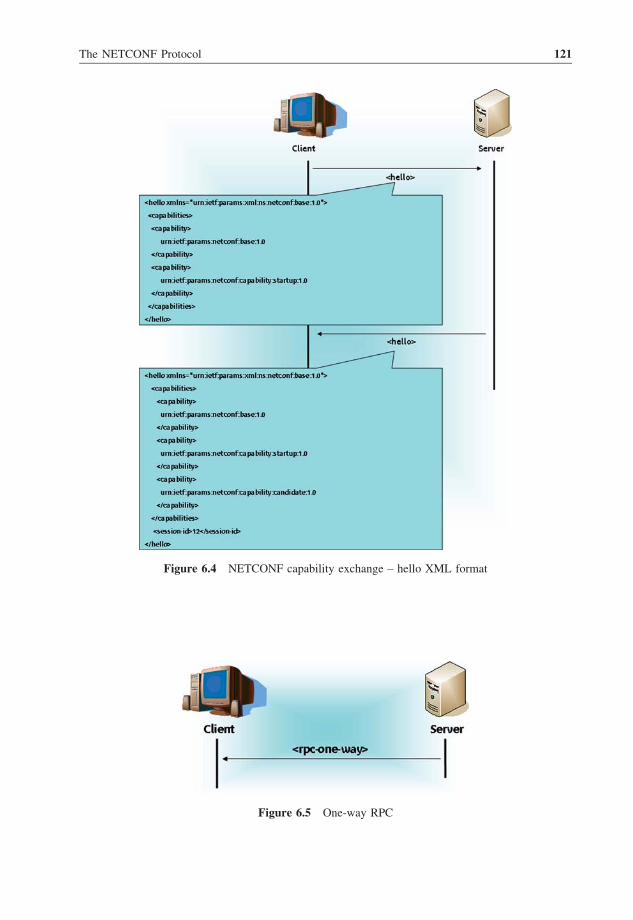
Figure 6.4 NETCONF capability exchange – hello XML format
Figure 6.5 One-way RPC
The NETCONF Protocol 121

Figure 6.6 illustrates an example of the content and the format of an <rpc-one-way>element. In this example, the server sends to the client an event message enclosed in an
<rpc-one-way> element to notify that a configuration task has been enforced. Additional
information on the structure of event notifications is provided in Section 6.3.13.
6.2.7.2 Two-way RPC
NETCONF-enabled nodes use dedicated methods to provide transport-protocol-independent
framing for NETCONF requests and responses between clients and servers. This procedure
is commonly denoted within NETCONF terminology as the RPC communication model.
RPC methods allow NETCONF protocol to be independent of the underlying transport
protocol used to convey communication messages.
The base NETCONF specification documents make use of an RPC scheme that is two-
way, i.e. an RPC request must be answered by an RPC response, as shown in Figure 6.7.
In such a model, two RPC methods can be invoked:
� <rpc>. This method (also referred to as element) is used to carry a NETCONF request
issued from a NETCONF client (also denoted as NETCONF manager) and destined for a
server (also denoted as managed device).
� <rpc-reply>. This element is generated by themanaged device as an answer to a recei ved
<rpc> element. Two categories of RPC response are defined in NETCONF protocol:
– <rpc-error>: this element is enclosed in an <rpc-reply> element and is sent
back to the NETCONF manager if an error or a warning has occurred when processing
an <rpc> element or when enforcing required actions by the managed device;
Figure 6.6 One-way RPC generated by the NETCONF server
122 Service Automation and Dynamic Provisioning Techniques in IP/MPLS Environments

– <ok>: this element is enclosed in an <rpc-reply> element and is sent back to the
client if no errors and no warnings have occurred during the processing of a received
<rpc> element and during the enforcement of required actions by the managed device.
More information about these elements and their usage provided below through several
examples.
6.2.7.3 <rpc> element
An <rpc> element is used to carry a NETCONF request generated by a client and destined
for its attached server. This element, i.e. <rpc>, encloses at least the message-idattribute. The value of this attribute is an arbitrary string assigned by the client. Usually, this
value is a monotonically increasing integer. The XML schema of the message-id attribute
is provided in Table 6.10.
Figure 6.7 provides an example of the content of a basic <rpc> element and its XML
format. The RPC request indicates the URN of the supported NETCONF namespace; in this
example this is indicated by the xmlns line: xmlns¼"urn:ietf:params:xml:ns:netconf:base:1.0".
In this example (Table 6.11), the <rpc> element has a message-id equal to ‘8’. Only
one method is contained in this element. The core of this method is empty. For readers
unfamiliar with XML notations, the ‘!’ symbol is used at the beginning of an XML line to
identify comments. These comments are not part of the definition of the elements, nor are
they considered as attributes, but they provide clarifications and additional useful informa-
tion for the reader of XML documents.
Figure 6.7 Two-way RPC
Table 6.10 XML schema of the message-id attribute
<xs:simpleType name¼"messageIdType"><xs:restriction base¼"xs:string"><xs:maxLength value¼"4095"/>
</xs:restriction></xs:simpleType>
The NETCONF Protocol 123

6.2.7.4 <rpc-reply> element
Upon receipt of an <rpc> element, the server saves the value of the message-id attribute
and uses the corresponding value in any <rpc-reply> message generated as a response to
the received <rpc> element. In addition, if other attributes are present in an <rpc> element, a
NETCONF server returns them in the resulting <rpc-reply> elements without any
modifications, i.e. the values of these attributes are copied by the server and returned back
to the requesting client. If several <rpc> elements have been received by a NETCONF server,
the server processes them serially. Then, the server sends <rpc-reply> elements in the
order the requests were received.
An example of an <rpc-reply> element is shown in Table 6.12.
The <data> tag identifies the part of the <rpc-reply> that contains the data requested
by the method enclosed in a request received by the server. An <rpc-reply> element can
also contain other elements, mainly the <ok> or <rpc-error> elements. These elements
are described in the subsections below.
Table 6.11 Example of an <rpc> element
<rpc message-id¼"8" xmlns¼"urn:ietf:params:xml:ns:netconf:base:1.0"><method-example><!–List of method-example's parameters
–><!– Parameter 1 –><!– Parameter 2 –><!– Parameter 3 –><!– Parameter 4 –>
. . .
. . .<!– Parameter i –><!– Parameter iþ1–>
</ method-example ></rpc>
Table 6.12 Example of an <rpc-reply> element
<rpc-reply message-id¼"8" xmlns¼"urn:ietf:params:xml:ns:netconf:base:1.0"><data><!– Body of data enclosed in the rpc-reply –><tag1>value1</tag1><tag2>value2</tag2><tag3>value3</tag3>
</data></rpc-reply>
124 Service Automation and Dynamic Provisioning Techniques in IP/MPLS Environments

<ok> ElementIn order to inform a remote peer (i.e. one with which a NETCONF session has been
established) that no errors or no warnings have occurred during the processing of a received
<rpc> request, a NETCONF server issues an <ok> element. Table 6.13 provides an
example of the content of an <ok> element.
<rpc-error> ElementWhen an error (or a warning in some NETCONF implementations) has occurred during the
processing of a received <rpc> request, a NETCONF server issues an <rpc-reply>element enclosing an <rpc-error> element. If multiple errors have been encountered by
the server during the processing of the <rpc> request, the server can enclose one or several
<rpc-error> elements in the same <rpc-reply> element. NETCONF implementa-
tions could opt not to send any <rpc-error> element if one or many warnings have
occurred during the processing of the request.
An <rpc-error> element may include the attributes listed in Table 6.14. Optional
attributes can be omitted.
Table 6.15 lists NETCONF errors as defined in the base NETCONF document. For all these
errors, the error severity attribute value is equal to ‘error’ (the corresponding error column is
not represented in the table). Only mandatory attributes are described in Table 6.15.
Tables 6.16 and 6.17 provide two examples illustrating the format of issued <rpc-error> elements. The first example (Table 6.16) illustrates the response sent by the server
in the case where the <rpc> element does not enclose a message-id attribute.
The second example (Table 6.17) shows an <rpc-error> element indicating that the
IP address assigned by the client to one of the server’s interfaces is not valid.
Table 6.13 Example of <ok> element
<rpc-reply message-id¼"8" xmlns¼"urn:ietf:params:xml:ns:netconf:base:1.0">
<ok/></rpc-reply>
Table 6.14 <rpc-error> attributes
error-type Indicates the type of error that has occurred. The following values
can be set: TRANSPORT, RPC, PROTOCOL or APPLICATION.
error-tag A string identifying the error condition.
error-severity Contains a string identifying the error severity, as determined by the
device. This can take the values: error or warning.
error-app-tag Contains a string identifying the data-model-specific or implementation-
specific error condition. This attribute is optional.
error-path Contains an identification of the element path to the node that is
associated with the error being reported in a particular <rpc-error>.This attribute is optional.
error-message This attribute describes the error condition.
error-info Contains protocol-specific or data-model-specific error content.
The NETCONF Protocol 125

Table 6.15 List of NETCONF errors
Error-tag Error-type Error-info Description
IN_USE . PROTOCOL None. The request requires a resource
. APPLICATION None. that is already in use.INVALID_VALUE . PROTOCOL None. The request specifies an
. APPLICATION unacceptable value forat least one parameter.
TOO_BIG . TRANSPORT. RPC None. The request or response
. PROTOCOL is too large.
. APPLICATIONMISSING_ATTRIBUTE . RPC . <bad-attribute>: name of An expected attribute is
the missing attribute; missing.
. PROTOCOL . <bad-element>: name of the
element that should contain
. APPLICATION the missing attribute.
BAD_ATTRIBUTE . RPC . <bad-attribute>: name of the An attribute value is not
attribute with the bad value; correct.
. PROTOCOL . <bad-element>: name of the
element that contains the
. APPLICATION attribute with the bad value.
UNKNOWN_ATTRIBUTE . RPC . <bad-attribute>: name of the An unexpected attribute
unexpected attribute; is present.
. PROTOCOL . <bad-element>: name of the
element that contains the
. APPLICATION unexpected attribute.
MISSING_ELEMENT . RPC <bad-element>: name of the. An expected element is
. PROTOCOL missing element missing.
. APPLICATION
BAD_ELEMENT . RPC . <bad-element>: name of . An element value is
. PROTOCOL the element not correct.
. APPLICATION

UNKNOWN_ELEMENT . RPC . <bad-element>: name of An unexpected element
. PROTOCOL the unexpected element. is present.
. APPLICATION
UNKNOWN_NAMESPACE . RPC Name of the unexpected An unexpected namespace
. PROTOCOL namespace. is present.
. APPLICATION
ACCESS_DENIED . RPC None. Access to the requested RPC,
. PROTOCOL protocol operation or data
. APPLICATION model is denied becauseof authorization failure.
LOCK_DENIED PROTOCOL . <session-id>: session ID of the Access to the requested lock
session holding the requested lock, is denied because it is currently
or zero to indicate a non-NETCONF held by another NETCONF
entity holding the lock. entity.
RESOURCE_DENIED . TRANSPORT None. Request could not be completed
. RPC because of insufficient resources.
. PROTOCOL
. APPLICATION
ROLLBACK_FAILED . PROTOCOL None. Request to roll back some
. APPLICATION configuration change wasnot completed for somereason.
DATA_EXISTS . APPLICATION None. Request could not be completed
because the relevant data model
content already exists.
DATA_MISSING . APPLICATION None. Request could not be completed
because the relevant data model
content does not exist.
(Continued)

OPERATION_NOT_SUPPORTED . RPC None. Request could not be completed
. PROTOCOL because the requested operationis not supported by this
. APPLICATION implementation.
OPERATION_FAILED . RPC None. Request could not be completed
. PROTOCOL because the requested operationfailed for some reason not coveredby any other error condition.
. APPLICATIONPARTIAL_OPERATION APPLICATION . <ok-element>: identifies an
element in the data model
for which the requested operation
has been completed for that node
and all its child nodes; Some part of the requested
. <err-element>: identifies an operation failed.element in the data model forwhich the requested operationhas failed for that node and allits child nodes;
. <noop-element>: identifies anelement in the data model forwhich the requested operationwas not attempted for that nodeand all its child nodes.
Table 6.15 (Continued)
Error-tag Error-type Error-info Description

6.2.8 NETCONF Filtering
6.2.8.1 Terminology
NETCONF protocol allows an application manager to specify which portion of the
configuration and/or state data, as maintained by the managed evice, to be included in a
given <rpc-reply> element. This feature is termed XML subtree filtering and allows
more flexibility to manipulate configuration data (Table 6.18).
NETCONF introduced the following terminology to denote the components that may be
present in a given subtree filter:
Table 6.17 Second example of an <rpc-error>
<rpc-reply message-id ¼``8'' xmlns¼``urn:ietf:params:xml:ns:netconf:base:1.0''><rpc-error>
<error-type>rpc</error-type><error-tag>INVALID_VALUE</error-tag><error-severity>error</error-severity><error-message>Invalid IP Address</error-message>
</rpc-error></rpc-reply>
Table 6.16 First example of an <rpc-error>
<rpc-reply message-id ¼``8'' xmlns¼``urn:ietf:params:xml:ns:netconf:base:1.0''>
<error-type>rpc</error-type><error-tag>MISSING_ATTRIBUTE</error-tag><error-severity>error</error-severity><error-info><bad-attribute>message-id</bad-attribute><bad-element>rpc</bad-element>
</error-info></rpc-error></rpc-reply>
Table 6.18 Example of an XML subtree filter
<filter type¼``subtree''><network xmlns¼``http://serviceauto.org/filters/''><routers/>
</network></filter>
The NETCONF Protocol 129

� Namespace selection. The output when applying this filter is the list of all nodes
defined within the specified namespace. Note that at least one node must be specified
when enclosing this filter in a given NETCONF request. All child nodes will be listed
in the response to be sent back to the application manager. In the example in Table
6.18, all child elements of <network> defined in the namespace http://serviceauto.org/filters/ must be listed in a response to a request enclosing
this filter.
� Containment node. A containment node is a node that contains child elements within a
filter. A containment node can also contain other containment nodes, etc. When only one
containment node is specified in a given filter included in a NETCONF request, all child
nodes must be listed in the response. In the example in Table 6.18, <network> is a
containment node. A request including this filter should be answered by a response
containing all <routers> data.
� Selection node. A leaf element of a subtree filter is called a selection node. In the example
in Table 6.18, the <routers> element is a selection node. When specifying this filter in
a given NETCONF request, the corresponding reply should include all <routers>data.
� Content match node. Any leaf element with simple type content is called a content match
node. More concretely, in the following example, <routerID> is a content match node.
The response to this filter must include only data related to a router with an identifier equal
to ASBR_157485.
6.2.8.2 Examples
In order to illustrate the usage of filters within NETCONF, this section lists numerous
examples (Tables 6.20 and 6.21) and related output when applying the corresponding filter
to a given configuration. The XML document in Table 6.20 is used for all listed examples.
Note that the data model used for these examples is not part of the NETCONF specification
itself.
Table 6.19 Content match node
<filter type¼``subtree''><network xmlns¼``http://serviceauto.org/filters/''><routers><router><routerID>ASBR_157485<routerID>
</router></routers>
</network></filter>
130 Service Automation and Dynamic Provisioning Techniques in IP/MPLS Environments

6.3 NETCONF Protocol Operations
The NETCONF base protocol specifies nine operations. These operations are invoked to
retrieve, install or modify configuration data of a given managed device. These basic
operations are as follows:
� <get>. This method is invoked in order to retrieve both configuration and state data from
a managed device.
� <get-config>. This method is similar to the <get> operation. However, it is used to
retrieve configuration data only.
Table 6.20 Example of an XML configuration
<data><network xmlns¼``http://serviceauto.org/filters/''><routers><router><routerID<ASBR_157485<interfaces><interface><interfaceName<Eth0>/interfaceName><interfaceBW<100M>/interfaceBW>
</interface><interface><interfaceName<Eth1>/interfaceName><interfaceBW<10M>/interfaceBW>
</interface><interface><interfaceName<Eth3>/interfaceName><interfaceBW<100M>/interfaceBW>
</interface></interfaces>
</router><router><routerID<ASBR_787878<interfaces><interface><interfaceName<Eth0>/interfaceName><interfaceBW<10M>/interfaceBW>
</interface><interface><interfaceName<Eth1>/interfaceName><interfaceBW<10M>/interfaceBW>
</interface></interfaces>
</router></routers>
The NETCONF Protocol 131

Table 6.21 Filter examples

(Continued)

Table 6.21 (Continued)

� <copy-config>. This operation is invoked in order to create or to replace all or portion
of the configuration data.
� <edit-config>. This operation is invoked to load all or portions of the configuration data.
� <delete-config>. This method is invoked to delete a configuration datastore.
� <lock> This method is invoked in order to lock a configuration datastore so as to avoid
misconfiguration and inconsistent operations.
� <unlock>. This method is invoked to release locks hold by a NETCONF client on a
configuration datastore.
� <close-session>. This method is used to close gracefully a NETCONF session.
� <kill-session>. This method forces the termination of a NETCONF session.
In addition to the base NETCONF protocol operations, NETCONF peers can invoke
additional methods if appropriate capabilities are supported:
� <validate>. This method is invoked to validate the contents of the specified configuration.
� <commit>. This method is invoked by a client to instruct a server to implement the
candidate configuration data.
� <discard-changes>. This operation is invoked by a NETCONF client if the
candidate configuration should not be committed.
And finally, NETCONF methods introduced in Chisholm et al. [33] in order to support
notification events can also be invoked by NETCONF speakers:
� <subscribe-notification>. This method is issued when a management application
wants to subscribe to a NETCONF notification service.
� <notification>. This method is sent to a management application by a server to
enclose events of interest to the management application.
For each operation, a definition table is provided with the following information:
� Parameters: describes input of the NETCONF method, such as source, target or filter;
� Positive response: describes the output of the NETCONF method to acknowledge the
correct processing of the request;
� Negative response: describes the output of the NETCONF method to indicate that an error
has occurred during the processing of the request.
6.3.1 Retrieve Configuration Data
To retrieve the whole or only part of the configuration datastore of a given managed device,
NETCONF protocol defines a dedicated method called <get-config>. This method is issued
by a management application to the managed device. More information about this method is
captured in Table 6.22.
To illustrate the usage of this method, the example in Figure 6.8 shows a NETCONF
exchange that occurs between a client and a server when retrieving configuration information.
In this example, the client issues a <get-config> operation embedded in an <rpc>element and destined for the managed device. The core body of this operation encloses a
filter specifiying which portion of the configuration data is to be retrieved from the managed
The NETCONF Protocol 135

device. Indeed, the embedded filter, shown in this example, selects retrieving all configured
interfaces in the router (i.e. server).
As a response to this RPC request, the managed device generates an <rpc-reply>response carrying the whole list of configured interfaces. For all listed interfaces, all leaf
Figure 6.8 Example of the <get-config> operation
Table 6.22 <get-config> method
Parameter: source The source element specifies the name of the configuration datastore being
queried.
Filter The filter element identifies the portions of the managed device configuration
to retrieve. If no filter is specified, the entire configuration is returned.
Positive response If the device can satisfy the request, the server sends an <rpc-reply>element containing a <data> element with the results of the query.
Negative response An <rpc-error> element is included in the <rpc-reply> errors,
or problems have been encountered when processing the request
by the managed device.
136 Service Automation and Dynamic Provisioning Techniques in IP/MPLS Environments

configuration elements, such as interface name (interfaceName) and interface band-
width (interfaceBW), are also retrieved from the managed device. Three interfaces
(eth0, eth1 and eth3) are configured in the managed device. Interfaces eth0 and eth3are 100 MB/s Ethernet cards, and eth1 is a 10 MB/s Ethernet card.
6.3.2 Get
Unlike the previous method, the <get> operation is used to retrieve both running
configuration and device state data. <get> and <get-config> have been introduced by
NETCONF to avoid potential problems that can arise when trying to enforce some
unhallowed operation such as writing ‘read-only’ data. Table 6.23 gives more information
about the <get> method.
Figure 6.9 provides an example illustrating the invocation of the <get> method.
Therefore, the client issues an <rpc> element including the <get> method. A filter is
also specified in this request to select the portion of the configuration and state data to be
retrieved from the managed device (server). Within this example, the enclosed filter requests
retrieving information related to the interface whose interfaceName is equal to Eth0.As a response to his request, the server issues an <rpc-reply> element embedding data
related to the interface Eth0. Therefore, the client is notified that Eth0 has a capacity of
100 MB/s. Moreover, this interface has received 155 456 bytes of traffic and sent 871 423
bytes of traffic, and 45 bytes have been dropped.
6.3.3 Delete Configuration Data
In order to delete a configuration datastore, except the <running> configuration one, a
NETCONF client can issue the <delete-config> method. This method is characterized
as in Table 6.24.
To illustrate the usage of the <delete-config> operation, the example in Fig-
ure 6.10 shows the invocation of this method by the client to delete the <startup/>datastore.
As shown in Figure 6.10, the client sends an <rpc> element specifying the datastore to
delete as indicated inside the <target> tag. Upon receipt of this request, the server
enforces appropriate actions so as to delete the <startup/> datastore. A positive answer is
then sent to the client to notify the successful enforcement of the requested action, using the
<ok> method.
Table 6.23 Definition of the <get> operation
Filter This parameter specifies the portion of the managed device configuration
and state data to retrieve. If this parameter is empty, all configuration
and state data are returned.
Positive response If the device can satisfy the request, the server sends an <rpc-reply>element containing a <data> element with the results of the query.
Negative response An <rpc-error> element is included in the <rpc-reply> errors,
or problems have been encountered when processing the request
by the managed device.
The NETCONF Protocol 137

6.3.4 Copy Configuration
The <copy-config> operation is invoked to create or to replace an entire configuration
datastore, specified as a target, with another one, specified as a source. If no configuration
datastore exists, the device creates a new one when invoking the <copy-config> method.
Table 6.25 provides more information about the <copy-config> operation.
Figure 6.11 shows a second example of the <copy-config> operation where the
<running> datastore is replaced by a file located in a given URL. The source file is
Figure 6.9 Example of the <get> operation
Table 6.24 <delete-config definition
Target Target element specifies the name of the configuration datastore to delete.
Positive response If the device was able to satisfy the request, an <rpc-reply> including
an <ok> element is sent to the application manager.
Negative response An <rpc-error> element is included in the <rpc-reply> errors,
or problems have been encountered when processing the request
by the managed device.
138 Service Automation and Dynamic Provisioning Techniques in IP/MPLS Environments

specified in the <source/> element and the target datastore is enclosed in the <target/>element, as shown in Figure 6.11. This operation is embedded in an <rpc> element issued by
the client to the managed device. Upon receipt of this request, and once the operation is
successfully enforced by the server, the latter sends back a positive answer to the client by
invoking the <ok> method which is embedded in an <rpc-reply> element.
6.3.5 Edit Configuration Data
The <edit-config> method is responsible for loading all or portions of the configuration
data. The retrieved configuration data are identified by the <config> attribute. Several
operations can be performed on the specified configuration data as listed below:
Figure 6.10 Example of the <delete-config> operation
Table 6.25 Definition of the <copy-config> operation
Target This element specifies the name of the configuration datastore to use as the
destination of the copy operation.
Source This element specifies the name of the configuration datastore to use as
thesource of the copy operation or the <config> element containing
theconfiguration subtree to copy.
Positive response If the device was able to satisfy the request, an <rpc-reply> including
an <ok> element is sent to the application manager.
Negative response An <rpc-error> element is included in the <rpc-reply> errors,
or problems have been encountered when processing the request
by the managed device.
The NETCONF Protocol 139

� Merge. The configuration data are merged with the configuration at the corresponding
level in the configuration datastore identified by the target parameter (the target parameter
is defined in Table 6.26).
� Replace. The configuration data replace any related configuration in the configuration
datastore identified by the target parameter. Unlike a <copy-config> operation, which
replaces the entire target configuration, only the configuration actually present in the
<config> parameter is affected.
� Create. The configuration data are added to the configuration if and only if the
configuration data do not already exist on the managed device.
� Delete. The configuration data are deleted in the configuration datastore identified by the
target parameter.
Note that the default behavior is the ‘merge’ operation.
Table 6.26 provides additional information about the <edit-config> method.
Figure 6.12 shows an example of the <edit-config>method with the default operation
merge. The management application sends an <edit-config>message so as to set the IP
address of the Eth0 interface to 1.2.3.4. Upon receipt of this message, the managed
device enforces the new configuration and proceeds to setting the IP address of the Eth0interface to the new assigned IP address by the management application. Once all related
actions are enforced, the managed device issues a response to the management application,
acknowledging that the new configuration changes have been taken into account and are
successfully enforced.
Figure 6.11 Example of the <copy-config> operation
140 Service Automation and Dynamic Provisioning Techniques in IP/MPLS Environments

Table 6.26 Definition of the <edit-config operation
Name of the configuration datastore to use as the destination
Parameters Target of the copy operation.
Default operation Selects the default operation for the
<edit-config> request. The
default value for the default operation
parameter is ‘merge’.
Test option The test option element may be specified
only if the device advertizes the :validatecapability. The test option element has
one of the following values:
. test-then-set: perform a validation test
before attempting to set. If validation
errors occur, do not perform the
<edit-config> operation. This
is the default test option;
. set: perform a set without a validation test.
Error option The error option element can take one of
the following values:
. stop-on-error: abort the <edit-config>operation on first error. This is the default
error option.
. continue-on-error: continue to process configuration
data on error. The error is recorded and a negative
response is generated if any errors occur.
. rollback-on-error: if an error occurs, the server
will stop processing the <edit-config>operation and restore the specified configuration
to its complete stateat the start of this
<edit-config> operation. This option requires
the managed device to support the
:rollback-on-error capability.
Config A hierarchy of configuration data as defined by one of
the managed device’s data models.
Positive response If the device was able to satisfy the request, an
<rpc-reply> including an <ok> element is
sent to the application manager.
Negative response An <rpc-error> element is included in the
<rpc-reply> errors, or problems have
been encountered when processing the request
by the managed device.
The NETCONF Protocol 141

6.3.6 Close a NETCONF Session
The method <close-session> is invoked in order to terminate gracefully a NETCONF
session. Upon receipt of a <close-session> request by a NETCONF server, the latter
releases all existing locks and resources associated with the corresponding session. This
method is defined in Table 6.27.
Figure 6.13 provides an example of the usage of the <close-session> method.
Within this example, the client sends an <rpc> element requesting the closure of
NETCONF communication between the managed device and the server. Upon receipt of this
request, the server gracefully closes all alive sessions between the server and client and
releases associated resources. All received NETCONF messages, after treating the
<close-session> operation, are ignored by the server.
Figure 6.12 Example of the <edit-config> operation
Table 6.27 Definition of the <close-session> operation
Parameters None.
Positive response If the device was able to satisfy the request, an <rpc-reply> including
an <ok> element is sent to the application manager.
Negative response An <rpc-error> element is included in the <rpc-reply> errors, or
problems have been encountered when processing the request by the
managed device.
142 Service Automation and Dynamic Provisioning Techniques in IP/MPLS Environments

6.3.7 Kill a Session
The method <kill-session> is used to force terminate a NETCONF session. Upon
receipt of a <kill-session> request by a NETCONF peer, the later will abort any
running operation and will release all existing locks and resources associated with this
session. This method is defined in Table 6.28.
If a NETCONF server receives a <kill-session> request while processing a
confirmed commit, it restores the configuration to its state before the confirmed commit
was issued. Figure 6.14 illustrates how a session can be closed by using the <kill-session> method.
The example in Figure 6.14 shows a client issuing an <rpc> element embedding a
<kill-session> operation. The purpose of this operation is to kill the session identified
by a session-id equal to 15. Upon receipt of this request, the server proceeds to
appropriate actions to handle this request. An <rpc-reply> element is sent back to the
client to notify that no problems have been encountered when processing this request.
Figure 6.13 Example of the <close-session> operation
Table 6.28 Definition of the <kill-session> method
Parameters Session identifier of the NETCONF session to be terminated. If this value is
equal to the current session ID, an ‘invalid value’ error is returned.
Positive response If the device was able to satisfy the request, an <rpc-reply> including
an <ok> element is sent to the application manager.
Negative response An <rpc-error> element is included in the <rpc-reply> errors,
or problems have been encountered when processing the request
by the managed device.
The NETCONF Protocol 143

6.3.8 Lock NETCONF Sessions
NETCONF protocol uses the <lock> operation in order to lock a configuration datastore
and deny the modification of the configuration to other NETCONF clients. A server
accepting a lock operation should allow only the client holding the lock to modify the
configuration data and should send back appropriate error messages to clients trying to
modify the locked configuration datastore.
Table 6.29 provides more information about the definition of this method.
A first example illustrating the usage of the <lock> operation is provided in Figure 6.15.
This method is carried inside an <rpc> element issued by the client and destined for the
managed device. This request specifies the datastore to be locked. Upon receipt of this
request, the server checks if the <candidate> datastore is not locked by another client. In
this example, the <running> datastore is not locked; therefore, the server accepts the
request, proceeds to enforcing appropriate actions to lock the <running> datastore and
Table 6.29 Definition of the <lock> operation
Target This element specifies the name of the configuration datastore to lock.
Positive response If the device was able to satisfy the request, an <rpc-reply> including
an <ok> element is sent to the application manager.
Negative response An <rpc-error> element is included in the <rpc-reply> errors,
or problems have been encountered when processing the request by the
managed device. If the lock is already held by another client, the
<error-tag> element will be set to ‘lock denied’, and the
<error-info> element will include the <session-id> of the
lock owner. If the lock is held by a non-NETCONF entity, a
<session-id> of 0 is included.
Figure 6.14 Example of the <kill-session> operation
144 Service Automation and Dynamic Provisioning Techniques in IP/MPLS Environments

assigns the lock to the requesting client. An <rpc-reply> including an <ok> element is
then sent to the client.
A second example (Figure 6.16) provides an overview of the NETCONF exchange that
occurs when errors are encountered when processing a lock request. Upon receipt of the
request by the server, the latter proceeds to appropriate checking regarding the locks
associated with the <candidate> datastore. In this example, the <running> datastore is
already locked by another client. Therefore, the server issues an rpc-reply> with an
appropriate error message to notify the client that its request is denied.
6.3.9 Unlock NETCONF Sessions
In order to release a configuration lock, the <unlock> operation can be invoked by a given
management application. A client is only allowed to unlock a configuration datastore it has
previously locked.
Table 6.30 provides additional information about the <unlock> operation.
A first example illustrating a successful <unlock> operation is shown in Figure 6.17. In
this example, the client issues a request including an <unlock> operation together with the
targeted datastore. This request is received by the server. The latter handles the received
request by enforcing appropriate actions and checking operation. After verifying that this
client holds a lock on the <running> datastore, the server releases this lock and sends back
an <rpc-reply> embedding an <ok> method to notify the client about the successful
handling of its request. Consequently, the <running> datastore is no longer locked and is a
candidate to be locked by any other management application.
The second example (Figure 6.18) illustrates the exchange of NETCONF messages that
occurs when a client tries to unlock a configuration datastore that has been locked by another
NETCONF client. The server notifies the client about the failure of its request and lists the
reasons for its failure in the response embedded in a <rpc-reply> element.
Figure 6.15 Example of the <lock> operation
The NETCONF Protocol 145

6.3.10 Validate Configuration Data
To validate the content of a given configuration, a managed application can issue the
<validate> method specifying the targeted configuration datastore to be validate. This
method is defined in Table 6.31.
Figure 6.19 provides an example illustrating the usage of the <validate> operation. In
this example, the client sends an <rpc> request containing a <validate> operation. The
target datastore is the candidate configuration one. Upon receipt of this request, the server
proceeds to appropriate actions and enforces them so as to validate the candidate config-
uration. Once these actions are successfully enforced, the server issues an <rpc-reply>element destined for the client, including an <ok> method. This response acknowledges to
the client that validation-related actions have been executed on the candidate configuration
datastore.
Figure 6.16 Example of the <lock> operation with an error message
Table 6.30 Definition of the <unlock> operation
Target This element specifies the name of the configuration datastore to unlock.
Positive response If the device was able to satisfy the request, an <rpc-reply> including
an <ok> element is sent to the application manager.
Negative response An <rpc-error> element is included in the <rpc-reply> errors,
or problems have been encountered when processing the request
by the managed device.
146 Service Automation and Dynamic Provisioning Techniques in IP/MPLS Environments

Figure 6.17 Example of the <unlock> operation
Figure 6.18 Example of the <unlock> operation with errors
The NETCONF Protocol 147

6.3.11 Commit Configuration Changes
A NETCONF client instructs a server to implement the candidate configuration data by
invoking the <commit> method. This method is allowed only if the :candidatecapability is supported by both NETCONF peers. The running configuration datastore
must remain unchanged if the NETCONF managed device was unable to commit all the
changes in the candidate configuration datastore.
Table 6.32 defines the <commit> operation.
Figure 6.20 shows an example of the usage of the <commit> method. This method is
enclosed in an <rpc> element sent by the client to the server. Once this request is received
by the server, the latter implements the changes that have been added to the candidate
configuration and issues a response to the client acknowledging that all commit-related
operations have been achieved and changes implemented with the managed device.
Table 6.31 Definition of <validate> operation
Source This element specifies the name of the configuration datastore being
validated.
Positive response If the device was able to satisfy the request, an <rpc-reply> including
an <ok> element is sent to the application manager.
Negative response An <rpc-error> element is included in the <rpc-reply> errors,
or problems have been encountered when processing the request
by the managed device. A <validate> operation can fail for
any of the following reasons:
� syntax errors;
� missing parameters;
� references to undefined configuration data.
Figure 6.19 Example of the <validate> operation
148 Service Automation and Dynamic Provisioning Techniques in IP/MPLS Environments

6.3.12 Discard Changes of Configuration Data
A <discard-changes> method can be invoked by a given NETCONF client if the
candidate configuration should not be committed. Therefore, the candidate configuration is
reverted to the current running configuration. This operation discards any uncommitted
changes by resetting the candidate configuration with the content of the running configura-
tion. This method is only invoked when the :candidate capability is supported by both
NETCONF peers (i.e. management application and managed device).
Figure 6.21 provides an example of the usage of the <discard-changes> method.
Once the <discard-changes> method is received by the server, the latter will proceed
to revert the content of the candidate configuration to the content of the running configura-
tion datastore. An <rpc-reply> response including an <ok> method is then sent to the
client as illustrated in Figure 6.21.
6.3.13 NETCONF Notification Procedure
Within the NETCONF architecture, managed devices can send notification messages when
requested by NETCONF management applications. The NETCONF notification procedure
is illustrated in Figure 6.22.
Table 6.32 Definition of the <commit> operation
Parameters None.
Positive response If the device was able to satisfy the request, an <rpc-reply> including
an <ok> element is sent to the application manager.
Negative response An <rpc-error> element is included in the <rpc-reply> errors,
or problems have been encountered when processing the request
by the managed device.
Figure 6.20 Example of the <comit> operation
The NETCONF Protocol 149

Firstly, the transport session is established and capabilities are exchanged between two
NETCONF peers. Then, the client sends a <create-subscription> to the server to
specify the event class of interest. When an event belonging to the class to which the client
has subscribed occurs, the server sends <notification> messages to the client. These
Figure 6.21 Example of the <discard-changes> operation
Figure 6.22 Notification procedure
150 Service Automation and Dynamic Provisioning Techniques in IP/MPLS Environments

notification messages enclose information about the occurring event. In the first version of
the document [33], notification subscriptions can be modified during the lifetime of a
NETCONF session owing to the invocation of a <modify-subscription> method.
This feature has been dropped in the latest version of that document.
6.3.13.1 Subscribing to Event Notifications
In order to subscribe to an event notification, which consists in receiving asynchronous event
notifications from the server, a NETCONF client sends a <create-subscription>method to a managed device. The client indicates to the server the type of event notification
it wishes to receive through the ‘stream’ attribute.
This method is defined in Table 6.33.
Figure 6.23 shows the format of a <create-subscription> method. In this
example, the client sends a subscription request to be notified of events belonging to a
given event class. The server accepts the request and sends an <ok> element to the client to
indicate that the subscription is accepted.
Table 6.33 Definition of the <create-subscription> operation
Stream Indicates which event classes are of interest to the client. If not present,
events of all classes will be sent to the client.
Positive response If the device was able to satisfy the request, an <rpc-reply> including
an <ok> element is sent to the application manager.
Negative response An <rpc-error> element is included in the <rpc-reply> errors,
or problems have been encountered when processing the request
by the managed device.
Figure 6.23 Example of <create-subscription>
The NETCONF Protocol 151

6.3.13.2 Sending an Event Notification
Once a management application has subscribed to event classes of interest, the managed
device sends asynchronously notification messages, denoted as <notification>, to that
management application. Notification messages are one-way RPCs and do not require any
response from the management application. In order to retrieve available event classes as
supported by the managed device, the management application has to issue a <get> method
as illustrated in Figure 6.24.
In this example, the management application issues a <get> operation enclosing a filter
specifying the portion of data to be retrieved from the managed device. This filter specifies
showing the list of event streams as supported by the managed device. As a response to this
request, the managed device sends back to the management application an <rpc-reply>containing two event classe. The first class, the default one, is called NETCONF. This class
supports the notification replay feature. The second event class is called SNMP. This second
class does not support notification replay because the tag is set to false.
6.3.13.3 Terminating a Notification Subscription
To terminate a subscription to an event notification, a management application should issue a
<kill-session> method or terminate the transport session. Under normal condition, i.e.
Figure 6.24 Retrival of event classes
152 Service Automation and Dynamic Provisioning Techniques in IP/MPLS Environments

the NETCONF session is active, the subscription notification terminates when the ‘stop
time’ as indicated in the <create-subscription> message is reached.
6.4 NETCONF Transport Protocol
6.4.1 NETCONF as Transport-independent Protocol
NETCONF protocol is a transport-independent protocol. Therefore it can be activated using
any transport protocol that satisfies a set of requirements, which are listed below:
� Connection oriented transport protocol. NETCONF is connection oriented, requiring a
persistent connection between NETCONF peers.
� Authentication and integrity mechanisms should be supported by the transport protocol.
NETCONF protocol requires secure channels to convey sensitive data and means to
validate the identity of the remote NETCONF peer. NETCONF protocol recommends the
support of RADIUS the remote access dial-in user server (RADIUS) (RFC 2865 [35]),
transport layer security (TLS) (RFC 2246 [36]) and SSH.
Nevertheless, NETCONF requires that any NETCONF implementation must support
the SSH transport protocol mapping as a transport protocol. NETCONF implementa-
tions can support any additional transport protocol that meets the aforementioned
requirements.
In Section 6.4.2, we provide more information about the mapping of using BEEP, SSH
and SOAP as NETCONF transport protocols. Note that the purpose of this section is not to
provide technical details about SSH, BEEP and SOAP but only to describe how NETCONF
is invoked over these transport protocols.
6.4.2 Transport Protocol Alternatives
6.4.2.1 SSH3
This section describes how NETCONF is mapped to the SSH connection protocol (RFC
4254 [16]) over the SSH transport protocol (RFC 4253 [15]). We assume that the reader is
familiar with the SSH system. For readers who want to have detailed knowledge about SSH,
please refer to Refs [9], [12] and [14] to [16].
Where is Secure Shell Being Standardized?The first version of SSH (aka SSH1) protocol was released in 1995. This first version
provides secure means for interactive applications such as Telnet, RSH, REXEC or
RLOGIN. This version has been updated within the IETF on account of some security
failures. This work has been conducted by the SECSH working group (http://www.ietf.org/
html.charters/secsh-charter.html). Several RFCs have been edited by this working group,
especially the second version of SSH (aka SSH2).
3The reference SSH website is available at www.openssh.org
The NETCONF Protocol 153

The RFCs published by the SECSH working group are listed below:
� The secure shell protocol assigned numbers (RFC 4250 [12]);
� The secure shell protocol architecture (RFC 4251 [13]);
� The secure shell authentication protocol (RFC 4252 [14]);
� The secure shell transport layer protocol (RFC 4253 [15]);
� The secure shell connection protocol (RFC 4254 [16]);
� Using DNS to securely publish secure shell key fingerprints (RFC 4255 [17]);
� Generic message exchange authentication for the secure shell protocol (RFC 4256 [18]);
� The secure shell transport layer encryption modes (RFC 4344 [19]);
� Secure shell session channel break extension (RFC 4335 [20]).
The following IETF Drafts has been adopted by the SECSH working group:
� SSH file transfer protocol (draft-ietf-secsh-filexfer);
� GSSAPI authentication and key exchange for the secure shell protocol (draft-ietf-secsh-
gsskeyex);
� SSH public key file format (draft-ietf-secsh-publickeyfile);
� Diffie–Hellman group exchange for the SSH transport layer protocol (draft-ietf-secsh-dh-
group-exchange);
� Uniform resource identifier scheme for secure file transfer protocol (SFTP) and secure
shell (draft-ietf-secsh-scp-sftp-ssh-uri);
� Secure shell public-key subsystem (draft-ietf-secsh-publickey-subsystem);
� X.509 authentication in SSH (draft-ietf-secsh-x509).
What is SSH?SSH is a security protocol used for secure remote login over a public/shared network. The
SSH system is structured as follows:
� The transport layer. This layer provides server authentication, confidentiality and
integrity. The transport layer is usually used over TCP. An example of SSH transport
message exchange is provided in Figure 6.25. The main steps that occur during an SSH
transport session are:
– TCP connection setup. The client initiates the connection to the server which listens on
port 22.
– SSH version string exchange. Both sides send a version string. The current SSH
protocol version is 2.0. This negotiation is used to indicate the capabilities of an
implementation and to trigger compatibility extensions.
– SSH key exchange. The encryption algorithm is negotiated. SSH2 supports several
algorithms such as 3des-cbc, blowfish-cbc, twofish256-cbc, twofish128-cbc, aes192-cbc and serpent192-cbc. Note that the encryption algorithm can
be different for each direction.
– After this stage, SSH data can be exchanged between two SSH peers.
– SSH sessions can be closed by invoking appropriate SSH messages.
� User authentication protocol. This protocol is responsible for authenticating the client to
the server. It runs over the transport layer protocol. An example of user authentication
154 Service Automation and Dynamic Provisioning Techniques in IP/MPLS Environments

message exchange is provided in Figure 6.26. Definitions of these functions are not
provided in this book; for more information about the content of exchanged SSH
messages, please refer to SSH base documents. This service is also denoted as sshuserauth.
� The connection protocol. This protocol multiplexes the encrypted tunnel into several
logical channels. This layer runs over the user authentication protocol. Note that channels
are identified by channel numbers at both ends of the connection and that channel numbers
for the same channel at the client and server sides may differ.
Figure 6.25 SSH Transport connection setup
Figure 6.26 SSH user authentication protocol
The NETCONF Protocol 155

Initiating NETCONF Sessions over SSHTo run NETCONF over SSH, the following steps should be followed:
1. The NETCONF client establishes an SSH transport connection using the SSH transport
protocol.
2. The NETCONF client and NETCONF server exchange keys for message integrity and
encryption purposes.
3. The NETCONF server invokes the ssh userauth service to authenticate the client.
4. The NETCONF client invokes the SSH connection protocol (this step is also denoted as
the ssh-connection service).
5. After the ssh-connection service is established, the client opens a channel that will
result in a SSH session.
6. Once the SSH session has been established, the user will invoke NETCONF as an SSH
subsystem.
Exchanging NETCONF Methods over SSHOnce a NETCONF session over SSH has been established, NETCONF methods can be
exchanged between NETCONF peers as described in previous sections. Nevertheless, the
special character sequence ‘]]<]]>’ is sent by the client and the server after each XML
document. This character sequence is used to identify the end of an XML document. The
motivation behind the use of this ‘illegal’ XML character is to ease synchronisation of the
client and the server in the case of an error.
Figures 6.27 and 6.28 provide two examples of NETCONF exchange messages. In the first
example, Figure 6.27 illustrates the capability exchange that occurs after NETCONF session
establishment. The second example (Figure 6.28) provides an example of a NETCONF
operation (in this example the <copy-config> method) sent over SSH. These NETCONF
elements are ended by ‘]]<]]>’ characters.
6.4.2.2 BEEP
Where was BEEP Designed?4
The BEEP protocol was specified within the BEEP working group, which disbanded in
March 2002. The main goal of that working group was to develop a standards-track
application protocol framework for connection-oriented, asynchronous request/response
interactions. The challenge of this protocol design was that the designed framework had
4Several implementations of BEEP protocol are available. Examples of these implementations are as follows:
� wodBeep: an ActiveX implementation of the BEEP protocol;
� beepcore-c: C/C++ implementation of RFC 3080 [21] and RFC 3081 [22];
� beepcore-java: Java implementation of RFC 3080 [21] and RFC 3081 [22];
� beepcore-tcl: Tcl implementation of RFC 3080 [21] and RFC 3081 [22];
� BEEPy: a python implementation of RFC 3080 [21] and RFC 3081 [22];
� IBM BeepLite: BEEP implementation written in Java;
� Net::BEEP::Lite: a Perl BEEP implementation;
� PermaBEEP-Java: a toolkit for writing Java-based applications that use the BEEP framework;
� RoadRunner BEEP Framework: open source BEEP implementation written in C;
� JsBEEP: JavaScript implementation of the BEEP protocol.
156 Service Automation and Dynamic Provisioning Techniques in IP/MPLS Environments

to permit multiplexing of independent request/response streams over a single transport
connection and had to support both textual and binary messages. The BEEP working group
produced two RFCs:
� The blocks extensible exchange protocol core (RFC 3080 [21]);
� Mapping the BEEP core onto TCP (RFC 3081 [22]).
We also recommend reading the following RFC, which is not an output of the BEEP WG
but provides much more information about application protocols:
� On the design of application protocols (RFC 3117 [23]).
Figure 6.27 Example of capability exchange over SSH
The NETCONF Protocol 157

What is BEEP?5
BEEP is a framing mechanism allowing simultaneous and independent exchanges of
messages between two nodes. BEEP defines the concept of channel where all exchanges,
such as transport security, user authentication and data exchange, occur.
BEEP supports the mechanisms shown in Table 6.34.
Figure 6.28 Example of the <copy-confing> operation over SSH
5The original name of the BEEP protocol was BXXP (the Blocks eXtensible eXchange Protocol).
Table 6.34 BEEP mechanisms
Mechanism BEEP
Framing Counting with a trailer
Encoding MIME or text/xml
Reporting Three-digit and localized textual diagnostic
Asynchrony Channels
Authentication SASL (RFC 2222 [37])
Privacy SASL or TLS (RFC 2246 [36])
158 Service Automation and Dynamic Provisioning Techniques in IP/MPLS Environments

BEEP defines the following messages:
� MSG. This message is used to send a request asking the server to perform a given task.
� RPY. This message is sent back by the server to inform the client that the requested task
has been completed.
� ERR. This message is sent back by the server to inform the client that an error has
occurred during the execution of the requested task.
NETCONF over BEEPTo enable NETCONF over BEEP, the following steps should be followed (see Figure 6.29):
1. A BEEP session is established between the NETCONF client and the server.
2. The NETCONF client advertizes the NETCONF profile to the server, as illustrated in
Figure 6.30.
3. NETCONF capabilities are exchanged between the client and the server, as illustrated in
Figure 6.31. Each NETCONF peer sends its capabilities, which should be positively
acknowledged by the remote peer.
4. Once capabilities are exchanged, the NETCONF client can send NETCONF methods to
the server. These methods are encoded in RPC elements.
For more information about BEEP-related messages, refer to the BEEP base specifica-
tions.
6.4.2.3 SOAP
Where is SOAP Standardized?SOAP is a recommendation of W3C (World Wide Web Consortium, URL: http://www.w3.
org). W3C initiated the SOAP initiative in 1999. When the SOAP 1.0 version was released, it
Figure 6.29 NETCONF over BEEP
The NETCONF Protocol 159

Figure 6.30 NETCONF over BEEP: starting a BEEP channel
Figure 6.31 NETCONF over BEEP: exchange of capabilities
160 Service Automation and Dynamic Provisioning Techniques in IP/MPLS Environments

was based only on HTTP. However, in May 2000, SOAP 1.1 was released and included other
transport protocols. Then, the first draft of SOAP 1.2 was presented in July 2001 and
promoted to a ‘recommendation’. The following URLs provide a list of literature about
SOAP and XML-related effort:
� http://www.w3.org/TR/soap12-part0/;
� http://www.w3.org/TR/soap12-part1/;
� http://www.w3.org/TR/soap12-part2/;
� http://www.w3.org/2000/09/XML-Protocol-Charter;
� http://www.w3.org/2002/ws/Activity.html;
� http://www.w3.org/TR/xmlp-reqs/;
� http://www.w3.org/TR/xmlp-am/;
� http://www.w3.org/TR/xmlp-scenarios/.
What is SOAP?SOAP provides means for exchanging XML-encoded information. It defines a framework
for messages that can be exchanged over a variety of underlying protocols such as HTTP or
BEEP. The format of SOAP messages is shown in Figure 6.32.
Figure 6.32 Format of SOAP message
The NETCONF Protocol 161

Table 6.35 provides an example of the content of a SOAP message.
NETCONF over SOAPTwo alternatives can be taken into account in order to initiate a NETCONF session over
SOAP:
� If SOAP is used with HTTP, then the client sends a POST method to the NETCONF server
identified by an URI.
� If SOAP is used over BEEP, then the SOAP profile should be advertized over a BEEP
session as specified in the above BEEP section. Then the NETCONF can be initiated.
Once a NETCONF session is established, capabilities can be exchanged between the
client and the server. In the case of SOAP over HTTP, the client must send its <hello>message first. Figure 6.33 provides an example of the capability exchange that occurs.
After the capability exchange phase, the client can send a NETCONF request to the
server. These requests are encoded in RPC and enclosed in a SOAP message.
6.5 NETCONF Capabilities
As mentioned in Section 6.2.6, the NETCONF protocol defines a set of capabilities that can
be supported by a NETCONF speaker, either a client or a server. The implementation of
these capabilities is optional, and, if supported, a NETCONF node should advertize them to
its NETCONF peers. Upon receipt of this advertisement, a remote NETCONF peer uses only
the capabilities it understands and ignores the ones it does not. In this section, a list of
capabilities and their definitions are provided.
For each capability presented, the following information is provided:
� Dependencies: indicates if the support of a capability depends on the support of another
capability;
� Capability identifier: provides the identifier of the capability;
Table 6.35 Example of a SOAP message
<env:Envelope xmlns:env¼"http://www.w3.org/2003/05/soap-envelope"><env:Header><n:alertcontrol xmlns:n¼"http://example.org/alertcontrol"><n:priority>1</n:priority><n:expires>2025-12-21T03:34:34-05:00</n:expires></n:alertcontrol></env:Header><env:Body><m:alert xmlns:m¼"http://example.org/alert"><m:msg>EXAMPLE EXAMPLE EXAMPLE EXAMPLE</m:alert></env:Body></env:Envelope>
162 Service Automation and Dynamic Provisioning Techniques in IP/MPLS Environments

� Modifications to existing operations: lists the modifications to NETCONF operations
when the capability is supported.
6.5.1 URL Capability
A NETCONF device advertizing the support of :url capability has the ability to accept the
<url> element in <source> and target> parameters. The capability is identified by URL
Figure 6.33 Example of capabilities exchange over SOAP
The NETCONF Protocol 163

arguments indicating the supported URL schemes such as the file transfer protocol (FTP),
the hypertext transfer protocol (HTTP), the trivial file transfer protocol (TFTP), etc.
The :url capability is characterized as described in Table 6.36.
The example illustrated in Figure 6.34 showsshows the usage of the <url> element
inside a <copy-config> operation. In this example, the managed device is asked to replace
Table 6.36 URL capability
Dependencies None.
Capability identifier urn:ietf:params:netconf:capability:url:1.0?scheme¼{name,...}where the ‘scheme’ argument is assigned to
a comma-separated list of scheme names supported by the NETCONF
peer such as ftp, http, etc.
Modifications to . <edit-config> can accept the <url> element as an alternative
existing operations to the <config> parameter. If the <url> element is specified,
then it should identify a local configuration file;
. can accept the <url> element as the value of the <source>and the <target> parameters;
. can accept the <url> element as the value of the <target>parameters. If this parameter contains an URL, then it should
identify a local configuration file;
. <validate> can accept the <url> element as the value of the
<source> parameter.
Figure 6.34 Example of <copy-config> with <url> element
164 Service Automation and Dynamic Provisioning Techniques in IP/MPLS Environments

its running configuration datastore with the content of the file located in the indicated
URL.
6.5.2 XPath Capability
A NETCONF device advertising the support of :xpath capability ensures its ability to
accept the use of XPath expression [38] in the filter element. The XPath expression is
evaluated in a context where the context node is the root node, and the set of namespace
declarations are those in scope of the filter element, including the default namespace.
This capability is described in Table 6.37.
The following example shows an example of usage of the XPath expression in the filter
element of the <get> operation. The example illustrated in Figure 6.35 captures a
NETCONF call flow between a client and a server. The server is asked to retrieve both
state and configuration data related to the session initiation protocol (SIP) channel as
Table 6.37 XPath capability
Dependencies None.
Capability identifier urn:ietf:params:netconf:capability:xpath:1.0Modifications to <get-config> and <get> can accept the value xpath in the
existing operations type attribute of the filter element. When the type attribute is set to
xpath, the contents of the filter element will be treated as an
XPath expression and used to filter the returned data.
Figure 6.35 Example of <get> with Xpath in the filter element
The NETCONF Protocol 165

configured in an asterisk VoIP server (www.asterisk.org). The managed device returns the
content of the ‘SIP.conf’ file and associated state data related to the SIP channel.
6.5.3 Writable-Running Capability
A NETCONF device can advertize its support of :writable-running capability if this
device supports ‘write’ operations on the <running> configuration datastore.
Table 6.38 provides more information about this capability.
As indicated in Table 6.38, a device that supports the :writable-running capability
can invoke the <edit-config> and <copy-config> operations with <running>configuration as target (e.g. see Figure 6.36 see which illustrates an example of
the <edit-config> operation invoked with <running> as a target configuration
datastore).
Table 6.38 Writable-running capability
Dependencies None.
Capability identifier urn:ietf:params:netconf:capability:writable-running:1.0
Modifications to <edit-config> and <copy-config> operations can accept the
existing operations <running> element as a <target>.
Figure 6.36 Example of <copy-config> with <running> as a target
166 Service Automation and Dynamic Provisioning Techniques in IP/MPLS Environments

6.5.4 Candidate Configuration Capability
A NETCONF device can advertize that it supports the :candidate capability if a
<candidate> configuration datastore is available on this device. NETCONF operations
can be invoked with the <candidate> configuration datastore as <target> or
<source> elements. A <commit> operation may be performed in order to set the
device’s running configuration to the value of the candidate configuration. The client can
discard any uncommitted changes to the candidate configuration by executing the <dis-card-changes> operation. Note that a <candidate> configuration datastore may be
shared among several NETCONF sessions. However, it is suitable for a client to lock the
<candidate> configuration datastore before modifying it.
Table 6.39 provides more information about this capability.
Figure 6.37 provides an example of the usage of <candidate> as a target for <lock>and <unlock> operations.
6.5.5 Confirmed Commit Capability
The :confirmed-commit capability indicates that the server supports the <confirmed>and <confirm-timeout> parameters which can be enclosed in a <commit> operation.
The timeout period can be adjusted with the <confirm-timeout> element. The default
value of this timeout is 600 seconds.
The NETCONF server must restore the configuration to its state before the confirmed
commit was issued in the following cases:
� The session issuing the confirmed commit is terminated before the confirm timeout
expires.
� The managed device reboots for any reason before the confirm timeout expires.
� A confirming commit is not issued.
Table 6.40 provides more precise details about this capability.
Figure 6.38 shows an example of usage of the <commit> operation. In this example, the
management application sends an <rpc> request in order to set the commit timeout to 300
seconds.
Table 6.39 Candidate capability
Dependencies The : confirmed-commit capability is only relevant if the :candidate
capability is also supported.
Capability identifier urn:ietf:params:netconf:capability:candidate:1.0
Modifications to . The candidate configuration can be used as a source or target of any
existing operations <get-config>, <edit-config>, <copy-config> or
<validate> operations.
. The candidate configuration can be locked or unlocked using the
<lock>/<unlock> operation with the <candidate>element as the <target> parameter.
The NETCONF Protocol 167

6.5.6 Validate Capability
The support of the :validate capability means that a NETCONF node can perform
checking operations on a candidate configuration for syntactical and semantic errors before
the enforcement of the configuration. If this capability is supported, the device supports the
<validate> operation and checks at least for syntax errors.
Table 6.41 provides more precise details about this capability.
Refer to Section 6.3 for an example of the usage of the <validate> operation.
Figure 6.37 Example of <lock> and <unlock> operations with <candidate> as a target
Table 6.40 Confirmed commit capability
Dependencies The :confirmed-commit capability is only relevant if the :candidate capability is also supported.
Capability identifier urn:ietf:params:netconf:capability:confirmed-commit:1.0
Modifications to The :confirmed-commit capability allows two additional
existing operations parameters to the <commit> operation:
. confirmed: perform a confirmed commit operation;
. confirm timeout: timeout period for confirmed commit, in seconds.
If unspecified, the confirm timeout defaults to 600 seconds.
168 Service Automation and Dynamic Provisioning Techniques in IP/MPLS Environments

6.5.7 Distinct Startup Capability
ANETCONF device can advertize that it supports the :startup capability if a <startup>configuration datastore is available on this device. In order to update the <startup>configuration datastore to the current <running> configuration, a <copy-config> opera-
tion must be issued. Table 6.42 provides more information about this capability.
Figure 6.38 Example of <commit> with <confirm-timeout> as a target
Table 6.41 Validate capability
Dependencies None.
Capability identifier urn:ietf:params:netconf:capability:validate:1.0
Modifications to None.
existing operations
Table 6.42 Distinct startup capability
Dependencies None.
Capability identifier urn:ietf:params:netconf:capability:startup:1.0Modifications to The :startup capability adds the <startup/> configuration
existing operations datastore to arguments of several NETCONF operations. The server
must support <startup> being used as a <source> parameter for
<get-config> and also for <validate> if :validate capability is
supported, as <target> for <lock> and <unlock> and as both
<source> and <target> for <copy-config>.
The NETCONF Protocol 169

Figure 6.39 provides an example of invoking a <copy-config> method to update the
content of the <startup> configuration with the content of the running configuration.
6.5.8 Rollback on Error Capability
A NETCONF device advertizing the support of :rollback-on-error capability can
indicate a rollback-on-error value in the <error-option> parameter response to
received <edit-config> operations.
Table 6.43 provides some information about this capability.
Figure 6.39 Example of <copy-config> with <startup> as a target
Table 6.43 Rollback on error capability
Dependencies None.
Capability identifier urn:ietf:params:netconf:capability:rollback-on-error:1.0
Modifications to <edit-config> can have a rollback-on-error value to
existing the <error-option> parameter
170 Service Automation and Dynamic Provisioning Techniques in IP/MPLS Environments

6.5.9 Notification Capability
The support of notification capability by a given managed device denotes its ability to send
event information, statistical data and other changes to applications that subscribed to this
service. Other criteria may be enclosed in the notification subscription in order to select
event classes of interest to the management application.
Table 6.44 provides some information about this capability.
6.6 Configuring a Network Device
This section provides some guidelines when configuring a network device. It also
describes NETCONF operations that should be invoked for correct configuration beha-
viors. Figure 6.40 presents a NETCONF client communicating with a network device via
a NETCONF channel over one of the available transport protocols (SSH, BEEP or SOAP).
In order to configure this network device, the following tasks should be performed by the
management application, in this order:
1. Acquiring the configuration lock. In order to avoid configuration inconsistency, it is
recommended, for a NETCONF client desiring to configure a network device, to acquire
the lock on the configuration datastore. This is achieved by invoking the <lock>method, as illustrated in example 1 presented in Figure 6.41.
2. Loading the update. Then the new configuration can be loaded onto the network device,
as illustrated in example 2 of Figure 6.41. If the :candidate capability is supported, it
is recommended that the candidate datastore be used as a target parameter of NETCONF
operations, as illustrated in example 1 of Figure 6.42.
3. Validating the incoming configuration. When the configuration is loaded or the candidate
datastore is modified, the client is invited to invoke the <validate> method, as
illustrated in example 3 of Figure 6.41 or in example 2 of Figure 6.42.
Table 6.44 Notificiation capability
Dependencies None.
Capability identifier urn:ietf:params:netconf:capability:notification:1.0
Modifications to <subscribe-notification> and <notification>existing operations are supported by the managed device.
Figure 6.40 Configuration use case
The NETCONF Protocol 171

4. Saving the running configuration. In order to avoid misconfiguration, it is recommended
that the running datastore be saved before enforcing the new configuration so as to be able
to regress to the previous device operating state. This operation can be achieved by
invoking the <copy-config> method, as illustrated in example 4 of Figure 6.41.
Figure 6.41 Set of NETCONF operations to configure a network device (:candidate and :confirmed-commit capabilities are not supported)
Figure 6.42 Set of NETCONF operations to configure a network device
172 Service Automation and Dynamic Provisioning Techniques in IP/MPLS Environments

5. Changing the running configuration. Once the running configuration datastore is saved,
the client is invited to invoke the <edit-config> so as to apply the new configuration
or to promote the candidate datastore to the running datastore via a <commit> method.
See example 5 in Figure 6.41 or example 3 in Figure 6.42.
6. Testing the new configuration. When the new configuration is promoted to running state,
the manager should test the behavior of the device and conclude if the new configuration
is valid or not.
7. Making the change permanent. When performed tests have confirmed that the behavior of
the device is as expected, the running datastore is copied to the startup datastore, as
shown in example 7 in Figure 6.41 or in example 4 in Figure 6.42.
8. Releasing the configuration lock. Once all configuration tasks have been performed, the
lock should be released. See example 8 in Figure 6.41.
6.7 NETCONF Content Layer
The NETCONF protocol separates protocol operations from data models. Data model design
is clearly beyond the scope of the NETCONF working group (at least the current charter of
the WG). The design of data models that will be conveyed in NETCONF messages should be
developed by application developers themselves. Within the IETF, an initiative to promote
NETCONF data models has been launched. At least two NETMOD BOF have been held
during previous IETF meetings so as to gather the community interest and to argue the need
for clear definitions of data models, but no working group has been created yet.
References
[1] Enns, R. et al., ‘NETCONF Configuration Protocol’, RFC 4741, December 2006.
[2] Case, J. et al., ‘Introduction and Applicability Statements for Internet Standard Management
Framework’, RFC 3410, December 2002.
[3] Boyle, J., Cohen, R., Durham, D., Herzog, S., Raja, R. and Sastry, A., ‘The COPS (Common Open
Policy Service) Protocol’, RFC 2748, January 2000.
[4] Chan, K. et al., ‘COPS Usage for Policy Provisioning (COPS-PR)’, RFC 3084, March 2001.
[5] Distributed Management Task Force, ‘Common Information Model (CIM) Specification Version
2.2’, DSP 0004, June 1999.
[6] McCloghrie, K., Perkins, D. and Schoenwaelder J., ‘Structure of Management Information Version
2 (SMIv2)’, STD 58, RFC 2578, April 1999.
[7] McCloghrie, K., Fine, M., Seligson, J., Chan, K., Hahn, S., Sahita, R., Smith, A. and Reichmeyer,
F., ‘Structure of Policy Provisioning Information (SPPI)’, RFC 3159, August 2001.
[8] Schoenwaelder, J., ‘Overview of the 2002 IAB Network Management Workshop’, May 2003.
[9] Wasserman, M. and Goddard, T., ‘Using the NETCONF Configuration Protocol over Secure Shell
(SSH)’, RFC 4742, December 2006.
[10] Lear, E. and Crozier, K., ‘Using the NETCONF Protocol over Blocks Extensible Exchange
Protocol (BEEP)’, RFC 4744, December 2006.
[11] Goddard, T., ‘Using the Network Configuration Protocol (NETCONF) over the Simple Object
Access Protocol (SOAP)’, RFC 4743, December 2006.
[12] Lehtinen, S. and Lonvick, C., ‘The Secure Shell (SSH) Protocol Assigned Numbers’, RFC 4250,
January 2006.
The NETCONF Protocol 173

[13] Lonvick, C. et al., ‘The Secure Shell (SSH) Protocol Architecture’, RFC 4251, January 2006.
[14] Ylonen,T.andLonvick,C., ‘TheSecureShell (SSH)AuthenticationProtocol’,RFC4252, January2006.
[15] Ylonen, T. and Lonvick, C., ‘The Secure Shell (SSH) Transport Layer Protocol’, RFC 4253,
January 2006.
[16] Ylonen, T. andLonvick, C., ‘The Secure Shell (SSH)ConnectionProtocol’, RFC4254, January 2006.
[17] Schlyter, J. and Griffin, W., ‘Using DNS to Securely Publish Secure Shell (SSH) Key Fingerprints’,
RFC 4255, January 2006.
[18] Cusack, F. and Forssen, M., ‘Generic Message Exchange Authentication for the Secure Shell
Protocol (SSH)’, RFC 4256, January 2006.
[19] Bellare, M., Kohno, T. and Namprempre, C., ‘The Secure Shell (SSH) Transport Layer Encryption
Modes’, RFC 4344, January 2006.
[20] Galbraith, J. and Remaker, P., ‘The Secure Shell (SSH) Session Channel Break Extension’, RFC
4335, January 2006.
[21] Rose, M., ‘The Blocks Extensible Exchange Protocol Core’, RFC 3080, March 2001.
[22] Rose, M., ‘Mapping the BEEP Core onto TCP’, RFC 3081, March 2001.
[23] Rose, M., ‘On the Design of Application Protocols’, RFC 3117, November 2001.
[24] New, D. and Rose, M., ‘Reliable Delivery for syslog’, RFC 3195, November 2001.
[25] Rose, M., ‘A Transient Prefix for Identifying Profiles under Development by the Working Groups
of the Internet Engineering Task Force’, RFC 3349, July 2002.
[26] New, D., ‘The TUNNEL profile’, RFC 3620, October 2003.
[27] Farrell, S. et al., ‘Securely Available Credentials Protocol’, RFC 3767, June 2004.
[28] Newton, A. and Sanz, M., ‘Using the Internet Registry Information Service (IRIS) over the Blocks
Extensible Exchange Protocol (BEEP)’, RFC 3983, January 2005.
[29] O’Tuathail and Rose, M., ‘Using the Simple Object Access Protocol (SOAP) in Blocks Extensible
Exchange Protocol (BEEP), RFC 4227, January 2006.
[30] Gudgin, M., Hadley, M., Moreau, J.J. and Nielsen, H., ‘SOAP Version 1.2 Part 1: Messaging
Framework’, W3C Recommendation REC-soap12-part1-20030624, June 2002, http://www.w3.
org/TR/soap12-part1/.
[31] Yergeau, F., Bray, T., Paoli, J., Sperberg-McQueen, C.M. and Maler, E., ‘Extensible Markup
Language (XML) 1.0 (Third Edition)’, W3C Recommendation, 4 February 2004.
[32] Berners-Lee, T., Fielding, R. and Masinter, L., ‘Uniform Resource Identifiers (URI): Generic
Syntax’, RFC 2396, August 1998.
[33] Chisholm, S. et al., ‘NETCONF Event Notifications’, draft-ietf-netconf-notification-08.txt, July
2007 (work in progress).
[34] Chisholm, S. and Adwankar, S., ‘Framework for NETCONF Data Models’, ID draft-chisholm-
netconf-model-06, January 2007.
[35] Rigney, C., Willens, S., Rubens, A. and Simpson, W., ‘Remote Authentication Dial-In User Service
(RADIUS)’, RFC 2865, June 2000.
[36] Dierks, T. and Allen, C., ‘The TLS Protocol Version 1.0’, RFC 2246, January 1999.
[37] Myers, J., ‘Simple Authentication and Security Layer (SASL)’, RFC 2222, October 1997.
[38] Clark, J. and DeRose, S., ‘XML Path Language (XPath) Version, 1.0’, W3C REC REC-xpath-
19991116, November 1999.
174 Service Automation and Dynamic Provisioning Techniques in IP/MPLS Environments

7
Control and Provisioningof Wireless Access Points(CAPWAP)
In recent years, radio access technologies have rapidly evolved, often deprecating the well-
known RJ45-cable widely used to access companies’ network first, or to reach the Internet
gateway at home. Another usage of radio technology has also emerged: extending network
access infrastructure for network operators, to provide Internet access to roaming and mobile
users. Control and provisioning of wireless access points (CAPWAP) intends to address
access point management challenges, especially when massive deployment of this equip-
ment exists. So far, home access is not affected, but enterprises and network operators have
to deal with the difficulties of a well-managed, secured, wireless access infrastructure
composed of hundreds or thousands of access points. Whereas one might only think of the
widespread 802.11 ‘WiFi’ technology, CAPWAP is also open to the 802.16 ‘WiMax’
standard, taking into consideration that 802.11 might not be suitable for network operators to
provide an acceptable coverage in public areas without a considerable investment effort to
deploy access points.
At the time of writing this book, CAPWAP is not a standardized protocol yet, and the
ongoing work for standardizing this protocol reflects the efforts done on management,
control and provisioning of access points (APs), aiming to have interoperating APs
developed from various vendors. The main goal of CAPWAP is to provide an interoperable
solution to centralize authentication and policy enforcement functions. This effort is part of
the IETF, coordinating with IEEE 802 on this specific task.
This chapter will present wireless LAN (WLAN) operational challenges as identified by
CAPWAP, as well as specific CAPWAP concepts and terminology. CAPWAP objectives will
then be presented, followed by a brief presentation of candidate protocols that have been
reviewed to address CAPWAP requirements, and a more detailed review of the lightweight
Service Automation and Dynamic Provisioning Techniques in IP/MPLS Environments C. Jacquenet,
G. Bourdon and M. Boucadair
# 2008 John Wiley & Sons Ltd

access point protocol (LWAPP), which has been chosen and modified to be the CAPWAP
protocol, and renamed accordingly.
7.1 CAPWAP to Address Access Point Provisioning Challenges
As a matter of fact, WLAN access technologies bring along a set of new issues that have to
be addressed specifically. These issues are presented in RFC 3990 [1] and are the foundation
of CAPWAP developments which will be detailed later in this chapter. Basically, four major
problems have been identified in managing wireless access devices:
� The limited coverage of radio technology used (especially with 802.11) requires a massive
deployment of access points. All these devices are network elements that require
monitoring, management and control, on a large scale. Often, device configurations are
equivalent but not always identical: the problem lies in the need for a very rigorous
management framework.
� The large number of APs deployed by a network administrator makes its job very difficult
during the configuration phase: maintaining a consistent configuration among all access
points constituting the access infrastructure is a challenge. Beyond the time required for
configuration (often implying service disruption), the network remains in an inconsistent
state for a certain period of time.
� The WLAN technology being used is very sensitive and often requires specific tweaks
depending on the AP location: there may be radio interferences, or too many users sharing
the same AP. All these difficulties require a specific consideration of each network access
point. Periodic and rigorous monitoring is required, as well as time and competences to
manage the access infrastructure properly.
� Securing the network is essential: access points are supposed to be deployed in every
public place, and it is important for a network administrator to prevent malicious users
from plugging in to install a rogue access point, or to steal security parameters that would
have been configured in the access device.
These problems are well known for network operators and access point vendors. Of
course, proprietary solutions and implementations already exist to address these issues. But
here comes the fifth and transversal management challenge: interoperability. It is nowadays
impossible for network administrators to have a plain and consistent view of their wireless
access infrastructure, except if all devices are provided by the same vendor.
7.2 CAPWAP Concepts and Terminology
One of the first CAPWAP tasks was to provide an architecture taxonomy of various WLAN
accesses, in order to give a structure and a common vocabulary to concepts that would be
manipulated to build an interoperable management system for access points. This work is
documented in RFC 4118 [2] and proposes the grouping of concepts adopted by AP vendors,
extracted from a survey conducted among a dozen of them. Furthermore, this document
provides a specific terminology related to the developed concepts.
WLAN architectures are composed of various elements (see Figure 7.1): stations (STA)
and access points (APs) are elements that any network engineer can easily figure out. Other
concepts have a specific designation, such as the Basic Service Set (BSS), usually identified
176 Service Automation and Dynamic Provisioning Techniques in IP/MPLS Environments

in station configuration wizards as the SSID. The Extended Service Set (ESS) represents a
common BSS usage made by a set of APs connected by the Distribution System (DS). The
DS provides network resources for several APs to communicate between each other. Using
these communication facilities, APs and the DS make a wide wireless network identified as a
large BSS: the ESS.
The AP by itself is an important concept used in CAPWAP. It is not only a network
element that enables a station to reach a network, it also breaks down into functional
elements that may be spread at different places within the DS, depending on the architecture:
� The Wireless Termination Point (WTP) is the physical device in charge of transmitting
data from and to the station.
� The Access Controller (AC) (also called the WLAN controller) implements WLAN
logical functions. More generally, it is the equipment that centralizes authentication and
policy enforcement functions for wireless networks.
CAPWAP introduces the notion of CAPWAP functions and 802.11 functions. 802.11
functions can be defined as mechanisms used to make possible ‘over-the-air’ communica-
tions between two entities. Among the numerous 802.11 functions, one can mention
association and authentication phases, but also 802 frame transmission and retransmission
WTP
WTP
AC
STA1
DS
BSS x
WTP AC
AP
ESS a
STA2
STA3
WTP
WTP
AC
BSS y
STA6
STA5
STA4
Figure 7.1 CAPWAP concepts and terminology
Control and Provisioning of Wireless Access Points (CAPWAP) 177

machinery. CAPWAP functions are defined to centralize authentication and policy
enforcement, and are focused on radio management, configuration and monitoring, WTP
or AC configuration or firmware upgrade, for instance. This distinction is essential to
understand the difference between the level of ‘control’ functions: some control functions
are exclusively related to the 802.11 transmission layer, whereas other management and
provisioning functions of WLAN equipment are CAPWAP control functions.
From the logical separation of WTP and AC network functions, three distinct types of
architecture have been identified in vendor solutions analyzed within the RFC 4118 survey [2]:
� Autonomous WLAN architecture. This architecture is formed by one or a set of stand-alone
APs that embed both WTP and AC functions. This kind of AP is often used in home
environments as well as in companies, usually manageable through a web interface or
SNMP. This type of architecture does not provide any resource sharing, as each access
point is completely autonomous.
� Centralized WLAN architecture. This architecture is hierarchical in the sense that multiple
WTPs are connected to a centralized access controller that controls and manages WTPs,
but also may be in the data path to achieve layer-2 or layer-3 treatment over the traffic
coming from and to WTPs. In this kind of architecture, network administrators can
manage WTPs by accessing to the centralized access controller. The centralized WLAN
architecture itself has three variants:
– split MAC architecture: some time-sensitive 802.11 management frames are processed
in the WTP, whereas other management frames are transmitted and treated by the AC
(see Figure 7.2);
– remote MAC architecture: no 802.11 management frames are processed by the WTP, all
frames are processed at the AC level. The WTP only ensures 802.11 PHY functions
(see Figure 7.3);
– local MAC architecture: most 802.11 management frames are handled by the WTP, the
whole MAC function is local to the WTP (see Figure 7.4).
AC
WTP
Non real-time
802.11 MAC
802.11 PHY
Real-Time
802.11 MAC
CAPWAP
functions
Figure 7.2 Function repartition with split MAC architecture
178 Service Automation and Dynamic Provisioning Techniques in IP/MPLS Environments

� Distributed WLAN architecture. In this architecture, all wireless nodes are potentially part
of the network infrastructure. Nodes are interconnected to each other through a 802.11
link, or wired link, and thus form a distributed and meshed network of wireless nodes.
It is interesting to note that CAPWAP does not intend to take into account the remote
MAC subarchitecture described above for the CAPWAP protocol definition: the WTP is
acting as a simple data transfer pass-through, and it is foreseen that CAPWAP will not
provide any help to manage this kind of equipment. Therefore, the CAPWAP framework
stays essentially focused on the centralized WLAN architecture in its split MAC and local
MAC designs.
AC
WTP
802.11 MAC
802.11 PHY
CAPWAP
functions
Figure 7.3 Function repartition with remote MAC architecture
AC
WTP
802.11 MAC
802.11 PHY
CAPWAP
functions
Figure 7.4 Function repartition with local MAC architecture
Control and Provisioning of Wireless Access Points (CAPWAP) 179

Connectivity between WTP and AC is realized over a ‘switching segment’ and can be
achieved in different modes: directly connected, connected over a layer-2 (switch) element
or connected over a router. The CAPWAP protocol is designed to work between WTPs and
ACs over the switching segment, but does not define inter-AC communication. Direct
communication between WTPs is not considered either.
7.3 Objectives: What do we Expect from CAPWAP?
Based upon the list of identified problems and already available solutions and architectures,
CAPWAP proposed a set of requirements that the CAPWAP protocol has to meet in order to
provide satisfactory solutions for network administrators in terms of security, operation and
architecture, and more generally to follow network operators’ needs, as documented in
RFC 4564 [3]. The CAPWAP protocol is intended to work within the CAPWAP framework,
i.e. in split MAC and local MAC architecture designs, in an interoperable and scalable
manner.
The CAPWAP protocol has to follow a list of requirements, from mandatory to desirable,
in the different aforementioned categories, namely general, security, operation and archi-
tecture:
� Logical groups (architecture, mandatory). A logical group can be defined by the
concurrent usage of a physical WTP that can be used for different SSIDs. By using a
single physical infrastructure, the network administrator is able to create multiple logical
networks (virtual APs). The CAPWAP protocol must be compatible with this usage, by
enabling management of separated logical groups over a single physical network.
� Support for traffic separation (operations, mandatory). As the CAPWAP protocol
addresses communications between WTPs and ACs, data and control traffic have to be
separated. This is important since it is usual to deploy logical groups, and therefore traffic
separation is required for security reasons. Traffic separation also gives the opportunity to
prioritize data and control traffic differently in the case of congestion, for instance.
� Wireless terminal transparency (operations, mandatory). Using the CAPWAP protocol
must not have any compatibility issues with wireless terminals (stations), considering that
CAPWAP communications only occur between ACs and WTPs.
� Configuration consistency (operations, mandatory). A large number of WTPs can be
managed by a single AC, and it is required for the latter to have a consistent view of the
current WTP configurations and states. The CAPWAP protocol must propose a mechan-
ism to provide regular WTP monitoring data coming to the attached AC.
� Firmware trigger (operations, mandatory). The firmware update is usually a crucial
administrative operation that needs to be performed in a reliable and fast manner, in order
to ensure a plain WLAN consistency. The CAPWAP protocol must provide a trigger to
start a WTP firmware update. It is important to note that the firmware transfer operation
itself is not a requirement of the CAPWAP protocol, even though it can be supported.
� Monitoring and exchange of a system-wide resource state (operations, mandatory). The
wireless environment of both WTP and AC has to be monitored as well, and has to be
available for these devices. The CAPWAP protocol must provide a mechanism to allow
bidirectional exchange of monitoring information regarding the wireless environment
(such as the wireless medium status and the switched segment status).
180 Service Automation and Dynamic Provisioning Techniques in IP/MPLS Environments

� Resource control (operations, mandatory). The quality of service provided to the end-user
is directly related to the parameters applied at both the wireless medium and the switched
segment. By nature, QoS parameters are different for these two types of environment. The
CAPWAP protocol must be able to provide AC and WTP QoS parameters corresponding
to each medium constraint (e.g. providing 802.11e QoS parameters for the WLAN
segment), and with appropriate adaptation in order to ensure coordination of QoS policies
on both segments. Other IEEE 802 network resource parameters (still under definition)
can also be applied to enhance user experience: the CAPWAP protocol must be able to
adapt itself to these new parameters.
� Protocol security (security, mandatory). Owing to the sensitive nature of the WTP/AC
exchanges, it is required for the CAPWAP protocol to provide a mechanism that allows
mutual authentication between entities (in order to prevent a rogue WTP from connecting
to the AC, compromising the whole WLAN infrastructure), as well as mechanisms to
secure exchanges occurring between these entities. CAPWAP protocol must provide
message integrity, authenticity and confidentiality.
� System-wide security (security, mandatory). Security threats are likely to come from the
wireless segment, in addition to the switched segment mentioned above. The CAPWAP
protocol has to be designed in a way that the centralized architecture cannot be
compromised by attacks coming from malicious external (wireless) terminals.
� IEEE 802.11i considerations (operations, mandatory). Authentication and data encryption
are obviously widely used in wireless environments. Usually, the stand-alone AP ensures
the whole IEEE 802.11i operations, being both authenticator and encryption point. Since
the centralized WLAN architecture splits the AP into two distinct parts (WTP and AC),
applying 802.11i security is definitely a challenge. Depending on the subarchitecture used
(local MAC or split MAC), the same security mechanisms can be applied in different
equipment. The authenticator function is usually provided by the AC, but the encryption
can be performed either by the AC (local MAC) or by the WTP (split MAC). When the
WTP is in charge of encryption, the AC must provide appropriate keys to the WTP. In
general, the CAPWAP protocol must be able to determine the exact role of each device in
802.11i security mechanisms, and provide appropriate transfer methods to provide keys
whenever the WTP is the encryption point.
� Interoperability (architecture, mandatory). An access controller can be compatible with
both split MAC and local MAC subarchitectures. Therefore, the CAPWAP protocol must
provide mechanisms that enable the AC to determine actual WTP capabilities, in order to
run different kinds of hardware on a single WLAN infrastructure. The required capability
exchange mechanism must accommodate different modes of the split MAC case: MAC
functions are split into two different pieces of equipment, but precise MAC functions have
to be determined in order for WTP and AC to interoperate properly. The definition and
denomination of each MAC function is provided by the IEEE 802.11 AP Functionality
Ad-Hoc Committee.
� NAT traversal (general, mandatory). It is possible that, in some circumstances, the access
controller and WTP can reach each other through a NAT gateway. In this case, the
CAPWAP protocol must still operate as long as the NAT configuration is known from the
parties.
� Multiple authentication mechanisms (architecture, desirable). The use of multiple logical
groups may require different kinds of authentication procedure: one logical group may
Control and Provisioning of Wireless Access Points (CAPWAP) 181

adopt 802.11i, and another may choose to authenticate with PANA, or any other
authentication protocol. The CAPWAP protocol should provide enough flexibility to
configure logical groups with different authentication mechanisms.
� Support for future wireless technologies (architecture, desirable). Even though 802.11
access technology is widely available in public areas, it is also very likely that other
technologies will be largely deployed in the future, trying to overcome WiFi drawbacks.
One can think of WiMAX (IEEE 802.16), but there should not be any limitations in the
access technology used for CAPWAP to work properly.
� Support for new IEEE requirements (architecture, desirable). IEEE 802.11 committees
are still very active, and enhancements to the standards are regularly proposed. The
CAPWAP protocol should remain compatible with these enhancements, considering that
minor adaptation may be required to the protocol to integrate it.
� Interconnection (architecture, desirable). CAPWAP is an IP protocol, and therefore is
intended to work over IPv4 and IPv6. This is the most efficient way to ensure
interconnection compatibility between ACs and WTPs. In general, CAPWAP must not
be dependent on the transport method chosen by the network administrator.
� Access control (operations, desirable). Additional information may be required by the AC
to determine the exact nature of wireless terminal access or WTP access. For instance, the
initial attachment of a WLAN terminal is different from a secondary attachment required
in mobility situations.
The CAPWAP protocol also has to answer to more general requirements, such as vendor
independence or vendor flexibility, where CAPWAP must not stick to any vendor architecture
solution implementation but should be flexible enough to provide ways for vendors to provide
specific enhancements to a basic set of features. A specific operator need is also taken into
consideration, especially in what concerns the AP fast handoff: in mobility scenarios, the
CAPWAP protocol must not affect the delay of fast handoff procedures. However CAPWAP
may support optimizations that help to provide fast handoff.
7.4 CAPWAP Candidate Protocols
Many protocols have been put forward as candidates for the CAPWAP protocol. All these
protocols have been evaluated in RFC 4565 [4] through a complete list of objectives which
are mostly described above:
� CAPWAP tunneling protocol (CTP) [5];
� secure light access point protocol (SLAPP);
� wireless LAN control protocol (WICOP);
� lightweight access point protocol (LWAPP) [6].
The LWAPP protocol was chosen to be the CAPWAP protocol, as it complied with all
requirements. Other candidates were not that far behind LWAPP in this evaluation: for
example, SLAPP offered only partial compliance to three objectives, but CTP and WICOP
failed to comply with security requirements.
Only the CAPWAP protocol (ex-LWAPP) will be described in the following section,
as other candidate protocols will likely disappear in the future. Since CAPWAP
182 Service Automation and Dynamic Provisioning Techniques in IP/MPLS Environments

modified large pieces of LWAPP, the latter will follow its own standardization path from
now on.
7.5 The CAPWAP Protocol
Although the CAPWAP protocol (based on LWAPP) is not 100 % finished yet, the most
important parts are present, and have already been discussed for years. Some implementa-
tions are already available, and major actors of the WLAN world have stated their intent to
adopt this protocol in the future. There is no doubt that the CAPWAP protocol has a very
promising future as a WLAN management protocol.
The LWAPP protocol was first designed in the context of seamless mobility at the IETF, in
the SEAMOBY working group which was disbanded in fall 2004. Most of the SEAMOBY
discussions have shifted to the MOBOPTS research group of the IRTF, but the provisioning
part of the SEAMOBY activities found its second breathe within CAPWAP. LWAPP was
adapted to CAPWAP objectives, specifically to support the local MAC architecture, since
only split MAC was supported at first. For IETF, having the LWAPP protocol was a real
opportunity to go ahead at a fast pace, meeting its requirements almost perfectly.
CAPWAP [7] is an extensible protocol that defines a protocol machinery and a set of
messages intended to provide answers to CAPWAP objectives. Some CAPWAP messages
are seen as generic, since they can be used in every environment making use of WTP and AC
concepts. These messages are not technology specific, and are defined to orchestrate
management exchanges between WTP and AC. CAPWAP also leaves space for specific
messages that are more tied to the WLAN technology used: these messages define the
‘binding’ of CAPWAP to a specific WLAN technology. These bindings are not defined
within the CAPWAP protocol specification, but rather in companion documents: the binding
for 802.11 is defined in [8], and other bindings that will be needed in the future for other
technologies such as 802.16 should be specified in the future. In order to do so, CAPWAP
has been defined to make possible protocol extensions by extending the predefined set of
messages and the pertaining content.
Even though the CAPWAP protocol is based upon LWAPP, some adaptations were
required completely to fulfill CAPWAP objectives. As LWAPP continues its own life and
evolution in the standardization process, CAPWAP imposes the use of DTLS (RFC 4347 [9])
for securing the communications between WTP and AC (inherited from the SLAPP security
framework), and suppresses the possibility offered by LWAPP to convey frames from one
entity to the other using its proprietary L2 encapsulation. DTLS encryption is only
mandatory for control packets, and is optional for data frames. DTLS session establishment
between WTP and AC is tightly bound to the CAPWAP state machine, and replaces the
proprietary solution developed for LWAPP.
A CAPWAP key characteristic is to convey 802.11 frames from the WTP to the AC, using
UDP/IPv4 or UDP-Lite/IPv6 as transport technology, and thereby complying with the
connectivity modes shown in Figure 7.5. In split MAC mode, all 802.11 data and CAPWAP
management frames are transmitted to the AC, whereas the local MAC mode makes it
possible to tunnel management frames to the AC, and to bridge data frames locally or tunnel
them in 802.3 frames to the AC.
CAPWAP data frames and control packets can easily be distinguished from each other
since they make use of different UDP ports. Each CAPWAP packet embeds a specific
Control and Provisioning of Wireless Access Points (CAPWAP) 183

CAPWAP header which is followed by a payload, constituting either a control header
(followed by specific control messages) or the 802 data frame coming from the wireless
terminal. All CAPWAP control packets are themselves encapsulated within a DTLS packet,
except for discovery packets since DTLS session establishment is not performed yet at this
stage. In order to optimize detection between DTLS-encrypted and unsecured CAPWAP
packets, a common preamble has been defined, indicating the type of CAPWAP packet
(DTLS or not). A view of the different types of possible CAPWAP packet is shown in
Figure 7.6.
In spite of its use of UDP, the CAPWAP protocol has been designed to provide a reliable
transportation for control messages. Firstly, each message conveying important provisioning
information has a corresponding and explicit acknowledgment message. Secondly, a ‘keep-
alive’ mechanism sends messages regularly between WTP and AC to ensure connectivity
aliveness. Finally, CAPWAP defines several timers that must be used in order to coordinate
WTP to AC exchanges, detect connectivity failure and ensure a proper backup procedure. It
is important to note that CAPWAP messages are not ordered, except for fragmentation
purposes: user data traffic ordering should be performed by upper layers (using the TCP/IP
layer, for instance), and CAPWAP control messages have no specific need for that. A
sequencing mechanism is defined in order to match each response message to the
corresponding request. This way, multiple requests can be sent concurrently, but the protocol
WTPs
Router
Switch
AC
Figure 7.5 Possible connections between WTPs and an AC
184 Service Automation and Dynamic Provisioning Techniques in IP/MPLS Environments

is not defined to use this sequence number as a hint to order control messages. When massive
management data have to be sent between WTP and AC (e.g. firmware download, debug
info, etc.), each control message used for this is specifically acknowledged before the next to
come. While this way to operate can be seen as an inefficient way to transfer a large amount
of data, it has the advantage of simplifying the protocol machinery by avoiding sophisticated
features only used for exceptional events.
CAPWAP control messages are themselves composed of ‘message elements’, which are
equivalent to attributes in other protocols (RADIUS, Diameter) and are transmitted using the
TLV format. Control elements are defined following the required information that has to be
sent between WTP and AC, in adapted control messages.
CAPWAP operations are separated in distinct phases that have to be performed
successively:
� Discovery phase. During this phase, wireless termination points run a discovery mechan-
ism in order to gain knowledge of reachable access controllers with which it will be
possible to establish a DTLS session.
� DTLS session establishment phase. The WTP and the AC start an exchange to establish a
DTLS session that will be used to authenticate the messages and to encrypt them. After
this phase, communication between the WTP and the AC is encrypted and authenticated.
� Joining phase. Once the DTLS session is established between the WTP and the AC, the
WTP initiates the joining phase to check whether the image version present on the WTP is
up-to-date.
IP UDPCAPWAPHeader
ControlHeader
Message elements
IP UDPCAPWAPHeader
ControlHeader
Message elementsDTLSHeader
CAPWAP DTLSHeader
DTLSTrlr
Authenticated
Encrypted
CAPWAP Control Message (Discovery messages, no DTLS)
CAPWAP Control Message (DTLS)
IP UDPCAPWAPHeader
Wireless payload
IP UDPCAPWAPHeader
DTLSHeader
CAPWAP DTLSHeader
DTLSTrlr
Authenticated
Encrypted
CAPWAP Data Message (no DTLS)
CAPWAP Data Message (DTLS)
Wireless payload
Figure 7.6 CAPWAP packets
Control and Provisioning of Wireless Access Points (CAPWAP) 185

� Configuration phase. During the configuration phase, the WTP will send its global
configuration parameters, as well as specific parameters related to its WLAN technology
binding. Depending on the WTP configuration state, the AC sends to the attached WTP
the proper configuration to run.
� Running phase. Once in running phase, the WTP is operational. Other configuration steps
can be needed on a dynamic basis, depending on the AC decision. The WTP can also
initiate from this phase a special discovery and joining phase when a predefined – and
preferred – AC is available.
7.6 CAPWAP Future
All concepts developed within CAPWAP will likely be used in the future, even though
technical solutions are not yet ready. The CAPWAP protocol still requires some work to be
properly defined at this time, and some consistency issues in the protocol definition still
remain. However, its large review among the Internet community (especially on security
issues), its wide support among WLAN vendors and the availability of partial implementa-
tion within products on sale are very promising factors for the future.
References
[1] O’Hara, B. et al., ‘Configuration and Provisioning for Wireless Access Points (CAPWAP) Problem
Statement’, RFC 3990, February 2005.
[2] Yang, L. et al., ‘Architecture Taxonomy for Control and Provisioning of Wireless Access Points
(CAPWAP)’, RFC 4118, June 2005.
[3] Govindan, S. et al., ‘Objectives for Control and Provisioning of Wireless Access Points’, RFC
4564, July 2006.
[4] Loher, D. et al., ‘Evaluation of Candidate Control and Provisioning of Wireless Access Points
(CAPWAP) Protocols’, RFC 4565, July 2006.
[5] Singh, I. et al., ‘CAPWAP Tunneling Protocol (CTP)’, draft-singh-capwap-ctp-02.txt, June 2005.
[6] Calhoun, P. et al., ‘Lightweight Access Point Protocol’, draft-ohara-capwap-lwapp-04.txt, March
2007.
[7] Calhoun, P. et al., ‘CAPWAP Protocol Specification’, draft-ietf-capwap-protocol-specification-07,
June 2007.
[8] Calhoun, P. et al., ‘CAPWAP Protocol Binding for IEEE 802.11’, draft-ietf-capwap-protocol-
binding-ieee80211-04, June 2007.
[9] Rescorta, E. and Modadugu, N., ‘Datagram Transport Layer Security’, RFC 4347, April 2006.
186 Service Automation and Dynamic Provisioning Techniques in IP/MPLS Environments

Part II
Application Examples of
Service Automation and
Dynamic Resource
Provisioning Techniques


8
Dynamic Enforcement of QoSPolicies
8.1 Introduction
Undoubtedly, quality of service has been the most important fuel for investigating dynamic
policy provisioning and enforcement schemes. The common open policy service (COPS)
(RFC 2748 [1], RFC 3084 [2]) protocol has been primarily designed for resource admission
control policy enforcement, while QoS rapidly became a major concern not only for service
providers but also for customers who rightly expect that the service to which they have
subscribed will be delivered with the relevant level of quality.
8.1.1 What is Quality of Service, Anyway?
Quality of service is a very generic term that is sometimes misused, especially when applied
to IP/MPLS environments. In this document, the design and the enforcement of a QoS policy
within IP/MPLS environments basically rely upon the following dimensions:
� A forwarding dimension, which consists in making a given router behave differently,
depending on the kind of traffic it has to process (and forward, in particular). This gives
rise to the need for traffic identification and classification, and possibly the activation of
traffic conditioning, policing, scheduling and even discarding mechanisms. The forward-
ing dimension of a QoS policy is a notion that is local to a router (i.e. presumably
independent of the (hopefully expected) behaviors of the other routers of the domain). The
DiffServ (Differentiated Services, as described in RFC 2475 [3]) architecture is generally
seen as the cornerstone of the forwarding dimension, introducing the notion of classes of
service as well as behavior aggregates (BAs).
� A routing dimension, which consists in enforcing a traffic engineering policy at the scale
of a DiffServ domain. Traffic engineering is a set of capabilities that allow the
(hopefully dynamic) computation and selection of paths that will be used to convey
Service Automation and Dynamic Provisioning Techniques in IP/MPLS Environments C. Jacquenet,
G. Bourdon and M. Boucadair
# 2008 John Wiley & Sons Ltd

different kinds of traffic, depending on the (QoS) characteristics of such paths, which are
supposed to comply with the QoS requirements that are related to the deployment of
some value-added service offerings, and/or which may have been expressed and
negotiated with customers. The traffic engineering capabilities of MPLS are a practical
example of such a dimension.
� A monitoring dimension, which basically consists in qualifying the efficiency of a QoS
policy on the basis of the use and the measurement of well-defined indicators. Such
indicators include (but may not be limited to) the one-way transit delay, the interpacket
delay variation (sometimes called the jitter), the packet loss rate or any combination of
such indicators (RFC 2679 [4], RFC 2680 [5], RFC 2681 [6], RFC 3393 [7]).
8.1.1.1 DiffServ-based Forwarding Schemes
DiffServ-based forwarding relies upon the activation of a set of elementary capabilities, as
defined in RFC 3290 [8]. Such activation reflects the actual enforcement of a QoS policy at
the scale of a router, since the DiffServ architecture relies upon per-hop behaviors (PHBs)
which indicate to the router how to process the incoming traffic according to some specific
parameters that may possibly include (but are not limited to) the DiffServ code point (DSCP)
marking.
The latter indication is usually associated with the notion of ‘class of service’ or ‘behavior
aggregate’, whereas IP datagrams are gathered into these macroflows which are processed
according to the PHBs that have been configured on the routers. Standardization has
currently defined the ‘assured forwarding’ (AF) (RFC 2597 [9]) and the ‘expedited
forwarding’ (EF) (RFC 3246 [10]) PHBs, in addition to the best effort PHB.
Each of these PHBs may or may not rely upon a set of elementary functions that include:
� traffic conditioning capabilities, based upon algorithms such as token buckets, and
which often consist in indicating to the router what to do with the incoming traffic,
depending on its envelope (whether or not there are enough tokens left in the bucket to
process the traffic will yield different kinds of action taken by the router – simply
forward in-profile traffic while out-of-profile traffic will be dropped, or remark out-of-
profile traffic, etc.);
� scheduling capabilities, based upon queuing algorithms such as weighted fair queuing
(WFQ) or class-based queuing (CBQ), and which often consist in indicating to the router
what kind of outgoing traffic will be forwarded first, depending on the congestion
occurrences as perceived by the router;
� discarding capabilities, based upon probabilistic algorithms such as random early
detection (RED), and which consist in indicating to the router what kind(s) of traffic(s)
should be discarded first, considering the average queue length and the congestion
occurrences as perceived by the routers.
All of the aforementioned capabilities imply the need for traffic classification and
recognition, and hence the use of criteria such as DSCP marking, but also the {source
address, destination address} pair, the TCP/UDP protocol identifiers, etc.
190 Service Automation and Dynamic Provisioning Techniques in IP/MPLS Environments

8.1.1.2 About Traffic Engineering
Traffic engineering can be defined as a set of path computation techniques that help service
providers in selecting specific routes whose characteristics will comply with requirements
(e.g. QoS requirements defined in a service level specification contractually negotiated and
invoked between a customer and a service provider) and constraints (e.g. the enforcement of
the network planning policy that has been designed by the operator).
This means that a routing policy is implicitly a traffic engineering policy, at least for the
traffic that needs to be forwarded to a given set of destination prefixes by using paths that are
computed by the BGP protocol, owing to the manipulation of attributes that indicate, for
example, the use of a specific exit point or a neighboring AS to reach the destinations
mentioned in the BGP UPDATE messages. This is also true for IGP-based routing policies,
whereas the use of OSPF-based shortcut ABR capabilities can dramatically enhance the
convergence times within a domain.
Nevertheless, it is generally admitted that traffic engineering policies are designed with a
flow granularity, where a flow is a set of IP datagrams that share at least one common
characteristic, such as the destination address field. The use of MPLS as the switching
technique is often seen as the cornerstone for the deployment of traffic engineering
capabilities within a domain, based upon the use of a constraint-based shortest path first
(CSPF) algorithm for the dynamic computation and selection of traffic-engineered paths that
will be entitled to convey different kinds of traffic, depending on the QoS requirements
associated with such flows.
Such requirements may include not only a set of indicators such as the one-way transit
delay or the packet loss rate but also restoration capabilities in case of a link or a node
failure. This section focuses on the use of MPLS-inferred traffic engineering capabilities
(MPLS TE), but the reader should keep in mind that other (or complementary) options to
MPLS-TE exist {the aforementioned routing policies, the use of multitopology capabilities
(RFC 4915 [11], for example) given an efficient forwarding scheme, the use of the IPv6 flow
label, etc.} and should deserve the appropriate investigation, depending on the requirements
and/or the constraints of the service provider.
8.1.1.3 About Monitoring
Monitoring is the privileged means to qualify how efficient a QoS policy enforcement is, and
how compliant it is with the QoS requirements that may have been contractually negotiated
with customers. Monitoring relies upon a set of QoS indicators or metrics that include (but
may not be limited to):
� the interpacket delay variation (sometimes called the ‘jitter’), as defined in RFC 3393 [7],
which is one of the key indicators reflecting the level of quality associated with the
deployment of multimedia services, like VoIP and TV broadcasting;
� the one-way packet loss rate, as defined in RFC 2680 [5];
� the one-way transit delay, as defined in RFC 2679 [4], which is one of the indicators often
used to reflect the quality of VPN service offerings, for example;
� the round-trip delay metric, as defined in RFC 2681 [6].
Dynamic Enforcement of QoS Policies 191

Service level specification (SLS) templates [12] can be instantiated with additional
indicators, such as the overall network availability (NA), sometimes defined as NA ¼ 1 �Sditi/DT, where di is the bandwidth that has been affected during the ti epoch, andD is the total
amount of bandwidth assigned to the provisioning of a given service that is managed during the
contractual T period (e.g. 24/24, 7/7).
The efficiency of the aforementioned metrics is obviously conditioned by the availability
of reliable measurement methods, which are also defined and sometimes negotiated between
customers and service providers. Such measurement techniques can rely upon probe
technologies, which can be used either in passive mode (live traffic is captured by the
probe which provides statistical information based upon such captures) or in active mode,
where the probe sends test traffic on the network to qualify its performance according to one
or a set of the aforementioned metrics.
8.1.2 The Need for Service Level Specifications
The deployment of value-added IP service offerings over the Internet has yielded a
tremendous effort for the definition, the specification and possibly the standardization of
the notion of quality of service (QoS), which generally encompasses a wide set of
elementary parameters, such as the maximum transit delay, the interpacket delay variation
or the packet loss rate.
Because the subscription to an IP service offering implies the definition of a contractual
agreement between the customer and the corresponding IP service provider (ISP), the level
of quality that will be associated with the deployment of such service will be based upon a
set of the aforementioned parameters upon which both parties will have to agree.
The differentiated services specification effort has yielded the identification of a set of
elementary functions and concepts, the respective interactions of which can be depicted
according to a layered approach, as per Figure 8.1.
+----------------------------------------------------------+| Service Level Agreement (SLA) || * Administrative terms and conditions |+----------------------------------------------------------+| Service Level Specification (SLS) || * QoS guarantees || * Performance indicators || * IP traffic characteristics |+----------------------------------------------------------+| Per Domain Behaviors (PDB) || * QoS capabilities of the DiffServ domain || * Edge-to-edge DiffServ aggregates |+----------------------------------------------------------+| Per Hop Behaviors (PHB) || * QoS capabilities of DiffServ-enabled routers |+----------------------------------------------------------+| DiffServ-inferred QoS Functions (implementation-specific)|| * Schedulers || * Algorithmic droppers || * Markers || * Policers |+----------------------------------------------------------+
Figure 8.1 A layered model of DiffServ
192 Service Automation and Dynamic Provisioning Techniques in IP/MPLS Environments

In Figure 8.1, each layer displays its own QoS capabilities. According to the definition of
a per-domain behavior (PDB) (RFC 3662 [13]), the specification of such PDBs should
include the reference to the (lower-layer) PHB(s) upon which the PDB ‘layer’ relies.
8.2 An Example
The enforcement of a DiffServ-based policy is primarily justified by the identification of
potential traffic bottlenecks that may jeopardize the level of quality associated with a given
(set of) service offerings. As far as the core region of the IP/MPLS backbones is concerned,
operators have often decided to enforce an overdimensioning policy, which is designed to
absorb traffic peaks with presumably no impact on the overall throughput.
With the use of the Internet as a privileged underlying infrastructure to deploy value-
added yet QoS-demanding service offerings, and also because of cost considerations that
may affect the enforcement of the aforementioned overdimensioning policy, it is generally
admitted that a DiffServ-based policy might be worthwhile in both the aggregation and
access regions of the IP/MPLS backbone, where traffic congestion is likely to happen with
the development of services such as TV broadcasting.
Table 8.1 provides examples of classes of service (CoS) that help in classifying the traffic
according to the DSCP marking of the IP datagrams.
In addition, a set of QoS-based services that elaborate on the QoS configuration
parameters associated with the PHBs and other class selectors are illustrated in Table 8.2.
8.3 Enforcing QoS Policies in Heterogeneous Environments
8.3.1 SLS-inferred QoS Policy Enforcement Schemes
One of the key challenges that have to be addressed when considering the dynamic
enforcement of QoS policies in heterogeneous environments is that these policies must
dynamically align the resource allocation schemes to optimize the resource usage but also to
address the requirements as they have been expressed by customers by means of negotiated
SLS templates. The architecture that has been investigated and validated by the TEQUILA
(Traffic Engineering for Quality of Service in the Internet at Large Scale) project [14] is a
Table 8.1 Examples of traffic classes with associated DSCP marking
Traffic classes DSCP (decimal) DiffServ PHB Binary PF/EXP
D3 – in profile 10 AF11 001010 1
D3 –out of profile 12 AF12 001100 1
D2 – in profile 16 CS2 010000 2
D2 – in profile 18 AF21 010010 2
D2 – out of profile 20 AF22 010100 2
D1 – in profile 26 AF31 011010 3
D1 – out of profile 28 AF32 011100 3
Real-time video 34 AF41 100010 4
Real-time voice 46 EF 101110 5
Dynamic Enforcement of QoS Policies 193

Table 8.2 Examples of IP (QoS-based) service types
SLS
IP service type CoS RTD LOSS JITTER DSCP CoS implementation on PE
SILVER D2 – 100 % of IP BW 18 N/A
GOLD3 D1 – 60 % of IP BWp p
26 (D1 – InP) LLQ: CB BW 60 % þ WRED
28(D1 – OOP)
D2 – 30 % of IP BWp
18 (D2 – InP) LLQ: CB BW 30 % þ WRED
20 (D2 – OOP)
D3 – 10 % of IP BW 10 (D3 – InP) LLQ: CB BW 9 % þ WRED
12 (D3 – OOP)
GOLD2 D1 – 66% of IP BWp p
26 (D1 – InP) LLQ: CB BW 60 % þ WRED
28 (D1 – OOP)
D2 – 33% of IP BWp
18 (D2 – InP) LLQ: CB BW 30 % þ WRED
20 (D2 – OOP)
GOLD1 D2 – 100% of IP BWp
18 (D2 – InP) LLQ: CB BW 99 % þ WRED
20 (D2 – OOP)
PLATINUM3 RT – maximum 75 %p p p
46 LLQ: PQ
(IP BW � 128 kbit/s) of IP BW
D1 – 60 % of remainingp p
26 (D1 – InP) . LLQ: CB BW x % þ WRED [x ¼ 60 %
data IP BW 28 (D1 – OOP) * (remaining data IP BW/IP BW)]
. FRF12 (for access speed � 768 kbit/s)
D2 – 30 % of remainingp
18 (D2 – InP) 20 . LLQ: CB BW y % þ WRED [y ¼ 30 %
data IP BW (D2 – OOP) * (remaining data IP BW/IP BW)]
. FRF12 (for access speed � 768 kbit/s)
D3 – 10 % of remaining 10 (D3 – InP) . LLQ: CB BW z % þ WRED [z ¼ 10 %
data IP BW 12 (D3 – OOP) * (remaining data IP BW/IP BW)]
. FRF12 (for access speed � 768 kbit/s)
PLATINUM2) RTD – maximum 75 %p p p
46 LLQ: PQ
(IP BW � 128 kbit/s of IP BW
D1 – 66 % of remainingp p
26 (D1 – InP) . LLQ: CB BW x % þ WRED [x ¼ 66 %
data IP BW 28 (D1 – OOP) * (remaining data IP BW/IP BW)]
. FRF12 (for access speed � 768 kbit/s)

D2 – 33 % of remainingp
18 (D2 – InP) . LLQ: CB BW y % þ WRED [y ¼ 33 %
data IP BW 20 (D2 – OOP) * (remaining data IP BW/IP BW)]
. FRF12 (for access speed � 768 kbit/s)
PLATINUM1 RT – maximum 75 %p p p
46 . LLQ: PQ . cRTP (for IP BW ¼ 128 kbit/s)
(IP BW � 128 kbit/s) of IP BW
D2 – 100 % of remainingp
18 (D2 – InP) . LLQ: CB BW y % þ WRED [y ¼ 99 %
data IP BW 20 (D2 – OOP) * (remaining data IP BW/IP BW)]
. FRF12 (for access speed � 768 kbit/s)
PLATINUM5 RT – maximum 75 %p p p
46 LLQ: PQ
(IP BW <128 kbit/s) of IP BW
D1 – 100 % ofp p
26 (D1 – InP) . LLQ: CB BW x % þ WRED [x ¼ 99 %
remaining data IP BW 28 (D1 – OOP) * (remaining data IP BW/IP BW)]
. FRF12
PLATINUM4 RT – maximum 75 %p p p
46 LLQ: PQ
(IP BW <128 kbit/s) of IP BW
D2 – 100 % ofp
18 (D2 – InP) . LLQ: CB BW y % þ WRED [y ¼ 99 %
remaining data IP BW 20 (D2 – OOP) * (remaining data IP BW/IP BW)]
. FRF12
FLEXIBLE RT – maximum 75 %p p p
46 LLQ: PQ
of IP BW
RT-VI – w % (maximum 75 %)p p p
of remaining IP BW 34 LLQ: CB BW w %
. FRF12 (for IP BW � 768 kbit/s)
D1 – x % of remainingp p
26 (D1 – InP) . LLQ: CB BW x % þ WRED
IP BW 28 (D1 – OOP) . FRF12 (for IP BW � 768 kbit/s)
D2 – y % of remainingp
18 (D2 – InP) . LLQ: CB BW y % þ WRED
IP BW 20 (D2 – OOP) . FRF12 (for IP BW � 768 kbit/s)
D3 – z % of remaining 10 (D3 – InP) . LLQ: CB BW z % þ WRED
IP BW 12 (D3 – OOP) . FRF12 (for IP BW � 768 kbit/s)

possible response to such challenges. This architecture relies upon a set of functional blocks
that not only take care about the processing of incoming SLS templates but also deal with
network planning and traffic forecast considerations, as outlined in Figure 8.2.
In accordance with Figure 8.2:
� SLS subscription is responsible for the permission/rejection of new/modified long-term
SLS subscriptions. This is based on administrative policies and available spare resources.
� SLS subscription computes the available spare resources for new SLS subscription
requests. Roughly speaking, one has:
Long-term spare resources ¼ network configuration – long-term traffic load
� Network configuration parameters include (but are not necessarily limited to):
– per QoS class and per ingress/egress pair;
– source/destination (ingress/egress) route set (in the case of multipath routing, for
example);
– route capacity (in terms of bandwidth usage, traffic identification, etc.);
– QoS parameters such as the maximum transfer delay from ingress to egress.
In fact, the network configuration parameters have a similar structure to the traffic forecast
(TF) matrix. However, the network configuration gives the resources that are actually
allocated, while the TF matrix is a prediction of the load.
NW-Dimensioning
Traffic Forecast
SLS subscription
A.C. / SLS
Invocation
[Traffic Matrix]
[SLS repository]
[NW config]
[Traffic Matrix]
[NW config]
Network
Monitoring
[current network load]
[SLS policies]
Network
Monitoring
Oversubscription
policies
planning
[aggregate NW load] [oversubscription Indexes]
[physical resources]
[topology]
Figure 8.2 SLS management, traffic forecast and network dimensioning of the TEQUILA architecture
196 Service Automation and Dynamic Provisioning Techniques in IP/MPLS Environments

Figure 8.3 provides an example of a sequence chart depicting message flows during the
bootstrap phase associated with a QoS policy enforcement scheme.
The SLS subscription process itself distinguishes three phases:
1. Retrieve the necessary information that will be processed by the SLS subscription block,
enabling the permission or refusal of (new or changed) SLS subscription requests. This
information will be stored and maintained in the QoS policy repository, which will be fed
by the network dimensioning component, among other sources of information.
2. The actual SLS subscription process.
3. The SLS invocation process, where actions are triggered by the permission of a new (or
changed) SLS subscription. Information is transmitted to admission control for handling
SLS invocations. Information is also transmitted to the traffic forecast module.
8.3.2 Policy Rules for Configuring DiffServ Elements
RFC 3317 [15] provides an example of a DiffServ policy information base, which is directly
derived from RFC 3290 [8], which specifies the model of a DiffServ router. Functional
elements of such routers are described in RFC 3317 [15] through a set of provisioning
DynamicResource Route
Management
Bootstrapping Phase
Repositories SchedulingForwarding Routing Traffic
ConditioningNetwork
DimensioningMonitoringTraffic
ForecastingManagement
SLSSubscription
AdmissionControl
InterdomainSLS
Requestor
NEs SLS Management
Request Topology
Request Anticipated Traffic Matrix
Request Policies
Verification Test
Request Policies, Interdomain SLSs
Configure Traffic Conditioning
Component InitializationComponent Activation
Request Topology, SLS Types, Policies, Interdomain SLSs, Anticipated Traffic Matrix
Configure Routing
Configure Scheduling/Forwarding Download Bandwidth Sharing Constraints and/or Scheduling Parameters
Download Routing Constraints and/or Explicit Routes
Download SLS Admission Constraints
and Parameters
Figure 8.3 Possible message sequence chart (bootstrap phase) of a QoS policy enforcement scheme
(NEs stands for network elements)
Dynamic Enforcement of QoS Policies 197

classes (PRCs) that include: Data Path, Classifier, Classifier Element, Meter, Token Bucket
Parameter, DSCP Mark Action, Algorithmic Dropper, Random Dropper.
The proposed approach enables the network administrator flexibly to define generic policy
types that can be applied to any kind of DiffServ device (a router, a bridge, a gateway, etc.),
and that can then be instantiated (PRI) with device-specific parameters.
When DiffServ elements enforce a QoS policy, the policy actions are those provided by
the (COPS) management interface of the data path capabilities that compose a given PHB
[16].
References
[1] Boyle, J., Cohen, R., Durham, D., Herzog, S., Raja R. and Sastry A., ‘The COPS (Common Open
Policy Service) Protocol’, RFC 2748, Proposed Standard, January 2000.
[2] Ho Chan, K., Durham, D., Gai, S., Herzog, S., McLoghrie, K., Reichmeyer, F., Seligson, J., Smith,
A. and Yavatkar, R., ‘COPS Usage for Policy Provisioning (COPS-PR)’, RFC 3084, March 2001.
[3] Blake, S. et al., ‘An Architecture for Differentiated Services’, RFC 2475, December 1998.
[4] Almes, G. et al., ‘A One-way Delay Metric for IPPM’, RFC 2679, September 1999.
[5] Almes, G. et al., ‘A One-way Packet Loss Metric for IPPM’, RFC 2680, September 1999.
[6] Almes, G. et al., ‘A Round-trip Delay Metric for IPPM’, RFC 2681, September 1999.
[7] Demichelis, C. and Chimento, P., ‘IP Packet Delay Variation Metric for IP Performance Metrics
(IPPM)’, RFC 3393, November 2002.
[8] Bernet, Y. et al., ‘An Informal Management Model for Diffserv Routers’, RFC 3290, May 2002.
[9] Heinanen, J. et al., ‘Assured Forwarding PHB Group’, RFC 2597, June 1999.
[10] Davie, B. et al., ‘An Expedited Forwarding PHB (Per-Hop Behavior)’, RFC 3246, March 2002.
[11] Psenak, P. et al., ‘Multi-Topology (MT) Routing in OSPF’, RFC 4915, June 2007.
[12] Goderis, D. et al., ‘Attributes of a Service Level Specification (SLS) Template’, draft-tequila-sls-
03.txt, Work in Progress, October 2003.
[13] Bless, R. et al., ‘A Lower Effect Per-Domain Behavior (PDB) for Differentiated Services’, RFC
3662, December 2003.
[14] Goderis, D. et al., ‘D1.1: Functional Architecture and Top Level Design’, September 2000. See
also http://www.ist-tequila.org.
[15] Chan, K. et al., ‘Differentiated Services Quality of Service Policy Information Base’, RFC 3317,
March 2003.
[16] Lymberopoulos, L., Lupu, E. and Sloman, M., ‘An Adapative Policy Based Management
Framework for Differentiated Services Networks’, in Proc. 3rd IEEE Workshop on Policies for
Distributed Systems and Networks, Washington, DC, June 2002, pp. 147–158.
198 Service Automation and Dynamic Provisioning Techniques in IP/MPLS Environments

9
Dynamic Enforcement of IPTraffic Engineering Policies
9.1 Introduction
The deployment of value-added IP services (such as quality-of-service-based IP virtual
private networks) over the Internet has become one of the greatest challenges for service
providers, as well as a complex technical issue, from a (dynamic) resource provisioning
perspective.
From this perspective, the COPS protocol (RFC 2748 [1]) and its usage for the support of
policy provisioning (RFC 3084 [2]) have been designed to help service providers by
introducing a high level of automation for the dynamic production of a wide range of
services, including dynamic capabilities for the enforcement of service-specific policies.
Such policies include routing and traffic engineering policies, and their aim is to
appropriately provision, allocate/deallocate and use the switching and the transmission
resources of an IP network (i.e. the routers and the links that connect these routers
respectively) according to a set of constraints such as quality of service (QoS) requirements
(e.g. rate, one-way delay, interpacket delay variation, etc.) that have been possibly negotiated
between the customers and the service providers, as well as routing metrics, which can
reflect the network conditions.
Within the context of this chapter, the actual enforcement of IP routing and traffic
engineering policies is primarily based upon the activation of both intra- and interdomain
routing protocols that will be activated in the network adequately to compute, select, install,
maintain and possibly withdraw routes that will comply with the aforementioned QoS
requirements and/or specific routing constraints, depending on the type of traffic that will be
conveyed along these routes.
It is therefore necessary to provide the route selection processes with the information that
will depict the routing policies that are to be enforced within a domain and, whenever
appropriate, the aforementioned constraints and metrics, given that the dynamic routing
Service Automation and Dynamic Provisioning Techniques in IP/MPLS Environments C. Jacquenet,
G. Bourdon and M. Boucadair
# 2008 John Wiley & Sons Ltd

protocols actually support traffic engineering capabilities for the calculation and the
selection of such routes.
These capabilities have been specified in RFC 3630 [3] and RFC 3784 [4] for the open
shortest path first (OSPF) (RFC 2328 [5]) and the intermediate system to intermediate
system (IS–IS) (ISO 8473 [6]) interior routing protocols respectively, while there is an
equivalent specification effort for the border gateway protocol, version 4 (BGP-4), as
described in Refs [7] and [8], for example.
To provide the routers that will participate in the dynamic enforcement of an IP routing
and/or traffic engineering policy with the appropriate configuration information (such as the
values of metrics), one option is to use the COPS protocol for policy provisioning purposes.
To do so, a new COPS client-type is required, called the ‘IP traffic engineering’ (IP TE)
client-type.
9.2 Terminology Considerations
The enforcement of an IP routing/TE policy is based upon the processing of configuration
information that reflects the characteristics of the metric values of these policies e.g. the
values of the BGP attributes, the QoS requirements and/or constraints, etc.
This information is called the ‘QoS-related’ information within the context of this chapter.
Then, this QoS-related information must be taken into account by the routing processes
that will participate in the calculation, the selection, the installation and the maintenance of
the routes that will comply with the aforementioned requirements. The algorithms invoked
by the routing processes include the cost metrics (whose corresponding values can possibly
be inferred by a DiffServ code point (DSCP) value (RFC 2474 [9]) that has been assigned by
the network administrators.
This metric-related information is called the ‘IP TE’-related information within the
context of this chapter.
Thus, there is a distinction between QoS-related information and IP TE-related informa-
tion, where:
� QoS-related information is negotiated between customers and service providers;
� IP TE-related configuration information is dynamically provided to routers, and is
exchanged between routers so that they can compute, select, install and maintain the
(traffic-engineered) routes accordingly.
From this perspective, QoS-related information provides information about the traffic to
be forwarded in the network (such as source address, destination address, protocol
identification, DSCP marking, etc.), whereas IP TE-related information provides information
for the routing processes that will indicate to the routers of the network how to forward the
aforementioned traffic, i.e. compute and select the routes that will convey such traffic.
Given these basic assumptions, a COPS-based IP TE client-type has the following
characteristics:
� The IP TE client-type is supported by the policy enforcement point (PEP) capability
which allows a router to enforce a collection of policies owing to a COPS communication
that has been established between the PEP and the PDP.
200 Service Automation and Dynamic Provisioning Techniques in IP/MPLS Environments

� The actual enforcement of an IP routing/TE policy is based upon the TE-related
configuration information that will be exchanged between the PDP and the PEP, and
that will be used by the router for selecting, installing, maintaining and possibly
withdrawing IP TE routes.
9.3 Reference Model
The use of the COPS protocol for dynamically enforcing an IP routing/TE policy yields the
generic model depicted in Figure 9.1.
As depicted in Figure 9.1, the routers embed the following components:
� A PEP capability, which supports the IP TE client-type. The support of the IP TE client-
type is notified by the PEP to the PDP, and is unique for the area covered by the IP routing/
traffic engineering policy, so that the PEP can treat all the COPS client-types it supports as
non-overlapping and independent namespaces.
� A local policy decision point (LPDP), which can be assimilated to the routing processes
that have been activated in the router. The LPDP will therefore contribute to the
computation and the selection of the IP routes.
� Several instances of routing information bases (RIBs), according to the different
(unicast and multicast) routing processes that have been activated – one can easily
assume the activation of at least one interior gateway protocol ((IGP), like OSPF) and
BGP-4.
� Conceptually, one forwarding information base (FIB), which will store the routes that
have been selected by the routing processes, but within this section we do not make any
PEP
LPDP
RIB
RIB
RIB
FIB
IP Router
PDP IP TE PIBCOPS-PR
PEP
LPDP
RIB
RIB
RIB
FIB
IP Router
PDP IP TE PIBCOPS-PR
Figure 9.1 Reference model of an IP routing/traffic engineering policy enforcement scheme
Dynamic Enforcement of IP Traffic Engineering Policies 201
assumption about the number of FIBs that can be supported by a router [e.g. within the
context of an IP virtual private network (VPN) service offering].
As suggested in Ref. [10], the enforcement of an IP routing/traffic engineering policy is
based upon the use of a policy server (the PDP in Figure 9.1) that sends IP TE-related
information to the PEP capability embedded in the IP router.
The IP TE-related information is stored and maintained in an IP TE policy information
base [11], which will be accessed by the PDP to retrieve and update the IP TE-related
information whenever necessary.
The IP TE-related information is conveyed between the PDP and the PEP owing to the
establishment of a COPS-PR connection between these two entities. The COPS-PR protocol
assumes a named data structure (the PIB) so as to identify the type and purpose of the policy
information that is sent by the PDP to the PEP for the provisioning of a given policy.
The data structure of the PIB refers to the IP routing/TE policy which is described in the
PIB as a collection of provisioning classes (PRCs). Furthermore, these classes contain
attributes that actually describe the IP TE-related policy provisioning data that will be sent
by the PDP to the PEP. Some of these attributes consist of the link and traffic engineering
metrics that will be manipulated by the routing processes being activated in the routers to
compute the IP routes.
The IP TE classes are instantiated as multiple provisioning instance (PRI) instances, each
of which are identified by a provisioning instance identifier (PRID). A given PRI specifies
the data content carried in the IP TE client-specific objects. An IP TE PRI typically contains
a value for each attribute that has been defined for the IP TE PRC.
Currently, the IP TE PIB has identified a per-DSCP IP TE PRC instantiation scheme,
because the DSCP value conveyed in each IP datagram that will be processed by the routers
is one of the key criteria to make forwarding decisions within the context of a QoS-based
routing scheme. Such a routing scheme aims to reflect the IP routing/TE policies that have
been defined by a service provider, assuming a restricted number of DSCP-identified classes
of service that will service the customers’ requirements.
9.4 COPS Message Content
9.4.1 Request Messages (REQ)
The COPS REQ message is sent by the IP TE client-type to issue a configuration request to
the PDP, as specified in the COPS context object. The REQ message includes the current
configuration information related to the enforcement of an IP routing/TE policy.
Such configuration information is encoded according to the ClientSI format that is
defined for the named ClientSI object of the REQ message.The configuration information is encoded as a collection of bindings that associate a PRID
object and encoded provisioning instance data (EPD).
Such information may consist of:
� The identification information of the router, e.g. the identification information that is
conveyed in OSPF link state advertisement (LSA) type 1 messages. The use of a loopback
202 Service Automation and Dynamic Provisioning Techniques in IP/MPLS Environments

interface IP address is highly recommended for the instantiation of the corresponding
EPD.
� The link metric values that have been currently assigned to each (physical/logical)
interface of the router, as described in RFC 2328 [5], for example. Such values may
vary with an associated DSCP value, i.e. the link metric assigned to an interface is a
function of the DSCP value encoded in each IP datagram that this router may have to
forward.
� The traffic engineering metric values that specify the link metric values for traffic
engineering purposes, as defined in RFC 3630 [3], for example. These values may be
different from the above-mentioned link metric values, and they may also vary according
to DSCP values.
9.4.2 Decision Messages (DEC)
The DEC messages are used by the PDP to send IP TE policy provisioning data to the IP TE
client-type. DEC messages are sent in response to a REQ message received from the PEP, orthey can be unsolicited, e.g. subsequent DEC messages can be sent at any time to supply thePEP with additional or updated IP TE policy configuration information without the solicitedmessage flag set in the COPS message header, since such messages correspond to unsoliciteddecisions.
DEC messages typically consist of install and/or remove decisions, and, when there is
no Decision Flags set, the DEC message includes the named decision data (provisioning)object.
Apart from the aforementioned identification information, and according to the kind of
(PRID, EPD) bindings that may be processed by the PEP, DEC messages may refer to the
following decision examples:
� Assign new link/traffic engineering metric values each time a new interface is installed/
created on the router. These new values will obviously yield the generation of LSA
messages in the case of the activation of the OSPF protocol, and/or the generation of BGP-
4 UPDATE messages {e.g. in the case of a new instantiation of the MULTI_EXIT_DISC
(MED) attribute (RFC 4271 [12])}. This will in turn yield the computation of (new) IP
routes that may be installed in the router’s FIB.� Modify previously assigned metric values, owing to a remove/install decision procedure
(obviously, this may yield a modification of the router’s FIB as well).
� Remove assigned metric values, e.g. the corresponding interfaces may not be taken into
consideration by the routing algorithms anymore (or during a specific period of time, e.g.
for maintenance purposes).
9.4.3 Report Messages (RPT)
The report message allows the PEP to notify the PDP with a particular set of IP routing/TE
policy provisioning instances that have been successfully or unsuccessfully installed/
removed.
Dynamic Enforcement of IP Traffic Engineering Policies 203

When the PEP receives a DEC message from the PDP, it sends back a RPT message to thePDP. The RPT message will contain one of the following report-types:
� Failure. Notification of errors that occurred during the processing of the (PRID, EPD)
bindings contained in the DEC message. Such a notification procedure can include a
failure report in assigning an updated value of a given metric, for example.
� Success. Notification of the successful assignment of metric values and/or successful
installation of IP routes in the router’s FIB. From this perspective there may be routes that
will be installed in the router’s FIB without any explicit decision sent by the PDP to the
PEP with respect to the calculation/installation of the aforementioned route. This typically
reflects a normal dynamic routing procedure, whenever route advertisement messages are
received by the router, including messages related to a topology change. In any case (i.e.
whatever the effect that yielded the installation of a route in the router’s FIB), an RPTmessage is sent by the PEP to the PDP to notify such an event, so that the IP TE PIB will
be updated by the PDP accordingly.
� Accounting. The accounting RPT message will carry statistical information related to the
traffic that will transit through the router. This statistical information may be used by the
PDP possibly to modify the metric values that have been assigned when thresholds have
been crossed; for example, if the RPT message reports that x % of the available rateassociated with a given interface has been reached, then the PDP may send an unsolicitedDEC message in return, so that potential bottlenecks can be avoided.
9.5 COPS-PR Usage of the IP TE Client-Type
After having opened a COPS connection with the PDP, the PEP sends a REQ message to the
PDP that will contain a ‘client handle’. The ‘client handle’ is used to identify a specific
request state associated with the IP TE client-type supported by the PEP. The REQ messagewill contain a ‘configuration request’ context object.
This REQ message will also carry the named client specific information [including the
(default) configuration information]. Default configuration information includes the infor-
mation available during the bootstrap procedures of the routers.
The routes that have been installed in the router’s FIB may be conveyed in specific (PRID,
EPD) bindings in the REQ message as well.
Upon receipt of the REQ message, the PDP will send back a DEC message towards thePEP. This DEC message will carry an IP TE named decision data object that will convey allthe appropriate installation/removal of (PRID, EPD). One of the basic goals of this nameddecision object consists in making the routers enforce a given IP routing/TE policy.
Upon receipt of a DEC message, the IP TE-capable PEP will (try to) apply the cor-
responding decisions by making the network device (and its associated implementation-
specific command line interface, if necessary) and install the named IP TE policy data (e.g.
assign a metric value to a recently installed interface).Then, the PEP will notify the PDP about the actual enforcement of the named IP TE
policy decision data by sending the appropriate RPT message back to the PDP. Depending on
the report-type that will be carried in the RPT message, the contents of the message mayinclude:
204 Service Automation and Dynamic Provisioning Techniques in IP/MPLS Environments

� Successfully/unsuccessfully assigned new/updated metric values.
� Successfully installed routes from the router’s FIB. Note that the notion of ‘unsuccessfully
installed routes’ is meaningless.
� Successfully/unsuccessfully withdrawn routes from the router’s FIB. Route withdrawal
is subject not only to the normal IGP and BGP-4 procedures (thus yielding the generation
of the corresponding advertisement messages) but also to named IP TE policy decision
data (carried in a specific DEC message), such as those data related to the lifetime of a
service.
The RPT message may also carry the ‘accounting’ report-type.
9.6 Scalability Considerations
The use of the COPS-PR protocol for the dynamic enforcement of an IP traffic engineering
policy raises some scalability issues as far as the volume of configuration information that
will be exchanged not only between the routers themselves (because of the OSPF machinery,
for example) but also between the PEP components embedded in the routers and the PDP
with which they communicate is concerned.
While the concern strictly related to the design of a routing policy is outside the scope of
this book, the dynamic provisioning of metric values as well as the reports related to the
actual enforcement of decisions taken by the PDP deserves some elaboration.
9.6.1 A Tentative Metric Taxonomy
The metrics that will be taken into account by the shortest path first (SPF) algorithms for IP
TE route calculation can be classified into two basic categories:
� Metrics assigned on a long-term basis, which basically consist of the ‘usual’ cost metrics,
like those defined in RFC 2328 [5]. These metrics are those that are assigned on a (logical)
interface basis, and they aim to reflect the link quality to which the corresponding
interface is attached.
� Metrics assigned on a (very) short-term basis, which may consist of the following
information:
– the available bandwidth [e.g. based upon the information provided by simple network
management protocol (SNMP) (RFC 1157 [13]) counters like ifInOctets and
ifOutOctets];– the amount of bandwidth that can be reserved;
– the amount of reserved bandwidth.
While ‘long-term’ metric values should not change frequently by definition, the ‘short-
term’ metric values may vary like the ongoing usage of the resources of the network.Therefore, the performance of short-term metric value processing should remain compar-
able with SPF computation, since newly assigned values yield the spontaneous generation of
link state update (LSU) messages. Thus, the traffic generated by the IP traffic engineering
provisioning data should be minimized according to precomputation engineering recom-
mendations like those described in RFC 2676 [14].
Dynamic Enforcement of IP Traffic Engineering Policies 205

9.6.2 Reporting the Enforcement of an IP Traffic Engineering Policy
Likewise, the actual enforcement of policy decisions implies the activation of a reporting
mechanism, as described in the COPS-PR specification.
From this perspective, within this section we assume that the corresponding reports sent
by the PEP components of the routers to the PDP should include the ‘traffic-engineered’
routes that have been computed by the routers, at least for network planning purposes: the
service subscription requests will be negotiated according to the knowledge of the network
resources that are actually available, and this information includes the routes that could very
well service the aforementioned requirements, without any extra computation.
Therefore, the volume of traffic generated by the notification reports of the installed routes
should remain comparable with the volume of traffic generated by the route announcement
procedures of the IP routing protocol machineries (like OSPF), and it is assumed that the
volume of the corresponding COPS-PR traffic is also highly dependent on the precomputa-
tion engineering recommendations that have been mentioned earlier.
In other words, scalability issues that may be encountered by network operators when
considering the dynamic enforcement of an IP traffic engineering policy are the results of an
inefficient design, not because of the activation of the COPS-PR protocol as a means to
convey the corresponding IP TE provisioning data.
9.7 IP TE PIB Overview
The dynamic enforcement of an IP traffic engineering policy relies on the activation of intra-
and interdomain routing protocols that will have the ability to take into account traffic-
engineering-related information for the computation and the selection of routes that will
comply as much as possible with the QoS requirements that have been contractually defined
between customers and service providers.
This traffic-engineering-related information is basically composed of metric values that
will aim to reflect an IP TE policy, as well as the result of the enforcement of such a policy,
so that customers and providers can check anytime that the IP service is provisioned with the
appropriate (and contractual) levels of quality (which can be expressed in terms of service
availability, for example).
Therefore, the IP TE PIB mainly aims to:
� store and maintain the configuration information that will be used by the routers to
compute and select the routes that will comply with a collection of QoS requirements,
such as the one-way maximum transit delay, or the maximum interpacket delay variation;
� store and maintain the information related to the traffic-engineered routes that have been
installed in the routers’ forwarding information bases, so that the service providers have
the permanent knowledge of the network’s resource availability
From this perspective, the IP TE PIB is organized into the following provisioning classes:
� The forwarding classes (ipTeFwClasses). The information contained in these classes
is meant to provide a detailed description of the traffic-engineered routes. Only one table
is defined, the IP TE route table, which describes the information related to TE routes that
have been installed by the routers in their FIBs.
206 Service Automation and Dynamic Provisioning Techniques in IP/MPLS Environments

� The metrics classes (ipTeMetricsClasses). The information stored in the tables of
this class is meant to provide a description of the metric values that will be taken into
account by intra- and interdomain routing protocols for the computation and the selection
of traffic-engineered routes. So far, two groups have been identified: the first group is
based upon the traffic engineering extensions of intradomain routing protocols; the second
group is related to QoS-related information that can be conveyed in BGP-4 messages.
� The statistics classes (ipTeStatsClasses). The information contained in these
classes is meant to provide statistics on the enforcement of the TE policies.
The detailed description of the IP TE PIB can be found in Appendix 3.
9.8 COPS Usage for IP TE Accounting Purposes
Traffic engineering is one of the possible means for solving congestion problems and
permitting efficient use of the network resources. Several tools have been proposed to achieve
this goal. Nevertheless, only a few solutions introduce a high level of automation for the
allocation of resources and the configuration operations. This section provides some insights
into a candidate solution making use of COPS and its capacity to manipulate and retrieve
accounting data related to IP TE usage. This solution is documented in Boucadair [15].
The design of an IP Traffic Engineering (IP TE) policy implies the manipulation of a large
amount of configuration information that includes routing considerations, traffic forecast,
available resources, etc. These parameters are provisioned as configuration information to the
network devices (such as routers) by means of a COPS-based communication scheme, owing
to the use of a specific client-type as described in Section 9.1.2. However, there remains the
choice of the appropriate parameters to meet network constraints as well as quality of service
(QoS) requirements, and also to observe the impact of such a choice/decision on the stability of
the network. From this standpoint, several methods can be adopted: use either statistical data
based on mathematical models or data resulting from measurements. The advantage of the
second method is that it allows for real-time statistics.To implement the dynamic mode in a COPS environment, the actual enforcement of a
traffic engineering policy requires a feedback mechanism to qualify not only the efficiency
of such enforcement but also the impact of future decisions made by the policy decision
point (PDP) and installed by the PDP at the policy enforcement point (PEP)-embedded
devices. Figure 9.2 illustrates that the actual enforcement of an IP TE policy is conditioned
by the manipulation of information such as traffic forecast (according to customers’ requests,
for example [16]) and traffic load calculation.This section introduces a set of IP TE accounting usage policy rule classes (PRCs) that will be
monitored, recorded and/or reported by the PEP [15]. Those PRCs complement the PRC classes
that have been defined in the framework of COPS-PR PIB for policy usage (RFC 3483 [17]).
Within the context of this book and for illustration purposes, the data recorded, monitored
and/or reported by the PEP are the results of the activation of dynamic routing processes [e.
g. open shortest path first (OSPF) and border gateway protocol version 4 (BGP-4)].The IP TE report classes are instantiated as multiple provisioning instances (PRIs), each
of which is identified by a provisioning instance identifier (PRID). These classes contain
attributes that actually describe the accounting IP TE-related information collected in the
network. The PIB defined within the context of IP traffic engineering for accounting
Dynamic Enforcement of IP Traffic Engineering Policies 207

purposes has the goal of completing the whole COPS TE reporting machinery. This PIB
contains the following tables:
� ospfTeRouterUsageTable. This class defines the usage attributes to be reported, which are
related to the router identified by the Router-Id.
� ospfTeUsageTable. This class defines the usage attributes to use for OSPF TE purposes.
� isisTeUsageTable. This class defines the usage attributes to use for IS-IS TE purposes.
� bgpTeTable. This table contains a set of accounting information related to the activation of
the BGP process, enabling exchange of QoS information.
� ospfTeThresholdTable. This class defines the threshold attributes corresponding to OSPF
TE usage attributes specified in ospfTeUsageTable.� isisTeThresholdTable. This class defines the threshold attributes corresponding to IS-IS TE
usage attributes specified in isisTeUsageTable.� bgpTeThresholdTable. This class defines the threshold attributes corresponding to BGP
usage attributes specified in bgpTeUsageTable.
The detailed description of the IP TE accounting PIB can be found in Appendix 4.
References
[1] Boyle, J., Cohen, R., Durham, D., Herzog, S., Raja R. and Sastry A., ‘The COPS (Common Open
Policy Service) Protocol’, RFC 2748, Proposed Standard, January 2000.
[2] Ho Chan, K., Durham, D., Gai, S., Herzog, S., McLoghrie, K., Reichmeyer, F., Seligson, J., Smith,
A. and Yavatkar, R., ‘COPS Usage for Policy Provisioning (COPS-PR)’, RFC 3084, March 2001.
[3] Katz, D., Yeung, D. and Kompella, K., ‘Traffic Engineering Extensions to OSPF’, RFC 3630, Work
in Progress, September 2003.
PEP
Report Process
• Monitoring
• Recording
• Reporting
IP TE Client
PDP
Decision-making
Process
PDP
IP TE Report
IP TE Forcast
Block
Other External
System
Figure 9.2 IP TE reporting mechanism
208 Service Automation and Dynamic Provisioning Techniques in IP/MPLS Environments

[4] Smit, H. and Li, T., ‘IS-IS Extensions for Traffic Engineering’, RFC 3784, June 2004.
[5] Moy, J., ‘OSPF Version 2’, RFC 2328, April 1998.
[6] ISO/IEC 10589, ‘Intermediate System to Intermediate System, Intra-Domain Routing Exchange
Protocol for use in Conjunction with the Protocol for Providing the Connectionless-mode Network
Service (ISO 8473)’, June 1992.
[7] Jacquenet, C., ‘Providing Quality of Service Indication by the BGP-4 Protocol: the QOS_NLRI
Attribute’, draft-jacquenet-qos-nrli-04.txt, Work in Progress, March 2002.
[8] Boucadair, M., ‘QoS-Enhanced Border Gateway Protocol’, Internet-Draft, draft-boucadair-qos-
bgp-spec, Work in progress.
[9] Nichols, K., Blake, S., Baker, F. and Black, D., ‘Definition of the Differentiated Services Field (DS
Field) in the IPv4 and IPv6 Headers’, RFC 2474, December 1998.
[10] Apostopoulos, G., Guerin, R., Kamat, S. and Tripathi, S.K., ‘Server Based QOS Routing’,
Proceedings of the 1999 GLOBCOMM Conference.
[11] Boucadair, M. and Jacquenet, C., ‘An IP Forwarding Policy Information Base’, draft-jacquenet-ip-
fwd-pib-00.txt, Work in Progress, January 2003.
[12] Rekhter, Y. and Li, T., ‘A Border Gateway Protocol 4 (BGP-4)’, RFC 4271, January 2006.
[13] Case, J. et al., ‘A Simple Network Management Protocol’, RFC 1157, May 1990.
[14] Guerin, R. et al., ‘QoS Routing Mechanisms and OSPF Extensions’, RFC 2676, August 1999.
[15] Boucadair, M., ‘An IP Traffic Engineering PIB for Accounting purposes’, draft-boucadair-ipte-
acct-pib-02.txt, June 2003.
[16] Goderis, D. et al., ‘Attributes of a Service Level Specification (SLS) Template’, draft-tequila-sls-
03.txt, Work in Progress, October 2003.
[17] Rawlins, D. et al., ‘Framework for Policy Usage Feedback for Common Open Policy Service with
Policy Provisioning (COPS-PR)’, RFC 3483, March 2003.
Dynamic Enforcement of IP Traffic Engineering Policies 209


10
Automated Productionof BGP/MPLS-basedVPN Networks
10.1 Introduction
An IP virtual private network (IP VPN) can be defined as a collection of switching and
transmission resources that will be used by a dedicated set of authorized users to exchange
information over a public IP infrastructure, like the Internet.
IP VPN networks may use different and complex technologies, thus giving rise to the need
for a high level of automation to dynamically provision such networks. To do so, the network
resources that will be involved in the forwarding of the traffic for a given IP VPN will have
to process quite a large amount of configuration information, which includes (but is not
necessarily limited to):
� topology information (e.g. location of the sites that will be interconnected via the IP
VPN);
� addressing information (e.g. identification of the IP networks and hosts that will access the
IP VPN facility);
� routing information (e.g. definition of a routing policy within the IP VPN, and how the
Internet can be accessed through the IP VPN);
� security information (e.g. establishment and activation of filters);
� quality of service (QoS) information related to the service offering (e.g. the QoS
parameters that will be conveyed in a particular service level specification (SLS) template
[1] and that will be (dynamically) negotiated and invoked between the customer and the
service provider, like the bandwidth, the one-way delay and the interpacket delay variation
(RFC 2678 [2]).
Service Automation and Dynamic Provisioning Techniques in IP/MPLS Environments C. Jacquenet,
G. Bourdon and M. Boucadair
# 2008 John Wiley & Sons Ltd

The end result of IP VPN configuration tasks is to align the network elements to provide
consistent treatment of the corresponding IP VPN traffic. The network elements will require
a combination of capabilities depending largely on their location in the topology and the
technology being used.
In addition, the IP VPN policy information model can help in defining a standard interface
to VPN facilities supported by an IP network. This interface is useful for dynamic and
customizable definition of provided VPN services based upon customer needs.
Therefore, the motivation for an IP VPN policy information model basically consists in
providing a common understanding of how the corresponding IP VPN service is to be
deployed over the network according to instances of the above information, from the IP VPN
service level to the network element level involved in the design, the deployment and the
operation of an IP VPN service offering.
BGP/MPLS-based VPN services (RFC 2917 [3], RFC 4364 [4]) may be delivered
between premises of the same company, or between different companies. BGP/MPLS-
based VPN services are deployed and operated by the combined activation of a set of
elementary capabilities, which can be classified according to the following taxonomy:
� Topological considerations. These capabilities correspond to the information needed for
the deployment of BGP/MPLS-based VPN topologies. This information includes, but is
not limited to, the identification of the endpoints that will be interconnected via the VPN,
the VPN-specific forwarding and routing policies to be enforced by the participating
network devices and the topology of VPN membership.
� Quality of service considerations. These capabilities correspond to the information that
characterizes the level of quality provided with the VPN service offering. QoS parameters
include, but are not limited to, VPN traffic classification and marking capabilities, traffic
conditioning and scheduling capabilities, as well as VPN traffic engineering capabilities.
� Security considerations. Any BGP/MPLS-based VPN that is deployed and operated across
multiple domains [or autonomous systems (ASs)] (RFC 1772 [5]) may also encourage the
need for identification, authentication and, potentially, VPN traffic encryption capabilities.
This includes the possible identification and authentication of the resources that partici-
pate in the establishment and operation of a VPN, as well as the ability to check the
integrity of VPN route announcements exchanged between ASs.
� Management considerations. It is assumed that the operation of QoS-based BGP/MPLS-
based VPN services is part of the management tasks performed by service providers
within their own ASs. Additional operational tasks are, however, needed in order to enable
the management of VPN services across multiple ASs.
� Measurement and monitoring considerations. the ability to measure and monitor service
delivery is of paramount importance, especially when such services span multiple ASs.
10.2 Approach
The IP VPN information model aims to provide a common understanding of how the
corresponding IP VPN service is to be deployed over the network. This objective is achieved
by identifying the various kinds of configuration information that need to be provided for
defining, deploying and operating an IP VPN. Figure 10.1 provides a graphical view of
212 Service Automation and Dynamic Provisioning Techniques in IP/MPLS Environments

where the information model fits in, with respect to the service goals and the device
configuration.
The dynamic provisioning of the appropriate configuration information to the devices
involved in the deployment and the operation of the IP VPN has significant advantages. It
will introduce a high level of automation into the actual provisioning of the IP VPN service
offering. It will provide some guarantees as far as the consistency of such configuration
information is concerned.
The IP VPN information model includes policy components and topology components.
The policies make references to the physical topology components. The provisioning system
creates a virtual topology to meet the requirements captured in the policies.
The information required for the provisioning of an IP VPN service offering are captured
in the form of rules. The rules reflect the customer requirements at the service level,
translated into network requirements. The device configuration information is generated
using these rules.
The device configuration information results in the creation of a virtual topology over
the physical topology. The physical topology identifies policy targets for IP VPN
deployment. The virtual topology is used by the provisioning system to track the current
status of the network resource allocation owing to the previous IP VPN-related
configuration.
This section provides an overview of the IP VPN policy information model. Subsequent
sections will elaborate on the components of the IP VPN policy information model identified
in this section.
The topology information model seizes the network status from a dual standpoint: the
physical and the virtual. Physical topology classes represent the physical structure of the
network that supports the IP VPN service offering. The IP VPN policy information model
uses them in order to identify policy targets for the IP VPN deployment. The end result of
such deployment is the creation of a virtual topology. The latter is captured by the virtual
topology classes.
This model assumes that the IP VPN is provisioned over a provider network as depicted in
RFC 2764 [6], and according to the ‘customer premises equipment (CPE)-based’/‘Network-
based’ taxonomy.
This is summarized by the reference models in Figure 10.2.
The IP VPN policy information model supports both network-based and CPE-based types
of IP VPN network. In order to have a single model for both types, the following
----------------- | Service Level | --> SLS capture customer requirement/service goals ----------------- <>---------> Service goal to network policy translation ----------------- | Network Level | --> IP VPN policies capture network requirements ----------------- <>---------> Network policy to devices configuration information ----------------- | Device Level | --> Device specific configuration information -----------------
Figure 10.1 Dynamic VPN provisioning model, from SLS negotiation to VPN device configuration
Automated Production of BGP/MPLS-based VPN Networks 213

generalization has been adopted: as far as IP VPNs are concerned, devices can be divided
into IP VPN-aware nodes and IP VPN-unaware nodes. The former are grouped as ‘edge
nodes’, while the latter are grouped as ‘core nodes’, irrespective of where devices physically
reside (be they located at a provider network border or at customer premises).
10.3 Use of Policies to Define Rules
There are different ways of defining rules. The rule definition approach described in this
chapter is based upon policies defined in RFC 3060 [7]. The core classes address common
rule definition requirements, such as prioritization, and reuse of rule building blocks, such as
conditions and actions.
The core classes have been extended to address the requirements that are specific to the IP
VPN domain. The storage and distribution recommendations in RFC 2753 [8] can be applied
to the storage and distribution of IP VPN policies. The corresponding lightweight directory
access protocol (LDAP) (RFC 4510 [9]) implementations could be built on the basis of the
‘policy core LDAP schema’ (RFC 3703 [10]) and the ‘Policy QoS information model’ (RFC
3644 [11]) implementations.
The IP VPN policy information model also references QoS (RFC 2475 [12]), IP-secure
(IPsec) (RFC 2401 [13], RFC 4301 [14]) and MPLS (RFC 3031 [15]) classes where
appropriate. Some of the work in this area is directed at device configuration. The IP VPN
policy information model, however, aims to capture the network requirements for deploying
IP VPN networks, whereas the generation of the device configuration information is
delegated to policy servers.
10.4 Instantiation of IP VPN Information Model Classes
The IP VPN provisioning system can instantiate the required classes to capture the network
requirements for an IP VPN. The provisioning system needs to take into account the
customer requirements and the physical topology to instantiate the classes with the
appropriate values, as depicted in Figure 10.3.
Network-based : CPE-based : +---------+ +------------ : ------------+ +---------+ | | | : | | | | | | : | | | | +------+ +-----+ : +-----+ +------+ +------+ +----+ | EN | | C N | : | C N | | CN | | EN | | CE |---:--| |========== : =======================| | +----+ | (PE) | | (P) | : | (P) | | (PE) | | (CE) | | +------+ +-----+ : +-----+ +------+ +------+ | | | : | | | +---------+ +------------ : ------------+ +---------+ : | Access | | Provider | | Provider | | Access | | network | | network | | network | | network |
Figure 10.2 Reference models for IP VPN
214 Service Automation and Dynamic Provisioning Techniques in IP/MPLS Environments

10.5 Policy Components of an IP VPN Information Model
The IP VPN information model consists of a set of IP VPN configuration action classes that
are combined together with the rule and condition classes defined in RFC 3060 [7] and RFC
3460 [16] in order to obtain the IP VPN provisioning rules (Figure 10.4).
Customer Requirements | | Physical Topology V Information +----------------------------+ --------------> |IP VPN Provisioning System | IP VPN Information +----------------------------+ Model Classes | | V IP VPN Information Model Instances/Network Policies
Figure 10.3 Instantiation of IP VPN information model classes
+-------------+ | PolicyGroup | +-------------+ | |1..n +--------------+ | PolicyRule | +--------------+ | | | | +---------------+ +---------------+ |PolicyCondition| | PolicyAction | +---------------+ +---------------+ | | +--------------+ | | +----------------------------+ |PolicyVariable|-+ +--------------|ipvpnPolicyVFICreationAction| +--------------+ | | +----------------------------+ +-----------+ | | +----------------------------------+ |PolicyValue|----+ +--------|ipvpnPolicyRouteDistributionAction| +-----------+ | +----------------------------------+ | | +---------------------------------------+ | +---|ipvpnPolicyVPNTopologyDescriptionAction| | | +---------------------------------------+ | | +--------------------+ | +----------------------|ipvpnPolicyNATAction| | | +--------------------+ | | +-----------------------------+ | +-------------|ipvpnPolicyTrafficTrunkAction| | | +-----------------------------+ | | +-------------------------+ | +-----------------|ipvpnPolicyFirewallAction| | | +-------------------------+ | | +---------------------------+ | +---------------|ipvpnPolicyEncryptionAction| | +---------------------------+ | | +------------------------------+ +---|ipvpnApplicationSignatureValue| +------------------------------+
Figure 10.4 Policy components of an IP VPN information model
Automated Production of BGP/MPLS-based VPN Networks 215

The important classes to be highlighted in Figure 10.4 are:
� The ipvpnPolicyVFICreationAction specifies the virtual forwarding instance (VFI) to be
created on the edge nodes if the chosen IP VPN implementation is compliant with RFC
4364 [4].
� The ipvpnPolicyRouteDistributionAction specifies the connectivity between the edge
nodes in the IP VPN and enables the IP VPN to be implemented as specified in RFC
4364 [4].
� The ipvpnPolicyVPNTopologyDescriptionAction provides a description of the IP VPN
topology according to the connectivity requirements of the IP VPN service and enables
CE-based IP VPNs to be implemented with IPsec, as described in RFC 4111 [17].
� The ipvpnPolicyNATAction enables the network address translation (NAT) (RFC 2663
[18]) requirements of an IP VPN to be captured.
� The ipvpnPolicyTrafficTrunkAction aggregates the requirements for the traffic trunks that
can be used to transport the IP VPN traffic over the provider network.
� The ipvpnPolicyFirewallAction enables the firewall requirements of an IP VPN to be
captured.
� The ipvpnPolicyEncryptionAction enables the encryption requirements of an IP VPN to be
captured.
� The ipvpnApplicationSignatureValue specifies the layer-4 to layer-7 characteristics of an
IP VPN packet. This class enables the policies to capture the application layer require-
ments of the customer with regards to treatment for specific VPN traffic.
The policy components make references to physical topology components which are
defined as part of the complete set of topology components which are classified into physical
topology components and virtual topology components, as further elaborated in Sections
10.5.1 and 10.5.2.
10.5.1 Physical Components of an IP VPN Information Model
The physical topology components are used to capture the physical topology of the network,
as shown in Figure 10.5.
(a) 1 +-----------+ 1 (b) +------------| Partition |-----------+ | +-----------+ | | | | | | 2..* 0..* | +---------------+ 1 +---------------+ | Edge Node |o-------+ | Core Node | +---------------+ | +---------------+ 1 o | o 1 | (d)| | |(C) | (e)| 1..* | | | 2..* +-------------------+ | +-------------------+ +----| Access End Point | +--| Core End Point |----+ | 1 +-------------------+ 1..* +-------------------+ 1 | (f)| | 1 1 | |(g) +---------+ +--------+
Figure 10.5 Overview of physical topology classes and relationships
216 Service Automation and Dynamic Provisioning Techniques in IP/MPLS Environments

In Figure 10.5 the relationships are labeled as follows:
(a) EdgeNodeInPartition;
(b) CoreNodeInPartition;
(c) AccessEndPointInEdgeNode;
(d) CoreEndPointInEdgeNode;
(e) CoreEndPointInCoreNode;
(f) AccessLink;
(g) CoreLink.
Network nodes are classified as core nodes (P or PE) and edge nodes (PE or CE). Edge
nodes provide IP VPN connectivity to customers by means of one or more AccessEndPoints.
The set of AccessEndPoints represents the set of interfaces towards IP VPN customers;
interfaces can be either virtual or physical.
Note that the term ‘interface’ does not refer to physical adapters. Edge nodes are also
associated with a second set of interfaces, called core endpoints, which represent the
attachment points to the core network (note that ‘core’ is defined with respect to the IP VPN
service).
On the other hand, core nodes are associated with core interfaces only (see the aggregation
labeled as (e) in Figure 10.5). Core interfaces are represented by instances of the core
endpoint class. Core interfaces are interconnected by core links, which represent the
transmission resources that interconnect routers.
These physical topology classes are referenced by the different policy action classes
defined in this information model. These classes are described in further detail in subsequent
sections under topology class definitions.
10.5.2 Virtual Components of an IP VPN Information Model
The configuration generated as a result of the enforcement of IP VPN policies will result in a
virtual topology, which can be modeled using the classes and relationships described in this
section.
Figure 10.6 depicts the class diagram of virtual topology entities.
In Figure 10.6 the relationships are labeled as follows:
(h) EdgeProviderNodeInIPVPN;
(i) VirtualEndPointInEdgeProviderNode;
(l) VFIInEdgeProviderNode;
(m) VirtualLink;
(n) AccessEndPointInVFI;
(o) VirtualEndPointInVFI.
An IP VPN is identified as a set of edge nodes (ENs) that participate in the interconnection
of IP VPN sites. As far as the IP VPN service is concerned, the role of an EN is to forward IP
VPN traffic from access links to the correct paths, and vice versa. A virtual forwarding
instance can be defined to accomplish this task, if the chosen implementation of IP VPN is
Automated Production of BGP/MPLS-based VPN Networks 217

compliant with RFC 4364 [4]. Hence, VFI instances can be activated on access and virtual
endpoints.
10.5.3 Inheritance Hierarchy
The inheritance hierarchy shows the various classes used to define the IP VPN policy
information model. This information model is policy driven, so we start with the classes
derived from the policy base class.
10.5.3.1 Inheritance Hierarchy for Policy Classes
The tree structure depicted in Figure 10.7 reflects the inheritance relationships between the
generic policy classes as defined in RFC 3060 [7], RFC 3460 [16] and RFC 3644 [11] and
those policy classes that are specific to an IP VPN service offering.
The new classes introduced by the IP VPN information model are as follows:
� The ipvpnPolicyVFICreationAction specifies the VFI to be created on the edge nodes if
the chosen IP VPN implementation is compliant with RFC 4364 [4].
� The ipvpnPolicyRouteDistributionAction specifies the connectivity between the edge
nodes in the IP VPN and enables the IP VPN to be implemented as specified in RFC
4364 [4].
� The ipvpnPolicyVPNTopologyDescriptionAction provides a description of the IP VPN
topology according to the connectivity requirements of the IP VPN service and enables
CE-based IP VPNs to be implemented with IPsec (RFC 4111 [17]).
� The ipvpnPolicyNATAction enables the NAT requirements of an IP VPN to be captured.
+--------+ | IP VPN | +--------+ 0..* o | |(h) 2..* | (c) +-----------+ (i) +--------o| Edge Node |o---------+ | 1 +-----------+ 1 | | o 1 | | | | 1..* | | | 0..* +------------------+ | +-------------------+ +----| Access EndPoint | | | Virtual EndPoint |----+ | 1 +------------------+ | +-------------------+ 1 | | 1 | 1..* | (l)| | 1..* | 1 |(m) +---------+ |(n) | (o)| +--------+ (f) | | | 1 | | 0..* | 1 +-----------------------------+ | Virtual Forwarding Instance | +-----------------------------+
Figure 10.6 Overview of virtual topology classes and relationships
218 Service Automation and Dynamic Provisioning Techniques in IP/MPLS Environments

Policy | +----PolicyGroup [RFC3060] | | | +-------PolicyGroup [RFC3460] | +----PolicyRule [RFC3060] | | | +-------PolicyRule [RFC3460] | +----PolicyConditionInPolicyRule [RFC3060] | +----PolicyCondition [RFC3060] | | | +-------PolicyTimePeriodCondition [RFC3060] | | | +-------VendorPolicyCondition [RFC3060] | | | +-------PolicySimpleCondition [RFC3460] | | | +-------PolicyCompoundCondition [RFC3460] | +----qoSPolicyTokenBucketTrfcProf [RFC3644] | +----PolicyVariable [RFC3460] | +----PolicyValue [RFC3460] | | | +-------PolicyIPv4AddrValue [RFC3460] | | | +-------PolicyIPv6AddrValue [RFC3460] | | | +-------ipvpnApplicationSignatureValue | +----PolicyActionInPolicyRule [RFC3060] | +----PolicyAction [RFC3060] | +-------VendorPolicyAction [RFC3060] | +-------ipvpnPolicyVFICreationAction | +-------ipvpnPolicyRouteDistributionAction | +-------ipvpnPolicyVPNTopologyDescriptionAction | +-------ipvpnPolicyNATAction | +-------ipvpnPolicyTrafficTrunkAction | +-------ipvpnPolicyFirewallAction | +-------ipvpnPolicyEncryptionAction | +-------qoSPolicyPRAction [RFC3644] | +-------qoSPolicyRSVPAction [RFC3644] | +-------qoSPolicyRSVPAdmissionAction [RFC3644]
Figure 10.7 Inheritance hierarchy for policy components
Automated Production of BGP/MPLS-based VPN Networks 219
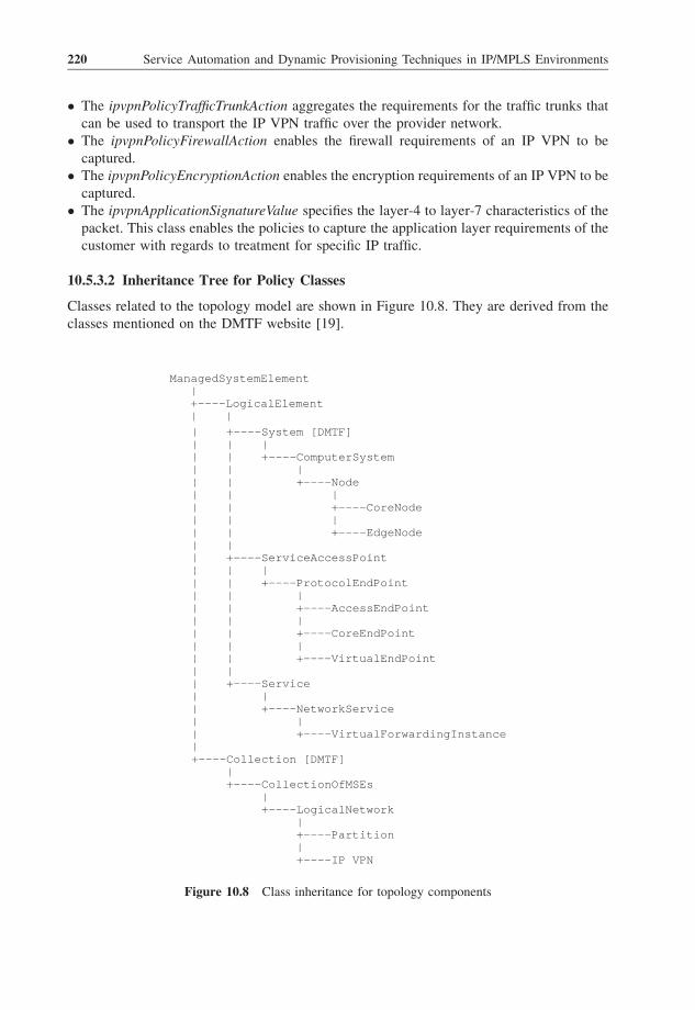
� The ipvpnPolicyTrafficTrunkAction aggregates the requirements for the traffic trunks that
can be used to transport the IP VPN traffic over the provider network.
� The ipvpnPolicyFirewallAction enables the firewall requirements of an IP VPN to be
captured.
� The ipvpnPolicyEncryptionAction enables the encryption requirements of an IP VPN to be
captured.
� The ipvpnApplicationSignatureValue specifies the layer-4 to layer-7 characteristics of the
packet. This class enables the policies to capture the application layer requirements of the
customer with regards to treatment for specific IP traffic.
10.5.3.2 Inheritance Tree for Policy Classes
Classes related to the topology model are shown in Figure 10.8. They are derived from the
classes mentioned on the DMTF website [19].
ManagedSystemElement | +----LogicalElement | | | +----System [DMTF] | | | | | +----ComputerSystem | | | | | +----Node | | | | | +----CoreNode | | | | | +----EdgeNode | | | +----ServiceAccessPoint | | | | | +----ProtocolEndPoint | | | | | +----AccessEndPoint | | | | | +----CoreEndPoint | | | | | +----VirtualEndPoint | | | +----Service | | | +----NetworkService | | | +----VirtualForwardingInstance | +----Collection [DMTF] | +----CollectionOfMSEs | +----LogicalNetwork | +----Partition | +----IP VPN
Figure 10.8 Class inheritance for topology components
220 Service Automation and Dynamic Provisioning Techniques in IP/MPLS Environments

The inheritance hierarchy (Figure 10.9) shows the various classes used to define relation-
ships between topology classes.
A detailed description of the IP VPN-specific classes that have been introduced in Section
10.5 can be found in Appendix 5.
10.6 Dynamic Production of IP VPN Services
The physical topology reflects the physical layout of the devices and their interfaces. They
are referenced by the policy action classes defined in the IP VPN information model. The
role of the policy server in the policy management framework is detailed in RFC 2753 [8].
The policy servers use this information to generate the configuration information that will be
processed by the IP VPN participating devices.
The topology of an IP VPN is an implicit result of the (device) configuration information,
i.e. the topology is displayed/described once the devices have been configured accordingly,
[unrooted] | +----Dependency | | | +----Link | | | | | +----VirtualLink | | | | | +----CoreLink | | | | | +----AccessLink | | | +----NodeInPartition | | | | | +----EdgeNodeInPartition | | | | | +----CoreNodeInPartition | | | +----AccessEndPointInVFI | | | +----VirtualEndPointInVFI | +----Component [DMTF] | +----ProtocolEndPointInNode | | | +----AccessEndPointInEdgeNode | | | +----CoreEndPointInEdgeNode | | | +----CoreEndPointInCoreNode | | | +----VirtualEndPointInEdgeNode | +----VFIInEdgeNode | +----EdgeNodeInIPVPN
Figure 10.9 Association inheritance for topology components
Automated Production of BGP/MPLS-based VPN Networks 221

in terms of architecture, QoS, security and management, as per a ‘global’ IP VPN
deployment policy.
The network devices involved in the forwarding of the IP VPN traffic as well as the virtual
links generated by the configuration represent the IP VPN topology.
10.7 Context of a Multidomain Environment
10.7.1 A Bit of Terminology
Some of the terminology used in this chapter is taken from RFC 4026 [20] and RFC 4031
[21]. ‘VPN’ in the context of this document refers specifically to BGP/MPLS-based VPN
services. In order to clarify the requirements listed in this document, it is necessary further to
define and introduce new terminology specific to multiprovider VPN services.
10.7.1.1 Agent
For the purposes of this chapter, an agent is a VPN service provider (VSP) who is
responsible for the management of multiparty business processes, negotiations and fulfill-
ment that allow the multiprovider VPN to function. The agent manages this responsibility by
either operationally complying with or coordinating policies across all parties involved in
delivering their customer’s end-to-end service. Policy compliance or multiparty policy
coordination is achieved either in a distributed or in a centralized manner:
� For distributed policy enforcement, cooperating VSPs agree upon the enforcement of
consistent policies for VPN service provisioning purposes. In this case, end-to-end policy
enforcement is distributed across multiple VSPs, each of which is a stakeholder in the
supply and enforcement of a fixed set of policies within the shared multi-AS environment.
AVPN customer defines its VPN service requirements with an agent who then maps these
requirements to the set of policies that may have been predefined by the VSP, and possibly
negotiated with the customer, then adapted to the customer’s specific requirements.
� For centralized policy enforcement, the agent coordinates, per customer, a set of policies
related to the management of the customer’s VPN service. In contrast to a shared multi-
AS environment, where policy enforcement is distributed across multiple VSPs, this agent
will coordinate policies and integrate VPN services per customer, thereby creating a
customer-specific environment that is dedicated to the agent’s customers only. The agent
may independently agree and manage service level specification (SLS) with each partner
VSP and offer an aggregated end-to-end SLS to their customer’s.
10.7.1.2 Multidomain Environment (MDE)
Two or more autonomous systems that may or may not be owned by separate administrative
authorities, and which are used to interconnect service endpoints (sites) of one or more VPNs.
10.7.1.3 VPN Peering Location (VPL)
A VPL is a physical location where VPN services delivered by one or more VSPs are
interconnected. Examples of VPLs include VSP central offices, a collocation facility or any
222 Service Automation and Dynamic Provisioning Techniques in IP/MPLS Environments

building common to one or more VSPs. A VPL could be operated by a single VSP, a
consortium of VSPs or a neutral third party.
10.7.1.4 VPN Service Provider (VSP)
A VSP is an operator who participates in the delivery of a single domain or multidomain
(MDE-wide) VPN service. In delivering the VPN service, the VSP may own a subset or all
of the participating network elements. Examples of VSPs include network service providers
(NSPs), systems integrators (SIs), network integrator (NIs), mobile operators (MOs) and
virtual network operators (VNOs).
10.7.2 Reference Model
Figure 10.10 shows a generic reference model for a multidomain environment. It shows the
relationships that exist between the various parties involved in the establishment of VPN
services that span multiple VSP-administered networks.
The MDE consists of sites interconnected via ASs. ASs are then interconnected via VPLs,
within the context of delivering VPN service offerings. There is potentially a one-to-many
relationship between VSPs and ASs, similarly there is potentially a one-to-many relationship
between VPL operators and VPLs. Note that VSPs may be remotely interconnected, that is,
VSPs do not necessarily need to be directly connected to each other through a given VPL.
With reference to Figure 10.10, the following sections detail examples of the coordination
of the various parties in the enforcement of a set of policies. These policies relate to the
provisioning of an MDE-wide VPN service and include (but are not limited to) addressing,
routing, QoS and security.
Agent
VSP 1 VPL 1 VSP 2
Customer
Site 1 Site 2
AS #1 AS #2
Figure 10.10 The MDE reference model
Automated Production of BGP/MPLS-based VPN Networks 223
10.7.2.1 Distributed Policy Enforcement Scheme
The customer’s agent is a single VSP (VSP1 in this example). VSP1 manages the relation-
ship with the customer, which includes the specification, instantiation, possible negotiation
and invocation of the customer’s SLS.
Cooperating VSPs, VSP1 and VSP2, have preagreed an enforced set of policies, including
the management of VPL1. The customer’s requirements are mapped by VSP1 to the
preagreed policies of VSP1 and VSP2.
10.7.2.2 Centralized Policy Enforcement Scheme
The customer’s agent is a systems integrator (SI). The SI does not own the network
infrastructure (the VPN networking elements), but manages the VPLs, as well as the
processes involved in connecting the VPLs with each relevant VSP-owned AS.
VSP1 and VSP2 independently provide customer-specific VPN services and associated
SLS instantiated templates to the SI who is then responsible for integrating each VSP’s VPN
service components and negotiating/invoking an end-to-end SLS with/for their customer.
10.8 Possible Extensions of the VPN Model
The IP VPN policy information model describes the IP VPN basic features – namely
connectivity, security and QoS. The IP VPN policy information model can be extended to
support new requirements generated as a result of new functions for the deployment of
value-added IP VPN services, like the integration of IP multicast transmission schemes
within the IP VPN.
References
[1] Goderis, D., T’Joens, Y., Jacquenet, C., Memenios, G., Pavlou, G., Egan, R., Griffin, D.,
Georgatsos, P. and Georgiadis L., ‘Attributes of a Service Level Specification (SLS) Template’,
draft-tequila-sls-03.txt, Work in Progress, October 2003.
[2] Mahdavi, J. and Paxson, V., ‘IPPM Metrics for Measuring Connectivity’, RFC 2678, September
1999.
[3] Muthukrishnan, K. and Malis, A., ‘A Core MPLS IP VPN Architecture’, RFC 2917, September
2000.
[4] Rosen, E. and Rekhter, Y., ‘BGP/MPLS IP Virtual Private Networks (VPNs)’, RFC 4364, February
2006.
[5] Rekhter, Y. et al., ‘Application of the Border Gateway Protocol in the Internet’, RFC 1772, March
1995.
[6] Gleeson, B. et al., ‘A Framework for IP Based Virtual Private Networks’, RFC 2764, February
2000.
[7] Moore, B. et al., ‘Policy Core Information Model – Version 1 Specification’, RFC 3060, February
2001.
[8] Yavatkar, R. et al., ‘A Framework for Policy-based Admission Control’, RFC 2753, January 2000.
[9] Zeilenga, K. et al., ‘Lightweight Directory Access Protocol (LDAP): Technical Specification Road
Map’, RFC 4510, June 2006.
[10] Strassner, J. et al., ‘Policy Core LDAP Schema’, RFC 3703, February 2004.
224 Service Automation and Dynamic Provisioning Techniques in IP/MPLS Environments

[11] Snir, Y. et al., ‘Policy Quality of Service (QoS) Information Model’, RFC 3644, November 2003.
[12] Blake, S. et al., ‘An Architecture for Differentiated Services’, RFC 2475, December 1998.
[13] Kent, S. and Atkinson, R. ‘Security Architecture for the Internet Protocol’, RFC 2401, November
1998.
[14] Kent, S. and Seo, K., ‘Security Architecture for the Internet Protocol’, RFC 4301, December 2005.
[15] Rosen, E. et al., ‘Multiprotocol Label Switching Architecture’, RFC 3031, January 2001.
[16] Moore, B. et al., ‘Policy Core Information Model Extensions’, RFC 3460, January 2003.
[17] Fang, L. et al., ‘Security Framework for Provider-Provisioned Virtual Private Networks
(PPVPNs)’, RFC 4111, July 2005.
[18] Srisuresh, P. and Holdredge, M., ‘IP Network Address Translator (NAT) Terminology and
Considerations’, RFC 2663, August 1999.
[19] Distributed Management Task Force, Inc., ‘DMTF Technologies: CIM Standards CIM Schema:
Version 2.5’, available via links on the following DMTF web page: http://www.dmtf.org/spec/
cim_schema_v25.html.
[20] Andersson, L. and Madsen, T., ‘Provider-Provisioned Virtual Private Network (VPN) Terminol-
ogy’, RFC 4026, March 2005.
[21] Carugi, M. et al., ‘Service Requirements for Layer 3 Provider Provisioned Virtual Private
Networks (PPVPNs)’, RFC 4031, April 2005.
Automated Production of BGP/MPLS-based VPN Networks 225


11
Dynamic Enforcementof Security Policiesin IP/MPLS Environments
Enforcing security policies in an IP/MPLS network usually involves the AAA chain.
However, it is worthwhile describing a little bit further what we define here as a security
policy. The most basic definition of a security policy is to define the ability of an end-user to
get IP connectivity from the network. This binary approach can be extended to the notion of
network resource; for instance, granting or not granting access to a VPN, to the Internet or to
multicast flows. In this section, we will focus on security policies attached to this definition,
even though network resources can take much more sophisticated aspects.
Through two different application examples extracted from real network architecture
scenarios, this section intends to provide the reader with an overview of various ways
dynamically to enforce security policies in networks:
� Wi-Fi access control through a web-based captive portal;
� company network access control using 802.1X.
11.1 Enforcing Security Policies for Web-based Access Control
Web-based access control is something often used for Wi-Fi access or line access in nomadic
situations (hotels, for instance). The scenario is simple: the end-user connects his/her
terminal to a public wire or activates his/her Wi-Fi connection. Putting aside the layer-2
connectivity (especially for Wi-Fi access), the terminal gets an IP address through a public
DHCP server. After opening his/her browser, the user requests an URL that is automatically
redirected to a captive portal, asking for a login and password, or another credential (room
number for billing in hotels, magic number printed on scratch cards, etc.). If the security test
Service Automation and Dynamic Provisioning Techniques in IP/MPLS Environments C. Jacquenet,
G. Bourdon and M. Boucadair
# 2008 John Wiley & Sons Ltd

is passed, the user can access the network service (Internet access, VPN, etc.), depending on
his/her authorization profile.
A lot of solutions exist in the market to put in place such scenarios. From very simple
solutions that are free to be used by individuals or SMEs who are interested in offering a
prepaid Internet access (like Chillispot) to the most complex and scalable solutions sized for
operators or major players with a consequent customer base [like Cisco subscriber access
and management (SAM)]. In this example, we will focus on the industrial solution proposed
by Cisco – the SAM.
The SAM is actually a package of two elements, the SSG service selection gateway (SSG)
and the subscriber edge services manager (SESM):
� The SSG is the gateway through which all IP traffic from and to the subscriber has to go.
This equipment is dedicated to subscriber connection aggregation, and to enforcement of
policies. The SSG will redirect user’s traffic to the SESM as long as the requested service
is not authorized and activated. The SSG is in charge of enforcing policies according to
the subscriber and service profiles managed by the AAA server and the SESM. It acts as
proxy-RADIUS for all authentication/authorization messages exchanged between the
AAA server and the SESM. The SSG is typically an edge router from the Cisco 7200,
7400 or 7600 series, for instance, at least running IOS 12.2(2)B.
� The SESM is the portal with which the subscriber interacts for authentication and service
selection. Actually, the SESM is not only an HTTP server capable of interacting with the
SSG, it is also a set of applications that are able to manage customer and service profiles,
depending on the degree of complexity in which it is used. The SESM communicates with
the SSG and the AAA server with the RADIUS protocol. For simplicity, here we will
consider the SESM in a simple configuration. The SESM can be hosted in a single
machine running Linux, Windows or Solaris.
Figure 11.1 shows how SESM and SSG are integrated in a web-based access control
architecture for Wi-Fi.
The SESM and the SSG use RADIUS to communicate to the AAA server. This AAA
server holds user profiles and service profiles: user profiles contain basic elements (login,
password, etc.) but also the list of services allowed for this user. The service profile is a
description of the services, with the technical parameters that are required to achieve each
service. The services can be grouped into ‘service groups’, to ease service management for
user subscriptions to bundles of services: a user profile can mention a set of service groups.
Firstly, here is the sequence of events occurring between the subscriber and the network in
order to get the service:
1. The subscriber turns on his/her terminal and activates Wi-Fi.
2. The user’s terminal attaches itself to the access point.
3. The user’s terminal requests an IP address through DHCP.
4. The user opens his/her web browser, and the traffic is redirected to the SESM at the first
URL request.
5. The browser displays the captive portal HTTPS page pushed by the SESM, requiring a
login and a password to connect.
228 Service Automation and Dynamic Provisioning Techniques in IP/MPLS Environments

6. The user enters his/her login and password through HTTPS.
7. The browser displays an SESM page with the services available for the user to select.
8. The user selects the service on this page.
9. The browser displays an SESM page indicating that the service is active.
10. The user can now use the network service.
From this simple event sequence, multiple actions and messages are exchanged between
the terminal, the SESM, the SSG and the AAA server. We consider here that layer-2
association as well as DHCP sequence has already occurred.
Two authorization phases are performed before the user can use his/her service:
� The user authentication and authorization phase, where the network authenticates the user
and identifies the services to which he/she has subscribed.
� The service activation and authorization phase, where the user selects the services s/he
wants to use, and where the network authorizes the selected service and enforces the
associated policies.
The user authentication phase corresponds to steps 4 to 6 in the event user sequence
listed above. The RADIUS messages that are exchanged in this scenario are shown in
Figure 11.2:
� Phase a (layer-2 attachment and DHCP exchanges are already done). The user sends a
request to the network to reach a URL through HTTP. The request is intercepted by the
SSG, which has a default policy rule to redirect HTTP traffic to the SESM when the IP
address is not authorized for available services. The HTTP request is redirected to the
Figure 11.1 SSG and SESM in a web-based access control architecture for Wi-Fi
Dynamic Enforcement of Security Policies in IP/MPLS Environments 229
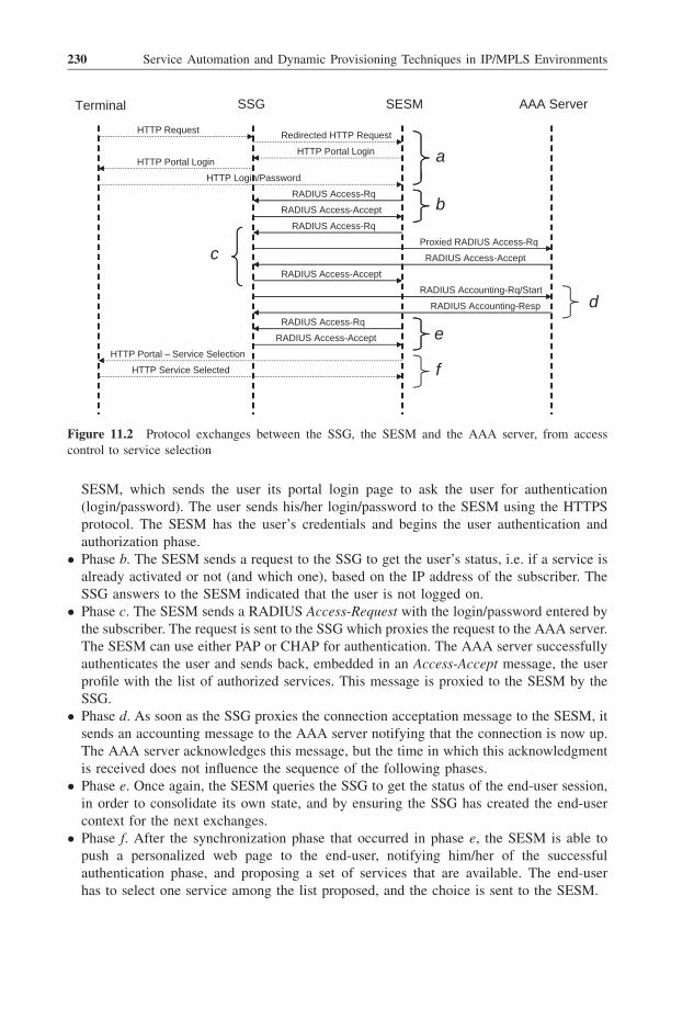
SESM, which sends the user its portal login page to ask the user for authentication
(login/password). The user sends his/her login/password to the SESM using the HTTPS
protocol. The SESM has the user’s credentials and begins the user authentication and
authorization phase.
� Phase b. The SESM sends a request to the SSG to get the user’s status, i.e. if a service is
already activated or not (and which one), based on the IP address of the subscriber. The
SSG answers to the SESM indicated that the user is not logged on.
� Phase c. The SESM sends a RADIUS Access-Request with the login/password entered by
the subscriber. The request is sent to the SSG which proxies the request to the AAA server.
The SESM can use either PAP or CHAP for authentication. The AAA server successfully
authenticates the user and sends back, embedded in an Access-Accept message, the user
profile with the list of authorized services. This message is proxied to the SESM by the
SSG.
� Phase d. As soon as the SSG proxies the connection acceptation message to the SESM, it
sends an accounting message to the AAA server notifying that the connection is now up.
The AAA server acknowledges this message, but the time in which this acknowledgment
is received does not influence the sequence of the following phases.
� Phase e. Once again, the SESM queries the SSG to get the status of the end-user session,
in order to consolidate its own state, and by ensuring the SSG has created the end-user
context for the next exchanges.
� Phase f. After the synchronization phase that occurred in phase e, the SESM is able to
push a personalized web page to the end-user, notifying him/her of the successful
authentication phase, and proposing a set of services that are available. The end-user
has to select one service among the list proposed, and the choice is sent to the SESM.
Terminal AAA ServerSESMSSG
RequestHTTP Redirected HTTP Request
HTTP Portal LoginHTTP Portal Login
HTTP Login/Password
RADIUS Access-Rq
a
RADIUS Access-Accept
Proxied RADIUS Access-Rq
RADIUS Access-Rq
RADIUS Access-Accept
Access-Accept
b
cRADIUS
RADIUS Accounting-Rq/Start
RADIUS Accounting-Resp
RADIUS Access-Rq
RADIUS Access-Accept
d
eHTTP Portal – Service Selection
HTTP Service Selected f
Figure 11.2 Protocol exchanges between the SSG, the SESM and the AAA server, from access
control to service selection
230 Service Automation and Dynamic Provisioning Techniques in IP/MPLS Environments

Then comes the service authorization phase, which really enforces service policies into
the SSG. The protocol sequence that follows is shown in Figure 11.3, corresponding to steps
6 to 10 in the event user sequence listed above:
� Phase g. Once the service has been selected by the end-user, the SESM queries the AAA
server to get service details. This is the only case where the SESM is in direct contact with
the AAA server without being proxied by the SSG. This phase is optional since the service
description can still be in SESM memory from the previous choice of another user.
� Phase h. Following answers and possibly following guidelines imposed by locally defined
policies, the SESM requests from the AAA server the authorization for the end-user to get
the selected service. The AAA requests are exchanged through the SSG. The service
description embedded in the reply message (Access-Accept) is then used by the SSG to
enforce the policy to be applied on the user’s traffic.
� Phase i. After receipt of the Access-Accept message from the AAA server (through the
SSG), the SESM queries the SSG to make sure the policy is enforced and the service is
available for the end-user. The SSG answers with a ‘logged on’ message including the
active service applied.
� Phase j. The SSG starts the accounting for the service as soon as it is activated. The
Accounting-Request message Start is thus sent to the AAA server which acknowledges it.
� Phase k. The SESM pushes a web page to the end-user, indicating that the selected service
is now available to be used. The traffic sent and received by the end-user goes through the
SSG as long as the policies are enforced in the SSG.
The way Cisco uses RADIUS in this example is quite interesting. The AAA protocol
is not just used to convey authentication data, accounting data and service policies to
Terminal AAA ServerSESMSSG
HTTP Portal – Service Selection
HTTP Service Selected
RADIUS Access-Accept
RADIUS Access-Rq
RADIUS Access-Rq
f
g
Proxied RADIUS Access-Rq
RADIUS Access-Accept
RADIUS Access-Accept
RADIUS Access-Rq
Access-Accept
h
RADIUS Accounting-Resp
RADIUS Accounting-Rq/Start
RADIUSi
jService ActivationHTTP Portal –
Service traffick
Figure 11.3 Protocol exchanges between the SSG, the SESM and the AAA server for service
selection to policy enforcement
Dynamic Enforcement of Security Policies in IP/MPLS Environments 231

enforce on the SSG. RADIUS is also used here between the SESM and the SSG as a
query/response protocol to get the status of the end-user. In steps b, e and i, the SESM
queries the SSG to get the status of the end-user, in order to synchronize HTTP pages to
be presented to him/her. This is a very specific way of using this protocol, and Cisco uses
specific AVPs with proprietary codes for this purpose. These queries are considered as
part of the whole solution, and no compatibility with other vendors is required, nor
compatibility between operators since the SESM and SSG are managed by the same
administrative entity.
Note that two accounting exchanges take place for service activation. Firstly, there is a
connection accounting that is triggered as soon as the subscriber is authenticated.
Secondly, a service accounting is activated as soon as the service is enforced in the
SSG. The SSG is in charge of sending accounting information to the AAA server
because the SSG is aware of service usage (traffic exchanged), not the SESM.
Once the subscriber wants to end his/her session, s/he has to notify the SESM that s/he
wants to log out; otherwise, the service will still be active. There are two possible ways to
avoid keeping a service session up while the terminal is no longer connected: either
configuring a maximum session timeout after which the subscriber is forced to reconnect to
the service through SESM, or a maximum idle timeout specifying the maximum delay of
inactivity after which the subscriber is automatically logged out by the system. These
parameters are sent with the user profile during phase c. This mechanism is particularly
useful for this case where there is no notion of session, apart from the DHCP lease time
allowed during connection establishment to the network. In the case of network failure, this
helps to free unused resources, but it is also helpful if the service is billed on the basis of the
time spent, either prepaid or post-paid. In our example shown in Figure 11.4, we consider
that the subscriber manually logs out from the service by hitting a disconnect button
available on the SESM portal web page
Terminal AAA ServerSESMSSG
trafficService
Log OffHTTP Portal – l
RADIUS Access-AcceptmRADIUS Access-Rq
RADIUS Access-AcceptnRADIUS Access-Rq
RADIUS Accounting-Rq/Start
RADIUS Accounting-Resp o
RADIUS Accounting-Resp
RADIUS Accounting-Rq/Start
pRADIUS Access-Rq
RADIUS Access-Acceptq
Figure 11.4 Protocol exchanges between the SSG, the SESM and the AAA server when the service is
stopped
232 Service Automation and Dynamic Provisioning Techniques in IP/MPLS Environments

� Phase l. The subscriber goes to the SESM web page portal to log out. Logging out also
means that the service activated in the context of his/her connection will be terminated.
� Phase m. The SESM queries the SSG to get information about the user’s session. The SSG
replies back by indicating that the user is connected to the system, with a mention of the
service activated.
� Phase n. The SESM sends a request to disconnect the subscriber from the SSG. It is
interesting to note that this request uses Access-Request/Access-Accept messages
instead of Disconnect-Request/Disconnect-Response messages defined in RFC 3576
(see Chapter 3) for this purpose. Once again, this choice is due to multiple factors:
SESM/SSG is a Cisco proprietary solution without any requirement to interoperate, and
the IETF standard was not yet ready when the system was conceived.
� Phase o. The SSG stops the connection of the subscriber, and restores the default policies
for the subscriber’s IP address. The SSG first notifies the AAA server that the service
activated for this user is terminated.
� Phase p. The SSG then sends the accounting message notifying the AAA server that
the connection is terminated for this user. We must understand here that ‘connection’
refers to the relationship maintained between the terminal and the SESM. It must not
be understood as the connectivity that is established with the access nodes (APs): at
this stage, the subscriber still has his/her Wi-Fi connectivity as well as his/her IP
address.
� Phase q. The SESM queries the SSG to consolidate the states on both pieces of equipment,
to make sure that the context pertaining to the subscriber has been released on the SSG as
well.
Once these steps are over, the default security policy is enforced back for the subscriber IP
address, meaning that all HTTP traffic issued by the subscriber will be redirected to the
SESM.
To enforce policies on the SSG, it is interesting to focus on some of the attributes sent
by the AAA server when transmitting the user profile in step c as well as the service
profile in steps g and h. Along with standard attributes that are used for traditional
authentication, five Cisco-specific sub-AVPs are used, which, for some of them, are split
into subactions:
� Cisco-AVPair (AVP 26, vendor ID 9, subattribute ID 1). This AVP is used to convey
general parameters that are used in different Cisco solutions. Cisco defined its own syntax
to discriminate between the different actions. The most interesting parameters are the
access control lists (ACLs), downstream or upstream, that can be associated with the
subscriber. It is possible to use this sub-AVP to define ACLs related to a user profile (if
there is a specific policy for this user), or related to a service profile (when all subscribers
attached to a service must have the same set of ACLs applied).
� Cisco-SSG-Account-Info (AVP 26, vendor ID 9, subattribute ID 250). This AVP can
be used for five different usages specifically dedicated to describe the user profile or
the service group profile. We will focus a little bit more on this AVP later.
� Cisco-SSG-Service-Info (AVP 26, vendor ID 9, subattribute ID 251). This AVP can be
used for 14 different usages specifically dedicated to describe the service. This does
not mean that the service will only be described by this AVP, however.
Dynamic Enforcement of Security Policies in IP/MPLS Environments 233

� Cisco-SSG-Command-Code (AVP 26, vendor ID 9, subattribute ID 252). This AVP is
used for specific exchanges between the SESM and SSG for specific queries and actions
(user status, subscriber log out).
� Cisco-SSG-Control-Info (AVP 26, vendor ID 9, subattribute ID 253). This AVP is used
to help in designating and defining next hop entries.
Taking as an example of how the SSG is able to create a user context by interpreting
RADIUS attributes sent by the AAA server, we will focus on the Cisco-SSG-Account-Info
attribute used to define the user’s profile. Five meanings are possible for this AVP by
following a specific syntax of the type: <command>value. The <command> is a letterthat gives the meaning of the attribute:
� A for Auto Service indicates the service name the SSG has to enforce by default.
� I for Service Group Description gives a description of a service group in plain text, to be
displayed to the subscriber by the SESM, for instance.
� H or U indicates the default URL to which the subscriber wishes to be connected.
� G for Service Group indicates the name of a service group that is attached to the
subscriber.
� N indicates a Service Name that is attached to the subscriber.
Let’s take the example of the profile of user 1, who is eligible to Internet access and to the
Company’s VPN access (ACME). If we consider that user 1 wants to be connected by
default (without service selection phase) to the Internet, the user’s profile held in the AAA
server (Free RADIUS format) will look like this:
User1 Password ¼ ‘‘userpwd’’,Session-Timeout ¼ 3600,
Account-Info ¼ ‘‘Ninternet’’,Account-Info ¼ ‘‘Nacme-vpn’’,Account-Info ¼ ‘‘Ainternet’’
In the same manner, the services ‘internet’ and ‘acme-vpn’ will be described by using
attributes embedded in Cisco-SSG-Service-Info, following a close syntax but with other
possible actions.
In conclusion, it is important to mention that this kind of architecture for a Wi-Fi
access has some drawbacks, especially in terms of security. Firstly, the communications
are not encrypted by this system. This means that the user will have to activate a specific
VPN client on his/her terminal if s/he wants to secure his/her traffic to a specific
endpoint (such as a company’s VPN gateway). Everyone within the 802.11 radio range
will be able to inspect the user’s traffic. The second security drawback of this solution is
the risk of the connectivity being stolen by a malicious user: it is still possible to ‘kick
out’ a terminal from its Wi-Fi connection and to take its place by spoofing its MAC
address. It is important to note that, at this time, 802.11i [1], Wi-Fi protected access
(WPA) or WPA2 remains the most secure way to connect to a wireless access point.
However, these technologies are not user friendly (it is often necessary to install
certificates on the terminal and to set up complex security infrastructures), which
234 Service Automation and Dynamic Provisioning Techniques in IP/MPLS Environments

explains why web-based security access is so popular nowadays. The bottom line is
always to keep in mind the degree of security required considering the usage of the
network infrastructure by the end-users. For a wireless ISP it is clear that security
considerations have to be taken into account, not from a subscriber perspective, but from
a business perspective, by protecting itself from attacks and service theft. For a company
that wants to provide access to its VPN through Wi-Fi, the security requirements are
much greater and must take into account user integrity as well. The example provided
here is definitely not suitable in this case.
11.2 Enforcing Security Policies in Companies with 802.1X
One usual drawback encountered by companies is to secure their LAN access. In order to do
this, IEEE 802.1X has been defined to secure the LAN by only allowing terminals that are
able to present known and verifiable credentials to the network. In the context of IP/MPLS
networks, one might wonder why 802.1X, exclusively defined for layer-2 connectivity, is
helpful. Actually, several items of layer-2 equipment available on the market are also
capable of layer-3/4 treatments, so it is just moving one step forward to take the opportunity
to use the AAA exchanges performed during the 802.1X authentication phase to convey
additional policies to be enforced at the IP level. Of course, this is not the way the IEEE
standardized access control, but it is an efficient way to enforce customized policies
transparently for the end-user.
To illustrate this, we will take the example of the ACME company which wants to offer
two levels of security in its internal network: the first security level is accessible to everyone
who is employed by the company, whereas the second level is reserved for the high
management of the company who have access to sensitive applications and databases (see
Figure 11.5). The advantage of treating the security aspect on the IP level rather than the
layer-2 level is to dissociate the right to access to resources from the VLAN aspect (not
always possible when the company has multiple sites interconnected through an L3 VPN).
It is also possible to apply security rules in equipment placed on the path used to access the
servers needing protection, based on the IP address of the terminal requesting access. In the
latter case, the solution would consist in assigning a specific IP address to terminals that are
allowed to access resources, by placing firewall rules to stop packets coming from non-
authorized IP addresses. This way to proceed can become burdensome, as it requires
managing several pools of addresses, with the risk of a security breach when the access lists
and the IP pools are not consistent. Moreover, the process of address assignment, usually
performed through DHCP, relies on the MAC address: this address can easily be forged;
DHCP user databases have to be refreshed as soon as a user changes his/her terminal
hardware. Finally, this method relies on the assumption that MAC addresses are unique
worldwide, which has long been proven to be false because of the casual process followed
by some Ethernet card vendors.
The solution proposed here makes use of the filtering capabilities of L2/L3 switches in
order to block IP packets generated by terminals that are not allowed access to some parts of
the network. This way to proceed is the most efficient way to enforce network IP security
policies directly bound to the credentials presented by the terminal. It is not linked to the
hardware of the terminal, it is not linked to the port to which the terminal is connected and it
Dynamic Enforcement of Security Policies in IP/MPLS Environments 235

is not linked to the IP address obtained by the terminal from the DHCP server. The elements
of the solution are as follows:
� terminals embedding an 802.1X module, with address assignment either done dynami-
cally through DHCP or statically configured;
� an L2/L3 switch connected to the company’s network backbone, activating the 802.1X
authenticator role with remote authentication through RADIUS;
� an AAA server that stores the individual security policy to be enforced, running RADIUS
and EAP methods enforced by the company.
The choice of the L2/L3 switch brand can be crucial here: it is possible to use a vendor-
specific solution (which usually is the easiest way to proceed, even though it is a drawback
for network evolution), or to configure each switch in the network with the policy to be
enforced, the user profile making reference to this profile. It is a matter of fact that the latter
is not the preferred solution, as it requires reconfiguring all switches if there is a change in IP
address filters. Even with an automated update of managed equipment through SNMP MIBs,
the risk is higher than transferring IP policies dynamically from a centralized point.
In this example, we will make use of Cisco Catalyst 3550 equipment, which is capable
of assuming L2 connectivity, an 802.1X authenticator and an ACL for layer-3 filtering.
Figure 11.5 Network architecture for dynamic security enforcement
236 Service Automation and Dynamic Provisioning Techniques in IP/MPLS Environments

This equipment is also capable of applying individual filters using the two methods
mentioned above: either by using the RADIUS Filter-Id attribute (see Section 3.2.5), or
by using the vendor-specific AVP Cisco-AVPair attribute embedding the proper extended
access lists (either inbound or outbound), as used in the previous example (Section 11.1).
The general architecture of our company’s network is shown in Figure 11.5.
Figure 11.6 (applying the diagram presented in Section 3.2.1.2) shows the message
exchange that takes place between the terminal and the switch (using EAPoL, as
specified in 802.1X [2]), and between the switch and the AAA server holding the
security policy to be applied for this user. This user is considered as a regular employee
and therefore is not allowed to access subnet 10.0.1.0/24. The corresponding ACL can be
statically configured in the switch with the following command line:
Switch (config) # access-list 101 deny ip any any 10.0.1.0 0.0.0.255
The sequence of messages is detailed in Section 3.2.1.2. The Access-Accept message sent
by the RADIUS server in 8a to the switch embeds a specific AVP, the Cisco-AVPair, which
contains the filter to apply in order to block access to the 10.0.1.0/24 subnet, which is
reserved to managers. The following line has to be added to the user profile (formatting the
aforementioned ACL into the Cisco-AVPair attribute):
Cisco-AVPair ¼ ‘‘ip:inacl#101¼deny ip any any 10.0.1.0 0.0.0.255’’
Cisco Catalyst 3550(authenticator)
AAA Server(RADIUS Server)User Terminal
Steps 4 to 7 repeateduntil success or failure:
Access Granted,Transmission ofSecurity Policies
ACL enforcement
OK
Figure 11.6 EAP exchanges for dynamic provisioning of individual security policy
Dynamic Enforcement of Security Policies in IP/MPLS Environments 237

The example given here is suitable not only for wired Ethernet access but also when a
WLAN access is provided to access the company’s VPN. In such a situation, the
authentication phase is more complex and requires using 802.11i, WPA or WPA2 (Wi-Fi
protected access, adopted by the Wi-Fi Alliance and based on 802.1X work). Policy security
provisioning would be realized the same way as described here (conveyed in the RADIUS
Access-Accept message).
References
[1] IEEE 802.11i – Medium Access Control (MAC) Security Enhancements, Amendment 6 to IEEE
Standard for Information technology – Telecommunications and Information Exchange Between
Systems – Local and Metropolitan Area Networks – Specific Requirements – Part 11: Wireless
Medium Access Control (MAC) and Physical Layer (PHY) Specifications.
[2] IEEE Standard 802.1X-2001. IEEE Standard for Local and Metropolitan Area Networks – Port-
Based Network Access Control.
238 Service Automation and Dynamic Provisioning Techniques in IP/MPLS Environments

12
Future Challenges
12.1 Introduction
In today’s Internet, configuration procedures are achieved by technical personnel who are
required to have an ever-growing level of expertise because of the various technologies and
features that need to be used, configured and activated to deploy a wide range of IP service
offerings. This level of expertise has become mandatory as each equipment manufacturer has
developed its own interfaces and configuration schemes. In addition, as IP services may rely
upon the activation of a set of sophisticated yet complex features, the time needed to
adequately provision such services is also increasing.
As a consequence, the specification and the use of standardized protocol (for conveying
configuration information) and interfaces should dramatically help in facilitating, if not
automating, the configuration process and the operational production of a wide range of IP
services.
12.1.1 Current Issues with Configuration Procedures
This section aims to list issues that should be carefully studied when dealing with
configuration tasks. The items below should be taken into account when designing a
protocol for configuration purposes.
12.1.1.1 Protocol Diversity
The production of a whole set of IP yet complex services relies upon the activation of a set of
capabilities in the participating devices. In particular, a large set of protocols need to be
configured, such as routing protocols, management protocols and security protocols, not to
mention capabilities that relate to addressing scheme management, QoS policy enforcement,
etc.
Service Automation and Dynamic Provisioning Techniques in IP/MPLS Environments C. Jacquenet,
G. Bourdon and M. Boucadair
# 2008 John Wiley & Sons Ltd

Such a diversity of features and protocols may increase the risk of inconsistencies.
Therefore, the configuration information that is forwarded to the whole set of participating
devices for producing a given service or a set of services should be consistent, whatever the
number of features/services to be activated/deployed in the network.
12.1.1.2 Topology Discovery
Network operators should have means to dynamically discover the topology of their
network. This topology information should be as elaborate as possible, including details
like the links that connect network devices, including information about their capacity, such
as the total bandwidth, the available bandwidth, the bandwidth that can be reserved, etc.
12.1.1.3 Scalability
As far as scalability is concerned, adequate indicators should be specified in order to qualify
the ability of a given technical means to support a large number of configuration processes.
The maintenance of these processes should not impact on the performance of a given system
(a system is a set of elements that compose the key fundamentals of an architecture that aims
to deliver configuration data).
Therefore, configuration operations should be qualified with performance indicators in
order to check whether the architecture designed for configuration management is scalable in
terms of:
� the volume of configuration data to be processed per unit of time and according to the
number of capabilities and devices that need to be configured;
� the volume of information generated by any reporting mechanism that may be associated
with a configuration process;
� the number of processes that are created in order to achieve specific configuration
operations.
12.1.2 Towards Service-driven Configuration Policies
Current configuration practice basically focuses on elementary functions, i.e. configuration
management for a given service offering breaks down into a set of elementary tasks. Thus,
the consistency of configuration operations for producing IP services must be checked by
any means appropriate, while current configuration methods can, at best, only check if
provisioning decisions are correctly enforced by a single device.
A network device should be seen as a means to deploy a service and not just as a
component of such a service. Thus, service configuration and production techniques should
not focus on a set of devices taken one by one, but on the service itself, which will rely upon
a set of features that need to be configured and activated in various regions of the network
that supports that service.
Service providers could dedicate centralized entities that would be responsible for the
provisioning and the management of participating devices. The main function of these
centralized entities would be to make appropriate decisions and generate convenient
240 Service Automation and Dynamic Provisioning Techniques in IP/MPLS Environments

configuration data that would be delivered to the participating devices. In addition, these
centralized entities would make sure of the consistency of the decisions that are taken to
produce the service, as per a dynamic configuration policy enforcement scheme.
Service-oriented configuration should rely upon the following requirements:
� The data models must be service driven.
� The configuration protocol(s) should reuse existing data and information models.
� The configuration protocol(s) should be flexible enough for further enhancement and
addition of new functionalities that in the future could prove to be a must.
� The configuration protocol(s) should provide means to assess the consistency of the
configuration tasks and to check the validity (or correctness) of the configuration of the
service before its operation.
12.2 Towards the Standardization of Dynamic Service Subscriptionand Negotiation Techniques
The previous chapters of this book have discussed the various issues and solutions related to
automated deployment and operation of services over IP/MPLS network infrastructures by
means of dynamic policy enforcement techniques. In the past 2 years, investigation in the
field of dynamic service subscription and negotiation techniques has dramatically progressed
by forming a community of vendors and operators who have decided to initiate the
standardization of the architectural framework where such techniques would naturally
serve as a cornerstone.
Within a multiple-play service environment, this community, which has been named the
IPsphere Forum (IPSF) [1] is currently addressing the following very basic questions from a
standardization standpoint:
� What if customers had the ability to dynamically subscribe to a wide range of service
offerings and even negotiate the level of quality associated with such services?
� What if service providers had the ability to automate the service production process,
whether such a service can be deployed at the scale of the Internet or its access limited to
the provider’s own domain?
12.2.1 Basic Motivation
The IPSF aims to enhance the commercial framework for IP services to provide a win–
win scenario for all stakeholders, where buyers of network-facilitated services can enjoy
an expanding and evolving set of potential experiences, where sellers are able to offer an
increasingly richer array of valued services and where collaborating service providers
have a clear economic incentive for contributing their network, IT and associated
resources.
12.2.2 Commercial Framework
The IPsphere framework [2] specifies mechanisms by which the next generation of IP
services, and their associated market and revenue potential, can be realized. These
Future Challenges 241

mechanisms create a commercial framework by which resource improvements that add
value to service delivery (e.g. dynamic provisioning techniques, automated service produc-
tion procedures) can be offered.
The major high-level design goals of the IPsphere framework are as follows:
� First and foremost, all providers can present whatever contribution they care to make to a
service mix at whatever price they find compelling, allowing customers to select the best
deal overall.
� The investments of any provider in a service’s underlying infrastructure must be protected.
� Business relationships are able to be flexibly established via a loosely coupled, network-
technology-agnostic business layer, called the service structuring stratum (SSS) in the
IPSF reference model.
� Services can be composed from a provider’s own resource capabilities and – where
desired or required – from the offerings of other providers, assuming agreements between
such providers that can be contractually defined through the use of the aforementioned
SSS layer capabilities.
� Providers need only publish the service–business relationships that they are willing to
allow others to select from.
� Service publication can be tailored to give different views to various potential buyers/
partners.
Any conceivable business model can be tried, and so the best model is likely to be
available for selection over time, thereby creating an optimum market.
12.2.3 A Service-oriented Architecture
The IPsphere technical framework is based upon the service-oriented architecture (SOA)
composition model. As shown in Figure 12.1, this approach provides for the connection of
the functional units of an application, called ‘services’ (or ‘elements’ in the IPsphere
Figure 12.1 The IPSF model
242 Service Automation and Dynamic Provisioning Techniques in IP/MPLS Environments

vernacular), through well-defined interfaces [namely the customer-to-network Interface
(CNI), which to some degree can be compared with user-to-network interfaces (UNIs) in
other environments, and the intercarrier interface (ICI), which to some degree can be
compared with network-to-network Interfaces (NNIs) in other environments].
The generic identification of network management systems (NMSs) in Figure 12.1 reflects
the need for storing, maintaining and updating the various policies (routing, traffic
engineering, security, etc.) that will be derived from the SSS-based negotiations, and that
will be enforced by the network resources involved in the deployment and the management
of the IPSF-inferred services.
SOA also emphasizes loose coupling between services. Loose coupling precludes
undocumented interactions between services, for example through shared data, and it also
supports the independent evolution of interfaces and IPsphere elements.
SOA also has the advantage that an element’s interface is defined in a way that is
independent of the hardware platform, the operating system, the hosting middleware and the
programming language used to implement the element. This allows elements, built on a
variety of systems, to interact with each other in a uniform and universal manner. In addition,
the applications’ interfaces and elements are expressed using business terms and concepts –
they are not technology focused.
The benefit of a loosely coupled system is in its agility – the ability to accommodate
changes in the structure and implementation of the internals of an element. By contrast, tight
coupling means that the interfaces between the different components of an application are
dependent on the form of implementation, making the system brittle when changes are made
to components.
The agile nature of loosely coupled systems serves the need of a business to adapt rapidly
to changes in policies, the business environment, product offerings, partnerships and
regulatory requirements.
12.2.4 Publishing and Accessing Services
The IPsphere framework is made up of a federation of providers who share a service
structuring stratum connection for business coordination. The interconnected networks use
standard packet protocols for service signaling, but at key points in and between network
jurisdictions there are ‘IPsphere interface points’ where business relationship management
must be structured (Figure 12.2).
Figure 12.2 A pan-provider environment
Future Challenges 243

The policy and control stratum is to some degree equivalent to the control and manage-
ment planes in classical representations, while the traffic handling stratum can be easily
compared with the capabilities that are activated at the data plane.
A provider makes an explicit business decision to participate in a pan-provider
service, and that decision is communicated by publishing a list of ‘elements’ represent-
ing service offers the provider is willing to make and the commercial conditions under
which the offer is valid. These are combined with elements from other providers to
create services.
Figure 12.3 further elaborates on the role of the SSS layer in the service publication and
composition processes.
12.2.5 Example of Automated IP VPN Service Composition
12.2.5.1 VPN Service Subscription Phase
This is where the SSS layer steps in by:
� presenting the available services for the customer’s selection;
Figure 12.3 Role of the IPsphere’s service structuring stratum in the dynamic service publication and
composition processes
244 Service Automation and Dynamic Provisioning Techniques in IP/MPLS Environments

� providing receiver access control capabilities that will be solicited for receiver identifica-
tion and authentication purposes;
� providing means for electronic payment.
12.2.5.2 VPN Service Negotiation Phase
The delivery of pan-provider VPN services is conditioned by several contexts, which include
(but are not necessarily limited to):
� The access capabilities of each VPN site. These may possibly influence traffic encoding
schemes (yielding access-inferred adaptive capabilities that should be supported by the
source, based upon dynamic notification capabilities of the SSS or the PCS layers) as well
as the traffic forwarding policies (yielding DiffServ-based encoding schemes and dynamic
per-hop behavior (PHB) enforcement through the use of the PCS layer).
� The network conditions. These may yield the design and the enforcement of VPN-specific
traffic engineering policies, hence soliciting the PCS layer on the basis of the number of
instantiated service level specification templates being processed by the SSS layer in a
given period of time.
� Time considerations. The service to be accessed by the users might be available for a
limited period of time only (working hours, for example). From this standpoint, the
corresponding information should be explicitly described in the SLS to be processed by
the SSS layer, possibly yielding the activation of specific resource provisioning cycles
through the PCS layer.
12.2.5.3 VPN Service Operation
Once the subscription and negotiation phases are completed (including the completion of
the transactional payment procedure, if any), the VPN service must be delivered to the
customer. This means that all the relevant configuration information must have been
provided to all the devices that are involved in the provisioning of the service up to the
customer.
The corresponding configuration policy will be instantiated by means of PCS capabilities,
based upon the SLS-formatted information that has been processed by the SSS layer. And it
will be enforced by some policy enforcement point (PEP)-equivalent capabilities to be
embedded in the aforementioned participating devices, including the support of monitoring
capabilities that should help in assessing how efficient such a policy enforcement is, and how
compliant the service is, as far as the customer’s requirements (QoS, security, management,
etc.) are concerned.
12.2.5.4 VPN Communication Flows
Figure 12.4 depicts the communication flows between a customer and a VPN service
provider.
Future Challenges 245

12.3 Introducing Self-organizing Networks
12.3.1 What is a Self-organizing Network?
The deployment and the operation of a wide range of service offerings in highly volatile,
dynamic environments (such as wireless mesh networks) is the next challenge that service
providers will have to address. Such a challenge relates to the so-called ATAWAD (Any
Time, Any Where, Any Device) paradigm, which basically suggests that any kind of service
offering should be accessed whatever the access technology (fixed or mobile), whatever the
terminal device technology (cell phone, PC, TV set, etc.) and whether the customer is in
motion or not. In addition, access to the service may sometimes yield the establishment of
environment-constrained intermittent communications, hence questioning the level of
quality associated with the delivery of the service.
These environmental issues have encouraged investigation in the field of self-organizing
networks (SONs) [3], where self-organization means that a functional structure appears and
maintains itself spontaneously: a self-organized system is a system that evolves towards an
organized form autonomously. Self-organization can be found in physics, biology or
economics. As an example, a flock of seagulls will behave similarly at a collective level.
Point of
‘Service Consumption’
Point of
‘Service Egress’
Access /
Projection
Transport /
Connection
Access/
Projection
Point of
‘Service Ingress’
Out-of-Band Service Order (to customer’s own carrier)
Setup Start (FT SLS)
Setup Negotiate (optional) (SLS)
Setup Complete (SLS)
Activate Start (Network SLS)
Activate Negotiate (optional) (SLS)
Activate Complete (SLS, VPNID)
Setup
(Reservation)
Activate
(Execution)
In-Life Start (SLS/VPNID)
In-Life ALERT (VPNID, Event Code)
In-Life Complete (VPNID)
In-Life
(Assurance)
Point of
‘Service Creation’
Figure 12.4 Communication flows of VPN service composition and deployment
246 Service Automation and Dynamic Provisioning Techniques in IP/MPLS Environments

A self-organizing system can further be defined as a system that organizes itself by means
of local interactions. This implicitly assumes that such a system is organized without any
central control as far as the global behavior of the system is concerned. From this
perspective, a SON network is deployed with no preconfigured support for interconnecting
the SON devices.
SON networks are essentially highly dynamic: while ‘classical’ networks are
designed according to a network planning policy that will affect the importance of
the mesh and the dimensioning of both the transmission and the switching resources,
SON devices organize themselves into a network architecture and deal with the
networking processes (forwarding, routing) by themselves at runtime, intelligently
and autonomously.
In a SON network, traffic may very well modify the behavior of the SON devices: a
typical example is mobile ad hoc networks (MANETs) [4], where mobile devices (laptops,
cell phones, etc.) communicate with each other over a wireless infrastructure in a distributed
manner, so as to provide the relevant forwarding capabilities in the absence of a fixed
infrastructure. Therefore, the forwarding policy enforced by MANET routers will evolve
according to the motion of the users.
12.3.2 Characteristics of SON Networks and Devices
Generally speaking, networks consist of resources (processing, bandwidth and memory) and
constraints (power and latency). Although SON networks do require power and memory
(because of the support of autonomic capabilities), they optimize the resource/constraint
ratio; for example, active caching uses processing and memory to reduce bandwidth usage
and latency, yielding the deployment of cache servers in points of presence (POP) locations
that are as close to the users as possible.
SON nodes collect the information about the network state (congestion occurrences,
moving users, etc.) and will use this information better to address the following issues:
� dynamic location of contents, taking into account the location of the user as well as his/her
access conditions (whether the user is in motion or not, how the access rate can
dynamically influence the way the traffic will be encoded/delivered/engineered to the
user as per his/her request, how a user in motion may trigger a relocation process of the
information to be retrieved, etc.);
� dynamic publishing of a range of services that may be accessed by a user, based upon his/
her profile, and/or his/her location (at home, at work, in motion, etc.) and/or his/her
interests (e.g. dynamically informing the user about flight delays while he/she is
approaching the airport), etc.;
� dynamic (re)configuration of network devices, depending on the traffic load conditions,
the provisioning of additional content servers, etc.;
� dynamic notification of users about the efficiency of a quality of service (QoS) and/or
security policy, possibly based upon the dynamic activation of monitoring capabilities in
network devices that will facilitate the accounting and invoicing of the services subscribed
to by the user, etc.
Future Challenges 247

12.3.3 On Self-management
SON nodes manage and control themselves and can be operated in a stand-alone
fashion. Management actions can be coordinated for the sake of consistency, hence
not excluding a mix of centralized and distributed management architectures, as
depicted in Figure 12.5.
12.3.4 SON Algorithms and How to Use Them for EnhancingDynamic Policy Enforcement Schemes
SON nodes organize themselves according to four phases:
� Discovery. Each SON node identifies its set of neighbors and defines the radius of data
transmission so as to cope with scalability constraints.
� Organization. Each SON node computes, maintains and distributes its forwarding table
according to the information exchanged during the discovery phase. Once this phase is
completed, the network is said to be organized.
� Maintenance. SON nodes notify their neighbors about their presence, and about any
change in the topology that may have affected their own forwarding decision process.
SON nodes update their forwarding tables accordingly, including the connectivity graph
which is derived from such tables.
� Reorganization. Whenever an event affects the information maintained by the SON nodes
(link/node failures, for example).
Figure 12.5 SON management architectures
248 Service Automation and Dynamic Provisioning Techniques in IP/MPLS Environments

Such advanced capabilities could be used for dynamic policy enforcement purposes in
highly volatile, dynamic environments, where the quality of services is likely to be degraded
because of the constraints of such environments (like still receiving a TV content with no
perception of degraded quality when jumping on a bus that enters a tunnel).
In that case, SON techniques would be part of the policy enforcement design scheme,
where:
� Local rules that achieve global properties are enforced, e.g. ‘access-aware’ multicast-
enabled SON nodes to forward IPTV traffic with the required level of quality;
� implicit coordination is exploited, e.g. hello mechanisms are used for maintaining
connectivity graph information beyond SON node discovery;
� long-lived state information is minimized, e.g. to accommodate zapping behaviors of
IPTV customers (in motion);
� dynamically adaptive protocols are preferred, e.g. to notify cluster nodes about any
topology change and enforce (updated) forwarding policies accordingly.
12.3.5 SON-inferred Business Opportunities
SON techniques are often seen as key drivers for addressing the aforementioned ATAWAD
paradigm. Context-aware SON techniques can be seen as a means to develop business, e.g.
by employing user location information as an advanced routing metric to accelerate the
development and the production of user-centric services, such as interactive TV. The
automated production of complex, QoS-demanding services in highly dynamic environ-
ments can also be facilitated by SON capabilities.
References
[1] http://www.ipsphereforum.org
[2] Alateras, J. et al., ‘IPsphere Framework Technical Specification (Release 1)’, June 2007.
[3] Nakano, T. and Suda, T., ‘Self-organizing Network Services with Evolutionary Adaptation’, IEEE
Transactions on Neural Networks, 16(5), September 2005, 1269–1278,
[4] Hoebeke, H. et al., ‘An Overview of Mobile Ad-Hoc Networks: Applications and Challenges’,
Proceedings of the 43rd European Telecommunication Congress, Ghent, Belgium, November
2004, pp. 60–66.
Future Challenges 249


Appendices


APPENDIX 1
XML schema for NETCONFRPCs and Operations
<?xml version¼‘‘1.0’’ encoding¼‘‘UTF-8’’?><xs:schema xmlns:xs¼‘‘http://www.w3.org/2001/XMLSchema’’
xmlns¼‘‘urn:ietf:params:xml:ns:netconf:base:1.0’’targetNamespace¼‘‘urn:ietf:params:xml:ns:netconf:base:1.0’’elementFormDefault¼‘‘qualified’’attributeFormDefault¼‘‘unqualified’’xml:lang¼‘‘en’’>
<!- -import standard XML definitions
- ->
<xs:import namespace¼‘‘http://www.w3.org/XML/1998/namespace’’schemaLocation¼‘‘http://www.w3.org/2001/xml.xsd’’>
</xs:import>
<!- -message-id attribute
- ->
<xs:simpleType name¼‘‘messageIdType’’><xs:restriction base¼‘‘xs:string’’>
<xs:maxLength value¼‘‘4095’’/></xs:restriction>
</xs:simpleType>
Service Automation and Dynamic Provisioning Techniques in IP/MPLS Environments C. Jacquenet,
G. Bourdon and M. Boucadair
# 2008 John Wiley & Sons Ltd

<!- -Types used for session-id
- ->
<xs:simpleType name¼‘‘SessionId’’><xs:restriction base¼‘‘xs:unsignedInt’’>
<xs:minInclusive value¼‘‘1’’/></xs:restriction>
</xs:simpleType><xs:simpleType name¼‘‘SessionIdOrZero’’>
<xs:restriction base¼‘‘xs:unsignedInt’’/></xs:simpleType>
<!- -<rpc> element- ->
<xs:complexType name¼ ‘‘rpcType’’><xs:sequence>
<xs:element ref¼‘‘rpcOperation’’/></xs:sequence><xs:attribute name¼‘‘message-id’’ type¼‘‘messageIdType’’
use¼‘‘required’’/>
<!- -Arbitrary attributes can be supplied with element- ->
<xs:anyAttribute processContents¼‘‘lax’’/></xs:complexType><xs:element name¼‘‘rpc’’ type¼‘‘rpcType’’/>
<!- -data types and elements used to construct rpc-errors- ->
<xs:simpleType name¼‘‘ErrorType’’><xs:restriction base¼‘‘xs:string’’>
<xs:enumeration value¼‘‘transport’’/><xs:enumeration value¼‘‘rpc’’/><xs:enumeration value¼‘‘protocol’’/><xs:enumeration value¼‘‘application’’/>
</xs:restriction></xs:simpleType><xs:simpleType name¼‘‘ErrorTag’’>
254 Service Automation and Dynamic Provisioning Techniques in IP/MPLS Environments

<xs:restriction base¼‘‘xs:string’’><xs:enumeration value¼‘‘in-use’’/><xs:enumeration value¼‘‘invalid-value’’/><xs:enumeration value¼‘‘too-big’’/><xs:enumeration value¼‘‘missing-attribute’’/><xs:enumeration value¼‘‘bad-attribute’’/><xs:enumeration value¼‘‘unknown-attribute’’/><xs:enumeration value¼‘‘missing-element’’/><xs:enumeration value¼‘‘bad-element’’/><xs:enumeration value¼‘‘unknown-element’’/><xs:enumeration value¼‘‘unknown-namespace’’/><xs:enumeration value¼‘‘access-denied’’/><xs:enumeration value¼‘‘lock-denied’’/><xs:enumeration value¼‘‘resource-denied’’/><xs:enumeration value¼‘‘rollback-failed’’/><xs:enumeration value¼‘‘data-exists’’/><xs:enumeration value¼‘‘data-missing’’/><xs:enumeration value¼‘‘operation-not-supported’’/><xs:enumeration value¼‘‘operation-failed’’/><xs:enumeration value¼‘‘partial-operation’’/>
</xs:restriction></xs:simpleType><xs:simpleType name¼‘‘ErrorSeverity’’>
<xs:restriction base¼‘‘xs:string’’><xs:enumeration value¼‘‘error’’/><xs:enumeration value¼‘‘warning’’/>
</xs:restriction></xs:simpleType><xs:complexType name¼‘‘errorInfoType’’>
<xs:sequence><xs:choice>
<xs:element name¼‘‘session-id’’ type¼‘‘SessionIdOrZero’’/>
<xs:sequence minOccurs¼‘‘0’’ maxOccurs¼‘‘unbounded’’><xs:sequence>
<xs:element name¼‘‘bad-attribute’’ type¼‘‘xs:QName’’minOccurs¼‘‘0’’ maxOccurs¼‘‘1’’/>
<xs:element name¼‘‘bad-element’’ type¼‘‘xs:QName’’minOccurs¼‘‘0’’ maxOccurs¼‘‘1’’/>
<xs:element name¼‘‘ok-element’’ type¼‘‘xs:QName’’minOccurs¼‘‘0’’ maxOccurs¼‘‘1’’/>
<xs:element name¼‘‘err-element’’ type¼‘‘xs:QName’’minOccurs¼‘‘0’’ maxOccurs¼‘‘1’’/>
Appendix 1: XML schema for NETCONF RPCs and Operations 255

<xs:element name¼‘‘noop-element’’ type¼‘‘xs:QName’’minOccurs¼‘‘0’’ maxOccurs¼‘‘1’’/>
<xs:element name¼‘‘bad-namespace’’ type¼‘‘xs:QName’’minOccurs¼‘‘0’’ maxOccurs¼‘‘1’’/>
</xs:sequence></xs:sequence>
</xs:choice>
<!- - Elements from any other namespace are also allowedto follow the NETCONF elements
- ->
<xs:any namespace¼‘‘##other’’minOccurs¼‘‘0’’ maxOccurs¼‘‘unbounded’’/>
</xs:sequence></xs:complexType><xs:complexType name¼‘‘rpcErrorType’’>
<xs:sequence><xs:element name¼‘‘error-type’’ type¼‘‘ErrorType’’/><xs:element name¼‘‘error-tag’’ type¼‘‘ErrorTag’’/><xs:element name¼‘‘error-severity’’ type¼‘‘ErrorSever-
ity’’/><xs:element name¼‘‘error-app-tag’’ type¼‘‘xs:string’’
minOccurs¼‘‘0’’/><xs:element name¼‘‘error-path’’ type¼‘‘xs:string’’ min-
Occurs¼‘‘0’’/><xs:element name¼‘‘error-message’’ minOccurs¼‘‘0’’>
<xs:complexType><xs:simpleContent>
<xs:extension base¼‘‘xs:string’’><xs:attribute ref¼‘‘xml:lang’’ use¼‘‘optional’’/>
</xs:extension></xs:simpleContent>
</xs:complexType></xs:element><xs:element name¼‘‘error-info’’ type¼‘‘errorInfoType’’
minOccurs¼‘‘0’’/></xs:sequence>
</xs:complexType>
<!- -<rpc-reply> element- ->
256 Service Automation and Dynamic Provisioning Techniques in IP/MPLS Environments

<xs:complexType name¼‘‘rpcReplyType’’><xs:choice>
<xs:element name¼‘‘ok’’/><xs:group ref¼‘‘rpcResponse’’/>
</xs:choice><xs:attribute name¼‘‘message-id’’ type¼‘‘messageIdType’’
use¼‘‘optional’’/>
<!- -Any attributes supplied with <rpc> element must be returnedon <rpc-reply>
- -><xs:anyAttribute processContents¼‘‘lax’’/>
</xs:complexType><xs:group name¼‘‘rpcResponse’’>
<xs:sequence><xs:element name¼‘‘rpc-error’’ type¼‘‘rpcErrorType’’
minOccurs¼‘‘0’’ maxOccurs¼‘‘unbounded’’/><xs:element name¼‘‘data’’ type¼‘‘dataInlineType’’
minOcc urs¼‘‘0’’/></xs:sequence>
</xs:group><xs:element name¼‘‘rpc-reply’’ type¼‘‘rpcReplyType’’/>
<!- -Type for <test-option> parameter to <edit-config>- ->
<xs:simpleType name¼‘‘testOptionType’’><xs:restriction base¼‘‘xs:string’’>
<xs:enumeration value¼‘‘test-then-set’’/><xs:enumeration value¼‘‘set’’/>
</xs:restriction></xs:simpleType>
<!- -Type for <error-option> parameter to <edit-config>- ->
<xs:simpleType name¼‘‘errorOptionType’’><xs:restriction base¼‘‘xs:string’’>
<xs:annotation><xs:documentation>
Use of the rollback-on-error value requiresthe: rollback-on-error capability.
Appendix 1: XML schema for NETCONF RPCs and Operations 257

</xs:documentation></xs:annotation><xs:enumeration value¼‘‘stop-on-error’’/><xs:enumeration value¼‘‘continue-on-error’’/><xs:enumeration value¼‘‘rollback-on-error’’/>
</xs:restriction></xs:simpleType>
<!- -rpcOperationType: used as a base type for allNETCONF operations- ->
<xs:complexType name¼‘‘rpcOperationType’’/><xs:element name¼‘‘rpcOperation’’
type¼‘‘rpcOperationType’’ abstract¼‘‘true’’/>
<!- -Type for <config> element- ->
<xs:complexType name¼‘‘configInlineType’’><xs:complexContent>
<xs:extension base¼‘‘xs:anyType’’/></xs:complexContent>
</xs:complexType>
<!- -Type for <data> element- ->
<xs:complexType name¼‘‘dataInlineType’’><xs:complexContent>
<xs:extension base¼‘‘xs:anyType’’/></xs:complexContent>
</xs:complexType>
<!- -Type for <filter> element- ->
<xs:simpleType name¼‘‘FilterType’’><xs:restriction base¼‘‘xs:string’’>
<xs:annotation><xs:documentation>
Use of the xpath value requires the '':xpath`` capability.
258 Service Automation and Dynamic Provisioning Techniques in IP/MPLS Environments

</xs:documentation></xs:annotation><xs:enumeration value¼‘‘subtree’’/><xs:enumeration value¼‘‘xpath’’/>
</xs:restriction></xs:simpleType><xs:complexType name¼‘‘filterInlineType’’>
<xs:complexContent><xs:extension base¼‘‘xs:anyType’’>
<xs:attribute name¼‘‘type’’type¼‘‘FilterType’’ default¼‘‘subtree’’/>
<!- - if type¼‘‘xpath’’, the xpath expressionappears in the select element –><xs:attribute name¼‘‘select’’/>
</xs:extension></xs:complexContent>
</xs:complexType>
<!- -configuration datastore names- ->
<xs:annotation><xs:documentation>
The startup datastore can be used only if the ‘‘:startup’’capability is advertized. The candidate datastore canbe used only if the: candidate datastore is advertized.
</xs:documentation></xs:annotation><xs:complexType name¼‘‘configNameType’’/><xs:element name¼‘‘config-name’’
type¼‘‘configNameType’’ abstract¼‘‘true’’/><xs:element name¼‘‘startup’’ type¼‘‘configNameType’’
substitutionGroup¼‘‘config-name’’/><xs:element name¼‘‘candidate’’ type¼‘‘configNameType’’
substitutionGroup¼‘‘config-name’’/><xs:element name¼‘‘running’’ type¼‘‘configNameType’’
substitutionGroup¼‘‘config-name’’/>
<!- -operation attribute used in <edit-config>- ->
<xs:simpleType name¼‘‘editOperationType’’><xs:restriction base¼‘‘xs:string’’>
Appendix 1: XML schema for NETCONF RPCs and Operations 259

<xs:enumeration value¼‘‘merge’’/><xs:enumeration value¼‘‘replace’’/><xs:enumeration value¼‘‘create’’/><xs:enumeration value¼‘‘delete’’/>
</xs:restriction></xs:simpleType><xs:attribute name¼‘‘operation’’
type¼‘‘editOperationType’’ default¼‘‘merge’’/>
<!- -<default-operation> element- ->
<xs:simpleType name¼‘‘defaultOperationType’’><xs:restriction base¼‘‘xs:string’’>
<xs:enumeration value¼‘‘merge’’/><xs:enumeration value¼‘‘replace’’/><xs:enumeration value¼‘‘none’’/>
</xs:restriction></xs:simpleType>
<!- -<url> element- ->
<xs:complexType name¼‘‘configURIType’’><xs:annotation>
<xs:documentation>Use of the url element requires the ‘‘:url’’ capability.
</xs:documentation></xs:annotation><xs:simpleContent>
<xs:extension base¼‘‘xs:anyURI’’/></xs:simpleContent>
</xs:complexType>
<!- -Type for element (except <get-config>)- ->
<xs:complexType name¼‘‘rpcOperationSourceType’’><xs:choice>
<xs:element name¼‘‘config’’ type¼‘‘configInlineType’’/><xs:element ref¼‘‘config-name’’/><xs:element name¼‘‘url’’ type¼‘‘configURIType’’/>
</xs:choice></xs:complexType>
260 Service Automation and Dynamic Provisioning Techniques in IP/MPLS Environments

<!- -Type for <source> element in <get-config>- ->
<xs:complexType name¼‘‘getConfigSourceType’’><xs:choice>
<xs:element ref¼‘‘config-name’’/><xs:element name¼‘‘url’’ type¼‘‘configURIType’’/>
</xs:choice></xs:complexType>
<!- -Type for <target> element- ->
<xs:complexType name¼‘‘rpcOperationTargetType’’><xs:choice>
<xs:element ref¼‘‘config-name’’/><xs:element name¼‘‘url’’ type¼‘‘configURIType’’/>
</xs:choice></xs:complexType>
<!- -<get-config> operation- ->
<xs:complexType name¼‘‘getConfigType’’><xs:complexContent>
<xs:extension base¼‘‘rpcOperationType’’><xs:sequence>
<xs:element name¼‘‘source’’type¼‘‘getConfigSourceType’’/>
<xs:element name¼‘‘filter’’type¼‘‘filterInlineType’’ minOccurs¼‘‘0’’/>
</xs:sequence></xs:extension>
</xs:complexContent></xs:complexType><xs:element name¼‘‘get-config’’ type¼‘‘getConfigType’’
substitutionGroup¼‘‘rpcOperation’’/>
<!- -<edit-config> operation- ->
Appendix 1: XML schema for NETCONF RPCs and Operations 261

<xs:complexType name¼‘‘editConfigType’’><xs:complexContent>
<xs:extension base¼‘‘rpcOperationType’’><xs:sequence>
<xs:annotation><xs:documentation>
Use of the test-option element requires the‘‘:validate’’ capability. Use of the url elementrequires the ‘‘:url’’ capability.
</xs:documentation></xs:annotation><xs:element name¼‘‘target’’
type¼‘‘rpcOperationTargetType’’/><xs:element name¼‘‘default-operation’’
type¼‘‘defaultOperationType’’minOccurs¼‘‘0’’/>
<xs:element name¼‘‘test-option’’type¼‘‘testOptionType’’minOccurs¼‘‘0’’/>
<xs:element name¼‘‘error-option’’type¼‘‘errorOptionType’’minOccurs¼‘‘0’’/>
<xs:choice><xs:element name¼‘‘config’’
type¼‘‘configInlineType’’/><xs:element name¼‘‘url’’
type¼‘‘configURIType’’/></xs:choice>
</xs:sequence></xs:extension></xs:complexContent></xs:complexType><xs:element name¼‘‘edit-config’’ type¼‘‘editConfigType’’
substitutionGroup¼‘‘rpcOperation’’/>
<!- -<copy-config> operation- ->
<xs:complexType name¼‘‘copyConfigType’’><xs:complexContent>
<xs:extension base¼‘‘rpcOperationType’’><xs:sequence>
<xs:element name¼‘‘target’’ type¼‘‘rpcOperationTarget-Type’’/>
262 Service Automation and Dynamic Provisioning Techniques in IP/MPLS Environments

<xs:element name¼‘‘source’’ type¼‘‘rpcOperationSource-Type’’/>
</xs:sequence></xs:extension>
</xs:complexContent></xs:complexType><xs:element name¼‘‘copy-config’’ type¼‘‘copyConfigType’’
substitutionGroup¼‘‘rpcOperation’’/>
<!- -<delete-config> operation- ->
<xs:complexType name¼‘‘deleteConfigType’’><xs:complexContent>
<xs:extension base¼‘‘rpcOperationType’’><xs:sequence>
<xs:element name¼‘‘target’’ type¼‘‘rpcOperationTarget-Type’’/>
</xs:sequence></xs:extension>
</xs:complexContent></xs:complexType><xs:element name¼‘‘delete-config’’ type¼‘‘deleteConfigType’’
substitutionGroup¼‘‘rpcOperation’’/>
<!- -<get> operation- ->
<xs:complexType name¼‘‘getType’’><xs:complexContent>
<xs:extension base¼‘‘rpcOperationType’’><xs:sequence>
<xs:element name¼‘‘filter’’type¼‘‘filterInlineType’’ minOccurs¼‘‘0’’/>
</xs:sequence></xs:extension>
</xs:complexContent></xs:complexType><xs:element name¼‘‘get’’ type¼‘‘getType’’
substitutionGroup¼‘‘rpcOperation’’/><!- -
<lock> operation- ->
Appendix 1: XML schema for NETCONF RPCs and Operations 263

<xs:complexType name¼‘‘lockType’’><xs:complexContent>
<xs:extension base¼‘‘rpcOperationType’’><xs:sequence>
<xs:element name¼‘‘target’’type¼‘‘rpcOperationTargetType’’/>
</xs:sequence></xs:extension>
</xs:complexContent></xs:complexType><xs:element name¼‘‘lock’’ type¼‘‘lockType’’
substitutionGroup¼‘‘rpcOperation’’/>
<!- -<unlock> operation- ->
<xs:complexType name¼‘‘unlockType’’><xs:complexContent>
<xs:extension base¼‘‘rpcOperationType’’><xs:sequence>
<xs:element name¼‘‘target’’ type¼‘‘rpcOperationTarget-Type’’/>
</xs:sequence></xs:extension>
</xs:complexContent></xs:complexType><xs:element name¼‘‘unlock’’ type¼‘‘unlockType’’
substitutionGroup¼‘‘rpcOperation’’/>
<!- -<validate> operation- ->
<xs:complexType name¼‘‘validateType’’><xs:annotation>
<xs:documentation>The validate operation requires the ‘‘:validate’’ capability.</xs:documentation>
</xs:annotation><xs:complexContent>
<xs:extension base¼‘‘rpcOperationType’’><xs:sequence>
<xs:element name¼‘‘source’’ type¼‘‘rpcOperationSource-Type’’/>
264 Service Automation and Dynamic Provisioning Techniques in IP/MPLS Environments

</xs:sequence></xs:extension>
</xs:complexContent></xs:complexType><xs:element name¼‘‘validate’’ type¼‘‘validateType’’
substitutionGroup¼‘‘rpcOperation’’/>
<!- -<commit> operation- ->
<xs:simpleType name¼‘‘confirmTimeoutType’’><xs:restriction base¼‘‘xs:unsignedInt’’>
<xs:minInclusive value¼‘‘1’’/></xs:restriction>
</xs:simpleType><xs:complexType name¼‘‘commitType’’>
<xs:annotation><xs:documentation>The commit operation requires the ‘‘:candidate’’ capability.
</xs:documentation></xs:annotation><xs:complexContent>
<xs:extension base¼‘‘rpcOperationType’’><xs:sequence>
<xs:annotation><xs:documentation>Use of the confirmed and confirm-timeout elementsrequires the ‘‘:confirmed-commit’’ capability.
</xs:documentation></xs:annotation><xs:element name¼‘‘confirmed’’ minOccurs¼‘‘0’’/><xs:element name¼‘‘confirm-timeout’’
type¼‘‘confirmTimeoutType’’minOccurs¼‘‘0’’/>
</xs:sequence></xs:extension>
</xs:complexContent></xs:complexType><xs:element name¼‘‘commit’’ type¼‘‘commitType’’
substitutionGroup¼‘‘rpcOperation’’/>
<!- -<discard-changes> operation- ->
Appendix 1: XML schema for NETCONF RPCs and Operations 265

<xs:complexType name¼‘‘discardChangesType’’><xs:annotation>
<xs:documentation>The discard-changes operation requires the‘‘:candidate’’ capability.
</xs:documentation></xs:annotation><xs:complexContent>
<xs:extension base¼‘‘rpcOperationType’’/></xs:complexContent>
</xs:complexType><xs:element name¼‘‘discard-changes’’
type¼‘‘discardChangesType’’substitutionGroup¼‘‘rpcOperation’’/>
<!- -<close-session> operation- ->
<xs:complexType name¼‘‘closeSessionType’’><xs:complexContent>
<xs:extension base¼‘‘rpcOperationType’’/></xs:complexContent>
</xs:complexType><xs:element name¼‘‘close-session’’ type¼‘‘closeSessionType’’
substitutionGroup¼‘‘rpcOperation’’/>
<!- -<kill-session> operation
- ->
<xs:complexType name¼‘‘killSessionType’’><xs:complexContent>
<xs:extension base¼‘‘rpcOperationType’’><xs:sequence>
<xs:element name¼‘‘session-id’’type¼‘‘SessionId’’ minOccurs¼‘‘1’’/>
</xs:sequence></xs:extension>
</xs:complexContent></xs:complexType><xs:element name¼‘‘kill-session’’ type¼‘‘killSessionType’’
substitutionGroup¼‘‘rpcOperation’’/><!- -
<hello> element- ->
266 Service Automation and Dynamic Provisioning Techniques in IP/MPLS Environments

<xs:element name¼‘‘hello’’><xs:complexType>
<xs:sequence><xs:element name¼‘‘capabilities’’>
<xs:complexType><xs:sequence>
<xs:element name¼‘‘capability’’ type¼‘‘xs:anyURI’’ maxOccurs¼‘‘unbounded’’/>
</xs:sequence></xs:complexType>
</xs:element><xs:element name¼‘‘session-id’’
type¼‘‘SessionId’’ minOccurs¼‘‘0’’/></xs:sequence>
</xs:complexType></xs:element>
</xs:schema>
Appendix 1: XML schema for NETCONF RPCs and Operations 267


APPENDIX 2
XML Schema for NETCONFNotifications
?xml version¼‘‘1.0’’ encoding¼‘‘UTF-8’’?><xs:schema xmlns:xs¼‘‘http://www.w3.org/2001/XMLSchema’’
xmlns¼‘‘urn:ietf:params:netconf:capability:notification:1.0’’xmlns:netconf¼‘‘urn:ietf:params:xml:ns:netconf:base:1.0’’targetNamespace¼
‘‘urn:ietf:params:netconf:capability:notification:1.0’’elementFormDefault¼‘‘qualified’’attributeFormDefault¼‘‘unqualified’’xml:lang¼‘‘en’’>
<!- -import standard XML definitions
- ->
<xs:import namespace¼‘‘http://www.w3.org/XML/1998/namespace’’schemaLocation¼‘‘http://www.w3.org/2001/xml.xsd’’>
</xs:import>
<!- -import base netconf definitions- ->
<xs:import namespace¼‘‘urn:ietf:params:xml:ns:netconf:base:1.0’’
schemaLocation¼
Service Automation and Dynamic Provisioning Techniques in IP/MPLS Environments
C. Jacquenet, G. Bourdon and M. Boucadair
# 2008 John Wiley & Sons Ltd

‘‘http://www.iana.org/assignments/xml-registry/schema/netconf.xsd’’/>
<!- -Symmetrical Operations- ->
<!- -<create-subscription> operation- ->
<xs:complexType name¼‘‘createSubscriptionType’’><xs:complexContent>
<xs:extension base¼‘‘netconf:rpcOperationType’’><xs:sequence>
<xs:element name¼‘‘stream’’type¼‘‘streamNameType minOccurs¼‘‘0’’><xs:annotation>
<xs:documentation>An optional parameter that indicateswhich stream of events is of interest. Ifnot present, then events in the defaultNETCONF stream will besent.
</xs:documentation></xs:annotation>
</xs:element><xs:element name¼‘‘filter’’
type¼‘‘netconf:filterInlineType’’minOccurs¼‘‘0’’><xs:annotation>
<xs:documentation>An optional parameter that indicateswhich subset of all possible eventsare of interest. The format of thisparameter is the same as that of thefilter parameter in theNETCONFprotocol operations. If not present,all events not precluded by otherparameters will be sent.
</xs:documentation></xs:annotation>
</xs:element><xs:element name¼‘‘startTime’’ type¼‘‘xs:dateTime’’
minOccurs¼‘‘0’’ >
270 Service Automation and Dynamic Provisioning Techniques in IP/MPLS Environments

<xs:annotation><xs:documentation>
A parameter used to trigger the replayfeature that indicates that the replayshould start at the time specified. Ifstart time is not present, this is not areplay subscription.
</xs:documentation></xs:annotation>
</xs:element><xs:element name¼‘‘stopTime’’ type¼‘‘xs:dateTime’’
minOccurs¼‘‘0’’ ><xs:annotation>
<xs:documentation>An optional parameter used with theoptional replay feature to indicate thenewest notifications of interest. Ifstop time is not present, thenotifications will continue until thesubscription is terminated. Must be usedwith ‘‘startTime’’.
</xs:documentation></xs:annotation>
</xs:element></xs:sequence>
</xs:extension></xs:complexContent>
</xs:complexType>
<xs:simpleType name¼‘‘streamNameType’’><xs:annotation>
<xs:documentation>The name of an event stream.
</xs:documentation></xs:annotation><xs:restriction base¼‘‘xs:string’’/>
</xs:simpleType>
<xs:element name¼‘‘create-subscription’’type¼‘‘createSubscriptionType’’substitutionGroup¼‘‘netconf:rpcOperation’’><xs:annotation>
<xs:documentation>The command to create a notification subscription. Ittakes as argument the name of the notification streamand filter or profile information. All of those options
Appendix 2: XML Schema for NETCONF Notifications 271

limit the content of the subscription. In addition,there are two time-related parameters ‘‘startTime’’and ‘‘stopTime’’ which can be used to select the timeinterval of interest.
</xs:documentation></xs:annotation>
</xs:element>
<!- -One-way operations
- ->
<!- -<Notification> operation
- ->
<xs:complexType name¼‘‘NotificationContentType’’/>
<xs:element name¼‘‘notificationContent’’type¼‘‘NotificationContentType’’ abstract¼‘‘true’’/>
<xs:complexType name¼‘‘NotificationType’’><xs:sequence>
<xs:element ref¼‘‘notificationContent’’/></xs:sequence>
</xs:complexType>
<xs:element name¼‘‘notification’’ type¼‘‘NotificationType’’/></xs:schema>
272 Service Automation and Dynamic Provisioning Techniques in IP/MPLS Environments

APPENDIX 3
Example of an IP TrafficEngineering Policy InformationBase (IP TE PIB)
IP-TE-PIB PIB-DEFINITIONS: :¼ BEGIN
IMPORTSUnsigned32, Integer32, MODULE-IDENTITY,MODULE-COMPLIANCE, OBJECT-TYPE, OBJECT-GROUP
FROM COPS-PR-SPPIInstanceId, ReferenceId, Prid, TagId
FROM COPS-PR-SPPI-TCInetAddress, InetAddressType
FROM INET-ADDRESS-MIBCount, TEXTUAL-CONVENTION
FROM ACCT-FR-PIB-TCTruthValue, TEXTUAL-CONVENTION
FROM SNMPv2-TCRoleCombination, PrcIdentifier
FROM FRAMEWORK-ROLE-PIBSnmpAdminString
FROM SNMP-FRAMEWORK-MIB;
ipTePib MODULE-IDENTITY
SUBJECT-CATEGORIES { tbd } - - IP TE client-type to be
- - assigned by IANA
Service Automation and Dynamic Provisioning Techniques in IP/MPLS Environments C. Jacquenet,
G. Bourdon and M. Boucadair
# 2008 John Wiley & Sons Ltd

LAST-UPDATED ‘‘200709280900Z’’ORGANIZATION ‘‘Your_Organization’’CONTACT-INFO ‘‘
Christian JacquenetAddressPhone:E-Mail: [email protected]’’
DESCRIPTION‘‘The PIB module containing a set of policy rule classes
that describe IP traffic engineering policies to beenforced within and between domains.’’
REVISION ‘‘200710011600Z’’DESCRIPTION
‘‘Initial version.’’
: :¼ { pib tbd } – tbd to be assigned by IANA
ipTeFwdClasses OBJECT IDENTIFIER : :¼ { ipTePib 1 }ipTeMetricsClasses OBJECT IDENTIFIER : :¼ { ipTePib 2 }ipTeStatsClasses OBJECT IDENTIFIER : :¼ { ipTePib 3 }
- -- - Forwarding classes. The information contained in these
classes- - is meant to provide a detailed description of the traffic-- - engineered routes. One table has been specified so far, but
there- - is room for depicting specific kinds of routes, like MPLS LSP- - paths, for example.- -- -- -- - The ipTeRouteTable- -
ipTeRouteTable OBJECT-TYPE
SYNTAX SEQUENCE OF ipTeRouteEntryPIB-ACCESS notifySTATUS currentDESCRIPTION
‘‘This table describes the traffic-engineered routesthat are installed in the forwarding tables of therouters.’’
274 Service Automation and Dynamic Provisioning Techniques in IP/MPLS Environments

: :¼ { ipTeFwdClasses 1 }
ipTeRouteEntry OBJECT-TYPE
SYNTAX ipTeRouteEntrySTATUS currentDESCRIPTION
‘‘A particular traffic-engineered route to a particulardestination.’’
PIB-INDEX { ipTeRoutePrid }UNIQUENESS { ipTeRouteDest,
ipTeRouteMask,ipTeRoutePhbId,ipTeRouteNextHopAddress
ipTeRouteNextHopMaskipTeRouteIfIndex }
: :¼ { ipTeRouteTable 1 }
ipTeRouteEntry: :¼ SEQUENCE {ipTeRoutePrid InstanceId,ipTeRouteDestAddrType InetAddressType,ipTeRouteDest InetAddress,ipTeRouteMask Unsigned32,ipTeRouteNextHopAddrType InetAddressType,ipTeRouteNextHopAddress InetAddress,ipTeRouteNextHopMask Unsigned32,ipTeRoutePhbId Integer32,ipTeRouteOrigin Integer32,ipTeRouteIfIndex Unsigned32
}
ipTeRoutePrid OBJECT-TYPE
SYNTAX InstanceIdSTATUS currentDESCRIPTION
‘‘An integer index that uniquely identifies thisroute entry among all the route entries.’’
: :¼ { ipTeRouteEntry 1 }
ipTeRouteDestAddrType OBJECT-TYPE
Appendix 3: Example of an IP Traffic Engineering Policy Information Base (IP TE PIB) 275

SYNTAX InetAddressTypeSTATUS currentDESCRIPTION
‘‘The address type enumeration value used to specifythe type of a route's destination IP address.’’
: :¼ { ipTeRouteEntry 2 }
ipTeRouteDest OBJECT-TYPE
SYNTAX InetAddressSTATUS currentDESCRIPTION
‘‘The IP address to match against the packet'sdestination address.’’
: :¼ { ipTeRouteEntry 3 }
ipTeRouteMask OBJECT-TYPE
SYNTAX Unsigned32 (0..128)STATUS currentDESCRIPTION
‘‘Indicates the length of a mask for the matching of thedestination IP address. Masks are constructed by settingbits in sequence from the most significant bitdownwards for ipTeRouteMask bits length. All other bitsin the mask, up to the number needed to fill the lengthof the address ipTeRouteDest, are cleared to zero. Azero bit in the mask then means that the correspondingbit in the address always matches.’’
: :¼ { ipTeRouteEntry 4 }
ipTeRouteNextHopAddrType OBJECT-TYPE
SYNTAX InetAddressTypeSTATUS currentDESCRIPTION
‘‘The address type enumeration value used to specify thetype of the next hop's IP address.’’
: :¼ { ipTeRouteEntry 5 }
ipTeRouteNextHopAddress OBJECT-TYPE
276 Service Automation and Dynamic Provisioning Techniques in IP/MPLS Environments

SYNTAX InetAddressSTATUS currentDESCRIPTION
‘‘On remote routes, the address of the next router enroute; Otherwise, 0.0.0.0.’’
: :¼ { ipTeRouteEntry 6 }
ipTeRouteNextHopMask OBJECT-TYPE
SYNTAX Unsigned32 (0..128)STATUS currentDESCRIPTION
‘‘Indicates the length of a mask for the matching of thenext hop's IP address. Masks are constructed by settingbits in sequence from the most significant bitdownwards for ipTeRouteNextHopMask bits length. Allother bits in the mask, up to the number needed to fillthe length of the address ipTeRouteNextHop, arecleared to zero. A zero bit in the mask then means thatthe corresponding bit in the address always matches.’’
: :¼ { ipTeRouteEntry 7 }
ipTeRoutePhbId OBJECT-TYPE
SYNTAX Integer32 (-1 j 0..63)STATUS currentDESCRIPTION
‘‘The binary encoding that uniquely identifies a per-hopbehaviour (PHB) or a set of PHBs associated with theDiffServ Code Point (DSCP) marking of the IPdatagrams that will be conveyed along this traffic-engineered route. A value of -1 indicates that aspecific PHB ID value has not been defined, and thusall PHB ID values are considered a match.’’
: :¼ { ipTeRouteEntry 8 }
ipTeRouteOrigin OBJECT-TYPE
SYNTAX INTEGER {OSPF (0)IS-IS (1)BGP (2)STATIC (3)
Appendix 3: Example of an IP Traffic Engineering Policy Information Base (IP TE PIB) 277

OTHER (4)}
STATUS currentDESCRIPTION
‘‘The value indicates the origin of the route. Eitherthe route has been computed by OSPF, by IS-IS,announced by BGP-4, is static, or else.’’
: :¼ { ipTeRouteEntry 9 }
ipTeRouteIfIndex OBJECT-TYPESYNTAX Unsigned32 (0..65535)STATUS currentDESCRIPTION
‘‘The ifIndex value that identifies the local interfacethrough which the next hop of this route isaccessible.’’
: :¼ { ipTeRouteEntry 10 }
- -- -- - Traffic engineering metrics classes.- -- - The information stored in the following tables is meant to
provide- - the description of the metric values that will be taken into- - account by intra- and interdomain routing protocols for the- - computation and the selection of traffic-engineered routes. So- - far, two tables have been identified: one that is based upon the
traffic engineering extensions of OSPF, another that is based- - upon the contents of a specific BGP-4 attribute.- -- -igpTeGroup OBJECT IDENTIFIER : :¼ { ipTeMetricsClasses 1 }bgpTeGroup OBJECT IDENTIFIER : :¼ { ipTeMetricsClasses 2 }
- -- - The ospfTeMetricsTable- -
ospfTeMetricsTable OBJECT-TYPE
SYNTAX SEQUENCE OF ospfTeMetricsEntryPIB-ACCESS install-notifySTATUS current
278 Service Automation and Dynamic Provisioning Techniques in IP/MPLS Environments

DESCRIPTION‘‘This class describes the link and traffic engineeringmetrics that will be used by OSPF for TE routecalculation purposes.’’
: :¼ { igpTeGroup 1 }
ospfTeMetricsEntry OBJECT-TYPE
SYNTAX ospfTeMetricsEntrySTATUS currentDESCRIPTION
‘‘The collection of OSPF metrics assigned to the routeron a per interface and per DSCP basis.’’
PIB-INDEX { ospfTeMetricsPrid }UNIQUENESS { ospfTeMetricsLinkMetricValue,
ospfTeMetricsDscpValue,ospfTeMetricSubTlvLinkType,ospfTeMetricSubTlvLinkId,ospfTeMetricSubTlvLocalIfAddress,ospfTeMetricSubTlvRemoteIfAddress,ospfTeMetricSubTlvTeMetric,ospfTeMetricSubTlvMaxBandwidth,ospfTeMetricSubTlvMaxRsvBandwidth,ospfTeMetricSubTlvUnRsvBandwidth,ospfTeMetricIfIndex }
: :¼ { ospfTeMetricsTable 1 }
ospfTeMetricsEntry: :¼ SEQUENCE {
ospfTeMetricsPrid InstanceId,ospfTeMetricsIfMetricValue Unsigned32,ospfTeMetricsDscpValue Integer32,ospfTeMetricsTopTlvAddressType InetAddressType,ospfTeMetricsTopTlvRouterAddress InetAddress,ospfTeMetricsTopTlvRouterAddrMask Unsigned32,ospfTeMetricsSubTlvLinkType Unsigned32,ospfTeMetricsSubTlvLinkIdAddressType InetAddressType,ospfTeMetricsSubTlvLinkId InetAddress,ospfTeMetricsSubTlvLinkIdMask Unsigned32,ospfTeMetricsSubTlvLocalIfAddressType InetAddressType,ospfTeMetricsSubTlvLocalIfAddress InetAddress,ospfTeMetricsSubTlvLocalIfAddrMask Unsigned32,ospfTeMetricsSubTlvRemoteIfAddressType InetAddressType,
Appendix 3: Example of an IP Traffic Engineering Policy Information Base (IP TE PIB) 279

ospfTeMetricsSubTlvRemoteIfAddress InetAddress,ospfTeMetricsSubTlvRemoteIfAddrMask Unsigned32,ospfTeMetricsSubTlvTeMetric Unsigned32,ospfTeMetricsSubTlvMaxBandwidth Unsigned32,ospfTeMetricsSubTlvMaxRsvBandwidth Unsigned32,ospfTeMetricsSubTlvUnrsvBandwidth Unsigned32,ospfTeMetricsSubTlvResourceClass Unsigned32,ospfTeMetricsIfIndex Unsigned32
}ospfTeMetricsPrid OBJECT-TYPE
SYNTAX InstanceIdSTATUS currentDESCRIPTION
‘‘An integer index that uniquely identifies thisinstance of the ospfTeMetrics class.’’
: :¼ { ospfTeMetricsEntry 1 }
ospfTeMetricsIfMetricValue OBJECT-TYPE
SYNTAX Unsigned32 (1..65535)STATUS currentDESCRIPTION
‘‘The link metric assigned on a per-DSCP and per-interface basis, as defined in this instance of theospfTeMetricsTable.’’
: :¼ { ospfTeMetricsEntry 2 }
ospfTeMetricsDscpValue OBJECT-TYPE
SYNTAX Integer32 (-1 j 0..63)STATUS currentDESCRIPTION
‘‘The DSCP value associated with the link metricvalue, as defined in the ospfTeMetricsIfMetricValueobject. A value of -1 indicates that a specific DSCPvalue has not been defined and thus all DSCP values areconsidered a match.’’
: :¼ { ospfTeMetricsEntry 3 }
ospfTeMetricsTopTlvAddressType OBJECT-TYPE
SYNTAX InetAddressTypeSTATUS current
280 Service Automation and Dynamic Provisioning Techniques in IP/MPLS Environments

DESCRIPTION‘‘The address type enumeration value used to specifythe IP address of the advertizing router. This IPaddress is always reachable, and is typically imple-mented as a ‘‘loopback’’ address.’’
: :¼ { ospfTeMetricsEntry 4 }
ospfTeMetricsTopTlvRouterAddress OBJECT-TYPESYNTAX InetAddressSTATUS currentDESCRIPTION
‘‘The IP address (typically a ‘‘loopback’’ address)of the advertising router.’’
: :¼ { ospfTeMetricsEntry 5 }
ospfTeMetricsTopTlvRouterAddrMask OBJECT-TYPE
SYNTAX Unsigned32 (0..128)STATUS currentDESCRIPTION
‘‘Indicates the length of a mask for the matching ofthe advertizing router's IP address. Masks areconstructed by setting bits in sequence from the mostsignificant bit downwards for ospfTeMetricsTopTlv-RouterAddrMask bits length. All other bits in themask, up to the number needed to fill the length of theaddress ospfTeMetricsTopTlvRouterAddress,are cle-ared to zero. A zero bit in the mask then means that thecorresponding bit in the address always matches.’’
: :¼ { ospfTeMetricsEntry 6 }
ospfTeMetricsSubTlvLinkType OBJECT-TYPE
SYNTAX INTEGER {Point-to-Point (1)Multiaccess (2)
}STATUS currentDESCRIPTION
‘‘The type of the link, either point-to-point ormulti-access.’’
: :¼ { ospfTeMetricsEntry 7 }
Appendix 3: Example of an IP Traffic Engineering Policy Information Base (IP TE PIB) 281

ospfTeMetricsSubTlvLinkIdAddressType OBJECT-TYPE
SYNTAX InetAddressTypeSTATUS currentDESCRIPTION
‘‘The address type enumeration value used to identifythe other end of the link, described as an IP address.’’
: :¼ { ospfTeMetricsEntry 8 }
ospfTeMetricsSubTlvLinkId OBJECT-TYPE
SYNTAX InetAddressSTATUS currentDESCRIPTION
‘‘The identification of the other end of the link,described as an IP address.’’
: :¼ { ospfTeMetricsEntry 9 }
ospfTeMetricsSubTlvLinkMask OBJECT-TYPE
SYNTAX Unsigned32 (0..128)STATUS currentDESCRIPTION
‘‘Indicates the length of a mask for the matching of theother end of the link, described as an IP address. Masksare constructed by setting bits in sequence from themost significant bit downwards for ospfTeMetrics-SubTlvLinkMask bits length. All other bits in the mask,up to the number needed to fill the length of the addressospfTeMetricsSubTlvLinkId, are cleared to zero. A zerobut in the mask then means that the corresponding bit inthe address always matches.’’
: :¼ { ospfTeMetricsEntry 10 }
ospfTeMetricsSubTlvLocalIfAddressType OBJECT-TYPE
SYNTAX InetAddressTypeSTATUS currentDESCRIPTION
‘‘The address type enumeration value used to specifythe IP address of the interface corresponding to thisinstance of the ospfTeMetricsSubTlvLinkType object.’’
: :¼ { ospfTeMetricsEntry 11 }ospfTeMetricsSubTlvLocalIfAddress OBJECT-TYPE
282 Service Automation and Dynamic Provisioning Techniques in IP/MPLS Environments

SYNTAX InetAddressSTATUS currentDESCRIPTION
‘‘Specifies the IP address of the interface of theadvertizing router that is connected to the linkdescribed as an instance of the ospfTeMetricsSubTlv-LinkType object.’’
: :¼ { ospfTeMetricsEntry 12 }
ospfTeMetricsSubTlvLocalIfAddrMask OBJECT-TYPE
SYNTAX Unsigned32 (0..128)STATUS currentDESCRIPTION
‘‘Indicates the length of a mask for the matching ofthe IP address of the interface corresponding to thisinstance of the ospfTeMetricsSubTlvLinkType object.Masks are constructed by setting bits in sequencefrom the most significant bit downwards forospfTeMetricsSubTlvLocalIfAddrMask bits length.All other bits in the mask, up to the number needed tofill the lenth of the address ospfTeMetricsSubTlvLo-calIfAddress, are cleared to zero. A zero bit in themask then means that the corresponding bit in theaddress always matches.’’
: :¼ { ospfTeMetricsEntry 13 }
ospfTeMetricsSubTlvRemoteIfAddressType OBJECT-TYPE
SYNTAX InetAddressTypeSTATUS currentDESCRIPTION
‘‘The address type enumeration value used to specifythe IP address(es) of the neighbor's interface cor-responding to this instance of the ospfTeMetrics-SubTlvLinkType object.’’
: :¼ { ospfTeMetricsEntry 14 }
ospfTeMetricSubTlvRemoteIfAddress OBJECT-TYPE
SYNTAX InetAddressSTATUS current
Appendix 3: Example of an IP Traffic Engineering Policy Information Base (IP TE PIB) 283

DESCRIPTION‘‘Specifies the IP address of the neighbor's interfacethat is attached to this instance of theospfTeMetricsSubTlvLinkType object.’’
: :¼ { ospfTeMetricsEntry 15 }
ospfTeMetricSubTlvRemoteIfAddrMask OBJECT-TYPE
SYNTAX Unsigned32 (0..128)STATUS currentDESCRIPTION
‘‘Indicates the length of a mask for the matching of the IPaddress of the neighbor's interface corresponding to thisinstance of the ospfTeMetricsSubTlvLinkType object. Masksare constructed by setting bits in sequence from the mostsignificant bit downwards forospfTeMetricSubTlvRemoteIfAddrMask bits length. All otherbits in the mask, up to the number needed to fill the lengthof the address ospfTeMetricSubTlvRemoteIfAddress, arecleared to zero. A zero bit in the mask then means that thecorresponding bit in the address always matches.’’
: :¼ { ospfTeMetricsEntry 16 }
ospfTeMetricSubTlvTeMetric OBJECT-TYPE
SYNTAX Unsigned32 (1..65535)STATUS currentDESCRIPTION
‘‘The link metric that has been assigned for trafficengineering purposes. This metric may be different from theospfTeMetricsLinkMetricValue object of the ospfTeMetricsclass.’’
: :¼ { ospfTeMetricsEntry 17 }
ospfTeMetricSubTlvBandwidthType OBJECT-TYPE
SYNTAX Unsigned32 (0..4294967295)UNITS ‘‘bytes per second’’STATUS currentDESCRIPTION
‘‘Specifies the maximum bandwidth that can be used on thisinstance of the ospfTeMetricsSubTlvLinkType object in thisdirection (from the advertizing router), expressed in bytesper second.’’
284 Service Automation and Dynamic Provisioning Techniques in IP/MPLS Environments

: :¼ { ospfpTeMetricsEntry 18 }
ospfTeMetricSubTlvMaxRsvBandwidth OBJECT-TYPE
SYNTAX Unsigned32 (0..4294967295)UNITS ‘‘bytes per second’’STATUS currentDESCRIPTION
‘‘Specifies the maximum bandwidth that may be reserved onthis instance of the ospfTeMetricsSubTlvLinkType object inthis direction (from the advertizing router), expressed inbytes per second.’’
: :¼ { ospfTeMetricsEntry 19 }
ospfTeMetricSubTlvUnrsvBandwidth OBJECT-TYPE
SYNTAX Unsigned32 (0..4294967295)UNITS ‘‘bytes per second’’STATUS currentDESCRIPTION
‘‘Specifies the amount of bandwidth that has not beenreserved on this instance of the ospfTeMetricsSubTlvLink-Type object in this direction yet (from the advertizingrouter), expressed in bytes per second.’’
: :¼ { ospfTeMetricsEntry 20 }
ospfTeMetricSubTlvResourceClass OBJECT-TYPE
SYNTAX Unsigned32 (0..4294967295)STATUS currentDESCRIPTION
‘‘Specifies administrative group membership for the link interms of a bit mask.’’
: :¼ { ospfTeMetricsEntry 21 }
ospfTeMetricIfIndex OBJECT-TYPE
SYNTAX Unsigned32 (0..65535)STATUS currentDESCRIPTION
‘‘The ifIndex value that identifies the local interface thathas been assigned a (set of) metrics.’’
Appendix 3: Example of an IP Traffic Engineering Policy Information Base (IP TE PIB) 285

: :¼ { ospfTeMetricsEntry 22 }
- -- - The isisTeMetricsTable- -
isisTeMetricsTable OBJECT-TYPE
SYNTAX SEQUENCE OF isisTeMetricsEntryPIB-ACCESS install-notifySTATUS currentDESCRIPTION
‘‘This class describes the link and traffic engineeringmetrics that will be used by IS-IS for TE route computationpurposes.’’
: :¼ { igpTeGroup 2 }
isisTeMetricsEntry OBJECT-TYPE
SYNTAX isisTeMetricsEntrySTATUS currentDESCRIPTION‘‘The collection of IS-IS metrics assigned to the router on aper interface basis.’’
PIB-INDEX { isisTeMetricsPrid }UNIQUENESS {
isisTeMetricsSubTlvIfAddr,isisTeMetricsSubTlvNbrAddr,
isisTeMetricSubTlvTeMetric,isisTeMetricsSubTlvMaxLinkBwth,isisTeMetricsSubTlvMaxRsvLinkBwth,isisTeMetricsPriority,isisTeMetricsSubTlvUnRsvBwth,
isisTeMetricsIfIndex }
: :¼ { isisTeMetricsTable 1 }
isisTeMetricsEntry: :¼ SEQUENCE {
isisTeMetricsPrid InstanceId,isisTeMetricsTlvTeRouterID InetAddress,
isisTeMetricsSubTlvIfAddrType InetAddressType,isisTeMetricsSubTlvIfAddr InetAddress,
286 Service Automation and Dynamic Provisioning Techniques in IP/MPLS Environments

isisTeMetricsSubTlvIfAddrMask Unsigned32,isisTeMetricsSubTlvNbrAddType InetAddressType,isisTeMetricsSubTlvNbrAddr InetAddress,isisTeMetricsSubTlvNbrMask Unsigned32,isisTeMetricsSubTlvTeMetric Unsigned32,isisTeMetricsSubTlvMaxLinkBwth Unsigned32,isisTeMetricsSubTlvMaxRsvLinkBwth Unsigned32,isisTeMetricsPriority Integer32,isisTeMetricsSubTlvUnRsvBwth Unsigned32,isisTeMetricsIfIndex Unsigned32
}
isisTeMetricsPrid OBJECT-TYPE
SYNTAX InstanceIdSTATUS currentDESCRIPTION
‘‘An integer index that uniquely identifies this instance ofthe isisTeMetrics class.’’
: :¼ { isisTeMetricsEntry 1 }
isisTeMetricsTlvTeRouterID OBJECT-TYPE
SYNTAX InetAddressSTATUS currentDESCRIPTION
‘‘Specifies the router ID.’’
: :¼ { isisTeMetricsEntry 2 }
isisTeMetricsSubTlvIfAddrType OBJECT-TYPE
SYNTAX InetAddressTypeSTATUS currentDESCRIPTION
‘‘The address type enumeration value used to specify thetype of the interface IP address.’’
: :¼ { isisTeMetricsEntry 3 }
isisTeMetricsSubTlvIfAddr OBJECT-TYPE
SYNTAX InetAddressSTATUS currentDESCRIPTION
Appendix 3: Example of an IP Traffic Engineering Policy Information Base (IP TE PIB) 287

‘‘Specifies the IP address of the interface.’’
: :¼ { isisTeMetricsEntry 4 }
isisTeMetricsSubTlvIfAddrMask OBJECT-TYPE
SYNTAX Unsigned32 (0..128)STATUS currentDESCRIPTION
‘‘Indicates the length of a mask for the matching of the IPaddress of the neighboring router. Masks are constructed bysetting bits in sequence from the most significant bitdownwards for isisTeMetricsSubTlvIfAddrMask bits length.All other bits in the mask, up to the number needed to fill thelength of the address isisTeMetricsSubTlvIfAddr, are cle-ared to zero. A zero bit in the mask then means that thecorresponding bit in the address always matches.’’
: :¼ { isisTeMetricsEntry 5 }
isisTeMetricsSubTlvNbrAddrType OBJECT-TYPE
SYNTAX InetAddressTypeSTATUS currentDESCRIPTION
‘‘The address type enumeration value used to specify thetype of the neighboring router's IP address.’’
: :¼ { isisTeMetricsEntry 6 }
isisTeMetricsSubTlvNbrAddr OBJECT-TYPE
SYNTAX InetAddressSTATUS currentDESCRIPTION
‘‘Specifies the IP address of the neighboring router on thelink to which the corresponding interface (defined by theifIndex) is attached.’’
: :¼ { isisTeMetricsEntry 7 }
isisTeMetricsSubTlvNbrMask OBJECT-TYPE
SYNTAX Unsigned32 (0..128)STATUS currentDESCRIPTION
288 Service Automation and Dynamic Provisioning Techniques in IP/MPLS Environments

‘‘Indicates the length of a mask for the matching of the IPaddress of the neighboring router. Masks are constructed bysetting bits in sequence from the most significant bitdownwards for isisTeMetricsSubTlvNbrMask bits length. Allother bits in the mask, up to the number needed to fill thelength of the address isisTeMetricsSubTlvNbrAddr, arecleared to zero. A zero bit in the mask then means that thecorresponding bit in the address always matches.’’
: :¼ { isisTeMetricsEntry 8 }
isisTeMetricsSubTlvTeMetric OBJECT-TYPE
SYNTAX Unsigned32 (1..65535)STATUS current
DESCRIPTION‘‘The traffic engineering default metric is used to present adifferently weighted topology to TE-based SPF computa-tions.’’
: :¼ { isisTeMetricsEntry 9 }
isisTeMetricsSubTlvMaxLinkBwth OBJECT-TYPE
SYNTAX Unsigned32 (0..4294967295)UNITS ‘‘bytes per second’’STATUS currentDESCRIPTION
‘‘This metric specifies the maximum bandwidth that can beused on this link in this direction.’’
: :¼ { isisTeMetricsEntry 10 }
isisTeMetricsSubTlvMaxRsvLinkBwth OBJECT-TYPE
SYNTAX Unsigned32 (0..4294967295)UNITS ‘‘bytes per second’’STATUS currentDESCRIPTION
‘‘Specifies the maximum bandwidth that may be reserved onthis link in this direction, expressed in bytes per sec-ond.’’
: :¼ { isisTeMetricsEntry 11 }
isisTeMetricsPriority OBJECT-TYPE
Appendix 3: Example of an IP Traffic Engineering Policy Information Base (IP TE PIB) 289

SYNTAX Integer32 (0..7)STATUS currentDESCRIPTION‘‘Specifies one of the eight priority levels, possible valuesranging from 0 to 7.’’
: :¼ { isisTeMetricsEntry 12}
isisTeMetricsSubTlvUnRsvBwth OBJECT-TYPE
SYNTAX Unsigned32 (0..4294967295)UNITS ‘‘bytes per second’’STATUS currentDESCRIPTION
‘‘Specifies the amount of bandwidth that has not beenreserved on this link in this direction and having thepriority isisTeMetricsPriority, expressed in bytes persecond.’’
: :¼ { isisTeMetricsEntry 13 }
isisTeMetricsIfIndex OBJECT-TYPE
SYNTAX Unsigned32 (0..65535)STATUS currentDESCRIPTION
‘‘The ifIndex value that uniquely identifies the interfacethat has been assigned a (set of) metrics.’’
: :¼ { isisTeMetricsEntry 14 }
- -- - The bgpTeTable- -
bgpTeTable OBJECT-TYPESYNTAX SEQUENCE OF bgpTeEntryPIB-ACCESS install-notifySTATUS currentDESCRIPTION
‘‘This class describes the QoS information that MAY beconveyed in BGP-4 UPDATE messages for the purpose ofenforcing an interdomain traffic engineering policy.’’
290 Service Automation and Dynamic Provisioning Techniques in IP/MPLS Environments

: :¼ { bgpTeGroup 1 }
bgpTeEntry OBJECT-TYPESYNTAX bgpTeEntrySTATUS currentDESCRIPTION
‘‘The collection of QoS information to be exchanged byBGP peers, as far as the announcement of traffic-engineered routes between domains is concerned.’’
PIB-INDEX { bgpTePrid }UNIQUENESS { bgpTeNlriAddress,
bgpTeNextHopAddress,bgpTeReservedRate,bgpTeAvailableRate,bgpTeLossRate,bgpTePhbId,bgpTeMinOneWayDelay,bgpTeMaxOneWayDelay,bgpTeAverageOneWayDelay,bgpTeInterPacketDelay }
: :¼ { bgpTeTable 1 }
bgpTeEntry: :¼ SEQUENCE {
bgpTePrid InstanceId,bgpTeNlriAddressType InetAddressType,bgpTeNlriAddress InetAddress,bgpTeNlriAddressMask Unsigned32,bgpTeNextHopAddressType InetAddressType,bgpTeNextHopAddress InetAddress,bgpTeNextHopMask Unsigned32,bgpTeReservedRate Unsigned32,bgpTeAvailableRate Unsigned32,bgpTeLossRate Unsigned32,bgpTePhbId Integer32,bgpTeMinOneWayDelay Unsigned32,bgpTeMaxOneWayDelay Unsigned32,bgpTeAverageOneWayDelay Unsigned32,bgpTeInterPacketDelay Unsigned32
}
bgpTePrid OBJECT-TYPE
SYNTAX InstanceId
Appendix 3: Example of an IP Traffic Engineering Policy Information Base (IP TE PIB) 291

STATUS currentDESCRIPTION
‘‘An integer index that uniquely identifies this instance ofthe bgpTeTable class.’’
: :¼ { bgpTeEntry 1 }
bgpTeNlriAddressType OBJECT-TYPE
SYNTAX InetAddressTypeSTATUS currentDESCRIPTION
‘‘The address type enumeration value used to specify thetype of a route's destination IP address.’’
: :¼ { bgpTeEntry 2 }
bgpTeNlriAddress OBJECT-TYPE
SYNTAX InetAddressSTATUS currentDESCRIPTION
‘‘The IP address to match against the NLRI field of theQOS_NLRI attribute of the BGP-4 UPDATE message.’’
: :¼ { bgpTeEntry 3 }
bgpTeNlriAddressMask OBJECT-TYPE
SYNTAX Unsigned32 (0..128)STATUS currentDESCRIPTION
‘‘Indicates the length of a mask for the matching of theNLRI field of the QOS_NLRI attribute of the BGP-4 UPDATEmessage. Masks are constructed by setting bits in sequencefrom the most significant bit downwards for bgpTeNlriMaskbits length. All other bits in the mask, up to the numberneeded to fill the length of the address bgpTeNlri, arecleared to zero. A zero bit in the mask then means thatthe corresponding bit in the address always matches.’’
: :¼ { bgpTeEntry 4 }
bgpTeNextHopAddressType OBJECT-TYPE
SYNTAX InetAddressType
292 Service Automation and Dynamic Provisioning Techniques in IP/MPLS Environments

STATUS currentDESCRIPTION
‘‘The address type enumeration value used to specify thetype of the next hop's IP address.’’
: :¼ { bgpTeEntry 5 }
bgpTeNextHopAddress OBJECT-TYPE
SYNTAX InetAddressSTATUS currentDESCRIPTION
‘‘On remote routes, the address of the next router enroute; Otherwise, 0.0.0.0.’’
: :¼ { bgpTeEntry 6 }
bgpTeNextHopMask OBJECT-TYPE
SYNTAX Unsigned32 (0..128)STATUS currentDESCRIPTION
‘‘Indicates the length of a mask for the matching of thenext hop's IP address. Masks are constructed by settingbits in sequence from the most significant bit downwardsfor bgpTeNextHopMask bits length. All other bits in themask, up to the number needed to fill the length of theaddress bgpTeNextHopAddress, are cleared to zero. A zerobit in the mask then means that the corresponding bit inthe address always matches.’’
: :¼ { bgpTeEntry 7 }
bgpTeReservedRate OBJECT-TYPE
SYNTAX Unsigned32 (0..4294967295)UNITS ‘‘kilobits per second’’STATUS currentDESCRIPTION
‘‘Specifies the reserved rate that cannot be used on thisinstance of the bgpTeNlriAddress object in this direc-tion (from the advertizing BGP peer), expressed in kilo-bits per second.’’
: :¼ { bgpTeEntry 8 }
bgpTeAvailableRate OBJECT-TYPE
Appendix 3: Example of an IP Traffic Engineering Policy Information Base (IP TE PIB) 293

SYNTAX Unsigned32 (0..4294967295)UNITS ``kilobits per second''STATUS currentDESCRIPTION
‘‘Specifies the available rate that may be reserved onthis instance of the bgpTeNlriAddress object in thisdirection (from the advertizing BGP peer), expressed inkilobits per second.’’
: :¼ { bgpTeEntry 9 }
bgpTeLossRate OBJECT-TYPE
SYNTAX Unsigned32 (0..4294967295)STATUS currentDESCRIPTION
‘‘Specifies the packet loss ratio that has been observedon this route instantiated by the bgpTeNlriAddressobject.’’
: :¼ { bgpTeEntry 10 }
bgpTePhbId OBJECT-TYPE
SYNTAX Integer32 (-1 j 0..63)STATUS currentDESCRIPTION
‘‘The binary encoding that uniquely identifies a per-hopbehavior (PHB) or a set of PHBs associated with theDiffServ code point marking of the IP datagrams that areto be conveyed along this traffic-engineered route. Avalue of -1 indicates that a specific PHB ID value has notbeen defined, and thus all PHB ID values are considered amatch.’’
: :¼ { bgpTeEntry 11 }
bgpTeMinOneWayDelay OBJECT-TYPE
SYNTAX Unsigned32 (0..4294967295)UNITS ‘‘milliseconds’’STATUS currentDESCRIPTION
‘‘Specifies the minimum one-way delay that has beenobserved on this route instantiated by the bgpTeNlriAd-dress object, expressed in milliseconds.’’
294 Service Automation and Dynamic Provisioning Techniques in IP/MPLS Environments

: :¼ { bgpTeEntry 12 }bgpTeMaxOneWayDelay OBJECT-TYPE
SYNTAX Unsigned32 (0..4294967295)UNITS ‘‘milliseconds’’STATUS currentDESCRIPTION
‘‘Specifies the maximum one-way delay that has beenobserved on this route instantiated by the bgpTeNlriAd-dress object, expressed in milliseconds.’’
: :¼ { bgpTeEntry 13 }
bgpTeAverageOneWayDelay OBJECT-TYPE
SYNTAX Unsigned32 (0..4294967295)UNITS ‘‘milliseconds’’STATUS currentDESCRIPTION
‘‘Specifies the average one-way delay that has beenobserved on this route instantiated by the bgpTeNlriAd-dress object, expressed in milliseconds.’’
: :¼ { bgpTeEntry 14 }
bgpTeInterPacketDelay OBJECT-TYPE
SYNTAX Unsigned32 (0..4294967295)UNITS ‘‘milliseconds’’STATUS currentDESCRIPTION
‘‘Specifies the interpacket delay variation that has beenobserved on this route instantiated by the bgpTeNlriAd-dress object.’’
: :¼ { bgpTeEntry 15 }
- -- - Traffic engineering statistics classes. The information
contained- - in the yet-to-be defined tables aim to report statistics about- - COPS control traffic, engineered traffic and potential errors.- -- -END
Appendix 3: Example of an IP Traffic Engineering Policy Information Base (IP TE PIB) 295


APPENDIX 4
Example of an IP TE AccountingPIB
- -- - The PIB defined within the context of IP traffic engineering- - for accounting purposes has the goal of completing the whole- - COPS TE reporting system.- -IPTE-ACCOUNTING-PIB PIB-DEFINITIONS: :¼ BEGIN
IMPORTSExtUTCTime, Unsigned32, Unsigned64,Integer32, MODULE-IDENTITY, OBJECT-TYPE
FROM COPS-PR-SPPITruthValue, TEXTUAL-CONVENTION
FROM SNMPv2-TCPolicyInstanceId, PolicyReferenceId
FROM COPS-PR-SPPI-TC;RoleCombination
FROM POLICY-DEVICE-AUX-MIB;Counter64
FROM SNMPv2-SMI;
ipTeAccountingPib MODULE-IDENTITY
SUBJECT-CATEGORIES {tbd}LAST-UPDATED ‘‘200201250900Z’’
Service Automation and Dynamic Provisioning Techniques in IP/MPLS Environments C. Jacquenet,
G. Bourdon and M. Boucadair
# 2008 John Wiley & Sons Ltd

ORGANIZATION ‘‘France Telecom R&D’’CONTACT-INFO ‘‘
Mohamed BoucadairAdresse: 42, rue des CouturesBP 624314066 Caen CedexEmail: mohamed.boucadair@francetele-
com. com’’
DESCRIPTION‘‘The PIB module that contains classesdescribing the parameters to be monitored,recorded and/or reported by the PEP for TrafficEngineering accounting purposes.’’
: :¼ {tbd}
- -- - The ipTe Accounting Class- -
ipTeAccountingClassesOBJECT IDENTIFIER: :¼ { ipTeAccountingPib 1 }
- -- - The MPLS TE Accounting Class- -
- - This class defines tables related to MPLS TE- - To be done later
lspTeAccountingClassesOBJECT IDENTIFIER: :¼ { ipTeAccountingPib 2 }
- -- - ospfTeRouterUsageTable- -
ospfTeRouterUsageTable OBJECT-TYPE
SYNTAX SEQUENCE OF ospfTeRouterUsageEntryPIB-ACCESS report-onlySTATUS currentDESCRIPTION
298 Service Automation and Dynamic Provisioning Techniques in IP/MPLS Environments

‘‘This class defines the usage attributes to bereported, and which are related to the routeridentified by the Router-Id.’’
::¼ { ipTeAccountingClasses 1}
ospfTeRouterUsageEntry OBJECT-TYPE
SYNTAX ospfTeUsageRouterEntrySTATUS currentDESCRIPTION
‘‘An entry for the ospfTeRouterUsageTable.’’PIB-INDEX { ospfTeRouterUsagePrid}UNIQUENESS { ospfTeRouterUsageLinkPrid,
ospfTeUsageIfActif}
::¼ {ospfTeRouterUsageTable 1}
ospfTeRouterUsageEntry: :¼ SEQUENCE {ospfTeRouterUsagePrid InstanceID,ospfTeRouterUsageLinkPrid Prid,ospfTeRouterUsageIfActif Counter64 }
ospfTeRouterUsagePrid OBJECT-TYPE
SYNTAX PridSTATUS currentDESCRIPTION
‘‘An integer index that uniquely identifies thisinstance of the ospfTeRouterUsage class.’’
::¼ { ospfTeRouterUsageEntry 1 }
ospfTeRouterUsageLinkPrid OBJECT-TYPESYNTAX PridSTATUS currentDESCRIPTION
‘‘The PRID of the linkage policy instance usedto refer this usage policy instance.’’
::¼ { ospfTeRouterUsageEntry 2 }
ospfTeRouterUsageIfActif OBJECT-TYPE
SYNTAX Counter64
Appendix 4: Example of an IP TE Accounting PIB 299

STATUS currentDESCRIPTION
‘‘The number of interfaces that are involved inan OSPF-TE route computation in the routeridentified by Router-Id.’’
::¼ { ospfTeRouterUsageEntry 3 }
- -- - ospfTeUsageTable- -ospfTeUsageTable OBJECT-TYPE
SYNTAX SEQUENCE OF ospfTeUsageEntryPIB-ACCESS report-onlySTATUS currentDESCRIPTION
‘‘This class defines the usage attributes to usefor OSPF TE purposes.’’
::¼ { ipTeAccountingClasses 2 }
ospfTeUsageEntry OBJECT-TYPE
SYNTAX ospfTeUsageEntrySTATUS currentDESCRIPTION
‘‘An entry for the ospfTeUsageTable.’’
PIB-INDEX { ospfTeUsagePrid}UNIQUENESS { ospfTeUsageLinkPrid,
OspfTeUsageLinkDelay }
::¼ {ospfTeUsageTable 1 }
ospfTeUsageEntry : :¼ SEQUENCE { ospfTeUsagePrid InstanceID,ospfTeUsageLinkPrid Prid,
ospfTeUsageLinkDelay Unsigned32 }
ospfTeUsagePrid OBJECT-TYPE
SYNTAX PridSTATUS currentDESCRIPTION
300 Service Automation and Dynamic Provisioning Techniques in IP/MPLS Environments
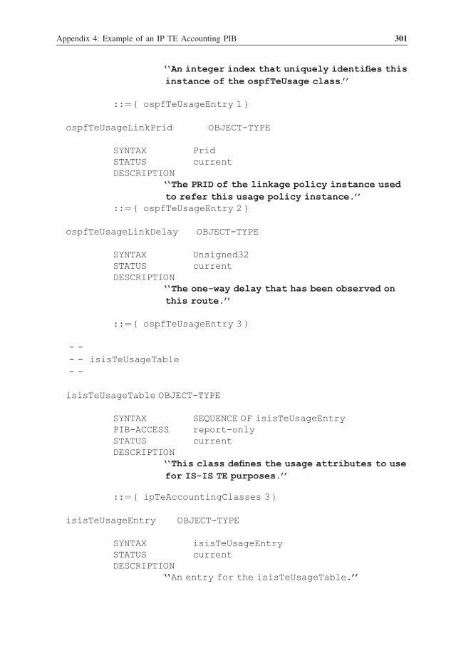
‘‘An integer index that uniquely identifies thisinstance of the ospfTeUsage class.’’
::¼ { ospfTeUsageEntry 1 }
ospfTeUsageLinkPrid OBJECT-TYPE
SYNTAX PridSTATUS currentDESCRIPTION
‘‘The PRID of the linkage policy instance usedto refer this usage policy instance.’’
::¼ { ospfTeUsageEntry 2 }
ospfTeUsageLinkDelay OBJECT-TYPE
SYNTAX Unsigned32STATUS currentDESCRIPTION
‘‘The one-way delay that has been observed onthis route.’’
::¼ { ospfTeUsageEntry 3 }
- -- - isisTeUsageTable- -
isisTeUsageTable OBJECT-TYPE
SYNTAX SEQUENCE OF isisTeUsageEntryPIB-ACCESS report-onlySTATUS currentDESCRIPTION
‘‘This class defines the usage attributes to usefor IS-IS TE purposes.’’
::¼ { ipTeAccountingClasses 3 }
isisTeUsageEntry OBJECT-TYPE
SYNTAX isisTeUsageEntrySTATUS currentDESCRIPTION
‘‘An entry for the isisTeUsageTable.’’
Appendix 4: Example of an IP TE Accounting PIB 301

PIB-INDEX { isisTeUsagePrid}UNIQUENESS { isisTeUsageLinkPrid,
isisTeUsageLinkDelay }
::¼ {isisTeUsageTable 1 }
isisTeUsageEntry: :¼ SEQUENCE {isisTeUsagePrid InstanceID,isisTeUsageLinkPrid Prid,
isisTeUsageLinkDelay Unsigned32 }
isisTeUsagePrid OBJECT-TYPESYNTAX PridSTATUS currentDESCRIPTION
‘‘An integer index that uniquely identifies thisinstance of the isisTeUsage class.’’
::¼ { isisTeUsageEntry 1 }
isisTeUsageLinkPrid OBJECT-TYPE
SYNTAX PridSTATUS currentDESCRIPTION
‘‘The PRID of the linkage policy instance usedto refer this usage policy instance.’’
::¼ { isisTeUsageEntry 2 }
isisTeUsageLinkDelay OBJECT-TYPE
SYNTAX Unsigned32STATUS currentDESCRIPTION
‘‘The one-way delay that has been observed onthis route.’’
::¼ { isisTeUsageEntry 3 }
- -- - bgpTeUsageTable- -
bgpTeTable OBJECT-TYPE
302 Service Automation and Dynamic Provisioning Techniques in IP/MPLS Environments

SYNTAX SEQUENCE OF bgpTeUsageEntryPIB-ACCESS report-onlySTATUS currentDESCRIPTION
‘‘This table contains a set of accountinginformation related to the activation of BGPprocess enabling exchange of QoS information.’’
: :¼ { ipTeAccountingClasses 4 }
bgpTeUsageEntry OBJECT-TYPE
SYNTAX bgpTeUsageEntrySTATUS currentDESCRIPTION
‘‘An entry to bgpTeUsage Class.’’
PIB-INDEX { bgpTeUsagePrid }UNIQUENESS { bgpTeUsageLinkPrid,
bgpTeUsageActIf,bgpTeUsageOneWayDelay }
::¼ { bgpTeUsageTable 1 }
bgpTeUsageEntry: :¼ SEQUENCE {bgpTeUsagePrid InstanceId,bgpTeUsageLinkPrid Prid,
bgpTeUsageActIf Counter64,bgpTeUsageOneWayDelay Unsigned32 }
bgpTeUsagePrid OBJECT-TYPE
SYNTAX InstanceIdSTATUS currentDESCRIPTION
‘‘An integer index that uniquely identifies thisinstance of the bgpTeUsage class.’’
: :¼ { bgpTeUsageEntry 1 }
bgpTeUsageLinkPrid OBJECT-TYPE
SYNTAX PridSTATUS current
Appendix 4: Example of an IP TE Accounting PIB 303

DESCRIPTION‘‘The PRID of the linkage policy instance usedto base this usage policy instance upon.’’
: :¼ { bgpTeUsageEntry 2 }
bgpTeUsageActIf OBJECT-TYPE
SYNTAX Counter64STATUS currentDESCRIPTION
‘‘Specifies the number of interfaces that areinvolved in the BGP route computation process.’’
: :¼ { bgpTeUsageEntry 3 }
bgpTeUsageOneWayDelay OBJECT-TYPE
SYNTAX Unsigned32STATUS currentDESCRIPTION
‘‘Specifies the one-way delay that has beenobserved on this route.’’
: :¼ { bgpTeUsageEntry 4 }
- -- - The Threshold class that accompanies the OSPF and BGP usage- - tables- -
- -- - OSPF threshold attributes- -
ospfTeThresholdTable OBJECT-TYPE
SYNTAX SEQUENCE OF ospfThresholdEntryPIB-ACCESS InstallSTATUS currentDESCRIPTION
‘‘This class defines the threshold attributescorresponding to OSPF TE usage attributesspecified in ospfTeUsageTable.’’
: :¼ { ipTeAccountingClasses 5 }
304 Service Automation and Dynamic Provisioning Techniques in IP/MPLS Environments

ospfTeThresholdEntry OBJECT-TYPE
SYNTAX ospfTeThresholdEntrySTATUS currentDESCRIPTION
‘‘Defines the attributes to hold threshold values.’’
PIB-INDEX { ospfTeThresholdId }
: :¼ { ospfTeThresholdId 1 }
ospfTeThresholdEntry::¼ SEQUENCE {ospfTeThresholdId InstanceID,ospfTeThresholdBwThresholds Integer64,ospfTeThresholdRsvBwThresholds Integer64 }
ospfTeThresholdId OBJECT-TYPE
SYNTAX InstanceIdSTATUS currentDESCRIPTION
‘‘Arbitrary integer index that uniquelyidentifies an instance of the class.’’
: :¼ { ospfTeThresholdEntry 1 }
ospfTeThresholdBwThresholds OBJECT-TYPE
SYNTAX Integer64STATUS currentDESCRIPTION
‘‘The threshold the used bandwidth on the linkshouldn't exceed.’’
: :¼ { ospfTeThresholdEntry 2 }
ospfTeThresholdRsvBwThresholds OBJECT-TYPE
SYNTAX Integer64STATUS currentDESCRIPTION
‘‘The threshold the reserved bandwidth on thelink shouldn't exceed.’’
Appendix 4: Example of an IP TE Accounting PIB 305

: :¼ { ospfTeThresholdEntry 3 }
- -- - ISIS Threshold attributes- -
isisTeThresholdTable OBJECT-TYPE
SYNTAX SEQUENCE OF isisThresholdEntryPIB-ACCESS InstallSTATUS currentDESCRIPTION
‘‘This class defines the threshold attributescorresponding to ISIS TE usage attributesspecified in isisTeUsageTable.’’
: :¼ { ipTeAccountingClasses 6 }
isisTeThresholdEntry OBJECT-TYPE
SYNTAX isisTeThresholdEntrySTATUS currentDESCRIPTION
‘‘Defines the attributes to hold thresholdvalues.’’
PIB-INDEX { isisTeThresholdId }
: :¼ { isisTeThresholdId 1 }
isisTeThresholdEntry::¼ SEQUENCE {isisTeThresholdId InstanceID,isisTeThresholdBwThresholds Integer64,isisTeThresholdRsvBwThresholds Integer64 }
isisTeThresholdId OBJECT-TYPE
SYNTAX InstanceIdSTATUS currentDESCRIPTION
‘‘Arbitrary integer index that uniquelyidentifies an instance of the class.’’
: :¼ { isisTeThresholdEntry 1 }
306 Service Automation and Dynamic Provisioning Techniques in IP/MPLS Environments

isisTeThresholdBwThresholds OBJECT-TYPE
SYNTAX Integer64STATUS currentDESCRIPTION
‘‘The threshold the used bandwidth on the linkshouldn't exceed.’’
: :¼ { isisTeThresholdEntry 2 }isisTeThresholdRsvBwThresholds OBJECT-TYPE
SYNTAX Integer64STATUS currentDESCRIPTION
‘‘The threshold the reserved bandwidth on thelink shouldn't exceed.’’
: :¼ { isisTeThresholdEntry 3 }
- -- - BGP threshold attributes- -
bgpTeThresholdTableOBJECT-TYPE
SYNTAX SEQUENCE OF bgpThresholdEntryPIB-ACCESS InstallSTATUS currentDESCRIPTION
‘‘This class defines the threshold attributescorresponding to BGP usage attributes specifiedin bgpTeUsageTable.’’
: :¼ { ipTeAccountingClasses 7 }
bgpTeThresholdEntry OBJECT-TYPE
SYNTAX bgpTeThresholdEntrySTATUS currentDESCRIPTION
‘‘Defines the attributes to hold thresholdvalues.’’
PIB-INDEX { bgpTeThresholdPrid }
Appendix 4: Example of an IP TE Accounting PIB 307

: :¼ { bgpTeThresholdId 1 }
bgpTeThresholdEntry: :¼ SEQUENCE {bgpTeThresholdId InstanceID,
bgpTeThresholdNlriAddress InetAddress,bgpTeThresholdNextHopAddress InetAddress,
bgpTeThresholdOneWayDelayThreshold Integer64,bgpTeThresholdInterPacketDelayThreshold
Integer64,bgpTeThresholdLossRateThreshold Integer64 }
bgpTeThresholdId OBJECT-TYPE
SYNTAX InstanceIdSTATUS currentDESCRIPTION
‘‘Arbitrary integer index that uniquelyidentifies an instance of the class.’’
: :¼ { bgpTeThresholdEntry 1 }
bgpTeThresholdNlriAddress OBJECT-TYPE
SYNTAX InetAddressSTATUS currentDESCRIPTION
‘‘The IP address to match against the NLRI fieldof QoS_NLRI attribute of the BGP-4 UPDATEmessage introduced in RFC 1771.’’
: :¼ { bgpTeThresholdEntry 2 }
bgpTeThresholdNextHopAddress OBJECT-TYPE
SYNTAX InetAddressSTATUS currentDESCRIPTION
‘‘The address of the next router.’’
: :¼ { bgpTeThresholdEntry 3 }
bgpTeThresholdOneWayDelayThreshold OBJECT-TYPE
SYNTAX Integer64STATUS current
308 Service Automation and Dynamic Provisioning Techniques in IP/MPLS Environments

DESCRIPTION‘‘The threshold of the one-way delay that willtrigger a report in the next reporting intervalwhen exceeded.’’
: :¼ { bgpTeThresholdEntry 4 }
bgpTeThresholdInterPacketDelayThreshold OBJECT-TYPE
SYNTAX Integer64STATUS currentDESCRIPTION
‘‘The threshold of the interpacket delayvariation that will trigger a report inthe next reporting interval when exceeded.’’
: :¼ { bgpTeThresholdEntry 5 }
bgpTeThresholdLossRateThreshold OBJECT-TYPE
SYNTAX Integer64STATUS currentDESCRIPTION
‘‘The threshold, in terms of loss rate, thatwill trigger a report in the next reportinginterval when exceeded.’’
: :¼ { bgpTeThresholdEntry 6 }
END
Appendix 4: Example of an IP TE Accounting PIB 309


APPENDIX 5
Description of Classes of an IPVPN Information Model
A5.1 Introduction
This appendix is the companion document of Chapter 10 ‘Automated Production of BGP/
MPLS-based VPNs’. It details the IP VPN-specific classes of an IP VPN information model
that can be used for the dynamic enforcement of IP VPN-specific policies.
A5.2 Policy Class Definitions
The class ipvpnPolicyVFICreationAction
This class specifies the VFI to be created in order dynamically todeploy a BGP/MPLS VPN.
NAME ipvpnPolicyVFICreationActionDESCRIPTION
The class for specifying the VFI to be created.DERIVED FROM PolicyActionABSTRACT FALSEPROPERTIES AttachedInterface [ref AccessEndPoint [1..n]]
The reference AttachedInterfaceThis is a reference to one or several objects of classAccessEndPoint.
The class ipvpnPolicyRouteDistributionActionThis action represents the route distribution process of an IP VPNrouting table that is implemented by means of RouteTarget andresults in the definition of routes with/without RouteDistingu-isher.
Service Automation and Dynamic Provisioning Techniques in IP/MPLS Environments
C. Jacquenet, G. Bourdon and M. Boucadair
# 2008 John Wiley & Sons Ltd

This action is intended to be used to implement RFC4364-compliantIP VPNs.
NAME ipvpnPolicyRouteDistributionActionDESCRIPTION
The class for representing the routedistribution actions. The distribution actionsshould support point-to-point, hub-and-spoke,full mesh and partial mesh topologyrequirements.
DERIVED FROM PolicyActionABSTRACT FALSEPROPERTIES DistributionSource [ref AccessEndPoint[1]]
DistributionDestination [ref AccessEndPoint[1]]DistributionMandatoryHops [refAccessEndPoint[0..n]]
The reference DistributionSource
This is a reference to an object of class AccessEndPoint.
The reference DistributionDestination
This is a reference to an object of class AccessEndPoint.
The reference DistributionMandatoryHops
This is a reference to zero or more objects, which points tomandatory hops to be used for the traffic flowing from theDistributionSource to the DistributionDestination. The objectsreferenced are instances of the class AccessEndPoint.
The class ipvpnPolicyVPNTopologyDescriptionAction
This class specifies the IP VPN service topology and reachabilityand is intended to be used for configuring an IP VPN database forimplementing IP VPNs.
NAME ipvpnPolicyVPNTopologyDescriptionActionDESCRIPTION The class for representing the topology and
reachability description actions. The actionsshould support point-to-point, hub-and-spoke,full mesh and partial mesh topologyrequirements.
DERIVED FROM PolicyActionABSTRACT FALSEPROPERTIES RoutingSource [ref AccessEndPoint [1]]
RoutingDestination [ref AccessEndPoint [1]]RoutingMandatoryHops [ref EdgeNode [2..n]]
The reference RoutingSource
This is a reference to an object of type AccessEndPoint.
312 Service Automation and Dynamic Provisioning Techniques in IP/MPLS Environments

The reference RoutingDestination
This is a reference to an object of type AccessEndPoint.
The reference RoutingMandatoryHops
This is a reference to zero or more objects, which points tomandatory hops to be used for the traffic flowing from theipvpnPolicyRoutingSource to the ipvpnPolicyRoutingDestination.The objects referenced are instance(s) of EdgeNode.
The class ipvpnPolicyNATActionThis class specifies which source addresses need to be translatedand what should be the results of this translation.
NAME ipvpnPolicyNATActionDESCRIPTION The class that represents the network address
translation action of the "If Condition thenAction" semantics associated with a policyrule.
DERIVED FROM PolicyActionABSTRACT FALSEPROPERTIES TranslateFromIPv4Address
TranslateToIPv4Address
The property TranslateFromIPv4Address
Specifies the original set of IPv4 addresses that needs to betranslated.
NAME TranslateFromIPv4AddressDESCRIPTION The original IPv4 address that needs to be
translated.SYNTAX PolicyIPv4AddrValue
The property TranslateToIPv4AddressSpecifies the final set of IPv4 addresses that needs to betranslated to.
NAME TranslateToIPv4AddressDESCRIPTION The final IPv4 address that needs to be
translated to.SYNTAX PolicyIPv4AddrValue
The class ipvpnPolicyTrafficTrunkAction
This class indicates the requirements on the traffic trunk to beused to transport the IP VPN traffic.
NAME ipvpnPolicyTrafficTrunkActionDESCRIPTION The class for representing the requirements of
the traffic trunk to be used to transport theVPN traffic
DERIVED FROM PolicyAction
Appendix 5: Description of Classes of an IP VPN Information Model 313

ABSTRACT FALSEPROPERTIES Ingress [ref EdgeNode]
Egress [ref EdgeNode]Priority [Integer]Preemption [Integer (1-4)]Resilience [boolean]TrafficProfile [QosPolicyTokenBucketTrfcProf]
The reference Ingress
This attribute references the Edge Node, which will be the ingressnode for the trunk.
The reference Egress
This attribute references the Edge Node, which will be the egressnode for the trunk.
The property Priority
This attribute indicates the priority requirement for the trunk.
NAME PriorityDESCRIPTION The priority requirement for the trunk.SYNTAX Integer
The property Preemption
This attribute indicates the preemption requirement for thetrunk.The preemption is related to whether the trunk can be preempted toaccommodate a new higher priority trunk.
NAME PreemptionDESCRIPTION The preemption requirement for the trunk.SYNTAX Integer(1-4)
The property ResilienceThis attribute indicates the resilience requirement for thetrunk.
NAME ResilienceDESCRIPTION The resilience requirement for the trunk.SYNTAX boolean
The property TrafficProfile
This attribute indicates the traffic profile requirement for thetrunk.
NAME TrafficProfileDESCRIPTION The Traffic Profile requirement for the trunk.SYNTAX QoSPolicyTokenBucketTrfcProf
314 Service Automation and Dynamic Provisioning Techniques in IP/MPLS Environments

The class ipvpnPolicyFirewallActionSpecifies the firewall action to be enforced such as "drop", "pass","log", "alert", etc. The list of possible actions is limited by theattributes in the action object.
NAME ipvpnPolicyFirewallActionDESCRIPTION The class for representing the firewall action
of the "If Condition then Action" semanticsassociated with a policy rule.
DERIVED FROM PolicyActionABSTRACT FALSEPROPERTIES Action
The property Action
The action defines the type of firewall action to be enforced.
NAME ActionDESCRIPTION The firewall action to be enforcedSYNTAX INTEGERVALUES The action can take the following values
0 ¼ Allow1 ¼ Allow and Log2 ¼ Allow and Alarm3 ¼ Deny4 ¼ Deny and Log5 ¼ Deny and Alarm
The class ipvpnEncryptionAction
The encryption standard is assumed to be IPsec. This class providesthe IPSec parameters that will be used to set up the securityassociation required to handle the encryption and decryption ofpackets.
NAME ipvpnEncryptionActionDESCRIPTION The class for representing the encryption
action of the "If Condition then Action"semantics associated with a policy rule.
DERIVED FROM PolicyActionABSTRACT TRUEPROPERTIES IkeAuthentication
IkeEncryptionIkeDHGroupIkeTimeoutIkeTrafficBasedExpiryIpsecAuthenticationIpsecEncryptionIpsecDHGroup
Appendix 5: Description of Classes of an IP VPN Information Model 315

IpsecTimeoutIpsecTrafficBasedExpiryIkePeerAuthenticationMethod
The property IkeAuthentication
The property specifies the authentication algorithm to be used. TheIkeAuthentication parameters can be used to generate thecorresponding ISA key management protocol (ISAKMP) parameters incases where ISAKMP is still being used. This draft does not des-cribe a separate set of parameters for ISAKMP. It is left to thepolicy servers generating the configuration to handle the corres-ponding translation.
NAME IkeAuthenticationDESCRIPTION The property that specifies the authentication
algorithm.SYNTAX String
The property IkeEncryption
The property specifies the encryption algorithm to be used.
NAME IkeEncryptionDESCRIPTION The property that specifies the encryption
algorithm.SYNTAX String
The property IkeDHGroup
The property specifies the DHGroup to be used during IKE negotia-tions.
NAME IkeDHGroupDESCRIPTION The property that specifies the DHGroup to be
used during IKE negotiations.SYNTAX String
The property IkeTimeout
The property specifies the IKE timeout to be used.
NAME IkeTimeoutDESCRIPTION The property that specifies the IKE timeout.SYNTAX Integer
The property IkeTrafficBasedExpiry
The property specifies the IKE traffic-based expiry to be used.
NAME IkeTrafficBasedExpiryDESCRIPTION The property that specifies the IKE traffic-
based expiry to be used.SYNTAX Integer
316 Service Automation and Dynamic Provisioning Techniques in IP/MPLS Environments

The property IPSECAuthentication
The property specifies the authentication algorithm to be used.
NAME IPSECAuthenticationDESCRIPTION The property that specifies the authentication
algorithm.SYNTAX String
The property IPSECEncryption
The property specifies the encryption algorithm to be used.
NAME IPSECEncryptionDESCRIPTION The property that specifies the encryption
algorithm.SYNTAX String
The property IPSECDHGroupThe property specifies the DHGroup to be used during IPsec negotia-tions.
NAME IPSECDHGroupDESCRIPTION The property that specifies the DHGroup to be
used during the IKE phase II negotiations.SYNTAX String
The property IPSECTimeout
The property specifies the IPsec key timeout to be used.
NAME IPSECTimeoutDESCRIPTION ThepropertythatspecifiestheIPSECkeytimeout.SYNTAX Integer
The property IPSECTrafficBasedExpiry
The property specifies the IPsec traffic-based key expiry to beused.
NAME IPSECTrafficBasedExpiryDESCRIPTION The property that specifies the IPsec traffic-
based key expiry to be used.SYNTAX Integer
The property IkePeerAuthenticationMethod
The IKE peers are the IKE processes that are at the two ends of acontrol channel related to encryption of traffic at the data layer.The method used by the Internet key exchange (IKE) peers toauthenticate each other. The IKE peers are running on the IP VPNnodes.
NAME IkePeerAuthenticationMethod
Appendix 5: Description of Classes of an IP VPN Information Model 317

DESCRIPTION The property that specifies the method used bythe IKE peers to authenticate each other.
SYNTAX Unsigned 16-bit integerVALUE The possible values are listed below.
0 ¼ ProposalList is to be used (see below)1 ¼ Preshared key2 ¼ DSS (D S S) signatures3 ¼ RSA (R S A) signatures4 ¼ Encryption with RSA5 ¼ Revised encryption with RSA6 ¼ Kerberos (has this number been assigned???)A value of 0 is a special value that indicatesthat this particular proposal should berepeated once for each authentication methodthat corresponds to the credentials installedon the machine. For example, if the system hasa preshared key and a certificate, a proposallist could be constructed that includes aproposal that specifies preshared key andproposals for any of the public-keyauthentication methods.DSS and RSA are encryption algorithms that areexplained in several encryption specific bookssuch as "Applied Cryptography".
The class ipvpnApplicaionSignatureValue
Specifies the layer-4 to layer-7 characteristics of the packet,including application level decodes that require statefulinspection of the packet, e.g. HTTP, FTP, SMTP, TELNET, etc. Thisclass enables the policies to capture the application layerrequirements of the customer with regards to treatment for spe-cific IP traffic.
NAME ipvpnApplicationSignatureValueDESCRIPTION The class for representing application
signature to be matched against the trafficDERIVED FROM qoSPolicyValueABSTRACT FALSEPROPERTIES applicationSignature
This class can have several subclasses, which reflect theapplication protocol classification granularity.
The property applicationSignature
NAME applicationSignatureDESCRIPTION The property that provides a signature used to
identify the application by examining thepayload of the protocol data unit (PDU).
318 Service Automation and Dynamic Provisioning Techniques in IP/MPLS Environments

SYNTAX String
Topology class definitions
The abstract class "Node"
The abstract class Node is a representation of a generic networknode. The class definition is as follows:
NAME NodeDESCRIPTION An abstract class representing a network node
entity.DERIVED FROM ComputerSystemABSTRACT TRUEPROPERTIES PEPIDThe PEPID single-valued property corresponds to the node ident-ifier. It is a globally unique identifier. The property definition isas follows:
NAME PEPIDDESCRIPTION A user-friendly name (e.g. DNS name or primary
IP public address) of a node object.SYNTAX String
The class "CoreNode"
The class CoreNode is a representation of a router residing at thenetwork core (with respect to the IP VPN service). The classdefinition is as follows:
NAME CoreNodeDESCRIPTION A class representing a network core router.DERIVED FROM NodeABSTRACT FALSEPROPERTIES NONE
The class "EdgeNode"
The class EdgeNode is a representation of a router residing at thenetwork edge (with respect to the IP VPN service). The classdefinition is as follows:
NAME EdgeNodeDESCRIPTION A class representing a network edge router.DERIVED FROM NodeABSTRACT FALSEPROPERTIES NONE
The class "LogicalNetwork"
The class LogicalNetwork is defined by DMTF. It is reported here forconvenience. A LogicalNetwork groups together a set of
Appendix 5: Description of Classes of an IP VPN Information Model 319

ProtocolEndpoints of a given type that are able to communicatewith each other directly. A LogicalNetwork represents the abilityto send and/or receive data over a network. The class definition isas follows:
NAME LogicalNetworkDESCRIPTION A class representing a logical network.DERIVED FROM CollectionOfMSEsABSTRACT FALSEPROPERTIES NetworkType
The NetworkType single-valued property provides additionalinformation that can be used to help categorize and classifydifferent instances of this class. The property takes values froman enumeration. Some possible values are "Unknown", "Other","IPv4", "IPv6", "IPX", etc. The property definition is as follows:
NAME NetworkTypeDESCRIPTION Specify the network type.SYNTAX String
The class "Partition"
The provider network is partitioned into domains called"partitions". A partition is an administrative entity. The classdefinition is as follows:
NAME PartitionDESCRIPTION An class representing a (logical) partition.DERIVED FROM LogicalNetworkABSTRACT FALSEPROPERTIES PartitionID
The PartitionID single-valued property corresponds to the parti-tion identifier. It is unique within the scope of a provider domain.The property definition is as follows:NAME PartitionIDDESCRIPTION A user-friendly name of a partition object.SYNTAX String
The class "IP VPN"
The class IP VPN represents an IP virtual private network deployedwithin the provider network. The class definition is as follows:
NAME IP VPNDESCRIPTION A class representing an IP VPN.DERIVED FROM LogicalNetworkABSTRACT FALSEPROPERTIES VPNID
320 Service Automation and Dynamic Provisioning Techniques in IP/MPLS Environments

The VPNID single-valued property corresponds to the globallyunique VPN identifier as defined by IETF. The property definition isas follows:
NAME VPNIDDESCRIPTION The standard VPNID.SYNTAX Octet
The class "ProtocolEndPoint"
The class ProtocolEndPoint is defined by DMTF. It is reported herefor convenience. The class represents a communication point fromwhich data may be sent or received. ProtocolEndPoints link routerinterfaces and switch ports to LogicalNetworks. The class defini-tion is as follows:
NAME ProtocolEndPointDESCRIPTION A communication point.DERIVED FROM ServiceAccessPointABSTRACT FALSEPROPERTIES ProtocolType
The ProtocolType single-valued property provides additionalinformation that can be used to help categorize and classifydifferent instances of this class. The property takes values froman enumeration. Some possible values are "Unknown", "Other","IPv4", "IPv6", "IPX", etc. The property definition is as follows:
NAME ProtocolTypeDESCRIPTION Specify the protocol of endpoint.SYNTAX String
The class "AccessEndPoint"
The class AccessEndPoint represents an access IP interface. Theclass definition is as follows:
NAME AccessEndPointDESCRIPTION A class representing an access interface.DERIVED FROM ProtocolEndPointABSTRACT FALSEPROPERTIES NONE
The class "CoreEndPoint"
The class CoreEndPoint represents a core IP interface. The classdefinition is as follows:
NAME CoreEndPointDESCRIPTION A class representing a core interface.DERIVED FROM ProtocolEndPointABSTRACT FALSE
Appendix 5: Description of Classes of an IP VPN Information Model 321

PROPERTIES IPAddress
The class "VirtualEndPoint"
The class VirtualEndPoint represents a virtual interface (e.g. atunnel endpoint). The class definition is as follows:
NAME VirtualEndPointDESCRIPTION A class representing a virtual interface.DERIVED FROM ProtocolEndPointABSTRACT FALSEPROPERTIES NONE
The abstract class "NetworkService"
The class NetworkService is defined by DMTF. It is reported here forconvenience. This is an abstract base class. It serves as the rootof the network hierarchy. Network services represent genericfunctions that are available from the network that configure and/or modify the traffic being sent. The class definition is as follows:
NAME NetworkServiceDESCRIPTION A class representing a base network service.DERIVED FROM ServiceABSTRACT TRUEPROPERTIES NONE
//string StartupConditions [ ]//string StartupParameters [ ]
The class "VirtualForwardingInstance"
This class represents a VFI. A VFI is a dedicated forwardingprocess that runs on a border router (i.e. a PE or a CE). VFI forwa-rds customer traffic of a given IP VPN to the virtual links, and viceversa. Hence a VFI is associated with a subset of the accessinterfaces and virtual interfaces of a border node. The classdefinition is as follows:
NAME VirtualForwardingInstanceDESCRIPTION A class representing a VFI.DERIVED FROM NetworkServiceABSTRACT FALSEPROPERTIES VPNID
The following classes define the "associations" that belong to thetopology model.
The abstract association "Link"
This abstract association is used to represent a bidirectionallink. The class definition for the association is as follows:
322 Service Automation and Dynamic Provisioning Techniques in IP/MPLS Environments

NAME LinkDESCRIPTION A generic association used to establish a one-
to-one bidirectional relationship between thesubclasses of ProtocolEndPoint.
DERIVED FROM DependencyABSTRACT TRUEPROPERTIES Antecedent [ref ProtocolEndPoint [1..1]]
Dependent [ref ProtocolEndPoint [1..1]]
This abstract association inherits two object references from ahigher-level CIM association class, Dependency. It overridesthese object references to make them references to instances ofthe class ProtocolEndPoint. Subclasses of Link then overridethese object references again, to make them references to concr-rete "interface" classes.Note that the semantic of dependent and antecedent properties ischanged. These properties just represent a pair of unorderedassociation ends. The [1..1] cardinality indicates that a pair ofProtocolEndpoints can be connected by exactly one Link.
The association "CoreLink"
This association is used to represent a direct reachability bet-ween two core interfaces. Interfaces can belong to either ENs orCNs. The class definition for the association is as follows:
NAME CoreLinkDESCRIPTION A logical representation of a one-hop
reachability between two nodes.DERIVED FROM LinkABSTRACT FALSEPROPERTIES Antecedent [ref CoreEndPoint[1..1]]
Dependent [ref CoreEndPoint [1..1]]
This association is a concrete class and can be instantiated. Itinherits two object references from the Link class and overridesthese object references to make them references to instances ofthe class CoreEndPoint.
The association "AccessLink"
This association is used to represent a direct reachability bet-ween two access interfaces. The class definition for the associat-ion is as follows:
NAME AccessLinkDESCRIPTION A logical representation of a one-hop
reachability between a border node and acustomer node.
DERIVED FROM Link
Appendix 5: Description of Classes of an IP VPN Information Model 323

ABSTRACT FALSEPROPERTIES Antecedent [ref AccessEndPoint [1..1]]
Dependent [ref AccessEndPoint [1..1]]
This association is a concrete class. It inherits two objectreferences from the Link class and overrides these object refer-ences to make them references to instances of the class AccessEnd-Point.
The association "VirtualLink"
This association is used to represent a virtual one-hop reach-ability (e.g. a tunnel or a MPLS LSP) between two virtual inter-faces. The class definition for the association is as follows:
NAME VirtualLinkDESCRIPTION A logical representation of a virtual
connection traversing the core network.DERIVED FROM LinkABSTRACT FALSEPROPERTIES Antecedent [ref VirtualEndPoint [1..1]]
Dependent [ref VirtualEndPoint [1..1]]
This association inherits two object references from the Linkclass. It overrides these object references to make them refer-ences to instances of the class VirtualEndPoint.
The abstract association "NodeInPartition"
The class definition for the association is as follows:
NAME NodeInPartitionDESCRIPTION A generic association used to establish a
relationship between a generic node and itspertaining partition.
DERIVED FROM DependencyABSTRACT TRUEPROPERTIES Antecedent [ref Node [0..*]]
Dependent [ref Partition [1..1]]
This abstract association inherits two object references from ahigher-levelCIMassociationclass,Dependency.Itoverridestheseobject references to make them references to instances of theclass Node and Partition. Subclasses of NodeInPartition thenoverride the antecedent references again, to make them referencesto concrete subclasses of Node.
The association "EdgeNodeInPartition"
The class definition for the association is as follows:
NAME EdgeNodeInPartitionDESCRIPTION The association represents the relationship
324 Service Automation and Dynamic Provisioning Techniques in IP/MPLS Environments

between an EdgeNode and its pertainingPartition.
DERIVED FROM NodeInPartitionABSTRACT FALSEPROPERTIES Antecedent [ref EdgeNode [2..*]]
The association "CoreNodeInPartition"
The class definition for the association is as follows:
NAME CoreNodeInPartitionDESCRIPTION The association represents the relationship
between a CoreNode and its pertainingPartition.
DERIVED FROM NodeInPartitionABSTRACT FALSEPROPERTIES Antecedent [ref CoreNode [0..*]]
The association "AccessEndPointInVFI"
The class definition for the association is as follows:
NAME AccessEndPointInVFIDESCRIPTION An association used to establish a relationship
between a VFI and the access interfaces itserves.
DERIVED FROM DependencyABSTRACT FALSEPROPERTIES Antecedent [ref AccessEndPoint [1..*]]
Dependent [ref VirtualForwardingInstance[1..1]]
This association inherits two object references from a higher-level CIM association class, Dependency. It overrides these obj-ect references to make them references to instances of the classesAccessEndPoint and VirtualForwardingInstance.
The association "VirtualEndPointInVFI"
The class definition for the association is as follows:
NAME VirtualEndPointInVFIDESCRIPTION A generic association used to establish a
relationship between a VFI and the virtualinterfaces it works on.
DERIVED FROM DependencyABSTRACT FALSEPROPERTIES Antecedent [ref VirtualEndPoint [1..*]]
Dependent [ref VirtualForwardingInstance [1..1]]
This association inherits two object references from a higher-level CIM association class, Dependency. It overrides these obj-ect references to make them references to instances of the classes
Appendix 5: Description of Classes of an IP VPN Information Model 325

VirtualEndPoint and VirtualForwardingInstance.
The abstract aggregation "ProtocolEndPointInNode"
This abstract aggregation defines two object references that willbe overridden in each of five subclasses, to become references tothe subclasses of Node and ProtocolEndPoint. From a general view-point, this aggregation expresses what interfaces (physical orvirtual) belong to a given node. The class definition for the aggre-gation is as follows:
NAME ProtocolEndPointInNodeDESCRIPTION A generic association used to establish a
relationship between a generic node and itsinterfaces.
DERIVED FROM ComponentABSTRACT TRUEPROPERTIES GroupComponent [ref Node [0..*]]
PartComponent [ref ProtocolEndPoint [0..*]]
The aggregation "AccessEndPointInEdgeNode"
The AccessEndPointInEdgeNode aggregation enables access inter-faces to be assigned to a given EN. The class definition for theaggregation is as follows:
NAME AccessEndPointInEdgeNodeDESCRIPTION A class representing the aggregation of access
interfaces by ENs.DERIVED FROM ProtocolEndPointInNodeABSTRACT FALSEPROPERTIES GroupComponent [ref EdgeNode [1..1]]
PartComponent [ref AccessEndPoint [1..*]]
The aggregation "CoreEndPointInEdgeNode"
The CoreEndPointInEdgeNode aggregation enables core interfacesto be assigned to a given EN. The class definition for the aggrega-tion is as follows:
NAME CoreEndPointInEdgeNodeDESCRIPTION A class representing the aggregation of core
interfaces by ENs.DERIVED FROM ProtocolEndPointInNodeABSTRACT FALSEPROPERTIES GroupComponent [ref EdgeNode [1..1]]
PartComponent [ref CoreEndPoint [1..*]]
The aggregation "CoreEndPointInCoreNode"
The CoreEndPointInCoreNode aggregation enables core interfacesto be assigned to a given core router. The class definition for the
326 Service Automation and Dynamic Provisioning Techniques in IP/MPLS Environments

aggregation is as follows:
NAME CoreEndPointInCoreNodeDESCRIPTION A class representing the aggregation of core
interfaces by CNs.DERIVED FROM ProtocolEndPointInNodeABSTRACT FALSEPROPERTIES GroupComponent [ref CoreNode [1..1]]
PartComponent [ref CoreEndPoint [2..*]]
The aggregation "VirtualEndPointInEdgeNode"
The VirtualEndPointInEdgeNode aggregation enables virtual int-erfaces to be assigned to a given EN. The class definition for theaggregation is as follows:
NAME VirtualEndPointInEdgeNodeDESCRIPTION A class representing the aggregation of virtual
interfaces by PEs.DERIVED FROM ProtocolEndPointInNodeABSTRACT FALSEPROPERTIES GroupComponent [ref EdgeNode [1..1]]
PartComponent [ref VirtualEndPoint [0..*]]
The aggregation "VFIInEdgeNode"
Each VFI works in an EN. This class associates VFIs with corres-ponding border routers. The class definition for the aggregationis as follows:
NAME VFIInEdgeNodeDESCRIPTION Aggregation between a VFI and an EN.DERIVED FROM ComponentABSTRACT FALSEPROPERTIES GroupComponent [ref EdgeNode [1..1]]
PartComponent [refVirtualForwardingInstance [0..*]]
The aggregation "EdgeNodeInIPVPN"
This association identifies which border routers are serving an IPVPN. The class definition for the aggregation is as follows:
NAME EdgeNodeInIPVPNDESCRIPTION Aggregation between an EN and an IP VPN.DERIVED FROM ComponentABSTRACT FALSEPROPERTIES GroupComponent [ref IP VPN [1..1]]
PartComponent [ref EdgeNode [2..*]]
Appendix 5: Description of Classes of an IP VPN Information Model 327


Index
3GPP, 27, 58, 61, 81, 82, 83, 89
802.11i, 27, 234
802.1X, 235, 236, 237, 238
Abort-Session-Request/Answer, 75, 77
Access-Accept, 28, 29, 30, 31, 33, 34, 35, 37, 39,
40, 41, 42, 45, 46, 47, 48, 49, 50, 51, 52, 55,
77, 230, 231, 233, 237, 238
Access-Challenge, 29, 30, 31, 34, 35, 38, 41, 45,
46, 77
Access Controller (AC), 177, 178, 179, 180, 181,
182, 183, 184, 185, 186
Access-List (ACL), 236, 237
Access Network, 214
Access Point (AP), 176, 177, 181, 182
Access-Reject, 28, 29, 30, 31, 34, 35, 36, 45, 46,
47, 51, 77)
Access-Request, 28, 29, 30, 31, 34, 35, 36, 38,
39, 46, 50, 51, 55, 77, 230, 233
Access-Resource and Admission Control
Function (A-RACF), 86, 87, 88, 89
Accounting-Auth-Method, 78
Accounting-Input-Octets, 78
Accounting-Input-Packets, 78
Accounting-Off, 31, 38
Accounting-On, 31, 38
Accounting-Output-Octets, 78
Accounting-Output-Packets, 78
Accounting-Realtime-Required, 76
Accounting-Record-Type, 76, 78
Accounting-Request (RADIUS), 29, 30, 31,
38, 47, 48, 50, 51, 52, 53, 55, 231
Accounting-Request/Answer (Diameter), 68,
75, 77
Accounting-Response (RADIUS), 29, 31, 35, 47
Accounting start, 31, 38, 47, 48, 50
Accounting stop, 31, 47, 48, 50
Acct-Interim-Interval, 48
Acct-Multi-Session-Id, 48
Acct-NAS-Traffic-Rule, 54
Acct-Session-Id, 49
Acct-Status-Type, 31, 47, 48, 57
Acct-Termination-Cause, 48
Application function (AF), 85, 86, 87, 89
Application identifier, 72
Application server (AS), 85
Audit events, 117
Authentication methods, 108
Automation, 15
Autonomous WLAN architecture, 178
Bandwidth-Profile-Id, 55
Basic Service Set (BSS), 177
BEEP, 106, 108, 109, 114, 153
BGP, 4, 9, 211
Border Gateway Function (BGF), 83, 86, 87,
88, 89
Callback-Number, 40
Call session control function (CSCF), 85
Candidate datastore, 118, 144, 171
Capabilities-Exchange-Request/Answer, 74
Capability, 116, 118, 162
Captive portal, 227, 228, 230, 232, 233
Centralized WLAN architecture, 178
Change-of-Authorization, 41, 49, 52
CHAP-Algorithm, 77
CHAP-Auth, 77
CHAP-Ident, 77
CHAP-Password, 32
CHAP-Response, 77
Chillispot, 228
Service Automation and Dynamic Provisioning Techniques in IP/MPLS Environments C. Jacquenet,
G. Bourdon and M. Boucadair
# 2008 John Wiley & Sons Ltd

CIM, 106
Cisco-AVPair, 233, 237
Cisco-SSG-Account-Info, 233, 234
Cisco-SSG-Command-Code, 234
Cisco-SSG-Control-Info, 234
Cisco-SSG-Service-Info, 233, 234
Class, 23, 103, 220
Client-Type, 92, 204
C-Num, 95
CoA, 49, 55
CoA-ACK, 49, 50
CoA-NAK, 49, 51
Command code, 72
Command flags, 71
Configuration data, 117
Configuration events, 117
Containment node, 130
Content layer, 115
Content match node, 130
COPS, 91, 106
messages, 95, 97
COPS-PR, 101
Core IMS, 85
Credit control, 38, 48, 49, 55, 58, 67, 81, 82
Credit-Control-Request/Answer, 82
CTP, 182
Datastores, 118
DEN, 106
Destination-Host, 68, 69
Destination-Realm, 66, 68, 69, 70
Device-Watchdog-Request/Answer, 74
Diameter agent, 66, 74, 75
Diameter client, 65, 66, 68, 69, 70, 72
Diameter connection, 67
Diameter proxy agent, 66
Diameter redirect agent, 67
Diameter relay agent, 66
Diameter server, 65, 66, 68, 69, 70, 75, 76, 89
Diameter session, 67
Diameter translation agent, 67, 72
DiffServ, 190, 192
Disconnect-ACK, 49
Disconnect-NAK, 49
Disconnect-Peer-Request/Answer, 74
Disconnect-Request, 49, 23
Disconnect-Response, 233
Distance vector, 6, 7
Distributed WLAN architecture, 178
Distribution System (DS), 177
DSCP, 190
DTLS, 183, 184, 185
EAP, 28, 31, 44, 45, 46, 47, 57
EAP Failure, 45, 47
EAP-Message, 44, 45, 46
EAPoL, 28, 237
EAP Request, 45, 46
EAP Response, 45, 46
EAP Success, 45, 46
EGP, 5
Egress-Bandwidth, 55
Egress-VLANID, 52
End-to-End Identifier, 72
Enterprise code, 33, 42, 43
EPD, 102
ETSI/TISPAN, 61, 81, 82, 83, 85, 89
EVENT Record, 76
Extended Service Set (ESS), 177
Extensible Markup Language, 110
Fault events, 117
FIB, 4, 201
Filter, 129, 130, 135, 152, 165
Filter-Id, 33, 40, 41, 42, 43, 44, 52, 53, 54, 55,
80, 237
Feltering, 129
Framed-Compression, 40
Framed-IP-Address, 33, 39, 40, 49
Framed-IP-Netmask, 33, 40
Framed-MTU, 40
Framed-Protocol, 39
Framed-Route, 40
Framed-Routing, 40
Heartbeat events, 117
Hop-by-Hop Identifier, 72
HTML, 111
Idle-Timeout, 40
IETF, 106, 107, 115
IGP, 4, 5
IMS, 58, 59, 61, 82, 83, 85, 86
Ingress-Bandwidth, 54
Ingress-Filters, 52
Inheritance, 220
interface e4, 88
interface Gq, 89, 90
interface Ia, 89
interface Ra, 89
330 Index

interface Re, 89
interface Rq, 89
Interim accounting update, 47
INTERIM records, 76
Interim-Update, 31, 37, 38, 48
Internet Architecture Board, 106
IP, 3, 199, 211
filter rule, 52
sphere forum, 242
Keep-alive, 36
Label, 11
LDAP, 214
Link state, 6, 7
Local MAC, 178, 179, 180, 181, 183
LPDP, 92, 201
LWAPP, 176, 182, 183
Maintenance events, 117
Managed device, 105, 114, 115, 116
Managed entity, 114
Management application, 114, 116, 117
Message length, 71
Message types, 30
Message-Authenticator, 45, 46
Metric, 4, 205
events, 117
MIB, 106
MOBILEIP, 62
Model, 215
MPLS, 10, 105, 199, 211
Namespace, 111
selection, 130
NAS-Filter-Rule (Diameter), 77, 78, 79, 81
NAS-Filter-Rule (RADIUS), 52, 53, 54
NAS-IP-Address, 32
NAS-Port, 32
NASREQ, 61, 62, 67, 69, 76, 77, 78, 81, 82, 90
NAS-Traffic-Rule, 54
Negative response, 135
NETCONF, 105, 106
client, 105
data, 117
device, 163
NETMOD, 116, 173
Network, 4, 214
providers, 106
Network access identifier, 32, 56, 57
Network Address Identifier (NAI),
63, 69
Network attachment subsystem (NASS), 83, 85,
86, 88
NGN, 61, 82, 83, 85, 89
Notification, 108, 117, 135, 149
One way RPC, 120
Operations and Management Area, 106
Operations Layer, 115
Origin-State-Id, 76
Outsourcing mode, 100
PCEP, 94
PDP, 22, 92, 101, 201
Peer table, 68
PEP, 23, 92, 101, 201
PIB, 106, 23, 206
Policy, 14, 19, 193, 199, 213
Port-Limit, 40
Positive response, 135
PRC, 23, 103
PRI, 23, 103
PRID, 23, 203
Provider network, 214
Provisioning mode, 101
Proxy CSCF (P-CSCF), 85, 86, 89
Pull Mode, 49, 50
Push Mode, 49
QoS, 189
QoS-Filter-Rule, 77, 78, 79, 80, 81
RADIUS authenticator field, 29, 30, 31, 32, 44,
45, 46, 49
RADIUS client, 28, 31, 32, 33, 35, 36, 37, 38,
39, 41, 45, 46, 47, 49, 50, 51, 56
RADIUS exchanges, 34
RADIUS identifier field, 29, 31, 36
RADIUS length field, 29, 34
RADIUS message code field, 29, 31, 33, 34
RADIUS Retransmission Rules, 36
RADIUS server, 27, 30, 34, 35, 36, 37, 38, 39,
41, 42, 45, 46, 47, 50, 51, 52, 56, 57
RAP, 107
Realm-based routing table, 68
Re-Auth-Request/Answer, 75, 77, 81
Remote MAC, 178, 179
Reply-message, 41
REQ, 97, 202
Index 331

Resource and admission control subsystem
(RACS), 84, 85, 86, 87, 88, 89
Resource Control Enforcement Function
(RCEF), 86, 87, 88, 89
Retrieval mechanisms, 107
RIB, 4, 201
RFC, 106
ROAMOPS, 62
Rollback capability, 108
Router, 3
RPC, 115
layer, 115
RPT, 97, 203
Rule, 19, 197, 214
Running datastore, 118
Selection node, 130
Self-Organizing Networks, 248
Service, 14
providers, 106
Service-based Policy Decision Function (SPDF),
86, 87, 88, 89
Service selection gateway (SSG), 228, 229, 230,
231, 232, 233, 234
Service-Type, 39, 50, 51, 57
Session, 116, 118, 142
Session initiation protocol (SIP), 67, 82, 85, 86
Session-Termination-Request/Answer, 75, 77
SLAPP, 182, 183
SLS, 192, 196, 213
S-Num, 102
SOA, 242
SOAP, 109
SON, 248
Split MAC, 178, 179, 180, 181, 183
SSH, 109
SSS, 242
START record, 76
Startup datastore, 118
State data, 117
STOP record, 76
S-Type, 102
Subscriber edge services manager (SESM), 228,
229, 230, 231, 232, 233, 234
Subtree filtering, 129
TEQUILA, 196
Termination-Action, 40
Traffic engineering, 191, 199
Transfer functions, 83
Transport layer, 114
Tunneling, 78
Two way RPC, 120
URN, 118
User-Name, 32, 49
User-Password, 32
User-Priority-Table, 52
Vendor-Specific Attribute (VSA), 32, 33, 35, 40,
41, 42, 43, 52, 54, 56, 80
Version field, 71
VLAN-Name, 52
VoIP, 105
VPN, 105
WICOP, 182
Wi-Fi, 175, 182, 227, 228, 233, 234,
235, 238
Wireless Termination Point (WTP), 177, 178,
179, 180, 181, 182, 183, 184, 185, 186
WLAN, 175, 176, 177, 178, 179, 180, 181, 182,
183, 186
WPA/WPA2, 234, 238
XML attributes, 110
XML comment, 111
XMLCONF, 108
XML document, 110
XML tag, 110
<close-session>, 116, 135, 142
<commit>, 135, 148, 149, 167
<copy-config>, 115, 131, 138
<delete-config>, 115, 131, 137
<discard-changes>, 135, 149
<edit-config>, 131, 139, 140
<get>, 115, 117, 131
<get-config>, 117, 135, 136
<kill-session>, 116, 135, 143
<lock>, 131, 144, 145
<notification>, 135, 150, 171
<ok>, 123, 124, 125
<rpc>, 115
<rpc-error>, 122, 124
<rpc-reply>, 115, 122
<subscribe-notification>, 135, 171
<unlock>, 135, 145
<validate>, 135, 146, 164
332 Index