service. 2018 - e-goksu.come-goksu.com/.../app_data/brosur/mfz/180328_17_mfz_all_cataloge.pdf ·...
TRANSCRIPT

SERVICE.
DIVERSITY.
QUALITY.
INDIVIDUAL SOLUTIONS.
THIS IS WHAT
DRIVES US.
2018
www.mfz-antriebe.de

ROLLER SHUTTER DRIVESwww.mfz-antriebe.de

1
Slip-on drives Starting on page 6
MDF / MWF
2
Box slip-on drivesStarting on page 14
DF / WF
3
Chain drivesStarting on page 18
KD
Section on roller shutter drives
ROLLER SHUTTER DRIVES
5

MDF / MWFMDF Three-phase a.c. slip-on drives for roller shutters and roller grilles with integrated safety catch device MWF Single-phase a.c. slip-on drives for roller shutters and roller grilles with integrated safety catch device
The MDF and MWF series of MFZ slip-on drives are characterised by their compact design, facilitating the widest range of installation possibilities. The maintenance-free safety catch device is already integrated and therefore provides the safest solution for the gate. With a complete series from 100 to 2000 Nm, MFZ provides the right solution in this category for every on-site situation. We also have the flexibility to quickly realise custom solutions for individual customer requirements at any time.
Integrated safety catch device, independent of position and speed, free of maintenance and wear, integrated damping
Self-aligning bearings
Rolled worm shaft
Dimension between centre lines 145 mm or 120 mm (only for MDF 20 / MDF 30)
Emergency operation via emergency hand crank (KU) (1-sided or 2-sided) or emergency hand chain (KE)
Straightforward conversion from crank to chain
End position setting via electronic absolute encoder ormechanical limit switch
Thermal protection in the motor windings
Higher motor duty cycle available. Identified by the addendum HD
Supply 230 / 400V / 50Hz / 3~ or 230V / 50Hz / 1~(custom solutions on request)
Plug-in connections
Version with external control, for combination with an extensive control programme. Supply: 230 / 400V / 3~, 230V / 1~ Frequency: 50 / 60 HzControl voltage: 24V-DC (Section 10 “Controls”)
Frequency converter control optional. Increasing the drive motor speed (operation with frequency converter) reduces the drive torque.The following applies in this case: Increasing the drive motor speed by 10% reduces the drive torque by 5%.
Custom versions, such as different voltages and frequencies, other drive motor speeds, higher protection classes and hollow shaft diameters on request.
ATEX versions (Section 7 “Drives for use in explosion protected rooms)
Characteristics
01
10
11
12
13
14
15
02
03
04
05
06
07
08
09
MDF / MWF 30MDF / MWF 05 MDF / MWF 20 MDF 50
www.mfz-antriebe.de
6

Rolle
r shu
tter d
rives
1
1
MDF 60 MDF 70
ROLLER SHUTTER DRIVES
13
HD
MDF
/ M
WF
KU KE
02 04 05
09 1107
1512
7

8
Selecting the right slip-on drive
SUSPENDED WEIGHTS
To select the optimum drive solution, you will need the diameter of the winding shaft in mm and the suspended weight of the door in kg. With the help of these parameters, the appropriate roller shutter drive can be determined easily and reliably using this table.The assignment can also be realised using the free MFZ Calculation app.
Maximum suspended weight in kg
The values in the table take into account 20% safety reserve and a lamella thickness of 25 mm. In certain situations, e.g. for additional door seals or double skin profiles, the friction can be greater and this must be considered when calculating the values. A drive with a higher duty cycle (HD) should be chosen for door systems with above-average switching cycles.
133,0
108,0
101,6
159,0
177,8
193,7
244,5
273,0
298,5
323,9
Straightforward drive selection
Diameter Winding shaft Suspended weight
Diameter (Ø outside) of the winding shaft in mm
MDF 05-10-12 HD 129 123 103 89 80 75 67 61 55 50 47MDF 05-14-12 180 172 145 124 113 104 94 85 77 71 65MDF 20-15-12 HD 193 184 155 133 121 112 100 91 82 76 70MDF 20-22-12 283 270 227 195 177 164 147 133 120 111 103MDF 30-27-12 HD 348 331 279 239 217 201 180 163 148 136 126MDF 30-30-12 386 368 310 266 241 224 201 182 164 151 140MDF 30-42-12 541 515 434 372 338 313 281 254 230 212 196MDF 30-50-12 644 613 516 443 402 373 334 303 274 252 234MDF 50-65-10 HD 837 797 671 576 523 485 434 393 356 328 304MDF 50-75-10 966 920 774 665 603 559 501 454 410 378 351MDF 60-100-9 1288 1226 1032 886 804 746 668 605 547 504 467MDF 60-140-9 HD 1804 1717 1445 1241 1126 1044 935 847 766 706 654MDF 70-165-8 HD 2126 2023 1703 1463 1327 1231 1102 999 903 832 771MDF 70-200-8 HD 2577 2453 2065 1773 1608 1492 1336 1210 1095 1008 935
MWF 05-14-12 180 172 145 124 113 104 94 85 77 71 65MWF 20-22-12 283 270 227 195 177 164 147 133 120 111 103MWF 30-28-12 361 343 289 248 225 209 187 169 153 141 131MWF 30-38-12 490 466 392 337 306 283 254 230 208 192 178
MDF 05-14-24 180 172 145 124 113 104 94 85 77 71 65MDF 20-18-24 232 221 186 160 145 134 120 109 99 91 84MDF 30-32-24 412 392 330 284 257 239 214 194 175 161 150MDF 30-40-24 515 491 413 355 322 298 267 242 219 202 187MDF 50-75-24 HD 966 920 774 665 603 559 501 454 410 378 351MDF 60-100-24 HD 1288 1226 1032 886 804 746 668 605 547 504 467MDF 70-125-24 HD 1610 1533 1290 1108 1005 932 835 756 684 630 584MDF 70-165-24 HD 2126 2023 1703 1463 1327 1231 1102 999 903 832 771
219,1
HD
HD
HD
HD
kgØ Drive+ =
www.mfz-antriebe.de
MDF
/ M
WF
Rolle
r shu
tter d
rives
1
HD
HD
HD
HD
HD
HD
HD

Slip-on drives for roller shutters and roller grilles with integrated safety catch device
TECHNICAL DATA
MDF 0
5-10
-12 H
D
MDF 2
0-15
-12 H
D
MDF 0
5-14
-12
MDF 2
0-22
-12
MDF 0
5-14
-24
MWF 0
5-14
-12
MWF 2
0-22
-12
MDF 2
0-18
-24
Drive torque Nm 140 100 140 140 220 150 220 180Drive motor speed min -1 12 12 12 24 12 24 12 12Maximum safety catch torque Nm 309 309 309 692 784 784 784 784Certificate no. of the safety catch device Door FV 6 / 092 Door FV 6 / 092 / 1 Door FV 9 / 147 / 1
Motor output kW 0,45 0,37 0,4 0,55 0,75 0,55 0,6 1,1Operating voltage V 230 / 400 / 3~ 230 / 400 / 3~ 230 / 1~ 230 / 400 / 3~ 230 / 400 / 3~ 230 / 400 / 3~ 230 / 1~ 230 / 400 / 3~
Mains frequency Hz 50 50 50 50 50 50 50 50Control voltage V 24 24 24 24 24 24 24 24Motor current rating A 3,3 / 1,9 2,6 / 1,5 6,5 3,0 / 1,7 4,8 / 2,8 3,1 / 1,8 9,0 4,7 / 2,7Max. cycles per hour * 20 30 5 20 20 30 5 20Fuse protection, on site (mains operation)
A 10 10 10 10 10 10 10 10
IP protection class 54 54 54 54 54 54 54 54 Temperature range ** °C –20 / +60 –20 / +60 –20 / +60 –20 / +60 –20 / +60 –20 / +60 –20 / +60 –20 / +60Continuous sound pressure level dB (A) < 70 < 70 < 70 < 70 < 70 < 70 < 70 < 70Unit weight (approx.) kg 16 18 16 19 19 19 16 23Maximum output revolutions 13 13 13 13 18 18 18 18 Operation with CS310 FU (frequency converter)
kW V
0,75230 / 1~
0,75230 / 1~
– 0,75230 / 1~
1,5400 / 3~
0,75 230 / 1~
– 1,5400 / 3~
Fuse protection, on site (frequency converter operation)
A 10 10 – 10 10 10 – 10
Efficiency factor cos φ 0,72 0,78 – 0,76 0,75 0,73 – 0,78
A / height mm 290 290 290 290 267 317 300 318B / width KU / KE mm 108 / 191 136 / 191 108 / 191 111 / 191 114 / 191 136 / 191 114 / 191 114 / 191C / length KU / KE mm 386 / 428 418 / 460 401 / 443 442 / 484 421 / 463 438 / 480 441 / 483 501 / 589A1 mm 100 100 100 100 145 145 145 145C1 mm 85 85 85 85 110 110 110 110Ø - Hollow shaft diameter (standard) mm 30 30 30 30 30 30 30 30
9
MDF / MWF 05 MDF 05 HD MDF / MWF 20 MDF 20 HD
Drives with the addendum HD have a higher duty cycle. * One cycle corresponds to two door movements (opening and closing). The specified values refer to 10 revolutions of the drive shaft per movement and presume an even distribution. ** Temperature range < -20°C: oil grade and electric heating on request.
Detailed drawings with all dimensions are available for download under www.mfz-antriebe.de.
HD
MDF 20MDF 05
MDF
/ M
WF
Rol
ler s
hutte
r driv
es
1HD HD1~ 1~
C
A
B C1
A1
C
A
B C1
A1
C
A
B C1
A1
C
A
B C1
A1

10
www.mfz-antriebe.de
Slip-on drives for roller shutters and roller grilles with integrated safety catch device
TECHNICAL DATA
Rolle
r shu
tter d
rives
1
MDF 30 HDMDF / MWF 30
Drives with the addendum HD have a higher duty cycle. * One cycle corresponds to two door movements (opening and closing). The specified values refer to 10 revolutions of the drive shaft per movement and presume an even distribution. ** Temperature range < -20°C: oil grade and electric heating on request.
Detailed drawings with all dimensions are available for download under www.mfz-antriebe.de.
Drive torque Nm 300 420 500 270 280 380 320 400Drive motor speed min - 1 12 12 12 12 12 12 24 24Maximum safety catch torque Nm 2680 2680 2680 2680 2680 2680 2680 2680Certificate no. of the safety catch device 24042140-1
Motor output kW 0,85 1,1 1,1 0,75 0,75 1,2 1,7 1,7Operating voltage V 230 / 400 / 3~ 230 / 400 / 3~ 230 / 400 / 3~ 230 / 400 / 3~ 230 / 1~ 230 / 1~ 230 / 400 / 3~ 230 / 400 / 3~
Mains frequency Hz 50 50 50 50 50 50 50 50Control voltage V 24 24 24 24 24 24 24 24Motor current rating A 5,3 / 3,1 8,8 / 5,1 9,8 / 5,7 3,6 / 2,1 12,0 14,0 8,3 / 4,8 8,3 / 4,8Max. cycles per hour * 20 20 20 30 5 5 20 20Fuse protection, on site (mains operation) A 10 10 10 10 16 16 10 10IP protection class 54 54 54 54 54 54 54 54
Temperature range ** °C –20 / +60 –20 / +60 –20 / +60 –20 / +60 –20 / +60 –20 / +60 –20 / +60 –20 / +60Continuous sound pressure level dB (A) < 70 < 70 < 70 < 70 < 70 < 70 < 70 < 70Unit weight (approx.) kg 23 27 29 30 27 27 30 32Maximum output revolutions 18 18 18 18 18 18 18 18
Operation with CS310 FU (frequency converter)
kW V
1,5 400 / 3~
2,2 400 / 3~
3,0 400 / 3~
0,75 230 / 1~
– – 2,2 400 / 3~
2,2 400 / 3~
Fuse protection, on site (frequency converter operation)
A 10 10 10 10 – – 10 10
Efficiency factor cos φ 0,79 0,58 0,56 0,73 – – 0,8 0,8
A / height KU / KE mm 287 / 322 287 / 322 325 / 325 372 / 372 344 / 344 344 / 344 335 / 355 335 / 335B / width KU / KE mm 122 / 191 122 / 191 122 / 191 174 / 202 122 / 191 122 / 191 122 / 191 122 / 191C / length KU / KE mm 447 / 536 507 / 596 556 / 644 553 / 642 507 / 596 537 / 626 536 / 625 536 / 625A1 mm 145 145 145 145 145 145 145 145C1 mm 130 130 130 130 130 130 130 130Ø - Hollow shaft diameter (standard) mm 30 40 40 40 40 40 40 40
MDF 30
MDF 3
0-50
-12
MDF 3
0-27
-12 H
D
MWF 3
0-28
-12
MDF 3
0-42
-12
MDF 3
0-30
-12
MWF 3
0-38
-12
MDF 3
0-32
-24
MDF 3
0-40
-24
HD
1~1~HD
MDF
/ M
WF
C
A
B C1
A1
C
A
B
A1
C1

11
MDF 50 MDF 50 HD MDF 60 MDF 60 HD
Rol
ler s
hutte
r driv
es
1
Drives with the addendum HD have a higher duty cycle. * One cycle corresponds to two door movements (opening and closing). The specified values refer to 10 revolutions of the drive shaft per movement and presume an even distribution. ** Temperature range < -20°C: oil grade and electric heating on request.
Detailed drawings with all dimensions are available for download under www.mfz-antriebe.de.
HD
MDF 6
0-10
0-24
HD
MDF 60MDF 50
Drive torque Nm 750 750 750 1000 1400 1000Drive motor speed min -1 10 10 24 9 9 24Maximum safety catch torque Nm 5136 5136 4030 3974 3974 3974Certificate no. of the safety catch device Door FV 9 / 099/1 11-003601-PRO1 Motor output kW 1,4 1,4 3,0 1,5 2,0 4,0Operating voltage V 230 / 400 / 3~ 230 / 400 / 3~ 230 / 400 / 3~ 230 / 400 / 3~ 230 / 400 / 3~ 230 / 400 / 3~
Mains frequency Hz 50 50 50 50 50 50Control voltage V 24 24 24 24 24 24Motor current rating A 6,7 / 3,9 6,7 / 3,9 12,1 / 7,0 11,9 / 6,9 11,6 / 6,7 18,2 / 10,5Max. cycles per hour * 20 30 30 20 30 30Fuse protection, on site (mains operation) A 10 10 16 / 10 16 / 10 16 / 10 20 / 16IP protection class 54 54 54 54 54 54 Temperature range ** °C –20 / +60 –20 / +60 –20 / +60 –20 / +60 –20 / +60 –20 / +60Continuous sound pressure level dB (A) < 70 < 70 < 70 < 70 < 70 < 70Unit weight (approx.) kg 41 42 43 72 75 72Maximum output revolutions 36 36 36 36 36 36 Operation with CS310 FU (frequency converter)
kW V
1,5 400 / 3~
1,5 400 / 3~
3,0400 / 3~
3,0400 / 3~
3,0400 / 3~
5,5400 / 3~
Fuse protection, on site (frequency converter operation)
A 10 10 10 10 10 16
Efficiency factor cos φ 0,72 0,72 0,8 0,6 0,69 0,73
A / height KU / KE mm 341 / 341 375 / 375 375 / 375 405 / 405 445 / 445 445 / 445B / width KU / KE mm 124 / 191 174 / 201 174 / 220 140 / 204 194 / 231 194 / 231C / length KU / KE mm 576 / 664 599 / 688 614 / 677 694 / 757 712 / 775 728 / 791A1 mm 135 135 135 185 185 185C1 mm 130 130 130 200 200 200Ø - Hollow shaft diameter (standard) mm 50 50 50 50 50 50
MDF 5
0-75
-10 H
D
MDF 6
0-14
0-9 H
D
MDF 5
0-75
-10
MDF 6
0-10
0-9
MDF 5
0-75
-24 H
D
HD HD HD HD
MDF
/ M
WF
C
A
B C1
A1
C
A
B C1
A1
C
A
B C1
A1
C
A
B C1
A1

www.mfz-antriebe.de
12
Drives with the addendum HD have a higher duty cycle. * One cycle corresponds to two door movements (opening and closing). The specified values refer to 10 revolutions of the drive shaft per movement and presume an even distribution. ** Temperature range < -20°C: oil grade and electric heating on request.
Detailed drawings with all dimensions are available for download under www.mfz-antriebe.de.
Drive torque Nm 1650 2000 1250 1650Drive motor speed min - 1 8 8 24 24Maximum safety catch torque Nm 7738 7738 7738 7738Certificate no. of the safety catch device 10-000808-PRO3
Motor output kW 2,2 2,5 4,0 5,5Operating voltage V 230 / 400 / 3~ 230 / 400 / 3~ 230 / 400 / 3~ 230 / 400 / 3~
Mains frequency Hz 50 50 50 50Control voltage V 24 24 24 24Motor current rating A 14,7 / 8,5 14,0 / 8,1 18,2 / 10,5 22,8 / 13,2Max. cycles per hour * 30 30 30 30Fuse protection, on site (mains operation) A 16 / 10 16 / 10 20 / 16 25 / 16IP protection class 54 54 54 54
Temperature range ** °C –20 / +60 –20 / +60 –20 / +60 –20 / +60Continuous sound pressure level dB (A) < 70 < 70 < 70 < 70Unit weight (approx.) kg 72 81 72 81Maximum output revolutions 36 36 36 36
Operation with CS310 FU (frequency converter)
kW V
4,0 400 / 3~
4,0 400 / 3~
5,5 400 / 3~
7,5 400 / 3~
Fuse protection, on site (frequency converter operation)
A 16 16 16 25
Efficiency factor cos φ 0,6 0,59 0,73 0,76
A / height KU / KE mm 471 / 481 491 / 491 460 / 481 491 / 491B / width KU / KE mm 194 / 244 216 / 255 194 / 244 216 / 255C / length KU / KE mm 766 / 927 779 / 940 766 / 929 785 / 949A1 mm 200 200 200 200C1 mm 200 200 200 200Ø - Hollow shaft diameter (standard) mm 55 55 55 55
MDF 70
Rolle
r shu
tter d
rives
1
HD
Slip-on drives for roller shutters and roller grilles with integrated safety catch device
MDF 70 HD
MDF 7
0-20
0-8 H
D
MDF 7
0-16
5-8 H
D
MDF 7
0-12
5-24
HD
MDF 7
0-16
5-24
HD
TECHNICAL DATA
HD HD HDHD
MDF
/ M
WF
C
A
B
A1
C1

Drives with the addendum HD have a higher duty cycle. * One cycle corresponds to two door movements (opening and closing). The specified values refer to 10 revolutions of the drive shaft per movement and presume an even distribution. ** Temperature range < -20°C: oil grade and electric heating on request.
Detailed drawings with all dimensions are available for download under www.mfz-antriebe.de.
13
Rol
ler s
hutte
r driv
es
1
MDF
/ M
WF

www.mfz-antriebe.de
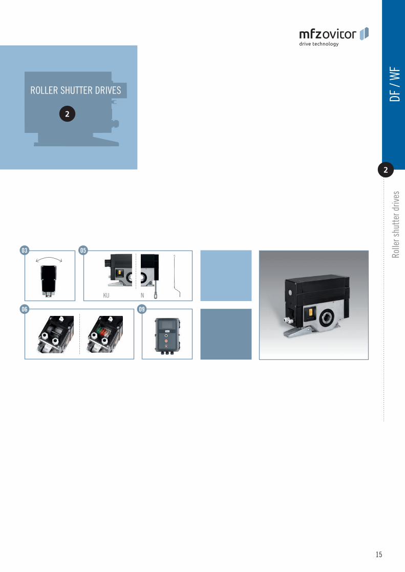
DF / WFDF Three-phase a.c. box slip-on drives for roller shutters and roller grilles with integrated safety catch device WF Single-phase a.c. box slip-on drives for roller shutters and roller grilles with integrated safety catch device
The DF and WF series of MFZ box slip-on drives are characterised by their compact design, facilitating the widest range of installation possibilities. The maintenance-free safety catch device is already integrated and therefore provides the safest solution for the gate. With a complete series from 100 to 400 Nm, MFZ provides the right solution in this category for every on-site situation. We also have the flexibility to quickly realise custom solutions for individual customer requirements at any time.
Compact design
Integrated safety catch device
Self-aligning bearings
Rolled worm shaft
Emergency hand crank (KU) or emergency manual gearing (N) for emergency operation
End position setting via electronic absolute encoder or mechanical limit switch
Thermal protection in the motor windings
Supply 230 / 400V / 50Hz / 3~ or 230 / 50Hz / 1~(custom solutions on request)
Version with external control,for combination with an extensive control programmeSupply: 230 / 400V / 3~, 230V / 1~Frequency: 50 / 60 HzControl voltage: 24V-DC(Section 10 “Controls”)
Custom versions, such as different voltages, frequencies andhollow shaft diameters, on request.
Characteristics
01
03
02
04
05
06
08
09
14
07
DF / WF 30DF / WF 10 DF / WF 40DF / WF 20
10
Rolle
r shu
tter d
rives
2
05
06
DF /
WF
15
2
ROLLER SHUTTER DRIVES
03
KU N
09

Maximum suspended weight in kg
The values in the table take into account 20% safety reserve and a lamella thickness of 25 mm. In certain situations, e.g. for additional door seals or double skin profiles, the friction can be greater and this must be considered when calculating the values.
www.mfz-antriebe.de
DF 10-10-12 129 123 103 89 80 75 67 61 55 50 47DF 20-17-12 219 208 175 151 137 127 114 103 93 86 79DF 30-30-12 386 368 310 266 241 224 201 182 164 151 140DF 40-40-10 515 491 413 355 322 298 267 242 219 202 187
WF 10-7-12 90 86 72 62 56 52 47 42 38 35 33WF 20-12-8 155 147 124 106 97 89 80 73 66 61 56WF 30-20-10 258 245 206 177 161 149 134 121 109 101 93WF 40-25-10 322 307 258 222 201 186 167 151 137 126 117
16
Selecting the right box slip-on drive
SUSPENDED WEIGHTS
To select the optimum drive solution, you will need the diameter of the winding shaft in mm and the suspended weight of the door in kg. With the help of these parameters, the appropriate roller shutter drive can be determined easily and reliably using this table.
133,0
108,0
101,6
159,0
177,8
193,7
244,5
273,0
298,5
323,9
Straightforward drive selection
Diameter Winding shaft Suspended weight
Diameter ((Ø outside) of the winding shaft in mm
219,1
kgØ Drive+ =
DF /
WF
Rolle
r shu
tter d
rives
2

Box slip-on drives for roller shutters and roller grilles with integrated safety catch device
TECHNICAL DATA
DF 20
-17-
12
WF 20
-12-
8
DF 10
-10-
12
WF 10
-7-1
2
DF 40
-40-
10
DF 30
-30-
12
WF 30
-20-
10
WF 40
-25-
10
Drive torque Nm 100 170 300 400 220 150 220 180Drive motor speed min -1 12 12 12 10 12 8 10 10Maximum safety catch torque Nm 669 669 1350 1350 669 669 1350 1350Certificate no. of the safety catch device Door FV 3/007 Door FV 3/008 Door FV 3/007 Door FV 3/008
Motor output kW 0,30 0,55 0,75 1,5 0,30 0,55 0,45 0,45Operating voltage V 230 / 400 / 3~ 230 / 400 / 3~ 230 / 400 / 3~ 230 / 400 / 3~ 230 / 1~ 230 / 1~ 230 / 1~ 230/ 1~
Mains frequency Hz 50 50 50 50 50 50 50 50Control voltage V 24 24 24 24 24 24 24 24Motor current rating A 2,4 / 1,4 4,0 / 2,3 5,5 / 3,2 6,9 / 4,0 5,0 4,8 6,2 6,2Max. cycles per hour * 12 12 12 12 5 5 5 5Fuse protection, on site (mains operation)
A 10 10 10 10 10 10 16 10
IP protection class 54 54 54 54 54 54 54 54 Temperature range ** °C –20 / +60 –20 / +60 –20 / +60 –20 / +60 –20 / +60 –20 / +60 –20 / +60 –20 / +60Continuous sound pressure level dB (A) < 70 < 70 < 70 < 70 < 70 < 70 < 70 < 70Unit weight (approx.) kg 11,5 14 23 25 11,5 14 23 25Maximum output revolutions 12 13 27 27 12 13 27 27 A / height mm 234 250 300 300 234 250 300 300B / width mm 90 111 127 127 90 111 127 127C / length KU / N mm 286 / 318 305 / 318 411 / 379 411 / 379 286 / 318 305 / 318 411 / 379 411 / 379A1 mm 80 80 80 80 80 80 80 80C1 KU / N mm 93 / 125 97 / 130 153 153 93 / 125 97 / 130 153 153Ø - Hollow shaft diameter (standard) mm 30 30 30 40 30 30 30 40
17
* One cycle corresponds to two door movements (opening and closing). The specified values refer to 10 revolutions of the drive shaft per movement and presume an even distribution. ** Temperature range < -20°C: oil grade and electric heating on request.
Detailed drawings with all dimensions are available for download under www.mfz-antriebe.de.
WFDF
DF /
WF
Rol
ler s
hutte
r driv
es
21~ 1~1~ 1~
DF / WF 10 DF / WF 20 DF / WF 30-40
C
A
B C1
A1
C
A
B C1
A1
C
A
B C1
A1
www.mfz-antriebe.de
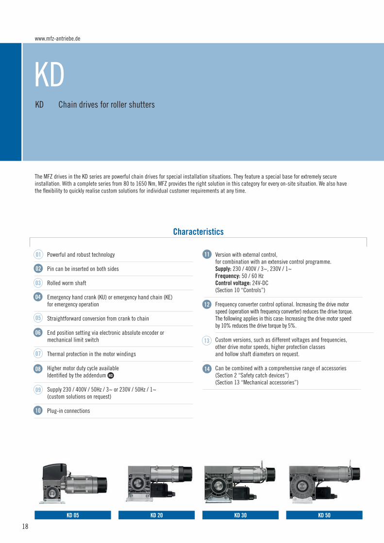
KDKD Chain drives for roller shutters
The MFZ drives in the KD series are powerful chain drives for special installation situations. They feature a special base for extremely secure installation. With a complete series from 80 to 1650 Nm, MFZ provides the right solution in this category for every on-site situation. We also have the flexibility to quickly realise custom solutions for individual customer requirements at any time.
Powerful and robust technology
Pin can be inserted on both sides
Rolled worm shaft
Emergency hand crank (KU) or emergency hand chain (KE) for emergency operation
Straightforward conversion from crank to chain
End position setting via electronic absolute encoder ormechanical limit switch
Thermal protection in the motor windings
Higher motor duty cycle available Identified by the addendum HD
Supply 230 / 400V / 50Hz / 3~ or 230V / 50Hz / 1~(custom solutions on request)
Plug-in connections
Version with external control, for combination with an extensive control programme. Supply: 230 / 400V / 3~, 230V / 1~ Frequency: 50 / 60 HzControl voltage: 24V-DC (Section 10 “Controls”)
Frequency converter control optional. Increasing the drive motor speed (operation with frequency converter) reduces the drive torque.The following applies in this case: Increasing the drive motor speed by 10% reduces the drive torque by 5%.
Custom versions, such as different voltages and frequencies, other drive motor speeds, higher protection classes and hollow shaft diameters on request.
Can be combined with a comprehensive range of accessories(Section 2 “Safety catch devices”)(Section 13 “Mechanical accessories”)
Characteristics
01
09
11
12
14
13
02
03
04
06
05
08
07
10
18
KD 30KD 05 KD 50KD 20

KU KE
04 Rolle
r shu
tter d
rives
3
02
11
08 10
12
06
KD
19
3
ROLLER SHUTTER DRIVES
14
HD
KD 60 KD 70

www.mfz-antriebe.de
2020
Selecting the right slip-on drive
SUSPENDED WEIGHTS
To select the optimum drive solution, you will need the diameter of the winding shaft in mm and the suspended weight of the door in kg. With the help of these parameters, the appropriate roller shutter drive can be determined easily and reliably using this table.The assignment can also be realised using the free MFZ Calculation app.
Maximum suspended weight in kg
The values in the table take into account 20% safety reserve and a lamella thickness of 25 mm. In certain situations, e.g. for additional door seals or double skin profiles, the friction can be greater and this must be considered when calculating the values. A drive with a higher duty cycle (HD) should be chosen for door systems with above-average switching cycles.
Straightforward drive selection
Diameter Winding shaft Suspended weight
kgØ Drive+ =
KDRo
ller s
hutte
r driv
es
3
Gear ratio 1: 1KD 05-7-24 90 86 72 62 56 52 47 42 38 35 33KD 05-13-24 167 159 134 115 105 97 87 79 71 66 61KD 05-13-24 HD 167 159 134 115 105 97 87 79 71 66 61KD 20-22-24 283 270 227 195 177 164 147 133 120 111 103KD 20-22-24 HD 283 270 227 195 177 164 147 133 120 111 103KD 30-30-24 386 368 310 266 241 224 201 182 164 151 140KD 30-30-24 HD 386 368 310 266 241 224 201 182 164 151 140KD 30-40-24 515 491 413 355 322 298 267 242 219 202 187KD 30-40-24 HD 515 491 413 355 322 298 267 242 219 202 187KD 50-75-24 HD 966 920 774 665 603 559 501 454 410 378 351KD 60-100-24 HD 1288 1226 1032 886 804 746 668 605 547 504 467KD 70-125-24 HD 1610 1533 1290 1108 1005 932 835 756 684 630 584KD 70-165-24 HD 2126 2023 1703 1463 1327 1231 1102 999 903 832 771
Gear ratio 2: 1KD 05-7-24 180 172 144 124 112 104 94 84 76 70 66KD 05-13-24 334 318 268 230 210 194 174 158 142 132 122KD 05-13-24 HD 334 318 268 230 210 194 174 158 142 132 122KD 20-22-24 566 540 454 390 354 328 294 266 240 222 206KD 20-22-24 HD 566 540 454 390 354 328 294 266 240 222 206KD 30-30-24 772 736 620 532 482 448 402 364 328 302 280KD 30-30-24 HD 772 736 620 532 482 448 402 364 328 302 280KD 30-40-24 1030 982 826 710 644 596 534 484 438 404 374KD 30-40-24 HD 1030 982 826 710 644 596 534 484 438 404 374KD 50-75-24 HD 1932 1840 1548 1330 1206 1118 1002 908 820 756 702KD 60-100-24 HD 2576 2452 2064 1772 1608 1492 1336 1210 1094 1008 934KD 70-125-24 HD 3220 3066 2580 2360 2010 1864 1670 1512 1368 1260 1168KD 70-165-24 HD 4252 4046 3406 2926 2654 2462 2204 1998 1806 1664 1542
133,0
108,0
101,6
159,0
177,8
193,7
244,5
273,0
298,5
323,9
Diameter (Ø outside) of the winding shaft in mm
219,1
HD
HD
HD
HD
HD
HD
HD
HD
HD
HD
HD
HD
HD
HD
HD
HD

Gear ratio 3: 1KD 05-7-24 270 258 216 186 168 156 141 126 114 105 99KD 05-13-24 501 477 402 345 315 291 261 237 213 198 183KD 05-13-24 HD 501 477 402 345 315 291 261 237 213 198 183KD 20-22-24 849 810 681 585 531 492 441 399 360 333 309KD 20-22-24 HD 849 810 681 585 531 492 441 399 360 333 309KD 30-30-24 1158 1104 930 798 723 672 603 546 492 453 420KD 30-30-24 HD 1158 1104 930 798 723 672 603 546 492 453 420KD 30-40-24 1545 1473 1239 1065 966 894 801 726 657 606 561KD 30-40-24 HD 1545 1473 1239 1065 966 894 801 726 657 606 561KD 50-75-24 HD 2898 2760 2322 1995 1809 1677 1503 1362 1230 1134 1053KD 60-100-24 HD 3864 3678 3096 2658 2412 2238 2004 1815 1641 1512 1401KD 70-125-24 HD 4830 4599 3870 3540 3015 2796 2505 2268 2052 1890 1752KD 70-165-24 HD 6378 6069 5109 4389 3981 3693 3306 2997 2709 2496 2313
Gear ratio 3,8: 1KD 05-7-24 342 327 274 236 213 198 179 160 144 133 125KD 05-13-24 635 604 509 437 399 369 331 300 270 251 232KD 05-13-24 HD 635 604 509 437 399 369 331 300 270 251 232KD 20-22-24 1075 1026 863 741 673 623 559 505 456 422 391KD 20-22-24 HD 1075 1026 863 741 673 623 559 505 456 422 391KD 30-30-24 1467 1398 1178 1011 916 851 764 692 623 574 532KD 30-30-24 HD 1467 1398 1178 1011 916 851 764 692 623 574 532KD 30-40-24 1957 1866 1569 1349 1224 1132 1015 920 832 768 711KD 30-40-24 HD 1957 1866 1569 1349 1224 1132 1015 920 832 768 711KD 50-75-24 HD 3671 3496 2941 2527 2291 2124 1904 1725 1558 1436 1334KD 60-100-24 HD 4894 4659 3922 3367 3055 2835 2538 2299 2079 1915 1775KD 70-125-24 HD 6118 5825 4902 4484 3819 3542 3173 2873 2599 2394 2219KD 70-165-24 HD 8079 7687 6471 5559 5043 4678 4188 3796 3431 3162 2930
Gear ratio 4,5: 1KD 05-7-24 405 387 324 279 252 234 212 189 171 158 149KD 05-13-24 752 716 603 518 473 437 392 356 320 297 275KD 05-13-24 HD 752 716 603 518 473 437 392 356 320 297 275KD 20-22-24 1274 1215 1022 878 797 738 662 599 540 500 464KD 20-22-24 HD 1274 1215 1022 878 797 738 662 599 540 500 464KD 30-30-24 1737 1556 1395 1197 1085 1008 905 819 738 680 630KD 30-30-24 HD 1737 1556 1395 1197 1085 1008 905 819 738 680 630KD 30-40-24 2318 2210 1859 1598 1449 1341 1202 1089 986 909 842KD 30-40-24 HD 2318 2210 1859 1598 1449 1341 1202 1089 986 909 842KD 50-75-24 HD 4347 4140 3483 2993 2714 2516 2255 2043 1845 1701 1580KD 60-100-24 HD 5796 5517 4644 3987 3618 3357 3006 2723 2462 2268 2102KD 70-125-24 HD 7245 6899 5805 5310 4523 4194 3758 3402 3078 2835 2628KD 70-165-24 HD 9567 9104 7664 6584 5972 5540 4959 4496 4064 3744 3470
KD R
olle
r shu
tter d
rives
3
21
133,0
108,0
101,6
159,0
177,8
193,7
244,5
273,0
298,5
323,9
Diameter (Ø outside) of the winding shaft in mm
219,1
HD
HD
HD
HD
HD
HD
HD
HD
HD
HD
HD
HD
HD
HD
HD
HD
HD
HD
HD
HD
HD
HD
HD
HD

www.mfz-antriebe.de
Chain drives for roller shutters
TECHNICAL DATA
Rolle
r shu
tter d
rives
3
Drives with the addendum HD have a higher duty cycle. * One cycle corresponds to two door movements (opening and closing). The specified values refer to 10 revolutions of the drive shaft per movement and presume an even distribution. ** Temperature range < -20°C: oil grade and electric heating on request.
Detailed drawings with all dimensions are available for download under www.mfz-antriebe.de.
HD
KD
Drive torque Nm 70 130 130 220 220Drive motor speed min -1 24 24 24 24 24 Motor output kW 0,55 0,55 0,55 1,1 0,95Operating voltage V 230 / 400 / 3~ 230 / 400 / 3~ 230 / 400 / 3~ 230 / 400 / 3~ 230 / 400 / 3~Mains frequency Hz 50 50 50 50 50Control voltage V 24 24 24 24 24Motor current rating A 3,3 / 1,9 3,0 / 1,7 3,0 / 1,7 4,7 / 2,7 4,1 / 2,4Max. cycles per hour * 20 20 30 20 30Fuse protection, on site (mains operation) A 10 10 10 10 10IP protection class 54 54 54 54 54 Temperature range ** °C –20 / +60 –20 / +60 –20 / +60 –20 / +60 –20 / +60Continuous sound pressure level dB (A) < 70 < 70 < 70 < 70 < 70Unit weight (approx.) kg 16 17 18 22 24Maximum output revolutions 20 20 20 36 36 A / height KU / KE mm 252 / 252 252 / 252 252 / 252 241 / 282 294 / 294B / width KU / KE mm 201 / 251 201 / 251 201 / 251 236 / 252 236 / 252C / length KU / KE mm 422 / 464 422 / 464 438 / 480 452 / 541 433 / 522 A1 mm 62 62 62 122 122C1 mm 80 80 80 80 80Ø - Pin diameter (standard) mm 30 30 30 30 30
HD
KD 20KD 05
KD 05
-13-
24
KD 20
-22-
24 H
D
KD 05
-7-2
4
KD 20
-22-
24
KD 05
-13-
24 H
D
HD
22
KD 05 KD 20 KD 20 HDKD 05 HD
C
A
B C1
A1
C
A
B
A1
C
B
A1
C
A
B C1
A1A
C1 C1

23
Rol
ler s
hutte
r driv
es
3
Drives with the addendum HD have a higher duty cycle. * One cycle corresponds to two door movements (opening and closing). The specified values refer to 10 revolutions of the drive shaft per movement and presume an even distribution. ** Temperature range < -20°C: oil grade and electric heating on request.
Detailed drawings with all dimensions are available for download under www.mfz-antriebe.de.
HD
KD 50KD 30
Drive torque Nm 300 300 400 400 750Drive motor speed min -1 24 24 24 24 24 Motor output kW 1,5 1,2 1,7 1,5 3,0Operating voltage V 230 / 400 / 3~ 230 / 400 / 3~ 230 / 400 / 3~ 230 / 400 / 3~ 230 / 400 / 3~
Mains frequency Hz 50 50 50 50 50Control voltage V 24 24 24 24 24Motor current rating A 8,2 / 4,8 6,3 / 3,6 8,2 / 4,8 6,3 / 3,6 12,1 / 7,0Max. cycles per hour * 20 30 20 30 30Fuse protection, on site (mains operation) A 10 10 10 10 16 / 10IP protection class 54 54 54 54 54 Temperature range ** °C –20 / +60 –20 / +60 –20 / +60 –20 / +60 –20 / +60Continuous sound pressure level dB (A) < 70 < 70 < 70 < 70 < 70Unit weight (approx.) kg 29 34 31 36 48Maximum output revolutions 36 36 36 36 36 A / height KU / KE mm 310 / 310 310 / 310 310 / 310 310 / 310 375 / 375B / width KU / KE mm 248 / 264 248 / 264 248 / 264 248 / 264 271 / 308C / length KU / KE mm 506 / 595 547 / 636 506 / 595 547 / 636 586 / 649A1 mm 120 120 120 120 135C1 mm 100 100 100 100 100Ø - Pin diameter (standard) mm 40 40 40 40 50
KD 30
-30-
24 H
D
KD 50
-75-
24 H
D
KD 30
-30-
24
KD 30
-40-
24 H
D
KD 30
-40-
24
HD HD
KD
HD
KD 30 KD 30 HD KD 50 HD
C
A
B
A1
C
A
B
A1
C
A
B
A1
C1 C1 C1

www.mfz-antriebe.de
24
Chain drives for roller shutters
TECHNICAL DATA
Rolle
r shu
tter d
rives
3
Drives with the addendum HD have a higher duty cycle. * One cycle corresponds to two door movements (opening and closing). The specified values refer to 10 revolutions of the drive shaft per movement and presume an even distribution. ** Temperature range < -20°C: oil grade and electric heating on request.
Detailed drawings with all dimensions are available for download under www.mfz-antriebe.de.
HD
KD
Drive torque Nm 1000 1250 1650Drive motor speed min -1 24 24 24 Motor output kW 4,0 4,0 5,5Operating voltage V 230 / 400 / 3~ 230 / 400 / 3~ 230 / 400 / 3~
Mains frequency Hz 50 50 50Control voltage V 24 24 24Motor current rating A 18,2 / 10,5 18,2 / 10,5 22,8 / 13,2Max. cycles per hour * 30 30 30Fuse protection, on site (mains operation) A 20,0 / 16,0 16,0 / 20,0 16,0 / 25,0IP protection class 54 54 54 Temperature range ** °C –20 / +60 –20 / +60 –20 / +60Continuous sound pressure level dB (A) < 70 < 70 < 70Unit weight (approx.) kg 72 72 81Maximum output revolutions 36 36 36 A / height KU / KE mm 445 / 445 460 / 481 491 / 491B / width KU / KE mm 350 / 350 360 / 360 360 / 360C / length KU / KE mm 678 / 741 716 / 821 735 / 841A1 mm 185 200 200C1 mm 150 150 150Ø - Pin diameter (standard) mm 50 70 70
KD 70KD 60
KD 70
-165
-24 H
D
KD 60
-100
-24 H
D
KD 70
-125
-24 H
D
HDHD HD
KD 60 HD KD 70 HD
C
A
B
A1
C
A
B
A1
C1 C1

25
Rol
ler s
hutte
r driv
es
3
KD

MFZ Antriebe GmbH & Co. KGNeue Mühle 4D-48739 Legden, Germany
www.mfz-antriebe.de 03/
2018
/EN

SERVICE.
DIVERSITY.
QUALITY.
INDIVIDUAL SOLUTIONS.
THIS IS WHAT
DRIVES US.
2018
www.mfz-antriebe.de

SAFETY CATCH DEVICES
www.mfz-antriebe.de

SAFETY CATCH DEVICES
1
External safety catch devices for roller shutter drives Starting on page 28
TS / F
Section on safety catch devices
27

TS / FTS safety catch device, resettable F safety catch device
Two series of safety catch devices are provided to meet the market requirements: series F and series TS. Together they cover the demandsof all on-site situations optimally and comprehensively. Taking into consideration the widest variety of installation options and loading conditions,the two series can always provide the most suitable, size-optimized model. All safety catch devices are fitted with an integrated damping system. It goes without saying that both series have test certificates that are valid throughout Europe.
Different series (TS and F)
Corrosion protection
Compact, individual overall dimensions
With pedestal bearings
Integrated damping
Short drop distance
Safety switch for locking the drive
Maintenance free and wear-free
Housing with main body made of steeland pressure-cast casings (TS series)
Can be reset after being activated (TS series)
Wall bracket (optional), the right solution for all space requirements
Shaft mounting selectable with differentsizes and shapes
Can be combined with chain drives and accessories(Section 1 “Chain drives”)(Section 13 “Mechanical accessories”)
Characteristics
0210
11
12
01
03
06
07
08
05
04
09
13
TS 5, TS 6TSN 0 F 1TS 1/2, TS 2/3, TS 3, TS 4
www.mfz-antriebe.de
28

0702
11 12
TS /
F
F 3, F 5 F 7, F 9
1
SAFETY CATCH DEVICES
29
Saf
ety c
atch
dev
ices
1

30
TSN 0TS 1/2 220 190TS 2/3 290 260 240TS 3 290 260 240 210TS 4 650 560 500 440 400 385 345 310TS 5 1230 1115 1025 920 830 800 745 670 615 570 555TS 6 1685 1525 1480 1370 1235 1130 1045 1030
F 1 F 3F 5 326F 7 1245 1101 965 807 692 640 562 424 401F 9 2837 2480 2207 1861 1625 1521 1363 1107 1008 880
Selecting the right safety catch device
SUSPENDED WEIGHTS
To select the appropriate safety catch device, you will need the diameter of the winding shaft in mm and the armour weight of the gate in kg. With thehelp of these parameters, the appropriate safety catch device can be determined easily and reliably using this table.
Maximum suspended weight in kg
98,0
83,0
76,0
101,6
108,0
133,0
177,8
193,7
219,1
244,5
Straightforward drive selection
Diameter Winding shaft Suspended weight
Diameter (Ø outside) of the winding shaft in mm
TSN 0 311 284 241 232 218 177TS 1/2 460 450 415 375 340 325 290 250TS 2/3 500 455 420 390 355 310TS 3 420 390 355 310TS 4 930 900 800 720TS 5TS 6
F 1 181 165 147 142 135 109F 3 328 280 247F 5 600 541 498 433 374F 7 1803 1584 1392F 9
159,0
kgØ Safety catch device
+ =
323,9
298,5
267,0
368,0
406,4
419,0
508,0
558,8
609,6
622,0
457,2
www.mfz-antriebe.de
TS /
FSa
fety
cat
ch d
evic
es
1

Safety catch devices
TECHNICAL DATA
TSN
0-B
TSN
0-F
TSN
0-A
TSN
0-E
TSN
0-D
TSN
0-C
Permissible torque Nm 145 145 145 145 145 145Maximum safety catch torque Nm 591 591 591 591 591 591Maximum operating speed min -1 22 22 22 22 22 22Test certificate number 240 42140-2
Shaft mounting mm Square, 13 Square, 16 Round with groove, 16
Round with groove, 18
Cloverleaf, 16.8 Square, 18
Bearing type Flange-mounted Flange-mounted Flange-mounted Flange-mounted Flange-mounted Flange-mounted
Unit weight kg 0,9 0,9 0,9 0,9 0,9 0,9
A / height mm 158 158 158 158 158 158B / width mm 25 25 25 25 25 25C / length mm 121 121 121 121 121 121A1 mm 61 61 61 61 61 61C1 mm 61 61 61 61 61 61
31
Detailed drawings with all dimensions are available for download under www.mfz-antriebe.de.
TSN 0
TS /
F S
afet
y cat
ch d
evic
es
1
TSN 0
C
A
B
C1
A1

www.mfz-antriebe.de
32
TS /
F
Safety catch devices
TECHNICAL DATA
TS 2/
3
TS 6
TS 1/
2
TS 5
TS 4
TS 3
Permissible torque Nm 332 542 547 1017 1892 3484Maximum safety catch torque Nm 1313 1869 2058 3509 8230 17768Maximum operating speed min -1 22 22 20 18 12 10Test certificate number Door FV 3 / 012 Door FV 3 / 013 Door FV 3 / 014 Door FV 3 / 015 Door FV 3 / 016 Door FV 3 / 017 Shaft mounting mm Round with groove,
30/35Round with groove,
40Round with groove,
40/50Round with groove,
50Round with groove,
65Round with groove,
80 Bearing type Self-aligning
bearingSelf-aligning
bearingSelf-aligning
bearingSelf-aligning
bearingFixed bearing Fixed bearing
Unit weight kg 4,1 6,6 12,5 21 34,0 68
A / height mm 200 231 253 298 351 414B / width mm 52 57 68 78 94 116C / length mm 210 260 280 340 390 470A1 mm 80 100 118 150 180 220C1 mm 105 130 140 170 195 235
TS
Detailed drawings with all dimensions are available for download under www.mfz-antriebe.de.
Safe
ty c
atch
dev
ices
1
TS 1/2 - 2/3
C
A
C1
A1
TS 3 / TS 4
C
A
C1
A1
TS 5 / TS 6
C
A
C1
A1B BB

Detailed drawings with all dimensions are available for download under www.mfz-antriebe.de.
F 1-B
F 1-F
F 1-A
F 1-E
F 1-D
F 1-C
Permissible torque Nm 79 79 79 79 79 79Maximum safety catch torque Nm 224 224 224 224 224 224Maximum operating speed min -1 20 20 20 20 20 20Test certificate number Door FV 3 / 002 Shaft mounting mm Square, 18 Round with groove,
18Cloverleaf, 16.8 Square, 13 Square, 16 Square, 10
Bearing type Flange-mounted Flange-mounted Flange-mounted Flange-mounted Flange-mounted Flange-mounted
Unit weight kg 0,65 0,65 0,65 0,65 0,65 0,65
A / height mm 140 140 140 140 140 140B / width mm 23 23 23 23 23 23C / length mm 130 130 130 130 130 130A1 mm 65 65 65 65 65 65C1 mm 65 65 65 65 65 65
33
Detailed drawings with all dimensions are available for download under www.mfz-antriebe.de.
F1
TS /
F S
afet
y cat
ch d
evic
es
1
F 1
C
A
C1
A1B

www.mfz-antriebe.de
34
TS /
F
Safety catch devices
TECHNICAL DATA
F 5F 3 F 9F 7
Permissible torque Nm 241 585 1473 3188Maximum safety catch torque Nm 686 1663 6774 18870Maximum operating speed min -1 20 20 12 12Test certificate number Door FV 3 / 003 Door FV 3 / 004 Door FV 3 / 005 Door FV 3 / 006 Shaft mounting mm Round with groove, 30 Round with groove, 40 Round with groove, 50 Round with groove, 80 Bearing type Self-aligning bearing Self-aligning bearing Fixed bearing Fixed bearing
Unit weight kg 2,8 5,0 18,0 36,0
A / height mm 162 205 256 326B / width mm 47 54 46 59C / length mm 210 250 340 440A1 mm 80 105 125 160C1 mm 105 125 170 220
F
Detailed drawings with all dimensions are available for download under www.mfz-antriebe.de.
Safe
ty c
atch
dev
ices
1
F 3 / F 5
C
A
C1
A1
F 7 / F 9
C
A
C1
A1B

Detailed drawings with all dimensions are available for download under www.mfz-antriebe.de.
TS /
F
35
Saf
ety c
atch
dev
ices
1

MFZ Antriebe GmbH & Co. KGNeue Mühle 4D-48739 Legden, Germany
www.mfz-antriebe.de 03/
2018
/EN

SERVICE.
DIVERSITY.
QUALITY.
INDIVIDUAL SOLUTIONS.
THIS IS WHAT
DRIVES US.
2018
www.mfz-antriebe.de

HIGH-SPEED DOOR DRIVES
www.mfz-antriebe.de
HIGH-SPEED DOOR DRIVES
1
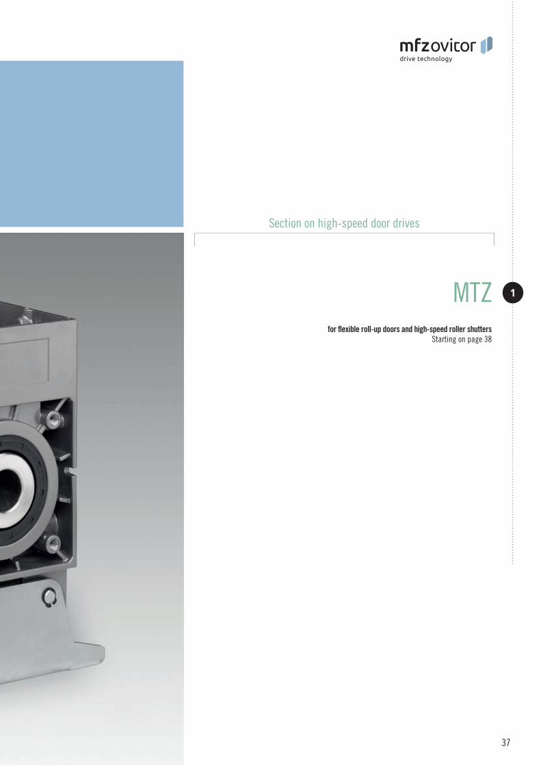
for flexible roll-up doors and high-speed roller shutters Starting on page 38
MTZ
Section on high-speed door drives
37

MTZMTZ-S High-speed door drive for mains operation MTZ-FU High-speed door drive for operation with a frequency converter
The MTZ series of drives provides the optimal solution for light-weight and heavy flexible roll-up doors as well as high-speed roller shutters. They offer a complete programme for this particular application, with model series extend up to 180 rpm and range from 40 to 440 Nm. MFZ high-speed door drives are compact, slip-on drives that are very easy to install on site. A maintenance-free safety catch device is already integrated in the drive and therefore offers the safest option for the door. We also have the flexibility to quickly realise custom solutions for individual customer requirements at any time.
2 versions availableVersion S for mains operationVersion FU for operation with a frequency converter
Integrated safety catch device, independent of position and speed,free of maintenance and wear, integrated damping
Self-aligning bearings
Rolled worm shaft
High holding force via additional magnetic brake
Dimension between centre lines 145 mm or 120 mm (only for MTZ 20 / MTZ 30)
Emergency hand crank for emergency operation (KU)or emergency hand chain (KE)
Straightforward conversion from crank to chain
End position setting viaelectronic absolute encoder ormechanical limit switch
Thermal protection in the motor windings
Higher motor duty cycle available. Identified bythe addendum
Supply 230 / 400V / 50Hz / 3~(custom solutions on request)
Plug-in connections
Version with external control,for combination with an extensive control programmeSupply: 230 / 400V / 3~Frequency: 50 / 60 HzControl voltage: 24V-DC(Section 10 “Controls”)
Frequency converter control optional. Increasing the drive motor speed (operation with frequency converter) reduces the drive torque.The following applies in this case: Increasing the drive motor speed by 10% reduces the drive torque by 5%.
Custom versions, such as different voltages and frequencies, other drive motor speeds, higher protection classes and sleeve shaft diameters, on request.
Characteristics
02
10
1101
07
08
05
04
03
06
09
13
12
15
14
MTZ 05 MTZ 20 MTZ 30 MTZ 50
16
HD
www.mfz-antriebe.de
38

06
11
MTZ
03 07
09
13 14
1
HIGH-SPEED DOOR DRIVES
HD
KU KE
15
39
Hig
h-sp
eed
door
driv
es
1

40
Selecting the appropriate high-speed door drive
SUSPENDED WEIGHTS FLEXIBLE ROLL-UP DOOR
To select the optimum drive solution, you will need the diameter of the winding shaft in mm and the suspended weight of the door in kg. With the help of these parameters, the appropriate high-speed door drive can be determined easily and reliably using this table. This table refers to the flexible roll-up door suspended weight. Corresponding tables for the roller shutter suspended weight are found on the next double page.
108,0
101,6
88,9
114,3
121,0
133,0
177,8
193,7
219,1
244,5
Straightforward drive selection
Diameter Winding shaft Suspended weight
Diameter (Ø outside) of the winding shaft in mm
MTZ-S 05-4-45 69 60 57 54 51 47 40 35 33 29 26MTZ-S 05-4-90 69 60 57 54 51 47 40 35 33 29 26MTZ-S 05-4-115 69 60 57 54 51 47 40 35 33 29 26MTZ-S 05-4-135 69 60 57 54 51 47 40 35 33 29 26
MTZ-S 20-5-135 86 76 72 68 64 59 49 44 41 36 35MTZ-S 20-7-90 120 106 100 95 90 82 69 62 57 51 46MTZ-S 20-7-65 120 106 100 95 90 82 69 62 57 51 46MTZ-S 20-14-45 240 211 200 190 180 164 138 124 114 101 91
MTZ-S 30-10-150 172 151 143 136 128 117 99 89 82 72 65MTZ-S 30-13-120 223 196 186 177 167 153 129 115 106 94 85MTZ-S 30-14-70 240 211 200 190 180 164 138 124 114 101 91MTZ-S 30-14-90 240 211 200 190 180 164 138 124 114 101 91MTZ-S 30-16-45 275 242 229 217 205 188 158 142 130 116 104MTZ-S 30-20-90 343 302 286 272 257 235 198 177 163 145 130
MTZ-S 50-24-105 HD 412 362 343 326 308 282 237 213 196 174 156MTZ-S 50-27-52 HD 464 408 386 367 347 317 267 239 221 219 175MTZ-S 50-44-52 HD 755 664 630 598 565 516 435 390 359 319 286
159,0
kgØ Drive+ =
HD
HD
HD
Maximum suspended weight in kg
The values in the table take into account 20% safety reserve and a sheeting thickness of 6 mm. In certain situations, the friction can be greater and this
must be considered when calculating the values.
The MTZ-S series is not for operation with a frequency converter. The MTZ-FU series may be operated with a frequency converter at max. 87 Hz.
Custom solutions on request.
Drives for mains operation
!
www.mfz-antriebe.de
MTZ
High
-spe
ed d
oor d
rives
1

The values in the table take into account 20% safety reserve and a sheeting thickness of 6 mm. In certain situations, the friction can be greater and this
must be considered when calculating the values.
The MTZ-S series is not for operation with a frequency converter. The MTZ-FU series may be operated with a frequency converter at max. 87 Hz.
Custom solutions on request.
108,0
101,6
88,9
114,3
121,0
133,0
177,8
193,7
219,1
244,5
Diameter (Ø outside) of the winding shaft in mm
50 Hz (87 Hz)MTZ-FU 05-4-135 69 (48) 60 (42) 57 (40) 54 (38) 51 (36) 47 (33) 40 (28) 35 (24) 33 (23) 29 (20) 26 (18)MTZ-FU 05-4-180 69 (48) 60 (42) 57 (40) 54 (38) 51 (36) 47 (33) 40 (28) 35 (24) 33 (23) 29 (20) 26 (18)MTZ-FU 05-6-180 103 (72) 91 (64) 86 (60) 82 (57) 77 (54) 70 (49) 59 (41) 53 (37) 49 (34) 43 (30) 39 (27)MTZ-FU 05-7-75 120 (84) 106 (74) 100 (70) 95 (67) 90 (63) 82 (57) 69 (48) 62 (43) 57 (40) 51 (35) 46 (32)MTZ-FU 05-7-90 120 (84) 106 (74) 100 (70) 95 (67) 90 (63) 82 (57) 69 (48) 62 (43) 57 (40) 51 (35) 46 (32)MTZ-FU 05-10-45 172 (120) 151 (106) 143 (100) 136 (95) 128 (89) 117 (82) 99 (69) 89 (62) 82 (57) 72 (50) 65 (45)
MTZ-FU 20-9-70 155 (109) 136 (95) 129 (90) 122 (85) 116 (81) 106 (74) 89 (62) 80 (56) 73 (51) 65 (45) 58 (40)MTZ-FU 20-9-90 155 (109) 136 (95) 129 (90) 122 (85) 116 (81) 106 (74) 89 (62) 80 (56) 73 (51) 65 (45) 58 (40)MTZ-FU 20-9-135 155 (109) 136 (95) 129 (90) 122 (85) 116 (81) 106 (74) 89 (62) 80 (56) 73 (51) 65 (45) 58 (40)MTZ-FU 20-14-45 240 (168) 211 (148) 200 (140) 190 (133) 180 (126) 164 (114) 138 (96) 124 (86) 114 (79) 101 (70) 91 (63)
MTZ-FU 30-10-150 172 (120) 151 (106) 143 (100) 136 (95) 128 (89) 117 (82) 99 (69) 89 (62) 82 (57) 72 (50) 65 (45)MTZ-FU 30-10-180 172 (120) 151 (106) 143 (100) 136 (95) 128 (89) 117 (82) 99 (69) 89 (62) 82 (57) 72 (50) 65 (45)MTZ-FU 30-13-60 223 (156) 196 (137) 186 (130) 177 (124) 167 (116) 153 (107) 129 (90) 115 (80) 106 (74) 94 (65) 85 (59)MTZ-FU 30-13-90 223 (156) 196 (137) 186 (130) 177 (124) 167 (116) 153 (107) 129 (90) 115 (80) 106 (74) 94 (65) 85 (59)MTZ-FU 30-15-150 HD 258 (180) 227 (159) 215 (150) 204 (143) 193 (135) 176 (123) 148 (103) 133 (93) 122 (85) 109 (76) 97 (68)MTZ-FU 30-16-180 HD 275 (192) 242 (169) 229 (160) 217 (152) 205 (143) 188 (131) 158 (110) 142 (99) 130 (91) 116 (81) 104 (72)MTZ-FU 30-18-60 309 (216) 272 (190) 258 (180) 245 (172) 231 (161) 211 (147) 178 (124) 160 (112) 147 (102) 130 (91) 117 (82)MTZ-FU 30-18-120 309 (216) 272 (190) 258 (180) 245 (172) 231 (161) 211 (147) 178 (124) 160 (112) 147 (102) 130 (91) 117 (82)MTZ-FU 30-20-90 343 (240) 302 (211) 286 (200) 272 (190) 257 (179) 235 (164) 198 (138) 177 (124) 163 (114) 145 (101) 130 (91)MTZ-FU 30-25-90 HD 429 (300) 378 (264) 358 (250) 340 (238) 321 (224) 293 (205) 247 (172) 222 (155) 204 (142) 181 (126) 162 (113)MTZ-FU 30-32-60 549 (384) 483 (338) 458 (320) 435 (304) 411 (287) 375 (262) 316 (221) 284 (199) 261 (182) 232 (162) 208 (145)MTZ-FU 30-33-45 567 (397) 498 (349) 472 (330) 449 (314) 424 (296) 387 (270) 326 (228) 293 (205) 270 (189) 239 (167) 214 (149)
MTZ-FU 50-29-105 HD 498 (348) 438 (307) 415 (290) 394 (276) 372 (260) 340 (238) 287 (200) 257 (179) 236 (165) 210 (147) 188 (131)MTZ-FU 50-33-105 HD 567 (397) 498 (349) 472 (330) 449 (314) 424 (296) 387 (270) 326 (228) 293 (205) 270 (189) 239 (167) 214 (149)MTZ-FU 50-44-52 HD 755 (528 ) 664 (465) 630 (441) 598 (418) 565 (395) 516 (361) 435 (304) 390 (273) 359 (251) 319 (223) 286 (200)
159,0
Maximum suspended weight in kg
HD
HD
HD
HD
HD
HD
Drives for frequency converter operation Nominal frequency 50 Hz
!
41
MTZ
Hig
h-sp
eed
door
driv
es
1

42
Selecting the appropriate high-speed door drive
SUSPENDED WEIGHTS ROLLER SHUTTER
To select the optimum drive solution, you will need the diameter of the winding shaft in mm and the suspended weight of the door in kg. With the help of these parameters, the appropriate high-speed door drive can be determined easily and reliably using this table. This table refers to the roller shutter suspended weight. Corresponding tables for the flexible roll-up door suspended weight are found on the previous double page.
108,0
101,6
88,9
114,3
121,0
133,0
177,8
193,7
219,1
244,5
Straightforward drive selection
Diameter Winding shaft Suspended weight
Diameter (Ø outside) of the winding shaft in mm
MTZ-S 05-4-45 57 51 49 47 45 41 35 32 30 27 24MTZ-S 05-4-90 57 51 49 47 45 41 35 32 30 27 24MTZ-S 05-4-115 57 51 49 47 45 41 35 32 30 27 24MTZ-S 05-4-135 57 51 49 47 45 41 35 32 30 27 24
MTZ-S 20-5-135 72 64 61 59 56 52 44 40 37 33 30MTZ-S 20-7-90 100 90 86 82 78 72 62 56 52 47 42MTZ-S 20-7-65 100 90 86 82 78 72 62 56 52 47 42MTZ-S 20-14-45 200 180 172 164 156 144 124 112 104 94 84
MTZ-S 30-10-150 143 129 123 117 112 103 89 80 75 67 61MTZ-S 30-13-120 186 167 159 152 145 134 115 105 97 87 79MTZ-S 30-14-70 200 180 172 164 156 144 124 112 104 94 84MTZ-S 30-14-90 200 180 172 164 156 144 124 112 104 94 84MTZ-S 30-16-45 229 206 196 187 179 165 142 129 119 107 97MTZ-S 30-20-90 286 258 245 234 223 206 177 161 149 134 121
MTZ-S 50-24-105 HD 344 309 294 281 268 248 213 193 179 160 145MTZ-S 50-27-52 HD 387 348 331 316 302 279 239 217 201 180 163MTZ-S 50-44-52 HD 630 567 540 515 492 454 390 354 328 294 266
159,0
kgØ Drive+ =
HD
HD
HD
Maximum suspended weight in kg
The values in the table take into account 20% safety reserve and a sheeting thickness of 25 mm. In certain situations, e.g. for additional door seals or double skin
profiles, the friction can be greater and this must be considered when calculating the values.
The MTZ-S series is not for operation with a frequency converter. The MTZ-FU series may be operated with a frequency converter at max. 87 Hz.
Custom solutions on request.
Drives for mains operation
!
www.mfz-antriebe.de
MTZ
High
-spe
ed d
oor d
rives
1

The values in the table take into account 20% safety reserve and a sheeting thickness of 25 mm. In certain situations, e.g. for additional door seals or double skin
profiles, the friction can be greater and this must be considered when calculating the values.
The MTZ-S series is not for operation with a frequency converter. The MTZ-FU series may be operated with a frequency converter at max. 87 Hz.
Custom solutions on request.
108,0
101,6
88,9
114,3
121,0
133,0
177,8
193,7
219,1
244,5
Diameter (Ø outside) of the winding shaft in mm
50 Hz (87 Hz)MTZ-FU 05-4-135 57 (39) 51 (35) 49 (34) 47 (33) 45 (32) 41 (29) 35 (25) 32 (22) 30 (21) 27 (19) 24 (17)MTZ-FU 05-4-180 57 (39) 51 (35) 49 (34) 47 (33) 45 (32) 41 (29) 35 (25) 32 (22) 30 (21) 27 (19) 24 (17)MTZ-FU 05-6-180 86 (60) 77 (53) 74 (52) 70 (49) 67 (47) 62 (43) 53 (37) 48 (34) 45 (32) 40 (28) 36 (25)MTZ-FU 05-7-75 100 (70) 90 (63) 86 (60) 82 (57) 78 (55) 72 (50) 62 (43) 56 (39) 52 (36) 47 (33) 42 (29)MTZ-FU 05-7-90 100 (70) 90 (63) 86 (60) 82 (57) 78 (55) 72 (50) 62 (43) 56 (39) 52 (36) 47 (33) 42 (29)MTZ-FU 05-10-45 143 (100) 129 (90) 123 (86) 117 (82) 112 (78) 103 (72) 89 (62) 80 (56) 75 (53) 67 (47) 61 (43)
MTZ-FU 20-9-70 129 (90) 116 (81) 110 (77) 105 (74) 101 (71) 93 (65) 80 (56) 72 (50) 67 (47) 60 (42) 54 (38)MTZ-FU 20-9-90 129 (90) 116 (81) 110 (77) 105 (74) 101 (71) 93 (65) 80 (56) 72 (50) 67 (47) 60 (42) 54 (38)MTZ-FU 20-9-135 129 (90) 116 (81) 110 (77) 105 (74) 101 (71) 93 (65) 80 (56) 72 (50) 67 (47) 60 (42) 54 (38)MTZ-FU 20-14-45 200 (140) 180 (126) 172 (120) 164 (115) 156 (109) 144 (101) 124 (87) 112 (78) 104 (73) 94 (66) 84 (59)
MTZ-FU 30-10-150 143 (100) 129 (90) 123 (86) 117 (82) 112 (78) 103 (72) 89 (62) 80 (56) 75 (53) 67 (47) 61 (43)MTZ-FU 30-10-180 143 (100) 129 (90) 123 (86) 117 (82) 112 (78) 103 (72) 89 (62) 80 (56) 75 (53) 67 (47) 61 (43)MTZ-FU 30-13-60 186 (130) 167 (116) 159 (111) 152 (106) 145 (102) 134 (94) 115 (81) 105 (74) 97 (68) 87 (61) 79 (55)MTZ-FU 30-13-90 186 (130) 167 (116) 159 (111) 152 (106) 145 (102) 134 (94) 115 (81) 105 (74) 97 (68) 87 (61) 79 (55)MTZ-FU 30-15-150 HD 215 (150) 193 (135) 184 (129) 176 (123) 168 (118) 155 (109) 133 (93) 121 (85) 112 (78) 100 (70) 91 (64)MTZ-FU 30-16-180 HD 229 (160) 206 (144) 196 (137) 187 (131) 179 (125) 165 (116) 142 (99) 129 (90) 119 (83) 107 (75) 97 (68)MTZ-FU 30-18-60 258 (180) 232 (162) 221 (155) 211 (148) 201 (141) 186 (130) 160 (112) 145 (102) 134 (94) 120 (84) 109 (76)MTZ-FU 30-18-120 258 (180) 232 (162) 221 (155) 211 (148) 201 (141) 186 (130) 160 (112) 145 (102) 134 (94) 120 (84) 109 (76)MTZ-FU 30-20-90 286 (200) 258 (180) 245 (172) 234 (164) 223 (156) 206 (144) 177 (124) 161 (113) 149 (104) 134 (94) 121 (85)MTZ-FU 30-25-90 HD 358 (250) 322 (225) 307 (215) 293 (205) 279 (195) 258 (181) 222 (155) 201 (141) 186 (130) 167 (117) 151 (106)MTZ-FU 30-32-60 458 (320) 412 (288) 392 (274) 375 (263) 357 (250) 330 (231) 284 (199) 257 (180) 239 (167) 214 (150) 194 (136)MTZ-FU 30-33-45 473 (331) 425 (297) 405 (284) 386 (270) 369 (258) 341 (239) 293 (205) 265 (186) 246 (172) 220 (154) 200 (140)
MTZ-FU 50-29-105 HD 415 (290) 374 (261) 356 (249) 340 (238) 324 (227) 299 (209) 257 (180) 233 (163) 216 (151) 194 (136) 176 (123)MTZ-FU 50-33-105 HD 473 (331) 425 (297) 405 (284) 386 (270) 369 (258) 341 (239) 293 (205) 265 (186) 246 (172) 220 (154) 200 (140)MTZ-FU 50-44-52 HD 630 (441) 567 (396) 540 (378) 515 (361) 492 (344) 454 (318) 390 (273) 354 (248) 328 (230) 294 (206) 266 (186)
159,0
Maximum suspended weight in kg
HD
HD
HD
HD
HD
HD
Drives for frequency converter operation Nominal frequency 50 Hz
!
43
MTZ
Hig
h-sp
eed
door
driv
es
1

MTZ-
S 05-
4-90
MTZ-
S 20-
7-65
MTZ-
S 05-
4-45
MTZ-
S 20-
14-4
5
MTZ-
S 05-
4-13
5
MTZ-
S 05-
4-11
5
MTZ-
S 20-
7-90
MTZ-
S 20-
5-13
5
Drive torque Nm 40 40 40 40 140 70 70 50Drive motor speed min -1 45 90 115 135 45 65 90 135Maximum safety catch torque Nm 309 309 309 258 784 784 784 784Certificate no. of the safety catch device Door FV 6 / 092 Door FV 6 / 092 / 1 Door FV 9 / 147 / 1 Motor output kW 0,55 0,55 0,75 0,55 1,1 0,75 0,75 1,1Operating voltage V 230 / 400 / 3~ 230 / 400 / 3~ 230 / 400 / 3~ 230 / 400 / 3~ 230 / 400 / 3~ 230 / 400 / 3~ 230 / 400 / 3~ 230 / 400 / 3~
Mains frequency Hz 50 50 50 50 50 50 50 50Control voltage V 24 24 24 24 24 24 24 24Motor current rating A 2,1 / 1,2 2,1 / 1,2 3,3 / 1,9 2,1 / 1,2 5,0 / 2,9 3,5 / 2,0 3,1 / 1,8 4,4 / 2,5Max. cycles per hour * 20 45 45 45 20 30 45 45Fuse protection, on site (mains operation)
A 10,0 10,0 10,0 10,0 10,0 10,0 10,0 10,0
IP protection class 54 54 54 54 54 54 54 54 Temperature range ** °C –20 / +60 –20 / +60 –20 / +60 –20 / +60 –20 / +60 –20 / +60 –20 / +60 –20 / +60Continuous sound pressure level dB (A) < 70 < 70 < 70 < 70 < 70 < 70 < 70 < 70Unit weight (approx.) kg 19 19 19 19 33 27 30 30Maximum output revolutions 13 13 13 13 18 18 18 18 A / height KU / KE mm 290 / 290 290 / 290 290 / 290 290 / 290 318 / 318 318 / 318 318 / 318 318 / 318B / width KU / KE mm 111 / 191 111 / 191 111 / 191 111 / 191 122 / 191 122 / 191 122 / 191 122 / 191C / length KU / KE mm 409 / 498 409 / 498 425 / 514 409 / 498 480 / 569 461 / 550 461 / 550 461 / 550 A1 mm 100 100 100 100 145 145 145 145C1 mm 85 85 85 85 110 110 110 110Ø - Possible sleeve shaft diameter mm 25 / 25,4 / 30 25 / 25,4 / 30
MTZ-S 20MTZ-S 05
Drives with the addendum HD have a higher duty cycle. * One cycle corresponds to two door movements (opening and closing). The specified values refer to 10 revolutions of the drive shaft per movement and presume an even distribution. ** Temperature range < -20°C: oil grade and electric heating on request.
Detailed drawings with all dimensions are available for download under www.mfz-antriebe.de.
HD
www.mfz-antriebe.de
44
MTZ MTZ-S high-speed door drives for mains operation
TECHNICAL DATA
High
-spe
ed d
oor d
rives
1
MTZ-S 20
C
A
C1
A1
B
MTZ-S 05
C
A
C1
A1
B

HD
45
MTZ
Hig
h-sp
eed
door
driv
es
1MT
Z-S 3
0-14
-70
MTZ-
S 30-
10-1
50
MTZ-
S 30-
16-4
5
MTZ-
S 30-
13-1
20
MTZ-
S 30-
20-9
0
MTZ-
S 30-
14-9
0
MTZ-
S 50-
27-5
2 HD
MTZ-
S 50-
24-1
25 H
D
Drive torque Nm 160 140 140 200 130 100 270 240Drive motor speed min -1 45 70 90 90 120 150 52 105Maximum safety catch torque Nm 2680 2680 2680 2680 2680 2680 4030 4030Certificate no. of the safety catch device 24042140-1 Door FV 6 / 099
Motor output kW 1,1 1,5 1,5 2,2 2,2 2,2 2,2 3,0Operating voltage V 230 / 400 / 3~ 230 / 400 / 3~ 230 / 400 / 3~ 230 / 400 / 3~ 230 / 400 / 3~ 230 / 400 / 3~ 230 / 400 / 3~ 230 / 400 / 3~
Mains frequency Hz 50 50 50 50 50 50 50 50Control voltage V 24 24 24 24 24 24 24 24Motor current rating A 7,9 / 4,6 8,8 / 5,1 7,9 / 4,6 7,9 / 4,6 8,8 / 5,1 8,8 / 5,1 8,8 / 5,1 12,5 / 7,2Max. cycles per hour * 20 45 45 45 45 45 30 45Fuse protection, on site (mains operation)
A 10,0 10,0 10,0 10,0 10,0 10,0 10,0 16 / 10,0
IP protection class 54 54 54 54 54 54 54 54 Temperature range ** °C –20 / +60 –20 / +60 –20 / +60 –20 / +60 –20 / +60 –20 / +60 –20 / +60 –20 / +60Continuous sound pressure level dB (A) < 70 < 70 < 70 < 70 < 70 < 70 < 70 < 70Unit weight (approx.) kg 30 30 30 30 32 32 43 45Maximum output revolutions 18 18 18 18 18 18 36 36 A / height KU / KE mm 335 / 335 335 / 335 335 / 335 335 / 335 335 / 335 335 / 335 375 / 375 375 / 375B / width KU / KE mm 122 / 191 122 / 191 122 / 191 122 / 191 122 / 191 122 / 191 174 / 202 174 / 221C / length KU / KE mm 516 / 605 516 / 605 516 / 605 516 / 605 516 / 605 516 / 605 614 / 703 614 / 617 A1 mm 145 145 145 145 145 145 135 135C1 mm 130 130 130 130 130 130 130 130Ø - Possible sleeve shaft diameter mm 25 / 25,4 / 30 / 40 50 50
MTZ-S 50MTZ-S 30
Drives with the addendum HD have a higher duty cycle. * One cycle corresponds to two door movements (opening and closing). The specified values refer to 10 revolutions of the drive shaft per movement and presume an even distribution. ** Temperature range < -20°C: oil grade and electric heating on request.
Detailed drawings with all dimensions are available for download under www.mfz-antriebe.de.
MTZ-S 30
C
C1
A1
MTZ-S 50 HD
C
A
C1
A1
BB
A
HD HD

MTZ-
FU 05
-7-7
5
MTZ-
FU 05
-6-1
80
MTZ-
FU 05
-10-
45 H
D
MTZ-
FU 05
-4-1
80
MTZ-
FU 05
-4-1
35
MTZ-
FU 05
-7-9
0
Drive torque (50 Hz / 87 Hz) Nm 100 / 70 70 / 49 70 / 49 40 / 28 40 / 28 60 / 42Drive motor speed (50 Hz / 87 Hz) min -1 45 / 78 75 / 130 90 / 156 135 / 235 180 / 313 180 / 313Maximum safety catch torque Nm 309 269 269 258 258 258Certificate no. of the safety catch device Door FV 6 / 092 Door FV 6 / 092 / 1
Motor output kW 0,75 0,75 0,75 0,75 1,1 1,5Operating voltage V 230 / 3~ 230 / 3~ 230 / 3~ 230 / 3~ 230 / 3~ 400 / 3~ 400 / 3~
Mains frequency Hz 50 50 50 50 50 50Control voltage V 24 24 24 24 24 24Motor current rating A 4,1 4,1 4,1 4,1 4,5 2,6 4,6Max. cycles per hour * 30 45 45 45 45 45IP protection class 54 54 54 54 54 54 Temperature range ** °C –20 / +60 –20 / +60 –20 / +60 –20 / +60 –20 / +60 –20 / +60Continuous sound pressure level dB (A) < 70 < 70 < 70 < 70 < 70 < 70Unit weight (approx.) kg 19 19 19 19 19 19Maximum output revolutions 13 13 13 13 13 13 Operation with CS310 FU (frequency converter)
kW V
0,75 230 / 1~
0,75 230 / 1~
0,75 230 / 1~
0,75 230 / 1~
0,75 230 / 1~
0,75 400/ 3~
2,2 400 / 3~
Fuse protection, on site (frequency converter operation)
A 10,0 10,0 10,0 10,0 20,0 10,0 10,0
Efficiency factor cos φ 0,68 0,68 0,68 0,68 0,82 0,75
A / height KU / KE mm 290 / 290 290 / 290 290 / 290 290 / 290 290 / 290 290 / 290B / width KU / KE mm 108 / 190 108 / 190 108 / 190 108 / 190 108 / 190 108 / 190C / length KU / KE mm 461 / 549 461 / 549 461 / 549 461 / 549 461 / 549 461 / 549A1 mm 100 100 100 100 100 100C1 mm 85 85 85 85 85 85Ø - Possible sleeve shaft diameter mm 25 / 25,4 / 30
MTZ-FU 05
Drives with the addendum HD have a higher duty cycle. * One cycle corresponds to two door movements (opening and closing). The specified values refer to 10 revolutions of the drive shaft per movement and presume an even distribution. ** Temperature range < -20°C: oil grade and electric heating on request.
Detailed drawings with all dimensions are available for download under www.mfz-antriebe.de.
HD
www.mfz-antriebe.de
46
MTZ MTZ-FU high-speed door drives for frequency converter operation
TECHNICAL DATA
High
-spe
ed d
oor d
rives
1 HD
MTZ-FU 05MTZ-FU 05 HD
C
A
C1
A1
B
A
B
A1
C1
C
47
MTZ
Hig
h-sp
eed
door
driv
es
1
MTZ-
FU 20
-9-7
0
MTZ-
FU 20
-9-1
35
MTZ-
FU 20
-14-
45
MTZ-
FU 20
-9-9
0
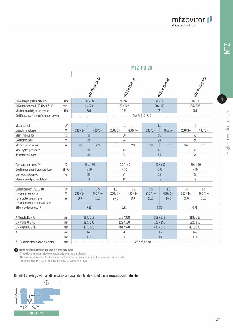
Drive torque (50 Hz / 87 Hz) Nm 140 / 98 90 / 63 90 / 63 90 / 63Drive motor speed (50 Hz / 87 Hz) min -1 45 / 78 70 / 122 90 / 156 135 / 235Maximum safety catch torque Nm 784 784 784 784Certificate no. of the safety catch device Door FV 9 / 147 / 1
Motor output kW 1,1 1,1 1,1 1,5Operating voltage V 230 / 3~ 400 / 3~ 230 / 3~ 400 / 3~ 230 / 3~ 400 / 3~ 230 / 3~ 400 / 3~Mains frequency Hz 50 50 50 50Control voltage V 24 24 24 24Motor current rating A 5,0 2,9 5,0 2,9 5,0 2,9 5,6 3,3Max. cycles per hour * 20 45 45 45IP protection class 54 54 54 54 Temperature range ** °C –20 / +60 –20 / +60 –20 / +60 –20 / +60Continuous sound pressure level dB (A) < 70 < 70 < 70 < 70Unit weight (approx.) kg 23 23 23 23Maximum output revolutions 18 18 18 18 Operation with CS310 FU (frequency converter)
kW V
1,5 230 / 1~
1,5 400 / 3~
1,5 230 / 1~
1,5 400 / 3~
1,5 230 / 1~
1,5 400 / 3~
1,5 230 / 1~
1,5 400 / 3~
Fuse protection, on site (frequency converter operation)
A 20,0 10,0 20,0 10,0 20,0 10,0 20,0 10,0
Efficiency factor cos φ 0,81 0,81 0,81 0,71
A / height KU / KE mm 318 / 318 318 / 318 318 / 318 318 / 318B / width KU / KE mm 122 / 190 122 / 190 122 / 190 122 / 190C / length KU / KE mm 481 / 570 481 / 570 481 / 570 481 / 570A1 mm 145 145 145 145C1 mm 110 110 110 110Ø - Possible sleeve shaft diameter mm 25 / 25,4 / 30
MTZ-FU 20
Drives with the addendum HD have a higher duty cycle. * One cycle corresponds to two door movements (opening and closing). The specified values refer to 10 revolutions of the drive shaft per movement and presume an even distribution. ** Temperature range < -20°C: oil grade and electric heating on request.
Detailed drawings with all dimensions are available for download under www.mfz-antriebe.de.
HD
MTZ-FU 20
C
A
C1
A1
B

Drives with the addendum HD have a higher duty cycle. * One cycle corresponds to two door movements (opening and closing). The specified values refer to 10 revolutions of the drive shaft per movement and presume an even distribution. ** Temperature range < -20°C: oil grade and electric heating on request.
Detailed drawings with all dimensions are available for download under www.mfz-antriebe.de.
HD
www.mfz-antriebe.de
Drive torque (50 Hz / 87 Hz) Nm 330 / 231 130 / 91 180 / 126 320 / 224 130 / 91Drive motor speed (50 Hz / 87 Hz) min -1 45 / 78 60 / 104 60 / 104 60 / 104 90 / 156Maximum safety catch torque Nm 2680 2680 2680 2680 2680Certificate no. of the safety catch device 24042140-1
Motor output kW 2,2 1,1 1,1 2,2 1,5Operating voltage V 400 / 3~ 230 / 3~ 400 / 3~ 230 / 3~ 400 / 3~ 400 / 3~ 230 / 3~ 400 / 3~
Mains frequency Hz 50 50 50 50 50Control voltage V 24 24 24 24 24Motor current rating A 6,5 5,6 3,3 7,3 4,2 6,5 7,3 4,2Max. cycles per hour * 20 30 30 30 45IP protection class 54 54 54 54 54 Temperature range ** °C –20 / +60 –20 / +60 –20 / +60 –20 / +60 –20 / +60Continuous sound pressure level dB (A) < 70 < 70 < 70 < 70 < 70Unit weight (approx.) kg 32 30 30 32 30Maximum output revolutions 18 18 18 18 18 Operation with CS310 FU (frequency converter)
kW V
3,0 400 / 3~
1,5 230 / 1~
1,5 400 / 3~
1,5 230 / 3~
2,2 400 / 3~
3,0 400 / 3~
1,5 230 / 3~
2,2 400 / 3~
Fuse protection, on site (frequency converter operation)
A 10,0 20,0 10,0 20,0 10,0 10,0 20,0 10,0
Efficiency factor cos φ 0,7 0,71 0,77 0,7 0,77
A / height KU / KE mm 335 / 335 335 / 335 335 / 335 335 / 335 335 / 335B / width KU / KE mm 122 / 190 122 / 190 122 / 190 122 / 190 122 / 190C / length KU / KE mm 556 / 619 556 / 604 536 / 599 556 / 619 536 / 599A1 mm 145 145 145 145 145C1 mm 130 130 130 130 130Ø - Possible sleeve shaft diameter mm 25 / 25,4 / 30 / 40
48
MTZ MTZ-FU high-speed door drives for frequency converter operation
TECHNICAL DATA
High
-spe
ed d
oor d
rives
1 MTZ-
FU 30
-13-
60
MTZ-
FU 30
-13-
90
MTZ-
FU 30
-33-
45
MTZ-
FU 30
-18-
60
MTZ-FU 30
MTZ-
FU 30
-32-
60
MTZ-FU 30
C
C1
A1
B
A

Drives with the addendum HD have a higher duty cycle. * One cycle corresponds to two door movements (opening and closing). The specified values refer to 10 revolutions of the drive shaft per movement and presume an even distribution. ** Temperature range < -20°C: oil grade and electric heating on request.
Detailed drawings with all dimensions are available for download under www.mfz-antriebe.de.
MTZ-
FU 30
-25-
90 H
D
MTZ-
FU 30
-10-
180
MTZ-
FU 30
-20-
90
MTZ-
FU 30
-15-
150 H
D
MTZ-
FU 30
-10-
150
MTZ-
FU 30
-18-
120
Drive torque (50 Hz / 87 Hz) Nm 200 / 140 250 / 182 180 / 126 100 / 70 150 / 105 100 / 70 160 / 112Drive motor speed (50 Hz / 87 Hz) min -1 90 / 156 90 / 156 120 / 209 150 / 261 150 / 261 180 / 313 180 / 313Maximum safety catch torque Nm 2680 2680 2680 2680 2680 2680 2680Certificate no. of the safety catch device 24042140-1
Motor output kW 2,2 3,0 3,0 2,2 4,0 2,2 4,0Operating voltage V 400 / 3~ 400 / 3~ 400 / 3~ 400 / 3~ 400 / 3~ 400 / 3~ 400 / 3~
Mains frequency Hz 50 50 50 50 50 50 50Control voltage V 24 24 24 24 24 24 24Motor current rating A 6,5 7,0 7,0 5,1 8,8 5,1 8,8Max. cycles per hour * 45 45 45 45 60 45 60IP protection class 54 54 54 54 54 54 54 Temperature range ** °C –20 / +60 –20 / +60 –20 / +60 –20 / +60 –20 / +60 –20 / +60 –20 / +60Continuous sound pressure level dB (A) < 70 < 70 < 70 < 70 < 70 < 70 < 70Unit weight (approx.) kg 32 37 37 32 37 32 41Maximum output revolutions 18 18 18 18 18 18 18 Operation with CS310 FU (frequency converter)
kW V
3,0 400 / 3~
3,0 400 / 3~
3,0 400 / 3~
2,2 400 / 3~
4,0 400 / 3~
2,2 400 / 3~
4,0 400 / 3~
Fuse protection, on site (frequency converter operation)
A 10,0 10,0 10,0 10,0 16,0 10,0 16,0
Efficiency factor cos φ 0,7 0,8 0,82 0,73 0,83 0,73 0,83
A / height KU / KE mm 335 / 335 370 / 370 335 / 335 335 / 335 335 / 335 335 / 335 370 / 370B / width KU / KE mm 122 / 190 174 / 214 122 / 190 122 / 190 122 / 190 122 / 190 174 / 214C / length KU / KE mm 556 / 619 593 / 656 536 / 599 516 / 605 536 / 599 536 / 599 593 / 656A1 mm 145 145 145 145 145 145 145C1 mm 130 130 130 130 130 130 130Ø - Possible sleeve shaft diameter mm 25 / 25,4 / 30
MTZ-FU 30
MTZ-
FU 30
-16-
180 H
D
49
MTZ
Hig
h-sp
eed
door
driv
es
1
Drives with the addendum HD have a higher duty cycle. * One cycle corresponds to two door movements (opening and closing). The specified values refer to 10 revolutions of the drive shaft per movement and presume an even distribution. ** Temperature range < -20°C: oil grade and electric heating on request.
Detailed drawings with all dimensions are available for download under www.mfz-antriebe.de.
HD
HD HD HD
MTZ-FU 30
C
C1
A1
B
A
MTZ-FU 30 HD
C
C1
A1
B
A
Drives with the addendum HD have a higher duty cycle. * One cycle corresponds to two door movements (opening and closing). The specified values refer to 10 revolutions of the drive shaft per movement and presume an even distribution. ** Temperature range < -20°C: oil grade and electric heating on request.
Detailed drawings with all dimensions are available for download under www.mfz-antriebe.de.
HD
MTZ-
FU 50
-29-
105 H
D
MTZ-
FU 50
-44-
52 H
D
MTZ-
FU 50
-33-
105 H
D
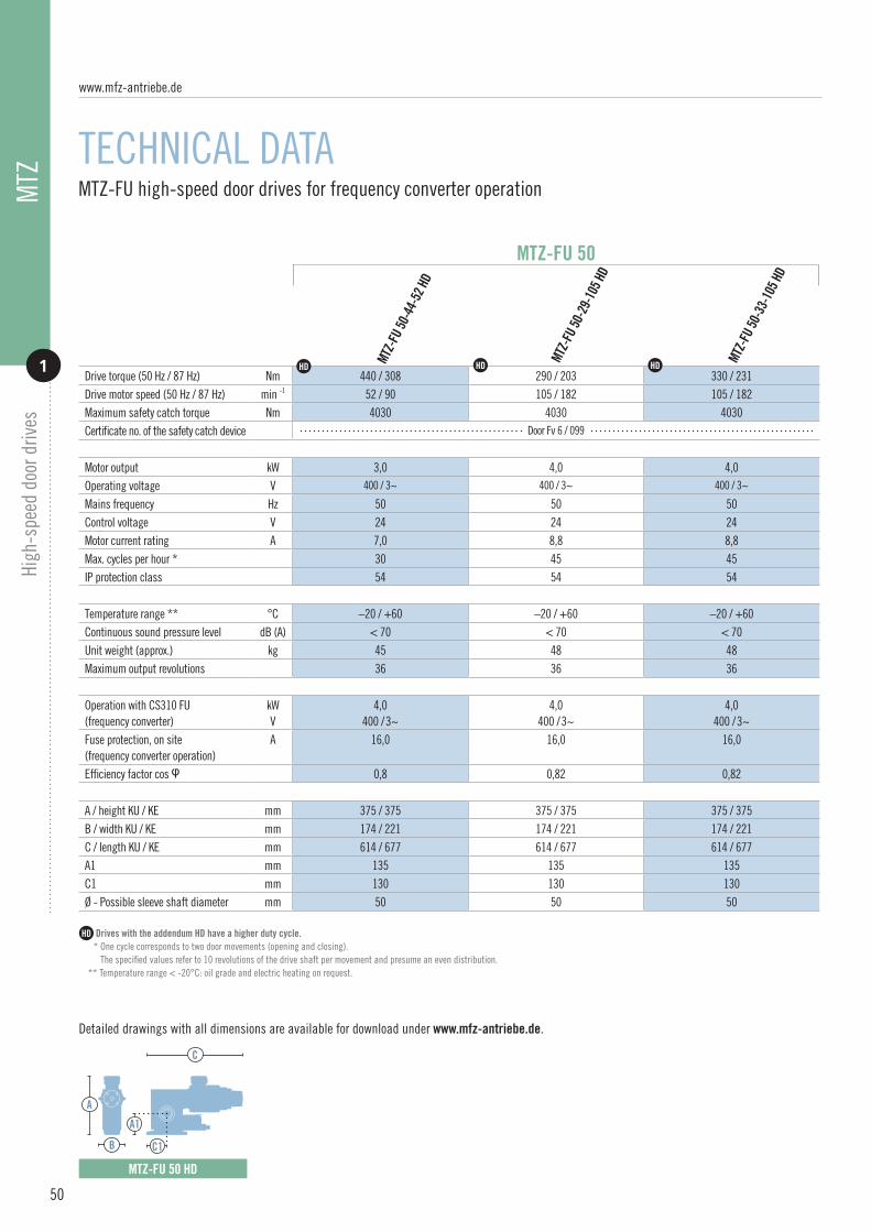
Drive torque (50 Hz / 87 Hz) Nm 440 / 308 290 / 203 330 / 231Drive motor speed (50 Hz / 87 Hz) min -1 52 / 90 105 / 182 105 / 182Maximum safety catch torque Nm 4030 4030 4030Certificate no. of the safety catch device Door Fv 6 / 099
Motor output kW 3,0 4,0 4,0Operating voltage V 400 / 3~ 400 / 3~ 400 / 3~
Mains frequency Hz 50 50 50Control voltage V 24 24 24Motor current rating A 7,0 8,8 8,8Max. cycles per hour * 30 45 45IP protection class 54 54 54 Temperature range ** °C –20 / +60 –20 / +60 –20 / +60Continuous sound pressure level dB (A) < 70 < 70 < 70Unit weight (approx.) kg 45 48 48Maximum output revolutions 36 36 36 Operation with CS310 FU (frequency converter)
kW V
4,0 400 / 3~
4,0 400 / 3~
4,0 400 / 3~
Fuse protection, on site (frequency converter operation)
A 16,0 16,0 16,0
Efficiency factor cos φ 0,8 0,82 0,82
A / height KU / KE mm 375 / 375 375 / 375 375 / 375B / width KU / KE mm 174 / 221 174 / 221 174 / 221C / length KU / KE mm 614 / 677 614 / 677 614 / 677A1 mm 135 135 135C1 mm 130 130 130Ø - Possible sleeve shaft diameter mm 50 50 50
MTZ-FU 50
HD HD HD
www.mfz-antriebe.de
50
MTZ MTZ-FU high-speed door drives for frequency converter operation
TECHNICAL DATA
High
-spe
ed d
oor d
rives
1
MTZ-FU 50 HD
C
C1
A1
B
A

Drives with the addendum HD have a higher duty cycle. * One cycle corresponds to two door movements (opening and closing). The specified values refer to 10 revolutions of the drive shaft per movement and presume an even distribution. ** Temperature range < -20°C: oil grade and electric heating on request.
Detailed drawings with all dimensions are available for download under www.mfz-antriebe.de.
51
MTZ
Hig
h-sp
eed
door
driv
es
1

MFZ Antriebe GmbH & Co. KGNeue Mühle 4D-48739 Legden, Germany
www.mfz-antriebe.de 03/
2018
/EN

SERVICE.
DIVERSITY.
QUALITY.
INDIVIDUAL SOLUTIONS.
THIS IS WHAT
DRIVES US.
2018
www.mfz-antriebe.de
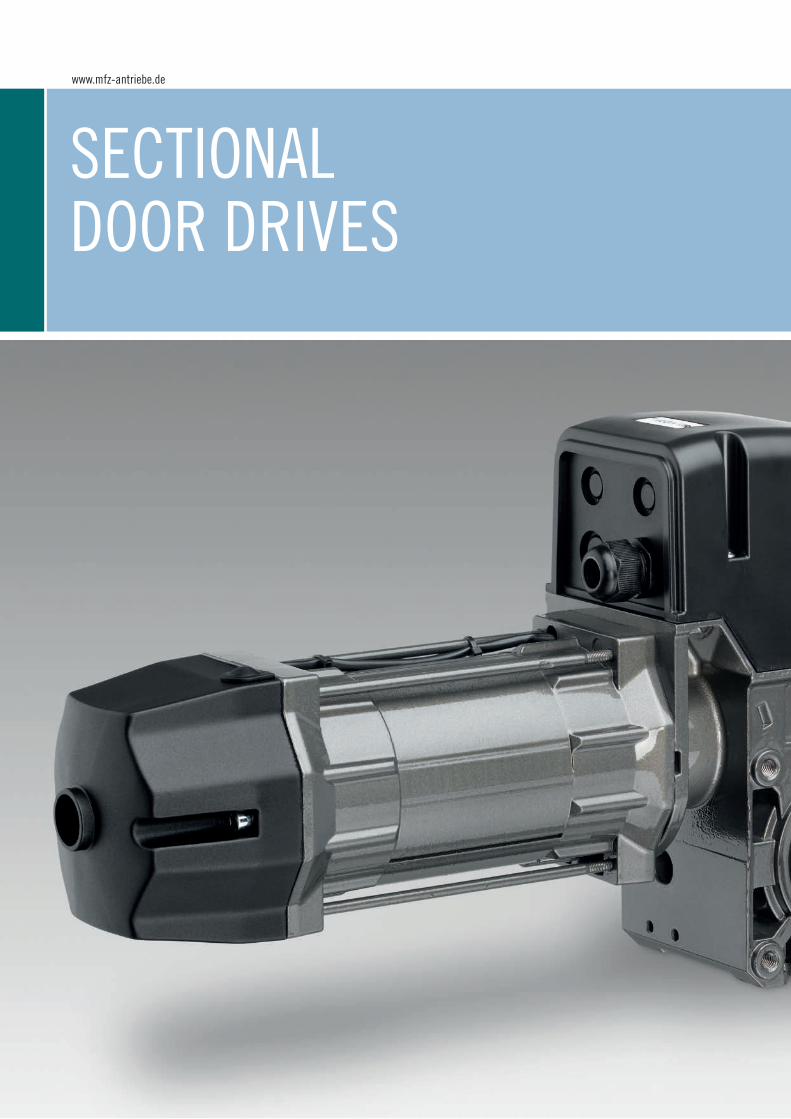
SECTIONAL DOOR DRIVES
www.mfz-antriebe.de

1
for spring-balanced sectional doors Starting on page 54
STA / STAC
2
for sectional doors without springsStarting on page 60
MDF
3
Overhead rails for spring-balanced sectional doorsStarting on page 66
STAI / STAIC
Section on sectional door drives
SECTIONAL DOOR DRIVES
53

STA / STACSTA / STAW Sectional door drives for spring-balanced doors STAC / STAWC Sectional door drives for spring-balanced doors with integrated control unit
The STA / STAW and STAC / STAWC series of drives are optimally designed for spring-balanced sectional doors. This guarantees a drive thatis developed especially for this particular application, with a special motor to supply a great deal of power in the smallest space. The drive is therefore extremely compact and its housing very slim.External or integrated controls: All drives in the STA / STAW series work on the basis of external controls, whereas the drives in the STAC / STAWC have integrated controls. We have the flexibility to quickly realise custom solutions for individual customer requirements at any time.
2 versions availableSTA / STAW external controlSTAC / STAWC integrated control
Pressure cast aluminium housing
Rolled worm shaft
Double worm shaft bearings
Standard 25.4 mm sleeve shaft.Special sleeve shaft on request.
Emergency operation via emergency hand crank (KU), emergency hand chain (KE),emergency unlocking device (E) or emergency unlocking device with spring reset (E-FR)
Straightforward conversion from crank to chain
Maintenance unlocking optional
End position setting viaelectronic absolute encoder ormechanical limit switch
Thermal protection in the motor windings
Higher motor duty cycle available. Designationby the addendum
Supply 230 / 400V / 50Hz / 3~ STA / STACor 230V / 50 Hz / 1~ STAW / STAWC(custom solutions on request)
Plug-in connections
Version with external or integrated control,for combination with an extensive control programmeSupply: 230 / 400V / 3~, 230V / 1~Frequency: 50 / 60 HzControl voltage: 24V-DC(Section 10 “Controls”)
Frequency converter control optional (STA only). Increasing the drive motor speed (operation with frequency converter) reduces the drive torque. The following applies in this case: Increasing the drive motor speed by 10% reduces the drive torque by 5%.Version FU-I with integrated frequency converterVersion FU-E with external frequency converter
Custom versions, such as different voltages and frequencies,higher protection classes and sleeve shaft diameters on request.
ATEX versions(Section 6 “Drives for use in explosion protected rooms)
Characteristics
01 11
03
05
08
09
02
04
06
07
10
13
14
15
12
16
17
STA / STAW STAC / STAWC
HD
www.mfz-antriebe.de
54

Sect
iona
l doo
r driv
es
1
05
11
06
13
17
HD
09
STA
/ STA
C
1
SECTIONAL DOOR DRIVES
KU KE E E-FR
14 15
55

56
Selecting the right sectional door drive
DOOR SIZE
The values in the table take into account a weight of 13 kg/m² and presume an exact spring balance.
In certain situations, the friction can be greater and this must be considered when calculating the values. A drive with a higher duty cycle (HD) should be chosen for door systems with above-average switching cycles.
302018 45 50
Straightforward drive selection
Door size
Door size in m2
STA / STAC 1-13-15 —- —- —- —-STA / STAC 1-11-19 —- —- —- —-STA / STAC 1-12-19 —- —- —- —-STA / STAC 1-14-19 —- —- —- —-STA / STAC 1-5-24 —- —- —- —-STA / STAC 1-10-24 —- —- —- —-STA / STAC 1-11-24 —- —- —- —-STA / STAC 1-10-30 —- —- —- —-STA / STAC 1-8-45 —- —- —- —-
STA / STAC 1-13-15 HD —- —- —- —-STA / STAC 1-12-19 HD —- —- —- —-STA / STAC 1-11-24 HD —- —- —- —-STA / STAC 1-10-30 HD —- —- —- —-
STAW / STAWC 1-7-19 —- —- —- —-STAW / STAWC 1-6-24 —- —- —- —-
HD
HD
HD
HD
m2 Drive=
Drives for doors with spring balance
!
X
X
X
X
X
X
X
X
X
X
X
X
X
X
X
www.mfz-antriebe.de
STA
/ STA
CSe
ctio
nal d
oor d
rives
1

Sectional door drives for spring-balanced doors
TECHNICAL DATA
57
Drives with the addendum HD have a higher duty cycle. * One cycle corresponds to two door movements (opening and closing). The specified values refer to 10 revolutions of the drive shaft per movement and presume an even distribution. ** Temperature range < -20°C: oil grade and electric heating on request.
Detailed drawings with all dimensions are available for download under www.mfz-antriebe.de.
HD
STA
/ STA
CSe
ctio
nal d
oor d
rives
1
STA 1
-13-
15
STAC
1-13
-15
Drive torque Nm 130 110 120 140Drive motor speed min -1 15 19 19 19Static holding torque Nm 600 600 600 600 Motor output kW 0,55 0,37 0,55 0,65Operating voltage V 230 / 400 / 3~ 230 / 400 / 3~ 230 / 400 / 3~ 230 / 400 / 3~
Mains frequency Hz 50 50 50 50Control voltage V 24 24 24 24Motor current rating A 3,1 / 1,8 3,5 / 2,0 4,1 / 2,4 3,5 / 2,0Max. cycles per hour * 20 20 20 20Fuse protection, on site (mains operation)
A 10,0 10,0 10,0 10,0
IP protection class 54 54 54 54 Temperature range ** °C -20 / +60 -20 / +60 -20 / +60 -20 / +60Continuous sound pressure level dB (A) < 70 < 70 < 70 < 70Unit weight (approx.) kg 15 15 15 15Maximum output revolutions 20 20 20 20 A / height KU / KE / E / E-FR mm 245 / 245 / 245 / 256 245 / 245 / 245 / 256B / width KU / KE / E / E-FR mm 104 / 104 / 104 / 116 104 / 104 / 104 / 116C / length KU / KE / E / E-FR mm 399 / 409 / 369 / 369 419 / 429 / 389 / 369A1 mm 55 55 55 55C1 mm 55 55 55 55Ø - Sleeve shaft diameter (standard) mm 25,4 25,4 25,4 25,4
STA / STAC
STA 1
-11-
19
STAC
1-11
-19
STA 1
-12-
19
STAC
1-12
-19
STA 1
-14-
19
STAC
1-14
-19
STAC
C
A
B C1
A1
STA
C
A
B C1
A1

58
Sectional door drives for spring-balanced doors
TECHNICAL DATA
www.mfz-antriebe.de
STA
/ STA
CSe
ctio
nal d
oor d
rives
1
STA
C
A
B C1
A1
STAC
C
A
B C1
A1
Drives with the addendum HD have a higher duty cycle. * One cycle corresponds to two door movements (opening and closing). The specified values refer to 10 revolutions of the drive shaft per movement and presume an even distribution. ** Temperature range < -20°C: oil grade and electric heating on request.
Detailed drawings with all dimensions are available for download under www.mfz-antriebe.de.
HD
STA 1
-5-2
4 ST
AC 1-
5-24
Drive torque Nm 50 100 110 100 80Drive motor speed min -1 24 24 24 30 45Static holding torque Nm 600 600 600 600 600 Motor output kW 0,25 0,37 0,55 0,55 0,55Operating voltage V 230 / 400 / 3~ 230 / 400 / 3~ 230 / 400 / 3~ 230 / 400 / 3~ 230 / 400 / 3~
Mains frequency Hz 50 50 50 50 50Control voltage V 24 24 24 24 24Motor current rating A 2,3 / 1,3 3,5 / 2,0 4,1 / 2,4 3,5 / 2,0 3,0 / 1,7Max. cycles per hour * 20 20 20 20 20Fuse protection, on site (mains operation)
A 10,0 10,0 10,0 10,0 10,0
IP protection class 54 54 54 54 54 Temperature range ** °C –20 / +60 –20 / +60 –20 / +60 –20 / +60 –20 / +60Continuous sound pressure level dB (A) < 70 < 70 < 70 < 70 < 70Unit weight (approx.) kg 15 15 15 15 15Maximum output revolutions 20 20 20 20 20 A / height KU / KE / E / E-FR mm 245 / 245 / 245 / 256 245 / 245 / 245 / 256B / width KU / KE / E / E-FR mm 104 / 104 / 104 / 116 104 / 104 / 104 / 116C / length KU / KE / E / E-FR mm 369 / 379 / 339 / 339 399 / 409 / 369 / 369A1 mm 55 55 55 55 55C1 mm 55 55 55 55 55Ø - Sleeve shaft diameter (standard) mm 25,4 25,4 25,4 25,4 25,4
STA / STAC
STA 1
-10-
24
STAC
1-10
-24
STA 1
-11-
24
STAC
1-11
-24
STA 1
-10-
30ST
AC 1-
10-3
0
STA 1
-8-4
5ST
AC 1-
8-45

59
STA HD
C
A
B C1
A1
STAW
Drives with the addendum HD have a higher duty cycle. * One cycle corresponds to two door movements (opening and closing). The specifi ed values refer to 10 revolutions of the drive shaft per movement and presume an even distribution. ** Temperature range < -20°C: oil grade and electric heating on request.
Detailed drawings with all dimensions are available for download under www.mfz-antriebe.de.
HD
STA
/ STA
CSe
ctio
nal d
oor d
rives
1Drive torque Nm 130 120 110 100 70 60Drive motor speed min -1 15 19 24 30 19 24Static holding torque Nm 600 600 600 600 600 600 Motor output kW 0,55 0,55 0,55 0,55 0,37 0,37Operating voltage V 230 / 400 / 3~ 230 / 400 / 3~ 230 / 400 / 3~ 230 / 400 / 3~ 230 / 1~ 230 / 1~
Mains frequency Hz 50 50 50 50 50 50Control voltage V 24 24 24 24 24 24Motor current rating A 3,1 / 1,8 3,0 / 1,7 3,0 / 1,7 3,0 / 1,7 6,2 6,2Max. cycles per hour * 30 30 30 30 8 8Fuse protection, on site (mains operation)
A 10 10 10 10 10 10
IP protection class 54 54 54 54 54 54 Temperature range ** °C –20 / +60 –20 / +60 –20 / +60 –20 / +60 –20 / +60 –20 / +60Continuous sound pressure level dB (A) < 70 < 70 < 70 < 70 < 70 < 70Unit weight (approx.) kg 23 23 23 23 23 23Maximum output revolutions 20 20 20 20 20 20 A / height KU / KE / E / E-FR mm 245 / 245 / 245 / 256 245 / 245 / 245 / 256B / width KU / KE / E / E-FR mm 136 / 191 / 136 / 136 104 / 104 / 104 / 116C / length KU / KE / E / E-FR mm 396 / 438 / 336 / 336 399 / 409 / 369 / 369A1 mm 55 55 55 55 55 55C1 mm 55 55 55 55 55 55Ø - Sleeve shaft diameter (standard) mm 25,4 25,4 25,4 25,4 25,4 25,4
STA HD
Drives with the addendum HD have a higher duty cycle. * One cycle corresponds to two door movements (opening and closing). The specifi ed values refer to 10 revolutions of the drive shaft per movement and presume an even distribution. ** Temperature range < -20°C: oil grade and electric heating on request.
Detailed drawings with all dimensions are available for download under www.mfz-antriebe.de.
STAWC
C
A
B C1
A1
STA 1
-13-
15 H
D
STA 1
-12-
19 H
D
STA 1
-11-
24 H
D
STA 1
-10-
30 H
D
STAW
1-7-
19
STAW
C 1-
7-19
STAW
1-6-
24
STAW
C 1-
6-24
HD HD HD HD 1~ 1~
C
A
B C1
A1
STAW / STAWC

MDFMDF Sectional door drives for doors without springs
The powerful MDF series drives are the optimum solution for sectional doors without springs. The maintenance-free safety catch device is already integrated and therefore offers the safest option for the door. With a complete series from 140 to 1650 Nm, MFZ provides the right solution in this seg-ment for every on-site situation. The drives are straightforward and easy to install thanks to their compact size. We have the flexibility to quickly realise custom solutions for individual customer requirements at any time.
Integrated safety catch device, independent of position and speed,free of maintenance and wear, integrated damping
Self-aligning bearings
Rolled worm shaft
High holding force via additional magnetic brake
Dimension between centre lines 145 mm or 120 mm(only for MDF 20 / MDF 30)
Emergency hand crank for emergency operation (KU)or emergency hand chain (KE)
Straightforward conversion from crank to chain
End position setting viaelectronic absolute encoder ormechanical limit switch
Thermal protection in the motor windings
Higher motor duty cycle available. Identified bythe addendum
Supply 230 / 400V / 50Hz / 3~(custom solutions on request)
Plug-in connections
Version with external control,for combination with an extensive control programmeSupply: 230 / 400V / 3~Frequency: 50 / 60 HzControl voltage: 24V-DC(Section 10 “Controls”)
Frequency converter control optional. Increasing the drive motor speed (operation with frequency converter) reduces the drive torque.The following applies in this case: Increasing the drive motor speed by 10% reduces the drive torque by 5%.
Custom versions, such as different voltages and frequencies,other drive motor speeds, higher protection classes andsleeve shaft diameters, on request.
Cable drums in different sizes and versions
Characteristics
01 10
12
13
03
05
04
06
07
1102
08
09
16
14
MDF 05 MDF 20 MDF 30 MDF 50
HD
15
www.mfz-antriebe.de
60

Sect
iona
l doo
r driv
es
2
MDF
05
10
02 06
08 12
1413 16
2
SECTIONAL DOOR DRIVES
MDF 60 MDF 70
KU KE
61
HD

62
Selection and technical data
CABLE DRUMS
STR
159-
8
STR
133-
8
STR
133-
6
STR
159-
10
STR
193-
8
Cable drums
Suspended weight kg 750 800 1350 1400 1350 1400 1350 1400 1400 1750Cable capacity m 9 6,5 11,5 9,5 11,0 10,0 12,5 11,0 14,0 12,0Cable diameter mm 6 8 8 10 8 10 8 10 10 12
Safety windings 2 2 2 2 2 2 2 2 2 2Material Aluminium Aluminium Aluminium Aluminium Steel Steel Steel Steel Steel Steel
Unit weight kg 7 7 10 10 13 13 15 15 20 20Delivery unit Quantity 2 (left / right) Marking 6L134
6R1346L1346R134
8L1608R160
10L16010R160
8L1938R193
10L19310R193
8L2198R219
10L21910R219
10L24410R244
12L24412R244
A I calculation diameter mm 167 167 192 192 212 214 242 244 269 271B I internal diameter mm 134 134 160 160 195 195 220 220 245 245C I external diameter mm 180 180 220 220 224 224 250 250 275 275D I width mm 176 176 251 251 260 280 240 220 250 220
STR
219-
10
STR
219-
8
STR
193-
10
STR
244-
10
STR
244-
12
www.mfz-antriebe.de
MDF
Sect
iona
l doo
r driv
es
2
Custom solutions on request.
Detailed drawings with all dimensions are available for download under www.mfz-antriebe.de.
Cable drum STR
C AB
D

Selecting the right MDF sectional door drive
SUSPENDED WEIGHTS
STR
193
STR
159
STR
133
STR
219
STR
244
Cable drum STR
Tubular shaft mm 133,0 159,0 193,7 219,1 244,5Calculation diameter mm 167 192 224 250 275
MDF 05-14-24 137 119 102 91 83
MDF 20-18-24 176 153 131 117 107
MDF 30-32-18 313 272 233 209 190MDF 30-32-24 313 272 233 209 190MDF 30-40-17 391 340 291 261 237MDF 30-40-24 391 340 291 261 237
MDF 50-75-16 732 637 546 489 445MDF 50-75-24 HD 732 637 546 489 445
MDF 60-100-17 977 849 728 652 593MDF 60-100-24 HD 977 849 728 652 593
MDF 70-140-17 HD 1367 1189 1019 913 830MDF 70-125-24 HD 1221 1062 910 815 741MDF 70-165-17 HD 1611 1402 1201 1076 979MDF 70-165-24 HD 1611 1402 1201 1076 979
Drives for doors wi-thout spring balance
!
63
MDF
Sect
iona
l doo
r driv
es
2
To select the optimum drive solution, you will need the calculation diameter of the chosen cable drum in mm, the diameter of the tubular shaft in mm and the suspended weight of the door in kg. With the help of these parameters, the appropriate MDF sectional door drive can be determined easily and reliably using this table.
Straightforward drive selection
Diameter Suspended weight
kgØ Drive+ =
Custom solutions on request.
Detailed drawings with all dimensions are available for download under www.mfz-antriebe.de.
Maximum suspended weight in kg
The values in the table take a 20% safety reserve into account. In certain situations, the friction can be greater and this must be considered when calculating the values.

64
Sectional door drives for doors without springs
TECHNICAL DATA
Drives with the addendum HD have a higher duty cycle. * Increasing the drive motor speed (operation with frequency converter) reduces the drive torque. The following applies in this case: increasing the drive motor speed by 10% reduces the drive torque by 5%. ** One cycle corresponds to two door movements (opening and closing). The specified values refer to 10 revolutions of the drive shaft per movement and presume an even distribution. *** Temperature range < -20°C: oil grade and electric heating on request.
Detailed drawings with all dimensions are available for download under www.mfz-antriebe.de.
Drive torque Nm 140 180 320 320 400 400Drive motor speed min - 1 24 24 18 24 17 24Maximum safety catch torque Nm 309 784 2680 2680 2680 2680Certificate no. of the safety catch device Door FV 6 / 092 Door FV 9 / 147/1 24042140-1
Motor output kW 0,55 1,1 1,1 1,7 1,7 1,7Operating voltage V 230 / 400 / 3~ 230 / 400 / 3~ 230 / 400 / 3~ 230 / 400 / 3~ 230 / 400 / 3~ 230 / 400 / 3~
Mains frequency Hz 50 50 50 50 50 50Control voltage V 24 24 24 24 24 24Motor current rating A 3,0 / 1,7 4,7 / 2,7 5,7 / 3,3 8,3 / 4,8 8,3 / 4,8 8,3 / 4,8Max. cycles per hour * 20 20 20 20 20 20Fuse protection, on site (mains operation) A 10 10 10 10 10 10IP protection class 54 54 54 54 54 54
Temperature range ** °C –20 / +60 –20 / +60 –20 / +60 –20 / +60 –20 / +60 –20 / +60Continuous sound pressure level dB (A) < 70 < 70 < 70 < 70 < 70 < 70Unit weight (approx.) kg 19 23 28 30 30 30Maximum output revolutions 13 18 18 18 18 18
Operation with CS310 FU (frequency converter)
kW V
0,75 230 / 1~
1,5 400 / 3~
1,5 400 / 3~
2,2 400 / 3~
2,2 400 / 3~
2,2 400 / 3~
Fuse protection, on site (frequency converter operation)
A 10 10 10 10 10 10
Efficiency factor cos φ 0,76 0,78 0,71 0,8 0,8 0,8
A / height KU / KE mm 290 / 290 318 / 318 335 / 335 335 / 335 335 / 335 335 / 335B / width KU / KE mm 111 / 192 114 / 192 122 / 192 122 / 192 122 / 192 122 / 192C / length KU / KE mm 442 / 484 501 / 589 536 / 625 536 / 625 536 / 625 536 / 625A1 mm 100 145 145 145 145 145C1 mm 85 110 130 130 130 130Ø - Sleeve shaft diameter (standard) mm 30 30 40 40 40 40
MDF 30
MDF 3
0-32
-18
MDF 3
0-32
-24
MDF 3
0-40
-17
MDF 2
0-18
-24
MDF 0
5-14
-24
MDF 3
0-40
-24
HD
MDF 20MDF 05
MDF 20
C
A
B C1
A1
MDF 05
C
A
B
A1
C1
MDF 30
C
A
B C1
A1
www.mfz-antriebe.de
MDF
Sect
iona
l doo
r driv
es
2

MDF 6
0-10
0-24
Drive torque Nm 750 750 1000 1000 1400 1250 1650 1650Drive motor speed min - 1 16 24 17 24 17 24 17 24Maximum safety catch torque Nm 4030 4030 3974 3974 7738 7738 7738 7738Certificate no. of the safety catch device Door FV 6 / 099 11-003601-PRO1 10-000808-PRO3
Motor output kW 2,2 3,0 3,0 4,0 4,0 4,0 4,4 5,5Operating voltage V 230 / 400 / 3~ 230 / 400 / 3~ 230 / 400 / 3~ 230 / 400 / 3~ 230 / 400 / 3~ 230 / 400 / 3~ 230 / 400 / 3~ 230 / 400 / 3~
Mains frequency Hz 50 50 50 50 50 50 50 50Control voltage V 24 24 24 24 24 24 24 24Motor current rating A 11,3 / 6,5 12,1 / 7,0 12,1 / 7,0 18,2 / 10,5 18,2 / 10,5 18,2 / 10,5 19,5 / 11,3 22,8 / 13,2Max. cycles per hour * 20 30 20 30 30 30 30 30Fuse protection, on site (mains operation) A 16 / 10 16 / 10 16 / 10 20 / 16 20 / 16 20 / 16 20 / 16 25 / 16IP protection class 54 54 54 54 54 54 54 54
Temperature range ** °C –20 / +60 –20 / +60 –20 / +60 –20 / +60 –20 / +60 –20 / +60 –20 / +60 –20 / +60Continuous sound pressure level dB (A) < 70 < 70 < 70 < 70 < 70 < 70 < 70 < 70Unit weight (approx.) kg 39 43 67 72 72 72 77 81Maximum output revolutions 36 36 36 36 36 36 36 36
Operation with CS310 FU (frequency converter)
kW V
3,0 400 / 3~
3,0 400 / 3~
3,0 400 / 3~
5,5 400 / 3~
5,5 400 / 3~
5,5 400 / 3~
5,5 400 / 3~
7,5 400 / 3~
Fuse protection, on site (frequency converter operation)
A 10 10 10 16 16 16 16 25
Efficiency factor cos φ 0,7 0,8 0,8 0,73 0,73 0,73 0,78 0,78
A / height KU / KE mm 341 / 341 375 / 375 433 / 433 460 / 481 460 / 481 460 / 481 491 / 491 491 / 491B / width KU / KE mm 122 / 195 174 / 220 174 / 221 194 / 244 194 / 244 194 / 244 216 / 255 216 / 255C / length KU / KE mm 576 / 638 614 / 677 687 / 750 766 / 873 766 / 873 766 / 873 785 / 893 785 / 893A1 mm 135 135 185 200 200 200 200 200C1 mm 130 130 200 200 200 200 200 200Ø - Sleeve shaft diameter (standard) mm 50 50 50 55 55 55 55 55
MDF 70
MDF 6
0-10
0-17
MDF 7
0-14
0-17
MDF 7
0-16
5-17
MDF 5
0-75
-24
MDF 5
0-75
-16
MDF 7
0-16
5-24
HD
MDF 60MDF 50
MDF 7
0-12
5-24
MDF 50 HD
C
A
B C1
A1
MDF 50
C
A
B
A1
C1
MDF 60 / 70
C
A
B C1
A1
HD HD HD HD HD HD HD
Drives with the addendum HD have a higher duty cycle. * Increasing the drive motor speed (operation with frequency converter) reduces the drive torque. The following applies in this case: increasing the drive motor speed by 10% reduces the drive torque by 5%. ** One cycle corresponds to two door movements (opening and closing). The specified values refer to 10 revolutions of the drive shaft per movement and presume an even distribution. *** Temperature range < -20°C: oil grade and electric heating on request.
Detailed drawings with all dimensions are available for download under www.mfz-antriebe.de.
65
MDF
Sect
iona
l doo
r driv
es
2

STAI / STAICSTAI Overhead rails for spring-balanced sectional doors STAIC Overhead rails for spring-balanced sectional doors with integrated control
STAI drives are robust industrial door drives with a ceiling-mounted rail. They are the ideal drive solution for spring-balanced sectional doors with low-profile lintel fittings or insufficient lateral space for installation. Their robust construction also makes them ideal for use in underground car parks. Doors with a maximum height of 4,500 can be automated. The drive motors are based on the proven STA drives. All drives in the STAI series work on the basis of external controls, whereas the drives in the STAIC series have integrated controls. We have the flexibility to quickly realise custom solutions for individual customer requirements at any time.
2 versions availableSTAI external controlSTAIC integrated control
Pressure cast aluminium housing
Rolled worm shaft
Double worm shaft bearings
Emergency operation via unlocking mechanism in theguide carriage of the rail
End position setting viaelectronic absolute encoder ormechanical limit switch
Thermal protection in the motor windings
Higher motor duty cycle available. Designationby the addendum
Supply 230 / 400V / 50Hz / 3~(custom solutions on request)
Plug-in connections
Version with external or integrated control,for combination with an extensive control programmeSupply: 230 / 400V / 3~Frequency: 50 / 60 HzControl voltage: 24V-DC(Section 10 “Controls”)
Frequency converter control optional. Increasing the drive motor speed (operation with frequency converter) reduces the drive torque.The following applies in this case: Increasing the drive motor speed by 10% reduces the drive torque by 5%.
Custom versions, such as different voltages and frequencies,drive motor speeds and higher protection classes on request.
Setup and installation componentsPage 69
Characteristics
01
10
11
12
03
05
04
06
07
08
09
13
14
02
HD
www.mfz-antriebe.de
66
STAI STAIC

Sect
iona
l doo
r driv
es
3
STAI
/ ST
AIC
05
1211
14
3
SECTIONAL DOOR DRIVES
06 08 10
HD
67

68
Overhead rails for spring-balanced doors
TECHNICAL DATA
www.mfz-antriebe.de
STAI
/ ST
AIC
Sect
iona
l doo
r driv
es
3
Drives with the addendum HD have a higher duty cycle. * One cycle corresponds to two door movements (opening and closing). The specified values refer to 10 revolutions of the drive shaft per movement and presume an even distribution. ** Temperature range < -20°C: oil grade and electric heating on request. *** The values in the table take into account a weight of 13 kg/m² and presume an exact spring balance. In certain situations, the friction can be greater and this must be considered when calculating the values. A drive with a higher duty cycle (HD) should be chosen for door systems with above-average switching cycles.
Detailed drawings with all dimensions are available for download under www.mfz-antriebe.de.
HD
STAI
1-10
-30
STAI
C 1-
10-3
0Drive torque Nm 100 100 80 80Drive motor speed min -1 30 30 45 45Static holding torque Nm 600 600 600 600 Motor output kW 0,55 0,55 0,55 0,55Operating voltage V 230 / 400 / 3~ 230 / 400 / 3~ 230 / 400 / 3~ 230 / 400 / 3~Mains frequency Hz 50 50 50 50Control voltage V 24 24 24 24
Motor current rating A 3,5 / 2,0 3,0 / 1,7 3,3 / 1,9 3,0 / 1,7Max. cycles per hour * 15 25 15 25Fuse protection, on site (mains operation) A 10,0 10,0 10,0 10,0IP protection class 54 54 54 54 Temperature range ** °C –20 / +60 –20 / +60 –20 / +60 –20 / +60Continuous sound pressure level dB (A) < 70 < 70 < 70 < 70Unit weight kg 13 18 15 18Maximum output revolutions 40 40 40 40 Maximum door size *** m2 30 30 30 30Door travel speed m/s 0,1 0,1 0,15 0,15
A / height mm 245 245 245 245B / width mm 104 136 104 136C / length mm 369 336 369 336A1 mm 55 55 55 55C1 mm 55 55 55 55Ø - Sleeve shaft diameter (standard) mm 25,4 25,4 25,4 25,4
STAI / STAIC
STAI
1-10
-30 H
D
STAI
C
A
B C1
A1
STAIC
C
A
B C1
A1
STAI HD
C
A
B C1
A1
STAI
1-8-
45ST
AIC
1-8-
45
STAI
1-8-
45 H
D
HD HD

Overhead rails for spring-balanced doors
ACCESSORIES
STAI rail Article no. STAI suspension set Article no. STAI mounting bracket Article no.max. door height 2500 mm, installation depth 3897 mm
155271 For installation of the STAI rail max. lintel height 960 mm
max. section height 625 mm
For a lintel height > 960 mm, a second set has
to be used
140535 For the connectionof the STAI drive and STAI rail
158392
max. door height 3500 mm, installation depth 4897 mm
155272
max. door height 4500 mm, installation depth 5897 mm
155273
69
STAI
/ ST
AIC
Sect
iona
l doo
r driv
es
3
Drives with the addendum HD have a higher duty cycle. * One cycle corresponds to two door movements (opening and closing). The specified values refer to 10 revolutions of the drive shaft per movement and presume an even distribution. ** Temperature range < -20°C: oil grade and electric heating on request. *** The values in the table take into account a weight of 13 kg/m² and presume an exact spring balance. In certain situations, the friction can be greater and this must be considered when calculating the values. A drive with a higher duty cycle (HD) should be chosen for door systems with above-average switching cycles.
Detailed drawings with all dimensions are available for download under www.mfz-antriebe.de.
Products
3897 / 4897 / 5897
183
396
3760 / 4760 / 5760
265

MFZ Antriebe GmbH & Co. KGNeue Mühle 4D-48739 Legden, Germany
www.mfz-antriebe.de 03/
2018
/EN

SERVICE.
DIVERSITY.
QUALITY.
INDIVIDUAL SOLUTIONS.
THIS IS WHAT
DRIVES US.
2018
www.mfz-antriebe.de

FIRE-PROOF DOOR DRIVES
www.mfz-antriebe.de

1
Fire-proof chain drives for roller shutters Starting on page 72
FTU
2
Fire-proof control for fire-proof chain drives FTUStarting on page 78
CS310 / CS310 FTU
3
Fire-proof control for standard roller shutter and sectional door drivesStarting on page 80
CS310 FS
Section on fire-proof door drives
FIRE-PROOF DOOR DRIVES
71

FTUFire-proof chain drives for fire doors
Powerful and robust technology
Spur gear unit, not self-arresting
Magnetic brake (230V~)to support the gate load during normal operation
Centrifugal brake (230V~)for controlled closing in case of fire
End position setting viamechanical limit switch
Thermal protection in the motor windings
Supply 230 / 400V / 50Hz / 3~(custom solutions on request)
Plug connections (control unit side)
Version with special control for fire doorsCS310 with and without UPSSupply: 230 / 400V / 3~Frequency: 50 / 60 HzControl voltage: 24V-DC(pages 78-79)
Can be combined with a comprehensive range of accessories(page 77 – consoles MK - FT)(Section 2 “Safety catch devices”)
Characteristics
01
09
06
08
10
The FTU series drives were designed especially for fire doors. They form a complete series from 250 to 2200 Nm. A roller chain connects them to the shaft of the door. They close independently and automatically in case of fire, with no energy supply. In normal operation, the power-operated door is ope-ned and closed again by a three-phase current motor. The gear mechanism consists of a non-self-arresting spur gear unit, a centrifugal and magnetic brake, an electric motor and limit switches. A magnetic brake supports the load of the gate and is released immediately in case of fire. The centrifugal brake limits the movement speed of the gate. Note: A separate safety catch device is required for doors that have to be protected against falling. We also have the flexibility to quickly realise custom solutions for individual customer requirements at any time.
02
03
04
05
07
FTU 05 FTU 5 FTU 6, FTU 7FTU 3, FT 4
www.mfz-antriebe.de
72

Fire
-pro
of d
oor d
rives
1
FTU
1
FIRE-PROOF DOOR DRIVES
0503
09 10
02
04
73

74
Selecting the right FTU fire-proof chain drive
SUSPENDED WEIGHTS
The values in the table take into account 20% safety reserve and a lamella thickness of 25 mm. In certain situations, e.g. for additional door seals or double skin profiles, the friction can be greater and this must be considered when calculating the values.
Straightforward drive selection
kgØ Drive+ =
133,0
108,0
101,6
159,0
177,8
193,7
244,5
273,0
298,5
323,9
Diameter (Ø outside) of the winding shaft in mm
FTU 05-25-20 322 307 258 222 201 186 167 151 137 126 117FTU 3-50-20 644 613 516 443 402 373 334 303 274 252 234FTU 4-70-20 902 858 723 620 562 521 468 424 383 352 327FTU 5-105-20 1353 1288 1084 931 844 783 702 635 575 529 491FTU 6-140-20 1804 1717 1445 1241 1126 1044 936 847 766 706 654FTU 7-220-20 2834 2698 2271 1950 1769 1641 1471 1331 1204 1109 1028
219,1Gear ratio 1:1
133,0
108,0
101,6
159,0
177,8
193,7
244,5
273,0
298,5
323,9
FTU 05-25-20 644 614 516 444 402 372 334 302 274 252 234FTU 3-50-20 1288 1226 1032 886 804 746 668 606 548 504 468FTU 4-70-20 1798 1717 1445 1241 1125 1043 936 846 764 705 654FTU 5-105-20 2706 2576 2168 1862 1688 1566 1404 1270 1150 1058 982FTU 6-140-20 3608 3434 2890 2482 2252 2088 1872 1694 1532 1412 1308FTU 7-220-20 5668 5396 4542 3900 3538 3282 2942 2692 2408 2218 2056
219,1Gear ratio 2:1
www.mfz-antriebe.de
FTU
Fire
-pro
of d
oor d
rives
1
To select the optimum drive solution, you will need the diameter of the winding shaft in mm and the armour weight of the door in kg. With the help of these parameters, the appropriate fire-proof door drive can be determined easily and reliably using this table.
Diameter Winding shaft Suspended weight

The values in the table take into account 20% safety reserve and a lamella thickness of 25 mm. In certain situations, e.g. for additional door seals or double skin profiles, the friction can be greater and this must be considered when calculating the values.
133,0
108,0
101,6
159,0
177,8
193,7
244,5
273,0
298,5
323,9
Diameter (Ø outside) of the winding shaft in mm
FTU 05-25-20 966 921 774 666 603 558 501 453 411 378 351FTU 3-50-20 1932 1839 1548 1329 1206 1119 1002 909 822 756 702FTU 4-70-20 2697 2575 2168 1861 1687 1564 1404 1269 1149 1057 981FTU 5-105-20 4059 3864 3252 2793 2532 2349 2106 1905 1725 1587 1473FTU 6-140-20 5412 5151 4335 3723 3378 3132 2808 2541 2298 2118 1962FTU 7-220-20 8502 8094 6813 5850 5307 4923 4413 3993 3612 3327 3084
219,1
133,0
108,0
101,6
159,0
177,8
193,7
244,5
273,0
298,5
323,9
FTU 05-25-20 1224 1167 980 844 764 707 635 574 521 479 445FTU 3-50-20 2447 2329 1961 1683 1528 1417 1269 1151 1041 958 889FTU 4-70-20 3416 3262 2746 2358 2137 1981 1778 1607 1456 1339 1243FTU 5-105-20 5141 4894 4119 3538 3207 2975 2668 2413 2185 2010 1866FTU 6-140-20 6855 6525 5491 4716 4279 3967 3557 3219 2911 2683 2485FTU 7-220-20 10769 10252 8630 7410 6722 6236 5590 5058 4575 4214 3906
219,1
133,0
108,0
101,6
159,0
177,8
193,7
244,5
273,0
298,5
323,9
FTU 05-25-20 1449 1382 1161 999 905 837 752 680 617 567 527FTU 3-50-20 2898 2759 2322 1994 1809 1679 1503 1364 1233 1134 1053FTU 4-70-20 4045 3863 3252 2792 2531 2346 2106 1903 1724 1586 1472FTU 5-105-20 6089 5796 4878 4190 3798 3524 3159 2858 2588 2381 2210FTU 6-140-20 8118 7727 6503 5585 5067 4698 4212 3812 3447 3177 2943FTU 7-220-20 12753 12141 10220 8775 7961 7385 6620 5990 5418 4991 4626
219,1
Gear ratio 3:1
Gear ratio 3.8:1
Gear ratio 4.5:1
75
FTU
Fire
-pro
of d
oor d
rives
1
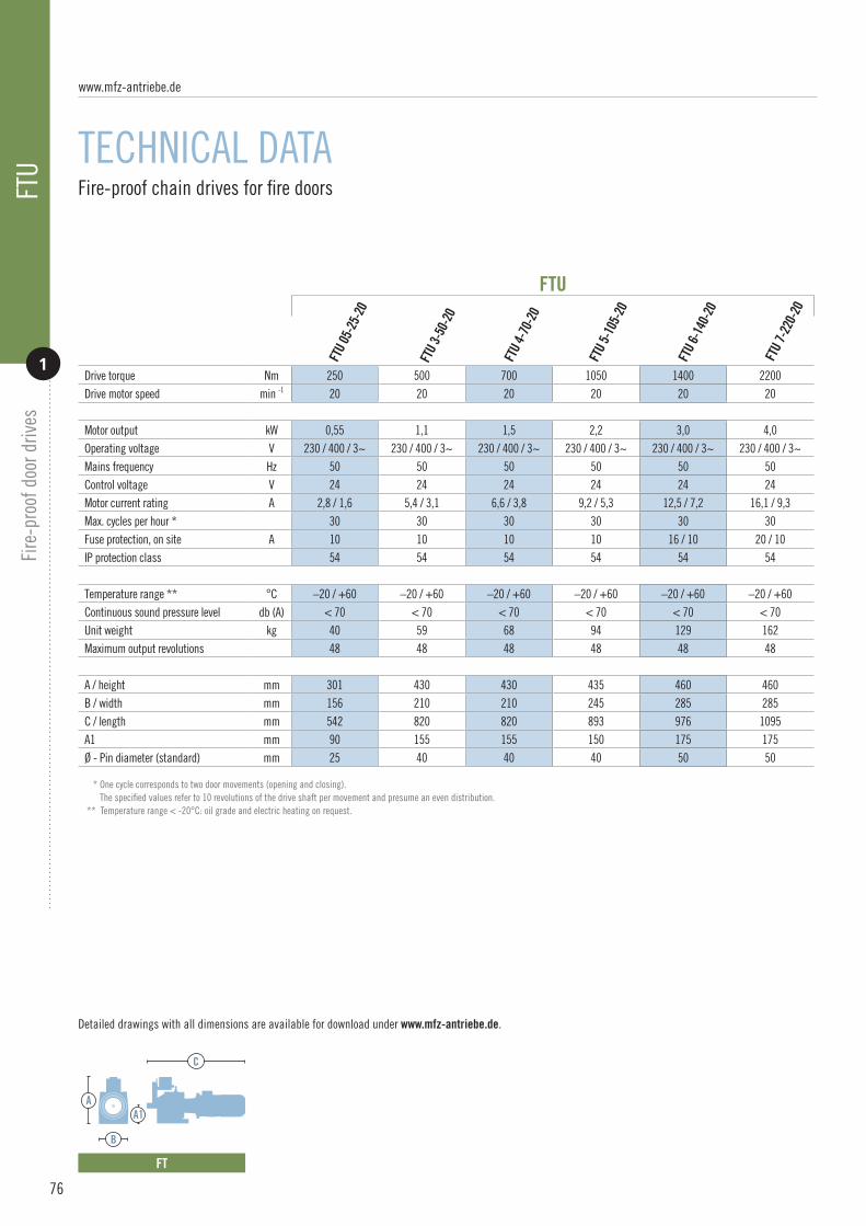
76
Fire-proof chain drives for fire doors
TECHNICAL DATA
FTU
3-50
-20
FTU
05-2
5-20
FTU
6-14
0-20
FTU
7-22
0-20
FTU
5-10
5-20
FTU
4-70
-20
Drive torque Nm 250 500 700 1050 1400 2200Drive motor speed min -1 20 20 20 20 20 20
Motor output kW 0,55 1,1 1,5 2,2 3,0 4,0Operating voltage V 230 / 400 / 3~ 230 / 400 / 3~ 230 / 400 / 3~ 230 / 400 / 3~ 230 / 400 / 3~ 230 / 400 / 3~Mains frequency Hz 50 50 50 50 50 50Control voltage V 24 24 24 24 24 24Motor current rating A 2,8 / 1,6 5,4 / 3,1 6,6 / 3,8 9,2 / 5,3 12,5 / 7,2 16,1 / 9,3Max. cycles per hour * 30 30 30 30 30 30Fuse protection, on site A 10 10 10 10 16 / 10 20 / 10IP protection class 54 54 54 54 54 54
Temperature range ** °C –20 / +60 –20 / +60 –20 / +60 –20 / +60 –20 / +60 –20 / +60Continuous sound pressure level db (A) < 70 < 70 < 70 < 70 < 70 < 70Unit weight kg 40 59 68 94 129 162Maximum output revolutions 48 48 48 48 48 48
A / height mm 301 430 430 435 460 460B / width mm 156 210 210 245 285 285C / length mm 542 820 820 893 976 1095A1 mm 90 155 155 150 175 175Ø - Pin diameter (standard) mm 25 40 40 40 50 50
FTU
Detailed drawings with all dimensions are available for download under www.mfz-antriebe.de.
* One cycle corresponds to two door movements (opening and closing). The specified values refer to 10 revolutions of the drive shaft per movement and presume an even distribution. ** Temperature range < -20°C: oil grade and electric heating on request.
FT
C
A
B
A1
www.mfz-antriebe.de
FTU
Fire
-pro
of d
oor d
rives
1

Detailed drawings with all dimensions are available for download under www.mfz-antriebe.de.
MK-FT
Used for FT 05 FT 3 / FT4 FT 5 FT 6 / FT 7Article no. 163 310 158 822 118 639 149 062
Unit weight kg 10,8 11,9 19,5 17,9
A mm 260 260 350 400B mm 280 280 400 400C mm 42 42 55 42D mm 13,5 13,5 17 17E mm 130 90 205 260F mm 110 185 170 —-G mm 9 13 16 —-
MK2-
FT 2-
4
MK2-
FT 05
MK8-
FT 6-
7
MK7-
FT 5
Consoles for fire-proof chain drives FTU
ACCESSORIES
MK2-FT / MK7-FT MK8-FT
B
A
E
D
CA
E
B
D
G
FC
77
FTU
Fire
-pro
of d
oor d
rives
1

78
for fi re-proof chain drives FTU
CONTROLS
CS 310
The CS 310 comfort automatic control unit is a universally compatible control system for industrial door drives as well as fi re-proof door drives with magnetic brake (FTU). It has numerous useful control functions for this fi eld of application. In normal operation, the CS 310 works as a standard door control unit with functioning safety devices. Automatic closing is realised via the fi re alarm system in case of fi re, and by releasing the magnetic brake in case of power failure. With and without active safety edge in both cases. With numerous connection and expansion possibilities, even complex control requirements can be readily met.
Operating voltage V 230 / 400 / 3~Mains frequency Hz 50Control voltage V 24
Max. load kW (A) 2.2 (8.0)Protection class IP 65Temperature range °C –10 / +40Dimensions, W x H x D mm 215 x 275 x 190Unit weight kg 1,8
Technical data
Functions· Control of the magnetic brake via relay output· Emergency closing via fi re alarm contact· Emergency opening via fi re alarm contact (only with 400V / 3~ supply)· Partial opening via fi re alarm contact (only with 400V / 3~ supply)· Automatic closing in case of power failure· 4 programmable relay outputs with 44 functions· 2 programmable inputs with 27 functions· Direction of rotation change via circuit board button / display· Integrated door operation counter· Programmable service alarm (PIN code protected)
End position setting· via mechanical limit switch
Operation· 3-button input unit· LCD monitor with clear text display· 3-button navigation / status and diagnostic messages· Integrated error memory (readout of all error messages including frequency and cycle of last occurrence)
Confi guration and connections· Connection of fi re alarm contact (NO / NC)· Transformer switchable from 230V / 3~ to 400V / 3~· Short-circuit proof low voltage· Supply for external devices (24V-DC / 500 mA and 230V-AC / 1A)· Airswitch strip, 8K2, optosensor can be connected· Interface for connecting expansion modules· Plug-in connection for HF receiver unit· Illuminated buttons (fi nd in the dark)· Protective housing for the circuit board· Adjustable, pre-assembled wall brackets
CS 310
www.mfz-antriebe.de
CS 3
10 /
CS 3
10 F
TUFi
re-p
roof
doo
r driv
es
2

CS 310 FTU
Functions· Control of the magnetic brake via relay output· UPS to supply the magnetic brake in case of power failure· Automatic closing in case of fire· 4 programmable relay outputs with 44 functions· 2 programmable inputs with 27 functions· Direction of rotation change via circuit board button / display· Integrated door operation counter· Programmable service alarm (PIN code protected)
End position setting · via mechanical limit switch
Operation · 3-button input unit· LCD monitor with clear text display· 3-button navigation / status and diagnostic messages· Integrated error memory (readout of all error messages· including frequency and cycle of last occurrence)
Configuration and connections· Connection of fire alarm contact (NO / NC)· Transformer switchable from 230V / 3~ to 400V / 3~· Short-circuit proof low voltage· Supply for external devices (24V-DC / 500 mA and 230V-AC / 1A)· Airswitch strip, 8K2, optosensor can be connected· Interface for connecting expansion modules· Plug-in connection for HF receiver unit· Illuminated buttons (find in the dark)· Protective housing for the circuit board· Adjustable, pre-assembled wall brackets
CS 310 FTUBased on the CS 310 comfort automatic control unit, the CS 310 FTU has an additional power supply for the magnetic brake of the FTU drive. In normal operation, the CS 310 FTU works as a standard door control unit with functioning safety devices. The magnetic brake continues to be supplied by the connected UPS system in case of a power failure. Automatic closing is realised via the fire alarm system in case of fire, independently of the mains supply. With numerous connection and expansion possibilities, even complex control requirements can be readily met.
Input voltage V 230 / 1~Output voltage V 230 / 1~Frequency Hz 50
Output VA 500IP protection class 40Temperature range °C 0 / +40Dimensions, W x H x D mm 235 x 390 x 110Unit weight kg 11
Operating voltage V 230 / 400 / 3~Mains frequency Hz 50Control voltage V 24
Max. load kW (A) 2.2 (8.0)Protection class IP 65Temperature range °C –10 / +40Dimensions, W x H x D mm 245 x 455 x 190Unit weight kg 1,8
Technical data
CS 310
UPS
CS 3
10 /
CS 3
10 F
TUFi
re-p
roof
doo
r driv
es
2
79

80
Fire-proof control for standard roller shutter and sectional door drives
FIRE-PROOF CONTROL
CS 310 FS
CS 310 FS
Normal operation. In normal operation, the CS 310 works as a standard door control unit with functioning safety devices. The motor is supplied directly with 400V / 3~. The door can be opened and closed.
Power failure · The motor is supplied by the UPS system. Now the gate system can only be closed.
Fire · An output of the fire alarm system can be linked to the CS 310 FS (NO or NC). Now the door can be closed (not opened) in case of fire. Directly when the mains supply is available, or via the UPS system in case of power failure.
· In both cases with active safety edge (stop only).
Functions· For standard roller shutter and sectional door drives· Closing via UPS system in case of power failure· Emergency closing via fire alarm contact with mains supply or UPS· All other functions same as CS 310 (catalogue “Controls”, page 135)
End position setting· Via mechanical limit switches or absolute encoder· Setting via circuit board button or plug-in LCD monitor
Operation· Buttons on the main board and LEDs for status message (standard)· Plug-in LCD monitor with clear text display (optional)· 3-button navigation / status and diagnostic messages
Configuration and connections· Straightforward commissioning according to plug & play principle· Connection of fire alarm contact· All other characteristics same as CS 310 (catalogue “Controls”, page 135)
Capacity· With fully charged batteries, 1 closing cycle can be guaranteed for a period of 24 hours
Operating voltage V 400 / 3~
Mains frequency Hz 50 / 60Control voltage V 24
Max. load kW (A) 2.2 (8.0)Protection class IP 65Temperature range °C –10 / +45Dimensions, W x H x D (external) mm 215 x 275 x 190Unit weight (external) kg 1,8
The CS 310 comfort automatic control unit is a universally compatible control system for industrial door drives. It can also be combined with standard roller shutter and sectional door drives and used in “fire-proof” applications. The system consists of a door drive, the CS 310 control unit and an unin-terruptible power supply (UPS). In case of a power failure, the UPS system is used for the one-time closing of a door system. The system is fully wired on delivery. Installation and commissioning are straightforward according to the plug & play principle. The control unit can be linked to a fire alarm system and features a programmable input that is compatible with all output types and features of the fire alarm system. With numerous connection and expansion possibilities, even complex control requirements can be readily met. (Section 10 “Controls”, page 135)
Technical data CS 310
www.mfz-antriebe.de
CS 3
10 F
SFi
re-p
roof
doo
r driv
es
3

Type UPS 400 / 1000 VA UPS 400 / 2000 VA UPS 400 / 5000 VAInput voltage V 400 / 3~ 400 / 3~ 400 / 3~Output voltage V 400 / 3~ 400 / 3~ 400 / 3~
Frequency Hz 50 50 50Output VA 1000 2000 5000IP protection class 40 40 40Temperature range °C 0 / 40 0 / 40 0 / 40Dimensions, W x H x D mm 440 x 590 x 170 440 x 590 x 170 1250 x 620 x 180
Unit weight kg 18 35 160
Used for MDF 05-14-12MDF 05-10-12 HDMDF 05-14-24MDF 20-22-12MDF 20-15-12 HDMDF 20-18-24MDF 30-30-12MDF 30-42-12MDF 30-50-12MDF 30-27-12 HDMDF 30-32-24MDF 30-40-24MDF 50-75-10MDF 50-75-10 HDSTA 1-13-15STA 1-13-15 HDSTA 1-11-19STA 1-12-19STA 1-12-19 HDSTA 1-14-19STA 1-10-24STA 1-11-24STA 1-11-24 HDSTA 1-10-30STA 1-10-30 HDSTA 1-8-45STAI 1-10-30STAI 1-10-30 HDSTAI 1-8-45STAI 1-8-45 HD
MDF 50-75-24 HDMDF 60-100-9MDF 60-140-9 HD
MDF 70-165-8 HDMDF 70-200-8 HD
Technical data, UPS
The UPS system is a self-contained unit and can be easily connected as a plug & play component. It is suitable for supplying various drive types for roller shutters and sectional doors according to the table above.
81
CS 3
10 F
SFi
re-p
roof
doo
r driv
es
3

MFZ Antriebe GmbH & Co. KGNeue Mühle 4D-48739 Legden, Germany
www.mfz-antriebe.de 03/
2018
/EN

SERVICE.
DIVERSITY.
QUALITY.
INDIVIDUAL SOLUTIONS.
THIS IS WHAT
DRIVES US.
2018
www.mfz-antriebe.de

ATEXwww.mfz-antriebe.de

1
Roller shutter drives | Sectional door drives Starting on page 84
MDF EX / STA EX
2
ControlsStarting on page 88
CS EX / BS EX
3
Switching amplifiers | Control and safety elementsStarting on page 92
EX ACCESSORIES
Section on drives for explosion protected areas
ATEX
83

ATEXMDF Ex Roller shutter drives for explosion protected areas STA Ex Sectional door drives for explosion protected areas
2 available model seriesMDF Ex for roller shuttersSTA Ex for spring-balanced sectional doors
Suitable for use inzone 1 and 2 as well as zone 21 and 22
Integrated safety catch device, independent of position and speed,free of maintenance and wear, integrated damping (MDF only)
Self-aligning bearings (MDF only)
Pressure cast aluminium housing (STA only)
Double worm shaft bearings (STA only)
Rolled worm shaft
Emergency hand crank for emergency operation (KU)with encapsulated micro switch
End position setting via encapsulatedmechanical limit switch
Thermal protection in the motor windings
Supply 230 / 400V / 50Hz / 3~
Can be combined with control program in ATEX version(pages 88-90)
Can be combined with accessory program in ATEX version(pages 92-96)
Custom versions, such as other drive motor speeds andsleeve shaft diameters, on request
Illustration of useful system components(page 97)
Characteristics
01 09
12
13
03
05
08
02
04
06
07
10
11
14
15
MDF 50 Ex deMDF 30 Ex e STA Ex eMDF 30 Ex de
The MFZ drives models in the ATEX version of the MDF and STA series are designed especially for use in explosion protected areas. With an integrated, maintenance-free safety catch device, the MDF series is the safest solution for roller shutter systems. The STA series is designed especially for use in spring-balanced sectional doors. Thus the MFZ drive series in the ATEX version provides the perfect solution for every on-site situation. An extensive range of controls and accessories in the ATEX version complements the selection.
www.mfz-antriebe.de
84

Driv
es fo
r exp
losi
on p
rote
cted
are
as
1
ATEX
1
EX DRIVES
04
12
08
13
15
09
KU
85
STA Ex de

86
Selecting the right Ex slip-on drive
SUSPENDED WEIGHTS
The values in the table take into account 20% safety reserve and a lamella thickness of 25 mm. In certain situations, e.g. for additional door seals or double skin
profiles, the friction can be greater and this must be considered when calculating the values.302018 45
Door size in m²
STA 1-11-24 Ex —- —- —- —-X
133,0
108,0
101,6
159,0
177,8
MDF 30-40-15 Ex 515 491 413 355 322 298 267 242 219 202 187MDF 50-75-10 Ex 966 920 774 665 603 559 501 454 410 378 351
244,5
219,1
193,7
273,0
298,5
323,9
Selecting the right Ex sectional door drive
DOOR SIZE
The values in the table take into account a weight of 13 kg/m² and presume an exact spring balance. In certain situations, the friction can be greater and this must be considered
when calculating the values.
50
Straightforward drive selection
kgØ Drive+ =
Diameter (Ø outside) of the winding shaft in mm
Drives for doors with spring balance
!
Maximum suspended weight in kg
www.mfz-antriebe.de
ATEX
Driv
es fo
r exp
losi
on p
rote
cted
are
as
1
To select the optimum drive solution, you will need the diameter of the winding shaft in mm and the suspended weight of the door in kg. With the help of these parameters, the appropriate Ex slip-on drive can be determined easily and reliably using this table.

Drives for explosion protected areas
TECHNICAL DATA
* One cycle corresponds to two door movements (opening and closing). The specified values refer to 10 revolutions of the drive shaft per movement and presume an even distribution.
Detailed drawings with all dimensions are available for download under www.mfz-antriebe.de.
STA ExMDF Ex
87
ATEX
Driv
es fo
r exp
losi
on p
rote
cted
are
as
1
MDF 30 Ex
C
A
B
A1
MDF 50 Ex
C
A
B
STA Ex e
C
A
B C1
STA Ex de
C
A
B
Drive torque Nm 400 400 750 110 110Drive motor speed min -1 15 15 10 24 24Maximum safety catch torque Nm 2680 2680 5136 – –Certificate no. of the safety catch device 24042140-1 24042140-1 Door FV 9 / 099 / 1 – –
Designation GasDust
II 2G Ex eb IIC T3 Gb II 2D Ex tb IIIC T125°C Db
II 2G Ex de IIC T4 Gb II 2D Ex tb IIIC T135°C Db
II 2G Ex de IIC T4 GbII 2D Ex tb IIIC T135°C Db
II 2G Ex eb IIC T3 Gb II 2D Ex tb IIIC T125°C Db
II 2G Ex de IIC T4 Gb II 2D Ex tb IIIC T135°C Db
Test certificate (motor) IBExU02ATEX1113 BVS 14 ATEX E 114 X BVS 14 ATEX E 114 X IBExU02ATEX1112 BVS 14 ATEX E 114 X
Motor output kW 1,35 1,1 1,5 0,55 0,55Operating voltage V 230 / 400 / 3~ 230 / 400 / 3~ 230 / 400 / 3~ 230 / 400 / 3~ 230 / 400 / 3~Mains frequency Hz 50 50 50 50 50Control voltage V 24 / 230 24 / 230 24 / 230 24 / 230 24 / 230Motor current rating A 5,4 / 3,1 4,2 / 2,4 6,4 / 3,7 2,8 / 1,6 2,3 / 1,3Max. cycles per hour * 20 20 20 20 20Supply cable, on site (mains operation) mm² 5 x 1.5 5 x 1.5 5 x 1.5 5 x 1.5 5 x 1.5Fuse protection, on site (mains operation) A 10,0 10,0 10,0 10,0 10,0IP protection class 65 65 65 65 65
Temperature range °C –5 / +40 –5 / +40 –5 / +40 –5 / +40 –5 / +40Continuous sound pressure level db (A) < 70 < 70 < 70 < 70 < 70Unit weight kg 31 47 79 21 35Maximum output revolutions 18 18 36 13 13
A / height mm 363 404 531 245 245
B / width mm 157 208 250 206 157C / length mm 540 603 1072 545 493A1 mm 145 145 195 55 55C1 mm 130 130 200 55 55Ø - Sleeve shaft diameter (standard) mm 40 / 30 40 / 30 50 25,4 25,4
MDF 3
0-40
-15 E
x e
MDF 3
0-40
-15 E
x de
MDF 5
0-75
-10 E
x de
STA 1
-11-
24 Ex
e
STA 1
-11-
24 Ex
de
A1
A1
C1 C1
A1
C1

88
for door systems in explosion protected areas
CONTROLS
The MFZ standard control unit BS150 Ex is a proven, universal control system for roller shutters and sectional doors in explosion protected areas. It is equipped with a motor protection switch and offers three output levels with max. 1.6 A, 4.0 A and 6.3 A. The basic configuration of the BS150 Ex corresponds to a deadman control system. The control unit is integrated in a housing made of aluminium and glass fibre reinforced polyester resin.
Operating voltage V 400 / 3~Mains frequency Hz 50Control voltage V 230 / 1~
Max. load A 1,6 / 4,0 / 6,3Protection class IP 66Temperature range °C –20 / +40Dimensions, W x H x D mm 289 x 422 x 227Unit weight kg 18,0
Technical data
DesignationEx II 2 G Ex db eb [ia Ga] IIC T4 Gb
Test certificatePTB 06 ATEX 1077
Functions Deadman control as basic function“CLOSE” running direction without maintained command“OPEN” running direction with or without maintained command
End position setting via mechanical limit switch
OperationConnection for external 3-button input unit
Configuration and connectionsIntegrated motor protection switchThree output levels
Housing materialAluminium / polyester resin (glass fibre reinforced)
BS 150 Ex
BS 150 Ex
www.mfz-antriebe.de
ATEX
Driv
es fo
r exp
losi
on p
rote
cted
are
as
2

CS 310
The CS 310 comfort automatic control unit is a universally compatible control system for industrial door drives as well as ATEX version drives. It is equipped with a motor protection switch and offers three output levels with max. 1.6 A, 4.0 A and 6.3 A. The control is fully pre-programmed and is therefore quick and easy to install. The control unit is integrated in a housing made of aluminium and glass fibre reinforced polyester resin.
Operating voltage V 230 / 400 / N / PE / 3~Mains frequency Hz 50Control voltage V 24
Max. load A 1,6 / 4,0 / 6,3Protection class IP 66Temperature range °C –10 / +40Dimensions, W x H x D mm 410 x 547 x 281Unit weight kg 39,0
Technical data
DesignationEx II 2 (1) G Ex db eb [ia Ga] IIC T4 GbEx II 2 D Ex tb IIIC T130°C Db IP66
Test certificatePTB 06 ATEX 1077
FunctionsAutomatic operation
End position setting via mechanical limit switch
OperationConnection for external 3-button input unit
Configuration and connectionsPower cable with integrated neutral conductorIntegrated motor protection switch Integrated switching amplifier Integrated Zener barrier Three output levels Transformer switchable from 230V / 3~ to 400V / 3~ Short-circuit proof low voltage Electrical contact rail can be connected
Housing materialAluminium / polyester resin (glass fibre reinforced)
CS 310 Ex
89
ATEX
2
Driv
es fo
r exp
losi
on p
rote
cted
are
as

90
for door systems in explosion protected areas
CONTROLS
CS 310 NE
The CS 310 NE comfort control is for controlling components in explosion protected areas, while the control itself is installed in a safe area only. A switching amplifi er, and optionally a Zener barrier, is incorporated as a rule to reliably process signals. The control unit is equipped with an integrated motor protection switch. There are output levels to choose from, depending on the application: 1.6 A, 4.0 A and 6.3 A.The CS 310 NE works with mechanical limit switches. It is programmed using a plug-in LCD monitor with a clear text display.
Operating voltage V 230 / 400 / 3~Mains frequency Hz 50Control voltage V 24
Max. load A 1,6 / 4,0 / 6,3Protection class IP 65Temperature range °C –10 / +40Dimensions, W x H x D mm 245 x 455 x 190Unit weight kg 2,0
Technical data
DesignationSuitable for use in safe areas only
Functions4 programmable relay outputs with 44 functions 2 programmable inputs with 27 functionsDirection of rotation change via circuit board button / displayIntegrated door operation counterProgrammable service alarm (PIN code protected)
End position settingvia mechanical limit switch
OperationButtons on the main board and LEDs for status message (standard)Plug-in LCD monitor with clear text display (optional)3-button navigation / status and diagnostic messagesIntegrated error memory (readout of all error messagesincluding frequency and cycle of last occurrence)
Confi guration and connectionsIntegrated switching amplifi er, optional. For the safety circuitIntegrated Zener barrier, optional. Required for connectingand evaluating components on 8.2 kΩ-Basis.- Closing edge in CLOSE direction- Closing edge in OPEN direction- Wicket door contactTransformer switchable from 230V / 3~ to 400V / 3~Short-circuit proof low voltageSupply for external devices (24V-DC / 250 mA and 230V-AC / 1A)Interface for connecting expansion modulesPlug-in connections for HF receiver module and weekly timerIlluminated buttons (fi nd in the dark)Protective housing for the circuit boardAdjustable, pre-assembled wall brackets
CS 310 NE
www.mfz-antriebe.de
ATEX
Driv
es fo
r exp
losi
on p
rote
cted
are
as
2

91
ATEX
2
Driv
es fo
r exp
losi
on p
rote
cted
are
as

92
for door systems in explosion protected areas
SWITCHING AMPLIFIERS
Article no. 141612
Technical data
Technical data
www.mfz-antriebe.de
ATEX
Driv
es fo
r exp
losi
on p
rote
cted
are
as
3
Operating voltage V 230 / 1~Power input VA 2,2Rated voltage V max. 250Switching current A max. 4
Protection class IP 65Temperature range °C –20 / +40Dimensions, W x H x D mm 170 x 340 x 190Unit weight g 5000
DesignationEx II 2G Ex de [ia] IIC T4 Ex II 2D Ex tD A21 IP65 T130ºC
Test certificatePTB 01 ATEX 1024
Housing material Aluminium / polyester resin (glass fibre reinforced)
Switching amplifier Ex de
2-channel. For reliable signal processing in explosion protected areas. Suitable for use in zones 1 and 2, as well as 21 and 22.
Operating voltage V 230 / 1~Power input VA 1,4Rated voltage V max. 250Switching current A max. 4
Protection class IP 65Temperature range °C –20 / +40Dimensions, W x H x D mm 97 x 165 x 145Unit weight g 430
DesignationSuitable for use in safe areas only
Housing material Polycarbonate (glass fibre reinforced)
Switching amplifier NE
2-channel. For reliable signal processing in explosion protected areas. Suitable for use in zones 1 and 2, as well as 21 and 22.
Article no. 141617
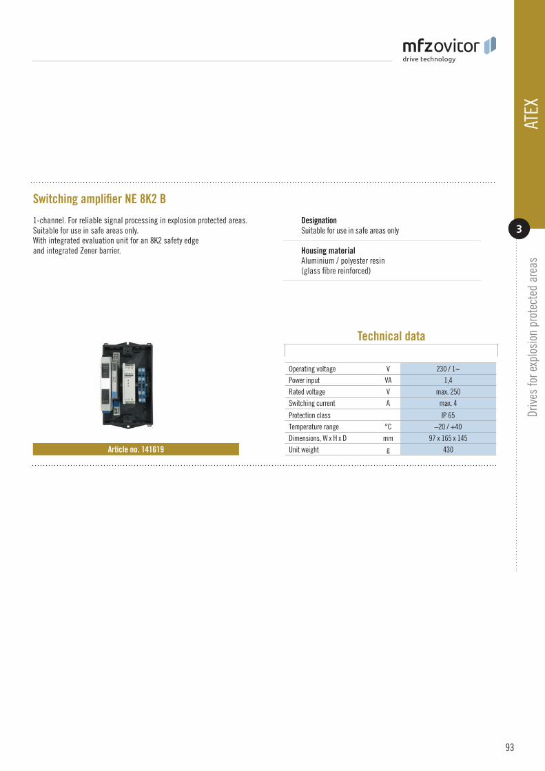
Technical data
93
ATEX
3
Driv
es fo
r exp
losi
on p
rote
cted
are
as
Operating voltage V 230 / 1~Power input VA 1,4Rated voltage V max. 250Switching current A max. 4
Protection class IP 65Temperature range °C –20 / +40Dimensions, W x H x D mm 97 x 165 x 145Unit weight g 430
DesignationSuitable for use in safe areas only
Housing material Aluminium / polyester resin (glass fibre reinforced)
Switching amplifier NE 8K2 B
1-channel. For reliable signal processing in explosion protected areas. Suitable for use in safe areas only. With integrated evaluation unit for an 8K2 safety edge and integrated Zener barrier.
Article no. 141619

94
for door systems in explosion protected areas
SWITCHING AMPLIFIERS
Article no. 89590
Article no. 141669
Technical data
Technical data
www.mfz-antriebe.de
ATEX
Driv
es fo
r exp
losi
on p
rote
cted
are
as
3DesignationEx II 2G Ex ed IIC T6 Ex II 2D Ex tD A21 IP66 T80ºC
Test certificatePTB 01 ATEX 1105
Housing material Polyester resin (glass fibre reinforced)
Explosion protection 3-button input unit
Suitable for use in zones 1 and 2, as well as 21 and 22.
DesignationEx II 2G Ex ed IIC T6 Ex II 2D Ex tD A21 IP66 T80ºC
Test certificatePTB 01 ATEX 1024
Housing material Polyester resin (glass fibre reinforced)
Explosion protection mains isolator switch
4-pin. Protected against inadvertent switching on. Suitable for use in zones 1 and 2, as well as 21 and 22.
Rated voltage V-AC max. 690Switching current A max. 16Protection class IP 66Temperature range °C –20 / +40
Dimensions, W x H x D mm 115 x 170 x 130Unit weight g 1250
Rated voltage V-AC max. 400Switching current A max. 6Protection class IP 66Temperature range °C –20 / +40
Dimensions, W x H x D mm 80 x 185 x 72Unit weight g 660

Technical data
Technical data
95
ATEX
3
Driv
es fo
r exp
losi
on p
rote
cted
are
as
Rated voltage V-AC max. 550Protection class IP 66Temperature range °C –20 / +40Dimensions, W x H x D mm 160 x 160 x 90
Unit weight g 1500
DesignationEx II 2G Ex e IIC T6 Gb Ex II 2D Ex tb IIIC T80ºC Db
Test certificate PTB 08 ATEX 1064
Housing material Polyester resin (glass fibre reinforced)
Explosion protection terminal box Ex e
With cable lead-ins for 4 limit switches. Suitable for use in zones 1 and 2, as well as 21 and 22.
Article no. 121476
Rated voltage V-AC max. 550Protection class IP 66Temperature range °C –20 / +40Dimensions, W x H x D mm 160 x 160 x 90
Unit weight g 1500
DesignationEx II 2G Ex e IIC T6 Gb Ex II 2D Ex tb IIIC T80ºC Db
Test certificate PTB 08 ATEX 1064
Housing material Polyester resin (glass fibre reinforced)
Explosion protection terminal box Ex e
With cable lead-ins for 6 limit switches. Suitable for use in zones 1 and 2, as well as 21 and 22.
Article no. 118585

96
for door systems in explosion protected areas
ACCESSORIES
Article no. 141705
Technical data
Technical data
www.mfz-antriebe.de
ATEX
Driv
es fo
r exp
losi
on p
rote
cted
are
as
3Reflection photoelectric barrier in housing consisting of transmitter/ receiver, mirror and switching amplifier in a separate housing. Suitable for use in zones 1 and 2. (Switching amplifier in safe area)
Explosion protection photoelectric barrier, reflection
DesignationEx II 2G Ex ia IIC T4
Test certificatePTB 03 ATEX 2104
Housing material Steel
Switching amplifiers
DesignationSuitable for use in safe areas only
Housing material Polycarbonate (glass fibre reinforced)
Explosion protection photoelectric barrier, reflection
Supply voltage V-ACV-DC
230 24
Power input VA 4,4Rated voltage V max. 250Switching current A max. 5
Protection class (with housing) IP 65Temperature range °C –20 / +40Dimensions, W x H x D mm 97 x 165 x 145Unit weight g 430
Supply voltage via switching amplifier
V-DC 8,2
Range m max. 8Protection class IP 67Temperature range °C –20 / +40
Dimensions, W x H x D mm 97 x 100 x 65Unit weight g 350

01
03
04
02
05
06
07
08
09
10
Drive for use in explosion protected rooms.With 4 or 6 encapsulated limit switches and anencapsulated micro switch for polling emergency operation.
2 cables for encapsulated limit switches. Firmly attached to the drive and always included in the package contents. Thecable length is 3 metres.
Cable for encapsulated micro switch. Firmly attached to the drive and always included in the package contents. The cable length is 3 metres.
Terminal box. Serves as connection point between the drive and control unit. Must always be ordered at the same time.
Control in various versions and with a varietyof different functions. Always supplied without 3-button input unit, provided the control unit is instal-led directly in the explosion protected area.
Separate 3-button input unit for installation in explosion protected areas. Must always be ordered at the same time, even if the control unit is installed in the explosion protected area.
Motor connection cable*
Connecting cable terminal box / control unit*
Connecting cable 3-button input unit / control unit*
Power cable to control unit*
03 07
04
01
02
05
06
1009
08
97
ATEX
3
Driv
es fo
r exp
losi
on p
rote
cted
are
as
Useful system components
The following minimum components are required for a door or gate system in explosion protected rooms:
* Not included in the package contents Items 7-10 must be selected, procured and configured by the installer. These items cannot be obtained from MFZ.

MFZ Antriebe GmbH & Co. KGNeue Mühle 4D-48739 Legden, Germany
www.mfz-antriebe.de 03/
2018
/EN

SERVICE.
DIVERSITY.
QUALITY.
INDIVIDUAL SOLUTIONS.
THIS IS WHAT
DRIVES US.
2018
www.mfz-antriebe.de

CONTROLSwww.mfz-antriebe.de

1
Controls for industrial doors Starting on page 132
CS
2
3
Controls for dock levellersStarting on page 142
Uninterruptible power supplyStarting on page 146
RS
UPS
Section on controls
CONTROLS
131

CONTROLSThe MFZ range of controls
The MFZ range of controls covers the entire range of applications demanded by the market for roller shutters, sectional doors and high-speed doors. The product portfolio ranges from relay controls to underground garage controls with traffic light function to complex door controls with an integrated frequency converter and controls for dock levellers. In addition, our specialist catalogues contain further special-purpose controls for use with fire-proof doors, in explosion-protected rooms, for pool covers and sliding gates.
CS 255 AC Basic automatic control for sectional doors
CS 310 Comfort automatic control for industrial doorsCS 310 IE Underground garage applicationCS 310 FU Integrated frequency converter controlCS 310 FS Fire protection control
for standard roller shutter and sectional door drives
RS 200 Basic control for dock levellersRS 200 L with integrated overload protectionRS 200 D with integrated direction checkingRS 200 + with integrated CS 310 door control
RS 300 Comfort control for dock levellersRS 300 K Swing lip / 1-2 valvesRS 300 V Telescoping lip / 2-3 valvesRS 300 + with integrated CS 310 door control
Integrated cover hinges, can be installed on 3 sides
Plug-in connections
Adjustable, pre-assembled wall brackets
Connection cables can be fed throughbetween the housing and wall
Components protected by plastic cover (CS 310 only)
BUS modules for function expansion (CS 310 only)
Integrated cooling element on the rear (for frequency converter operation)
Individual cover membranes
Pluggable cable looms with different lengths(Section 12 “Accessories”)
Characteristics
01
05
02
03
04
06
07
08
09
CS 255 AC CS 310 RS 200 RS 300
www.mfz-antriebe.de
132

08
Cont
rols
1
06
03 04
09
01
1
CONTROLS
07
02
133
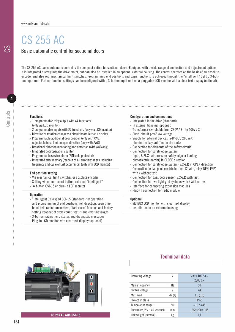
134
Basic automatic control for sectional doors
CS 255 AC
CS 255 AC with CSI-15
The CS 255 AC basic automatic control is the compact option for sectional doors. Equipped with a wide range of connection and adjustment options, it is integrated directly into the drive motor, but can also be installed in an optional external housing. The control operates on the basis of an absolute encoder and also with mechanical limit switches. Programming end positions and basic functions is achieved through the “intelligent” CSI 15 3-but-ton input unit. Further function settings can be configured with a 3-button input unit on a pluggable LCD monitor with a clear text display (optional).
Operating voltage V 230 / 400 / 3~230 / 1~
Mains frequency Hz 50Control voltage V 24
Max. load kW (A) 1.5 (5.0)Protection class IP 65Temperature range °C –10 / +45Dimensions, W x H x D (external) mm 165 x 220 x 105Unit weight (external) kg 1,1
Technical data
Functions· 1 programmable relay output with 44 functions (only via LCD monitor)· 2 programmable inputs with 27 functions (only via LCD monitor)· Direction of rotation change via circuit board button / display· Programmable additional door position (only with AWG)· Adjustable force limit in open direction (only with AWG)· Rotational direction monitoring and detection (with AWG only)· Integrated door operation counter· Programmable service alarm (PIN code protected)· Integrated error memory (readout of all error messages including frequency and cycle of last occurrence) (only with LCD monitor)
End position setting · Via mechanical limit switches or absolute encoder· Setting via circuit board button, external “intelligent”· 3x button CSI-15 or plug-in LCD monitor
Operation · ”Intelligent 3x keypad CSI-15 (standard) for operation and programming of end positions, roll direction, open time, hand-held radio transmitters, “fast close” function and factory setting Readout of cycle count, status and error messages· 3-button navigation / status and diagnostic messages· Plug-in LCD monitor with clear text display (optional)
Configuration and connections· Integrated in the drive (standard)· In external housing (optional)· Transformer switchable from 230V / 3~ to 400V / 3~· Short-circuit proof low voltage· Supply for external devices (24V-DC / 200 mA)· Illuminated keypad (find in the dark)· Connection for elements of the safety circuit· Connection for safety edge system (opto, 8.2kΩ, air pressure safety edge or leading photoelectric barrier) in CLOSE direction· Connection for safety edge system (8.2kΩ) in OPEN direction· Connection for two photoelectric barriers (2-wire, relay, NPN, PNP) with / without test· Connection for pass door sensor (8.2kΩ) with test· Connection for two light grid systems with / without test· Interface for connecting expansion modules· Plug-in connection for radio module
Optional· MS BUS LCD monitor with clear text display· Installation in an external housing
CSCo
ntro
ls
1
www.mfz-antriebe.de

135
CSCo
ntro
ls
1
Comfort automatic control for roller shutters and sectional doors
CS 310
The CS 310 comfort control is a special development for roller shutters, sectional doors, and sliding doors and gates, and is ideally adjusted to meet the requirements of these types of use. The fully equipped microprocessor control is based on the proven concept of the CS 300 and can be activated through an absolute encoder and also through mechanical limit switches. With numerous connection and extension options, even complex control tasks are child’s play for the CS 310. For new installations, but also for safely upgrading existing door and gate systems.
Operating voltage V 230 / 400 / 3~230 / 1~
Mains frequency Hz 50 / 60Control voltage V 24
Max. load kW (A) 2.2 (8.0)Protection class IP 65Temperature range °C –10 / +45Dimensions, W x H x D (external) mm 215 x 275 x 190Unit weight (external) kg 1,8
Technical data
Functions· 4 programmable relay outputs with 44 functions· 2 programmable inputs with 27 functions· Direction of rotation change via circuit board button / display· Programmable additional door position (only with AWG)· Adjustable force limit in open direction (only with AWG)· Rotational direction monitoring and detection (with AWG only)· Integrated door operation counter· Programmable service alarm (PIN code protected)· Integrated error memory (readout of all error messages including frequency and cycle of last occurrence) (only with LCD monitor)
End position setting · Via mechanical limit switches or absolute encoder· Setting via circuit board button or plug-in LCD monitor
Operation · Buttons on the main board and LEDs for status message (standard)· Plug-in LCD monitor with clear text display (optional)· 3-button navigation / status and diagnostic messages
Configuration and connections· Transformer switchable from 230V / 3~ to 400V / 3~· Short-circuit proof low voltage· Supply for external devices (24V-DC / 500 mA and 230V-AC / 1A)· Illuminated buttons (find in the dark)· Protective housing for the circuit board· Adjustable, pre-assembled wall brackets· Connection for elements of the safety circuit· Connection for safety edge system (opto, 8.2kΩ, air pressure safety edge or leading photoelectric barrier) in CLOSE direction· Connection for safety edge system (8.2kΩ) in OPEN direction· Connection for two photoelectric barriers (2-wire, relay, NPN, PNP) with / without test· Connection for pass door sensor (8.2kΩ) with test· Connection for two light grid systems with / without test· Interface for connecting a frequency converter· Interface for connecting expansion modules· Plug-in connections for radio module and weekly timer· Plug-in connection for radio transmission module, 2-channel. · For wireless signal transmission of closing edge safety device and / or safety circuit
Optional · LCD monitor with clear text display · MS-BUS expansion module for two-way traffic control, page 137· MS BUS draw-in protection expansion module, page 137· Integrated main switch· Individual cover membranes
CS 310
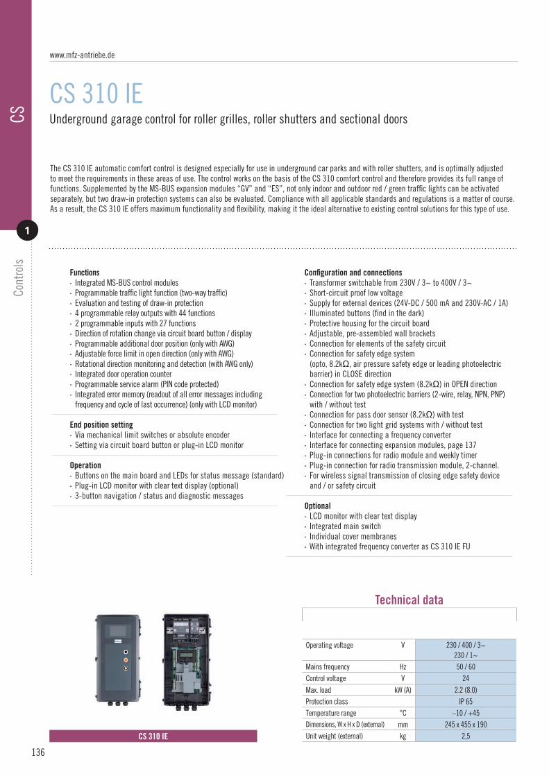
136
Underground garage control for roller grilles, roller shutters and sectional doors
CS 310 IE
CS 310 IE
The CS 310 IE automatic comfort control is designed especially for use in underground car parks and with roller shutters, and is optimally adjusted to meet the requirements in these areas of use. The control works on the basis of the CS 310 comfort control and therefore provides its full range of functions. Supplemented by the MS-BUS expansion modules “GV” and “ES”, not only indoor and outdoor red / green traffic lights can be activated separately, but two draw-in protection systems can also be evaluated. Compliance with all applicable standards and regulations is a matter of course. As a result, the CS 310 IE offers maximum functionality and flexibility, making it the ideal alternative to existing control solutions for this type of use.
Operating voltage V 230 / 400 / 3~230 / 1~
Mains frequency Hz 50 / 60Control voltage V 24
Max. load kW (A) 2.2 (8.0)Protection class IP 65Temperature range °C –10 / +45Dimensions, W x H x D (external) mm 245 x 455 x 190Unit weight (external) kg 2,5
Technical data
Functions· Integrated MS-BUS control modules· Programmable traffic light function (two-way traffic)· Evaluation and testing of draw-in protection· 4 programmable relay outputs with 44 functions· 2 programmable inputs with 27 functions· Direction of rotation change via circuit board button / display· Programmable additional door position (only with AWG)· Adjustable force limit in open direction (only with AWG)· Rotational direction monitoring and detection (with AWG only)· Integrated door operation counter· Programmable service alarm (PIN code protected)· Integrated error memory (readout of all error messages including frequency and cycle of last occurrence) (only with LCD monitor)
End position setting · Via mechanical limit switches or absolute encoder· Setting via circuit board button or plug-in LCD monitor
Operation · Buttons on the main board and LEDs for status message (standard)· Plug-in LCD monitor with clear text display (optional)· 3-button navigation / status and diagnostic messages
Configuration and connections· Transformer switchable from 230V / 3~ to 400V / 3~· Short-circuit proof low voltage· Supply for external devices (24V-DC / 500 mA and 230V-AC / 1A)· Illuminated buttons (find in the dark)· Protective housing for the circuit board· Adjustable, pre-assembled wall brackets· Connection for elements of the safety circuit· Connection for safety edge system (opto, 8.2kΩ, air pressure safety edge or leading photoelectric barrier) in CLOSE direction· Connection for safety edge system (8.2kΩ) in OPEN direction· Connection for two photoelectric barriers (2-wire, relay, NPN, PNP) with / without test· Connection for pass door sensor (8.2kΩ) with test· Connection for two light grid systems with / without test· Interface for connecting a frequency converter· Interface for connecting expansion modules, page 137· Plug-in connections for radio module and weekly timer· Plug-in connection for radio transmission module, 2-channel. · For wireless signal transmission of closing edge safety device and / or safety circuit
Optional · LCD monitor with clear text display· Integrated main switch· Individual cover membranes· With integrated frequency converter as CS 310 IE FU
CSCo
ntro
ls
1
www.mfz-antriebe.de

137
CSCo
ntro
ls
1
MS BUS expansion modules for draw-in protection, input / output expansion and two-way traffic control
MS BUS
MS BUS
With the MS BUS function modules, functions can be extended or additional functions implemented on the MFZ CS 255 or CS 310 controls. They are automatically detected and integrated after activation. Multiple modules can be connected and operated at the same time. The ES expansion module serves to connect and evaluate up to 2 draw-in protection systems. Such systems are specified by standards, for example on roller shutter systems or in hazard zones below 2.50 m. They prevent persons or objects from becoming entangled or crushed. The I/O expansion module provides the user with 4 additional programmable inputs and four additional programmable outputs. The GV expansion module is identical to the I/O module, but is supplied pre-programmed as a two-way traffic control to operate interior and exterior red / green traffic lights.
Protocol MS BUS MS BUSInterface RS-485 RS-485Operating voltage V 24 24
Max. load mA 20 500Power consumption mA 60 100Protection class IP 20 IP 20Temperature range °C –10 / +45 –10 / +45Dimensions, W x H x D mm 126 x 85 x 46 126 x 85 x 46
Unit weight g 150 250
Technical data
ES module characteristics· Connection of 1 or 2 draw-in protection systems (dynamic opto, PNP or relay)· Automatic detection of the connected system· Integrated draw-in protection testing· Activation in OPENING or CLOSING direction· Selectable supply voltage of the draw-in protection system (12 / 24V-DC)· Status and diagnostic messages via LED · For mounting on a cap rail· Includes MS BUS connection line (control)· Includes MS BUS connection line (module)
I/O module characteristics · Additional inputs and outputs· Up to 4 modules can be connected to the bus system· 4 programmable inputs with 21 functions· 4 programmable outputs with 44 functions· Status and diagnostic messages via LED· For mounting on a cap rail· Includes MS BUS connection line (control)· Includes MS BUS connection line (module)
GV module characteristics · Same as I / O expansion module, but pre-programmed as two-way traffic control
Output 1: Red traffic light, inside Output 2: Green traffic light, inside Output 3: Red traffic light, outside Output 4: Green traffic light, outside
Input 1: OPEN button, inside Input 2: OPEN button, outside Input 3: CLOSE button Input 4: CLOSE button
GV m
odule
ES m
odule
I/O m
odule

138
Comfort automatic control for roller shutters and sectional doors with integrated frequency converter
CS 310 FU
CS 310 FU-E CS 310 FU-I
The CS 310 FU is a comfort automatic control with an integrated frequency inverter. In this version, the standard CS 310 circuit boardis extended to include a frequency converter module and consequently allows speed-independent control of doors and gates. This not only ensures the best possible dynamics but also energy-efficient operation of the door or gate system. Two delivery versions are available:
CS 310 FU-E The frequency converter is integrated into the control housing.CS 310 FU-E The frequency converter is integrated into the drive.
Functions· Speed-independent control of doors · Separately adjustable beginning and end rotation speeds for both directions · Additional 2nd end speed adjustable in CLOSING direction · Acceleration and delay times adjustable for both directions · Acceleration and delay times for the activation of operating commands, stopping commands, safety edge protection and photocells are all separately adjustable · Braking points can be freely selected / adjustable brake delay · Adjustable output values for adaptation to the motor · 4 programmable relay outputs with 44 functions · 2 programmable inputs with 27 functions · Programmable additional door position · Rotational direction monitoring and detection (with AWG only) · Integrated door operation counter · Programmable service alarm (PIN code protected) · Integrated error memory (readout of all error messages including frequency and cycle of last occurrence) (only with LCD monitor)
End position setting · Via mechanical limit switches or absolute encoder· Setting via LCD monitor
Operation · Buttons on the main board and LEDs for status message (standard) · Plug-in LCD monitor with clear text display (optional) · 3-button navigation / status and diagnostic messages
Configuration and connections· Short-circuit proof low voltage · Supply for external devices (24V-DC / 500 mA and 230V-AC / 1A)· Illuminated buttons (find in the dark)· Protective housing for the circuit board· Adjustable, pre-assembled wall brackets· Connection for elements of the safety circuit· Connection for safety edge system (opto, 8.2kΩ, air pressure or leading photoelectric barrier) in CLOSE direction· Connection for safety edge system (8.2kΩ) in OPEN direction· Connection for two photoelectric barriers (2-wire, relay, NPN, PNP) with / without test· Connection for pass door sensor (8.2kΩ) with test· Connection for two light grid systems with / without test· Interface for connecting expansion modules· Plug-in connections for radio module and weekly timer· Plug-in connection for radio transmission module, 2-channel · For wireless signal transmission of closing edge safety device and / or safety circuit
Optional· MS-BUS expansion module for two-way traffic control, page 137· MS BUS draw-in protection expansion module, page 137· Integrated main switch· Individual cover membranes· Frequency converter integrated in the drive (version FU-I without brake, only 0.75 kW)
CSCo
ntro
ls
1
www.mfz-antriebe.de

Power setting 0.75 kW 0.75 kW 1.5 kW 1.5 kW 2.2 kW 3.0 kW 4.0 kWConfiguration FU-E FU-I FU-E FU-E FU-E FU-E FU-EOperating voltage V 230 / 1~ 230 / 1~ 230 / 1~ 400 / 3~ 400 / 3~ 400 / 3~ 400 / 3~
Motor output V 230 / 3~ 230 / 3~ 230 / 3~ 400 / 3~ 400 / 3~ 400 / 3~ 400 / 3~Mains frequency Hz 50 / 60 50 / 60 50 / 60 50 / 60 50 / 60 50 / 60 50 / 60Control voltage V 24 24 24 24 24 24 24Max. load kW (A) 0.75 (4.1) 0.75 (4.1) 1.5 (7.8) 1.5 (4.1) 2.2 (5.6) 3.0 (7.3) 4.0 (8.8)IP protection class 65 65 65 65 65 65 65
Temperature range °C –10 / +45 –10 / +45 –10 / +45 –10 / +45 –10 / +45 –10 / +45 -10 … +45
Housing Combination Standard Maxi Combination Combination Maxi Maxi
Dimensions, W x H x D mm 245 x 455 x 190 215 x 275 x 190 260 x 550 x 245 245 x 455 x 190 245 x 455 x 190 260 x 550 x 245 260 x 550 x 245
Unit weight kg 4,5 1,8 5,5 5,5 5,5 5,5 5,5
Technical data
139
CSCo
ntro
ls
1
The frequency converter components are available in these power settings. Additional power settings up to 7.5 kW / 400V / 3~ on request. The motor current, rather than the motor output, is the relevant parameter for selecting the correct frequency converter module.

140
Fire-proof control for standard roller shutter and sectional door drives
CS 310 FS
CS 310 FS
The CS 310 comfort automatic control unit is a universally compatible control system for industrial door drives. It can also be combined with standard roller shutter and sectional door drives and used in “fire-proof” applications. The system consists of a door drive, the CS 310 control unit and an unin-terruptible power supply (UPS). In case of a power failure, the UPS system is used for the one-time closing of a door system. The system is fully wired on delivery. Installation and commissioning are straightforward according to the plug & play principle. The control unit can be linked to a fire alarm system and features a programmable input that is compatible with all output types and features of the fire alarm system. With numerous connection and expansion possibilities, even complex control requirements can be readily met.
Normal operation. In normal operation, the CS 310 works as a standard door control unit with functioning safety devices. The motor is supplied directly with 400V / 3~. The door can be opened and closed.
Power failure · The motor is supplied by the UPS system. Now the gate system can only be closed.
Fire · An output of the fire alarm system can be linked to the CS 310 FS (NO or NC). Now the door can be closed (not opened) in case of fire. Directly when the mains supply is available, or via the UPS system in case of power failure.
· In both cases with active safety edge (stop only)
Functions· For standard roller shutter and sectional door drives· Closing via UPS system in case of power failure· Emergency closing via fire alarm contact with mains supply or UPS· All other functions same as CS 310, page 135
End position setting· Via mechanical limit switches or absolute encoder· Setting via circuit board button or plug-in LCD monitor
Operation· Buttons on the main board and LEDs for status message (standard)· Plug-in LCD monitor with clear text display (optional)· 3-button navigation / status and diagnostic messages
Configuration and connections· Straightforward commissioning according to plug & play principle· Connection of fire alarm contact· All other characteristics same as CS 310, page 135
Capacity· With fully charged batteries, 1 closing cycle can be guaranteed for a period of 24 hours
CSCo
ntro
ls
1
Operating voltage V 400 / 3~
Mains frequency Hz 50 / 60Control voltage V 24
Max. load kW (A) 2.2 (8.0)Protection class IP 65Temperature range °C –10 / +45Dimensions, W x H x D (external) mm 215 x 275 x 190Unit weight (external) kg 1,8
Technical data CS 310
www.mfz-antriebe.de
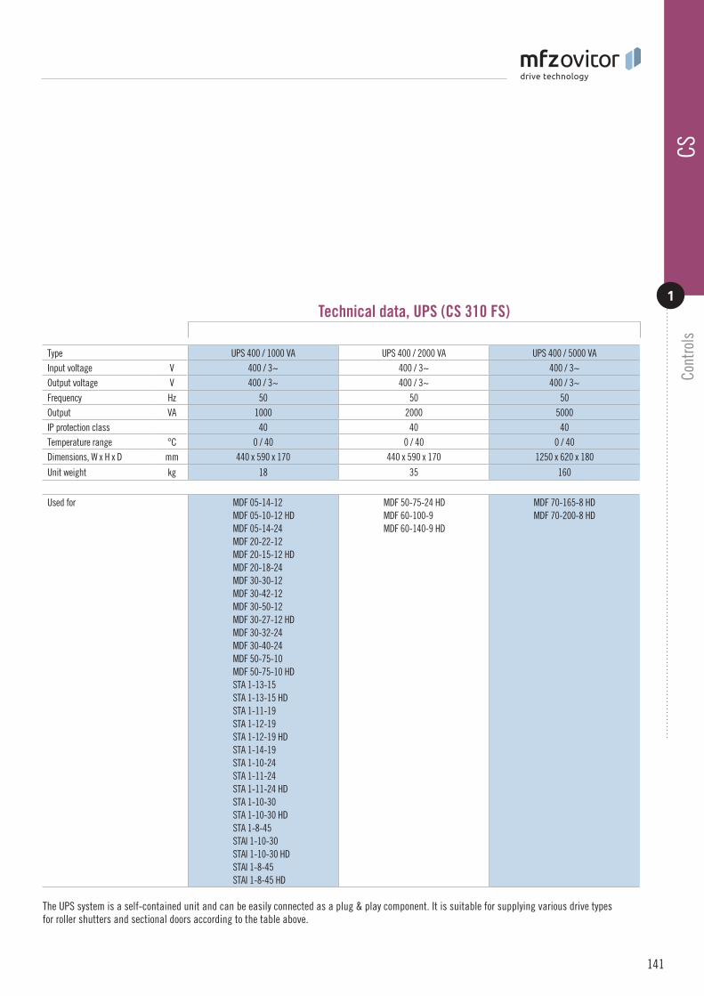
Type UPS 400 / 1000 VA UPS 400 / 2000 VA UPS 400 / 5000 VAInput voltage V 400 / 3~ 400 / 3~ 400 / 3~Output voltage V 400 / 3~ 400 / 3~ 400 / 3~
Frequency Hz 50 50 50Output VA 1000 2000 5000IP protection class 40 40 40Temperature range °C 0 / 40 0 / 40 0 / 40Dimensions, W x H x D mm 440 x 590 x 170 440 x 590 x 170 1250 x 620 x 180
Unit weight kg 18 35 160
Used for MDF 05-14-12MDF 05-10-12 HDMDF 05-14-24MDF 20-22-12MDF 20-15-12 HDMDF 20-18-24MDF 30-30-12MDF 30-42-12MDF 30-50-12MDF 30-27-12 HDMDF 30-32-24MDF 30-40-24MDF 50-75-10MDF 50-75-10 HDSTA 1-13-15STA 1-13-15 HDSTA 1-11-19STA 1-12-19STA 1-12-19 HDSTA 1-14-19STA 1-10-24STA 1-11-24STA 1-11-24 HDSTA 1-10-30STA 1-10-30 HDSTA 1-8-45STAI 1-10-30STAI 1-10-30 HDSTAI 1-8-45STAI 1-8-45 HD
MDF 50-75-24 HDMDF 60-100-9MDF 60-140-9 HD
MDF 70-165-8 HDMDF 70-200-8 HD
Technical data, UPS (CS 310 FS)
141
CSCo
ntro
ls
1
The UPS system is a self-contained unit and can be easily connected as a plug & play component. It is suitable for supplying various drive types for roller shutters and sectional doors according to the table above.

142
Basic control for dock levellers. Control of a swing lip.
RS 200
RS 200
The RS 200 basic control for dock levellers is intended exclusively for controlling dock levellers with a swing lip and valve. Although its range of func-tions is limited, the RS 200 in the standard version features a start interlock, phase failure detection and an interlocking option through an external door or gate control. Two delivery versions are available:
RS 200 L with integrated overload protectionRS 200 D with integrated direction checking
Operating voltage V 230 / 400 / 3~Mains frequency Hz 50 / 60Control voltage V 24
Max. load kW (A) 2.2 (6.3)Max. power consumption per valve mA 600Protection class IP 65Temperature range °C –10 / +55Dimensions, W x H x D (external) mm 215 x 275 x 190Unit weight (external) kg 2,5
Technical data
Functions· For controlling a dock leveller with swing lip· Operation of 1-valve units· Overload protection through current monitoring (RS 200 L)· Direction checking through voltage monitoring (RS 200 D)· Phase failure detection· Start-up interlocking after power failure· Release / interlocking through door or gate control
Operation · “Lift“ button on the circuit board· 1 red LED for status messages
Configuration and connections· Optionally, version L with overload protection · or version D with direction checking· Integrated main switch· Integrated fuses for the hydraulic unit (max 6.3 A)· Transformer switchable from 230V / 3~ to 400V / 3~· Short-circuit proof control voltage· Connection for an external “lift” button· Connection for the dock leveller interlock· Low housing base· Integrated cover hinges· Adjustable, pre-assembled wall brackets· Cable duct for connection cables
RSCo
ntro
ls
2
www.mfz-antriebe.de

143
RSCo
ntro
ls
2
Basic control for dock levellers with integrated door control. Control of a swing lip.
RS 200+
RS 200+
The RS 210 control is a combination of an RS 200 basic control for dock levellers and the CS 310 comfort control for door and gate systems. This combination offers the option of linking and centrally controlling the dock leveller and the door or gate. This allows the complex functions of the CS 310 to be implemented in addition to the straightforward range of functions of the RS 200 for dock levellers. Two delivery versions are available:
RS 200 L + CS 310 with integrated overload protectionRS 200 D + CS 310 with integrated direction checking
Functions· For controlling a dock leveller with swing lip· Operation of 1-valve units· Overload protection through current monitoring (RS 200 L)· Direction checking through voltage monitoring (RS 200 D)· Phase failure detection· Start-up interlocking after power failure· Release / interlocking through door or gate control· 4 programmable relay outputs with 44 functions· 2 programmable inputs with 27 functions· Direction of rotation change via circuit board button / display· Adjustable power limitation for both directions (with AWG only)· Rotational direction monitoring and detection (with AWG only)· Integrated door operation counter· Integrated error memory (readout of all error messages including frequency and cycle of last occurrence) (only with LCD monitor)
End position setting · Via mechanical limit switches or absolute encoder· Setting via circuit board button or plug-in LCD monitor
Operation · 1 direction button / 3-button input unit for door or gate control· Plug-in LCD monitor with clear text display· 3-button navigation / status and diagnostic messages
Configuration and connections · Integrated main switch· Integrated fuses for the hydraulic unit (max 6.3 A)· Transformer switchable from 230V / 3~ to 400V / 3~· Short-circuit proof control voltage· Supply for external devices (24V-DC / 500 mA and 230V-AC / 1A)· Illuminated buttons (find in the dark)· Connection for elements of the safety circuit· Connection for safety edge system (opto, 8.2kΩ, air pressure safety edge or leading photoelectric barrier) in CLOSE direction· Connection for two photoelectric barriers (2-wire, relay, NPN, PNP) with / without test· Connection for two light grid systems with / without test· Plug-in connection for radio transmission module, 2-channel. For wireless signal transmission of closing edge safety device and/or safety circuit
Optional · LCD monitor with clear text display· Individual cover membranes
Max. power consumption per valve V 230 / 400 / 3~Mains frequency Hz 50 / 60Control voltage V 24
Max. load RS 200 CS 310
kW (A)kW (A)
2.2 (6.3) 2.2 (8.0)
Max. power consumption per valve mA 600Protection class IP 65Temperature range °C –10 / +45Dimensions, W x H x D mm 245 x 455 x 190Unit weight kg 4,3
Technical data

144
Comfort control for dock levellers
RS 300
RS 300
The RS 300 comfort control for dock levellers is designed for activating dock levellers with a swing lip or telescopic lip. The range of functions is opti-mally adjusted to meet the requirements for this application and to offer the user a large number of connection options to solve even complex control tasks easily. Programming is achieved through the proven clear text display, and two delivery versions are available:
RS 300 K For controlling a dock leveller with a swing lip and 1 or 2 valves.RS 300 V For controlling a dock leveller with a telescoping lip and 2 or 3 valves.
Operating voltage V 230 / 400 / 3~Mains frequency Hz 50 / 60Control voltage V 24
Max. load kW (A) 2.2 (6.3)Max. power consumption per valve mA 600Protection class IP 65Temperature range °C –10 / +55Dimensions, W x H x D (external) mm 215 x 275 x 190Unit weight (external) kg 2,5
Technical data
Functions· RS 300 K: For controlling a dock leveller with swing lip Operation of 1 or 2-valve units· RS 300 V: For controlling a dock leveller with telescoping lip Operation of 2 or 3-valve units· Start-up interlocking after power failure· Phase failure detection· Direction checking through voltage monitoring· 1 programmable input with 4 functions· Activation of door or gate sealing (shelter function)· Release / interlocking through door or gate control· Release / interlocking of automatic door or gate system· Auto-return function· Cycle counter
Operation · 1 direction button (RS 300 K)· 3 direction buttons (RS 300 V)· Auto-return button· Plug-in LCD monitor with clear text display· Status and diagnostic messages
Configuration and connections· Integrated main switch· Integrated fuses for the hydraulic unit (max 6.3 A)· Short-circuit proof control voltage· Supply for external devices (24V-DC / 2500 mA)· Connection of indoor and outdoor traffic lights· Connection of wheel chock and start sensor· Connection of dock light or signal horn· Connection for emergency stop· Connection for the dock leveller interlock· Connection to interlock the door or gate system· All connections are pluggable· Low housing base· Integrated cover hinges· Adjustable, pre-assembled wall brackets· Cable duct for connection cables
Optional · Integrated 3x keypad for an external door or gate system· Button for forced lowering (RS300 V)· 4 or 2 direction buttons (RS300 V)
RSCo
ntro
ls
2
RS 300 K RS 300 V
www.mfz-antriebe.de

145
RSCo
ntro
ls
2
Comfort control for dock levellers with integrated door control
RS 300+
RS 300+
The RS 300+ control is a combination of the RS 300 comfort control for dock levellers and the CS 310 comfort control for door or gate systems. This combination offers the option of linking and centrally controlling the dock leveller and the door or gate. This provides a complex range of functions for the dock leveller and the door or gate that is optimally adjusted to the requirements in these areas of use. Programming is achieved through the proven clear text display, and two delivery versions are available:
RS 300 K + CS 310 For controlling a dock leveller with a swing lip and 1 or 2 valves.RS 300 V + CS 310 For controlling a dock leveller with a telescoping lip and 2 or 3 valves.
Functions· Version K: For controlling a dock leveller with hinged lip Operation of 1 or 2-valve units· Version V: For controlling a dock leveller with telescoping lip Operation of 2 or 3-valve units· Start-up interlocking after power failure· Direction checking / phase failure detection· 1 programmable input with 4 functions (dock)· Activation of door or gate sealing (shelter function)· Release / interlocking through door or gate control· Release / interlocking of automatic door or gate system· Integrated cycle counter / door operation counter· Auto-return function· 4 programmable relay outputs with 44 functions· 2 programmable inputs with 27 functions (door or gate)· Direction of rotation change via circuit board button / display· Adjustable power limitation for both directions (with AWG only)· Rotational direction monitoring and detection (with AWG only)· Integrated error memory (readout of all error messages including frequency and cycle of last occurrence) (only with LCD monitor)
End position setting · Via mechanical limit switches or absolute encoder· Setting via circuit board button or plug-in LCD monitor
Operation · 1 direction button (version K) / 3 direction buttons (version V)· 3-button input unit for door or gate control· Auto-return button· Plug-in LCD monitor with clear text display· 3-button navigation / status and diagnostic messages
Configuration and connections · Integrated main switch· Integrated fuses for the hydraulic unit (max 6.3 A)· Transformer switchable from 230V / 3~ to 400V / 3~· Short-circuit proof control voltage· Supply for external devices (24V-DC / 3000 mA and 230V-AC / 1A)· Connection of indoor and outdoor traffic lights· Connection of wheel chock and start sensor· Connection of dock light or signal horn· Connection for the dock leveller interlock· Connection to interlock the door or gate system· Connection for elements of the safety circuit
· Connection for safety edge system (opto, 8.2kΩ, air pressure safety edge or leading photoelectric barrier) in CLOSE direction
Optional · Button for forced lowering· 4 or 2 direction buttons (RS 300 V)· Control unit in steel cabinet
RS 300 operating voltage CS 310
VV
400 / 3~ 230 / 400 / 3~
Mains frequency Hz 50 / 60Control voltage V 24
Max. load RS 300 CS 310
kW (A)kW (A)
2.2 (6.3) 2.2 (8.0)
Max. power consumption per valve mA 800Protection class IP 65Temperature range °C –10 / +45Dimensions, W x H x D mm 260 x 550 x 245Unit weight kg 4,3
Technical data

146
Uninterruptible power supply for standard roller shutter and sectional door drives
UPS
UPS
The uninterruptible power supply (UPS) can be combined with standard roller shutter and sectional door drives, and serves as an autonomous energy supply. This makes it possible to open and close a door or gate system even in case of a power failure. The system as a compact unit in a metal housing consists of rechargeable batteries, including power and control electronics for fully automated control of switchingbetween mains and battery operation. Installation and commissioning are straightforward according to the plug & play principle.
Functions· When the mains supply fails, the UPS system is activated automatically and supplies the door control unit and drive.· As soon as the mains supply is restored, the door control unit and drive are supplied from the mains network again and the UPS batteries are charged.
Configuration and connections · Straightforward commissioning according to plug & play principle· For door or gate systems with 400V / 3~ supply voltage· UPS and door control are connected directly via CEE plug· No additional control line between UPS and door control· No use of internal relay outputs for switching between mains and UPS supply· No additional contactors for switching between mains and UPS supply· No additional settings on the door control unit or on the UPS
Capacity · With fully charged batteries, 1 door cyclus can be guaranteed for a period of 24 hours
UPS
Cont
rols
3
www.mfz-antriebe.de

Type UPS 400 / 750 VA UPS 400 / 1000 VA UPS 400 / 1500 VA UPS 400 / 5000 VA UPS 400 / 7500 VAInput voltage V 400 / 3~ 400 / 3~ 400 / 3~ 400 / 3~ 400 / 3~Output voltage V 400 / 3~ 400 / 3~ 400 / 3~ 400 / 3~ 400 / 3~
Frequency Hz 50 50 50 50 50Output VA 750 1000 1500 5000 7500IP protection class 40 40 40 40 40Temperature range °C 0 / 40 0 / 40 0 / 40 0 / 40 0 / 40Dimensions, W x H x D mm 440 x 590 x 170 440 x 590 x 170 440 x 590 x 170 1250 x 620 x 180 1250 x 620 x 180
Unit weight kg 15 18 24 160 180
Used for STA 1-5-24 STA 1-13-15STA 1-13-15 HDSTA 1-11-19STA 1-12-19STA 1-12-19 HDSTA 1-14-19STA 1-10-24STA 1-11-24STA 1-11-24 HDSTA 1-10-30STA 1-10-30 HDSTA 1-8-45STAI 1-10-30STAI 1-10-30 HDSTAI 1-8-45STAI 1-8-45 HDMTZ-S 05-4-45MTZ-S 05-4-90MTZ-S 05-4-115MTZ-S 05-4-135MTZ-S 20-7-65MTZ-S 20-7-90
MDF 05-14-12MDF 05-10-12 HDMDF 05-14-24MDF 20-22-12MDF 20-15-12 HDMDF 20-18-24DF 10-10-12DF 20-17-12KD 05-7-24KD 05-13-24KD 05-13-24 HDKD 20-22-24KD 20-22-24 HDMTZ-S 20-14-45MTZ-S 20-5-135
MDF 30-30-12MDF 30-42-12MDF 30-50-12MDF 30-27-12 HDMDF 30-32-18MDF 30-40-17MDF 30-32-24MDF 30-40-24MDF 50-75-10MDF 50-75-10 HDDF 30-30-12DF 40-40-10KD 30-30-24KD 30-30-24 HDKD 30-40-24KD 30-40-24 HDMTZ-S 30-16-45MTZ-S 30-14-70MTZ-S 30-14-90MTZ-S 30-20-90MTZ-S 30-13-120MTZ-S 30-10-150MTZ-S 50-27-52 HD
Technical data, UPS
147
UPS
Cont
rols
3
The UPS system is a self-contained unit and can be easily connected as a plug & play component. It is suitable for supplying various drive types for roller shutters and sectional doors according to the table above.

MFZ Antriebe GmbH & Co. KGNeue Mühle 4D-48739 Legden, Germany
www.mfz-antriebe.de 03/
2018
/EN
SERVICE.
DIVERSITY.
QUALITY.
INDIVIDUAL SOLUTIONS.
THIS IS WHAT
DRIVES US.
2018
www.mfz-antriebe.de

SAFETY SYSTEMS AND SENSORS
www.mfz-antriebe.de

1
Starting on page 152
SAFETY EDGE DEVICES
2
Starting on page 166
JUNCTION BOXES / SPIRAL CABLES
3
Starting on page 169
SAFETY SWITCHES
Section on safety systems and sensors
SAFETY SYSTEMS AND SENSORS
4
Starting on page 172
PHOTOELECTRIC BARRIERS
5
Starting on page 174
SPECIAL SENSORS
6
Starting on page 176
ACCESS CONTROL SYSTEMS
149

MFZ offer a suitable product range of safety systems, sensors and access control systems for all their drives. The products guarantee safety and protection for users and for their door or gate system. For long-term and safe operation of door and gate systems for industrial use.
SAFETY SYSTEMS AND SENSORS
Switches / photoelectric barriersSafety edge systems SensorsJunction boxes / spiral cables
Functional reliability
High-quality materials
Further safety systems on request
Special versions on request
Characteristics Overview
Safety systems
Transmission systems
Safety edge devices
Junction boxes
Spiral cables
Safety switches
Photoelectric barriers
Sensors
Special sensors
Access control systems
01
04
02
03
www.mfz-antriebe.de
150

Safe
ty s
yste
ms
and
sens
ors
SAFETY SYSTEMS AND SENSORS
151

152
for conventional connection or as pluggable solution
SIGNAL TRANSMISSION SYSTEM
Frequency, adjustable MHz 868 / 869Range m 10Temperature range °C –35 / +55
ReceiverOperating voltage V-DC 24Power input W 1,2IP protection class 55Dimensions (H x W x D) mm 81 x 121 x 46Weight g 130
TransmitterOperating voltage 1-channel (battery CR2032) 2-channel (battery AA)
V-DCV-DC
3 3,6
Power consumption mA 17IP protection class 67Dimensions (H x W x D) mm 51 x 183 x 36Weight g 130
Safe
ty s
yste
ms
and
sens
ors
· External transmitter / receiver· PL c, cat. 2 according to DIN EN 13849-2
· 1-channel set· for transmission of a safety circuit or an electronic closing edge safety device (8.2kΩ) · Article no. 120939
· 2-channel set· for transmission of a safety circuit and an electronic (8.2 kΩ) or opto-electronic closing edge safety device · Article no. 123716
Transmitter supply via batteries(included in the package contents)
signal transmission system
Frequency, adjustable MHz 868 / 869Range m 10Temperature range °C –35 / +55
ReceiverPluggable circuit board for CS 310 control
TransmitterOperating voltage 1-channel (battery CR2032) 2-channel (battery AA)
V-DCV-DC
3 3,6
Power consumption mA 17IP protection class 67Dimensions (H x W x D) mm 51 x 183 x 36Weight g 130
· for MFZ control CS 310· PL c, cat. 2 according to DIN EN 13849-2
· 1-channel set· for transmission of a safety circuit or an electronic closing edge safety device (8.2kΩ) · Article no. 140141
· 2-channel set· for transmission of a safety circuit and an electronic (8.2 kΩ) or opto-electronic closing edge safety device · Article no. 123717
Transmitter supply via batteries(included in the package contents)
Signal transmission system, pluggable
Technical data
Technical data
www.mfz-antriebe.de
SAFE
TY E
DGE
DEVI
CES
1
Set consisting of transmitter and receiver. For wireless evaluation of a closing edge safety device and/or a safety circuit.External transmitter as 1-channel or 2-channel version.Conventional connection: external 2-channel receiver.Pluggable solution: 2-channel receiver as pluggable version for CS 310 control unit.

· for signal transmission system· PL c, cat. 2 according to DIN EN 13849-2 · Article no. 160329
Only in combination with thesignal transmission system
Supply via 1 x CR3032(included in the package contents)
Pass door sensor, wireless
Frequency, adjustable MHz 868 / 869Range m 10IP protection class 55Height mm 64Width mm 41Depth mm 13Weight g 25
Technical data
SAFE
TY E
DGE
DEVI
CES
1
Safe
ty s
yste
ms
and
sens
ors
153

154
for conventional connection or as pluggable solution
OPTO-SENSOR SYSTEM
Safe
ty s
yste
ms
and
sens
ors
Temperature range °C –20 / +55IP protection class 68Transmitter cable length m 10,5Receiver cable length m 1,0Weight g 200
F photoelectric barrier, transmitter / receiver
· With diagnosis LED for status recognition· Incl. F sleeve 11 / 22 mm
F photoelectric barrier, pluggable transmitter
F photoelectric barrier, pluggable receiver
· With diagnosis LED for status recognition· Incl. 2 x F sleeve 11 / 22 mm · Article no. 160264
· Incl. F sleeve 11 / 22 mm
Temperature range °C –20 / +55IP protection class 68Weight (0.4 / 4.0 / 6.0 / 10.5 m) g 30 / 90 / 110 / 150
Temperature range °C –20 / +55IP protection class 68Weight g 30
Cable length 0.4 m Article no. 163195Cable length 4.0 m Article no. 163194Cable length 6.0 m Article no. 160486Cable length 10.5 m Article no. 160157
Cable length 0.4 m Article no. 119200
Technical data
Technical data
Technical data
www.mfz-antriebe.de
SAFE
TY E
DGE
DEVI
CES
1
The components for conventional connection can be connected directly to the terminal clamps of the control unit. The pluggable components can be connected directly to the circuit board of the door leaf junction box. The door leaf junction box is mounted on the door leaf and connected to the door control unit by a spiral cable. (Door leaf junction box and spiral cable, see pages 166 f.)

External diameter mm 14Internal diameter mm 11Length mm 30Weight g 10Packing unit 2
F sleeve
· 11 / 22 mm · Article no. 79834
F sleeve
F aluminium profile
· 11 / 14 mm · Article no. 119318
· For F profile P1, P2, P4, P6 · Article no. 102682 Weight per running metre g 200
max. piece length m 2
External diameter mm 22Internal diameter mm 11Length mm 30Weight g 10Packing unit 2
919,5
2,55,
590
ø10,9
0,9
19,5
2,5
5,5
2
25
3,5
37,3
74,5
ø10,9
2,97
9,515,619,824,5
2,5
5,5
2,5
2
0,95ø10,9
35
9,519,8
2,55,
5
2
521,
85
ø21
75,2
5
Profil OSE P425
18
62
25
9
72
Profil OSE P1
Profil OSE P2
Profil OSE P6
ø 20
1,5
(39,65)
17
52°
2,1
3,5
35,8
40°
17
50°
Profil OSE P9
AluminiumC - Profile
f¸r G-Profil
f¸r DW-Profil
f¸r F-Profil
24,5
2
5
17,5
28,5
Druckwellenprofil
924
,5
2
5
15,5
28,5
924
,52
5
15,5
28-3
0
68
17,530
4,
5
28,5
17
14
44
25
15,525
28,5
1443
4,5
8
17,525
Profil SKS 8,2KOhm
001.02
Profil SKS 8,2KOhm
005.02
Profil SKS 8,2KOhm003.10
Profil SKS 8,2KOhm
008.02
Profil SKS 8,2KOhm
016.10
924
,5
28,5
Profil SKS 8,2KOhm
001.01
8,5
4,5 15,5
Technical data
Technical data
Technical data
SAFE
TY E
DGE
DEVI
CES
1
Safe
ty s
yste
ms
and
sens
ors
155

156
Profiles and stop buffers
OPTO-SENSOR SYSTEM
Safe
ty s
yste
ms
and
sens
ors
Weight per running metre g 200Roll length m 50
F profile P1
F profile P2
F profile P4
F profile P6
Weight per running metre g 700Roll length m 25
Weight per running metre g 900Roll length m 25
Weight per running metre g 1200Roll length m 25
919,5
2,55,
590
ø10,9
0,9
19,5
2,5
5,5
2
25
3,5
37,3
74,5
ø10,9
2,97
9,515,619,824,5
2,5
5,5
2,5
2
0,95ø10,9
35
9,519,8
2,55,
5
2
521,
85
ø21
75,2
5
Profil OSE P425
18
62
25
9
72
Profil OSE P1
Profil OSE P2
Profil OSE P6
ø 20
1,5
(39,65)
17
52°
2,1
3,5
35,8
40°
17
50°
Profil OSE P9
AluminiumC - Profile
f¸r G-Profil
f¸r DW-Profil
f¸r F-Profil
24,5
2
5
17,5
28,5
Druckwellenprofil
924
,5
2
5
15,5
28,5
924
,52
5
15,5
28-3
0
68
17,530
4,
5
28,517
14
44
25
15,525
28,5
1443
4,5
8
17,525
Profil SKS 8,2KOhm
001.02
Profil SKS 8,2KOhm
005.02
Profil SKS 8,2KOhm003.10
Profil SKS 8,2KOhm
008.02
Profil SKS 8,2KOhm
016.10
924
,5
28,5
Profil SKS 8,2KOhm
001.01
8,5
4,5 15,5
919,5
2,55,
590
ø10,9
0,9
19,5
2,5
5,5
2
25
3,5
37,3
74,5
ø10,9
2,97
9,515,619,824,5
2,5
5,5
2,5
2
0,95ø10,9
35
9,519,8
2,55,
5
2
521,
85
ø21
75,2
5
Profil OSE P425
18
62
25
9
72
Profil OSE P1
Profil OSE P2
Profil OSE P6
ø 20
1,5
(39,65)
17
52°
2,1
3,5
35,8
40°
17
50°
Profil OSE P9
AluminiumC - Profile
f¸r G-Profil
f¸r DW-Profil
f¸r F-Profil
24,5
2
5
17,5
28,5
Druckwellenprofil
924
,5
2
5
15,5
28,5
924
,52
5
15,5
28-3
0
68
17,530
4,
5
28,5
17
14
44
25
15,525
28,5
1443
4,5
8
17,525
Profil SKS 8,2KOhm
001.02
Profil SKS 8,2KOhm
005.02
Profil SKS 8,2KOhm003.10
Profil SKS 8,2KOhm
008.02
Profil SKS 8,2KOhm
016.109
24,5
28,5
Profil SKS 8,2KOhm
001.01
8,5
4,5 15,5
919,5
2,55,
590
ø10,9
0,9
19,5
2,5
5,5
2
25
3,5
37,3
74,5
ø10,9
2,97
9,515,619,824,5
2,5
5,5
2,5
2
0,95ø10,9
35
9,519,8
2,55,
5
2
521,
85
ø21
75,2
5
Profil OSE P425
18
62
25
9
72
Profil OSE P1
Profil OSE P2
Profil OSE P6
ø 20
1,5
(39,65)
17
52°
2,1
3,5
35,8
40°
17
50°
Profil OSE P9
AluminiumC - Profile
f¸r G-Profil
f¸r DW-Profil
f¸r F-Profil
24,5
2
5
17,5
28,5
Druckwellenprofil
924
,5
2
5
15,5
28,5
924
,52
5
15,5
28-3
0
68
17,530
4,
5
28,5
17
14
44
25
15,525
28,5
1443
4,5
8
17,525
Profil SKS 8,2KOhm
001.02
Profil SKS 8,2KOhm
005.02
Profil SKS 8,2KOhm003.10
Profil SKS 8,2KOhm
008.02
Profil SKS 8,2KOhm
016.10
924
,528,5
Profil SKS 8,2KOhm
001.01
8,5
4,5 15,5
Technical data
· Article no. 121454
· Article no. 114678
· Article no. 114677
· Article no. 115811
Technical data
Technical data
Technical data
919,5
2,55,
590
ø10,9
0,9
19,5
2,5
5,5
2
25
3,5
37,3
74,5
ø10,9
2,97
9,515,619,824,5
2,5
5,5
2,5
2
0,95ø10,9
35
9,519,8
2,55,
5
2
521,
85
ø21
75,2
5
Profil OSE P425
18
62
25
9
72
Profil OSE P1
Profil OSE P2
Profil OSE P6
ø 20
1,5
(39,65)
17
52°
2,1
3,5
35,8
40°
17
50°
Profil OSE P9
AluminiumC - Profile
f¸r G-Profil
f¸r DW-Profil
f¸r F-Profil
24,5
2
5
17,5
28,5
Druckwellenprofil
924
,5
2
5
15,5
28,5
924
,52
5
15,5
28-3
0
68
17,530
4,
5
28,5
17
14
44
25
15,525
28,5
1443
4,5
8
17,525
Profil SKS 8,2KOhm
001.02
Profil SKS 8,2KOhm
005.02
Profil SKS 8,2KOhm003.10
Profil SKS 8,2KOhm
008.02
Profil SKS 8,2KOhm
016.10
924
,5
28,5
Profil SKS 8,2KOhm
001.01
8,5
4,5 15,5
www.mfz-antriebe.de
SAFE
TY E
DGE
DEVI
CES
1
To ensure long-term reliability and performance of the system, it is essential that appropriate stop buffers are fitted in addition to the profiles.

Height mm 25Width mm 18Depth mm 30Weight g 25Packing unit 2
F stop buffer 1
F stop buffer 2
F stop buffer 3
Height mm 55Width mm 18Depth mm 30Weight g 40Packing unit 2
Height mm 45Width mm 25Depth mm 45Weight g 50
· For F profile P2, P4 · Article no. 100893
· For F profile P1 · Article no. 156609
· For F profile P2, P4 · Article no. 122954
Technical data
Technical data
Technical data
SAFE
TY E
DGE
DEVI
CES
1
Safe
ty s
yste
ms
and
sens
ors
157

158
with 8.2 kΩ terminating resistor
ELECTRIC CONTACT BAR
Safe
ty s
yste
ms
and
sens
ors
A plug 25.30
A plug 25.45
Aluminium profile
A end plug
A profileA plug
· For A profile 25.30 TT and 25.30 TTLa Incl. clamping piece, end cap and mounting clip
· For A profile 25.45 TT and 25.45 TTLa Incl. clamping piece, end cap and mounting clips
Height mm 31Width mm 28Depth mm 17Weight 0.3 / 1.0 / 2.5 / 5.0 / 10.0 m g 30 / 50 / 125 / 190 / 355
Height mm 46Width mm 28Depth mm 17Weight 0.3 / 1.0 / 2.5 / 5.0 / 10.0 m g 35 / 55 / 130 / 195 / 360
Cable length 0.3 m Article no. 149793Cable length 1.0 m Article no. 149935Cable length 2.5 m Article no. 149792Cable length 5.0 m Article no. 149936Cable length 10.0 m Article no. 150219
Cable length 0.3 m Article no. 149789Cable length 1.0 m Article no. 149933Cable length 2.5 m Article no. 123147Cable length 5.0 m Article no. 149934Cable length 10.0 m Article no. 151262
Technical data
Technical data
www.mfz-antriebe.de
SAFE
TY E
DGE
DEVI
CES
1
To ensure long-term reliability and performance of the system, it is essential that appropriate stop buffers are fitted in addition to the profiles.
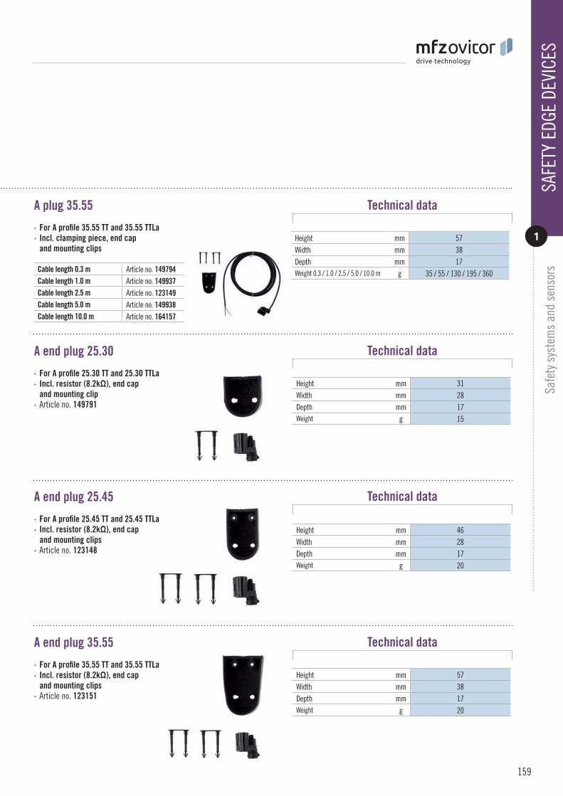
A plug 35.55
A end plug 25.30
A end plug 25.45
A end plug 35.55
· For A profile 25.45 TT and 25.45 TTLa· Incl. resistor (8.2kΩ), end cap and mounting clips · Article no. 123148
· For A profile 35.55 TT and 35.55 TTLa· Incl. resistor (8.2kΩ), end cap and mounting clips · Article no. 123151
· For A profile 25.30 TT and 25.30 TTLa· Incl. resistor (8.2kΩ), end cap and mounting clip · Article no. 149791
· For A profile 35.55 TT and 35.55 TTLa· Incl. clamping piece, end cap and mounting clips
Height mm 57Width mm 38Depth mm 17Weight 0.3 / 1.0 / 2.5 / 5.0 / 10.0 m g 35 / 55 / 130 / 195 / 360
Height mm 31Width mm 28Depth mm 17Weight g 15
Height mm 46Width mm 28Depth mm 17Weight g 20
Height mm 57Width mm 38Depth mm 17Weight g 20
Cable length 0.3 m Article no. 149794Cable length 1.0 m Article no. 149937Cable length 2.5 m Article no. 123149Cable length 5.0 m Article no. 149938Cable length 10.0 m Article no. 164157
Technical data
Technical data
Technical data
Technical data
SAFE
TY E
DGE
DEVI
CES
1
Safe
ty s
yste
ms
and
sens
ors
159
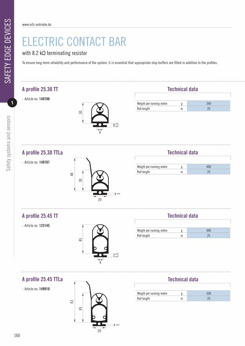
160
with 8.2 kΩ terminating resistor
ELECTRIC CONTACT BAR
Safe
ty s
yste
ms
and
sens
ors
A profile 25.30 TT
A profile 25.30 TTLa
A profile 25.45 TT
A profile 25.45 TTLa
Weight per running metre g 340Roll length m 25
Weight per running metre g 400Roll length m 25
Weight per running metre g 440Roll length m 25
Weight per running metre g 500Roll length m 25
· Article no. 149788
· Article no. 149787
· Article no. 123145
· Article no. 149910
Technical data
Technical data
Technical data
Technical data
5,5
9
30
3
30
48
20
45
9
5,5
45
20
63
3
www.mfz-antriebe.de
SAFE
TY E
DGE
DEVI
CES
1
To ensure long-term reliability and performance of the system, it is essential that appropriate stop buffers are fitted in addition to the profiles.

A profile 35.55 TT
A profile 35.55 TTLa
Weight per running metre g 610Roll length m 25
Weight per running metre g 650Roll length m 25
· Article no. 149869
· Article no. 123146
Technical data
Technical data
29
3
55
5,5
9,5
71,5
55
SAFE
TY E
DGE
DEVI
CES
1
Safe
ty s
yste
ms
and
sens
ors
161

162
with 8.2 kΩ terminating resistor
ELECTRIC CONTACT BAR
Safe
ty s
yste
ms
and
sens
ors
A stop buffer 1
A stop buffer 2
A stop buffer 3
· For A profile 25.45 · Article no. 123489
· For A profile 25.30 · Article no. 149868
· For A profile 35.55 · Article no. 123490
Height mm 27Width mm 35Depth mm 18Weight g 40Packing unit 2
Height mm 47Width mm 35Depth mm 18Weight g 50Packing unit 2
Height mm 55Width mm 18Depth mm 30Weight g 40Packing unit 2
Technical data
Technical data
Technical data
www.mfz-antriebe.de
SAFE
TY E
DGE
DEVI
CES
1
To ensure long-term reliability and performance of the system, it is essential that appropriate stop buffers are fitted in addition to the profiles.

Aluminium profile
Weight per running metre g 300max. piece length m 2
· For A profile 25.30 and 25.45 · Article no. 115798
919,5
2,55,
590
ø10,9
0,9
19,5
2,5
5,5
2
25
3,5
37,3
74,5
ø10,92,
97
9,515,619,824,5
2,5
5,5
2,5
2
0,95ø10,9
35
9,519,8
2,55,
5
2
521,
85
ø21
75,2
5
Profil OSE P425
1862
25
9
72
Profil OSE P1
Profil OSE P2
Profil OSE P6
ø 20
1,5
(39,65)
17
52°
2,1
3,5
35,8
40°
17
50°
Profil OSE P9
AluminiumC - Profile
f¸r G-Profil
f¸r DW-Profil
f¸r F-Profil
24,5
2
5
17,5
28,5
Druckwellenprofil
924
,5
2
5
15,5
28,5
924
,52
5
15,5
28-3
0
68
17,530
4,
5
28,5
17
14
44
25
15,525
28,5
1443
4,5
8
17,525
Profil SKS 8,2KOhm
001.02
Profil SKS 8,2KOhm
005.02
Profil SKS 8,2KOhm003.10
Profil SKS 8,2KOhm
008.02
Profil SKS 8,2KOhm
016.10
924
,5
28,5
Profil SKS 8,2KOhm
001.01
8,5
4,5 15,5
Technical data
SAFE
TY E
DGE
DEVI
CES
1
Safe
ty s
yste
ms
and
sens
ors
163

164
integrated into the pneumatic switch door leaf junction box
PNEUMATIC SWITCH
Safe
ty s
yste
ms
and
sens
ors
Pneumatic switch door leaf junction box
Pneumatic switch rubber profile
Pneumatic switch profile end plug
Aluminium profile
· Integrated pneumatic switch· Connections for safety components NC · Article no. 140487
Temperature range °C –20 / +60IP protection class 54Height mm 60Width mm 165Depth mm 40Weight g 100
Weight per running metre g 200Roll length m 50
External diameter mm 22Length mm 29Weight g 10Packing unit 1
Weight per running metre g 300max. piece length m 2
919,5
2,55,
590
ø10,9
0,9
19,5
2,5
5,5
2
25
3,5
37,3
74,5
ø10,9
2,97
9,515,619,824,5
2,5
5,5
2,5
2
0,95ø10,9
35
9,519,8
2,55,
5
2
521,
85
ø21
75,2
5
Profil OSE P425
18
62
25
9
72
Profil OSE P1
Profil OSE P2
Profil OSE P6
ø 20
1,5
(39,65)
17
52°
2,1
3,5
35,8
40°
17
50°
Profil OSE P9
AluminiumC - Profile
f¸r G-Profil
f¸r DW-Profil
f¸r F-Profil
24,5
2
5
17,5
28,5
Druckwellenprofil
924
,5
2
5
15,5
28,5
924
,52
5
15,5
28-3
0
68
17,530
4,
5
28,5
17
14
44
25
15,525
28,5
1443
4,5
8
17,525
Profil SKS 8,2KOhm
001.02
Profil SKS 8,2KOhm
005.02
Profil SKS 8,2KOhm003.10
Profil SKS 8,2KOhm
008.02
Profil SKS 8,2KOhm
016.10
924
,5
28,5
Profil SKS 8,2KOhm
001.01
8,5
4,5 15,5
Ø 21
9,5
17
2,5
2,5
24
2,5
· Article no. 122639
· Article no. 122638
· Article no. 115798
Technical data
Technical data
Technical data
Technical data
www.mfz-antriebe.de
SAFE
TY E
DGE
DEVI
CES
1

External diameter mm 4,5Internal diameter mm 2,5Weight per running metre g 200Roll length m 50
Pressure switch nipple
Pneumatic switch PVC hose
Profile end plug
Profile end plug
· 11 mm / 14 mm · Article no. 122640 Ø mm 10
Length mm 19Weight g 3
· Pneumatic hose, transparent · Article no. 151979
· Cone-shaped, 22 / 27 mm · Article no. 122636
· Cone-shaped, 28 / 34 mm · Article no. 143253 Ø mm 28 / 34
Length mm 35Weight g 65
Ø mm 22 / 27Length mm 25Weight g 35
Technical data
Technical data
Technical data
Technical data
SAFE
TY E
DGE
DEVI
CES
1
Safe
ty s
yste
ms
and
sens
ors
165

166
for installation on the door leaf
DOOR LEAF JUNCTION BOXES
Safe
ty s
yste
ms
and
sens
ors
Door leaf junction box OSE / 8K2
Door leaf junction box OSE / 8K2, pluggable
Door leaf junction boxes can be installed directly on the door leaf and provide a variety of connection options for safety edge systems and safety devices. Versions for direct or pluggable connection of the individual components are available, as well as a version with integrated pneumatic switch. Suitable spiral cables and pluggable safety components are found in the remainder of this section.
Pneumatic switch door leaf junction box
· Integrated pneumatic switch· Connections for safety components NC · Article no. 140487
Temperature range °C –20 / +60IP protection class 54Height mm 60Width mm 165Depth mm 40Weight g 100
Temperature range °C –20 / +60IP protection class 54Height mm 60Width mm 165Depth mm 40Weight g 100
Temperature range °C –20 / +60IP protection class 54Height mm 60Width mm 165Depth mm 40Weight g 100
· Connections for safety edge device, opto-sensor or electric contact bar and for NC safety components · Article no. 140486
· Connections for safety edge system and safety components in pluggable version · Article no. 150782
Technical data
Technical data
Technical data
www.mfz-antriebe.de
JUNC
TION
BOX
ES
2

Junction box OSE / 8K2
Junction box OSE / 8K2, pluggable
Connecting cable
· As second junction box on the door leaf in combination with the door leaf junction box OSE / 8K2 · Article no. 158153
Temperature range °C –20 / +60IP protection class 54Height mm 60Width mm 165Depth mm 40Weight g 100
Temperature range °C –20 / +60IP protection class 54Height mm 60Width mm 165Depth mm 40Weight g 100
Cable length m 10Weight g 800
· As second junction box on the door leaf in combination with the Door leaf junction box OSE / 8K2, pluggable · Article no. 150777
· 7-conductor, for connection of two door leaf junction boxes · Article no. 158154
Technical data
Technical data
Technical data
JUNC
TION
BOX
ES
2
Safe
ty s
yste
ms
and
sens
ors
167

168
for connection to the door leaf junction box
SPIRAL CABLE
Safe
ty s
yste
ms
and
sens
ors
Spiral cable 0.5 mm²
Spiral cable, 5-conductor with 6-pin plug. For connection of door leaf junction box and control unit. Universal in application, but pre-configuredwith pluggable cable gland and pluggable terminals for direct use with the MFZ control programme. Includes spiral cable glands and mounting bracket.
Spiral cable 0.25 mm²
· Uncoiled section in various lengths
· Uncoiled section in various lengths
Coil length extendable to 3200 mm
mm 800
Weight, cable length 1.6 / 3.0 / 5.0 m g 550 / 600 / 700
Coil length extendable to 3200 mm
mm 800
Weight, cable length 1.6 / 3.0 / 5.0 m g 600 / 775 / 925
Cable length 1.6 m Article no. 140488Cable length 3.0 m Article no. 140489Cable length 5.0 m Article no. 150801
Cable length 1.6 m Article no. 150802Cable length 3.0 m Article no. 150803Cable length 5.0 m Article no. 150804
Technical data
Technical data
www.mfz-antriebe.de
SPIR
AL C
ABLE
2

for sectional doors, integrated in the door leaf
PASS DOOR SENSOR
The pass door sensor is a touchless flush mounted contact. A wired and a wireless version are available. The wired model, consisting of a magnet housing and a contact housing with connecting cable, is easy to install into the reveal due to its flat design. The wireless version is part of the signal transmission system and can be easily mounted on the door leaf. It is also suitable for retrofitting on an existing system.
Pass door sensor, wireless
Pass door sensor 8K2
· PL c, cat. 2 according to DIN EN 13849-1 · Article no. 116025
Especially for connection to theMFZ controls CS310 and CS255
· PL c, cat. 2 according to DIN EN 13849-2 · Article no. 160329
Only in combination with thesignal transmission systemSee Page 152 f. Supply via 1 x CR3032(included in the package contents)
Operating voltage V-DC 24Breaking capacity mA 250IP protection class 68Temperature range °C –15 / +65Cable length m 5Weight g 80Output signal door closed 8.2 kΩ Door open 0 kΩ Defect ∞
Frequency, adjustable MHz 868 / 869Range m 10IP protection class 55Height mm 64Width mm 41Depth mm 13Weight g 25
Technical data
Technical data
SAFE
TY S
WIT
CH
3
Safe
ty s
yste
ms
and
sens
ors
169
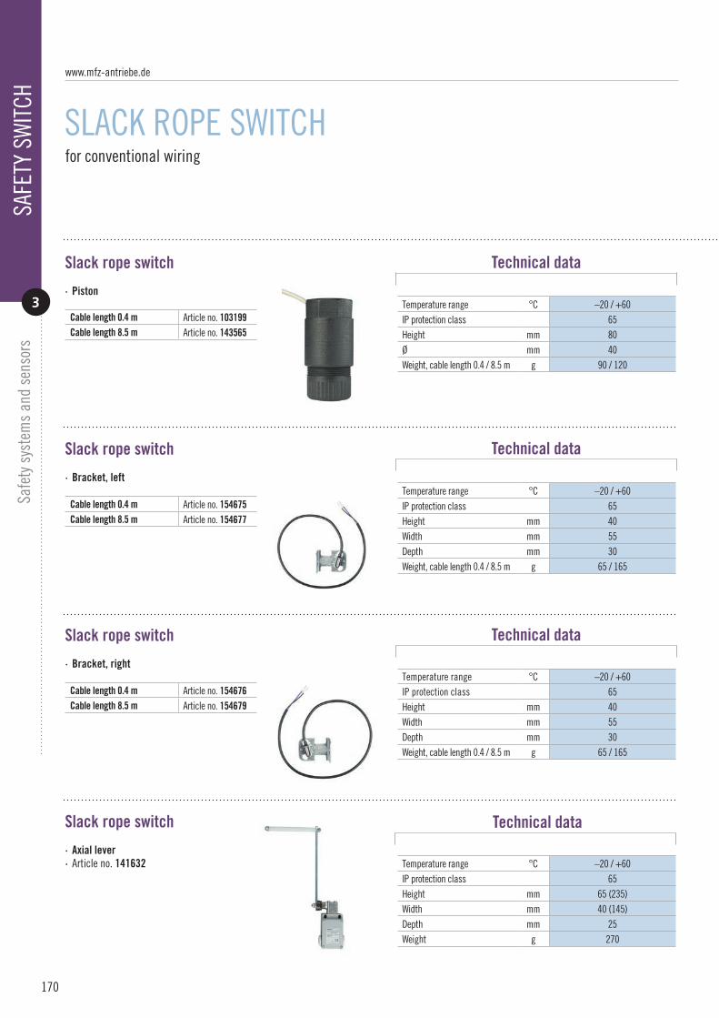
170
for conventional wiring
SLACK ROPE SWITCH
Safe
ty s
yste
ms
and
sens
ors
Slack rope switch
Slack rope switch
Slack rope switch
Slack rope switch
· Piston
· Bracket, left
· Bracket, right
· Axial lever · Article no. 141632
Temperature range °C –20 / +60IP protection class 65Height mm 40Width mm 55Depth mm 30Weight, cable length 0.4 / 8.5 m g 65 / 165
Temperature range °C –20 / +60IP protection class 65Height mm 80Ø mm 40Weight, cable length 0.4 / 8.5 m g 90 / 120
Temperature range °C –20 / +60IP protection class 65Height mm 65 (235)Width mm 40 (145)Depth mm 25Weight g 270
Temperature range °C –20 / +60IP protection class 65Height mm 40Width mm 55Depth mm 30Weight, cable length 0.4 / 8.5 m g 65 / 165
Cable length 0.4 m Article no. 103199Cable length 8.5 m Article no. 143565
Cable length 0.4 m Article no. 154675Cable length 8.5 m Article no. 154677
Cable length 0.4 m Article no. 154676Cable length 8.5 m Article no. 154679
Technical data
Technical data
Technical data
Technical data
www.mfz-antriebe.de
SAFE
TY S
WIT
CH
3

Slack rope switch
Slack rope switch
Slack rope switch
· Piston, pluggable · Article no. 78518
· Bracket left, pluggable · Article no. 154621
· Bracket right, pluggable · Article no. 154620
Pluggable solutions
The pluggable components can be connected directly to the circuit board of the door leaf junction box. The door leaf junction box is mounted onthe door leaf and connected to the door control unit by a spiral cable. Door leaf junction box and spiral cable, see page 166 f.
Temperature range °C –20 / +60IP protection class 65Height mm 80Ø mm 40Weight g 90Cable length m 0,4
Temperature range °C –20 / +60IP protection class 65Height mm 40Width mm 55Depth mm 30Weight g 65Cable length m 0,4
Temperature range °C –20 / +60IP protection class 65Height mm 40Width mm 55Depth mm 30Weight g 65Cable length m 0,4
Technical data
Technical data
Technical data
SAFE
TY S
WIT
CHSa
fety
sys
tem
s an
d se
nsor
s
171
3

172
PHOTOELECTRIC BARRIERS
Safe
ty s
yste
ms
and
sens
ors
One-way photoelectric barrier 24V
Mounting bracket
One-way photoelectric barrier 230V
One-way photoelectric barrier
· Transmitter / receiver· With connection cable· Integrated mounting points for 2 levels · Article no. 80976
· For one-way photoelectric barrier 24V· Especially for mounting on the sectional door rail · Article no. 120448
· Transmitter / receiver· With connection cable · Article no. 96372
· “Two-wire” system· Transmitter / receiver· With connection cable · Article no. 88176
Especially for connection to theMFZ controls CS310 and CS255
Operating voltage V-AC/DC 24Power consumption mA 80IP protection class 65Range m 10Temperature range °C –20 / +60Dimensions (W x H x D) mm 40 x 144 x 60Weight g 930Transmitter connection cable m 12,0Receiver connection cable m 3,0
Important for all photoelectric barriers:Extreme weather conditions (rain, fog, etc.) and an inexact alignment may reduce the range by up to 70%.
Height mm 87Width mm 34Depth mm 228Weight g 700
Operating voltage V-AC/DC 24 – 240Power consumption mA 80IP protection class 65Range m 10Temperature range °C –20 / +60Dimensions (W x H x D) mm 40 x 144 x 60Weight g 930
Operating voltage V-DC 24Power consumption mA 25IP protection class 65Range m 8Temperature range °C –20 / +60Dimensions (W x H x D) mm 23 x 63 x 19Weight g 290Transmitter connection cable m 10,0Receiver connection cable m 10,0
Technical data
Technical data
Technical data
Technical data
www.mfz-antriebe.de
PHOT
OELE
CTRI
C BA
RRIE
RS
4

One-way photoelectric barrier DUO
Draw-in protection photoelectric barrier 24V
OSE light curtain
· Transmitter / receiver· On-line, “leading” system· 2 x OSE transmitter / receiver · Article no. 140539
Touchless monitoring of the safety edge with two light beams.
· Draw-in protection transmitter / receiver · Article no. 96150
Only in combination with a control system from that cyclically tests the transmitter and receiver according to EN 61496-1, category 2, and with a power pack that recognizes changes and interrup-tions of supply voltage according to EN 61496-1.
· Transmitter / receiver· safety light curtain, PL d, cat. 2 · Article no. 162066
The safety light curtain, consisting of a transmitter and receiver, is suitable for all automated door typeswith a minimum door width of 1.6 m.Ensures the necessary safety for vertically and horizontally closing doors according to EN 12978 and EN 12453.
Suitable for installation in the door leaf plane. Special versions on request.
Operating voltage V-DC 12Power input mW 120IP protection class 54Range m 6Temperature range °C –10 / +55Dimensions (W x H x D) mm 52 x 331 x 153Weight g 1900Transmitter connection cable m 1,0Receiver connection cable m 1,0
Operating voltage V-DC 24Power consumption mA 60IP protection class 68Range m 10Temperature range °C –10 / +55Dimensions (W x H x D) mm 73 x 40 x 20Weight g 700Transmitter connection cable m 10,5Receiver connection cable m 10,5
Operating voltage V-DC 24Power consumption mA 50IP protection class 67Range m 10Temperature range °C –20 / +60Dimensions (H x W x D) mm 2555 x 12 x 15Weight g 1860Transmitter connection cable m 15,0Receiver connection cable m 5,0
Protective field height mm 2430Number of beams 20Resolution mm ≥ 50 / 185max. door closing speed m/s 1,3
Technical data
Technical data
Technical data
PHOT
OELE
CTRI
C BA
RRIE
RS
4
Safe
ty s
yste
ms
and
sens
ors
173

174
for the evaluation of ground loops
LOOP DETECTORS
Safe
ty s
yste
ms
and
sens
ors
Detector
Detector in CI housing
Loop cable
Plug-in base
· 1-channel or 2-channel· 2-channel version with direction detection
· 1-channel or 2-channel· Integrated in the housing· Incl. plug-in base
· Article no. 121881
· For detector· For mounting on a cap rail · Article no. 141650
Operating voltage V-AC / V-AC/DC 230 / 24Power consumption mA 12 / 100IP protection class 65Temperature range °C –20 / +60Dimensions (H x W x D) mm 165 x 97 x 145Weight g 690
Temperature range °C –40 / +85Height mm 62Width mm 38Depth mm 26Weight g 55
Operating voltage V-AC / V-AC/DC 230 / 24Power consumption mA 12 / 100IP protection class 54Temperature range °C –20 / +60Dimensions (H x W x D) mm 75 x 38 x 105Weight g 260
Cross-section mm² 1,5Continuous temperature °C 180Short-term temperature °C 230Order quantity m 100
230V, 1-channel230V, 2-channel
Article no. 152554 Article no. 122960
24V, 1-channel24V, 2-channel
Article no. 153719 Article no. 153823
230V, 1-channel230V, 2-channel
Article no. 141693 Article no. 122961
24V, 1-channel24V, 2-channel
Article no. 141719 Article no. 141735
Technical data
Technical data
Technical data
Technical data
www.mfz-antriebe.de
SPEC
IAL
SENS
ORS
5

Radar motion detector
Remote control
· Differentiates between people and vehicles · Direction detection· Suppression of crossing traffic· Field size setting · Article no. 148765
· For radar motion detector · Setting of all parameters from ground level · Batteries included · Article no. 148657
for reliable detection of vehicles and people
Operating voltage V-AC/DC 24Power input W < 2IP protection class 65Temperature range °C –30 / +60Dimensions (H x W x D) mm 102 x 127 x 96Weight g 400max. installation height m 7
MOTION SENSORS
Operating voltage (battery) V-DC 3IP protection class 65Temperature range °C –30 / +60Dimensions (H x W x D) mm 160 x 55 x 22Weight g 85
Technical data
Technical data
SPEC
IAL
SENS
ORS
5
Safe
ty s
yste
ms
and
sens
ors
175

176
for door systems
ACCESS CONTROL SYSTEMS
Safe
ty s
yste
ms
and
sens
ors
Code switching unit
· Article no. 141668
Keyless safety systemfor door systems. Access only possible after entering a 4-digit numeric code. Up to 4 codes are freely programmable.
Operating voltage V-AC 230max. contact load at 250V A 8Evaluation unit IP protection class
54
Keypad IP protection class 65Temperature range °C –20 / +60Dimensions (H x W x D) mm 127 x 139 x 50Weight g 420
Technical data
www.mfz-antriebe.de
ACCE
SS C
ONTR
OL S
YSTE
MS
6

ACCE
SS C
ONTR
OL S
YSTE
MS
6
Safe
ty s
yste
ms
and
sens
ors
177

MFZ Antriebe GmbH & Co. KGNeue Mühle 4D-48739 Legden, Germany
www.mfz-antriebe.de 03/
2018
/EN