serious incident s - gov.uk requires the lateral and vertical navigation modes of the flight...
TRANSCRIPT

10© Crown copyright 2012
AAIB Bulletin: 6/2012 G-JECF EW/C2010/09/04
SERIOUS INCIDENT
Aircraft Type and Registration: DHC-8-402 Dash 8, G-JECF
No & Type of Engines: 2 Pratt & Whitney Canada PW150A turboprop engines
Year of Manufacture: 2004
Date & Time (UTC): 11 September 2010 at 1845 hrs
Location: On approach to Exeter Airport, Devon
Type of Flight: Commercial Air Transport (Passenger) Persons on Board: Crew - 4 Passengers - 49
Injuries: Crew - None Passengers - None
Nature of Damage: None
Commander’s Licence: Airline Transport Pilot’s Licence
Commander’s Age: 44 years
Commander’s Flying Experience: 3,050 hours (of which 1,560 were on type) Last 90 days - 77 hours Last 28 days - 20 hours
Information Source: AAIB Field Investigation
Synopsis
During approach the aircraft experienced a failure of the number 1 Input Output Processor (IOP 1). The flight crew became distracted with this failure and were unaware that the altitude select mode of the flight director had become disengaged and that the aircraft had descended below its cleared altitude. Descent continued until, alerted by an EPGWS warning, the pilots climbed the aircraft and re-established the glidepath. The investigation found that the IOP 1 failure was caused by intermittent electrical contact arising from cracked solder on two pins of a transformer on the IOP power supply module. It was further determined that there was a lack of appropriate operational guidance available to flight crews to deal with such avionics failures. Three Safety Recommendations have been made.
History of the flight
The crew reported for duty at 1135 hrs to fly four sectors,
beginning and ending at Exeter Airport. The first three
sectors passed without incident and the aircraft took off
at 1727 hrs for the last sector, from Bergerac. There
were no apparent defects and the commander was the
handling pilot.
After an uneventful flight the crew began their approach
to Exeter Airport. They were cleared by ATC to
descend to an altitude of 2,600 ft, the sector MSA, and
given radar vectors to position the aircraft for an ILS
approach to Runway 26. The crew reported that the
aircraft was being flown with the autopilot engaged,
the approach mode of the flight director armed and
descending in the vertical speed mode. When passing

11© Crown copyright 2012
AAIB Bulletin: 6/2012 G-JECF EW/C2010/09/04
an altitude of approximately 3,300 ft the flight crew noticed that the IOP1 FAIL annunciator on the engine display (ED) was illuminated. They also noticed that the commander’s speed bugs and minimum descent altitude setting on his primary flight display (PFD) had been replaced with white dashes, whilst the co-pilot’s PFD indications remained normal. The commander attempted to regain indications on his PFD by switching the air data computer (ADC) source selector from the NORM position to ADC 2. When this had no apparent effect he reselected NORM. The commander realised that by changing ADC selection the approach mode had become disarmed and so, on re-selecting NORM, he also re-armed the approach mode. Having no speed bug information on his side, the commander then decided to hand control to the co-pilot for the landing. The horizontal situation indicator selector (HSI SEL), which is normally selected to the handling pilot’s side, remained selected to the commander’s side. The pilots considered this would not affect the operation of the aircraft at that stage of the flight. The crew commented, after the event, that when the HSI selection is changed it requires the lateral and vertical navigation modes of the flight director (FD) to be re-selected.
Shortly after the co-pilot took control, a GPWS ‘CAUTION TERRAIN’ alert sounded. Both pilots had been trying to resolve the IOP 1 failure and on hearing the caution looked up. They stated that they were in VMC and could see clearly the runway ahead. Within a few seconds of the initial caution a GPWS ‘TERRAIN
TERRAIN, PULL UP’ warning sounded. The co-pilot stated that he disengaged the autopilot and advanced the power levers to about 80% power and began climbing the aircraft at a pitch angle of approximately five degrees. He commented that he was confident that this pitch angle would be adequate to provide terrain clearance under the circumstances.
The co-pilot’s reaction to the GPWS warning coincided with ATC asking the crew to confirm they were descending with the glideslope. The commander had by then realised that the ALT SEL function of the FD had become deselected, allowing the aircraft to descend below the selected altitude. He informed ATC that the aircraft had had an instrument failure and that it was climbing to capture the glideslope. The aircraft climbed to 2,200 ft and captured the glideslope before landing without further incident at 1851hrs.
Weather
The crew reported that the weather had been “good” at the time of the incident and VMC prevailed throughout the approach. Official night was at 1909 hrs, about 25 minutes after the GPWS warning, and the crew described the light conditions at the time as dusk, with the ground clearly visible.
Exeter ATIS, timed at 1820 hrs, reported the following conditions:
Wind: 290º/10 ktVisibility: in excess of 10 kmCloud: FEW at 2,500 ftTemperature/dew point: 17/13ºCQNH: 1016 Mb
Flight recorders
The aircra ft’s flight data recorder (FDR) contained information from the incident flight. Recordings of the flight on the cockpit voice recorder (CVR) had been overwritten with more recent recordings because it had not been isolated.
Figure 1 shows the salient parameters recorded on the FDR during the incident flight. The figure starts at 1849 hrs with the aircraft descending and the autopilot

12© Crown copyright 2012
AAIB Bulletin: 6/2012 G-JECF EW/C2010/09/04
engaged with heading, altitude seleCt and vertiCal speed modes of the Fd selected. the selected altitude was 2,600 ft and the selected vertical speed was -500 ft/min.
at 1849:31 hrs the Fdr recorded an adC reversion in which all the selected Fd modes disengaged and the Fd reverted to pitCh hold and roll hold1; the selected vertical speed also reset to zero. Five seconds later heading mode was reselected.
approximately 15 seconds later the power levers were retarded, causing the airspeed to start reduce while the aircraft continued to descend. as the aircraft passed through 2,600 ft the heading mode was deselected for 2 seconds and, as the bank angle was now less than 6º, the autopilot reverted to wings level mode. the heading mode was then reselected again followed by flap 5.
after a further 25 seconds, at 1850:37 hrs, during which the aircraft had descended to 2,185 ft amsl (1,680 ft agl) and slowed to 162 kt CAS, the flight director mode changed from heading to loCaliser. it remained in loCaliser mode for 37 seconds, during which the aircraft continued to descend and slow down. during this descent, at 1851:00 hrs, a gpws “Caution terrain” aural alert sounded for 1 second. the aircraft was passing 1,759 ft amsl (1,066 ft agl), and indicating a deviation of approximately ¾ of a dot below the glideslope. at 1851:09 hrs the hsi sel button was selected to the right side, resulting in the localiser mode being cancelled. the aircraft then reverted to wings level mode for 2 seconds until the hdg mode was selected. the aircraft maintained a continuous
Footnote
1 Flight director mode reversion is described in the section ‘Flight director control’.
deceleration during the decent, with the power lever position remaining unchanged for approximately 55 seconds until the gpws ‘pull up’ warning sounded. the minimum airspeed recorded was 146 kt Cas2. shortly afterwards the power was increased and the aircraft started to accelerate but continued to descend.
at 1851:14 hrs the gpws “terrain terrain,
pull up” aural warning sounded and continued for 12 seconds. the aircraft started to climb within 9 seconds of the initiation of this warning. The flaps remained extended at flap 5 throughout the climb and the minimum altitude recorded was 1,417 ft amsl (700 ft agl), when the aircraft was approximately 8 nm from touchdown.
Aircraft information
the aircraft experienced an iop failure during the approach. there are two iops installed on the aircraft, and these are part of the Flight data processing system (Fdps), which is responsible for acquiring data from various aircraft systems and sensors and routing this data to other aircraft systems. these include the electronic Instrument System (EIS) (which displays primary flight data, navigation, engine and system parameters on five liquid crystal display units (du) in the cockpit), the Flight data recorder (Fdr), the autopilot (a/p), the Stall Warning and the Traffic Collision Avoidance system (tCas). a failure of one or both iops can result in a loss of some cockpit indications.
Footnote
2 the ‘Normal procedures – approach and landing’ section of the Operations Manual stated that the normal speed for flap 5 at that stage of the approach was 170 kt. it also stated that the minimum manoeuvring speed should be vref Flap 5 +10 kt, which at the estimated aircraft weight was 143 kt.

13© Crown copyright 2012
AAIB Bulletin: 6/2012 G-JECF EW/C2010/09/04
Figure 1
Salient FDR parameters

14© Crown copyright 2012
AAIB Bulletin: 6/2012 G-JECF EW/C2010/09/04
IOP failure modes
When an IOP is confirmed failed the caption IOP 1 FAIL
or IOP 2 FAIL is displayed as an advisory message on the Engine and System Integrated Display (ED) (IOP
S FAIL is displayed if both are failed). This caption is generated if there is a loss of transmission between the IOP and the active ED greater than 10 seconds duration, due to a wiring malfunction or automatic shutdown of the IOP upon an internal error. It also displays if the IOP status is set to FAIL by the opposite IOP due to failure of the IOP input / output interface. The AVIONICS CAUTION light will also illuminate on the overhead warning and caution panel, but only when the aircraft is on the ground and aircraft speed is less than 50 kt. There are no flight crew procedures for ED advisory messages relating to avionics failures such as an IOP failure, but maintenance action is required prior to dispatch of the next flight.
In the event of an IOP failure, several cockpit indications are lost. All the parameters which are only acquired by one, rather than both, of the IOPs, will be lost if the respective IOP fails. For an IOP 1 failure these include: left fuel inlet temperature (displayed on the ED); left main oil pressure (displayed on the ED); and hydraulic quantity for systems No 1 and No 3 (displayed on the MFD). For an IOP 2 failure they are: right fuel inlet temperature (displayed on the ED); right main oil pressure (displayed on the ED); and hydraulic quantity for system No 2 (displayed on the MFD). In addition to these, other cockpit indications may also be lost, depending on the precise nature of the fault that has caused the IOP to register a fail status. The associated cockpit effects may include, but are not limited to: the loss of speed bugs (displayed on the PFD airspeed indicator); loss of Decision Height (DH) and Minimum Descent Altitude (MDA) (displayed on the
PFD) indications; inadvertent aural warnings; a CAT 2
FAIL advisory message; and the loss of the “MINIMUMS-
MINIMUMS” callout during approach.
The FDPS system performs Power On Start-up Tests (POSTs) and performs a continuous test routine during operation. Any failures which effect the functioning of the FDPS are stored in the Built-in Test Equipment (BITE) memory and transmitted to the Central Diagnostic System (CDS).
Defect history
The IOP unit installed in position 1 at the time of the incident was Serial Number (S/N) 364. A review of the aircraft technical log and the operator’s recurrent defects database shows that the recent defect history commenced on 22 August 2010 when an entry was made indicating that an IOP 1 FAIL had occurred. Maintenance troubleshooting was carried out in accordance with the manufacturer’s Fault Isolation Manual (FIM) and an operational test of the IOP was performed in accordance with the Aircraft Maintenance Manual (AMM). No fault codes were generated and the aircraft was returned to service.
The next entry reporting an IOP 1 FAIL refers to the incident flight on 11 September 2010. The relevant circuit breaker was reset and an operational test of the IOP generated normal indications. The aircraft was released to service with a request for further reports from flight crew.
Two further reports of IOP 1 FAIL were made on 20 September 2010. After the first occurrence, no faults were noted in the CDS and an operational test of the IOP revealed no faults. In response to the second occurrence the IOP 1 unit (S/N 364) was swapped into the IOP 2 position for further reports. The operational

15© Crown copyright 2012
AAIB Bulletin: 6/2012 G-JECF EW/C2010/09/04
test was carried out again with no findings, and the aircraft was released to service with S/N 364 in IOP 2 position.
An occurrence of IOP 2 FAIL was reported on 23 September 2010. This was not noted in the technical log because a removal and re-application of electrical power to the system, performed on the ground by the flight crew, caused the indication to disappear.
A further report of an IOP 2 FAIL was noted on 1 October 2010, after which the operational test was carried out satisfactorily and the unit was re-installed.
On 7 October 2010 an IOP 2 FAIL was reported. The IOP units were again swapped into the opposite positions for fault-finding during the troubleshooting. All tests were performed satisfactorily, and the units were swapped back again prior to release of the aircraft to service, with S/N 364 in the IOP 2 position.
On the 8 October 2010 another occurrence of IOP 2 FAIL
was reported. Subsequent troubleshooting confirmed a fault and S/N 364 was removed from the IOP 2 position and replaced. The removed unit was then sent to the vendor’s overhaul facility for testing and repair.
IOP reliability
The operator reported that ‘IOP fail’ indications are common events on their Dash 8 Q400 fleet. While they are considered to be a cause of operational delays, due to the requirement for maintenance intervention prior to dispatch of the next flight, IOP removals do not feature among the most frequent component removals on the fleet. Only approximately 20% of ‘IOP fail’ reports result in a confirmed failure and subsequent removal of the unit from the aircraft. In the majority of cases, the operator’s experience is that resetting the
relevant circuit breaker or re-installing the unit appears to solve the problem, and the unit remains in service. Many reports refer to isolated events. Where multiple reports for the same unit are received, these units may operate normally for several weeks or months between indicated failures.
The operator has noted that a number of IOP units removed and sent to the vendor for repair after the faults were confirmed during maintenance troubleshooting, have been returned with the statement ‘No Fault Found (NFF)’ but subsequently continued to cause problems when reinstalled on an aircraft. As a result, the operator had adopted a process of tracking the serial numbers of suspect units. After the third occasion on which a particular unit is faulted on an aircraft but no faults are detected during workshop testing, it is designated as a ‘rogue’ unit and not permitted back into the operator’s spares inventory. At the time of the incident, the operator had identified three rogue units in this way. From a review of the operator’s records there was no indication that the incident unit, S/N 364, had been removed for vendor testing or repair prior to its removal on 8 October 2010.
The IOP manufacturer is aware of the issues reported by the operator and in 2010 established an NFF Task Force for ‘repeater’ units which repeatedly test NFF in the workshop but continue to cause problems when returned to service. The manufacturer has developed an action plan to detect faults which cannot be reproduced during Acceptance Test Procedures (ATP) in the workshop. These actions consist mainly of visual inspection of the electronic boards for signs of corrosion, dust, impact, missing varnish or solder and visual inspection and vibration testing of sensitive components such as connectors. Through this process, a number of weak components have been identified

16© Crown copyright 2012
AAIB Bulletin: 6/2012 G-JECF EW/C2010/09/04
which can be considered common contributors to IOP failures. One such component is the secondary power supply module on the IOP CPU board, known as the ERACLE module.
Of 34 unscheduled IOP removals from the operator’s Dash 8 fleet between March 2007 and August 2010, 10 units satisfactorily passed the ATP and were returned to the operator as NFF. Seven units (including three which had previously tested NFF) required replacement of components on the ERACLE secondary power supply module. In the 12-month period to the end of October 2010, there were 17 unscheduled IOP removals, including S/N 364.
Operator tracking of recurrent defects
The operator monitors repetitive defects for their entire fleet via a spreadsheet which is manually updated daily based on defects reported in the previous day’s technical log sheets. It also uses an electronic technical log system, which generates an automated alert if a particular defect has occurred 3 times within a rolling 21-day period. This system generally operates with a time lag of a few days, due to delays associated with data entry, limiting the efficacy of the alerting function. Also, nuisance alerts are common. The operator therefore considers that the repetitive defect spreadsheet is the primary tool for monitoring and reporting repetitive defects within the organisation. Quarterly ‘Reliability’ meetings held by the company are attended by representatives of the Civil Aviation Authority (CAA), as part of their operator oversight function. The CAA consider that the processes in place for the monitoring of recurrent defects are adequate.
IOP Testing
The removed IOP was sent to the manufacturer’s repair facility where extensive testing was performed in
consultation with the AAIB and under the supervision of the French ‘Bureau d’Enquêtes et d’Analyses pour la sécurité de l’aviation civile’ (BEA).
Analysis of the IOP Non Volatile Memory (NVM) memory content showed that the CDS recorded two internal IOP failures at 18:46 hrs on 11 September 2010, corresponding to the time of the incident, and again on 20 September 2010, corresponding to the subsequent IOP failures reported in the technical log. The unit was tested in accordance with the manufacturers ATP to determine the cause of these failures. This is a test programme used in production and maintenance to identify hardware failures and requires a series of functional tests to be performed on the unit on a test bench. The unit initially tested ‘No Fault Found.’ As it was not possible to reproduce the IOP failure on the test bench it was considered that an intermittent fault may exist so a further more robust and iterative test schedule was devised and performed on a dedicated systems test rig, to simulate the aircraft environment and flight conditions during the incident. The IOP was subject to long operating periods and varying temperatures on the test rig; an ATP test was also performed before and after each temperature endurance test. Following many iterations of these tests, an intermittent fault was identified. The unit subsequently failed Part 2 of the ATP which specifically tests the IOP power supply, and this pointed to a problem with the ERACLE secondary power supply module. The fault was also successfully repeated at ambient temperature. During further testing the fault became permanent, rather than intermittent and was traced to the -15 V DC output of the ERACLE module.
An X-ray examination of the ERACLE secondary power supply module revealed cracks in the solder of some of the surface-mounted components on one

17© Crown copyright 2012
AAIB Bulletin: 6/2012 G-JECF EW/C2010/09/04
of the electronic boards, in particular the pins of the TR1 transformer. It was concluded that the cracked solder would have caused intermittent electrical contact in the -15 V DC power supply path and led to the intermittent fault on IOP S/N 364 experienced during the incident flight and repeated during subsequent testing.
Flight director control
The flight director (FD) and autopilot (AP) are functions of the AFCS. The FD function provides lateral and vertical guidance to fly the aircraft, displayed in the form of a vertical and horizontal bar on each pilot’s PFD. The pilot can manually fly the displayed commands or engage the AP which couples the FD guidance to the aircraft control surfaces for automatic control of the aircraft. Pilots manage the flight director and autopilot engagement using a flight guidance control panel (FGCP) mounted in the centre of the glare shield above the main instrument panel, and via two buttons on each pilot’s control wheel.
The status of the FD is displayed on the flight mode annunciator (FMA) at the top of each PFD. The FMA has three fields. Vertical guidance modes are indicated in the right hand field and lateral modes in the left hand field. The modes appear in white if armed and in green if active. A mode is considered to be engaged only when it is indicated on the FMA, not just when the associated pushbutton has been pressed. It is vital that pilots monitor the FMA in response to each selection on the FGCP or control wheel.
Altitude Select mode
In the ALTITUDE SELECT mode the FD provides commands to acquire and hold a selected altitude target. It has ARM and CAPTURE sub-modes. To operate the ALTITUDE SELECT mode, pilots must pre-select
an altitude target using the ALT knob, press the ALT
SEL pushbutton to arm the mode and manoeuvre the aircraft towards the pre-selected altitude target using a FD vertical mode.
When armed, the symbol ‘ALT SEL’ appears in white on the FMA. If the ALTITUDE SELECT mode is not armed, the aircraft will continue through the selected altitude in the active vertical mode unless either pilot intervenes to change the flight path.
Vertical modes
The aircraft can be manoeuvred vertically in several modes using the FD and AP. The pilots of G-JECF used the VERTICAL SPEED mode to descend the aircraft towards the selected altitude of 2,600 ft. This mode is activated by pressing the VS pushbutton on the FGCP and indicated by the symbol ‘VS’ in green in the right hand field of the FMA, when active. The desired vertical speed is selected using the pitch thumbwheel in the centre of the FGCP, and is indicated beside the ‘VS’ symbol in the same FMA field.
With the AP engaged, and in the absence of further pilot inputs or system failures, as the aircraft approaches the selected altitude, the FD will change automatically to the altitude capture mode and the symbol ‘ALT*’ (referred to by this operator as ‘altitude live’) will appear in green on the FMA. As the aircraft levels at the selected altitude, the FD will change automatically to the ALTITUDE HOLD mode and the symbol ‘ALT’ will appear in green on the FMA.
If, before the FD enters a capture mode, the altitude selection is changed to one above the current aircraft altitude, or if the altitude select mode is disengaged, the aircraft will continue to descend in the active vertical mode until the pilots intervene to change the flight path.

18© Crown copyright 2012
AAIB Bulletin: 6/2012 G-JECF EW/C2010/09/04
Vertical basic (pitch hold) mode
The PITCH HOLD mode is the default basic vertical guidance mode and is activated in the case of an ADC reversion; when any other active vertical mode is de-selected by the pilot; if the AP is engaged and no other vertical mode is active; or when a lateral mode is active and no other vertical mode is active. In this mode the FD provides commands to hold a target pitch attitude; the pitch target is initially set to the aircraft pitch attitude that exists when PITCH HOLD is activated.
Lateral modes
The aircraft can be manoeuvred laterally in several modes using the FD and AP. The pilots of G-JECF used the HEADING SELECT mode to acquire and hold a selected heading target, as they positioned the aircraft to acquire the ILS localiser and glideslope signal. This mode is activated by pressing the HDG SEL pushbutton on the FGCP and indicated by the symbol ‘HDG SEL’ in green in the left hand field of the FMA, when active. The desired heading is selected using either the left or right HDG knobs on the FGCP, depending upon which PFD is coupled to the FD.
Lateral basic modes
The default lateral basic mode is activated if the AP or a vertical FD mode is engaged when no other lateral mode is active. There are three sub-modes, which automatically transition when the appropriate flight conditions are met. In the ROLL HOLD sub-mode the FD commands to hold a target roll attitude, equivalent to the bank angle at the time of mode engagement, and is selected if the roll angle is greater than 6°. In WINGS
LEVEL sub-mode the FD commands to hold a zero degree bank angle, and is selected if roll angle is less than greater than 6°. In the HDG HOLD sub-mode the FD commands to hold a target heading, equivalent to the
heading at the time of mode engagement, and is selected if the roll angle is less than 3° for 10 seconds.
ILS Approach mode
The ILS APPROACH mode is a combined lateral and vertical mode in which the FD captures and tracks the ILS localiser (lateral) and glideslope (vertical) beams. When an appropriate ILS frequency is tuned and selected as the navigation source, the GLIDESLOPE sub-mode (and, simultaneously, the LOCALISER sub-mode) is armed by pressing the APPR pushbutton on the FGCP and indicated by the symbol ‘gS’ in white on the FMA.
As the aircraft approaches the ILS glidepath, the FD will change automatically to the GLIDESLOPE CAPTURE
mode and the symbol ‘GS*’ (referred to by this operator as ‘glideslope star’) will appear in green on the FMA. Having intercepted the glideslope beam, the FD will change automatically to the GLIDESLOPE TRACK mode and the symbol ‘GS’ will appear in green on the FMA. If the vertical path of the aircraft remains below the ILS glideslope, the FD will not be able to capture the glideslope and the aircraft will continue to descend in the active vertical mode unless the pilots intervene to change the flight path.
For an ILS approach, the position of the aircraft relative to the localiser and glideslope beams is also presented on separate localiser and glideslope deviation scales on the PFD. Deviation from the glideslope and localiser course is expressed in terms of ‘dots’ (eg the aircraft may be described as being 1 dot left or right of localiser or 1 dot above or below glideslope). This display is commonly referred to as ‘raw data.’
Flight director source selection
The HSI SEL pushbutton on the FGCP selects which PFD (1 or 2) is coupled to. Pressing the HSI SEL

19© Crown copyright 2012
AAIB Bulletin: 6/2012 G-JECF EW/C2010/09/04
pushbutton switches from the left side system inputs displayed on the pilot’s PFD, to the right side system inputs displayed on the co-pilot’s PFD and vice versa. The HSI SEL is selected to the side of the handling pilot before the flight. The selected side is indicated by illuminating the corresponding arrow next to the HSI
SEL button. The selected side is also indicated on the non-selected PFD by an HSI caption plus and arrow. If the dual FD mode is active, both the left and right side arrows adjacent to the HSI SEL pushbutton are illuminated and pressing HSI SEL has no effect. Pressing the HSI SEL pushbutton has the following effect on the AFCS: no effect on AP / yaw damper engagement; clears all the active and armed lateral and vertical FD modes, and removes the FD bars if the AP is not engaged; clears all the active and armed lateral and vertical FD modes if the AP is selected. The FD modes revert to basic modes and the FD bars remain.
Enhanced ground proximity warning system (EGPWS)
The EGPWS monitors the flight path of the aircraft and compares aircraft position, attitude, airspeed and glideslope inputs with internal terrain, obstacle and airport databases to determine if the present flight path would result in impact with terrain and, if so, will provide visual and aural indications to alert the pilots. The EGPWS provides the indications well ahead of the projected collision with terrain. In the event that a caution or warning alert is triggered, an automatic display of the terrain feature on the MFDs is activated.
When the conditions have been met to generate a Terrain Caution Alert, the “CAUTION TERRAIN, CAUTION
TERRAIN” audio alert is triggered, the TERRAIN CAUTION
light is illuminated and the background image on the terrain display on the MFD is enhanced to highlight the terrain caution threats. The audio alert is repeated after
seven seconds if the aircraft is still within the terrain
caution envelope.
When the conditions have been met to generate a
Terrain Warning Alert , the “TERRAIN TERRAIN, PULL
UP” audio alert is triggered, the TERRAIN WARNING
light is illuminated and the background image on the
terrain display is enhanced to highlight the terrain
warning threats. The phrase “PULL UP” is then
repeated continuously while within the terrain warning
envelope.
Standard operating procedures (SOPs)
Part B4 of the operator’s operating manual makes
several references to the importance of monitoring
the flight path of the aircraft. Section 2.4 includes the
statement:
‘PF’s3 main task is to fly the aircraft and monitor
its flight path. PNF4 must also monitor the
aircraft flight path wherever possible whilst
carrying out his other tasks.’
Abnormal and Emergency Procedures
Division of responsibility
Chapter 2 of Section 3 of the Dash 8 Q400 Operating
Manual prescribes the division of responsibility
between the two pilots when dealing with abnormal
and emergency procedures. It states that the pilot
flying remains responsible for the safe navigation of
the aircraft ‘in three dimensions’. It also identifies that
the pilots may need to change role, should the failure
result in the loss of instruments on the side of the pilot
flying.
Footnote
3 Pilot flying.4 Pilot not flying.

20© Crown copyright 2012
AAIB Bulletin: 6/2012 G-JECF EW/C2010/09/04
IOP failures
The operator publishes its own version of the manufacturer’s QRH which it refers to as the Emergency Checklist (ECL). The ECL largely resembles the QRH but is not necessarily identical. Section 25B of the ECL refers to Engine Display advisories (Figure 2). Issue AL-17 of this page, dated April 2010 was valid at the time of the incident and contained no information on either single or dual IOP or IOM failures, other than to advise that the avionics caution light would illuminate when the aircraft was on the ground. The equivalent manufacturer’s QRH also contained no information on these failures at that time.
The operator considered information regarding avionics failures annunciated on the engine display (ED) screen was not suitably comprehensive and raised the matter with the aircraft manufacturer, prior to this incident, in July 2009 at a meeting of the manufacturer’s Flight Operations Steering Committee.
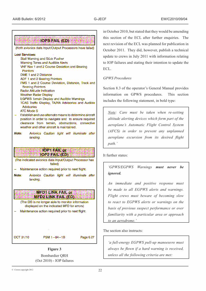
The manufacturer subsequently amended Chapter 6 of the QRH to include enhanced information about dual IOM and IOP failures, but did not include information regarding single IOP failures. This revision of the QRH was published in October 2010, and the relevant extract is shown in Figure 3.
Following the incident, the operator reported that early in 2011 they had, on the ground, replicated the effects of failing each IOP in turn and also both together by pulling the relevant IOP circuit breakers. They stated that the resulting individual IOP failures produced a significant loss of information on the on-side PFD. They stated that, significantly, an IOP 1 failure caused the disappearance of ALTITUDE SELECT mode together
with all other lateral and vertical FD modes and the left side landing speed bugs. They reported that failure of IOP 2 did not cause a loss of ALTITUDE SELECT mode, but did result in the loss of the active and armed lateral and vertical FD modes. Additionally they reported that failure of both IOPs caused an even more significant loss of cockpit indications, this being greater than the sum of the individual IOP failures observed.
The IOP manufacturer subsequently reported to the investigation that the circuit breaker pulled by the operator is common to IOP 1, IOM 1 and Flight Guidance Module 1 (FGM 1) and advised that it was not possible to replicate the individual effects of an IOP 1 failure by this means. The IOP manufacturer further stated that this explained the loss of ALTITUDE SELECT mode observed by the operator during ground testing.
Believing that the extent of the observed loss of indications, both in the case of individual and dual IOP failure, was not fully reflected in the manufacturer’s amended QRH caused the operator to register a technical query (CNAG-Q11-8126308) with the manufacturer on 22 March 2011.
This requested a review of the drills for failure of either IOP 1 or IOP 2 and for both IOP 1 and 2 and highlighted the fact that the loss of ALTITUDE SELECT
mode with a failure of IOP 1 or both IOPs together was not mentioned in the relevant drills. In their response, dated 5 April 2011, the manufacturer stated that they were:
‘investigating all mode failures relating to IOM/IOP and will amend the QRH accordingly.’
The operator did not include in their ECL the changes relating to IOP failures published by the manufacturer

21© Crown copyright 2012
AAIB Bulletin: 6/2012 G-JECF EW/C2010/09/04
Figure 2
FlyBe ECL Section 25B (rev A/L 17) Engine Display advisories
22© Crown copyright 2012
AAIB Bulletin: 6/2012 G-JECF EW/C2010/09/04
Figure 3
Bombardier QRH(Oct 2010) - IOP failures
in October 2010, but stated that they would be amending this section of the ECL after further enquiries. The next revision of the ECL was planned for publication in October 2011. They did, however, publish a technical update to crews in July 2011 with information relating to IOP failures and stating their intention to update the ECL.
GPWS Procedures
Section 8.3 of the operator’s General Manual provides information on GPWS procedures. This section includes the following statement, in bold type:
Note: Care must be taken when re-setting altitude alerting devices which form part of the aeroplane’s Automatic Flight Control System (AFCS) in order to prevent any unplanned aeroplane excursion from its desired flight path.’
It further states:
‘GPWS/EGPWS Warnings must never be ignored.
An immediate and positive response must be made to all EGPWS alerts and warnings. Flight crews must beware of becoming slow to react to EGPWS alerts or warnings on the basis of previous suspect performance or over familiarity with a particular area or approach to an aerodrome.’
The section also instructs:
‘a full-energy EGPWS pull-up manoeuvre must always be flown if a hard warning is received, unless all the following criteria are met:
Jack Walker House, Exeter International Airport, Exeter, Devon, EX5 2HL, UK
Tel: +44 (0)1392 366 669 Administration
+44 (0)8717 000 123 Reservations
Fax: +44 (0)1392 366 151
Telex: 42763 JEA EXTG Sita: EXTAPJY
I have had the opportunity to see in the aircraft (on the ground) the effect of failing individual IOP’s and both together. Individual IOP failures produce a significant number of information dropouts on the on-side primary flight displays (PFD). Significantly, loss IOP 1 causes the disappearance of ALT SEL along with all roll and pitch flight director modes and the left side landing speed bugs. The crew would still receive the audio and visual altitude alerts (as the selected altitude remains) but the aircraft would not capture any selected altitude. Failure of IOP 2 does not cause loss of ALT SEL, but does lose the PFD flight director modes. Failing both IOP’s causes very significant loss of information presented to the Flight Crew that is greater than the sum of individual IOP failures.

23© Crown copyright 2012
AAIB Bulletin: 6/2012 G-JECF EW/C2010/09/04
● Below 1,000ft AAL
● Clear visual conditions
● Runway in sight
● Established on the final approach track
● Established on the correct vertical profile as confirmed by an electronic glideslope or visual indicator (eg VASI/PAPI)
● Stabilised in the landing configuration with approach power set
● It is immediately obvious to the flight crew that the aircraft is in no danger in respect of its configuration, proximity to terrain or its current flight path.’
In addition, section 27A of the ECL refers to GPWS events5, and is shown in Figure 4.
Operator’s accident and incident handling procedures
Part A, Section 12 of the operator’s Operations Manual relates to the handling of accidents and incidents.
Section 11.2 gives guidance on the actions to be taken by a commander and the logistics department in the event of an accident. Section 11.3 gives guidance on air safety and mandatory occurrence reporting. Section 11.1.11 defines a serious incident and gives various examples, including ‘Controlled flight into terrain (CFIT) only marginally avoided’; however, neither section 11.2 or 11.3 refers directly to how serious incidents should be handled.
Footnote
5 The GPWS go around attitude (GA Attitude) referred to in the checklist for this aircraft type, under the prevailing configuration, would have been nine degrees.
Section 11.3 requires the commander to send any incident report to the Flight Safety Department via the operator’s internal electronic system. These reports are then distributed for investigation by Central Safety, a position manned by an administrator within the Flight Operations Department during normal office hours. The Operations Manual instructs that outside office hours the Logistics Duty Manager should communicate any issue of an ‘urgent Flight Safety nature’ to the Flight Operations General Manager. The manual does not make clear how, in these circumstances, the Logistics Duty Manager would become aware of any such event.
Section 11.2.1 ‘Action by Commander and Logistics Department’ includes a list of subsequent actions to be taken. This includes the instruction that:
‘Following an accident or incident in which it is necessary to contact the Chief Inspector of Accidents, the crew are immediately grounded. No allocation of blame is attached to this automatic procedure which can only be lifted by the Chief Pilot, or in his absence the Fleet General Manager.’
Section 11.4 refers to the preservation, production and use of FDR and CVR recordings. The version in place at the time of the incident is reproduced below.
On 1 September 2010 the operator published Notice to Air Crew (NOTAC) 84/10, containing revised policy information on the preservation of CVR and FDR data. This was in response to information published by the CAA to all commercial operators as a result of AAIB Safety Recommendation 2010-012.

24© Crown copyright 2012
AAIB Bulletin: 6/2012 G-JECF EW/C2010/09/04
Figure 4
FlyBe ECL - GPWS Extracts

25© Crown copyright 2012
AAIB Bulletin: 6/2012 G-JECF EW/C2010/09/04
NOTAC 84/10
BACKGROUND
This NOTAC has been published in response to AAIB safety recommendation 2010-012. The recommendation concerns an incident where the investigation was hampered by unintentional overwriting of the cockpit voice recording, which erased information necessary to assist the investigation. The Cockpit Voice Recorder (CVR) is designed to record audio information when the electrical power is selected on the aircraft, and is designed to preserve either 30 minutes or 2 hours of audio information (depending on type). In the particular reported incident, because the system was not isolated to preserve the recording, the CVR continued to function during the subsequent maintenance activities following the event and therefore all the audio information relating to the event was lost. Evidence from other previous incidents identified that even where the Flight Crew had isolated electrical power to the CVR, subsequent maintenance or other activity may have reinstated the power supply resulting in the unintentional loss of the recording.
POLICY
Preservation of flight recorder information (CVR & FDR) is covered by the following
a) The Captain or in his absence the First Officer shall ensure, to the extent possible, in the event an aeroplane becomes involved in an accident or incident, the preservation of all related flight recorder records and, if necessary, the associated flight recorders, and their retention in safe custody pending their disposition.
b) In the absence of the Flight crew, the attending engineer needs to ensure that the above is followed.
c) Following an accident, the Pilots of an aeroplane on which a flight recorder is carried shall, to the extent possible, preserve the original recorded data pertaining to the accident, as retained by the recorder for a period of 60 days unless otherwise directed by the investigating authority. This is either the AAIB (Air Accidents Investigation Branch) or Flight Safety. When appropriate, the relevant circuit breakers should be pulled and collared/tagged and an entry made in the aircraft technical log to make clear to any airline personnel that an investigation is in progress. Furthermore, confirmation from the investigating authority/operator is required to be obtained before systems are reactivated and power restored. At stations where contract maintenance or ground handling is carried out by a third party, relevant departments should ensure that the contracted organisation is made aware of all the relevant procedures.
Chief Pilot
Reporting of the incident
After landing, the commander submitted an air safety
report (ASR) via the operator’s internal electronic
network. The ASR was titled ‘IOP 1 Failure Leading to Descent below Platform Altitude for the ILS and subsequent GPWS warnings’. The FDR and CVR
were not isolated, either by the pilots or engineering
staff.

26© Crown copyright 2012
AAIB Bulletin: 6/2012 G-JECF EW/C2010/09/04
Two days later, on Monday 13 September 2010, Central Safety processed the ASR and allocated it to the Engineering Safety Department for action. It was also distributed to various other departments and managers for information, including the Chief Pilot, Flight Safety Department and relevant fleet managers. The Flight Safety Department had also been contacted on the same day by the commander who wished to discuss the event. It was as a result of this discussion that a decision was made not to remove the crew from flying duty. A copy of the flight data was also requested to be downloaded from the aircraft.
On Wednesday 15 September 2010 the Engineering Safety Department handed the matter over to the Flight Safety Department who, that afternoon, contacted the AAIB to report it as a serious incident.
On Friday 17 September 2010, having reviewed the flight data, it became apparent to the operator that the crew had not responded properly to the GPWS ‘TERRAIN
TERRAIN, PULL UP’ warning. It was decided, as a result, to ground both pilots until they had undergone remedial training.
Flight Safety Department
At the time of the occurrence the operator’s Flight Safety Department was led by a Flight Safety Manager supported by a Flight Safety Officer and a Flight Safety Co-ordinator. There was also a part-time administrative assistant. The department carried out safety functions, including the operator’s flight data monitoring programme, covering 14 bases and 70 aircraft and over the 12 months preceding the incident had dealt with about 3,100 ASRs.
Previous occurrences
AAIB report EW/C2008/12/05 concerns two previous events involving the same operator and aircraft type in which aircraft descended below their cleared level during approach due to inappropriate mode selection of the flight director, and inadequate monitoring of the FMA annunciations.
Analysis
Effect of IOP I failure
The commander reported the loss of speed bugs and MDA indications on PFD 1 coincident with the IOP 1
fail advisory message on the ED. The System Safety Analysis for the EIS, and the FMECA contained therein describe a number of IOP failure scenarios which can result in the loss of these and other cockpit indications. Although the observed loss of indications was in keeping with the expected system response and can therefore be considered in accordance with the system design, this represented a significant distraction to the crew at a late stage in the approach.
The ‘IOP FAIL’ message on the ED is an advisory message and there is no requirement in the manufacturer’s QRH checklist for any flight crew action to be taken in response to this indication. In an attempt to regain the lost indications on his PFD, however, the commander decided to switch the ADC source selector to ADC2, and then back again when this did not have the desired effect.
In response to concerns raised by the operator following this incident, the aircraft manufacturer agreed to investigate fully the cockpit effects associated with IOP failures. At the time of publication of this report, the results of the manufacturer’s investigation had not been made available to the operator, and the QRH

27© Crown copyright 2012
AAIB Bulletin: 6/2012 G-JECF EW/C2010/09/04
had not been updated. Therefore the following Safety Recommendation is made:
Safety Recommendation 2012-017
It is recommended that Bombardier Aerospace publish information in the Quick Reference Handbook section of the Dash 8 Q400 Aeroplane Operating Manual describing the effects of single Input Output Processor failures on the operation of the aircraft.
Effect of ADC Reversion
The aircraft was descending to a selected altitude of 2,600 ft at a selected vertical speed of -500 ft/min, with the APPROACH mode armed, when the IOP failure occurred. From the FDR data presented in Figure 1, the loss of the ALTITUDE SELECT armed, VERTICAL SPEED and HEADING SELECT modes are evident, coincident with the ADC reversion. While the commander was aware that the ADC reversion would cause the APPROACH mode to become disarmed, and duly reselected the latter, the effect, as per design, was the loss of all selected FD modes, which subsequently reverted to basic modes.
Although the FDR data shows that the default vertical and lateral modes PITCH HOLD and ROLL HOLD were activated, and these would have been annunciated on the FMA, but the crew did not report being aware of this. It is also evident that following the ADC reversion, that ALTITUDE SELECT and VERTICAL SPEED modes were not subsequently re-engaged, and the ALT SEL and VS indications on the FMA would have disappeared. HEADING SELECT mode was, however re-engaged, deactivating the ROLL HOLD mode but in the absence of any other vertical modes being selected, the aircraft continued to descend with the basic PITCH
HOLD vertical mode engaged.
Loss of Altitude Select (ALT SEL) Armed mode and failure to select HSI button
The deactivation of the ALTITUDE SELECT mode, and the associated disappearance of the ALT SEL indication on the FMA, which went unnoticed by the flight crew, allowed the aircraft to descend below the cleared and selected altitude. After reviewing the recorded flight data from the incident, both the aircraft and IOP manufacturers advised that the loss of all the active FD modes, including ALTITUDE SELECT, was directly attributable to the ADC reversion, and not to the IOP failure. The FDR data shows that the loss of ALTITUDE
SELECT, and other FD modes was coincident with the ADC reversion.
The commander elected not to press the HSI SEL button when control of the aircraft was handed over to the co-pilot. The HSI SEL button determines to which PFD the flight director is coupled, and pushing the button clears all active and armed lateral and vertical navigation modes, which must then be reselected. Had the HSI SEL button been pressed at this point and had the previously active FD modes been reselected, the excursion below the selected altitude might have been detected earlier, or possibly prevented.
The flight crew selected the HSI SEL button to the right side shortly after the GPWS ‘CAUTION TERRAIN’ alert annunciated.
Crew monitoring
While attempting to resolve an unfamiliar failure which had resulted in unexpected cockpit effects, both pilots became distracted from the primary roles of flying and monitoring the aircraft and did not notice that ALTITUDE
SELECT and VERTICAL SPEED modes were no longer engaged. As a result the aircraft continued to descend below the selected altitude of 2,600 ft and below the

28© Crown copyright 2012
AAIB Bulletin: 6/2012 G-JECF EW/C2010/09/04
ILS glideslope. The selected altitude was changed from 2,600 ft to 2,500 ft approximately 60 seconds after the ADC reversion but the aircraft was already descending below that altitude. The aircraft captured the localiser beam as it was descending through 2,200 ft but, because the aircraft was already below the glideslope with a vertical speed sufficient to remain below it, it could not intercept the glideslope even with APPROACH mode armed. The aircraft continued to descend until proximity to rising terrain triggered a GPWS “CAUTION
TERRAIN” alert as the aircraft passed through 1,759 ft (1,066 ft agl), by which time the aircraft was more than 700 ft below the previously selected platform altitude, and approximately ¾ of a dot below the ILS glideslope. The absence of any action to correct the aircraft’s flight path prior to the GPWS “TERRAIN TERRAIN, PULL UP” warning suggests that the pilots were not aware of the extent of the deviation from the intended flight path. The aircraft reached a minimum height of 700 ft, 8 nm from the runway, before a recovery was achieved.
The fact that the aircraft did not maintain the intended flight path indicates that the pilots were not monitoring the flight path or the FMA, either during the expected level off at the original cleared altitude or when the revised altitude selection was made. Additionally, they were not cross-checking the FD guidance against other data, such as the basic indication of glideslope and localiser deviation displayed on the PFD. The operator’s procedures refer to the importance of monitoring the flight path but this incident shows that the pilots’ monitoring of the approach had degraded to the point that they were unaware of the extent of the flight path excursion. AAIB report EW/C2008/12/05 relating to two previous similar incidents involving the same operator, where aircraft descended below the glideslope, also identified an absence of appropriate monitoring of the flight path and
the FMA as contributory factors. In all three events it took an intervention, either by ATC or the EGPWS (a system designed to detect an imminent risk of collision with terrain or obstacles) to alert the pilots to the flight path deviation and prompt a recovery.
In the case of G-JECF, the altitude excursion was not detected by ATC until after the GPWS warning had sounded; by this stage the aircraft was already climbing to re-capture the glideslope.
The aircraft’s continued deceleration during the approach suggests the airspeed also was not being monitored. The minimum speed recorded prior to the GPWS go-around was only three knots above the minimum manoeuvring speed and below the target speed for this configuration specified in the operations manual. It is possible that in the absence of the GPWS ‘pull up’ warning the aircraft would have continued to decelerate.
GPWS recovery manoeuvre
The pilots’ reaction to the GPWS alert and warning was not in accordance with the procedure laid down by the operator. This, they stated, was due to their familiarity with their surroundings and the fact they could see the runway; they did not perceive a risk to the aircraft. This view continued after the event when filing the ASR and in subsequent discussions with the safety department and fleet management.
The dangers of such a perception lie behind the instructions provided by the operator in handling GPWS events. When it became apparent, through studying the recorded flight data, that the crew had not reacted appropriately, the operator provided both pilots with additional training before returning them to flying duties.

29© Crown copyright 2012
AAIB Bulletin: 6/2012 G-JECF EW/C2010/09/04
Safety reporting and incident notification
The crew believed they had reported the event properly based on their perception of the seriousness of what had happened. Its significance was not understood by the operator until it examined the data from the quick access recorder, six days after the event. Although Central Safety had directed the original safety report to the engineering department, copies had also been sent to relevant parties in the Operations and Safety Departments. Also, the commander had contacted the Flight Safety department of his own volition two days after the event.
The commander had given his own assessment of the incident, but this had not identified the true nature of the problem nor the failure to comply with the appropriate GPWS procedures. Acceptance of his initial assessment delayed further investigation of the occurrence.
The AAIB considered that the Operations Manual did not present clearly the operator’s procedures for handling serious incidents. This may have contributed to the delay in notifying the AAIB and in securing data for use in the subsequent investigation. Therefore, the following Safety Recommendation is made:
Safety Recommendation 2012-018
It is recommended that Flybe amend their Operations Manual to provide appropriate guidance for the handling of serious incidents and ensure timely notification to the Air Accidents Investigation Branch.
Troubleshooting and Defect Rectification
Although the troubleshooting carried out by the airline in response to the incident IOP failure and subsequent recurrent failures of the same unit was in accordance with the troubleshooting guidance provided by the
manufacturer, these procedures were not successful in determining a fault with the unit. While the nature of the fault was subsequently confirmed as intermittent, the maintenance procedures are clearly not designed to detect such faults. Also, despite the operator receiving eight reports of an IOP failure on the same unit within a 48-day period, and a recurrent defect monitoring system being in place which logged all these events, the suspect IOP unit remained on the aircraft for a further 26 days after the incident. After the fourth report a transient fault was suspected but nevertheless the aircraft was cleared for release to service when the fault could not be confirmed; four subsequent reports of IOP failures were made. Each report appears to have been treated as an individual defect with no link made to the fact that the same unit was failing repeatedly.
The operator acknowledged that IOP failures had become a routine aspect of operations on their Dash 8 Q400 fleet. Prior to this incident the operator was mainly concerned with minimising operational delays associated with the required maintenance action and IOP reliability issues. However, on this occasion a loss of terrain separation followed what had been thought to be a benign avionics failure. The incident demonstrated that the associated loss of cockpit indications arising from an IOP failure can be distracting during the approach. Accordingly, the operator has raised concerns with the aircraft manufacturer regarding the adequacy of published operational guidance relating to such failures.
Post-incident testing
The IOP manufacturer performed extensive tests on the incident unit over several months before the IOP fault was successfully reproduced. This, together with the operator’s experience of units being returned from the manufacturer after testing with no fault found,

30© Crown copyright 2012
AAIB Bulletin: 6/2012 G-JECF EW/C2010/09/04
and the manufacturer’s establishment of an NFF Task Force for repeater units, indicates that the Acceptance Test Procedures, and other existing means of testing, were not sufficient to identify intermittent faults. The NFF Task Force processes had successfully identified a number of intermittent failures to ERACLE power supply modules. In order to reduce the risk further of IOP units with intermittent faults being declared serviceable and subsequently fitted to aircraft, the following Safety Recommendation is made:
Safety Recommendation 2012-019
It is recommended that Thales Aerospace review the Input Output Processor test procedures to improve the detection of intermittent failures of the ERACLE power supply module in order to reduce the number of faulty units being returned to service.
Conclusion
This serious incident was the culmination of a sequence of events. The initiating factor was an avionics failure which led to a loss of cockpit indications during a critical phase of flight.
Existing operational procedures did not provide clear guidance for flight crews to deal with this failure. This situation was exacerbated in this case by a departure from standard operating procedures, resulting in the loss of previously selected flight director modes. A breakdown in the monitoring of the approach profile led to a descent below the glide path and the triggering of a GPWS warning.
This incident, once again, highlights the importance of monitoring the flight profile, especially when dealing with unfamiliar situations, and the need to react appropriately to GPWS warnings, particularly when the cause is not immediately apparent.