serinus cal 1000, 2000 & 3000 - ecotech · 2017-10-16 · 3.5.21 calibration menu ... 4.3...
TRANSCRIPT

Serinus Cal 1000, 2000 &
3000 Dilution Calibrator
User Manual
Version: 1.0
www.ecotech.com

Serinus Cal 1000, 2000 & 3000 User Manual 1.0
Page 2
This page is intentionally blank
Serinus Cal 1000, 2000 & 3000 User Manual 1.0 Page 3
Table of Contents
Manufacturer’s Statement ........................................................................................................................................... 10
Safety Requirements .................................................................................................................................................... 11
Warranty ....................................................................................................................................................................... 11
Service and Repairs ....................................................................................................................................................... 12 Service Guidelines ............................................................................................................................................ 12
CE Mark Declaration of Conformity .............................................................................................................................. 13
Claims for Damaged Shipments and Shipping Discrepancies ....................................................................................... 14 Damaged Shipments ........................................................................................................................................ 14 Shipping Discrepancies ..................................................................................................................................... 14 Contact Details ................................................................................................................................................. 14
Internationally Recognised Symbols on Ecotech Equipment ........................................................................................ 15
Manual Revision History ............................................................................................................................................... 16
1 Introduction ....................................................................................................................... 17
1.1 Description ....................................................................................................................................................... 17
1.2 Specifications ................................................................................................................................................... 17 1.2.1 Dilution & Span Flows .......................................................................................................................... 17 1.2.2 Power ................................................................................................................................................... 18 1.2.3 Operating Conditions ........................................................................................................................... 18 1.2.4 Communications .................................................................................................................................. 18 1.2.5 Physical Dimension .............................................................................................................................. 19 1.2.6 Ozone Generator [Serinus Cal 2000] ................................................................................................... 19 1.2.7 Photometer [Serinus Cal 3000] ............................................................................................................ 19
1.3 Nomenclature .................................................................................................................................................. 20
1.4 Background/Theory .......................................................................................................................................... 21 1.4.1 Dilution Theory .................................................................................................................................... 21 1.4.2 Ozone Photometer Theory [Serinus Cal 3000] .................................................................................... 22 1.4.3 Explanation Photometer Transfer Standards ....................................................................................... 23
1.5 Instrument Description .................................................................................................................................... 24 1.5.1 Common Components ......................................................................................................................... 24 1.5.2 Serinus Cal 1000 Components ............................................................................................................. 27 1.5.3 Serinus Cal 2000 Components ............................................................................................................. 28 1.5.4 Serinus Cal 3000 Components ............................................................................................................. 30
2 Installation ......................................................................................................................... 37
2.1 Initial Check ...................................................................................................................................................... 37 2.1.1 Packaging ............................................................................................................................................. 37 2.1.2 Manual Handling.................................................................................................................................. 37 2.1.3 Opening the Instrument ...................................................................................................................... 37 2.1.4 Items Received ..................................................................................................................................... 38
2.2 Installation Notes ............................................................................................................................................. 39
2.3 Instrument Set-up ............................................................................................................................................ 39 2.3.1 Setting-up a Serinus Cal ....................................................................................................................... 39 2.3.2 Setting-up a Serinus Cal 3000 .............................................................................................................. 40 2.3.3 Pneumatic Connections ....................................................................................................................... 41 2.3.4 Power Connection ............................................................................................................................... 42 2.3.5 Diluent Gas .......................................................................................................................................... 42
Serinus Cal 1000, 2000 & 3000 User Manual 1.0
Page 4
2.3.6 Source Gas ........................................................................................................................................... 43 2.3.7 Output Ports ........................................................................................................................................ 43 2.3.8 Exhaust Port ........................................................................................................................................ 43 2.3.9 Purge for Gas Lines .............................................................................................................................. 43 2.3.10 Communications Connections............................................................................................................. 44
2.4 Transporting/Storage....................................................................................................................................... 44
3 Operation ........................................................................................................................... 47
3.1 Warm-Up ......................................................................................................................................................... 47
3.2 Theory of Operation ........................................................................................................................................ 47 3.2.1 Running a Point or Sequence .............................................................................................................. 48 3.2.2 Operation ............................................................................................................................................ 48
3.3 General Operation Information ....................................................................................................................... 61 3.3.1 Keypad & Display................................................................................................................................. 61
3.4 Home Screen ................................................................................................................................................... 63
3.5 Menus & Screens ............................................................................................................................................. 64 3.5.1 Quick Menu ......................................................................................................................................... 64 3.5.2 Mode ................................................................................................................................................... 65 3.5.3 Main Menu .......................................................................................................................................... 65 3.5.4 Gas Supply Menu ................................................................................................................................ 66 3.5.5 Edit Gas Standards Menu .................................................................................................................... 66 3.5.6 Edit Gas Standard Menu...................................................................................................................... 67 3.5.7 Points & Sequencing Menu ................................................................................................................. 67 3.5.8 Define Points Menu ............................................................................................................................. 67 3.5.9 Define Point Menu .............................................................................................................................. 67 3.5.10 Define Sequences Menu ..................................................................................................................... 70 3.5.11 Define Sequence Menu ....................................................................................................................... 70 3.5.12 Manual Operation Menu ..................................................................................................................... 71 3.5.13 Manual Point Menu ............................................................................................................................ 71 3.5.14 Manual Flow Menu ............................................................................................................................. 72 3.5.15 Analyser State Menu ........................................................................................................................... 72 3.5.16 Status Menu ........................................................................................................................................ 73 3.5.17 Temperature Menu ............................................................................................................................. 75 3.5.18 Pressure & Flow Menu ........................................................................................................................ 75 3.5.19 Voltage Menu ...................................................................................................................................... 76 3.5.20 General Settings Menu ........................................................................................................................ 76 3.5.21 Calibration Menu ................................................................................................................................ 77 3.5.22 Pressure Calibration Menu .................................................................................................................. 77 3.5.23 Ozone Calibration Menu ..................................................................................................................... 77 3.5.24 MFC Calibration Menu ........................................................................................................................ 78 3.5.25 Service Menu....................................................................................................................................... 78 3.5.26 Diagnostics Menu ................................................................................................................................ 79 3.5.27 Digital Pots Menu ................................................................................................................................ 79 3.5.28 Internal Pump Menu ........................................................................................................................... 80 3.5.29 Valve Menu ......................................................................................................................................... 81 3.5.30 Tests Menu .......................................................................................................................................... 82 3.5.31 Digital Input Test Menu ....................................................................................................................... 82 3.5.32 Digital Output Test Menu .................................................................................................................... 82 3.5.33 Calculation Factors Menu .................................................................................................................... 82 3.5.34 Communications Menu ....................................................................................................................... 83 3.5.35 Data Logging Menu ............................................................................................................................. 83 3.5.36 Serial Communication Menu ............................................................................................................... 84
Serinus Cal 1000, 2000 & 3000 User Manual 1.0 Page 5
3.5.37 Analog Input Menu .............................................................................................................................. 84 3.5.38 Analog Output Menu ........................................................................................................................... 85 3.5.39 Digital Output Menu ............................................................................................................................ 86 3.5.40 Network Menu ..................................................................................................................................... 87 3.5.41 Bluetooth Menu................................................................................................................................... 88 3.5.42 Advanced Menu ................................................................................................................................... 88 3.5.43 Hardware Menu ................................................................................................................................... 89 3.5.44 MFC Installation Menu ........................................................................................................................ 89 3.5.45 Parameter Display Menu ..................................................................................................................... 90
4 Communications ................................................................................................................ 91
4.1 RS232 Communication ..................................................................................................................................... 91
4.2 USB Communication ........................................................................................................................................ 92
4.3 TCP/IP Network Communication (optional) ..................................................................................................... 92 4.3.1 Network Setup ..................................................................................................................................... 94 4.3.2 Port Forwarding on Remote Modem/Router Setup ............................................................................ 94 4.3.3 Airodis Setup to Communicate with Serinus ....................................................................................... 95
4.4 Digital/Analog Communication ........................................................................................................................ 95 4.4.1 Analog Outputs .................................................................................................................................... 96 4.4.2 Analog Inputs ....................................................................................................................................... 97 4.4.3 Digital Status Outputs .......................................................................................................................... 97 4.4.4 Digital Status Outputs .......................................................................................................................... 97
4.5 Logging Data ..................................................................................................................................................... 99 4.5.1 Configure Instrument Internal Logging ................................................................................................ 99
4.6 Using Airodis Software to Download Data ....................................................................................................... 99 4.6.1 Connecting the Serinus to your PC ...................................................................................................... 99 4.6.2 Installing Airodis ................................................................................................................................ 102 4.6.3 Configuring Airodis ............................................................................................................................ 102
4.7 Serinus Remote App/Bluetooth ..................................................................................................................... 108 4.7.1 Installation ......................................................................................................................................... 108 4.7.2 Connecting to the Instrument ........................................................................................................... 109 4.7.3 Control Serinus Instrument................................................................................................................ 110 4.7.4 Real-Time Plot .................................................................................................................................... 111 4.7.5 Download........................................................................................................................................... 112 4.7.6 Get Parameters .................................................................................................................................. 113 4.7.7 Preferences ........................................................................................................................................ 114
5 Calibration ....................................................................................................................... 117
5.1 MFC Calibration .............................................................................................................................................. 117 5.1.1 MFC Pre Calibration Setup ................................................................................................................. 119 5.1.2 MFC Calibration ................................................................................................................................. 119
5.2 Ozone Flow Calibration .................................................................................................................................. 119
5.3 Pressure Calibration ....................................................................................................................................... 121
5.4 Ozone Generator Characterisation – Serinus Cal 2000 .................................................................................. 122
5.5 Ozone Generator Characterisation – Serinus Cal 3000 .................................................................................. 123
5.6 Photometer Calibration – Serinus Cal 3000 ................................................................................................... 123 5.6.1 Photometer Pre Check ....................................................................................................................... 123 5.6.2 Photometer Calibration ..................................................................................................................... 124
6 Service ............................................................................................................................. 125
6.1 Plumbing Schematic ....................................................................................................................................... 125 6.1.1 Plumbing Schematic Serinus Cal 1000 ............................................................................................... 125
Serinus Cal 1000, 2000 & 3000 User Manual 1.0
Page 6
6.1.2 Plumbing Schematic Serinus Cal 2000 ............................................................................................... 126 6.1.3 Plumbing Schematic Serinus Cal 3000 ............................................................................................... 127
6.2 Maintenance Tools ........................................................................................................................................ 127
6.3 Maintenance Schedule .................................................................................................................................. 129
6.4 Maintenance Procedures ............................................................................................................................... 129 6.4.1 Leak Check Serinus Cal 3000 ............................................................................................................. 129 6.4.2 UV Lamp Check Serinus Cal 3000 ...................................................................................................... 133 6.4.3 Cleaning ............................................................................................................................................. 134
6.5 Bootloader ..................................................................................................................................................... 134 6.5.1 Display Help Screen ........................................................................................................................... 135 6.5.2 Communications Port Test ................................................................................................................ 135 6.5.3 Updating Firmware ........................................................................................................................... 135 6.5.4 Updating Firmware from USB Memory Stick .................................................................................... 135 6.5.5 Erase All Settings ............................................................................................................................... 136 6.5.6 Start Calibrator .................................................................................................................................. 136
7 Troubleshooting ...............................................................................................................137
7.1.1 Main Screen Error Messages ............................................................................................................. 137 7.1.2 Ecotech Service Support Files – Backup Configuration and Parameters to USB ............................... 137
8 Optional Extras .................................................................................................................139
8.1 Rack Mount Kit PN (E020116) ........................................................................................................................ 139
8.2 TCP/IP PN (E020101)...................................................................................................................................... 143
8.3 Additional Source Ports PN (E020314) .......................................................................................................... 143
8.4 Additional Diluent Port PN (E020315) ........................................................................................................... 143
8.5 Second Source MFC PN (E020318-XX) ........................................................................................................... 143
8.6 Second Diluent MFC PN (E020316-XX) .......................................................................................................... 143
9 Spare Parts and Schematics .............................................................................................145
9.1 Maintenance Kit PN (E020321, E020322, E020323) ...................................................................................... 145
9.2 Serinus Cal Service Kit .................................................................................................................................... 146
9.3 Consumables ................................................................................................................................................. 146
9.4 Instrument Parts List ...................................................................................................................................... 147
9.5 Plumbing Schematic – D020034 .................................................................................................................... 150
9.6 Plumbing Schematic – D020035 .................................................................................................................... 151
9.7 Plumbing Schematic – D020036 .................................................................................................................... 152
9.8 Block Wiring Schematic – D020037 ............................................................................................................... 153
9.9 Block Wiring Schematic – D020038 ............................................................................................................... 154
9.10 Block Wiring Schematic – D020039 ............................................................................................................... 155
9.11 Valve Manifold ............................................................................................................................................... 156
9.12 Mixing Manifold – H013185 .......................................................................................................................... 157
9.13 Mixing Manifold – H013185-01 ..................................................................................................................... 158
9.14 Photometer – H013100-01 ............................................................................................................................ 159
9.15 Bullet Valve – H010058 .................................................................................................................................. 160
Serinus Cal 1000, 2000 & 3000 User Manual 1.0 Page 7
List of Figures
Figure 1 – Dilution Theory for Serinus Cal .............................................................................................. 22
Figure 2 – Ozone Transfer Standard Hierarchy ...................................................................................... 24
Figure 3 – Solenoid Bullet Valve Operation ........................................................................................... 25
Figure 4 – Serinus Cal 1000 Layout ........................................................................................................ 27
Figure 5 – Serinus Cal 2000 Layout ........................................................................................................ 28
Figure 6 – Ozone Generator Assembly ................................................................................................... 29
Figure 7 – Mixing Manifold Serinus Cal 2000 ......................................................................................... 30
Figure 8 – Serinus Cal 3000 Layout ........................................................................................................ 31
Figure 9 – Mixing Manifold Serinus 3000 ............................................................................................... 32
Figure 10 – Ozone Generator Assembly ................................................................................................. 33
Figure 11 – Flow Block Assembly ........................................................................................................... 34
Figure 12 – Photometer Assembly ......................................................................................................... 35
Figure 13 – Lamp Type DIP Switch Setting ............................................................................................. 36
Figure 14 – Opening the Instrument ...................................................................................................... 38
Figure 15 – Serinus Cal Back Panel ......................................................................................................... 39
Figure 16 – Installation of USB Memory Stick ........................................................................................ 40
Figure 17 – Connecting the Output and Exhaust Ports Serinus Cal 3000 Only ...................................... 41
Figure 18 – Switching the Battery On/Off .............................................................................................. 41
Figure 19 – Edit Gas Standard Menu (Example 1) .................................................................................. 49
Figure 20 – Gas Supply Menu (Example 1) ............................................................................................. 49
Figure 21 – Gas Dilution Point Setup (Example 1) .................................................................................. 50
Figure 22 – Home Screen Running EXE 01 Point .................................................................................... 50
Figure 23 – Zero Point Setup .................................................................................................................. 51
Figure 24 – Home Screen Running EXE 02 Point .................................................................................... 52
Figure 25 – Edit Gas Standard Menu (Example 3) .................................................................................. 52
Figure 26 – Source Control Setup ........................................................................................................... 53
Figure 27 – Home Screen Running EXE 03 Point .................................................................................... 53
Figure 28 – Edit Gas Standard Menu (Example 4) .................................................................................. 54
Figure 29 – Gas Supply Menu (Example 4) ............................................................................................. 55
Figure 30 – Titration Setup, with Ozone ................................................................................................ 56
Figure 31 – Home Screen Running EXE 04 Point .................................................................................... 56
Figure 32 – Titration Setup, without Ozone ........................................................................................... 56
Figure 33 – Home Screen Running EXE 05 Point .................................................................................... 57
Figure 34 – O3 Generator Setup ............................................................................................................ 58
Figure 35 – Home Screen Running EXE 06 Point .................................................................................... 58
Figure 36 – O3 Gen/Photometer Setup ................................................................................................. 59
Figure 37 – Home Screen Running EXE 07 Point .................................................................................... 60
Figure 38 – Titration Sequence Setup .................................................................................................... 60
Figure 39 – Home Screen Running GPT 1 Sequence .............................................................................. 61
Figure 40 – Front Panel .......................................................................................................................... 61
Figure 41 – Home Screen ....................................................................................................................... 63
Figure 42 – Communication Ports .......................................................................................................... 91
Figure 43 – Multidrop RS232 Cable Example ......................................................................................... 92
Figure 44 – Example of Typical Network Setups .................................................................................... 93
Serinus Cal 1000, 2000 & 3000 User Manual 1.0
Page 8
Figure 45 – Example of Network Menu Setup....................................................................................... 94
Figure 46 – Port Forwarding Example ................................................................................................... 94
Figure 47 – LAN Network Set-Up (Airodis) ............................................................................................ 95
Figure 48 – WAN Network Set-Up (Airodis) .......................................................................................... 95
Figure 49 – 25 Pin Rear Panel PCA (Default Jumpers Highlighted) ....................................................... 98
Figure 50 – External 25 Pin I/O Individual Pin Descriptions .................................................................. 98
Figure 51 – Installing Driver Software (Device Manager) ...................................................................... 99
Figure 52 – Update Driver Popup ........................................................................................................ 100
Figure 53 – Update Driver Popup (Directory Location) ....................................................................... 100
Figure 54 – Installing Driver Confirmation Prompt ............................................................................. 101
Figure 55 – Successful Driver Installation ............................................................................................ 101
Figure 56 – Airodis Workspace Manager ............................................................................................ 103
Figure 57 – Adding a New Station ....................................................................................................... 103
Figure 58 – Adding a New Station ....................................................................................................... 104
Figure 59 – Station Configuration (Channel List) ................................................................................. 105
Figure 60 – Error Status Notification ................................................................................................... 105
Figure 61 – Downloading Data ............................................................................................................ 106
Figure 62 – Download Data Status ...................................................................................................... 106
Figure 63 – Data Visibility .................................................................................................................... 107
Figure 64 – Exporting Data .................................................................................................................. 107
Figure 65 – Data Download Complete ................................................................................................. 108
Figure 66 – Downloading the App from Google Play Store ................................................................. 109
Figure 67 – Bluetooth Pairing Request ................................................................................................ 109
Figure 68 – Showing or Hiding the NumPad ........................................................................................ 110
Figure 69 – Switching Analysis ............................................................................................................. 111
Figure 70 – Real-Time Plot ................................................................................................................... 112
Figure 71 – Plot of Downloaded Data.................................................................................................. 113
Figure 72 – Directory Settings ............................................................................................................. 114
Figure 73 – Logs Format ...................................................................................................................... 114
Figure 74 – Colour Theme Settings ...................................................................................................... 115
Figure 75 – MFC Calibration Setup ...................................................................................................... 118
Figure 76 – Port G: Test Flow Meter Shown Connected ..................................................................... 120
Figure 77 – Ozone Flow Calibration 80 sccm ....................................................................................... 120
Figure 78 – Ozone Flow Calibration 80 sccm ....................................................................................... 121
Figure 79 – Disconnect inlet of Photometer ....................................................................................... 122
Figure 80 – Solenoid Bullet Valve Operation ....................................................................................... 125
Figure 81 – Serinus Cal 1000 Plumbing Schematic .............................................................................. 126
Figure 82 – Serinus Cal 2000 Plumbing Schematic .............................................................................. 126
Figure 83 - Serinus Cal 3000 Plumbing Schematic ............................................................................... 127
Figure 84 – Minifit Extraction Tool – T030001 .................................................................................... 128
Figure 85 – Orifice Removal Tool – H010046 ...................................................................................... 128
Figure 86 – Leak Check Jig – H050069 ................................................................................................. 128
Figure 87 – Air Monitoring Test Equipment Kit (AMTEK) - Customisable ........................................... 128
Figure 88 – Isolate Pressure Regulator ................................................................................................ 130
Figure 89 – Leak Check: Manual Point Setup ...................................................................................... 130
Serinus Cal 1000, 2000 & 3000 User Manual 1.0 Page 9
Figure 90 – Leak Check: Full Test ......................................................................................................... 130
Figure 91 – Leak Check: Pump Bypass.................................................................................................. 131
Figure 92 – Leak Check: Isolate Photometer Valve States ................................................................... 131
Figure 93 – Leak Check: Isolate Photometer Schematic ...................................................................... 132
Figure 94 – Leak Check: Isolate MFC’s Schematic ................................................................................ 133
Figure 95 – Location of UV Lamp Fastening Grub Screw ..................................................................... 134
Figure 96 – Serinus Cal Memory USB File Structure ............................................................................ 138
Figure 97 – Separate Rack Slides .......................................................................................................... 139
Figure 98 – Assemble Inner Slide on Chassis ....................................................................................... 140
Figure 99 – Rack Mount Ears Fitted to Analyser .................................................................................. 140
Figure 100 – Attach Rack Mount Adaptors to Outer Slides ................................................................. 141
Figure 101 – Test Fit the Rack Slide Assembly into your Rack ............................................................. 141
Figure 102 – Attach Slides to Front of Rack ......................................................................................... 142
Figure 103 – Slide Clips ......................................................................................................................... 143
List of Tables
Table 1 – Manual Revision History ......................................................................................................... 16
Table 2 – Digital Output States .............................................................................................................. 86
Table 3 – Analog Outputs ....................................................................................................................... 96
Table 4 – Setting up a New Station via Airodis .................................................................................... 104
Table 5 – Options Menu ....................................................................................................................... 111
Table 6 – Maintenance Schedule ......................................................................................................... 129
Table 7 – Serinus Cal 1000 Maintenance Kit (E020321) ....................................................................... 145
Table 8 – Serinus Cal 2000 Maintenance Kit (E020322) ....................................................................... 145
Table 9 – Serinus Cal 3000 Maintenance Kit (E020323) ....................................................................... 145
Table 10 – Serinus Accessories Kit ....................................................................................................... 146
Table 11 – Serinus Cal Consumables .................................................................................................... 146
Table 12 – Instrument Parts List........................................................................................................... 147
Table 13 – Advanced Protocol Parameter List ..................................................................................... 161
Table 14 – Native Serial Commands ..................................................................................................... 172
List of Appendices
Appendix A. Advanced Protocol Parameter List .................................................................................. 161
Appendix B. Modbus Protocol ............................................................................................................. 171
Appendix C. Gascal Protocol ................................................................................................................ 172
Appendix D. Beer-Lambert Law............................................................................................................ 174
Serinus Cal 1000, 2000 & 3000 User Manual 1.0
Page 10
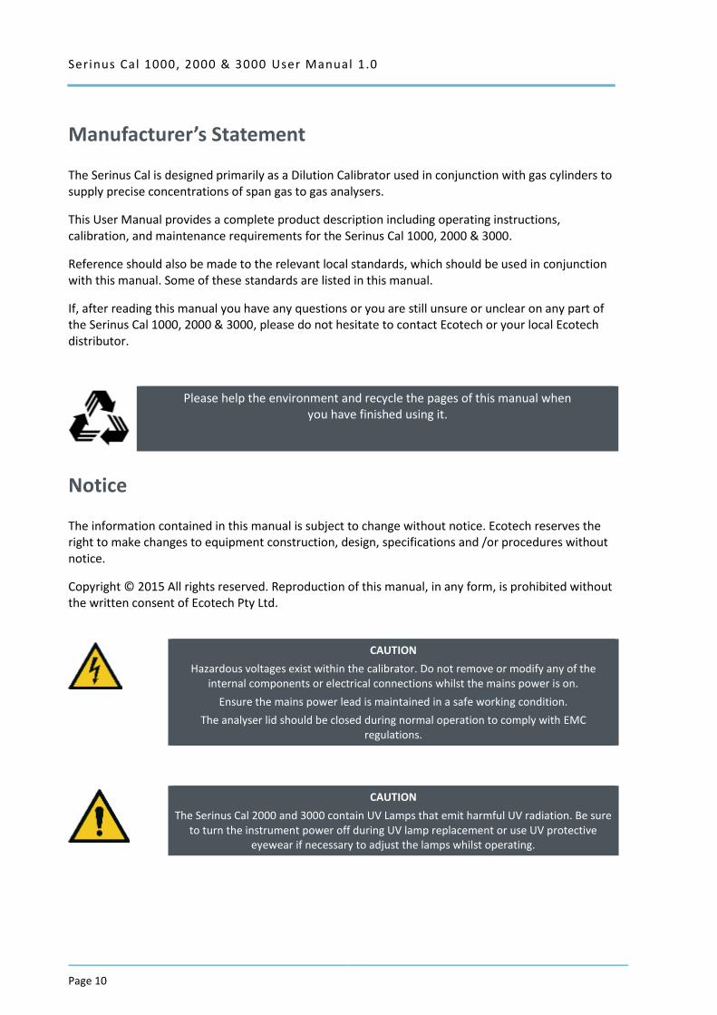
Manufacturer’s Statement
The Serinus Cal is designed primarily as a Dilution Calibrator used in conjunction with gas cylinders to supply precise concentrations of span gas to gas analysers.
This User Manual provides a complete product description including operating instructions, calibration, and maintenance requirements for the Serinus Cal 1000, 2000 & 3000.
Reference should also be made to the relevant local standards, which should be used in conjunction with this manual. Some of these standards are listed in this manual.
If, after reading this manual you have any questions or you are still unsure or unclear on any part of the Serinus Cal 1000, 2000 & 3000, please do not hesitate to contact Ecotech or your local Ecotech distributor.
Please help the environment and recycle the pages of this manual when you have finished using it.
Notice
The information contained in this manual is subject to change without notice. Ecotech reserves the right to make changes to equipment construction, design, specifications and /or procedures without notice.
Copyright © 2015 All rights reserved. Reproduction of this manual, in any form, is prohibited without the written consent of Ecotech Pty Ltd.
CAUTION
Hazardous voltages exist within the calibrator. Do not remove or modify any of the internal components or electrical connections whilst the mains power is on.
Ensure the mains power lead is maintained in a safe working condition.
The analyser lid should be closed during normal operation to comply with EMC regulations.
CAUTION
The Serinus Cal 2000 and 3000 contain UV Lamps that emit harmful UV radiation. Be sure to turn the instrument power off during UV lamp replacement or use UV protective
eyewear if necessary to adjust the lamps whilst operating.
Serinus Cal 1000, 2000 & 3000 User Manual 1.0 Page 11
Safety Requirements
To reduce the risk of personal injury caused by electrical shock, follow all safety notices and warnings in this manual.
If the equipment is used for purposes not specified by Ecotech, the protection provided by this equipment may be impaired.
The safety of any system incorporating the equipment is the responsibility of the assembler of the system.
Replacement of any part should only be carried out by qualified personnel, using only parts specified by Ecotech as these parts meet stringent Ecotech quality assurance standards. Always disconnect power source before removing or replacing any non-consumable components.
Warranty
This product has been manufactured in an ISO 9001/ISO 4801 facility with care and attention to quality.
The product is subject to a two year warranty period on parts and labour from date of shipment (the warranty period). The warranty period commences when the product is shipped from the factory. Lamps and consumable items are not covered by this warranty.
Each calibrator is subjected to a vigorous testing procedure prior to despatch and will be accompanied with a parameter list and a multipoint calibration check thereby enabling the calibrator to be installed and ready for use without any further testing.
Serinus Cal 1000, 2000 & 3000 User Manual 1.0
Page 12
Service and Repairs
Our qualified and experienced technicians are available to provide fast and friendly service between the hours of 8:30am – 5:00pm AEST Monday to Friday. You are welcome to speak to a service technician regarding any questions you have about your calibrator.
Service Guidelines
This manual is designed to provide the necessary information for the setup, operation, testing, maintenance, and troubleshooting of your instrument.
Should you still require support after consulting the documentation, we encourage you to contact your local distributor for support.
To contact Ecotech directly, please e-mail our Technical Support Services group at [email protected] or to speak with someone directly:-
Please dial 1300 364 946 if calling from within Australia
Please dial +61 3 9730 7800 if calling from outside of Australia
Please contact us and obtain a Return Material Authorization (RMA) number before sending any equipment back to the factory. This allows us to track and schedule service work and to expedite customer service. Please include this RMA number when you return equipment, preferably both inside and outside the shipping packaging. This will ensure you receive prompt service.
When shipping instrumentation, please also include the following information:
Name and phone number
Company name
Shipping address
Quantity of items being returned
Model number/s or a description of each item
Serial number/s of each item (if applicable)
A description of the problem
Original sales order or invoice number related to the equipment
Shipping Address:
Attention Service Department
Ecotech Pty Ltd
1492 Ferntree Gully Road,
Knoxfield, VIC, Australia 3180

Serinus Cal 1000, 2000 & 3000 User Manual 1.0 Page 13
CE Mark Declaration of Conformity
This declaration applies to the Serinus Cal1000 series Gas Calibrators as manufactured by Ecotech Pty. Ltd. of 1492 Ferntree Gully Rd, Knoxfield, VIC, Australia.3180.
This declaration relates is in conformity with the following European Union Directives:
Council Directive of 15 December 2004 on the approximation of the laws of Member States relating to electromagnetic compatibility (2004/108/EC)
The following standard was applied:
EN 61326-1:2013 Electrical Equipment for measurement, control and laboratory use – EMC Requirements – Part 1: General requirements.
Immunity Requirements EN61326-1
Electromagnetic compatibility EN61326-1
Council Directive of 12 December 2006 on the harmonization of the laws of Member States relating to electrical equipment designed for use within certain voltage limits (2006/95/EC).
The following standard was applied:
EN 61010-1:2013 Safety requirements for electrical equipment, for measurement control and laboratory use (3rd edition) – Part 1: General requirements
Council Directive of 9 March 1999 Radio Equipment and Telecommunications Terminal Equipment and the mutual recognition of their conformity (R&TTE 1999/5/EC).
The following standard was applied:
EN 300 328 V1.7.1:2006 Electromagnetic compatibility and Radio spectrum Matters (ERM); Wideband transmission systems; Data transmission equipment operating in the 2.4GHz ISM band and using wide band modulation techniques.
Serinus Cal 1000, 2000 & 3000 User Manual 1.0
Page 14
Claims for Damaged Shipments and Shipping Discrepancies
Damaged Shipments
Inspect all instruments thoroughly on receipt. Check materials in the container/s against the enclosed packing list. If the contents are damaged and/or the instrument fails to operate properly, notify the carrier and Ecotech immediately.
The following documents are necessary to support claims:
Original freight bill and bill of lading.
Original invoice or photocopy of original invoice.
Copy of packing list.
Photographs of damaged equipment and container.
You may want to keep a copy of these documents for your records.
Please refer to the instrument name, model number, serial number, sales order number, and your purchase order number on all claims.
You should also:
Contact you freight forwarder for an insurance claim.
Retain packing material for insurance inspection.
Shipping Discrepancies
Check all packages against the packing list immediately on receipt. If a shortage or other discrepancy is found, notify the carrier and Ecotech immediately. We will not be responsible for shortages against the packing list unless they are reported promptly (within 7 days).
Contact Details
Head Office 1492 Ferntree Gully Road, Knoxfield VIC Australia 3180 Phone: +61 (0)3 9730 7800 Fax: +61 (0)3 9730 7899 Email: [email protected] Service: [email protected] International Support: [email protected] www.ecotech.com

Serinus Cal 1000, 2000 & 3000 User Manual 1.0 Page 15
Internationally Recognised Symbols on Ecotech Equipment
On (Supply)
IEC 417, No. 5007
Off (Supply) IEC 417, No. 5008
Protective conductor terminal IEC 60417-5017
Alternating current IEC 60417-5032
Caution! Hot surface IEC 60417-5041
Caution! Risk of danger. Refer to accompanying documentation in all cases where this symbol is marked
ISO 7000-0434
Caution! Risk of electric shock ISO 3864-5036
Serinus Cal 1000, 2000 & 3000 User Manual 1.0
Page 16
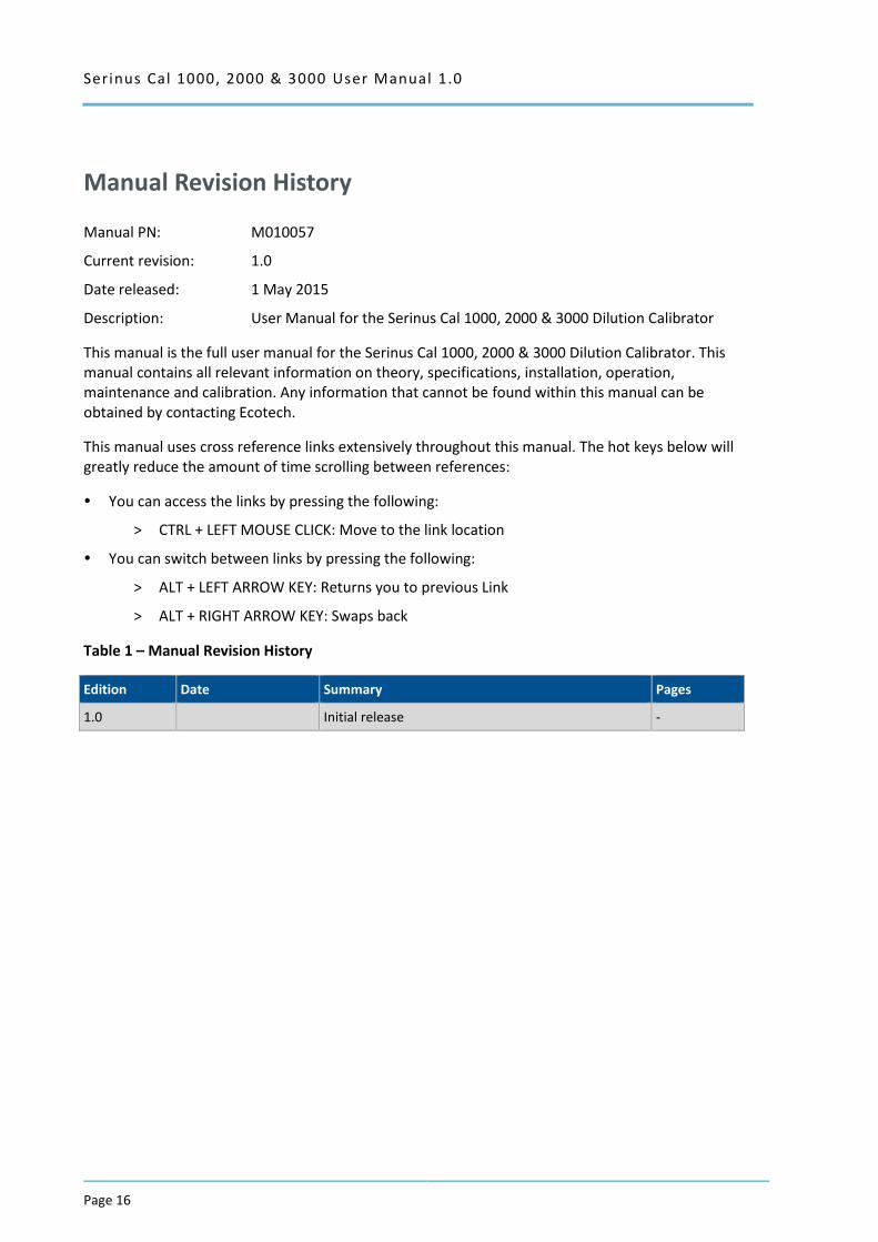
Manual Revision History
Manual PN: M010057
Current revision: 1.0
Date released: 1 May 2015
Description: User Manual for the Serinus Cal 1000, 2000 & 3000 Dilution Calibrator
This manual is the full user manual for the Serinus Cal 1000, 2000 & 3000 Dilution Calibrator. This manual contains all relevant information on theory, specifications, installation, operation, maintenance and calibration. Any information that cannot be found within this manual can be obtained by contacting Ecotech.
This manual uses cross reference links extensively throughout this manual. The hot keys below will greatly reduce the amount of time scrolling between references:
You can access the links by pressing the following:
> CTRL + LEFT MOUSE CLICK: Move to the link location
You can switch between links by pressing the following:
> ALT + LEFT ARROW KEY: Returns you to previous Link
> ALT + RIGHT ARROW KEY: Swaps back
Table 1 – Manual Revision History
Edition Date Summary Pages
1.0 Initial release -
Serinus Cal 1000, 2000 & 3000 User Manual 1.0 Page 17
1 Introduction
1.1 Description
The Serinus Cal has been designed as a stand-alone dilution calibrator specifically for environmental applications and should give many years of trouble free service provided that it is installed, used and maintained correctly.
It can be used in conjunction with many different analysers measuring gases such as CO, CO2, O3, NOx, NOy, NH3 and SO2 to provide precise and constant volumes of zero air or dilutions of various calibration gases.
The Serinus Cal is used in conjunction with regulatory traceable gases, and zero air generators. The Serinus Cal 2000 provides the additional feature of an ozone generator so that it can produce O3 to be used when performing a Gas Phase Titration (GPT). The Serinus Cal 3000 includes an ozone generator as well as an ozone photometer for the accurate creation and delivery of ozone concentrations for use when calibrating O3 analysers.
This section will describe the specifications of the calibrator as well as the main components and techniques used to provide stable gas concentrations.
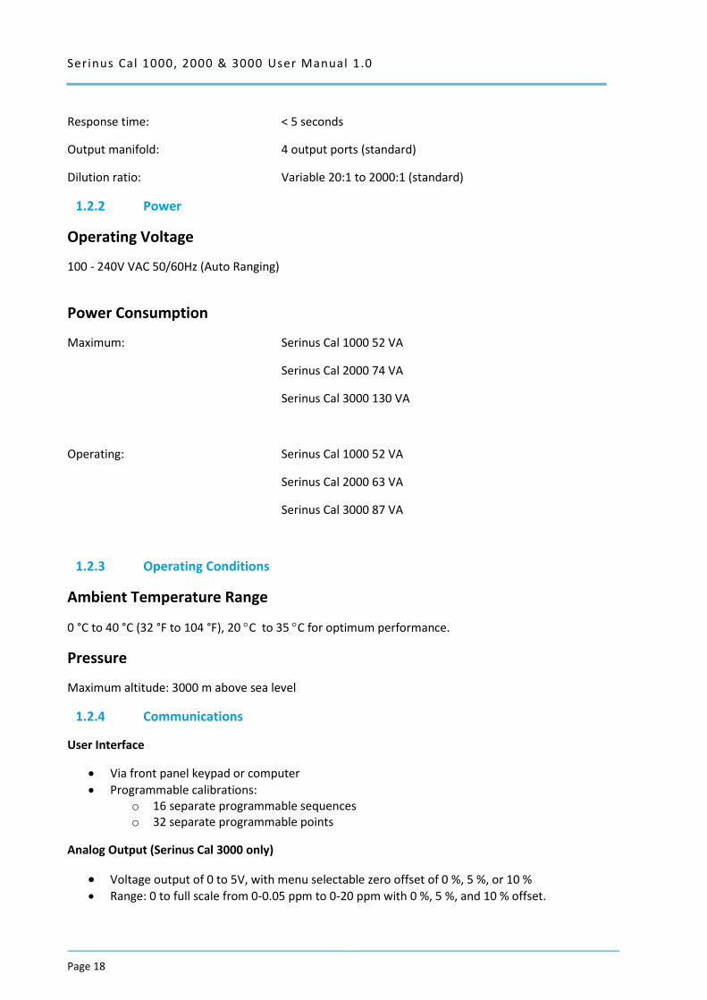
1.2 Specifications
1.2.1 Dilution & Span Flows
Range
Input dilution gases: 1 port (standard) 120-180 kPa (g)
2 ports (optional) 120-180 kPa (g)
Input source gases: 1 to 4 (standard) 100-300 kPa (g)
1 to 8 (optional) 100-300 kPa (g)
Dilution mass flow controller: 0-10 slpm, (STD 0°C, 1.000 ATM) (standard)
0-1, 0-2, 0-5 or 0-20 slpm (optional)
Source mass flow controller: 0-50 sccm (STD 0°C, 1.000 ATM) (standard)
0-10 sccm, 0-20 sccm, 0-100 sccm, 0-200 sccm, 0-500 sccm, 0-1000 sccm, 0-2 slpm or 0-5 slpm (optional)
Flow accuracy (constant temp): Within 1 % of full scale
Flow repeatability: Within 0.15 % of full scale
Linearity: Within 0.15 % of full scale
Operating gas pressure: 100-200 kPa
Zero drift: < 0.58 % per year
Serinus Cal 1000, 2000 & 3000 User Manual 1.0
Page 18
Response time: < 5 seconds
Output manifold: 4 output ports (standard)
Dilution ratio: Variable 20:1 to 2000:1 (standard)
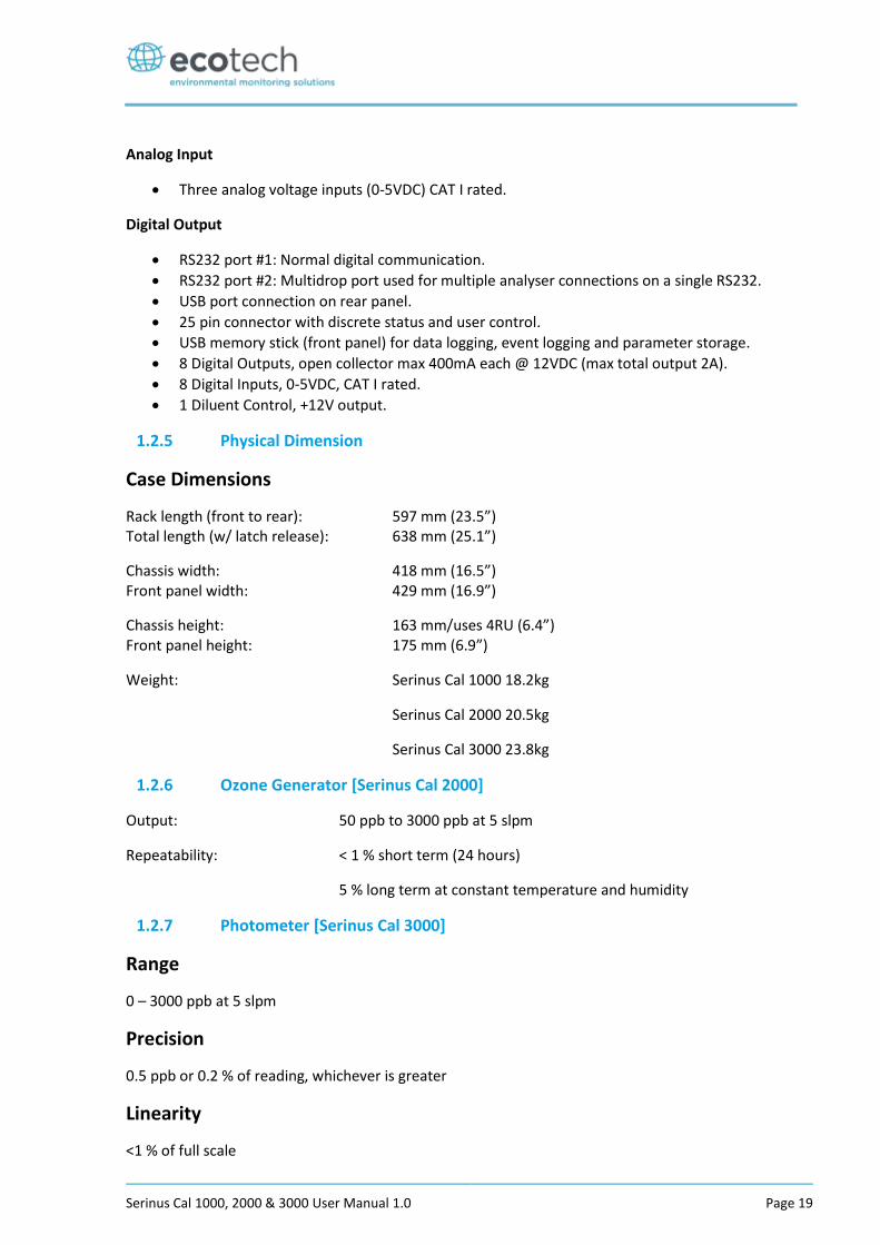
1.2.2 Power
Operating Voltage
100 - 240V VAC 50/60Hz (Auto Ranging)
Power Consumption
Maximum: Serinus Cal 1000 52 VA
Serinus Cal 2000 74 VA
Serinus Cal 3000 130 VA
Operating: Serinus Cal 1000 52 VA
Serinus Cal 2000 63 VA
Serinus Cal 3000 87 VA
1.2.3 Operating Conditions
Ambient Temperature Range
0 °C to 40 °C (32 °F to 104 °F), 20 C to 35 C for optimum performance.
Pressure
Maximum altitude: 3000 m above sea level
1.2.4 Communications
User Interface
Via front panel keypad or computer
Programmable calibrations: o 16 separate programmable sequences o 32 separate programmable points
Analog Output (Serinus Cal 3000 only)
Voltage output of 0 to 5V, with menu selectable zero offset of 0 %, 5 %, or 10 % Range: 0 to full scale from 0-0.05 ppm to 0-20 ppm with 0 %, 5 %, and 10 % offset.
Serinus Cal 1000, 2000 & 3000 User Manual 1.0 Page 19
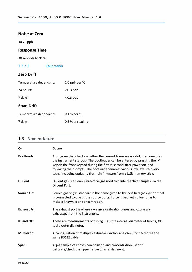
Analog Input
Three analog voltage inputs (0-5VDC) CAT I rated.
Digital Output
RS232 port #1: Normal digital communication.
RS232 port #2: Multidrop port used for multiple analyser connections on a single RS232.
USB port connection on rear panel.
25 pin connector with discrete status and user control.
USB memory stick (front panel) for data logging, event logging and parameter storage.
8 Digital Outputs, open collector max 400mA each @ 12VDC (max total output 2A).
8 Digital Inputs, 0-5VDC, CAT I rated.
1 Diluent Control, +12V output.
1.2.5 Physical Dimension
Case Dimensions
Rack length (front to rear): 597 mm (23.5”) Total length (w/ latch release): 638 mm (25.1”)
Chassis width: 418 mm (16.5”) Front panel width: 429 mm (16.9”)
Chassis height: 163 mm/uses 4RU (6.4”) Front panel height: 175 mm (6.9”)
Weight: Serinus Cal 1000 18.2kg
Serinus Cal 2000 20.5kg
Serinus Cal 3000 23.8kg
1.2.6 Ozone Generator [Serinus Cal 2000]
Output: 50 ppb to 3000 ppb at 5 slpm
Repeatability: < 1 % short term (24 hours)
5 % long term at constant temperature and humidity
1.2.7 Photometer [Serinus Cal 3000]
Range
0 – 3000 ppb at 5 slpm
Precision
0.5 ppb or 0.2 % of reading, whichever is greater
Linearity
<1 % of full scale
Serinus Cal 1000, 2000 & 3000 User Manual 1.0
Page 20
Noise at Zero
<0.25 ppb
Response Time
30 seconds to 95 %
1.2.7.1 Calibration
Zero Drift
Temperature dependant: 1.0 ppb per °C
24 hours: < 0.3 ppb
7 days: < 0.3 ppb
Span Drift
Temperature dependant: 0.1 % per °C
7 days: 0.5 % of reading
1.3 Nomenclature
O3 Ozone
Bootloader: A program that checks whether the current firmware is valid, then executes the instrument start-up. The bootloader can be entered by pressing the ‘+’ key on the front keypad during the first ½ second after power on, and following the prompts. The bootloader enables various low level recovery tools, including updating the main firmware from a USB memory stick.
Diluent Diluent gas is a clean, unreactive gas used to dilute reactive samples via the Diluent Port.
Source Gas Source gas or gas standard is the name given to the certified gas cylinder that is connected to one of the source ports. To be mixed with diluent gas to make a known span concentration.
Exhaust Air The exhaust port is where excessive calibration gases and ozone are exhausted from the instrument.
ID and OD: These are measurements of tubing. ID is the internal diameter of tubing, OD is the outer diameter.
Multidrop: A configuration of multiple calibrators and/or analysers connected via the same RS232 cable.
Span: A gas sample of known composition and concentration used to calibrate/check the upper range of an instrument.
Serinus Cal 1000, 2000 & 3000 User Manual 1.0 Page 21
Zero: Zero air to calibrate/check the lower range of an instrument.
Point: A single operation such as a dilution.
Sequence: A group of operations.
Background Is the reading of the instrument without ozone present in the measurement cell. In the case of the Serinus Cal 3000, the background measurement is performed using zero air.
Calibration: The process of adjusting an instrument to ensure that it is measuring the correct concentration.
Zero Drift: The change in instrument response to zero air over a period of continuous unadjusted operation.
Zero Air Is purified air in which contaminants are removed to a level below what is detectable by the instruments used within the system. In a typical ambient air monitoring station this normally includes water vapour, hydrocarbons, O3, NO, NO2, SO2, H2S and CO
PCA: Printed Circuit Assembly. An electronic circuit mounted on a printed circuit board to perform a specific electronic function.
Slpm: Standard litres per minute. This is the flow referenced to standard temperature and pressure conditions. For the purposes of this manual, all flows are referenced to 0 °C and 101.3 kpa (1 atm).
GPT: Gas Phase Titration.
1.4 Background/Theory
1.4.1 Dilution Theory
The Serinus Cal operates on the principle that when a known quantity of source gas is measured with a known quantity of diluent gas, the resultant mixture can be calculated. The assumption relies on the conservation of mass which occurs if there is no loss of the source gas via chemical reaction between the source component gas(es) and the diluent gas. In that case we can write that for each compound (i), the mass (m), entering the system is equal to the mass exiting the system:
𝑚𝑖|𝑖𝑛 = 𝑚𝑖|𝑜𝑢𝑡
In other words,
𝐶𝑜𝑛𝑐𝑒𝑛𝑡𝑟𝑎𝑡𝑖𝑜𝑛𝑖|𝑖𝑛 × 𝐹𝑙𝑜𝑤𝑅𝑎𝑡𝑒𝑖|𝑖𝑛 = 𝐶𝑜𝑛𝑐𝑒𝑛𝑡𝑟𝑎𝑡𝑖𝑜𝑛𝑖|𝑜𝑢𝑡 × 𝐹𝑙𝑜𝑤𝑅𝑎𝑡𝑒𝑖|𝑜𝑢𝑡
Serinus Cal 1000, 2000 & 3000 User Manual 1.0
Page 22
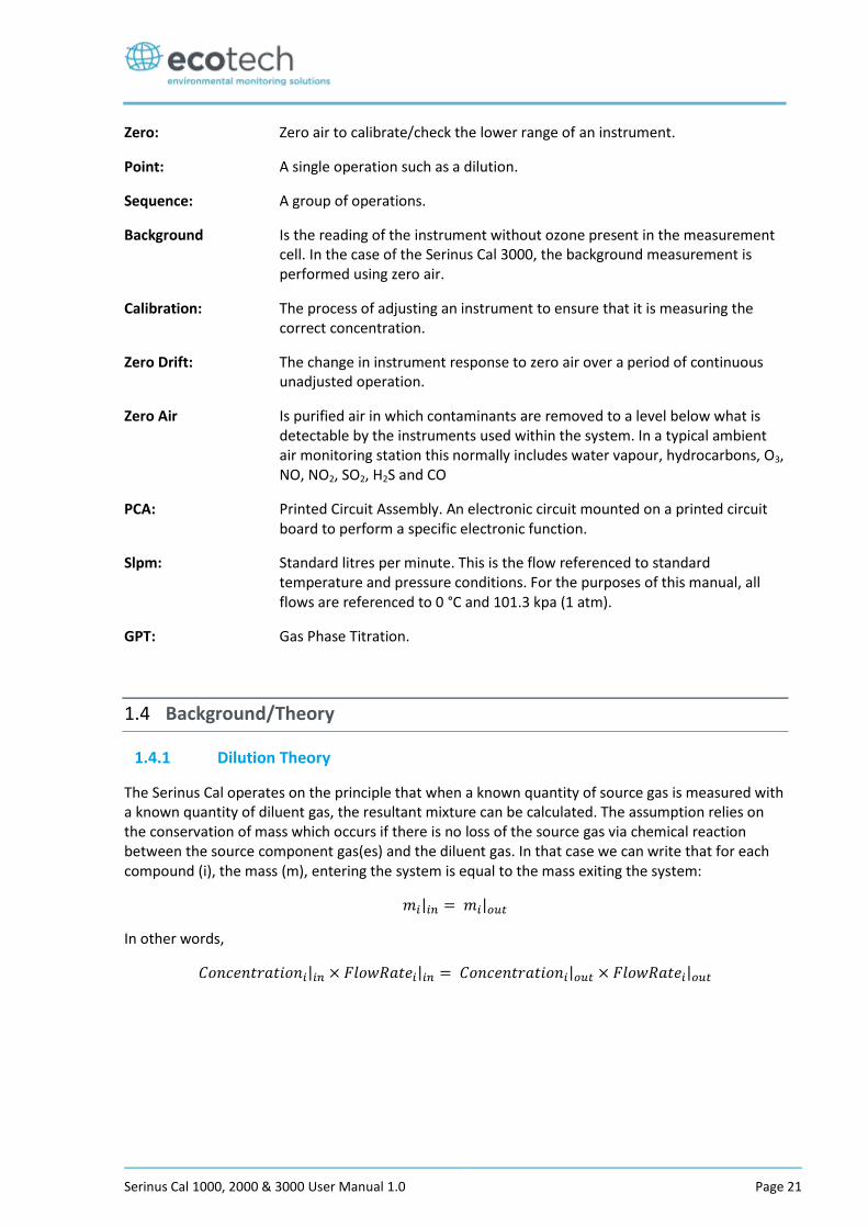
Figure 1 – Dilution Theory for Serinus Cal
So, according to the mass balance and considering Figure 1:
𝐶𝑠𝑜𝑢𝑟𝑐𝑒 × 𝐹𝑠𝑜𝑢𝑟𝑐𝑒 + 𝐶𝑑𝑖𝑙𝑢𝑒𝑛𝑡 × 𝐹𝑑𝑖𝑙𝑢𝑒𝑛𝑡 = 𝐶𝑜𝑢𝑡𝑝𝑢𝑡 × 𝐹𝑜𝑢𝑡𝑝𝑢𝑡
Where 𝐶𝑖 = Concentration
𝐹𝑖 = Mass flow rate
As the diluent is always chosen as a “chemical free gas”, the term 𝐶𝑑𝑖𝑙𝑢𝑒𝑛𝑡 is always zero. This simplifies the equation to:
𝐶𝑠𝑜𝑢𝑟𝑐𝑒 × 𝐹𝑠𝑜𝑢𝑟𝑐𝑒 = 𝐶𝑜𝑢𝑡𝑝𝑢𝑡 × 𝐹𝑜𝑢𝑡𝑝𝑢𝑡
Since we also know that the total mass flow rate is also conserved:
𝐹𝑜𝑢𝑡𝑝𝑢𝑡 = 𝐹𝑠𝑜𝑢𝑟𝑐𝑒 + 𝐹𝑑𝑖𝑙𝑢𝑒𝑛𝑡
The equation becomes:
𝐶𝑠𝑜𝑢𝑟𝑐𝑒 × 𝐹𝑠𝑜𝑢𝑟𝑐𝑒 = 𝐶𝑜𝑢𝑡𝑝𝑢𝑡 × (𝐹𝑜𝑢𝑡𝑝𝑢𝑡 + 𝐹𝑑𝑖𝑙𝑢𝑒𝑛𝑡)
This can be rearranged to give:
𝐶𝑜𝑢𝑡𝑝𝑢𝑡 =𝐶𝑠𝑜𝑢𝑟𝑐𝑒 × 𝐹𝑠𝑜𝑢𝑟𝑐𝑒
𝐹𝑠𝑜𝑢𝑟𝑐𝑒 + 𝐹𝑑𝑖𝑙𝑢𝑒𝑛𝑡
This is the governing equation used in the operation of the Serinus Cal.
The mass flow rates of the source gas and diluent gases are accurately measured using mass flow controllers. Suppliers usually certify the source gas cylinder concentration, allowing the concentration of the output to be calculated easily.
1.4.2 Ozone Photometer Theory [Serinus Cal 3000]
This section outlines the relevant theory for Serinus Cal 3000 which contains an ozone (O3) photometer and ozone generator.
The photometer accurately measures and controls the ozone concentration generated by an internal generator, allowing its use as a transfer standard to calibrate ozone analysers.
The Serinus Cal follows these principles and measurement techniques:
Ozone shows strong absorption of UV light at 254 nm.
Diluent air is passed into the glass absorption tube (Optical Cell).
Serinus Cal 1000, 2000 & 3000 User Manual 1.0 Page 23
Within the photometer, a single beam of UV radiation (from a mercury vapour lamp) passes through the sample and is absorbed by the ozone.
The solar blind vacuum photodiode detects any UV light that is not absorbed.
The strength of the UV light signal being detected is proportional to the amount of UV light being absorbed by ozone.
The Serinus Cal uses the Beer-Lambert relationship (Appendix D) to calculate the ozone concentration.
O3 is not the only gas that absorbs UV (254 nm), SO2 and aromatic compounds also absorb radiation at this wavelength. To eliminate these interferences a second cycle (referred to as the reference cycle) is performed with zero air from the diluents port. This reference signal is removed from the sample measurement signal. This enables the accurate measurement of ozone without the influence of interferent.
The main controller PCA contains electronics to measure, and correct for all the major external variables to ensure stable and reliable operation.
Note: In order to obtain the desired stability levels necessary for ozone analyser calibrations, the user should run the Serinus Cal 3000 at the same ozone concentration for at least 30 minutes to obtain a sufficiently stable
output.
1.4.3 Explanation Photometer Transfer Standards
In ambient air monitoring applications, precise ozone concentrations called standards are required for the calibration of ozone analysers. Due to the instability of ozone, concentrations must be generated and “verified” on site with another instrument referred to as a transfer standard.
A transfer standard is defined as a transportable device or apparatus which is capable of accurately reproducing ozone.
The transfer standard’s purpose is to transfer the authority of a Level 1 pollutant standard to a remote point where it is used to verify or calibrate an air monitoring analyser.
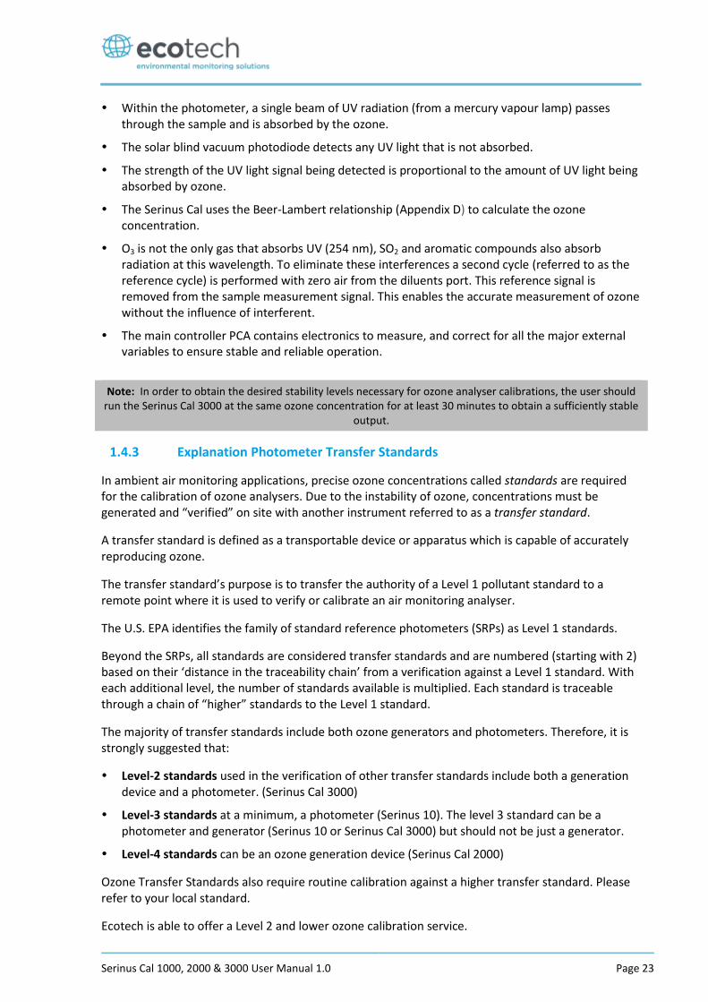
The U.S. EPA identifies the family of standard reference photometers (SRPs) as Level 1 standards.
Beyond the SRPs, all standards are considered transfer standards and are numbered (starting with 2) based on their ‘distance in the traceability chain’ from a verification against a Level 1 standard. With each additional level, the number of standards available is multiplied. Each standard is traceable through a chain of “higher” standards to the Level 1 standard.
The majority of transfer standards include both ozone generators and photometers. Therefore, it is strongly suggested that:
Level-2 standards used in the verification of other transfer standards include both a generation device and a photometer. (Serinus Cal 3000)
Level-3 standards at a minimum, a photometer (Serinus 10). The level 3 standard can be a photometer and generator (Serinus 10 or Serinus Cal 3000) but should not be just a generator.
Level-4 standards can be an ozone generation device (Serinus Cal 2000)
Ozone Transfer Standards also require routine calibration against a higher transfer standard. Please refer to your local standard.
Ecotech is able to offer a Level 2 and lower ozone calibration service.
Serinus Cal 1000, 2000 & 3000 User Manual 1.0
Page 24
Figure 2 – Ozone Transfer Standard Hierarchy
1.5 Instrument Description
1.5.1 Common Components
In this section we describe the components that are common to all Serinus Cal models.
1.5.1.1 Main Controller PCA
The main controller PCA controls all the processes within the instrument. As well as the on-board microprocessor, it contains a battery backed clock-calendar, analog to digital converters and many other circuits for signal processing and control. The ambient pressure and chassis temperature sensors are also located on this board. The main controller PCA is located above all other components within the analyser. It pivots on hinges to allow access to the components underneath.
CAUTION
Never place objects on top of the main controller PCA as it may result in damage.
Serinus Cal 1000, 2000 & 3000 User Manual 1.0 Page 25
1.5.1.2 Rear Panel PCA
The rear panel PCA contains all the communications connections for the user through the rear panel. This PCA also controls all the internal solenoid bullet valves as well as the Diluent control. This PCA has its own power connection directly from main controller PCA.
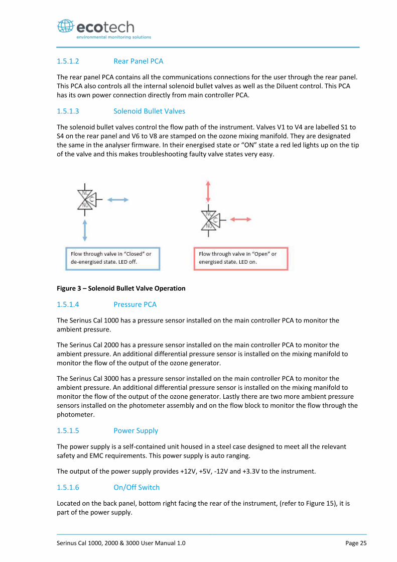
1.5.1.3 Solenoid Bullet Valves
The solenoid bullet valves control the flow path of the instrument. Valves V1 to V4 are labelled S1 to S4 on the rear panel and V6 to V8 are stamped on the ozone mixing manifold. They are designated the same in the analyser firmware. In their energised state or “ON” state a red led lights up on the tip of the valve and this makes troubleshooting faulty valve states very easy.
Figure 3 – Solenoid Bullet Valve Operation
1.5.1.4 Pressure PCA
The Serinus Cal 1000 has a pressure sensor installed on the main controller PCA to monitor the ambient pressure.
The Serinus Cal 2000 has a pressure sensor installed on the main controller PCA to monitor the ambient pressure. An additional differential pressure sensor is installed on the mixing manifold to monitor the flow of the output of the ozone generator.
The Serinus Cal 3000 has a pressure sensor installed on the main controller PCA to monitor the ambient pressure. An additional differential pressure sensor is installed on the mixing manifold to monitor the flow of the output of the ozone generator. Lastly there are two more ambient pressure sensors installed on the photometer assembly and on the flow block to monitor the flow through the photometer.
1.5.1.5 Power Supply
The power supply is a self-contained unit housed in a steel case designed to meet all the relevant safety and EMC requirements. This power supply is auto ranging.
The output of the power supply provides +12V, +5V, -12V and +3.3V to the instrument.
1.5.1.6 On/Off Switch
Located on the back panel, bottom right facing the rear of the instrument, (refer to Figure 15), it is part of the power supply.
Serinus Cal 1000, 2000 & 3000 User Manual 1.0
Page 26
1.5.1.7 MFC
A mass flow controller (MFC) is a device that is used to measure and control the flow of gases at a particular flow rate. It is controlled by the main controller PCA and is used to give the user the desired output concentration as defined in the point setup. There are 2 MFC in each Serinus Cal as standard regardless on the model. There are two optional MFC’s available, a second Diluent MFC and a second Source MFC.
1.5.1.8 DFU
A disposable filter unit (DFU) is used to protect the MFC’s and other pneumatic system components from a build-up of particulate matter.
1.5.1.9 Output Manifold
The output manifold is a common set of ports used as the conduit for delivering the final user defined diluted gas concentration to its final destination. When the gas leaves the calibrator it will be at ambient pressure. This is achieved by always allocating one of the 4 common ports as a vent leading to atmosphere.
Serinus Cal 1000, 2000 & 3000 User Manual 1.0 Page 27
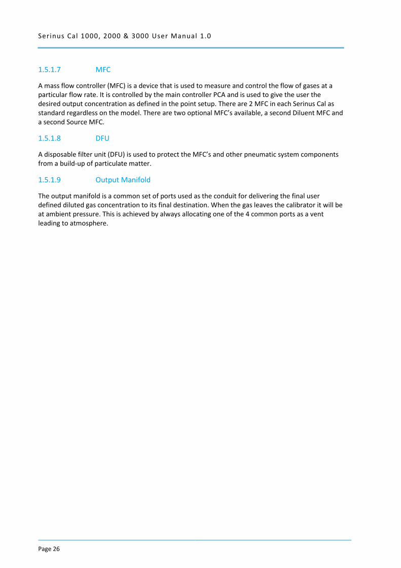
1.5.2 Serinus Cal 1000 Components
The Serinus Cal 1000 is a stand-alone dilution calibrator designed specifically for environmental applications. The Serinus Cal 1000 can be used in conjunction with many different gas analysers and provides precise and constant volumes of zero air or dilutions of various span gases.
Figure 4 – Serinus Cal 1000 Layout
Serinus Cal 1000, 2000 & 3000 User Manual 1.0
Page 28
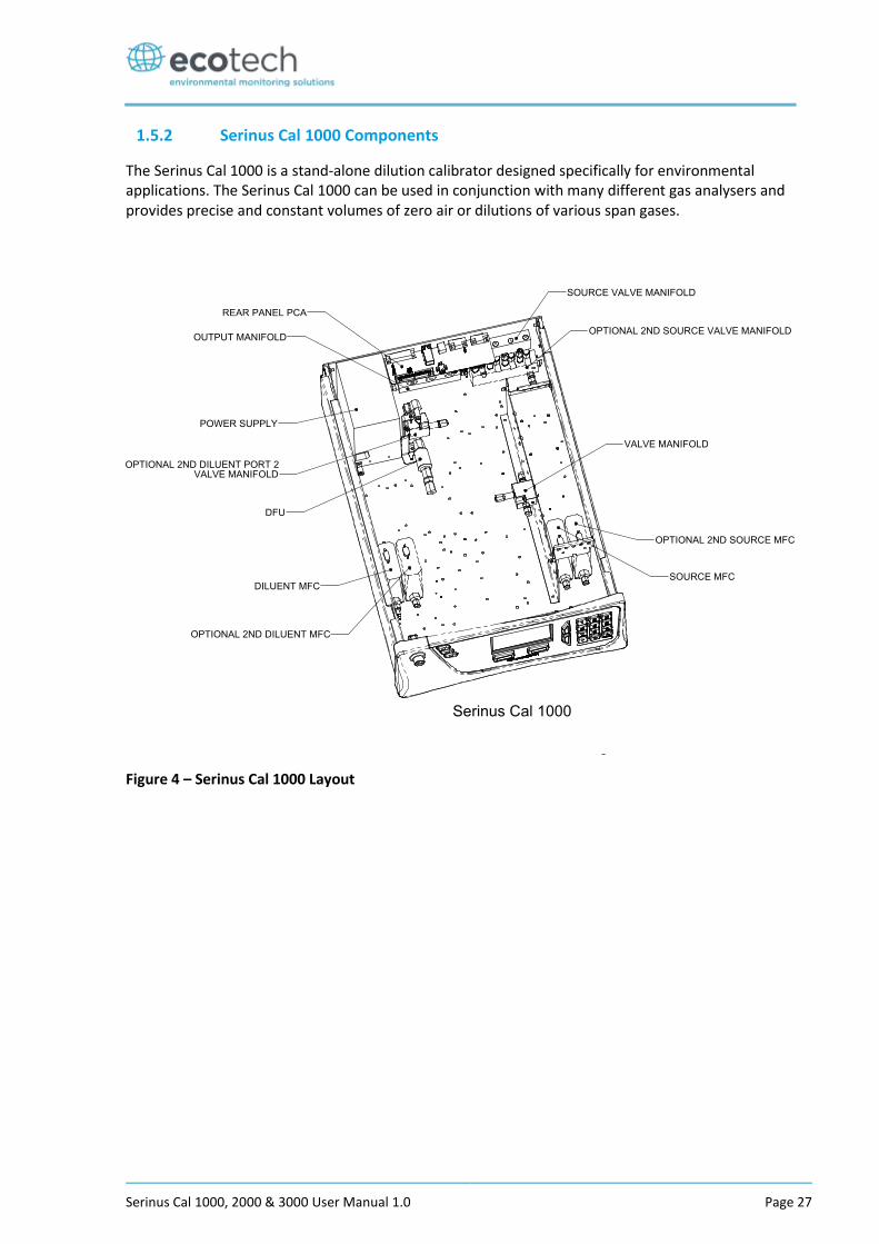
1.5.3 Serinus Cal 2000 Components
The Serinus Cal 2000 provides an additional ozone generator. This allows the Serinus Cal 2000 to run GPT calibrations of ozone with precise dilution rates. There are a few structural changes compared to the Serinus Cal 1000 to incorporate the option.
Figure 5 – Serinus Cal 2000 Layout
Serinus Cal 1000, 2000 & 3000 User Manual 1.0 Page 29
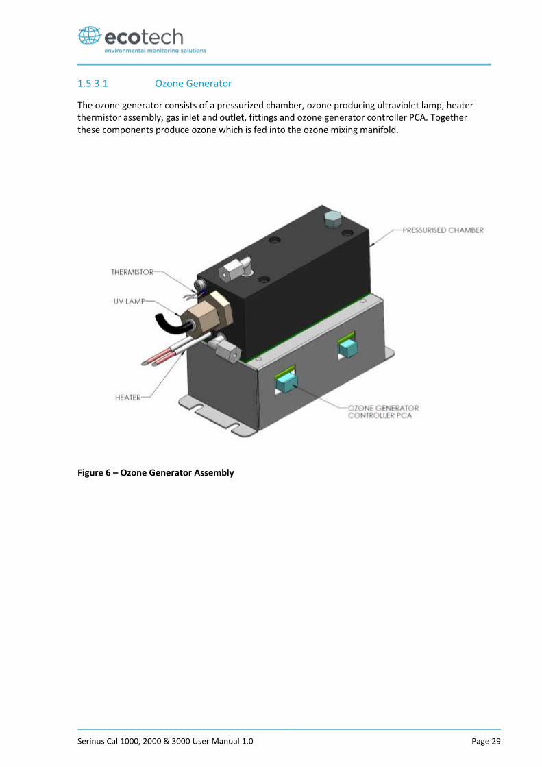
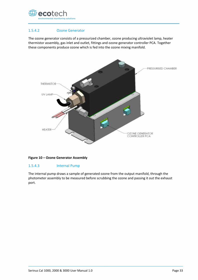
1.5.3.1 Ozone Generator
The ozone generator consists of a pressurized chamber, ozone producing ultraviolet lamp, heater thermistor assembly, gas inlet and outlet, fittings and ozone generator controller PCA. Together these components produce ozone which is fed into the ozone mixing manifold.
Figure 6 – Ozone Generator Assembly
Serinus Cal 1000, 2000 & 3000 User Manual 1.0
Page 30
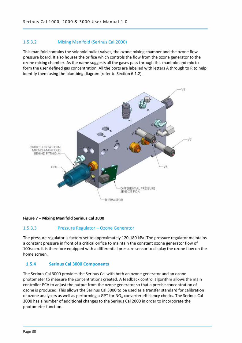
1.5.3.2 Mixing Manifold (Serinus Cal 2000)
This manifold contains the solenoid bullet valves, the ozone mixing chamber and the ozone flow pressure board. It also houses the orifice which controls the flow from the ozone generator to the ozone mixing chamber. As the name suggests all the gases pass through this manifold and mix to form the user defined gas concentration. All the ports are labelled with letters A through to R to help identify them using the plumbing diagram (refer to Section 6.1.2).
Figure 7 – Mixing Manifold Serinus Cal 2000
1.5.3.3 Pressure Regulator – Ozone Generator
The pressure regulator is factory set to approximately 120-180 kPa. The pressure regulator maintains a constant pressure in front of a critical orifice to maintain the constant ozone generator flow of 100sccm. It is therefore equipped with a differential pressure sensor to display the ozone flow on the home screen.
1.5.4 Serinus Cal 3000 Components
The Serinus Cal 3000 provides the Serinus Cal with both an ozone generator and an ozone photometer to measure the concentrations created. A feedback control algorithm allows the main controller PCA to adjust the output from the ozone generator so that a precise concentration of ozone is produced. This allows the Serinus Cal 3000 to be used as a transfer standard for calibration of ozone analysers as well as performing a GPT for NOX converter efficiency checks. The Serinus Cal 3000 has a number of additional changes to the Serinus Cal 2000 in order to incorporate the photometer function.
Serinus Cal 1000, 2000 & 3000 User Manual 1.0 Page 31
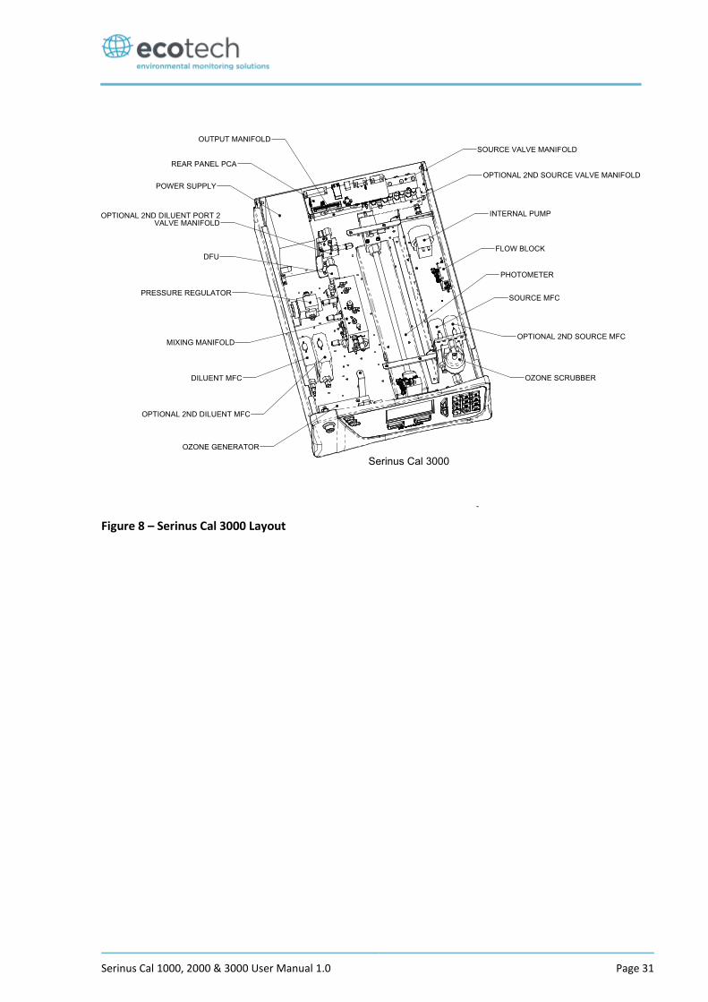
Figure 8 – Serinus Cal 3000 Layout
Serinus Cal 1000, 2000 & 3000 User Manual 1.0
Page 32
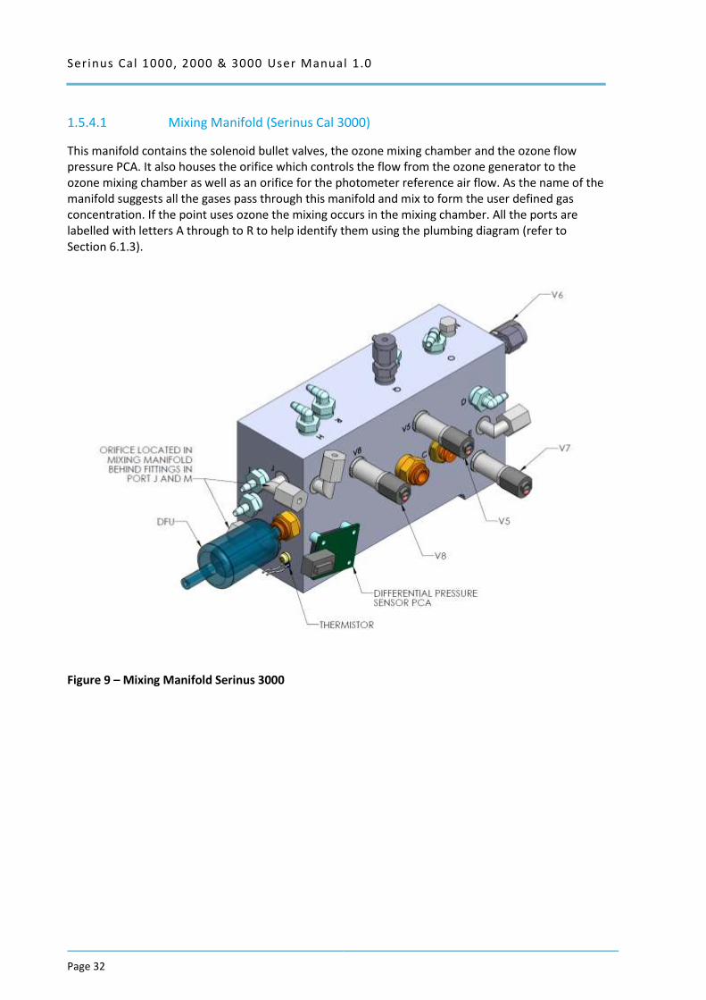
1.5.4.1 Mixing Manifold (Serinus Cal 3000)
This manifold contains the solenoid bullet valves, the ozone mixing chamber and the ozone flow pressure PCA. It also houses the orifice which controls the flow from the ozone generator to the ozone mixing chamber as well as an orifice for the photometer reference air flow. As the name of the manifold suggests all the gases pass through this manifold and mix to form the user defined gas concentration. If the point uses ozone the mixing occurs in the mixing chamber. All the ports are labelled with letters A through to R to help identify them using the plumbing diagram (refer to Section 6.1.3).
Figure 9 – Mixing Manifold Serinus 3000
Serinus Cal 1000, 2000 & 3000 User Manual 1.0 Page 33
1.5.4.2 Ozone Generator
The ozone generator consists of a pressurized chamber, ozone producing ultraviolet lamp, heater thermistor assembly, gas inlet and outlet, fittings and ozone generator controller PCA. Together these components produce ozone which is fed into the ozone mixing manifold.
Figure 10 – Ozone Generator Assembly
1.5.4.3 Internal Pump
The internal pump draws a sample of generated ozone from the output manifold, through the photometer assembly to be measured before scrubbing the ozone and passing it out the exhaust port.
Serinus Cal 1000, 2000 & 3000 User Manual 1.0
Page 34
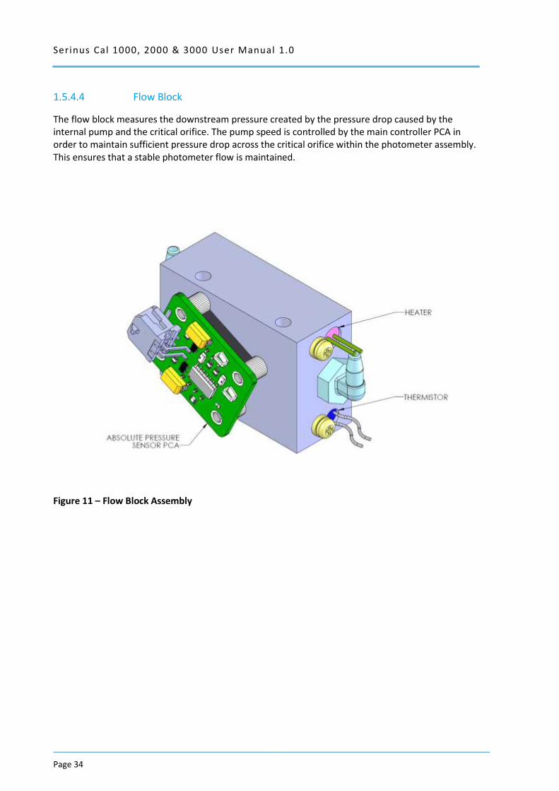
1.5.4.4 Flow Block
The flow block measures the downstream pressure created by the pressure drop caused by the internal pump and the critical orifice. The pump speed is controlled by the main controller PCA in order to maintain sufficient pressure drop across the critical orifice within the photometer assembly. This ensures that a stable photometer flow is maintained.
Figure 11 – Flow Block Assembly
Serinus Cal 1000, 2000 & 3000 User Manual 1.0 Page 35
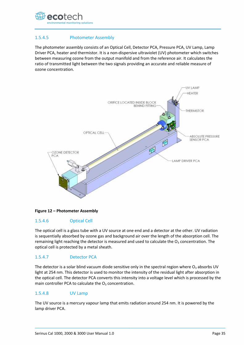
1.5.4.5 Photometer Assembly
The photometer assembly consists of an Optical Cell, Detector PCA, Pressure PCA, UV Lamp, Lamp Driver PCA, heater and thermistor. It is a non-dispersive ultraviolet (UV) photometer which switches between measuring ozone from the output manifold and from the reference air. It calculates the ratio of transmitted light between the two signals providing an accurate and reliable measure of ozone concentration.
Figure 12 – Photometer Assembly
1.5.4.6 Optical Cell
The optical cell is a glass tube with a UV source at one end and a detector at the other. UV radiation is sequentially absorbed by ozone gas and background air over the length of the absorption cell. The remaining light reaching the detector is measured and used to calculate the O3 concentration. The optical cell is protected by a metal sheath.
1.5.4.7 Detector PCA
The detector is a solar blind vacuum diode sensitive only in the spectral region where O3 absorbs UV light at 254 nm. This detector is used to monitor the intensity of the residual light after absorption in the optical cell. The detector PCA converts this intensity into a voltage level which is processed by the main controller PCA to calculate the O3 concentration.
1.5.4.8 UV Lamp
The UV source is a mercury vapour lamp that emits radiation around 254 nm. It is powered by the lamp driver PCA.
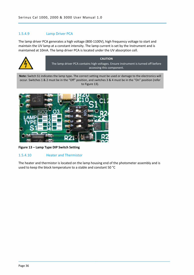
Serinus Cal 1000, 2000 & 3000 User Manual 1.0
Page 36
1.5.4.9 Lamp Driver PCA
The lamp driver PCA generates a high voltage (800-1100V), high frequency voltage to start and maintain the UV lamp at a constant intensity. The lamp current is set by the Instrument and is maintained at 10mA. The lamp driver PCA is located under the UV absorption cell.
CAUTION
The lamp driver PCA contains high voltages. Ensure instrument is turned off before accessing this component.
Note: Switch S1 indicates the lamp type. The correct setting must be used or damage to the electronics will occur. Switches 1 & 2 must be in the “Off” position, and switches 3 & 4 must be in the “On” position (refer
to Figure 13).
Figure 13 – Lamp Type DIP Switch Setting
1.5.4.10 Heater and Thermistor
The heater and thermistor is located on the lamp housing end of the photometer assembly and is used to keep the block temperature to a stable and constant 50 °C
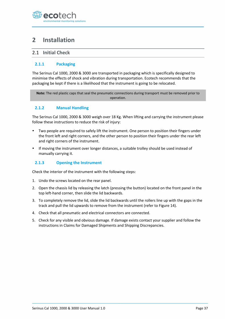
Serinus Cal 1000, 2000 & 3000 User Manual 1.0 Page 37
2 Installation
2.1 Initial Check
2.1.1 Packaging
The Serinus Cal 1000, 2000 & 3000 are transported in packaging which is specifically designed to minimise the effects of shock and vibration during transportation. Ecotech recommends that the packaging be kept if there is a likelihood that the instrument is going to be relocated.
Note: The red plastic caps that seal the pneumatic connections during transport must be removed prior to operation.
2.1.2 Manual Handling
The Serinus Cal 1000, 2000 & 3000 weigh over 18 Kg. When lifting and carrying the instrument please follow these instructions to reduce the risk of injury:
Two people are required to safely lift the instrument. One person to position their fingers under the front left and right corners, and the other person to position their fingers under the rear left and right corners of the instrument.
If moving the instrument over longer distances, a suitable trolley should be used instead of manually carrying it.
2.1.3 Opening the Instrument
Check the interior of the instrument with the following steps:
1. Undo the screws located on the rear panel.
2. Open the chassis lid by releasing the latch (pressing the button) located on the front panel in the top left-hand corner, then slide the lid backwards.
3. To completely remove the lid, slide the lid backwards until the rollers line up with the gaps in the track and pull the lid upwards to remove from the instrument (refer to Figure 14).
4. Check that all pneumatic and electrical connectors are connected.
5. Check for any visible and obvious damage. If damage exists contact your supplier and follow the instructions in Claims for Damaged Shipments and Shipping Discrepancies.
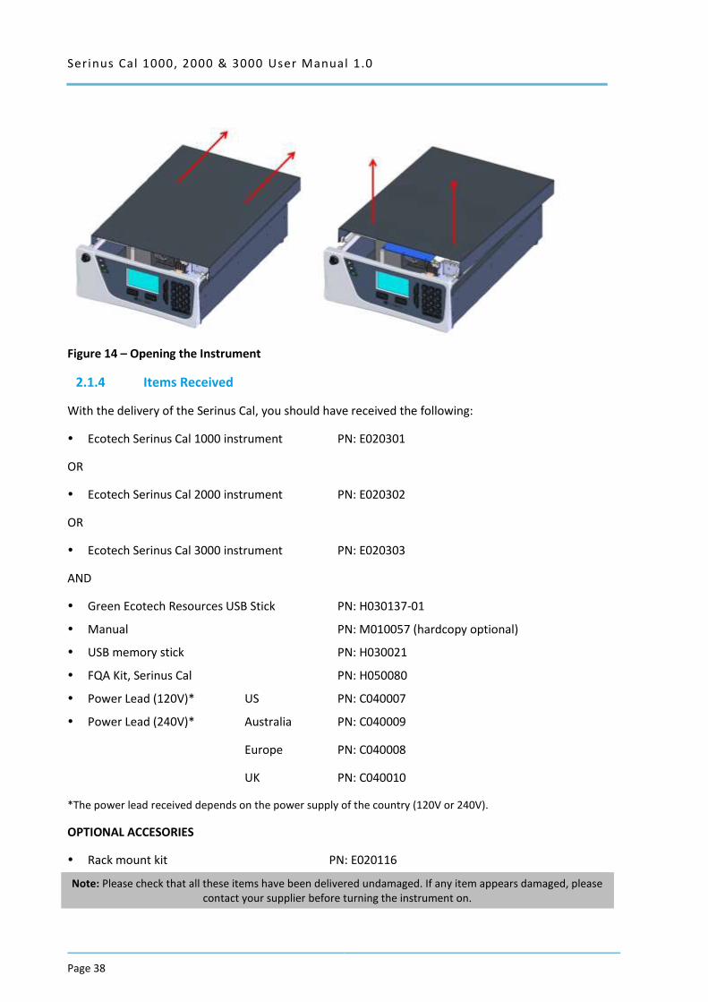
Serinus Cal 1000, 2000 & 3000 User Manual 1.0
Page 38
Figure 14 – Opening the Instrument
2.1.4 Items Received
With the delivery of the Serinus Cal, you should have received the following:
Ecotech Serinus Cal 1000 instrument PN: E020301
OR
Ecotech Serinus Cal 2000 instrument PN: E020302
OR
Ecotech Serinus Cal 3000 instrument PN: E020303
AND
Green Ecotech Resources USB Stick PN: H030137-01
Manual PN: M010057 (hardcopy optional)
USB memory stick PN: H030021
FQA Kit, Serinus Cal PN: H050080
Power Lead (120V)* US PN: C040007
Power Lead (240V)* Australia PN: C040009
Europe PN: C040008
UK PN: C040010
*The power lead received depends on the power supply of the country (120V or 240V).
OPTIONAL ACCESORIES
Rack mount kit PN: E020116
Note: Please check that all these items have been delivered undamaged. If any item appears damaged, please contact your supplier before turning the instrument on.
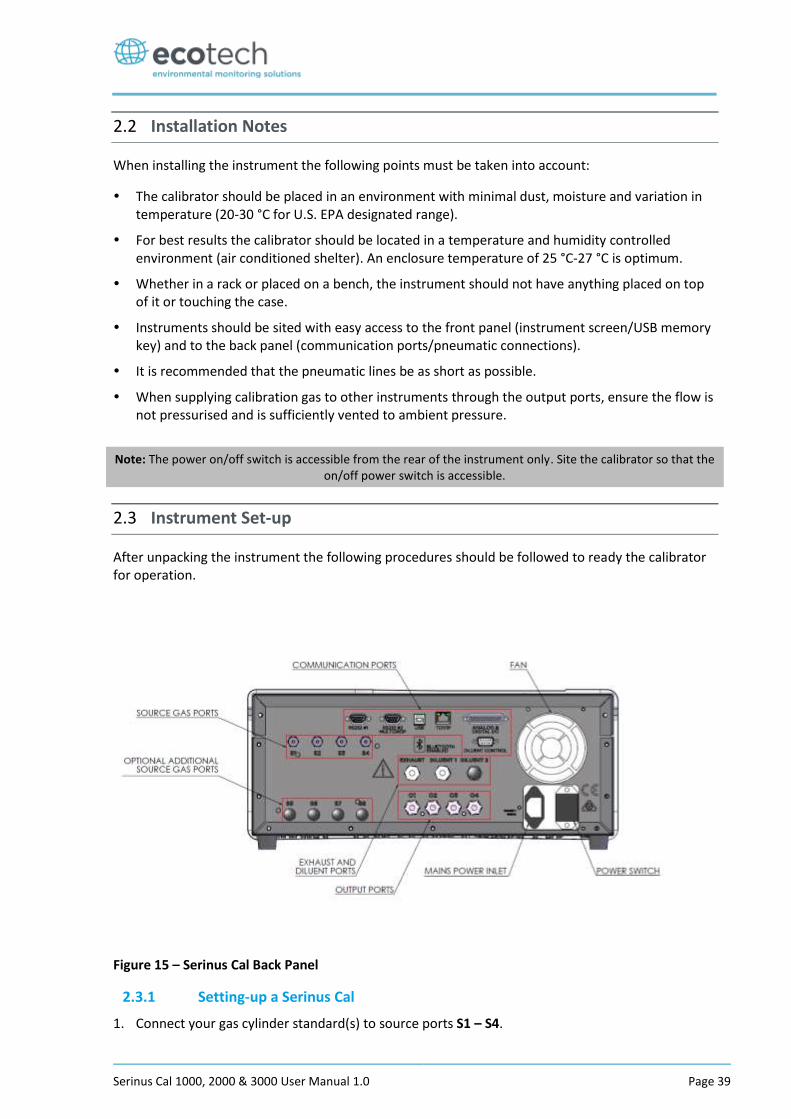
Serinus Cal 1000, 2000 & 3000 User Manual 1.0 Page 39
2.2 Installation Notes
When installing the instrument the following points must be taken into account:
The calibrator should be placed in an environment with minimal dust, moisture and variation in temperature (20-30 °C for U.S. EPA designated range).
For best results the calibrator should be located in a temperature and humidity controlled environment (air conditioned shelter). An enclosure temperature of 25 °C-27 °C is optimum.
Whether in a rack or placed on a bench, the instrument should not have anything placed on top of it or touching the case.
Instruments should be sited with easy access to the front panel (instrument screen/USB memory key) and to the back panel (communication ports/pneumatic connections).
It is recommended that the pneumatic lines be as short as possible.
When supplying calibration gas to other instruments through the output ports, ensure the flow is not pressurised and is sufficiently vented to ambient pressure.
Note: The power on/off switch is accessible from the rear of the instrument only. Site the calibrator so that the on/off power switch is accessible.
2.3 Instrument Set-up
After unpacking the instrument the following procedures should be followed to ready the calibrator for operation.
Figure 15 – Serinus Cal Back Panel
2.3.1 Setting-up a Serinus Cal
1. Connect your gas cylinder standard(s) to source ports S1 – S4.
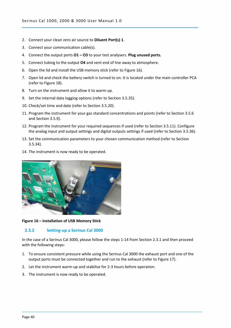
Serinus Cal 1000, 2000 & 3000 User Manual 1.0
Page 40
2. Connect your clean zero air source to Diluent Port(s) 1.
3. Connect your communication cable(s).
4. Connect the output ports O1 – O3 to your test analysers. Plug unused ports.
5. Connect tubing to the output O4 and vent end of line away to atmosphere.
6. Open the lid and install the USB memory stick (refer to Figure 16).
7. Open lid and check the battery switch is turned to on. It is located under the main controller PCA (refer to Figure 18).
8. Turn on the instrument and allow it to warm-up.
9. Set the internal data logging options (refer to Section 3.5.35).
10. Check/set time and date (refer to Section 3.5.20).
11. Program the instrument for your gas standard concentrations and points (refer to Section 3.5.6 and Section 3.5.9).
12. Program the instrument for your required sequences if used (refer to Section 3.5.11). Configure the analog input and output settings and digital outputs settings if used (refer to Section 3.5.36).
13. Set the communication parameters to your chosen communication method (refer to Section 3.5.34).
14. The instrument is now ready to be operated.
Figure 16 – Installation of USB Memory Stick
2.3.2 Setting-up a Serinus Cal 3000
In the case of a Serinus Cal 3000, please follow the steps 1-14 from Section 2.3.1 and then proceed with the following steps:
1. To ensure consistent pressure while using the Serinus Cal 3000 the exhaust port and one of the output ports must be connected together and run to the exhaust (refer to Figure 17).
2. Let the instrument warm-up and stabilise for 2-3 hours before operation.
3. The instrument is now ready to be operated.
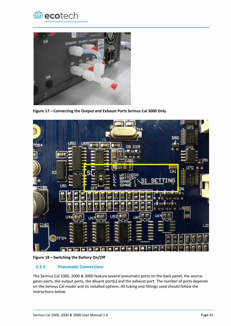
Serinus Cal 1000, 2000 & 3000 User Manual 1.0 Page 41
Figure 17 – Connecting the Output and Exhaust Ports Serinus Cal 3000 Only
Figure 18 – Switching the Battery On/Off
2.3.3 Pneumatic Connections
The Serinus Cal 1000, 2000 & 3000 feature several pneumatic ports on the back panel; the source gases ports, the output ports, the diluent port(s) and the exhaust port. The number of ports depends on the Serinus Cal model and its installed options. All tubing and fittings used should follow the instructions below:
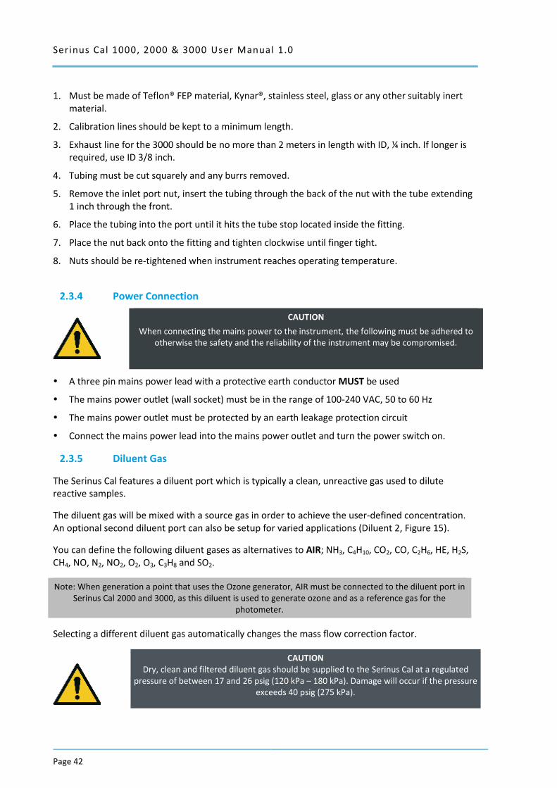
Serinus Cal 1000, 2000 & 3000 User Manual 1.0
Page 42
1. Must be made of Teflon® FEP material, Kynar®, stainless steel, glass or any other suitably inert material.
2. Calibration lines should be kept to a minimum length.
3. Exhaust line for the 3000 should be no more than 2 meters in length with ID, ¼ inch. If longer is required, use ID 3/8 inch.
4. Tubing must be cut squarely and any burrs removed.
5. Remove the inlet port nut, insert the tubing through the back of the nut with the tube extending 1 inch through the front.
6. Place the tubing into the port until it hits the tube stop located inside the fitting.
7. Place the nut back onto the fitting and tighten clockwise until finger tight.
8. Nuts should be re-tightened when instrument reaches operating temperature.
2.3.4 Power Connection
CAUTION
When connecting the mains power to the instrument, the following must be adhered to otherwise the safety and the reliability of the instrument may be compromised.
A three pin mains power lead with a protective earth conductor MUST be used
The mains power outlet (wall socket) must be in the range of 100-240 VAC, 50 to 60 Hz
The mains power outlet must be protected by an earth leakage protection circuit
Connect the mains power lead into the mains power outlet and turn the power switch on.
2.3.5 Diluent Gas
The Serinus Cal features a diluent port which is typically a clean, unreactive gas used to dilute reactive samples.
The diluent gas will be mixed with a source gas in order to achieve the user-defined concentration. An optional second diluent port can also be setup for varied applications (Diluent 2, Figure 15).
You can define the following diluent gases as alternatives to AIR; NH3, C4H10, CO2, CO, C2H6, HE, H2S, CH4, NO, N2, NO2, O2, O3, C3H8 and SO2.
Note: When generation a point that uses the Ozone generator, AIR must be connected to the diluent port in Serinus Cal 2000 and 3000, as this diluent is used to generate ozone and as a reference gas for the
photometer.
Selecting a different diluent gas automatically changes the mass flow correction factor.
CAUTION Dry, clean and filtered diluent gas should be supplied to the Serinus Cal at a regulated
pressure of between 17 and 26 psig (120 kPa – 180 kPa). Damage will occur if the pressure exceeds 40 psig (275 kPa).
Serinus Cal 1000, 2000 & 3000 User Manual 1.0 Page 43
2.3.6 Source Gas
The gas standards connect via the source gas port(s), labelled S1 to S4 (refer to Figure 15). Dry, clean and filtered source gas should be supplied to the Serinus Cal at a regulated pressure of between 100 – 300 kPa.
1/8” stainless steel tubing should be used with the supplied fittings. Only ¾ of a turn is required after finger tightening the nut. Serious damage may result from over-tightening.
An optional second inlet manifold can also be added in order to increase the number of source gases to 8 (ports S5-S8, refer to Figure 15)
WARNING Do not supply flammable gas mixtures to the Serinus Cal. The MFC’s use an internal
heated element which has the potential to cause an explosion. Particular attention should be paid to Hydrogen, Oxygen and Methane source gases.
2.3.7 Output Ports
There are four output gas ports available on the Serinus Cal, labelled O1 to O4. Diluted source gas is sent to each of the four output ports. Chemically inert Kynar fittings have been used and should be finger tight only. If any of the output ports are not used, they should be sealed with the supplied Kynar nut. One of the output ports must be connected to vent in order to avoid pressurising the unit. Damage to the equipment may occur if the output pneumatic system is pressurised.
CAUTION
One of the output ports must be connected to the vent in order to avoid pressuring the unit.
2.3.8 Exhaust Port
The exhaust port is where the output of the purge valve is connected as well as the output of the ozone generator when it is not in use. In the case of the Serinus Cal 3000, the exhaust of the internal photometer pump is connected to this port (refer to Figure 17). The exhaust port must be connected to an exhaust manifold venting to a suitable location outside the room and away from the sample inlets of gas analysers in the system.
2.3.9 Purge for Gas Lines
The calibrator includes a purge option that allows venting of gases without the danger of contaminating other gas standards. Default setting is OFF but with this firmware option enabled, gases are purged for a set period of time out the exhaust port or whenever a source gas is changed (user defined).
If the optional second source MFC is installed, one of the source ports (S4) is used as the purge port. In this situation the source port (S4) should be externally connected to the exhaust port.
CAUTION
It is recommended that exhaust air is not expelled into a shelter/room inhabited by people. It should be expelled into the external air and away from the
sample inlet of gas analysers.
Serinus Cal 1000, 2000 & 3000 User Manual 1.0
Page 44
2.3.10 Communications Connections
There are a number of ways to communicate with the instrument. The user can use the supplied Airodis software to access the instrument and download data. The Airodis software is supplied on the green resources USB stick provided with this instrument. Other software such as WinAQMS can also be used to control and setup the instrument.
RS232 #1
Connect this port to a data logger (such as WinAQMS) with an RS232 cable.
RS232 #2
Connect the RS232 cable from the instrument to a computer, data logger or in a multidrop formation.
Note: When using multidrop ensure each instrument is given a unique instrument ID.
USB
Connect a standard type B USB cable (supplied with the instrument) to this port.
TCP/IP (optional)
Plug in an ethernet cable (this cable should be attached to a network).
Analog/Digital
This port is used to send and receive analog and digital signals between instruments. It is normally used to connect with a gas analyser or data logger to activate calibration points and sequences.
Each instrument contains 8 digital inputs, 8 digital outputs, 3 analog inputs and 1 analog output.
Diluent Control
This port is used to control an external Zero Air Generator (such as the Ecotech 8301LC) by providing a 12V signal when the Diluent is required.
Bluetooth
Connection is enabled using Ecotech’s Serinus remote Android application.
Use the Serinus remote Android application to access instrument and download data. It is available for download directly from the Google Play Store. Search for ‘Ecotech Serinus Remote’.
2.4 Transporting/Storage
Transporting the Serinus Cal should be done with great care. It is recommended that the packaging the Serinus Cal was delivered in should be used when transporting or storing the instrument.
When transporting or storing the instrument the following points should be followed:
1. Turn off the instrument and allow it to cool down.

Serinus Cal 1000, 2000 & 3000 User Manual 1.0 Page 45
2. Remove all pneumatic, power and communication connections.
3. If storing over a long period (6 months) turn the battery off by switching the switch (S1) on the main controller PCA to off (refer to Figure 18).
4. Remove the instrument from the rack.
5. Replace the red plugs into the pneumatic connections.
6. Remove the USB memory stick and pack with instrument (refer to Figure 16)
7. Place the instrument back into a plastic bag with desiccant packs and seal the bag (ideally the bag it was delivered in).
8. Place the instrument back into the original foam and box it was delivered in. If this is no longer available find some equivalent packaging which provides protection from damage.
9. The instrument is now ready for long term storage or transportation.

Serinus Cal 1000, 2000 & 3000 User Manual 1.0
Page 46
This page is intentionally blank
Serinus Cal 1000, 2000 & 3000 User Manual 1.0 Page 47
3 Operation
3.1 Warm-Up
No warm up period is required for Serinus Cal 1000 or 2000, both calibrators are ready to begin operation immediately. It is suggested you allow the instrument to warm up for one hour, allowing the instrument to stabilise to the surrounding environment for best results.
The photometer portion of the Serinus Cal 3000 requires a warm up period before it can execute a photometer point. During this period, the instrument will adjust itself to prepare for monitoring. Other functions are available immediately at start up.
The following activities occur during Serinus Cal 3000 warm-up:
Lamp Adjust
The instrument automatically adjusts the lamp’s current (10mA) for a stable (reference voltage) signal/output (2 minutes).
Ref Stabilise
The instrument sets the reference voltage to 2.8 - 3.2V output and waits for a stable output signal.
Zero Adjust
The instrument sets the course and fines zero pots for a zero detector output.
Zero Stabilise
The instrument waits until the zero voltage signals are stable.
After this warm-up has completed the Serinus Cal 3000 can execute photometer points.
3.2 Theory of Operation
The Serinus Cal operates by using diluent gas definition, gas standard definitions, points and sequences.
When setting up the Serinus Cal for the first time you will need to first define you gas standards that you will be connecting to the instrument via the source ports and the diluent gas via the diluent port. This needs to be done before any points or sequences can be defined.
There are 4 source ports (standard) but you can define up to 10 gas standards definitions within the instrument.
There is 1 diluent port (standard) this should be configured to match the gas connected to the diluent port.
From the gas standard definitions points can be defined. A point is a user-defined configuration of gas flows. Up to 32 points can be defined and named. Each point can perform a different operation (gas dilution, zero point, source control etc.), utilizing different diluent gas, gas standards, flows, and concentrations.
Serinus Cal 1000, 2000 & 3000 User Manual 1.0
Page 48
A sequence is a series of points. Up to 16 sequences can be defined. Each sequence can run up to 16 points for a user-specified amount of time. Sequences can also run other sequences as one of their actions, allowing for very complex series of points to be executed. The nesting of sequences can only go three deep before you will get a nesting error. To signify the end of a sequence you can select the repeat or idle action, which will repeat the sequence or place the Serinus Cal into Idle.
Points or sequences can be initiated from the home screen (the Mode button), or they can be initiated remotely via digital inputs or serial commands.
For convenience there is a ‘Manual’ point. This is exactly like a point definition except it does not occupy one of the 32 named point definitions. It is useful for operating the machine in an immediate mode where flow and concentration changes can be done on the fly. Points created in manual mode can be copied to a point number and given a name when the user wants to keep it long term and is satisfied.
3.2.1 Running a Point or Sequence
Initially the Serinus Cal requires several steps to be followed in order to run an automatic point or sequence.
Program your gas cylinder concentrations and diluent gas in the Gas Supply Menu
Program points in the Points & Sequencing Menu
Program sequences (if applicable) in the Points & Sequencing Menu
Start the desired point or sequence by accessing the Quick Menu Mode and selecting point or sequence.
3.2.2 Operation
When defining a point you first need to select an operation. Each of the variants has a different number of operations available to the user. The Serinus Cal 1000 has three operations, Gas Dilution, Zero Point and Source Control. The Serinus Cal 2000 has five operations, Gas Dilution, Zero Point, Source Control, Titration and O3 Generator. The Serinus Cal has six operations, Gas Dilution, Zero Point, Source Control, Titration, O3 Generator and O3 Gen/Photometer. The following sections give examples of each type of operation and how set them up.
3.2.2.1 Gas Dilution
Step by Step Example:
1. Open - Main Menu Gas Supply Menu Edit Gas Standards Menu.
2. Edit - Standard 1.
Note: Not all fields within the Edit gas standard menu are mandatory. Such as serial number and expiration date. Serial No. and Expiration are information fields for your gas cylinder. Balance Gas is typically N2 and will
be stated on your gas cylinder certificate.
3. Refer to your gas cylinder certificate and input gas types, concentrations and units for each gas component within the cylinder.
4. Edit - Serial No. - (as stated on the certificate).
5. Edit - Expiration - (as stated on the certificate).
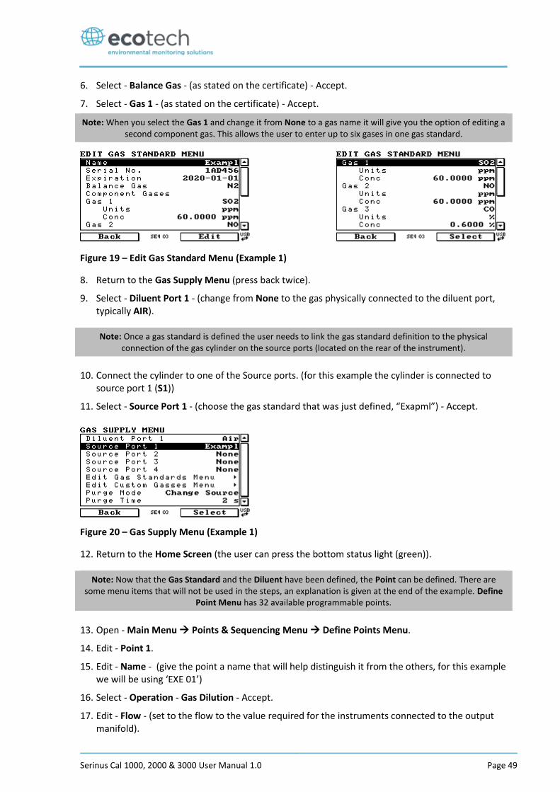
Serinus Cal 1000, 2000 & 3000 User Manual 1.0 Page 49
6. Select - Balance Gas - (as stated on the certificate) - Accept.
7. Select - Gas 1 - (as stated on the certificate) - Accept.
Note: When you select the Gas 1 and change it from None to a gas name it will give you the option of editing a second component gas. This allows the user to enter up to six gases in one gas standard.
Figure 19 – Edit Gas Standard Menu (Example 1)
8. Return to the Gas Supply Menu (press back twice).
9. Select - Diluent Port 1 - (change from None to the gas physically connected to the diluent port, typically AIR).
Note: Once a gas standard is defined the user needs to link the gas standard definition to the physical connection of the gas cylinder on the source ports (located on the rear of the instrument).
10. Connect the cylinder to one of the Source ports. (for this example the cylinder is connected to source port 1 (S1))
11. Select - Source Port 1 - (choose the gas standard that was just defined, “Exapml”) - Accept.
Figure 20 – Gas Supply Menu (Example 1)
12. Return to the Home Screen (the user can press the bottom status light (green)).
Note: Now that the Gas Standard and the Diluent have been defined, the Point can be defined. There are some menu items that will not be used in the steps, an explanation is given at the end of the example. Define
Point Menu has 32 available programmable points.
13. Open - Main Menu Points & Sequencing Menu Define Points Menu.
14. Edit - Point 1.
15. Edit - Name - (give the point a name that will help distinguish it from the others, for this example we will be using ‘EXE 01’)
16. Select - Operation - Gas Dilution - Accept.
17. Edit - Flow - (set to the flow to the value required for the instruments connected to the output manifold).
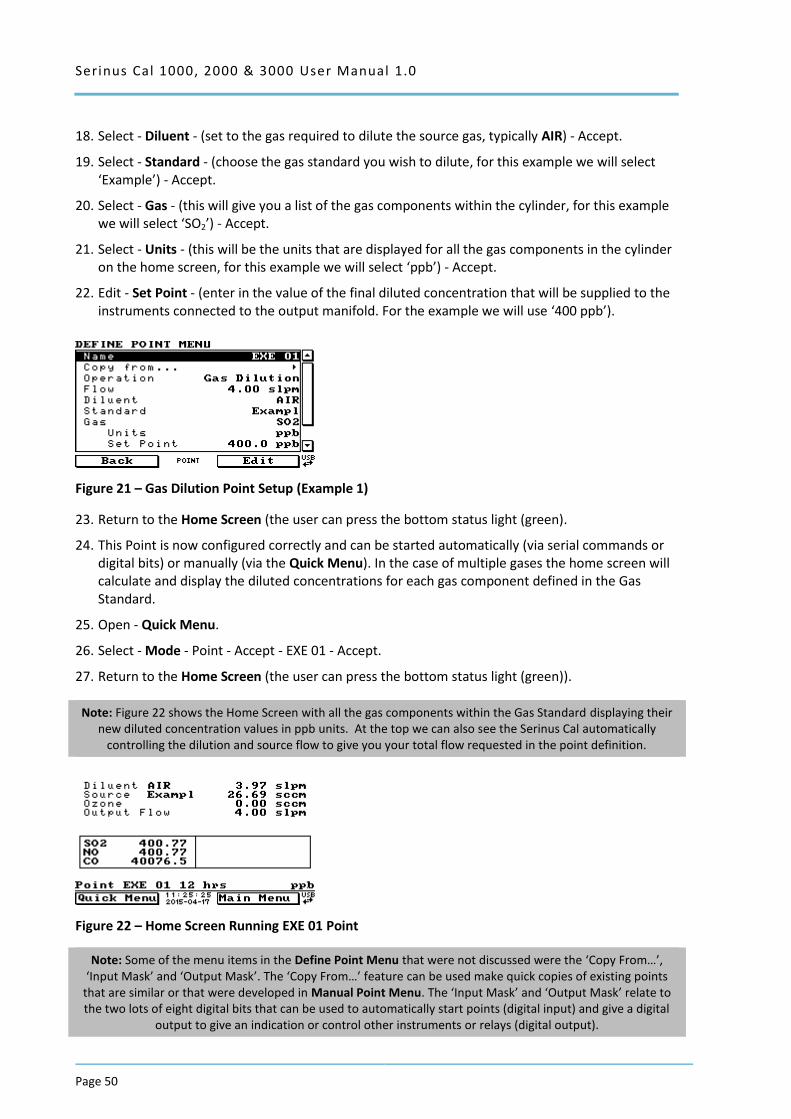
Serinus Cal 1000, 2000 & 3000 User Manual 1.0
Page 50
18. Select - Diluent - (set to the gas required to dilute the source gas, typically AIR) - Accept.
19. Select - Standard - (choose the gas standard you wish to dilute, for this example we will select ‘Example’) - Accept.
20. Select - Gas - (this will give you a list of the gas components within the cylinder, for this example we will select ‘SO2’) - Accept.
21. Select - Units - (this will be the units that are displayed for all the gas components in the cylinder on the home screen, for this example we will select ‘ppb’) - Accept.
22. Edit - Set Point - (enter in the value of the final diluted concentration that will be supplied to the instruments connected to the output manifold. For the example we will use ‘400 ppb’).
Figure 21 – Gas Dilution Point Setup (Example 1)
23. Return to the Home Screen (the user can press the bottom status light (green).
24. This Point is now configured correctly and can be started automatically (via serial commands or digital bits) or manually (via the Quick Menu). In the case of multiple gases the home screen will calculate and display the diluted concentrations for each gas component defined in the Gas Standard.
25. Open - Quick Menu.
26. Select - Mode - Point - Accept - EXE 01 - Accept.
27. Return to the Home Screen (the user can press the bottom status light (green)).
Note: Figure 22 shows the Home Screen with all the gas components within the Gas Standard displaying their new diluted concentration values in ppb units. At the top we can also see the Serinus Cal automatically
controlling the dilution and source flow to give you your total flow requested in the point definition.
Figure 22 – Home Screen Running EXE 01 Point
Note: Some of the menu items in the Define Point Menu that were not discussed were the ‘Copy From…’, ‘Input Mask’ and ‘Output Mask’. The ‘Copy From…’ feature can be used make quick copies of existing points
that are similar or that were developed in Manual Point Menu. The ‘Input Mask’ and ‘Output Mask’ relate to the two lots of eight digital bits that can be used to automatically start points (digital input) and give a digital
output to give an indication or control other instruments or relays (digital output).

Serinus Cal 1000, 2000 & 3000 User Manual 1.0 Page 51
3.2.2.2 Zero Point
Step by Step Example:
1. Open - Main Menu Gas Supply Menu
2. Select - Diluent Port 1 - (change from None to the gas physically connected to the diluent port, typically AIR).
3. Return to the Home Screen (the user can press the bottom status light (green)).
Note: Now that the Diluent has been defined, the Point can be defined. There are some menu items that will not be used in the steps, an explanation is given at the end of the example. Define Point Menu has 32 available
programmable points.
4. Open - Main Menu Points & Sequences Menu Define Points Menu.
5. Edit - Point 2.
6. Edit - Name - (give the point a name that will help distinguish it from the others, for this example we will be using ‘EXE 02’)
7. Select - Operation – Zero Point - Accept (the flow will default to the lowest flow possible, typically 0.50 slpm).
8. Edit - Flow - (set to the flow to the value required for the instruments connected to the output manifold, for this example we will set it to 5.0 slpm).
9. Select - Diluent - (change to gas required for zero point, typically AIR) - Accept.
Figure 23 – Zero Point Setup
10. Return to the Home Screen (the user can press the bottom status light (green)).
11. This Point is now configured correctly and can be started automatically (via serial commands or digital bits) or manually (via the Quick Menu).
12. Open - Quick Menu.
13. Select - Mode - Point - Accept - EXE 02 - Accept.
Note: Figure 24 shows the Home Screen with the Serinus Cal automatically controlling the dilution flow to give you your total flow requested in the point definition.
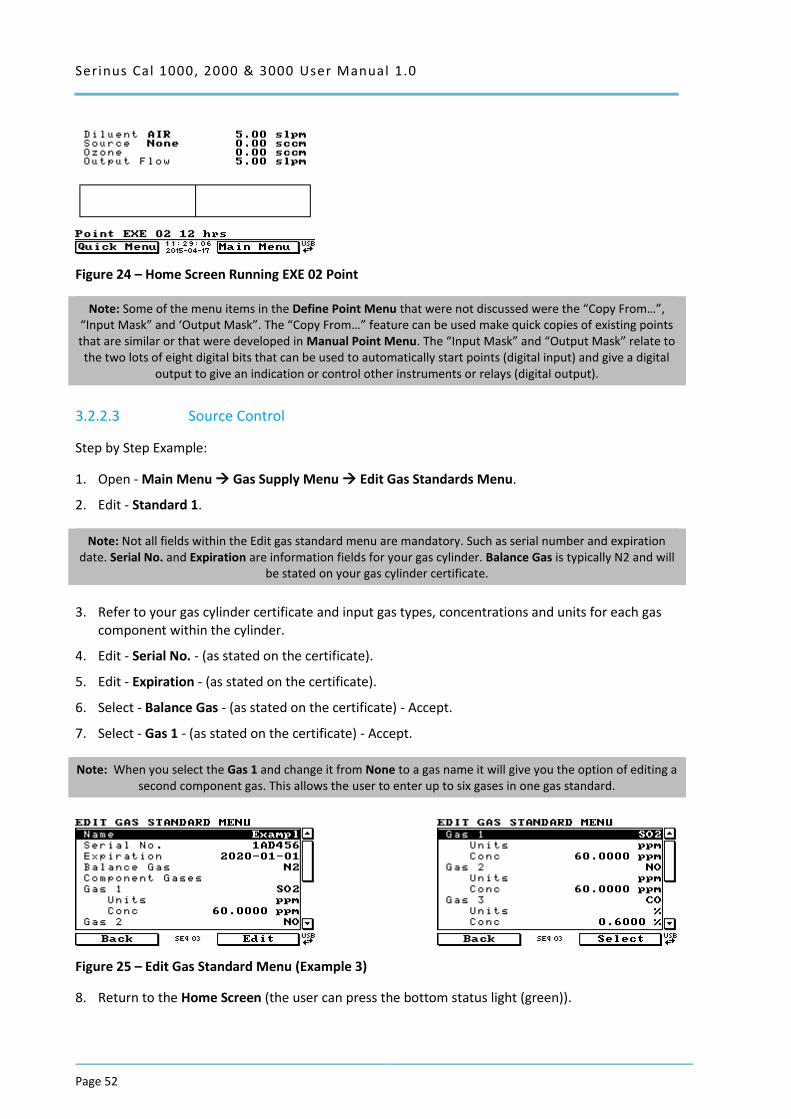
Serinus Cal 1000, 2000 & 3000 User Manual 1.0
Page 52
Figure 24 – Home Screen Running EXE 02 Point
Note: Some of the menu items in the Define Point Menu that were not discussed were the “Copy From…”, “Input Mask” and ‘Output Mask”. The “Copy From…” feature can be used make quick copies of existing points that are similar or that were developed in Manual Point Menu. The “Input Mask” and “Output Mask” relate to the two lots of eight digital bits that can be used to automatically start points (digital input) and give a digital
output to give an indication or control other instruments or relays (digital output).
3.2.2.3 Source Control
Step by Step Example:
1. Open - Main Menu Gas Supply Menu Edit Gas Standards Menu.
2. Edit - Standard 1.
Note: Not all fields within the Edit gas standard menu are mandatory. Such as serial number and expiration date. Serial No. and Expiration are information fields for your gas cylinder. Balance Gas is typically N2 and will
be stated on your gas cylinder certificate.
3. Refer to your gas cylinder certificate and input gas types, concentrations and units for each gas component within the cylinder.
4. Edit - Serial No. - (as stated on the certificate).
5. Edit - Expiration - (as stated on the certificate).
6. Select - Balance Gas - (as stated on the certificate) - Accept.
7. Select - Gas 1 - (as stated on the certificate) - Accept.
Note: When you select the Gas 1 and change it from None to a gas name it will give you the option of editing a second component gas. This allows the user to enter up to six gases in one gas standard.
Figure 25 – Edit Gas Standard Menu (Example 3)
8. Return to the Home Screen (the user can press the bottom status light (green)).
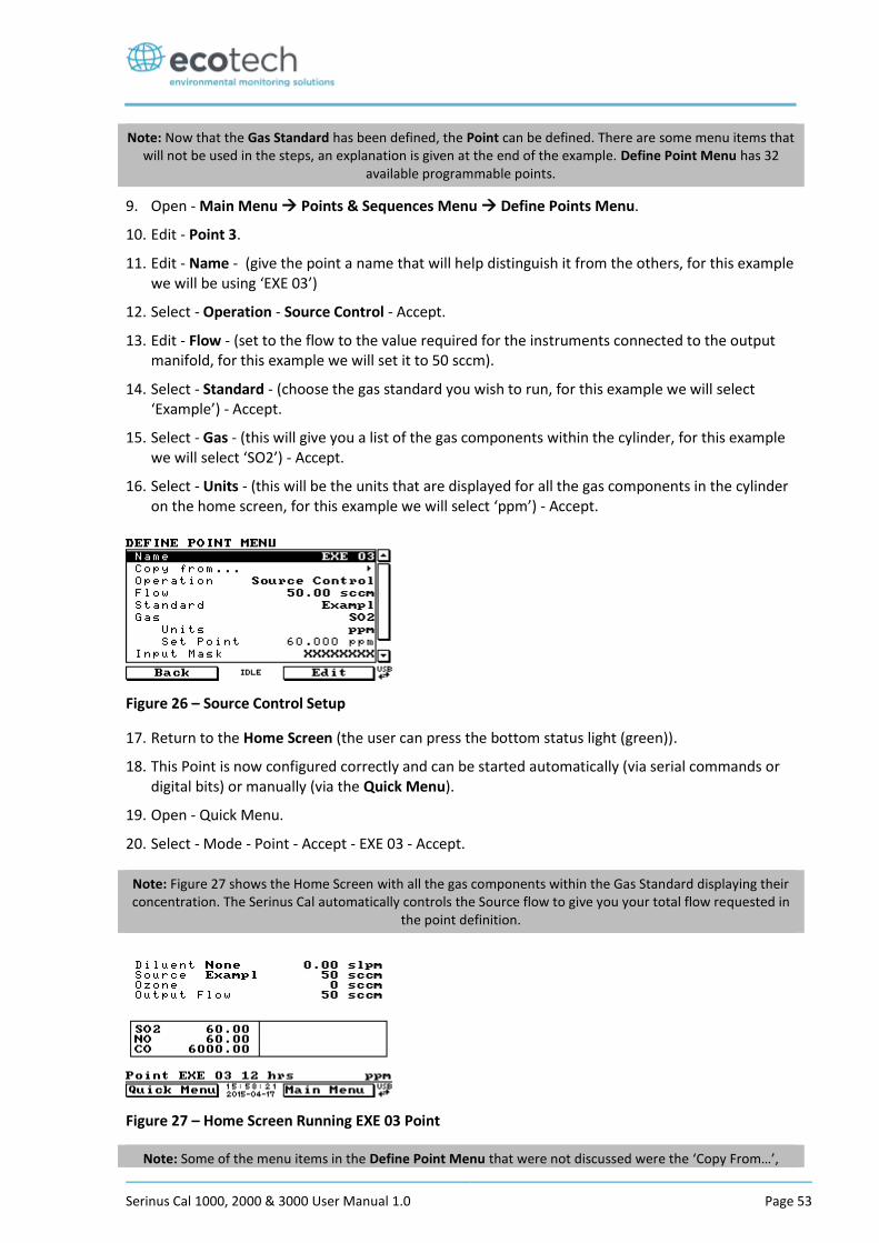
Serinus Cal 1000, 2000 & 3000 User Manual 1.0 Page 53
Note: Now that the Gas Standard has been defined, the Point can be defined. There are some menu items that will not be used in the steps, an explanation is given at the end of the example. Define Point Menu has 32
available programmable points.
9. Open - Main Menu Points & Sequences Menu Define Points Menu.
10. Edit - Point 3.
11. Edit - Name - (give the point a name that will help distinguish it from the others, for this example we will be using ‘EXE 03’)
12. Select - Operation - Source Control - Accept.
13. Edit - Flow - (set to the flow to the value required for the instruments connected to the output manifold, for this example we will set it to 50 sccm).
14. Select - Standard - (choose the gas standard you wish to run, for this example we will select ‘Example’) - Accept.
15. Select - Gas - (this will give you a list of the gas components within the cylinder, for this example we will select ‘SO2’) - Accept.
16. Select - Units - (this will be the units that are displayed for all the gas components in the cylinder on the home screen, for this example we will select ‘ppm’) - Accept.
Figure 26 – Source Control Setup
17. Return to the Home Screen (the user can press the bottom status light (green)).
18. This Point is now configured correctly and can be started automatically (via serial commands or digital bits) or manually (via the Quick Menu).
19. Open - Quick Menu.
20. Select - Mode - Point - Accept - EXE 03 - Accept.
Note: Figure 27 shows the Home Screen with all the gas components within the Gas Standard displaying their concentration. The Serinus Cal automatically controls the Source flow to give you your total flow requested in
the point definition.
Figure 27 – Home Screen Running EXE 03 Point
Note: Some of the menu items in the Define Point Menu that were not discussed were the ‘Copy From…’,

Serinus Cal 1000, 2000 & 3000 User Manual 1.0
Page 54
‘Input Mask’ and ‘Output Mask’. The ‘Copy From…’ feature can be used make quick copies of existing points that are similar or that were developed in Manual Point Menu. The ‘Input Mask’ and ‘Output Mask’ relate to the two lots of eight digital bits that can be used to automatically start points (digital input) and give a digital
output to give an indication or control other instruments or relays (digital output).
3.2.2.4 Titration (Serinus Cal 2000, 3000)
Step by Step Example:
1. Open - Main Menu Gas Supply Menu Edit Gas Standards Menu.
2. Edit - Standard 1.
Note: Not all fields within the Edit gas standard menu are mandatory. Such as serial number and expiration date. Serial No. and Expiration are information fields for your gas cylinder. Balance Gas is typically N2 and will
be stated on your gas cylinder certificate.
3. Refer to your gas cylinder certificate and input gas types, concentrations and units for each gas component within the cylinder.
4. Edit - Serial No. - (as stated on the certificate).
5. Edit - Expiration - (as stated on the certificate).
6. Select - Balance Gas - (as stated on the certificate) - Accept.
7. Select - Gas 1 - (as stated on the certificate) - Accept.
Note: When you select the Gas 1 and change it from None to a gas name it will give you the option of editing a second component gas. This allows the user to enter up to six gases in one gas standard.
Figure 28 – Edit Gas Standard Menu (Example 4)
8. Return to the Gas Supply Menu (press back twice).
9. Select - Diluent Port 1 - (change from None to the gas physically connected to the diluent port, typically AIR. When using the Titration operation you must select a diluent that contains sufficient oxygen so the Ozone generator can produce Ozone).
Note: Once a gas standard is defined the user needs to link the gas standard definition to the physical connection of the gas cylinder on the source ports (located on the rear of the instrument).
10. Connect the cylinder to one of the Source ports. (for this example the cylinder is connected to source port 1 (S1))
11. Select - Source Port 1 - (choose the gas standard that was just defined, “Exapml”) - Accept.
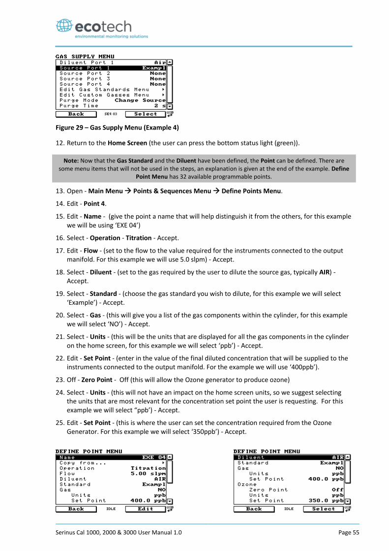
Serinus Cal 1000, 2000 & 3000 User Manual 1.0 Page 55
Figure 29 – Gas Supply Menu (Example 4)
12. Return to the Home Screen (the user can press the bottom status light (green)).
Note: Now that the Gas Standard and the Diluent have been defined, the Point can be defined. There are some menu items that will not be used in the steps, an explanation is given at the end of the example. Define
Point Menu has 32 available programmable points.
13. Open - Main Menu Points & Sequences Menu Define Points Menu.
14. Edit - Point 4.
15. Edit - Name - (give the point a name that will help distinguish it from the others, for this example we will be using ‘EXE 04’)
16. Select - Operation - Titration - Accept.
17. Edit - Flow - (set to the flow to the value required for the instruments connected to the output manifold. For this example we will use 5.0 slpm) - Accept.
18. Select - Diluent - (set to the gas required by the user to dilute the source gas, typically AIR) - Accept.
19. Select - Standard - (choose the gas standard you wish to dilute, for this example we will select ‘Example’) - Accept.
20. Select - Gas - (this will give you a list of the gas components within the cylinder, for this example we will select ‘NO’) - Accept.
21. Select - Units - (this will be the units that are displayed for all the gas components in the cylinder on the home screen, for this example we will select ‘ppb’) - Accept.
22. Edit - Set Point - (enter in the value of the final diluted concentration that will be supplied to the instruments connected to the output manifold. For the example we will use ‘400ppb’).
23. Off - Zero Point - Off (this will allow the Ozone generator to produce ozone)
24. Select - Units - (this will not have an impact on the home screen units, so we suggest selecting the units that are most relevant for the concentration set point the user is requesting. For this example we will select “ppb’) - Accept.
25. Edit - Set Point - (this is where the user can set the concentration required from the Ozone Generator. For this example we will select ‘350ppb’) - Accept.
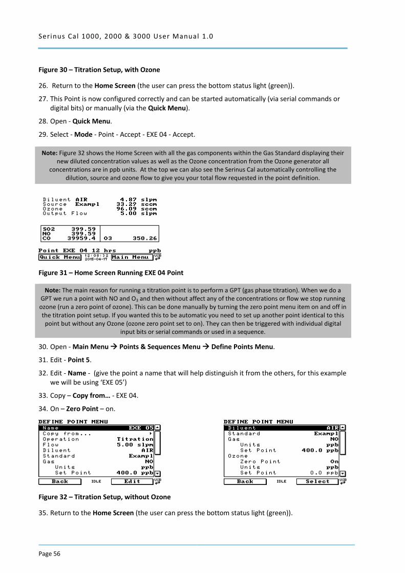
Serinus Cal 1000, 2000 & 3000 User Manual 1.0
Page 56
Figure 30 – Titration Setup, with Ozone
26. Return to the Home Screen (the user can press the bottom status light (green)).
27. This Point is now configured correctly and can be started automatically (via serial commands or digital bits) or manually (via the Quick Menu).
28. Open - Quick Menu.
29. Select - Mode - Point - Accept - EXE 04 - Accept.
Note: Figure 32 shows the Home Screen with all the gas components within the Gas Standard displaying their new diluted concentration values as well as the Ozone concentration from the Ozone generator all
concentrations are in ppb units. At the top we can also see the Serinus Cal automatically controlling the dilution, source and ozone flow to give you your total flow requested in the point definition.
Figure 31 – Home Screen Running EXE 04 Point
Note: The main reason for running a titration point is to perform a GPT (gas phase titration). When we do a GPT we run a point with NO and O3 and then without affect any of the concentrations or flow we stop running ozone (run a zero point of ozone). This can be done manually by turning the zero point menu item on and off in the titration point setup. If you wanted this to be automatic you need to set up another point identical to this
point but without any Ozone (ozone zero point set to on). They can then be triggered with individual digital input bits or serial commands or used in a sequence.
30. Open - Main Menu Points & Sequences Menu Define Points Menu.
31. Edit - Point 5.
32. Edit - Name - (give the point a name that will help distinguish it from the others, for this example we will be using ‘EXE 05’)
33. Copy – Copy from… - EXE 04.
34. On – Zero Point – on.
Figure 32 – Titration Setup, without Ozone
35. Return to the Home Screen (the user can press the bottom status light (green)).
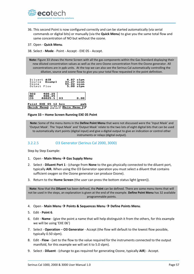
Serinus Cal 1000, 2000 & 3000 User Manual 1.0 Page 57
36. This second Point is now configured correctly and can be started automatically (via serial commands or digital bits) or manually (via the Quick Menu) to give you the same total flow and same concentration of NO but without the ozone.
37. Open - Quick Menu.
38. Select - Mode - Point - Accept - EXE 05 - Accept.
Note: Figure 33 shows the Home Screen with all the gas components within the Gas Standard displaying their new diluted concentration values as well as the zero Ozone concentration from the Ozone generator. All concentrations are in ppb units. At the top we can also see the Serinus Cal automatically controlling the
dilution, source and ozone flow to give you your total flow requested in the point definition.
Figure 33 – Home Screen Running EXE 05 Point
Note: Some of the menu items in the Define Point Menu that were not discussed were the ‘Input Mask’ and ‘Output Mask’. The ‘Input Mask’ and ‘Output Mask’ relate to the two lots of eight digital bits that can be used
to automatically start points (digital input) and give a digital output to give an indication or control other instruments or relays (digital output).
3.2.2.5 O3 Generator (Serinus Cal 2000, 3000)
Step by Step Example:
1. Open - Main Menu Gas Supply Menu
2. Select - Diluent Port 1 - (change from None to the gas physically connected to the diluent port, typically AIR. When using the O3 Generator operation you must select a diluent that contains sufficient oxygen so the Ozone generator can produce Ozone).
3. Return to the Home Screen (the user can press the bottom status light (green)).
Note: Now that the Diluent has been defined, the Point can be defined. There are some menu items that will not be used in the steps, an explanation is given at the end of the example. Define Point Menu has 32 available
programmable points.
4. Open - Main Menu Points & Sequences Menu Define Points Menu.
5. Edit - Point 6.
6. Edit - Name - (give the point a name that will help distinguish it from the others, for this example we will be using ‘EXE 06’)
7. Select - Operation – O3 Generator - Accept (the flow will default to the lowest flow possible, typically 0.50 slpm).
8. Edit - Flow - (set to the flow to the value required for the instruments connected to the output manifold, for this example we will set it to 5.0 slpm).
9. Select - Diluent - (change to gas required for generating Ozone, typically AIR) - Accept.
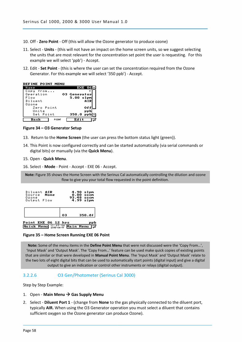
Serinus Cal 1000, 2000 & 3000 User Manual 1.0
Page 58
10. Off - Zero Point - Off (this will allow the Ozone generator to produce ozone)
11. Select - Units - (this will not have an impact on the home screen units, so we suggest selecting the units that are most relevant for the concentration set point the user is requesting. For this example we will select ‘ppb’) - Accept.
12. Edit - Set Point - (this is where the user can set the concentration required from the Ozone Generator. For this example we will select ‘350 ppb’) - Accept.
Figure 34 – O3 Generator Setup
13. Return to the Home Screen (the user can press the bottom status light (green)).
14. This Point is now configured correctly and can be started automatically (via serial commands or digital bits) or manually (via the Quick Menu).
15. Open - Quick Menu.
16. Select - Mode - Point - Accept - EXE 06 - Accept.
Note: Figure 35 shows the Home Screen with the Serinus Cal automatically controlling the dilution and ozone flow to give you your total flow requested in the point definition.
Figure 35 – Home Screen Running EXE 06 Point
Note: Some of the menu items in the Define Point Menu that were not discussed were the ‘Copy From…’, ‘Input Mask’ and ‘Output Mask’. The ‘Copy From…’ feature can be used make quick copies of existing points
that are similar or that were developed in Manual Point Menu. The ‘Input Mask’ and ‘Output Mask’ relate to the two lots of eight digital bits that can be used to automatically start points (digital input) and give a digital
output to give an indication or control other instruments or relays (digital output).
3.2.2.6 O3 Gen/Photometer (Serinus Cal 3000)
Step by Step Example:
1. Open - Main Menu Gas Supply Menu
2. Select - Diluent Port 1 - (change from None to the gas physically connected to the diluent port, typically AIR. When using the O3 Generator operation you must select a diluent that contains sufficient oxygen so the Ozone generator can produce Ozone).
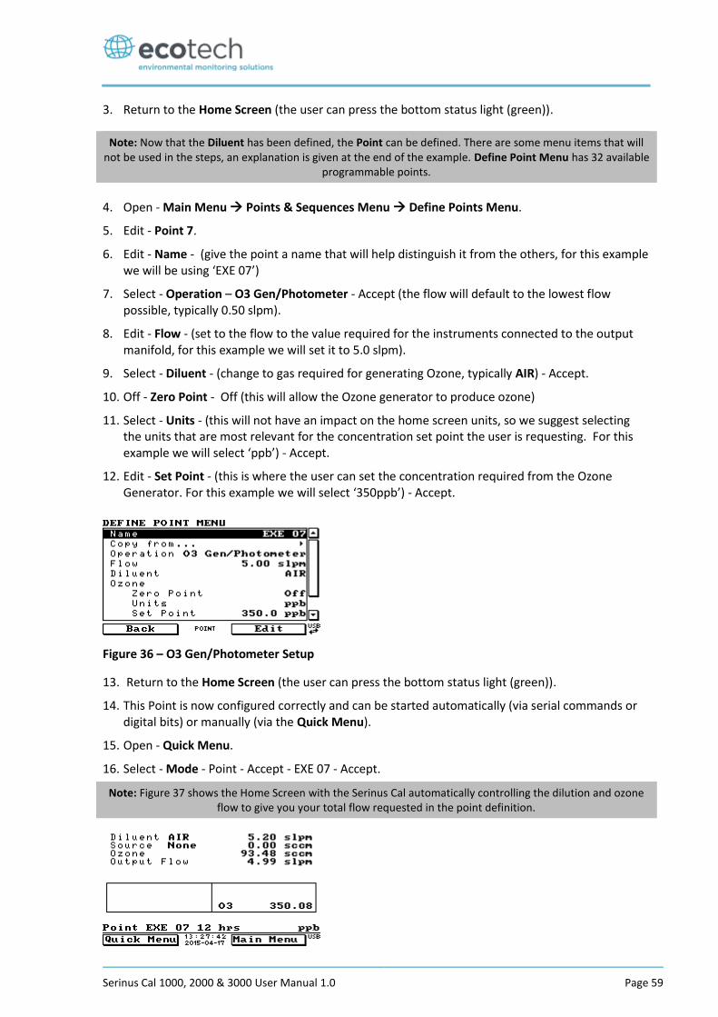
Serinus Cal 1000, 2000 & 3000 User Manual 1.0 Page 59
3. Return to the Home Screen (the user can press the bottom status light (green)).
Note: Now that the Diluent has been defined, the Point can be defined. There are some menu items that will not be used in the steps, an explanation is given at the end of the example. Define Point Menu has 32 available
programmable points.
4. Open - Main Menu Points & Sequences Menu Define Points Menu.
5. Edit - Point 7.
6. Edit - Name - (give the point a name that will help distinguish it from the others, for this example we will be using ‘EXE 07’)
7. Select - Operation – O3 Gen/Photometer - Accept (the flow will default to the lowest flow possible, typically 0.50 slpm).
8. Edit - Flow - (set to the flow to the value required for the instruments connected to the output manifold, for this example we will set it to 5.0 slpm).
9. Select - Diluent - (change to gas required for generating Ozone, typically AIR) - Accept.
10. Off - Zero Point - Off (this will allow the Ozone generator to produce ozone)
11. Select - Units - (this will not have an impact on the home screen units, so we suggest selecting the units that are most relevant for the concentration set point the user is requesting. For this example we will select ‘ppb’) - Accept.
12. Edit - Set Point - (this is where the user can set the concentration required from the Ozone Generator. For this example we will select ‘350ppb’) - Accept.
Figure 36 – O3 Gen/Photometer Setup
13. Return to the Home Screen (the user can press the bottom status light (green)).
14. This Point is now configured correctly and can be started automatically (via serial commands or digital bits) or manually (via the Quick Menu).
15. Open - Quick Menu.
16. Select - Mode - Point - Accept - EXE 07 - Accept.
Note: Figure 37 shows the Home Screen with the Serinus Cal automatically controlling the dilution and ozone flow to give you your total flow requested in the point definition.
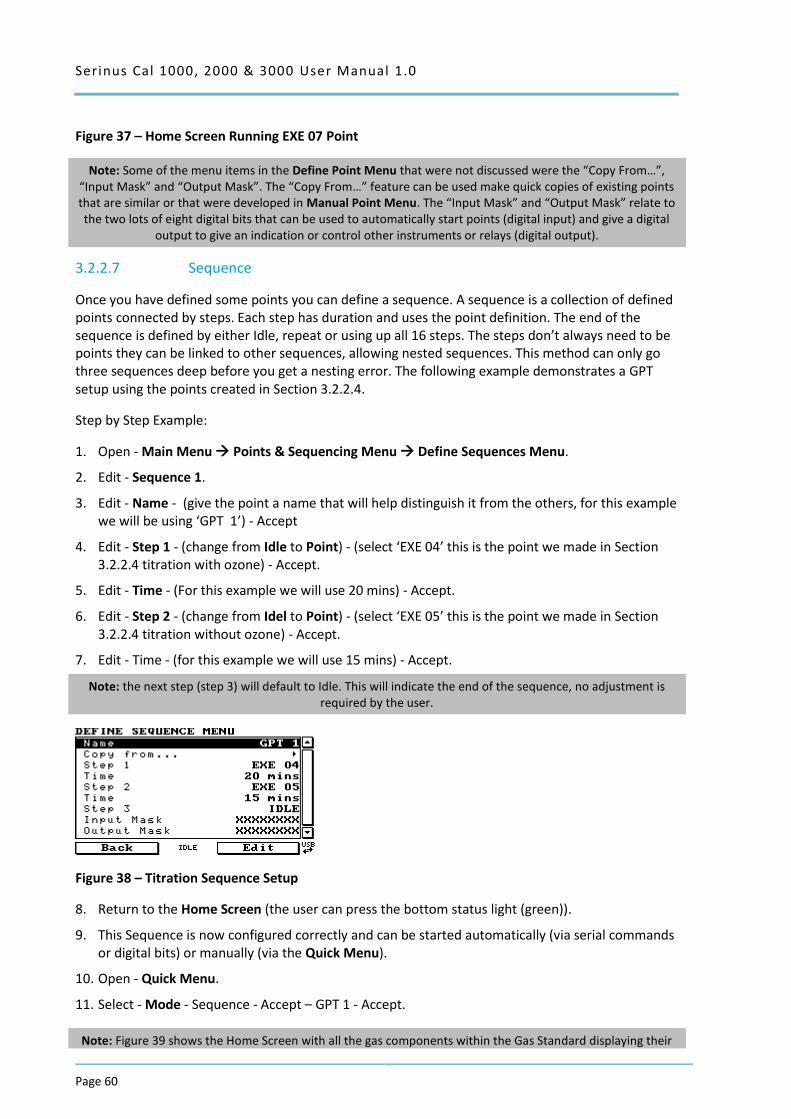
Serinus Cal 1000, 2000 & 3000 User Manual 1.0
Page 60
Figure 37 – Home Screen Running EXE 07 Point
Note: Some of the menu items in the Define Point Menu that were not discussed were the “Copy From…”, “Input Mask” and “Output Mask”. The “Copy From…” feature can be used make quick copies of existing points that are similar or that were developed in Manual Point Menu. The “Input Mask” and “Output Mask” relate to the two lots of eight digital bits that can be used to automatically start points (digital input) and give a digital
output to give an indication or control other instruments or relays (digital output).
3.2.2.7 Sequence
Once you have defined some points you can define a sequence. A sequence is a collection of defined points connected by steps. Each step has duration and uses the point definition. The end of the sequence is defined by either Idle, repeat or using up all 16 steps. The steps don’t always need to be points they can be linked to other sequences, allowing nested sequences. This method can only go three sequences deep before you get a nesting error. The following example demonstrates a GPT setup using the points created in Section 3.2.2.4.
Step by Step Example:
1. Open - Main Menu Points & Sequencing Menu Define Sequences Menu.
2. Edit - Sequence 1.
3. Edit - Name - (give the point a name that will help distinguish it from the others, for this example we will be using ‘GPT 1’) - Accept
4. Edit - Step 1 - (change from Idle to Point) - (select ‘EXE 04’ this is the point we made in Section 3.2.2.4 titration with ozone) - Accept.
5. Edit - Time - (For this example we will use 20 mins) - Accept.
6. Edit - Step 2 - (change from Idel to Point) - (select ‘EXE 05’ this is the point we made in Section 3.2.2.4 titration without ozone) - Accept.
7. Edit - Time - (for this example we will use 15 mins) - Accept.
Note: the next step (step 3) will default to Idle. This will indicate the end of the sequence, no adjustment is required by the user.
Figure 38 – Titration Sequence Setup
8. Return to the Home Screen (the user can press the bottom status light (green)).
9. This Sequence is now configured correctly and can be started automatically (via serial commands or digital bits) or manually (via the Quick Menu).
10. Open - Quick Menu.
11. Select - Mode - Sequence - Accept – GPT 1 - Accept.
Note: Figure 39 shows the Home Screen with all the gas components within the Gas Standard displaying their
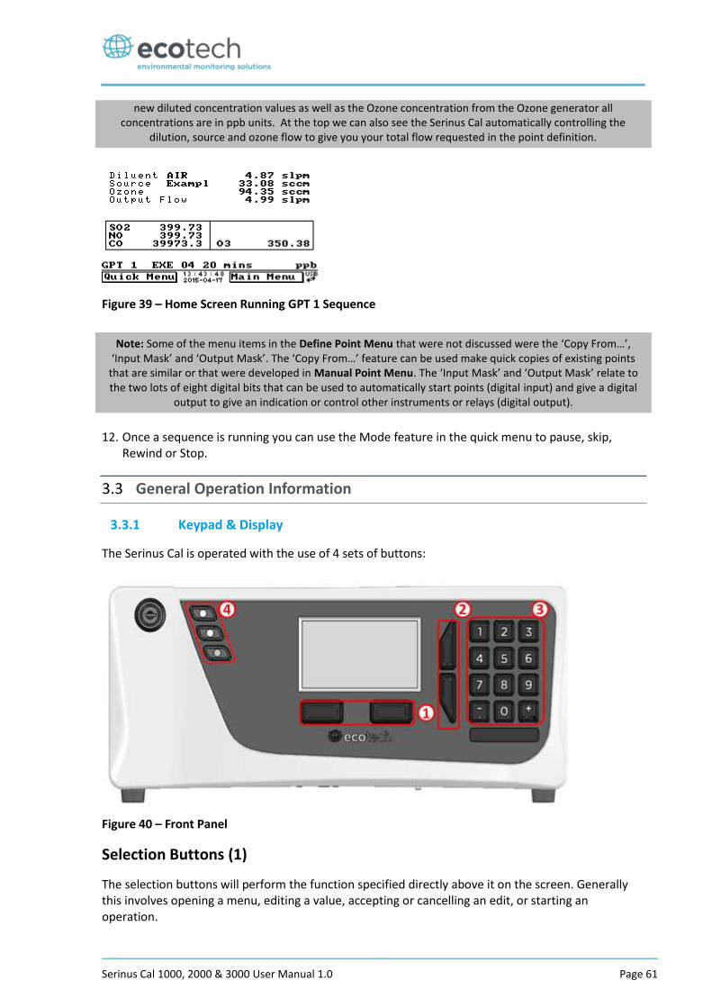
Serinus Cal 1000, 2000 & 3000 User Manual 1.0 Page 61
new diluted concentration values as well as the Ozone concentration from the Ozone generator all concentrations are in ppb units. At the top we can also see the Serinus Cal automatically controlling the
dilution, source and ozone flow to give you your total flow requested in the point definition.
Figure 39 – Home Screen Running GPT 1 Sequence
Note: Some of the menu items in the Define Point Menu that were not discussed were the ‘Copy From…’, ‘Input Mask’ and ‘Output Mask’. The ‘Copy From…’ feature can be used make quick copies of existing points
that are similar or that were developed in Manual Point Menu. The ‘Input Mask’ and ‘Output Mask’ relate to the two lots of eight digital bits that can be used to automatically start points (digital input) and give a digital
output to give an indication or control other instruments or relays (digital output).
12. Once a sequence is running you can use the Mode feature in the quick menu to pause, skip, Rewind or Stop.
3.3 General Operation Information
3.3.1 Keypad & Display
The Serinus Cal is operated with the use of 4 sets of buttons:
Figure 40 – Front Panel
Selection Buttons (1)
The selection buttons will perform the function specified directly above it on the screen. Generally this involves opening a menu, editing a value, accepting or cancelling an edit, or starting an operation.
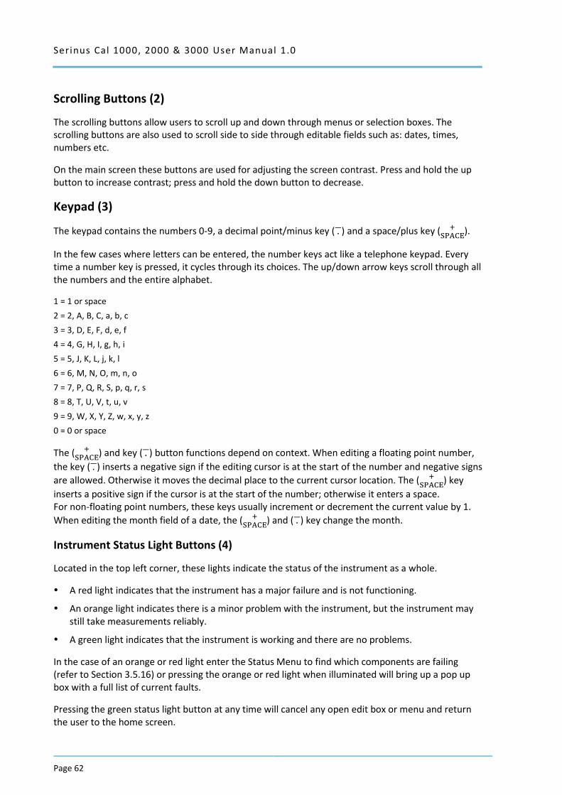
Serinus Cal 1000, 2000 & 3000 User Manual 1.0
Page 62
Scrolling Buttons (2)
The scrolling buttons allow users to scroll up and down through menus or selection boxes. The scrolling buttons are also used to scroll side to side through editable fields such as: dates, times, numbers etc.
On the main screen these buttons are used for adjusting the screen contrast. Press and hold the up button to increase contrast; press and hold the down button to decrease.
Keypad (3)
The keypad contains the numbers 0-9, a decimal point/minus key ( . ̅) and a space/plus key ( +SPACE
).
In the few cases where letters can be entered, the number keys act like a telephone keypad. Every time a number key is pressed, it cycles through its choices. The up/down arrow keys scroll through all the numbers and the entire alphabet.
1 = 1 or space
2 = 2, A, B, C, a, b, c
3 = 3, D, E, F, d, e, f
4 = 4, G, H, I, g, h, i
5 = 5, J, K, L, j, k, l
6 = 6, M, N, O, m, n, o
7 = 7, P, Q, R, S, p, q, r, s
8 = 8, T, U, V, t, u, v
9 = 9, W, X, Y, Z, w, x, y, z
0 = 0 or space
The ( +SPACE
) and key ( . ̅) button functions depend on context. When editing a floating point number,
the key ( . ̅) inserts a negative sign if the editing cursor is at the start of the number and negative signs
are allowed. Otherwise it moves the decimal place to the current cursor location. The ( +SPACE
) key
inserts a positive sign if the cursor is at the start of the number; otherwise it enters a space. For non-floating point numbers, these keys usually increment or decrement the current value by 1.
When editing the month field of a date, the ( +SPACE
) and ( . ̅) key change the month.
Instrument Status Light Buttons (4)
Located in the top left corner, these lights indicate the status of the instrument as a whole.
A red light indicates that the instrument has a major failure and is not functioning.
An orange light indicates there is a minor problem with the instrument, but the instrument may still take measurements reliably.
A green light indicates that the instrument is working and there are no problems.
In the case of an orange or red light enter the Status Menu to find which components are failing (refer to Section 3.5.16) or pressing the orange or red light when illuminated will bring up a pop up box with a full list of current faults.
Pressing the green status light button at any time will cancel any open edit box or menu and return the user to the home screen.
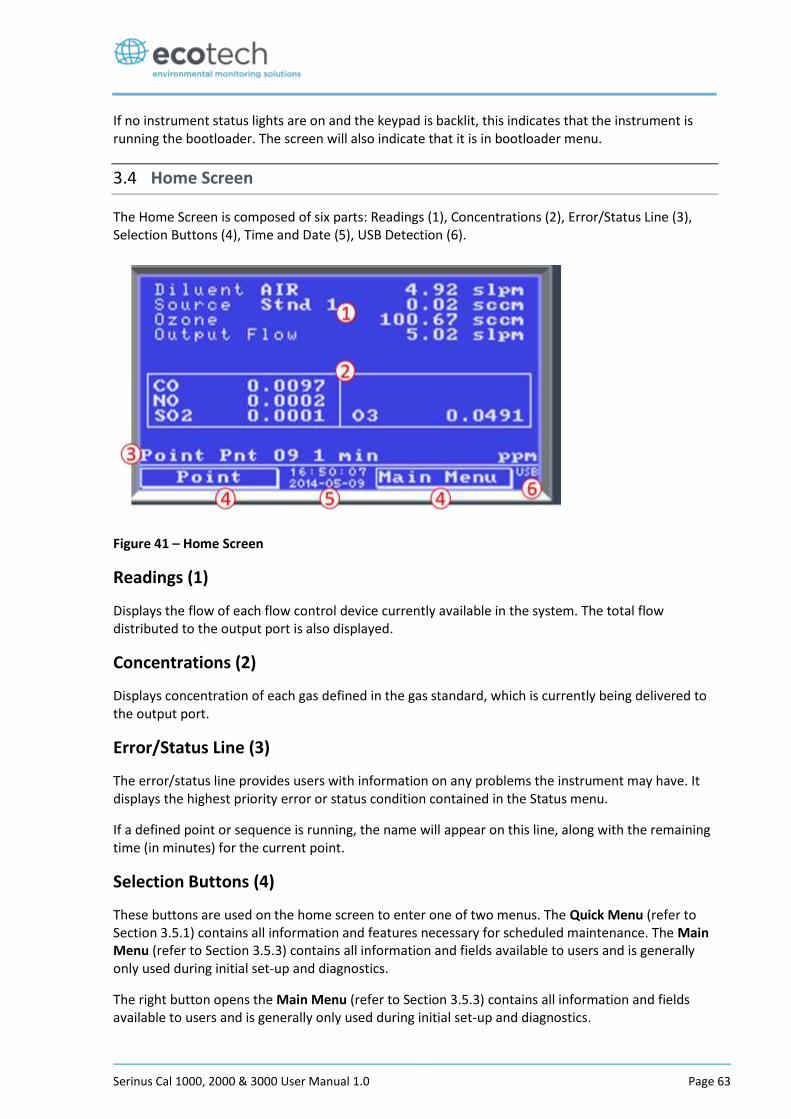
Serinus Cal 1000, 2000 & 3000 User Manual 1.0 Page 63
If no instrument status lights are on and the keypad is backlit, this indicates that the instrument is running the bootloader. The screen will also indicate that it is in bootloader menu.
3.4 Home Screen
The Home Screen is composed of six parts: Readings (1), Concentrations (2), Error/Status Line (3), Selection Buttons (4), Time and Date (5), USB Detection (6).
Figure 41 – Home Screen
Readings (1)
Displays the flow of each flow control device currently available in the system. The total flow distributed to the output port is also displayed.
Concentrations (2)
Displays concentration of each gas defined in the gas standard, which is currently being delivered to the output port.
Error/Status Line (3)
The error/status line provides users with information on any problems the instrument may have. It displays the highest priority error or status condition contained in the Status menu.
If a defined point or sequence is running, the name will appear on this line, along with the remaining time (in minutes) for the current point.
Selection Buttons (4)
These buttons are used on the home screen to enter one of two menus. The Quick Menu (refer to Section 3.5.1) contains all information and features necessary for scheduled maintenance. The Main Menu (refer to Section 3.5.3) contains all information and fields available to users and is generally only used during initial set-up and diagnostics.
The right button opens the Main Menu (refer to Section 3.5.3) contains all information and fields available to users and is generally only used during initial set-up and diagnostics.
Serinus Cal 1000, 2000 & 3000 User Manual 1.0
Page 64
Time and Date (5)
The time and date are displayed in between the menu buttons at the bottom of the screen.
USB Detection (6)
A USB symbol will be displayed in the bottom right corner when the USB memory stick is plugged in (the USB socket is behind the front panel). If the USB symbol is not shown the USB memory stick should be inserted. Underneath the USB symbol arrows may be displayed which indicates data transfer. The USB memory stick must not be removed whilst the arrows are visible.
Note: To safely remove the USB memory stick, navigate to the Service Menu and use the Safely Remove USB Stick function (refer to Section 3.5.25).
3.5 Menus & Screens
To begin using the Serinus Cal, a number of parameters must be programmed into the unit through the menu system. This section of the manual gives an overview of the menu system to the user. To access these items press the Menu button while on the home screen.
In general, editable parameters are displayed in bold font. Non-editable information is displayed in a thin font.
Some parameters may become editable based on the state of the instrument.
Sub-menus will be indicated with a small arrow; pressing the right-hand button on these items will open a new menu or a dialog box.
3.5.1 Quick Menu
The Quick Menu contains all the maintenance tools in one easy to use screen. It allows operators to perform calibrations, check important parameters and review the service history.
Mode Allows the user to select a mode of operation. Refer to Section 3.5.2
Event Log This field enters a screen with a log of all the events that the instrument has performed. These events include errors and warnings. This log is stored on the removable USB memory stick.
The log is organised by month. When you enter this screen you will be prompted to enter the month for which you wish to view events.
Instrument This field allows the instrument to be set to either Online (normal instrument operation) or In Maintenance (data is flagged as invalid).
Safely Remove USB Stick Always select this menu item before removing the USB memory stick or select the same menu item from the Service Menu (refer to Section 3.5.25). Failure to do this may cause corruption of the memory stick.
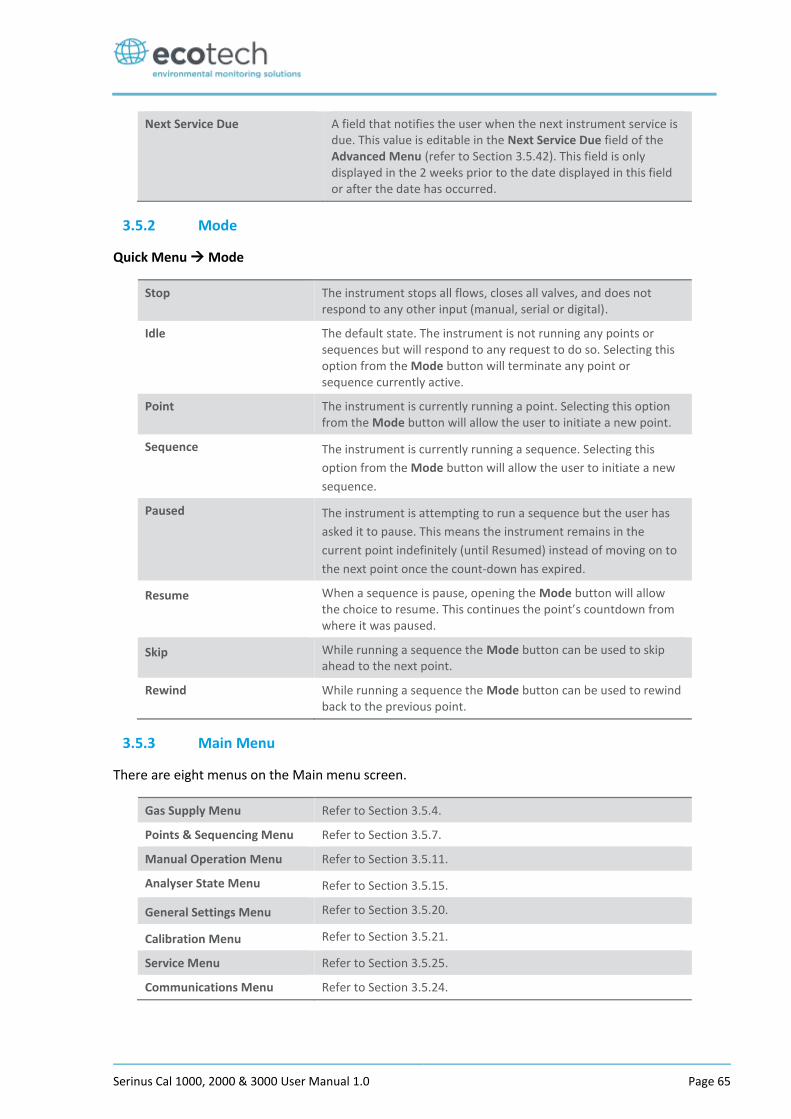
Serinus Cal 1000, 2000 & 3000 User Manual 1.0 Page 65
Next Service Due A field that notifies the user when the next instrument service is due. This value is editable in the Next Service Due field of the Advanced Menu (refer to Section 3.5.42). This field is only displayed in the 2 weeks prior to the date displayed in this field or after the date has occurred.
3.5.2 Mode
Quick Menu Mode
Stop The instrument stops all flows, closes all valves, and does not respond to any other input (manual, serial or digital).
Idle The default state. The instrument is not running any points or sequences but will respond to any request to do so. Selecting this option from the Mode button will terminate any point or sequence currently active.
Point The instrument is currently running a point. Selecting this option from the Mode button will allow the user to initiate a new point.
Sequence The instrument is currently running a sequence. Selecting this
option from the Mode button will allow the user to initiate a new
sequence.
Paused The instrument is attempting to run a sequence but the user has
asked it to pause. This means the instrument remains in the
current point indefinitely (until Resumed) instead of moving on to
the next point once the count-down has expired.
Resume When a sequence is pause, opening the Mode button will allow the choice to resume. This continues the point’s countdown from where it was paused.
Skip While running a sequence the Mode button can be used to skip ahead to the next point.
Rewind While running a sequence the Mode button can be used to rewind back to the previous point.
3.5.3 Main Menu
There are eight menus on the Main menu screen.
Gas Supply Menu Refer to Section 3.5.4.
Points & Sequencing Menu Refer to Section 3.5.7.
Manual Operation Menu Refer to Section 3.5.11.
Analyser State Menu Refer to Section 3.5.15.
General Settings Menu Refer to Section 3.5.20.
Calibration Menu Refer to Section 3.5.21.
Service Menu Refer to Section 3.5.25.
Communications Menu Refer to Section 3.5.24.
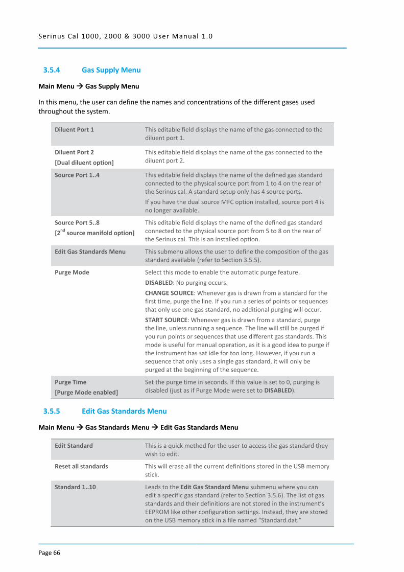
Serinus Cal 1000, 2000 & 3000 User Manual 1.0
Page 66
3.5.4 Gas Supply Menu
Main Menu Gas Supply Menu
In this menu, the user can define the names and concentrations of the different gases used throughout the system.
Diluent Port 1
This editable field displays the name of the gas connected to the diluent port 1.
Diluent Port 2
[Dual diluent option]
This editable field displays the name of the gas connected to the diluent port 2.
Source Port 1..4 This editable field displays the name of the defined gas standard connected to the physical source port from 1 to 4 on the rear of the Serinus cal. A standard setup only has 4 source ports.
If you have the dual source MFC option installed, source port 4 is no longer available.
Source Port 5..8
[2nd
source manifold option]
This editable field displays the name of the defined gas standard connected to the physical source port from 5 to 8 on the rear of the Serinus cal. This is an installed option.
Edit Gas Standards Menu This submenu allows the user to define the composition of the gas standard available (refer to Section 3.5.5).
Purge Mode Select this mode to enable the automatic purge feature.
DISABLED: No purging occurs.
CHANGE SOURCE: Whenever gas is drawn from a standard for the first time, purge the line. If you run a series of points or sequences that only use one gas standard, no additional purging will occur.
START SOURCE: Whenever gas is drawn from a standard, purge the line, unless running a sequence. The line will still be purged if you run points or sequences that use different gas standards. This mode is useful for manual operation, as it is a good idea to purge if the instrument has sat idle for too long. However, if you run a sequence that only uses a single gas standard, it will only be purged at the beginning of the sequence.
Purge Time
[Purge Mode enabled]
Set the purge time in seconds. If this value is set to 0, purging is disabled (just as if Purge Mode were set to DISABLED).
3.5.5 Edit Gas Standards Menu
Main Menu Gas Standards Menu Edit Gas Standards Menu
Edit Standard This is a quick method for the user to access the gas standard they wish to edit.
Reset all standards This will erase all the current definitions stored in the USB memory stick.
Standard 1..10 Leads to the Edit Gas Standard Menu submenu where you can edit a specific gas standard (refer to Section 3.5.6). The list of gas standards and their definitions are not stored in the instrument’s EEPROM like other configuration settings. Instead, they are stored on the USB memory stick in a file named “Standard.dat.”
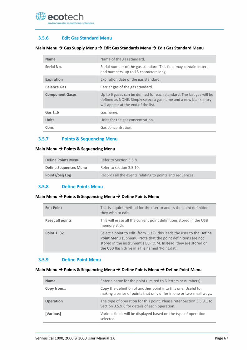
Serinus Cal 1000, 2000 & 3000 User Manual 1.0 Page 67
3.5.6 Edit Gas Standard Menu
Main Menu Gas Supply Menu Edit Gas Standards Menu Edit Gas Standard Menu
Name Name of the gas standard.
Serial No. Serial number of the gas standard. This field may contain letters and numbers, up to 15 characters long.
Expiration Expiration date of the gas standard.
Balance Gas Carrier gas of the gas standard.
Component Gases Up to 6 gases can be defined for each standard. The last gas will be defined as NONE. Simply select a gas name and a new blank entry will appear at the end of the list.
Gas 1..6 Gas name.
Units Units for the gas concentration.
Conc Gas concentration.
3.5.7 Points & Sequencing Menu
Main Menu Points & Sequencing Menu
Define Points Menu Refer to Section 3.5.8.
Define Sequences Menu Refer to section 3.5.10.
Points/Seq Log Records all the events relating to points and sequences.
3.5.8 Define Points Menu
Main Menu Points & Sequencing Menu Define Points Menu
Edit Point This is a quick method for the user to access the point definition they wish to edit.
Reset all points This will erase all the current point definitions stored in the USB memory stick.
Point 1..32 Select a point to edit (from 1-32), this leads the user to the Define Point Menu submenu. Note that the point definitions are not stored in the instrument’s EEPROM. Instead, they are stored on the USB flash drive in a file named ‘Point.dat’.
3.5.9 Define Point Menu
Main Menu Points & Sequencing Menu Define Points Menu Define Point Menu
Name Enter a name for the point (limited to 6 letters or numbers).
Copy from… Copy the definition of another point into this one. Useful for making a series of points that only differ in one or two small ways.
Operation The type of operation for this point. Please refer Section 3.5.9.1 to Section 3.5.9.6 for details of each operation.
[Various] Various fields will be displayed based on the type of operation selected.
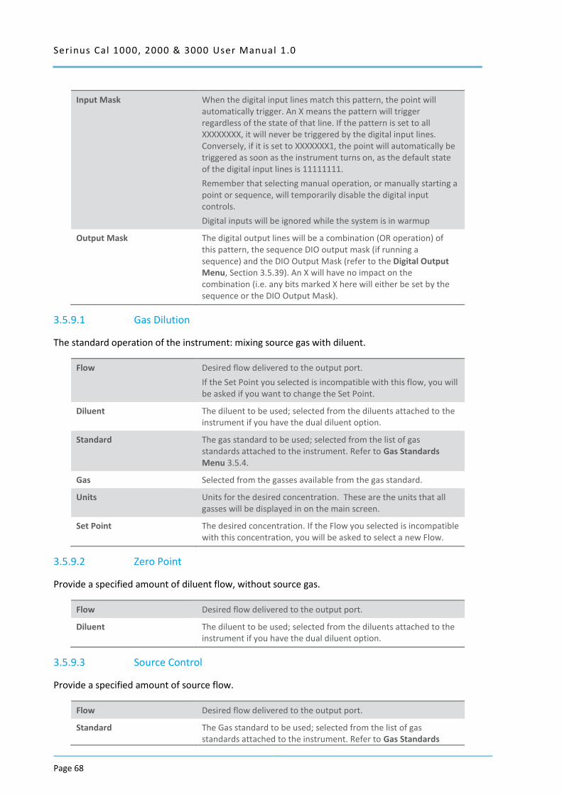
Serinus Cal 1000, 2000 & 3000 User Manual 1.0
Page 68
Input Mask When the digital input lines match this pattern, the point will automatically trigger. An X means the pattern will trigger regardless of the state of that line. If the pattern is set to all XXXXXXXX, it will never be triggered by the digital input lines. Conversely, if it is set to XXXXXXX1, the point will automatically be triggered as soon as the instrument turns on, as the default state of the digital input lines is 11111111.
Remember that selecting manual operation, or manually starting a point or sequence, will temporarily disable the digital input controls.
Digital inputs will be ignored while the system is in warmup
Output Mask The digital output lines will be a combination (OR operation) of this pattern, the sequence DIO output mask (if running a sequence) and the DIO Output Mask (refer to the Digital Output Menu, Section 3.5.39). An X will have no impact on the combination (i.e. any bits marked X here will either be set by the sequence or the DIO Output Mask).
3.5.9.1 Gas Dilution
The standard operation of the instrument: mixing source gas with diluent.
Flow Desired flow delivered to the output port.
If the Set Point you selected is incompatible with this flow, you will be asked if you want to change the Set Point.
Diluent The diluent to be used; selected from the diluents attached to the instrument if you have the dual diluent option.
Standard The gas standard to be used; selected from the list of gas standards attached to the instrument. Refer to Gas Standards Menu 3.5.4.
Gas Selected from the gasses available from the gas standard.
Units Units for the desired concentration. These are the units that all gasses will be displayed in on the main screen.
Set Point The desired concentration. If the Flow you selected is incompatible with this concentration, you will be asked to select a new Flow.
3.5.9.2 Zero Point
Provide a specified amount of diluent flow, without source gas.
Flow Desired flow delivered to the output port.
Diluent The diluent to be used; selected from the diluents attached to the instrument if you have the dual diluent option.
3.5.9.3 Source Control
Provide a specified amount of source flow.
Flow Desired flow delivered to the output port.
Standard The Gas standard to be used; selected from the list of gas standards attached to the instrument. Refer to Gas Standards
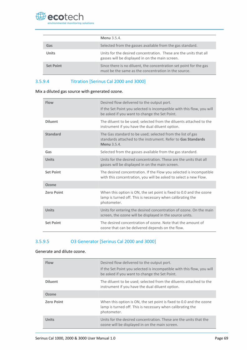
Serinus Cal 1000, 2000 & 3000 User Manual 1.0 Page 69
Menu 3.5.4.
Gas Selected from the gasses available from the gas standard.
Units Units for the desired concentration. These are the units that all gasses will be displayed in on the main screen.
Set Point Since there is no diluent, the concentration set point for the gas must be the same as the concentration in the source.
3.5.9.4 Titration [Serinus Cal 2000 and 3000]
Mix a diluted gas source with generated ozone.
Flow Desired flow delivered to the output port.
If the Set Point you selected is incompatible with this flow, you will be asked if you want to change the Set Point.
Diluent The diluent to be used; selected from the diluents attached to the instrument if you have the dual diluent option.
Standard The Gas standard to be used; selected from the list of gas standards attached to the instrument. Refer to Gas Standards Menu 3.5.4.
Gas Selected from the gasses available from the gas standard.
Units Units for the desired concentration. These are the units that all gasses will be displayed in on the main screen.
Set Point The desired concentration. If the Flow you selected is incompatible with this concentration, you will be asked to select a new Flow.
Ozone
Zero Point When this option is ON, the set point is fixed to 0.0 and the ozone lamp is turned off. This is necessary when calibrating the photometer.
Units Units for entering the desired concentration of ozone. On the main screen, the ozone will be displayed in the source units.
Set Point The desired concentration of ozone. Note that the amount of ozone that can be delivered depends on the flow.
3.5.9.5 O3 Generator [Serinus Cal 2000 and 3000]
Generate and dilute ozone.
Flow Desired flow delivered to the output port.
If the Set Point you selected is incompatible with this flow, you will be asked if you want to change the Set Point.
Diluent The diluent to be used; selected from the diluents attached to the instrument if you have the dual diluent option.
Ozone
Zero Point When this option is ON, the set point is fixed to 0.0 and the ozone lamp is turned off. This is necessary when calibrating the photometer.
Units Units for the desired concentration. These are the units that the ozone will be displayed in on the main screen.
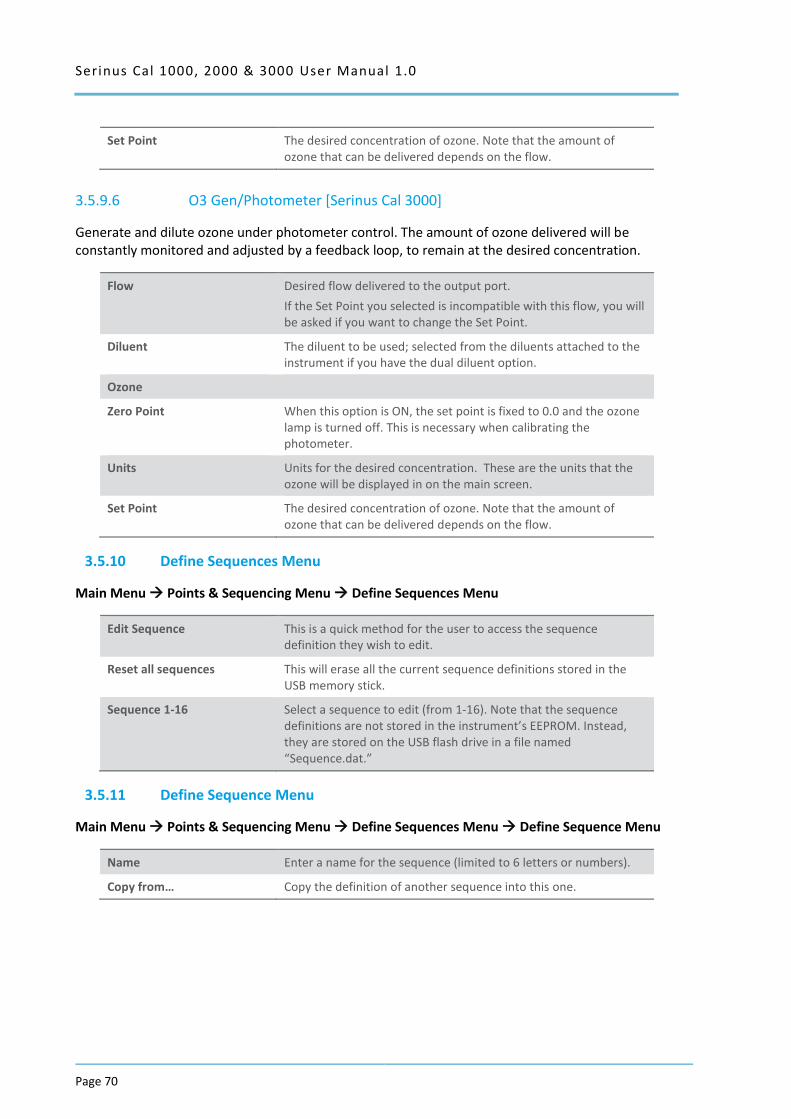
Serinus Cal 1000, 2000 & 3000 User Manual 1.0
Page 70
Set Point The desired concentration of ozone. Note that the amount of ozone that can be delivered depends on the flow.
3.5.9.6 O3 Gen/Photometer [Serinus Cal 3000]
Generate and dilute ozone under photometer control. The amount of ozone delivered will be constantly monitored and adjusted by a feedback loop, to remain at the desired concentration.
Flow Desired flow delivered to the output port.
If the Set Point you selected is incompatible with this flow, you will be asked if you want to change the Set Point.
Diluent The diluent to be used; selected from the diluents attached to the instrument if you have the dual diluent option.
Ozone
Zero Point When this option is ON, the set point is fixed to 0.0 and the ozone lamp is turned off. This is necessary when calibrating the photometer.
Units Units for the desired concentration. These are the units that the ozone will be displayed in on the main screen.
Set Point The desired concentration of ozone. Note that the amount of ozone that can be delivered depends on the flow.
3.5.10 Define Sequences Menu
Main Menu Points & Sequencing Menu Define Sequences Menu
Edit Sequence This is a quick method for the user to access the sequence definition they wish to edit.
Reset all sequences This will erase all the current sequence definitions stored in the USB memory stick.
Sequence 1-16 Select a sequence to edit (from 1-16). Note that the sequence definitions are not stored in the instrument’s EEPROM. Instead, they are stored on the USB flash drive in a file named “Sequence.dat.”
3.5.11 Define Sequence Menu
Main Menu Points & Sequencing Menu Define Sequences Menu Define Sequence Menu
Name Enter a name for the sequence (limited to 6 letters or numbers).
Copy from… Copy the definition of another sequence into this one.
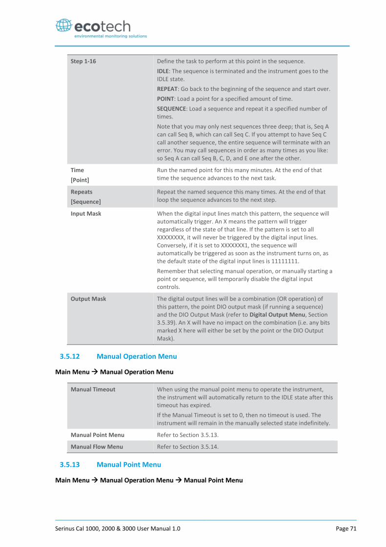
Serinus Cal 1000, 2000 & 3000 User Manual 1.0 Page 71
Step 1-16 Define the task to perform at this point in the sequence.
IDLE: The sequence is terminated and the instrument goes to the IDLE state.
REPEAT: Go back to the beginning of the sequence and start over.
POINT: Load a point for a specified amount of time.
SEQUENCE: Load a sequence and repeat it a specified number of times.
Note that you may only nest sequences three deep; that is, Seq A can call Seq B, which can call Seq C. If you attempt to have Seq C call another sequence, the entire sequence will terminate with an error. You may call sequences in order as many times as you like: so Seq A can call Seq B, C, D, and E one after the other.
Time
[Point]
Run the named point for this many minutes. At the end of that time the sequence advances to the next task.
Repeats
[Sequence]
Repeat the named sequence this many times. At the end of that loop the sequence advances to the next step.
Input Mask When the digital input lines match this pattern, the sequence will automatically trigger. An X means the pattern will trigger regardless of the state of that line. If the pattern is set to all XXXXXXXX, it will never be triggered by the digital input lines. Conversely, if it is set to XXXXXXX1, the sequence will automatically be triggered as soon as the instrument turns on, as the default state of the digital input lines is 11111111.
Remember that selecting manual operation, or manually starting a point or sequence, will temporarily disable the digital input controls.
Output Mask The digital output lines will be a combination (OR operation) of this pattern, the point DIO output mask (if running a sequence) and the DIO Output Mask (refer to Digital Output Menu, Section 3.5.39). An X will have no impact on the combination (i.e. any bits marked X here will either be set by the point or the DIO Output Mask).
3.5.12 Manual Operation Menu
Main Menu Manual Operation Menu
Manual Timeout When using the manual point menu to operate the instrument, the instrument will automatically return to the IDLE state after this timeout has expired.
If the Manual Timeout is set to 0, then no timeout is used. The instrument will remain in the manually selected state indefinitely.
Manual Point Menu Refer to Section 3.5.13.
Manual Flow Menu Refer to Section 3.5.14.
3.5.13 Manual Point Menu
Main Menu Manual Operation Menu Manual Point Menu

Serinus Cal 1000, 2000 & 3000 User Manual 1.0
Page 72
This menu allows the user to operate the instrument directly (without defining a point). This may be used when experimenting with points it can then later be copied into a permanent point definition with the “Copy from…” feature.
Mode This is the same as the Mode in the Quick Menu.
Operation The type of operation. Refer to Sections 3.5.9.1, 3.5.9.2, 3.5.9.3, 3.5.9.4 and 3.5.9.5 for operation descriptions.
[Various] Various fields will be displayed based on the type of operation selected.
Purge Manually initiate a purge of the source.
3.5.14 Manual Flow Menu
Main Menu Manual Operation Menu Manual Flow Menu
For calibration and test it is often necessary to directly control the MFC flows.
Gas Indicate which gas is being provided. This is used to calculate the MFC correction factor.
Diluent Port Select a diluent port to open. 0 indicates no port.
Source Port Select a source port to open. 0 indicates no port.
Purge Port Open the purge port for the specified amount of seconds. This value will count down and when it reaches 0 the purge port will be closed.
MFC Source Enter the desired flow for the source MFC (in sccm).
Flow Displays the measured flow for the above MFC.
MFC Opt Source Enter the desired flow for the optional 2nd source MFC (in sccm).
Flow Displays the measured flow for the above MFC.
MFC Diluent Enter the desired flow for the diluent MFC (in sccm).
Flow Displays the measured flow for the above MFC.
MFC Opt Diluent Enter the desired flow for the optional 2nd diluent MFC (in sccm).
Flow Displays the measured flow for the above MFC.
3.5.15 Analyser State Menu
Main Menu Analyser State Menu
This displays the status of various parameters that affect instrument measurements.
Status Menu Refer to Section 3.5.16.
Temperature Menu Refer to Section 3.5.17.
Pressure & Flow Menu Refer to Section 3.5.18.
Voltage Menu Refer to Section 3.5.19.
Model This field will always display Serinus.
Variant The variant of the Serinus Cal model. (i.e. 1000, 2000 or 3000).
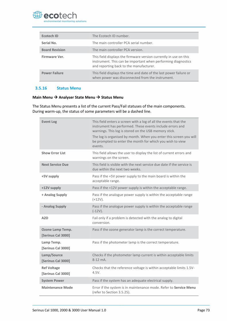
Serinus Cal 1000, 2000 & 3000 User Manual 1.0 Page 73
Ecotech ID The Ecotech ID number.
Serial No. The main controller PCA serial number.
Board Revision The main controller PCA version.
Firmware Ver. This field displays the firmware version currently in use on this instrument. This can be important when performing diagnostics and reporting back to the manufacturer.
Power Failure This field displays the time and date of the last power failure or when power was disconnected from the instrument.
3.5.16 Status Menu
Main Menu Analyser State Menu Status Menu
The Status Menu presents a list of the current Pass/Fail statuses of the main components. During warm-up, the status of some parameters will be a dashed line.
Event Log This field enters a screen with a log of all the events that the instrument has performed. These events include errors and warnings. This log is stored on the USB memory stick.
The log is organised by month. When you enter this screen you will be prompted to enter the month for which you wish to view events.
Show Error List This field allows the user to display the list of current errors and warnings on the screen.
Next Service Due This field is visible with the next service due date if the service is due within the next two weeks.
+5V supply Pass if the +5V power supply to the main board is within the acceptable range.
+12V supply Pass if the +12V power supply is within the acceptable range.
+ Analog Supply Pass if the analogue power supply is within the acceptable range (+12V).
- Analog Supply Pass if the analogue power supply is within the acceptable range (-12V).
A2D Fail only if a problem is detected with the analog to digital conversion.
Ozone Lamp Temp.
[Serinus Cal 3000]
Pass if the ozone generator lamp is the correct temperature.
Lamp Temp.
[Serinus Cal 3000]
Pass if the photometer lamp is the correct temperature.
Lamp/Source
[Serinus Cal 3000]
Checks if the photometer lamp current is within acceptable limits 8-12 mA.
Ref Voltage
[Serinus Cal 3000]
Checks that the reference voltage is within acceptable limits 1.5V-4.5V.
System Power Pass if the system has an adequate electrical supply.
Maintenance Mode Error if the system is in maintenance mode. Refer to Service Menu (refer to Section 3.5.25).
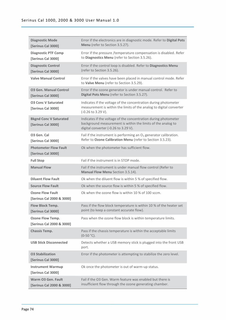
Serinus Cal 1000, 2000 & 3000 User Manual 1.0
Page 74
Diagnostic Mode
[Serinus Cal 3000]
Error if the electronics are in diagnostic mode. Refer to Digital Pots Menu (refer to Section 3.5.27).
Diagnostic PTF Comp
[Serinus Cal 3000]
Error if the pressure /temperature compensation is disabled. Refer to Diagnostics Menu (refer to Section 3.5.26).
Diagnostic Control
[Serinus Cal 3000]
Error if the control loop is disabled. Refer to Diagnostics Menu (refer to Section 3.5.26).
Valve Manual Control Error if the valves have been placed in manual control mode. Refer to Valve Menu (refer to Section 3.5.29).
O3 Gen. Manual Control
[Serinus Cal 3000]
Error if the ozone generator is under manual control. Refer to Digital Pots Menu (refer to Section 3.5.27).
O3 Conc V Saturated
[Serinus Cal 3000]
Indicates if the voltage of the concentration during photometer measurement is within the limits of the analog to digital converter (-0.26 to 3.29 V).
Bkgnd Conc V Saturated
[Serinus Cal 3000]
Indicates if the voltage of the concentration during photometer background measurement is within the limits of the analog to digital converter (-0.26 to 3.29 V).
O3 Gen. Cal
[Serinus Cal 3000]
Fail if the instrument is performing an O3 generator calibration. Refer to Ozone Calibration Menu (refer to Section 3.5.23).
Photometer Flow Fault
[Serinus Cal 3000]
Ok when the photometer has sufficient flow.
Full Stop Fail if the instrument is in STOP mode.
Manual Flow Fail if the instrument is under manual flow control (Refer to Manual Flow Menu Section 3.5.14).
Diluent Flow Fault Ok when the diluent flow is within 5 % of specified flow.
Source Flow Fault Ok when the source flow is within 5 % of specified flow.
Ozone Flow Fault
[Serinus Cal 2000 & 3000]
Ok when the ozone flow is within 10 % of 100 sccm.
Flow Block Temp.
[Serinus Cal 3000]
Pass if the flow block temperature is within 10 % of the heater set point (to keep a constant accurate flow).
Ozone Flow Temp.
[Serinus Cal 2000 & 3000]
Pass when the ozone flow block is within temperature limits.
Chassis Temp. Pass if the chassis temperature is within the acceptable limits (0-50 °C).
USB Stick Disconnected Detects whether a USB memory stick is plugged into the front USB port.
O3 Stabilization
[Serinus Cal 3000]
Error if the photometer is attempting to stabilize the zero level.
Instrument Warmup
[Serinus Cal 3000]
Ok once the photometer is out of warm-up status.
Warm O3 Gen. Fault
[Serinus Cal 2000 & 3000]
Fail if the O3 Gen. Warm feature was enabled but there is insufficient flow through the ozone generating chamber.

Serinus Cal 1000, 2000 & 3000 User Manual 1.0 Page 75
3.5.17 Temperature Menu
Main Menu Analyser State Menu Temperature Menu
Temperature Units The current temperature units of the analyser (Celsius,
Fahrenheit, or Kelvin).
Set Point (LAMP)
[Serinus Cal 3000]
The temperature set point of the photometer UV lamp. The factory default is 50 °C.
Set Point (FLOW)
[Serinus Cal 3000]
The temperature set point of the flow block heater. The factory default is 50 °C.
Set Point (O3 GEN)
[Serinus Cal 2000 & 3000]
The temperature set point of the ozone generating lamp. The factory default is 50 °C.
Set Point (O3 flow)
[Serinus Cal 2000 & 3000]
The temperature set point of the ozone flow block. The factory default is 50 °C.
Lamp
[Serinus Cal 3000]
The current temperature of the photometer lamp.
Flow Block
[Serinus Cal 3000]
The current temperature of the flow block.
Chassis The current temperature of air inside the chassis, measured on the main controller PCA.
O3 Gen
[Serinus Cal 2000 & 3000]
The current temperature of the ozone generator.
O3 Flow
[Serinus Cal 2000 & 3000]
The current temperature of the ozone flow block.
3.5.18 Pressure & Flow Menu
Main Menu Analyser State Menu Pressure & Flow Menu
Pressure Units Select the units that the pressure will be displayed in (torr, PSI,
mBar, ATM, kPa).
Ambient Current ambient pressure.
Cell
[Serinus Cal 3000]
Current photometer cell pressure.
Internal Pump
[Serinus Cal 3000]
Current photometer pumps pressure.
Photometer
[Serinus Cal 3000]
The current photometer flow.
Diluent The gas flow through the diluent MFC.
Source The gas flow through the source MFC.
Ozone
[Serinus Cal 2000 & 3000]
The current ozone flow.
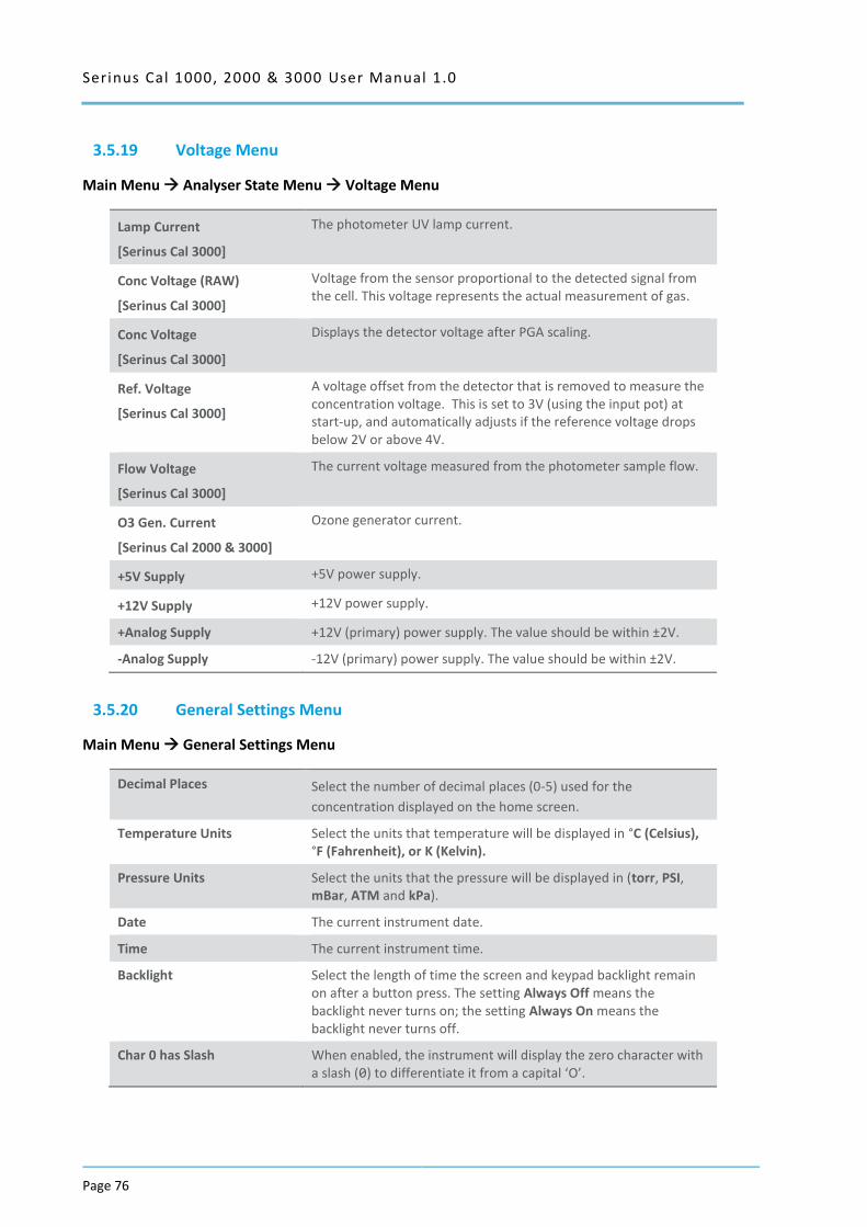
Serinus Cal 1000, 2000 & 3000 User Manual 1.0
Page 76
3.5.19 Voltage Menu
Main Menu Analyser State Menu Voltage Menu
Lamp Current
[Serinus Cal 3000]
The photometer UV lamp current.
Conc Voltage (RAW)
[Serinus Cal 3000]
Voltage from the sensor proportional to the detected signal from the cell. This voltage represents the actual measurement of gas.
Conc Voltage
[Serinus Cal 3000]
Displays the detector voltage after PGA scaling.
Ref. Voltage
[Serinus Cal 3000]
A voltage offset from the detector that is removed to measure the concentration voltage. This is set to 3V (using the input pot) at start-up, and automatically adjusts if the reference voltage drops below 2V or above 4V.
Flow Voltage
[Serinus Cal 3000]
The current voltage measured from the photometer sample flow.
O3 Gen. Current
[Serinus Cal 2000 & 3000]
Ozone generator current.
+5V Supply +5V power supply.
+12V Supply +12V power supply.
+Analog Supply +12V (primary) power supply. The value should be within ±2V.
-Analog Supply -12V (primary) power supply. The value should be within ±2V.
3.5.20 General Settings Menu
Main Menu General Settings Menu
Decimal Places Select the number of decimal places (0-5) used for the
concentration displayed on the home screen.
Temperature Units Select the units that temperature will be displayed in °C (Celsius), °F (Fahrenheit), or K (Kelvin).
Pressure Units Select the units that the pressure will be displayed in (torr, PSI, mBar, ATM and kPa).
Date The current instrument date.
Time The current instrument time.
Backlight Select the length of time the screen and keypad backlight remain on after a button press. The setting Always Off means the backlight never turns on; the setting Always On means the backlight never turns off.
Char 0 has Slash When enabled, the instrument will display the zero character with a slash (0) to differentiate it from a capital ‘O’.

Serinus Cal 1000, 2000 & 3000 User Manual 1.0 Page 77
3.5.21 Calibration Menu
Main Menu Calibration Menu
Photometer
[Serinus Cal 3000]
Displays the current photometer reading.
Span calibrate O3
[Serinus Cal 3000]
Calibrate the photometer to the span point to the current reading.
Zero calibrate O3
[Serinus Cal 3000]
Calibrate the zero point to the current reading.
Pressure Calibration Menu Refer to section 3.5.22.
Ozone Calibration Menu
[Serinus Cal 2000 & 3000]
Refer to Section 3.5.23.
Pressure O3
[Serinus Cal 3000]
The instrument cell pressure in the photometer during the last
calibration.
Temperature
[Serinus Cal 3000]
The instrument temperature during the last calibration.
3.5.22 Pressure Calibration Menu
Main Menu Calibration Menu Pressure Calibration Menu
Vacuum Set Pt.
[Serinus Cal 3000]
The zero point for the calibration. Activating this item will open a
dialog box of instructions. Refer to Section 5.3 for the calibration
procedure.
Ambient Set Pt. The high point for the calibration. Activating this item will open a
dialog box of instructions. Refer to Section 5.3 for the calibration
procedure.
Pressure Units Select the units that the pressure will be displayed in (torr, PSI,
mBar, ATM or kPa).
Ambient The current ambient pressure (displayed in pressure units and as a
raw voltage).
Cell
[Serinus Cal 3000]
The current photometer reaction cell pressure (displayed in
pressure units and as a raw voltage).
Internal Pump
[Serinus Cal 3000]
The current internal pump pressure (displayed in pressure units
and as a raw voltage).
O3 Flow
[Serinus Cal 2000 & 3000]
Calibrates the ozone flow. Refer to Section 5.2 for the calibration
procedure.
3.5.23 Ozone Calibration Menu
Main Menu Calibration Menu Ozone Calibration Menu
Flow Specify the flow desired for the ozone calibration process.
Ozone Calibration Refer to Section 5.4 and Section 5.5 for the calibration procedures.
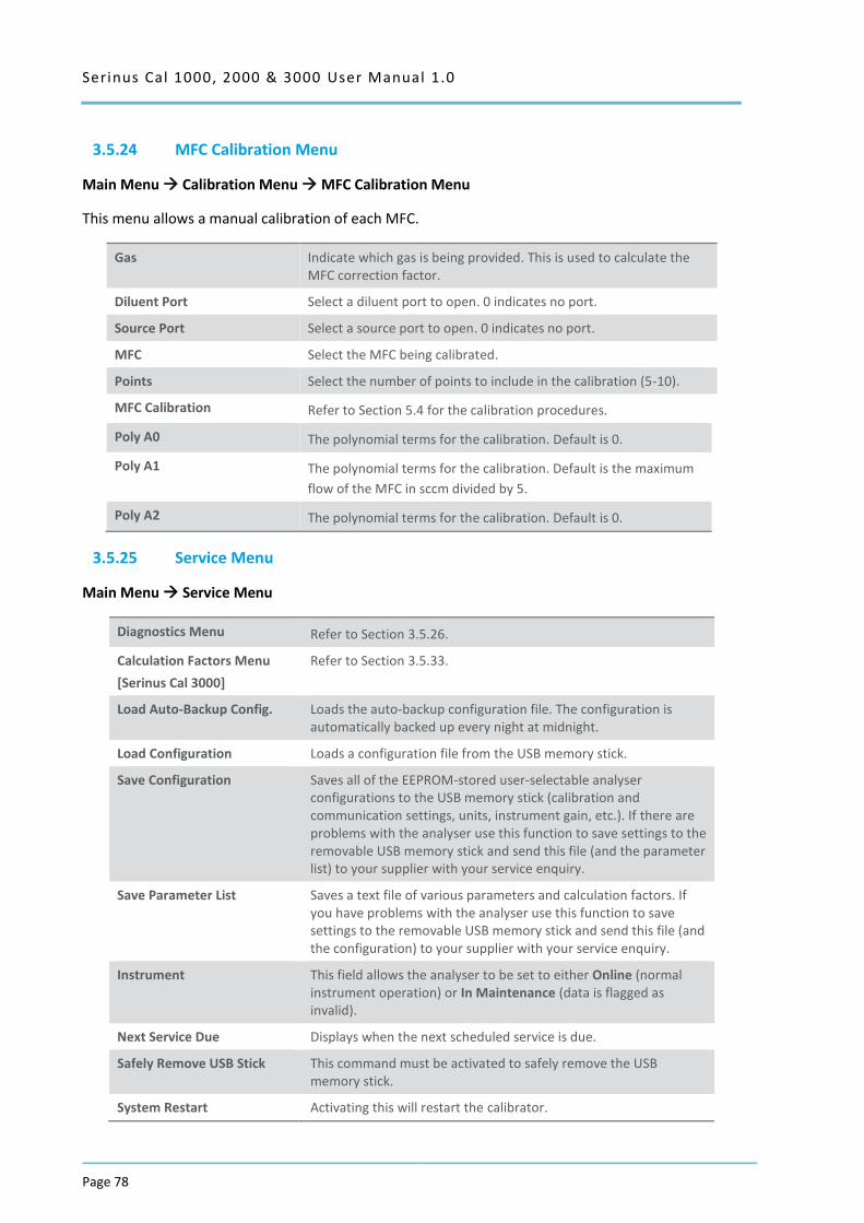
Serinus Cal 1000, 2000 & 3000 User Manual 1.0
Page 78
3.5.24 MFC Calibration Menu
Main Menu Calibration Menu MFC Calibration Menu
This menu allows a manual calibration of each MFC.
Gas Indicate which gas is being provided. This is used to calculate the MFC correction factor.
Diluent Port Select a diluent port to open. 0 indicates no port.
Source Port Select a source port to open. 0 indicates no port.
MFC Select the MFC being calibrated.
Points Select the number of points to include in the calibration (5-10).
MFC Calibration Refer to Section 5.4 for the calibration procedures.
Poly A0 The polynomial terms for the calibration. Default is 0.
Poly A1 The polynomial terms for the calibration. Default is the maximum
flow of the MFC in sccm divided by 5.
Poly A2 The polynomial terms for the calibration. Default is 0.
3.5.25 Service Menu
Main Menu Service Menu
Diagnostics Menu Refer to Section 3.5.26.
Calculation Factors Menu
[Serinus Cal 3000]
Refer to Section 3.5.33.
Load Auto-Backup Config. Loads the auto-backup configuration file. The configuration is automatically backed up every night at midnight.
Load Configuration Loads a configuration file from the USB memory stick.
Save Configuration Saves all of the EEPROM-stored user-selectable analyser configurations to the USB memory stick (calibration and communication settings, units, instrument gain, etc.). If there are problems with the analyser use this function to save settings to the removable USB memory stick and send this file (and the parameter list) to your supplier with your service enquiry.
Save Parameter List Saves a text file of various parameters and calculation factors. If you have problems with the analyser use this function to save settings to the removable USB memory stick and send this file (and the configuration) to your supplier with your service enquiry.
Instrument This field allows the analyser to be set to either Online (normal instrument operation) or In Maintenance (data is flagged as invalid).
Next Service Due Displays when the next scheduled service is due.
Safely Remove USB Stick This command must be activated to safely remove the USB memory stick.
System Restart Activating this will restart the calibrator.
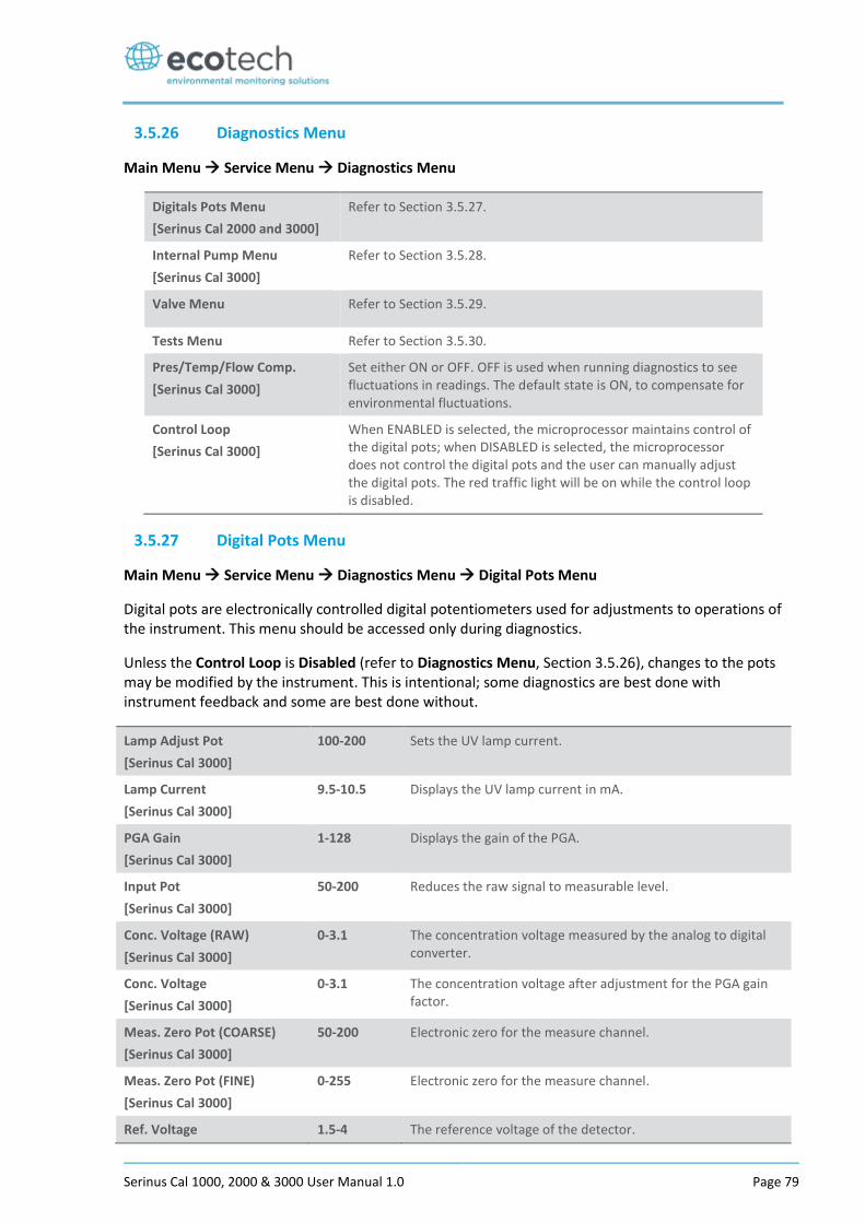
Serinus Cal 1000, 2000 & 3000 User Manual 1.0 Page 79
3.5.26 Diagnostics Menu
Main Menu Service Menu Diagnostics Menu
Digitals Pots Menu
[Serinus Cal 2000 and 3000]
Refer to Section 3.5.27.
Internal Pump Menu
[Serinus Cal 3000]
Refer to Section 3.5.28.
Valve Menu Refer to Section 3.5.29.
Tests Menu Refer to Section 3.5.30.
Pres/Temp/Flow Comp.
[Serinus Cal 3000]
Set either ON or OFF. OFF is used when running diagnostics to see fluctuations in readings. The default state is ON, to compensate for environmental fluctuations.
Control Loop
[Serinus Cal 3000]
When ENABLED is selected, the microprocessor maintains control of the digital pots; when DISABLED is selected, the microprocessor does not control the digital pots and the user can manually adjust the digital pots. The red traffic light will be on while the control loop is disabled.
3.5.27 Digital Pots Menu
Main Menu Service Menu Diagnostics Menu Digital Pots Menu
Digital pots are electronically controlled digital potentiometers used for adjustments to operations of the instrument. This menu should be accessed only during diagnostics.
Unless the Control Loop is Disabled (refer to Diagnostics Menu, Section 3.5.26), changes to the pots may be modified by the instrument. This is intentional; some diagnostics are best done with instrument feedback and some are best done without.
Lamp Adjust Pot
[Serinus Cal 3000]
100-200 Sets the UV lamp current.
Lamp Current
[Serinus Cal 3000]
9.5-10.5 Displays the UV lamp current in mA.
PGA Gain
[Serinus Cal 3000]
1-128 Displays the gain of the PGA.
Input Pot
[Serinus Cal 3000]
50-200 Reduces the raw signal to measurable level.
Conc. Voltage (RAW)
[Serinus Cal 3000]
0-3.1 The concentration voltage measured by the analog to digital converter.
Conc. Voltage
[Serinus Cal 3000]
0-3.1 The concentration voltage after adjustment for the PGA gain factor.
Meas. Zero Pot (COARSE)
[Serinus Cal 3000]
50-200 Electronic zero for the measure channel.
Meas. Zero Pot (FINE)
[Serinus Cal 3000]
0-255 Electronic zero for the measure channel.
Ref. Voltage 1.5-4 The reference voltage of the detector.
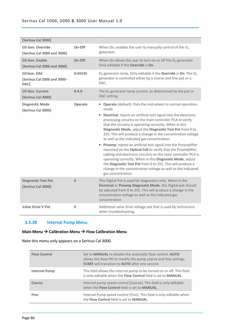
Serinus Cal 1000, 2000 & 3000 User Manual 1.0
Page 80
[Serinus Cal 3000]
O3 Gen. Override
[Serinus Cal 2000 and 3000]
On-Off When On, enables the user to manually control of the O3 generator.
O3 Gen. Enable
[Serinus Cal 2000 and 3000]
On-Off When On allows the user to turn on or off the O3 generator. Only editable if the Override is On.
O3 Gen. DAC
[Serinus Cal 2000 and 3000 - DAC]
0-65535 O3 generator lamp. Only editable if the Override is On. The O3 generator is controlled either by a coarse and fine pot or a DAC.
O3 Gen. Current
[Serinus Cal 3000]
0-4.9 The O3 generator lamp current, as determined by the pot or DAC setting.
Diagnostic Mode
[Serinus Cal 3000]
Operate Operate (default): Puts the instrument in normal operation mode.
Electrical: Injects an artificial test signal into the electronic processing circuitry on the main controller PCA to verify that the circuitry is operating correctly. When in this Diagnostic Mode, adjust the Diagnostic Test Pot from 0 to 255. This will produce a change in the concentration voltage as well as the indicated gas concentration.
Preamp: Injects an artificial test signal into the Preamplifier mounted on the Optical Cell to verify that the Preamplifier, cabling and electronic circuitry on the main controller PCA is operating correctly. When in this Diagnostic Mode, adjust the Diagnostic Test Pot from 0 to 255. This will produce a change in the concentration voltage as well as the indicated gas concentration.
Diagnostic Test Pot
[Serinus Cal 3000]
0 This Digital Pot is used for diagnostics only. When in the Electrical or Preamp Diagnostic Mode, this Digital pot should be adjusted from 0 to 255. This will produce a change in the concentration voltage as well as the indicated gas concentration.
Valve Drive V Pot 0 Additional valve drive voltage pot that is used by technicians when troubleshooting.
3.5.28 Internal Pump Menu
Main Menu Calibration Menu Flow Calibration Menu
Note this menu only appears on a Serinus Cal 3000.
Flow Control Set to MANUAL to disable the automatic flow control. AUTO allows the flow PID to modify the pump coarse and fine settings. START will transition to AUTO after one second.
Internal Pump This field allows the internal pump to be turned on or off. This field is only editable when the Flow Control field is set to MANUAL.
Coarse Internal pump speed control (Coarse). This field is only editable when the Flow Control field is set to MANUAL.
Fine Internal Pump speed control (Fine). This field is only editable when the Flow Control field is set to MANUAL.
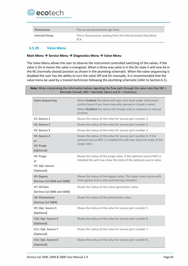
Serinus Cal 1000, 2000 & 3000 User Manual 1.0 Page 81
Photometer The current photometer gas flow.
Internal Pump This is the pressure reading from the internal pump flow block PCA.
3.5.29 Valve Menu
Main Menu Service Menu Diagnostics Menu Valve Menu
The Valve Menu allows the user to observe the instrument controlled switching of the valves. If the valve is On it means the valve is energised. When a three way valve is in the On state it will now be in the NC (normally closed) position as shown in the plumbing schematic. When the valve sequencing is disabled the user has the ability to turn the valve Off and On manually. It is recommended that the valve menu be used by a trained technician following the plumbing schematic (refer to Section 6.1).
Note: When interpreting the information below regarding the flow path through the valve note that (NC = Normally Closed), (NO = Normally Open) and (C = Common).
Valve Sequencing
When Enabled the valves will open and close under instrument control (even if you have manually opened or closed a valve).
When Disabled the valves will change only in response to manual controls.
V1: Source 1 Shows the status of the valve for source port number 1.
V2: Source 2 Shows the status of the valve for source port number 2.
V3: Source 3 Shows the status of the valve for source port number 3.
V4: Source 4
or
V4: Purge
[Optional]
Shows the status of the valve for source port number 4. If the optional source MFC is installed this will now show the state of the purge valve.
V5: Purge
or
V5: Opt. Source
[Optional]
Shows the status of the purge valve. If the optional source MFC is installed this will now show the state of the optional source valve.
V6: Bypass
[Serinus Cal 2000 and 3000]
Shows the status of the bypass valve. This valve mixes ozone with other gasses and is only used during a titration.
V7: O3 Gen.
[Serinus Cal 2000 and 3000]
Shows the status of the ozone generation valve.
V8: Photometer
[Serinus Cal 3000]
Shows the status of the photometer valve.
V9: Opt. Source 5
[Optional]
Shows the status of the valve for source port number 5.
V10: Opt. Source 6
[Optional]
Shows the status of the valve for source port number 6.
V11: Opt. Source 7
[Optional]
Shows the status of the valve for source port number 7.
V12: Opt. Source 8
[Optional]
Shows the status of the valve for source port number 8.
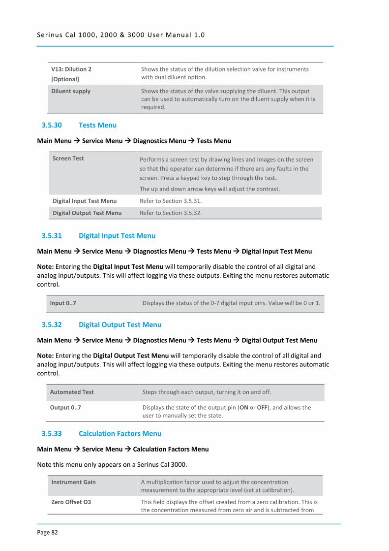
Serinus Cal 1000, 2000 & 3000 User Manual 1.0
Page 82
V13: Dilution 2
[Optional]
Shows the status of the dilution selection valve for instruments with dual diluent option.
Diluent supply Shows the status of the valve supplying the diluent. This output can be used to automatically turn on the diluent supply when it is required.
3.5.30 Tests Menu
Main Menu Service Menu Diagnostics Menu Tests Menu
Screen Test Performs a screen test by drawing lines and images on the screen
so that the operator can determine if there are any faults in the
screen. Press a keypad key to step through the test.
The up and down arrow keys will adjust the contrast.
Digital Input Test Menu Refer to Section 3.5.31.
Digital Output Test Menu Refer to Section 3.5.32.
3.5.31 Digital Input Test Menu
Main Menu Service Menu Diagnostics Menu Tests Menu Digital Input Test Menu
Note: Entering the Digital Input Test Menu will temporarily disable the control of all digital and analog input/outputs. This will affect logging via these outputs. Exiting the menu restores automatic control.
Input 0..7 Displays the status of the 0-7 digital input pins. Value will be 0 or 1.
3.5.32 Digital Output Test Menu
Main Menu Service Menu Diagnostics Menu Tests Menu Digital Output Test Menu
Note: Entering the Digital Output Test Menu will temporarily disable the control of all digital and analog input/outputs. This will affect logging via these outputs. Exiting the menu restores automatic control.
Automated Test Steps through each output, turning it on and off.
Output 0..7 Displays the state of the output pin (ON or OFF), and allows the user to manually set the state.
3.5.33 Calculation Factors Menu
Main Menu Service Menu Calculation Factors Menu
Note this menu only appears on a Serinus Cal 3000.
Instrument Gain A multiplication factor used to adjust the concentration measurement to the appropriate level (set at calibration).
Zero Offset O3 This field displays the offset created from a zero calibration. This is the concentration measured from zero air and is subtracted from
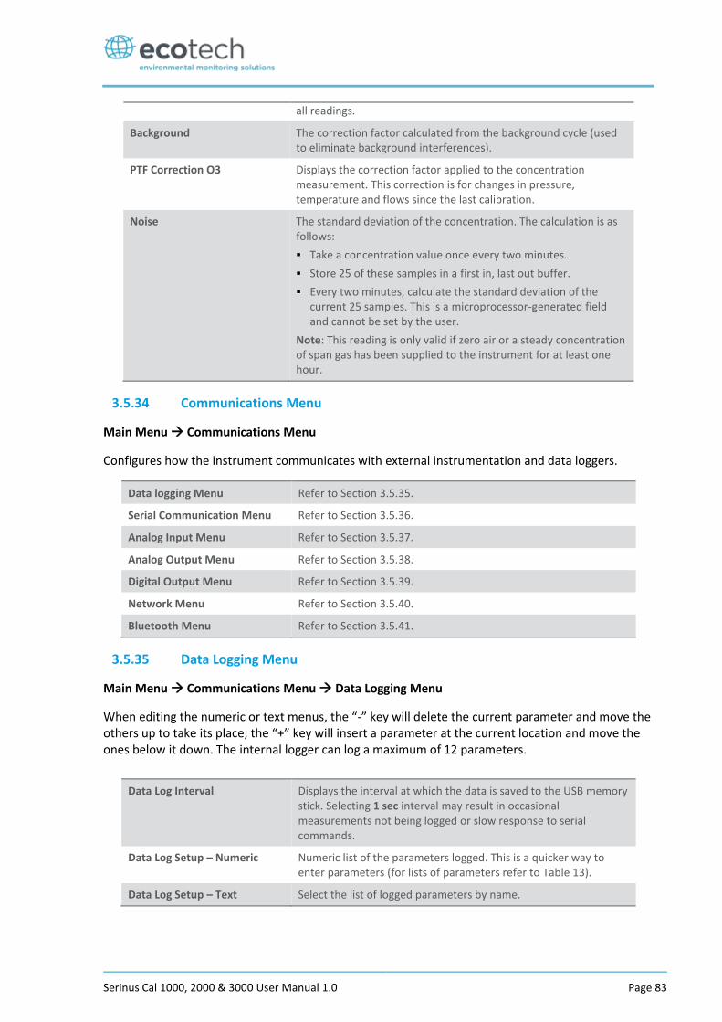
Serinus Cal 1000, 2000 & 3000 User Manual 1.0 Page 83
all readings.
Background The correction factor calculated from the background cycle (used to eliminate background interferences).
PTF Correction O3 Displays the correction factor applied to the concentration measurement. This correction is for changes in pressure, temperature and flows since the last calibration.
Noise The standard deviation of the concentration. The calculation is as follows:
Take a concentration value once every two minutes.
Store 25 of these samples in a first in, last out buffer.
Every two minutes, calculate the standard deviation of the current 25 samples. This is a microprocessor-generated field and cannot be set by the user.
Note: This reading is only valid if zero air or a steady concentration of span gas has been supplied to the instrument for at least one hour.
3.5.34 Communications Menu
Main Menu Communications Menu
Configures how the instrument communicates with external instrumentation and data loggers.
Data logging Menu Refer to Section 3.5.35.
Serial Communication Menu Refer to Section 3.5.36.
Analog Input Menu Refer to Section 3.5.37.
Analog Output Menu Refer to Section 3.5.38.
Digital Output Menu Refer to Section 3.5.39.
Network Menu Refer to Section 3.5.40.
Bluetooth Menu Refer to Section 3.5.41.
3.5.35 Data Logging Menu
Main Menu Communications Menu Data Logging Menu
When editing the numeric or text menus, the “-” key will delete the current parameter and move the others up to take its place; the “+” key will insert a parameter at the current location and move the ones below it down. The internal logger can log a maximum of 12 parameters.
Data Log Interval Displays the interval at which the data is saved to the USB memory stick. Selecting 1 sec interval may result in occasional measurements not being logged or slow response to serial commands.
Data Log Setup – Numeric Numeric list of the parameters logged. This is a quicker way to enter parameters (for lists of parameters refer to Table 13).
Data Log Setup – Text Select the list of logged parameters by name.
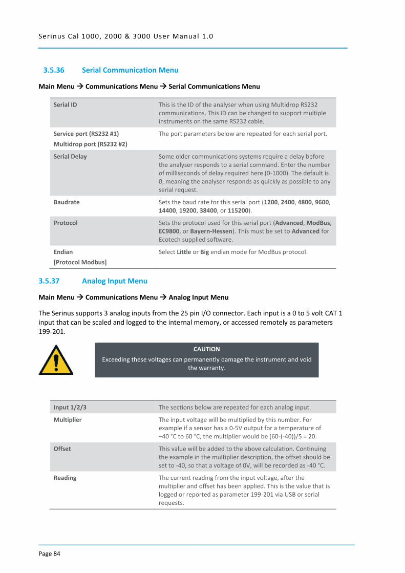
Serinus Cal 1000, 2000 & 3000 User Manual 1.0
Page 84
3.5.36 Serial Communication Menu
Main Menu Communications Menu Serial Communications Menu
Serial ID This is the ID of the analyser when using Multidrop RS232 communications. This ID can be changed to support multiple instruments on the same RS232 cable.
Service port (RS232 #1)
Multidrop port (RS232 #2)
The port parameters below are repeated for each serial port.
Serial Delay Some older communications systems require a delay before the analyser responds to a serial command. Enter the number of milliseconds of delay required here (0-1000). The default is 0, meaning the analyser responds as quickly as possible to any serial request.
Baudrate Sets the baud rate for this serial port (1200, 2400, 4800, 9600, 14400, 19200, 38400, or 115200).
Protocol Sets the protocol used for this serial port (Advanced, ModBus, EC9800, or Bayern-Hessen). This must be set to Advanced for Ecotech supplied software.
Endian
[Protocol Modbus]
Select Little or Big endian mode for ModBus protocol.
3.5.37 Analog Input Menu
Main Menu Communications Menu Analog Input Menu
The Serinus supports 3 analog inputs from the 25 pin I/O connector. Each input is a 0 to 5 volt CAT 1 input that can be scaled and logged to the internal memory, or accessed remotely as parameters 199-201.
CAUTION
Exceeding these voltages can permanently damage the instrument and void the warranty.
Input 1/2/3 The sections below are repeated for each analog input.
Multiplier The input voltage will be multiplied by this number. For example if a sensor has a 0-5V output for a temperature of –40 °C to 60 °C, the multiplier would be (60-(-40))/5 = 20.
Offset This value will be added to the above calculation. Continuing the example in the multiplier description, the offset should be set to -40, so that a voltage of 0V, will be recorded as -40 °C.
Reading The current reading from the input voltage, after the multiplier and offset has been applied. This is the value that is logged or reported as parameter 199-201 via USB or serial requests.
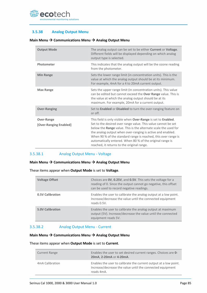
Serinus Cal 1000, 2000 & 3000 User Manual 1.0 Page 85
3.5.38 Analog Output Menu
Main Menu Communications Menu Analog Output Menu
Output Mode The analog output can be set to be either Current or Voltage. Different fields will be displayed depending on which analog output type is selected.
Photometer This indicates that the analog output will be the ozone reading from the photometer.
Min Range Sets the lower range limit (in concentration units). This is the value at which the analog output should be at its minimum. For example, 4mA for a 4 to 20mA current output.
Max Range Sets the upper range limit (in concentration units). This value can be edited but cannot exceed the Over Range value. This is the value at which the analog output should be at its maximum. For example, 20mA for a current output.
Over-Ranging Set to Enabled or Disabled to turn the over-ranging feature on or off.
Over-Range
[Over-Ranging Enabled]
This field is only visible when Over-Range is set to Enabled. Set to the desired over range value. This value cannot be set below the Range value. This is the alternate scale the used for the analog output when over-ranging is active and enabled. When 90 % of the standard range is reached, this over range is automatically entered. When 80 % of the original range is reached, it returns to the original range.
3.5.38.1 Analog Output Menu - Voltage
Main Menu Communications Menu Analog Output Menu
These items appear when Output Mode is set to Voltage.
Voltage Offset Choices are 0V, 0.25V, and 0.5V. This sets the voltage for a reading of 0. Since the output cannot go negative, this offset can be used to record negative readings.
0.5V Calibration Enables the user to calibrate the analog output at a low point. Increase/decrease the value until the connected equipment reads 0.5V.
5.0V Calibration Enables the user to calibrate the analog output at maximum output (5V). Increase/decrease the value until the connected equipment reads 5V.
3.5.38.2 Analog Output Menu - Current
Main Menu Communications Menu Analog Output Menu
These items appear when Output Mode is set to Current.
Current Range Enables the user to set desired current ranges. Choices are 0-20mA, 2-20mA or 4-20mA.
4mA Calibration Enables the user to calibrate the current output at a low point. Increase/decrease the value until the connected equipment reads 4mA.
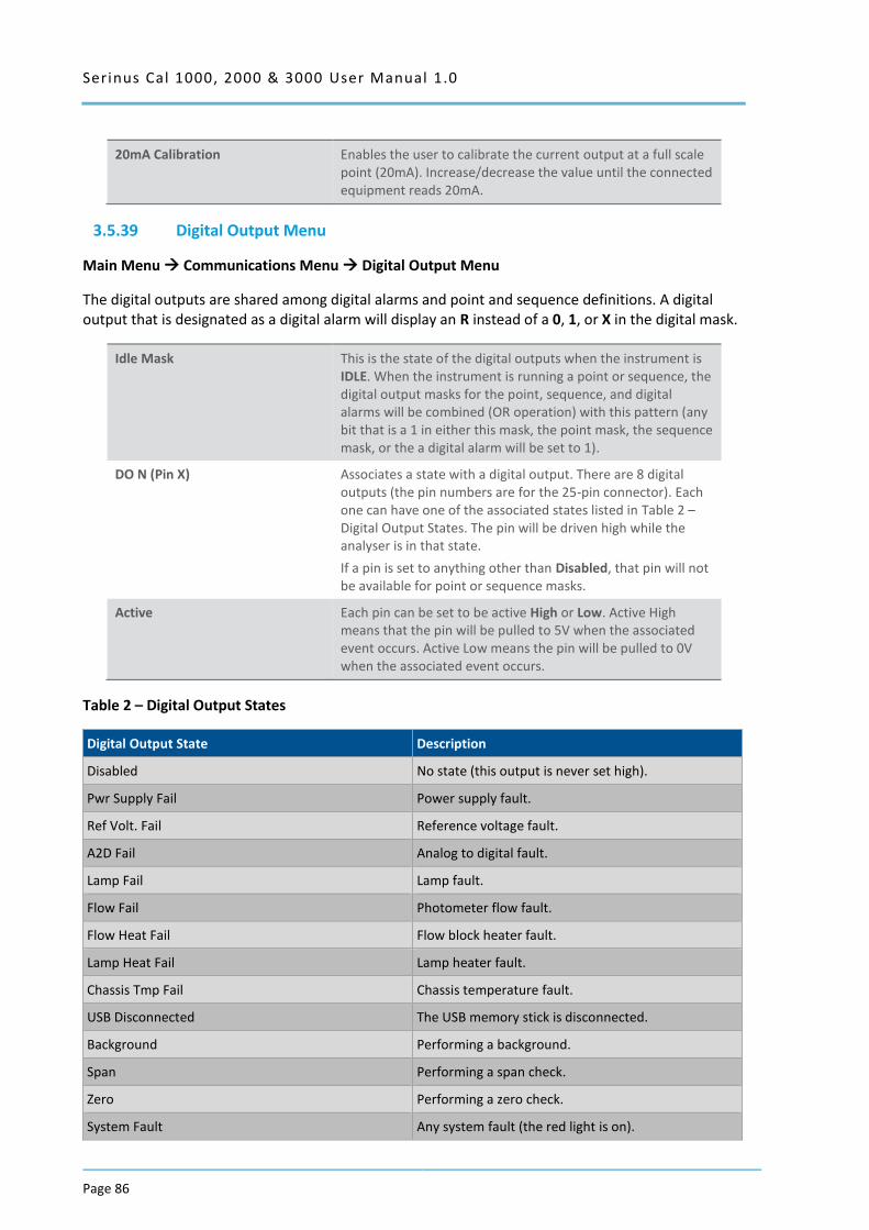
Serinus Cal 1000, 2000 & 3000 User Manual 1.0
Page 86
20mA Calibration Enables the user to calibrate the current output at a full scale point (20mA). Increase/decrease the value until the connected equipment reads 20mA.
3.5.39 Digital Output Menu
Main Menu Communications Menu Digital Output Menu
The digital outputs are shared among digital alarms and point and sequence definitions. A digital output that is designated as a digital alarm will display an R instead of a 0, 1, or X in the digital mask.
Idle Mask This is the state of the digital outputs when the instrument is IDLE. When the instrument is running a point or sequence, the digital output masks for the point, sequence, and digital alarms will be combined (OR operation) with this pattern (any bit that is a 1 in either this mask, the point mask, the sequence mask, or the a digital alarm will be set to 1).
DO N (Pin X) Associates a state with a digital output. There are 8 digital outputs (the pin numbers are for the 25-pin connector). Each one can have one of the associated states listed in Table 2 – Digital Output States. The pin will be driven high while the analyser is in that state.
If a pin is set to anything other than Disabled, that pin will not be available for point or sequence masks.
Active Each pin can be set to be active High or Low. Active High means that the pin will be pulled to 5V when the associated event occurs. Active Low means the pin will be pulled to 0V when the associated event occurs.
Table 2 – Digital Output States
Digital Output State Description
Disabled No state (this output is never set high).
Pwr Supply Fail Power supply fault.
Ref Volt. Fail Reference voltage fault.
A2D Fail Analog to digital fault.
Lamp Fail Lamp fault.
Flow Fail Photometer flow fault.
Flow Heat Fail Flow block heater fault.
Lamp Heat Fail Lamp heater fault.
Chassis Tmp Fail Chassis temperature fault.
USB Disconnected The USB memory stick is disconnected.
Background Performing a background.
Span Performing a span check.
Zero Performing a zero check.
System Fault Any system fault (the red light is on).
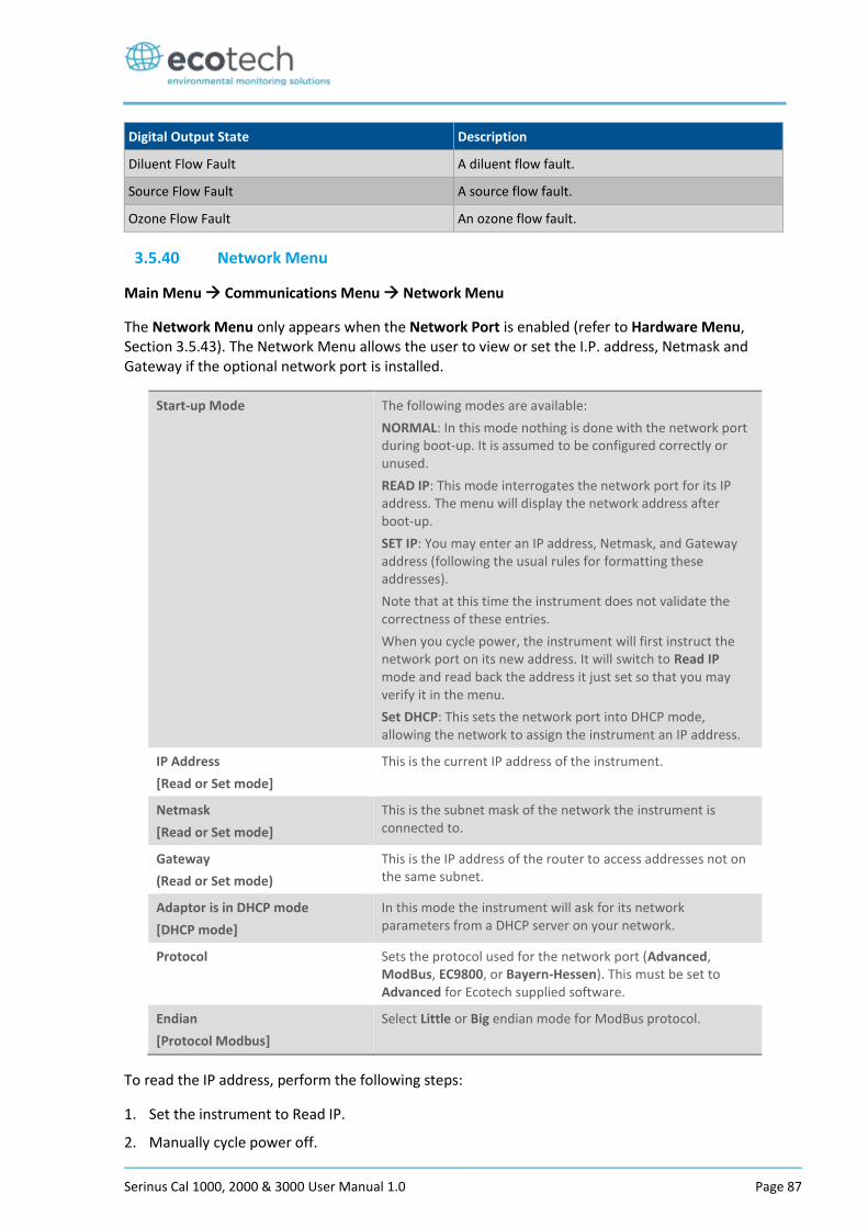
Serinus Cal 1000, 2000 & 3000 User Manual 1.0 Page 87
Digital Output State Description
Diluent Flow Fault A diluent flow fault.
Source Flow Fault A source flow fault.
Ozone Flow Fault An ozone flow fault.
3.5.40 Network Menu
Main Menu Communications Menu Network Menu
The Network Menu only appears when the Network Port is enabled (refer to Hardware Menu, Section 3.5.43). The Network Menu allows the user to view or set the I.P. address, Netmask and Gateway if the optional network port is installed.
Start-up Mode The following modes are available:
NORMAL: In this mode nothing is done with the network port during boot-up. It is assumed to be configured correctly or unused.
READ IP: This mode interrogates the network port for its IP address. The menu will display the network address after boot-up.
SET IP: You may enter an IP address, Netmask, and Gateway address (following the usual rules for formatting these addresses).
Note that at this time the instrument does not validate the correctness of these entries.
When you cycle power, the instrument will first instruct the network port on its new address. It will switch to Read IP mode and read back the address it just set so that you may verify it in the menu.
Set DHCP: This sets the network port into DHCP mode, allowing the network to assign the instrument an IP address.
IP Address
[Read or Set mode]
This is the current IP address of the instrument.
Netmask
[Read or Set mode]
This is the subnet mask of the network the instrument is connected to.
Gateway
(Read or Set mode)
This is the IP address of the router to access addresses not on the same subnet.
Adaptor is in DHCP mode
[DHCP mode]
In this mode the instrument will ask for its network parameters from a DHCP server on your network.
Protocol Sets the protocol used for the network port (Advanced, ModBus, EC9800, or Bayern-Hessen). This must be set to Advanced for Ecotech supplied software.
Endian
[Protocol Modbus]
Select Little or Big endian mode for ModBus protocol.
To read the IP address, perform the following steps:
1. Set the instrument to Read IP.
2. Manually cycle power off.
Serinus Cal 1000, 2000 & 3000 User Manual 1.0
Page 88
3. Wait 3 seconds.
4. Turn power on.
5. Read or set the IP address.
3.5.41 Bluetooth Menu
Main Menu Communications Menu Bluetooth Menu
Serinus Cal instruments support Bluetooth communication through the Serinus Remote Android Application (refer to Section 4.7).
Bluetooth This field indicates whether the instrument is remotely connected to an Android device.
Reset Bluetooth After changing the ID or PIN, it is necessary to reboot the Bluetooth module. This is done by resetting the instrument or by using this menu item to reboot only the Bluetooth.
ID This is the Bluetooth ID of the instrument. Use the keyboard to edit this field (refer to Section 3.3.1 for instructions on entering text with the numeric keypad).
The default setting is the Serinus ID/Serial Number.
Note: The word Serinus is always the first part of the name and cannot be edited.
PIN This is a passcode/pin required for the Serinus Remote Application to connect to the instrument. The default pin is 1234.
3.5.42 Advanced Menu
This menu is accessed via a different method than the other menus. From the Home Screen press the
following keys: ( . ̅)99( +SPACE
)
This menu contains technical settings, diagnostics and factory hardware installations. No items in this menu should be accessed without authorisation and supervision of qualified service personnel.
Language Select a language.
Hardware Menu Refer to Section 3.5.43.
Service Displays When set to On, new items appear on many different menus. These fields are for diagnostic and service personnel only. Default is Off.
Next Service Due Enter the next service due date.
Jump to Next State
[Serinus Cal 3000]
Move to the next mode (for example, from fill to measure). This command is most commonly used to force an instrument out of warm-up early.
Parameter Display Menu Refer to Section 3.5.45.
Reset to Factory Defaults Reset the configuration to factory defaults. This will erase all calibrations and user configuration information.
Rebuild Index If a data log becomes corrupted it may be possible to restore It by rebuilding its index file. This command will ask you to
Serinus Cal 1000, 2000 & 3000 User Manual 1.0 Page 89
specify a month and will rebuild the index for that month. This operation can take many minutes and it should not be interrupted. While the file is rebuilding any data logging will be suspended.
3.5.43 Hardware Menu
Advanced Menu Hardware Menu
This menu contains factory hardware installations. If you reset to factory defaults you may need to revisit this menu to re-install optional features.
Variant Select the instrument model. Normally this only needs to be reset when the configuration is corrupted. The selections available will depend on licensing. It is not recommended to run an instrument with firmware set to an incorrect model.
Front Panel Style Choosing the incorrect front panel will result in the traffic lights behaving inconsistently. Default is Aluminium.
Network Port The instrument has a network port. Default is Disabled.
Orifice Size
[Serinus Cal 3000]
Specify the input orifice for the calibrator. Note that unlike the Serinus line of analysers, the Serinus Cal 3000 uses both an orifice and an internal pump. Default is 0.3.
Warm O3 Gen
[Serinus Cal 2000 and 3000]
If Enabled, keeps the O3 Gen lamp at a minimum voltage even when not being used. Keeping the lamp warm will improve ozone response time. Default is Disabled.
Please note that during an Ozone Zero point (when the instrument has been instructed to produce 0.0 ozone concentration) the lamp will be turned completely off, regardless of this setting.
MFC Installation Menu Refer to Section 3.5.44.
Dual Diluent Valve If Enabled, allows the calibrator to select between two diluents. Default is Disabled.
Optional Source If Enabled, allows the four additional input valves V5-V8. Default is Disabled.
3.5.44 MFC Installation Menu
Advanced Menu Hardware Menu MFC Installation Menu
Select an MFC by capacity (i.e. 50 SCCM) from the list of supported capacities. When an MFC is selected, the polynomials for its calibration will be displayed.
MFC Source This is the primary source MFC.
MFC Opt Source This is the optional source MFC. The microprocessor will select the correct MFC to use based on the concentration requested and the capacity of the MFC.
MFC Diluent The primary diluent MFC.
MFC Opt Diluent Optional diluent MFC. Will be used when the primary MFC cannot accurately supply the requested flow.
Poly A Co-efficient for MFC calibration.
Serinus Cal 1000, 2000 & 3000 User Manual 1.0
Page 90
Poly B Co-efficient for MFC calibration.
Poly C Co-efficient for MFC calibration.
3.5.45 Parameter Display Menu
Advanced Menu Parameter Display Menu
Used to display a parameter in real-time on the screen (refer to Table 13 for a full list of parameters).
Data Parameter Enter the Advanced Command parameter number.
Name Displays the name of the selected parameter.
Value Displays the current value of the selected parameter.
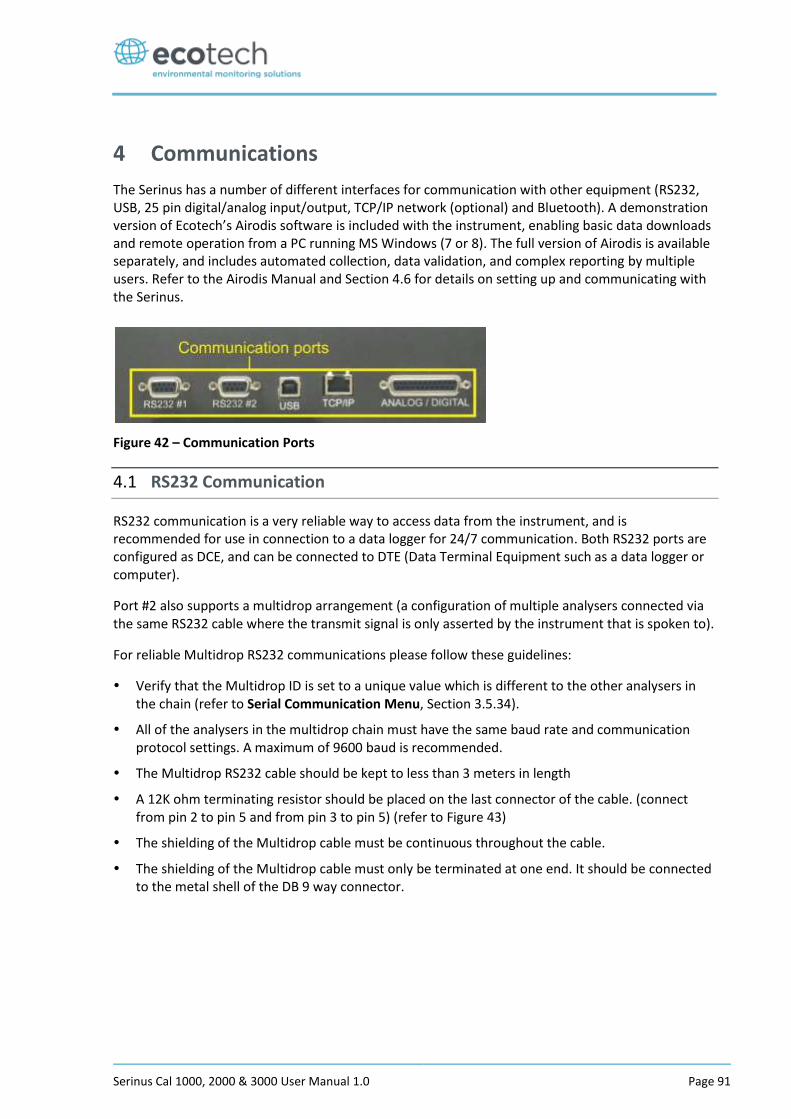
Serinus Cal 1000, 2000 & 3000 User Manual 1.0 Page 91
4 Communications
The Serinus has a number of different interfaces for communication with other equipment (RS232, USB, 25 pin digital/analog input/output, TCP/IP network (optional) and Bluetooth). A demonstration version of Ecotech’s Airodis software is included with the instrument, enabling basic data downloads and remote operation from a PC running MS Windows (7 or 8). The full version of Airodis is available separately, and includes automated collection, data validation, and complex reporting by multiple users. Refer to the Airodis Manual and Section 4.6 for details on setting up and communicating with the Serinus.
Figure 42 – Communication Ports
4.1 RS232 Communication
RS232 communication is a very reliable way to access data from the instrument, and is recommended for use in connection to a data logger for 24/7 communication. Both RS232 ports are configured as DCE, and can be connected to DTE (Data Terminal Equipment such as a data logger or computer).
Port #2 also supports a multidrop arrangement (a configuration of multiple analysers connected via the same RS232 cable where the transmit signal is only asserted by the instrument that is spoken to).
For reliable Multidrop RS232 communications please follow these guidelines:
Verify that the Multidrop ID is set to a unique value which is different to the other analysers in the chain (refer to Serial Communication Menu, Section 3.5.34).
All of the analysers in the multidrop chain must have the same baud rate and communication protocol settings. A maximum of 9600 baud is recommended.
The Multidrop RS232 cable should be kept to less than 3 meters in length
A 12K ohm terminating resistor should be placed on the last connector of the cable. (connect from pin 2 to pin 5 and from pin 3 to pin 5) (refer to Figure 43)
The shielding of the Multidrop cable must be continuous throughout the cable.
The shielding of the Multidrop cable must only be terminated at one end. It should be connected to the metal shell of the DB 9 way connector.

Serinus Cal 1000, 2000 & 3000 User Manual 1.0
Page 92
Figure 43 – Multidrop RS232 Cable Example
4.2 USB Communication
This is ideal for irregular connection to a laptop running Ecotech’s Airodis software to download logged data and remotely control the instrument. Due to the nature of USB, this is a less reliable permanent connection as external electrical noise can cause USB disconnection errors on a data logger.
Please note that only the Advanced protocol (refer to Section 0) is supported for USB communication.
4.3 TCP/IP Network Communication (optional)
Instruments with the optional network port installed can be accessed using a TCP/IP connection. Figure 45 shows examples of some possible configurations for remote access.
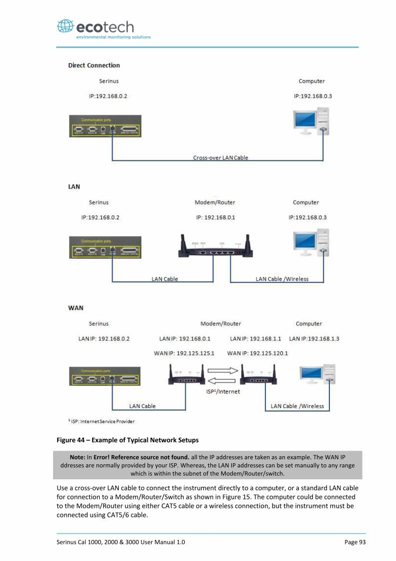
Serinus Cal 1000, 2000 & 3000 User Manual 1.0 Page 93
Figure 44 – Example of Typical Network Setups
Note: In Error! Reference source not found. all the IP addresses are taken as an example. The WAN IP ddresses are normally provided by your ISP. Whereas, the LAN IP addresses can be set manually to any range
which is within the subnet of the Modem/Router/switch.
Use a cross-over LAN cable to connect the instrument directly to a computer, or a standard LAN cable for connection to a Modem/Router/Switch as shown in Figure 15. The computer could be connected to the Modem/Router using either CAT5 cable or a wireless connection, but the instrument must be connected using CAT5/6 cable.
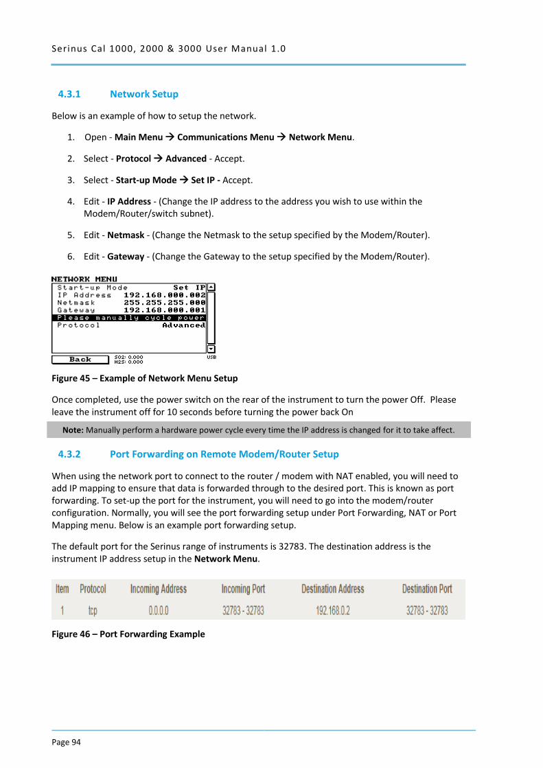
Serinus Cal 1000, 2000 & 3000 User Manual 1.0
Page 94
4.3.1 Network Setup
Below is an example of how to setup the network.
1. Open - Main Menu Communications Menu Network Menu.
2. Select - Protocol Advanced - Accept.
3. Select - Start-up Mode Set IP - Accept.
4. Edit - IP Address - (Change the IP address to the address you wish to use within the Modem/Router/switch subnet).
5. Edit - Netmask - (Change the Netmask to the setup specified by the Modem/Router).
6. Edit - Gateway - (Change the Gateway to the setup specified by the Modem/Router).
Figure 45 – Example of Network Menu Setup
Once completed, use the power switch on the rear of the instrument to turn the power Off. Please leave the instrument off for 10 seconds before turning the power back On
Note: Manually perform a hardware power cycle every time the IP address is changed for it to take affect.
4.3.2 Port Forwarding on Remote Modem/Router Setup
When using the network port to connect to the router / modem with NAT enabled, you will need to add IP mapping to ensure that data is forwarded through to the desired port. This is known as port forwarding. To set-up the port for the instrument, you will need to go into the modem/router configuration. Normally, you will see the port forwarding setup under Port Forwarding, NAT or Port Mapping menu. Below is an example port forwarding setup.
The default port for the Serinus range of instruments is 32783. The destination address is the instrument IP address setup in the Network Menu.
Figure 46 – Port Forwarding Example
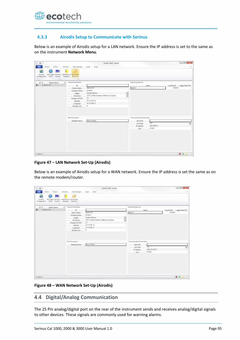
Serinus Cal 1000, 2000 & 3000 User Manual 1.0 Page 95
4.3.3 Airodis Setup to Communicate with Serinus
Below is an example of Airodis setup for a LAN network. Ensure the IP address is set to the same as on the instrument Network Menu.
Figure 47 – LAN Network Set-Up (Airodis)
Below is an example of Airodis setup for a WAN network. Ensure the IP address is set the same as on the remote modem/router.
Figure 48 – WAN Network Set-Up (Airodis)
4.4 Digital/Analog Communication
The 25 Pin analog/digital port on the rear of the instrument sends and receives analog/digital signals to other devices. These signals are commonly used for warning alarms.
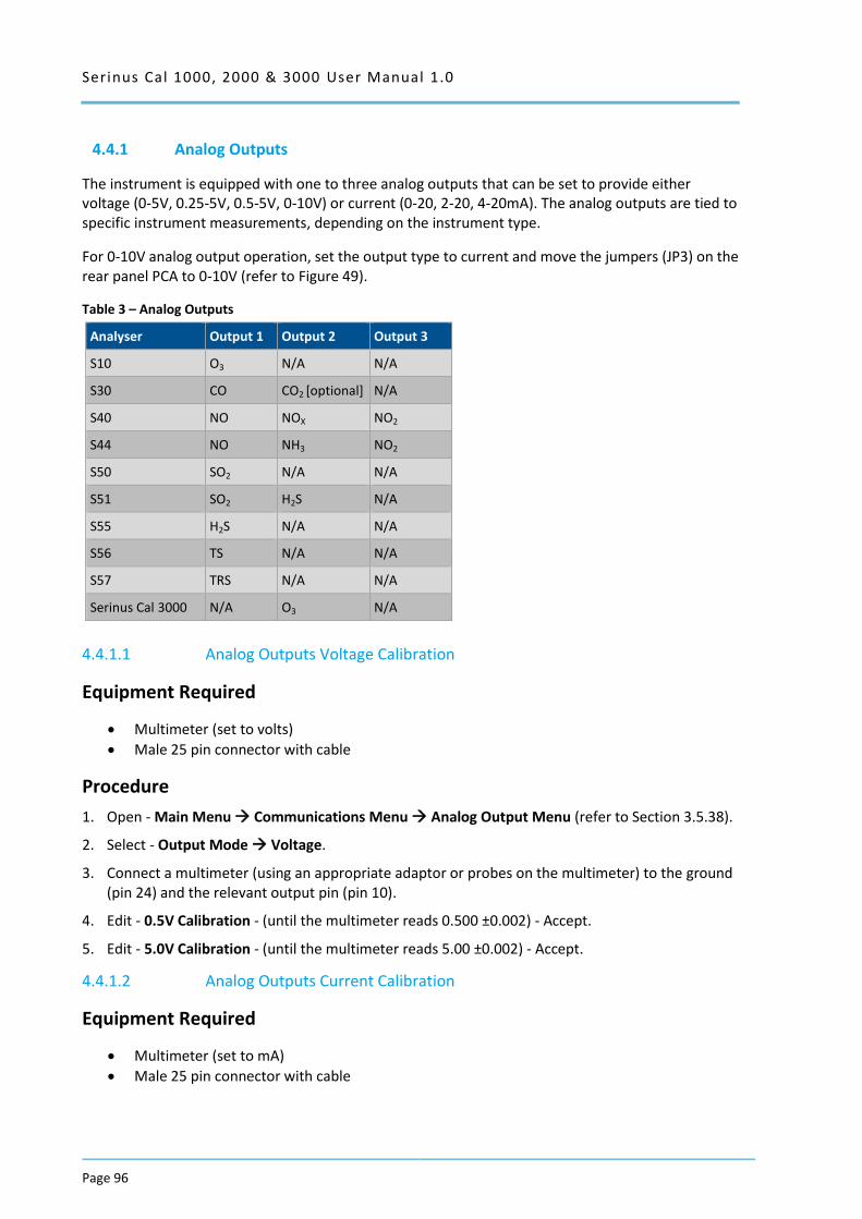
Serinus Cal 1000, 2000 & 3000 User Manual 1.0
Page 96
4.4.1 Analog Outputs
The instrument is equipped with one to three analog outputs that can be set to provide either voltage (0-5V, 0.25-5V, 0.5-5V, 0-10V) or current (0-20, 2-20, 4-20mA). The analog outputs are tied to specific instrument measurements, depending on the instrument type.
For 0-10V analog output operation, set the output type to current and move the jumpers (JP3) on the rear panel PCA to 0-10V (refer to Figure 49).
Table 3 – Analog Outputs
Analyser Output 1 Output 2 Output 3
S10 O3 N/A N/A
S30 CO CO2 [optional] N/A
S40 NO NOX NO2
S44 NO NH3 NO2
S50 SO2 N/A N/A
S51 SO2 H2S N/A
S55 H2S N/A N/A
S56 TS N/A N/A
S57 TRS N/A N/A
Serinus Cal 3000 N/A O3 N/A
4.4.1.1 Analog Outputs Voltage Calibration
Equipment Required
Multimeter (set to volts)
Male 25 pin connector with cable
Procedure
1. Open - Main Menu Communications Menu Analog Output Menu (refer to Section 3.5.38).
2. Select - Output Mode Voltage.
3. Connect a multimeter (using an appropriate adaptor or probes on the multimeter) to the ground (pin 24) and the relevant output pin (pin 10).
4. Edit - 0.5V Calibration - (until the multimeter reads 0.500 ±0.002) - Accept.
5. Edit - 5.0V Calibration - (until the multimeter reads 5.00 ±0.002) - Accept.
4.4.1.2 Analog Outputs Current Calibration
Equipment Required
Multimeter (set to mA)
Male 25 pin connector with cable
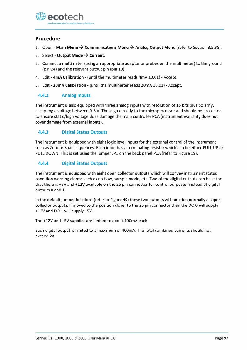
Serinus Cal 1000, 2000 & 3000 User Manual 1.0 Page 97
Procedure
1. Open - Main Menu Communications Menu Analog Output Menu (refer to Section 3.5.38).
2. Select - Output Mode Current.
3. Connect a multimeter (using an appropriate adaptor or probes on the multimeter) to the ground (pin 24) and the relevant output pin (pin 10).
4. Edit - 4mA Calibration - (until the multimeter reads 4mA ±0.01) - Accept.
5. Edit - 20mA Calibration - (until the multimeter reads 20mA ±0.01) - Accept.
4.4.2 Analog Inputs
The instrument is also equipped with three analog inputs with resolution of 15 bits plus polarity, accepting a voltage between 0-5 V. These go directly to the microprocessor and should be protected to ensure static/high voltage does damage the main controller PCA (instrument warranty does not cover damage from external inputs).
4.4.3 Digital Status Outputs
The instrument is equipped with eight logic level inputs for the external control of the instrument such as Zero or Span sequences. Each input has a terminating resistor which can be either PULL UP or PULL DOWN. This is set using the jumper JP1 on the back panel PCA (refer to Figure 19).
4.4.4 Digital Status Outputs
The instrument is equipped with eight open collector outputs which will convey instrument status condition warning alarms such as no flow, sample mode, etc. Two of the digital outputs can be set so that there is +5V and +12V available on the 25 pin connector for control purposes, instead of digital outputs 0 and 1.
In the default jumper locations (refer to Figure 49) these two outputs will function normally as open collector outputs. If moved to the position closer to the 25 pin connector then the DO 0 will supply +12V and DO 1 will supply +5V.
The +12V and +5V supplies are limited to about 100mA each.
Each digital output is limited to a maximum of 400mA. The total combined currents should not exceed 2A.
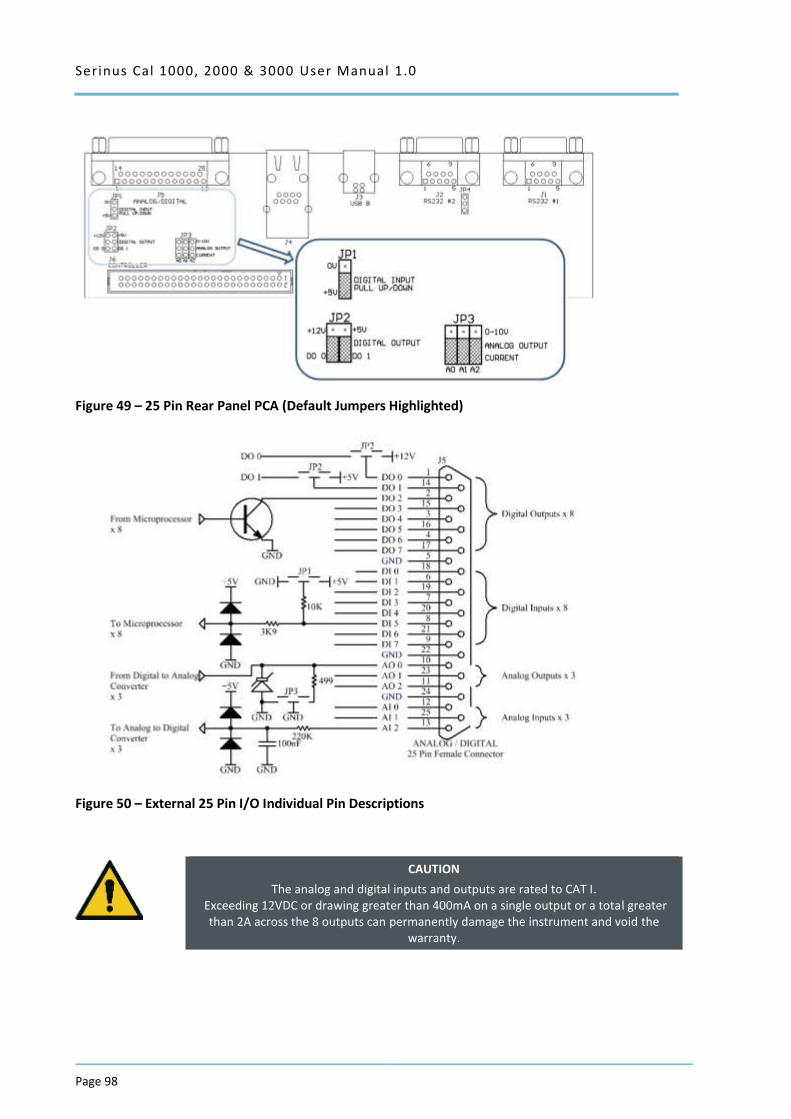
Serinus Cal 1000, 2000 & 3000 User Manual 1.0
Page 98
Figure 49 – 25 Pin Rear Panel PCA (Default Jumpers Highlighted)
Figure 50 – External 25 Pin I/O Individual Pin Descriptions
CAUTION
The analog and digital inputs and outputs are rated to CAT I. Exceeding 12VDC or drawing greater than 400mA on a single output or a total greater
than 2A across the 8 outputs can permanently damage the instrument and void the warranty.
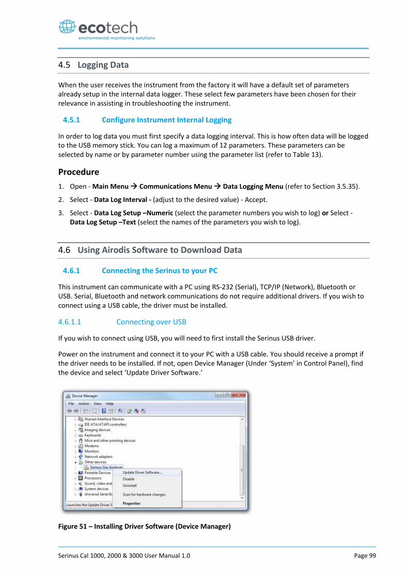
Serinus Cal 1000, 2000 & 3000 User Manual 1.0 Page 99
4.5 Logging Data
When the user receives the instrument from the factory it will have a default set of parameters already setup in the internal data logger. These select few parameters have been chosen for their relevance in assisting in troubleshooting the instrument.
4.5.1 Configure Instrument Internal Logging
In order to log data you must first specify a data logging interval. This is how often data will be logged to the USB memory stick. You can log a maximum of 12 parameters. These parameters can be selected by name or by parameter number using the parameter list (refer to Table 13).
Procedure
1. Open - Main Menu Communications Menu Data Logging Menu (refer to Section 3.5.35).
2. Select - Data Log Interval - (adjust to the desired value) - Accept.
3. Select - Data Log Setup –Numeric (select the parameter numbers you wish to log) or Select - Data Log Setup –Text (select the names of the parameters you wish to log).
4.6 Using Airodis Software to Download Data
4.6.1 Connecting the Serinus to your PC
This instrument can communicate with a PC using RS-232 (Serial), TCP/IP (Network), Bluetooth or USB. Serial, Bluetooth and network communications do not require additional drivers. If you wish to connect using a USB cable, the driver must be installed.
4.6.1.1 Connecting over USB
If you wish to connect using USB, you will need to first install the Serinus USB driver.
Power on the instrument and connect it to your PC with a USB cable. You should receive a prompt if the driver needs to be installed. If not, open Device Manager (Under ‘System’ in Control Panel), find the device and select ‘Update Driver Software.’
Figure 51 – Installing Driver Software (Device Manager)
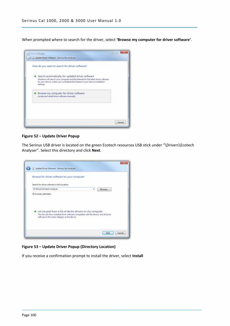
Serinus Cal 1000, 2000 & 3000 User Manual 1.0
Page 100
When prompted where to search for the driver, select ‘Browse my computer for driver software’.
Figure 52 – Update Driver Popup
The Serinus USB driver is located on the green Ecotech resources USB stick under “\Drivers\Ecotech Analyser”. Select this directory and click Next.
Figure 53 – Update Driver Popup (Directory Location)
If you receive a confirmation prompt to install the driver, select Install
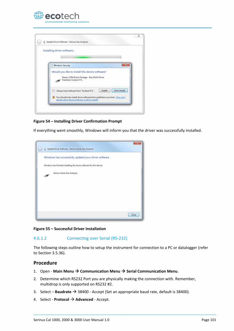
Serinus Cal 1000, 2000 & 3000 User Manual 1.0 Page 101
Figure 54 – Installing Driver Confirmation Prompt
If everything went smoothly, Windows will inform you that the driver was successfully installed.
Figure 55 – Successful Driver Installation
4.6.1.2 Connecting over Serial (RS-232)
The following steps outline how to setup the instrument for connection to a PC or datalogger (refer to Section 3.5.36).
Procedure
1. Open - Main Menu Communication Menu Serial Communication Menu.
2. Determine which RS232 Port you are physically making the connection with. Remember, multidrop is only supported on RS232 #2.
3. Select – Baudrate 38400 - Accept (Set an appropriate baud rate, default is 38400).
4. Select - Protocol Advanced - Accept.
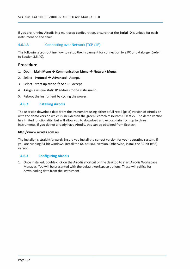
Serinus Cal 1000, 2000 & 3000 User Manual 1.0
Page 102
If you are running Airodis in a multidrop configuration, ensure that the Serial ID is unique for each instrument on the chain.
4.6.1.3 Connecting over Network (TCP / IP)
The following steps outline how to setup the instrument for connection to a PC or datalogger (refer to Section 3.5.40).
Procedure
1. Open - Main Menu Communication Menu Network Menu.
2. Select - Protocol Advanced - Accept.
3. Select - Start-up Mode Set IP - Accept.
4. Assign a unique static IP address to the instrument.
5. Reboot the instrument by cycling the power.
4.6.2 Installing Airodis
The user can download data from the instrument using either a full retail (paid) version of Airodis or with the demo version which is included on the green Ecotech resources USB stick. The demo version has limited functionality, but will allow you to download and export data from up to three instruments. If you do not already have Airodis, this can be obtained from Ecotech:
http://www.airodis.com.au
The installer is straightforward: Ensure you install the correct version for your operating system. If you are running 64-bit windows, install the 64-bit (x64) version. Otherwise, install the 32-bit (x86) version.
4.6.3 Configuring Airodis
1. Once installed, double click on the Airodis shortcut on the desktop to start Airodis Workspace Manager. You will be presented with the default workspace options. These will suffice for downloading data from the instrument.
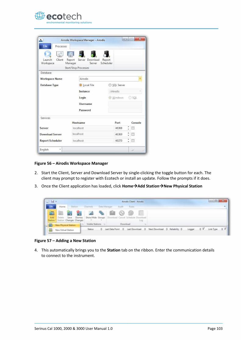
Serinus Cal 1000, 2000 & 3000 User Manual 1.0 Page 103
Figure 56 – Airodis Workspace Manager
2. Start the Client, Server and Download Server by single-clicking the toggle button for each. The client may prompt to register with Ecotech or install an update. Follow the prompts if it does.
3. Once the Client application has loaded, click HomeAdd StationNew Physical Station
Figure 57 – Adding a New Station
4. This automatically brings you to the Station tab on the ribbon. Enter the communication details to connect to the instrument.
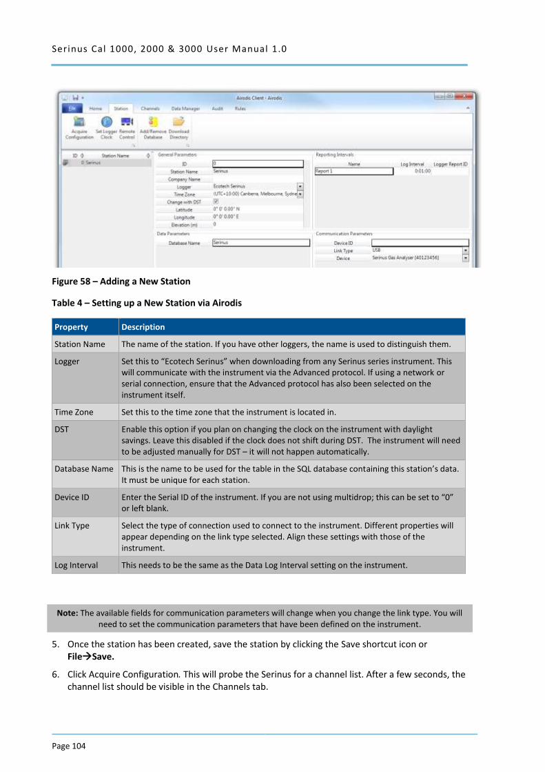
Serinus Cal 1000, 2000 & 3000 User Manual 1.0
Page 104
Figure 58 – Adding a New Station
Table 4 – Setting up a New Station via Airodis
Property Description
Station Name The name of the station. If you have other loggers, the name is used to distinguish them.
Logger Set this to “Ecotech Serinus” when downloading from any Serinus series instrument. This will communicate with the instrument via the Advanced protocol. If using a network or serial connection, ensure that the Advanced protocol has also been selected on the instrument itself.
Time Zone Set this to the time zone that the instrument is located in.
DST Enable this option if you plan on changing the clock on the instrument with daylight savings. Leave this disabled if the clock does not shift during DST. The instrument will need to be adjusted manually for DST – it will not happen automatically.
Database Name This is the name to be used for the table in the SQL database containing this station’s data. It must be unique for each station.
Device ID Enter the Serial ID of the instrument. If you are not using multidrop; this can be set to “0” or left blank.
Link Type Select the type of connection used to connect to the instrument. Different properties will appear depending on the link type selected. Align these settings with those of the instrument.
Log Interval This needs to be the same as the Data Log Interval setting on the instrument.
Note: The available fields for communication parameters will change when you change the link type. You will need to set the communication parameters that have been defined on the instrument.
5. Once the station has been created, save the station by clicking the Save shortcut icon or FileSave.
6. Click Acquire Configuration. This will probe the Serinus for a channel list. After a few seconds, the channel list should be visible in the Channels tab.
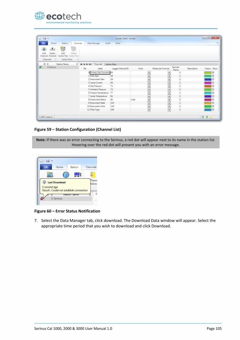
Serinus Cal 1000, 2000 & 3000 User Manual 1.0 Page 105
Figure 59 – Station Configuration (Channel List)
Note: If there was an error connecting to the Serinus, a red dot will appear next to its name in the station list. Hovering over the red dot will present you with an error message.
Figure 60 – Error Status Notification
7. Select the Data Manager tab, click download. The Download Data window will appear. Select the appropriate time period that you wish to download and click Download.
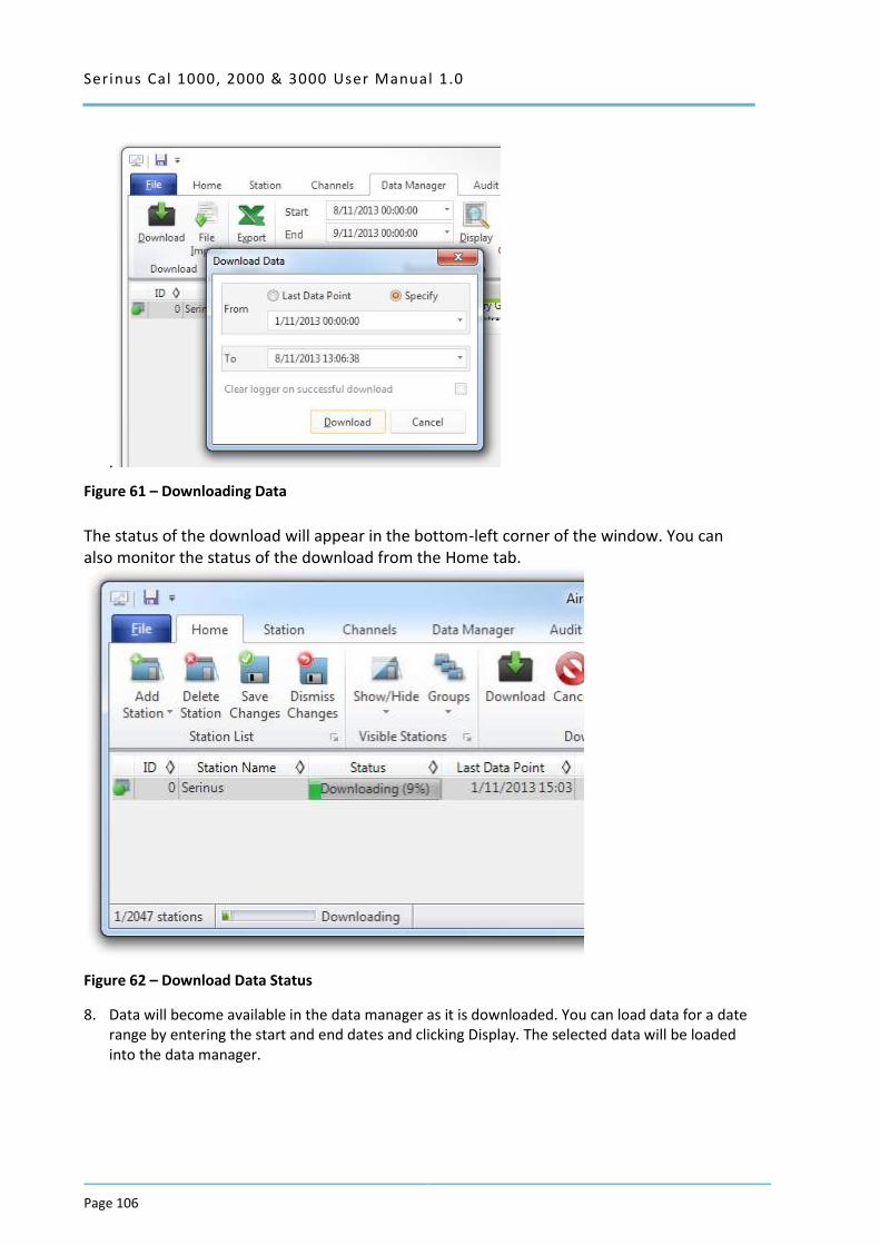
Serinus Cal 1000, 2000 & 3000 User Manual 1.0
Page 106
.
Figure 61 – Downloading Data
The status of the download will appear in the bottom-left corner of the window. You can also monitor the status of the download from the Home tab.
Figure 62 – Download Data Status
8. Data will become available in the data manager as it is downloaded. You can load data for a date range by entering the start and end dates and clicking Display. The selected data will be loaded into the data manager.
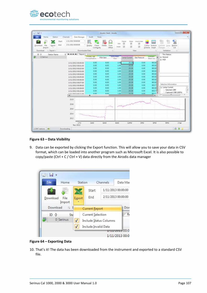
Serinus Cal 1000, 2000 & 3000 User Manual 1.0 Page 107
Figure 63 – Data Visibility
9. Data can be exported by clicking the Export function. This will allow you to save your data in CSV format, which can be loaded into another program such as Microsoft Excel. It is also possible to copy/paste (Ctrl + C / Ctrl + V) data directly from the Airodis data manager
Figure 64 – Exporting Data
10. That’s it! The data has been downloaded from the instrument and exported to a standard CSV file.
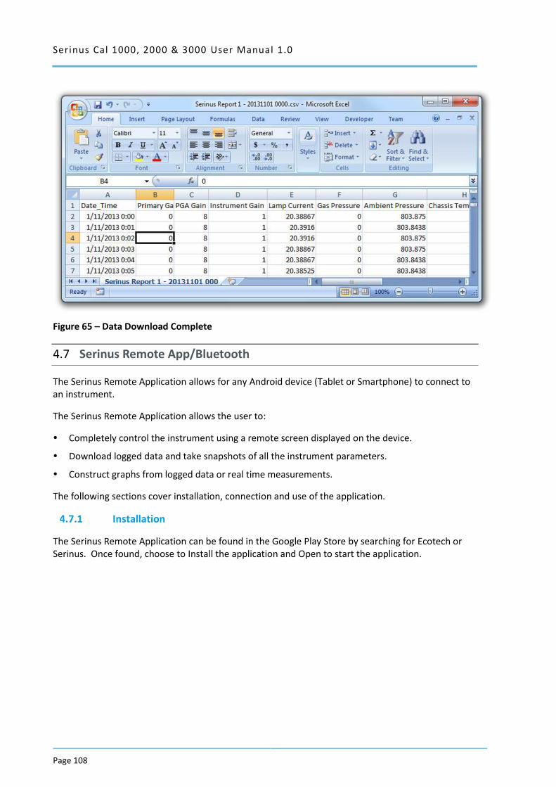
Serinus Cal 1000, 2000 & 3000 User Manual 1.0
Page 108
Figure 65 – Data Download Complete
4.7 Serinus Remote App/Bluetooth
The Serinus Remote Application allows for any Android device (Tablet or Smartphone) to connect to an instrument.
The Serinus Remote Application allows the user to:
Completely control the instrument using a remote screen displayed on the device.
Download logged data and take snapshots of all the instrument parameters.
Construct graphs from logged data or real time measurements.
The following sections cover installation, connection and use of the application.
4.7.1 Installation
The Serinus Remote Application can be found in the Google Play Store by searching for Ecotech or Serinus. Once found, choose to Install the application and Open to start the application.
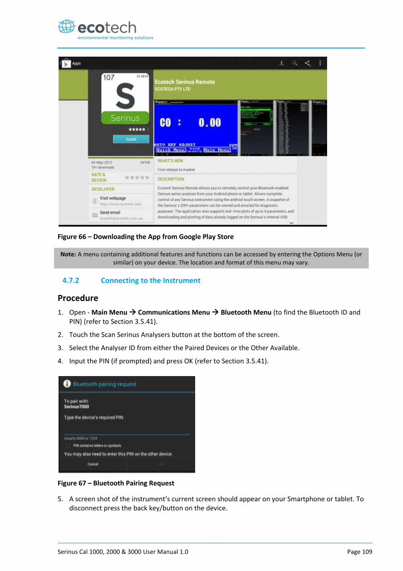
Serinus Cal 1000, 2000 & 3000 User Manual 1.0 Page 109
Figure 66 – Downloading the App from Google Play Store
Note: A menu containing additional features and functions can be accessed by entering the Options Menu (or similar) on your device. The location and format of this menu may vary.
4.7.2 Connecting to the Instrument
Procedure
1. Open - Main Menu Communications Menu Bluetooth Menu (to find the Bluetooth ID and PIN) (refer to Section 3.5.41).
2. Touch the Scan Serinus Analysers button at the bottom of the screen.
3. Select the Analyser ID from either the Paired Devices or the Other Available.
4. Input the PIN (if prompted) and press OK (refer to Section 3.5.41).
Figure 67 – Bluetooth Pairing Request
5. A screen shot of the instrument’s current screen should appear on your Smartphone or tablet. To disconnect press the back key/button on the device.
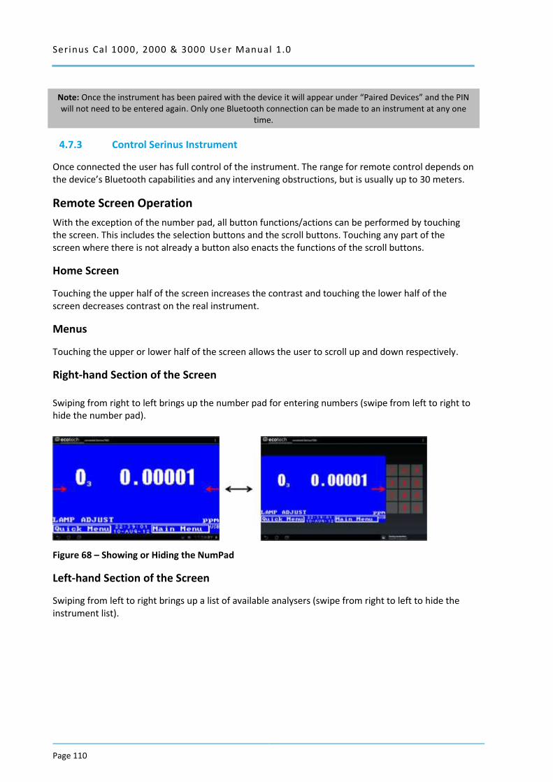
Serinus Cal 1000, 2000 & 3000 User Manual 1.0
Page 110
Note: Once the instrument has been paired with the device it will appear under “Paired Devices” and the PIN will not need to be entered again. Only one Bluetooth connection can be made to an instrument at any one
time.
4.7.3 Control Serinus Instrument
Once connected the user has full control of the instrument. The range for remote control depends on the device’s Bluetooth capabilities and any intervening obstructions, but is usually up to 30 meters.
Remote Screen Operation
With the exception of the number pad, all button functions/actions can be performed by touching the screen. This includes the selection buttons and the scroll buttons. Touching any part of the screen where there is not already a button also enacts the functions of the scroll buttons.
Home Screen
Touching the upper half of the screen increases the contrast and touching the lower half of the screen decreases contrast on the real instrument.
Menus
Touching the upper or lower half of the screen allows the user to scroll up and down respectively.
Right-hand Section of the Screen
Swiping from right to left brings up the number pad for entering numbers (swipe from left to right to hide the number pad).
Figure 68 – Showing or Hiding the NumPad
Left-hand Section of the Screen
Swiping from left to right brings up a list of available analysers (swipe from right to left to hide the instrument list).
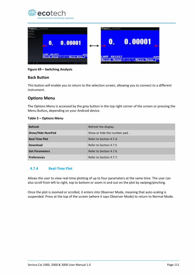
Serinus Cal 1000, 2000 & 3000 User Manual 1.0 Page 111
Figure 69 – Switching Analysis
Back Button
This button will enable you to return to the selection screen, allowing you to connect to a different instrument.
Options Menu
The Options Menu is accessed by the grey button in the top right corner of the screen or pressing the Menu Button, depending on your Android device.
Table 5 – Options Menu
Refresh Refresh the display.
Show/Hide NumPad Show or hide the number pad.
Real Time Plot Refer to Section 4.7.4. Download Refer to Section 4.7.5
Get Parameters Refer to Section 4.7.6.
Preferences Refer to Section 4.7.7.
4.7.4 Real-Time Plot
Allows the user to view real-time plotting of up to four parameters at the same time. The user can also scroll from left to right, top to bottom or zoom in and out on the plot by swiping/pinching.
Once the plot is zoomed or scrolled, it enters into Observer Mode, meaning that auto-scaling is suspended. Press at the top of the screen (where it says Observer Mode) to return to Normal Mode.
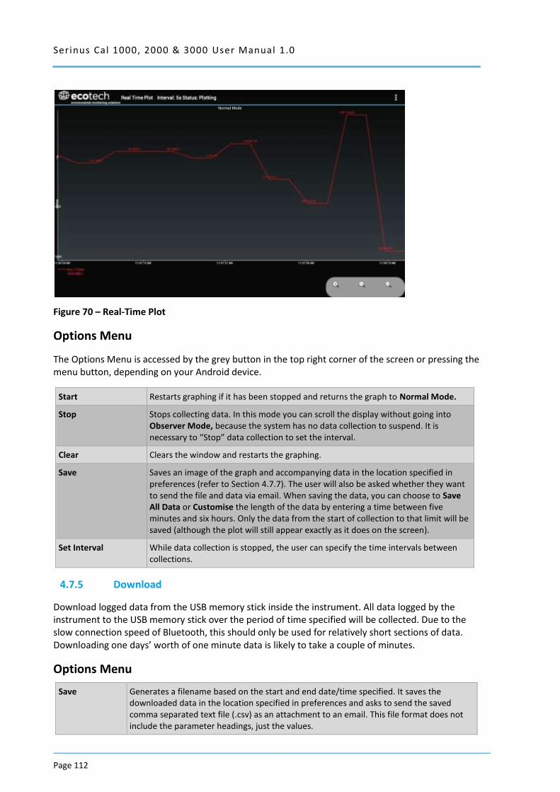
Serinus Cal 1000, 2000 & 3000 User Manual 1.0
Page 112
Figure 70 – Real-Time Plot
Options Menu
The Options Menu is accessed by the grey button in the top right corner of the screen or pressing the menu button, depending on your Android device.
Start Restarts graphing if it has been stopped and returns the graph to Normal Mode.
Stop Stops collecting data. In this mode you can scroll the display without going into Observer Mode, because the system has no data collection to suspend. It is necessary to “Stop” data collection to set the interval.
Clear Clears the window and restarts the graphing. Save Saves an image of the graph and accompanying data in the location specified in
preferences (refer to Section 4.7.7). The user will also be asked whether they want to send the file and data via email. When saving the data, you can choose to Save All Data or Customise the length of the data by entering a time between five minutes and six hours. Only the data from the start of collection to that limit will be saved (although the plot will still appear exactly as it does on the screen).
Set Interval While data collection is stopped, the user can specify the time intervals between collections.
4.7.5 Download
Download logged data from the USB memory stick inside the instrument. All data logged by the instrument to the USB memory stick over the period of time specified will be collected. Due to the slow connection speed of Bluetooth, this should only be used for relatively short sections of data. Downloading one days’ worth of one minute data is likely to take a couple of minutes.
Options Menu
Save Generates a filename based on the start and end date/time specified. It saves the downloaded data in the location specified in preferences and asks to send the saved comma separated text file (.csv) as an attachment to an email. This file format does not include the parameter headings, just the values.
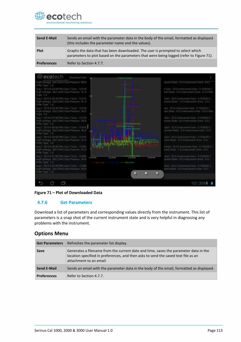
Serinus Cal 1000, 2000 & 3000 User Manual 1.0 Page 113
Send E-Mail Sends an email with the parameter data in the body of the email, formatted as displayed (this includes the parameter name and the values).
Plot Graphs the data that has been downloaded. The user is prompted to select which parameters to plot based on the parameters that were being logged (refer to Figure 71).
Preferences Refer to Section 4.7.7.
Figure 71 – Plot of Downloaded Data
4.7.6 Get Parameters
Download a list of parameters and corresponding values directly from the instrument. This list of parameters is a snap shot of the current instrument state and is very helpful in diagnosing any problems with the instrument.
Options Menu
Get Parameters Refreshes the parameter list display.
Save Generates a filename from the current date and time, saves the parameter data in the location specified in preferences, and then asks to send the saved text file as an attachment to an email.
Send E-Mail Sends an email with the parameter data in the body of the email, formatted as displayed.
Preferences Refer to Section 4.7.7.

Serinus Cal 1000, 2000 & 3000 User Manual 1.0
Page 114
4.7.7 Preferences
The Preferences Menu allows the operator to adjust the directory settings, logged data format and the colour scheme settings. It can be accessed through the Options Menu in most windows.
Directory Settings
The operator can specify/select where to save the parameter lists, logged data and real time plots.
Figure 72 – Directory Settings
Logs Format
When downloading logged data, the parameters can be displayed on one line or each parameter on a separate line.
Figure 73 – Logs Format
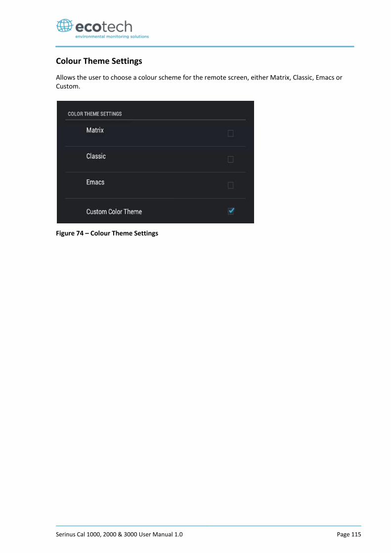
Serinus Cal 1000, 2000 & 3000 User Manual 1.0 Page 115
Colour Theme Settings
Allows the user to choose a colour scheme for the remote screen, either Matrix, Classic, Emacs or Custom.
Figure 74 – Colour Theme Settings

Serinus Cal 1000, 2000 & 3000 User Manual 1.0
Page 116
This page is intentionally blank.
Serinus Cal 1000, 2000 & 3000 User Manual 1.0 Page 117
5 Calibration
The following sections will cover how to calibrate the MFC’s, ozone flow, pressure, ozone generator and photometer.
5.1 MFC Calibration
Serinus Cal 1000, 2000 and 3000
It is necessary occasionally to re-calibrate the mass flow controllers within the Serinus Cal. This is required for all Serinus Cal variants.
In order to perform this task you will require a flow device/s having an accuracy of equal to or better than 1% of the device under test and must be currently certified.
Equipment Required
A certified mass flow measurement device OR
A certified volumetric flow measurement device/s in conjunction with a certified temperature probe and barometer.
Note: The measurement devices range must match the range of the Serinus Cal MFC you are calibrating. Typical setup is a Diluent MFC Range 0 – 10 slpm and a Source Gas MFC Range 0 – 50 sccm.
Procedure
Note: You can either, connect another MFM (Mass Flow Meter) device to the Serinus Cal set to 0 Deg C and 1013.25 mbar, OR if the measurement device is volumetric, measure the temperature and pressure of the gas stream to calculate the volumetric flow into mass flow. It is important to have stable ambient conditions when
performing this calibration to ensure accurate and consistent results.
CAUTION
It is recommended that exhaust air is not expelled into a shelter/room inhabited by people. It should be expelled into the external air and away from the
sample inlet. Connecting diluent AIR to a span port (via a T-Piece) reduces the risk of exposure to hazardous source gases.
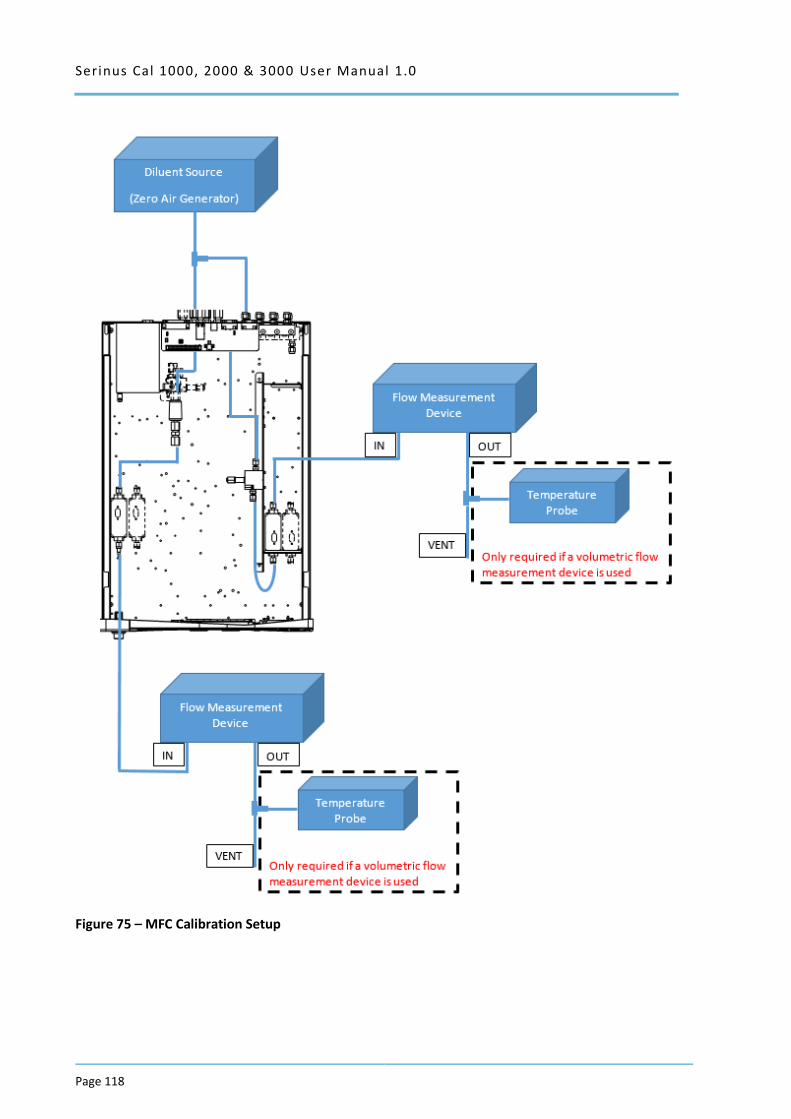
Serinus Cal 1000, 2000 & 3000 User Manual 1.0
Page 118
Figure 75 – MFC Calibration Setup
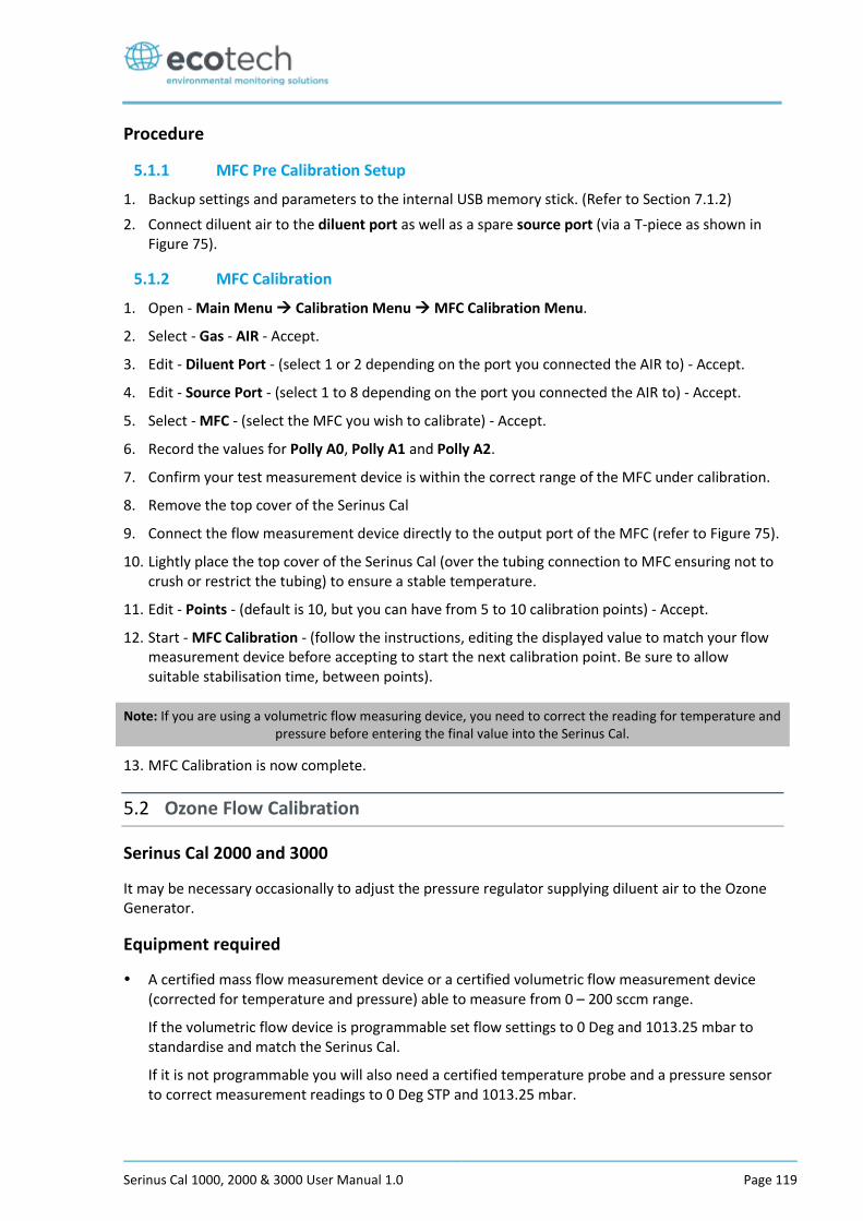
Serinus Cal 1000, 2000 & 3000 User Manual 1.0 Page 119
Procedure
5.1.1 MFC Pre Calibration Setup
1. Backup settings and parameters to the internal USB memory stick. (Refer to Section 7.1.2)
2. Connect diluent air to the diluent port as well as a spare source port (via a T-piece as shown in Figure 75).
5.1.2 MFC Calibration
1. Open - Main Menu Calibration Menu MFC Calibration Menu.
2. Select - Gas - AIR - Accept.
3. Edit - Diluent Port - (select 1 or 2 depending on the port you connected the AIR to) - Accept.
4. Edit - Source Port - (select 1 to 8 depending on the port you connected the AIR to) - Accept.
5. Select - MFC - (select the MFC you wish to calibrate) - Accept.
6. Record the values for Polly A0, Polly A1 and Polly A2.
7. Confirm your test measurement device is within the correct range of the MFC under calibration.
8. Remove the top cover of the Serinus Cal
9. Connect the flow measurement device directly to the output port of the MFC (refer to Figure 75).
10. Lightly place the top cover of the Serinus Cal (over the tubing connection to MFC ensuring not to crush or restrict the tubing) to ensure a stable temperature.
11. Edit - Points - (default is 10, but you can have from 5 to 10 calibration points) - Accept.
12. Start - MFC Calibration - (follow the instructions, editing the displayed value to match your flow measurement device before accepting to start the next calibration point. Be sure to allow suitable stabilisation time, between points).
Note: If you are using a volumetric flow measuring device, you need to correct the reading for temperature and pressure before entering the final value into the Serinus Cal.
13. MFC Calibration is now complete.
5.2 Ozone Flow Calibration
Serinus Cal 2000 and 3000
It may be necessary occasionally to adjust the pressure regulator supplying diluent air to the Ozone Generator.
Equipment required
A certified mass flow measurement device or a certified volumetric flow measurement device (corrected for temperature and pressure) able to measure from 0 – 200 sccm range.
If the volumetric flow device is programmable set flow settings to 0 Deg and 1013.25 mbar to standardise and match the Serinus Cal.
If it is not programmable you will also need a certified temperature probe and a pressure sensor to correct measurement readings to 0 Deg STP and 1013.25 mbar.
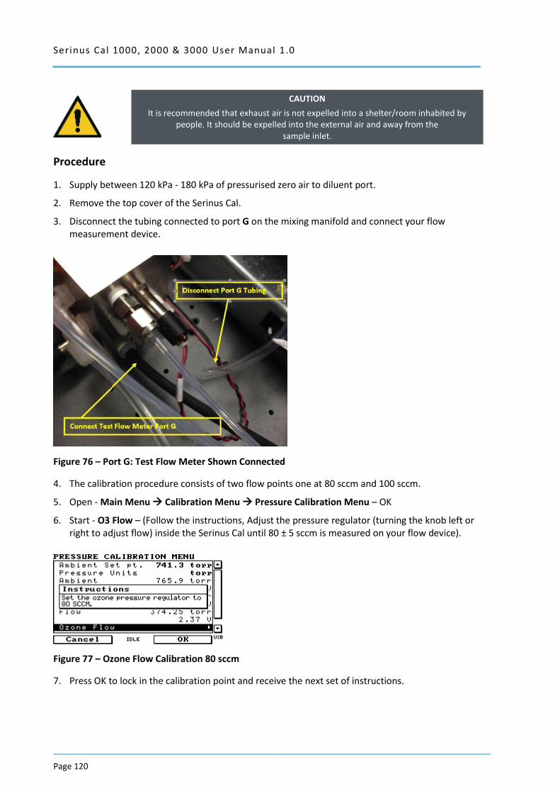
Serinus Cal 1000, 2000 & 3000 User Manual 1.0
Page 120
CAUTION
It is recommended that exhaust air is not expelled into a shelter/room inhabited by people. It should be expelled into the external air and away from the
sample inlet.
Procedure
1. Supply between 120 kPa - 180 kPa of pressurised zero air to diluent port.
2. Remove the top cover of the Serinus Cal.
3. Disconnect the tubing connected to port G on the mixing manifold and connect your flow measurement device.
Figure 76 – Port G: Test Flow Meter Shown Connected
4. The calibration procedure consists of two flow points one at 80 sccm and 100 sccm.
5. Open - Main Menu Calibration Menu Pressure Calibration Menu – OK
6. Start - O3 Flow – (Follow the instructions, Adjust the pressure regulator (turning the knob left or right to adjust flow) inside the Serinus Cal until 80 ± 5 sccm is measured on your flow device).
Figure 77 – Ozone Flow Calibration 80 sccm
7. Press OK to lock in the calibration point and receive the next set of instructions.
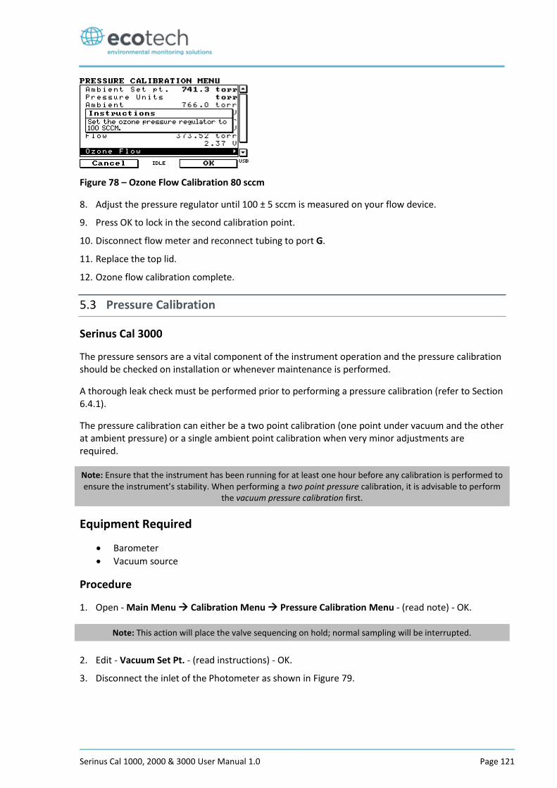
Serinus Cal 1000, 2000 & 3000 User Manual 1.0 Page 121
Figure 78 – Ozone Flow Calibration 80 sccm
8. Adjust the pressure regulator until 100 ± 5 sccm is measured on your flow device.
9. Press OK to lock in the second calibration point.
10. Disconnect flow meter and reconnect tubing to port G.
11. Replace the top lid.
12. Ozone flow calibration complete.
5.3 Pressure Calibration
Serinus Cal 3000
The pressure sensors are a vital component of the instrument operation and the pressure calibration should be checked on installation or whenever maintenance is performed.
A thorough leak check must be performed prior to performing a pressure calibration (refer to Section 6.4.1).
The pressure calibration can either be a two point calibration (one point under vacuum and the other at ambient pressure) or a single ambient point calibration when very minor adjustments are required.
Note: Ensure that the instrument has been running for at least one hour before any calibration is performed to ensure the instrument’s stability. When performing a two point pressure calibration, it is advisable to perform
the vacuum pressure calibration first.
Equipment Required
Barometer
Vacuum source
Procedure
1. Open - Main Menu Calibration Menu Pressure Calibration Menu - (read note) - OK.
Note: This action will place the valve sequencing on hold; normal sampling will be interrupted.
2. Edit - Vacuum Set Pt. - (read instructions) - OK.
3. Disconnect the inlet of the Photometer as shown in Figure 79.
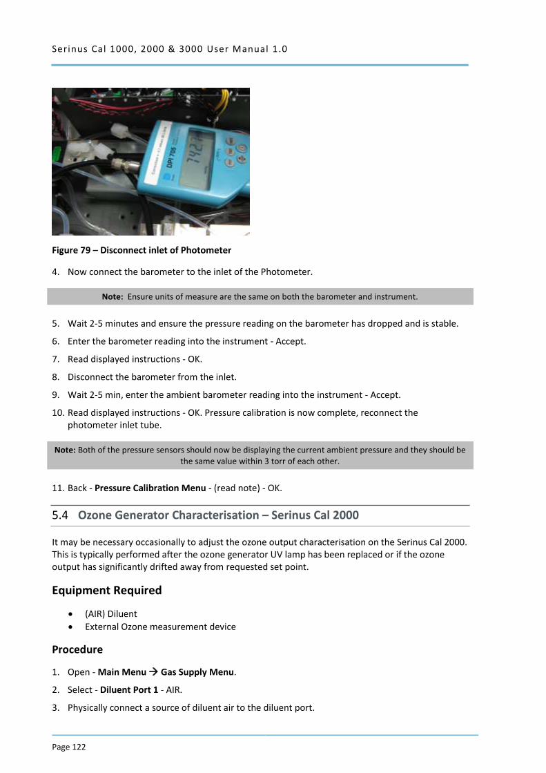
Serinus Cal 1000, 2000 & 3000 User Manual 1.0
Page 122
Figure 79 – Disconnect inlet of Photometer
4. Now connect the barometer to the inlet of the Photometer.
Note: Ensure units of measure are the same on both the barometer and instrument.
5. Wait 2-5 minutes and ensure the pressure reading on the barometer has dropped and is stable.
6. Enter the barometer reading into the instrument - Accept.
7. Read displayed instructions - OK.
8. Disconnect the barometer from the inlet.
9. Wait 2-5 min, enter the ambient barometer reading into the instrument - Accept.
10. Read displayed instructions - OK. Pressure calibration is now complete, reconnect the photometer inlet tube.
Note: Both of the pressure sensors should now be displaying the current ambient pressure and they should be the same value within 3 torr of each other.
11. Back - Pressure Calibration Menu - (read note) - OK.
5.4 Ozone Generator Characterisation – Serinus Cal 2000
It may be necessary occasionally to adjust the ozone output characterisation on the Serinus Cal 2000. This is typically performed after the ozone generator UV lamp has been replaced or if the ozone output has significantly drifted away from requested set point.
Equipment Required
(AIR) Diluent
External Ozone measurement device
Procedure
1. Open - Main Menu Gas Supply Menu.
2. Select - Diluent Port 1 - AIR.
3. Physically connect a source of diluent air to the diluent port.

Serinus Cal 1000, 2000 & 3000 User Manual 1.0 Page 123
4. Connect the one of the output ports to an external ozone measurement device.
5. Open - Main Menu Calibration Menu Ozone Calibration Menu.
6. Edit - Flow - (Enter the flow you want the calibration to be performed at).
7. Start - Ozone Calibration - (Wait until the external measurement device has a stable reading, enter that reading into the Serinus Cal.) - Accept
8. Repeat for each of the ten steps of the calibration process.
Note: Selecting Cancel will terminate the calibration process without making any changes.
5.5 Ozone Generator Characterisation – Serinus Cal 3000
It may be necessary occasionally to adjust the ozone output characterisation on the Serinus Cal 3000. This is typically performed after the ozone generator UV lamp has been replaced or if the ozone output has significantly drifted away from requested set point.
Note: This process will take at least 25min and may take up to 5 hours.
Equipment Required
(AIR) Diluent
Procedure
1. Open - Main Menu Gas Supply Menu.
2. Select - Diluent Port 1 - AIR - Accept.
3. Physically connect a source of diluent air to the diluent port.
4. Open - Main Menu Calibration Menu Ozone Calibration Menu.
5. Edit - Flow - (Enter the flow you want the calibration to be performed at).
6. Start - Ozone Calibration - (The firmware will now automatically step up through 10 points and adjust itself based on the internal photometer results).
7. The process is complete when no steps are displayed and the ‘Start’ button option returns.
Note: Pressing Stop or terminating the O3 Gen/Photometer point will terminate the calibration without saving any changes.
5.6 Photometer Calibration – Serinus Cal 3000
5.6.1 Photometer Pre Check
Note: Both your Serinus Cal 3000 and the external transfer standard should be powered up and active for a minimum of 2 hours.
Equipment required
External ozone transfer standard
Serinus Cal 1000, 2000 & 3000 User Manual 1.0
Page 124
(AIR) Diluent
Procedure
1. Open - Main Menu Gas Supply Menu.
2. Select - Diluent Port 1 - AIR - Accept.
3. Physically connect a source of diluent air to the diluent port.
4. Connect an external ozone transfer standard to one of the ports on the output manifold (if the external ozone transfer standard requires external reference air ensure it is connected to the same diluent air source used by the Serinus Cal 3000).
5. Create and run an O3 Gen/Photometer point at 100 % of range (normally 500 or 1000 ppb). Refer Section 3.2.2.6.
6. If the ozone measured on the Serinus Cal 3000 is outside ±2 % of the transfer standard then an adjustment will need to be made.
5.6.2 Photometer Calibration
Note: Both your Serinus Cal 3000 and the external transfer standard should be powered up and active for a minimum of 2 hours.
Equipment required
External ozone transfer standard
(AIR) Diluent
Procedure
1. Open - Main Menu Gas Supply Menu.
2. Select - Diluent Port 1 - AIR.
3. Physically connect a source of diluent air to the diluent port.
4. Connect an external ozone transfer standard to one of the ports on the output manifold (if the external ozone transfer standard requires external reference air ensure it is connected to the same diluent air source used by the Serinus Cal 3000).
5. Create and run O3 Gen/Photometer point at 100 % of range (normally 500 or 1000 ppb) refer to Section 3.2.2.6.
6. Open - Main Menu Calibration Menu.
7. Let the instrument stabilise, minimum 60 minutes.
8. Enter - Span Calibrate O3 - (Enter the reading from the transfer standard) - Accept.
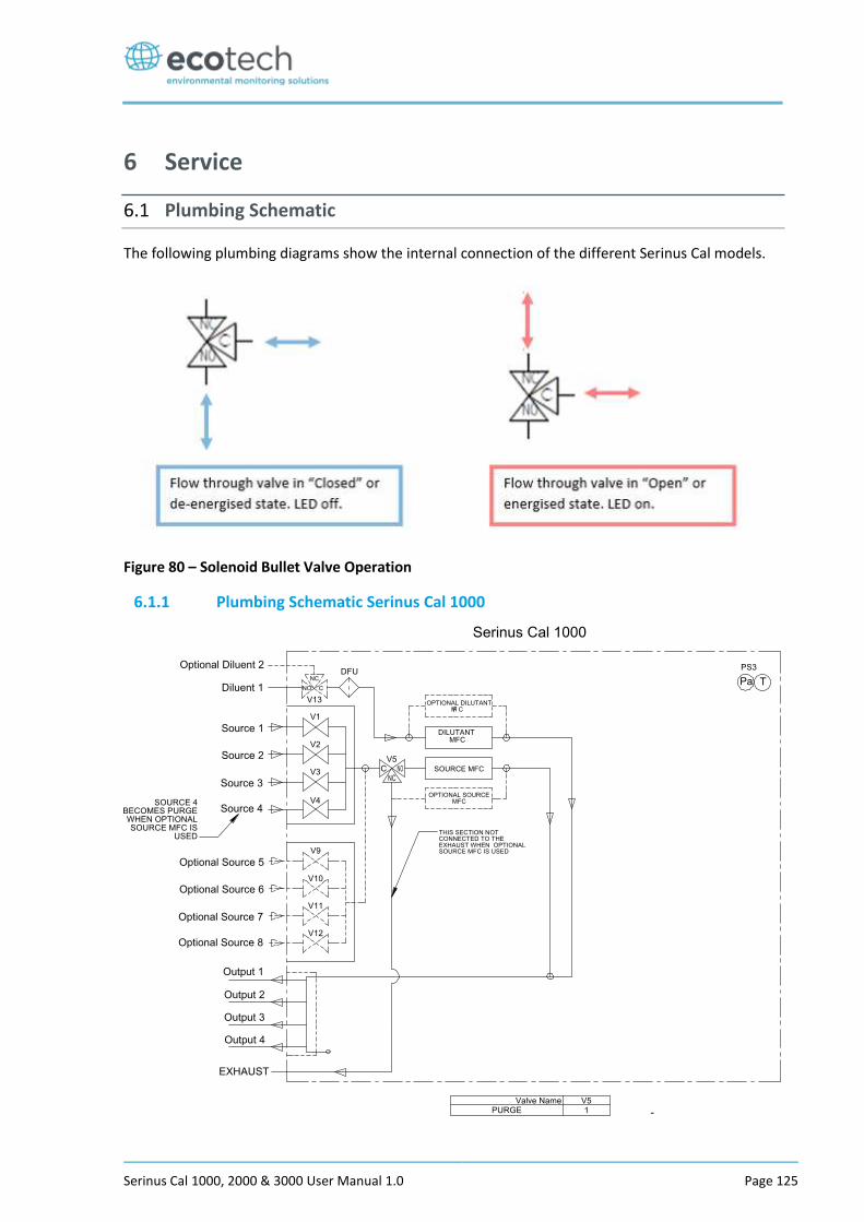
Serinus Cal 1000, 2000 & 3000 User Manual 1.0 Page 125
6 Service
6.1 Plumbing Schematic
The following plumbing diagrams show the internal connection of the different Serinus Cal models.
Figure 80 – Solenoid Bullet Valve Operation
6.1.1 Plumbing Schematic Serinus Cal 1000
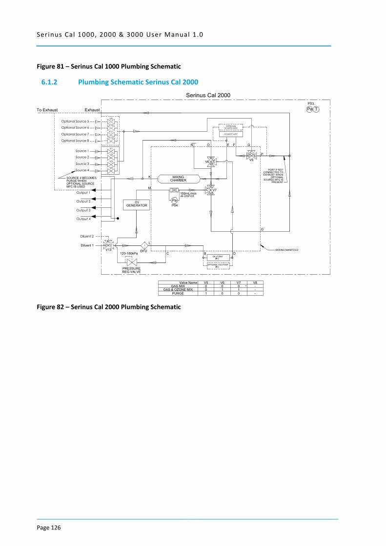
Serinus Cal 1000, 2000 & 3000 User Manual 1.0
Page 126
Figure 81 – Serinus Cal 1000 Plumbing Schematic
6.1.2 Plumbing Schematic Serinus Cal 2000
Figure 82 – Serinus Cal 2000 Plumbing Schematic
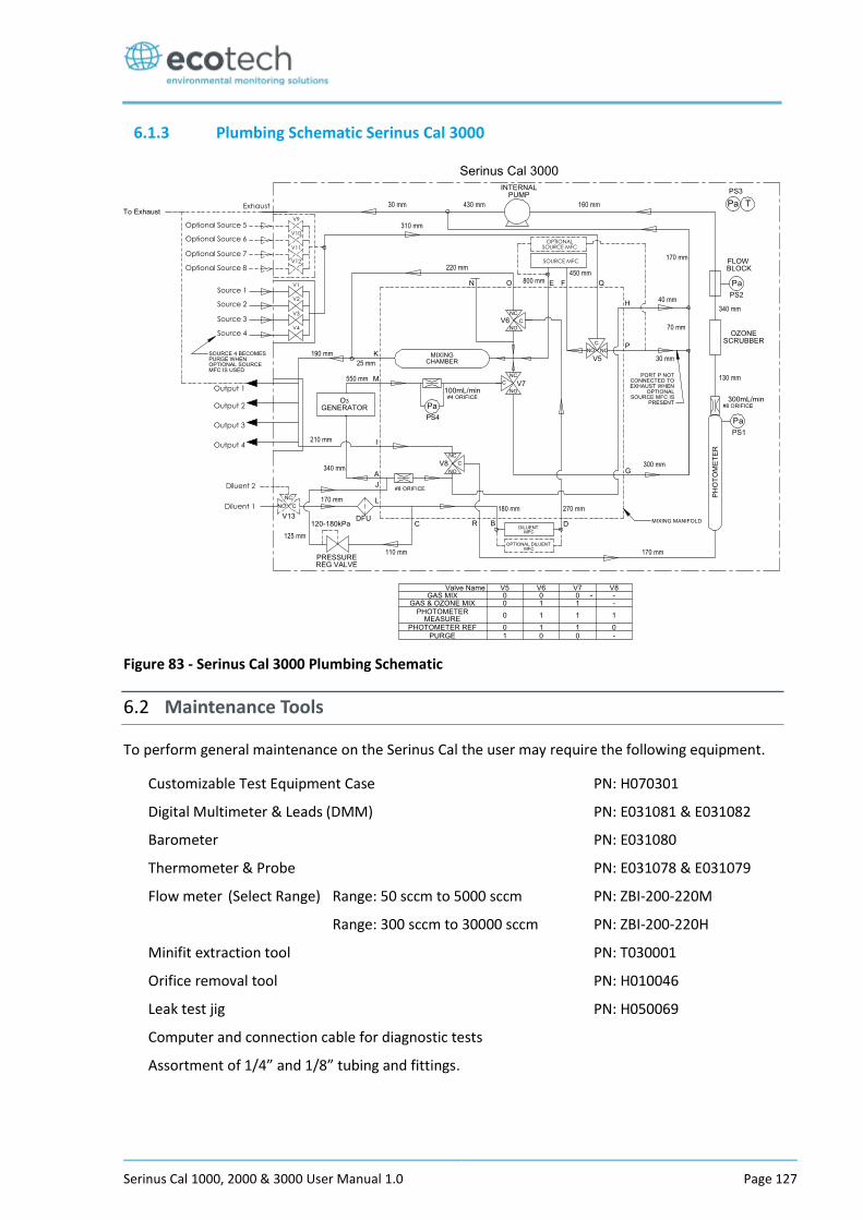
Serinus Cal 1000, 2000 & 3000 User Manual 1.0 Page 127
6.1.3 Plumbing Schematic Serinus Cal 3000
Figure 83 - Serinus Cal 3000 Plumbing Schematic
6.2 Maintenance Tools
To perform general maintenance on the Serinus Cal the user may require the following equipment.
Customizable Test Equipment Case PN: H070301
Digital Multimeter & Leads (DMM) PN: E031081 & E031082
Barometer PN: E031080
Thermometer & Probe PN: E031078 & E031079
Flow meter (Select Range) Range: 50 sccm to 5000 sccm PN: ZBI-200-220M
Range: 300 sccm to 30000 sccm PN: ZBI-200-220H
Minifit extraction tool PN: T030001
Orifice removal tool PN: H010046
Leak test jig PN: H050069
Computer and connection cable for diagnostic tests
Assortment of 1/4” and 1/8” tubing and fittings.
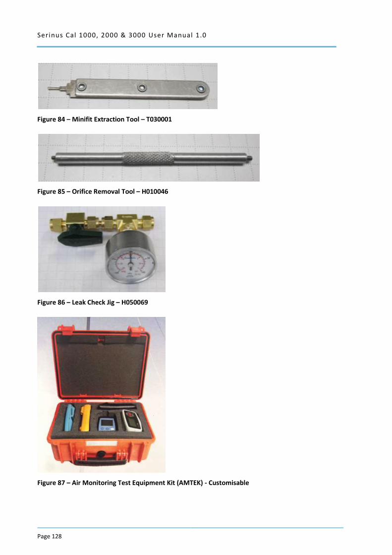
Serinus Cal 1000, 2000 & 3000 User Manual 1.0
Page 128
Figure 84 – Minifit Extraction Tool – T030001
Figure 85 – Orifice Removal Tool – H010046
Figure 86 – Leak Check Jig – H050069
Figure 87 – Air Monitoring Test Equipment Kit (AMTEK) - Customisable
Serinus Cal 1000, 2000 & 3000 User Manual 1.0 Page 129
6.3 Maintenance Schedule
The Serinus Cal requires minimal ongoing maintenance. The intervals for calibration are determined by compliance standards that vary in different countries. The following is recommended by Ecotech as a guide and compliance with local regulatory or international standards is the responsibility of the user.
Table 6 – Maintenance Schedule
Monthly
Serinus Cal 1000, 2000, 3000 Check Status Menu and all parameters PASS/Ok.
Backup configuration files to USB.
Serinus Cal 3000 UV Lamp check. Input Pot nominal value less than 255 otherwise replace lamp.
6 Monthly
Serinus Cal 1000, 2000, 3000 MFC Multipoint Calibration
Serinus Cal 3000 Photometer Calibration – Transfer Standard (Portable)
Yearly
Serinus Cal 2000, 3000 Ozone Flow Calibration
6.4 Maintenance Procedures
6.4.1 Leak Check Serinus Cal 3000
A Leak check is recommended when any service or repair of the internal valves or pneumatics has been performed or a leak is suspected.
Tools required:
Vacuum leak test device (Ecotech Leak Jig PN: H050069)
Assorted plugs and tubing supplied with instrument (Serinus Accessories Kit PN: H010136)
6.4.1.1 Leak Check - Full
1. With the instrument powered on set the operation Mode to IDLE and remove lid.
2. Connect a vacuum leak test device to the Exhaust port of the analyser.
3. Plug all the output ports (O1 – O4) and the Diluent port with the provided kynar plugs.
4. Disconnect ports J and C from the pressure regulator and cap the ends of the tube with 1/8” black caps. The pressure regulator has an internal bleed valve and your leak test will not work if the pressure regulator is not isolated.
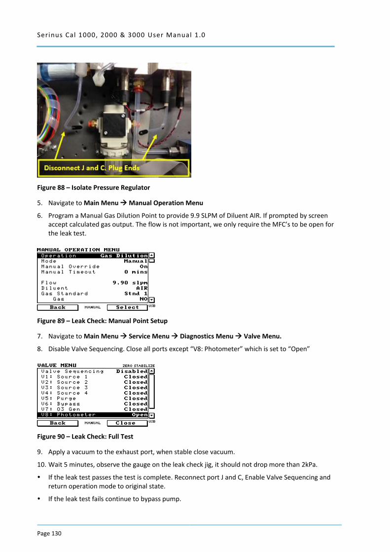
Serinus Cal 1000, 2000 & 3000 User Manual 1.0
Page 130
Figure 88 – Isolate Pressure Regulator
5. Navigate to Main Menu Manual Operation Menu
6. Program a Manual Gas Dilution Point to provide 9.9 SLPM of Diluent AIR. If prompted by screen accept calculated gas output. The flow is not important, we only require the MFC’s to be open for the leak test.
Figure 89 – Leak Check: Manual Point Setup
7. Navigate to Main Menu Service Menu Diagnostics Menu Valve Menu.
8. Disable Valve Sequencing. Close all ports except “V8: Photometer” which is set to “Open”
Figure 90 – Leak Check: Full Test
9. Apply a vacuum to the exhaust port, when stable close vacuum.
10. Wait 5 minutes, observe the gauge on the leak check jig, it should not drop more than 2kPa.
If the leak test passes the test is complete. Reconnect port J and C, Enable Valve Sequencing and return operation mode to original state.
If the leak test fails continue to bypass pump.
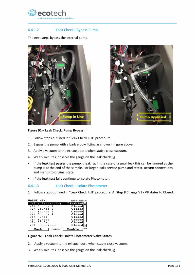
Serinus Cal 1000, 2000 & 3000 User Manual 1.0 Page 131
6.4.1.2 Leak Check - Bypass Pump
The next steps bypass the internal pump.
Figure 91 – Leak Check: Pump Bypass
1. Follow steps outlined in “Leak Check Full” procedure.
2. Bypass the pump with a barb elbow fitting as shown in figure above.
3. Apply a vacuum to the exhaust port, when stable close vacuum.
4. Wait 5 minutes, observe the gauge on the leak check jig.
If the leak test passes the pump is leaking. In the case of a small leak this can be ignored as the pump is at the end of the sample. For larger leaks service pump and retest. Return connections and menus to original state.
If the leak test fails continue to isolate Photometer.
6.4.1.3 Leak Check - Isolate Photometer
1. Follow steps outlined in “Leak Check Full” procedure. At Step 8 Change V1 - V8 states to Closed.
Figure 92 – Leak Check: Isolate Photometer Valve States
2. Apply a vacuum to the exhaust port, when stable close vacuum.
3. Wait 5 minutes, observe the gauge on the leak check jig.

Serinus Cal 1000, 2000 & 3000 User Manual 1.0
Page 132
If a leak test fails the photometer plumbing is leaking. Refer to Figure 93 and work away from vacuum test device to further isolate and rectify leak.
If the leak test passes the photometer plumbing is not leaking. Continue steps to isolate MFC plumbing.
Figure 93 – Leak Check: Isolate Photometer Schematic
6.4.1.4 Leak Check – Isolate MFC’s
1. Connect vacuum test device to any output port (O1 – O4). Plug all other output ports and diluent port.
2. Disable valve sequencing and set V1 – V8 states to all Closed.
3. Apply a vacuum to the output port, when stable close vacuum.
4. Wait 5 minutes, observe the gauge on the leak check jig.
If the leak test fails the MFC plumbing is leaking. Refer to Figure 94 and work away from the vacuum test device to further isolate and rectify leak.
If the leak test passes the test is complete.
5. Remove caps and re-connect ports J and C.
6. Enable Valve Sequencing and return instrument to previous operating Mode.
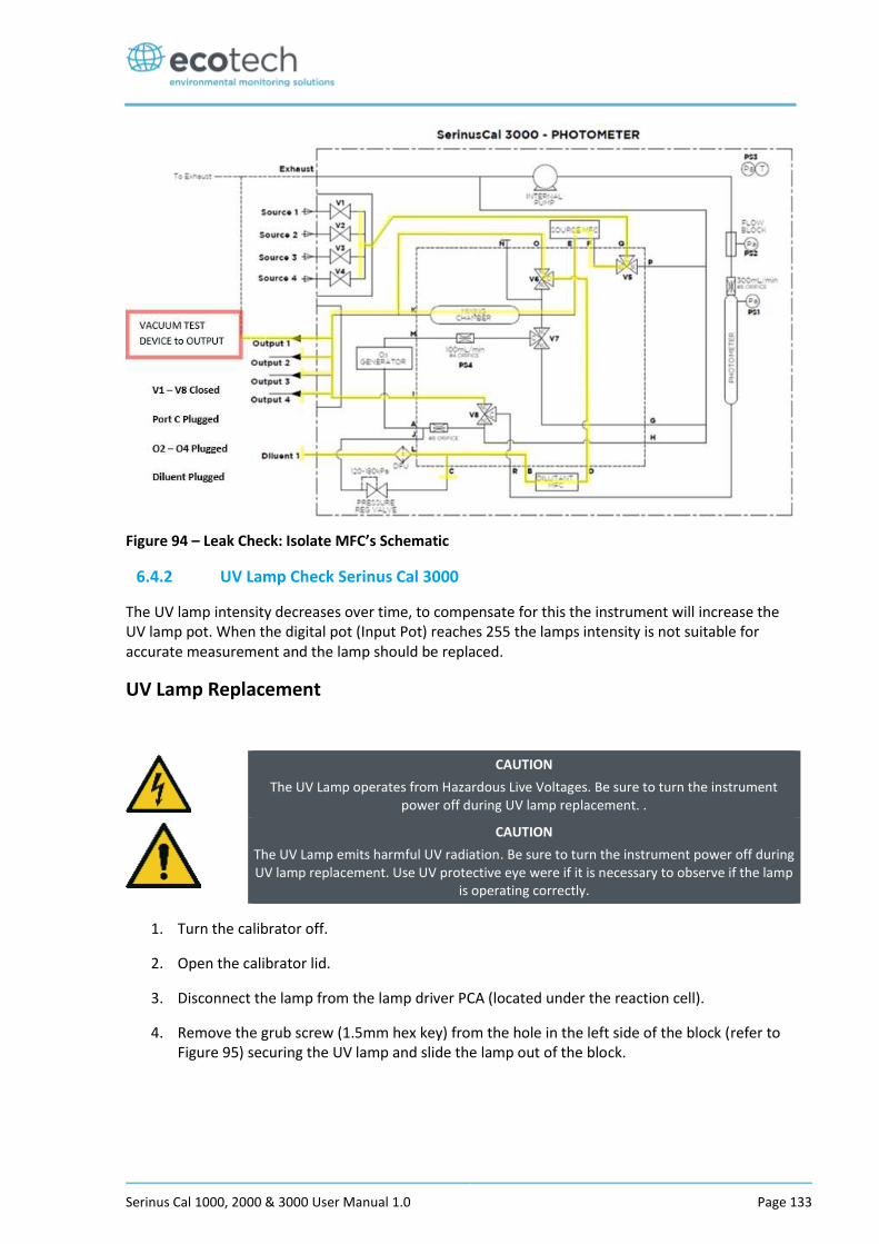
Serinus Cal 1000, 2000 & 3000 User Manual 1.0 Page 133
Figure 94 – Leak Check: Isolate MFC’s Schematic
6.4.2 UV Lamp Check Serinus Cal 3000
The UV lamp intensity decreases over time, to compensate for this the instrument will increase the UV lamp pot. When the digital pot (Input Pot) reaches 255 the lamps intensity is not suitable for accurate measurement and the lamp should be replaced.
UV Lamp Replacement
CAUTION
The UV Lamp operates from Hazardous Live Voltages. Be sure to turn the instrument power off during UV lamp replacement. .
CAUTION
The UV Lamp emits harmful UV radiation. Be sure to turn the instrument power off during UV lamp replacement. Use UV protective eye were if it is necessary to observe if the lamp
is operating correctly.
1. Turn the calibrator off.
2. Open the calibrator lid.
3. Disconnect the lamp from the lamp driver PCA (located under the reaction cell).
4. Remove the grub screw (1.5mm hex key) from the hole in the left side of the block (refer to Figure 95) securing the UV lamp and slide the lamp out of the block.
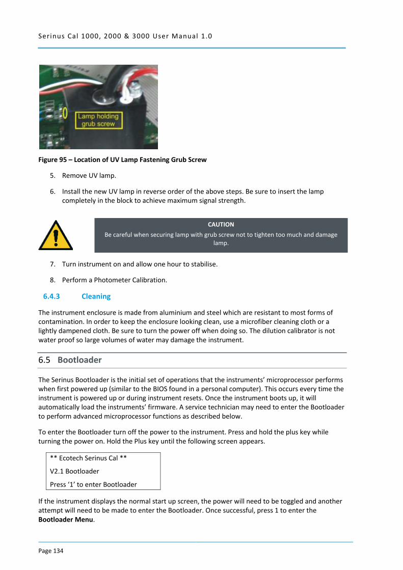
Serinus Cal 1000, 2000 & 3000 User Manual 1.0
Page 134
Figure 95 – Location of UV Lamp Fastening Grub Screw
5. Remove UV lamp.
6. Install the new UV lamp in reverse order of the above steps. Be sure to insert the lamp completely in the block to achieve maximum signal strength.
CAUTION
Be careful when securing lamp with grub screw not to tighten too much and damage lamp.
7. Turn instrument on and allow one hour to stabilise.
8. Perform a Photometer Calibration.
6.4.3 Cleaning
The instrument enclosure is made from aluminium and steel which are resistant to most forms of contamination. In order to keep the enclosure looking clean, use a microfiber cleaning cloth or a lightly dampened cloth. Be sure to turn the power off when doing so. The dilution calibrator is not water proof so large volumes of water may damage the instrument.
6.5 Bootloader
The Serinus Bootloader is the initial set of operations that the instruments’ microprocessor performs when first powered up (similar to the BIOS found in a personal computer). This occurs every time the instrument is powered up or during instrument resets. Once the instrument boots up, it will automatically load the instruments’ firmware. A service technician may need to enter the Bootloader to perform advanced microprocessor functions as described below.
To enter the Bootloader turn off the power to the instrument. Press and hold the plus key while turning the power on. Hold the Plus key until the following screen appears.
** Ecotech Serinus Cal **
V2.1 Bootloader
Press ‘1’ to enter Bootloader
If the instrument displays the normal start up screen, the power will need to be toggled and another attempt will need to be made to enter the Bootloader. Once successful, press 1 to enter the Bootloader Menu.
Serinus Cal 1000, 2000 & 3000 User Manual 1.0 Page 135
6.5.1 Display Help Screen
Once in the Bootloader screen it is possible to redisplay the help screen by pressing 1 on the key pad.
6.5.2 Communications Port Test
This test is very useful for fault finding communication issues. It allows a communication test to be carried out independent to any user settings or firmware revisions.
This command forces the following communication ports to output a string of characters: Serial Port RS232 #1, USB rear and Ethernet Port. The default baud rate is 38400 for the RS232 Serial Port. To initiate the test press the number 2 key from the Bootloader screen.
6.5.3 Updating Firmware
It is important for optimal performance of the instrument that the latest firmware is loaded. The latest firmware can be obtained by visiting Ecotech’s website:
http://www.ecotech.com/downloads/firmware
Or by emailing Ecotech at [email protected] or [email protected]
To update the firmware from a USB memory stick, use the following procedure:
USB Memory Stick Update
1. Turn the instrument off.
2. Place the USB memory stick with the new firmware (ensure that firmware is placed in a folder called FIRMWARE) in the front panel USB Port.
3. Enter the Bootloader (refer to Section 6.5).
4. Select option 3 (upgrade from USB memory stick), press 3 on the keypad.
5. Wait until the upgrade has completed.
6. Press 9 on the keypad to start the instrument with new firmware.
6.5.4 Updating Firmware from USB Memory Stick
USB Memory Stick Update
1. Turn instrument off.
2. Place USB memory stick with new firmware in the front panel USB port (Ensure that firmware is placed in a folder called FIRMWARE).
3. Enter the Bootloader (refer to Section 6.5).
4. Select option 3, (upgrade from USB memory stick) press 3 on keypad.
5. Wait till upgrade has completed.
6. Press 9 to start the calibrator with new firmware.
Serinus Cal 1000, 2000 & 3000 User Manual 1.0
Page 136
6.5.5 Erase All Settings
This command is only required if the instrument’s firmware has become unstable due to corrupted settings. To execute this command enter the Bootloader Menu (refer to Section 6.5) and press 4 on the keypad.
6.5.6 Start Calibrator
The start analyser command will simply initiate a firmware load by pressing 9 on the keypad from the Bootloader Menu. It is generally used after a firmware upgrade.

Serinus Cal 1000, 2000 & 3000 User Manual 1.0 Page 137
7 Troubleshooting
7.1.1 Main Screen Error Messages
In the event of an instrument fault an error message will be displayed on the lower left corner of the main screen. It will also be logged on the internal USB as an event in the “Event Log”.
In addition the green status led will change to orange or red.
A red light indicates that the instrument has a major failure and is not functioning.
An orange light indicates there is a minor problem with the instrument, but the instrument may still operate reliably.
A green light indicates that the instrument is working and there are no problems.
To determine which component/s of the instrument is causing a fault you can press the orange or red button to display a complete list of all current errors and warnings.
You can also find the complete list of self-diagnostic checks at;
Main Menu Analyser State Menu Status Menu
Refer to Section 3.5.16 of this manual has a complete table and explanation of all fault conditions. If you need further assistance please backup your instrument files to USB and contact Ecotech Service Support.
7.1.2 Ecotech Service Support Files – Backup Configuration and Parameters to USB
It is recommended you regularly backup the settings, parameters and data on the instruments USB.
In the event of a fault that requires Ecotech technical support please make copies of the following files and email to [email protected]. State the ID number and model of your instrument with a brief description of the problem.
Main Menu Service Menu Save Configuration CONFIG**.CFG
(NOTE: CONFIG99.CFG is the “Factory Default” file and it is recommended you keep this file unchanged.) ** Can be the month of each year for ease of multiple backups.
Main Menu Service Menu Save Parameters PARAM**.CFG
(NOTE: PARAM99.CFG is the “Factory Default” file and it is recommended you keep this file unchanged.) ** Can be the month of each year for ease of multiple backups.
Main Menu Service Menu Safely Remove the USB Stick and install into a computer. Figure shown below is a typical menu tree for the USB stick.
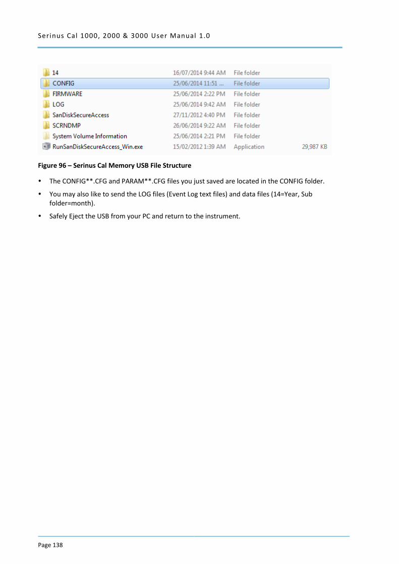
Serinus Cal 1000, 2000 & 3000 User Manual 1.0
Page 138
Figure 96 – Serinus Cal Memory USB File Structure
The CONFIG**.CFG and PARAM**.CFG files you just saved are located in the CONFIG folder.
You may also like to send the LOG files (Event Log text files) and data files (14=Year, Sub folder=month).
Safely Eject the USB from your PC and return to the instrument.
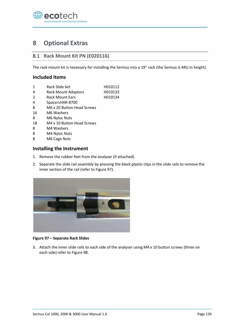
Serinus Cal 1000, 2000 & 3000 User Manual 1.0 Page 139
8 Optional Extras
8.1 Rack Mount Kit PN (E020116)
The rack mount kit is necessary for installing the Serinus into a 19” rack (the Serinus is 4RU in height).
Included Items
1 Rack Slide Set H010112 4 Rack Mount Adaptors H010133 2 Rack Mount Ears H010134 4 Spacers HAR-8700 8 M6 x 20 Button Head Screws 16 M6 Washers 8 M6 Nyloc Nuts 18 M4 x 10 Button Head Screws 8 M4 Washers 8 M4 Nyloc Nuts 8 M6 Cage Nuts
Installing the Instrument
1. Remove the rubber feet from the analyser (if attached).
2. Separate the slide rail assembly by pressing the black plastic clips in the slide rails to remove the inner section of the rail (refer to Figure 97).
Figure 97 – Separate Rack Slides
3. Attach the inner slide rails to each side of the analyser using M4 x 10 button screws (three on each side) refer to Figure 98.
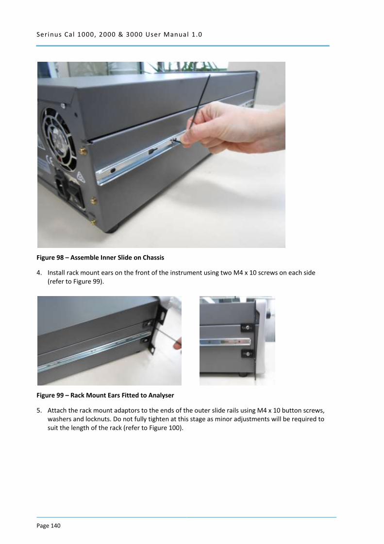
Serinus Cal 1000, 2000 & 3000 User Manual 1.0
Page 140
Figure 98 – Assemble Inner Slide on Chassis
4. Install rack mount ears on the front of the instrument using two M4 x 10 screws on each side (refer to Figure 99).
Figure 99 – Rack Mount Ears Fitted to Analyser
5. Attach the rack mount adaptors to the ends of the outer slide rails using M4 x 10 button screws, washers and locknuts. Do not fully tighten at this stage as minor adjustments will be required to suit the length of the rack (refer to Figure 100).

Serinus Cal 1000, 2000 & 3000 User Manual 1.0 Page 141
Figure 100 – Attach Rack Mount Adaptors to Outer Slides
6. Test fit the rack slide into your rack to determine the spacing of the rack mount adaptors.
Figure 101 – Test Fit the Rack Slide Assembly into your Rack
7. Install the two assembled outer slide rails onto the left and right side of the rack securely with M6 bolts, washer and locknuts/cage nuts (refer to Figure 102).
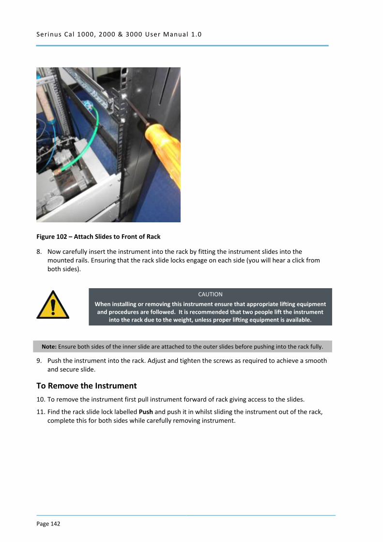
Serinus Cal 1000, 2000 & 3000 User Manual 1.0
Page 142
Figure 102 – Attach Slides to Front of Rack
8. Now carefully insert the instrument into the rack by fitting the instrument slides into the mounted rails. Ensuring that the rack slide locks engage on each side (you will hear a click from both sides).
CAUTION
When installing or removing this instrument ensure that appropriate lifting equipment and procedures are followed. It is recommended that two people lift the instrument
into the rack due to the weight, unless proper lifting equipment is available.
Note: Ensure both sides of the inner slide are attached to the outer slides before pushing into the rack fully.
9. Push the instrument into the rack. Adjust and tighten the screws as required to achieve a smooth and secure slide.
To Remove the Instrument
10. To remove the instrument first pull instrument forward of rack giving access to the slides.
11. Find the rack slide lock labelled Push and push it in whilst sliding the instrument out of the rack, complete this for both sides while carefully removing instrument.
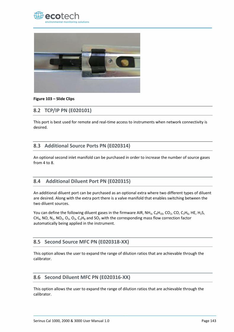
Serinus Cal 1000, 2000 & 3000 User Manual 1.0 Page 143
Figure 103 – Slide Clips
8.2 TCP/IP PN (E020101)
This port is best used for remote and real-time access to instruments when network connectivity is desired.
8.3 Additional Source Ports PN (E020314)
An optional second inlet manifold can be purchased in order to increase the number of source gases from 4 to 8.
8.4 Additional Diluent Port PN (E020315)
An additional diluent port can be purchased as an optional extra where two different types of diluent are desired. Along with the extra port there is a valve manifold that enables switching between the two diluent sources.
You can define the following diluent gases in the firmware AIR, NH3, C4H10, CO2, CO, C2H6, HE, H2S, CH4, NO, N2, NO2, O2, O3, C3H8 and SO2 with the corresponding mass flow correction factor automatically being applied in the instrument.
8.5 Second Source MFC PN (E020318-XX)
This option allows the user to expand the range of dilution ratios that are achievable through the calibrator.
8.6 Second Diluent MFC PN (E020316-XX)
This option allows the user to expand the range of dilution ratios that are achievable through the calibrator.

Serinus Cal 1000, 2000 & 3000 User Manual 1.0
Page 144
This page is intentionally blank
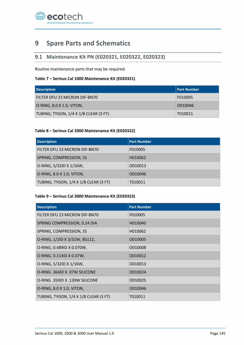
Serinus Cal 1000, 2000 & 3000 User Manual 1.0 Page 145
9 Spare Parts and Schematics
9.1 Maintenance Kit PN (E020321, E020322, E020323)
Routine maintenance parts that may be required.
Table 7 – Serinus Cal 1000 Maintenance Kit (E020321)
Description Part Number
FILTER DFU 23 MICRON DIF-BN70 F010005
O-RING, 8.0 X 1.0, VITON, O010046
TUBING, TYGON, 1/4 X 1/8 CLEAR (3 FT) T010011
Table 8 – Serinus Cal 2000 Maintenance Kit (E020322)
Description Part Number
FILTER DFU 23 MICRON DIF-BN70 F010005
SPRING, COMPRESSION, SS H010062
O-RING, 5/32ID X 1/16W, O010013
O-RING, 8.0 X 1.0, VITON, O010046
TUBING, TYGON, 1/4 X 1/8 CLEAR (3 FT) T010011
Table 9 – Serinus Cal 3000 Maintenance Kit (E020323)
Description Part Number
FILTER DFU 23 MICRON DIF-BN70 F010005
SPRING COMPRESSION, 0.24 DIA H010040
SPRING, COMPRESSION, SS H010062
O-RING, 1/2ID X 3/32W, BS112, O010005
O-RING, 0.489ID X 0.070W, O010008
O-RING, 0.114ID X 0.07W, O010012
O-RING, 5/32ID X 1/16W, O010013
O-RING .364ID X .07W SILICONE O010024
O-RING .359ID X .139W SILICONE O010025
O-RING, 8.0 X 1.0, VITON, O010046
TUBING, TYGON, 1/4 X 1/8 CLEAR (3 FT) T010011
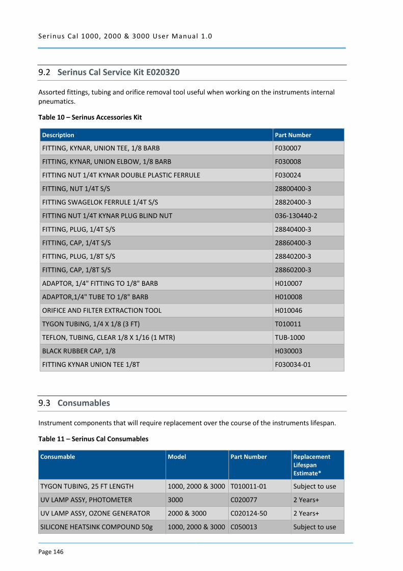
Serinus Cal 1000, 2000 & 3000 User Manual 1.0
Page 146
9.2 Serinus Cal Service Kit E020320
Assorted fittings, tubing and orifice removal tool useful when working on the instruments internal pneumatics.
Table 10 – Serinus Accessories Kit
Description Part Number
FITTING, KYNAR, UNION TEE, 1/8 BARB F030007
FITTING, KYNAR, UNION ELBOW, 1/8 BARB F030008
FITTING NUT 1/4T KYNAR DOUBLE PLASTIC FERRULE F030024
FITTING, NUT 1/4T S/S 28800400-3
FITTING SWAGELOK FERRULE 1/4T S/S 28820400-3
FITTING NUT 1/4T KYNAR PLUG BLIND NUT 036-130440-2
FITTING, PLUG, 1/4T S/S 28840400-3
FITTING, CAP, 1/4T S/S 28860400-3
FITTING, PLUG, 1/8T S/S 28840200-3
FITTING, CAP, 1/8T S/S 28860200-3
ADAPTOR, 1/4" FITTING TO 1/8" BARB H010007
ADAPTOR,1/4" TUBE TO 1/8" BARB H010008
ORIFICE AND FILTER EXTRACTION TOOL H010046
TYGON TUBING, 1/4 X 1/8 (3 FT) T010011
TEFLON, TUBING, CLEAR 1/8 X 1/16 (1 MTR) TUB-1000
BLACK RUBBER CAP, 1/8 H030003
FITTING KYNAR UNION TEE 1/8T F030034-01
9.3 Consumables
Instrument components that will require replacement over the course of the instruments lifespan.
Table 11 – Serinus Cal Consumables
Consumable Model Part Number Replacement Lifespan Estimate*
TYGON TUBING, 25 FT LENGTH 1000, 2000 & 3000 T010011-01 Subject to use
UV LAMP ASSY, PHOTOMETER 3000 C020077 2 Years+
UV LAMP ASSY, OZONE GENERATOR 2000 & 3000 C020124-50 2 Years+
SILICONE HEATSINK COMPOUND 50g 1000, 2000 & 3000 C050013 Subject to use
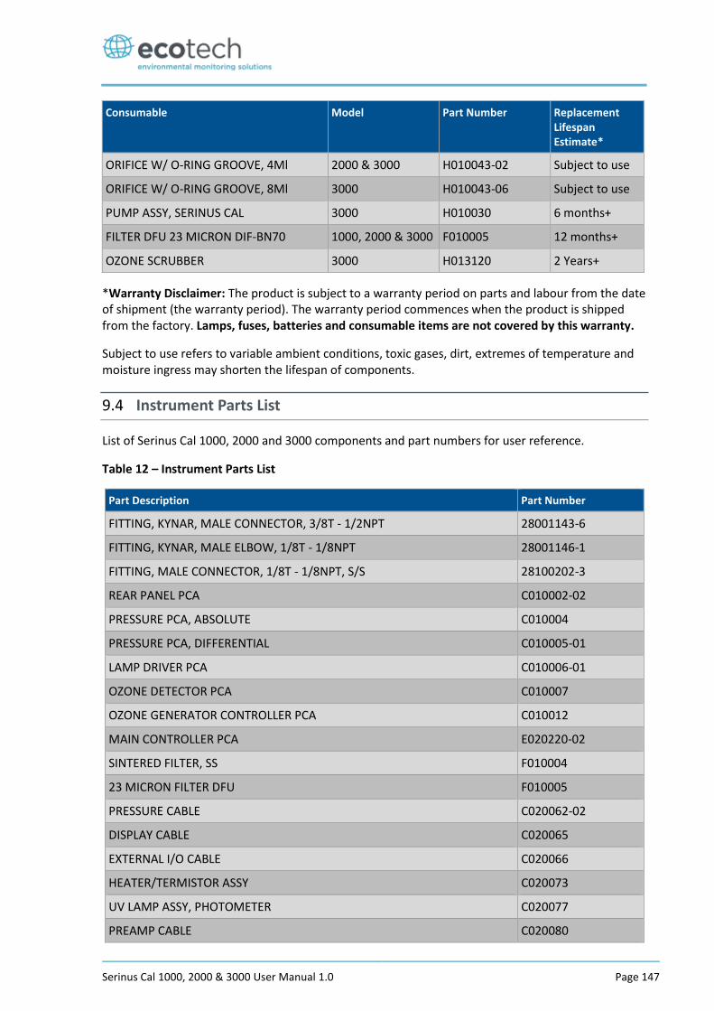
Serinus Cal 1000, 2000 & 3000 User Manual 1.0 Page 147
Consumable Model Part Number Replacement Lifespan Estimate*
ORIFICE W/ O-RING GROOVE, 4Ml 2000 & 3000 H010043-02 Subject to use
ORIFICE W/ O-RING GROOVE, 8Ml 3000 H010043-06 Subject to use
PUMP ASSY, SERINUS CAL 3000 H010030 6 months+
FILTER DFU 23 MICRON DIF-BN70 1000, 2000 & 3000 F010005 12 months+
OZONE SCRUBBER 3000 H013120 2 Years+
*Warranty Disclaimer: The product is subject to a warranty period on parts and labour from the date of shipment (the warranty period). The warranty period commences when the product is shipped from the factory. Lamps, fuses, batteries and consumable items are not covered by this warranty.
Subject to use refers to variable ambient conditions, toxic gases, dirt, extremes of temperature and moisture ingress may shorten the lifespan of components.
9.4 Instrument Parts List
List of Serinus Cal 1000, 2000 and 3000 components and part numbers for user reference.
Table 12 – Instrument Parts List
Part Description Part Number
FITTING, KYNAR, MALE CONNECTOR, 3/8T - 1/2NPT 28001143-6
FITTING, KYNAR, MALE ELBOW, 1/8T - 1/8NPT 28001146-1
FITTING, MALE CONNECTOR, 1/8T - 1/8NPT, S/S 28100202-3
REAR PANEL PCA C010002-02
PRESSURE PCA, ABSOLUTE C010004
PRESSURE PCA, DIFFERENTIAL C010005-01
LAMP DRIVER PCA C010006-01
OZONE DETECTOR PCA C010007
OZONE GENERATOR CONTROLLER PCA C010012
MAIN CONTROLLER PCA E020220-02
SINTERED FILTER, SS F010004
23 MICRON FILTER DFU F010005
PRESSURE CABLE C020062-02
DISPLAY CABLE C020065
EXTERNAL I/O CABLE C020066
HEATER/TERMISTOR ASSY C020073
UV LAMP ASSY, PHOTOMETER C020077
PREAMP CABLE C020080
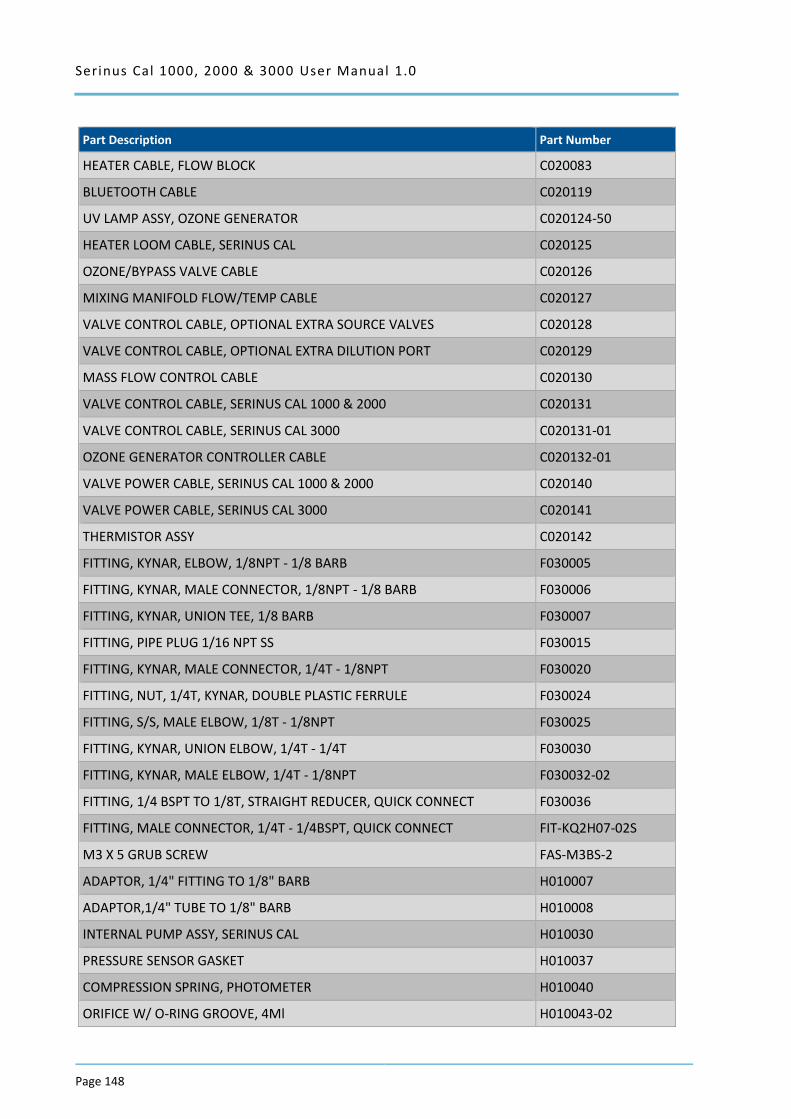
Serinus Cal 1000, 2000 & 3000 User Manual 1.0
Page 148
Part Description Part Number
HEATER CABLE, FLOW BLOCK C020083
BLUETOOTH CABLE C020119
UV LAMP ASSY, OZONE GENERATOR C020124-50
HEATER LOOM CABLE, SERINUS CAL C020125
OZONE/BYPASS VALVE CABLE C020126
MIXING MANIFOLD FLOW/TEMP CABLE C020127
VALVE CONTROL CABLE, OPTIONAL EXTRA SOURCE VALVES C020128
VALVE CONTROL CABLE, OPTIONAL EXTRA DILUTION PORT C020129
MASS FLOW CONTROL CABLE C020130
VALVE CONTROL CABLE, SERINUS CAL 1000 & 2000 C020131
VALVE CONTROL CABLE, SERINUS CAL 3000 C020131-01
OZONE GENERATOR CONTROLLER CABLE C020132-01
VALVE POWER CABLE, SERINUS CAL 1000 & 2000 C020140
VALVE POWER CABLE, SERINUS CAL 3000 C020141
THERMISTOR ASSY C020142
FITTING, KYNAR, ELBOW, 1/8NPT - 1/8 BARB F030005
FITTING, KYNAR, MALE CONNECTOR, 1/8NPT - 1/8 BARB F030006
FITTING, KYNAR, UNION TEE, 1/8 BARB F030007
FITTING, PIPE PLUG 1/16 NPT SS F030015
FITTING, KYNAR, MALE CONNECTOR, 1/4T - 1/8NPT F030020
FITTING, NUT, 1/4T, KYNAR, DOUBLE PLASTIC FERRULE F030024
FITTING, S/S, MALE ELBOW, 1/8T - 1/8NPT F030025
FITTING, KYNAR, UNION ELBOW, 1/4T - 1/4T F030030
FITTING, KYNAR, MALE ELBOW, 1/4T - 1/8NPT F030032-02
FITTING, 1/4 BSPT TO 1/8T, STRAIGHT REDUCER, QUICK CONNECT F030036
FITTING, MALE CONNECTOR, 1/4T - 1/4BSPT, QUICK CONNECT FIT-KQ2H07-02S
M3 X 5 GRUB SCREW FAS-M3BS-2
ADAPTOR, 1/4" FITTING TO 1/8" BARB H010007
ADAPTOR,1/4" TUBE TO 1/8" BARB H010008
INTERNAL PUMP ASSY, SERINUS CAL H010030
PRESSURE SENSOR GASKET H010037
COMPRESSION SPRING, PHOTOMETER H010040
ORIFICE W/ O-RING GROOVE, 4Ml H010043-02
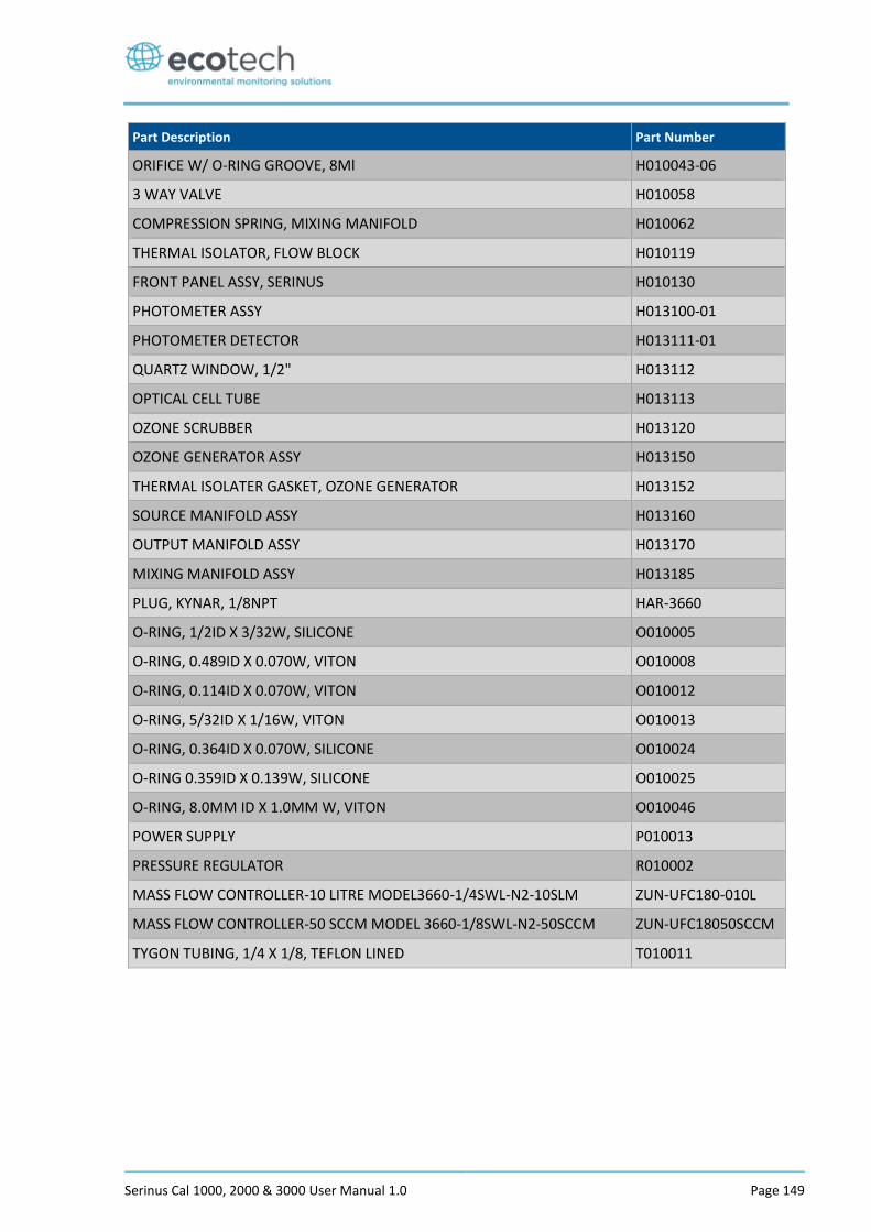
Serinus Cal 1000, 2000 & 3000 User Manual 1.0 Page 149
Part Description Part Number
ORIFICE W/ O-RING GROOVE, 8Ml H010043-06
3 WAY VALVE H010058
COMPRESSION SPRING, MIXING MANIFOLD H010062
THERMAL ISOLATOR, FLOW BLOCK H010119
FRONT PANEL ASSY, SERINUS H010130
PHOTOMETER ASSY H013100-01
PHOTOMETER DETECTOR H013111-01
QUARTZ WINDOW, 1/2" H013112
OPTICAL CELL TUBE H013113
OZONE SCRUBBER H013120
OZONE GENERATOR ASSY H013150
THERMAL ISOLATER GASKET, OZONE GENERATOR H013152
SOURCE MANIFOLD ASSY H013160
OUTPUT MANIFOLD ASSY H013170
MIXING MANIFOLD ASSY H013185
PLUG, KYNAR, 1/8NPT HAR-3660
O-RING, 1/2ID X 3/32W, SILICONE O010005
O-RING, 0.489ID X 0.070W, VITON O010008
O-RING, 0.114ID X 0.070W, VITON O010012
O-RING, 5/32ID X 1/16W, VITON O010013
O-RING, 0.364ID X 0.070W, SILICONE O010024
O-RING 0.359ID X 0.139W, SILICONE O010025
O-RING, 8.0MM ID X 1.0MM W, VITON O010046
POWER SUPPLY P010013
PRESSURE REGULATOR R010002
MASS FLOW CONTROLLER-10 LITRE MODEL3660-1/4SWL-N2-10SLM ZUN-UFC180-010L
MASS FLOW CONTROLLER-50 SCCM MODEL 3660-1/8SWL-N2-50SCCM ZUN-UFC18050SCCM
TYGON TUBING, 1/4 X 1/8, TEFLON LINED T010011
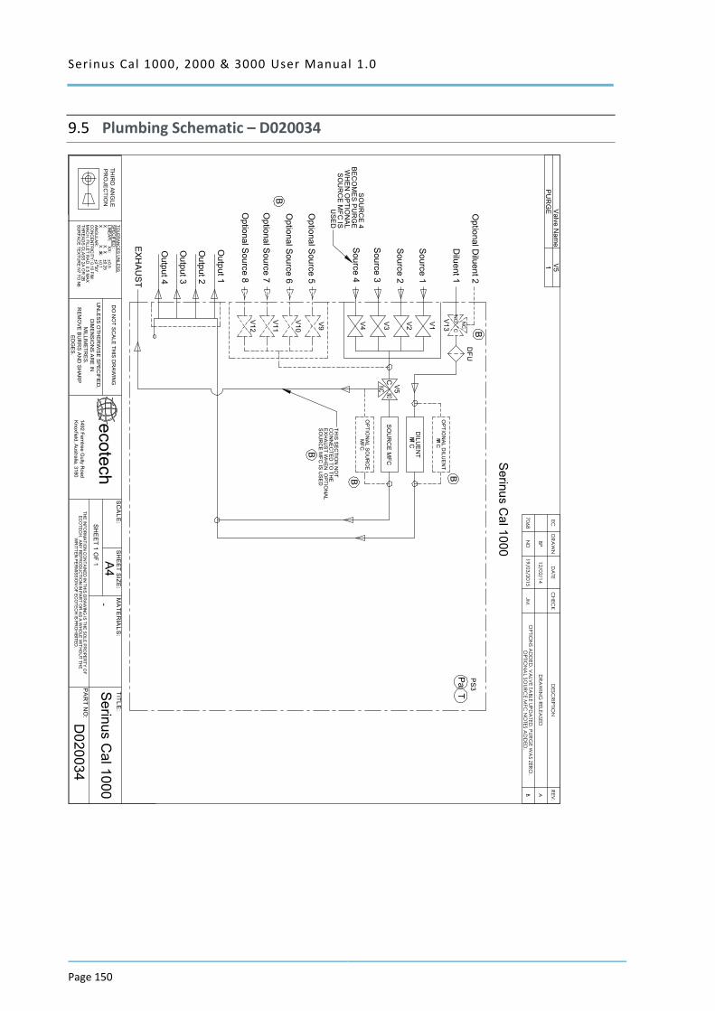
Serinus Cal 1000, 2000 & 3000 User Manual 1.0
Page 150
9.5 Plumbing Schematic – D020034
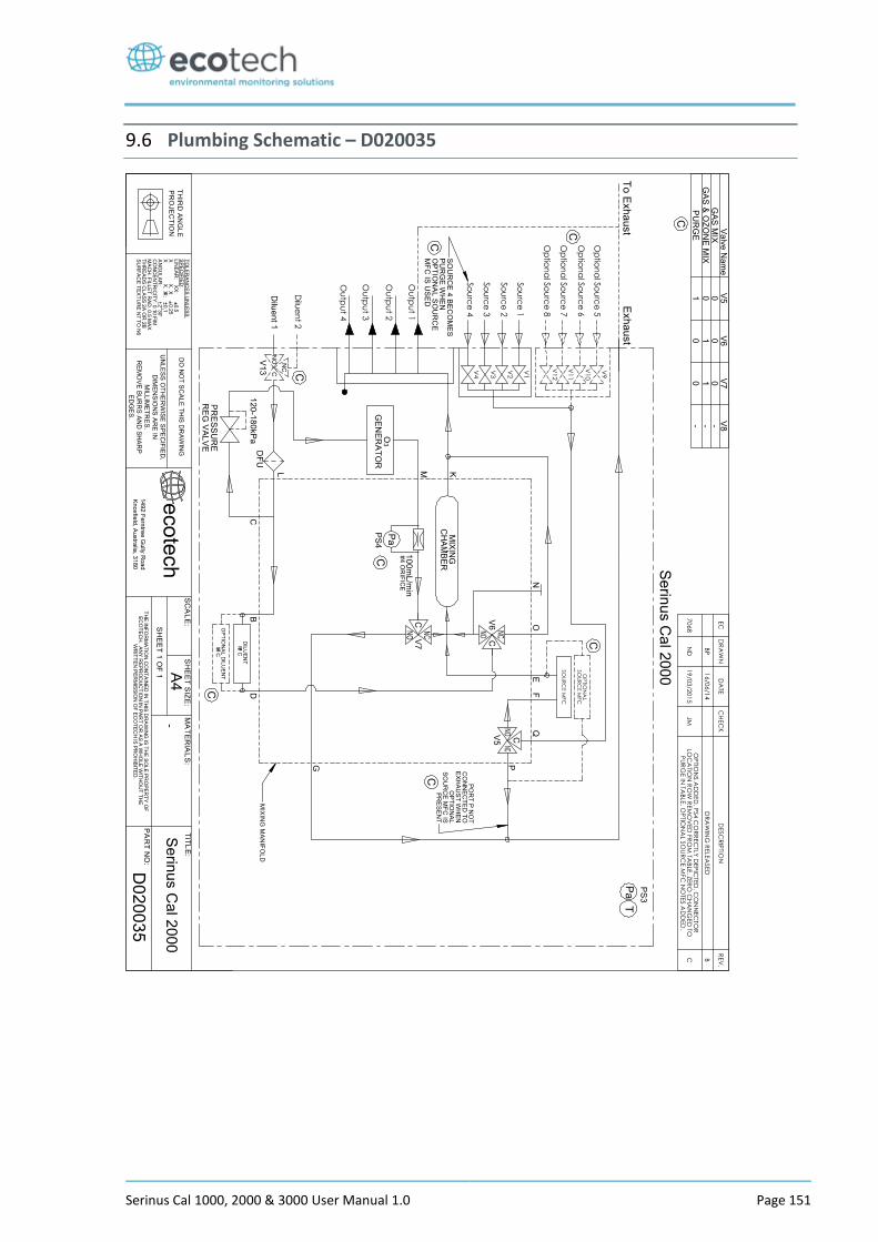
Serinus Cal 1000, 2000 & 3000 User Manual 1.0 Page 151
9.6 Plumbing Schematic – D020035
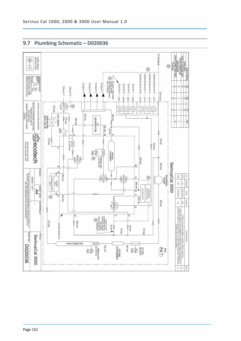
Serinus Cal 1000, 2000 & 3000 User Manual 1.0
Page 152
9.7 Plumbing Schematic – D020036
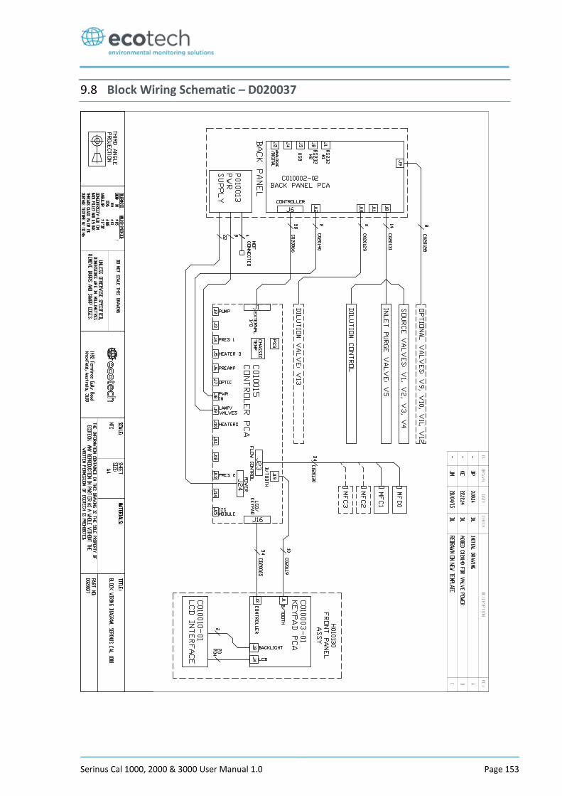
Serinus Cal 1000, 2000 & 3000 User Manual 1.0 Page 153
9.8 Block Wiring Schematic – D020037
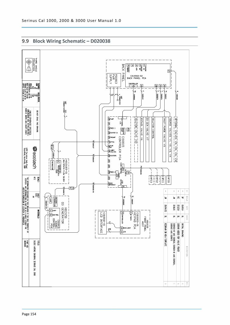
Serinus Cal 1000, 2000 & 3000 User Manual 1.0
Page 154
9.9 Block Wiring Schematic – D020038
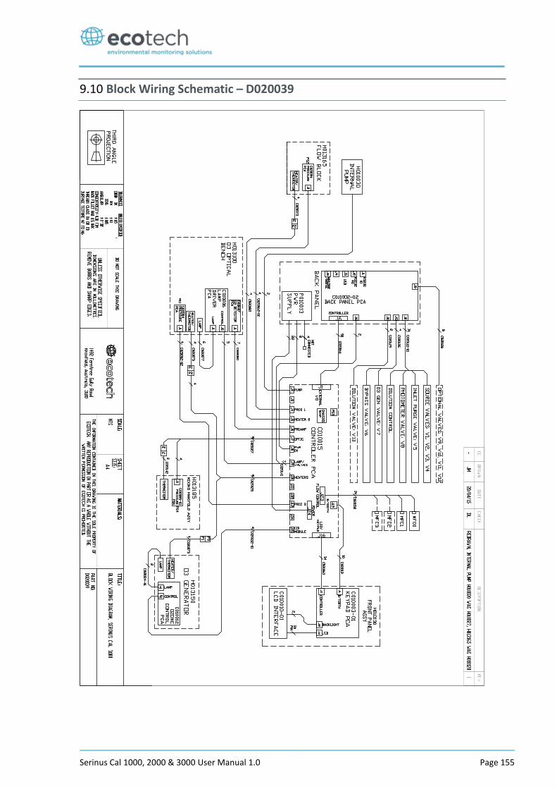
Serinus Cal 1000, 2000 & 3000 User Manual 1.0 Page 155
9.10 Block Wiring Schematic – D020039
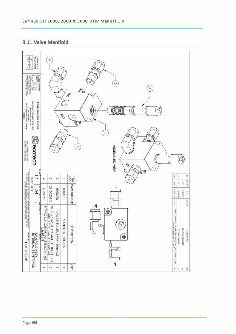
Serinus Cal 1000, 2000 & 3000 User Manual 1.0
Page 156
9.11 Valve Manifold
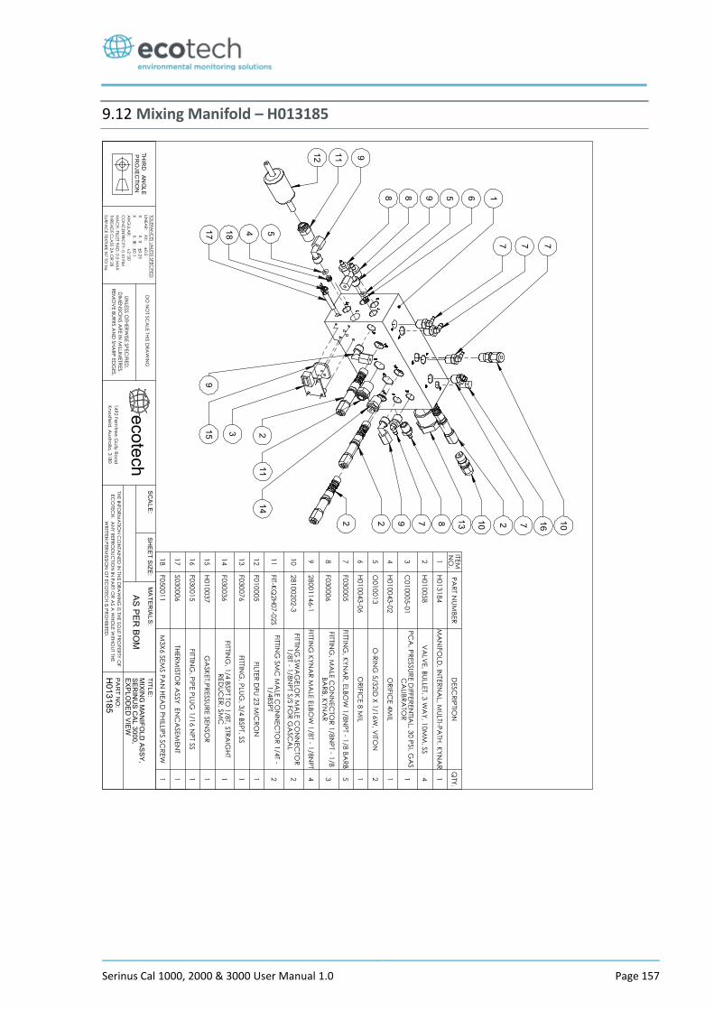
Serinus Cal 1000, 2000 & 3000 User Manual 1.0 Page 157
9.12 Mixing Manifold – H013185
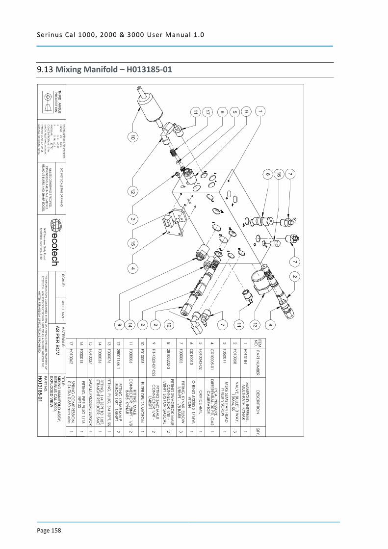
Serinus Cal 1000, 2000 & 3000 User Manual 1.0
Page 158
9.13 Mixing Manifold – H013185-01
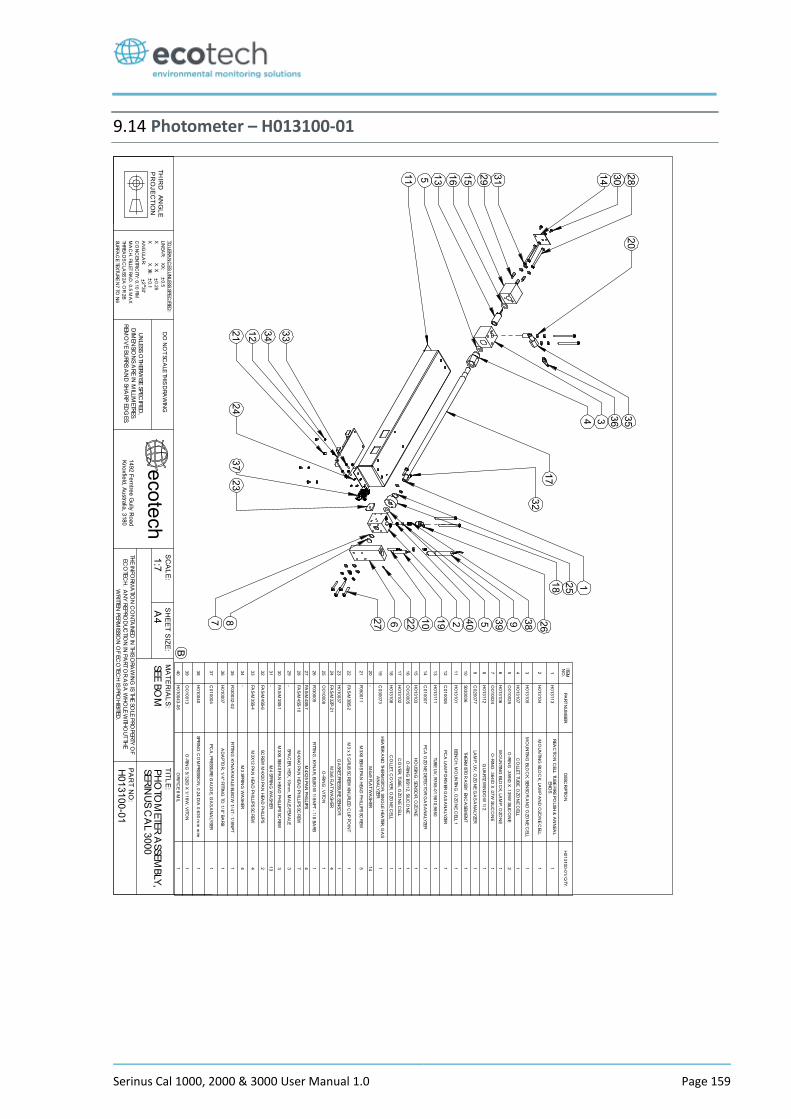
Serinus Cal 1000, 2000 & 3000 User Manual 1.0 Page 159
9.14 Photometer – H013100-01
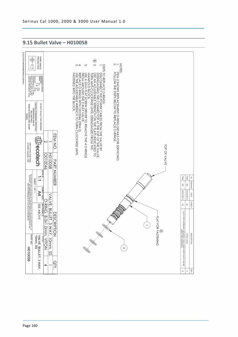
Serinus Cal 1000, 2000 & 3000 User Manual 1.0
Page 160
9.15 Bullet Valve – H010058
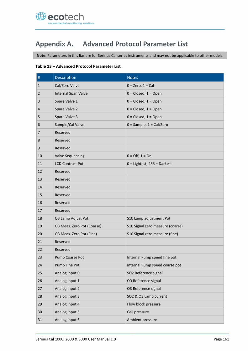
Serinus Cal 1000, 2000 & 3000 User Manual 1.0 Page 161
Appendix A. Advanced Protocol Parameter List
Note: Parameters in this lias are for Serinus Cal series instruments and may not be applicable to other models.
Table 13 – Advanced Protocol Parameter List
# Description Notes
1 Cal/Zero Valve 0 = Zero, 1 = Cal
2 Internal Span Valve 0 = Closed, 1 = Open
3 Spare Valve 1 0 = Closed, 1 = Open
4 Spare Valve 2 0 = Closed, 1 = Open
5 Spare Valve 3 0 = Closed, 1 = Open
6 Sample/Cal Valve 0 = Sample, 1 = Cal/Zero
7 Reserved
8 Reserved
9 Reserved
10 Valve Sequencing 0 = Off, 1 = On
11 LCD Contrast Pot 0 = Lightest, 255 = Darkest
12 Reserved
13 Reserved
14 Reserved
15 Reserved
16 Reserved
17 Reserved
18 O3 Lamp Adjust Pot S10 Lamp adjustment Pot
19 O3 Meas. Zero Pot (Coarse) S10 Signal zero measure (coarse)
20 O3 Meas. Zero Pot (Fine) S10 Signal zero measure (fine)
21 Reserved
22 Reserved
23 Pump Coarse Pot Internal Pump speed fine pot
24 Pump Fine Pot Internal Pump speed coarse pot
25 Analog input 0 SO2 Reference signal
26 Analog input 1 CO Reference signal
27 Analog input 2 O3 Reference signal
28 Analog input 3 SO2 & O3 Lamp current
29 Analog input 4 Flow block pressure
30 Analog input 5 Cell pressure
31 Analog input 6 Ambient pressure
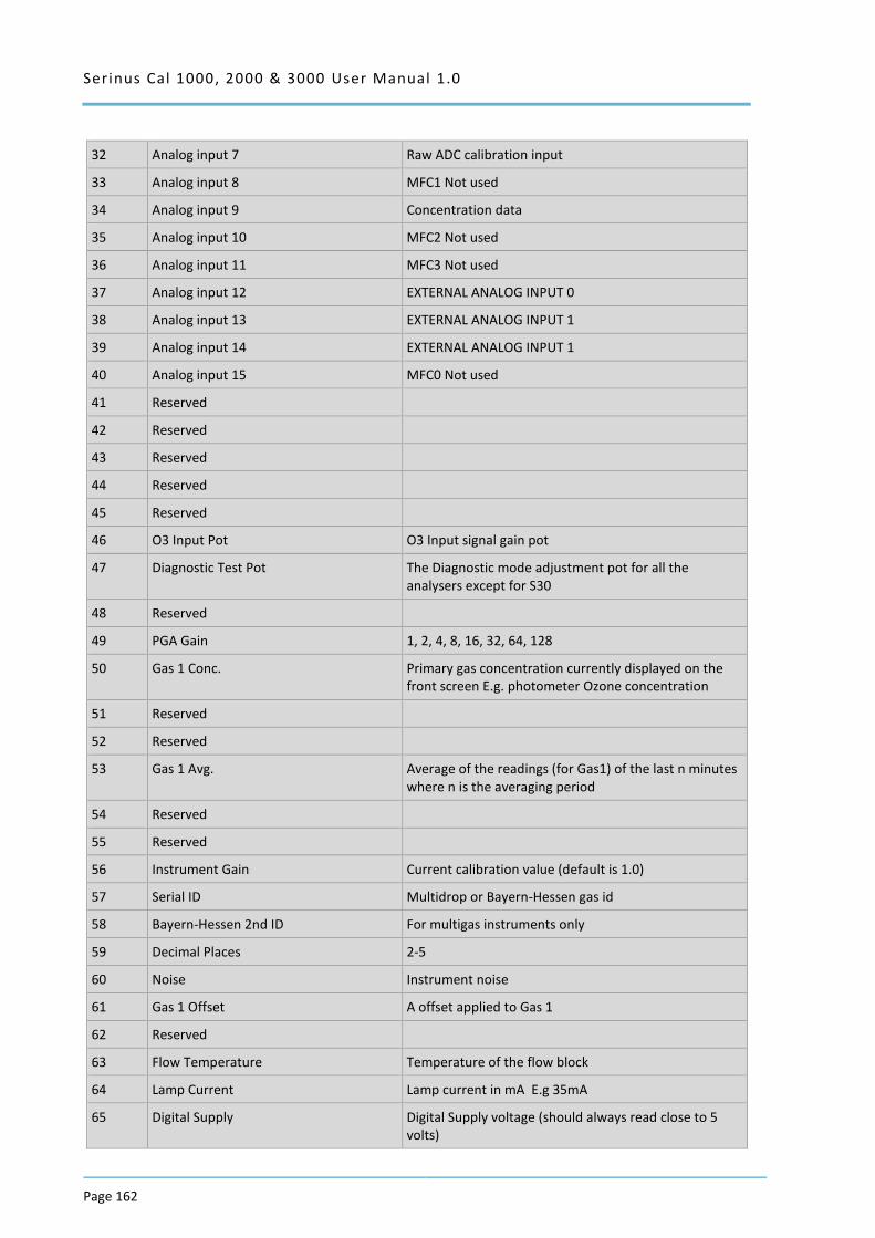
Serinus Cal 1000, 2000 & 3000 User Manual 1.0
Page 162
32 Analog input 7 Raw ADC calibration input
33 Analog input 8 MFC1 Not used
34 Analog input 9 Concentration data
35 Analog input 10 MFC2 Not used
36 Analog input 11 MFC3 Not used
37 Analog input 12 EXTERNAL ANALOG INPUT 0
38 Analog input 13 EXTERNAL ANALOG INPUT 1
39 Analog input 14 EXTERNAL ANALOG INPUT 1
40 Analog input 15 MFC0 Not used
41 Reserved
42 Reserved
43 Reserved
44 Reserved
45 Reserved
46 O3 Input Pot O3 Input signal gain pot
47 Diagnostic Test Pot The Diagnostic mode adjustment pot for all the analysers except for S30
48 Reserved
49 PGA Gain 1, 2, 4, 8, 16, 32, 64, 128
50 Gas 1 Conc. Primary gas concentration currently displayed on the front screen E.g. photometer Ozone concentration
51 Reserved
52 Reserved
53 Gas 1 Avg. Average of the readings (for Gas1) of the last n minutes where n is the averaging period
54 Reserved
55 Reserved
56 Instrument Gain Current calibration value (default is 1.0)
57 Serial ID Multidrop or Bayern-Hessen gas id
58 Bayern-Hessen 2nd ID For multigas instruments only
59 Decimal Places 2-5
60 Noise Instrument noise
61 Gas 1 Offset A offset applied to Gas 1
62 Reserved
63 Flow Temperature Temperature of the flow block
64 Lamp Current Lamp current in mA E.g 35mA
65 Digital Supply Digital Supply voltage (should always read close to 5 volts)
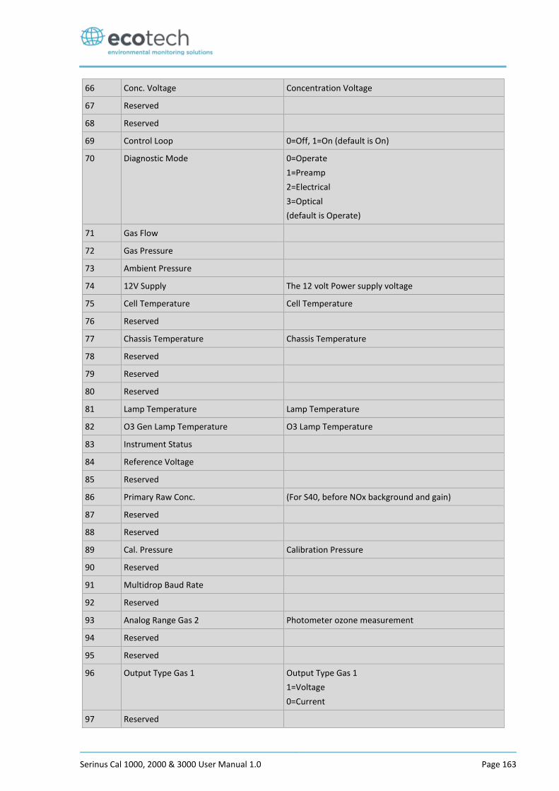
Serinus Cal 1000, 2000 & 3000 User Manual 1.0 Page 163
66 Conc. Voltage Concentration Voltage
67 Reserved
68 Reserved
69 Control Loop 0=Off, 1=On (default is On)
70 Diagnostic Mode 0=Operate
1=Preamp
2=Electrical
3=Optical
(default is Operate)
71 Gas Flow
72 Gas Pressure
73 Ambient Pressure
74 12V Supply The 12 volt Power supply voltage
75 Cell Temperature Cell Temperature
76 Reserved
77 Chassis Temperature Chassis Temperature
78 Reserved
79 Reserved
80 Reserved
81 Lamp Temperature Lamp Temperature
82 O3 Gen Lamp Temperature O3 Lamp Temperature
83 Instrument Status
84 Reference Voltage
85 Reserved
86 Primary Raw Conc. (For S40, before NOx background and gain)
87 Reserved
88 Reserved
89 Cal. Pressure Calibration Pressure
90 Reserved
91 Multidrop Baud Rate
92 Reserved
93 Analog Range Gas 2 Photometer ozone measurement
94 Reserved
95 Reserved
96 Output Type Gas 1 Output Type Gas 1
1=Voltage
0=Current
97 Reserved
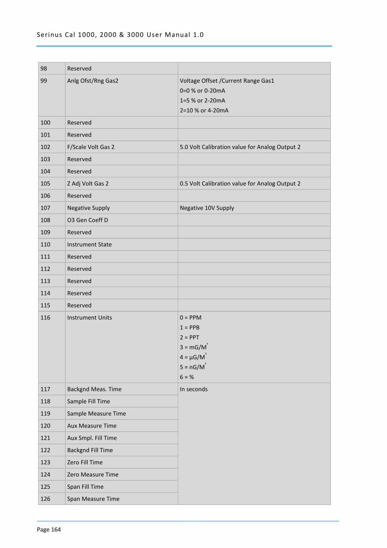
Serinus Cal 1000, 2000 & 3000 User Manual 1.0
Page 164
98 Reserved
99 Anlg Ofst/Rng Gas2 Voltage Offset /Current Range Gas1
0=0 % or 0-20mA
1=5 % or 2-20mA
2=10 % or 4-20mA
100 Reserved
101 Reserved
102 F/Scale Volt Gas 2 5.0 Volt Calibration value for Analog Output 2
103 Reserved
104 Reserved
105 Z Adj Volt Gas 2 0.5 Volt Calibration value for Analog Output 2
106 Reserved
107 Negative Supply Negative 10V Supply
108 O3 Gen Coeff D
109 Reserved
110 Instrument State
111 Reserved
112 Reserved
113 Reserved
114 Reserved
115 Reserved
116 Instrument Units 0 = PPM
1 = PPB
2 = PPT
3 = mG/M³
4 = µG/M³
5 = nG/M³
6 = %
117 Backgnd Meas. Time In seconds
118 Sample Fill Time
119 Sample Measure Time
120 Aux Measure Time
121 Aux Smpl. Fill Time
122 Backgnd Fill Time
123 Zero Fill Time
124 Zero Measure Time
125 Span Fill Time
126 Span Measure Time
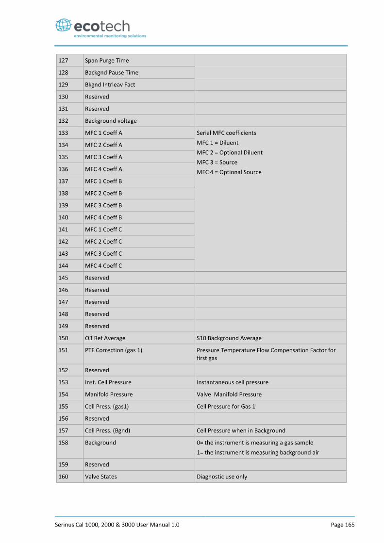
Serinus Cal 1000, 2000 & 3000 User Manual 1.0 Page 165
127 Span Purge Time
128 Backgnd Pause Time
129 Bkgnd Intrleav Fact
130 Reserved
131 Reserved
132 Background voltage
133 MFC 1 Coeff A Serial MFC coefficients
MFC 1 = Diluent
MFC 2 = Optional Diluent
MFC 3 = Source
MFC 4 = Optional Source
134 MFC 2 Coeff A
135 MFC 3 Coeff A
136 MFC 4 Coeff A
137 MFC 1 Coeff B
138 MFC 2 Coeff B
139 MFC 3 Coeff B
140 MFC 4 Coeff B
141 MFC 1 Coeff C
142 MFC 2 Coeff C
143 MFC 3 Coeff C
144 MFC 4 Coeff C
145 Reserved
146 Reserved
147 Reserved
148 Reserved
149 Reserved
150 O3 Ref Average S10 Background Average
151 PTF Correction (gas 1) Pressure Temperature Flow Compensation Factor for first gas
152 Reserved
153 Inst. Cell Pressure Instantaneous cell pressure
154 Manifold Pressure Valve Manifold Pressure
155 Cell Press. (gas1) Cell Pressure for Gas 1
156 Reserved
157 Cell Press. (Bgnd) Cell Pressure when in Background
158 Background 0= the instrument is measuring a gas sample
1= the instrument is measuring background air
159 Reserved
160 Valve States Diagnostic use only
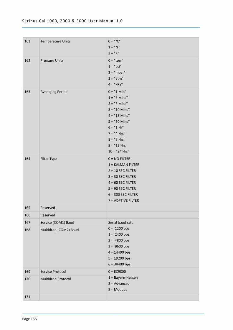
Serinus Cal 1000, 2000 & 3000 User Manual 1.0
Page 166
161 Temperature Units 0 = "°C"
1 = "°F"
2 = "K"
162 Pressure Units 0 = "torr"
1 = "psi"
2 = "mbar"
3 = "atm"
4 = "kPa"
163 Averaging Period 0 = "1 Min"
1 = "3 Mins"
2 = "5 Mins"
3 = "10 Mins"
4 = "15 Mins"
5 = "30 Mins"
6 = "1 Hr"
7 = "4 Hrs"
8 = "8 Hrs"
9 = "12 Hrs"
10 = "24 Hrs"
164 Filter Type 0 = NO FILTER
1 = KALMAN FILTER
2 = 10 SEC FILTER
3 = 30 SEC FILTER
4 = 60 SEC FILTER
5 = 90 SEC FILTER
6 = 300 SEC FILTER
7 = ADPTIVE FILTER
165 Reserved
166 Reserved
167 Service (COM1) Baud Serial baud rate
0 = 1200 bps
1 = 2400 bps
2 = 4800 bps
3 = 9600 bps
4 = 14400 bps
5 = 19200 bps
6 = 38400 bps
168 Multidrop (COM2) Baud
169 Service Protocol 0 = EC9800
1 = Bayern-Hessen
2 = Advanced
3 = Modbus
170 Multidrop Protocol
171
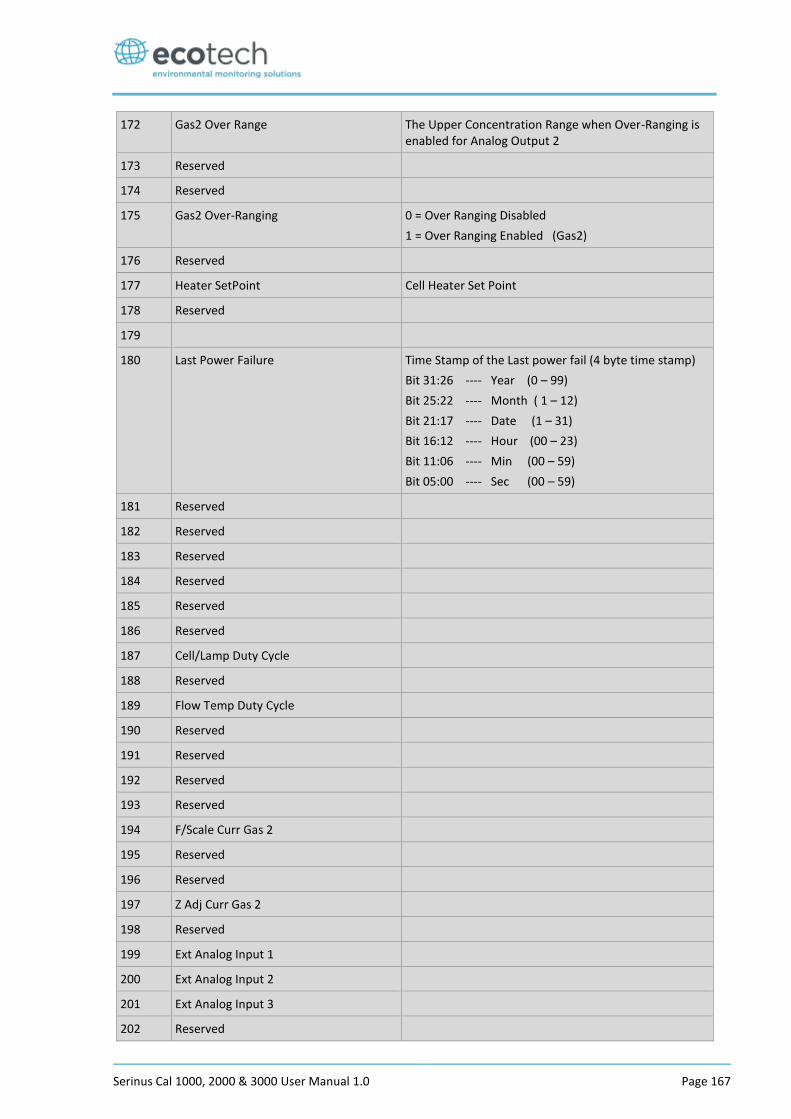
Serinus Cal 1000, 2000 & 3000 User Manual 1.0 Page 167
172 Gas2 Over Range The Upper Concentration Range when Over-Ranging is enabled for Analog Output 2
173 Reserved
174 Reserved
175 Gas2 Over-Ranging 0 = Over Ranging Disabled
1 = Over Ranging Enabled (Gas2)
176 Reserved
177 Heater SetPoint Cell Heater Set Point
178 Reserved
179
180 Last Power Failure Time Stamp of the Last power fail (4 byte time stamp)
Bit 31:26 ---- Year (0 – 99)
Bit 25:22 ---- Month ( 1 – 12)
Bit 21:17 ---- Date (1 – 31)
Bit 16:12 ---- Hour (00 – 23)
Bit 11:06 ---- Min (00 – 59)
Bit 05:00 ---- Sec (00 – 59)
181 Reserved
182 Reserved
183 Reserved
184 Reserved
185 Reserved
186 Reserved
187 Cell/Lamp Duty Cycle
188 Reserved
189 Flow Temp Duty Cycle
190 Reserved
191 Reserved
192 Reserved
193 Reserved
194 F/Scale Curr Gas 2
195 Reserved
196 Reserved
197 Z Adj Curr Gas 2
198 Reserved
199 Ext Analog Input 1
200 Ext Analog Input 2
201 Ext Analog Input 3
202 Reserved
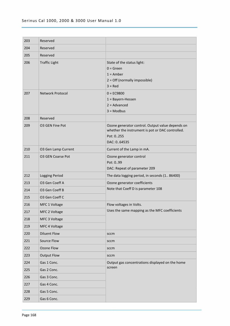
Serinus Cal 1000, 2000 & 3000 User Manual 1.0
Page 168
203 Reserved
204 Reserved
205 Reserved
206 Traffic Light State of the status light:
0 = Green
1 = Amber
2 = Off (normally impossible)
3 = Red
207 Network Protocol 0 = EC9800
1 = Bayern-Hessen
2 = Advanced
3 = Modbus
208 Reserved
209 O3 GEN Fine Pot Ozone generator control. Output value depends on whether the instrument is pot or DAC controlled.
Pot: 0..255
DAC: 0..64535
210 O3 Gen Lamp Current Current of the Lamp in mA.
211 O3 GEN Coarse Pot Ozone generator control
Pot: 0..99
DAC: Repeat of parameter 209
212 Logging Period The data logging period, in seconds (1.. 86400)
213 O3 Gen Coeff A Ozone generator coefficients
Note that Coeff D is parameter 108 214 O3 Gen Coeff B
215 O3 Gen Coeff C
216 MFC 1 Voltage Flow voltages in Volts.
Uses the same mapping as the MFC coefficients 217 MFC 2 Voltage
218 MFC 3 Voltage
219 MFC 4 Voltage
220 Diluent Flow sccm
221 Source Flow sccm
222 Ozone Flow sccm
223 Output Flow sccm
224 Gas 1 Conc. Output gas concentrations displayed on the home screen
225 Gas 2 Conc.
226 Gas 3 Conc.
227 Gas 4 Conc.
228 Gas 5 Conc.
229 Gas 6 Conc.
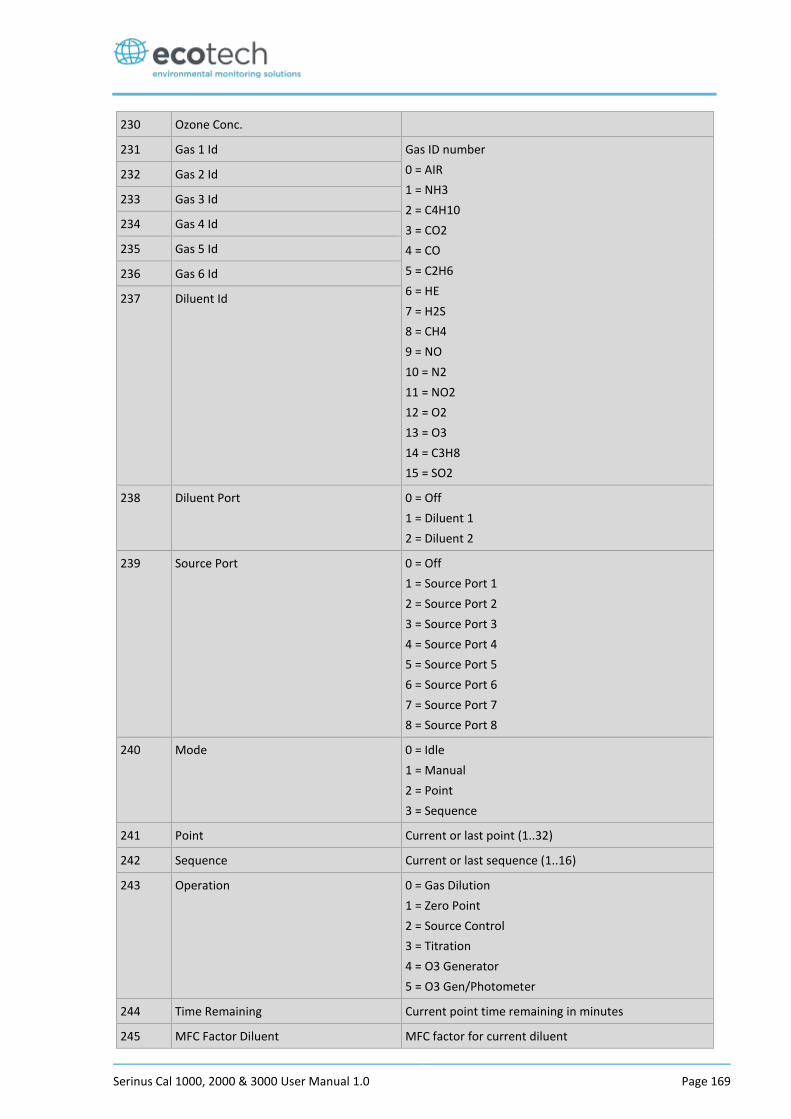
Serinus Cal 1000, 2000 & 3000 User Manual 1.0 Page 169
230 Ozone Conc.
231 Gas 1 Id Gas ID number
0 = AIR
1 = NH3
2 = C4H10
3 = CO2
4 = CO
5 = C2H6
6 = HE
7 = H2S
8 = CH4
9 = NO
10 = N2
11 = NO2
12 = O2
13 = O3
14 = C3H8
15 = SO2
232 Gas 2 Id
233 Gas 3 Id
234 Gas 4 Id
235 Gas 5 Id
236 Gas 6 Id
237 Diluent Id
238 Diluent Port 0 = Off
1 = Diluent 1
2 = Diluent 2
239 Source Port 0 = Off
1 = Source Port 1
2 = Source Port 2
3 = Source Port 3
4 = Source Port 4
5 = Source Port 5
6 = Source Port 6
7 = Source Port 7
8 = Source Port 8
240 Mode 0 = Idle
1 = Manual
2 = Point
3 = Sequence
241 Point Current or last point (1..32)
242 Sequence Current or last sequence (1..16)
243 Operation 0 = Gas Dilution
1 = Zero Point
2 = Source Control
3 = Titration
4 = O3 Generator
5 = O3 Gen/Photometer
244 Time Remaining Current point time remaining in minutes
245 MFC Factor Diluent MFC factor for current diluent
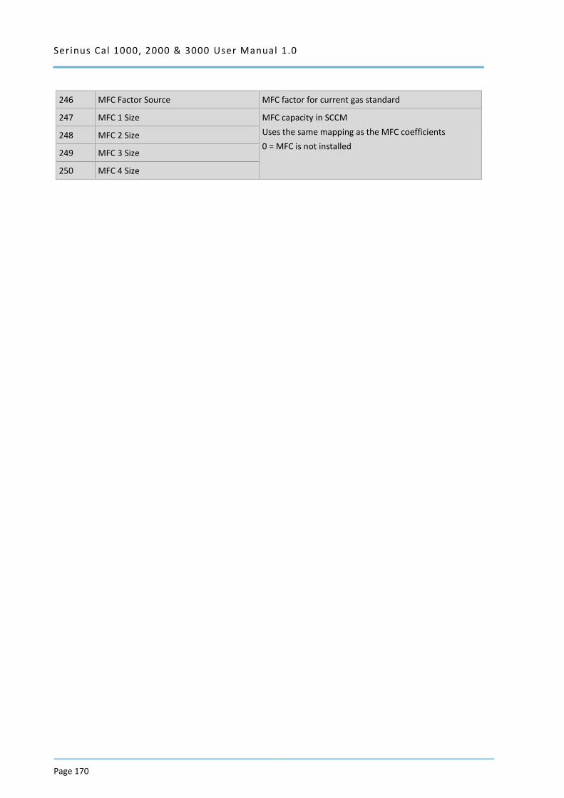
Serinus Cal 1000, 2000 & 3000 User Manual 1.0
Page 170
246 MFC Factor Source MFC factor for current gas standard
247 MFC 1 Size MFC capacity in SCCM
Uses the same mapping as the MFC coefficients
0 = MFC is not installed 248 MFC 2 Size
249 MFC 3 Size
250 MFC 4 Size
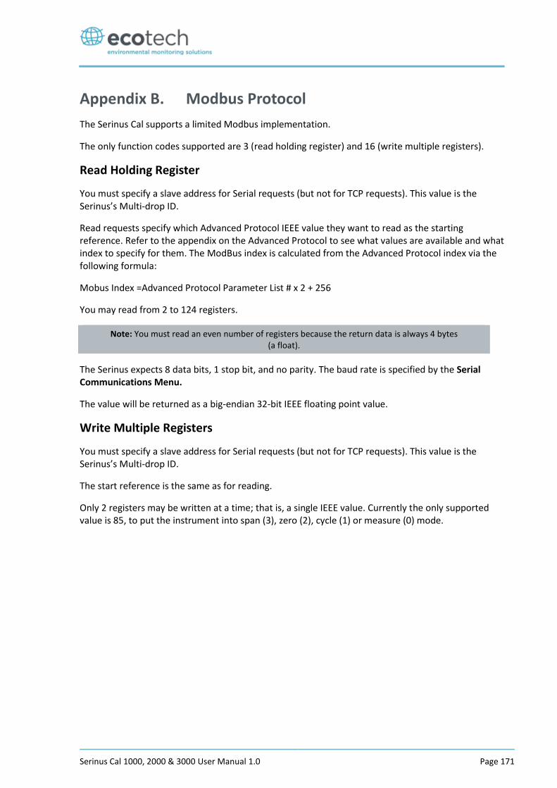
Serinus Cal 1000, 2000 & 3000 User Manual 1.0 Page 171
Appendix B. Modbus Protocol
The Serinus Cal supports a limited Modbus implementation.
The only function codes supported are 3 (read holding register) and 16 (write multiple registers).
Read Holding Register
You must specify a slave address for Serial requests (but not for TCP requests). This value is the Serinus’s Multi-drop ID.
Read requests specify which Advanced Protocol IEEE value they want to read as the starting reference. Refer to the appendix on the Advanced Protocol to see what values are available and what index to specify for them. The ModBus index is calculated from the Advanced Protocol index via the following formula:
Mobus Index =Advanced Protocol Parameter List # x 2 + 256
You may read from 2 to 124 registers.
Note: You must read an even number of registers because the return data is always 4 bytes (a float).
The Serinus expects 8 data bits, 1 stop bit, and no parity. The baud rate is specified by the Serial Communications Menu.
The value will be returned as a big-endian 32-bit IEEE floating point value.
Write Multiple Registers
You must specify a slave address for Serial requests (but not for TCP requests). This value is the Serinus’s Multi-drop ID.
The start reference is the same as for reading.
Only 2 registers may be written at a time; that is, a single IEEE value. Currently the only supported value is 85, to put the instrument into span (3), zero (2), cycle (1) or measure (0) mode.

Serinus Cal 1000, 2000 & 3000 User Manual 1.0
Page 172
Appendix C. Gascal Protocol
The Serinus Cal has a number of in built serial functions that will respond when interrogated. All commands are prefixed by a digit 0…7 corresponding to the Serial ID (see Serial Communications Menu, Section 3.5.36). This system allows multiple Serinus Cals to be connected to and controlled by the same DTE controller.
Note: All commands are in upper case. In this list, lower-case letters are placeholders, e.g., “n” refers to a single digit number, “nn” refers to a two-digit number (preceded by 0 if necessary), “nnn” refers to an integer of any
length, and “n.n” and “c0,c1,c2” refer to floating point numbers of any length.
All commands sent to the Serinus Cal must terminate with a carriage return (CR). Unless otherwise stated, all responses sent from the Serinus Cal conclude with a carriage return and line feed (CR LF).
Table 14 – Native Serial Commands
Command Description Response
iMFCn? Outputs polynomial coefficients for MFC n=1..4, where result = c2*v^2 + c1*v + c0
1 = Diluent
2 = Optional Diluent
3 = Source
4 = Optional Source
c0,c1,c2
iMFCn=c0,c1,c2 Inputs polynomial coefficients for MFC n=1..4
1 = Diluent
2 = Optional Diluent
3 = Source
4 = Optional Source
OK
iSETFLOWn= Sets flow for MFC n=1..4
1 = Diluent
2 = Optional Diluent (Note: on the Gas Cal this set the flow for ozone production; on the Serinus cal that is the same as setting the Diluent)
3 = Source
4 = Optional Source
OK
PURGE TIME? Returns purge time in seconds nnn
PURGE TIME=time Sets purge time in seconds OK
iMANUAL=ON Turns on Manual mode. This will begin running the last point loaded with iSETPOINT.
OK
iMANUAL=OFF Turns off Manual mode (selects Idle mode) OK
iT? Outputs manual timeout (minutes) nnn
iT=nnn Inputs manual timeout (minutes) OK
iSETPOINTnn Makes point nn the current point (i.e., loads its parameters into the Manual operation screen).
OK
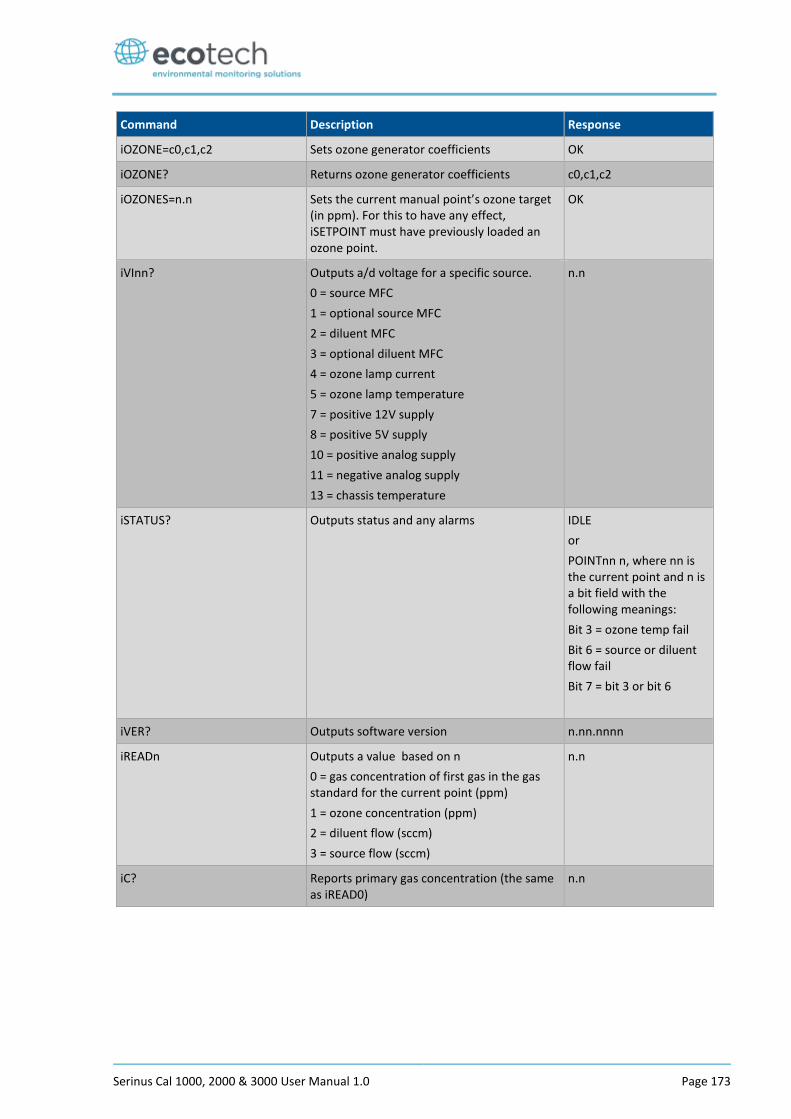
Serinus Cal 1000, 2000 & 3000 User Manual 1.0 Page 173
Command Description Response
iOZONE=c0,c1,c2 Sets ozone generator coefficients OK
iOZONE? Returns ozone generator coefficients c0,c1,c2
iOZONES=n.n Sets the current manual point’s ozone target (in ppm). For this to have any effect, iSETPOINT must have previously loaded an ozone point.
OK
iVInn? Outputs a/d voltage for a specific source.
0 = source MFC
1 = optional source MFC
2 = diluent MFC
3 = optional diluent MFC
4 = ozone lamp current
5 = ozone lamp temperature
7 = positive 12V supply
8 = positive 5V supply
10 = positive analog supply
11 = negative analog supply
13 = chassis temperature
n.n
iSTATUS? Outputs status and any alarms IDLE
or
POINTnn n, where nn is the current point and n is a bit field with the following meanings:
Bit 3 = ozone temp fail
Bit 6 = source or diluent flow fail
Bit 7 = bit 3 or bit 6
iVER? Outputs software version n.nn.nnnn
iREADn Outputs a value based on n
0 = gas concentration of first gas in the gas standard for the current point (ppm)
1 = ozone concentration (ppm)
2 = diluent flow (sccm)
3 = source flow (sccm)
n.n
iC? Reports primary gas concentration (the same as iREAD0)
n.n
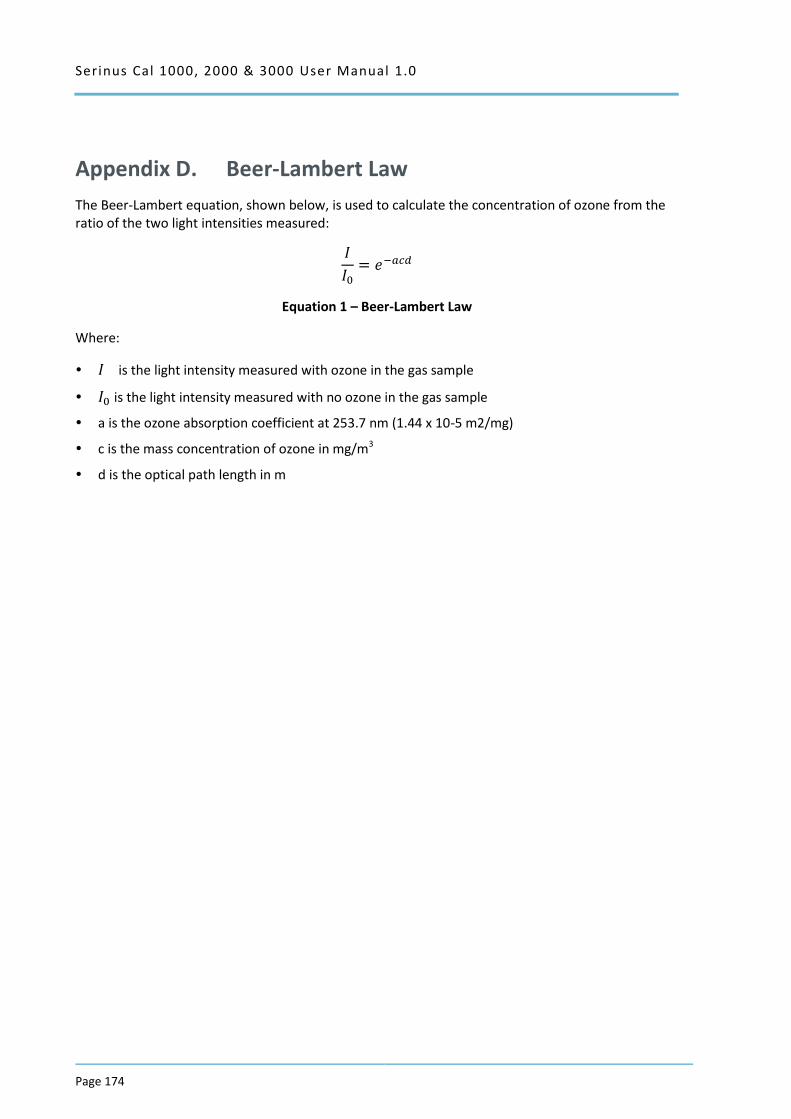
Serinus Cal 1000, 2000 & 3000 User Manual 1.0
Page 174
Appendix D. Beer-Lambert Law
The Beer-Lambert equation, shown below, is used to calculate the concentration of ozone from the ratio of the two light intensities measured:
𝐼
𝐼0= 𝑒−𝑎𝑐𝑑
Equation 1 – Beer-Lambert Law
Where:
𝐼 is the light intensity measured with ozone in the gas sample
𝐼0 is the light intensity measured with no ozone in the gas sample
a is the ozone absorption coefficient at 253.7 nm (1.44 x 10⁻⁵ m2/mg)
c is the mass concentration of ozone in mg/m3
d is the optical path length in m

Serinus Cal 1000, 2000 & 3000 User Manual 1.0 Page 175
1492 Ferntree Gully Road, Knoxfield VIC Australia 3180 Phone: +61 (0)3 9730 7800
Fax: +61 (0)3 9730 7899 Email: [email protected]
International support: [email protected]