series voltage compensation using upqc for dfig wind ... · the dfig is an induction machine with a...
TRANSCRIPT

International Journal of Modern Engineering Research (IJMER)
www.ijmer.com Vol.2, Issue.3, May-June 2012 pp-840-848 ISSN: 2249-6645
www.ijmer.com 840 | Page
P. Ramya krishna, R. B. R. Prakash2
*(EEE Department,KL University , INDIA)
** (EEE Department , KL University, INDIA
Abstract:
This paper describes the problem of voltage
sags and swells and its severe impact on sensitive loads
and introduces a new solution for doubly fed induction
generators to stay connected to the grid during voltage
sags. The main idea is to increase the stator voltage to a
level that creates the required flux to keep the rotor side
converter current below its transient rating. To
accomplish this goal, a series compensator (UPQC) is
added to inject voltage in series to the stator side line.
The series converter monitors the grid voltage and
provides compensation accordingly to accomplish this
aim. To keep the current at its minimum, a control
strategy has been developed to keep the injected voltage
and line voltage in phase during and after the fault.
Comprehensive results are presented to assess the
performance of each device as a potential custom power
solution.
Index terms: Doubly fed induction generator (DFIG),
grid fault, low-voltage ride through, series voltage
compensation, DVR, UPQC.
1. Introduction The DFIG is an induction machine with a wound rotor
where the rotor and stator are both connected to electrical
sources, hence the term „doubly fed‟. The rotor has three
phase windings which are energised with three-phase
currents. These rotor currents establish the rotor magnetic
field. The rotor magnetic field interacts with the stator
magnetic field to develop torque. The magnitude of the torque depends on the strength of the two fields (the stator
field and the rotor field) and the angular displacement
between the two fields.
The DFIG system therefore operates in both sub- and
super synchronous modes with a rotor speed range around
the synchronous speed. The stator circuit is directly
connected to the grid while the rotor winding is connected
via slip rings to a three-phase converter. For variable-speed
systems where the speed range requirements are small, for example ±30% of synchronous speed, the DFIG offers
adequate performance and is sufficient for the speed range
required to exploit typical wind resources.
An easy way to protect the converter is to disconnect
the generator during low-voltage conditions. But many
regulations have been developed and are under
development to support the grid during short circuits with
reactive power and prevent disconnection to deliver power
when the voltage is restored. Recently, many researchers
have focused on different techniques to overcome the low-
voltage ride-through (LVRT) issue. There are many different methods to mitigate
voltage sags and swells, but the use of a custom Power
device is considered to be the most efficient method.
Switching off a large inductive load or Energizing a large
capacitor bank is a typical system event that causes swells
[1].
When short circuit occurs on the grid side, the rotor
currents rise and if the converter is not protected against
these high currents, it will be damaged. The system has two
modes of operation which are: the series voltage
compensation using DVR. In this mode of operation, the voltage sags are mitigated but not completely. So in this
proposed solution, the system using UPQC for series
voltage compensation. In this method the voltage sags are
completely mitigated. The use of the Clarke transform, the
real (Ids) and imaginary (Iqs) currents can be identified.
The Park transform can be used to realize the
transformation of the Ids and the Iqs currents from the
stationary to the moving reference frame and control the
spatial relationship between the stator vector current and
rotor flux vector.
Series Voltage Compensation Using UPQC For DFIG Wind
Turbine Low-Voltage Ride-Through Solution
International Journal of Modern Engineering Research (IJMER)
www.ijmer.com Vol.2, Issue.3, May-June 2012 pp-840-848 ISSN: 2249-6645
www.ijmer.com 841 | Page
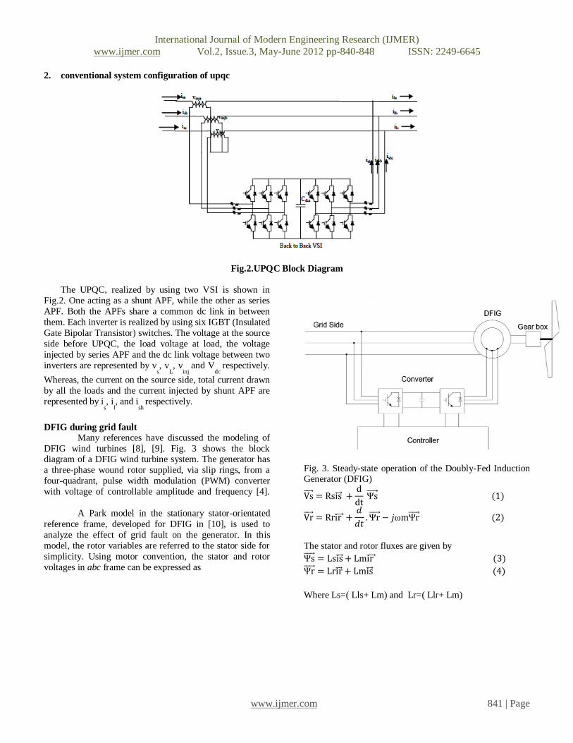
2. conventional system configuration of upqc
Fig.2.UPQC Block Diagram
The UPQC, realized by using two VSI is shown in
Fig.2. One acting as a shunt APF, while the other as series
APF. Both the APFs share a common dc link in between
them. Each inverter is realized by using six IGBT (Insulated
Gate Bipolar Transistor) switches. The voltage at the source
side before UPQC, the load voltage at load, the voltage
injected by series APF and the dc link voltage between two
inverters are represented by vs, v
L, v
inj and V
dc respectively.
Whereas, the current on the source side, total current drawn
by all the loads and the current injected by shunt APF are
represented by is, i
l, and i
sh respectively.
DFIG during grid fault
Many references have discussed the modeling of
DFIG wind turbines [8], [9]. Fig. 3 shows the block diagram of a DFIG wind turbine system. The generator has
a three-phase wound rotor supplied, via slip rings, from a
four-quadrant, pulse width modulation (PWM) converter
with voltage of controllable amplitude and frequency [4].
A Park model in the stationary stator-orientated
reference frame, developed for DFIG in [10], is used to
analyze the effect of grid fault on the generator. In this
model, the rotor variables are referred to the stator side for
simplicity. Using motor convention, the stator and rotor
voltages in abc frame can be expressed as
Fig. 3. Steady-state operation of the Doubly-Fed Induction Generator (DFIG)
Vs = Rsis +d
dt Ψs (1)
Vr = Rrir +𝑑
𝑑𝑡. Ψr − 𝑗ωmΨr (2)
The stator and rotor fluxes are given by
Ψs = Lsis + Lmir (3)
Ψr = Lrir + Lmis (4)
Where Ls=( Lls+ Lm) and Lr=( Llr+ Lm)
International Journal of Modern Engineering Research (IJMER)
www.ijmer.com Vol.2, Issue.3, May-June 2012 pp-840-848 ISSN: 2249-6645
www.ijmer.com 842 | Page
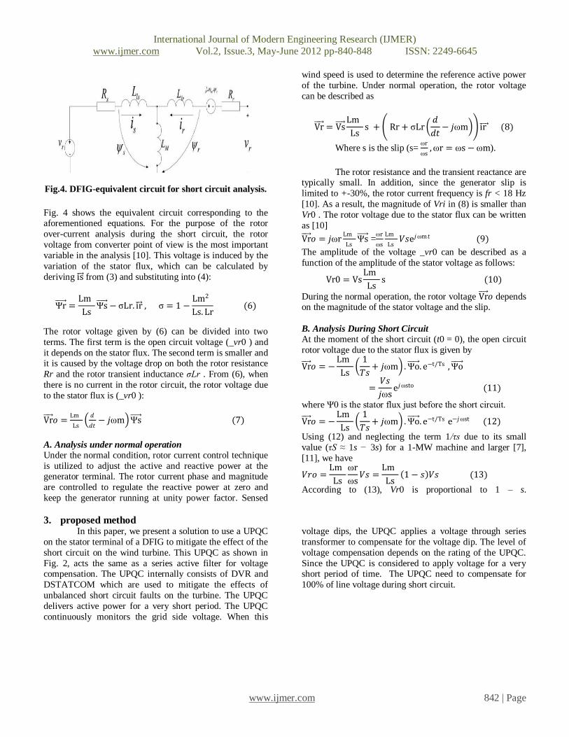
Fig.4. DFIG-equivalent circuit for short circuit analysis.
Fig. 4 shows the equivalent circuit corresponding to the aforementioned equations. For the purpose of the rotor
over-current analysis during the short circuit, the rotor
voltage from converter point of view is the most important
variable in the analysis [10]. This voltage is induced by the
variation of the stator flux, which can be calculated by
deriving is from (3) and substituting into (4):
Ψr =Lm
LsΨs − σLr. ir , σ = 1 −
Lm2
Ls. Lr (6)
The rotor voltage given by (6) can be divided into two
terms. The first term is the open circuit voltage (_vr0 ) and
it depends on the stator flux. The second term is smaller and it is caused by the voltage drop on both the rotor resistance
Rr and the rotor transient inductance σLr . From (6), when
there is no current in the rotor circuit, the rotor voltage due
to the stator flux is (_vr0 ):
Vr 𝑜 =Lm
Ls
𝑑
𝑑𝑡− 𝑗ωm Ψs (7)
A. Analysis under normal operation Under the normal condition, rotor current control technique
is utilized to adjust the active and reactive power at the generator terminal. The rotor current phase and magnitude
are controlled to regulate the reactive power at zero and
keep the generator running at unity power factor. Sensed
wind speed is used to determine the reference active power
of the turbine. Under normal operation, the rotor voltage
can be described as
Vr = Vs Lm
Lss + Rr + σLr
𝑑
𝑑𝑡− 𝑗ωm ir (8)
Where s is the slip (s= ωr
ωs, ωr = ωs − ωm).
The rotor resistance and the transient reactance are typically small. In addition, since the generator slip is
limited to +-30%, the rotor current frequency is fr < 18 Hz
[10]. As a result, the magnitude of Vri in (8) is smaller than
Vr0 . The rotor voltage due to the stator flux can be written
as [10]
Vr 𝑜 = 𝑗ωrLm
LsΨs =
ωr
ωs
Lm
Ls𝑉𝑠e𝑗ωm𝑡 (9)
The amplitude of the voltage _vr0 can be described as a
function of the amplitude of the stator voltage as follows:
Vr0 = VsLm
Lss (10)
During the normal operation, the rotor voltage Vr 𝑜 depends on the magnitude of the stator voltage and the slip.
B. Analysis During Short Circuit
At the moment of the short circuit (t0 = 0), the open circuit
rotor voltage due to the stator flux is given by
Vr 𝑜 = −Lm
Ls
1
𝑇𝑠+ 𝑗ωm . Ψo . e−t/Ts , Ψo
=𝑉𝑠
𝑗ωse𝑗ωsto (11)
where Ψ0 is the stator flux just before the short circuit.
Vr 𝑜 = −Lm
Ls
1
𝑇𝑠+ 𝑗ωm . Ψo . e−t/Ts e−𝑗ωst (12)
Using (12) and neglecting the term 1/τs due to its small
value (τS ≈ 1s − 3s) for a 1-MW machine and larger [7],
[11], we have
𝑉𝑟𝑜 =Lm
Ls
ωr
ωs𝑉𝑠 =
Lm
Ls 1 − 𝑠 𝑉𝑠 (13)
According to (13), Vr0 is proportional to 1 – s.
3. proposed method In this paper, we present a solution to use a UPQC
on the stator terminal of a DFIG to mitigate the effect of the
short circuit on the wind turbine. This UPQC as shown in
Fig. 2, acts the same as a series active filter for voltage compensation. The UPQC internally consists of DVR and
DSTATCOM which are used to mitigate the effects of
unbalanced short circuit faults on the turbine. The UPQC
delivers active power for a very short period. The UPQC
continuously monitors the grid side voltage. When this
voltage dips, the UPQC applies a voltage through series
transformer to compensate for the voltage dip. The level of
voltage compensation depends on the rating of the UPQC.
Since the UPQC is considered to apply voltage for a very short period of time. The UPQC need to compensate for
100% of line voltage during short circuit.
International Journal of Modern Engineering Research (IJMER)
www.ijmer.com Vol.2, Issue.3, May-June 2012 pp-840-848 ISSN: 2249-6645
www.ijmer.com 843 | Page
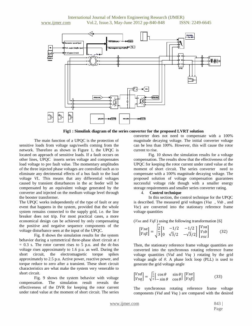
Fig1 : Simulink diagram of the series converter for the proposed LVRT solution
The main function of a UPQC is the protection of
sensitive loads from voltage sags/swells coming from the
network. Therefore as shown in Figure 1, the UPQC is
located on approach of sensitive loads. If a fault occurs on other lines, UPQC inserts series voltage and compensates
load voltage to pre fault value. The momentary amplitudes
of the three injected phase voltages are controlled such as to
eliminate any detrimental effects of a bus fault to the load
voltage VL. This means that any differential voltages
caused by transient disturbances in the ac feeder will be
compensated by an equivalent voltage generated by the
converter and injected on the medium voltage level through
the booster transformer.
The UPQC works independently of the type of fault or any
event that happens in the system, provided that the whole
system remains connected to the supply grid, i.e. the line breaker does not trip. For most practical cases, a more
economical design can be achieved by only compensating
the positive and negative sequence components of the
voltage disturbance seen at the input of the UPQC.
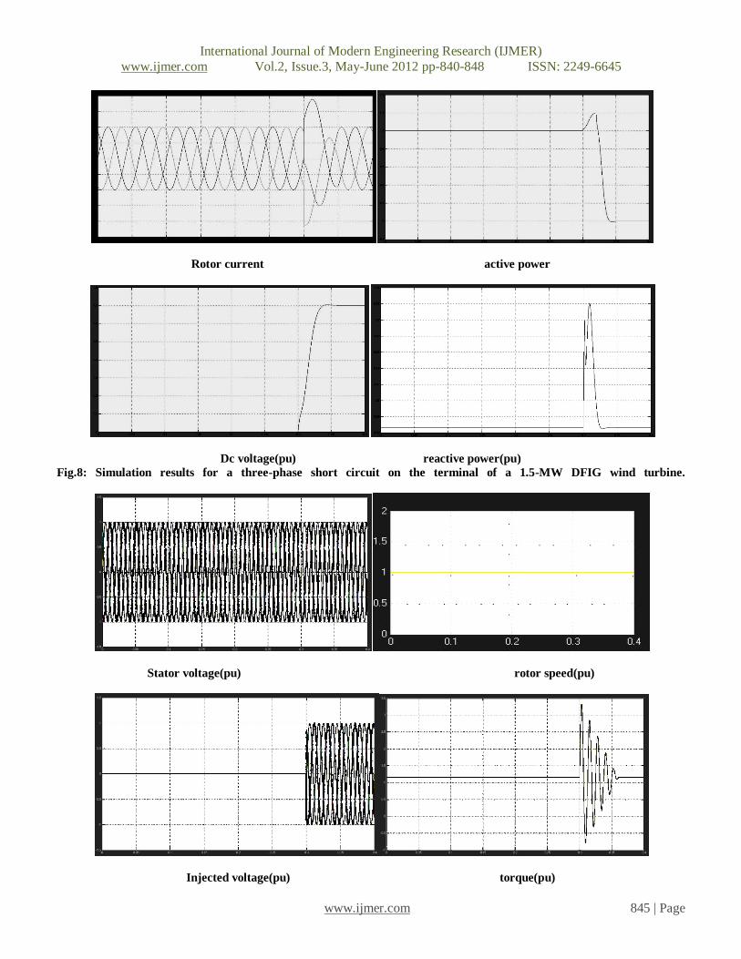
Fig. 8 shows the simulation results for the system
behavior during a symmetrical three-phase short circuit at t
= 0.3 s. The rotor current rises to 5 p.u. and the dc-bus
voltage rises approximately to 1.6 p.u. as well. During the
short circuit, the electromagnetic torque spikes
approximately to 2.5 p.u. Active power, reactive power, and
torque reduce to zero after a transient. These short circuit characteristics are what make the system very venerable to
short circuit.
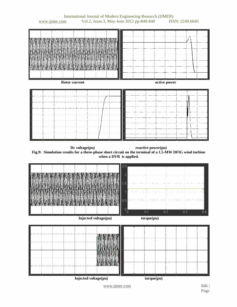
Fig. 9 shows the system behavior with voltage
compensation. The simulation result reveals the
effectiveness of the DVR for keeping the rotor current
under rated value at the moment of short circuit. The series
converter does not need to compensate with a 100%
magnitude decaying voltage. The initial converter voltage
can be less than 100%. However, this will cause the rotor
current to rise.
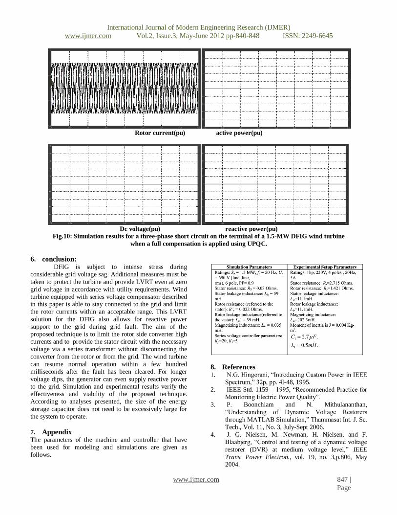
Fig. 10 shows the simulation results for a voltage compensation. The results show that the effectiveness of the
UPQC for keeping the rotor current under rated value at the
moment of short circuit. The series converter need to
compensate with a 100% magnitude decaying voltage. The
proposed solution of voltage compensation guarantees
successful voltage ride though with a smaller energy
storage requirements and smaller series converter rating.
4. Control technique In this section, the control technique for the UPQC
is described. The measured grid voltages (Vsa , Vsb , and
Vsc) are converted into the stationary reference frame
voltage quantities
(Vsα and Vsβ ) using the following transformation [6]
𝑉𝑠𝛼𝑉𝑠𝛽
= 2
3 1 −1/2 −1/2
0 3/2 − 3/2
𝑉𝑠𝑎𝑉𝑠𝑏𝑣𝑠𝑐
(32)
Then, the stationary reference frame voltage quantities are
converted into the synchronous rotating reference frame
voltage quantities (Vsd and Vsq ) rotating by the grid
voltage angle of θ. A phase lock loop (PLL) is used to
generate the grid voltage angle
𝑉𝑠𝑑𝑉𝑠𝑞
= 2
3
cos𝜃 sin 𝜃− sin 𝜃 cos𝜃
𝑉𝑠𝛼𝑉𝑠𝛽
(33)
The synchronous rotating reference frame voltage
components (Vsd and Vsq ) are compared with the desired

International Journal of Modern Engineering Research (IJMER)
www.ijmer.com Vol.2, Issue.3, May-June 2012 pp-840-848 ISSN: 2249-6645
www.ijmer.com 844 | Page
voltage to produce the reference voltage for voltage
regulator as shown in Fig. 11. During normal operation, the
compensator is not injecting any voltage. In this case, if the
capacitor is charged at its predetermined voltage, the
compensator operates at standby mode. Otherwise, it will
charge the capacitor from the line.
Fig. 11. Block diagram of the converter control technique.
5. simulation results:
Stator voltage(pu) rotor speed(pu)
Injected voltage(pu) torque(pu)
International Journal of Modern Engineering Research (IJMER)
www.ijmer.com Vol.2, Issue.3, May-June 2012 pp-840-848 ISSN: 2249-6645
www.ijmer.com 845 | Page
Rotor current active power
Dc voltage(pu) reactive power(pu)
Fig.8: Simulation results for a three-phase short circuit on the terminal of a 1.5-MW DFIG wind turbine.
Stator voltage(pu) rotor speed(pu)
Injected voltage(pu) torque(pu)
International Journal of Modern Engineering Research (IJMER)
www.ijmer.com Vol.2, Issue.3, May-June 2012 pp-840-848 ISSN: 2249-6645
www.ijmer.com 846 | Page
Rotor current active power
Dc voltage(pu) reactive power(pu)
Fig.9: Simulation results for a three-phase short circuit on the terminal of a 1.5-MW DFIG wind turbine
when a DVR is applied.
Injected voltage(pu) torque(pu)
Injected voltage(pu) torque(pu)
International Journal of Modern Engineering Research (IJMER)
www.ijmer.com Vol.2, Issue.3, May-June 2012 pp-840-848 ISSN: 2249-6645
www.ijmer.com 847 | Page
Rotor current(pu) active power(pu)
Dc voltage(pu) reactive power(pu)
Fig.10: Simulation results for a three-phase short circuit on the terminal of a 1.5-MW DFIG wind turbine
when a full compensation is applied using UPQC.
6. conclusion: DFIG is subject to intense stress during
considerable grid voltage sag. Additional measures must be
taken to protect the turbine and provide LVRT even at zero
grid voltage in accordance with utility requirements. Wind
turbine equipped with series voltage compensator described in this paper is able to stay connected to the grid and limit
the rotor currents within an acceptable range. This LVRT
solution for the DFIG also allows for reactive power
support to the grid during grid fault. The aim of the
proposed technique is to limit the rotor side converter high
currents and to provide the stator circuit with the necessary
voltage via a series transformer without disconnecting the
converter from the rotor or from the grid. The wind turbine
can resume normal operation within a few hundred
milliseconds after the fault has been cleared. For longer
voltage dips, the generator can even supply reactive power
to the grid. Simulation and experimental results verify the effectiveness and viability of the proposed technique.
According to analyses presented, the size of the energy
storage capacitor does not need to be excessively large for
the system to operate.
7. Appendix
The parameters of the machine and controller that have
been used for modeling and simulations are given as
follows.
8. References 1. N.G. Hingorani, “Introducing Custom Power in IEEE
Spectrum,” 32p, pp. 4l-48, 1995.
2. IEEE Std. 1159 – 1995, “Recommended Practice for
Monitoring Electric Power Quality”.
3. P. Boonchiam and N. Mithulananthan,
“Understanding of Dynamic Voltage Restorers
through MATLAB Simulation,” Thammasat Int. J. Sc.
Tech., Vol. 11, No. 3, July-Sept 2006.
4. J. G. Nielsen, M. Newman, H. Nielsen, and F.
Blaabjerg, “Control and testing of a dynamic voltage
restorer (DVR) at medium voltage level,” IEEE
Trans. Power Electron., vol. 19, no. 3,p.806, May 2004.

International Journal of Modern Engineering Research (IJMER)
www.ijmer.com Vol.2, Issue.3, May-June 2012 pp-840-848 ISSN: 2249-6645
www.ijmer.com 848 | Page
5. A. Ghosh and G. Ledwich, “Power Quality
Enhancement Using Custom Power Devices,” Kluwer
Academic Publishers, 2002.
6. S. Chen, G. Joos, L. Lopes, and W. Guo, "A
nonlinear control method of dynamic voltage
restorers," in 2002 IEEE 33rd Annual Power
Electronics Specialists Conference, 2002, pp. 88- 93.
7. R. Buxton, "Protection from voltage dips with the
dynamic voltage restorer," in IEE Half Day
Colloquium on Dynamic Voltage Restorers – Replacing Those Missing Cycles, 1998, pp. 3/1- 3/6.
8. H. Awad, J.Svensson, M. Bollen, “Mitigation of
Unbalanced Voltage Dips Using Static Series
Compensator”, IEEE Trans. On Power Elec., Vol. 19,
No. 13, May 2004
9. B. Singh, A. Adya, J. Gupta, “Power Quality
Enhancement with DSTATCOM for small Isolated
Alternator feeding Distribution System” Power
Electronics, And Drive System 2005, (PEDS 2005),
Vol1., 16-18 Jan Pages: 274-279
10. C. Hochgraf, R. Lasseter, “Stacom controls for
Operation with Unbalanced Voltages “ IEEE Trans. On Power delivery, Vol. 13, No. 2, April 1998.