series variation joint / tube - bibus variation joint / tube miniature joint f series miniature type...
TRANSCRIPT

934
Seriesvariation Joint / tube
Miniature jointF Series
Miniature typeBarbed, clamp joint
Jointmini-typeGWJ Series
Push-in jointFor R screw, standard sealant is applied.Flame resistance resin is provided as standard.
JointGW Series
Push-in jointFor R screw, standard sealant is applied.
Female jointMJ/JL Series
Push-in joints for fiber tube standard typePG Series
Tightening jointCan be used for copper tube.
Push-in jointPP resin incorporated as standard to increase corrosion resistance
Joint stainless steel typeZW Series
Push-in jointFlame resistance resinStainless steel material combination
Female joint stainless steel typeZJ Series
Easy Fit mechanism, tightening jointStainless steel material
Model / product appearance Feature Applicablebore size
Page Port size
M3 M5 1/8 1/4 3/8 1/2
Joint
940
948
962
968
972
978
9901.8
3.2
4
6
3.2
4
6
8
10
12
16
3.2
4
6
4
6
8
10
12
4
6
8
10
12
4
6
8
10
12
15
Refrigerating type dryer
Desiccant type dryer
High polymer membrane dryer
Auto. drain/ others
F.R.L.(Module unit)
F.R.L.(Separate)
F.R.L.(Related products)
CleanF.R.
Airbooster
Speed control valve
Check valve/ others
Joint/ tube
Suction plate
Magnetic spring buffer
Mechanical pressure SW
Electronic pressure SW
Contact / close contact conf.SW
Small flow controller
Small flow sensor
Flow sensorfor air
Flow sensor for water
Total air systemTotal air system(Gamma)
Air filter
Precise regulator
Electro pneumatic regulator
Silencer
Vacuum regulator
Air sensor
Pressure SWfor coolant
Ending
Compact F.R.
Vacuum filter

935
Join
t/tub
e
Refrigerating type dryer
Desiccant type dryer
High polymer membrane dryer
Auto. drain/ others
F.R.L.(Module unit)
F.R.L.(Separate)
F.R.L.(Related products)
CleanF.R.
Airbooster
Speed control valve
Check valve/ others
Joint/ tube
Suction plate
Magnetic spring buffer
Mechanical pressure SW
Electronic pressure SW
Contact / close contact conf.SW
Small flow controller
Small flow sensor
Flow sensorfor air
Flow sensor for water
Total air systemTotal air system(Gamma)
Air filter
Precise regulator
Electro pneumatic regulator
Silencer
Vacuum regulator
Air sensor
Pressure SWfor coolant
Ending
Compact F.R.
Vacuum filter
Durable and flexible due to high mechanical strength.
This is a coiling extensible tube.
Flame retardant material used epoch-making tube. When welding spark, etc., contact, tube does not last burning.
Model Feature Page Tube outer diameter
3.2 1.8 4 6 8 10 12 15 16
Fiber tube antistatic type
Antistatic tube
Soft nylon tube
Urethane tube
Urethane tube
Coiling tube
Flame resistant tube
Tube
1007
986
986
1001
1013
1016
1017
1018
1018
1019
Push-in joints for fiber tubeclean typeCG Series
Push-in jointPP resin incorporated as standard to increase corrosion resistance
Model / product appearance Feature Applicablebore size
Page Port size
M3 M5
1.8
Push-in joints for fiber tubeflame resistant typeRG Series
Push-in jointFlame resistance resin is provided.Ozone resistance material at packing seal section is provided as standard.
1.8
Dedicated joint for fiber tubePTN* Series
With retainer collar
1.8
1/8 1/4 3/8 1/2
994
1000
1006
Fiber tube antistatic type(Push-in joint)
Fiber tube clean type(Push-in joint)
Fiber tube flame resistant type(Push-in joint)
Extremely fine air tube as fine and flexible as lead wire. Appropriate where difficult to pipe or short piping such as narrow and tiny space, etc.
High corrosion resistant materials (special polyolefin) incorporated for use in cleanrooms. Ideal for fields a requiring clean environment, including semiconductor manufacturing, medicine, and foodstuff manufacturers.
Push-in joint tubing using flame-resistant materials. Suitable for piping in narrow space while maintaining flexibility.
This extremely fine air tubing has thinness and flexibility equivalent to a lead wire. Outstanding flexibility and high piping freedom enable piping in difficult places such as small spaces.
This tubing prevents electrostatic discharge and dust from accumulating. Outstanding flexibility and high piping freedom enable piping in difficult places such as small spaces.
Very flexible comparing to conventional nylon tube. Appropriate for piping in limited space or complicated piping.
Due to new manufacturing process, as same outer diameter as it was, while larger inner diameter and increased strength are realized. This piping tube is also used for larger than flow rate.
Joint/tubeSeries variation

936
Use the product within specifications.Using this product with fluid other than compressed air orat a pressure or temperature exceeding the specificationscould result in rupture, the tube coming off, or leakage.
Avoid installing this product outdoors or where it isexposed to direct sunlight.
Do not use the normal joint if electrostatic discharge could buildup. Otherwise system faults or failure could occur. An antistaticjoint and antistatic tubing should be used in such a case.
Design & Selection
Confirm that the product will withstand the workingenvironment.
Such environments include high temperatures, a chemicalatmosphere, or where chemicals, vibration, moisture, wa-ter drip, or gas are present; Outdoors or where the productcould be subject to direct sunlight; or where cutting oil, cool-ant, or spatter could occur or where static electricity couldpose a problem.
Securely insert the tube until it contacts the joint'stube end, and check that it does not come off thejoint.
Before replacing tubing, stop the air flow and con-firm that no pressure remains.
Installation & Adjustment
WARNING
Piping
CAUTION
WARNING
CAUTION
Pneumatic components (joint / tube)
Safety precautionsAlways read this section before starting use.Refer to Intro 67 for general precautions, and to " Safety Precautions" in this section fordetails on each series.
Confirm that PTFE can be used. The sealant contains PTFE (polytetrafluoroethylene resin)powder. Check that this poses no problem during use.
Consult with CKD if ozone could occur in suppliedair. (An ozone-resistant series is available.)
Avoid using this product in hot or humid places, orwhere it could be subject to direct sunlight. Installthis product where the temperature is 40°C or less.
Flame-resistant resin (equivalent to UL94 StandardV-O) is provided for GW Series' push ring, but not forGWJ Series. Check specifications when selecting theproduct.
+0.1-0.15
Observe the following precautions when using nylontubes or urethane tubes for piping material.
Use the designated tube and CKD plastic plug (GWP Se-ries). Do not use metal plugs.Tube outer diameter precision · Polyamide tube : Within 0.1mm · Polyurethane tube (up to 6): Within 0.1mm ( 8 to): Within mmUse a tube with a hardness of 92° or more. If a tube thatdoes not satisfy diameter accuracy or hardness is used,chucking force may drop or the tube may come off or bedifficult to insert.Consult with CKD when using a nondesignated tube or plug.
Use a flame resistant tube or metal pipe where spatter couldoccur. When using the standard push-in joint on the spiral tube,fix the base of the tube with a hose band. Rotation occurs,and holding performance is decrease. Cut the tube at right angles using a dedicated cutting tool. Do not use a worn or damaged tube that could be crushedor rupture. Do not reuse the tube, which is worn and deformed. Do not let tube directly contact other structures because itcould wear and break.
Do not use this valve for applications that constantlyrotate, vibrate or which have a tube that moves vig-orously.
The elbow type can be mounted by turning it, but must notbe used for constant rotating or oscillating applications.Otherwise the joint could be damaged. Provide sufficient allowance in the tube so that it does notbent suddenly.
Refrigerating type dryer
Desiccant type dryer
High polymer membrane dryer
Auto. drain/ others
F.R.L.(Module unit)
F.R.L.(Separate)
F.R.L.(Related products)
CleanF.R.
Airbooster
Speed control valve
Check valve/ others
Joint/ tube
Suction plate
Magnetic spring buffer
Mechanical pressure SW
Electronic pressure SW
Contact / close contact conf.SW
Small flow controller
Small flow sensor
Flow sensorfor air
Flow sensor for water
Total air systemTotal air system(Gamma)
Air filter
Precise regulator
Electro pneumatic regulator
Silencer
Vacuum regulator
Air sensor
Pressure SWfor coolant
Ending
Compact F.R.
Vacuum filter

937
Joint / tube
Join
t/tub
e
Refrigerating type dryer
Desiccant type dryer
High polymer membrane dryer
Auto. drain/ others
F.R.L.(Module unit)
F.R.L.(Separate)
F.R.L.(Related products)
CleanF.R.
Airbooster
Speed control valve
Check valve/ others
Joint/ tube
Suction plate
Magnetic spring buffer
Mechanical pressure SW
Electronic pressure SW
Contact / close contact conf.SW
Small flow controller
Small flow sensor
Flow sensorfor air
Flow sensor for water
Total air systemTotal air system(Gamma)
Air filter
Precise regulator
Electro pneumatic regulator
Silencer
Vacuum regulator
Air sensor
Pressure SWfor coolant
Ending
Compact F.R.
Vacuum filter
Check that the tool's hexagon face and wrench are the cor-rect size.
Pipe so that piping connections do not become dis-located due to device movement, vibration, or ten-sion, etc.
Control of actuator speed will be disabled if piping on theexhaust side of the pneumatic circuit is disengaged. When using the chuck holding mechanism, the chuck willbe released creating a hazardous state. Confirm that the tube has been inserted properly, and makesure that there is no tension during use.The tube could be dislocated or damaged if there is anytension.
Make sure that the joint and tube are not twisted orpulled, and that moment load is not applied.
Do not tighten while pressure is applied.
Observe the following precautions when using nylontubes or urethane tubes for piping material.
Use a flame resistant tube or metal pipe where spatter couldoccur. Use a hydraulic hose for common piping for hydraulic andpneumatic specifications. When using the standard push-in joint on the spiral tube,fix the base of the tube with a hose band. Rotation occurs,and holding performance is decrease. When using for hot liquids, use a soldered screw joint. Thepush-in join cannot be used.
Check that tubing is not worn or damaged. Tubing could be crushed, break, or be dislocated.
Use the designated tube.
Securely insert the tube to the tube end, and makesure that the tube cannot be pulled off.
Use tubing within the minimum bending radius butlong enough to avoid sharp bends.
Consider changes in tubing length caused by pressure whentubing is connected, and provide sufficient length within theminimum tube bending radius. Measuring method(1) Minimum bending radius (JIS B8381)The values are based on JIS B8381.If tubing is tightly wound around a round rod, indicate therod radius when variation reaches 25%.
(2) Minimum installation radiusTo measure, simply bend the tube and confirm the radiuswhen tube diameter deformation is 10%.
Always flush just before piping pneumatic compo-nent.
Any foreign matter that has entered during piping must beremoved so it does not enter the pneumatic component.Remove all swarf and foreign debris generated during pip-ing and tube insertion before starting use.
When supplying compressed air for the first time af-ter connecting pipes, do not apply high pressure sud-denly.
Piping connection could be dislocated or the piping tube flyoff, leading to accidents.
After connecting piping, check pipe connections forair leaks before supplying compressed air.
Apply a leakage detection agent on pipe connections witha brush, and check for air leaks.
Apply adequate torque when connecting pipes. To prevent air leak and to protect thread. Tighten by handat first so that threads are not damaged, then use a tool.
M3
M5
Rc1/8
Rc1/4
Rc3/8
Rc1/2
0.3 to 0.6
1.0 to 1.5
3 to 5
6 to 8
13 to 15
16 to 18
Tightening torque N·mPort thread
(Reference value)
* The above values apply when the mating screw is a JISB 0203 tapered female thread for piping (material: C3604BD).
L
D
Bar stock
dtube
= 1-L - D2d
x 100
: Deforming ratio (%)d : Tube outer diameter (mm)L : Measuring volume (mm)D : Round rod diameter (mm)
(Minimum bending radius of 2 time)
P
Shall be the minimum mounting pitch when the deformation rate is 10%.Min. installation radius = P/2

938
Chamfered outer diameter
Female thread side
Port thread
M3
M5
Chamfered outer diameter (mm)
3.3 to 3.9
5.4 to 5.8
45°
Do not tighten too much.
Cut the tube with a dedicated cutter, and cut at aperpendicular angle.
If the set screw is M3 or M5 screw, the chamferedouter diameter of the female thread side must bewithin the following values.
Installation & Adjustment
Except for separating the main body and nut, do notdisassemble or modify joint components. Otherwisefunctions cannot be guaranteed.
This product and nuts are made of the same mate-rial (SUS316).When tightening, stop as soon as the body and nutcome in contact.Tightening tubing too much could cause seizure atthreads, making itdifficult to removetubing.
CAUTION
Pneumatic components (joint / tube)
Safety precautionsAlways read this section before starting use.Refer to Intro 67 for general precautions, and to " Safety Precautions" in this section fordetails on each series.
ZJ Series
Keeping
ZJ Series
The joint is made of highly corrosion-resistant mate-rial, but rust could spread from another point. Avoidstoring this part with products made of other materi-als, and store in a clean, dry place.
Store this product with nuts as a set. If parts are storedseparately, the body and nut threads or body protru-sions (seals) could be damaged or connection faultsor leaks occur.
Refrigerating type dryer
Desiccant type dryer
High polymer membrane dryer
Auto. drain/ others
F.R.L.(Module unit)
F.R.L.(Separate)
F.R.L.(Related products)
CleanF.R.
Airbooster
Speed control valve
Check valve/ others
Joint/ tube
Suction plate
Magnetic spring buffer
Mechanical pressure SW
Electronic pressure SW
Contact / close contact conf.SW
Small flow controller
Small flow sensor
Flow sensorfor air
Flow sensor for water
Total air systemTotal air system(Gamma)
Air filter
Precise regulator
Electro pneumatic regulator
Silencer
Vacuum regulator
Air sensor
Pressure SWfor coolant
Ending
Compact F.R.
Vacuum filter
The effective sectional area of the turn elbow (GWL*-*-T, GWL*-*-2T) varies based on the direction.

939
Joint / tube
Join
t/tub
e
Refrigerating type dryer
Desiccant type dryer
High polymer membrane dryer
Auto. drain/ others
F.R.L.(Module unit)
F.R.L.(Separate)
F.R.L.(Related products)
CleanF.R.
Airbooster
Speed control valve
Check valve/ others
Joint/ tube
Suction plate
Magnetic spring buffer
Mechanical pressure SW
Electronic pressure SW
Contact / close contact conf.SW
Small flow controller
Small flow sensor
Flow sensorfor air
Flow sensor for water
Total air systemTotal air system(Gamma)
Air filter
Precise regulator
Electro pneumatic regulator
Silencer
Vacuum regulator
Air sensor
Pressure SWfor coolant
Ending
Compact F.R.
Vacuum filter
Installation
Tube
During Use & Maintenance
Mounting and removal
CAUTION
Push the tube in until it contacts the tube end.Check that the tube is not dislocated from the joint. Tube goesin 15 to 21mm into the end of the joint body. The end of themounted tube must be cut at a right angle.
Removal
While pushing the push ring with a finger, pull the tube toremove it.
InstallationBody Sleeve integrated nut
2
1
3
ZJ Series
Pass tubing through the sleeve integrated with the nut.Insert tubing into the main body, and tighten the sleeve inte-grated with the nut until it contacts the body.Stop tightening the sleeve integrated with the nut when thebody and nut come in contact.Tightening tubing too much could cause seizure at threads,making it difficult to remove tubing.
Removal1
2
Loosen the sleeve integrated with the nut and pull out tubing.The sleeve integrated with the nut can be reused.

940
F Miniature jointPort size M3 to 1/8 (Rc or R)
44 types of miniature joints are available with port size M3, M5, bore size 3.2, 4, 6
Barbed nipple/FTS-0 Straight/FCSBranch/FTTElbow/FTLStraight/FTS
Elbow/FSL Branch/FSTStraight/FSSStraight/FNSElbow/FCL
Deforming tee union/FAY FBSCross/FAXBranch/FATElbow/FAL
FMH sales unit: 1 pieceFMB sales unit: 1 pieceFLSFPLFWS sales unit: 5 pieces
FGS sales unit: 100 pieces
Barbed joint
Double screw nipple Socket
Clamp joint
BushAdjustable socket
Bulk head
Gasket
Plug Extension Manifold
· Applicable tube O.D.: 3.2 to 6· Page: 942
· Applicable tube O.D.: 3.2 to 6· Page: 942
· Applicable tube O.D.: 3.2 to 6· Page: 942
· Applicable tube O.D.: 3.2 to 6· Page: 942
· Applicable tube O.D.: 3.2 to 6· Page: 943
· Page: 944· Page: 944· Page: 943· Page: 943· Applicable tube O.D.: 3.2 to 6· Page: 943
· Page: 944 · Page: 944 · Page: 945 · Page: 945 · Page: 945
· Page: 945 · Page: 946 · Page: 946 · Page: 946· Page: 946
· Page: 946 If sales unit is not specified, the product is packed 10 pcs/bag.
940
Refrigerating type dryer
Desiccant type dryer
High polymer membrane dryer
Auto. drain/ others
F.R.L.(Module unit)
F.R.L.(Separate)
F.R.L.(Related products)
CleanF.R.
Airbooster
Speed control valve
Check valve/ others
Joint/ tube
Suction plate
Magnetic spring buffer
Mechanical pressure SW
Electronic pressure SW
Contact / close contact conf.SW
Small flow controller
Small flow sensor
Flow sensorfor air
Flow sensor for water
Total air systemTotal air system(Gamma)
Air filter
Precise regulator
Electro pneumatic regulator
Silencer
Vacuum regulator
Air sensor
Pressure SWfor coolant
Ending
Compact F.R.
Vacuum filter

941
Min
iatu
re jo
int
Join
t/tub
e
Refrigerating type dryer
Desiccant type dryer
High polymer membrane dryer
Auto. drain/ others
F.R.L.(Module unit)
F.R.L.(Separate)
F.R.L.(Related products)
CleanF.R.
Airbooster
Speed control valve
Check valve/ others
Joint/ tube
Suction plate
Magnetic spring buffer
Mechanical pressure SW
Electronic pressure SW
Contact / close contact conf.SW
Small flow controller
Small flow sensor
Flow sensorfor air
Flow sensor for water
Total air systemTotal air system(Gamma)
Air filter
Precise regulator
Electro pneumatic regulator
Silencer
Vacuum regulator
Air sensor
Pressure SWfor coolant
Ending
Compact F.R.
Vacuum filter
Safety Precautions
Internal structure and parts list
(1) If urethane tube is used with 40°C and over, use a clamp joint.(2) Use a nylon tube with tolerance of diameter within 0.1, while urethane rubber tube
within.(3) Type with slit on clamp ring of clamp joint is for tube O.D. 3.2mm.(4) If elbow, branch, cross, deforming branch or barbed joint is used at frequently moving
tube section, trouble may occur. So please avoid use in such place.(5) Bending radius of tube is to be the right value and over near a joint.
SpecificationsDescriptions F
Note: Use urethane tube within 0 to 60 range. (Refer to page 1012 for the dimensions of tube and working pressure. )
Compressed air
0.7 or less
-5 to 60 (no freezing)
Soft nylon tube (model no. FH-3224, F-1504, F-1506)
Urethane tube (model no. U-9504, U-9506) note
Working fluid
Max. working pressure MPa
Ambient / fluid temperature
Applicable tube
DA B CF
Miniaturejoint
How to order
D
A
B Flow path shape
C
Shape
Applicable tube O.D.
Port size
No. Part name Material treatmentBolt Brass Electroless nickeling
O ring Nitrile rubber -
Clamp ring Brass Electroless nickeling
Body Brass Electroless nickeling
Gasket Nitrile rubber, steel -
1
2
3
4
5
Minimum bending radius mm Barbed joint Clamp jointSoft nylon 20 10
Soft nylon 20 10
Urethane 20 10
Soft nylon 40 20
Urethane 40 20
3.2
4
6
Note 1: Refer to model no. sections in dimensions (pages 941 to 946)for detailed combination of model no.
Note 2: Sales unit is 10 pieces/1 bag.Refer to the system table on page 940 for model sales units.
+0.1 - 0.15
1
2
3
4
5
Figure shows FCL type.
F Series
Specifications
Ozone specifications (Ending 5)
F - ················· - P11
Clean room specifications (catalog No. CB-033SA)
F - ················· - P80

942
Dimensions: Barbed joint (straight, elbow, branch, barbed nipple)
Barbed joint Straight/FTS Elbow/FTL
Branch/FTT Barbed nipple/FTS*-0
FTS4-M3
FTS4-M5
FTS4-6
FTS6-M5
FTS6-6
Model no.
0.4
2.1
2.1
4.1
4.1
3.2, 4
3.2, 4
3.2, 4
6
6
Applicable tube O.D.
4.5
7
10
7
10
B
M3 x 0.5
M5 x 0.8
R1/8
M5 x 0.8
R1/8
E
2.9
2.9
2.9
4.7
4.7
H
5.5
5.5
5.5
7
7
J
7.9
8.6
9.5
10.1
11
K
2.6
2.9
8
2.9
8
L
0.8
1.8
1.8
2.5
2.5
Min. bore size
Effective sectional area (mm2)
FTL4-M3
FTL4-M5
FTL6-M5
Model no.
0.4
1.3
1.5
3.2, 4
3.2, 4
6
Applicable tube O.D.
10.5
13.5
15
A
5
8
8
D
M3 x 0.5
M5 x 0.8
M5 x 0.8
E
2.9
2.9
4.7
H
2.9
5.1
5.1
J
6.8
11.6
11.6
K
2.6
2.9
2.9
L
1
1.8
1.8
Min. bore size
Effective sectional area (mm2)
FTT4-M3
FTT4-M5
FTT6-M5
Model no.
0.4
1.3
1.5
3.2, 4
3.2, 4
6
Applicable tube O.D.
16
19
22
A
5
8
8
D
M3 x 0.5
M5 x 0.8
M5 x 0.8
E
2.9
2.9
4.7
H
2.9
5.1
5.1
J
6.8
11.6
11.6
K
2.6
2.9
2.9
L
1
1.8
1.8
Min. bore size
Effective sectional area (mm2)
FTS4-0
FTS6-0
Model no.
3.2, 4
6
Applicable tube O.D.
5
7
B
2.9
4.7
H
5.5
7
J
12
15
L
1.8
2.5
Min.bore size
2.1
4.1
Effective sectional area (mm2)
E
L K
J
H
B
A
J
L
HK
E
* D
A
D
E
K
H
L
J
J
H
B
J
L
F Series
Refrigerating type dryer
Desiccant type dryer
High polymer membrane dryer
Auto. drain/ others
F.R.L.(Module unit)
F.R.L.(Separate)
F.R.L.(Related products)
CleanF.R.
Airbooster
Speed control valve
Check valve/ others
Joint/ tube
Suction plate
Magnetic spring buffer
Mechanical pressure SW
Electronic pressure SW
Contact / close contact conf.SW
Small flow controller
Small flow sensor
Flow sensorfor air
Flow sensor for water
Total air systemTotal air system(Gamma)
Air filter
Precise regulator
Electro pneumatic regulator
Silencer
Vacuum regulator
Air sensor
Pressure SWfor coolant
Ending
Compact F.R.
Vacuum filter

943
Min
iatu
re jo
int
Join
t/tub
e
Refrigerating type dryer
Desiccant type dryer
High polymer membrane dryer
Auto. drain/ others
F.R.L.(Module unit)
F.R.L.(Separate)
F.R.L.(Related products)
CleanF.R.
Airbooster
Speed control valve
Check valve/ others
Joint/ tube
Suction plate
Magnetic spring buffer
Mechanical pressure SW
Electronic pressure SW
Contact / close contact conf.SW
Small flow controller
Small flow sensor
Flow sensorfor air
Flow sensor for water
Total air systemTotal air system(Gamma)
Air filter
Precise regulator
Electro pneumatic regulator
Silencer
Vacuum regulator
Air sensor
Pressure SWfor coolant
Ending
Compact F.R.
Vacuum filter
Dimensions: Clamp joint (straight, elbow), double screw nipple (straight), socket (straight)
Clamp joint Straight/FCS Elbow/FCL
Straight/FNS Straight/FSS
Double screw nipple
FCS3-M5
FCS3-6
FCS4-M5
FCS4-6
FCS6-M5
FCS6-6
Model no.
2.1
2.1
2.1
2.1
4.1
4.1
3.2
3.2
4
4
6
6
Applicabletube O.D.
7
10
7
10
8
10
B
M5 x 0.8
R1/8
M5 x 0.8
R1/8
M5 x 0.8
R1/8
E
7
7
7
7
9
9
G
4.3
4.3
4.3
4.3
5
5
I
11.7
12.1
11.7
12.1
12.4
12.8
K
2.9
8
2.9
8
2.9
8
L
1.8
1.8
1.8
1.8
2.5
2.5
Min.bore size
Effective sectionalarea (mm2)
FCL3-M5
FCL4-M5
FCL6-M5
Model no.
1.3
1.3
1.5
3.2
4
6
16.1
16.1
17.8
A
8
8
9
D
7
7
9
G
4.3
4.3
5
I
5.1
5.1
6.1
J
11.6
11.6
13.6
K
1.8
1.8
1.8
Min.bore size
Effective sectionalarea (mm2)
Applicabletube O.D.
FNS-M3
FNS-M5
Model no.
M3 x 0.5
M5 x 0.8
E
4.5
7
B
2.8
3.7
K
2.6
2.9
L
0.8
1.8
Min.bore size
0.4
2.1
Effective sectionalarea (mm2)
FSS-M3
FSS-M5
Model no.
M3 x 0.5
M5 x 0.8
E
4.5
7
B
7
8
L
4
9
Effective sectional area (mm2)
A
* D
I
M5 x 0.8
K2.
9
J
G
B
2-E
L
Min
. bor
e si
ze
KL
L B
E
Socket
F Series
Dimensions
E
G
I
K BL

944
Dimensions: Double screw nipple (elbow), socket (branch), adjustable socket (elbow, branch)
Elbow/FSL-M5
Elbow/FAL Branch/FAT
Adjustable socket
FAL-M3
FAL-M5
Model no.
M3 x 0.5
M5 x 0.8
E
2.5
4
B
5
8
D
4.5
6.5
C
2.9
5.6
J
6.8
11.6
K
2.6
2.9
L
1
1.8
Min.bore size
0.5
1.7
Effective sectionalarea (mm2)
FAT-M3
FAT-M5
Model no.
M3 x 0.5
M5 x 0.8
E
5
8
B
9
12
C
2.9
5.6
J
6.8
11.6
K
2.6
2.9
L
1
1.8
Min.bore size
0.5
1.7
Effective sectionalarea (mm2)
Double screw nipple
8
2-M5 x 0.8
5
9
6.5 6.5
8
9
5
3-M5 x 0.86.5 6.5
B C
2-E
J
KL
D C
3-E
J
KL
B
Effective sectional area 8mm2Effective sectional area 8mm2
Socket
F Series
Refrigerating type dryer
Desiccant type dryer
High polymer membrane dryer
Auto. drain/ others
F.R.L.(Module unit)
F.R.L.(Separate)
F.R.L.(Related products)
CleanF.R.
Airbooster
Speed control valve
Check valve/ others
Joint/ tube
Suction plate
Magnetic spring buffer
Mechanical pressure SW
Electronic pressure SW
Contact / close contact conf.SW
Small flow controller
Small flow sensor
Flow sensorfor air
Flow sensor for water
Total air systemTotal air system(Gamma)
Air filter
Precise regulator
Electro pneumatic regulator
Silencer
Vacuum regulator
Air sensor
Pressure SWfor coolant
Ending
Compact F.R.
Vacuum filter
Branch/FST-M5

945
Min
iatu
re jo
int
Join
t/tub
e
Refrigerating type dryer
Desiccant type dryer
High polymer membrane dryer
Auto. drain/ others
F.R.L.(Module unit)
F.R.L.(Separate)
F.R.L.(Related products)
CleanF.R.
Airbooster
Speed control valve
Check valve/ others
Joint/ tube
Suction plate
Magnetic spring buffer
Mechanical pressure SW
Electronic pressure SW
Contact / close contact conf.SW
Small flow controller
Small flow sensor
Flow sensorfor air
Flow sensor for water
Total air systemTotal air system(Gamma)
Air filter
Precise regulator
Electro pneumatic regulator
Silencer
Vacuum regulator
Air sensor
Pressure SWfor coolant
Ending
Compact F.R.
Vacuum filter
Dimensions: Adjustable socket (cross, deforming tee union), bush, bulk head
FBS FWS
Bush Bulk head
FBS-M56
FBS-M58
Model no.
R1/8
R1/4
E
10
14
B
4
5
N
12
16
L
9
9
Effective sectionalarea (mm2)
FWS-M5
FWS-M56
Model no.
M5 x 0.8
Rc1/8
E
11
16
L
14.7
15.2
D
8
12
d
4
7
N
M8 x 1
M12 x 1
O
9
9
Effective sectionalarea (mm2)
3
5
M
Adjustable socket Cross/FAX-M5 Deforming tee union/FAY-M5
812
2.9
16.6
5.6
4-M5 x 0.8
864
2.9
16.6
5.6
3-M5 x 0.8
M5 x 0.8
M5 x 0.8
M3 x 0.5
6.53.
6
7
E
N
LB
FBS-M56/M58
FBS-M3M5
O
d
D
E
N M
L
M5 x 0.8
Material SS400BD(With galvanizing)
3 (max)
Min. bore size 1.8mm
Effective sectional area 1.7mm2
Min. bore size 1.8mm
Effective sectional area 1.7mm2
Effective sectional area 4mm2
F Series
Dimensions

946
Dimensions: Plug, extension, manifold, gasket
FMH-M56
FPL FLS-M5
Plug Extension
FMB-M56
Manifold
FGS
Gasket
FGS-M3
FGS-M5
Model no.
4.8
7.8
D
2.8
4.8
d
0.4
0.6
t
B
N L
E
C
7
13.6 2-M5 x 0.82.9
6-M5
1315151515
80
452- 4.2
20.5 15
Rc1/8
5 54
177
t
D
d
Effective sectional area 2.1mm2
FPL-M3
FPL-M5
Model no.
M3 x 0.5
M5 x 0.8
E
4.5
7
B
4.9
7.8
C
2.4
3.1
N
2.6
2.9
L
F Series
14
25
36.88-M5
1111.5
42
29
5.2
44
3822.3
Rc1/819
2.3
Refrigerating type dryer
Desiccant type dryer
High polymer membrane dryer
Auto. drain/ others
F.R.L.(Module unit)
F.R.L.(Separate)
F.R.L.(Related products)
CleanF.R.
Airbooster
Speed control valve
Check valve/ others
Joint/ tube
Suction plate
Magnetic spring buffer
Mechanical pressure SW
Electronic pressure SW
Contact / close contact conf.SW
Small flow controller
Small flow sensor
Flow sensorfor air
Flow sensor for water
Total air systemTotal air system(Gamma)
Air filter
Precise regulator
Electro pneumatic regulator
Silencer
Vacuum regulator
Air sensor
Pressure SWfor coolant
Ending
Compact F.R.
Vacuum filter

948
GW JointPort size M3 to 1/2 (Rc or R)
Wide connection joints and models
Bulk head femaleGWS*-*-E
Bulk headGWS*-*-X
Female straightGWS*-*-M
Single straightGWS*-*-S
Single straightGWS*-*
Plug reducerGWS*-*P
PlugGWP*-0
Different diameter straightGWS*-0
StraightGWS*-0
Bulk head female connectorGWM*-*-X
Single 45° elbowGWL*-*-45
Turn elbow GWL*-*-T
Long elbowGWL*-*-L
Single elbowGWL*-*
Plug reducerGWP*-0
Tee unionGWT-0
Y type tee unionGWY*-0
D type tee unionGWT*-*-D
Both push-in branchGWT*-*
ElbowGWL*-0
Straight type
Tee union type
Elbow type
Applicable tubeO.D.
Applicable tubeO.D.
Applicable tubeO.D.
Applicable tubeO.D.
Applicable tubeO.D.
Applicable tubeO.D.
Applicable tubeO.D.
Applicable tubeO.D.
Applicable tubeO.D.
Applicable tubeO.D.
Applicable tubeO.D.
Applicable tubeO.D.
Applicable tubeO.D.
Applicable tubeO.D.
Applicable tubeO.D.
Applicable tubeO.D.
Applicable tubeO.D.
Applicable tubeO.D.
Applicable tubeO.D.
Applicable tubeO.D.
4
6
8
10
12
16
3.2
4
6
8
10
12
4
6
8
10
12
4
6
8
10
12
4
6
8
10
12
4
6
8
10
12
4
6
8
10
12
16
4, 6
6, 8
8, 10
10, 12
4
6
8
10
4
6
8
10
12
4, 6
6, 8
8, 10
10, 12
4
6
8
10
12
16
4
6
8
10
12
4
6
8
10
12
4
6
8
10
12
4
6
8
10
12
16
4
6
8
10
12
4
6
8
10
12
4
6
8
10
12
4, 46, 68, 8
10, 1012, 12
6, 48, 6
10, 812, 10
· Page: 952 · Page: 952 · Page: 952 · Page: 952 · Page: 953
· Page: 953 · Page: 953 · Page: 953 · Page: 954 · Page: 954
· Page: 954 · Page: 954 · Page: 955 · Page: 955 · Page: 955
· Page: 955 · Page: 956 · Page: 956 · Page: 956 · Page: 956
948 Sales unit is 10 pieces/1 box.
Refrigerating type dryer
Desiccant type dryer
High polymer membrane dryer
Auto. drain/ others
F.R.L.(Module unit)
F.R.L.(Separate)
F.R.L.(Related products)
CleanF.R.
Airbooster
Speed control valve
Check valve/ others
Joint/ tube
Suction plate
Magnetic spring buffer
Mechanical pressure SW
Electronic pressure SW
Contact / close contact conf.SW
Small flow controller
Small flow sensor
Flow sensorfor air
Flow sensor for water
Total air systemTotal air system(Gamma)
Air filter
Precise regulator
Electro pneumatic regulator
Silencer
Vacuum regulator
Air sensor
Pressure SWfor coolant
Ending
Compact F.R.
Vacuum filter

949
Tetrapod shaped (with R)GWTR*-*
FY type (with R)GWFY*-*
2 port turn elbowGWL*-*-2T
Cross shapedGWCR*-0
Both ports Y tee unionGWY*-*
Double Y typeGWWY*-0
Blanking plugGWP*-B
FY typeGWFY*-0
Tetrapod shapedGWTR*-0
Double Y type (with R)GWWY*-*
Cap GWC*
Manifold (single/with R)GWMF*-*
Y type plugGWP*-Y
C type plugGWP*-C
L type plugGWP*-L
Manifold (double solenoid)GWMF*-0-W
Manifold (double/with R)GWMF*-*-W
Manifold (single solenoid)GWMF*-0
Applicable tubeO.D.
Applicable tubeO.D.
Applicable tubeO.D.
Applicable tubeO.D.
Applicable tubeO.D.
4
6
8
10
12
8
10
12
4
6
8
10
12
4
6
8
10
12
4
6
8
10
12
4
6
4
6
8
10
12
4
6
8
10
12
6, 4
8, 6
Connecting jointDiameter
4
6
8
10
12
16
4
6
8
10
12
4
6
8
10
12
4
6
8
10
12
4
6
8
10
12
4, 6
4, 8
6, 8
6, 10
8, 10
4, 6
4, 8
6, 8
6, 10
8, 10
4, 8
6, 10
8, 12
4, 8
6, 10
8, 12
· Page: 957 · Page: 957 · Page: 957 · Page: 957 · Page: 958
· Page: 958 · Page: 958 · Page: 958 · Page: 959 · Page: 959
· Page: 959 · Page: 959 · Page: 960 · Page: 960 · Page: 960
· Page: 960
Insert ringCustom order
4
6
8
10
12· Page: 961· Page: 961 · Page: 961
Applicable tubeO.D.
Applicable tubeO.D.
Applicable tubeO.D.
Applicable tubeO.D.
Applicable tubeO.D.
Applicable tubeO.D.
Applicable tubeO.D.
Applicable tubeO.D.
Applicable tubeO.D.
Applicable tubeO.D.
Applicable tubeO.D.
Applicable tubeO.D.
Applicable tubeO.D.
949
GW Series
Series variation
Product introduction: Page 950Specifications, model no., internal structure: Page 951
Sales unit is 10 pieces/1 box.
Join
tJo
int/t
ube
Refrigerating type dryer
Desiccant type dryer
High polymer membrane dryer
Auto. drain/ others
F.R.L.(Module unit)
F.R.L.(Separate)
F.R.L.(Related products)
CleanF.R.
Airbooster
Speed control valve
Check valve/ others
Joint/ tube
Suction plate
Magnetic spring buffer
Mechanical pressure SW
Electronic pressure SW
Contact / close contact conf.SW
Small flow controller
Small flow sensor
Flow sensorfor air
Flow sensor for water
Total air systemTotal air system(Gamma)
Air filter
Precise regulator
Electro pneumatic regulator
Silencer
Vacuum regulator
Air sensor
Pressure SWfor coolant
Ending
Compact F.R.
Vacuum filter

950
Full flow within bore size· There are no sections narrower
than the bore size. · A flow equivalent to the bore
size can be run.
Accurate tube holding· The chuck bracket acts in the
direction in which the tube is dislocated, ensuring highly reliable holding.
Push-in installation· The tube can be connected to
the piping joint by pushing the tube in.
· V shaped packing is used for the seal between the tube and joint. The tube can be inserted with light force while obtaining a sure seal.
Easy tube removal· The push evenly pushes and
opens the chuck, so the tube is completely released from the chuck and can be removed smoothly.
Sealant applied on threads as standard
· Teflon resin is coated on threads. · Sealing tape is not needed,
reducing work hours. · An even seal is attached and
there is no worry of leakage, etc.
White colorFlame resistance resin(GW Series)
· White body blends into the work environment.
· Flame resistance PBT (Equivalent to UL94 standards V-O) is provided as standard.
Electroless nickel used for brass sections
· Electroless nickel is used as standard for all brass parts to improve corrosion resistance and appearance.
Easy piping work· The section of the pipe
connected with the main unit rotates freely, so the piping removal direction can be set as needed.
Work environment and device-friendly flame-resistant white body
Joint series for greatly reducing piping space1. Push in joint for pneumatic piping. 2. Compact size for space saving. 3. V shaped packing seal to realize smooth insertion and accurate seal. 4. Freely rotating elbow union to make piping and removal work easier. 5. White body blends into working environment. Electroless nickel used for brass sections. 6. Flame resistant resin (equivalent to UL94 Standards V-0) used for GW Series body and push ring.
GW JointPort size M3 to 1/2 (Rc or R)
Refrigerating type dryer
Desiccant type dryer
High polymer membrane dryer
Auto. drain/ others
F.R.L.(Module unit)
F.R.L.(Separate)
F.R.L.(Related products)
CleanF.R.
Airbooster
Speed control valve
Check valve/ others
Joint/ tube
Suction plate
Magnetic spring buffer
Mechanical pressure SW
Electronic pressure SW
Contact / close contact conf.SW
Small flow controller
Small flow sensor
Flow sensorfor air
Flow sensor for water
Total air systemTotal air system(Gamma)
Air filter
Precise regulator
Electro pneumatic regulator
Silencer
Vacuum regulator
Air sensor
Pressure SWfor coolant
Ending
Compact F.R.
Vacuum filter

952
GW Series
Single straight Single straight (round)GWS*-* GWS*-*-S
Dimensions: Single straight / single straight (round) / female straight / bulk head female
GWS 3-M3-SGWS 3-M5-SGWS 4-M3-SGWS 4-M5-SGWS 4- 6-SGWS 6-M5-SGWS 6- 6-SGWS 6- 8-SGWS 8- 6-SGWS 8- 8-SGWS 8-10-SGWS10- 6-SGWS10- 8-SGWS10-10-SGWS10-15-SGWS12- 8-SGWS12-10-SGWS12-15-S
Model no.
3.2
4
6
8
10
12
M
M3 x 0.5M5 x 0.8M3 x 0.5M5 x 0.8R1/8
M5 x 0.8R1/8R1/4R1/8R1/4R3/8R1/8R1/4R3/8R1/2R1/4R3/8R1/2
K
6.96.97.97.99.89.911.813.8141417
17.517.517.522
19.519.522
L
15.716.716.917.920.519.223232827
22.530.528.528.526.534
29.528.5
A
2.43.42.43.48
3.4811811128111215111215
B
11.711.712.912.916
14.217.517.5191919
21.521.521.521.5232323
Hexagonhead holediameter
1.52
1.52
2.52.5445665688688
Effectivesectional area
mm2
1.42.71.62.74.14.4
10.610.620.42222
20.126.330.130.126.337.937.9
GWS 4- 6-MGWS 4- 8-MGWS 6- 6-MGWS 6- 8-MGWS 6-10-MGWS 8- 6-MGWS 8- 8-MGWS 8-10-MGWS10- 8-MGWS10-10-MGWS12- 8-MGWS12-10-MGWS12-15-M
Model no.
4
6
8
10
12
M
Rc1/8Rc1/4Rc1/8Rc1/4Rc3/8Rc1/8Rc1/4Rc3/8Rc1/4Rc3/8Rc1/4Rc3/8Rc1/2
H
12171417191717191919222224
L
25.528.5273031
28.531.532.534.535.5363740
11141114151114151415141518
A
81181112811121112111215
B
1616
17.517.517.5191919
21.521.5232323
2.52.544466688101010
44
10.310.310.322.422.422.430.530.535.535.535.5
GWS 4- 6-EGWS 4- 8-EGWS 6- 6-EGWS 6- 8-EGWS 6-10-EGWS 8- 6-EGWS 8- 8-EGWS 8-10-EGWS10- 8-EGWS10-10-EGWS12-10-EGWS12-15-E
Model no.
4
6
8
10
12
H1
141717171919191922222424
L
25.528.5273031.528.531.532.534.535.537.540.5
A
811811128111211121215
E
55555666991010
Inst
alla
tion
hole
dia
.
131315151517171721212323
M
Rc1/8Rc1/4Rc1/8Rc1/4Rc3/8Rc1/8Rc1/4Rc3/8Rc1/4Rc3/8Rc3/8Rc1/2
H2
141417171719191923232626
111411141511141514151518
B
161617.517.517.519191921.521.52323
M x P
M12 x 1M12 x 1M14 x 1M14 x 1M14 x 1M16 x 1M16 x 1M16 x 1M20 x 1M20 x 1M22 x 1M22 x 1
Min.holedia.2.52.54446668899
Effectivesectional areamm2
44
10.310.310.322.422.422.430.530.535.535.5
GWS 4-M5GWS 4- 6GWS 4- 8GWS 6-M5GWS 6- 6GWS 6- 8GWS 6-10GWS 8- 6GWS 8- 8GWS 8-10GWS10- 6GWS10- 8GWS10-10GWS10-15GWS12- 8GWS12-10GWS12-15GWS16-10GWS16-15
Model no.ApplicabletubeO.D.
ApplicabletubeO.D.
ApplicabletubeO.D.
4
6
8
10
12
16
M
M5 x 0.8R1/8R1/4
M5 x 0.8R1/8R1/4R3/8R1/8R1/4R3/8R1/8R1/4R3/8R1/2R1/4R3/8R1/2R3/8R1/2
H
10101412121417141417171717221919222424
K
1111
15.813.513.515.819.115.815.819.119.119.119.124
21.421.424
26.526.5
L
21.520.519.52323
23.521.52827
22.531
32.528.526.535.530.529.542
37.5
A
3.48113.4811128111281112151112151215
B
161616
17.517.517.517.5191919
21.521.521.521.52323232828
Min.boresize2.52.52.52.54445665888810101213
Effectivesectional area
mm2
444
4.410.310.310.317.522.422.417.530.530.530.535.540409090
Min.boresize
Effectivesectional area
mm2ApplicabletubeO.D.
Female straight Bulk head femaleGWS*-*-M GWS*-*-E
B B
L
M5 type
A
L
A
K
K
H (opposite side of hexagon)
H (opposite side of hexagon)M
BA
L
H(Opposite side of hexagon)
MBA
L
H1(Opposite side of hexagon)
H2(Opposite side of hexagon)
M
M x P
MB B
L
M3, M5 type
A
L
A
K
K
M M
E (max)
Refrigerating type dryer
Desiccant type dryer
High polymer membrane dryer
Auto. drain/ others
F.R.L.(Module unit)
F.R.L.(Separate)
F.R.L.(Related products)
CleanF.R.
Airbooster
Speed control valve
Check valve/ others
Joint/ tube
Suction plate
Magnetic spring buffer
Mechanical pressure SW
Electronic pressure SW
Contact / close contact conf.SW
Small flow controller
Small flow sensor
Flow sensorfor air
Flow sensor for water
Total air systemTotal air system(Gamma)
Air filter
Precise regulator
Electro pneumatic regulator
Silencer
Vacuum regulator
Air sensor
Pressure SWfor coolant
Ending
Compact F.R.
Vacuum filter

953
Join
tJo
int/t
ube
Refrigerating type dryer
Desiccant type dryer
High polymer membrane dryer
Auto. drain/ others
F.R.L.(Module unit)
F.R.L.(Separate)
F.R.L.(Related products)
CleanF.R.
Airbooster
Speed control valve
Check valve/ others
Joint/ tube
Suction plate
Magnetic spring buffer
Mechanical pressure SW
Electronic pressure SW
Contact / close contact conf.SW
Small flow controller
Small flow sensor
Flow sensorfor air
Flow sensor for water
Total air systemTotal air system(Gamma)
Air filter
Precise regulator
Electro pneumatic regulator
Silencer
Vacuum regulator
Air sensor
Pressure SWfor coolant
Ending
Compact F.R.
Vacuum filter
GW Series
Dimensions
Bulk head Bulk head female connectorGWS*-*-X GWM*-*-X
Dimensions: Bulk head / bulk head female connector / straight / different diameter straight
GWS 4-0-XGWS 6-0-XGWS 8-0-XGWS10-0-XGWS12-0-X
Model no.ApplicabletubeO.D.
ApplicabletubeO.D.
4681012
H
1417192326
L
333639
44.547
B
1617.519
21.523
E
7.59.512.518
20.5
M x P
M12 x 1M14 x 1M16 x 1M20 x 1M22 x 1
Installationhole
diametr.1315172123
Min.boresize2.54689
Effectivesectional area
mm2
ApplicabletubeO.D.
Min.boresize
Effectivesectional area
mm2Min.boresize
Effectivesectional area
mm2
Effectivesectional area
mm2
410223035
GWS 46-0GWS 68-0GWS 810-0GWS1012-0
Model no.Applicable tube O.D.
A side681012
B side46810
L
36.539.545
47.5
B1
17.519
21.523
B2
1617.519
21.5
C
12.514.517.520
2.5468
4102230
GWM 4-0-XGWM 6-0-XGWM 8-0-XGWM10-0-XGWM12-0-X
Model no.
4681012
H2
1417192224
L
29.5333540
43.5
B1
1617.51921.523
E
556910
Inst
alla
tion
hole
dia
.
1315172123
H1
1012141719
H3
1417192326
1516
17.519.521
B2
1111.513
14.516
M x P
M12 x 1M14 x 1M16 x 1M20 x 1M22 x 1
Min.holedia.2.54689
410223035
Note: An insert ring (MJU) is required for urethane tube on tightening joint side.* dimension shows a rough dimension before tightening a nut.
GWS 4-0GWS 6-0GWS 8-0GWS10-0GWS12-0GWS16-0
Model no.
468101216
L
33.536.539.545
47.558
B
1617.519
21.52328
C
1012.514.517.520
26.5
2.546810
13.2
41022303590
Straight Different diameter straightGWS*-0 GWS*-0
B
L
E (max)
H (opposite side of hexagon)
M x P
B
L
B2B1
L
B1*B2
*L
* E (max)
H1
(Opposite side of hexagon)H2
(Opposite side of hexagon)
M x P
H3 (opposite side of hexagon)
C
CB sideA side

954
GW Series
GWP 46-0GWP 68-0GWP 810-0GWP1012-0
Joint port size
A side46810
B side681012
L
4345
50.558
9.58.510
13.5
B1
1617.519
21.5
B2
17.519
21.523
2.346
7.5
410.322.430
Plug reducer PlugGWS*-*-P GWP*-0
Dimensions: Plug reducer / plug / plug reducer / single elbow
GWS 4- 6PGWS 6- 4PGWS 6- 8PGWS 6-10PGWS 8-10PGWS 8-12PGWS10-12P
Model no.ApplicabletubeO.D.
ApplicabletubeO.D.
4
6
8
10
Connectingjoint
dia. 64810101212
L
38.5424142
44.54448
21262220
22.52125
B
1617.517.517.51919
21.5
C
1012.512.512.514.514.517.5
Min.boresize2.32.344668
Effectivesectional area
mm2
3.53.51010222230
Model no.
GWP 4-0GWP 6-0GWP 8-0GWP10-0GWP12-0
Model no. L
4343475661
B
11891315
Connectingjoint
diameter 4681012
1617.519
21.523
Min.holediameter2.546
7.59.2
410.322.430
35.5
*
* *
* * *
GWL 4-M5GWL 4- 6GWL 4- 8GWL 6-M5GWL 6- 6GWL 6- 8GWL 6-10GWL 8- 6GWL 8- 8GWL 8-10GWL10- 6GWL10- 8GWL10-10GWL10-15GWL12- 8GWL12-10GWL12-15GWL16-10GWL16-15
Model no.
4
6
8
10
12
16
L2
1818.518.520212121
23.523.523.527272727
29.529.529.535.535.5
L1
1520.5241524
27.529
25.528.5302831
32.535.533
34.537.54144
H
8101410121417141417171717221919222222
M
M5 x 0.8R1/8R1/4M5 x 0.8R1/8R1/4R3/8R1/8R1/4R3/8R1/8R1/4R3/8R1/2R1/4R3/8R1/2R3/8R1/2
A
3.48113.4811128111281112151112151215
B
161616
17.517.517.517.5191919
21.521.521.521.52323232828
C
101010
12.512.512.512.514.514.514.517.517.517.517.5202020
26.526.5
2.52.52.52.5444666
6.5888
8.5991212
3.23.23.24.2888
181818
24.32727273335
35.58080
Effectivesectional area
mm2
Min.boresize
Effectivesectional area
mm2
Min.boresize
Effectivesectional area
mm2
Plug reducer Single elbowGWP*-0 GWL*-*
* For connecting joint, dimension of CKD (GW Series) are shown.
* For connecting joint, dimension of CKD (GW Series) are shown.
Material: Polyamide resin
* For connecting joint, dimension of CKD (GW Series) are shown.
Material: Polyamide resin
B
Applicable tube
Connecting joint
L
B
L2
L
BB
C
A
A
L1
L
C
B2B1
B sideA side
H (opposite side of hexagon)
MM
M5 type
Refrigerating type dryer
Desiccant type dryer
High polymer membrane dryer
Auto. drain/ others
F.R.L.(Module unit)
F.R.L.(Separate)
F.R.L.(Related products)
CleanF.R.
Airbooster
Speed control valve
Check valve/ others
Joint/ tube
Suction plate
Magnetic spring buffer
Mechanical pressure SW
Electronic pressure SW
Contact / close contact conf.SW
Small flow controller
Small flow sensor
Flow sensorfor air
Flow sensor for water
Total air systemTotal air system(Gamma)
Air filter
Precise regulator
Electro pneumatic regulator
Silencer
Vacuum regulator
Air sensor
Pressure SWfor coolant
Ending
Compact F.R.
Vacuum filter

955
Join
tJo
int/t
ube
Refrigerating type dryer
Desiccant type dryer
High polymer membrane dryer
Auto. drain/ others
F.R.L.(Module unit)
F.R.L.(Separate)
F.R.L.(Related products)
CleanF.R.
Airbooster
Speed control valve
Check valve/ others
Joint/ tube
Suction plate
Magnetic spring buffer
Mechanical pressure SW
Electronic pressure SW
Contact / close contact conf.SW
Small flow controller
Small flow sensor
Flow sensorfor air
Flow sensor for water
Total air systemTotal air system(Gamma)
Air filter
Precise regulator
Electro pneumatic regulator
Silencer
Vacuum regulator
Air sensor
Pressure SWfor coolant
Ending
Compact F.R.
Vacuum filter
B
H (opposite side of hexagon)
M
L1
B
NF
L
L
N
C
L2
A E
C
A
L1
B
L2
L1
A
C
MM
H(Opposite side of hexagon)
A
L2
E
DB
C
M
H (opposite side of hexagon)
B
M5 type
Long elbow Single 45° elbowGWL*-*-L GWL*-*-45
Dimensions: Long elbow / single 45° elbow / turn elbow / elbow
GWL 4- 6-LGWL 4- 8-LGWL 6- 6-LGWL 6- 8-LGWL 8- 6-LGWL 8- 8-LGWL 8-10-LGWL10- 8-LGWL10-10-LGWL10-15-LGWL12- 8-LGWL12-10-LGWL12-15-L
Model no.ApplicabletubeO.D.
ApplicabletubeO.D.
4
6
8
10
12
M
R1/8R1/4R1/8R1/4R1/8R1/4R3/8R1/4R3/8R1/2R1/4R3/8R1/2
H
10141214141417171722191922
L2
18.518.52121
23.523.523.5272727
29.529.529.5
L1
35.53940
43.544.547.54956
57.560.560
61.564.5
A
81181181112111215111215
B
1616
17.517.5191919
21.521.521.5232323
C
1010
12.512.514.514.514.517.517.517.5202020
Min.boresize2.52.544666888
8.599
Effectivesectional area
mm2
Effectivesectional area
mm2
3.23.28818181827272733
34.534.5
GWL 4-M5-TGWL 4- 6-TGWL 4- 8-TGWL 6-M5-TGWL 6- 6-TGWL 6- 8-TGWL 6-10-TGWL 8- 6-TGWL 8- 8-TGWL 8-10-TGWL10- 8-TGWL10-10-TGWL10-15-TGWL12- 8-TGWL12-10-TGWL12-15-T
Model no.
4
6
8
10
12
L2
18.52630
18.52630
36.52932
36.535.536.542.538.539.542.5
L1
21.52324
22.52425
27.526.52829
31.531.534
35.535.535.5
H
8810881014101214141417171717
M
M5 x 0.8R1/8R1/4M5 x 0.8R1/8R1/4R3/8R1/8R1/4R3/8R1/4R3/8R1/2R1/4R3/8R1/2
A
1013151013152015
17.620202025252525
B
3.48113.48111281112111215111215
C
101010
12.512.512.512.514.514.514.517.517.517.5202020
D
33
3.533
3.54444444444
E
10.51518
10.51518
21.51619
21.520.521.525.721.722.725.7
2.83.73.73.47.589
16.51719242427323232
GWL 4-M5-45GWL 4- 6-45GWL 4- 8-45GWL 6-M5-45GWL 6- 6-45GWL 6- 8-45GWL 6-10-45GWL 8- 6-45GWL 8- 8-45GWL 8-10-45GWL10- 6-45GWL10- 8-45GWL10-10-45GWL10-15-45GWL12- 8-45GWL12-10-45GWL12-15-45
Model no. M
M5 x 0.8R1/8R1/4M5 x 0.8R1/8R1/4R3/8R1/8R1/4R3/8R1/8R1/4R3/8R1/2R1/4R3/8R1/2
H
810141012141714141717171722191922
L1
14.520.52415
23.527
28.52528
29.52629
30.533.530.53235
L2
181818
18.520202022222225252525272727
A
3.48113.481112811128111215111215
B
161616
17.517.517.517.5191919
21.521.521.521.5232323
C
101010
12.512.512.512.514.514.514.517.517.517.517.5202020
Min.holedia.2.52.52.52.5444666
6.5888
8.599
3.63.63.64.39.29.29.2202020
25.5292929
35.53939
4
6
8
10
12
GWL 4-0GWL 6-0GWL 8-0GWL10-0GWL12-0GWL16-0
468101216
L
18.521
23.527
29.537
C
1012.514.517.520
26.5
B
1617.519
21.52328
N
7.58.59.51112
12.5
E
4.24.24.24.24.24.2
F
1113.515.518.52128
2.546810
13.2
37.517
25.53480
Model no.
ApplicabletubeO.D.
ApplicabletubeO.D.
Effectivesectional area
mm2
Min.boresize
Effectivesectional area
mm2
Turn elbow ElbowGWL*-*-T GWL*-0
GW Series
Dimensions
956
GW Series
M5 type
M5 type
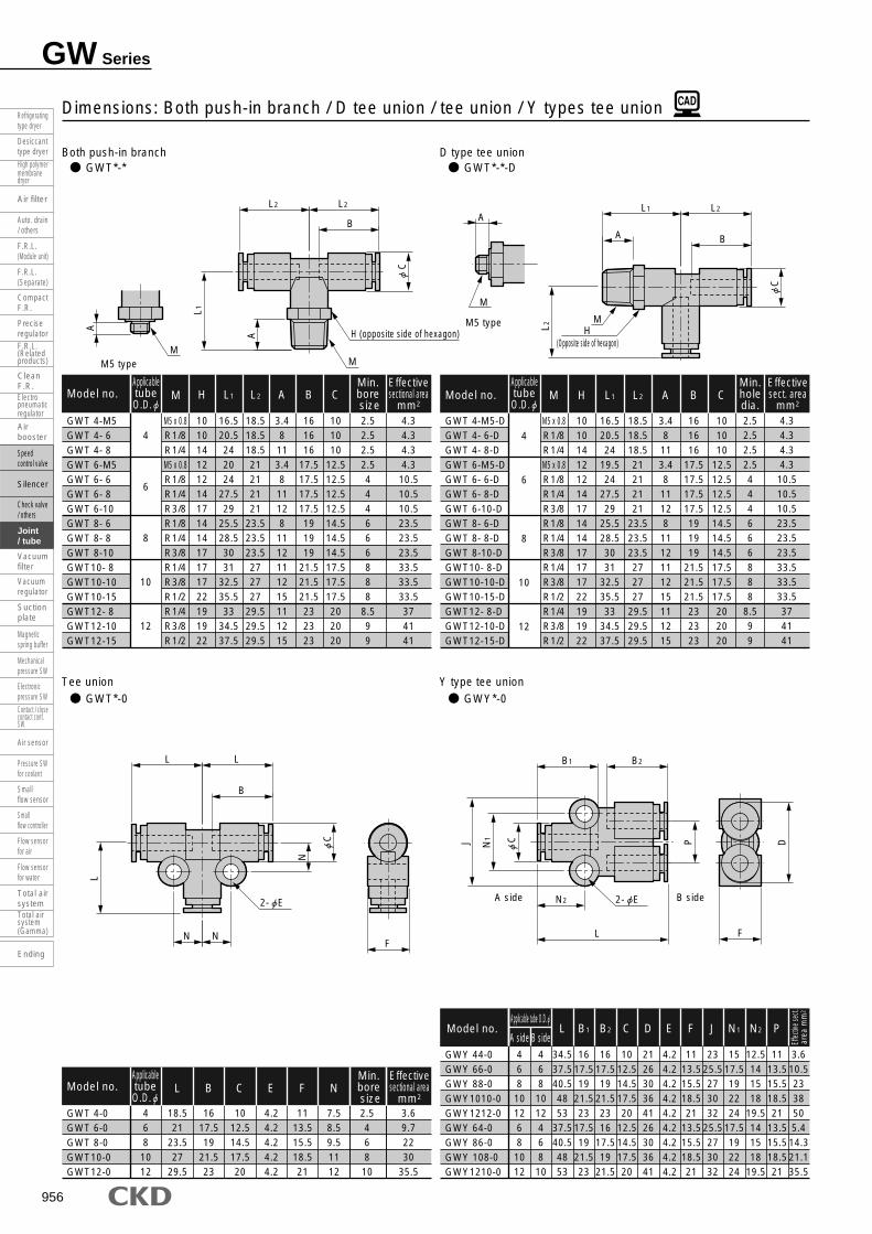
GWY 44-0GWY 66-0GWY 88-0GWY1010-0GWY1212-0GWY 64-0GWY 86-0GWY 108-0GWY1210-0
A side4681012681012
L
34.537.540.54853
37.540.54853
B side468101246810
B1
1617.519
21.523
17.519
21.523
B2
1617.519
21.52316
17.519
21.5
C
1012.514.517.520
12.514.517.520
D
212630364126303641
E
4.24.24.24.24.24.24.24.24.2
F
1113.515.518.521
13.515.518.521
J
2325.5273032
25.5273032
N1
1517.5192224
17.5192224
N2
12.5141518
19.5141518
19.5
P
1113.515.518.521
13.515.518.521
Effec
tive s
ect.
area
mm
2
3.610.52338505.4
14.321.135.5
Model no.
Both push-in branch D type tee unionGWT*-* GWT*-*-D
Dimensions: Both push-in branch / D tee union / tee union / Y types tee union
GWT 4-M5GWT 4- 6GWT 4- 8GWT 6-M5GWT 6- 6GWT 6- 8GWT 6-10GWT 8- 6GWT 8- 8GWT 8-10GWT10- 8GWT10-10GWT10-15GWT12- 8GWT12-10GWT12-15
Model no.ApplicabletubeO.D.
ApplicabletubeO.D.
4
6
8
10
12
M
M5 x 0.8R1/8R1/4M5 x 0.8R1/8R1/4R3/8R1/8R1/4R3/8R1/4R3/8R1/2R1/4R3/8R1/2
H
10101412121417141417171722191922
L2
18.518.518.521212121
23.523.523.5272727
29.529.529.5
L1
16.520.5242024
27.529
25.528.53031
32.535.533
34.537.5
A
3.48113.48111281112111215111215
B
161616
17.517.517.517.5191919
21.521.521.5232323
C
101010
12.512.512.512.514.514.514.517.517.517.5202020
Min.bore size2.52.52.52.5444666888
8.599
Effectivesectional area
mm2
Effectivesect. area
mm2
4.34.34.34.310.510.510.523.523.523.533.533.533.5374141
GWT 4-0GWT 6-0GWT 8-0GWT10-0GWT12-0
Model no.
4681012
E
4.24.24.24.24.2
N
7.58.59.51112
C
1012.514.517.520
B
1617.519
21.523
L
18.521
23.527
29.5
F
1113.515.518.521
2.546810
3.69.72230
35.5
GWT 4-M5-DGWT 4- 6-DGWT 4- 8-DGWT 6-M5-DGWT 6- 6-DGWT 6- 8-DGWT 6-10-DGWT 8- 6-DGWT 8- 8-DGWT 8-10-DGWT10- 8-DGWT10-10-DGWT10-15-DGWT12- 8-DGWT12-10-DGWT12-15-D
Model no. M
M5 x 0.8R1/8R1/4M5 x 0.8R1/8R1/4R3/8R1/8R1/4R3/8R1/4R3/8R1/2R1/4R3/8R1/2
H
10101412121417141417171722191922
L1
16.520.524
19.524
27.529
25.528.53031
32.535.533
34.537.5
L2
18.518.518.521212121
23.523.523.5272727
29.529.529.5
A
3.48113.48111281112111215111215
B
161616
17.517.517.517.5191919
21.521.521.5232323
C
101010
12.512.512.512.514.514.514.517.517.517.5202020
Min.holedia.2.52.52.52.5444666888
8.599
4.34.34.34.3
10.510.510.523.523.523.533.533.533.5374141
4
6
8
10
12
Applicable tube O.D.
ApplicabletubeO.D.
Min.bore size
Effectivesectional area
mm2
Tee union Y type tee unionGWT*-0 GWY*-0
B
H (opposite side of hexagon)
MM
N N F
N2
L
B2B1
DP
CN1J
L2L2
B
L2L1
F
C
C
A
A
L1
L2
M
MH
(Opposite side of hexagon)
A
A
C
N
2- E 2- E
L
B
LL
A side B side
Refrigerating type dryer
Desiccant type dryer
High polymer membrane dryer
Auto. drain/ others
F.R.L.(Module unit)
F.R.L.(Separate)
F.R.L.(Related products)
CleanF.R.
Airbooster
Speed control valve
Check valve/ others
Joint/ tube
Suction plate
Magnetic spring buffer
Mechanical pressure SW
Electronic pressure SW
Contact / close contact conf.SW
Small flow controller
Small flow sensor
Flow sensorfor air
Flow sensor for water
Total air systemTotal air system(Gamma)
Air filter
Precise regulator
Electro pneumatic regulator
Silencer
Vacuum regulator
Air sensor
Pressure SWfor coolant
Ending
Compact F.R.
Vacuum filter

957
Join
tJo
int/t
ube
Refrigerating type dryer
Desiccant type dryer
High polymer membrane dryer
Auto. drain/ others
F.R.L.(Module unit)
F.R.L.(Separate)
F.R.L.(Related products)
CleanF.R.
Airbooster
Speed control valve
Check valve/ others
Joint/ tube
Suction plate
Magnetic spring buffer
Mechanical pressure SW
Electronic pressure SW
Contact / close contact conf.SW
Small flow controller
Small flow sensor
Flow sensorfor air
Flow sensor for water
Total air systemTotal air system(Gamma)
Air filter
Precise regulator
Electro pneumatic regulator
Silencer
Vacuum regulator
Air sensor
Pressure SWfor coolant
Ending
Compact F.R.
Vacuum filter
GWCR 8-0GWCR10-0GWCR12-0
81012
L
2427.530
C
14.517.520
B
1921.523
E
4.24.24.2
F
15.518.521
N
9.51112
Min.boresize
68
10
Effectivesectional area
mm2
2230.535.9
Model no.
Both ports Y tee union Cross shapedGWY*-* GWCR*-0
Dimensions: Both ports Y tee union / cross shaped / 2 port turn elbow / tetrapod shaped (with R)
GWY 4-M5GWY 4- 6GWY 4- 8GWY 6-M5GWY 6- 6GWY 6- 8GWY 6-10GWY 8- 6GWY 8- 8GWY 8-10GWY10- 8GWY10-10GWY10-15GWY12- 8GWY12-10GWY12-15
Model no.ApplicabletubeO.D.
ApplicabletubeO.D.
ApplicabletubeO.D.
4
6
8
10
12
4
6
8
10
12
M
M5 x 0.8R1/8R1/4M5 x 0.8R1/8R1/4R3/8R1/8R1/4R3/8R1/4R3/8R1/2R1/4R3/8R1/2
L
3842
45.5414649
50.54952
53.559.56164
64.56669
H
12121414141417171717191922222222
A
3.48113.48111281112111215111215
B
161616
17.517.517.517.5191919
21.521.521.5232323
D
21212126262626303030363636414141
E
4.24.24.24.24.24.24.24.24.24.24.24.24.24.24.24.2
F
111111
13.513.513.513.515.515.515.518.518.518.5212121
J
232323
25.525.525.525.5272727303030323232
P
111111
13.513.513.513.515.515.515.518.518.518.5212121
Effec
tive s
ect.
area
mm
24.55.55.54.5
17.517.517.525.525.525.535
38.5383737
40.5
GWL 4-M5-2TGWL 6- 6-2TGWL 8- 8-2TGWL10-10-2TGWL12-15-2T
Model no.
4681012
M
M5 x 0.8R1/8R1/4R3/8R1/2
L1
21.52428
31.535.5
H
88121417
L2
18.52632
36.542.5
A
3.48111215
B
1617.519
21.523
C
1012.514.517.520
D
33444
O
2126303641
P
1113.515.518.521
Effec
tive s
ect.
area
mm
2
3.68.5192634
GWTR 4-M5GWTR 4- 6GWTR 4- 8GWTR 6-M5GWTR 6- 6GWTR 6- 8GWTR 6-10GWTR 8- 6GWTR 8- 8GWTR 8-10GWTR10- 8GWTR10-10GWTR10-15GWTR12- 8GWTR12-10GWTR12-15
Model no. M
M5 x 0.8
R1/8
R1/4
M5 x 0.8
R1/8
R1/4
R3/8
R1/8
R1/4
R3/8
R1/4
R3/8
R1/2
R1/4
R3/8
R1/2
H
10101414141417171717191922222222
L1
22.526.530253033
34.532.535.537
39.54144
41.54346
L2
191919
21.521.521.521.5242424
27.527.527.5303030
A
3.48
113.48
11128
1112111215111215
B
161616
17.517.517.517.5191919
21.521.521.5232323
C
101010
12.512.512.512.514.514.514.517.517.517.5202020
E
4.24.24.24.24.24.24.24.24.24.24.24.24.24.24.24.2
F
111111
13.513.513.513.515.515.515.518.518.518.5212121
N
7.57.57.58.58.58.58.59.59.59.5131313141414
Min.holedia.2.52.52.52.5444666888
8.58.58.5
Effec
tive s
ect.
area
mm
2
4.34.54.54.310.510.510.523.523.523.535.535.535.537.537.537.5
ApplicabletubeO.D.
2 port turn elbow Tetrapod shaped (with R)GWL*-*-2T GWTR*-*
B
A
A
M
M
H (opposite side of hexagon) 2- E
2- E
L1
O
P
F
L1L2
C
N
L2 B
N
F
L
L L
F
L
B
L
N N
B
E
DPJ
C
C
L2 C
DA
M
M
H (opposite side of hexagon)
A
M5 type
M5 type
MM
H (opposite side of hexagon)
A A
M5 type
GW Series
Dimensions

958
GW Series
GWTR 4-0GWTR 6-0GWTR 8-0GWTR10-0GWTR12-0
4681012
L
1921.524
27.530
C
1012.514.517.520
B
1617.519
21.523
E
4.24.24.24.24.2
F
1113.515.518.521
N
7.58.59.51314
Min.boresize2.546810
Effectivesectional area
mm2
49.512.529.535.5
Model no.
FY type (with R) Double Y type (with R)GWFY*-* GWWY*-*
Dimensions: FY type (with R) / double Y type (with R) / terapod shaped / FY type
4681012
GWFY 4-0GWFY 6-0GWFY 8-0GWFY10-0GWFY12-0
Model no. L1
17.519.522
25.528
L2
23.5272933
35.5
B
1617.519
21.523
C
1012.514.517.520
D
2126303641
E
3.24.24.24.24.2
F
1113.515.518.521
G
1822.526.531.537
N
15.5171820
21.5
P
1113.515.518.521
Min.holedia.2.5468
10
4102129
35.5
4
6
GWWY4-M5GWWY4- 6GWWY4- 8GWWY6-M5GWWY6- 6GWWY6- 8GWWY6-10
Model no. M
M5 x 0.8
R1/8
R1/4
M5 x 0.8
R1/8
R1/4
R3/8
H
14141417171717
L
42.547.550.546.551.554.556
A
3.48113.481112
B
161616
17.517.517.517.5
C
101010
12.512.512.512.5
D
21212126262626
E
3.23.23.23.23.23.23.2
F
22222227272727
N
15.515.515.517171717
P
111111
13.513.513.513.5
4.39.79.74.3232323
ApplicabletubeO.D.
ApplicabletubeO.D.
4
6
8
10
12
GWFY 4-M5GWFY 4- 6GWFY 4- 8GWFY 6-M5GWFY 6- 6GWFY 6- 8GWFY 6-10GWFY 8- 6GWFY 8- 8GWFY 8-10GWFY10- 8GWFY10-10GWFY10-15GWFY12- 8GWFY12-10GWFY12-15
Model no. M
M5 x 0.8
R1/8
R1/4
M5 x 0.8
R1/8
R1/4
R3/8
R1/8
R1/4
R3/8
R1/4
R3/8
R1/2
R1/4
R3/8
R1/2
H
10101414141417171717191922222222
L1
212528.523283132.530.533.53537.5394239.54144
L2
23.523.523.527272727292929333333
35.535.535.5
A
3.48113.48111281112111215111215
B
161616
17.517.517.517.5191919
21.521.521.5232323
C
10101012.512.512.512.514.514.514.517.517.517.5202020
D
21212126262626303030363636414141
E
3.23.23.24.24.24.24.24.24.24.24.24.24.24.24.24.2
G
18181822.522.522.522.526.526.526.531.531.532.5373737
N
15.515.515.51717171718181820202021.521.521.5
P
11111113.513.513.513.515.515.515.518.518.518.5212121
F
11111113.513.513.513.515.515.515.518.518.518.5212121
Min.holedia.2.52.52.52.5444666888
8.58.58.5
Effec
tive s
ect.
area
mm
2
Effec
tive s
ect.
area
mm
2
4.54.64.64.510.510.510.5232323
34.434.434.437.537.537.5
ApplicabletubeO.D.
ApplicabletubeO.D. Ef
fectiv
e sec
t.ar
ea m
m2
Tetrapod shaped FY typeGWTR*-0 GWFY*-0
FD
P
C
M
EM
M
M
H (opposite side of hexagon)
H (opposite side of hexagon) E
F
C
L
B
D
L1
P
G
C N
L2
B
F
AA
L1G
LF
A B
N
B
L2
N
C
D
C
P
PN
A
L
E
N
M5 type
M5 type
E
B
Refrigerating type dryer
Desiccant type dryer
High polymer membrane dryer
Auto. drain/ others
F.R.L.(Module unit)
F.R.L.(Separate)
F.R.L.(Related products)
CleanF.R.
Airbooster
Speed control valve
Check valve/ others
Joint/ tube
Suction plate
Magnetic spring buffer
Mechanical pressure SW
Electronic pressure SW
Contact / close contact conf.SW
Small flow controller
Small flow sensor
Flow sensorfor air
Flow sensor for water
Total air systemTotal air system(Gamma)
Air filter
Precise regulator
Electro pneumatic regulator
Silencer
Vacuum regulator
Air sensor
Pressure SWfor coolant
Ending
Compact F.R.
Vacuum filter

959
Join
tJo
int/t
ube
Refrigerating type dryer
Desiccant type dryer
High polymer membrane dryer
Auto. drain/ others
F.R.L.(Module unit)
F.R.L.(Separate)
F.R.L.(Related products)
CleanF.R.
Airbooster
Speed control valve
Check valve/ others
Joint/ tube
Suction plate
Magnetic spring buffer
Mechanical pressure SW
Electronic pressure SW
Contact / close contact conf.SW
Small flow controller
Small flow sensor
Flow sensorfor air
Flow sensor for water
Total air systemTotal air system(Gamma)
Air filter
Precise regulator
Electro pneumatic regulator
Silencer
Vacuum regulator
Air sensor
Pressure SWfor coolant
Ending
Compact F.R.
Vacuum filter
GW Series
Dimensions
Double Y type Blanking plug
L type plug C type plug
GWWY*-0 GWP*-B
GWP*-L GWP*-C
Dimensions: Double Y / blanking plug / L plug / C types plug
GWWY64-0GWWY86-0
Model no.B side
46
A side
Applicable tube O.D.
68
L
3943
B1
17.519
B2
1617.5
C1
12.514.5
C2
1012.5
D
2126
E
3.23.2
F
2227
N
15.517
P
1113.5
Effec
tive s
ect.
area
mm
2
922
GWP 44-LGWP 46-LGWP 48-LGWP 66-LGWP 68-LGWP 610-LGWP 88-LGWP 810-LGWP 812-LGWP1010-LGWP1012-LGWP1212-L
Model no.ApplicabletubeO.D.
ApplicabletubeO.D.
4
6
8
10
12
A
1413.513.516.516.516.517.517.51720
19.521.5
L2
18.518.518.5212121
23.523.523.52727
29.5
L1
3031
32.534
35.538
36.53940
41.542.544.5
Jointportsize
Jointportsize
468681081012101212
B
161616
17.517.517.5191919
21.521.523
C
101010
12.512.512.514.514.514.517.517.520
Min.boresize1.71.71.73.43.43.45.45.45.46.86.88.8
Effectivesectional area
mm2
Min.boresize
Effectivesectional area
mm2
2.12.12.16.76.76.716.616.616.624.724.734
GWP 44-CGWP 46-CGWP 48-CGWP 66-CGWP 68-CGWP 610-CGWP 88-CGWP 810-CGWP 812-CGWP1010-CGWP1012-CGWP1212-C
Model no.
4
6
8
10
12
A
1413.513.516.516.516.517.517.51720
19.521.5
L2
18.518.518.5212121
23.523.523.52727
29.5
L1
3031
32.534
35.538
36.53940
41.542.544.5
468681081012101212
B
161616
17.517.517.5191919
21.521.523
C
101010
12.512.512.514.514.514.517.517.520
1.71.71.73.43.43.45.45.45.46.86.88.8
2.42.42.47.37.37.3
19.319.319.328.628.635.5
GWJP 3-BGWP 4-BGWP 6-BGWP 8-BGWP10-BGWP12-BGWP16-B
Model no. L
23.5272933404351
1111
11.514
18.52023
d
568
10121421
Joint port size
3.2468101216
E
L2
B
L1
A
B
L2L2
L
Connecting joint
C
A
C
L1
N
Applicable tube
Connecting joint
Applicable tube
Connecting joint
P d
D
C
2
C
1
C
2
P
FB2B1
L
B sideA side
* For connecting joint, dimension of CKD (GW Series) are shown.
Material: Polyamide resin
**
* For connecting joint, dimension of CKD (GW Series) are shown.* For connecting joint, dimension of CKD (GW Series) are shown.
*

960
GW Series
GWMF 46-0GWMF 48-0GWMF 68-0GWMF610-0GWMF810-0
Model no.Q2
688
1010
Q1
*
44668
L1
646673
78.584.5
L2
18.519.52122
23.5
B1
1616
17.517.519
B2
18.519.52122
23.5
C
12.514.514.517.517.5
F
13.515.515.518.518.5
N1
10.511.511.51313
N2
3939
46.546.552.5
P
10.510.5131315
Effec
tive s
ect.
area
mm
2
7.922223030
Y type plug CapGWP*-Y GWC*
Dimensions: Y type plug / cap / manifold (single with R) / manifold (single)
GWMF 46- 6GWMF 48- 8GWMF 68- 8GWMF610-10GWMF810-10
Model no.Q2
6881010
Q1
*
44668
M
R1/8R1/4R1/4R3/8R3/8
H
1417171919
L1
72.577.584.591.597.5
L2
18.519.52122
23.5
A
811111212
B1
161617.517.519
B2
17.51919
21.521.5
C
12.514.514.517.517.5
F
13.515.515.518.518.5
N1
10.511.511.51313
N2
393946.546.552.5
P
10.510.5131315
Effec
tive s
ect.
area
mm
2
8.324.224.235.535.5
GWP 44-YGWP 46-YGWP 48-YGWP 66-YGWP 68-YGWP 610-YGWP 88-YGWP 810-YGWP 812-YGWP1010-YGWP1012-YGWP1212-Y
Model no.ApplicabletubeO.D.
4
6
8
10
12
B
161616
17.517.517.5191919
21.521.523
A
35.535353838384141
40.548.54853
L
51.552.554
55.557
59.560
62.563.5707176
Jointportsize
468681081012101212
D
212121262626303030363641
E
4.24.24.24.24.24.24.24.24.24.24.24.2
F
111111
13.513.513.515.515.515.518.518.521
J
232323
25.525.525.5272727303032
P
111111
13.513.513.515.515.515.518.518.521
Min.boresize1.72.52.53.944
5.966
6.88
8.8
Effectivesectional area
mm2
2.15.85.89.1
15.915.922.224.924.928.235.536.3
GWC 4GWC 6GWC 8GWC10GWC12
Model no. B
1617.519
21.523
C
1012.514.517.520
L
1819.5212426
Applicabletube O.D.
468
1012
Manifold (single with R) Manifold (single solenoid)GWMF*-* GWMF*-0
2- E
N2
F
L1
PA
B2
L
B
N1
B1
C
L2
B
2- 4.5
3-Q1 applicable tube outer diameter
Q2 applicable tube outer diameter
N2
F
L1
P
B2
N1
B1
C
L2
2- 4.5
3-Q1 applicable tube outer diameter
2-Q2 applicable tube outer diameter
HM
P D CJ
FA
L
Applicable tube
Connecting joint
* For connecting joint, dimension of CKD (GW Series) are shown.
*
* Applicable tube O.D.
Refrigerating type dryer
Desiccant type dryer
High polymer membrane dryer
Auto. drain/ others
F.R.L.(Module unit)
F.R.L.(Separate)
F.R.L.(Related products)
CleanF.R.
Airbooster
Speed control valve
Check valve/ others
Joint/ tube
Suction plate
Magnetic spring buffer
Mechanical pressure SW
Electronic pressure SW
Contact / close contact conf.SW
Small flow controller
Small flow sensor
Flow sensorfor air
Flow sensor for water
Total air systemTotal air system(Gamma)
Air filter
Precise regulator
Electro pneumatic regulator
Silencer
Vacuum regulator
Air sensor
Pressure SWfor coolant
Ending
Compact F.R.
Vacuum filter

961
Join
tJo
int/t
ube
Refrigerating type dryer
Desiccant type dryer
High polymer membrane dryer
Auto. drain/ others
F.R.L.(Module unit)
F.R.L.(Separate)
F.R.L.(Related products)
CleanF.R.
Airbooster
Speed control valve
Check valve/ others
Joint/ tube
Suction plate
Magnetic spring buffer
Mechanical pressure SW
Electronic pressure SW
Contact / close contact conf.SW
Small flow controller
Small flow sensor
Flow sensorfor air
Flow sensor for water
Total air systemTotal air system(Gamma)
Air filter
Precise regulator
Electro pneumatic regulator
Silencer
Vacuum regulator
Air sensor
Pressure SWfor coolant
Ending
Compact F.R.
Vacuum filter
GW Series
Dimensions
GWMF4 8-0-WGWMF610-0-WGWMF812-0-W
Model no.Q2
81012
Q1
468
L1
6678.587
L2
19.522
24.5
L3
29.53236
B1
1617.519
B2
1921.523
F1
1010
11.5
F2
17.519.522
N1
10.51213
N2
384551
P
10.51315
Effec
tive s
ect.
area
mm
2
2230.436
Manifold (double with R) Manifold (double solenoid)GWMF*-*-W GWMF*-0-W
Dimensions: Manifold (double with R) / manifold (double) / insert ring
GWMF 48- 8-WGWMF 48-10-WGWMF610-10-WGWMF610-15-WGWMF812-10-WGWMF812-15-W
Model no.Q2
8810101212
Q1
Applicabletube O.D.
446688
M
R1/4R3/8R3/8R1/2R3/8R1/2
H
171719192222
L1
77.57991.594.5100103
L2
19.519.5222224.524.5
L3
29.529.532323636
A
111212151215
B1
161617.517.51919
B2
191921.521.52323
F1
1010101011.511.5
F2
17.517.519.519.52222
N1
10.510.512121313
N2
383845455151
P
10.510.513131515
Effe
ctive
sect.
area
mm
2
24.323.535.835.838.238.2
Applicabletube O.D.
N2
F2
L3
F1
L1
PA
B2 L2
N1
B1 L2
2- 4.5
6-Q1 applicable tube outer diameter
Q2 applicable tube outer diameter
HM
N2
F2
L3
F1
L1
P
B2 L2
N1
B1 L2
2- 4.5
6-Q1 applicable tube outer diameter
2-Q2 applicable tube outer diameter
Insert ring (tube ) (custom order)
INS-U*-1
B
C
A
L
Model no. A B C LINS-U32-1INS-U04-1INS-U06-1INS-U08-1INS-U10-1INS-U12-1
1.11.134
5.57
2.23579
11
1.71.83.84.86.37.8
12.7171821
23.525
Tube
* Tube NU is a custom order.* Use insert ring if tube U-92*, U-95* or NU is used for a vacuum circuit.
Material: Brass + electroless nickeling
U-92*U-95*
U-92*U-95*

962
GWJ Joint (mini-type)Port size M3 to 1/8 (Rc or R)
Small push-in joint with wide variation
Space saving type with smaller body. Dead space of pipe can be decreased dramatically.
StraightGWJS3-0
Bulk headGWJS3-0-X
Female straightGWJS3-*-M
Single straightGWJS*-*
ElbowGWJL3-0
Long elbowGWJL*-*-L
Single elbowGWJL*-*
Different diameter straightGWJS*-0
Y type tee unionGWJY*-0
Tee unionGWJT3-0
D type tee unionGWJT3-*-D
Both push-in branchGWJT3-*
Blanking plugGWJP3-B
Sales unit is 10 pieces/1 box.
Straight type
Tee union type
Plug
Elbow type
Applicable tubeO.D.
Applicable tubeO.D.
Applicable tubeO.D.
Applicable tubeO.D.
Applicable tubeO.D.
Applicable tubeO.D.
Applicable tubeO.D.
Applicable tubeO.D.
Applicable tubeO.D.
Applicable tubeO.D.
Applicable tubeO.D.
Applicable tubeO.D.
Applicable tubeO.D.
3.2
4
6
3.2 3.2 3.2
3.2, 4
3.2, 6
3.2
4
6
3.2
4
6
3.2
3.2
3.2
3.2 3.2 3.2, 3.2
3.2, 4
· Page: 964 · Page: 964 · Page: 964 · Page: 964
· Page: 964 · Page: 964 · Page: 965 · Page: 965
· Page: 965 · Page: 965 · Page: 965 · Page: 965
· Page: 966
962
Refrigerating type dryer
Desiccant type dryer
High polymer membrane dryer
Auto. drain/ others
F.R.L.(Module unit)
F.R.L.(Separate)
F.R.L.(Related products)
CleanF.R.
Airbooster
Speed control valve
Check valve/ others
Joint/ tube
Suction plate
Magnetic spring buffer
Mechanical pressure SW
Electronic pressure SW
Contact / close contact conf.SW
Small flow controller
Small flow sensor
Flow sensorfor air
Flow sensor for water
Total air systemTotal air system(Gamma)
Air filter
Precise regulator
Electro pneumatic regulator
Silencer
Vacuum regulator
Air sensor
Pressure SWfor coolant
Ending
Compact F.R.
Vacuum filter

963
Join
t / m
ini-t
ype
Join
t/tub
e
Refrigerating type dryer
Desiccant type dryer
High polymer membrane dryer
Auto. drain/ others
F.R.L.(Module unit)
F.R.L.(Separate)
F.R.L.(Related products)
CleanF.R.
Airbooster
Speed control valve
Check valve/ others
Joint/ tube
Suction plate
Magnetic spring buffer
Mechanical pressure SW
Electronic pressure SW
Contact / close contact conf.SW
Small flow controller
Small flow sensor
Flow sensorfor air
Flow sensor for water
Total air systemTotal air system(Gamma)
Air filter
Precise regulator
Electro pneumatic regulator
Silencer
Vacuum regulator
Air sensor
Pressure SWfor coolant
Ending
Compact F.R.
Vacuum filter
DCBA
DescriptionsWorking fluid
Max. working pressure MPa
Working temperature
Applicable tube
Compressed air
1.0
-10 to 60 (no freezing)
Soft nylon tube (model no. F-1532, F-1504, F-1506)
Urethane tube (model no. U-9532, U-9504, U-9506, NU-04, NU-06) Note
GWJ
Specifications
A ShapeS
L
Y
T
P
Straight
Elbow
Y type tee union
Tee union
Plug
3
4
6
3.2
4
6
M3
M5
6
0
4P
6P
B
M3 x 0.5
M5 x 0.8
R1/8
No thread
Plug for 4
Plug for 6
Blanking plug
L
D
X
M
Long
D type
Bulk head
Female type
GWJ S 3 6 M
How to order
Internal structure and main parts list
B Applicable tube O.D. C Port size D Other combinations
No. Name Material
1 Body *1Brass (electroless nickeling treatment)
PBT
2 Packing seal Nitrile rubber
3 Holder Brass (electroless nickeling treatment)
4 Chuck Stainless steel
5 Outer ringMetal type polyacetal
Resin type brass (electroless nickeling treatment)
6 Push ring Polyacetal
* Refer to model no. selections in dimensions (pages 964 to 966) for combination of model no.
Note: Refer to page 1012 for tube dimensions, ambient temperature and working pressure.
Note: Sales unit is 10 pieces/1 box.
*1: The body of the single-ended straight, female straight, and bulkhead is brass (electroless nickel plated).
1 2 3
4
5 6
GWJ Series
Specifications
Clean room specifications (catalog No. CB-033SA)
GWJ
GWJ
- ·················· -
- ·················· -
P7*
P80

964
GWJ Series
GWJS3-0-X
Model no.
3.2
HEX
12
B
12.5
L
26.5
M
M10 x 1.0
Min.hole
diameter2.5
Panelthickness/ G5
Panelhole
diameter10.5 2.5 GWJS3-0
Model no. Applicable tubeO.D.
3.2
C
8.5
B
12.5
L
27.5
Min.hole
diameter
Min.hole
diameter
2.2
Effectivesect. area
mm2
2.5
GWJS34-0GWJS36-0
Model no.A side
Applicable tube O.D.
46
B side3.23.2
B1
13.514.5
L
28.528.5
B2
12.512.5
C1
9.611.8
C2
8.58.8
Min.holediameter2.22.2
Effectivesect. areamm2
2.52.5
GWJS3-M3-MGWJS3-M5-MGWJS3-6-M
Model no.
3.2
RcM
M3 x 0.5M5 x 0.8
1/8
L
17.518.521.5
HEX
8812
A
458
B
12.512.512.5
C
7.87.88.5
7.08.011.0
2.52.52.5
2.52.52.5
Single straight Female straight
GWJS*-* GWJS3-*-M
Dimensions: Single straight / female straight / bulk head / straight / different diameter straight / single elbow
* dimension is for model with punched hexagon hole.
GWJS3-M3GWJS3-M5GWJS3- 6GWJS4-M3GWJS4-M5GWJS4- 6GWJS6-M5GWJS6- 6
Model no.ApplicabletubeO.D.
ApplicabletubeO.D.
ApplicabletubeO.D.
3.2
4
6
RM
M3 x 0.5M5 x 0.8
1/8M3 x 0.5M5 x 0.8
1/8M5 x 0.8
1/8
K
8.88.811111111
12.112.1
HEX
88101010101111
L
1718
16.518192020
21.5
A
2.43.48
2.43.48
3.48
B
12.512.512.513.513.513.514.514.5
Min.hole
diameter
Min.holediameter
1.22.52.51.22.52.52.54
*
*
*
Effectivesect. areamm2
Effectivesect. areamm2
Effectivesect. areamm2
Effectivesect. areamm2
0.92.52.50.944411
GWJL3-M3GWJL3-M5GWJL3- 6GWJL4-M3GWJL4-M5GWJL4- 6GWJL6-M5GWJL6- 6
Model no.
3.2
4
6
RM
M3 x 0.5M5 x 0.81/8
M3 x 0.5M5 x 0.81/8
M5 x 0.81/8
L1
1313
17.51313
17.515.518.5
HEX
881088101010
L2
15.515.515.516.516.516.518.518.5
A
2.43.48
2.43.48
3.48
B
12.512.512.513.513.513.514.514.5
C
8.58.58.59.69.69.611.811.8
1.22.22.21.22.52.52.54
0.82.52.30.833
3.59.5
ApplicabletubeO.D.
Bulk head Straight
GWJS3-0-X GWJS3-0
Different diameter straight Single elbow
GWJS*-0 GWJL*-*
K
B
A B
L
C
B
L
C
2
C
C
1
B2B1
L
A
L
A
HEX (opposite side of hexagon)
B B
L
G
(max.)HEX (opposite side of hexagon)
HEX (opposite side of hexagon)
R M
M
R
HEX(Opposite side of hexagon)
RcM
C
L2
B
A
L1
A
B sideA side
M
Refrigerating type dryer
Desiccant type dryer
High polymer membrane dryer
Auto. drain/ others
F.R.L.(Module unit)
F.R.L.(Separate)
F.R.L.(Related products)
CleanF.R.
Airbooster
Speed control valve
Check valve/ others
Joint/ tube
Suction plate
Magnetic spring buffer
Mechanical pressure SW
Electronic pressure SW
Contact / close contact conf.SW
Small flow controller
Small flow sensor
Flow sensorfor air
Flow sensor for water
Total air systemTotal air system(Gamma)
Air filter
Precise regulator
Electro pneumatic regulator
Silencer
Vacuum regulator
Air sensor
Pressure SWfor coolant
Ending
Compact F.R.
Vacuum filter

965
Join
t / m
ini-t
ype
Join
t/tub
e
Refrigerating type dryer
Desiccant type dryer
High polymer membrane dryer
Auto. drain/ others
F.R.L.(Module unit)
F.R.L.(Separate)
F.R.L.(Related products)
CleanF.R.
Airbooster
Speed control valve
Check valve/ others
Joint/ tube
Suction plate
Magnetic spring buffer
Mechanical pressure SW
Electronic pressure SW
Contact / close contact conf.SW
Small flow controller
Small flow sensor
Flow sensorfor air
Flow sensor for water
Total air systemTotal air system(Gamma)
Air filter
Precise regulator
Electro pneumatic regulator
Silencer
Vacuum regulator
Air sensor
Pressure SWfor coolant
Ending
Compact F.R.
Vacuum filter
GWJL3-0
Model no.
3.2
L
15.5
B
12.5
C
8.5
D
5.7
E
3.2
Min.holediameter2.2
Effectivesect. areamm2
Min.holediameter
Effectivesect. areamm2
Effectivesect. areamm2
2.3
GWJT3-0
Model no.
3.2
L
15.5
B
12.5
C
8.5
D
5.7
E
3.2 2.72.2
GWJL3-M3-LGWJL3-M5-LGWJL3- 6-LGWJL4-M5-LGWJL4- 6-LGWJL6-M5-LGWJL6- 6-L
Model no.ApplicabletubeO.D.
ApplicabletubeO.D.
3.2
4
6
RM
M3 x 0.5M5 x 0.8
1/8M5 x 0.8
1/8M5 x 0.8
1/8
L1
25.525.530
25.530
30.533.5
HEX
88108101010
L2
15.515.515.516.516.518.518.5
A
2.43.48
3.48
3.48
B
12.512.512.513.513.514.514.5
C
8.58.58.59.69.611.811.8
Effectivesect. areamm2
0.82.32.333
3.58.5
Min.hole
diameter
Effectivesect. areamm2
Min.hole
diameter
ApplicabletubeO.D.
Effectivesect. areamm2
Min.hole
diameter
1.22.22.22.52.52.54
GWJT3-M3GWJT3-M5GWJT3-6
Model no.
3.2
RM
M3 x 0.5M5 x 0.81/8
L1
1313
17.5
HEX
8810
L2
15.515.515.5
A
2.43.48
B
12.512.512.5
C
8.58.58.5
1.22.22.2
0.92.72.7
GWJT3-M3-DGWJT3-M5-DGWJT3-6-D
Model no.
3.2
RM
M3 x 0.5M5 x 0.81/8
L1
1313
17.5
HEX
8810
L2
15.515.515.5
A
2.43.48
B
12.512.512.5
C
8.58.58.5
1.22.22.2
0.92.72.7
GWJY33-0GWJY43-0
Model no.A side
Applicable tube O.D.
3.24
B side3.23.2
B1
12.513.5
L
2728.5
B2
12.512.5
C
8.59.6
D1
11.212.2
D2
10.512
E
3.23.2
F
1717
P
8.58.5
G
17.718.7
2.72.7
Long elbow ElbowGWJL*-*-L GWJL3-0
Dimensions: Long elbow / elbow / both push-in branch / D tee union / tee union / Y type tee union
ApplicabletubeO.D.
ApplicabletubeO.D.
Both push-in branch D type tee unionGWJT3-* GWJT3-*-D
Tee union Y type tee unionGWJT3-0 GWJY*-0
L
B
C
C
C
C
L
D
D
L2 L2
B
L1
A
HEX (opposite side of hexagon)
R
HEX (opposite side of hexagon)
R
M
M
E
L2
B
A
A
L2
L1L2
AD
1G C
B
HEX (opposite side of hexagon)
RM
A
L1
A
LL B2B1
L
D2
B
C
L
D
FP
DD
2- E 2- E B sideA side
GWJ Series
Dimensions

966
GWJ Series
GWJP3-BGWP 4-BGWP 6-B
Model no. Joint portsize
3.246
D
568
1111
11.5
L
23.52729
Blanking plugGWJP3-BGWP*-B
Dimensions: Blanking plug
Material: Polyamide
*
* Dimension of CKD connecting joints (GW and GWJ series) are shown.
D
L
Connecting joint
Refrigerating type dryer
Desiccant type dryer
High polymer membrane dryer
Auto. drain/ others
F.R.L.(Module unit)
F.R.L.(Separate)
F.R.L.(Related products)
CleanF.R.
Airbooster
Speed control valve
Check valve/ others
Joint/ tube
Suction plate
Magnetic spring buffer
Mechanical pressure SW
Electronic pressure SW
Contact / close contact conf.SW
Small flow controller
Small flow sensor
Flow sensorfor air
Flow sensor for water
Total air systemTotal air system(Gamma)
Air filter
Precise regulator
Electro pneumatic regulator
Silencer
Vacuum regulator
Air sensor
Pressure SWfor coolant
Ending
Compact F.R.
Vacuum filter

968C 968
ZW Joint Stainless steel seriesPort size M5 to R1/2
Single straightZW-S*-*
Applicable tubeO.D.
Applicable tubeO.D.
Applicable tubeO.D.
Applicable tubeO.D.
Applicable tubeO.D.
4
6
8
10
12
· Page: 971
ElbowZW-L*-0
4
6
8
10
12
· Page: 971
StraightZW-S*-0
· Sales unit is 1 piece per bag.
4
6
8
10
12
· Page: 971
Single elbowZW-L*-*
4
6
8
10
12
· Page: 971
Tee unionZW-T*-0
4
6
8
10
12
· Page: 971
968
Refrigerating type dryer
Desiccant type dryer
High polymer membrane dryer
Auto. drain/ others
F.R.L.(Module unit)
F.R.L.(Separate)
F.R.L.(Related products)
CleanF.R.
Airbooster
Speed control valve
Check valve/ others
Joint/ tube
Suction plate
Magnetic spring buffer
Mechanical pressure SW
Electronic pressure SW
Contact / close contact conf.SW
Small flow controller
Small flow sensor
Flow sensorfor air
Flow sensor for water
Total air systemTotal air system(Gamma)
Air filter
Precise regulator
Electro pneumatic regulator
Silencer
Vacuum regulator
Air sensor
Pressure SWfor coolant
Ending
Compact F.R.
Vacuum filter

969
Join
t / s
tain
less
ste
elJo
int/t
ube
Refrigerating type dryer
Desiccant type dryer
High polymer membrane dryer
Auto. drain/ others
F.R.L.(Module unit)
F.R.L.(Separate)
F.R.L.(Related products)
CleanF.R.
Airbooster
Speed control valve
Check valve/ others
Joint/ tube
Suction plate
Magnetic spring buffer
Mechanical pressure SW
Electronic pressure SW
Contact / close contact conf.SW
Small flow controller
Small flow sensor
Flow sensorfor air
Flow sensor for water
Total air systemTotal air system(Gamma)
Air filter
Precise regulator
Electro pneumatic regulator
Silencer
Vacuum regulator
Air sensor
Pressure SWfor coolant
Ending
Compact F.R.
Vacuum filter
Compact size saves space.
Smooth insertion and accurate sealing.
Flame-resistant resin incorporated for white body and push ring. (Equivalent to UL94 standards V-O)
Stainless steel incorporated for all metal parts.
Flame resistant resin & stainless steelJoint ZW Series
Highly efficient, clean-feeling white body
Port size: M5 to R1/2
Applicable bore size: 4 to 12
Sealing agent applied on threadsTeflon resin is coated on threads, eliminating the need to wind sealing tape. The even seal prevents leaks, etc.
Standard stainless steelAs a standard, all metal parts are made of stainless steel to increase corrosion resistance and appearance.
White flame-resistant resin bodyFlame-resistant PBT (UL94 Standards V-0 or equivalent) used as standard for a white body blending in with any work environment.
Easy piping workThe section of the pipe connected with the body rotates freely, so piping removal can be set freely.
Secure tubing holdingChuck fitting acts in the direction that the tubing dislocates, ensuring highly reliable holding.
Full flow rateBy eliminating sections narrower than the tubing's bore, a flow equivalent to the tubing's bore can be passed.
Easy tubing removalThe push ring evenly pushes and opens the chuck, so tubing can be removed smoothly.
Push-in installationTubing can be connected to the piping joint just by pushing in tubing.V-shape packing with outstanding accuracy is used for the seal.
Flame resistant resin & stainless steelJoint
ZW Series

970
C DBA
DescriptionsWorking fluid
Max. working pressure MPa
Negative pressure kPa
Working temperature
Applicable tube
Compressed air
1.0
-100 Note 2
-10 to 60 (no freezing)
Soft nylon tube (F-15**)
Urethane tube (U-92**, U-95**, NU-**) Note 1
ZW
Specifications
A ShapeS
L
T
Straight
Elbow
Tee union
4
6
8
10
12
4
6
8
10
12
M5
6
8
10
15
0
M5 x 0.8
R1/8
R1/4
R3/8
R1/2
No thread
ZW L 6 8
How to order
Internal structure and main parts list
B Applicable tube O.D. C Port sizeBlank
P11
None
Ozone proof
D Option
No. Parts name Material
Stainless steel (SUS304)1 Body *1
PBT (flame resistance resin *2)
2 Packing seal Nitrile rubber
3 Chuck holder Polyacetal
4 Chuck Stainless steel (SUS301)
5 Push ring PBT (UL94V-O or equivalent)
6 Outer ring Stainless steel (SUS304)
7 Drive nipple Stainless steel (SUS304)
* Refer to model no. sections on dimensions page (page 917) for combination of model no.
* Consult with CKD for other models.
Note: Sales unit is 1 piece per bag.
Note 1: Refer to page 1012 for tube dimensions, ambient temperature and working pressure. Note 2: Use an insert ring when using urethane tubing (U-92**, U-95**, NU-**) under vacuum pressure.
(This is a customized order. Contact CKD for details.)
*1: The single-ended straight body is stainless steel (SUS304). *2: Equivalent to UL94 standards
Note: For the stainless steel series, the (5) push ring color is identified with pure white.
1 2 3 4
567
Joint Stainless steel series
ZW Series Port size: M5 to R1/2 Applicable tube: 4 to 12
Clean room specifications (catalog No. CB-033SA)
ZW - ·················· - P80
Refrigerating type dryer
Desiccant type dryer
High polymer membrane dryer
Auto. drain/ others
F.R.L.(Module unit)
F.R.L.(Separate)
F.R.L.(Related products)
CleanF.R.
Airbooster
Speed control valve
Check valve/ others
Joint/ tube
Suction plate
Magnetic spring buffer
Mechanical pressure SW
Electronic pressure SW
Contact / close contact conf.SW
Small flow controller
Small flow sensor
Flow sensorfor air
Flow sensor for water
Total air systemTotal air system(Gamma)
Air filter
Precise regulator
Electro pneumatic regulator
Silencer
Vacuum regulator
Air sensor
Pressure SWfor coolant
Ending
Compact F.R.
Vacuum filter

971
Join
t / s
tain
less
ste
elJo
int/t
ube
Refrigerating type dryer
Desiccant type dryer
High polymer membrane dryer
Auto. drain/ others
F.R.L.(Module unit)
F.R.L.(Separate)
F.R.L.(Related products)
CleanF.R.
Airbooster
Speed control valve
Check valve/ others
Joint/ tube
Suction plate
Magnetic spring buffer
Mechanical pressure SW
Electronic pressure SW
Contact / close contact conf.SW
Small flow controller
Small flow sensor
Flow sensorfor air
Flow sensor for water
Total air systemTotal air system(Gamma)
Air filter
Precise regulator
Electro pneumatic regulator
Silencer
Vacuum regulator
Air sensor
Pressure SWfor coolant
Ending
Compact F.R.
Vacuum filter
Dimensions
Single straight ZW-S*-*
ZW-S 4-M5ZW-S 4- 6ZW-S 4- 8ZW-S 6-M5ZW-S 6- 6ZW-S 6- 8ZW-S 6-10ZW-S 8- 6ZW-S 8- 8ZW-S 8-10ZW-S10- 8ZW-S10-10ZW-S10-15ZW-S12-10ZW-S12-15
Model no.ApplicabletubeO.D. Applicable
tubeO.D.
4
6
8
10
12
M
M5 x 0.8R1/8R1/4
M5 x 0.8R1/8R1/4R3/8R1/8R1/4R3/8R1/4R3/8R1/2R3/8R1/2
H
101014121214171414171717221922
K
111115131315
19.615.815.819.619.619.6242124
L
21.520.519.52323
23.521.52827
22.532.528.526.530.529.5
A
48
1148
11128
11121112151215
B
161616
17.517.517.517.5191919
21.521.521.52323
Min.boresize2.52.52.52.5444566888
1010
Effectivesectionalarea mm2
ApplicabletubeO.D.
Min.boresize
Effectivesectionalarea mm2
Min.boresize
Effectivesectionalarea mm2
ApplicabletubeO.D.
Min.boresize
Effectivesectionalarea mm2
ApplicabletubeO.D.
Min.boresize
Effectivesectionalarea mm2
444
4.410.310.310.317.522.422.430.530.530.54040
ZW-L 4-M5ZW-L 4- 6ZW-L 4- 8ZW-L 6-M5ZW-L 6- 6ZW-L 6- 8ZW-L 6-10ZW-L 8- 6ZW-L 8- 8ZW-L 8-10ZW-L10- 8ZW-L10-10ZW-L10-15ZW-L12-10ZW-L12-15
Model no.
4
6
8
10
12
L2
1818.518.520212121
23.523.523.5272727
29.529.5
L1
1520.5241524
27.529
25.528.53031
32.535.534.537.5
H
81014101214171414171717221922
M
M5 x 0.8R1/8R1/4M5 x 0.8R1/8R1/4R3/8R1/8R1/4R3/8R1/4R3/8R1/2R3/8R1/2
A
48
1148
11128
11121112151215
B
161616
17.517.517.517.5191919
21.521.521.52323
C
101010
12.512.512.512.514.514.514.517.517.517.52020
2.52.52.52.544466688899
3.23.23.24.2888
18181827272735
35.5
M5 type
ZW-L 4-0ZW-L 6-0ZW-L 8-0ZW-L10-0ZW-L12-0
468
1012
L
18.521
23.527
29.5
C
1012.514.517.520
B
1617.519
21.523
N
7.58.59.51112
E
4.24.24.24.24.2
F
1113.515.518.521
2.5468
10
37.517
25.534
Model no.
ZW-T 4-0ZW-T 6-0ZW-T 8-0ZW-T10-0ZW-T12-0
Model no.
468
1012
E
4.24.24.24.24.2
N
7.58.59.51112
C
1012.514.517.520
B
1617.519
21.523
L
18.521
23.527
29.5
F
1113.515.518.521
2.5468
10
3.69.72230
35.5
ZW-S 4-0ZW-S 6-0ZW-S 8-0ZW-S10-0ZW-S12-0
Model no.
468
1012
L
33.536.539.545
47.5
B
1617.519
21.523
C
1012.514.517.520
2.5468
10
410223035
Single elbowZW-L*-*
Elbow ZW-L*-*-0
Tee unionZW-T*-0
StraightZW-S*-0
B B
L
M5 type
A
L
A
K
K
H (opposite side of hexagon) H (opposite side of hexagon)M M
B
L2
C
A
A
L1
H (opposite side of hexagon)
MM
B
NF
L
L
N
C
E
N NF
C
N2- E
L
B
LL
B
L
C
ZW SeriesDimensions

972
ZJ Female joint Stainless steel seriesPort size R1/8 to R1/2
Single straightZJ-S*-*
Applicable tubeO.D.
Applicable tubeO.D.
Applicable tubeO.D.
Applicable tubeO.D.
Applicable tubeO.D.
Applicable tubeO.D.
Applicable tubeO.D.
4
6
8
10
12
· Page: 975
Both push-in branchZJ-T*-*
4
6
8
10
12
· Page: 976
StraightZJ-S*-0
4
6
8
10
12· Page: 977
Sleeve integrated nutZJ-N *
4
6
8
10
12
· Page: 977
Single elbowZJ-L*-*
4
6
8
10
12
· Page: 975
D type tee unionZJ-T*-*-D
4
6
8
10
12
· Page: 976
Tee unionZJ-T*-0
4
6
8
10
12
· Page: 977
· Sales unit is 1 piece per bag.
972
Refrigerating type dryer
Desiccant type dryer
High polymer membrane dryer
Auto. drain/ others
F.R.L.(Module unit)
F.R.L.(Separate)
F.R.L.(Related products)
CleanF.R.
Airbooster
Speed control valve
Check valve/ others
Joint/ tube
Suction plate
Magnetic spring buffer
Mechanical pressure SW
Electronic pressure SW
Contact / close contact conf.SW
Small flow controller
Small flow sensor
Flow sensorfor air
Flow sensor for water
Total air systemTotal air system(Gamma)
Air filter
Precise regulator
Electro pneumatic regulator
Silencer
Vacuum regulator
Air sensor
Pressure SWfor coolant
Ending
Compact F.R.
Vacuum filter

973
Fem
ale
join
t / s
tain
less
ste
elJo
int/t
ube
Refrigerating type dryer
Desiccant type dryer
High polymer membrane dryer
Auto. drain/ others
F.R.L.(Module unit)
F.R.L.(Separate)
F.R.L.(Related products)
CleanF.R.
Airbooster
Speed control valve
Check valve/ others
Joint/ tube
Suction plate
Magnetic spring buffer
Mechanical pressure SW
Electronic pressure SW
Contact / close contact conf.SW
Small flow controller
Small flow sensor
Flow sensorfor air
Flow sensor for water
Total air systemTotal air system(Gamma)
Air filter
Precise regulator
Electro pneumatic regulator
Silencer
Vacuum regulator
Air sensor
Pressure SWfor coolant
Ending
Compact F.R.
Vacuum filter
Stainless steel, tightening typetightening joint ZJ Series
High sealing performance; repeated use possible.
Piping size: R1/8 to R1/2
Applicable bore size: 4 to 12
Easy Fit mechanism (integrated nut and sleeve) improves work efficiency.
Original sleeve eliminates tubing twisting during piping.
Sleeve need not be replaced even when using repeatedly.
Smooth inner bore surface.
Ample size variations fit various tubing.
All oil is washed and removed.
SleeveEliminates twisting during piping.
Stop ringResolves trouble such as lost sleeves and incorrect installation direction.
BodyHigh corrosion resistant SUS316 stainless steel is incorporated for body, nut, and sleeve.
NutStructure integrated withsleeve shortens installation and removal work. Stainless steel, tightening type
female joint
ZJ Series

974
C D EBA
DescriptionsWorking fluid
Working pressure MPa
Negative pressure kPa
Working temperature
Applicable tube
Compressed air, inert gas
1.0 or less
-100
-10 to 60
Urethane tube (U-92**, U-95**, NU-**)
Eco-flex tube (ecos-*, ecoh-* x *)
Descriptions
Specifications
A ShapeS
L
T
N
Straight
Elbow
Tee union
Sleeve integrated nut
04
06
08
10
12
4
6
8
10
12
25
04
05
06
65
75
08
09
10
2.5
4
5
6
6.5
7.5
8
9
10
ZJ 06 04T O
How to order
Internal structure and main parts list
B Applicable tube O.D. C Applicable tube bore size6
8
10
15
0
R1/8
R1/4
R3/8
R1/2
Without screw
D Port sizeD D type
E Other combinations
No. Parts name Material
* Refer to model no. sections on dimensions page for combination of model no.
D
Body
Sleeve
Nut
Stop ring
Stainless steel (SUS316)
Stainless steel (SUS316)
Stainless steel (SUS316) (electroless nickeling treatment)
Stainless steel (SUS304)
1
2
3
4
Note 1
Note 1: Refer to page 1012 for details on tube.
Note: Sales unit is 1 piece unit.
1 2 3 4
Female joint Stainless steel series
ZJ Series Port size: R1/8 to R1/2 Applicable tube: 4 to 12
Clean room specifications (catalog No. CB-033SA)
ZJ - ·················· - P90
Refrigerating type dryer
Desiccant type dryer
High polymer membrane dryer
Auto. drain/ others
F.R.L.(Module unit)
F.R.L.(Separate)
F.R.L.(Related products)
CleanF.R.
Airbooster
Speed control valve
Check valve/ others
Joint/ tube
Suction plate
Magnetic spring buffer
Mechanical pressure SW
Electronic pressure SW
Contact / close contact conf.SW
Small flow controller
Small flow sensor
Flow sensorfor air
Flow sensor for water
Total air systemTotal air system(Gamma)
Air filter
Precise regulator
Electro pneumatic regulator
Silencer
Vacuum regulator
Air sensor
Pressure SWfor coolant
Ending
Compact F.R.
Vacuum filter

975
Fem
ale
join
t / s
tain
less
ste
elJo
int/t
ube
Refrigerating type dryer
Desiccant type dryer
High polymer membrane dryer
Auto. drain/ others
F.R.L.(Module unit)
F.R.L.(Separate)
F.R.L.(Related products)
CleanF.R.
Airbooster
Speed control valve
Check valve/ others
Joint/ tube
Suction plate
Magnetic spring buffer
Mechanical pressure SW
Electronic pressure SW
Contact / close contact conf.SW
Small flow controller
Small flow sensor
Flow sensorfor air
Flow sensor for water
Total air systemTotal air system(Gamma)
Air filter
Precise regulator
Electro pneumatic regulator
Silencer
Vacuum regulator
Air sensor
Pressure SWfor coolant
Ending
Compact F.R.
Vacuum filter
Single straight ZJ-S**-*
Single elbow ZJ-L**-*
Dimensions
ZJ-S0425- 6
ZJ-S0425- 8
ZJ-S0604- 6
ZJ-S0604- 8
ZJ-S0604-10
ZJ-S0805- 6
ZJ-S0806- 6
ZJ-S0805- 8
ZJ-S0806- 8
ZJ-S0805-10
ZJ-S0806-10
ZJ-S1065- 8
ZJ-S1075- 8
ZJ-S1008- 8
ZJ-S1065-10
ZJ-S1075-10
ZJ-S1008-10
ZJ-S1065-15
ZJ-S1075-15
ZJ-S1008-15
ZJ-S1208- 8
ZJ-S1209- 8
ZJ-S1210- 8
ZJ-S1208-10
ZJ-S1209-10
ZJ-S1210-10
ZJ-S1208-15
ZJ-S1209-15
ZJ-S1210-15
Model no.Applicabletube
O.D.
Applicabletube
O.D.
4
6
8
10
12
R
1/8
1/4
1/8
1/4
3/8
1/8
1/8
1/4
1/4
3/8
3/8
1/4
1/4
1/4
3/8
3/8
3/8
1/2
1/2
1/2
1/4
1/4
1/4
3/8
3/8
3/8
1/2
1/2
1/2
L
24
26
26
28.5
30
28
28
30
30
31
31
32
32
32
33
33
33
36
36
36
34
34
34
35
35
35
38
38
38
A
9
11
9
11
12
9
9
11
11
12
12
11
11
11
12
12
12
15
15
15
11
11
11
12
12
12
15
15
15
B
6
6
7
7
7
7.5
7.5
7.5
7.5
7.5
7.5
8
8
8
8
8
8
8
8
8
9.5
9.5
9.5
9.5
9.5
9.5
9.5
9.5
9.5
H1
1.9
1.9
3.4
3.4
3.4
4.4
5.4
4.4
5.4
4.4
5.4
5.9
6.9
7.4
5.9
6.9
7.4
5.9
6.9
7.4
7.2
7.9
7.9
7.2
8.2
9.2
7.2
8.2
9.2
H2
10
14
12
14
17
14
14
14
14
17
17
17
17
17
17
17
17
22
22
22
17
17
17
17
17
17
22
22
22
Min.boresize
Min.boresize
10
10
12
12
12
14
14
14
14
14
14
17
17
17
17
17
17
17
17
17
19
19
19
19
19
19
19
19
19
ZJ-L0425- 6
ZJ-L0425- 8
ZJ-L0604- 6
ZJ-L0604- 8
ZJ-L0604-10
ZJ-L0805- 6
ZJ-L0806- 6
ZJ-L0805- 8
ZJ-L0806- 8
ZJ-L0805-10
ZJ-L0806-10
ZJ-L1065- 8
ZJ-L1075- 8
ZJ-L1008- 8
ZJ-L1065-10
ZJ-L1075-10
ZJ-L1008-10
ZJ-L1065-15
ZJ-L1075-15
ZJ-L1008-15
ZJ-L1208- 8
ZJ-L1209- 8
ZJ-S1210- 8
ZJ-L1208-10
ZJ-L1209-10
ZJ-L1210-10
ZJ-L1208-15
ZJ-L1209-15
ZJ-L1210-15
Model no.
4
6
8
10
12
R
1/8
1/4
1/8
1/4
3/8
1/8
1/8
1/4
1/4
3/8
3/8
1/4
1/4
1/4
3/8
3/8
3/8
1/2
1/2
1/2
1/4
1/4
1/4
3/8
3/8
3/8
1/2
1/2
1/2
L1
20
21
21.5
22.5
23.5
24
24
24
24
25
25
26.5
26.5
26.5
26.5
26.5
26.5
28.5
28.5
28.5
27.5
27.5
27.5
30
30
30
30
30
30
L2
18
21
18
21
23
19
19
21
21
23
23
22
22
22
23
23
23
29
29
29
23
23
23
27
27
27
30
30
30
A
9
11
9
11
12
9
9
11
11
12
12
11
11
11
12
12
12
15
15
15
11
11
11
12
12
12
15
15
15
B
6
6
7
7
7
7.5
7.5
7.5
7.5
7.5
7.5
8
8
8
8
8
8
8
8
8
9.5
9.5
9.5
9.5
9.5
9.5
9.5
9.5
9.5
H1
1.9
1.9
3.4
3.4
3.4
4.4
5.4
4.4
5.4
4.4
5.4
5.9
6.9
7.4
5.9
6.9
7.4
5.9
6.9
7.4
7.2
7.9
7.9
7.2
8.2
9.2
7.2
8.2
9.2
H2
12
14
12
14
17
14
14
14
14
17
17
17
17
17
17
17
17
22
22
22
17
17
17
22
22
22
22
22
22
10
10
12
12
12
14
14
14
14
14
14
17
17
17
17
17
17
17
17
17
19
19
19
19
19
19
19
19
19
Opposite side of hexagon H2
Opposite side of hexagon H1
R
B
L
A
H1
R
Opposite side of hexagon H2L2
A
B
L1
ZJ SeriesDimensions

976
Both push-in branchZJ-T**-*
D type tee unionZJ-T**-*-D
Dimensions
ZJ-T0425- 6-D
ZJ-T0425- 8-D
ZJ-T0604- 6-D
ZJ-T0604- 8-D
ZJ-T0604-10-D
ZJ-T0805- 6-D
ZJ-T0806- 6-D
ZJ-T0805- 8-D
ZJ-T0806- 8-D
ZJ-T0805-10-D
ZJ-T0806-10-D
ZJ-T1065- 8-D
ZJ-T1075- 8-D
ZJ-T1008- 8-D
ZJ-T1065-10-D
ZJ-T1075-10-D
ZJ-T1008-10-D
ZJ-T1065-15-D
ZJ-T1075-15-D
ZJ-T1008-15-D
ZJ-T1208- 8-D
ZJ-T1209- 8-D
ZJ-T1210- 8-D
ZJ-T1208-10-D
ZJ-T1209-10-D
ZJ-T1210-10-D
ZJ-T1208-15-D
ZJ-T1209-15-D
ZJ-T1210-15-D
Model no.Applicabletube
O.D.
Applicabletube
O.D.
4
6
8
10
12
R
1/8
1/4
1/8
1/4
3/8
1/8
1/8
1/4
1/4
3/8
3/8
1/4
1/4
1/4
3/8
3/8
3/8
1/2
1/2
1/2
1/4
1/4
1/4
3/8
3/8
3/8
1/2
1/2
1/2
L1
20
21
21.5
22.5
23.5
23.5
23.5
23.5
23.5
25
25
28.5
28.5
28.5
28.5
28.5
28.5
28.5
28.5
28.5
30
30
30
30
30
30
30
30
30
L2
18
21
18
21
23
19
19
21
21
23
23
25
25
25
26
26
26
29
29
29
26
26
26
27
27
27
30
30
30
A
9
11
9
11
12
9
9
11
11
12
12
11
11
11
12
12
12
15
15
15
11
11
11
12
12
12
15
15
15
B
6
6
7
7
7
7.5
7.5
7.5
7.5
7.5
7.5
8
8
8
8
8
8
8
8
8
9.5
9.5
9.5
9.5
9.5
9.5
9.5
9.5
9.5
H1
1.9
1.9
3.4
3.4
3.4
4.4
5.4
4.4
5.4
4.4
5.4
5.9
6.9
7.4
5.9
6.9
7.4
5.9
6.9
7.4
7.2
7.9
7.9
7.2
8.2
9.2
7.2
8.2
9.2
H2
12
14
12
14
17
14
14
14
14
17
17
22
22
22
22
22
22
22
22
22
22
22
22
22
22
22
22
22
22
Min.boresize
Min.boresize
10
10
12
12
12
14
14
14
14
14
14
17
17
17
17
17
17
17
17
17
19
19
19
19
19
19
19
19
19
ZJ-T0425- 6
ZJ-T0425- 8
ZJ-T0604- 6
ZJ-T0604- 8
ZJ-T0604-10
ZJ-T0805- 6
ZJ-T0806- 6
ZJ-T0805- 8
ZJ-T0806- 8
ZJ-T0805-10
ZJ-T0806-10
ZJ-T1065- 8
ZJ-T1075- 8
ZJ-T1008- 8
ZJ-T1065-10
ZJ-T1075-10
ZJ-T1008-10
ZJ-T1065-15
ZJ-T1075-15
ZJ-T1008-15
ZJ-T1208- 8
ZJ-T1209- 8
ZJ-T1210- 8
ZJ-T1208-10
ZJ-T1209-10
ZJ-T1210-10
ZJ-T1208-15
ZJ-T1209-15
ZJ-T1210-15
Model no.
4
6
8
10
12
R
1/8
1/4
1/8
1/4
3/8
1/8
1/8
1/4
1/4
3/8
3/8
1/4
1/4
1/4
3/8
3/8
3/8
1/2
1/2
1/2
1/4
1/4
1/4
3/8
3/8
3/8
1/2
1/2
1/2
L1
20
21
21.5
22.5
23.5
23.5
23.5
23.5
23.5
25
25
28.5
28.5
28.5
28.5
28.5
28.5
28.5
28.5
28.5
30
30
30
30
30
30
30
30
30
L2
18
21
18
21
23
19
19
21
21
23
23
25
25
25
26
26
26
29
29
29
26
26
26
27
27
27
30
30
30
A
9
11
9
11
12
9
9
11
11
12
12
11
11
11
12
12
12
15
15
15
11
11
11
12
12
12
15
15
15
B
6
6
7
7
7
7.5
7.5
7.5
7.5
7.5
7.5
8
8
8
8
8
8
8
8
8
9.5
9.5
9.5
9.5
9.5
9.5
9.5
9.5
9.5
H1
1.9
1.9
3.4
3.4
3.4
4.4
5.4
4.4
5.4
4.4
5.4
5.9
6.9
7.4
5.9
6.9
7.4
5.9
6.9
7.4
7.2
7.9
7.9
7.2
8.2
9.2
7.2
8.2
9.2
H2
12
14
12
14
17
14
14
14
14
17
17
22
22
22
22
22
22
22
22
22
22
22
22
22
22
22
22
22
22
10
10
12
12
12
14
14
14
14
14
14
17
17
17
17
17
17
17
17
17
19
19
19
19
19
19
19
19
19
H1
R
Opposite side of hexagon H2
L2
A
L1 L1
B A
L1
RH1
L2
Opposite side of hexagon H2
L1
B
ZJ Series
Refrigerating type dryer
Desiccant type dryer
High polymer membrane dryer
Auto. drain/ others
F.R.L.(Module unit)
F.R.L.(Separate)
F.R.L.(Related products)
CleanF.R.
Airbooster
Speed control valve
Check valve/ others
Joint/ tube
Suction plate
Magnetic spring buffer
Mechanical pressure SW
Electronic pressure SW
Contact / close contact conf.SW
Small flow controller
Small flow sensor
Flow sensorfor air
Flow sensor for water
Total air systemTotal air system(Gamma)
Air filter
Precise regulator
Electro pneumatic regulator
Silencer
Vacuum regulator
Air sensor
Pressure SWfor coolant
Ending
Compact F.R.
Vacuum filter

977
Fem
ale
join
t / s
tain
less
ste
elJo
int/t
ube
Refrigerating type dryer
Desiccant type dryer
High polymer membrane dryer
Auto. drain/ others
F.R.L.(Module unit)
F.R.L.(Separate)
F.R.L.(Related products)
CleanF.R.
Airbooster
Speed control valve
Check valve/ others
Joint/ tube
Suction plate
Magnetic spring buffer
Mechanical pressure SW
Electronic pressure SW
Contact / close contact conf.SW
Small flow controller
Small flow sensor
Flow sensorfor air
Flow sensor for water
Total air systemTotal air system(Gamma)
Air filter
Precise regulator
Electro pneumatic regulator
Silencer
Vacuum regulator
Air sensor
Pressure SWfor coolant
Ending
Compact F.R.
Vacuum filter
StraightZJ-S**-0
Tee unionZJ-T**-0
Dimensions
ZJ-S0425-0
ZJ-S0604-0
ZJ-S0805-0
ZJ-S0806-0
ZJ-S1065-0
ZJ-S1075-0
ZJ-S1008-0
ZJ-S1208-0
ZJ-S1209-0
ZJ-S1210-0
Model no.Applicable
tubeO.D.
Applicabletube
O.D. 4
6
8
10
12
28
32
36
36
40
40
40
44
44
44
L B H1 H2
10
12
14
14
17
17
17
19
19
19
10
12
14
14
17
17
17
17
17
17
1.9
3.2
4.2
5.2
5.9
6.9
7.4
7.2
8.2
9.2
6
7
7.5
7.5
8
8
8
9.5
9.5
9.5
Min.boresize
Min.boresize
Sleeve integrated nutZJ-N *
ZJ-N04
ZJ-N06
ZJ-N08
ZJ-N10
ZJ-N12
Model no.Applicabletube O.D.
4
6
8
10
12
L H2
10
12
14
17
19
11
12.5
14
15.5
17
ZJ-T0425-0
ZJ-T0604-0
ZJ-T0805-0
ZJ-T0806-0
ZJ-T1065-0
ZJ-T1075-0
ZJ-T1008-0
ZJ-T1208-0
ZJ-T1209-0
ZJ-T1210-0
Model no.
4
6
8
10
12
20
21.5
23.5
28.5
28.5
28.5
28.5
30
30
30
L1 B H1 H2
10
12
14
14
17
17
17
19
19
19
12
12
14
14
22
22
22
22
22
22
1.9
3.4
4.4
5.4
5.9
6.9
7.4
7.2
8.2
9.2
6
7
7.5
7.5
8
8
8
9.5
9.5
9.5
Opposite side of hexagon H2
Opposite side of hexagon H1
L
B
L
Opposite side of hexagon H
L1
H1
Opposite side of hexagon H2
L1 L1
B
ZJ SeriesDimensions

978
Refrigerating type dryer
Desiccant type dryer
High polymer membrane dryer
Auto. drain/ others
F.R.L.(Module unit)
F.R.L.(Separate)
F.R.L.(Related products)
CleanF.R.
Airbooster
Speed control valve
Check valve/ others
Joint/ tube
Suction plate
Magnetic spring buffer
Mechanical pressure SW
Electronic pressure SW
Contact / close contact conf.SW
Small flow controller
Small flow sensor
Flow sensorfor air
Flow sensor for water
Total air systemTotal air system(Gamma)
Air filter
Precise regulator
Electro pneumatic regulator
Silencer
Vacuum regulator
Air sensor
Pressure SWfor coolant
Ending
Compact F.R.
Vacuum filter
MJ/JL Female joint / jointPort size 1/8 to 1/2 (Rc or R)
Stable and secure piping due to double chuck. This is an excellent tightening joint with high reliability.
Fem
ale
join
t MJ
Ser
ies
Join
t
Sales unit is 10 pieces/1 bag.
Tee union type
Bulk headMJS*-0-X
Bulk head femaleMJS*-*-E
Female, straightMJS*-*-M
StraightMJS*-0
Single straightMJS*-*
Turn elbow MJL*-*-T
Both push-in branchMJT*-*
Female, elbowMJL*-*-M
Elbow MJL*-0Single elbowMJL*-*
Sleeve MJN*-0 Insert ringMJU*-0
Female, tee unionMJT*-*-M
Tee union MJT*-0D type tee unionMJT*-*-D
Elbow/JL
Straight type
Elbow type
4
6
8
10
12
15
4
6
8
10
12
15
4
6
8
10
12
15
4
6
8
10
12
15
4
6
8
10
12
15
4
6
8
10
12
4
6
8
10
12
15
4
6
8
10
12
15
4
6
8
10
12
15
4
6
8
10
12
15
4
6
8
10
12
15
Applicable tubeO.D.
Applicable tubeO.D.
Applicable tubeO.D.
Applicable tubeO.D.
Applicable tubeO.D.
Applicable tubeO.D.
Applicable tubeO.D.
Applicable tubeO.D.
Applicable tubeO.D.
Applicable tubeO.D.
Applicable tubeO.D.
Applicable tubeO.D.
Applicable tubeO.D.
Applicable tubeO.D.
Applicable tubeO.D.
4
6
8
10
12
15
4
6
8
10
4
6
8
10
12
4
6
8
10
12
Port sizeR, Rc
1/8
1/4
3/8
1/2
· Page: 980 · Page: 980 · Page: 980 · Page: 980 · Page: 981
· Page: 981 · Page: 981 · Page: 981 · Page: 982 · Page: 982
· Page: 982 · Page: 982 · Page: 983 · Page: 983 · Page: 983
· Page: 984
978
AOI Co, Ltd.
Refrigerating type dryer
Desiccant type dryer
High polymer membrane dryer
Auto. drain/ others
F.R.L.(Module unit)
F.R.L.(Separate)
F.R.L.(Related products)
CleanF.R.
Airbooster
Speed control valve
Check valve/ others
Joint/ tube
Suction plate
Magnetic spring buffer
Mechanical pressure SW
Electronic pressure SW
Contact / close contact conf.SW
Small flow controller
Small flow sensor
Flow sensorfor air
Flow sensor for water
Total air systemTotal air system(Gamma)
Air filter
Precise regulator
Electro pneumatic regulator
Silencer
Vacuum regulator
Air sensor
Pressure SWfor coolant
Ending
Compact F.R.
Vacuum filter

979
Fem
ale
join
tJo
int/t
ube
Refrigerating type dryer
Desiccant type dryer
High polymer membrane dryer
Auto. drain/ others
F.R.L.(Module unit)
F.R.L.(Separate)
F.R.L.(Related products)
CleanF.R.
Airbooster
Speed control valve
Check valve/ others
Joint/ tube
Suction plate
Magnetic spring buffer
Mechanical pressure SW
Electronic pressure SW
Contact / close contact conf.SW
Small flow controller
Small flow sensor
Flow sensorfor air
Flow sensor for water
Total air systemTotal air system(Gamma)
Air filter
Precise regulator
Electro pneumatic regulator
Silencer
Vacuum regulator
Air sensor
Pressure SWfor coolant
Ending
Compact F.R.
Vacuum filter
MJ Series
Specifications
SpecificationsDescriptions MJ
Note 1: Refer to page 1012 for tube dimensions, ambient temperature and working pressure.
Compressed air
1.0
-10 to 60 (no freezing)
Soft nylon tube (F - 15**), urethane tube (U - 95**) Note
Coiling tube (KX - 12**)
Working fluid
Max. working pressure MPa
Working temperature
Applicable tube
D
A Shape
B Applicable tube O.D.
C Port size
Other combinations
How to order
ShapeA
Applicable tube O.D.B
Port sizeC
Other combinationsD
6S 4MJ M
S
L
T
N
U
4
6
8
10
12
15
6
8
10
15
0
D
E
M
T
X
Straight
Elbow
Tee union
Sleep
Insert ring
D type
Bulk head female
Female
Turn
Bulk head
4
6
8
10
12
15
R1/8
R1/4
R3/8
R1/2
Without screw
* Refer to model no. sections on dimensions page for combination of model no.
Note: Sales unit is 10 pieces/1 bag.
Mounting and removal(1) Couple the nut and sleeve plastic tube or cupper tube as shown in
the figure, insert the tube until hitting the joint (tube end), thentighten the nut by hand.
(2) Tighten the nut by spanner, etc. Applicable tightening turn is 1 3/4for plastic tube, while 1 1/4 to 1 1/2 for copper tube (1/2H and wallthickness 1mm).
(3) Cut tube as right angle as possible, please eliminate burr and for-eign matter, etc.
(4) For temporally tightening, turn should be 1/4 turn less than appli-cable tightening turn, while to tighten securely, tighten 1/4 turnmore. For retightening, also 1/4 turn more.
Nut Sleeve Body
Tube
Internal structure and parts list
No. Part name MaterialBody Brass
Nut Brass
Sleep Brass
1
2
3
2 3 1
If urethane or soft nylon tube is used in high workingtemperature, use insert ring (Refer to page 983). If aninsert ring is not used, tube may come off from a joint. For copper tube, use a tube with class 1/2H (heattreatment) or less and tube wall thickness 1mm orless. If a tube is used where a tube moves frequently,troubles may occur. So, avoid use in such place.
Safety Precautions

980
Refrigerating type dryer
Desiccant type dryer
High polymer membrane dryer
Auto. drain/ others
F.R.L.(Module unit)
F.R.L.(Separate)
F.R.L.(Related products)
CleanF.R.
Airbooster
Speed control valve
Check valve/ others
Joint/ tube
Suction plate
Magnetic spring buffer
Mechanical pressure SW
Electronic pressure SW
Contact / close contact conf.SW
Small flow controller
Small flow sensor
Flow sensorfor air
Flow sensor for water
Total air systemTotal air system(Gamma)
Air filter
Precise regulator
Electro pneumatic regulator
Silencer
Vacuum regulator
Air sensor
Pressure SWfor coolant
Ending
Compact F.R.
Vacuum filter
Dimensions: Single straight, straight, female straight, bulk head
Single straight MJS *-* Straight MJS*-0
Female, straight MJS*-*- M BULK HEAD MJS*-0 X
MJS4-6
MJS4-8
MJS6-6
MJS6-8
MJS6-10
MJS8-6
MJS8-8
MJS8-10
MJS10-8
MJS10-10
MJS10-15
MJS12-8
MJS12-10
MJS12-15
MJS15-10
MJS15-15
Model no.
4.1
3.9
7.9
7.8
7.9
19.5
20.1
19.5
36.1
36.1
36.1
57.8
55.5
57.8
113.3
115.2
4
4
6
6
6
8
8
8
10
10
10
12
12
12
15
15
Applicabletube O.D.
R1/8
R1/4
R1/8
R1/4
R3/8
R1/8
R1/4
R3/8
R1/4
R3/8
R1/2
R1/4
R3/8
R1/2
R3/8
R1/2
M
8
11
8
11
12
8
11
12
11
12
15
11
12
15
12
15
A
11
11
11.5
11.5
11.5
13
13
13
14.5
14.5
14.5
16
16
16
19
19
B
10
14
10
14
17
12
14
17
14
17
22
16
17
22
20
23
H1
10
10
12
12
12
14
14
14
17
17
17
19
19
19
23
23
H2
22.5
26
23.5
27
28.5
25.5
28.5
30
30.5
31.5
34.5
32
33
36
37
40
L
3
3
4.5
4.5
4.5
6
6
6
8
8
8
9
10
10
12
12
Min.boresize
Effective sectionalarea (mm2)
* L and B dimensions show rough dimensions before fixing nut.
MJS4-0
MJS6-0
MJS8-0
MJS10-0
MJS12-0
MJS15-0
Model no.
4
6
8
10
12
15
11
11.5
13
14.5
16
19
B
8
10
12
14
16
20
H1
10
12
14
17
19
23
H2
25.5
27.5
31
34
37
44
L
3
4.5
6
8
10
12
4.3
8.1
25.2
43.2
68.6
106.0
* L and B dimensions show rough dimensions before fixing nut.
Applicabletube O.D.
Min.bore size
Effective sectionalarea (mm2)
MJS4-6-M
MJS4-8-M
MJS6-6-M
MJS6-8-M
MJS6-10-M
MJS8-6-M
MJS8-8-M
MJS8-10-M
MJS10-8-M
MJS10-10-M
MJS10-15-M
MJS12-8-M
MJS12-10-M
MJS12-15-M
MJS15-10-M
MJS15-15-M
Model no.
4.0
4.8
8.1
8.6
14.4
15.1
20.1
25.1
36.1
34.4
34.4
55.2
55.5
55.5
73.7
103.3
4
4
6
6
6
8
8
8
10
10
10
12
12
12
15
15
8
11
8
11
12
8
11
12
11
12
15
11
12
15
12
15
A
11
11
11.5
11.5
11.5
13
13
13
14.5
14.5
14.5
16
16
16
19
19
B
13
17
13
17
20
13
17
20
17
20
26
17
20
26
20
26
H1
10
10
12
12
12
14
14
14
17
17
17
19
19
19
23
23
H2
20
23
21
24
25
22.5
25.5
26.5
27
28
31
28.5
29.5
33
33
36
L
3
3
4.5
4.5
4.5
6
6
6
8
8
8
10
10
10
12
12
Rc1/8
Rc1/4
Rc1/8
Rc1/4
Rc3/8
Rc1/8
Rc1/4
Rc3/8
Rc1/4
Rc3/8
Rc1/2
Rc1/4
Rc3/8
Rc1/2
Rc3/8
Rc1/2
M
* L and B dimensions show rough dimensions before fixing nut.
Applicabletube O.D.
Min.boresize
Effective sectionalarea (mm2)
MJS4-0-X
MJS6-0-X
MJS8-0-X
MJS10-0-X
MJS12-0-X
MJS15-0-X
Model no.
4
6
8
10
12
15
11
11.5
13
14.5
16
19
B
10
12
14
17
19
23
H
18
22
24
28
32
40
A
39
43
47
51
54
63
L
3
4.5
6
8
10
12
9
11
13
15
17
21
Installationhole diameter
3.9
7.7
25.9
41.1
67.6
97.0
* L and B dimensions show rough dimensions before fixing nut. Mounting plate thickness 4mm or less
Applicabletube O.D.
Min.boresize
Effective sectionalarea (mm2)
H1 (opposite side of hexagon) H2 (opposite side of hexagon)M
A BL
H1 (opposite side of hexagon) H2 (opposite side of hexagon)
B BL
H1(Opposite side of hexagon)
H2 (opposite side of hexagon)AM
BL
H (opposite side of hexagon)
BBL
A
MJ Series

981
Fem
ale
join
tJo
int/t
ube
Refrigerating type dryer
Desiccant type dryer
High polymer membrane dryer
Auto. drain/ others
F.R.L.(Module unit)
F.R.L.(Separate)
F.R.L.(Related products)
CleanF.R.
Airbooster
Speed control valve
Check valve/ others
Joint/ tube
Suction plate
Magnetic spring buffer
Mechanical pressure SW
Electronic pressure SW
Contact / close contact conf.SW
Small flow controller
Small flow sensor
Flow sensorfor air
Flow sensor for water
Total air systemTotal air system(Gamma)
Air filter
Precise regulator
Electro pneumatic regulator
Silencer
Vacuum regulator
Air sensor
Pressure SWfor coolant
Ending
Compact F.R.
Vacuum filter
Dimensions: Bulk head female, single elbow, female, elbow, elbow
Bulk head female MJS*-*- E Single elbow MJL*-*
Female, elbow MJL*-*-M Elbow MJL*-0
MJS4-6-E
MJS6-8-E
MJS8-8-E
MJS10-10-E
Model no.
4
6
8
10
11
11.5
13
14.5
B
9.5
13
13
14
C
12
17
17
20
H1
10
12
14
17
H2
18
22
24
28
D
34
40
42.5
45.5
L
8
11
11
12
A
3
4.5
6
8
9
11
13
15
5.2
13.2
25.6
40.1
Rc1/8
Rc1/4
Rc1/4
Rc3/8
M
* L and B dimensions show rough dimensions before fixing nut. Mounting plate thickness 4mm or less
*
*
Model No. with "*" is available as custom order. Consult with CKD.
Installationhole
diameterApplicabletube O.D.
Min.boresize
Effective sectionalarea (mm2)
MJL4-6
MJL4-8
MJL6-6
MJL6-8
MJL6-10
MJL8-6
MJL8-8
MJL8-10
MJL10-8
MJL10-10
MJL10-15
MJL12-8
MJL12-10
MJL12-15
MJL15-10
MJL15-15
Model no.
3.7
4.0
7.8
7.8
8.1
18.1
16.8
18.5
31.4
31.4
32.8
46.6
48.1
49.8
88.3
92.2
4
4
6
6
6
8
8
8
10
10
10
12
12
12
15
15
R1/8
R1/4
R1/8
R1/4
R3/8
R1/8
R1/4
R3/8
R1/4
R3/8
R1/2
R1/4
R3/8
R1/2
R3/8
R1/2
M
8
11
8
11
12
8
11
12
11
12
15
11
12
15
12
15
A
11
11
11.5
11.5
11.5
13
13
13
14.5
14.5
14.5
16
16
16
19
19
B
10
10
12
12
12
14
14
14
17
17
17
19
19
19
23
23
H
20
20
20.5
20.5
23.5
23
23
25
26.5
26.5
28.5
29
29
29
34
34
L2
17
20
17
20
24
18
21
24
23
24
28
24
25
28
26
29
L1
3
3
4.5
4.5
4.5
6
6
6
8
8
8
9
10
10
12
12
* L2 and B dimensions show rough dimensions before fixing nut.
Applicabletube O.D.
Min.boresize
Effective sectionalarea (mm2)
MJL4-6-M
MJL4-8-M
MJL6-6-M
MJL6-8-M
MJL6-10-M
MJL8-6-M
MJL8-8-M
MJL8-10-M
MJL10-8-M
MJL10-10-M
MJL12-8-M
MJL12-10-M
Model no.
4.1
4.7
9.4
12.8
13.6
13.6
21.0
22.8
29.3
35.7
29.3
51.4
4
4
6
6
6
8
8
8
10
10
12
12
Rc1/8
Rc1/4
Rc1/8
Rc1/4
Rc3/8
Rc1/8
Rc1/4
Rc3/8
Rc1/4
Rc3/8
Rc1/4
Rc3/8
M
8
11
8
11
12
8
11
12
11
12
11
12
A
11
11
11.5
11.5
11.5
13
13
13
14.5
14.5
16
16
B
10
10
12
12
12
14
14
14
17
17
19
19
H
20
22.5
20.5
23.5
25.5
23
25
27
26.5
28.5
29
29
L2
18.5
24
18.5
24
27
19.5
24
27
24
27
25
27
L1
3
3
4.5
4.5
4.5
6
6
6
8
8
10
10
*
*
*
*
*
*
*
*
*
Model No. with "*" is available as custom order. Consult with CKD.
* L2 and B dimensions show rough dimensions before fixing nut.
Applicabletube O.D.
Min.boresize
Effective sectionalarea (mm2)
MJL4-0
MJL6-0
MJL8-0
MJL10-0
MJL12-0
MJL15-0
Model no.
4
6
8
10
12
15
11
11.5
13
14.5
16
19
B
10
12
14
17
19
23
H
20
20.5
23
26.5
29
34
L
3
4.5
6
8
10
12
Min.bore size
3.6
9.4
20.7
33.1
49.5
85.4
* L and B dimensions show rough dimensions before fixing nut.
Applicabletube O.D.
Effective sectionalarea (mm2)
H2H1
(Opposite side of hexagon)(Opposite side of hexagon)
BAM
C
L
φD
L2
B
M
L1
A
H (opposite side of hexagon)
H (opposite side of hexagon)L2
B
M
L1
A
L
B
H (opposite side of hexagon)L
B
MJ Series
Dimensions

982
Refrigerating type dryer
Desiccant type dryer
High polymer membrane dryer
Auto. drain/ others
F.R.L.(Module unit)
F.R.L.(Separate)
F.R.L.(Related products)
CleanF.R.
Airbooster
Speed control valve
Check valve/ others
Joint/ tube
Suction plate
Magnetic spring buffer
Mechanical pressure SW
Electronic pressure SW
Contact / close contact conf.SW
Small flow controller
Small flow sensor
Flow sensorfor air
Flow sensor for water
Total air systemTotal air system(Gamma)
Air filter
Precise regulator
Electro pneumatic regulator
Silencer
Vacuum regulator
Air sensor
Pressure SWfor coolant
Ending
Compact F.R.
Vacuum filter
MJ Series
Dimensions: Turn elbow, both push-in branch, D type tee union, tee union
Turn elbow MJL*-*- T Both push-in branch MJT*-*
D type tee union MJT*-*-D Tee union MJT*-0
MJL4-6-T
MJL6-6-T
MJL6-8-T
MJL8-6-T
MJL8-8-T
MJL10-8-T
MJL10-10-T
MJL12-10-T
MJL12-15-T
MJL15-15-T
Model no.
3.9
8.3
9.7
13.7
18.0
27.4
33.9
42.4
45.5
64.5
4
6
6
8
8
10
10
12
12
15
R1/8
R1/8
R1/4
R1/8
R1/4
R1/4
R3/8
R3/8
R1/2
R1/2
M
8
8
11
8
11
11
12
12
15
15
A
11
11.5
11.5
13
13
14.5
14.5
16
16
19
B
15
15
20
15
20
20
24
24
27
27
C
13.5
13.5
16.5
13.5
16.5
16.5
20
20
27
27
D
10
12
12
14
14
17
17
19
19
23
H2
14
14
19
14
19
19
22
22
24
24
H1
17.6
17.6
22.1
17.6
22.1
22.1
25
25
32
32
L2
29.5
29.5
36.5
29.5
36.5
36.5
42
42
52.5
52.5
L1
18
19
21.5
20.5
23
24.5
26.5
28
29.5
32.5
L3
* L3 and B dimensions show rough dimensions before fixing nut.
Applicabletube O.D.
Effective sectionalarea (mm2)
MJT4-6
MJT4-8
MJT6-6
MJT6-8
MJT6-10
MJT8-6
MJT8-8
MJT8-10
MJT10-8
MJT10-10
MJT10-15
MJT12-8
MJT12-10
MJT12-15
MJT15-10
MJT15-15
Model no.
6.7
6.6
12.4
14.4
15.0
27.8
28.9
32.8
46.6
46.6
66.2
61.1
80.5
76.0
105.4
105.4
4
4
6
6
6
8
8
8
10
10
10
12
12
12
15
15
R1/8
R1/4
R1/8
R1/4
R3/8
R1/8
R1/4
R3/8
R1/4
R3/8
R1/2
R1/4
R3/8
R1/2
R3/8
R1/2
M
8
11
8
11
12
8
11
12
11
12
15
11
12
15
12
15
A
11
11
11.5
11.5
11.5
13
13
13
14.5
14.5
14.5
16
16
16
19
19
B
10
10
12
12
12
14
14
14
17
17
17
19
19
19
23
23
H
20
20
20.5
20.5
23.5
23
23
25
26.5
26.5
28.5
29
29
29
34
34
L2
17
20
17
20
24
18
21
24
23
24
28
24
25
28
26
29
L1
3
3
4.5
4.5
4.5
6
6
6
8
8
8
10
10
10
12
12
* L2 and B dimensions show rough dimensions before fixing nut.
Applicabletube O.D.
Min.boresize
Effective sectionalarea (mm2)
MJT4-6-D
MJT4-8-D
MJT6-6-D
MJT6-8-D
MJT6-10-D
MJT8-6-D
MJT8-8-D
MJT8-10-D
MJT10-8-D
MJT10-10-D
MJT10-15-D
MJT12-8-D
MJT12-10-D
MJT12-15-D
MJT15-10-D
MJT15-15-D
Mod
7.6
7.8
13.1
15.7
14.4
27.3
28.9
36.1
48.1
49.8
68.1
65.6
76.0
80.3
110.4
110.4
4
4
6
6
6
8
8
8
10
10
10
12
12
12
15
15
R1/8
R1/4
R1/8
R1/4
R3/8
R1/8
R1/4
R3/8
R1/4
R3/8
R1/2
R1/4
R3/8
R1/2
R3/8
R1/2
M
8
11
8
11
12
8
11
12
11
12
15
11
12
15
12
15
A
11
11
11.5
11.5
11.5
13
13
13
14.5
14.5
14.5
16
16
16
19
19
B
10
10
12
12
12
14
14
14
17
17
17
19
19
19
23
23
H
20
20
20.5
20.5
23.5
23
23
25
26.5
26.5
28.5
29
29
29
34
34
L2
17
20
17
20
24
18
21
24
23
24
28
24
25
28
26
29
L1
3
3
4.5
4.5
4.5
6
6
6
8
8
8
10
10
10
12
12
* L2 and B dimensions show rough dimensions before fixing nut.
Applicabletube O.D.
Min.boresize
Effective sectionalarea (mm2)
MJT4-0
MJT6-0
MJT8-0
MJT10-0
MJT12-0
MJT15-0
Model no.
4
6
8
10
12
15
11
11.5
13
14.5
16
19
B
10
12
14
17
19
23
H
20
20.5
23
26.5
29
34
L
3
4.5
6
8
10
12
Min.bore size
4.4
7.2
19.0
36.1
52.6
100.8
* L and B dimensions show rough dimensions before fixing nut.
Applicabletube O.D.
Effective sectionalarea (mm2)
C
L1
L2A
D
H1
E
B
M
L3
H2
View E
(Opposite side of hexagon)
L2 L2B B
M
H (opposite side of hexagon)
A
L1
L1
H
(Opposite side of hexagon)
M
B
L2
L2
A B
LL
B B
(Opposite side of hexagon)H
B
L

983
Fem
ale
join
tJo
int/t
ube
Refrigerating type dryer
Desiccant type dryer
High polymer membrane dryer
Auto. drain/ others
F.R.L.(Module unit)
F.R.L.(Separate)
F.R.L.(Related products)
CleanF.R.
Airbooster
Speed control valve
Check valve/ others
Joint/ tube
Suction plate
Magnetic spring buffer
Mechanical pressure SW
Electronic pressure SW
Contact / close contact conf.SW
Small flow controller
Small flow sensor
Flow sensorfor air
Flow sensor for water
Total air systemTotal air system(Gamma)
Air filter
Precise regulator
Electro pneumatic regulator
Silencer
Vacuum regulator
Air sensor
Pressure SWfor coolant
Ending
Compact F.R.
Vacuum filter
MJ Series
Dimensions
Dimensions: Female tee union, sleeve, insert ring
Female tee union MJT*-*-M Sleeve MJN*-0 Material C3604BD
Insert ring MJU*-O Material C3604BD
MJT4-6-M
MJT4-8-M
MJT6-6-M
MJT6-8-M
MJT6-10-M
MJT8-6-M
MJT8-8-M
MJT8-10-M
MJT10-8-M
MJT10-10-M
MJT12-8-M
MJT12-10-M
Model no.
7.6
8.6
13.9
22.9
24.3
14.3
29.2
40.0
29.2
53.7
29.5
63.8
4
4
6
6
6
8
8
8
10
10
12
12
Rc1/8
Rc1/4
Rc1/8
Rc1/4
Rc3/8
Rc1/8
Rc1/4
Rc3/8
Rc1/4
Rc3/8
Rc1/4
Rc3/8
M
8
11
8
11
12
8
11
12
11
12
11
12
A
11
11
11.5
11.5
11.5
13
13
13
14.5
14.5
16
16
B
10
10
12
12
12
14
14
14
17
17
19
19
H
20
22.5
20.5
23.5
25.5
23
25
27
26.5
28.5
29
29
L2
18.5
24
18.5
24
27
19.5
24
27
24
27
26
27
L1
3
3
4.5
4.5
4.5
6
6
6
8
8
10
10
*
*
*
*
*
*
*
*
*
Model No. with "*" is available as custom order. Consult with CKD.
* L2 and B dimensions show rough dimensions before fixing nut.
Applicabletube O.D.
Min.boresize
Effective sectionalarea (mm2)
MJN4-0
MJN6-0
MJN8-0
MJN10-0
MJN12-0
MJN15-0
Model no.
6
6
7
8
8.5
10.5
L
6
8
10
12
14
18
D
4
6
8
10
12
15
Applicable tube O.D.
MJU4-0
MJU6-0
MJU8-0
MJU10-0
MJU12-0
MJF4-0
MJF6-0
MJF8-0
MJF10-0
MJF12-0
MJF15-0
Model no.
U-9504
U-9506
U-9508
U-9510
U-9512
F-1504
F-1506
F-1508
F-1510
F-1512
F-1515
Conformity tube
12
15
16
17
18
12
15
16
17
18
20
L
1.8
3.6
4.8
6.3
7.8
2.3
3.8
5.6
7.1
8.8
11.3
D
1.1
2.8
4
5.5
7
1.5
3
4.5
6.2
8
10.3
d(Bore size)
Installation proceduresInsert the tube into the cap nut and the sleeve in this turn, then insert theinsert ring into the root of tube. Insert the tube into the joint until it stops, thencouple the cap nut and the joint.
L2 L2
BB
H(Opposite side of hexagon)
M
A
L1
D
L
L
d
D

984
Refrigerating type dryer
Desiccant type dryer
High polymer membrane dryer
Auto. drain/ others
F.R.L.(Module unit)
F.R.L.(Separate)
F.R.L.(Related products)
CleanF.R.
Airbooster
Speed control valve
Check valve/ others
Joint/ tube
Suction plate
Magnetic spring buffer
Mechanical pressure SW
Electronic pressure SW
Contact / close contact conf.SW
Small flow controller
Small flow sensor
Flow sensorfor air
Flow sensor for water
Total air systemTotal air system(Gamma)
Air filter
Precise regulator
Electro pneumatic regulator
Silencer
Vacuum regulator
Air sensor
Pressure SWfor coolant
Ending
Compact F.R.
Vacuum filter
Elbow joint
A Male port size
B Female port size
How to order
Male port sizeA
Female port sizeB
8JL 6
6
8
10
15
R1/8
R1/4
R3/8
R1/2
6 Rc1/8
No symbol when male and female have the same diameter.
Note: Sales unit is 10 pieces/1 bag.
Dimensions
Elbow joint/JL
JL-6
JL-8-6
JL-8
JL-10
JL-15 *
Model no.
14
14
16
20
25
B
R1/8
R1/4
R1/4
R3/8
R1/2
M1
Rc1/8
Rc1/8
Rc1/4
Rc3/8
Rc1/2
M2
15
18
19
22
27.5
L
8
11
11
12
15
A
6
8
8
10
13
Min. bore size
For model with * mark, consult with CKD for delivery lead time. Material C3604BD
* B M2
A
L
M1
AOI Co, Ltd.
Joint
JL Series Port size: 1/8 to 1/2