series - dycom
TRANSCRIPT
A - 466PNEUMATICS
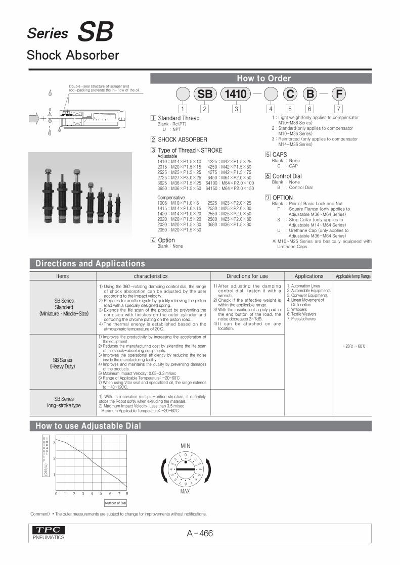
Series SBShock Absorber
How to Order
Directions and Applications
1 2 3
SB 14104 5
� Standard ThreadBlank : Rc(PT)
U : NPT
� SHOCK ABSORBER
� Type of Thread×STROKEAdjustable1410 : M14×P1.5×10 4225 : M42×P1.5×252015 : M20×P1.5×15 4250 : M42×P1.5×502525 : M25×P1.5×25 4275 : M42×P1.5×752725 : M27×P3.0×25 6450 : M64×P2.0×503625 : M36×P1.5×25 64100 : M64×P2.0×1003650 : M36×P1.5×50 64150 : M64×P2.0×150
Compensative1006 : M10×P1.0×6 2525 : M25×P2.0×251415 : M14×P1.0×15 2530 : M25×P2.0×301420 : M14×P1.0×20 2550 : M25×P2.0×502020 : M20×P1.5×20 2580 : M25×P2.0×802030 : M20×P1.5×30 3680 : M36×P1.5×802050 : M20×P1.5×50
� OptionBlank : None
1 : Light weight(only applies to compensator M10~M36 Series)
2 : Standard(only applies to compensator M10~M36 Series)
3 : Reinforced (only applies to compensator M14~M36 Series)
� CAPSBlank : None
C : CAP
� Control DialBlank : None
B : Control Dial
� OPTIONBlank : Pair of Basic Lock and Nut
F : Square Flange (only applies toAdjustable M36~M64 Series)
S : Stop Collar (only applies toAdjustable M14~M64 Series)
U : Urethane Cap (only applies toAdjustable M36~M64 Series)
※ M10~M25 Series are basically equipeed withUrethane Caps.
C6
B7
F
1) Using the 360'-rotating damping control dial, the rangeof shock absorption can be adjusted by the useraccording to the impact velocity.
2) Prepares for another cycle by quickly retrieving the pistonroad with a specially designed spring.
3) Extends the life span of the product by preventing thecorrosion with finishes on the outer cylinder andcorroding the chrome plating on the piston road.
4) The thermal energy is established based on theatmospheric temperature of 20'C.
Items
SB SeriesStandard
(Miniature∙Middle-Size)
SB Series(Heavy Duty)
SB Serieslong-stroke type
characteristics Directions for use Applications Applicable temp Range
1) Improves the productivity by increasing the acceleration ofthe equipment.
2) Reduces the manufacturing cost by extending the life spanof the shock-absorbing equipments.
3) Improves the operational efficiency by reducing the noiseinside the manufacturing facility.
4) Improves and maintains the quality by preventing damagesof the products.
5) Maximum Impact Velocity: 0.05~3.3 m/sec6) Range of Applicable Temperature: -20~60'C7) When using Vitar seal and specialized oil, the range extends
to -40~120'C.
1) With its innovative multiple-orifice structure, it definitelystops the Robot softly when extruding the materials. 2) Maximum Impact Velocity: Less than 3.5 m/sec Maximum Applicable Temperature: -20~60'C
1) After adjusting the dampingcontrol dial, fasten it with awrench.
2) Check if the effective weight iswithin the applicable range.
3) With the insertion of a poly pad inthe end button of the road, thenoise decreases 3~7dB.
4) It can be attached on anylocation.
1. Automation Lines2. Automobile Equipments3. Conveyor Equipments4. Linear Movement of
Oil Insertion5. Wrappers6. Textile Weavers7. Press/adherers
-20℃ ~ 60℃
Comment) �The outer measurements are subject to change for improvements without notifications.
How to use Adjustable Dial

A - 467PNEUMATICS
Series SB
ACP
UACP
AX
AS
AM2
AM
ALALX
ARD
AQ
AQ2
AJ
AG
AGXGX
AST
NLCD
NLCS
NF
NR
ASL
CR/CV
SB
SAH
TPC
W~
AMR
ADM
ADR
Model A B C ∅D E F ∅G MStroke
SB1410-CB
SB2015-CB
SB2525-CB
SB2725-CB
10
15
25
25
93
127
166
166
4
6
8
8
17
24
32
32
19.6
27.7
37
37
15
21
26
28
18
23
31
31
26
35
40
40
70.5
97.5
126.5
126.5
10
15
25
25
4
6
8
8
20
22
24
24
4
6
8
8
11
17
20
20
M14×P1.5
M20×P1.5
M25×P1.5
M27×P3.0
M14×P1.5
M20×P1.5
M25×P1.5
M27×P3.0
L/N, S/C, S/F H I J D1 D2 L
SB1410-CB
SB2015-CB
SB2525-CB
SB2725-CB
K
Model
SB1410-CB
SB2015-CB
SB2525-CB
SB2725-CB
10
15
25
25
5
14
75
75
24.500
35.000
70.000
70.000
0.3~102
1.3~285
9.8~1550
9.8~1550
680
1160
3800
3800
5~11
8~15
15~45
15~45
65
150
340
390
L/N
S/C
Comment) �The outer measurements are subject to change for improvements without notifications.
SB Series [Miniature]
Dimension & Capacity Chart
Construction
Parts List
unit: mm
No
�
�
�
�
�
�
�
�
Description
Adjustable Dial
Stopping Ring
Adjustable Rod
End Packing
Adjustable Tube
Steel ball
Inner Tube
Return Sprin
Material
Carbon Steel
Carbon Steel
Carbon Steel
NBR
Special Steel
Bearing Steel
Special Steel
Spring Steel
Note
Black coating
Black coating
Black coating
Heat treatment
No
�
�
�
�
�
�
�
�
�
�
�
Description
Lock Nut
Housing
Piston
Packing Holder
Accumulator
Top Packing
Rod Packing
Dust Cap
Piston Rod
Button
Cap
Material
Carbon Steel
Rolling Steel
Copper Ally
Copper Ally
Special Rubber
NBR
Special Rubber
Al + Acetal
Special Steel
Special Steel
Special urethane
Note
Black coating
Foaming Rubber
Hard Cr Plating
Black coating
SStroke
(mm)
EC
Total Energy[MAX](Nm)
ED
Thalmal Energy[MAX]
(Nm/h)
WE
Effective Weight[MIN] [MAX]
(N)
FImpact Force
(N)
Return Force[MIN] [MAX]
(N)
Mass
(g)

A - 468PNEUMATICS
Series SB
Comment) �No ③~⑧ is for Adjustable dial of Heavy duty.�The outer measurements are subject to change for improvements without notifications.
unit: mm
Model A B C ∅D E F ∅G MStroke
SB3625-CB
SB3650-CB
25
50
182
232
10
10
46
46
53.1
53.1
37
37
45
45
60
60
45
45
32
32
9
9
6
6
133
158
25
50
10
10
26
26
10
10
34
34
M36×P1.5
M36×P1.5
M36×P1.5
M36×P1.5
L/N, S/C, S/F H I J D1 D2 L a b c d
SB3625-CB
SB3650-CB
K
Model
SB3625-CB
SB3650-CB
25
50
120
240
90.000
110.000
17~2450
34~4900
6000
6000
40~75
25~60
680
780
L/N
S/C
S/F
SB Series (Middel Size)
Dimension & Capacity Chart
Parts List
Construction
No
�
�
③
④
⑤
⑥
⑦
⑧
�
�
Description
End Rod
End Packing
Adjustable Spring
Inner Tube
Accumulator
Adjustable Dial
Housing
Adjustable Tube
Piston
Top Packing
Material
Carbon Steel
NBR
Spring Steel
Special Steel
Special Rubber
Carbon Steel
Rolling Steel
Special Steel
Copper Ally
NBR
Note
Black coating
Heat treatment
Foaming Rubber
Black coating
Black coating
No
�
�
�
�
�
�
�
�
�
Description
Packing Holder
Rod Packing
Dust Cap
Bearing
Dust Seal
Piston Rod
Return Spring
Button
Cap
Material
Copper Ally
Special Rubber
Al + Acetal
Standard
NBR
Special Steel
Spring Steel
Carbon Steel
Special urethane
Note
Black coating
Hard Cr Plating
Hard Cr Plating
Black coating
SStroke
(mm)
EC
Total Energy[MAX](Nm)
ED
Thalmal Energy[MAX]
(Nm/h)
WE
Effective Weight[MIN] [MAX]
(N)
FImpact Force
(N)
Return Force[MIN] [MAX]
(N)
Mass
(g)

A - 469PNEUMATICS
Series SB
ACP
UACP
AX
AS
AM2
AM
ALALX
ARD
AQ
AQ2
AJ
AG
AGXGX
AST
NLCD
NLCS
NF
NR
ASL
CR/CV
SB
SAH
TPC
W~
AMR
ADM
ADR
Comment) �The outer measurements are subject to change for improvements without notifications.
Model A B C D E ∅F G ∅H ∅I J MStroke
SB4225-CB
SB4250-CB
SB4275-CB
SB6450-CB
SB64100-CB
SB64150-CB
25
50
75
50
100
150
167
217
267
241
341
471
54
75
10
16
58
75
44
60
48
60
60
90
41.5
70
12
16
9
10
152
202
252
224
324
454
94
119
144
138
188
238
32
44
56
50
76
76
29
42
55
49
75
75
14
14
14
20
20
20
49
61.5
74
67.5
95
141
45
45
45
58
58
58
38
38
38
50
50
50
54
54
54
75
75
75
M42×P1.5
M42×P1.5
M42×P1.5
M64×P2.0
M64×P2.0
M64×P2.0
M42×P1.5
M64×P2.0
L/N, S/C, S/F J C D2 D1 L a b c d
SB42**-CB
SB64**-CB
K
Model
SB4225-CB
SB4250-CB
SB4275-CB
SB6450-CB
SB64100-CB
SB64150-CB
25
50
75
50
100
150
250
500
750
1250
2550
3750
130000
157500
195000
245000
335000
370000
25 3600
45 6100
55 9100
70 13000
115 17500
130 23500
2400
2400
2400
3300
3300
3300
50 85
35 75
35 100
80 165
75 210
95 360
1000
1300
1600
3500
4700
6100
L/N
S/C
S/F
SB Series (Heavy Duty)
Dimension & Capacity Chart
How to use adjustable dial
unit: mm
SStroke
(mm)
EC
Total Energy[MAX](Nm)
ED
Thalmal Energy[MAX]
(Nm/h)
WE
Effective Weight[MIN] [MAX]
(N)
FImpact Force
(N)
Return Force[MIN] [MAX]
(N)
Mass
(g)
K
K
L
H
b c
4-∅d
A
B
C
D E
GM
∅J
∅D1
I∅ H∅
∅F
∅D2
a
J
A - 470PNEUMATICS
Series SB
Comment) �The outer measurements are subject to change for improvements without notifications.
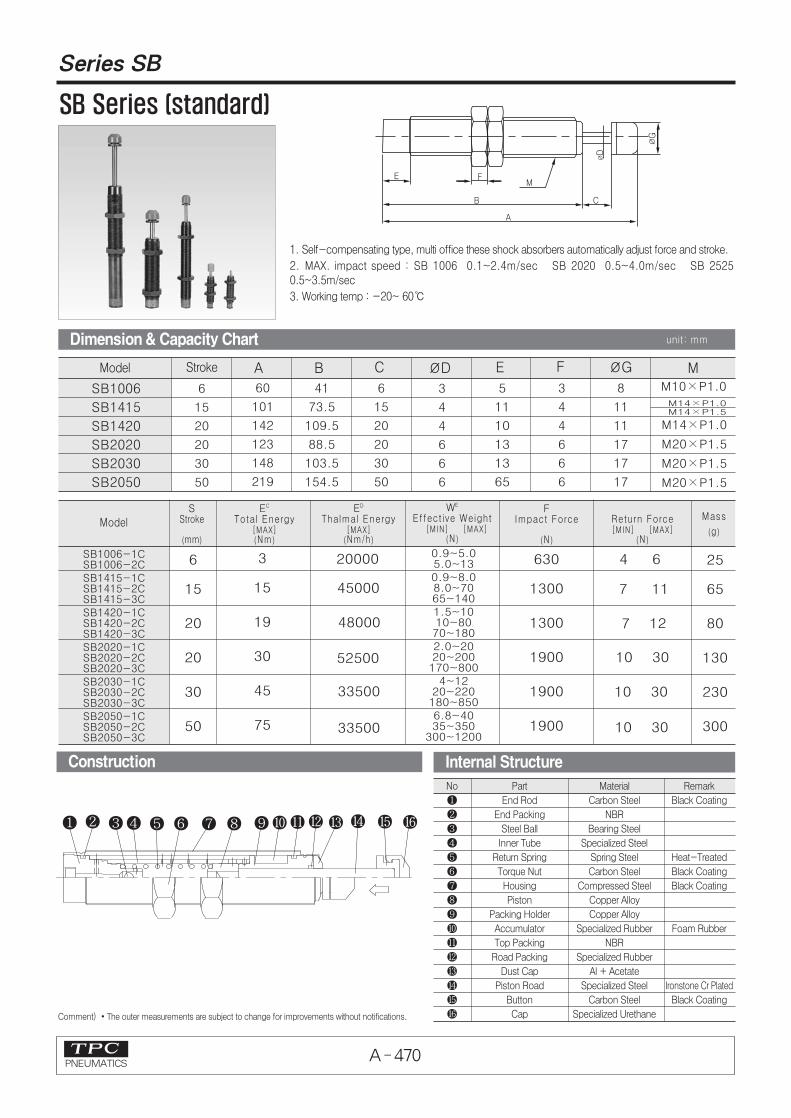
Model A B C ∅D E F ∅G MStroke
SB1006
SB1415
SB1420
SB2020
SB2030
SB2050
6
15
20
20
30
50
60
101
142
123
148
219
41
73.5
109.5
88.5
103.5
154.5
6
15
20
20
30
50
M10×P1.0
M14×P1.0
M20×P1.5
M20×P1.5
M20×P1.5
ModelS
Stroke
(mm)
EC
Total Energy[MAX](Nm)
ED
Thalmal Energy[MAX]
(Nm/h)
WE
Effective Weight[MIN] [MAX]
(N)
FImpact Force
(N)
Return Force[MIN] [MAX]
(N)
Mass
(g)
SB1006-1CSB1006-2CSB1415-1CSB1415-2CSB1415-3CSB1420-1CSB1420-2CSB1420-3CSB2020-1CSB2020-2CSB2020-3CSB2030-1CSB2030-2CSB2030-3CSB2050-1CSB2050-2CSB2050-3C
0.9~5.05.0~130.9~8.08.0~7065~1401.5~1010~8070~1802.0~2020~200170~800
4~1220~220180~8506.8~4035~350
300~1200
6
15
20
20
30
50
3
15
19
30
45
75
20000
45000
52500
48000
33500
33500
630
1300
1300
1900
1900
1900
25
65
80
130
230
300
4 6
7 11
10 30
10 30
7 12
10 30
3
4
4
6
6
6
5
11
10
13
13
65
3
4
4
6
6
6
8
11
11
17
17
17
M14×P1.0M14×P1.5
SB Series (standard)
Construction
Dimension & Capacity Chart unit: mm
1. Self-compensating type, multi office these shock absorbers automatically adjust force and stroke.
2. MAX. impact speed : SB 1006 0.1~2.4m/sec SB 2020 0.5~4.0m/sec SB 25250.5~3.5m/sec
3. Working temp : -20~ 60℃
Internal Structure
No
�
�
�
�
�
�
�
�
�
�
�
�
�
�
�
�
Part
End Rod
End Packing
Steel Ball
Inner Tube
Return Spring
Torque Nut
Housing
Piston
Packing Holder
Accumulator
Top Packing
Road Packing
Dust Cap
Piston Road
Button
Cap
Material
Carbon Steel
NBR
Bearing Steel
Specialized Steel
Spring Steel
Carbon Steel
Compressed Steel
Copper Alloy
Copper Alloy
Specialized Rubber
NBR
Specialized Rubber
Al + Acetate
Specialized Steel
Carbon Steel
Specialized Urethane
Remark
Black Coating
Heat-Treated
Black Coating
Black Coating
Foam Rubber
Ironstone Cr Plated
Black Coating
A - 471PNEUMATICS
Series SB
ACP
UACP
AX
AS
AM2
AM
ALALX
ARD
AQ
AQ2
AJ
AG
AGXGX
AST
NLCD
NLCS
NF
NR
ASL
CR/CV
SB
SAH
TPC
W~
AMR
ADM
ADR
Comment) �The outer measurements are subject to change for improvements without notifications.
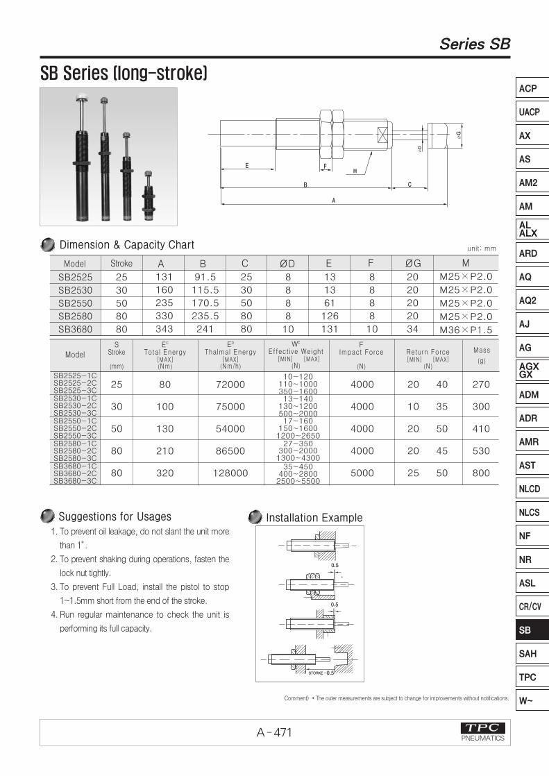
1. To prevent oil leakage, do not slant the unit more
than 1。.
2. To prevent shaking during operations, fasten the
lock nut tightly.
3. To prevent Full Load, install the pistol to stop
1~1.5mm short from the end of the stroke.
4. Run regular maintenance to check the unit is
performing its full capacity.
Installation Example
unit: mm
Model A B C ∅D E F ∅G MStroke
SB2525
SB2530
SB2550
SB2580
SB3680
25
30
50
80
80
131
160
235
330
343
91.5
115.5
170.5
235.5
241
25
30
50
80
80
8
8
8
8
10
13
13
61
126
131
8
8
8
8
10
20
20
20
20
34
M25×P2.0
M25×P2.0
M25×P2.0
M25×P2.0
M36×P1.5
Dimension & Capacity Chart
Model
SB2525-1CSB2525-2CSB2525-3CSB2530-1CSB2530-2CSB2530-3CSB2550-1CSB2550-2CSB2550-3CSB2580-1CSB2580-2CSB2580-3CSB3680-1CSB3680-2CSB3680-3C
10~120110~1000350~160013~140
130~1200500~200017~160
150~16001200~2650
27~350300~20001300~4300
35~450400~28002500~5500
25
30
50
80
80
80
100
130
210
320
72000
75000
54000
86500
128000
4000
4000
4000
4000
5000
20 40
10 35
20 50
20 45
25 50
270
300
410
530
800
SB Series (long-stroke)
SStroke
(mm)
EC
Total Energy[MAX](Nm)
ED
Thalmal Energy[MAX]
(Nm/h)
WE
Effective Weight[MIN] [MAX]
(N)
FImpact Force
(N)
Return Force[MIN] [MAX]
(N)
Mass
(g)
Suggestions for Usages

A - 472PNEUMATICS
Series SB
Adjustable SB (Miniature)SB1410~2725 Series
Non-Adjustable SB (Standard)SB1006~2525 Series
Non-Adjustable SB (Long-Stroke type)
SB2030~3680 Series
Adjustable SB (Mid size)SB3625~3650 Series
Adjustable SB (Heavy Duty)SB4225~64150 Series
Note) �The size is subject to be changed for improve capacity without pre-notice.
Series
Shock Absorber
A - 473PNEUMATICS
Series SB
ACP
UACP
AX
AS
AM2
AM
ALALX
ARD
AQ
AQ2
AJ
AG
AGXGX
AST
NLCD
NLCS
NF
NR
ASL
CR/CV
SB
SAH
TPC
W~
AMR
ADM
ADR
Comment) �The outer measurements are subject to change for improvements without notifications.
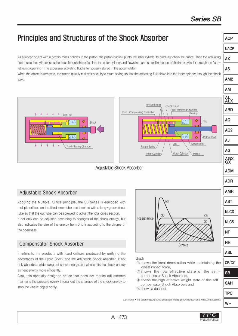
As a kinetic object with a certain mass collides to the piston, the piston backs up into the inner cylinder to gradually chain the orifice. Then the activating
fluid inside the cylinder is pushed out through the orifice into the outer cylinder and flows into and stored in the top of the inner cylinder through the fluid-
retrieving opening. The excessive activating fluid is temporarily stored in the accumulator.
When the object is removed, the piston quickly retrieves back by a return spring so that the activating fluid flows into the inner cylinder through the check
valve.
Applying the Multiple-Orifice principle, the SB Series is equipped with
multiple orifices on the fixed inner tube and inserted with a long-grooved out
tube so that the out tube can be screwed to adjust the total cross section.
It not only can be adjusted according to changes of the shock energy, but
also indicates the size of the energy from 0 to 8 according to the degree of
the openness.
Adjustable Shock Absorber
It refers to the products with fixed orifices produced by unifying the
advantages of the Hydro Shock and the Adjustable Shock Absorber. It not
only absorbs a wider range of shock energy, but also emits the shock energy
as heat energy more efficiently.
Also, this specially designed orifice that does not require adjustments
maintains the pressure evenly throughout the changes of the shock energy to
stop the kinetic object softly.
Principles and Structures of the Shock Absorber
Graph① shows the ideal deceleration while maintaining the
lowest impact force,② shows the low effective state of the self-
compensator Shock Absorbers, ③ shows the high effective weight state of the self-
compensator Shock Absorbers and ④ shows a dashpot.
Adjustable Shock Absorber
Compensator Shock Absorber
A - 474PNEUMATICS
Series SB
Comment) �The outer measurements are subject to change for improvements withoutnotifications.
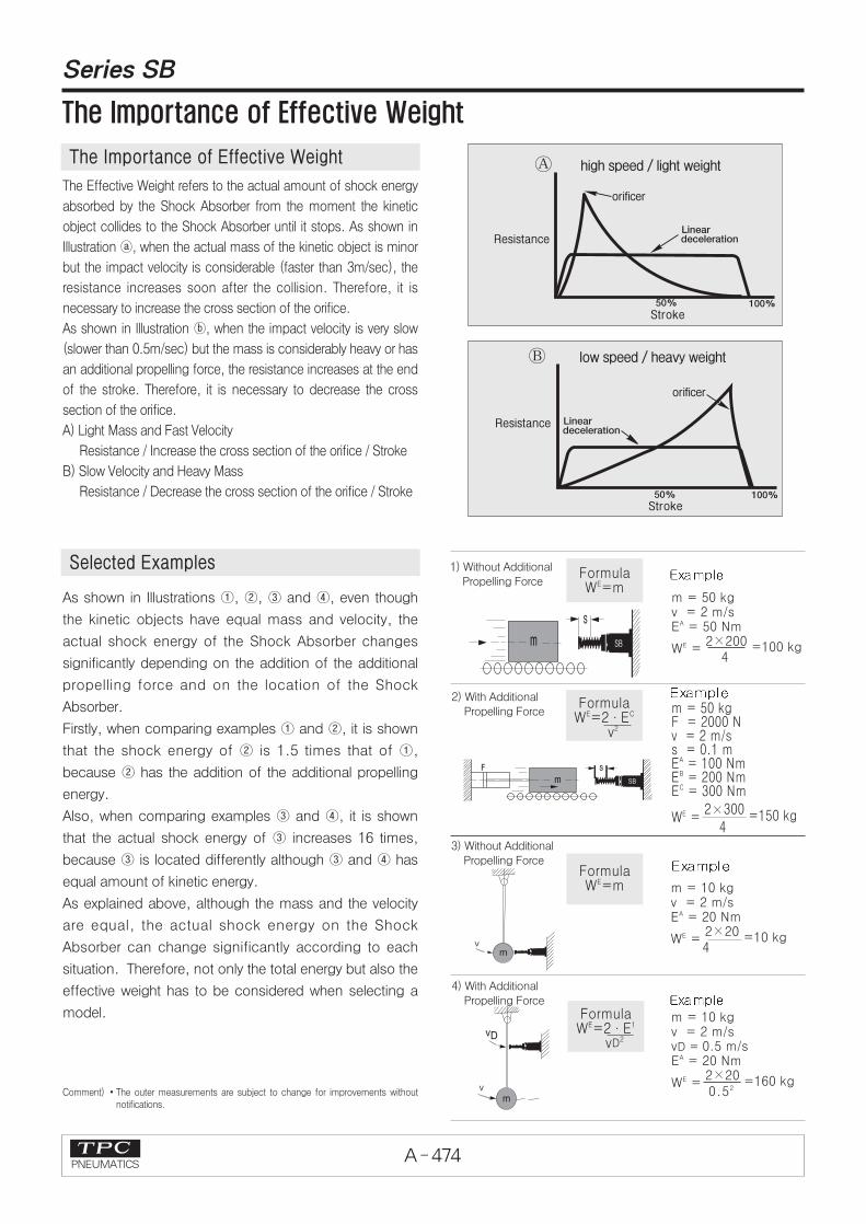
The Effective Weight refers to the actual amount of shock energy
absorbed by the Shock Absorber from the moment the kinetic
object collides to the Shock Absorber until it stops. As shown in
Illustration ⓐ, when the actual mass of the kinetic object is minor
but the impact velocity is considerable (faster than 3m/sec), the
resistance increases soon after the collision. Therefore, it is
necessary to increase the cross section of the orifice.
As shown in Illustration ⓑ, when the impact velocity is very slow
(slower than 0.5m/sec) but the mass is considerably heavy or has
an additional propelling force, the resistance increases at the end
of the stroke. Therefore, it is necessary to decrease the cross
section of the orifice.
A) Light Mass and Fast Velocity
Resistance / Increase the cross section of the orifice / Stroke
B) Slow Velocity and Heavy Mass
Resistance / Decrease the cross section of the orifice / Stroke
As shown in Illustrations ①, ②, ③ and ④, even though
the kinetic objects have equal mass and velocity, the
actual shock energy of the Shock Absorber changes
significantly depending on the addition of the additional
propelling force and on the location of the Shock
Absorber.
Firstly, when comparing examples ① and ②, it is shown
that the shock energy of ② is 1.5 times that of ①,
because ② has the addition of the additional propelling
energy.
Also, when comparing examples ③ and ④, it is shown
that the actual shock energy of ③ increases 16 times,
because ③ is located differently although ③ and ④ has
equal amount of kinetic energy.
As explained above, although the mass and the velocity
are equal, the actual shock energy on the Shock
Absorber can change significantly according to each
situation. Therefore, not only the total energy but also the
effective weight has to be considered when selecting a
model.
1) Without AdditionalPropelling Force
m = 50 kgv = 2 m/sEA = 50 Nm
WE = 2×200 =100 kg
4
FormulaWE=m
2) With AdditionalPropelling Force
m = 10 kgv = 2 m/svD = 0.5 m/sEA = 20 Nm
WE = 2×20 =160 kg0.52
m = 10 kgv = 2 m/sEA = 20 Nm
WE = 2×20 =10 kg4
m = 50 kgF = 2000 Nv = 2 m/ss = 0.1 mEA = 100 NmEB = 200 NmEC = 300 Nm
WE = 2×300 =150 kg
4
FormulaWE=2∙EC
v2
FormulaWE=2∙E1
vD2
FormulaWE=m
�
�
The Importance of Effective Weight
Selected Examples
The Importance of Effective Weight
3) Without AdditionalPropelling Force
4) With AdditionalPropelling Force

A - 475PNEUMATICS
Series SB
ACP
UACP
AX
AS
AM2
AM
ALALX
ARD
AQ
AQ2
AJ
AG
AGXGX
AST
NLCD
NLCS
NF
NR
ASL
CR/CV
SB
SAH
TPC
W~
AMR
ADM
ADR
Comment) �The outer measurements are subject to change for improvements without notifications.
Four Elements for Selecting Models
Calculation Formula
Details of Applications
1
2
3
4
Weight
Impact velocity
Propelling force
Cycle per hour
m (kg)
V (m/sec)
F (N)
C (cycle/hour)
Step 1
Step 2
Step 3
Step 4
Step 5
Kinetic Energy EA=m∙v2/2
Work Energy EB=F∙S
Total Energy EC=EA +EB
Thalmal Energy ED=(EA +EB) C
Effective Weight WE=2∙EC / V2
Group 1 model assumption
Group 2 model assumption
Final model selection
EA Kinetic Energy : Kinetic Energy (Nm)
EB Work Energy : Work Energy (Nm)
EC Total Energy : Total Energy (Nm)
ED Thalmal Energy : Thamal Energy (Nm/hr)
WE Effective Weight : Effective Weight (Kg)
m Weight : mass (Kg)
v Impact velocity : velocity (m/s)
VD impact velocity (m/s)
F Propelling force : propelling force (N)
C Cycle per hour : cycle per hour (cycle/hr)
P motor power (kw)
1. Horizontal movement addition (without propelling force)
2. Horizontal movement addition(with propelling force)
3. Horizontal movement (when operatingan electromotive motor)
ST Stall torque factor 1 to 2.5 (2.5)
M Propelling troque (Nm)
g Acceleration of gravity (m/s2)
h Actual drop height (m)
L/R/r Radius (m)
Q Reaction force (N)
u Friction coefficient
t deceleration time (sec)
g”s deceleration rate (g”s)
s stroke (m)
1N = 0.102 kg, 1kg = 9.81 N1Nm = 0.102kg.m 1kg.m = 9.81 Nm
Calculation formulas
EA = 0.5∙m∙v2
EB = zeroEC = EA+ EB
ED = EC∙C
WE = 2∙EC
=mv2
Calculation formulas
EA = 0.5∙m∙v2
EB = F∙sEC = EA+ EB
ED = EC∙C
WE = 2∙EC
v2
Calculation formulas
EA = 0.5∙m∙v2
EB = 1000∙P∙ST∙sV
EC = EA+ EB
ED = Ec∙C
WE = 2∙EC
v2
EA = 0.5×150×22 =300Nm
EB = 300+0 =300Nm
ED = 300×400 =120.000Nm
WE = m =150kg
m= 150 kg
V = 2 m/s
C = 400 /hr
m= 250 kg
V = 1.5 m/s
F = 1000 N
C = 300 /hr
S = 0.05 m
capacity chart model : SB4250-CB
EA = 0.5×250×1.52 =281.25Nm
EB = 1000×0.05 =50Nm
EC = 281.25+50 =331.25Nm
ED = 331.25×300 =99.375Nm/hr
WE = 2×331.25÷1.52 = 294.4kg
capacity chart model : SB3650-CB
m= 700 kg
V = 1.5 m/s
ST= 2.5
P = 6 kw
C = 200 /hr
S = 0.1m
EA = 0.5×700×1.52 =788Nm
EB = 1000×6×2.5×0.1÷1.5=1000Nm
EC = 788+1000 =1788Nm
ED = 1788×200 =357.600Nm/hr
WE = 2×1788÷1.52 = 1589kg
capacity chart model : SB64150-CB
How to Select

A - 476PNEUMATICS
Series SB
4. Horizontal Movement(Power Roller Free)
5. Horizontal Rotational Movement(With additional propelling force)
6. Vertical Movement(Free Fall)
7. Free Fall on slopes
8. Index Table(When operating N)
9. Horizontal Rotational Movement (When operating N)
10. Vertical Movement(With propelling force)
※ When a special safely Illustration is needed, add a compensator constant.
Calculation formulas
EA = 0.5∙m∙v2
EB = u∙m∙g∙sEC = EA+ EB
ED = EC∙C
WE = 2∙EC
v2
Calculation formulas
EA = m∙g∙hEB = m∙g∙sEC = EA+ EB
ED = EC∙CVD = 2∙g∙h
WE = 2∙EC
vD2
Calculation formulas
EA = 0.5∙m∙v2
EB = m∙g∙sEC = EA+ EB
ED = EC∙C
WE = 2∙EC
v2
Calculation formulas
EA = 0.5∙m∙v2
EB = M∙sR
EC = EA+ EB
ED = EC∙CVD = V∙R
L
WE = 2∙EC
vD2
Calculation formulas
EA = m∙g∙hEB = m∙g∙sinα∙sEC = EA+ EB
ED = EC∙CVD = 2∙g∙h
WE = 2∙EC
vD2
Calculation formulas
EA = 0.25∙m∙v2
EB = M∙sR
EC = EA+ EB
ED = EC∙C
vD = V∙R
L
Calculation formulas
EA = 0.5∙m∙(v∙0.6)2
EB = M∙sR
EC = EA+ EB
ED = EC∙C
vD = V∙R
LWE = 2∙EC
VD2
EA = 0.5×100×1.52 =113Nm
EB = 0.2×100×9.81×0.1=20Nm
EC = 113+20 =133Nm
ED = 133×200 =26.600Nm/hr
WE = 2×133÷1.52 = 118kg
capacity chart model : SB2525-CB
capacity chart model : SB2525-CB
EA = 100×9.81×0.5=490Nm
EB = 100×9.81×0.1=98Nm
EC = 490+98 =588Nm
ED = 588×50 =29.400Nm/hr
VD = 2×9.81×0.5 = 3.13m/s
WE = 2×588÷3.132 = 120kg
capacity chart model : SB2525-2C
EA = 100×9.81×1=981Nm
EB = 100×9.81×0.5×0.1=49Nm
EC = 981+49 =1030Nm
ED = 1030×100 =103.000Nm/hr
VD = 2×9.81×1 = 4.5m/s
WE = 2×1030÷4.52 = 1.017kg
capacity chart model : SB3625-CB
EA = 0.25×400×1.52 =225Nm
EB = 2000×0.05÷1=100Nm
EC = 225+100 =325Nm
ED = 325×150 =32.500Nm/hr
VD = 1.5×1÷1.5 = 1m/s
WE = 2×325÷12 = 650kg
capacity chart model : SB2525-CB/SB2525-2C
EA = 0.5×250×(1.5×0.6)2 =101Nm
EB = 2000×0.03÷1.5=40Nm
EC = 101+40=141Nm
ED = 141×1000=141.000Nm/hr
VD = 1.5×1.5÷1.5=1.5m/s
WE = 2×141÷1.52=125kg
capacity chart model : SB4250-CB
EA = 0.5×800×12 =400Nm
EB = 800×9.81×0.15=1177Nm
EC = 400+1177=1577Nm/hr
ED = 1577×10=15.770Nm/hr
WE = 2×1577÷12=3154kg
capacity chart model : SB4250-CB
m= 100 kg
V = 1.5 m/s
C = 200 /hr
S = 0.1m
U = 0.2 (steel/steel)
m= 50 kg
V = 1.5 m/s
R = 0.5 m
C = 200 /hr
L = 1 m
S = 0.03 m
m= 100 kg
h = 0.5 m
M = 100 N/m
C = 50 /hr
S = 0.1m
m= 100 kg
h = 1 m
α= 30。
C = 100 /hr
S = 0.1m
m= 400 kgV = 1.5 m/sM = 2000 N/mS = 0.05mL = 1 m
R = 1 m
C = 150 /hr
m= 250 kgV = 1.5 m/sM = 2000 N/mS = 0.03mL = 1.5 m
R = 1.5 m
C = 1000 /hr
m= 800 kgV = 1 m/sS = 0.15mC = 10 /hr
EA = 0.5×50×1.52 =56Nm
EB = 100×0.03÷0.5=6Nm
EC = 56+6 =62Nm
ED = 62×200 =12.400Nm/hr
VD = 1.5×0.5÷1 = 0.75m/s
WE = 2×62÷0.752 = 220kg
A - 477PNEUMATICS
Series SB
ACP
UACP
AX
AS
AM2
AM
ALALX
ARD
AQ
AQ2
AJ
AG
AGXGX
AST
NLCD
NLCS
NF
NR
ASL
CR/CV
SB
SAH
TPC
W~
AMR
ADM
ADR
Precautions
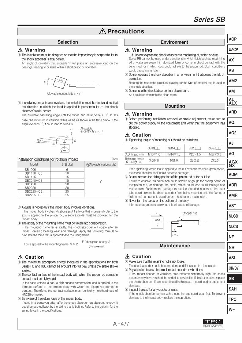
Warning① The installation must be designed so that the impact body is perpendicular to
the shock absorber’s axial center. An angle of deviation that exceeds 1。will place an excessive load on thebearings, leading to oil leaks within a short period of operation.
② If oscillating impacts are involved, the installation must be designed so thatthe direction in which the load is applied is perpendicular to the shockabsorber’s axial center. The allowable oscillating angle until the stroke end must be θ2 < 1。. In this
case, the minimum installation radius will be as shown in the table below. If theangle exceeds 1。, it could lead to oil leaks.
Installation conditions for rotation impact
③ A guide is necessary if the impact body involves vibrations.If the impact body involves vibrations and if a force that is perpendicular to theaxis is applied to the piston rod, a secure guide must be provided for theimpact body.
④ The rigidity of the mounting frame must be taken into consideration.If the mounting frame lacks rigidity, the shock absorber will vibrate after animpact, causing bearing wear and damage. Apply the following formula tocalculate the force that is applied to the mounting frame:
Caution① The maximum absorption energy indicated in the specifications for both
Series RB and RBL cannot be brought into full play unless the entire strokeis used.
② The contact surface of the impact body with which the piston rod comes incontact must be highly rigid.In the case whthout a cap, a high surface compression load is applied to thecontact surface of the impact body with which the piston rod comes incontact. Therefore, the contact surface must be highly rigid(hardness ofHRC35 or more).
③ Be aware of the retum force of the impact body. If used in a conveyou drive, affer the shock absorber has absorbed energy, itcould be pushed back by the spring that is built in. Refer to the column for thespring force in the specifications.
Caution① Make sure that the retaining nut is not loose.
The shock absorber could become damaged if it is used in a loose state.
② Pay attention to any abnormal impact sounds or vibrations.If the impact sounds or vibrations have become abnormally high, the shockabsorber may have reached the end of its service life. If this is the case, replacethe shock absorber. If use is continued in this state, it could lead to equipmentdamage.
③ Inspect the cap for any cracks or wear.If the shock absorber comes with a cap, the cap could wear first. To preventdamage to the impact body, replace the cap often.
Warning① Do not expose the shock absorber to machining oil, water, or dust.
Series RB cannot be used under conditions in which fluids such as machiningoil or water are present in atomized form or come in direct contact with thepiston rod, or in which dust could adhere to the piston rod. Such conditions
would cause malfunction.
② Do not operate the shock absorber in an environment that poses the risk of corrosion.Refer to the respective structural drawing for the type of material that is used inthe shock absorbar.
③ Do not use the shock absorber in a clean room.As it could contaminate the clean room.
Warning① Before perfoming installation, removal, or stroke adjustment, make sure to
cut the power supply to the equipment and verify that the equipment hasstopped.
Caution① Tightening torque of mounting nut should be as follows.
If the tightening torque that is applied to the nut exceeds the value given above,the shock absorber itself could become damaged.
② Do not scratch the sliding portion of the piston rod or the outside.Failure to observe this precaution could scratch or gouge the sliding potion ofthe piston rod, or damage the seals, which could lead to oil leakage andmalfunction. Furthermore, damage to outside threaded portion of the outertube could prevent the shock absorber from being mounted onto the frame, orits intermal components could deform, leading to a malfunction.
③ Never turn the screw on the bottom of the body.It is not an adjustment screw, as this will cause oil leakage.
Model
SB1006SB1410-CBSB1415SB2015-CBSB1420SB2020SB2525-CBSB2725-CB
610151520202525
l。
S(Stroke) θ2(Allowable rotation angle)
(mm)
Force applied to the mounting frame N ≒ 2E (absorption energy J)
S (stroke m)
EnvironmentSelection
Mounting
Maintenance
Model
O.D.thread mm M10×1.0
3.0(0.3)
M14×1.5
10(1.0)
M20×1.5
23(2.3)
M27×3.0
63(6.3)Tightening torqueN∙m(kgf∙m)
SB10�� SB14�� SB20�� SB27��