series 9000mp multipoint system series 9600mp system ... · the epi series 9000mp multipoint...
TRANSCRIPT

Master-Touch™ version 5.0A
Series 9000MP Multipoint System
Series 9600MP System Control Panel
Thermal Gas Mass Flowmeters
INSTRUCTION MANUAL 80201501 (Rev. 3)


www.epiflow.com
Eldridge Products, Inc. 465 Reservation Road
Marina, CA 93933
Tel: 800/321-3569
or 831/648-7777
Fax: 831/648-7780
Email: [email protected]
Copyright © 2014 by Eldridge Products, Inc. All Rights Reserved.


Table of Contents
Section A Introduction and Installation .............................................................. A–1
Unpacking Your Instrument ...................................................................................................................... A–1
Getting Acquainted ................................................................................................................................... A–1
Section B General Information ............................................................................. B-1
Construction ............................................................................................................................................... B-1
Sensitivity and Accuracy ............................................................................................................................ B-1
Probe Configuration ................................................................................................................................... B-1
Field Testing .............................................................................................................................................. B-1
System Control Panel ................................................................................................................................ B-2
Installation And Mounting .......................................................................................................................... B-2
Series 9600MP Power Requirements ....................................................................................................... B-3
Series 9000MP Power Requirements ....................................................................................................... B-3
Signal Interface .......................................................................................................................................... B-3
Section C The Master-Touch™ LCD and Key Pad .............................................. C-1
100 *Meter* Menu ...................................................................................................................................... C-2 100 *Meter* Submenus ...................................................................................................................................... C-2
200 *Utility* Menu ...................................................................................................................................... C-4 200 *Utility* Submenus ...................................................................................................................................... C-4
300 *Status* Menu ..................................................................................................................................... C-8
400 *Alarms* Menu .................................................................................................................................. C-10 Alarm Relay Overview...................................................................................................................................... C-10 400 *Alarms* Submenus .................................................................................................................................. C-11 Alarm Programming ......................................................................................................................................... C-12
450 *E-Log* Menu ................................................................................................................................... C-14
700 *S-Curve Fit* Menu ........................................................................................................................... C-16 700 *S-Curve Fit* Submenus ........................................................................................................................... C-16
750 *PW-Curve Fit* Menu ....................................................................................................................... C-17 750 *PW-Curve Fit* Submenus ........................................................................................................................ C-17
800 *P-Curve Fit* Menu ........................................................................................................................... C-19 800 *P-Curve Fit* Submenus ........................................................................................................................... C-19
Section D Instructions for Specific Actions ........................................................ D-1
Unlocking the Master-Touch™ — Menu Item 219–UnLock ...................................................................... D-1
Selecting the Engineering Units — Menu Items 101–132 ......................................................................... D-3
Changing the Full Scale range — Menu Item 140–FScale ....................................................................... D-4
Resetting the Flow Rate and Flow Total — Menu Item 160–Reset! ......................................................... D-5
Adjusting the Display Rate — Menu Item 207–Disp Rate ......................................................................... D-6
Adjusting the LCD Display Contrast — Menu Item 208–Disp Set ............................................................. D-7
Setting the Alarms — Menu Items 401–414 .............................................................................................. D-8
Adjusting the C Factor — Menu Item 811–C Factor ............................................................................... D-10
Adjusting the Zero Offset — Menu Item 815–Auto Zero ......................................................................... D-11
Setting the Low Flow Cutoff — Menu Item 816–FlowCutoff.................................................................... D-13
Section E Factory Calibration .............................................................................. E-1
Section F General Specifications .........................................................................F-1
Specification Notice ................................................................................................................................... F-1
Service Work ............................................................................................................................................. F-1
Storage ...................................................................................................................................................... F-1
Limited Warranty ........................................................................................................................................ F-2
Limited Acceptance ................................................................................................................................... F-2
Section G Guidelines and Product Drawings ...................................................... G-1
Calculating Secondary Coefficients ........................................................................................................... G-1
Engineering Drawings................................................................................................................................ G-2
Example of Menu Data Sheet .................................................................................................................... G-8
Menu Item Interaction ................................................................................................................................ G-9
Master-Touch™ Diagnostics ..................................................................................................................... G-9
Master-TouchTM Auto-Ranging (External Mode) ..................................................................................... G-10
Master-TouchTM ASCII Data Stream ....................................................................................................... G-11

ELDRIDGE PRODUCTS, INC. 80201501 (Rev. 2.05a) Page A–1
Section A Introduction and Installation
Introduction
The EPI Series 9000MP Multipoint Thermal Dispersion Mass Flow meters are the net result of
almost three decades of flow metering and design experience within the instrumentation industry.
Series 9000MP Multipoint System meter products directly measure the gas molecular rate of flow,
correcting for temperature changes and being insensitive to pressure changes, resulting in a true
mass rate of flow signal. Since no corrections are required, the analog 4–20mA signal may be directly
interfaced with process or data acquisition systems. A variety of other optional communications
protocols are available, including RS485 Modbus RTU, HART, and Profibus DP.
Unpacking Your Instrument
Your Series 9000MP Multipoint Mass Flowmeter is a precision piece of electronic flow
instrumentation. Although these flowmeters are rugged, they should be inspected upon delivery to
assure that no damage has taken place during transit. If upon inspection it is found that damage has
occurred, notify the carrier immediately, and place a claim for damaged goods. The shipping
container or crate should be handled with care and carefully opened, to avoid possible damage to the
contents. After the container is opened the contents should be carefully removed and the individual
pieces checked against the packing list. Should a discrepancy present itself, contact EPI shipping
department right away. The last area of verification, will be to check that the equipment and
calibration range match your purchase order specifications. If it is found that a mismatch has taken
place, contact EPI sales department to resolve any discrepancies.
Getting Acquainted
We thank you for specifying our Series 9000MP Multipoint Thermal Dispersion Mass Flowmeters.
As you know, thermal mass flow measuring devices have been around for many years and are known
for their reliability, ease of use and, most importantly, their direct readings. This equipment does not
require any peripheral devices to yield a mass rate of flow signal.
Your Series 9000MP Multipoint Mass Flowmeter product consists of two major components: the
Series 9000MP Flow Transmitter probe assembly(ies) and the Series 9600MP System Control Panel.
The Flow Transmitter probe assembly is the heart of the system. It consists of two or more flow
sensors (to a maximum of 5). Each flow sensor is constructed with thermal flow sensing elements.
The Series 9000MP Flow Transmitter probe assembly is powered by the Series 9600MP System
Control Panel over a two wire electrical connection. The Flow Transmitter sends its signal to the
System Control Panel over a 4–20mA signal loop. Our System Control Panel converts this input
signal to both 0–5 VDC & 4–20mA output signals for direct process control and/or reading. EPI
Series 9000MP Multipoint Thermal Dispersion Mass Flowmeters are designed for air/gas
measurement in ducts, stacks or other flow conduits, where two or more sensing points are required
due to large areas or where irregular flow profiles are present to net a true average flow signal
reading.


ELDRIDGE PRODUCTS, INC. 80201501 (Rev. 2.05a) Page B-1
Section B General Information
Construction
EPI Series 9000MP Multipoint Flow Transmitter probe assemblies are constructed such that all
wetted parts are 316 series stainless steel. Our probe assemblies have a continuous outside diameter
of 1.5 inches. The probe may have up to five (5) sensors per assembly. Sensors will be spaced along
the probe as specified but not closer than five (5) inches center to center. Probe assemblies greater
than 4 feet in length may require double ended support. One or more probes (12 maximum) may be
specified per duct.
Probe assemblies are fitted with a 1½" ANSI 150 lb., 316SS probe mounting flange for securing
probe assembly to user duct or stack. Attached to the outer flange surface is a fiberglass 8" x 10"
NEMA 4X (or optional NEMA 7 & NEMA 4 enclosure), housing the probe electronics.
Sensitivity and Accuracy
Each sensor is individually calibrated and linearized at the probe assembly. Series 9000MP Flow
Transmitter probes have a calibration turn down ratio of 100:1. Sensor point accuracy, including
linearity is ± [1% Reading + (.5% + .02%/°C of Full Scale)]. Repeatability is ± 0.2%. Calibration range
is to be specified by user. Gas temperatures to 300°F (temperatures to 400°F optional).
Probe Configuration
Flow Transmitter Probe Assemblies may be specified with either one sensor (probe) average output
signal or for multiple outputs to allow individual sensor readings at the Series 9600MP System
Control Panel.
Series 9000MP standard probe configuration provides that the sensors are linearized and averaged
at the probe assembly. The probe 4–20mA output signal average is transmitted to the remote Series
9600MP System Control Panel location for measurement (or averaging if required with one or more
other probe assembly signals). This method requires a four (4) wire connection per probe assembly,
(power supply positive, supply ground, 4–20mA average output and 4–20mA ground). The advantage
of this system is the low number of wire connections.
Alternatively, each sensor 4–20mA signal output may be configured for transmission to the remote
Series 9600MP System Control Panel for measurement and averaging. This method requires a wire
pair for each sensor 4–20mA signal output, power supply positive and supply ground connection. The
advantage of this system is availability of testing or reading each sensor at the remote Series
9600MP System Control Panel location.
Field Testing
Series 9000MP Flow Transmitter probe assembly sensors may be periodically tested at the probe
location to verify performance. If one or more sensor signal outputs are not functioning as required,
they may be removed from the sensor average board (located either at the Flow Transmitter Probe
Assembly or at the Series 9600MP System Control Panel) by removing the individual signal input
wire and turning off a dip switch, without affecting the system operation. One switch is on for each
active sensor on the probe.
Series 9000MP Flow Transmitter probe assembly sensors may be periodically tested at the remote
Series 9600MP System Control Panel location (if configured for individual measurement) and also at
the Flow Transmitter location if desired, to verify performance. If one or more sensor signal outputs
Instruction Manual Master-TouchTM Flowmeters
Page B-2 80201501 (Rev. 2.05a) ELDRIDGE PRODUCTS, INC.
are not functioning as required, they may be removed from the sensor average board by
disconnecting the individual signal input wire and turning off one dip switch without affecting the
system operation. One switch on the averager board is on for each active sensor on the probe
assembly.
System Control Panel
System electronics are mounted in the Series 9600MP System Control Panel’s fiberglass 16" x 14"
NEMA 4X or optional NEMA 7 enclosure remotely located from the Series 9000MP Flow
Transmitter Probe Assemblies by a few feet to thousands of feet away. Contained within the System
Control Panel enclosure are the power supply, probe average board, and sensor average boards
(when not located at the flow transmitter assembly), and option modules such as: Option 133, a 2
line by 16 character LCD readout; Option 150, a current output module driving up to 1200; or
Option 160, a sensor or probe signal profiler. Three power supplies are available to power from 1–12,
13–24 or 25–36 sensors.
If it becomes necessary to remove or replace a probe assembly from service (where two or more
probes are present), it may have it's signal input removed from the remote System Control Panel
probe averager board by removing or replacing one wire and turning off/on a dip switch without
affecting system operation. One switch is on for each Transmitter Probe Assembly input to a
maximum of twelve.
Installation And Mounting
Proper installation of the Flow Transmitter Probe Assembly is of great importance. It is important to
install the Flow Transmitter at a position where the gas is dry or above the dew point temperature.
Installations which allow large droplets of water to condense out and come in contact with the sensor
element must be avoided.
Temperature limitations of the transmitter are listed in the specification section of this manual and
show acceptable limits for the gas temperature along with the environmental temperature limits
which the transmitter electronics may be subjected to.
Avoid installations which are immediately downstream of bends, abrupt area increases or decreases,
fans, louvers, or other equipment installed in the line, etc.. These situations can cause non-uniform
flow profiles and swirl which can cause signal errors. It is desirable to have as much straight run as
possible to achieve a uniform non-swirling flow profile within the flow conduit. Rule of thumb states
that one should provide a minimum of 10 diameters of straight run upstream and 5 diameters
downstream. Although this is not always possible, it is desirable. In the event of less straight run
availability, the available length should be divided into thirds with two thirds upstream and one
third downstream. Where the installation is not ideal, more sensors should be specified.
Multipoint Flow Transmitters require the assembly be inserted through and perpendicular to the
flow conduit. The transmitter assembly is held in place by use of a 1½" flanged connection. This
flange may be mounted to a flat surface or to a mating flanged connection. The mating flange (if
required) is provided by the user or purchased as an option from EPI. Installing the mating flange
(when required) consists of preparing the flow conduit to accept the flange by first drilling a
clearance hole for the transmitter probe assembly, then welding or bolting it in place.
Mounting the Series 9600MP System Control Panel requires a flat surface or mounting rails. Four
¼" bolts are recommended with flat washers in contact with the enclosure and split lock washers
between the bolt and flat washer, to hold the enclosure firmly in place. The assembly weight will be
15 lbs. or less.
Master-TouchTM Flowmeters Instruction Manual
ELDRIDGE PRODUCTS, INC. 80201501 (Rev. 2.05a) Page B-3
Series 9600MP Power Requirements
Power requirements for the Series 9600MP System are 115 VAC 50/60 Hz standard and 220 VAC
50/60 Hz optional. A six foot power cord is provided, however, it may be removed for permanently
installed conduit wiring. If conduit is used, it should be suitable for the application, electrically
conductive and connected within the enclosure to earth ground. Our recommendation on wire size is
18 Ga. stranded for all AC wiring.
Series 9000MP Power Requirements
Flow Transmitter power requirements are met with the 18 to 24 VDC (based on loop losses and
panel adjustment) power provided by the System Control Panel. The wire should be sized for no
more than ½ resistance across the loop and not less than 22 AWG.
Signal Interface
The micro-processor provides both 0–5 Volts DC and 4–20 mA flow output signals. Voltage signals
should not be sent over long distances due to small currents causing voltage drops across the wire
pair. If the voltage is to be sent over a distance (for example 50 feet), the wire AWG should be sized
to reduce the voltage drop to acceptable levels. Knowing your load impedance is the only way this
calculation may be achieved. Our 4–20 mA signal is provided to prevent this sort of signal loss.
Current loops are normally not susceptible to noise and are not affected by voltage drops around the
loop. However, it is important when using a current loop not to exceed the level of load resistance
that the current loop may drive. Our bridge board current loop will drive a load (lead plus load
resistance) of 600 ohms for profiling. Our averager board current loop will drive a load (lead plus
load resistance) of 1200 ohms.
RS232 and RS485 connections are available for direct communication with EPICommunicator
software.


ELDRIDGE PRODUCTS, INC. 80201501 (Rev. 2.05a) Page C-1
Section C The Master-Touch™ LCD and Key Pad
Master-Touch™ flowmeters typically include a 2-line, 16-character LCD display and keypad to view
and control the functions of the full menuing system. Each of the Menus and submenu items are
accessible via the key pad, though many functions are more easily used with EPICommunicator 2.0
software. The software and the instruction manual are available for downloading at no charge from
our website, www.epiflow.com.
The illustration below shows the LCD Display when the flowmeter is in Run Mode:
Meter Range — indicates the active meter calibration range (1–4), an exclamation point (!)
indicates that the flowmeter is operating with menu item 212–Track Hold selected, a box (□)
indicates that the flow has exceeded the range of the 0–5VDC and 0–20mA output signals; a “D”
indicates that the flowmeter is running the E-Log™ mode;
Relay Status — indicates status of Relays 1 and 2 ( = de-energized, * = energized);
Infrared Aperture — allows infrared communications with EPI’s LightWIRE modules (the
blinking red light is normal);
Current Flow Rate — indicates real-time flow rate;
Engineering Units — indicates currently selected engineering units for rate and total;
Elapsed Total — indicates real-time total flow since previous reset;
Key Pad — four-button key pad for accessing microprocessor settings.
The SHIFT key selects menu items for numeric entry, moves the active character position to the left
when in numeric entry mode, and accepts or “enters” the specific numeric entry and returns the
flowmeter to the selected menu item.
The MODE key scrolls the flowmeter through the modes, and moves the active character position to
the right when in numeric entry mode.
The MAX and MIN keys work together to move “forward and backward” through the item menus
and through the numeric entry characters:
_ . / - 0 1 2 3 4 5 6 7 8 9 e + : A P M
The flowmeter must be unlocked to make changes to the variable settings. The factory
default value for menu item 219–UnLock is “9001”. If the numeric entry mode is
accessed while the flowmeter settings are still locked, the top line of the LCD display
will show “**METER LOCKED**” until you press the SHIFT key to exit the numeric
entry mode.
Instruction Manual Master-TouchTM Flowmeters
Page C-2 80201501 (Rev. 2.05a) ELDRIDGE PRODUCTS, INC.
The following pages explain the LCD displays and the presentation of flow information. For step x
step instructions to perform many of the most common adjustments to the flowmeter’s settings,
please see the following section.
100 *Meter* Menu
The 100 *Meter* Menu of the Master-Touch™ flowmeter includes a series of submenu items which
allow you to easily change the engineering units for the flow rate and elapsed total, change the
scaling of the 0–5VDC and 4–20mA output signals, and reset the stored values for elapsed total, high
and low flow rates, timestamps, etc.
The flowmeter settings must be unlocked to change the engineering units, 4-20mA
scaling or to reset the stored values (see menu item 219–UnLock).
112.3456 SCFM
9876.54321 SCF
RUN MODE
100 *Meter*
101-SCFM
Press MODE one time to advance to the 100 *Meter* menu. The display
shown at left will appear. The top line will always show you that you are in
the correct menu. The bottom line presents the specific submenu items.
The following list shows the submenus and assumes that you will use the MAX key to advance
through the submenu items. You can use MIN key to go back to an item, or continue to use MAX
until the desired submenu appears again.
100 *Meter* Submenus
101-SCFM Standard Cubic Feet / Minute
102-SCFH Standard Cubic Feet / Hour
103-LB/M Pounds / Minute
104-LB/H Pounds / Hour
105-SCIM Standard Cubic Inches / Minute
106-SCIH Standard Cubic Inches / Hour
107- (unused)
108-LB/D Pounds / Day
109-SFPM Standard Feet / Minute
110-SFPS Standard Feet / Second
111-BTUH British Thermal Units / Hour
112-BTUD British Thermal Units / Day
113- (unused)
114- (unused)
115- (unused)
116- (unused)
Master-TouchTM Flowmeters Instruction Manual
ELDRIDGE PRODUCTS, INC. 80201501 (Rev. 2.05a) Page C-3
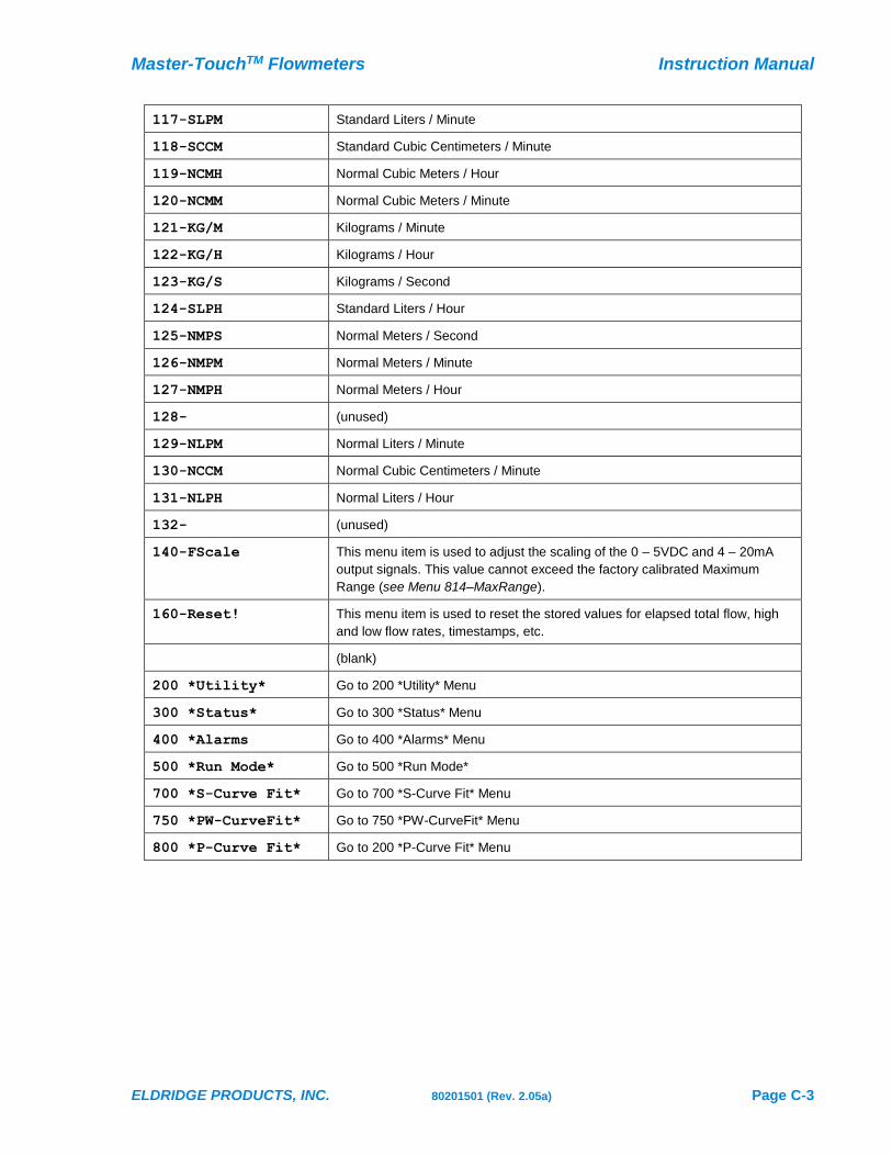
117-SLPM Standard Liters / Minute
118-SCCM Standard Cubic Centimeters / Minute
119-NCMH Normal Cubic Meters / Hour
120-NCMM Normal Cubic Meters / Minute
121-KG/M Kilograms / Minute
122-KG/H Kilograms / Hour
123-KG/S Kilograms / Second
124-SLPH Standard Liters / Hour
125-NMPS Normal Meters / Second
126-NMPM Normal Meters / Minute
127-NMPH Normal Meters / Hour
128- (unused)
129-NLPM Normal Liters / Minute
130-NCCM Normal Cubic Centimeters / Minute
131-NLPH Normal Liters / Hour
132- (unused)
140-FScale This menu item is used to adjust the scaling of the 0 – 5VDC and 4 – 20mA
output signals. This value cannot exceed the factory calibrated Maximum
Range (see Menu 814–MaxRange).
160-Reset! This menu item is used to reset the stored values for elapsed total flow, high
and low flow rates, timestamps, etc.
(blank)
200 *Utility* Go to 200 *Utility* Menu
300 *Status* Go to 300 *Status* Menu
400 *Alarms Go to 400 *Alarms* Menu
500 *Run Mode* Go to 500 *Run Mode*
700 *S-Curve Fit* Go to 700 *S-Curve Fit* Menu
750 *PW-CurveFit* Go to 750 *PW-CurveFit* Menu
800 *P-Curve Fit* Go to 200 *P-Curve Fit* Menu

Instruction Manual Master-TouchTM Flowmeters
Page C-4 80201501 (Rev. 2.05a) ELDRIDGE PRODUCTS, INC.
200 *Utility* Menu
The 200 *Utility* Menu of the Master-Touch™ flowmeter includes a series of submenu items which
allow you to easily change a wide variety of microprocessor parameters, such as the display update
rate, the internal date and time, the analog-to-digital (ADC) and digital-to-analog (DAC) signal
conversion filters, etc.
Although most settings are accessible by using the default user password of “9001”,
some of the parameters require a special password available only by contacting the
factory. This has been instituted to prevent the accidental change of critical settings.
112.3456 SCFM
9876.54321 SCF
RUN MODE
200 *Utility*
201-DAC Set
Actv Mtr#(1-4)
>1
Press MODE two times to advance to the 200 *Utility* menu. The display
shown at left will appear. The top line will show you that you are in the
correct menu. The bottom line presents the specific submenu items.
When you select a submenu which supports data entry a brief description
of the selected action will appear on the top line and the data entry field will
appear on the bottom line. In the example at left, submenu 213-Set Meter
has been selected and the flowmeter is displaying the active stored meter
range.
The following list shows the submenus and assumes that you will use the MAX key to advance
through the submenu items. You can use MIN key to go back to an item, or continue to use MAX
until the desired submenu appears again.
200 *Utility* Submenus
201-DAC Set This menu item requires the Diagnostic Password for access. Consult factory.
202-DAC Time This menu item is used to adjust the Digital-to-Analog converter (DAC)
response time interval. The value entered here is multiplied by 50ms to
establish the rate at which the DAC generates new output voltages.
Acceptable values are 1 – 63.
203-DAC Filter This menu item provides a smoothed DAC response to compensate for erratic
input signals caused by flow fluctuations. Higher values result in greater
dampening or smoothing; lower values result in a rapid response to changing
signals from the internal curve linearizer. Acceptable values are 1 – 127.
204-DAC Readout This menu item requires the Diagnostic Password for access. Consult factory.
205-ADC Filter This menu item provides a smoothed Analog-to-Digital Converter (ADC)
response to compensate for erratic input sensor signals caused by flow
fluctuations. Higher values result in greater dampening or smoothing; lower
values result in a rapid response to changing signals. Acceptable values are 1
– 255.
206-ADC Readout This menu item requires the Diagnostic Password for access. Consult factory.

Master-TouchTM Flowmeters Instruction Manual
ELDRIDGE PRODUCTS, INC. 80201501 (Rev. 2.05a) Page C-5
207-Disp Rate This menu item adjusts the rate at which the rate and totalizer readouts are
updated. It is often used to reduce the effect of a rapidly fluctuating flow rate
on the LCD display. Any value less than 8 (ms) should be avoided because it
will cause updates to the flow rate which will override the correct presentation
of the total elapsed flow on the LCD display.
This menu item only affects the totalizer and flow rate update period, not their
accuracy, and does not affect the 0–5VDC or 4–20mA output signals.
208-Disp Set This menu item sets the LCD panel contrast value. A value of 128 should
display digits at room temperature. Use the SHIFT + MAX / MIN keys during
Run Mode to fine tune this setting if necessary.
209-Curve Fit This menu item selects the curve fit mode used by the microprocessor to
generate the flow readings and output signals. The menu values are:
0 = NO = NO curve adjustment
1 = PO = Primary (factory) curve fit adjustment
2 = PS = Primary & Secondary curve fit adjustments
3 = PW = Primary & Pointwise curve fit adjustments
210-Modbus Addr This menu item sets the Modbus address for this flowmeter. A value of 0
disables Modbus protocol from the RS485 communications port and the data
sent out the RS485 port is the same as the RS232 port. A value of 1-127
enables the Modbus protocol on the RS485 port and this number is also the
flowmeter’s Modbus address. See Modbus manual for more details.
211-Tracking On This menu item restores the DAC and ADC tracking.
212-Track Hold This menu item suspends the DAC and ADC tracking.
This menu item requires the Diagnostic Password for access. Consult factory.
213-Set Meter This menu item is used to select the active meter range. All Master-Touch™
flowmeters are capable of storing configuration and parameter data for four
separate meter ranges. A specific meter range is selected by entering 1–4 in
this menu item. If a flowmeter has only one calibrated meter range, the factory
will program it as meter range #1 and meter ranges #2–4 will not contain any
valid variables.
The flowmeter can also be set up to allow external switching between stored
ranges by entering “0” at the prompt. However, EPICommunicator 2.0 software
must be used for this function as it affects the use of the keypad for access to
the menu system.
214-Set Date This menu item sets the time stamp functions to the current date for accurate
reporting. The menu supports both MM/DD/YY and DD.MM.YY time formats
where:
• MM = month (01–12)
• DD = day (01–31)
• YY = year (00–99)
Include a slash (/) as the delimiter between values for MM/DD/YY format, or a
period (.) as the delimiter between values for DD.MM.YY format. The date will
not be set if these formats are not followed exactly.

Instruction Manual Master-TouchTM Flowmeters
Page C-6 80201501 (Rev. 2.05a) ELDRIDGE PRODUCTS, INC.
215-Set Time This menu item sets the time stamp functions to the current time for accurate
reporting. The time prompt indicates HH:MM:SS where:
• HH = hour (00–23)
• MM = minutes (00–59)
• SS = seconds (00–59)
• . (period) = AM /PM or 24 hour clock
Include a colon (:) as the delimiter between values. The time will not be set if
this format is not followed exactly. Example:
01:24:56P = 1:24:56 PM
13:24:56 = 1:24:56 PM displayed in 24 hour clock format.
216-No Curve Fit This menu item suspends the factory P-Curve linearization.
This menu item requires the Diagnostic Password for access. Consult factory.
217-Curve Fit This menu item is the same as 209–Curve Fit
218-Reset Lock# This menu allows the four digit numeric password to be changed. The
flowmeter must be unlocked prior to accessing this menu item. All flowmeters
are shipped with an initial password of 9001 unless otherwise specified at the
time of purchase. The range of valid passwords is 9001–9999.
If you set your own password, save it in a secure place to prevent loss and
lockout from user variables.
219-UnLock This menu item is used to enter the pre-set four digit password that unlocks
the flowmeter’s settings. You can access any number of menu items while the
settings are unlocked. The settings are locked again when the flowmeter is
returned to Run Mode.
See Page D-1 for detailed instructions on this menu item.
220-Diagnostic P This menu item is the factory password for certain menu items which should
not ordinarily be accessed by users. These menu items include:
201–DAC Set 216–No Curve Fit
204–DAC Readout 801-812–CoeffTerm A-J (P-Curve coefficients)
206–ADC Readout 814–MaxRange
212–Tracking Off
221-SetCalDate This menu item can be set to act as a reminder for periodic recalibrations.
Enter the date of the next calibration reminder using the MM/DD/YY format, or
enter a zero-zero (00) for either the month or day to disable the reminder.
222-Fix Decimal This menu item controls the number of decimals shown in the flow rate
display. Enter a value from zero to six (0 to 6), or enter an “A” for the
automatic floating decimal.
This setting does not affect the total elapsed flow display nor does it affect the
accuracy of the flowmeter.
223-Set WD Timer This menu item allows the user to change the Watchdog (WD) timer “time-out”
period. The factory default setting is 3 which equals 3 minutes. This timer is
used to exit all menus after the time-out period. The MP will perform a reset
similar to the power down/power up reset. The minimum allowable value is 1;
the maximum allowable value is 120.
Master-TouchTM Flowmeters Instruction Manual
ELDRIDGE PRODUCTS, INC. 80201501 (Rev. 2.05a) Page C-7
224-ProtocolOnOff This menu item allows the flowmeter to use alternate communication protocols
such as HART and Modbus. The factory default is Protocol Off (0); when
HART, Modbus or other communication options are installed, the Protocol is
On (1). Consult factory for supported protocols.
When the Protocol is on (1) then EPIcommunicator’s RS232 communication is
disabled. You must use the flowmeter’s keypad or an EPICom II handheld device
to turn off the Protocol (0) which will enable the RS232 communications.
225-Set RS232 Baud This menu item adjusts the baud rate of the RS232 port.
0 = Factory Default (9600)
1 = 9600
2 = 14400
3 = 19200
4 = 28800
5 = 33400
6 = 56000
7 = 57600
8 = 115200
EPI’s LightWIRE IR communication modules currently require an RS232 baud
rate of 9600 and will not function correctly at other baud rates.
226-Set RS485 Baud This menu item adjusts the baud rate of the RS485 port.
0 = Factory Default (19200)
1 = 9600
2 = 14400
3 = 19200
4 = 28800
5 = 33400
6 = 56000
7 = 57600
8 = 115200
RS485 communications require an RS485-to-RS232 protocol converter for
connecting the flowmeter to a PC running EPICommunicator or similar software.
(blank)
100 *Meter* Go to 100 *Meter* Menu
300 *Status* Go to 300 *Status* Menu
400 *Alarms Go to 400 *Alarms* Menu
500 *Run Mode* Go to 500 *Run Mode*
700 *S-Curve Fit* Go to 700 *S-Curve Fit* Menu
750 *PW-CurveFit* Go to 750 *PW-CurveFit* Menu
800 *P-Curve Fit* Go to 800 *P-Curve Fit* Menu

Instruction Manual Master-TouchTM Flowmeters
Page C-8 80201501 (Rev. 2.05a) ELDRIDGE PRODUCTS, INC.
300 *Status* Menu
The 300 *Status* Menu of the Master-Touch™ flowmeter presents a series of menu items which
allow you to rapidly get important information from the flowmeter.
The following directions assume your flowmeter is in Run Mode and will use the MAX key to
advance through the menu items. You can use MIN key to go back to an item, or continue to use the
MAX key until the desired item appears again.
112.3456 SCFM
9876.54321 SCF
RUN MODE
300 *Status*
100 *Meter*
300 *Status*
1> PO 4353 SCFM
Press MODE three times to advance to the 300 *Status* menu. The display
shown at the right will appear briefly. The top line will always show you that
you are in the 300 *Status* menu. The second line presents the specific
menu items.
The display will change automatically to the first Status menu item. The first
character indicates which meter range is selected (1–4) or Tracking Off (!).
The second and third characters indicate the selected curve fit mode (NO,
PO, PS, PW). Each of the next four characters is the last digit of the
currently selected condition for Ev1, Ev2, Ev3, and Ev4 (see 400 *Alarm*
section for details). The final characters indicate the currently selected
engineering units for the rate and total information.
300 *Status*
HV123.4567 SCFM
This display presents the highest flow value since the last start up or reset.
300 *Status*
HT=01:23:45PM
This display presents the time stamp for the highest flow value.
300 *Status*
HD=08/09/98
This display presents the date stamp for the highest flow value.
300 *Status*
LV9.8765 SCFM
This display presents the lowest flow value since the last start up or reset.
300 *Status*
LT=05:43:21AM
This display presents the time stamp for the lowest flow value.
300 *Status*
LD=11/25/98
This display presents the date stamp for the lowest flow value.
300 *Status*
RT=10:23:45
This display presents the time stamp at which the totalizer was last reset to
zero.
300 *Status*
RD=06/23/98
This display presents the date stamp at which the totalizer was last reset to
zero.
Master-TouchTM Flowmeters Instruction Manual
ELDRIDGE PRODUCTS, INC. 80201501 (Rev. 2.05a) Page C-9
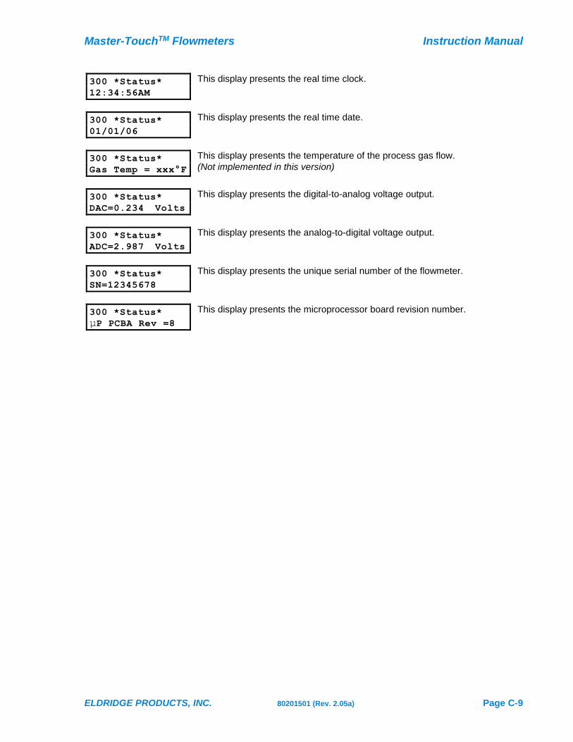
300 *Status*
12:34:56AM
This display presents the real time clock.
300 *Status*
01/01/06
This display presents the real time date.
300 *Status*
Gas Temp = xxx°F
This display presents the temperature of the process gas flow.
(Not implemented in this version)
300 *Status*
DAC=0.234 Volts
This display presents the digital-to-analog voltage output.
300 *Status*
ADC=2.987 Volts
This display presents the analog-to-digital voltage output.
300 *Status*
SN=12345678
This display presents the unique serial number of the flowmeter.
300 *Status*
µP PCBA Rev =8
This display presents the microprocessor board revision number.

Instruction Manual Master-TouchTM Flowmeters
Page C-10 80201501 (Rev. 2.05a) ELDRIDGE PRODUCTS, INC.
400 *Alarms* Menu
Alarm Relay Overview
Master-Touch™ flowmeters have two 1-amp SPDT relays that provide four relay Events (Ev1–Ev4):
• Relay 1 OFF (Ev1): the relay coil is de-energized with the Common and Normally Closed
connected
• Relay 1 ON (Ev2): the relay coil is energized with the Common and Normally Open
connected
• Relay 2 OFF (Ev3): the relay coil is de-energized with the Common and Normally Closed
connected
• Relay 2 ON (Ev4): the relay coil is energized with the Common and Normally Open
connected
These events can be used to activate other devices in response to a set of user-defined flow
conditions, or to provide pulsed outputs based on the current flow rate or the elapsed flow total.
There are eleven user-selectable conditions which will trigger an alarm relay response from a
Master-Touch™ flowmeter. These response conditions are:
• Trip High — an alarm relay is triggered by a flow rate that is higher than the preset value;
• Trip Low — an alarm relay is triggered by a flow rate that is lower than the preset value;
• Total — an alarm relay is triggered by an accumulated flow total that is higher than the preset
value;
• Timer — an alarm relay is triggered after a preset time delay value;
• Proportional Pulse Output — an alarm relay is triggered by a flow rate that is equal to a
preset proportion of the value in menu item 140–FScale;
• Pulse Output — an alarm relay is triggered after an preset value of accumulated flow total;
• MAX Key — an alarm relay is reset by momentarily pressing the MAX key on the LCD panel;
• MIN Key — an alarm relay is reset by momentarily pressing the MIN key on the LCD panel;
• ESD/EMI Rst — an alarm relay is triggered by electromagnetic impulse noise.
• Flow Hold 1 & 2 — the ADC input voltage is maintained at constant value, typically during gas
purge cycle
The alarm relays can also be reset externally by using the Mode 1 or Mode 2 and Ground
connections on Terminal Block One (TB1). Mode 1 is the same as using the MAX key; Mode 2 is the
same as using the MIN key. Momentarily grounding the appropriate Mode connection resets the
alarm relay. In addition, the alarm relays can be disabled so they do not trigger on any Event.
The Disabled function is also used to latch or hold the relay at its current condition. If no Event
programming has been requested at the time of purchase, Disabled is the default condition for the
alarm relays.
The flowmeter settings must be unlocked to change the alarm relay parameters (see
menu item 219–UnLock).
112.3456 SCFM
9876.54321 SCF
RUN MODE

Master-TouchTM Flowmeters Instruction Manual
ELDRIDGE PRODUCTS, INC. 80201501 (Rev. 2.05a) Page C-11
400 *Alarms*
401-Set Event
Event#(1-4)
>1
Press MODE four times to advance to the 400 *Alarms* menu. The display
shown at left will appear. The top line will show you that you are in the
correct menu. The bottom line presents the specific submenu items.
When you select a submenu which supports data entry a brief description
of the selected action will appear on the top line and the data entry field will
appear on the bottom line. In the example at left, submenu 401-Set Event
has been selected and the flowmeter is displaying the Alarm.
The following list shows the submenus and assumes that you will use the MAX key to advance
through the submenu items. You can use MIN key to go back to an item, or continue to use MAX
until the desired submenu appears again.
400 *Alarms* Submenus
401-Set Event This menu item selects the specific relay Event (Ev1–Ev4) to which a
response condition is assigned.
402-Disabled This menu item causes the current active Event to ignore all response
conditions.
403-Trip High This menu item sets the current active Event to respond to a flow rate that is
higher than the preset value.
404-Trip Low This menu item sets the current active Event to respond to a flow rate that is
lower than the preset value.
405-Max Button This menu item sets the current active Event to respond when the MAX key on
the LCD panel is pressed or when Mode 1 is grounded.
406-Min Button This menu item sets the current active Event to respond when the MIN key on
the LCD panel is pressed or when Mode 2 is grounded.
407-Timer This menu item sets current active Event to respond to a time duration, such as a
pulsed output. Enter the desired preset duration value in units of 50ms.
408-PropPOut This menu item sets the current active Event to respond to the current flow
rate. The pulses are based upon flow rate per minute, proportional to the value
in menu item 140–FScale. Using the keypad enter a value equal to the desired
number of pulses per minute at the Full Scale flow rate. Any value between 1
and 250 may be entered at the prompt (>).
The same value must be entered for both relay events (1&2 or 3&4). This will
give a 50/50 duty cycle.
409-Total This menu item sets the current active Event to respond to an elapsed total.
Enter the desired preset value in the current engineering units (whole numbers
only – no decimals).

Instruction Manual Master-TouchTM Flowmeters
Page C-12 80201501 (Rev. 2.05a) ELDRIDGE PRODUCTS, INC.
410-PulseOut This menu item sets the current active Event to respond to an elapsed total.
This function is used with remote data collection systems which count the
pulses to generate an elapsed flow total.
Enter a value to activate a relay for every X number of units on the totalized
flow, i.e., every 1 unit, 12 units, 50 units, etc. Any whole number between 1
and 2,000,000 may be entered at the prompt (>), but we recommend decimal
values (1, 10, 100, . . .).
A timer function must be associated with this menu item to release the relay
from the active state (see menu item 407–Timer). The timer must be set fast
enough to release the relay before the next preset total value is reached.
411-Trip Delay This menu item sets the response delay for the current active Event. Enter the
desired value in increments of 50ms (20 = 1 second). The acceptable values
are 1– 255.
412-ESD/EMI Rst This menu item detects LCD errors caused by power supply noise or other
electromagnetic interference. A value in increments of 50ms must be entered
to determine the duration of such interference before the relay responds. A
value of one (1) will cause a response to the shortest disturbance.
Consult factory for additional information and a diagram of required wiring of
input power to implement this function.
413-Flow Hold1 This menu item holds the ADC input value while Relay 1 Event 2 is on. When
the value is set to one (1), it will hold the ADC input at its current value. A
value of zero (0) will disable this feature.
414-Flow Hold2 This menu item holds the ADC input value while Relay 2 Event 4 is on. When
the value is set to one (1), it will hold the ADC input at its current value. A
value of zero (0) will disable this feature.
(blank)
100 *Meter* Go to 100 *Meter* Menu
200 *Utility* Go to 200 *Utility* Menu
300 *Status* Go to 300 *Status* Menu
500 *Run Mode* Go to 500 *Run Mode*
700 *S-Curve Fit* Go to 700 *S-Curve Fit* Menu
750 *PW-CurveFit* Go to 750 *PW-CurveFit* Menu
800 *P-Curve Fit* Go to 800 *P-Curve Fit* Menu
Alarm Programming
The alarm relays only operate while the flowmeter is the Run Mode. To select and program alarm
relay Events, use the 400 *Alarms* menu items. First, select the specific Event (Ev1–Ev4) in menu
item 401–Set Event. After selecting an Event, a condition is assigned (Timer, Max, PropPOut, etc.).
With the exception of setting the MAX or MIN keys for manual operation or to disable an Event,
each condition requires a numeric value to control the response. Depending upon the selected
condition, these values refer to 50 millisecond (ms) increments or to the currently selected
engineering units.
The flowmeter accepts settings for the Event until it returns to Run Mode, or until another Event is
selected by returning to menu item 401. Therefore, if a mistake is made while setting the parameters
Master-TouchTM Flowmeters Instruction Manual
ELDRIDGE PRODUCTS, INC. 80201501 (Rev. 2.05a) Page C-13
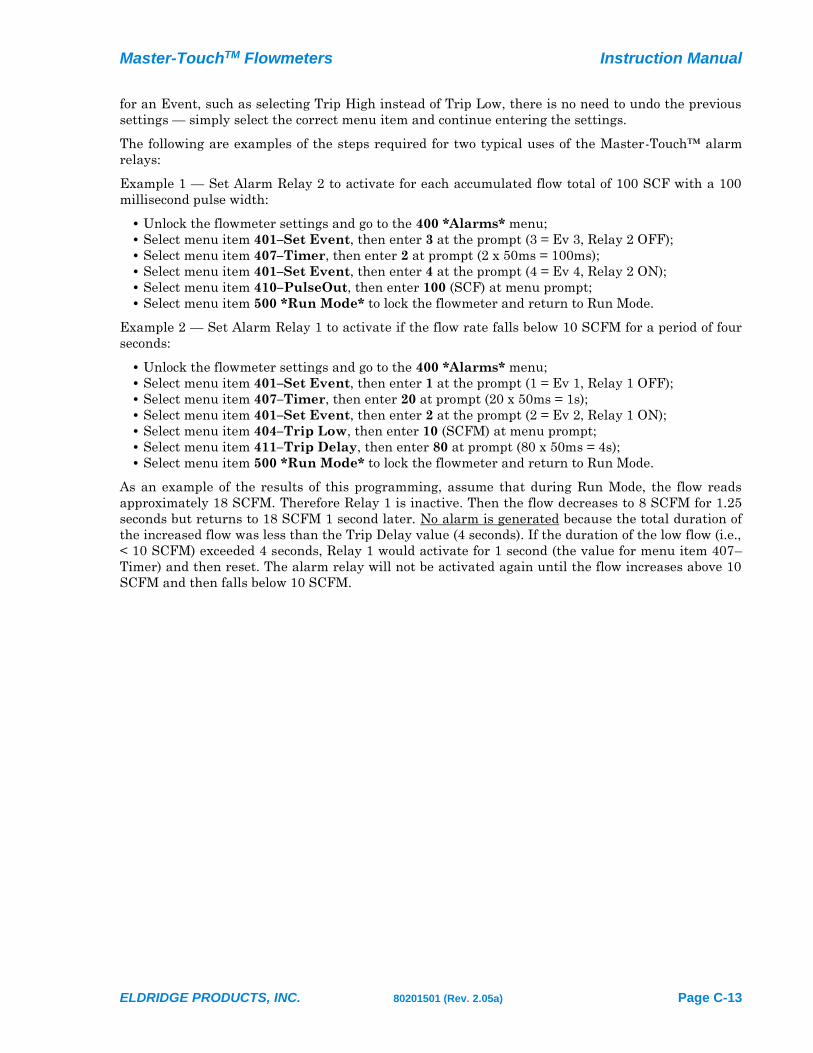
for an Event, such as selecting Trip High instead of Trip Low, there is no need to undo the previous
settings — simply select the correct menu item and continue entering the settings.
The following are examples of the steps required for two typical uses of the Master-Touch™ alarm
relays:
Example 1 — Set Alarm Relay 2 to activate for each accumulated flow total of 100 SCF with a 100
millisecond pulse width:
• Unlock the flowmeter settings and go to the 400 *Alarms* menu;
• Select menu item 401–Set Event, then enter 3 at the prompt (3 = Ev 3, Relay 2 OFF);
• Select menu item 407–Timer, then enter 2 at prompt (2 x 50ms = 100ms);
• Select menu item 401–Set Event, then enter 4 at the prompt (4 = Ev 4, Relay 2 ON);
• Select menu item 410–PulseOut, then enter 100 (SCF) at menu prompt;
• Select menu item 500 *Run Mode* to lock the flowmeter and return to Run Mode.
Example 2 — Set Alarm Relay 1 to activate if the flow rate falls below 10 SCFM for a period of four
seconds:
• Unlock the flowmeter settings and go to the 400 *Alarms* menu;
• Select menu item 401–Set Event, then enter 1 at the prompt (1 = Ev 1, Relay 1 OFF);
• Select menu item 407–Timer, then enter 20 at prompt (20 x 50ms = 1s);
• Select menu item 401–Set Event, then enter 2 at the prompt (2 = Ev 2, Relay 1 ON);
• Select menu item 404–Trip Low, then enter 10 (SCFM) at menu prompt;
• Select menu item 411–Trip Delay, then enter 80 at prompt (80 x 50ms = 4s);
• Select menu item 500 *Run Mode* to lock the flowmeter and return to Run Mode.
As an example of the results of this programming, assume that during Run Mode, the flow reads
approximately 18 SCFM. Therefore Relay 1 is inactive. Then the flow decreases to 8 SCFM for 1.25
seconds but returns to 18 SCFM 1 second later. No alarm is generated because the total duration of
the increased flow was less than the Trip Delay value (4 seconds). If the duration of the low flow (i.e.,
< 10 SCFM) exceeded 4 seconds, Relay 1 would activate for 1 second (the value for menu item 407–
Timer) and then reset. The alarm relay will not be activated again until the flow increases above 10
SCFM and then falls below 10 SCFM.

Instruction Manual Master-TouchTM Flowmeters
Page C-14 80201501 (Rev. 2.05a) ELDRIDGE PRODUCTS, INC.
450 *E-Log* Menu
The Master-Touch™ 5.0 software supports the E-Log™ data logger module. The E-Log™ functions
are accessible through the use of the 4-button keypad. Although data logging can be started and
stopped at any time, the microprocessor settings must be unlocked using Menu 219–UnLock to
make changes to the data logging options. The following list shows the submenus and their
functions. Some titles may be truncated on the display due to the limitations of the 16 characters per
line.
450 *E-Log*
451-Set StartDat
RUN MODE
451—Set StartDate This menu item is used to set the date to start collecting the data snapshots.
It uses the MM/DD/YY format.
452—Start Time(2) This menu item is used to set the time to start collecting the data snapshots.
It uses the HH:MM:SS format.
453—Set Stop Date This menu item is used to set the date to stop collecting the data snapshots.
It uses the MM/DD/YY format.
454—Stop Time(24) This menu item is used to set the time to stop collecting the data snapshots.
It uses the HH:MM:SS format.
455—Interval Time This menu item is used to set the time interval for each data snapshot.
It uses the HH:MM:SS format.
456—Option Date This menu item is used to include the current date in the data snapshot.
(0 = No; 1 = Yes)
457—Option Time This menu item is used to include the current time in the data snapshot.
(0 = No; 1 = Yes)
458—Option Flow This menu item is used to include the current flow rate in the data snapshot.
(0 = No; 1 = Yes)
459—Option Total This menu item is used to include the current elapsed total in the data
snapshot.
(0 = No; 1 = Yes)
460—Option High This menu item is used to include the highest flow rate in the data snapshot.
(0 = No; 1 = Yes)
461—Option Low This menu item is used to include the lowest flow rate in the data snapshot.
(0 = No; 1 = Yes)
462—Option Relay This menu item is used to include the status of Relay #1 in the data snapshot.
(0 = No; 1 = Yes)
463—Option Relay This menu item is used to include the status of Relay #2 in the data snapshot.
(0 = No; 1 = Yes)
464—Start Elog No This menu item is used to manually start collecting the data snapshots.
465—Stop Elog No This menu item is used to manually stop collecting the data snapshots.
Master-TouchTM Flowmeters Instruction Manual
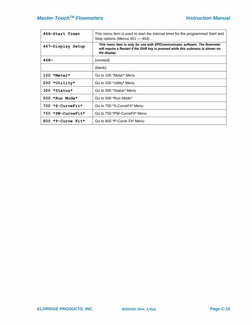
ELDRIDGE PRODUCTS, INC. 80201501 (Rev. 2.05a) Page C-15
466—Start Timer This menu item is used to start the internal timer for the programmed Start and
Stop options (Menus 451 — 454) .
467—Display Setup This menu item is only for use with EPICommunicator software. The flowmeter
will require a Restart if the Shift key is pressed while this submenu is shown on
the display.
468— (unused)
(blank)
100 *Meter* Go to 100 *Meter* Menu
200 *Utility* Go to 200 *Utility* Menu
300 *Status* Go to 300 *Status* Menu
500 *Run Mode* Go to 500 *Run Mode*
700 *S-CurveFit* Go to 700 *S-CurveFit* Menu
750 *PW-CurveFit* Go to 750 *PW-CurveFit* Menu
800 *P-Curve Fit* Go to 800 *P-Curve Fit* Menu

Instruction Manual Master-TouchTM Flowmeters
Page C-16 80201501 (Rev. 2.05a) ELDRIDGE PRODUCTS, INC.
700 *S-Curve Fit* Menu
The Master-Touch™ 5.0 software supports Secondary Curve (S-Curve) coefficients to modify the
factory calibration. The S-Curve coefficients are based on a difference between the EPI flowmeter's
readings and readings from another, or secondary, flow rate reference such as a pitot tube or other
flow measurement device (See Page-G2 for instructions)
The flowmeter settings must be unlocked to change the S-Curve coefficients (see menu
item 219–UnLock).
112.3456 SCFM
9876.54321 SCF
RUN MODE
700 *S-Curve Fit
701-CoeffTerm A
Term A Coeff
>0.000000e+00
Press MODE six times to advance to the 700 *S-Curve Fit* menu. The
display shown at left will appear. The top line will show you that you are in
the correct menu. The bottom line presents the specific submenu items.
When you select a submenu which supports data entry a brief description
of the selected action will appear on the top line and the data entry field will
appear on the bottom line. In the example at left, submenu 701-
CoeffTermA has been selected and the flowmeter is displaying the current
coefficient value.
The following list shows the submenus and assumes that you will use the MAX key to advance
through the submenu items. You can use MIN key to go back to an item, or continue to use MAX
until the desired submenu appears again.
700 *S-Curve Fit* Submenus
701-CoeffTermA See Secondary Coefficient instructions.
through
710-CoeffTermJ See Secondary Coefficient instructions
(blank)
100 *Meter* Go to 100 *Meter* Menu
200 *Utility* Go to 200 *Utility* Menu
300 *Status* Go to 300 *Status* Menu
400 *Alarms Go to 400 *Alarms* Menu
500 *Run Mode* Go to 500 *Run Mode*
750 *PW-CurveFit* Go to 750 *PW-CurveFit* Menu
800 *P-Curve Fit* Go to 800 *P-Curve Fit* Menu
Master-TouchTM Flowmeters Instruction Manual
ELDRIDGE PRODUCTS, INC. 80201501 (Rev. 2.05a) Page C-17
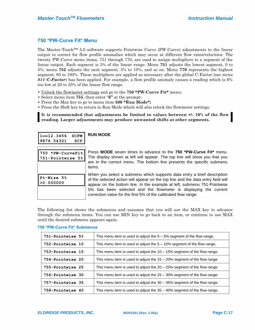
750 *PW-Curve Fit* Menu
The Master-Touch™ 5.0 software supports Pointwise Curve (PW-Curve) adjustments to the linear
output to correct for flow profile anomalies which may occur at different flow rates/velocities. The
twenty PW-Curve menu items, 751 through 770, are used to assign multipliers to a segment of the
linear output. Each segment is 5% of the linear range. Menu 751 adjusts the lowest segment, 0 to
5%; menu 752 adjusts the next segment, 5% to 10%, and so on. Menu 770 represents the highest
segment, 95 to 100%. These multipliers are applied as necessary after the global C-Factor (see menu
811–C-Factor) has been applied. For example, a flow profile anomaly causes a reading which is 6%
too low at 20 to 25% of the linear flow range.
• Unlock the flowmeter settings and go to the 750 *PW-Curve Fit* menu;
• Select menu item 755, then enter “6” at the prompt;
• Press the Max key to go to menu item 500 *Run Mode*;
• Press the Shift key to return to Run Mode which will also relock the flowmeter settings.
It is recommended that adjustments be limited to values between +/- 10% of the flow
reading. Larger adjustments may produce unwanted shifts at other segments.
112.3456 SCFM
9876.54321 SCF
RUN MODE
750 *PW-CurveFit
751-Pointwise 5%
Pt-Wise 5%
>0.000000
Press MODE seven times to advance to the 750 *PW-Curve Fit* menu.
The display shown at left will appear. The top line will show you that you
are in the correct menu. The bottom line presents the specific submenu
items.
When you select a submenu which supports data entry a brief description
of the selected action will appear on the top line and the data entry field will
appear on the bottom line. In the example at left, submenu 751-Pointwise
5% has been selected and the flowmeter is displaying the current
correction value for the first 5% of the calibrated flow range.
The following list shows the submenus and assumes that you will use the MAX key to advance
through the submenu items. You can use MIN key to go back to an item, or continue to use MAX
until the desired submenu appears again.
750 *PW-Curve Fit* Submenus
751-Pointwise 5% This menu item is used to adjust the 0 – 5% segment of the flow range.
752-Pointwise 10 This menu item is used to adjust the 5 – 10% segment of the flow range.
753-Pointwise 15 This menu item is used to adjust the 10 – 15% segment of the flow range.
754-Pointwise 20 This menu item is used to adjust the 15 – 20% segment of the flow range.
755-Pointwise 25 This menu item is used to adjust the 20 – 25% segment of the flow range.
756-Pointwise 30 This menu item is used to adjust the 25 – 30% segment of the flow range.
757-Pointwise 35 This menu item is used to adjust the 30 – 35% segment of the flow range.
758-Pointwise 40 This menu item is used to adjust the 35 – 40% segment of the flow range.

Instruction Manual Master-TouchTM Flowmeters
Page C-18 80201501 (Rev. 2.05a) ELDRIDGE PRODUCTS, INC.
759-Pointwise 45 This menu item is used to adjust the 40 – 45% segment of the flow range.
760-Pointwise 50 This menu item is used to adjust the 45 – 50% segment of the flow range.
761-Pointwise 55 This menu item is used to adjust the 50 – 55% segment of the flow range.
762-Pointwise 60 This menu item is used to adjust the 55 – 60% segment of the flow range.
763-Pointwise 65 This menu item is used to adjust the 60 – 65% segment of the flow range.
764-Pointwise 70 This menu item is used to adjust the 65 – 70% segment of the flow range.
765-Pointwise 75 This menu item is used to adjust the 70 – 75% segment of the flow range.
766-Pointwise 80 This menu item is used to adjust the 75 – 80% segment of the flow range.
767-Pointwise 85 This menu item is used to adjust the 80 – 85% segment of the flow range.
768-Pointwise 90 This menu item is used to adjust the 85 – 90% segment of the flow range.
769-Pointwise 95 This menu item is used to adjust the 90 – 95% segment of the flow range.
770-Pointwise 100 This menu item is used to adjust the 95 – 100% segment of the flow range.
780-All PW = 0% This menu item is used to reset all segments to the factory default of zero (0).
(blank)
100 *Meter* Go to 100 *Meter* Menu
200 *Utility* Go to 200 *Utility* Menu
300 *Status* Go to 300 *Status* Menu
400 *Alarms Go to 400 *Alarms* Menu
500 *Run Mode* Go to 500 *Run Mode*
700 *S-CurveFit* Go to 700 *S-CurveFit* Menu
800 *P-Curve Fit* Go to 800 *P-Curve Fit* Menu
Master-TouchTM Flowmeters Instruction Manual
ELDRIDGE PRODUCTS, INC. 80201501 (Rev. 2.05a) Page C-19
800 *P-Curve Fit* Menu
The Master-Touch™ 5.0 software stores the Primary Curve (P-Curve) coefficients which are
generated by the factory NIST calibration, as well as the global C-Factor, process line cross-sectional
area, etc.
Although most settings are accessible by using the default user password of “9001”,
some of the parameters require a special password available only by contacting the
factory. This has been instituted to prevent the accidental change of critical settings.
The P-Curve coefficients and MaxRange values should never be changed without
direct factory instructions.
112.3456 SCFM
9876.54321 SCF
RUN MODE
800 *P-Curve Fit
801-CoeffTerm A
Term A Coeff
>0.000000e+00
Press MODE eight times to advance to the 800 *P-Curve Fit* menu. The
display shown at left will appear. The top line will show you that you are in
the correct menu. The bottom line presents the specific submenu items.
When you select a submenu which supports data entry a brief description
of the selected action will appear on the top line and the data entry field will
appear on the bottom line. In the example at left, submenu 801-
CoeffTermA has been selected and the flowmeter is displaying the current
coefficient value.
The following list shows the submenus and assumes that you will use the MAX key to advance
through the submenu items. You can use MIN key to go back to an item, or continue to use MAX
until the desired submenu appears again.
800 *P-Curve Fit* Submenus
801-CoeffTermA Factory Calibration Coefficient.
Requires Diagnostic Password for access. Consult factory.
through
810-CoeffTermJ Factory Calibration Coefficient.
Requires Diagnostic Password for access. Consult factory.
811-C Factor This value is a multiplier used to adjust the P-Curve linearization. It is normally
set to 1.0, but may be adjusted based the Installation Guidelines, or to correct
for aberrations in sensor readings. The C Factor can also be used to change
standard conditions (STP) or to apply a density factor (vapor density) when
changing the engineering units from volumetric units (SCFM, NCMH, etc.) to
gravimetric units (Lbs/Hr, Kg/Hr, etc.) in flowmeters calibrated for gases other
than air.
812-Zero Offset This voltage value is subtracted from the sensor curve linearizer to correct for
minor sensor voltage errors. This ensures that zero flow is attained even
though some bias voltage may exit which would otherwise prevent an absolute
zero reading (see also menu item 815–Auto Zero).

Instruction Manual Master-TouchTM Flowmeters
Page C-20 80201501 (Rev. 2.05a) ELDRIDGE PRODUCTS, INC.
813-SetXSect This value is the cross-sectional area of the flow section or process line. The
units of measure are determined by the engineering units selected (see menu
items 101–132). For example, if the current engineering units are SCFM, then
the menu item 813 value must represent square feet (F2). A value of one (1)
may be used if the current engineering units represent velocity (SFPM, NMPS,
etc.) or if the flowmeter in an “inline” style with its own flow section.
814-MaxRange This is the maximum value of the factory NIST calibration. The units of
measure are determined by the engineering units selected (see menu items
101–132) and the value will change in response to changes to the engineering
units.
Requires Diagnostic Password for access. Consult factory.
815-Auto Zero This menu item automatically establishes a new Zero Offset (see menu item
812–Zero Offset). Entering a one (1) at the prompt changes the zero offset to
the 0–5VDC output voltage of the flowmeter when the selection is made. This
is particularly valuable for No Flow zeroing adjustments. Entering a zero (0) at
the prompt leaves the existing zero offset value unchanged.
816-FlowCutoff This menu item is used to set a percentage of the Maximum Range value
(menu item 814–MaxRange) as the minimum readable flow rate. Actual flow
rates below this minimum value will be treated as No Flow. The display will
show “Low” instead of the real-time flow rate, no additional elapsed flow will be
recorded, the 0–5VDC signal will drop to 0VDC, and the 4–20mA signal will
drop to 4mA. For example, if the Maximum Range is 1000 SCFM, a value of
10 (10%) will cause the flowmeter to ignore flow rates below 100 SCFM or
less. When the actual flow rate increases above this value, all of the
flowmeter’s functions will resume.
(blank)
100 *Meter* Go to 100 *Meter* Menu
200 *Utility* Go to 200 *Utility* Menu
300 *Status* Go to 300 *Status* Menu
400 *Alarms Go to 400 *Alarms* Menu
500 *Run Mode* Go to 500 *Run Mode*
700 *S-CurveFit* Go to 700 *S-CurveFit* Menu
750 *PW-Curve Fit* Go to 750 *PW-Curve Fit* Menu
ELDRIDGE PRODUCTS, INC. 80201501 (Rev. 2.05a) Page D-1
Section D Instructions for Specific Actions
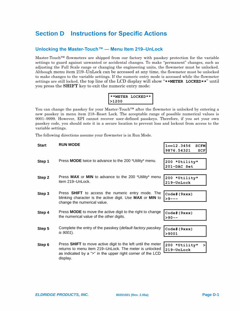
Unlocking the Master-Touch™ — Menu Item 219–UnLock
Master-Touch™ flowmeters are shipped from our factory with passkey protection for the variable
settings to guard against unwanted or accidental changes. To make “permanent” changes, such as
adjusting the Full Scale range or changing the engineering units, the flowmeter must be unlocked.
Although menu item 219–UnLock can be accessed at any time, the flowmeter must be unlocked
to make changes to the variable settings. If the numeric entry mode is accessed while the flowmeter
settings are still locked, the top line of the LCD display will show “**METER LOCKED**” until you press the SHIFT key to exit the numeric entry mode:
**METER LOCKED**
>1200
You can change the passkey for your Master-Touch™ after the flowmeter is unlocked by entering a
new passkey in menu item 218–Reset Lock. The acceptable range of possible numerical values is
9001–9999. However, EPI cannot recover user-defined passkeys. Therefore, if you set your own
passkey code, you should note it in a secure location to prevent loss and lockout from access to the
variable settings.
The following directions assume your flowmeter is in Run Mode.
Start RUN MODE 112.3456 SCFM
9876.54321 SCF
Step 1 Press MODE twice to advance to the 200 *Utility* menu. 200 *Utility*
201–DAC Set
Step 2 Press MAX or MIN to advance to the 200 *Utility* menu
item 219–UnLock. 200 *Utility*
219–UnLock
Step 3 Press SHIFT to access the numeric entry mode. The
blinking character is the active digit. Use MAX or MIN to
change the numerical value.
Code#(9xxx)
>9–––
Step 4 Press MODE to move the active digit to the right to change
the numerical value of the other digits. Code#(9xxx)
>90––
Step 5 Complete the entry of the passkey (default factory passkey
is 9001). Code#(9xxx)
>9001
Step 6 Press SHIFT to move active digit to the left until the meter
returns to menu item 219–UnLock. The meter is unlocked
as indicated by a “>“ in the upper right corner of the LCD
display.
200 *Utility* >
219–UnLock
Instruction Manual Master-TouchTM Flowmeters
Page D-2 80201501 (Rev. 2.05a) ELDRIDGE PRODUCTS, INC.
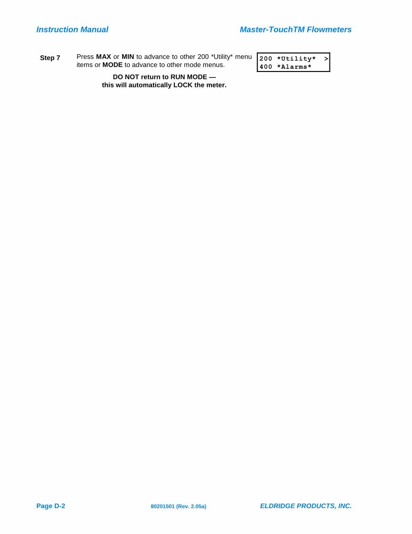
Step 7 Press MAX or MIN to advance to other 200 *Utility* menu
items or MODE to advance to other mode menus.
DO NOT return to RUN MODE —
this will automatically LOCK the meter.
200 *Utility* >
400 *Alarms*

Master-TouchTM Flowmeters Instruction Manual
ELDRIDGE PRODUCTS, INC. 80201501 (Rev. 2.05a) Page D-3
Selecting the Engineering Units — Menu Items 101–132
Master-Touch™ flowmeters allow you to choose from a variety of engineering units to measure the
flow rate and elapsed total. The menu items 101 through 132 have been designated for this purpose,
though not all items are currently assigned. Please note that changing the engineering units from
SCFM, NCMH, etc. to Lb/H, Kg/H, etc. requires factory assistance for all gases other than air.
The following directions assume that you have just unlocked the flowmeter. However, the 100
*Meter* menu can be accessed directly from the other mode menus by pressing MODE until it is
shown on the LCD display and then pressing SHIFT.
Start Menu item 219–UnLock 200 *Utility* >
219–UnLock
Step 1 Press MAX twice to advance to the 200 *Utility* menu item
100 *Meter*. 200 *Utility* >
100 *Meter*
Step 2 Press SHIFT to advance to the 100 *Utility* menu. 100 *Meter* >
101–SCFM
Step 3 Press MAX or MIN to advance to the 100 *Utility* menu
item of the engineering unit you desire. Press SHIFT to
select the engineering unit.
100 *Meter* >
119–NCMH
NOTE DO NOT select any blank menu item — this will cause
a failure and the flowmeter will need to be powered
down and powered up again.
100 *Meter* >
107–
Step 4a If further adjustments are required, press MAX or MIN to
advance to other 100 *Meter* menu items or MODE to
advance to other main menus.
DO NOT return to RUN MODE —
this will automatically LOCK the meter.
100 *Meter* >
800 *Factory*
Step 4b If no further adjustments are required, press MAX to
advance to the 500 *Run Mode* menu item, then press
SHIFT to lock the flowmeter and to return to Run Mode.
100 *Meter* >
500 *Run Mode*

Instruction Manual Master-TouchTM Flowmeters
Page D-4 80201501 (Rev. 2.05a) ELDRIDGE PRODUCTS, INC.
Changing the Full Scale range — Menu Item 140–FScale
Master-Touch™ flowmeters allow you to set the Full Scale range to any value less than or equal to
the calibrated MaxRange value. For example, if the factory calibration set your Full Scale to 5,000
SCFM and the MaxRange at 6,000 SCFM, the Full Scale can be set as high as 6,000 SCFM or as low
as practical for your application. Adjustments to this setting scale the 0–5VDC and 4–20mA output
signals to the new Full Scale range.
The following directions assume that you have just unlocked the flowmeter. However, the 100
*Meter* menu can be accessed directly from the other mode menus by pressing MODE until it is
shown on the LCD display and then pressing SHIFT.
Start Menu item 219–UnLock 200 *Utility* >
219–UnLock
Step 1 Press MAX twice to advance to the 200 *Utility* menu item
100 *Meter*. 200 *Utility* >
100 *Meter*
Step 2 Press SHIFT to advance to the 100 *Utility* menu. 100 *Meter* >
101–SCFM
Step 3 Press MAX or MIN to advance to the 100 *Utility* menu
item 140–FScale. 100 *Meter* >
140–FScale
Step 4 Press SHIFT to access the numeric entry mode. Set Full Scale >
>5000
Step 5 The blinking character is the active digit. Use MAX or MIN
to change the numerical value. Use MODE to move the
active digit to the right and complete the entry of the new
Full Scale value.
Set Full Scale >
>4500
Step 6 Press SHIFT to move active digit to the left until the meter
returns to menu item 140–FScale. The Full Scale setting is
now changed.
100 *Meter* >
140–FScale
Step 7a If further adjustments are required, press MAX or MIN to
advance to other 100 *Meter* menu items or MODE to
advance to other main menus.
DO NOT return to RUN MODE —
this will automatically LOCK the meter.
100 *Meter* >
800 *Factory*
Step 7b If no further adjustments are required, press MAX four
times to advance to the 500 *Run Mode* menu item, then
press SHIFT to lock the flowmeter and to return to Run
Mode.
100 *Meter* >
500 *Run Mode*

Master-TouchTM Flowmeters Instruction Manual
ELDRIDGE PRODUCTS, INC. 80201501 (Rev. 2.05a) Page D-5
Resetting the Flow Rate and Flow Total — Menu Item 160–Reset!
Master-Touch™ flowmeters allow you to reset the flow rate and elapsed flow totals to zero at any
time. The flowmeter must be unlocked for reset these values.
The following directions assume that you are in Run Mode. However, the 100 *Meter* menu can be
accessed directly from the other mode menus by pressing MODE until it is shown on the LCD
display and then pressing SHIFT.
Start Menu item 219–UnLock 200 *Utility* >
219–UnLock
Step 1 Press MAX four times to advance to the 200 *Utility* menu
item 100 *Meter*. 200 *Utility* >
100 *Meter*
Step 2 Press SHIFT to advance to the 100 *Utility* menu. 100 *Meter* >
101–SCFM
Step 3 Press MAX or MIN to advance to the 100 *Utility* menu
item 160–Reset!. Press SHIFT to reset the values to zero.
The flowmeter will automatically return to Run Mode within
1–2 seconds.
100 *Meter*
160–Reset!
Instruction Manual Master-TouchTM Flowmeters
Page D-6 80201501 (Rev. 2.05a) ELDRIDGE PRODUCTS, INC.
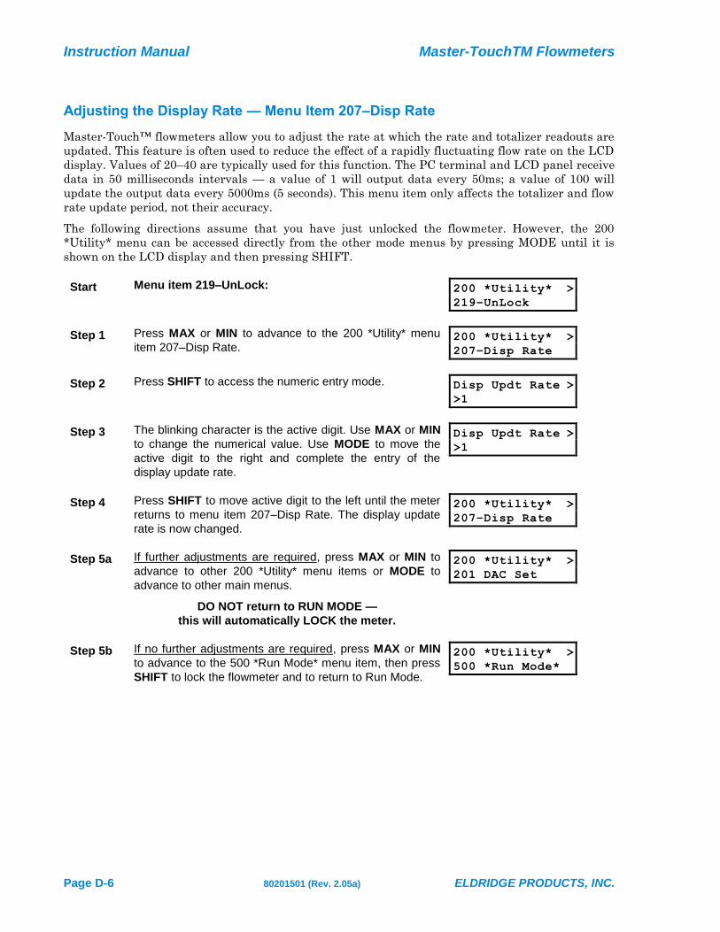
Adjusting the Display Rate — Menu Item 207–Disp Rate
Master-Touch™ flowmeters allow you to adjust the rate at which the rate and totalizer readouts are
updated. This feature is often used to reduce the effect of a rapidly fluctuating flow rate on the LCD
display. Values of 20–40 are typically used for this function. The PC terminal and LCD panel receive
data in 50 milliseconds intervals — a value of 1 will output data every 50ms; a value of 100 will
update the output data every 5000ms (5 seconds). This menu item only affects the totalizer and flow
rate update period, not their accuracy.
The following directions assume that you have just unlocked the flowmeter. However, the 200
*Utility* menu can be accessed directly from the other mode menus by pressing MODE until it is
shown on the LCD display and then pressing SHIFT.
Start Menu item 219–UnLock: 200 *Utility* >
219–UnLock
Step 1 Press MAX or MIN to advance to the 200 *Utility* menu
item 207–Disp Rate. 200 *Utility* >
207–Disp Rate
Step 2 Press SHIFT to access the numeric entry mode. Disp Updt Rate >
>1
Step 3 The blinking character is the active digit. Use MAX or MIN
to change the numerical value. Use MODE to move the
active digit to the right and complete the entry of the
display update rate.
Disp Updt Rate >
>1
Step 4 Press SHIFT to move active digit to the left until the meter
returns to menu item 207–Disp Rate. The display update
rate is now changed.
200 *Utility* >
207–Disp Rate
Step 5a If further adjustments are required, press MAX or MIN to
advance to other 200 *Utility* menu items or MODE to
advance to other main menus.
DO NOT return to RUN MODE —
this will automatically LOCK the meter.
200 *Utility* >
201 DAC Set
Step 5b If no further adjustments are required, press MAX or MIN
to advance to the 500 *Run Mode* menu item, then press
SHIFT to lock the flowmeter and to return to Run Mode.
200 *Utility* >
500 *Run Mode*

Master-TouchTM Flowmeters Instruction Manual
ELDRIDGE PRODUCTS, INC. 80201501 (Rev. 2.05a) Page D-7
Adjusting the LCD Display Contrast — Menu Item 208–Disp Set
Master-Touch™ flowmeters allow you to adjust the LCD contrast value in menu item 208–Disp Set.
The factory default value is 128. This setting should display all digits clearly at room temperature.
Colder temperatures may darken the display; warmer temperatures may lighten it. Values lower
than 128 lighten the display; values greater than 128 darken the display (the contrast can also be
adjusted in Run Mode by pressing SHIFT+MAX to darken the display or SHIFT+MIN to lighten the
display).
The following directions assume that you have just unlocked the flowmeter. However, the 200
*Utility* menu can be accessed directly from the other mode menus by pressing MODE until it is
shown on the LCD display and then pressing SHIFT.
Start Menu item 219–UnLock: 200 *Utility* >
219–UnLock
Step 1 Press MAX or MIN to advance to the 200 *Utility* menu
item 208–Disp Set. 200 *Utility* >
208–Disp Set
Step 2 Press SHIFT to access the numeric entry mode. Contrast(1–200)>
>128
Step 3 The blinking character is the active digit. Use MAX or MIN
to change the numerical value. Use MODE to move the
active digit to the right and complete the entry of the
display contrast.
Contrast(1–200)>
>145
Step 4 Press SHIFT to move active digit to the left until the meter
returns to menu item 208–Disp Set. The display contrast is
now changed.
200 *Utility* >
208–Disp Set
Step 5a If further adjustments are required, press MAX or MIN to
advance to other 200 *Utility* menu items or MODE to
advance to other main menus.
DO NOT return to RUN MODE —
this will automatically LOCK the meter.
200 *Utility* >
201 DAC Set
Step 5b If no further adjustments are required, press MAX or MIN
to advance to the 500 *Run Mode* menu item, then press
SHIFT to lock the flowmeter and to return to Run Mode.
200 *Utility* >
500 *Run Mode*
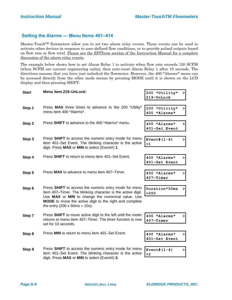
Instruction Manual Master-TouchTM Flowmeters
Page D-8 80201501 (Rev. 2.05a) ELDRIDGE PRODUCTS, INC.
Setting the Alarms — Menu Items 401–414
Master-Touch™ flowmeters allow you to set two alarm relay events. These events can be used to
activate other devices in response to user-defined flow conditions, or to provide pulsed outputs based
on flow rate or flow total. Please see the EPITerm section of the Instruction Manual for a complete
discussion of the alarm relay events.
The example below shows how to set Alarm Relay 1 to activate when flow rate exceeds 120 SCFM
(when SCFM are current engineering units), then auto-reset Alarm Relay 1 after 10 seconds. The
directions assume that you have just unlocked the flowmeter. However, the 400 *Alarms* menu can
be accessed directly from the other mode menus by pressing MODE until it is shown on the LCD
display and then pressing SHIFT.
Start Menu item 219–UnLock: 200 *Utility* >
219–UnLock
Step 1 Press MAX three times to advance to the 200 *Utility*
menu item 400 *Alarms*. 200 *Utility* >
400 *Alarms*
Step 2 Press SHIFT to advance to the 400 *Alarms* menu. 400 *Alarms* >
401–Set Event
Step 3 Press SHIFT to access the numeric entry mode for menu
item 401–Set Event. The blinking character is the active
digit. Press MAX or MIN to select (Event#) 1.
Event#(1-4) >
>1
Step 4 Press SHIFT to return to menu item 401–Set Event. 400 *Alarms* >
401–Set Event
Step 5 Press MAX to advance to menu item 407–Timer. 400 *Alarms* >
407–Timer
Step 6 Press SHIFT to access the numeric entry mode for menu
item 407–Timer. The blinking character is the active digit.
Use MAX or MIN to change the numerical value. Use
MODE to move the active digit to the right and complete
the entry (200 x 50ms = 10s).
Duration*50ms >
>200
Step 7 Press SHIFT to move active digit to the left until the meter
returns to menu item 407–Timer. The timer function is now
set for 10 seconds.
400 *Alarms* >
407–Timer
Step 8 Press MIN to return to menu item 401–Set Event. 400 *Alarms* >
401–Set Event
Step 9 Press SHIFT to access the numeric entry mode for menu
item 401–Set Event. The blinking character is the active
digit. Press MAX or MIN to select (Event#) 2.
Event#(1-4) >
>2

Master-TouchTM Flowmeters Instruction Manual
ELDRIDGE PRODUCTS, INC. 80201501 (Rev. 2.05a) Page D-9
Step 10 Press SHIFT to return to menu item 401–Set Event. 400 *Alarms* >
401–Set Event
Step 11 Press MAX to advance to menu item 403–Trip High. 400 *Alarms* >
403–Trip High
Step 12 Press SHIFT to access the numeric entry mode for menu
item 403–Trip High. The blinking character is the active
digit. Use MAX or MIN to change the numerical value. Use
MODE to move the active digit to the right and complete
the entry for 120 (this value correlates to the currently
selected engineering units).
High Value >
>120
Step 13 Press SHIFT to move active digit to the left until the meter
returns to menu item 403–Trip High. The high flow value is
now set.
400 *Alarms* >
403–Trip High
Step 14a If further adjustments are required, press MAX or MIN to
advance to other 400 *Alarms* menu items or MODE to
advance to other main menus.
DO NOT return to RUN MODE —
this will automatically LOCK the meter.
400 *Alarms* >
401–Set Event
Step 14b If no further adjustments are required, press MAX or MIN
to advance to the 500 *Run Mode* menu item, then press
SHIFT to lock the flowmeter and to return to Run Mode.
400 *Alarms* >
500 *Run Mode*

Instruction Manual Master-TouchTM Flowmeters
Page D-10 80201501 (Rev. 2.05a) ELDRIDGE PRODUCTS, INC.
Adjusting the C Factor — Menu Item 811–C Factor
Master-Touch™ flowmeters allow you to adjust the correction factor setting. The factory default for
this value is 1. By changing the value in this menu item, you can rescale the flowmeter’s curve
linearization to correct for aberrations in the sensor readings.
The following directions assume that you have just unlocked the flowmeter. However, the 800
*Meter* menu can be accessed directly from the other mode menus by pressing MODE until it is
shown on the LCD display and then pressing SHIFT.
Start Menu item 219–UnLock: 200 *Utility* >
219–UnLock
Step 1 Press MAX five times to advance to the 200 *Utility* menu
item 800 *Factory*. 200 *Utility* >
800 *Factory*
Step 2 Press SHIFT to advance to the 800 *Factory* menu. 800 *Factory* >
801–CoeffTermA
Step 3 Press MAX or MIN to advance to the 800 *Factory* menu
item 811–C Factor. 800 *Factory* >
811–C Factor
Step 4 Press SHIFT to access the numeric entry mode. Set Correction >
>1.000000e+00
Step 5 The blinking character is the active digit. Use MAX or MIN
to change the numerical value. Use MODE to move the
active digit to the right and complete the entry of the new
correction factor.
Set Correction >
>1.050000e+00
Step 6 Press SHIFT to move active digit to the left until the meter
returns to menu item 811–C Factor. The correction factor
is now changed.
800 *Factory* >
811–C Factor
Step 7a If further adjustments are required, press MAX or MIN to
advance to other 800 *Factory* menu items or MODE to
advance to other main menus.
DO NOT return to RUN MODE —
this will automatically LOCK the meter.
800 *Factory* >
801–CoeffTermA
Step 7b If no further adjustments are required, press MODE twice
to advance to the 600 *Turbo* menu. The flowmeter will
return to Run Mode and relock.
600 *Turbo* >
100 *Meter*
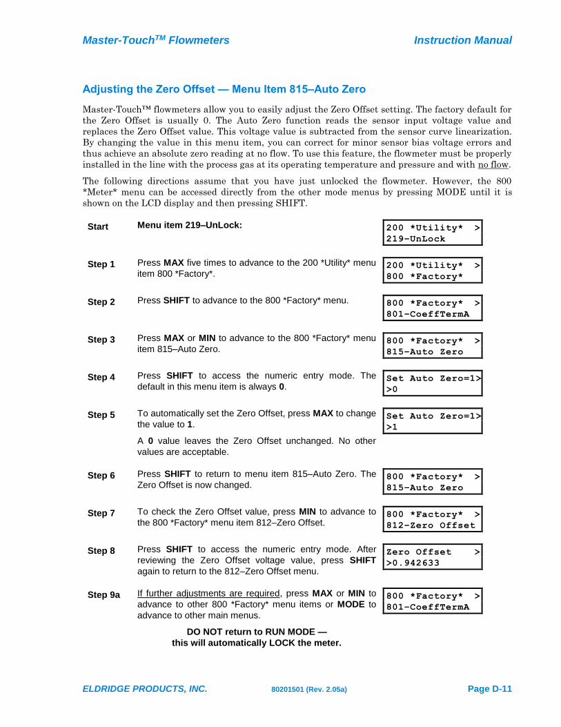
Master-TouchTM Flowmeters Instruction Manual
ELDRIDGE PRODUCTS, INC. 80201501 (Rev. 2.05a) Page D-11
Adjusting the Zero Offset — Menu Item 815–Auto Zero
Master-Touch™ flowmeters allow you to easily adjust the Zero Offset setting. The factory default for
the Zero Offset is usually 0. The Auto Zero function reads the sensor input voltage value and
replaces the Zero Offset value. This voltage value is subtracted from the sensor curve linearization.
By changing the value in this menu item, you can correct for minor sensor bias voltage errors and
thus achieve an absolute zero reading at no flow. To use this feature, the flowmeter must be properly
installed in the line with the process gas at its operating temperature and pressure and with no flow.
The following directions assume that you have just unlocked the flowmeter. However, the 800
*Meter* menu can be accessed directly from the other mode menus by pressing MODE until it is
shown on the LCD display and then pressing SHIFT.
Start Menu item 219–UnLock: 200 *Utility* >
219–UnLock
Step 1 Press MAX five times to advance to the 200 *Utility* menu
item 800 *Factory*. 200 *Utility* >
800 *Factory*
Step 2 Press SHIFT to advance to the 800 *Factory* menu. 800 *Factory* >
801–CoeffTermA
Step 3 Press MAX or MIN to advance to the 800 *Factory* menu
item 815–Auto Zero. 800 *Factory* >
815–Auto Zero
Step 4 Press SHIFT to access the numeric entry mode. The
default in this menu item is always 0. Set Auto Zero=1>
>0
Step 5 To automatically set the Zero Offset, press MAX to change
the value to 1.
A 0 value leaves the Zero Offset unchanged. No other
values are acceptable.
Set Auto Zero=1>
>1
Step 6 Press SHIFT to return to menu item 815–Auto Zero. The
Zero Offset is now changed. 800 *Factory* >
815–Auto Zero
Step 7 To check the Zero Offset value, press MIN to advance to
the 800 *Factory* menu item 812–Zero Offset. 800 *Factory* >
812–Zero Offset
Step 8 Press SHIFT to access the numeric entry mode. After
reviewing the Zero Offset voltage value, press SHIFT
again to return to the 812–Zero Offset menu.
Zero Offset >
>0.942633
Step 9a If further adjustments are required, press MAX or MIN to
advance to other 800 *Factory* menu items or MODE to
advance to other main menus.
DO NOT return to RUN MODE —
this will automatically LOCK the meter.
800 *Factory* >
801–CoeffTermA
Instruction Manual Master-TouchTM Flowmeters
Page D-12 80201501 (Rev. 2.05a) ELDRIDGE PRODUCTS, INC.
Step 9b If no further adjustments are required, press MODE twice
to advance to the 600 *Turbo* menu. The flowmeter will
return to Run Mode and relock.
600 *Turbo* >
100 *Meter*

Master-TouchTM Flowmeters Instruction Manual
ELDRIDGE PRODUCTS, INC. 80201501 (Rev. 2.05a) Page D-13
Setting the Low Flow Cutoff — Menu Item 816–FlowCutoff
Master-Touch™ flowmeters allow you to easily set a flow signal cutoff for a full scale flow range that
has a low end other than zero (0), i.e., 100–1000 SCFM. This function is controlled by Menu 816-
FlowCutoff. The value entered at this menu is the percentage of the Maximum Range that equals the
desired cutoff limit (see menu item 814–MaxRange). As an example, if the specified flow range is
150–1000 SCFM and the Maximum Range value is 1200 SCFM, then to set the low end limit of 150
SCFM the menu item 816 value must be 12.5 (%) because 1200 x 0.125 = 150. When the flow rate is
below this flow cutoff limit, the display reads “LOW” and the output signals will be 0VDC and 4mA.
When the flow rate is above the cutoff limit the flow rate will be displayed and the output signals
will resume at the correct level.
The following directions assume that you have just unlocked the flowmeter. However, the 800
*Meter* menu can be accessed directly from the other mode menus by pressing MODE until it is
shown on the LCD display and then pressing SHIFT.
Start Menu item 219–UnLock: 200 *Utility* >
219–UnLock
Step 1 Press MAX five times to advance to the 200 *Utility* menu
item 800 *Factory*. 200 *Utility* >
800 *Factory*
Step 2 Press SHIFT to advance to the 800 *Factory* menu. 800 *Factory* >
801–CoeffTermA
Step 3 Press MAX or MIN to advance to the 800 *Factory* menu
item 816–FlowCutoff. 800 *Factory* >
816–FlowCutoff
Step 4 Press SHIFT to access the numeric entry mode. The
default in this menu item is always 0. Set Low >
>0
Step 5 The blinking character is the active digit. Use MAX or MIN
to change the numerical value. Use MODE to move the
active digit to the right and complete the entry of the flow
signal cutoff percentage.
Set Low >
>12.5
Step 6 Press SHIFT to return to menu item 816–FlowCutoff. The
flow signal cutoff is now set. 800 *Factory* >
816–FlowCutoff
Step 7a If further adjustments are required, press MAX or MIN to
advance to other 800 *Factory* menu items or MODE to
advance to other main menus.
DO NOT return to RUN MODE —
this will automatically LOCK the meter.
800 *Factory* >
801–CoeffTermA
Step 7b If no further adjustments are required, press MODE twice
to advance to the 600 *Turbo* menu. The flowmeter will
return to Run Mode and relock.
600 *Turbo* >
100 *Meter*

ELDRIDGE PRODUCTS, INC. 80201501 (Rev. 2.05a) Page E-1
Section E Factory Calibration
The factory calibration of an Eldridge thermal gas mass flowmeter is a two step process. Our first
step is to perform a temperature calibration of each flow sensor. Once this calibration process has
been performed, it need not be done again. Secondly, we perform a flow calibration of every
flowmeter. Although all flow curves are similar, they are different enough to require individual
calibrations be run for each flowmeter to yield the best accuracy.
Flow calibration is a process of comparing or verifying the meter under test against a meter of better
accuracy used as a calibration standard. EPI flow calibrations are traceable to NIST through
traceability of the instrumentation and equipment used.
Calibration of the flowmeter consists of the following steps. Flowmeters are checked against a
calibration standard at many flow points and the data is graphed. From this graph the non-linearity
of the flowmeter is determined and aligned through our signal processor to yield a linear flow output
signal.
Although thermal gas mass flowmeters have good long term stability, EPI recommends a factory
calibration and certification be performed on an annual basis to conform to most quality assurance
programs. Where quality assurance programs do not require annual recertification, it shall be left at
the users’ discretion when to recertify.

ELDRIDGE PRODUCTS, INC. 80201501 (Rev. 2.05a) Page F-1
Section F General Specifications
Linear signal output 0–5 VDC & 4–20 mA
Relay Output Two 1-amp, user-selectable alarm functions
Signal Interface RS232 & RS485
Accuracy including linearity (Ref.: 21°C): ± (1% of Reading + (0.5% + .02%/°C of Full Scale))
Repeatability ± 0.2% of Full Scale
Sensor response time 1 second (time constant per step change)
Turn down ratio 100:1 (15 SCFM/FT2 minimum Reading)
Electronics internal temperature range 0° to 50°C (32° to 122°F) Standard
-40° to 60°C (-40° to 140°F) Optional temperature range
Gas temperature range 0–200°C (32–392°F) Consult factory for extended range.
Gas temperature effect 0.02% /°C
Gas pressure effect Negligible over 20% of absolute calibration pressure
Pressure rating maximum:
Transmitter power requirements 5 Watts or less
RAM Back-up Lithium Battery, 2.5–3.5v, >10 years
Wetted materials: 316SS, including sensor
Standard temperature & pressure (STP) 70° F & 29.92" Hg
(Air .075 lb/cubic foot)
NIST traceable calibration Standard
Specification Notice
Specifications contained herein are subject to change without notice, EPI cannot guarantee the
applicability or suitability of our products in all situations since it is impossible to anticipate or
control every condition under which our products and specifications may be used.
Service Work
In the event that service work is required or calibration and recertification is required, call the
factory and a return materials authorization (RMA) number will be issued for each job. All units sent
in for service work shall include a RMA, work instructions and be shipped prepaid. On receipt of
your flow instrumentation, we will inspect the equipment and give a price quotation for service work
to be performed, if not already given.
Storage
Equipment and instrumentation shall be stored in an environmentally controlled storage shelter or
warehouse when not in use. All openings shall be sealed off to prevent foreign materials from
entering the instrumentation.

Instruction Manual Master-TouchTM Flowmeters
Page F-2 80201501 (Rev. 2.05a) ELDRIDGE PRODUCTS, INC.
Limited Warranty
Eldridge Products, Inc. (EPI) warrants its products to be free from defects in materials and
workmanship for one year from the date of factory shipment. If there is a defect, the purchaser must
notify EPI of the defect within the warranty period. Upon receipt of the defective product, EPI will
either repair or replace the defective product at its sole option. EPI MAKES NO OTHER
WARRANTY, EXPRESS OR IMPLIED, AS TO THE PRODUCTS. EPI MAKES NO WARRANTY
THAT THE GOODS SOLD TO ANY PURCHASER ARE FIT FOR ANY PARTICULAR PURPOSE.
FURTHERMORE, EPI MAKES NO WARRANTY OF MERCHANTABILITY WITH RESPECT TO
ANY PRODUCTS SOLD TO ANY PURCHASERS. There are no other warranties that extend
beyond the description on any brochure or price quote.
Limited Acceptance
Acceptance of any offer is limited to its terms. Acceptances or confirmations that state additional or
differing terms from this price quote shall be operative as acceptances, but all additional or differing
terms shall be deemed material alterations within the meaning of Commercial Code Section
2207(2)(b), and notice of objection to them pursuant to Commercial Code Section 2207(2)(c) is hereby
given. The laws of the State of California govern this contract and venue is Monterey County. Risk of
loss passes F.O.B. EPI factory. Payment due in full in US Dollars within credit terms granted from
factory shipment. Additional fees shall include interest on unpaid balances that are outstanding for
more than granted credit terms, plus all collection costs and attorneys’ fees incurred in collecting any
outstanding balance. Any and all additional or differing terms do not become part of the contract
between EPI and any purchaser.
The terms of any offer are expressly limited to the terms detailed in any product brochure or price
quote. Any modification to any of the terms of this offer must be in writing and must be signed by an
officer of EPI.

ELDRIDGE PRODUCTS, INC. 80201501 (Rev. 2.05a) Page G-1
Section G Guidelines and Product Drawings
Calculating Secondary Coefficients
The Master-Touch™ 4.1 software supports Secondary Coefficients to modify the factory calibration.
The Secondary Coefficients are based on a difference between the EPI flowmeter's readings and
readings from another, or Secondary, flow rate reference such as a pitot tube or other flow
measurement device. The calculations require the EPI Secondary Coefficients Calculator
spreadsheet which is available by contacting our factory directly.
Please note the following before using the spreadsheet:
1) The specific engineering units are NOT important in this calculation.
2) Any adjustments to the EPI flowmeter’s “0” reading such as Flow Cutoff or Zero
Offset MUST be made before taking the readings necessary to generate the
coefficients. The spreadsheet requires a 0% correction at 0% flow.
3) The spreadsheet also requires an actual, or an estimated, 100% (Full Scale)
correction.
To generate the coefficients, you must know the correction percentage for at least one (1) non-zero
flow data point in addition to the 0% and 100% requirements as noted above. The spreadsheet will
support a maximum of 10 data points. The data points include two values: the percent of Full Scale
at which the reading was taken and the required correction percentage. Calculate the correction
percentage by subtracting the EPI reading from the Secondary reading and then dividing the
difference by the EPI reading. The formula is “(Secondary – EPI)/EPI”. For example, at 30% of Full
Scale the EPI reading is 300 while the Secondary reading is 315. The correction percentage is (315 –
300)/300 = 0.05 or 5%. A sample coefficient table is shown below:
Enter the % Enter the
of Full Scale Correction %
in this Column in this Column
0 0
30 5
45 4
80 4.5
100 4
The values in the table will generate a polynomial equation expressed in
scientific notation. The equation will appear on the spreadsheet’s line
graph. The sample values above generated the following equation:
y = 2.2066E-07x4 - 3.5922E-05x3 + 2.6933E-04x2 + 1.5163E-01x + 4.7962E-12
The coefficients are presented in right-to-left order — Coefficient A is on the right, Coefficient B (x) is
next, then Coefficient C (x2), and so on. The numeric values may be either positive or negative. If the
Coefficient A value is zero, it will not be displayed but it must be entered as “0” as discussed below.
To modify the factory calibration, the numeric value of each secondary coefficient must be entered
into the appropriate data fields in EPICommunicator’s Meter Module and then downloaded to the
flowmeter.

Instruction Manual Master-TouchTM Flowmeters
Page G-2 80201501 (Rev. 2.05a) ELDRIDGE PRODUCTS, INC.
The following pages include technical/informational drawings related to the Master–TouchTM
9000MP Family of microprocessor-based thermal mass flowmeters. Not all drawings will refer to
your meter. Please be especially careful when referencing the wiring diagrams.
Engineering Drawings

Master-TouchTM Flowmeters Instruction Manual
ELDRIDGE PRODUCTS, INC. 80201501 (Rev. 2.05a) Page G-3

Instruction Manual Master-TouchTM Flowmeters
Page G-4 80201501 (Rev. 2.05a) ELDRIDGE PRODUCTS, INC.
1 2 3 4
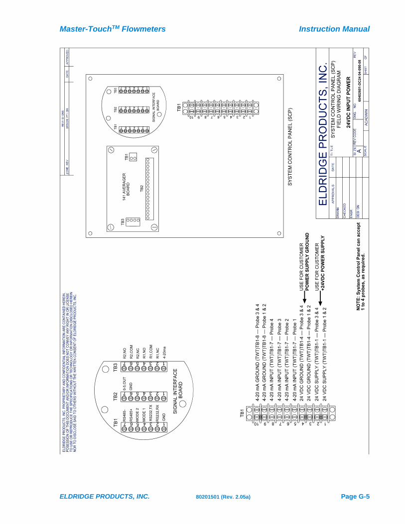
Master-TouchTM Flowmeters Instruction Manual
ELDRIDGE PRODUCTS, INC. 80201501 (Rev. 2.05a) Page G-5

Instruction Manual Master-TouchTM Flowmeters
Page G-6 80201501 (Rev. 2.05a) ELDRIDGE PRODUCTS, INC.
5134 2
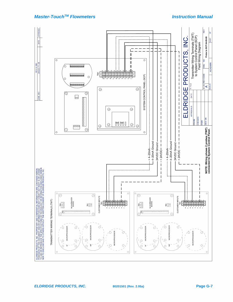
Master-TouchTM Flowmeters Instruction Manual
ELDRIDGE PRODUCTS, INC. 80201501 (Rev. 2.05a) Page G-7
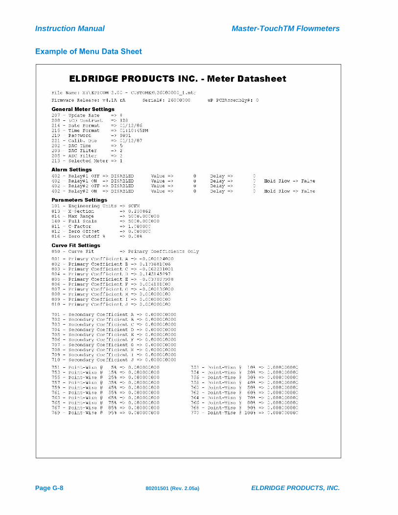
Instruction Manual Master-TouchTM Flowmeters
Page G-8 80201501 (Rev. 2.05a) ELDRIDGE PRODUCTS, INC.
Example of Menu Data Sheet

Master-TouchTM Flowmeters Instruction Manual
ELDRIDGE PRODUCTS, INC. 80201501 (Rev. 2.05a) Page G-9
Menu Item Interaction
One of the strengths of the Master-Touch™ flowmeters is the extensive support for users’
adjustments to the menu item settings. Although various menu items, such as the alarm relays, are
used in conjunction with one or more other menu items, most of the individual menu item values can
be changed without affecting any other settings. However, changing the engineering units (menu
items 101–132) or changing the cross-sectional area (menu item 813–SetXSect) will prompt the
microprocessor to immediately recalculate the Full Scale (menu item 140–FScale) and Maximum
Range (menu item 814–MaxRange) values. In addition, the proper sequence should be followed when
making changes such as these:
1) Engineering Units (menu items 101–132),
2) Cross-sectional Area (menu item 813–SetXSect),
3) Full Scale (menu item 140–FScale)
The cross-sectional area of an inline style flowmeter must not be changed, and the
Full Scale value must not be greater than the re-calculated Maximum Range.
Master-Touch™ Diagnostics
Although it is prudent to periodically send meters back for recalibration (typically 1 year is
recommended), the Master-Touch™ has a variety of diagnostic menus to allow you to conduct your
own interim verifications. For example, Menu 204 (the DAC readout) provides an on-board (filtered
and unfiltered) voltage signal proportional to the linear 0-5 VDC full scale range that can be viewed
with a lap top. Use EPICommunicator to help with this process. If the user has a calibration facility
that can generate a stable flow rate (below the specified full scale range), you can note and record the
meter’s Menu 204 when the meter is new. Three months or six months later, you can repeat the test.
If you receive a similar result, you can be assured that the meter has not drifted out of calibration.
The same check should be done with Menu 206, (the ADC readout), although its value will be higher
due to the non-linearity of the basic flow signal. Finally, you always have the option of checking the
bridge voltage at zero flow. The meter should be oriented in the same orientation as its original
calibration at Eldridge — with enclosure up and display/keypad facing towards you. There should be
no flow, and the line pressure should be at the original calibration pressure. If the BV measurement
off of the left side of resistor RFU and ground is the same as the original BV as recorded by Eldridge,
this is another indication that the meter is still in calibration.

Instruction Manual Master-TouchTM Flowmeters
Page G-10 80201501 (Rev. 2.05a) ELDRIDGE PRODUCTS, INC.
Master-TouchTM Auto-Ranging (External Mode)
The diagram below shows the wiring diagram for the auto-ranging circuit. This circuit works with
the flowmeter’s External Mode selection. The result is to automatically change the meter range in
the Master-Touch™ based on flow rate, and thereby set a different scale for the 0–5VDC and 4–
20mA output signals. This change will not have any effect on the accuracy of the flow rate shown on
the flowmeter's LCD display. This method assumes:
1) Meter ranges #1 & #2 are programmed into the flowmeter and that Meter #1 has a lower Full
Scale than Meter #2.
2) The customer will add the external relays. These can be mounted outside the enclosure if they do
not fit under the enclosure cover.
Use EPI Relay #2 when in Meter #1. Set this relay to trip at the “high” value. When the flow rate
goes above this value, it will trip the relay which will then switch the flowmeter to Meter #2. The
flowmeter will run through its reset routine and re-start in Meter Range 2. Disable Relay #1 in
Meter Range 1.
Use EPI Relay #1 when in Meter #2. Set this relay to trip at the “low” value. When the flow rate goes
below this value, it will trip the relay which will then switch the flowmeter to Meter #1. The
flowmeter will run through its reset routine and re-start in Meter Range 1. Disable Relay #2 in
Meter Range 2.
The “high” and “low” values set for the relays must be the same. To avoid unwanted cycling between
the two ranges if the actual flow rate stays too close to the trip point, set a time delay on the relay
response.
After setting up the relays, the flowmeter must be set to External Mode (see Section D,
Menu 213–Set Meter) and the customer relay connected to Ground and Mode 2 select.

Master-TouchTM Flowmeters Instruction Manual
ELDRIDGE PRODUCTS, INC. 80201501 (Rev. 2.05a) Page G-11
Master-TouchTM ASCII Data Stream
The following is an example of the fixed width ASCII data stream continuously transmitted from the
Master-Touch™ microprocessor:
21.98• • • • SCFM• • • • 239184.68952• SCF• • • 962.15• • • • • • 0.00• • • • • R1=.• R2=.• • • • • •
22.48• • • • SCFM• • • • 239184.85641• SCF• • • 962.15• • • • • • 0.00• • • • • R1=.• R2=.• • • • • •
22.56• • • • SCFM• • • • 239184.99947• SCF• • • 962.15• • • • • • 0.00• • • • • R1=.• R2=.• • • • • •
23.71• • • • SCFM• • • • 239185.21404• SCF• • • 962.15• • • • • • 0.00• • • • • R1=.• R2=.• • • • • •
23.83• • • • SCFM• • • • 239185.35709• SCF• • • 962.15• • • • • • 0.00• • • • • R1=.• R2=.• • • • • •
24.42• • • • SCFM• • • • 239185.59551• SCF• • • 962.15• • • • • • 0.00• • • • • R1=*• R2=.• • • • • •
26.86• • • • SCFM• • • • 239185.76241• SCF• • • 962.15• • • • • • 0.00• • • • • R1=*• R2=.• • • • • •
The following describes the data stream elements:
26.86• • • • SCFM• • • • 239185.76241• SCF• • • 962.15• • • • • • 0.00• • • • • R1=*• R2=.• • • • • •
Flow Rate
26.86• • • • SCFM• • • • 239185.76241• SCF• • • 962.15• • • • • • 0.00• • • • • R1=*• R2=.• • • • • •
Elapsed Total
26.86• • • • SCFM• • • • 239185.76241• SCF• • • 962.15• • • • • • 0.00• • • • • R1=*• R2=.• • • • • •
Highest Flow
26.86• • • • SCFM• • • • 239185.76241• SCF• • • 962.15• • • • • • 0.00• • • • • R1=*• R2=.• • • • • •
Lowest Flow
26.86• • • • SCFM• • • • 239185.76241• SCF• • • 962.15• • • • • • 0.00• • • • • R1=*• R2=.• • • • • •
Relay #1 Status
26.86• • • • SCFM• • • • 239185.76241• SCF• • • 962.15• • • • • • 0.00• • • • • R1=*• R2=.• • • • • •
Relay #2 Status
The flowmeter can also be controlled by sending the various menu commands and values to the
Master-Touch™ as an ASCII stream. These communications could be transmitted through either the
RS232 or RS485 communications protocols but, without EPI's full menuing system, the commands
must be sent "blind" after referring to the Instruction Manual for the proper sequence of input
characters.

GAS MASS FLOW MEASUREMENT & CONTROL INSTRUMENTATION
465 RESERVATION ROAD ◼ MARINA, CA 93933 ◼ [831] 648-7777 ◼ FAX [831] 648-7780
www.epiflow.com
CUSTOMER SATISFACTION REPORT
Eldridge Products, Inc. is interested in your level of satisfaction with the purchase and operation of your
new thermal gas mass flow meter(s) or switch(es). Please take a few moments to complete the following
form and then either fax or mail it to EPI. Thank you for your cooperation.
Your Name: Instrumentation
Serial Number(s):
Company:
Date:
Fax No.:
Tel. No.:
Sales Order:
Did you receive a confirming Sales Order from Eldridge Products, Inc. for your review that was correct in
its details for invoicing, order shipment, and the technical details of the required instrumentation?
Yes ___ No (Please explain):
Order Shipment:
Did you receive all instrumentation as ordered and per the Purchase Order shipping instructions?
Yes ___ No (Please explain):
Instrument Performance:
Did the instrumentation perform in accordance within factory specifications?
Yes ___ No (Please explain):