series 900 road pavements – bituminous bound€¦ · 936 (07/19) geosynthetics and steel meshes:...
TRANSCRIPT
MANUAL OF CONTRACT DOCUMENTS FOR HIGHWAY WORKS VOLUME 1 SPECIFICATION FOR HIGHWAY WORKS
Amendment – July 2019 1
SERIES 900 ROAD PAVEMENTS – BITUMINOUS BOUND MATERIALS
Contents
Clause Title Page
900 (05/18) General 3
901 (05/18) Bituminous Mixtures 3
902 (05/18) Reclaimed Asphalt 5
903 (05/18) Placing and Compaction of Bituminous Mixtures 6
904 (05/18) Hot Rolled Asphalt Base 9
905 (05/18) Hot Rolled Asphalt Binder Course (Recipe Mixtures) 9
906 (05/18) Dense Base and Binder Course Asphalt Concrete with Paving Grade Bitumen (Recipe Mixtures) 9
907 (05/18) Regulating Course 10
908 (05/18) Not Used 10
909 (05/18) 6 mm Dense Asphalt Concrete Surface Course 10
910 (05/18) Hot Rolled Asphalt Surface Course (Recipe Mixtures) 10
#911 (05/18) Hot Rolled Asphalt Surface Course (Design Mixtures) 11
912 (05/18) Close Graded Asphalt Concrete Surface Course 12
913 (05/18) Not Used 12
914 (05/18) Fine Graded Asphalt Concrete Surface Course 12
915 (05/18) Coated Chippings for Application to Hot Rolled Asphalt Surfacings 12
916 & 917 (05/18) Not Used 12
918 (05/18) Slurry Surfacing Incorporating Microsurfacing 12
919 (05/18) Surface Dressing: Recipe Specification� 16
920 (05/18) Bond Coats, Tack Coats and Other Bituminous Sprays 19
921 (05/18) Surface Macrotexture of Bituminous Surface Courses 20
1
Clause Title Page
922 (05/18) Surface Dressing: Design, Application and End Product Performance 22
923 (05/18) Cold Applied Ultra-Thin Surfacing 24
924 (05/18) High Friction Surfaces 27
925 (05/18) Testing of Bituminous Mixtures 28
926 (05/18) In Situ Recycling: The Repave Process 28
927 & 928 (05/18) Not Used 28
929 (05/18) Dense Base and Binder Course Asphalt Concrete (Design Mixtures) 28
930 (05/18) EME2 Base and Binder Course Asphalt Concrete 30
931 to 935 (07/19) Not Used 33
936 (07/19) Geosynthetics and Steel Meshes: Installation and End Product Performance 33
937 (05/18) Stone Mastic Asphalt (SMA) Binder Course and Regulating Course 36
938 (05/18) Porous Asphalt 37
939 to 941 (05/18) Not Used 38
#942 (05/18) Thin Surface Course Systems 38
943 (05/18) Hot Rolled Asphalt Surface Course and Binder Course (Performance-Related Design Mixtures) 44
944 (05/18) Not Used 45
945 (05/18) Weather Conditions for Laying of Bituminous Mixtures 45
946 (05/18) Local Repairs 46
947 (05/18) In Situ Cold Recycled Bound Material 48
948 (05/18) Ex Situ Cold Recycled Bound Material 56
949 (05/18) Not Used 61
950 (05/18) Surface Preservation Systems 61
MANUAL OF CONTRACT DOCUMENTS FOR HIGHWAY WORKS VOLUME 1 SPECIFICATION FOR HIGHWAY WORKS
2Amendment – July 2019
Clause Title Page
951 (05/18) Torque Bond Test 62
952 & 953 (05/18) Not Used 63
954 (05/18) Method for Laboratory Determination of Interface Properties Using�the�Modified�Leutner�Shear�Test� 63
955 (05/18)�Ageing�Profile�Test�Using�a� Modified�Rolling�Thin�Film�Oven�Test�(MRTFOT) 67
956 & 957 (05/18) Not Used 77
958 (05/18)�Modified�Binder�Storage� Stability Test 77
NATIONAL ALTERATIONS OF THE OVERSEEING ORGANISATIONS OF SCOTLAND, WALES AND NORTHERN IRELANDClause Title Page
911TS/WG (05/18) Hot Rolled Asphalt Surface Course (Design Mixtures) 79F
942TS (05/18) Stone Mastic Asphalt Surface Course (TS2010) 79F
#� denotes�a�Clause�or�Sample�Contract�Specific�Appendix�which�has�a�substitute�National�Clause�or�Sample�Contract�Specific�Appendix for one or more of the Overseeing Organisations of Scotland, Wales or Northern Ireland.

Volume 1 Series 900 Specification for Highway Works Road Pavements – Bituminous Bound Materials
Amendment – May 2018 3
ROAD PAVEMENTS – BITUMINOUS BOUND MATERIALS
900 (05/18) General
1 (05/18)�This�Series�is�part�of�the�Specification�for�Highway�Works.�Whilst�this�Series�is�particularly�relevant�to�the subject matter in its title it must be read in conjunction with the general requirements in Series 000 and 100 and with�all�other�Series�relevant�to�the�specification�for�the�particular�works�to�be�undertaken.
901 (05/18) Bituminous Pavement Mixtures
(05/18) General
1 (05/18) This Clause gives general requirements for the properties of the aggregates and bitumen used in plant-produced bituminous mixtures. These requirements apply to all plant produced bituminous mixtures unless otherwise�specified�in�contract�specific�Appendix�7/1�or�where�other�requirements�are�given�in�specific�Clauses�in�this Series.
2 (05/18) Bituminous mixtures shall be laid by organisations registered to and operating in compliance with the ‘Sector Scheme 16 for the Laying of Asphalt Mixes’ listed in Appendix A. All mixtures supplied in accordance with BS EN 13108 shall be CE marked and the Contractor shall submit the declaration of performance which shall demonstrate�that�the�mixture�provides�the�performance�required�by�the�specification.
(05/18) Aggregates for Bituminous Mixtures
3 (05/18)�Natural,�recycled�unbound�and�manufactured�(artificial)�aggregates�shall�be�clean,�hard�and�durable�and�shall comply with BS EN 13043:2002 and be CE marked and have a declared performance which demonstrates that the�aggregate�meets�the�requirements�of�the�specification.�Where�recycled�coarse�aggregate�or�recycled�concrete�aggregate is used in bituminous mixtures, it shall have been tested in accordance with Clause 710 and the content of other materials (Class X) including wood, plastic and metal shall not exceed 1% by mass. Reclaimed asphalt shall comply with Clause 902.
4 (05/18) The use of aggregate derived as a by-product during the extraction of china clay is permitted. It shall comply with the requirements of this Clause, BS EN 13043:2002 and the examples of the relevant annex of BSI PD 6691.
5 (05/18) The use of crushed slate aggregate is permitted in base and binder course layers. It shall comply with the requirements of this Clause, BS EN 13043:2002 and the examples of the relevant annex of BSI PD 6691, except for the�flakiness�category,�which�shall�be�subject�to�prior�approval�by�the�Overseeing�Organisation.�Mixtures�of�crushed�slate aggregate with coarse aggregate of a different geological type shall not be permitted.
(05/18) Resistance to Fragmentation (Hardness)
6 (05/18)�Unless�otherwise�stated�in�contract�specific�Appendix�7/1�the�coarse�aggregates�for�bituminous�mixtures�shall meet the following criteria:
(i)� the�resistance�to�fragmentation�category�of�the�coarse�aggregate�as�defined�in�clause�4.2.2�of�BS EN 13043:2002 shall be LA30 or better for natural aggregates and LA50 or better for blast furnace slag;
or
(ii) crushed rock aggregate has a Los Angeles Value greater than 30 but less than 35, where evidence can be presented to the Overseeing Organisation of previous satisfactory use of the source in asphalt.

Volume 1 Series 900 Specification for Highway Works Road Pavements – Bituminous Bound Materials
4Amendment – July 2019
Natural�and�manufactured�(artificial)�aggregates�recovered�from�a�previous�use�in�an�unbound�form�shall�comply�with the requirements of this Clause.
(05/18) Resistance to Freezing and Thawing (Durability)
7 (05/18)�When�required�in�contract�specific�Appendix�1/5,�the�resistance�of�the�coarse�aggregate�to�freezing�and�thawing�shall�be�declared.�The�freezing�and�thawing�(soundness)�category,�as�defined�in�BS�EN�13043:2002,�clause 4.2.9.2, shall be MS25�unless�otherwise�specified�in�contract�specific�Appendix�7/1.�The�water�absorption�value of the coarse aggregate shall be determined in accordance with BS EN 13043:2002, clause 4.2.9.1. If the water absorption value of the coarse aggregate is greater than WA242, the soundness test shall be carried out on the material delivered to site. The requirements for water absorption do not apply to blast furnace slag aggregate.
(05/18) Cleanness
8 (05/18)�Unless�otherwise�specified�in�contract�specific�Appendix�7/1,�the�proportion�of�coarse�and�fine�aggregates�for�bituminous�mixtures�passing�the�0.063�mm�test�sieve�(fines�content)�shall�not�exceed�the�limits�stated in BSI PD 6691 Annex B, Annex C and Annex D, when tested in accordance with the washing and sieving method of BS EN 933-1.
(05/18) Resistance to Polishing and Surface Abrasion
9 (05/18)�When�specified�in�the�appropriate�Clause�or�contract�specific�Appendix�7/1,�the�aggregate�shall�conform�to the required declared PSV category in accordance with BS EN 13043:2002 clause 4.2.3 and BSI PD 6682-2 clause 4.3.2.
10 (05/18) The resistance to surface abrasion of coarse aggregate used in surface courses in accordance with BS EN 13043 clause 4.2.3 and BSI PD 6682-2 clause 3.3.3, shall conform to category AAV10 unless otherwise specified�in�the�appropriate�Clause�or�in�contract�specific�Appendix�7/1.
(05/18) Chemical Requirements
(05/18) Dicalcium Silicate Disintegration
11 (05/18) Air-cooled blast furnace slag aggregates shall be free from iron dicalcium silicate disintegration as defined�in�BS�EN�13043:2002,�clause�4.3.4.1.
(05/18) Iron Disintegration
12 (05/18)�Air-cooled�blast�furnace�slag�aggregates�shall�be�free�from�iron�disintegration�as�defined�in�BS EN 13043:2002, clause 4.3.4.2.
(05/18) Volume Stability
13 (05/18)�The�volume�stability�category�of�steel�slag�aggregates�as�defined�in�BS�EN�13043,�clause�4.3.4.3�shall�not exceed V10.
(05/18) Bitumen
14 (05/18) Paving grade bitumen shall comply with BS EN 12591.
15 (05/18)�Polymer�modified�bitumen�shall�comply�with�BS�EN�14023.
(05/18) Asphalt Durability
16 (05/18) The durability of adhesion in base and binder course mixtures designed in accordance with Clause 929 and to be used on trunk roads including motorways shall be determined by testing in accordance with BS EN 12697-45. The SATS Durability Index of the mix components shall be above 80%.
17 (05/18)�Mixtures�that�include�2%�hydrated�lime�filler�are�deemed�to�satisfy�this�requirement�and�SATS�testing�is�not�required.�Hydrated�lime�filler�shall�be�Ca�(OH)2 in the form of hydrated lime, type CL 90-S.
Volume 1 Series 900 Specification for Highway Works Road Pavements – Bituminous Bound Materials
Amendment – May 2018 5
902 (05/18) Reclaimed Asphalt
1 (05/18) The requirements of this clause apply to all bituminous mixtures containing reclaimed asphalt.
2 (05/18) Reclaimed asphalt may be used in the production of bituminous surface course, binder course, regulating�course�and�base.�Unless�otherwise�specified�in�contract�specific�Appendix�7/1,�the�use�of�reclaimed�asphalt shall be in accordance with:
(i)� Clause�942�for�surface�course�mixtures�specified�in�Clause�942;
(ii) BSI PD 6691, B.2.4.4 for Asphalt Concrete mixtures (macadams);
(iii) BSI PD 6691, C.2.3.4 for Hot Rolled Asphalt mixtures;
(iv) BSI PD 6691, D.2.2.3 for Stone Mastic Asphalt mixtures.
Other recycled materials shall only be used in bituminous mixtures with the approval of the Overseeing Organisation. The mixed material shall comply with the requirements of all the relevant Clauses in this Series.
(05/18) Reclaimed Feedstock
3 (05/18) All reclaimed material shall be pre-treated before use such that it is homogeneously mixed and the maximum�particle�size�does�not�exceed�32�mm.
(05/18) Properties of Binder
4 (05/18) The fresh bitumen added to the mixture shall not be more than two grades softer than the nominal grade for the mixture given in Table 12 of BSI PD 6691. Checks on the penetration of the binder recovered from the reclaimed asphalt, together with a calculation of the properties of the combined binder, shall be carried out in accordance with the relevant parts of BS EN 13108. When more than 10% of reclaimed asphalt is incorporated in a mixture, tests on binder recovered from the mixture shall be carried out following the example in BSI PD 6691 13.3.6.2. The results shall be within the limits set out in BSI PD 6691 13.3.6.2.
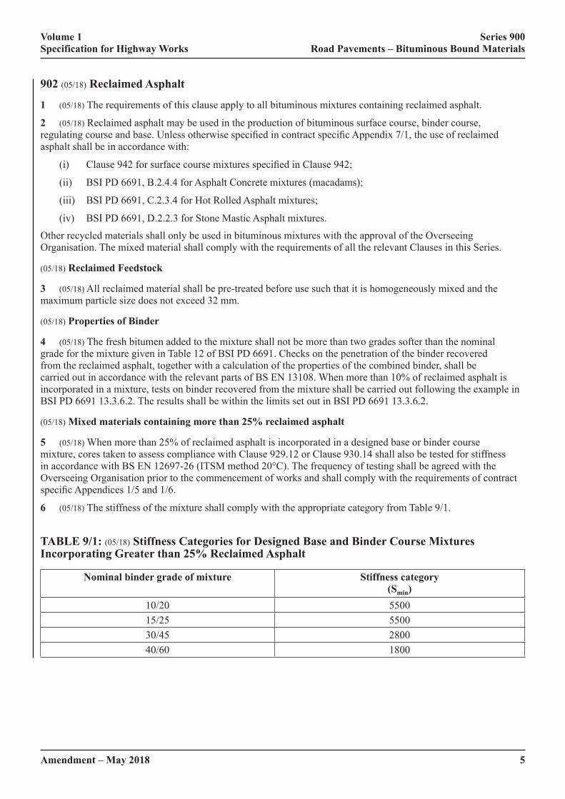
(05/18) Mixed materials containing more than 25% reclaimed asphalt
5 (05/18) When more than 25% of reclaimed asphalt is incorporated in a designed base or binder course mixture, cores taken to assess compliance with Clause 929.12 or Clause 930.14 shall also be tested for stiffness in accordance with BS EN 12697-26 (ITSM method 20°C). The frequency of testing shall be agreed with the Overseeing Organisation prior to the commencement of works and shall comply with the requirements of contract specific�Appendices�1/5�and�1/6.
6 (05/18) The stiffness of the mixture shall comply with the appropriate category from Table 9/1.
TABLE 9/1: (05/18) Stiffness Categories for Designed Base and Binder Course Mixtures Incorporating Greater than 25% Reclaimed Asphalt
Nominal binder grade of mixture Stiffness category (Smin)
10/20 550015/25 550030/45 280040/60 1800

Volume 1 Series 900 Specification for Highway Works Road Pavements – Bituminous Bound Materials
6Amendment – May 2018
903 (05/18) Placing and Compaction of Bituminous Mixtures
(05/18) General
1 (05/18) This Clause gives general requirements for the placing and compaction of bituminous mixtures, which are complementary and additional to the requirements of BS 594987. These requirements and the requirements of�BS�594987�apply�to�all�bituminous�mixtures,�unless�otherwise�specified�in�the�other�Clauses�in�this�Series�or�in�contract�specific�Appendix�7/1.
2 (05/18)�Bituminous�pavements�shall�be�constructed�using�the�materials�specified�in�contract�specific�Appendix 7/1 and shall be laid by contractors that are registered to the BS EN ISO 9001 ‘Sector Scheme 16 for the Laying of Asphalt Mixes’ listed in Appendix A.
3 (05/18) In order to exclude moisture from interfaces and ensure full interlayer bonding, the surface of all bituminous material shall be kept clean and uncontaminated. Unless agreed with the Overseeing Organisation, the only�traffic�permitted�to�run�on�the�surface�of�bituminous�material�to�be�overlaid�shall�be�that�engaged�in�laying�and compacting the next course or, where a binder course is to be blinded or surface dressed, that is engaged on such surface treatment. If any surface becomes contaminated, it shall be made good by cleaning and, if this proves impracticable,�by�rectification�in�compliance�with�Clause�702.
4 (05/18) Prior to placing bituminous material on any new or existing bound substrate, a bond coat or tack coat shall be applied in accordance with Clauses 920 or 942, as appropriate.
5 (05/18) Before work commences, the Contractor shall submit a method statement to the Overseeing Organisation that includes:
(i)� Laying�and�compaction�procedures�for�each�layer�–�including�paving�speed�and�paved�width;�size,�type�and number of rollers; and number of roller passes.
(ii) The joint formation procedures for each layer – including the location of longitudinal and transverse joints; and the method(s) of treating upstanding edges.
(05/18) Transporting
6 (05/18) Hot bituminous mixtures shall be transported in accordance with the requirements of BS 594987 and shall remain covered whilst awaiting tipping.
(05/18) Laying
7 (05/18)�Hot�bituminous�mixtures,�other�than�those�specified�under�Clause�942,�shall�be�laid�in�accordance�with�the�requirements�of�BS�594987�and�sub-Clauses�8�to�14�of�this�Clause.�Surfacings�specified�under�Clause�942�shall�be laid in accordance with the requirements of that Clause and sub-Clauses 8 to 14 of this Clause.
8 (05/18) Wherever practicable, hot bituminous mixtures shall be spread, levelled and tamped by a self-propelled paving machine. The rate of delivery of material to the paver shall be regulated to enable the paver to operate continuously.
9 (05/18) Hand placing of hot bituminous mixtures shall be restricted to the following circumstances:
(i) For laying regulating courses of irregular shape and varying thickness.
(ii)� In�confined�spaces�where�it�is�impracticable�for�a�paver�to�operate.
(iii) For footways.
(iv) At the approaches to expansion joints at bridges, viaducts or other structures.
(v) For laying mastic asphalt.
10 (05/18) Hand-raking of surface course material or the addition of such material by hand-spreading to the paved area, for adjustment of level, shall be restricted to the following circumstances:
(i) At the edges of the layers of material and at gullies, manholes and other ironwork.
Volume 1 Series 900 Specification for Highway Works Road Pavements – Bituminous Bound Materials
Amendment – May 2018 7
(ii) At the approaches to expansion joints at bridges, viaducts or other structures.
11 (05/18)�The�method�of�laying�shall�be�such�that�the�finished�mat�is�free�from�dragging,�tearing�and�segregation�of the material.
12 (05/18) When laying mixtures from more than one source, the mixtures shall have equivalent laying and compaction characteristics so that surface evenness is not compromised.
13 (05/18) When paving adjacent to an expansion joint of a structure, the joint or joint cavity shall be kept clear of material. When laying binder course or surface course, the paver shall be taken out of use whilst laying the remainder of the pavement up to the joint and the corresponding area beyond it.
14 (05/18)�When�paving�directly�onto�bridge�deck�waterproofing�systems,�any�special�requirements�which�apply�to�that system shall be complied with.
(05/18) Compaction
15 (05/18) The compaction of hot bituminous mixtures shall be in accordance with BS 594987 and the requirements�for�specific�mixtures�in:
(i) Clause 929 for dense base and binder course asphalt concrete (design mixtures).
(ii) Clause 930 for EME2 mixtures.
(iii) Clause 942 for thin surface course systems.
16 (05/18)�Except�where�otherwise�specified,�rollers�shall�comply�with�the�general�requirements�of�BS�594987�except that the minimum mass of deadweight smooth wheeled rollers shall be 8 tonnes. Multi-wheeled pneumatic-tyred rollers and vibratory rollers may be used if they are capable of achieving at least the standard of compaction of an 8-tonnes deadweight roller.
17 (05/18) Where compaction is to be determined in accordance with Clauses 929 and 930, the requirements to prove the performance of rollers do not apply. In such cases, the Contractor may use any plant to achieve the specified�level�of�compaction�and�shall�finish�compaction�at�temperatures�above�the�minimum�specified�rolling�temperature.
18 (05/18) Vibratory rollers shall not be used in vibrating mode on bridge decks.
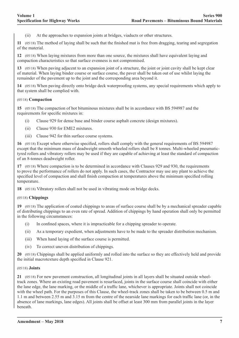
(05/18) Chippings
19 (05/18) The application of coated chippings to areas of surface course shall be by a mechanical spreader capable of distributing chippings to an even rate of spread. Addition of chippings by hand operation shall only be permitted in the following circumstances:
(i)� In�confined�spaces,�where�it�is�impracticable�for�a�chipping�spreader�to�operate.
(ii) As a temporary expedient, when adjustments have to be made to the spreader distribution mechanism.
(iii) When hand laying of the surface course is permitted.
(iv) To correct uneven distribution of chippings.
20 (05/18) Chippings shall be applied uniformly and rolled into the surface so they are effectively held and provide the�initial�macrotexture�depth�specified�in�Clause�921.
(05/18) Joints
21 (05/18) For new pavement construction, all longitudinal joints in all layers shall be situated outside wheel-track�zones.�Where�an�existing�road�pavement�is�resurfaced,�joints�in�the�surface�course�shall�coincide�with�either�the�lane�edge,�the�lane�marking,�or�the�middle�of�a�traffic�lane,�whichever�is�appropriate.�Joints�shall�not�coincide�with�the�wheel�path.�For�the�purposes�of�this�Clause,�the�wheel-track�zones�shall�be�taken�to�be�between�0.5�m�and�1.1�m�and�between�2.55�m�and�3.15�m�from�the�centre�of�the�nearside�lane�markings�for�each�traffic�lane�(or,�in�the�absence of lane markings, lane edges). All joints shall be offset at least 300 mm from parallel joints in the layer beneath.

Volume 1 Series 900 Specification for Highway Works Road Pavements – Bituminous Bound Materials
8Amendment – July 2019
22 (05/18)�Unless�otherwise�specified�in�contract�specific�Appendix�7/1,�the�faces�of�all�cold�upstanding�edges,�including previously laid asphalt, against which hot bituminous mixtures are to be laid to form joints shall be treated with one of the following:
(i) hot bituminous binder with a penetration of not less than 40 pen;
(ii)� hot�elastomeric�polymer-modified�bituminous�binder�complying�with�BS�EN�14023�with�a�penetration�of not less than 40 pen;
(iii)� cold�applied�thixotropic�bituminous�compound�of�similar�bitumen�or�polymer-modified�bitumen�grade;
(iv)� polymer-modified�adhesive�bitumen�strip�with�a�minimum�thickness�of�2�mm.
This operation shall be done so that the binder adheres to both the cold and the warm upstanding edges when the asphalt is placed.
23 (05/18)�Unless�otherwise�specified�in�contract�specific�Appendix�7/1,�joints�in�binder�courses�and�bases�shall�be compacted such that the air voids content measured from core pairs whose centres are not more than 100 mm from�the�final�joint�is�not�greater�than�2%�above�the�maximum�permitted�limit�for�core�pairs�in�the�body�of�the�mat.�The air voids content shall be calculated in accordance with BS EN 12697-8 using the relevant bulk and maximum densities�defined�in�Appendix�B�of�BS�EN�13108-20�for�the�relevant�mixture�type.
24 (05/18) Within 24 hours of the joint being formed, a sealant shall be applied to the top surface of all base and binder course joints such that there is not less than 0.50 kg/m2 of residual bitumen 75 mm either side of the joint, unless�otherwise�specified�in�contract�specific�Appendix�7/1.�The�sealant,�which�may�contain�mineral�filler�to�BS EN 13043, shall be one of the following:
(i)� hot�elastomeric�polymer-modified�bituminous�binder�complying�with�BS�EN�14023�with�a�penetration�of not less than 40 pen;
(ii) bitumen emulsion with a cohesion by pendulum of Class 4 or above in accordance with BS EN 13808;
(iii) slurry surfacing complying with Clause 918.
25 (05/18)�Unless�otherwise�specified�in�contract�specific�Appendix�7/1,�a�sealant,�as�specified�in�sub-Clause�24�of�this�Clause,�shall�be�applied�to�the�whole�of�any�freestanding�edge�on�the�outside�of�the�finished�pavement�on�the�high�side�of�the�camber�and,�when�specified�in�contract�specific�Appendix�7/1,�on�the�low�side.
(05/18) Regulating Course
26 (05/18) Regulating course material shall be made and laid in accordance with the requirements of Clause 907.
(05/18) Use of Surfaces by Traffic
27 (05/18)�Where�a�new�bituminous�layer�other�than�the�surface�course�is�to�be�opened�to�highway�traffic�as�a�temporary running surface it shall either:
(i) be surface dressed in accordance with Clause 919 using chippings of category not less than PSV50, unless�otherwise�specified�in�contract�specific�Appendix�7/1;�or
(ii) contain a coarse aggregate of category of not less than PSV50,�unless�otherwise�specified�in�contract�specific�Appendix�7/1.
28 (05/18)�Construction�plant�and�traffic�used�on�pavements�under�construction�shall�be�suitable�in�relation�to�the�material, condition and thickness of the courses it traverses so that damage is not caused to the subgrade or the pavement courses already constructed. The wheels or tracks of plant moving over the various pavement courses shall be kept free from deleterious materials.
(07/19) Warm Mix Asphalts (WMA)
29 (07/19) WMAs are proposed to be delivered to site and rolled at lower temperatures than those recommended by Table A.1 of BS 594987:2015 + A1:2017 and in line with the producer’s recommendations.

Volume 1 Series 900 Specification for Highway Works Road Pavements – Bituminous Bound Materials
9Amendment – July 2019
30 (07/19) WMA materials shall be produced in accordance with:
(i) Clause 906 Dense Base and Binder Course Asphalt Concrete with Paving Grade Bitumen (Recipe Mixtures);
(ii) Clause 912 Close Graded Asphalt Concrete Surface Course;
(iii) Clause 929 Dense Base and Binder Course Asphalt Concrete (Design Mixtures);
(iv) Clause 930 EME2 Base and Binder Course Asphalt Concrete;
(v) Clause 937 Stone Mastic Asphalt (SMA) Binder Course and Regulating Course;
(vi) Clause 942 Thin Surface Course Systems;
and shall comply with Clause 902 and 903.
31 (07/19) Water sensitivity of the Clause 942 Thin Surface Course System mixtures shall be assessed in accordance with BS EN 12697-12 (Method A) prior to the commencement of works. The Indirect Tensile Strength Ratio (ITSR) obtained shall be greater than or equal to ITSRmin80.
32 (07/19)�Warm�mixtures�conforming�to�Clause�942�shall�have�Product�Acceptance�Scheme�certification�for�their�installation in compliance with sub-Clause 104.16 and Clause 942 to demonstrate their performance.
904 (05/18) Hot Rolled Asphalt Base
1 (05/18) Hot Rolled Asphalt base recipe mixes shall conform to BS EN 13108-4, the detailed requirements of the�example�in�BSI�PD�6691�Annex�C�and�requirements�specified�in�contract�specific�Appendix�7/1.�The�mixture�designation shall be one of the following:
(i) HRA 60/32 base 40/60.
(ii) HRA 60/32 base 30/45.
(iii) HRA 60/20 base 40/60.
(iv) HRA 60/20 base 30/45.
905 (05/18) Hot Rolled Asphalt Binder Course (Recipe Mixtures)
1 (05/18) Hot Rolled Asphalt binder course recipe mixes shall conform to BS EN 13108-4, the example in BSI�PD�6691�Annex�C�and�requirements�specified�in�contract�specific�Appendix�7/1.�The�mixture�designation�shall�be one of the following:
(i) HRA 60/32 bin 40/60.
(ii) HRA 60/32 bin 30/45.
(iii) HRA 60/20 bin 40/60.
(iv) HRA 60/20 bin 30/45.
906 (05/18) Dense Base and Binder Course Asphalt Concrete (Recipe Mixtures)
1 (05/18) Dense base and binder course asphalt concrete (formerly macadam) recipe mixtures shall be asphalt concrete conforming to BS EN 13108-1, the detailed requirements from BSI PD 6691 Annex B and requirements specified�in�contract�specific�Appendix�7/1.�The�mixture�designation�shall�be�one�of�the�following:
(i) AC 32 dense base 40/60 rec.
(ii) AC 32 dense base 100/150 rec.
Volume 1 Series 900 Specification for Highway Works Road Pavements – Bituminous Bound Materials
10Amendment – May 2018
(iii) AC 32 dense base 160/220 rec.
(iv) AC 32 dense bin 40/60 rec.
(v) AC 32 dense bin 100/150 rec.
(vi) AC 32 dense bin 160/220 rec.
(vii) AC 20 dense bin 40/60 rec.
(viii) AC 20 dense bin 100/150 rec.
(ix) AC 20 dense bin 160/220 rec.
907 (05/18) Regulating Course
1 (05/18) Regulating courses, which may consist of one or more layers of a bituminous material, shall have their finished�surfaces�laid�to�achieve�the�appropriate�tolerances�for�horizontal�alignments,�surface�levels�and�surface�regularity for pavement layers, in accordance with Clause 702.
2 (05/18)�Unless�otherwise�specified�in�contract�specific�Appendix�7/1,�stone�mastic�asphalt�complying�with�Clause 937, or base or binder course asphalt concrete complying with Clause 929 or hot rolled asphalt complying with Clause 943, shall be used for regulating courses immediately below surface courses. Bituminous mixtures for regulating�courses�shall�meet�the�requirements�for�the�appropriate�material,�as�specified�above.
3 (05/18) Where the total depth of a regulating course exceeds 150 mm then the course shall be laid so that each regulating layer has a compacted thickness of between 75 mm and 150 mm.
908 (05/18) Not Used
909 (05/18) 6 mm Dense Asphalt Concrete Surface Course
1 (05/18) 6 mm dense asphalt concrete (formerly macadam) surface course shall be asphalt concrete conforming to�BS�EN13108-1,�the�example�in�BSI�PD�6691�Annex�B�and�requirements�specified�in�contract�specific�Appendix 7/1. The mixture designation shall be one of the following:
(i) AC 6 dense surf 100/150.
(ii) AC 6 dense surf 70/100.
(05/18) Coarse Aggregate
2 (05/18) To ensure adequate resistance to polishing and abrasion, the coarse aggregate shall have a minimum declared�PSV�as�specified�in�contract�specific�Appendix�7/1,�in�accordance�with�BS�EN�13043:2002,�clause�4.2.3.�and�BSI�PD�6682-2,�and�shall�have�a�maximum�declared�AAV,�as�specified�in�contract�specific�Appendix�7/1,�in�accordance with BS EN 13043:2002, clause 4.2.4 and BSI PD 6682-2.
910 (05/18) Hot Rolled Asphalt Surface Course (Recipe Mixtures)
1 (05/18) Hot Rolled Asphalt surface course recipe mixtures shall conform to BS EN 13108-4, the example of�BSI�PD�6691�Annex�C,�and�the�requirements�specified�in�contract�specific�Appendix�7/1.�Unless�otherwise�specified�in�contract�specific�Appendix�7/1,�the�mixture�designation�shall�be�one�of�the�following:
(i) HRA 0/2 F surf 40/60.
(ii) HRA 15/10 F surf 40/60.
(iii) HRA 30/10 F surf 40/60.
Volume 1 Series 900 Specification for Highway Works Road Pavements – Bituminous Bound Materials
Amendment – May 2018 11
(iv) HRA 30/14 F surf 40/60.
(v) HRA 35/14 F surf 40/60.
When�the�mixture�designation�is�not�specified�in�contract�specific�Appendix�7/1,�the�mixture�selected�by�the�Contractor�shall�be�notified�to�the�Overseeing�Organisation�prior�to�its�use�in�the�works.
(05/18) Coarse Aggregate
2 (05/18) The resistance to polishing of the coarse aggregate for chipped mixtures shall be category PSV44 as defined�in�BS�EN�13043:2002,�clause�4.2.3.�For�unchipped�mixtures,�the�coarse�aggregate�shall�have�a�minimum�declared�PSV�and�a�maximum�AAV�as�specified�in�contract�specific�Appendix�7/1.
(05/18) Coated Chippings
3 (05/18)�When�required,�coated�chippings�shall�be�either�14/20�mm�or�8/14�mm,�as�specified�in�contract�specific�Appendix 7/1 and comply with Clause 915.
#911 (05/18) Hot Rolled Asphalt Surface Course (Design Mixtures)
1 (05/18) Hot Rolled Asphalt surface course design mixes shall conform to BS EN 13108-4, the example of BSI�PD�6691�Annex�C�and�requirements�specified�in�contract�specific�Appendix�7/1.�The�mixture�designation�shall�be one of the following:
(i) HRA 0/2 F surf xx/yy des.
(ii) HRA 30/14 F surf xx/yy des.
(iii) HRA 35/14 F surf xx/yy des.
(iv) HRA 55/10 F surf xx/yy des.
(v) HRA 55/14 F surf xx/yy des.
(vi) HRA 0/2 C surf xx/yy des.
(vii) HRA 30/14 C surf xx/yy des.
(viii) HRA 35/14 C surf xx/yy des.
(ix) HRA 55/10 C surf xx/yy des.
(x) HRA 55/14 C surf xx/yy des.
Unless�otherwise�specified�in�contract�specific�Appendix�7/1,�the�grade�of�bitumen�required�(xx/yy)�shall�be�40/60.
(05/18) Coarse Aggregate
2 (05/18) The resistance to polishing of the coarse aggregate for chipped mixtures shall be category PSV44 as defined�in�BS�EN�13043:2002,�clause�4.2.3.�For�unchipped�mixtures,�the�coarse�aggregate�shall�have�a�minimum�declared�PSV�and�a�maximum�AAV�as�specified�in�contract�specific�Appendix�7/1.
(05/18) Coated Chippings
3 (05/18) When required, coated chippings shall be either 14/20 mm or 8/14 mm in accordance with BSI�PD�6682-2,�as�specified�in�contract�specific�Appendix�7/1.�Coated�chippings�shall�also�comply�with�Clause 915.
Volume 1 Series 900 Specification for Highway Works Road Pavements – Bituminous Bound Materials
12Amendment – May 2018
912 (05/18) Close Graded Asphalt Concrete Surface Course
1 (05/18) Close graded asphalt concrete (formerly macadam) surface course recipe mixes shall be asphalt concrete conforming�to�BS�EN�13108-1,�the�example�of�BSI�PD�6691�Annex�B�and�requirements�specified�in�contract�specific�Appendix�7/1.�The�mixture�designation�shall�be�one�of�the�following:
(i) AC 10 close surf 100/150.
(ii) AC 10 close surf 70/100.
(iii) AC 14 close surf 100/150.
(iv) AC 14 close surf 70/100.
(05/18) Coarse Aggregate
2 (05/18) To ensure adequate resistance to polishing and abrasion, the coarse aggregate shall have a minimum declared�PSV�and�a�maximum�AAV,�as�specified�in�contract�specific�Appendix�7/1.
913 (05/18) Not Used
914 (05/18) Fine Graded Asphalt Concrete Surface Course
1 (05/18) Fine graded asphalt concrete (formerly macadam) surface course recipe mixes shall be asphalt concrete conforming�to�BS�EN�13108-1,�the�example�of�BSI�PD�6691�Annex�B�and�requirements�specified�in�contract�specific�Appendix�7/1.�The�mixture�designation�shall�be�one�of�the�following:
(i)� AC�4�fine�surf�160/220.
(ii)� AC�4�fine�surf�250/330.
(05/18) Coarse Aggregate
2 (05/18) To ensure adequate resistance to polishing and abrasion, the coarse aggregate shall have a minimum declared�PSV�and�a�maximum�AAV,�as�specified�in�contract�specific�Appendix�7/1.
915 (05/18) Coated Chippings for Application to Hot Rolled Asphalt Surfacings
1 (05/18) Coated chippings for rolling into the surface of hot rolled asphalt shall conform to BS EN 13108-4, the example�in�BSI�PD�6691�Annex�C�clause�C.2.8�and�requirements�specified�in�contract�specific�Appendix�7/1.
2 (05/18) To ensure adequate resistance to polishing and abrasion, the coarse aggregate shall have a minimum declared�PSV�and�a�maximum�AAV,�as�specified�in�contract�specific�Appendix�7/1.
3 (05/18) The shape of the chippings shall comply with category FI20�as�defined�in�BS�EN�13043:2002�clause 4.1.6.
916 & 917 (05/18) Not used
918 (05/18) Slurry Surfacing Incorporating Microsurfacing
1 (05/18) The Contractor shall be responsible for the design of the Slurry Surfacing, choice of materials, techniques�and�processes�based�on�site�and�traffic�data�specified�in�contract�specific�Appendix�7/7�and�the�schedule�of�constraints�on�site�availability�in�contract�specific�Appendix�1/13.

Volume 1 Series 900 Specification for Highway Works Road Pavements – Bituminous Bound Materials
Amendment – May 2018 13
2 (05/18) The Contractor shall:
(i) Provide a Design Proposal to achieve the performance requirements in terms of texture and maximum levels�of�defects�as�set�out�in�this�Clause�and�in�contract�specific�Appendix�7/7�ensuring�that�the�Slurry�Surfacing�has�an�initial�stability�such�that�it�is�capable�of�withstanding�the�normal�traffic�for�the�site�when�first�opened.
(ii) State the Estimated Design Life of the Slurry Surfacing in the Design Proposal.
(iii) Provide a Quality Plan.
(iv) Carry out the Slurry Surfacing in accordance with the manufacturers installation instructions and the Design�Proposal�to�the�thickness�and�tolerances�specified�in�contract�specific�Appendix�7/7.
3 (05/18) The Contractor shall guarantee the design, materials and workmanship against defects and against failure�to�meet�the�end�performance�requirements�for�a�period�of�two�years,�or�as�otherwise�specified�in�contract�specific�Appendix�7/7,�from�the�date�of�completion�of�the�work.�The�Contractor�shall�rectify�any�defects�identified�during the guarantee period.
(05/18) The System
4 (05/18) The proposed Slurry Surfacing shall comply with BS EN 12273 and it shall be CE marked. The Contractor shall provide the declaration of performance and installation information as required in this Clause and contract�specific�Appendix�7/7.
The�declaration�of�performance�shall�demonstrate�that�the�system�meets�the�requirements�of�the�specification�and�provides�performance�categories�for�all�of�the�items�identified�in�this�Clause�and�in�contract�specific�Appendix�7/7.
(05/18) Aggregates
5 (05/18)�The�aggregate�shall�be�crushed�rock,�slag,�gravel�or�calcined�bauxite,�complying�with�this�specification.�The�coarse�aggregate�shall�have�a�minimum�declared�PSV�and�a�maximum�AAV�as�specified�in�contract�specific�Appendix 7/7. In the Design Proposal the Contractor shall provide the declaration of performance for the aggregate which�shall�demonstrate�that�the�aggregate�shall�meet�the�requirements�of�the�specification�including�the�properties�detailed�in�contract�specific�Appendix�7/7.�The�grading�and�binder�content�shall�not�differ�from�the�proposed�target�values by more than the tolerances detailed in the Design Proposal.
(05/18) Binder
6 (05/18) The Contractor shall provide, with his Design Proposal, the declaration of performance for the binder which�shall�demonstrate�that�the�binder�shall�meet�the�requirements�of�the�specification�including�the�properties�detailed�in�contract�specific�Appendix�7/7.
Contract�compliance�testing�shall�be�carried�out�by�the�Contractor�as�detailed�in�contract�specific�Appendix�1/5. The recovery of the binder shall be carried out in accordance with Clause 955. The test to determine Vialit Pendulum Cohesion shall be carried out in accordance with BS EN 13588. The Contractor shall provide rheological product�identification�data�for�modified�binders�in�accordance�with�BS�EN�14770.
(05/18) Coloured Materials
7 (05/18)�Where�required�in�contract�specific�Appendix�7/7�a�coloured�slurry�surfacing�shall�be�provided.�All�coloured slurry surfacings shall be approved by the Overseeing Organisation. They shall conform in all respects with the requirements of this Clause.
(05/18) Equipment
8 (05/18) The mixing machine shall be capable of uniform application and the provision of a continuous surface without ridges or segregation.
Volume 1 Series 900 Specification for Highway Works Road Pavements – Bituminous Bound Materials
14Amendment – May 2018
(05/18) Health and Safety
9 (05/18) Health and Safety information and safe handling guidance shall be provided by the Contractor to the Overseeing Organisation.
(05/18) Layer Thickness
10 (05/18)�When�required,�the�minimum�and/or�maximum�thickness�of�the�Slurry�Surfacing�shall�be�as�specified�in�contract�specific�Appendix�7/7.
(05/18) Preparation
11 (05/18) Any necessary remedial works to the road surface and structure shall be completed either prior to the commencement of works, or as part of the contract and agreed as acceptable by the Overseeing Organisation and the Contractor before Slurry Surfacing commences.
12 (05/18)�Street�furniture,�and�where�specified�in�contract�specific�Appendix�7/7,�road�markings�and�kerbs,�shall�be�masked�using�self-adhesive�masking�material�or�other�material�firmly�secured�against�the�passage�of�the�spreader�box or the tools used for hand laying. Any packed mud or other deposits on the road surface shall be removed, all organic growth shall be removed by suitable means, and the road surface shall be swept free of all loose material.
13 (05/18) A bond coat complying with Clause 920 shall be applied prior to the Slurry Surfacing with or without grit or chippings in order to seal the existing substrate and to enhance the bond to the existing road surface unless the�Contractor�can�demonstrate�that�sufficient�bond�will�be�developed�without�its�use.�This�treatment�shall�be�in�accordance with the Contractor’s method statement contained within his Design Proposal.
(05/18) Traffic Safety and Management
14 (05/18)�Traffic�Safety�and�Management�shall�be�strictly�in�accordance�with�the�requirements�of�Series�100�and�the�site�specific�requirements�specified�in�contract�specific�Appendix�1/17�and�the�constraints�described�in�contract�specific�Appendix�1/13.
(05/18) Mixing
15 (05/18)�The�Slurry�Surfacing�shall�be�mixed�in�a�continuous�flow�mixing�machine�and�discharged�directly�into�the spreader box. Where the material is to be hand laid the Slurry Surfacing may be mixed in a batch mixer or supplied to site pre-mixed in suitable containers. The Quality Plan shall detail the precautions to be taken to achieve a homogeneous mixture.
(05/18) Application
16 (05/18)�Application�restrictions�to�be�observed�in�the�event�of�adverse�weather�shall�be�as�specified�in�this�Clause,�the�Contractor’s�Method�Statement�and�any�additional�requirements�specified�in�contract�specific�Appendix 7/7.
17 (05/18)�Transverse�joints�shall�be�formed�with�spreading�starting�and�finishing�on�a�protective�strip�not�less�than�100�mm�wide�at�each�end�of�the�lane�length�or�area�being�treated�or�such�other�method�as�defined�in�the�Contractor’s Method Statement to produce an equivalent standard. Transverse joints shall be formed such that there shall be no ridges or bare strips.
18 (05/18) Unless otherwise agreed with the Overseeing Organisation, longitudinal joints, where the material is laid on a road, shall coincide with lane markings. Longitudinal joints shall be formed such that there shall be no ridges or bare strips.
19 (05/18) Handwork around street furniture and other ironwork shall meet the same performance requirements and form a homogeneous surface with the rest of the treated carriageway.
Volume 1 Series 900 Specification for Highway Works Road Pavements – Bituminous Bound Materials
Amendment – May 2018 15
20 (05/18)�Footways�and�other�confined�areas�may�be�spread�by�hand�using�squeegees�and�brooms.�Kerb�edges�and other areas not being treated shall be suitably masked with self-adhesive masking material. Footways shall be�finished�by�dragging�a�dampened�broom�transversely�over�the�footway�under�its�own�weight�or�other�method�producing�a�similar�macrotexture�or�as�stated�in�contract�specific�Appendix�7/7.
21 (05/18)�All�voids,�cracks�and�surface�irregularities�shall�be�completely�filled.�Spreading�shall�not�be�undertaken�on carriageways when the temperature falls below 4°C or when standing water is present on the surface. In warm dry weather, the surface immediately ahead of the spreading, shall be slightly damped by mist water spray applied mechanically, or for hand laying by a hand operated pressure sprayer, unless otherwise agreed by the Overseeing Organisation.
22 (05/18)�The�finished�Slurry�Surfacing�shall�have�a�uniform�surface�macrotexture�throughout�the�work,�without�variations of macrotexture within the lane width, or from area to area.
23 (05/18)�The�finished�surface�shall�be�free�from�blow�holes�and�surface�irregularities�due�to�scraping,�scabbing,�score marks, dragging, droppings, excess overlapping or badly aligned longitudinal or transverse joints, damage by rain or frost, or other defects which remain 24 hours after laying. Slurry Surfacing which does not comply with this Clause�or�is�non-uniform�in�surface�macrotexture�or�colour,�24�hours�after�laying�shall�be�rectified�by�removal�and�replacement, or superimposed if this is impractical, with fresh material in compliance with this Clause. Areas so treated shall be not less than 5 m long and not less than one lane wide (or the full width if less than a lane wide). All areas�being�worked�on�shall�be�kept�free�of�traffic�until�the�material�has�set�sufficiently�to�carry�the�traffic.
24 (05/18) The Contractor shall record the amount of Slurry Surfacing used and the area covered for each run or section completed.
25 (05/18) The Contractor shall facilitate duplicate or joint testing by the Overseeing Organisation if required.
(05/18) Aftercare
26 (05/18) Masking shall be removed after the Slurry Surfacing has been applied, without damage to the edge of the�surfacing,�and�before�opening�the�road�or�footway�to�traffic.�The�ironwork�shall�be�reset,�if�necessary,�within�48 hours of application of the Slurry Surfacing.
27 (05/18) The Contractor shall remove surplus aggregate from the treated areas using a method stated in the Quality Plan. The Contractor shall monitor the Slurry Surfacing closely for a minimum period of 2 hours and if necessary the lane shall be swept again. The monitoring shall continue until the Slurry Surfacing has reached sufficient�stability�to�carry�unrestricted�traffic.�If�there�are�signs�of�distress�the�Contractor�shall�reinstate�traffic�safety and management procedures or other such remedial action where necessary in order to prevent further damage.
28 (05/18) Further operations to remove subsequently loosened aggregate shall be carried out over the next 48 hours. The areas treated and adjacent side roads, footways and paved areas shall be kept substantially free of loose aggregate for a period of 30 days after completion of the work.
(05/18) As Built Manual
29 (05/18) Not more than 30 days after completion of the work the Contractor shall provide a record of the progress of the work in the form of an As Built Manual incorporating all relevant information, including all contract compliance test results, volumes of Slurry Surfacing used and areas covered with calculated thickness, record of traffic�control�carried�out,�weather�information,�unforeseen�problems,�a�list�of�complaints,�if�any,�from�the�general�public or road users and any other information that the Overseeing Organisation may reasonably require to be included.
(05/18) Performance Standards for Slurry Surfacing During the Guarantee Period
(05/18) Surface Macrotexture
30 (05/18) The Contractor is responsible for maintaining the surface macrotexture requirements set out in contract specific�Appendix�7/7�throughout�the�guarantee�period.
Volume 1 Series 900 Specification for Highway Works Road Pavements – Bituminous Bound Materials
16Amendment – May 2018
The�definitive�test�is�the�volumetric�patch�technique�measured�in�accordance�with�BS�EN�13036-1�except�that�10�individual�measurements�shall�be�made�on�the�nearside�(inside)�wheel-track�of�the�most�heavily�trafficked�lane�or�for�low�traffic�category�sites�the�track�carrying�the�most�stress.�The�average�macrotexture�depth�of�each�lane�kilometre,�or�the�complete�carriageway�lane�where�this�is�less�than�1,000�metres,�shall�be�as�specified�in�contract�specific�Appendix�7/7.�The�average�of�each�set�of�10�individual�measurements�shall�be�not�less�than�80%�of�the�minimum permitted.
(05/18) Surface Profile
31 (05/18)�The�surface�profile�of�the�slurry�surfacing,�when�measured�in�accordance�with�Series�700,�shall�meet�the�requirements�specified�in�contract�specific�Appendix�7/7�for�both�transverse�and�longitudinal�profile.
(05/18) Defects
32 (05/18) When the extent of area and linear defects is monitored using the visual method of assessment in accordance with BS EN 12274-8 the Slurry Surfacing shall have less than the permitted maximum level of defects as�described�in�contract�specific�Appendix�7/7.
33 (05/18) Coloured materials shall retain their colour throughout the guarantee period to the level stated in the contract�specific�Appendix�7/7.
34 (05/18)�Any�section�failing�to�meet�the�required�standard�as�specified�in�contract�specific�Appendix�7/7�shall�be�subject to remedial action by the Contractor.
919 (05/18) Surface Dressing: Recipe Specification
1 (05/18) The Contractor shall:
(i)� Carry�out�the�Surface�Dressing�in�accordance�with�the�design�described�in�contract�specific�Appendix 7/21�subject�to�the�schedule�of�constraints�on�site�availability�set�out�in�contract�specific�Appendix 1/13. The supply and application of Surface Dressing to road surfaces shall be undertaken by organisations registered to the National Highways Sector Scheme 13 for The Supply and Application of Surface Treatments to Road Surfaces listed in Appendix A.
(ii) Be responsible for the choice of materials, techniques and processes subject to the requirements described�in�contract�specific�Appendix�7/21.�The�tolerances�permitted�for�this�work�shall�be�as�specified�in�contract�specific�Appendix�7/21.
(iii) Provide a Quality Plan, which may be subject to audit by the Overseeing Organisation with respect to the method of executing the work.
(iv)� Guarantee�the�materials�and�workmanship�against�defects�and�against�failure�to�meet�the�specification�for�a�period�of�one�year,�or�as�otherwise�described�in�contract�specific�Appendix�7/21,�from�the�date�of�completion of the work.
(05/18) Materials and Equipment – Binder
2 (05/18)�The�binder�shall�be�of�the�type�and�grade�specified�in�the�contract�specific�Appendix�7/21,�complying�with BS EN13808 and be CE marked.
3 (05/18)�The�Contractor�shall�provide�a�Binder�Data�Sheet�giving�details�of�the�properties�specified�in�contract�specific�Appendix�7/21�for�each�binder�proposed.�Contract�compliance�testing�shall�be�carried�out�as�detailed�in�contract�specific�Appendix�1/5.�The�test�to�determine�the�Vialit�Pendulum�Cohesion�shall�be�carried�out�in�accordance�with�BS�EN�13588.�The�Contractor�shall�provide�rheological�product�identification�data�for�modified�binders in accordance with BS EN 14770. Health and Safety information and a safe handling guide from the manufacturer shall be provided together with details of any weather restrictions placed upon the use of the binder.
Volume 1 Series 900 Specification for Highway Works Road Pavements – Bituminous Bound Materials
Amendment – May 2018 17
4 (05/18) The binder sprayer shall be capable of uniform application at the designed rate of spread over a variable or�fixed�width�sufficient�to�allow�a�full�lane�width�to�be�produced�in�a�single�pass.�Before�spraying�begins�the�Contractor�shall�provide�the�Overseeing�Organisation�with�a�test�certificate�showing�test�results�for�rate�of�spread�and accuracy of spread of binder carried out in accordance with the test methods in BS EN 12272-1 issued by an appropriate organisation accredited in accordance with sub-Clause 105.4 for those tests demonstrating that the binder sprayer has been tested, using the binder to be used in the Contract, not more than six weeks before the commencement�of�the�work,�and�that�it�complies�with�the�requirements�set�out�in�contract�specific�Appendix�7/21.
(05/18) Materials and Equipment – Chippings
5 (05/18) The chippings shall be crushed rock, slag, gravel or calcined bauxite complying with BS EN 13043:2002, and�shall�be�CE�marked�and�be�of�the�size�specified�in�contract�specific�Appendix�7/21.�In�his�proposals,�the�Contractor shall state the source and characteristics of chippings to be used and the coating, if any. The coarse aggregate�shall�have�a�minimum�declared�PSV�and�a�maximum�AAV�as�specified�in�contract�specific�Appendix�7/21.�The shape of the chipping shall comply with category FI20�as�defined�in�BS�EN�13043:2002,�clause�4.1.6.�Contract�compliance�testing�shall�be�carried�out�as�required�and�at�the�frequency�specified�in�contract�specific�Appendix�1/5.
6 (05/18)�The�chipping�spreader�shall�have�controlled�metering�and�be�capable�of�variable�or�fixed�width�application�to match the binder sprayer. Before a spreader is used, the Contractor shall provide to the Overseeing Organisation a test�certificate�showing�test�results�for�rate�of�spread�and�accuracy�of�spread�of�chippings�in�accordance�with�the�test�methods in BS EN 12272-1 issued by an appropriate organisation, accredited in accordance with sub-Clause 105.4 for those tests, or tests carried out under his own quality management scheme demonstrating that the chipping spreader has been tested, using chippings similar to those to be used in the Contract, not more than six weeks before the commencement�of�the�work,�and�that�it�complies�with�the�requirements�set�out�in�contract�specific�Appendix�7/21.
(05/18) Preparation
7 (05/18) Any necessary remedial works to the road surface and structure shall be completed either prior to commencement of the works, or as part of the contract and agreed as acceptable by the Overseeing Organisation and the Contractor before Surface Dressing commences.
8 (05/18) Before binder is applied, street furniture shall be masked using self-adhesive masking material. Oil, sand or similar materials shall not be used. Any packed mud or other deposits on the road surface shall be removed, and the road surface shall be swept free of all loose material.
9 (05/18)�Traffic�Safety�and�Management�shall�be�in�accordance�with�the�requirements�of�Series�100�and�the�site�specific�requirements�specified�in�contract�specific�Appendix�1/17�and�the�constraints�described�in�contract�specific�Appendix 1/13.
(05/18) Application
10 (05/18)�Binder�shall�be�applied�to�the�road�surface�at�the�rates�specified�in�the�design.�The�Contractor�shall�mark�out areas where an adjusted binder rate is needed, because of localised conditions and note such changes in the As Built�Manual.�Application�restrictions�to�be�observed�in�the�event�of�adverse�weather�shall�be�as�specified�below�together�with�any�additional�limitations�set�out�in�contract�specific�Appendix�7/21.
(i) When there is precipitation.
(ii) When there is free water on the surface.
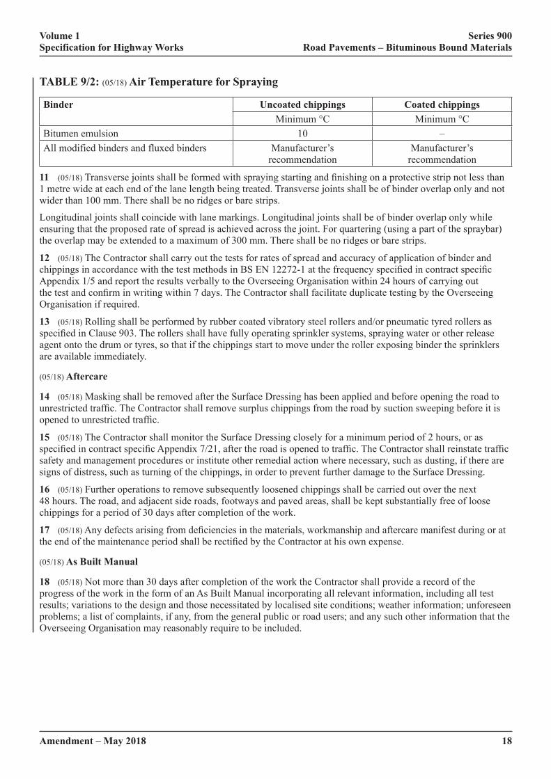
(iii) When the air temperature is at or below the values given in Table 9/2.
(iv) For emulsion binders when the relative humidity exceeds 80%.
(v) When the road surface temperature exceeds 35°C for roads carrying over 200 cv/lane/day or 40°C below that�traffic�level.
Volume 1 Series 900 Specification for Highway Works Road Pavements – Bituminous Bound Materials
18Amendment – May 2018
TABLE 9/2: (05/18) Air Temperature for Spraying
Binder Uncoated chippings Coated chippingsMinimum °C Minimum °C
Bitumen emulsion 10 –All modified binders and fluxed binders Manufacturer’s
recommendationManufacturer’s
recommendation
11 (05/18)�Transverse�joints�shall�be�formed�with�spraying�starting�and�finishing�on�a�protective�strip�not�less�than�1 metre wide at each end of the lane length being treated. Transverse joints shall be of binder overlap only and not wider than 100 mm. There shall be no ridges or bare strips.
Longitudinal joints shall coincide with lane markings. Longitudinal joints shall be of binder overlap only while ensuring that the proposed rate of spread is achieved across the joint. For quartering (using a part of the spraybar) the overlap may be extended to a maximum of 300 mm. There shall be no ridges or bare strips.
12 (05/18) The Contractor shall carry out the tests for rates of spread and accuracy of application of binder and chippings�in�accordance�with�the�test�methods�in�BS�EN�12272-1�at�the�frequency�specified�in�contract�specific�Appendix 1/5 and report the results verbally to the Overseeing Organisation within 24 hours of carrying out the�test�and�confirm�in�writing�within�7�days.�The�Contractor�shall�facilitate�duplicate�testing�by�the�Overseeing�Organisation if required.
13 (05/18) Rolling shall be performed by rubber coated vibratory steel rollers and/or pneumatic tyred rollers as specified�in�Clause�903.�The�rollers�shall�have�fully�operating�sprinkler�systems,�spraying�water�or�other�release�agent onto the drum or tyres, so that if the chippings start to move under the roller exposing binder the sprinklers are available immediately.
(05/18) Aftercare
14 (05/18) Masking shall be removed after the Surface Dressing has been applied and before opening the road to unrestricted�traffic.�The�Contractor�shall�remove�surplus�chippings�from�the�road�by�suction�sweeping�before�it�is�opened�to�unrestricted�traffic.
15 (05/18) The Contractor shall monitor the Surface Dressing closely for a minimum period of 2 hours, or as specified�in�contract�specific�Appendix�7/21,�after�the�road�is�opened�to�traffic.�The�Contractor�shall�reinstate�traffic�safety and management procedures or institute other remedial action where necessary, such as dusting, if there are signs of distress, such as turning of the chippings, in order to prevent further damage to the Surface Dressing.
16 (05/18) Further operations to remove subsequently loosened chippings shall be carried out over the next 48 hours. The road, and adjacent side roads, footways and paved areas, shall be kept substantially free of loose chippings for a period of 30 days after completion of the work.
17 (05/18)�Any�defects�arising�from�deficiencies�in�the�materials,�workmanship�and�aftercare�manifest�during�or�at�the�end�of�the�maintenance�period�shall�be�rectified�by�the�Contractor�at�his�own�expense.
(05/18) As Built Manual
18 (05/18) Not more than 30 days after completion of the work the Contractor shall provide a record of the progress of the work in the form of an As Built Manual incorporating all relevant information, including all test results; variations to the design and those necessitated by localised site conditions; weather information; unforeseen problems; a list of complaints, if any, from the general public or road users; and any such other information that the Overseeing Organisation may reasonably require to be included.
Volume 1 Series 900 Specification for Highway Works Road Pavements – Bituminous Bound Materials
Amendment – May 2018 19
920 (05/18) Bond Coats, Tack Coats and Other Bituminous Sprays
1 (05/18) Bond coats and tack coats used in conjunction with bituminous mixtures, other than those covered by Clause�942,�shall�be�in�accordance�with�this�Clause�and�the�requirements�specified�in�contract�specific�Appendix�7/1�and 7/4.
(05/18) Bond Coats
2 (05/18)�Bond�coats�for�bituminous�mixtures�shall�be�cationic�polymer�modified�bitumen�emulsions�complying�with�BS�EN�13808�or�polymer�modified�bitumen�complying�with�BS�EN�14023�with�a�minimum�peak�cohesion�value�of�1.0�J/cm2 when tested in accordance with BS EN 13588. They shall be CE marked and the Contractor shall submit the declaration of performance to the Overseeing Organisation prior to their application. The declaration of performance�shall�demonstrate�that�the�bond�coat�meets�the�requirements�of�the�specification.
(05/18) Tack Coats
3 (05/18)�Tack�coats�for�bituminous�mixtures�shall�be�unmodified�bitumen�emulsion�complying�with�BS EN 13808. They shall be CE marked and the Contractor shall submit the declaration of performance to the Overseeing Organisation prior to their application. The declaration of performance shall demonstrate that the tack coat�meets�the�requirements�of�the�specification.
(05/18) Bituminous Sprays
4 (05/18) Bituminous sprays used to facilitate sealing and curing shall consist of either bitumen emulsion complying with BS EN 13808 or paving grade bitumen complying with BS EN 12591. They shall be CE marked and the Contractor shall submit the declaration of performance to the Overseeing Organisation prior to their application. The declaration of performance shall demonstrate that the spray meets the requirements of the specification.
(05/18) Product Information
5 (05/18)�For�bond�coats,�tack�coats�and�bituminous�sprays�the�Contractor�shall�provide�the�information�specified�in�contract�specific�Appendix�7/4�and�supply�a�copy�to�the�Overseeing�Organisation�prior�to�the�application�of�the�product.
(05/18) Preparation
6 (05/18) The Contractor shall comply with any limitations on area availability and timing or other constraints for�the�work�as�specified�in�contract�specific�Appendix�1/13.�Before�spraying�is�commenced,�the�surface�shall�be�free�of�all�loose�material�and�standing�water�and�shall�comply�with�any�requirements�specified�in�contract�specific�Appendix�7/4.�When�specified�in�contract�specific�Appendix�7/4,�street�furniture,�ironwork�and�drop-kerbs�shall�be�masked using self-adhesive masking material before application starts and removed on completion of the works.
(05/18) Application
7 (05/18) Application shall be by metered mechanical spraying equipment, spray tanker or spraying device integral with the paving machine. The spraying equipment used shall not cause permanent deformation in the surface. For small or inaccessible areas, application may be by hand held sprayer with the agreement of the Overseeing Organisation.
8 (05/18) The target rates of spread of bond coats or tack coats below bituminous mixtures shall be in accordance with�BS�594987,�clause�5.5.�For�other�applications,�unmodified�bitumen�emulsions�shall�be�sprayed�at�the�rate�of�spread�specified�in�BS�434-2�or�as�stated�in�contract�specific�Appendix�7/4.
Volume 1 Series 900 Specification for Highway Works Road Pavements – Bituminous Bound Materials
20Amendment – May 2018
(05/18) Accuracy of Application
9 (05/18) Spray application shall be uniform. Before spraying begins, the Contractor shall provide the Overseeing Organisation�with�a�test�certificate�showing�the�results�for�rate�of�spread�and�accuracy�of�spread.�These�tests�shall�be carried out in accordance with BS EN 12272-1 by an appropriate organisation, accredited in accordance with sub-Clause�105.4�for�those�tests.�The�certificate�shall�demonstrate�that�the�spraying�device�has�been�tested,�using�the product to be used in the contract, not more than six weeks before commencement of the work. The tolerance on�the�specified�rate�of�spread�shall�not�exceed�±20%�and�the�coefficient�of�variation�of�the�transverse�distribution�shall not exceed 15%. During the works the Contractor shall repeat the tests for rate of spread and accuracy of application�at�the�frequency�specified�in�contract�specific�Appendix�1/5.�The�results�shall�be�reported�verbally�to�the�Overseeing Organisation within 24 hours of carrying out a test and in writing within 7 days. Where application is by hand held sprayer, the rate of spread shall be measured by calculating the volume applied per square metre and evenness shall be visually assessed.
(05/18) Joints
10 (05/18) There shall be no bare strips or areas having less than the minimum permitted rate of spread. Transverse joints shall have an overlap not wider than 300 mm. Longitudinal joints shall have an overlap to ensure that the minimum permitted rate of spread is achieved across the joint. For quartering (using part of the spraybar) the longitudinal joint overlap width may be extended to a maximum of 300 mm. Paver integral sprayers shall provide a wet edge to ensure spray overlap under adjacent overlays such that the minimum permitted rate of spread is achieved across the longitudinal joint. Where the longitudinal spray overlap causes the effective rate of spread to be increased�by�more�than�50%�of�the�specified�rate,�then�the�width�of�overlap�shall�not�be�greater�than�100�mm�and�shall be outside the location of the wheel tracks for the lane.
(05/18) Overlaying Concrete Surfaces
11 (05/18) The Contractor shall submit evidence of the suitability of the bond or tack coats he intends to use when overlaying concrete surfaces to the Overseeing Organisation prior to the commencement of the work.
(05/18) Blinding Material for Bituminous Sprays
12 (05/18)�When�specified�in�contract�specific�Appendix�7/4,�blinding�material�shall�consist�of�hard�clean�crushed�fine�aggregate�or�slag�fine�aggregate�or�sand�containing�not�more�than�15%�by�mass�retained�on�a�6.3�mm�sieve.�It�shall be distributed over the sprayed area and left. Blinding used on cementitious materials shall be light in colour to minimise solar gain. All loose material on a sprayed surface including non-adhered blinding material shall be removed prior to the application of an overlay.
(05/18) Chipping to Prevent Binder Pickup
13 (05/18) When chippings are used to prevent tack or bond coat pickup on vehicle tyres, they shall consist of hard, clean aggregate 2/4 mm or 2/6 mm Gc 85/35. The rate of application of aggregate shall be the minimum necessary and shall be distributed by metered mechanical means. Bond coat shall be visible after aggregate application to ensure bond is still achieved between the pavement layers.
921 (05/18) Surface Macrotexture of Bituminous Surface Courses
1 (05/18) Surface macrotexture of bituminous surface courses other than those covered by Clause 942, shall be in�accordance�with�this�Clause�where�unless�otherwise�specified�in�contract�specific�Appendix�7/1.�Initial�surface�macrotexture for bituminous surface courses shall be measured using the volumetric patch method described in BS EN 13036-1.
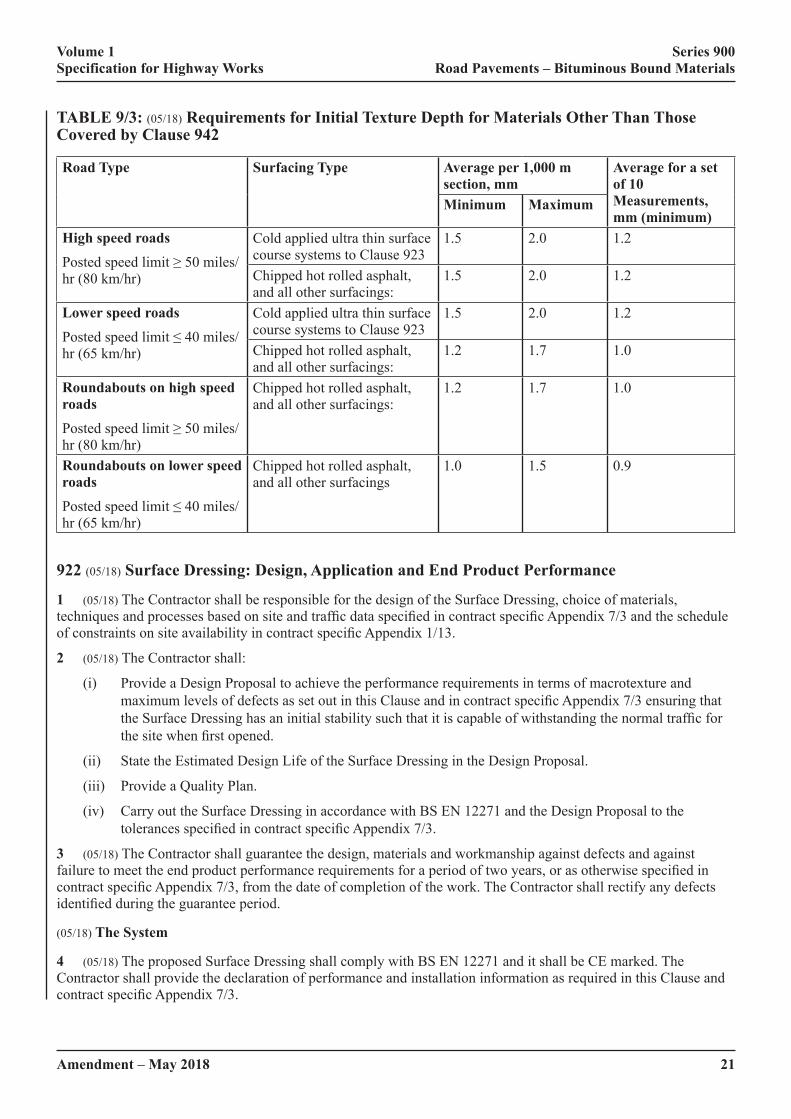
2 (05/18) Texture depth shall be measured by 10 individual measurements taken at approximately 5 m spacing along�a�diagonal�line�across�the�lane�width.�Unless�otherwise�specified�in�contract�specific�Appendix�7/1,�at�least�one set of 10 measurements shall be made for each 250 m section of carriageway lane. The average texture depth for each set of 10 individual measurements and the average texture depth of each 1,000 m section (or complete carriageway lane where this is less than 1,000 m) shall not be less than the appropriate values shown in Table 9/3, unless�otherwise�specified�in�contract�specific�Appendix�7/1.
Volume 1 Series 900 Specification for Highway Works Road Pavements – Bituminous Bound Materials
Amendment – May 2018 21
TABLE 9/3: (05/18) Requirements for Initial Texture Depth for Materials Other Than Those Covered by Clause 942
Road Type Surfacing Type Average per 1,000 m section, mm
Average for a set of 10 Measurements, mm (minimum)
Minimum Maximum
High speed roadsPosted�speed�limit�≥�50�miles/hr (80 km/hr)
Cold applied ultra thin surface course systems to Clause 923
1.5 2.0 1.2
Chipped hot rolled asphalt, and all other surfacings:
1.5 2.0 1.2
Lower speed roadsPosted�speed�limit�≤�40�miles/hr (65 km/hr)
Cold applied ultra thin surface course systems to Clause 923
1.5 2.0 1.2
Chipped hot rolled asphalt, and all other surfacings:
1.2 1.7 1.0
Roundabouts on high speed roadsPosted�speed�limit�≥�50�miles/hr (80 km/hr)
Chipped hot rolled asphalt, and all other surfacings:
1.2 1.7 1.0
Roundabouts on lower speed roadsPosted�speed�limit�≤�40�miles/hr (65 km/hr)
Chipped hot rolled asphalt, and all other surfacings
1.0 1.5 0.9
922 (05/18) Surface Dressing: Design, Application and End Product Performance
1 (05/18) The Contractor shall be responsible for the design of the Surface Dressing, choice of materials, techniques�and�processes�based�on�site�and�traffic�data�specified�in�contract�specific�Appendix�7/3�and�the�schedule�of�constraints�on�site�availability�in�contract�specific�Appendix�1/13.
2 (05/18) The Contractor shall:
(i) Provide a Design Proposal to achieve the performance requirements in terms of macrotexture and maximum�levels�of�defects�as�set�out�in�this�Clause�and�in�contract�specific�Appendix�7/3�ensuring�that�the�Surface�Dressing�has�an�initial�stability�such�that�it�is�capable�of�withstanding�the�normal�traffic�for�the�site�when�first�opened.
(ii) State the Estimated Design Life of the Surface Dressing in the Design Proposal.
(iii) Provide a Quality Plan.
(iv) Carry out the Surface Dressing in accordance with BS EN 12271 and the Design Proposal to the tolerances�specified�in�contract�specific�Appendix�7/3.
3 (05/18) The Contractor shall guarantee the design, materials and workmanship against defects and against failure�to�meet�the�end�product�performance�requirements�for�a�period�of�two�years,�or�as�otherwise�specified�in�contract�specific�Appendix�7/3,�from�the�date�of�completion�of�the�work.�The�Contractor�shall�rectify�any�defects�identified�during�the�guarantee�period.
(05/18) The System
4 (05/18) The proposed Surface Dressing shall comply with BS EN 12271 and it shall be CE marked. The Contractor shall provide the declaration of performance and installation information as required in this Clause and contract�specific�Appendix�7/3.

Volume 1 Series 900 Specification for Highway Works Road Pavements – Bituminous Bound Materials
22Amendment – May 2018
The�declaration�of�performance�shall�demonstrate�that�the�system�meets�the�requirements�of�the�specification�and�provides�performance�categories�for�all�of�the�items�identified�in�this�Clause�and�contract�specific�Appendix�7/3.
(05/18) Materials and Equipment – Binder
5 (05/18) The binder shall be bitumen emulsion complying with BS EN 13808 and be CE marked and comply with�requirements�stated�in�contract�specific�Appendix�7/3.
6 (05/18) The Contractor shall provide, with his Design Proposal, the declaration of performance for the binder which�shall�demonstrate�that�the�binder�shall�meet�the�requirements�of�the�specification�including�the�properties�detailed�in�contract�specific�Appendix�7/3.
Contract�compliance�testing�shall�be�carried�out�as�detailed�in�contract�specific�Appendix�1/5.�The�recovery�of�the�binder shall be carried out in accordance with Clause 955. The test to determine Vialit Pendulum Cohesion shall be�carried�out�in�accordance�with�BS�EN�13588.�The�Contractor�shall�provide�rheological�product�identification�data�for�modified�binders�in�accordance�with�BS�EN�14770.�The�data�provided�shall�be�not�more�than�6�months�old�and obtained on samples of binder representative of binder manufactured and supplied using the same source and processes as the proposed binder. Health and Safety information and a safe handling guide from the manufacturer shall be provided together with details of any weather restrictions placed upon use of the binder.
7 (05/18)�The�binder�application�shall�be�uniform�and�for�motorways,�trunk�roads�and�heavily�trafficked�and�highly�stressed�roads,�shall�be�of�sufficient�width�to�allow�a�full�lane�to�be�dressed�in�a�single�pass.�Before�spraying�begins,�the�Contractor�shall�provide�the�Overseeing�Organisation�with�a�test�certificate�showing�test�results�for�rate of spread and accuracy of spread of binder carried out in accordance with the test methods in BS EN 12272- 1 and issued by, an appropriate organisation, accredited in accordance with sub-Clause 105.4 for those tests, demonstrating that the binder sprayer has been tested, using the binder to be used in the Contract, not more than six weeks before the commencement of the work, and that it complies with the requirements set out in contract specific�Appendix�7/3.
(05/18) Materials and Equipment – Chippings
8 (05/18) The chippings shall be crushed rock, slag, gravel or calcined bauxite complying with the general requirements of BS EN 13043:2002. The aggregate shall have a minimum declared PSV and a maximum AAV as specified�in�contract�specific�Appendix�7/3.
9 (05/18)�Chipping�spreaders�shall�have�controlled�metering�and�be�capable�of�variable�or�fixed�width�application�to match the binder sprayer. Before a spreader is used, the Contractor shall provide the Overseeing Organisation with�a�test�certificate�showing�test�results�for�rate�of�spread�and�accuracy�of�spread�of�chippings�carried�out�in�accordance with the test methods in BS EN 12272-1, and issued by an appropriate organisation, accredited in accordance with sub-Clause 105.4 for those tests, demonstrating that the chipping spreader has been tested, using chippings similar to those to be used in the Contract, not more than six weeks before the commencement of the work,�and�that�it�complies�with�the�requirements�set�out�in�contract�specific�Appendix�7/3.
(05/18) Preparation
10 (05/18) Any necessary remedial works to the road surface and structure shall be completed prior to or as part of the contract and agreed as acceptable by the Overseeing Organisation and the Contractor before Surface Dressing commences.
11 (05/18) Before binder is applied, street furniture shall be masked using self-adhesive masking material. Oil, sand or similar materials shall not be used. Any packed mud or other deposits on the road surface shall be removed, and the road surface shall be swept free of all loose material.
(05/18) Traffic Safety and Management
12 (05/18)�Traffic�Safety�and�Management�shall�be�in�accordance�with�the�requirements�of�Series�100�and�the�site�specific�requirements�specified�in�contract�Appendix�1/17�and�the�constraints�described�in�contract�specific�Appendix 1/13.
Volume 1 Series 900 Specification for Highway Works Road Pavements – Bituminous Bound Materials
Amendment – May 2018 23
(05/18) Application
13 (05/18)�Restrictions�to�be�observed�in�the�event�of�adverse�weather�shall�be�as�specified�in�contract�specific�Appendix�7/3.�Transverse�joints�shall�be�formed�with�spraying�starting�and�finishing�on�a�protective�strip�not�less�than 1 metre wide at each end of the lane length being treated. Transverse joints shall be of binder overlap only and not wider than 100 mm. There shall be no ridges or bare strips. Longitudinal joints shall coincide with lane markings. Longitudinal joints shall be of binder overlap only, while ensuring that the proposed rate of spread is achieved across the joint, for quartering (using a part of the spraybar) the overlap may be extended to a maximum of 300 mm. There shall be no ridges or bare strips.
14 (05/18) The Contractor shall carry out the tests for rates of spread and accuracy of application of binder and chippings�in�accordance�with�the�test�methods�in�BS�EN�12272-1�at�the�frequency�specified�in�contract�specific�Appendix 1/5 and report the results verbally to the Overseeing Organisation within twenty-four hours of carrying out�the�test�and�confirm�in�writing�within�seven�days.�The�Contractor�shall�facilitate�duplicate�testing�by�the�Overseeing Organisation if required.
(05/18) Aftercare
15 (05/18) Masking shall be removed after the Surface Dressing has been applied and before opening the road to unrestricted�traffic.�The�time�period�before�unrestricted�traffic�may�use�the�Surface�Dressing�shall�not�exceed�that�specified�in�contract�specific�Appendix�7/3.�The�Contractor�shall�remove�surplus�chippings�from�the�road�by�suction�sweeping�before�it�is�opened�to�unrestricted�traffic.
16 (05/18) The Contractor shall monitor the Surface Dressing closely for a minimum period of 2 hours, or as specified�in�contract�specific�Appendix�7/3,�after�the�road�is�opened�to�traffic.�The�Contractor�shall�reinstate�traffic�safety and management procedures or institute other such remedial action where necessary, such as dusting, if there are signs of distress, such as turning of the chippings, in order to prevent further damage to the Surface Dressing.
17 (05/18) Further operations to remove subsequently loosened chippings shall be carried out over the next 48 hours. The road, and adjacent side roads, footways and paved areas, shall be kept substantially free of loose chippings for a period of 30 days after completion of the work.
(05/18) As Built Manual
18 (05/18) Not more than 30 days after completion of the work the Contractor shall provide a record of the progress of the work in the form of an As Built Manual incorporating all relevant information, including: all contract compliance test results; variations to the Design Proposal and those necessitated by localised site conditions; a record�of�traffic�control�carried�out;�weather�information;�unforeseen�problems;�a�list�of�complaints,�if�any,�from�the�general public or road users; and any other information that the Overseeing Organisation may reasonably require to be included.
(05/18) Performance Standards During the Guarantee Period
(05/18) Surface Macrotexture
19 (05/18) The Contractor is responsible for maintaining the surface macrotexture requirements set out in contract specific�Appendix�7/3�throughout�the�guarantee�period.
The�definitive�test�is�the�volumetric�patch�technique�measured�in�accordance�with�BS�EN�13036-1�except�that�10�individual�measurements�shall�be�made�on�the�nearside�(inside)�wheel-track�of�the�most�heavily�trafficked�lane. The average macrotexture depth of each lane kilometre, or the complete carriageway lane where this is less than�1,000�metres,�shall�be�as�specified�in�contract�specific�Appendix�7/3.�The�average�of�each�set�of�10�individual�measurements shall be not less than 80% of the minimum permitted.
The�Overseeing�Organisation�will�use�the�TRAffic-speed�Condition�Survey�(TRACS)�or�other�suitable�equipment�to determine the Sensor Measured Texture Depth (SMTD) for trunk roads including motorways and other highly trafficked�or�highly�stressed�roads.�Measurements�of�SMTD�shall�be�made�in�the�nearside�and�offside�wheel-tracks�of all lanes. For other roads where road closure is less critical the volumetric patch technique or other measuring device such as the Mini Texture Meter may be used.

Volume 1 Series 900 Specification for Highway Works Road Pavements – Bituminous Bound Materials
24Amendment – May 2018
The SMTD or results from other devices shall be calibrated for the particular Surface Dressing product design and condition against volumetric patch values to provide the Volumetric Patch Equivalent value. The macrotexture depths will be measured after 11 months and before 13 months and additionally for two year guarantee period contracts�after�22�months�and�before�24�months�unless�otherwise�specified�in�contract�specific�Appendix�7/3.�When�required, the Contractor shall design the Surface Dressing to limit the maximum macrotexture after four weeks trafficking�to�that�specified�in�contract�specific�Appendix�7/3�and�the�macrotexture�depths�will�be�measured,�for�this�purpose,�between�three�weeks�and�five�weeks�after�completion�of�the�Works.
(05/18) Defects
20 (05/18) The extent of chipping loss or other defects will be monitored using a visual method of assessment. The performance standard is that any section of the works shall be deemed as having failed if the areas of defects do not comply�with�the�classes�specified�in�contract�specific�Appendix�7/3.�If�there�is�a�failed�section,�the�Contractor�shall�agree remedial measures with the Overseeing Organisation and undertake the remedial measures.
In the event that the Contractor and Overseeing Organisation are unable to reach agreement on whether a section has failed by qualitative visual assessment described in BS EN 12272-2, the level of defects shall be determined in accordance with the quantitative test methods in BS EN 12272-2. Any section failing to meet the required standard as�specified�in�contract�specific�Appendix�7/3�shall�be�subject�to�remedial�action�by�the�Contractor�after�agreement�of the Overseeing Organisation.
923 (05/18) Cold Applied Ultra Thin Surfacing
(05/18) General
1 (05/18) The Cold Applied Ultra Thin Surfacing shall meet the product performance requirements under the combinations�of�traffic�level�and�site�classification�specified�in�contract�specific�Appendix�7/1�and�it�shall�meet�the�following criteria.
(i) Where the product falls under the scope of a harmonised European standard under the Construction Products Regulation the Cold Applied Ultra Thin Surfacing shall have a declaration of performance and be CE marked in accordance with the relevant British adopted European standard.
(ii) Where the product does not fall under the scope of a harmonised European standard under the Construction Products Regulation it shall either:
(a) have a declaration of performance and be CE marked in accordance with a European Technical Assessment; or
(b)� �be�certified�under�a�product�acceptance�scheme�as�detailed�in�sub-Clauses�104.15�and�104.16�such�as�HAPAS�certification.
The�Contractor�shall�supply�the�certification�or�declaration�of�performance�to�the�Overseeing�Organisation,�it�shall�demonstrate�that�the�Cold�Applied�Ultra�Thin�Surfacing�shall�meet�the�requirements�of�the�specification.
The�installation�of�the�surfacing�shall�be�certified�under�a�product�acceptance�scheme�as�detailed�in�sub-Clauses�104.15�and�104.16�such�as�HAPAS�certification.
2 (05/18) Cold Applied Ultra Thin Surfacing systems that are supplied in accordance with sub-Clause 1 paragraph (ii) (b) shall be produced and installed by organisations that are registered to the National Highways Sector Scheme 13 for The Supply and Application of Surface Treatments to Road Surfaces, as listed in Appendix A.
(05/18) Documentation, Test Certificates and Material Samples
3 (05/18) The Contractor shall supply a Quality Plan and Installation Method Statement to the Overseeing Organisation.
4 (05/18)�Test�certificates�stating�the�properties�of�the�aggregate�to�be�used�shall�be�supplied�to�the�Overseeing�Organisation unless the values are declared in the Declaration of Performance under the CE mark.

Volume 1 Series 900 Specification for Highway Works Road Pavements – Bituminous Bound Materials
Amendment – May 2018 25
5 (05/18) The details of the component materials and their relative proportions and/or spread rates for use in the permanent�works�shall�be�notified�to�the�Overseeing�Organisation.�The�component�materials�listed�shall�include,�as�appropriate,�coarse�aggregates,�fine�aggregates,�filler,�additives�(including�fibres),�binder,�modifier�and�bond�coat,�and shall be subdivided into layers if applied.
6 (05/18)�When�required�in�contract�specific�Appendix�1/6,�samples�of�aggregate,�bond�coat�or�binder,�modified�or�unmodified�bitumen�from�either�the�spray�bar�or�storage�tank�or�mixed�bituminous�materials�from�the�pavement�surface or other suitable sampling point shall be supplied to the Overseeing Organisation.
(05/18) Aggregates
7 (05/18) Coarse aggregate shall be crushed rock or steel slag complying with Clause 901 when tested in accordance with the procedures of BS EN 13043:2002. The coarse aggregate shall additionally have the following properties.
(i)� Polished�Stone�Value�(PSV)�–�as�specified�in�contract�specific�Appendix�7/1�–�BS�EN�13043:2002;
(ii)� Aggregate�Abrasion�Value�(AAV)�–�as�specified�in�contract�specific�Appendix�7/1�–�BS�EN�13043:2002;
(iii)� Los�Angeles�Coefficient�(LA)�–�not�greater�than�LA30. – BS EN 13043:2002;
(iv) Flakiness Index (FI) – not more than FI20. – BS EN 13043:2002.
(05/18) Performance Levels
8 (05/18)�Cold�Applied�Ultra�Thin�Surfacing�is�permitted�on�Site�Categories�B,�C,�D,�E,�F�and�G�as�defined�in�Table 9/4.
TABLE 9/4: (05/18) Site Stress Level Classification
Site Category Site Definition Stress LevelA Motorway (main line) 1B Dual carriageway (all purpose) non-event sections 1C Single carriageway non-event sections 1D Dual carriageway (all purpose) minor junctions 1E Single carriageway minor junctions 1F Approaches to and across major junctions (all limbs) 2G Gradient >5%, longer than 50 m (Dual downhill; single uphill
and downhill)2
H1 Bend (not subject to 40 mph or lower speed limit) radius 100 – 250 m
2
H2 Bend (not subject to 40 mph or lower speed limit) radius <100 m 3L Roundabout 3J Approach to roundabout 4K Approach to traffic signals, pedestrian crossing, railway level
crossing and similar4
9 (05/18)�The�road/tyre�noise�level�of�the�cold�applied�ultra�thin�surface�shall�be�as�specified�in�contract�specific�Appendix�7/1,�as�defined�in�Table�9/5.
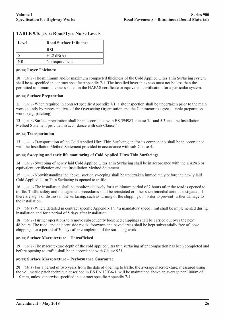
Volume 1 Series 900 Specification for Highway Works Road Pavements – Bituminous Bound Materials
26Amendment – May 2018
TABLE 9/5: (05/18) Road/Tyre Noise Levels
Level Road Surface InfluenceRSI
0 +1.2 dB(A)NR No requirement
(05/18) Layer Thickness
10 (05/18) The minimum and/or maximum compacted thickness of the Cold Applied Ultra Thin Surfacing system shall�be�as�specified�in�contract�specific�Appendix�7/1.�The�installed�layer�thickness�must�not�be�less�than�the�permitted�minimum�thickness�stated�in�the�HAPAS�certificate�or�equivalent�certification�for�a�particular�system.
(05/18) Surface Preparation
11 (05/18)�When�required�in�contract�specific�Appendix�7/1,�a�site�inspection�shall�be�undertaken�prior�to�the�main�works jointly by representatives of the Overseeing Organisation and the Contractor to agree suitable preparation works (e.g. patching).
12 (05/18) Surface preparation shall be in accordance with BS 594987, clause 5.1 and 5.3, and the Installation Method Statement provided in accordance with sub-Clause 4.
(05/18) Transportation
13 (05/18) Transportation of the Cold Applied Ultra Thin Surfacing and/or its components shall be in accordance with the Installation Method Statement provided in accordance with sub-Clause 4.
(05/18) Sweeping and early life monitoring of Cold Applied Ultra Thin Surfacings
14 (05/18) Sweeping of newly laid Cold Applied Ultra Thin Surfacing shall be in accordance with the HAPAS or equivalent�certification�and�the�Installation�Method�Statement.
15 (05/18) Notwithstanding the above, suction sweeping shall be undertaken immediately before the newly laid Cold�Applied�Ultra�Thin�Surfacing�is�opened�to�traffic.
16 (05/18) The installation shall be monitored closely for a minimum period of 2 hours after the road is opened to traffic.�Traffic�safety�and�management�procedures�shall�be�reinstated�or�other�such�remedial�actions�instigated,�if�there are signs of distress in the surfacing, such as turning of the chippings, in order to prevent further damage to the installation.
17 (05/18)�Where�detailed�in�contract�specific�Appendix�1/17�a�mandatory�speed�limit�shall�be�implemented�during�installation and for a period of 5 days after installation.
18 (05/18) Further operations to remove subsequently loosened chippings shall be carried out over the next 48 hours. The road, and adjacent side roads, footways and paved areas shall be kept substantially free of loose chippings for a period of 30 days after completion of the surfacing work.
(05/18) Surface Macrotexture – Untrafficked
19 (05/18) The macrotexture depth of the cold applied ultra thin surfacing after compaction has been completed and before�opening�to�traffic�shall�be�in�accordance�with�Clause�921.
(05/18) Surface Macrotexture – Performance Guarantee
20 (05/18)�For�a�period�of�two�years�from�the�date�of�opening�to�traffic�the�average�macrotexture,�measured�using�the volumetric patch technique described in BS EN 13036-1, will be maintained above an average per 1000m of 1.0�mm,�unless�otherwise�specified�in�contract�specific�Appendix�7/1.

Volume 1 Series 900 Specification for Highway Works Road Pavements – Bituminous Bound Materials
Amendment – May 2018 27
21 (05/18) Where measurement is necessary to demonstrate compliance during the guarantee period, the macrotexture�shall�be�measured�in�accordance�with�BS�EN�13036-1�in�the�most�heavily�trafficked�lane�at�10�m�intervals. The average value of a set of 10 individual measurements taken along the centre of the most heavily worn wheel-track�shall�not�be�less�than�the�appropriate�value�stated�in�contract�specific�Appendix�7/1.
(05/18) Surfacing Integrity – Performance Guarantee
22 (05/18)�Unless�otherwise�stated�in�contract�specific�Appendix�7/1�a�guarantee�shall�be�provided�for�the�integrity�of�the�surfacing�and�the�workmanship�for�a�period�of�five�years�from�the�date�of�opening�to�traffic.
23 (05/18)�The�five-year�guarantee�shall�include�for�defects�such�as�fretting,�ravelling,�stripping�and�loss�of�chippings. Replacement of the surfacing or other remedial measures agreed with the Overseeing Organisation shall be�executed�if�the�surfacing�is�in�a�“Suspect”,�“Poor”�or�“Bad”�condition�as�defined�in�Appendix�A�of�TRL�Report�TRL674 – “Durability of thin surfacing systems, Part 4, Final report after nine years monitoring, TRL report 674”.
924 (05/18) High Friction Surfaces
1 (05/18)�High�friction�surfacing�systems�shall�have�current�HAPAS�certificate�or�equivalent�product�acceptance�scheme�certification�as�described�in�sub-Clauses�104.15�and�104.16.
2 (05/18) High friction surfacing shall be installed in accordance with the requirements of the HAPAS or equivalent�product�acceptance�scheme�certification.
3 (05/18)�The�high�friction�surfacing�system�HAPAS�or�equivalent�product�acceptance�scheme�certification�Type�Classification�required�for�each�location�shall�be�as�specified�in�contract�specific�Appendix�7/1.
(05/18) Aggregate
4 (05/18) Aggregate used in high friction surfacing systems shall have the minimum declared PSV category specified�in�contract�specific�Appendix�7/1�in�accordance�with�BS�EN�13043:2002,�clause�4.2.3.�The�resistance�to�abrasion�of�coarse�aggregate�shall�have�the�maximum�AAV�specified�in�contract�specific�Appendix�7/1�in�accordance with BS EN 13043:2002, clause 4.2.4. The Contractor shall provide, before work commences, the declaration of performance for the aggregate to the Overseeing Organisation. The declaration of performance shall demonstrate�that�the�aggregate�shall�meet�the�requirements�of�the�specification.
(05/18) Installation and Quality Control Procedures
5 (05/18) The installation and quality control procedures shall be in accordance with the HAPAS or equivalent product�acceptance�scheme�certification�for�each�system�and�the�current�method�statement.�The�results�of�all�quality�control checks carried out on site by the Contractor and quality management information compiled in accordance with�the�requirements�of�the�Certificate,�including�results�from�surveillance�visits,�shall�be�made�available�to�the�Overseeing Organisation on request.
(05/18) System Coverage
6 (05/18) For each location where high friction surfacing is applied, the total quantities of each system component used, the measured area of the surface treated and the calculated coverage rate in kg/m2 shall be reported to the Overseeing Organisation within three days of completion at that location. For systems in which aggregate is broadcast�over�a�film�of�binder�applied�to�the�surface,�the�calculated�coverage�rate�shall�be�that�of�the�binder�film�and shall not include the mass of the aggregate.
(05/18) Guarantee
7 (05/18) The Contractor shall guarantee the high friction surfacing materials and workmanship for a period of two�years�from�the�date�of�opening�the�surfacing�to�traffic.�This�guarantee�shall�cover�failure�to�meet�the�minimum�requirements�set�out�in�Table�4�of�the�HAPAS�document�‘Guideline�Document�for�the�Assessment�and�Certification�of High Friction Surfaces for Highways’.
Volume 1 Series 900 Specification for Highway Works Road Pavements – Bituminous Bound Materials
28Amendment – May 2018
925 (05/18) Testing of Bituminous Mixtures
1 (05/18) The contract compliance sampling and testing of bituminous mixtures shall comply with BS EN 12697, except�where�otherwise�specified�in�this�Series.
2 (05/18)�Additional�testing�shall�be�carried�out�as�specified�in�contract�specific�Appendices�7/1,�1/5�and�1/6.
926 (05/18) In Situ Recycling: The Repave Process
1 (05/18) Where milling is required, it shall be carried out in accordance with Clause 709, and as described in contract�specific�Appendix�7/5.
(05/18) Heating and Scarifying
2 (05/18) Surfaces to be treated shall be heated by plant with heating surfaces insulated and fully enclosed. The heated-width�of�surfacing�shall�exceed�the�scarified�width�by�at�least�75�mm�on�each�side,�except�against�the�edge�of the carriageway or kerb face. When new surfacing material is spilt onto the road surface it shall be removed before�the�existing�surface�is�heated�and�scarified.�Areas�of�unscarified�material�shall�not�exceed�50�mm�x�50�mm.
3 (05/18)�The�depth�of�scarification�shall�be�such�that�the�bottom�of�the�scarified�layer�is�parallel�to�and�below�the�finished�road�surface�level�by�the�thickness�of�surface�course�material�specified�in�contract�specific�Appendix�7/5.�A�tolerance�of�±�6�mm�is�permissible.
4 (05/18) Where ironwork and other obstructions occur, these shall be suitably protected or removed and the void covered. Surface dressings and large areas of road markings shall be removed by milling, planing, scarifying or similar.
5 (05/18)�The�heated�surface�shall�be�evenly�scarified�to�comply�with�the�requirements�of�sub-Clause�3�of�this�Clause.�When�ironwork�is�left�in�place�or�raised,�the�adjacent�areas�shall�be�scarified�by�other�means,�with�the�material either left in place or removed, prior to passage of the machine. If ironwork needs to be re-levelled, on completion of work, the new surface course material shall be used to make good the road surface for a maximum width of 200 mm around the ironwork.
6 (05/18) During the reheating process the surface temperature of the road shall not exceed 200°C for more than 5 minutes.
(05/18) New Surfacing
7 (05/18)�New�surface�course�shall�conform�to�Clauses�910,�911,�923,�942�or�943,�as�described�in�contract�specific�Appendix 7/5.
8 (05/18)�The�new�surfacing�material�shall�be�laid�on,�and�compacted�with�the�re-profiled�surfacing,�which�shall�be at a temperature within the range of 70°C to 150°C.
927 & 928 (05/18) Not Used
929 (05/18) Dense Base and Binder Course Asphalt Concrete (Design Mixtures)
1 (05/18) Designed dense base and binder course asphalt concrete (formerly macadams), including HDM and HMB, shall be asphalt concrete conforming to BS EN 13108-1, the example of BSI PD 6691 Annex B for the selected�mixture,�and�requirements�specified�in�contract�specific�Appendix�7/1.�The�mixture�designation�shall�be�one of the following:
(i) AC 32 HDM base 40/60 des.
(ii) AC 32 dense base 40/60 des.
(iii) AC 32 HMB base 30/45 des.

Volume 1 Series 900 Specification for Highway Works Road Pavements – Bituminous Bound Materials
Amendment – May 2018 29
(iv) AC 20 HDM bin 40/60 des.
(v) AC 32 HDM bin 40/60 des.
(vi) AC 20 dense bin 40/60 des.
(vii) AC 32 dense bin 40/60 des.
(viii) AC 20 HMB bin 30/45 des.
(ix) AC 32 HMB bin 30/45 des.
2 (05/18) The volumetric properties of mixtures shall follow the example in BSI PD 6691, clause B.3.2 for designed base mixtures and BSI PD 6691, clause B.3.3 for designed binder course mixtures.
3 (05/18)�When�specified�in�contract�specific�Appendix�7/1,�the�volumetric�properties�of�the�mixture�shall�be�monitored by determining the void content of cores compacted to refusal. Core pairs and samples of loose mix shall be taken every 500 lane metres and tested in accordance with BS 594987, clauses C.2.1, C.2.2, C.3, C.4.1 and C.4.2. If the mean air void content at refusal of any three consecutive pairs of cores falls below 0.5%, the mixture target composition shall be reviewed and the type test revalidated in accordance with BS 594987, Annex C.
(05/18) Deformation Resistance
4 (05/18) The resistance to permanent deformation of the mixture shall be in accordance with the appropriate class selected�from�Table�D.2�of�PD�6691,�as�specified�in�contract�specific�Appendix�7/1.
5 (05/18)�When�specified�in�contract�specific�Appendix�7/1,�the�resistance�to�permanent�deformation�of�material�laid in the permanent works shall be monitored by testing in accordance with clauses D 3.1, 3.2 and 3.3 of BS�594987�Annex�D.�Six�cores�shall�be�taken�from�the�first�kilometre�length�of�material�from�each�mixing�plant�and thereafter one further core from each subsequent lane kilometre. Results shall be assessed on successive rolling means�of�sets�of�six�consecutive�results�and�shall�be�deemed�to�conform�if�the�mean�is�no�greater�than�the�specified�value�and�individual�values�not�more�than�50%�greater�than�the�specified�value.
(05/18) Stiffness
6 (05/18) Stiffness of the mixture shall be assessed in accordance with BS 594987, Annex E.
Mixtures with 40/60 grade binder shall conform to category Smin 1800�as�defined�in�BS�EN�13108-1,�clause�5.4.2.
Mixtures with 30/45 grade binder shall conform to category Smin 2800�as�defined�in�BS�EN�13108-1,�clause�5.4.2.
(05/18) Compaction Control for the Permanent Works
7 (05/18) Compaction shall be controlled and monitored in accordance with the general requirements of BS�594987�9.5.1�and�the�specific�requirements�of�this�Clause.
8 (05/18) Compaction shall be continuously assessed using an indirect density gauge in accordance with BS 594987 9.4.2 with readings taken at 20 m intervals in alternate wheel-tracks. Gauge readings shall also be taken�at�each�core�location�specified�in�sub-Clauses�12�and�14.�Each�gauge�shall�be�individually�calibrated�on�each�mixture from each mixing plant and the calibrations shall be continually checked and updated based on correlations between gauge readings and core densities at the same locations.
9 (05/18) For each location, the in situ void content shall be determined in accordance with BS EN 12697-8 using the bulk density from the gauge reading and a maximum density taken from the mixture type testing data and updated with values from testing in accordance with sub-Clause 12.
10 (05/18) The average in situ void content calculated from any six consecutive indirect gauge readings shall not exceed 7%.
11 (05/18) In the event of a failure to meet the requirements in sub-Clause 10, cores shall be taken at each location and void contents determined as described in sub-Clause 12 and the evaluation of the extent of any non-conformity shall be based on these. If it is necessary to remove and replace any material to restore conformity this shall be in lengths not less than 15 m unless otherwise agreed by the Overseeing Organisation.

Volume 1 Series 900 Specification for Highway Works Road Pavements – Bituminous Bound Materials
30Amendment – May 2018
12 (05/18) For the material from each mixing plant, a pair of cores shall be taken from every 1,000 linear metres laid and the void content shall be determined in accordance with BS 594987, clause 9.5.1.3.
13 (05/18) The average in situ air voids for each core pair shall not exceed 7%.
14 (05/18) For the material from each mixing plant a pair of cores shall be taken every 250 linear metres laid, centred�100�mm�from�the�final�joint�position�at�any�unsupported�edge�and�the�air�void�shall�be�determined�in�accordance with BS 594987, clause 9.5.1.3.
15 (05/18) The average in situ void content for each of these pairs shall not exceed 9%.
16 (05/18) In the event of non-conformity with sub-Clauses 13 or 15 then density readings with indirect gauges and, if necessary, further cores shall be taken to establish the extent. If it is necessary to remove and replace any material to restore conformity, this shall be in lengths not less than 15 m unless otherwise agreed by the Overseeing Organisation.
17 (05/18) Each core extracted shall be examined for evidence of excessive voids below the depth to which the indirect density gauge penetrates. If excessive voids are observed, further cores shall be taken to determine its extent.
18 (05/18)�Two�copies�of�the�final�indirect�density�test�results�obtained�and�their�correlation�with�in�situ�air�void�contents shall be passed to the Overseeing Organisation within 72 hours.
930 (05/18) EME2 Base and Binder Course Asphalt Concrete
1 (05/18) EME2 base and binder course asphalt concrete shall conform to BS EN 13108-1, the example in BSI�PD�6691�Annex�B�for�the�selected�mixture,�the�requirements�of�this�Clause�and�those�specified�in�contract�specific�Appendix�7/1.�The�mixture�designation�shall�be�one�of�the�following:
(i) AC 10 EME2 bin/base 10/20 des.
(ii) AC 10 EME2 bin/base 15/25 des.
(iii) AC 14 EME2 bin/base 10/20 des.
(iv) AC 14 EME2 bin/base 15/25 des.
(v) AC 20 EME2 bin/base 10/20 des.
(vi) AC 20 EME2 bin/base 15/25 des.
2 (05/18) The binder shall be Hard Paving Grade Bitumen in accordance with BS EN 13924 and the requirements specified�in�Tables�9/6,�9/7�and�9/8.
3 (05/18) EME2 mixtures, otherwise conforming to BS EN 13108-1 and the example in BSI PD 6691 Annex B, but�using�alternative�paving�grade�bitumens�or�polymer�modified�paving�grade�bitumens,�shall�not�be�used�without�prior approval by the Overseeing Organisation.

Volume 1 Series 900 Specification for Highway Works Road Pavements – Bituminous Bound Materials
Amendment – May 2018 31
TABLE 9/6: (05/18) Initial Binder Characteristics, as Supplied
Characteristic Test Method Unit Hard Grade Binders for EME2 FPC10/20 pen 15/25 pen Test
frequencyPenetration at 25°C EN 1426 0.1mm 10 - 20 15 - 25 DSoftening Point EN 1427 °C 63 – 73
Target value 71 max(1)
60 – 70 Target value
68 max(1)
W
Penetration Index, max EN 13924 Annex A
– +0.7 Target Value +0.5 max(1)
+0.7 Target Value +0.5 max(1)
W
Fraass breaking point, max EN 12593 °C Target mean(2) 0 max
Range -15 to +5
Target mean(2) 0 max
Range -15 to +5
Q
Viscosity at 135°C, min EN 12595 mm2/S 1,100 900 AFlash point, minimum EN 12592 °C 245 245 ASolubility, minimum EN 12592 %(m/m) 99.0 99.0 ANotes:
(1) Target max value based on a rolling mean of the last 6 consecutive results in FPC.
(2) Target max value based on a rolling mean of the last 3 consecutive results in FPC.
All tests to be carried out on sub-samples of a single bulk sample of binder.
Minimum test frequency : D = Daily, W = Weekly, Q = Quarterly, A = Annually.
(Indicated frequencies apply only if product is in regular supply.)
TABLE 9/7: (05/18) Binder Characteristics, After Short-term Ageing to EN 12607-1 (RTFOT)
Characteristic Test Method Unit Hard Grade Binders for EME2 FPC10/20 pen 15/25 pen Test frequency
Change of mass, max % 0.5 0.5 ARetained Pen 25°C EN 1426 % 65(1) 65(1) QIncrease in Softening Point, maximum
EN 1427 °C 8 8 A
Notes:
(1) Target minimum value based on a rolling mean of the last 3 consecutive results in FPC.
All tests to be carried out on sub-samples of a single bulk sample of binder.
Minimum test frequency : A = Annually, Q = Quarterly.
(Indicated frequencies apply only if product is in regular supply.)

Volume 1 Series 900 Specification for Highway Works Road Pavements – Bituminous Bound Materials
32Amendment – May 2018
TABLE 9/8: (05/18) Binder Characteristics to be Reported
Characteristic Test Method Unit Binder for EME2
FPC frequencyAS STA LTA
Brookfield Viscosity T 200cP
EN 13302 °C TBR A
T 2000cP °C TBR AT 5000cP °C TBR AG* and Phase Angle BS EN 14770
Graphical Output
Pa, degrees TBR A A AVET temperature, G’=G”, at 0.4 Hz
°C TBR A A A
G* at the VET temperature Pa TBR A A AG’ and G” Mastercurves 80°C to 0°C
Graphical Output TBR A A A
G”�and�Phase�Angle�at�15°C,�10Hz�and�20°C,�1Hz
Pa, degrees TBR A A A
T S=300 MPa, by BBR BS EN 14771 °C TBR A A AT m=0.3, by BBR °C TBR A A APendulum Cohesion, min BS EN 13588 J/cm2 TBR A A AFraass breaking point, min EN 12593 °C TBR ANotes:
AS = As Supplied; STA = After EN 12607-1 (RTFOT) * LTA = After PAV85 *
* An ageing profile determined in accordance with clause 955 is an acceptable alternative to STA and PAV85.
All tests to be carried out on sub-samples of a single bulk sample of binder. Minimum test frequency : A = Annually.
(Indicated frequencies apply only if product is in regular supply.)
4 (05/18) The properties of mixtures shall follow the example in BSI PD 6691 Annex B, clause 3.4.1 to clause 3.4.7 inclusive.
5 (05/18) A separate assessment shall be made of the conformity of soluble binder content analysis results of EME2 mixtures using the principles of the ‘mean of four results’ approach used in BS EN 13108-21. Binder content shall be assessed on a continuous basis by taking the mean value of the previous four analysis results. This will give a ‘rolling mean binder content’. In addition to the analysis results meeting all of the standard conformity requirements�of�EN�13108-21,�this�rolling�mean�binder�content�shall�comply�with�the�target�composition�±�0.3%.
(05/18) Compaction
6 (05/18) EME2 shall be delivered to site at a temperature which enables laying with a minimum paver-out temperature of 140°C.
7 (05/18) EME2 mixtures shall be compacted with either:
(i) steel rollers exceeding 8 tonnes, provided compaction is speedily undertaken. Any vibration shall be switched off when traversing compacted material to avoid micro-cracking the cooling surface;
(ii)� pneumatic�tyred�rollers�(PTR’s)�weighted�at�a�minimum�of�1.0�tonne�per�wheel,�finishing�with�wide�steel�non-vibrating rollers and 3-point rollers.
8 (05/18) Compaction shall be substantially completed before the temperature falls below 120°C. Limited rolling without�vibration�may�be�carried�out�below�this�temperature�to�improve�the�finish.

Volume 1 Series 900 Specification for Highway Works Road Pavements – Bituminous Bound Materials
33Amendment – July 2019
(05/18) Compaction Control for the Permanent Works
9 (05/18) Compaction shall be controlled and monitored in accordance with the general requirements of BS�594987�9.5.1�and�the�specific�requirements�of�this�Clause.
10 (05/18) Compaction shall be continuously assessed using an indirect density gauge in accordance with BS 594987 9.4.2 with readings taken at 20 m intervals in alternate wheel-tracks. Gauge readings shall also be taken�at�each�core�location�specified�in�sub-Clauses�13�and�14.�Each�gauge�shall�be�individually�calibrated�on�each�mixture from each mixing plant and the calibrations shall be continually checked and updated based on correlations between gauge readings and core densities at the same locations.
11 (05/18) For each location, determine the in situ void content in accordance with BS EN 12697-8 using the bulk density from the gauge reading and a maximum density taken from the mixture type testing data and updated with values from testing in accordance with sub-Clauses 13 and 14.
12 (05/18) The average in situ void content calculated from any six consecutive indirect gauge readings shall not exceed 6%.
13 (05/18) In the event of a failure to meet the requirements in sub-Clause 12, cores shall be taken and void contents determined in accordance with BS 594987, clause 9.5.1.3 and the evaluation of the extent of any non conformity shall be based on these. If it is necessary to remove and replace any material to restore conformity this shall be in lengths not less than 15 m unless otherwise agreed by the Overseeing Organisation.
14 (05/18) For the material from each mixing plant a pair of cores shall be taken from the wheel-tracks every 1,000 metres laid and the void content shall be determined in accordance with BS 594987, clause 9.5.1.3.
15 (05/18) The average in situ air voids for each core pair shall not exceed 6%.
16 (05/18) For the material from each mixing plant a pair of cores shall be taken every 250 metres laid, centred 100mm�from�the�final�joint�position�at�any�unsupported�edge�and�the�air�void�shall�be�determined�in�accordance�with BS 594987, clause 9.5.1.3.
17 (05/18) The average in situ void content for each of these pairs shall not exceed 8%
18 (05/18) In the event of non-conformity with sub-Clauses 15 or 17 then density readings with indirect gauges and, if necessary, further cores shall be taken to establish the extent. If it is necessary to remove and replace any material to restore conformity this shall be in lengths not less than 15 m unless otherwise agreed by the Overseeing Organisation.
19 (05/18) Each core extracted shall be examined for evidence of excessive voids below the depth to which the indirect density gauge penetrates. If excessive voids are observed, further cores shall be taken to determine its extent.
20 (05/18)�Two�copies�of�the�final�indirect�density�test�results�obtained�and�their�correlation�with�in�situ�air�void�contents shall be passed to the Overseeing Organisation within 72 hours of the material being laid.
931 to 935 (07/19) Not Used
936 (07/19) Geosynthetics and Steel Meshes: Installation and End Product Performance
1 (07/19)�Systems�that�are�intended�to�suppress�reflection�cracking�in�asphalt�surfacing�by�use�of�a�proprietary�interlayer�shall�have�Product�Acceptance�Scheme�certification�in�compliance�with�sub-Clause�104.16�to�demonstrate�their�performance.�Systems�without�Product�Acceptance�Scheme�certification�in�compliance�with�sub- Clause 104.16 shall not be used without prior approval by the Overseeing Organisation.
2 (07/19) The Contractor shall be responsible for the installation of geosynthetic or steel mesh systems, observing site�and�process�constraints�presented�by�the�site�and�traffic�data�specified�in�contract�specific�Appendix�7/1.�
Volume 1 Series 900 Specification for Highway Works Road Pavements – Bituminous Bound Materials
34Amendment – July 2019
3 (07/19) The Contractor shall:
(i) work in accordance with the design provided to achieve the performance requirements in terms of control�of�reflection�cracking�as�set�out�in�this�Clause�and�in�contract�specific�Appendix�7/1;
(ii) ensure that the geosynthetic or steel mesh has initial bond such that it is capable of withstanding construction�traffic,�and�remains�fully�adhered�to�the�substrate�and�the�asphalt�overlay�with�no�separation.
(07/19) Materials and Equipment
4 (07/19) The geosynthetic or steel mesh shall be manufactured to the requirements of BS EN 15381 and the Contractor shall only use products with a CE mark and Declaration of Performance.
5 (07/19) The installation of the geosynthetic or steel mesh shall be carried out by a purpose built mechanical applicator where it is possible to do so. Hand-laying may be required in locations such as tight radius bends and on small restricted sites.
(07/19) Bond Coats
6 (07/19) Systems requiring hot bitumen bond coats for installation shall use paving grade bitumen produced in accordance�with�BS�EN�12591�or�use�hot�modified�bitumen�in�accordance�with�BS�EN�14023.�
7 (07/19) Bitumen emulsion bond coats produced in accordance with BS EN 13808 may be used as an alternative to using hot bitumen.
8 (07/19) Bond coats shall be installed in accordance with the following criteria:
(i) A bond coat shall be applied directly beneath the geosynthetic in accordance with the minimum application�rates�given�in�BS�594987.�Higher�application�rates�may�be�specified�on�a�product�specific�basis.
Note: in some cases this bond coat may be part of a composite system including a geosynthetic.
(ii) The bond coat shall be sprayed through a calibrated spray bar at the agreed rate appropriate to the�specific�project.�The�calibrated�spray�bar�shall�be�in�good�working�order�and�shall�be�certified�showing that it has been tested within the last twelve months to conform to BS 1707:1989 Hot Binder Distributors for Road Surface Dressing.
(iii) The rate and accuracy of the distribution of the bond coat shall be checked at the commencement of the work by means of a carpet tile test carried out in accordance with BS EN12272-1:2002 and shall meet the requirements for Class 2. This test shall be repeated for each binder distributor used during the course of the work.
(iv) Where bitumen emulsions are used, evidence shall be provided by the Contractor that the emulsion will “break” within the time limits likely to be encountered during normal maintenance working windows.
(v) Systems requiring slurry surfacing bond coats for installation shall use a slurry surfacing system complying with the requirements in BS EN12273.
9 (07/19) Systems requiring a levelling or regulating course shall be laid in accordance with the requirements of Clause 907.
(07/19) Surface Preparation
10 (07/19) The surface to receive the geosynthetic or steel mesh shall be free of surface defects in accordance with the Contractor’s quality plan.
11 (07/19) Before binder is applied, ironwork shall be masked. Any planings or asphalt deposits on the surface shall be removed and the receiving surface shall be swept free of all loose material.

Volume 1 Series 900 Specification for Highway Works Road Pavements – Bituminous Bound Materials
35Amendment – July 2019
(07/19) Application
12 (07/19)�Installation�shall�be�carried�out�using�appropriate�mechanical�equipment�that�is�designed�specifically�to�lay the material under tension. Installation shall be planned and carried out such that there is continuity of works and other surfacing operations are not impeded.
13 (07/19) The Contractor’s quality plan shall determine the weather conditions under which the geosynthetic or steel mesh can be installed. Transverse and longitudinal overlaps shall be in accordance with the Contractor’s quality plan. The Contractor shall measure and record the bond condition as stipulated in the quality plan and refer to the RSTA ADEPT Code of Practice for Geosynthetics and Steel Meshes.
14 (07/19)�A�geosynthetic�or�steel�mesh�interlayer�shall�be�placed�sufficiently�deep�within�the�bound�layers�so�that�it is not removed when the surface course is replaced. If a surface course is to be placed directly on a geosynthetic, approval by the Overseeing Organisation (a Departure from Standard) will be needed.
(07/19) Aftercare
15 (07/19) Masking shall be removed after the geosynthetic or steel mesh has been installed and before the surfacing operation commences. The geosynthetic or steel mesh shall be overlaid in the same shift, or as soon as is practically possible.
16 (07/19) The Contractor shall undertake remedial action where necessary, which may include nailing, patching, cutting or dusting if there are signs of distress, such as separation, turning damage, bleeding or pickup of the geosynthetic or steel mesh in order to prevent further damage to the System.
(07/19) As Built Manual
17 (07/19) Not more than 30 days after completion of the work the Contractor shall provide a record of the progress of the work in the form of an ‘as built’ manual incorporating all relevant information, including:
(i) the product name;
(ii) all test results;
(iii) variations to the design proposal and those necessitated by local conditions (which need to be agreed prior to installation);
(iv) a record of installation control carried out;
(v) weather information;
(vi) unforeseen problems encountered;
(vii) a list of complaints, if any, from the general public or road users;
(viii) any other information that the Overseeing Organisation may reasonably require to be included, as previously agreed.
Records are to be sent to Highways England using the [email protected] email address.
(07/19) Defects
18 (07/19)�The�surface�course�shall�not�have�more�than�10%�of�the�reflection�cracking�that�was�present�before�the�installation of the geosynthetic or steel mesh, for a minimum period of 5 years. The amount of cracking shall be expressed as a length per 100m for each 100m length. The length of cracking before treatment shall be taken from the�visual�survey�produced�as�part�of�the�pavement�investigation�used�for�scheme�identification.�

Volume 1 Series 900 Specification for Highway Works Road Pavements – Bituminous Bound Materials
36Amendment – July 2019
19 (07/19) Replacement of the surfacing or other remedial measures agreed with the Overseeing Organisation shall be�carried�out�if�reflection�cracking�appears�within�the�first�5�years.�
20 (07/19) For the period of the guarantee, the geosynthetic or steel mesh shall meet the performance requirements stated�in�this�Clause�and�contract�specific�Appendix�7/1.�
21 (07/19) The guarantee shall exclude defects arising from accidental damage or damage caused by settlement or subsidence on which the surfacing material has been laid.
22 (07/19) �The�reappearance�of�reflection�cracking�shall�be�confirmed�by�comparing�locations�of�cracking�with�visual survey records carried out as part of the investigation prior to maintenance treatment design and coring through the cracks. This will identify whether cracking in the ‘new’ surface appears over existing cracks lower in the�pavement�structure.�Note�that�reflection�cracking�may�be�‘top-down’�or�‘bottom-up’.�
937 (05/18) Stone Mastic Asphalt (SMA) Binder Course and Regulating Course
(05/18) General
1 (05/18) Stone Mastic Asphalt binder course and regulating course shall conform to BS EN13108-5, the example from�BSI�PD�6691�Annex�D�for�the�selected�mixture,�the�requirements�of�this�Clause�and�those�specified�in�contract�specific�Appendix�7/1.�The�mixture�designation�shall�be�one�of�the�following:
(i) SMA 6 bin 40/60.
(ii) SMA 6 bin 70/100.
(iii) SMA 6 bin 100/150.
(iv) SMA 6 bin PMB.
(v) SMA 10 bin 40/60.
(vi) SMA 10 bin 70/100.
(vii) SMA 10 bin 100/150.
(viii) SMA 10 bin PMB.
(ix) SMA 14 bin 40/60.
(x) SMA 14 bin 70/100.
(xi) SMA 14 bin 100/150.
(xii) SMA 14 bin PMB.
(xiii) SMA 20 bin 40/60.
(xiv) SMA 20 bin 70/100.
(xv) SMA 20 bin 100/150.
(xvi) SMA 20 bin PMB.
(05/18) Binder Modification
2 (05/18)�Polymer�modified�bitumens�shall�comply�with�BS�EN�14023.�The�Contractor�shall�provide�the�declaration�of�performance�for�the�polymer�modified�bitumen�to�the�Overseeing�Organisation.�The�declaration�of�performance�shall�demonstrate�that�the�binder�meets�the�requirements�of�the�specification�including�the�requirements�stated�in�contract�specific�Appendix�7/1.
Volume 1 Series 900 Specification for Highway Works Road Pavements – Bituminous Bound Materials
Amendment – May 2018 37
3 (05/18) For premixed binders not covered by BS EN 12591 or BS EN 14023 the Contractor shall provide data sheets�giving�details�of�the�properties�of�the�modified�binders�or�additives�proposed,�including�those�specified�in�contract�specific�Appendix�7/1.�These�shall�include�rheological�data�for�pre-blended�polymer�modified�binders�in�accordance with BS EN 14770 and cohesion in accordance with BS EN 13588.
(05/18) Deformation Resistance
4 (05/18) The resistance to permanent deformation of the mixture shall be in accordance with the appropriate class selected�from�Table�D.7�of�BSI�PD�6691�as�specified�in�contract�specific�Appendix�7/1.
5 (05/18)�When�specified�in�contract�specific�Appendix�7/1�the�resistance�to�permanent�deformation�of�material�laid in the permanent works shall be monitored by testing in accordance with BS 594987, clause G 3.1, 3.2 and 3.3. Six�cores�shall�be�taken�from�the�first�kilometre�length�of�material�from�each�mixing�plant�and�thereafter�one�further�core from each subsequent lane kilometre. Results shall be assessed on successive rolling means of sets of six consecutive�results�and�shall�be�deemed�to�conform�if�the�mean�is�no�greater�than�the�specified�value�and�individual�values�not�more�than�50%�greater�than�the�specified�value.
(05/18) Compaction control for Permanent Works
6 (05/18) Compaction shall be controlled by monitoring density and air void content in accordance with BS 594987, clause 9.5.3 and the requirements of this Clause.
7 (05/18) Density shall be continuously assessed using an indirect density gauge in accordance with BS 594987, clause 9.4.2, with readings taken at 50 m intervals in the centre of the mat. Gauge readings shall also be taken at each�core�location�specified�in�BS�594987,�clause�9.5.3.2.1�and�at�the�location�of�cores�required�by�sub-Clause�11.�Each gauge shall be individually calibrated on each mixture from each mixing plant and the calibrations shall be continually checked and updated based on correlations between gauge readings and core densities at the same locations.
8 (05/18) For each location, the in situ void content shall be determined in accordance with EN 12697-8 using the bulk density from the indirect gauge reading and a maximum density taken from the mixture type testing data and updated with values from testing in accordance with sub-Clause 8.
9 (05/18) The average in situ void content calculated from any six consecutive indirect gauge readings shall not exceed 5%, or for regulating course less than 30 mm in thickness, shall not exceed 7%.
10 (05/18) In the event of a failure to meet the requirements in sub-Clause 10, cores shall be taken at each location and void contents determined. Testing of cores shall be carried out in accordance with BS 594987 section 9.5.3 and assessment of conformity shall be in accordance with BS 594987, clause 9.5.3.6.1
11 (05/18) In the event of non-conformity with the requirements of sub-Clause 11 then density readings with indirect gauges and if necessary, further cores shall be taken to establish the extent of the non-conformity. If it is necessary to remove and replace any material to restore conformity this shall be in lengths not less than 15 m unless otherwise agreed by the Overseeing Organisation.
12 (05/18) If the density readings taken with the indirect density gauge indicate that the air voids content may be less than 2%, one 200 mm diameter core shall be cut at that chainage and the resistance to permanent deformation checked in accordance with sub-Clause 6.
(05/18) Bond Coat
13 (05/18)�Where�the�thickness�of�the�stone�mastic�asphalt�is�less�than�20�mm,�polymer�modified�bond�coats�shall�be used.
938 (05/18) Porous Asphalt
1 (05/18)�Porous�asphalt�shall�conform�to�BS�EN�13108-7,�as�specified�in�contract�specific�Appendix�7/1.
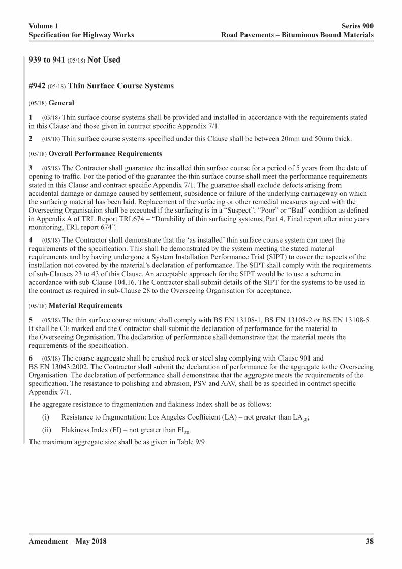
Volume 1 Series 900 Specification for Highway Works Road Pavements – Bituminous Bound Materials
38Amendment – May 2018
939 to 941 (05/18) Not Used
#942 (05/18) Thin Surface Course Systems
(05/18) General
1 (05/18) Thin surface course systems shall be provided and installed in accordance with the requirements stated in�this�Clause�and�those�given�in�contract�specific�Appendix�7/1.
2 (05/18)�Thin�surface�course�systems�specified�under�this�Clause�shall�be�between�20mm�and�50mm�thick.
(05/18) Overall Performance Requirements
3 (05/18) The Contractor shall guarantee the installed thin surface course for a period of 5 years from the date of opening�to�traffic.�For�the�period�of�the�guarantee�the�thin�surface�course�shall�meet�the�performance�requirements�stated�in�this�Clause�and�contract�specific�Appendix�7/1.�The�guarantee�shall�exclude�defects�arising�from�accidental damage or damage caused by settlement, subsidence or failure of the underlying carriageway on which the surfacing material has been laid. Replacement of the surfacing or other remedial measures agreed with the Overseeing�Organisation�shall�be�executed�if�the�surfacing�is�in�a�“Suspect”,�“Poor”�or�“Bad”�condition�as�defined�in Appendix A of TRL Report TRL674 – “Durability of thin surfacing systems, Part 4, Final report after nine years monitoring, TRL report 674”.
4 (05/18) The Contractor shall demonstrate that the ‘as installed’ thin surface course system can meet the requirements�of�the�specification.�This�shall�be�demonstrated�by�the�system�meeting�the�stated�material�requirements and by having undergone a System Installation Performance Trial (SIPT) to cover the aspects of the installation not covered by the material’s declaration of performance. The SIPT shall comply with the requirements of sub-Clauses 23 to 43 of this Clause. An acceptable approach for the SIPT would be to use a scheme in accordance with sub-Clause 104.16. The Contractor shall submit details of the SIPT for the systems to be used in the contract as required in sub-Clause 28 to the Overseeing Organisation for acceptance.
(05/18) Material Requirements
5 (05/18) The thin surface course mixture shall comply with BS EN 13108-1, BS EN 13108-2 or BS EN 13108-5. It shall be CE marked and the Contractor shall submit the declaration of performance for the material to the Overseeing Organisation. The declaration of performance shall demonstrate that the material meets the requirements�of�the�specification.
6 (05/18) The coarse aggregate shall be crushed rock or steel slag complying with Clause 901 and BS EN 13043:2002. The Contractor shall submit the declaration of performance for the aggregate to the Overseeing Organisation. The declaration of performance shall demonstrate that the aggregate meets the requirements of the specification.�The�resistance�to�polishing�and�abrasion,�PSV�and�AAV,�shall�be�as�specified�in�contract�specific�Appendix 7/1.
The�aggregate�resistance�to�fragmentation�and�flakiness�Index�shall�be�as�follows:
(i)� Resistance�to�fragmentation:�Los�Angeles�Coefficient�(LA)�–�not�greater�than�LA30;
(ii) Flakiness Index (FI) – not greater than FI20.
The�maximum�aggregate�size�shall�be�as�given�in�Table�9/9
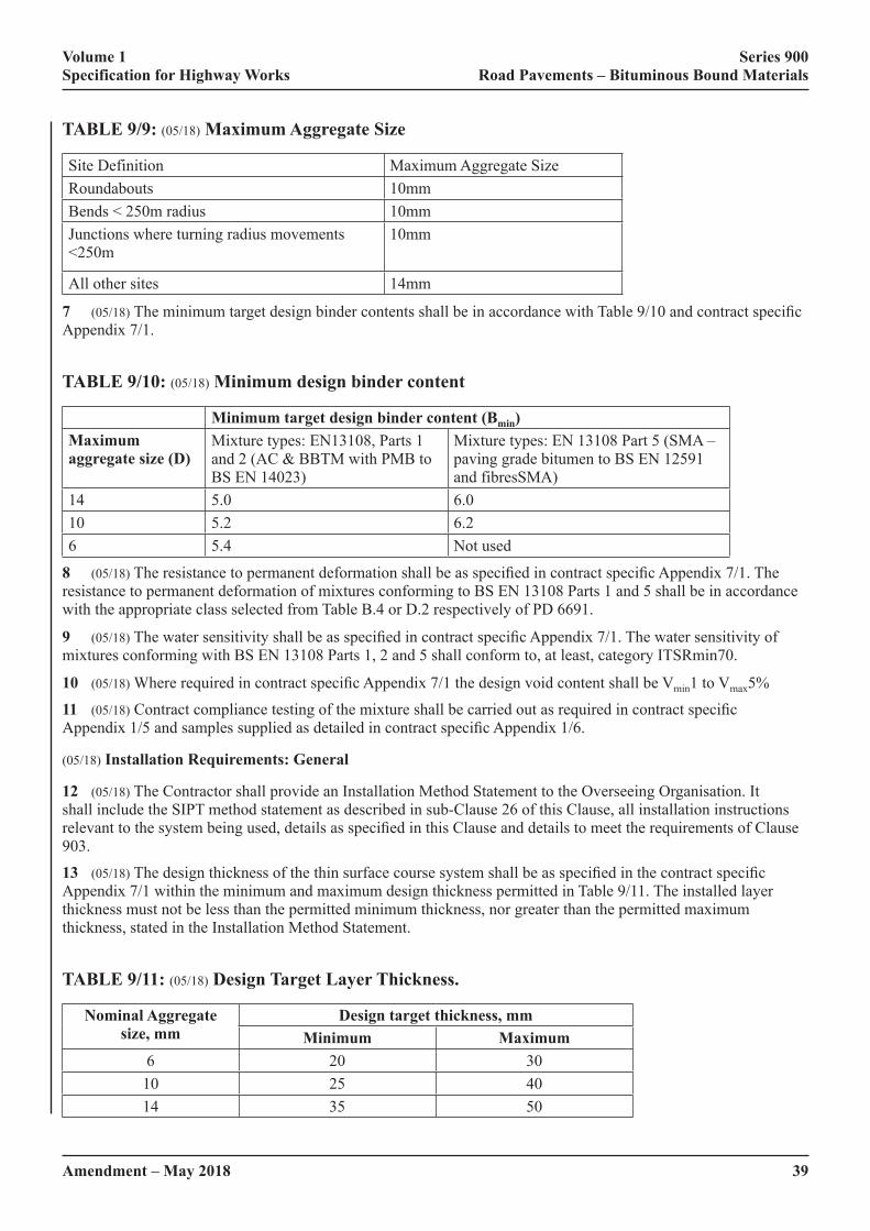
Volume 1 Series 900 Specification for Highway Works Road Pavements – Bituminous Bound Materials
Amendment – May 2018 39
TABLE 9/9: (05/18) Maximum Aggregate Size
Site Definition Maximum�Aggregate�SizeRoundabouts 10mmBends < 250m radius 10mmJunctions�where�turning�radius�movements�<250m
10mm
All other sites 14mm
7 (05/18)�The�minimum�target�design�binder�contents�shall�be�in�accordance�with�Table�9/10�and�contract�specific�Appendix 7/1.
TABLE 9/10: (05/18) Minimum design binder content
Minimum target design binder content (Bmin)Maximum aggregate size (D)
Mixture types: EN13108, Parts 1 and 2 (AC & BBTM with PMB to BS EN 14023)
Mixture types: EN 13108 Part 5 (SMA – paving grade bitumen to BS EN 12591 and fibresSMA)
14 5.0 6.010 5.2 6.26 5.4 Not used
8 (05/18)�The�resistance�to�permanent�deformation�shall�be�as�specified�in�contract�specific�Appendix�7/1.�The�resistance to permanent deformation of mixtures conforming to BS EN 13108 Parts 1 and 5 shall be in accordance with the appropriate class selected from Table B.4 or D.2 respectively of PD 6691.
9 (05/18)�The�water�sensitivity�shall�be�as�specified�in�contract�specific�Appendix�7/1.�The�water�sensitivity�of�mixtures conforming with BS EN 13108 Parts 1, 2 and 5 shall conform to, at least, category ITSRmin70.
10 (05/18)�Where�required�in�contract�specific�Appendix�7/1�the�design�void�content�shall�be�Vmin1 to Vmax5%
11 (05/18)�Contract�compliance�testing�of�the�mixture�shall�be�carried�out�as�required�in�contract�specific�Appendix�1/5�and�samples�supplied�as�detailed�in�contract�specific�Appendix�1/6.
(05/18) Installation Requirements: General
12 (05/18) The Contractor shall provide an Installation Method Statement to the Overseeing Organisation. It shall include the SIPT method statement as described in sub-Clause 26 of this Clause, all installation instructions relevant�to�the�system�being�used,�details�as�specified�in�this�Clause�and�details�to�meet�the�requirements�of�Clause�903.
13 (05/18)�The�design�thickness�of�the�thin�surface�course�system�shall�be�as�specified�in�the�contract�specific�Appendix 7/1 within the minimum and maximum design thickness permitted in Table 9/11. The installed layer thickness must not be less than the permitted minimum thickness, nor greater than the permitted maximum thickness, stated in the Installation Method Statement.
TABLE 9/11: (05/18) Design Target Layer Thickness.
Nominal Aggregate size, mm
Design target thickness, mmMinimum Maximum
6 20 3010 25 4014 35 50

Volume 1 Series 900 Specification for Highway Works Road Pavements – Bituminous Bound Materials
40Amendment – May 2018
14 (05/18)�Where�required�in�the�Installation�Method�Statement�or�in�contract�specific�Appendix�7/1,�to�achieve�final�pavement�levels�and/or�thicknesses�the�existing�substrate�surface�shall�be�strengthened�or�regulated�in�accordance with Clause 907.
15 (05/18) Where the existing substrate surface is regulated in accordance with Clause 907, evidence that the deformation�resistance�of�the�regulating�material�will�meet�the�specification�shall�be�submitted�by�the�Contractor�to�the Overseeing Organisation. Where the combined thickness of the regulating material and the thin surface course is more than 20 mm, evidence of the deformation resistance of the combined layers shall be provided.
16 (05/18) Surface preparation including the removal of road markings, cleaning and drying, resetting of ironwork and road studs shall be in accordance with BS 594987 and the Installation Method Statement.
17 (05/18) Where required in the Installation Method Statement a bond coat or tack coat shall be applied. It shall be in accordance with the Installation Method Statement. Unless otherwise stated in the Installation Method Statement is shall also comply with Clause 920 and BS 594987. A calibrated mechanised method of application shall be used unless otherwise agreed with the Overseeing Organisation.
18 (05/18) Transportation of the thin surface course material shall be in accordance with the System Installation Method Statement and Clause 903.
(05/18) Installation Requirements: Surface Macrotexture – Untrafficked
19 (05/18) The surface macrotexture depth of the thin surface course system shall be measured in accordance with�BS�EN�13036-1.�Unless�otherwise�stated�in�contract�specific�Appendix�7/1�the�macrotexture�of�the�installed�surfacing shall comply with the relevant section of Table 9/12 or Table 9/13.
TABLE 9/12: (05/18) Requirements for Initial Texture Depth for Trunk Roads including Motorways for Thin Surface Course Systems
Road Type Surfacing TypeAverage per 1,000 m
section, mmAverage for a set of 10 Measurements,
mm (minimum)Minimum Maximum
High speed roads Upper (D)�aggregate�size�of�14mm 1.3 1.8 1.0Upper (D)�aggregate�size�of�10mm 1.1 1.6 0.9Upper (D)�aggregate�size�of�6mm 1.0 1.5 0.9
Lower speed roads Upper (D)�aggregate�size�of�14mm�or�less: 1.0 1.5 0.9
Roundabouts on high speed roads Upper (D)�aggregate�size�of�10mm 1.1 1.6 0.9
Roundabouts on lower speed roads
Upper (D)�aggregate�size�of�10mm 1.0 1.5 0.9Upper (D)�aggregate�size�of�6mm 1.0 1.5 0.9
High�Speed�Roads�are�those�with�a�posted�speed�limit�≥�50�miles/h�(80�km/h) Lower�Speed�Roads�are�those�with�a�posted�speed�limit�≤�40�miles/h�(65�km/h)
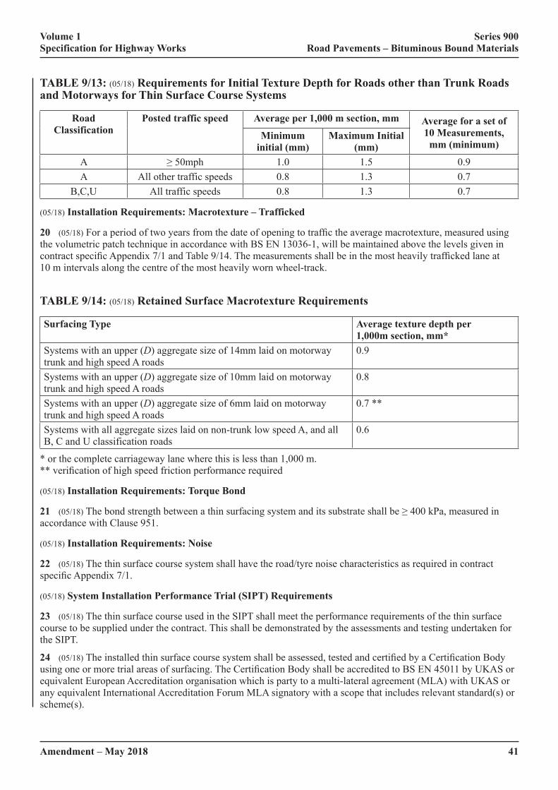
Volume 1 Series 900 Specification for Highway Works Road Pavements – Bituminous Bound Materials
Amendment – May 2018 41
TABLE 9/13: (05/18) Requirements for Initial Texture Depth for Roads other than Trunk Roads and Motorways for Thin Surface Course Systems
Road Classification
Posted traffic speed Average per 1,000 m section, mm Average for a set of 10 Measurements,
mm (minimum)Minimum
initial (mm)Maximum Initial
(mm)A ≥�50mph 1.0 1.5 0.9A All other traffic speeds 0.8 1.3 0.7
B,C,U All traffic speeds 0.8 1.3 0.7
(05/18) Installation Requirements: Macrotexture – Trafficked
20 (05/18)�For�a�period�of�two�years�from�the�date�of�opening�to�traffic�the�average�macrotexture,�measured�using�the volumetric patch technique in accordance with BS EN 13036-1, will be maintained above the levels given in contract�specific�Appendix�7/1�and�Table�9/14.�The�measurements�shall�be�in�the�most�heavily�trafficked�lane�at�10 m intervals along the centre of the most heavily worn wheel-track.
TABLE 9/14: (05/18) Retained Surface Macrotexture Requirements
Surfacing Type Average texture depth per 1,000m section, mm*
Systems with an upper (D)�aggregate�size�of�14mm�laid�on�motorway�trunk and high speed A roads
0.9
Systems with an upper (D)�aggregate�size�of�10mm�laid�on�motorway�trunk and high speed A roads
0.8
Systems with an upper (D)�aggregate�size�of�6mm�laid�on�motorway�trunk and high speed A roads
0.7 **
Systems�with�all�aggregate�sizes�laid�on�non-trunk�low�speed�A,�and�all�B, C and U classification roads
0.6
* or the complete carriageway lane where this is less than 1,000 m. **�verification�of�high�speed�friction�performance�required
(05/18) Installation Requirements: Torque Bond
21 (05/18)�The�bond�strength�between�a�thin�surfacing�system�and�its�substrate�shall�be�≥�400�kPa,�measured�in�accordance with Clause 951.
(05/18) Installation Requirements: Noise
22 (05/18) The thin surface course system shall have the road/tyre noise characteristics as required in contract specific�Appendix�7/1.
(05/18) System Installation Performance Trial (SIPT) Requirements
23 (05/18) The thin surface course used in the SIPT shall meet the performance requirements of the thin surface course to be supplied under the contract. This shall be demonstrated by the assessments and testing undertaken for the SIPT.
24 (05/18)�The�installed�thin�surface�course�system�shall�be�assessed,�tested�and�certified�by�a�Certification�Body�using�one�or�more�trial�areas�of�surfacing.�The�Certification�Body�shall�be�accredited�to�BS�EN�45011�by�UKAS�or�equivalent�European�Accreditation�organisation�which�is�party�to�a�multi-lateral�agreement�(MLA)�with�UKAS�or�any equivalent International Accreditation Forum MLA signatory with a scope that includes relevant standard(s) or scheme(s).
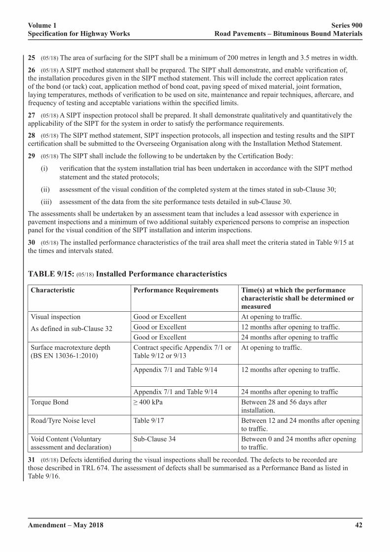
Volume 1 Series 900 Specification for Highway Works Road Pavements – Bituminous Bound Materials
42Amendment – May 2018
25 (05/18) The area of surfacing for the SIPT shall be a minimum of 200 metres in length and 3.5 metres in width.
26 (05/18)�A�SIPT�method�statement�shall�be�prepared.�The�SIPT�shall�demonstrate,�and�enable�verification�of,�the installation procedures given in the SIPT method statement. This will include the correct application rates of the bond (or tack) coat, application method of bond coat, paving speed of mixed material, joint formation, laying�temperatures,�methods�of�verification�to�be�used�on�site,�maintenance�and�repair�techniques,�aftercare,�and�frequency�of�testing�and�acceptable�variations�within�the�specified�limits.
27 (05/18) A SIPT inspection protocol shall be prepared. It shall demonstrate qualitatively and quantitatively the applicability of the SIPT for the system in order to satisfy the performance requirements.
28 (05/18) The SIPT method statement, SIPT inspection protocols, all inspection and testing results and the SIPT certification�shall�be�submitted�to�the�Overseeing�Organisation�along�with�the�Installation�Method�Statement.
29 (05/18)�The�SIPT�shall�include�the�following�to�be�undertaken�by�the�Certification�Body:
(i)� verification�that�the�system�installation�trial�has�been�undertaken�in�accordance�with�the�SIPT�method�statement and the stated protocols;
(ii) assessment of the visual condition of the completed system at the times stated in sub-Clause 30;
(iii) assessment of the data from the site performance tests detailed in sub-Clause 30.
The assessments shall be undertaken by an assessment team that includes a lead assessor with experience in pavement inspections and a minimum of two additional suitably experienced persons to comprise an inspection panel for the visual condition of the SIPT installation and interim inspections.
30 (05/18) The installed performance characteristics of the trail area shall meet the criteria stated in Table 9/15 at the times and intervals stated.
TABLE 9/15: (05/18) Installed Performance characteristics
Characteristic Performance Requirements Time(s) at which the performance characteristic shall be determined or measured
Visual inspection
As defined in sub-Clause 32
Good or Excellent At opening to traffic.Good or Excellent 12 months after opening to traffic.Good or Excellent 24 months after opening to traffic
Surface macrotexture depth (BS EN 13036-1:2010)
Contract specific Appendix 7/1 or Table 9/12 or 9/13
At opening to traffic.
Appendix 7/1 and Table 9/14 12 months after opening to traffic.
Appendix 7/1 and Table 9/14 24 months after opening to trafficTorque Bond ≥�400�kPa Between 28 and 56 days after
installation.Road/Tyre Noise level Table 9/17 Between 12 and 24 months after opening
to traffic.Void Content (Voluntary assessment and declaration)
Sub-Clause 34 Between 0 and 24 months after opening to traffic.
31 (05/18)�Defects�identified�during�the�visual�inspections�shall�be�recorded.�The�defects�to�be�recorded�are�those described in TRL 674. The assessment of defects shall be summarised as a Performance Band as listed in Table 9/16.
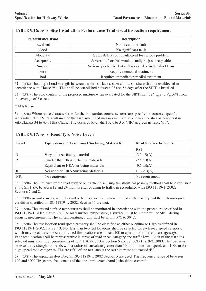
Volume 1 Series 900 Specification for Highway Works Road Pavements – Bituminous Bound Materials
Amendment – May 2018 43
TABLE 9/16: (05/18) Site Installation Performance Trial visual inspection requirement
Performance Band DescriptionExcellent No discernible fault
Good No significant faultModerate Some defects but insufficient for serious problem
Acceptable Several defects but would usually be just acceptableSuspect Seriously defective but still serviceable in the short term
Poor Requires remedial treatmentBad Requires immediate remedial treatment
32 (05/18) The torque bond strength between the thin surface course and its substrate shall be established in accordance with Clause 951. This shall be established between 28 and 56 days after the SIPT is installed.
33 (05/18) The void content of the proposed mixture when evaluated for the SIPT shall be Vmin2 to Vmax6% from the average of 6 cores.
(05/18) Noise
34 (05/18)�Where�noise�characteristics�for�the�thin�surface�course�systems�are�specified�in�contract�specific�Appendix 7/1 the SIPT shall include the assessment and measurement of noise characteristics as described in sub- Clauses 34 to 43 of this Clause. The declared level shall be 0 to 3 or ‘NR’ as given in Table 9/17.
TABLE 9/17: (05/18) Road/Tyre Noise Levels
Level Equivalence to Traditional Surfacing Materials Road Surface InfluenceRSI
3 Very quiet surfacing material -3.5 dB(A)2 Quieter than HRA surfacing materials -2.5 dB(A)1 Equivalent to HRA surfacing materials -0.5 dB(A)0 Noisier than HRA Surfacing Materials +1.2 dB(A)NR No requirement No requirement
35 (05/18)�The�influence�of�the�road�surface�on�traffic�noise�using�the�statistical�pass-by�method�shall�be�established�at�the�SIPT�site�between�12�and�24�months�after�opening�to�traffic�in�accordance�with�ISO�11819-1:�2002,�Sections 7 and 8.
36 (05/18) Acoustic measurements shall only be carried out when the road surface is dry and the meteorological condition�specified�in�ISO�11819-1:�2002,�Section�11�are�met.
37 (05/18) The air and surface temperatures shall be monitored in accordance with the procedure described in ISO 11819-1: 2002, clause 8.5. The road surface temperature, T surface, must be within 5°C to 50°C during acoustic measurements. The air temperature, T air, must be within 5°C to 30°C.
38 (05/18)�The�test�location�road�speed�category�shall�be�classified�as�either�Medium�or�High�as�defined�in�ISO 11819-1: 2002, clause 3.3. Not less than two test locations shall be selected for each road speed category, which may be at the same site, provided the locations are at least 100 m apart or on different carriageways. Each�test�location�shall�be�representative�in�terms�of�road�speed�category�and�traffic�level.�Each�of�the�test�sites�selected must meet the requirements of ISO 11819-1: 2002 Section 6 and ISO/CD 11819-2: 2000. The road must be essentially straight, or bends with a radius of curvature greater than 500 m for medium-speed, and 1000 m for high- speed road categories. The crossfall of the test lane at the test site must not exceed 4%.
39 (05/18) The apparatus described in ISO 11819-1: 2002 Section 5 are used. The frequency range of between 100�and�5000�Hz�(centre�frequencies�of�the�one-third�octave�bands)�should�be�covered.

Volume 1 Series 900 Specification for Highway Works Road Pavements – Bituminous Bound Materials
44Amendment – May 2018
40 (05/18) The macrotexture of the road surface used for the noise assessment shall be measured in the nearside wheel-track along the whole length of test material in accordance BS EN 13036-1:2010. The macrotexture depth of the nearside wheel-track in front of a test location must be within 10 per cent of the average macrotexture measured along the site.
41 (05/18) The microphone location at each measurement site shall be recorded accurately and marked with appropriate�methods�such�that�the�position�can�be�readily�identified�for�a�period�of�at�least�two�years.
42 (05/18)�When�sufficient�vehicle�pass-bys’�have�been�measured,�a�linear�regression�analysis�shall�be�performed�in accordance with ISO 11819-1: 2002, clause 9.1. In the case of the high-speed road category, measurements must not be taken of vehicles travelling at speeds of less than 60 km/h in accordance with AFNOR Standard S31-119.
43 (05/18)�For�each�category�of�vehicle�defined�in�Table�9/18,�the�Vehicle�Sound�Level,�Lveh, shall be calculated as the ordinate sound level of the regression line at the reference speed for the category of road. All levels shall be calculated to two decimal places and rounded to one decimal place.
TABLE 9/18: (05/18) Reference speeds (km•h-1) for different road speed categories
Vehicle category
Road speed category (km·h-1) Medium High
L 80 110H1 70 90H2 70 90
Category L vehicles — light vehicles including passenger cars and car derived vans, excluding vehicles towing trailers. Category H1 vehicles — commercial trucks with 2 axles and greater than 3.5 tonnes. Category H2 vehicles — commercial trucks with more than 2 axles and greater than 3.5 tonnes.
943 (05/18) Hot Rolled Asphalt Surface Course and Binder Course (Performance-Related Design Mixtures)
1 (05/18) HRA Performance Related surface course shall conform to BS EN 13108-4 and follow the example from�BSI�PD�6691�Annex�C�section�C.2.5.1.4,�the�requirements�of�this�Clause�and�those�specified�in�contract�specific�Appendix�7.1.
This mixture can be laid at lower layers within special pavement types, e.g bridge decks, when it is unchipped.
(05/18) Layer Thickness
2 (05/18) The nominal thickness of the hot rolled asphalt surface course layer shall be either 45 mm or 50 mm unless�otherwise�specified�in�contract�specific�Appendix�7/1.
(05/18) Binder and Binder Modification
3 (05/18)�Bitumen�processed�during�refining�to�provide�a�binder�with�enhanced�properties�without�the�addition�of�a�modifier,�shall�have�a�HAPAS�certificate�or�equivalent�product�acceptance�scheme�certification.
4 (05/18) For binders that do not comply with Clause 901 and without HAPAS or equivalent product acceptance scheme�certification,�the�Contractor�shall�provide�data�sheets�giving�details�of�the�properties�of�modified�binders,�whether�the�modifier�is�pre-blended�with�bitumen,�the�bitumen�is�modified�during�refinery�processing�or�modified�by�addition�into�the�asphalt�mixer,�including�those�specified�in�contract�specific�Appendix�7/1.�These�shall�include�rheological data in accordance with BS EN 14770 and cohesion in accordance with BS EN 13588. Binders that do not comply with Clause 901 or sub-Clause 3 of this Clause shall not be used without the approval of the Overseeing Organisation.

Volume 1 Series 900 Specification for Highway Works Road Pavements – Bituminous Bound Materials
Amendment – May 2018 45
(05/18) Coarse Aggregate
5 (05/18) Coarse aggregate shall be crushed rock or slag complying with BS EN 13043:2002 and Clause 901. The resistance to polishing of the coarse aggregate for surface course shall comply with category PSV44 in accordance with BS EN 13043:2002, clause 4.2.3.
(05/18) Deformation Resistance
6 (05/18) The resistance to permanent deformation of the mixture shall be in accordance with the appropriate class selected�from�Table�C.3�of�BSI�PD�6691,�as�specified�in�contract�specific�Appendix�7/1.
(05/18) Coated Chippings for Surface Course
7 (05/18)�When�required,�coated�chippings�shall�be�14/20�mm�or�8/14�mm�size�as�specified�in�contract�specific�Appendix 7/1 and comply with Clause 915.
(05/18) Surface Macrotexture for Surface Course
8 (05/18) The surface macrotexture shall comply with Clause 921.
(05/18) Compaction Control Procedures
9 (05/18) Control testing for compaction and resistance to permanent deformation shall be carried out in accordance with BS 594987 section 9.5.2.
10 (05/18)�When�specified�in�the�contract�specific�Appendix�7/1,�the�resistance�to�permanent�deformation�of�material laid in the permanent works shall be monitored by testing in accordance with clause F.3 of BS 594987 Annex�F.�Six�cores�shall�be�taken�from�the�first�kilometre�length�of�material�from�each�mixing�plant�and�thereafter�one further core from each subsequent lane kilometre. Results shall be assessed on successive rolling means of sets of�six�consecutive�results�and�shall�be�deemed�to�conform�if�the�mean�is�no�greater�than�the�specified�value�and�individual�values�not�more�than�50%�greater�than�the�specified�value.
(05/18) Trafficking Newly Laid Surfacing
11 (05/18) The Contractor shall ensure the pavement material has adequately cooled and hardened before the road is�opened�to�traffic.�Unless�otherwise�agreed�by�the�Overseeing�Organisation,�the�road�shall�not�be�opened�to�traffic�if its surface temperature exceeds 25°C unless the maximum temperature within the mat has fallen below 35°C.
944 (05/18) Not Used
945 (05/18) Weather Conditions for Laying of Hot Bituminous Mixtures
1 (05/18) The Contractor shall take account of the weather conditions when planning his working methods. The Contractor’s working methods shall comply with all weather-related requirements of BS 594987 and any additional requirements of this Clause. When laying is to be undertaken during winter (October to April) and/or night�time�(9�p.m.�to�6�a.m.),�the�contractor�shall�work�to�a�Quality�Plan�that�allows�for�the�specific�issues�raised�by�winter and/or night time working.
2 (05/18) Hot bituminous materials laid less than 50 mm thick, other than those supplied to Clause 942, shall be laid within the wind speed and temperature constraints of Figure 9/1.
(05/18) Thin Surface Course Systems
3 (05/18)�The�weather�conditions�for�laying�thin�surface�course�systems�shall�comply�with�those�identified�as�being acceptable in the Installation Method Statement as required in Clause 942.

Volume 1 Series 900 Specification for Highway Works Road Pavements – Bituminous Bound Materials
46Amendment – May 2018
(05/18) Hot Rolled Asphalt With Pre-coated Chippings
4 (05/18) Hot rolled asphalt surface course mixtures incorporating 35% coarse aggregate with pre-coated chippings shall be laid 50 mm thick, within the following constraints of delivery temperature, wind speed and air temperature.
Air temperature (minimum): 0°C
Wind speed (maximum at any air temperature):
40 km/h (at 2 m height)
or
50 km/h (at 10 m height)Minimum delivery temperature of materials: 155°C.
(05/18) Wind Speed
5 (05/18) When measurements are required for assessment, wind speed shall be measured by anemometer positioned�near�the�laying�site�to�accurately�reflect�conditions�at�the�laying�site.�The�anemometer�shall�be�fitted�with�a digital accumulative device.
FIGURE 9/1: (05/18) Wind Speed and Air Temperature Laying Restrictions for Layers Less Than 50 mm Thick
946 (05/18) Local Repairs
(05/18) General
1 (05/18)�Local�repair�is�defined�as�the�reinstatement�of�surface�course,�and�binder�course�and�base�if�necessary,�over a relatively small area.
2 (05/18) Areas of defectiveness greater than 1m2 shall be repaired by inset replacement over a length and width in accordance with sub-Clause 702.10(iv) and sub-Clause 903.21. Areas of defectiveness up to 1m2 in surface area may be repaired using an inset patch. The repair technique used shall be as given in Table 9/19.

Volume 1 Series 900 Specification for Highway Works Road Pavements – Bituminous Bound Materials
Amendment – May 2018 47
TABLE 9/19: (05/18) Repair Technique
Size ( approx m2) Application Repair technique
Up to 1.0Individual pothole or road stud hole. Discrete area of local defectiveness
Inset patch
In excess of 1.0 or several closely adjacent areas less than 1.0
Wide area of local defectiveness.
Replacement for minimum length of 5m or 15m in accordance with sub-Clause 702.10 (iv). Full lane width or less where practicable, joints to comply with sub-Clause 903.21.
(05/18) Inset Patch Repair for Areas ≤ 1.0m2 – Preparation
3 (05/18) The edges of the repair shall be saw-cut or planed in a neat rectangular shape in sound surfacing at a distance of at least 0.25m beyond the defective area. The saw-cut or planed opening shall have vertical straight edges and extend for the full depth of surface course. For repairs that extend into the binder course and/or base these lower layers may be removed by the use of a mechanical breaker. An offset stepped detail for the binder and base layers shall be used to ensure that vertical joints do not pass through more than one layer at the same location. A�minimum�horizontal�step�of�100mm�shall�be�provided�at�all�layer�interfaces.
4 (05/18) All existing material within the saw-cut perimeter of the repair area shall be removed and the base and sides of the cavity thoroughly cleansed of all loose material and moisture to provide clean and dry surfaces throughout.
5 The prepared vertical joints and the base of the cavity shall be treated in accordance with sub-Clause 903.22.
(05/18) Inset Patch Repair for Areas ≤ 1.0m2 – Repair Materials
6 (05/18)�Repair�materials�shall�comply�with�the�specification�requirements�stated�in�contract�specific�Appendix�7/1.�Unless�otherwise�stated�in�contract�specific�Appendix�7/1�repair�materials�shall�be�consistent�with,�and compatible to, the surrounding materials.
7 (05/18) Repair materials for patches in hot rolled asphalt surfacing shall be in accordance with Clause 911.
(05/18) Inset Patch Repair for Areas ≤ 1.0m2 – Construction
8 (05/18) Construction of the repair should commence at the edges and progress inwards with particular care for full compaction especially in the vicinity of the vertical joint faces. All construction layers shall be laid and compacted such that on completion each layer shall be at the same level as the adjacent course.
9 (05/18) The repair material must be compacted using rollers, vibrating plates and/or tampers as appropriate for the�size�of�the�repair.�The�corners�of�the�repair�are�the�most�vulnerable�to�distress�and�particular�care�must�be�taken�to achieve full compaction in these areas.
(05/18) Repair Areas >1.0m2
10 (05/18) Large areas shall only be repaired with materials installed using full scale self-propelled paving machinery. The extent of the repair area shall be as described in sub-Clause 702.10(iv) with appropriate longitudinal and transverse joints in accordance with sub-Clause 903.21.
11 (05/18) Repairs to large areas in Thin Surface Course Systems shall be undertaken in accordance with the instructions�stated�in�contract�specific�Appendix�7/1.
12 (05/18)�Repair�materials�shall�comply�with�the�specification�requirements�stated�in�contract�specific�Appendix�7/1.�Unless�otherwise�stated�in�contract�specific�Appendix�7/1�repair�materials�shall�be�consistent�with,�and compatible to, the surrounding materials.
13 (05/18) Areas exceeding 1m2 in existing hot rolled asphalt surfacing shall be repaired using hot rolled asphalt material in accordance with Clause 911.

Volume 1 Series 900 Specification for Highway Works Road Pavements – Bituminous Bound Materials
48Amendment – May 2018
14 (05/18) Placing and compaction shall be in accordance with Clause 903 and BS594987 with use of bond coat in accordance with Clause 920.
(05/18) Proprietary Materials and Techniques for Repairs ≤ 1.0m2
15 (05/18) Evidence from laboratory evaluation shall be provided by the Contractor to the Overseeing Organisation to demonstrate that the proprietary repair materials and/or techniques comply with the following performance criteria:
• Stiffness:�≥1�GPa�after�28�days�when�tested�in�accordance�with�BS�EN�12697-26�(ITSM�method�20°C)
• Resistance�to�permanent�deformation:�Classification�No.�1�as�defined�in�Table�D.2�of�BSI�PD�6691
16 (05/18) Data from a representative area of the material and/or technique, for a local repair >2m2�in�size,�must�be�provided�to�demonstrate�that�the�finished�surface�to�be�trafficked�complies�with�the�following:
• The initial surface texture shall be not less than 0.9mm when measured using the volumetric patch method described in BS EN 13036-1
• The minimum wet Skid Resistance value shall not be less than 60 when determined using the portable skid resistance tester (pendulum) in accordance with BS EN 13036-4.
947 (05/18) In Situ Cold Recycled Bitumen Bound Material
(05/18) Scope
1 (05/18) In situ cold recycled bitumen bound material shall be designed and produced to form the foundation or main structural layer of the road pavement. The primary aggregate source shall be obtained by cold pulverisation of all, or part, of the existing road structure. The primary binder (stabilising agent) shall be a foamed bitumen, with cement�or�lime�as�an�adhesion�agent.�The�aggregate�grading�may�be�adjusted�by�the�addition�of�a�filler.�Lime�may�also be used to modify any cohesive sub-grade soil incorporated in the pulverised layer.
2 (05/18) Prior to commencing the pulverisation and stabilisation works, the Contractor shall demonstrate, to the satisfaction of the Overseeing Organisation, using the results of mix design procedures described in sub-Clauses 58 to�65�of�this�Clause,�that�the�existing�pavement�materials�in�the�sections�of�the�works�defined�in�contract�specific�Appendix 7/18 are capable of being recycled by pulverisation to form the primary aggregate component of an in situ�cold�recycled�bitumen�bound�material�which�can�meet�the�specified�end-product�performance�requirements.
(05/18) Component Materials
(05/18) Aggregates and Fillers
3 (05/18)�The�pulverised�pavement�material�and�any�supplementary�aggregate�and/or�filler�shall�normally�be�granular material with not less than 5% and not more than 20% passing the 0.063 mm sieve (Zone A graded material). Approval for use of pulverised granular material containing up to 35% passing the 0.063 mm sieve (Zone�B�graded�material)�shall�require�confirmation�by�the�Overseeing�Organisation,�subject�to�the�results�of�the�mixture design procedures described in sub-Clauses 58 to 65 of this Clause.
4 (05/18) The pulverised granular material shall contain not more than 2% of organic matter as determined in accordance with BS 1377-3 clause 3.
(05/18) Bitumen Binder
5 (05/18) The primary binder shall be foamed bitumen. The base bitumen shall comply with BS EN 12591 and shall be 100/150 penetration grade.
6 (05/18)�Other�than�foaming�agent(s),�bitumen�modifiers�shall�not�be�used�unless�approved�by�the�Overseeing�Organisation for special purposes or conditions.
Volume 1 Series 900 Specification for Highway Works Road Pavements – Bituminous Bound Materials
Amendment – May 2018 49
7 (05/18) The binder shall be transported to the site in tankers capable of maintaining the required temperature and a homogeneous binder consistency and transferred to the stabilising plant in a controlled and uniform manner.
8 (05/18) The foaming of the bitumen shall be carried out within the spraybar system of the recycling machine and immediately mixed with the pulverised aggregate, at which point the foamed bitumen shall have a volume of not less than 10 times the volume of the base penetration grade bitumen.
(05/18) Cement, Filler Aggregate and Lime
9 (05/18)�The�constituents�and�required�quality�standards�of�hydraulic�cement,�filler�aggregate�and�lime�delivered�to�site�shall�be�certified�by�the�supplier,�whose�manufacturing�and�delivery�processes�shall�be�implemented�using�quality�management�systems�in�accordance�with�the�BS�EN�ISO�9001�and�certified�by�an�accredited�body.
10 (05/18)�Hydraulic�cement�as�a�filler�aggregate�or�adhesion�agent�shall�be�cement,�blast�furnace�slag�cement�or�PFA cement, in accordance with sub-Clause 1001.3.
11 (05/18)�PFA,�used�as�a�filler�aggregate,�shall�be�in�accordance�with�BS�EN�450-1.
12 (05/18)�Lime�for�lime�stabilisation�(or�as�a�modifier�for�plastic�fines)�shall,�as�required�in�contract�specific�Appendix 7/18, be either quicklime or hydrated lime, complying with sub-Clause 615.3.
(05/18) Water
13 (05/18) Water for moisture content control of the pulverised granular material, shall normally be obtained from a water company supply and used without testing. Water from an alternative source shall comply with BS EN 1008 and be approved by the Overseeing Organisation.
(05/18) Pulverisation and Stabilisation
14 (05/18) The Contractor shall satisfy the Overseeing Organisation that the plant used for pulverisation is capable�of�uniformly�pulverising�the�existing�road�structure�in�a�single�pass,�to�the�depth�stated�in�contract�specific�Appendix 7/18. The plant used for stabilisation shall be capable of uniformly mixing controlled amounts of water and binder agent(s) into the full depth of pulverised layer. For either operation, the plant shall be equipped with a means�of�controlling�the�depth�of�processing�to�±15�mm�of�the�required�depth.
15 (05/18) The plant used for stabilisation shall be equipped with a spraybar system within the mixing chamber capable of producing and uniformly distributing foamed bitumen binder at a monitored and controlled rate. An accessible�sampling�jet�shall�also�be�fitted�that�produces�foamed�bitumen�having�the�same�characteristics�as�that�produced by the main spraybar. Flow rate meters for measuring the supply rate of hot bitumen and other liquid additives�to�the�mixture�shall�be�capable�of�recording�the�correct�rate�of�flow�during�all�states�of�pipeline�flow�(i.e.�fully�or�partially�charged).�Evidence�confirming�the�capabilities�of�the�plant�and�the�calibration�of�flow�meters,�shall be submitted to and approved by the Overseeing Organisation prior to the stabilisation works commencing.
16 (05/18) The material shall be pulverised and stabilised in a single layer if its compacted thickness is 300 mm or less. If the compacted thickness is greater than 300 mm, the material shall be pulverised and stabilised in the minimum number of layers between 100 mm and 300 mm thick. Where more than one layer is required, the Contractor shall satisfy the Overseeing Organisation that the lower layer has achieved adequate stability in accordance with sub-Clause 31 of this Clause before proceeding with the overlying layer.
(05/18) Pulverisation Process
17 (05/18) Pulverisation of the existing road structure shall be carried out in a systematic pattern, to the required depth,�to�ensure�that�all�parts�of�the�existing�road�designated�in�contract�specific�Appendix�7/18�are�included�in�the�works. An overlap of at least 150 mm shall be made between adjacent passes of the machine. Any material missed along hard edges or around obstructions shall be excavated and placed in the path of subsequent passes of the machine until a uniform fully pulverised aggregate is obtained. The pulverised material shall not be contaminated by material drawn in from the verges.

Volume 1 Series 900 Specification for Highway Works Road Pavements – Bituminous Bound Materials
50Amendment – May 2018
18 (05/18) All longitudinal and transverse joints shall be clean cut and vertical. Where work continues adjacent to previously recycled material, transverse joints shall be reformed a minimum 0.5 m into the previously treated construction. Where a layer of material for stabilisation is placed over a layer previously stabilised, the depth of pulverisation/stabilisation of the upper layer shall be set to cut into the underlying stabilised layer by at least 20 mm.
19 (05/18) Excess pulverised material shall be removed by the grader and/or excavator for use elsewhere on site or�transported�to�stockpile�at�locations�given�in�contract�specific�Appendix�7/18.�The�surface�of�the�layer�shall�be�graded�nominally�to�the�required�profile�and�provisionally�compacted.
20 (05/18) Moisture content of the pulverised aggregate immediately prior to stabilisation shall be measured in accordance with BS EN 1097-5 using the high temperature method. The moisture content shall be uniform throughout�the�layer�within�the�range�±2%�of�the�optimum�moisture�content�for�the�unstabilised�aggregate�including�any�designed�proportion�of�filler,�determined�in�accordance�with�BS�EN�13286-2.
21 (05/18)�If�the�moisture�content�of�the�unstabilised�pulverised�aggregate�fails�to�meet�the�specified�moisture�content range, corrective action shall be taken either by aeration to reduce the moisture content or by controlled addition of water to increase the moisture content.
22 (05/18) Aeration of the affected area shall be achieved by full depth passes of the recycling machine to disturb and loosen the material and assist the evaporation of excess moisture. The material shall be kept in a loose condition until subsequent moisture content tests show that the treated material has reached the required moisture content�range.�The�layer�shall�be�re-graded�nominally�to�the�required�profile�and�provisionally�compacted�in�preparation for stabilisation.
23 (05/18) An increase in moisture content of the affected area shall be achieved by the addition of water through an adjustable spraybar system in conjunction with full depth passes of the recycling machine to achieve a uniform distribution of the water throughout the layer. Increments of water shall be added and mixed in until subsequent moisture content tests show that the material has reached the required moisture content range. The layer shall be re-graded�nominally�to�the�required�profile�and�provisionally�compacted�in�preparation�for�stabilisation.
(05/18) Stabilisation Process
24 (05/18) Stabilisation shall not be carried out during or after periods of rainfall where the duration and intensity are�likely�to�cause�the�stabilised�mixture�to�exceed�the�specified�moisture�content�criteria�and�compromise�the�stability�of�the�layer�under�compaction�(as�defined�in�sub-Clause�31�of�this�Clause).�Stabilisation�of�frozen�materials shall not be permitted.
25 (05/18) Prior to stabilisation, pulverised materials within 100 mm of restricted hard edges such as kerbs and channels, or around obstructions such as gullies, shall be removed and spread uniformly over the remaining full width of the pulverised material.
26 (05/18)�Immediately�prior�to�stabilisation,�any�filler�and/or�adhesion�agent�shall�be�spread�uniformly�over�the�full width of the layer using a mechanical spreader capable of distributing the material(s) in a uniform controlled manner. The rate of spread of these materials shall be calculated to achieve the mixture composition determined in accordance with sub-Clauses 58 to 65 of this Clause and monitored as the spreading operation proceeds in accordance with sub-Clause 35 of this Clause.
27 (05/18) The stabilisation shall be carried out to the required depth in a systematic pattern similar to that used for the pulverisation process, with an overlap of at least 150 mm between adjacent passes of the machine. The bitumen binder shall be introduced as a foamed bitumen and distributed through the spraybar system directly into the rotor and mixing box of the stabiliser. The binder shall be supplied to the spraybar of the recycling machine by pumped pipeline from on-board tanks or from a tanker moving in tandem with the recycling machine. The rate of supply of the bitumen and any foaming agent, calculated to achieve the target binder content determined in accordance with sub-Clauses 58 to 65, shall be controlled and monitored as described in sub-Clause 36 of this Clause.
28 (05/18)�The�layer�of�stabilised�material�shall�be�graded�to�level�and�compacted�within�two�hours�of�the�final�pass�of the stabilising plant, unless a curing or “maturing” period of aeration is required. Any furrow formed by prior excavation�of�edge�materials�shall�be�re-filled�by�grading�the�adjacent�stabilised�material�into�the�space�using�a�minimum amount of re-working.

Volume 1 Series 900 Specification for Highway Works Road Pavements – Bituminous Bound Materials
Amendment – May 2018 51
29 (05/18) The compaction of each layer shall be carried out using compaction plant approved by the Overseeing Organisation, until such time as the in-situ density complies with sub-Clauses 40 and 41 of this Clause and the stabilised layer provides a stable and dense surface. Any open or segregated surface area shall be blinded using dry crushed�rock�fines.
30 (05/18)�The�stability�of�the�layer�under�compaction�shall�be�deemed�adequate�if�the�finished�surface�does�not�shove,�rut�or�exhibit�transverse�cracking�under�the�load�of�subsequent�construction�traffic.
31 (05/18) Where required by the Overseeing Organisation the stability of a layer in any area shall be assessed after�a�curing�period�of�at�least�24�hours�by�channelled�trafficking�using�a�rigid�three-axle�tipper�truck�loaded�to�a�gross mass of 24 tonnes (assumed equivalent to three standard axles). The vertical deformation shall be measured in all wheel-tracks at monitoring points on each of 5 transverse sections set 1 m apart after 5, 15, 30 and 40 passes of�the�truck.�The�mean�vertical�deformations�at�the�above�trafficking�increments�shall�be�plotted�against�the�respective number of truck passes and the mean vertical deformation corresponding to 100 standard axles shall be interpolated. The layer shall be deemed acceptable if the mean vertical deformation corresponding to 100 standard axles is less than 10 mm.
32 (05/18)�On�completion�of�compaction�the�surface�shall�be�sealed�using�a�sprayed�membrane�of�Class�K1–70�bitumen emulsion complying with Clause 920. The bitumen emulsion shall be sprayed at the rate stated in contract specific�Appendix�7/18.�Where�the�surface�is�opened�to�traffic,�the�sealing�membrane�shall�be�blinded�with�fine�aggregate or sand applied at a rate of 5.5 to 7.0 kg/m2.
(05/18) Process Control
33 (05/18) The condition or quality of the pulverised material or stabilised mixture shall be assessed for specification�compliance�on�the�basis�of�each�800�m2 area of the works or part thereof, completed in the same working day.
34 (05/18)�The�moisture�content�specified�in�sub-Clause�20�of�this�Clause�shall�be�monitored�using�test�specimens�extracted from three bulk samples of pulverised aggregate taken from points evenly spaced along a diagonal bisecting the assessment area. The bulk samples shall comprise material taken from the full depth of the pulverised layer. The depth of pulverisation relative to the designed road level shall be measured and recorded at each point.�The�samples�shall�also�be�tested�to�determine�the�particle�(or�“lump”)�size�distribution�in�accordance�with�BS EN 933-1 (or by an amended method to obtain an early assessment of grading, provided correlation with the standard test method can be demonstrated). Where appropriate, the residue of the three samples shall be combined to form one bulk sample and the bitumen content of the pulverised aggregate determined in accordance with BS EN 12697-1. If any adjustment of moisture content is carried out prior to stabilisation, subsequent samples shall be taken and further moisture content tests completed.
35 (05/18)�The�rate�of�spread�of�cement,�filler,�hydrated�lime�or�quicklime�shall�be�measured�by�weighing�the�amount�of�material�retained�on�each�of�five�trays�or�mats�of�known�area�laid�in�the�path�of�the�spreading�machine.�The trays shall be positioned approximately at points equally spaced along a diagonal bisecting the area of coverage. The mean rate of spread and percentage addition of the material shall be determined and recorded for each assessment area.
36 (05/18)�The�rate�of�supply�of�bitumen�binder�and�any�other�fluids�to�the�stabilising�plant�shall�be�set�and�continuously�monitored�using�the�appropriate�flow�rate�meters�on�the�stabilising�plant.�As�a�check�at�the�start�of�each work period, the rate of supply of bitumen shall be determined from before and after dip measurements of the storage/delivery tanks, related to an area of stabilisation of not more than 250 m2. The calculated supply rate of bitumen for each test area shall be recorded.
37 (05/18) As directed by the Overseeing Organisation, where lime has been used to modify a cohesive soil component�of�the�pulverised�aggregate,�the�acceptability�of�the�modified�materials�shall�be�tested�in�accordance�with sub-Clause 615.9.
38 (05/18)�After�stabilisation,�prior�to�final�compaction�of�the�stabilised�mixture,�five�samples�of�the�stabilised�material shall be obtained. Each sample shall be taken from a point equally spaced along a diagonal bisecting the area under consideration. The location of each sampling point shall be recorded. Each sample shall comprise at least 40 kg of material taken from the full depth of the layer. The depth of stabilisation relative to the designed

Volume 1 Series 900 Specification for Highway Works Road Pavements – Bituminous Bound Materials
52Amendment – May 2018
road level shall be measured and recorded at each point. Where appropriate and as directed by the Overseeing Organisation, the depth measurements shall be made using a stringline stretched between points of known level.
39 (05/18)�In�the�field,�each�sample�of�the�stabilised�material�shall�be�mixed�in�a�tray�and�sufficient�representative�material taken to produce a 150 mm cube specimen, made in accordance with the relevant Clauses of Series 800. The refusal density for each cube sample shall be determined to the nearest 10 kg/m3. The remainder of each sample shall be retained in a sealed condition for subsequent testing on site or in the laboratory, as described in sub- Clauses 42, 43 and 46 of this Clause.
40 (05/18)�After�trimming�and�final�compaction�of�the�stabilised�layer,�the�in-situ�bulk�density�shall�be�measured�at�50 m intervals per lane, including points close to the material sampling points, using an indirect density gauge in direct�transmission�mode,�to�a�depth�within�25�mm�of�the�total�layer�thickness.�The�meter�readings�shall�be�verified�periodically in accordance with BS EN 13286-2.
41 (05/18) The in-situ bulk density values obtained shall be compared with the refusal density value obtained from the�cube�specimens�at�the�respective�sampling�points.�The�average�in-situ�bulk�density�of�each�set�of�five�values�shall be at least 95% of the cube refusal density, with no individual in-situ density value less than 93% of the respective refusal density.
42 (05/18)�Either�on�site�or�immediately�on�arrival�at�the�laboratory,�each�of�the�five�samples�shall�be�tested�for�moisture content in accordance with BS 1377-2.
43 (05/18) Either on site or within 24 hours of arrival at the laboratory, one 150 mm diameter by 75 mm to 100 mm high�cylinder�test�specimen�(briquette�specimen)�shall�be�manufactured�from�each�of�the�five�samples,�compacted�in�a�PRD�mould�to�a�target�density�of�the�average�in-situ�bulk�density�measured�in�the�field.�The�final�density�of�each briquette specimen shall be measured and using the respective moisture content values, the dry density values shall be determined.
44 (05/18)�The�curing�history�of�the�five�briquette�specimens�prior�to�testing�shall�be�recorded,�which�shall,�as�soon�as possible after manufacture, include a period of 72 hours at a nominal temperature of 60ºC. Immediately before testing, each briquette specimen shall be conditioned in air for a minimum period of 12 hours at 20ºC and then tested in accordance with BS EN 12697-26 (ITSM method) to determine the Indirect Tensile Stiffness Modulus (ITSM) of the material. After removal from the test apparatus, each briquette shall be immersed in water at 20°C for a minimum period of 24 hours, then re-tested to determine the ITSM of the material in a saturated state.
45 (05/18) The air voids content of each briquette shall be determined in accordance with BS 598-104 except that the maximum density for the partially coated product, used in the air voids content calculation, shall be standardised using the maximum density determined for a fully coated laboratory prepared specimen. A sample of loose pulverised aggregate obtained prior to the addition of foamed bitumen shall be dried to constant mass at�50°C.�Sufficient�hot�penetration�grade�bitumen�shall�then�be�added�in�increments�to�the�dried�aggregate�in�a�mechanical mixer until the mixture is visually fully coated (using of the order 4% of added bitumen). The coated specimen�shall�be�tested�to�determine�maximum�density�as�specified�in�BS�EN�12697-5.
46 (05/18)�The�residue�of�the�five�samples�of�stabilised�material�shall�be�combined�to�form�one�bulk�sample.�From�this bulk sample, four sub-samples shall be obtained. Three sub-samples shall be tested to determine the particle size�distribution�and�one�sub-sample�to�determine�bitumen�content�in�accordance�with�BS�EN�12697-1.�The�added�bitumen content shall be the measured bitumen content of the stabilised mixture, less the bitumen content of the pulverised aggregate prior to stabilisation.
47 (05/18)�The�specification�compliance�criteria�for�the�process�control�tests�shall�be�as�described�in�Table�9/20.
(05/18) End Product Performance of In Situ Cold Recycled Bitumen Bound Material
48 (05/18) The end-product performance of the in situ cold recycled bitumen bound material shall be assessed on the basis of measurements carried out in areas of 800 m2 or part thereof completed each working day which match the�areas�defined�in�sub-Clause�33�of�this�Clause.
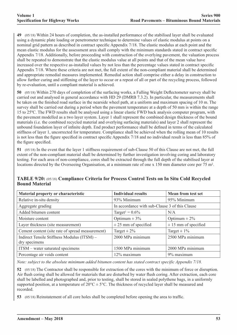
Volume 1 Series 900 Specification for Highway Works Road Pavements – Bituminous Bound Materials
Amendment – May 2018 53
49 (05/18) Within 24 hours of completion, the as-installed performance of the stabilised layer shall be evaluated using a dynamic plate loading or penetrometer technique to determine values of elastic modulus at points on a nominal�grid�pattern�as�described�in�contract�specific�Appendix�7/18.�The�elastic�modulus�at�each�point�and�the�mean�elastic�modulus�for�the�assessment�area�shall�comply�with�the�minimum�standards�stated�in�contract�specific�Appendix 7/18. Additionally, before proceeding with construction of the overlying pavement, the valuation process shall be repeated to demonstrate that the elastic modulus value at all points and that of the mean value have increased�over�the�respective�as-installed�values�by�not�less�than�the�percentage�values�stated�in�contract�specific�Appendix 7/18. Where these criteria are not met, the full extent of the non-compliant material shall be determined and appropriate remedial measures implemented. Remedial action shall comprise either a delay in construction to allow further curing and stiffening of the layer to occur or a repeat of all or part of the recycling process, followed by re-evaluation, until a compliant material is achieved.
50 (05/18)�Within�270�days�of�completion�of�the�surfacing�works,�a�Falling�Weight�Deflectometer�survey�shall�be�carried out and analysed in general accordance with HD 29 (DMRB 7.3.2). In particular, the measurements shall be�taken�on�the�finished�road�surface�in�the�nearside�wheel�path,�at�a�uniform�and�maximum�spacing�of�10�m.�The�survey shall be carried out during a period when the pavement temperature at a depth of 50 mm is within the range 15 to 25ºC. The FWD results shall be analysed using a linear elastic FWD back analysis computer program, with the pavement modelled as a two layer system. Layer 1 shall represent the combined design thickness of the bound materials (i.e. the combined recycled material and overlying surfacing materials) and layer 2 shall represent the unbound�foundation�layer�of�infinite�depth.�End�product�performance�shall�be�defined�in�terms�of�the�calculated�stiffness of layer 1, uncorrected for temperature. Compliance shall be achieved when the rolling mean of 10 results is�not�less�than�the�figure�specified�in�contract�specific�Appendix�7/18�and�no�individual�result�is�less�than�85%�of�the�figure�specified.
51 (05/18) In the event that the layer 1 stiffness requirement of sub-Clause 50 of this Clause are not met, the full extent of the non-compliant material shall be determined by further investigation involving coring and laboratory testing. For each area of non-compliance, cores shall be extracted through the full depth of the stabilised layer at locations directed by the Overseeing Organisation, at a minimum rate of one x 150 mm diameter core per 75 m2.
TABLE 9/20: (05/18) Compliance Criteria for Process Control Tests on In Situ Cold Recycled Bound Material
Material property or characteristic Individual results Mean from test setRelative in-situ density 93% Minimum 95% MinimumAggregate grading In accordance with sub-Clause 3 of this ClauseAdded bitumen content Target1 = 0.6% N/AMoisture content Optimum�±�3% Optimum�±�2%Layer thickness (site measurement) ±�25�mm�of�specified ±�15�mm�of�specifiedCement content (site rate of spread measurement) Target�±�2% Target�±�1%Indirect Tensile Stiffness Modulus (ITSM) – dry specimens
2000 MPa minimum 2500 MPa minimum
ITSM – water saturated specimens 1500 MPa minimum 2000 MPa minimumPercentage air voids content 12% maximum 9% maximum
Note: subject to the absolute minimum added bitumen content has stated contract specific Appendix 7/18.
52 (05/18) The Contractor shall be responsible for extraction of the cores with the minimum of force or disruption. Air�flush�coring�shall�be�allowed�for�materials�that�are�disturbed�by�water�flush�coring.�After�extraction,�each�core�shall be labelled and photographed and, prior to testing, shall be stored in sealed polythene bags, in a uniformly supported�position,�at�a�temperature�of�20°C�±�5°C.�The�thickness�of�recycled�layer�shall�be�measured�and�recorded.
53 (05/18)�Reinstatement�of�all�core�holes�shall�be�completed�before�opening�the�area�to�traffic.

Volume 1 Series 900 Specification for Highway Works Road Pavements – Bituminous Bound Materials
54Amendment – May 2018
54 (05/18)�If,�at�any�of�the�prescribed�core�locations,�it�is�not�possible�to�extract�an�intact�core�of�suitable�size�or�condition for the end-product performance testing, using a maximum of three attempts in an area of 1.5 m radius, the�material�in�the�vicinity�shall�be�deemed�not�to�comply�with�the�end-product�performance�specification.
55 (05/18) In the laboratory, each of the cores extracted successfully shall be trimmed to remove surfacing materials and any underlying material prior to cutting into core test specimens between 75 mm and 100 mm high. Where possible, three test specimens shall be obtained from each core, one from the upper part, one from the centre and the other from the lower part.
56 (05/18) All core test specimens thus obtained shall be tested in accordance with the standards described in Table 9/21.
TABLE 9/21: (05/18) Testing Standards for Core Specimens of In Situ Cold Recycled Bound Material
Test Standard
Bulk density BS EN 12697-6 and sub-Clause 39 of this Clause
Air voids content BS EN 12697-8 and sub-Clause 45 of this Clause
Indirect Tensile Stiffness Modulus BS EN 12697-26
57 (05/18) The results obtained shall be used for assessing the expected performance of the stabilised material in the�Works,�in�relation�to�the�known�performance�of�BS�specified�base�materials.�The�stabilised�material�in�the�trial�area shall be deemed acceptable if the compliance criteria described in Table 9/22 are met.
TABLE 9/22: (05/18) Compliance Criteria for In Situ Cold Recycled Bound Material – Core Specimens from the Works
Material property or characteristic Individual cores Mean from core setCore density relative to refusal density 93% minimum 95% minimumAir voids content 9% maximum 7% maximumLayer thickness (from core measurement) ±�25mm�of�specified ±�15mm�of�specifiedIndirect Tensile Stiffness Modulus – dry 2000 MPa minimum 2500 MPa minimum
(05/18) Mixture Design and Characterisation
58 (05/18) Mixture design and characterisation of in situ cold recycled bitumen bound material for each site, or section�of�site,�including�details�of�filler,�binder,�adhesion�and/or�stabilising�agent(s)�and�their�quantities,�shall�be�submitted to the Overseeing Organisation at least one week prior to commencement of the recycling works. Where the�site�investigation�has�identified�significant�variation�of�existing�pavement�materials�between�different�sections�of the site, a mix design shall be submitted for each section of the site. The proposed plan area and depth of the different sections, covered by each mixture design, shall be approved by the Overseeing Organisation.
59 (05/18) The testing standards used for the mixture design of the recycled bitumen bound mixture shall be those listed in Table 9/23.

Volume 1 Series 900 Specification for Highway Works Road Pavements – Bituminous Bound Materials
Amendment – May 2018 55
TABLE 9/23: (05/18) Testing Standards for the Design and Characterisation of In Situ Cold Recycled Bound Material
Test StandardMoisture content BS 1377-2Bulk density BS EN 12697-6Air voids content BS EN 12697-8 and sub-Clause 45 of this ClauseGrading and Binder Content BS EN 12697-2Indirect Tensile Stiffness Modulus BS EN 12697-26
60 (05/18) The aggregate used in the design and characterisation process shall be obtained from the appropriate section of the works and shall be representative in terms of component material proportions, of the pavement layers to be pulverised. The laboratory manufactured aggregate shall be pulverised or crushed such that it closely replicates�the�nature�and�grading�of�the�pulverised�aggregate�and�that�the�aggregate�particle�size�distribution�shall�comply with sub-Clause 3 of this Clause.
61 (05/18) The laboratory prepared aggregate shall be thoroughly mixed with measured proportions of the bitumen binder and adhesion agent(s) to produce at least three trial mixtures with different added bitumen contents. The penetration reference of the bitumen and the type of the adhesion agent(s) used in the trial mixtures shall be the same�as�those�used�in�the�finished�works.
62 (05/18) The different added bitumen contents of the trial mixtures shall be set at increments of between 0.5% and 1.0% in the range 3.0% to 6.0%, with appropriate allowance made for residual binder in any crushed asphalt component. From each trial mixture, four 150 mm diameter x 75 mm to 100 mm high, cylinder test specimens (briquette specimens) shall be compacted to refusal by vibratory compaction in a cylindrical metal mould, using the compaction mould assembly and vibratory hammer described in BS EN 12697-32. The bulk density of each cylinder shall be determined.
63 (05/18) The briquette specimens shall be cured for a period of 72 hours at a nominal temperature of 60ºC. Following this, the briquette specimens shall be conditioned in air for a minimum period of 12 hours at 20°C and then immediately tested in accordance with BS EN 12697-26 to determine the ITSM. After further conditioning of the briquettes, immersed in water at 20°C for a minimum period of 24 hours, the ITSM tests shall be repeated on each specimen.
64 (05/18) The characteristics of the mixture to be used in the works, including any added water, shall be determined using the optimum ITSM (dry) values. If peak conditions are not clearly displayed then plateau characteristics�shall�be�accepted�and�the�lowest�added�bitumen�content�for�which�all�the�criteria�defined�in�Table�9/24 are met, shall be used in the works subject to a minimum of 4.0% for mixtures containing only pulverised unbound or cement bound aggregate and 3.0% for mixtures containing only pulverised bitumen bound materials.
65 (05/18)�On�the�basis�of�the�foregoing�test�results,�the�contractor�shall�declare�details�of�the�Job�Standard�Mixture(s) for the works, setting out target aggregate grading and type, added water content, adhesion agents and binder content, together with tolerances. The method of compaction shall be described such that the material to be utilised in the works meets the mixture.
TABLE 9/24: (05/18) Acceptable Design and Characteristic Requirements for In Situ Cold Recycled Bound Material
Property or characteristic Individual specimens Mean from test setMoisture content N/A Optimum�±�2%Indirect Tensile Stiffness Modulus (dry) 2000 MPa 2500 MPaIndirect Tensile Stiffness Modulus (wet) 1500 MPa 2000 MPaBitumen content N/A Target�±�0.5%Particle�size�distribution N/A Zone A or Zone BAir voids content 9% maximum 7% maximum
Volume 1 Series 900 Specification for Highway Works Road Pavements – Bituminous Bound Materials
56Amendment – May 2018
948 (05/18) Ex Situ Cold Recycled Bound Material
(05/18) General
1 (05/18)�Ex�situ�cold�recycled�bound�material�(CRBM)�comprises�base�and�binder�courses�produced�in�a�fixed�or mobile mixing plant from graded aggregate processed from arisings from the excavation of roads and similar sources, blended if necessary with other aggregate and bound with cementitious, hydraulic or bituminous binders, separately or in combination. This Clause covers four generic material families: Quick Hydraulic (QH), Slow Hydraulic (SH), Quick Visco-Elastic (QVE) and Slow Visco-Elastic (SVE). The primary binder of these families of materials shall be as follows:
QH: Cement as the main component and excluding bituminous binders.
SH: Hydraulic binders (e.g. PFA/lime and GBS/lime) excluding bituminous and Portland Cement;
QVE: Bituminous binder as the main component but also including Portland Cement.
SVE: Bituminous binder as main component but excluding Portland Cement.
2 (05/18)�Ex�situ�CRBM�shall�be�designed�to�achieve�the�specified�level�of�the�appropriate�end�performance�property
(05/18) Quality Assurance
3 (05/18)�Ex�situ�CRBM�shall�be�produced�in�plants�that�have�a�UKAS�accredited�BS�EN�ISO�9001�Quality�Management�System.�The�BS�EN�ISO�9001�Certificate�scope�shall�include�this�activity.
(05/18) Sourcing of Aggregate
4 (05/18) The quality plan shall contain details of all aggregates to be used in the CRBM. Aggregate may include:
(i) asphalt, concrete or granular material planed or excavated from a road or other paved area;
(ii) primary, secondary or recycled aggregate from other sources;
(iii)� fillers�from�primary�or�secondary�sources�(e.g.�PFA).
5 (05/18)�The�processed�aggregate�including�added�filler�shall�not�contain�deleterious�material�that�adversely�affects the performance of the mixture.
(05/18) Processing of Aggregate
6 (05/18) The quality plan shall describe how, in particular, highway arisings are to be processed, crushed, screened�and�stocked�to�enable�consistent�production�of�the�CRBM�in�line�with�the�Job�Standard�mixture.
(05/18) Binders and Other Constituents
7 (05/18) The bitumen and other constituents shall conform to the following standards:
(i) Bitumen emulsion shall conform to BS EN 13808 and be used in accordance with BS 434-2.
(ii) Cement shall conform to BS EN 197-1.
(iii) Bitumen used for foaming shall conform to BS EN 12591 and shall be grade 160/220 or harder.
(iv) Granulated blast furnace slag (GBS) shall comply with EN 14227-2.
(v) Ground granulated blast furnace slag (GGBS) shall comply with BS EN 14227-2.
(vi) Lime shall comply with BS EN 14227-11.
(vii)� Fly�ash�(PFA)�used�as�either�as�filler�or�pozzolan,�shall�comply�with�BS�EN�14227-4.
(viii)� Un-weathered�0/4mm�Basic�Oxygen�Slag�(BOS)�slag�fines�used�in�SH�material�as�activator/accelerator�to the GBS shall comply with BS 6463 Part 102.
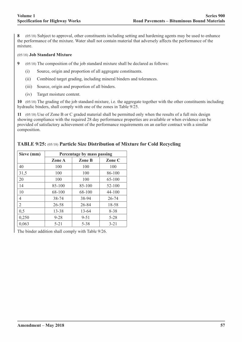
Volume 1 Series 900 Specification for Highway Works Road Pavements – Bituminous Bound Materials
Amendment – May 2018 57
8 (05/18) Subject to approval, other constituents including setting and hardening agents may be used to enhance the performance of the mixture. Water shall not contain material that adversely affects the performance of the mixture.
(05/18) Job Standard Mixture
9 (05/18) The composition of the job standard mixture shall be declared as follows:
(i) Source, origin and proportion of all aggregate constituents.
(ii) Combined target grading, including mineral binders and tolerances.
(iii) Source, origin and proportion of all binders.
(iv) Target moisture content.
10 (05/18) The grading of the job standard mixture, i.e. the aggregate together with the other constituents including hydraulic�binders,�shall�comply�with�one�of�the�zones�in�Table�9/25.
11 (05/18) Use of Zone B or C graded material shall be permitted only when the results of a full mix design showing compliance with the required 28 day performance properties are available or when evidence can be provided of satisfactory achievement of the performance requirements on an earlier contract with a similar composition.
TABLE 9/25: (05/18) Particle Size Distribution of Mixture for Cold Recycling
Sieve (mm) Percentage by mass passingZone A Zone B Zone C
40 100 100 10031,5 100 100 86-10020 100 100 65-10014 85-100 85-100 52-10010 68-100 68-100 44-1004 38-74 38-94 26-742 26-58 26-84 18-580,5 13-38 13-64 8-380,250 9-28 9-51 5-280,063 5-21 5-38 3-21
The binder addition shall comply with Table 9/26.

Volume 1 Series 900 Specification for Highway Works Road Pavements – Bituminous Bound Materials
58Amendment – May 2018
TABLE 9/26: (05/18) Minimum Binder Contents for Ex Situ Construction by Family and Binder Type
Family OPC Lime PFA GBS GGBS Bitumen*
QH 3% – – – – –
2% – 4% –
2% – 3% –
2% – 2% –
SH – 2% 8% – – –
– 2% 6% – –
2% – – 4%
– 1% – 10% – –
– – – 10% – –
QVE 1% – ** – – 3%
SVE – 1.5%*** ** – – 3%
* foamed or emulsion (residual) ** PFA may be added as filler ***lime may be added for ‘breaking’ and adhesion purposes, and, if PFA included as filler, will contribute to strength
(05/18) Mixture Design Validation
12 (05/18) When a mix design validation is required it shall be carried out on aggregates and binders representative of those to be used on the works. The validation may be carried out on CRBM mixed either in the laboratory or on a pilot basis on a full scale plant.
13 (05/18) The target mixture shall comply with sub-Clauses 5 and 6.
14 (05/18) A preliminary exercise shall be undertaken to establish a target grading and suitable moisture content.
15 (05/18) Representative samples of the mixture shall be taken and from these 150 mm diameter cylindrical specimens shall be produced in accordance with sub-Clause 14. These specimens shall be 150 mm high for hydraulic bound mixtures and 70-75 mm high for visco-elastic bound mixtures. The time between mixing and specimen production shall be in accordance with the setting times given in Table 9/29.
16 (05/18) The density of each specimen shall be measured and using the respective moisture content values, the dry density values shall be determined. The cylindrical specimens shall be conditioned and tested. The conditioning and testing regime shall be agreed with the Overseeing Organisation and the measured characteristics shall demonstrate compliance with the requirements of Table 9/27.
17 (05/18) The performance properties of the conditioned specimens shall be declared. The results shall be considered as indicative only, as the compliance criteria apply only to the specimens prepared during the execution of the works.
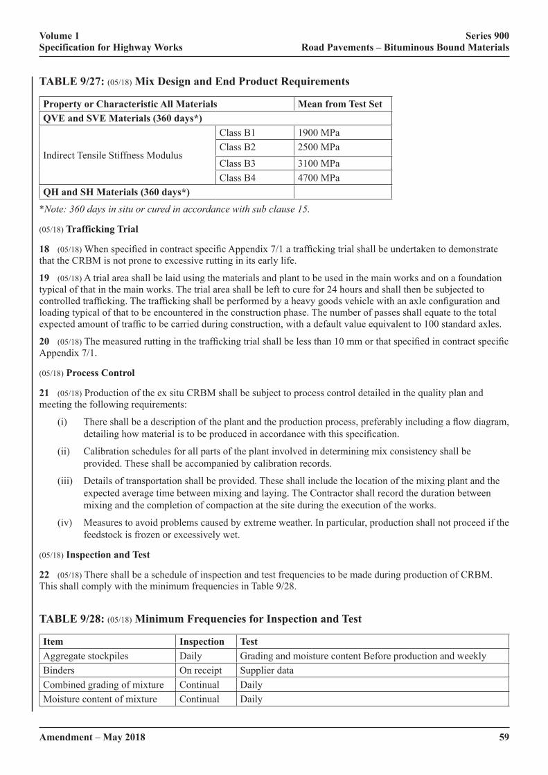
Volume 1 Series 900 Specification for Highway Works Road Pavements – Bituminous Bound Materials
Amendment – May 2018 59
TABLE 9/27: (05/18) Mix Design and End Product Requirements
Property or Characteristic All Materials Mean from Test SetQVE and SVE Materials (360 days*)
Indirect Tensile Stiffness Modulus
Class B1 1900 MPaClass B2 2500 MPaClass B3 3100 MPaClass B4 4700 MPa
QH and SH Materials (360 days*)
*Note: 360 days in situ or cured in accordance with sub clause 15.
(05/18) Trafficking Trial
18 (05/18)�When�specified�in�contract�specific�Appendix�7/1�a�trafficking�trial�shall�be�undertaken�to�demonstrate�that the CRBM is not prone to excessive rutting in its early life.
19 (05/18) A trial area shall be laid using the materials and plant to be used in the main works and on a foundation typical of that in the main works. The trial area shall be left to cure for 24 hours and shall then be subjected to controlled�trafficking.�The�trafficking�shall�be�performed�by�a�heavy�goods�vehicle�with�an�axle�configuration�and�loading typical of that to be encountered in the construction phase. The number of passes shall equate to the total expected�amount�of�traffic�to�be�carried�during�construction,�with�a�default�value�equivalent�to�100�standard�axles.
20 (05/18)�The�measured�rutting�in�the�trafficking�trial�shall�be�less�than�10�mm�or�that�specified�in�contract�specific�Appendix 7/1.
(05/18) Process Control
21 (05/18) Production of the ex situ CRBM shall be subject to process control detailed in the quality plan and meeting the following requirements:
(i)� There�shall�be�a�description�of�the�plant�and�the�production�process,�preferably�including�a�flow�diagram,�detailing�how�material�is�to�be�produced�in�accordance�with�this�specification.
(ii) Calibration schedules for all parts of the plant involved in determining mix consistency shall be provided. These shall be accompanied by calibration records.
(iii) Details of transportation shall be provided. These shall include the location of the mixing plant and the expected average time between mixing and laying. The Contractor shall record the duration between mixing and the completion of compaction at the site during the execution of the works.
(iv) Measures to avoid problems caused by extreme weather. In particular, production shall not proceed if the feedstock�is�frozen�or�excessively�wet.
(05/18) Inspection and Test
22 (05/18) There shall be a schedule of inspection and test frequencies to be made during production of CRBM. This shall comply with the minimum frequencies in Table 9/28.
TABLE 9/28: (05/18) Minimum Frequencies for Inspection and Test
Item Inspection TestAggregate stockpiles Daily Grading and moisture content Before production and weeklyBinders On receipt Supplier dataCombined grading of mixture Continual DailyMoisture content of mixture Continual Daily
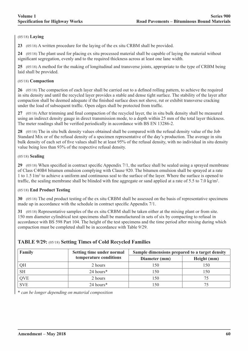
Volume 1 Series 900 Specification for Highway Works Road Pavements – Bituminous Bound Materials
60Amendment – May 2018
(05/18) Laying
23 (05/18) A written procedure for the laying of the ex situ CRBM shall be provided.
24 (05/18) The plant used for placing ex situ processed material shall be capable of laying the material without significant�segregation,�evenly�and�to�the�required�thickness�across�at�least�one�lane�width.
25 (05/18) A method for the making of longitudinal and transverse joints, appropriate to the type of CRBM being laid shall be provided.
(05/18) Compaction
26 (05/18)�The�compaction�of�each�layer�shall�be�carried�out�to�a�defined�rolling�pattern,�to�achieve�the�required�in situ density and until the recycled layer provides a stable and dense tight surface. The stability of the layer after compaction�shall�be�deemed�adequate�if�the�finished�surface�does�not�shove,�rut�or�exhibit�transverse�cracking�under�the�load�of�subsequent�traffic.�Open�edges�shall�be�protected�from�traffic.
27 (05/18)�After�trimming�and�final�compaction�of�the�recycled�layer,�the�in�situ�bulk�density�shall�be�measured�using an indirect density gauge in direct transmission mode, to a depth within 25 mm of the total layer thickness. The�meter�readings�shall�be�verified�periodically�in�accordance�with�BS�EN�13286-2.
28 (05/18)�The�in�situ�bulk�density�values�obtained�shall�be�compared�with�the�refusal�density�value�of�the�Job�Standard Mix or of the refusal density of a specimen representative of the day’s production. The average in situ bulk�density�of�each�set�of�five�values�shall�be�at�least�95%�of�the�refusal�density,�with�no�individual�in�situ�density�value being less than 93% of the respective refusal density.
(05/18) Sealing
29 (05/18)�When�specified�in�contract�specific�Appendix�7/1,�the�surface�shall�be�sealed�using�a�sprayed�membrane�of Class C40B4 bitumen emulsion complying with Clause 920. The bitumen emulsion shall be sprayed at a rate 1 to 1.5 l/m2 to achieve a uniform and continuous seal to the surface of the layer. Where the surface is opened to traffic,�the�sealing�membrane�shall�be�blinded�with�fine�aggregate�or�sand�applied�at�a�rate�of�5.5�to�7.0�kg/m2.
(05/18) End Product Testing
30 (05/18) The end product testing of the ex situ CRBM shall be assessed on the basis of representative specimens made�up�in�accordance�with�the�schedule�in�contract�specific�Appendix�7/1.
31 (05/18) Representative samples of the ex situ CRBM shall be taken either at the mixing plant or from site. 150 mm diameter cylindrical test specimens shall be manufactured in sets of six by compacting to refusal in accordance with BS 598 Part 104. The height of the test specimens and the time period after mixing during which compaction must be completed shall be in accordance with Table 9/29.
TABLE 9/29: (05/18) Setting Times of Cold Recycled Families
Family Setting time under normal temperature conditions
Sample dimensions prepared to a target densityDiameter (mm) Height (mm)
QH 2 hours 150 150SH 24 hours* 150 150QVE 2 hours 150 75SVE 24 hours* 150 75
* can be longer depending on material composition

Volume 1 Series 900 Specification for Highway Works Road Pavements – Bituminous Bound Materials
Amendment – May 2018 61
(05/18) Conditioning and Testing of Samples
32 (05/18) Prior to testing, specimens shall be conditioned in a controlled environment, sealed to keep the moisture in,�as�described�in�this�clause.�The�purpose�of�this�conditioning�is�to�simulate�the�likely�curing�over�the�first�year�in�the road.
33 (05/18) Immediately after compaction, the cylindrical specimens, in their moulds shall be double wrapped in cling-film�plastic�using�two�separate�sheets;�each�of�which�shall�be�sufficient�to�cover�the�entire�circumference�of�the�cylinder�and�the�two�ends�of�the�specimen.�Once�wrapped�in�cling-film�the�sample�shall�be�placed�in�a�sealed�plastic bag. Care shall be taken when handling the specimens not to damage the plastic bag or the underlying cling-�film�layer.�The�specimens�should�be�stored�in�air�or�water�at�a�temperature�within�2°C�of�the�nominal�conditioning temperature.
34 (05/18) The following conditioning regimes shall apply:
(i) QH specimens shall be conditioned for a period of 28 days at a temperature of 20+2°C.
(ii) SH and QVE specimens shall be conditioned for a period of 28 days at a temperature of 40+2°C.
(05/18) End Product Criteria
35 (05/18)�The�minimum�specification�compliance�criteria�for�the�process�control�tests�shall�be�as�described�in�Table 9/30.
TABLE 9/30: (05/18) End Product Criteria
Material property or characteristic Individual results Mean from test set of six specimensParticle�Size�Distribution Zone –Moisture content ±2% –Relative In situ density 93% minimum 95% minimumLayer thickness ±25�mm�of�specified ±15mm�of�specifiedIndirect Tensile Stiffness Modulus or Indirect Tensile Test
N/A Relevant value from Table 9/27 less 5%
In the event of test specimens failing to achieve the required indirect tensile test results, compliance shall be determined by the testing of cores extracted by dry coring after one year. The results shall be compared with the criteria in Table 9/27.
949 (05/18) Not Used
950 (05/18) Surface Preservation Systems
1 (05/18) Systems that are intended to extend the life of existing asphalt surfacing by the application of a proprietary�liquid�coating�shall�have�HAPAS�or�equivalent�product�acceptance�scheme�certification�to�demonstrate�their�performance.�Preservation�systems�without�HAPAS�or�equivalent�certification�shall�not�be�used�without�prior�approval by the Overseeing Organisation.
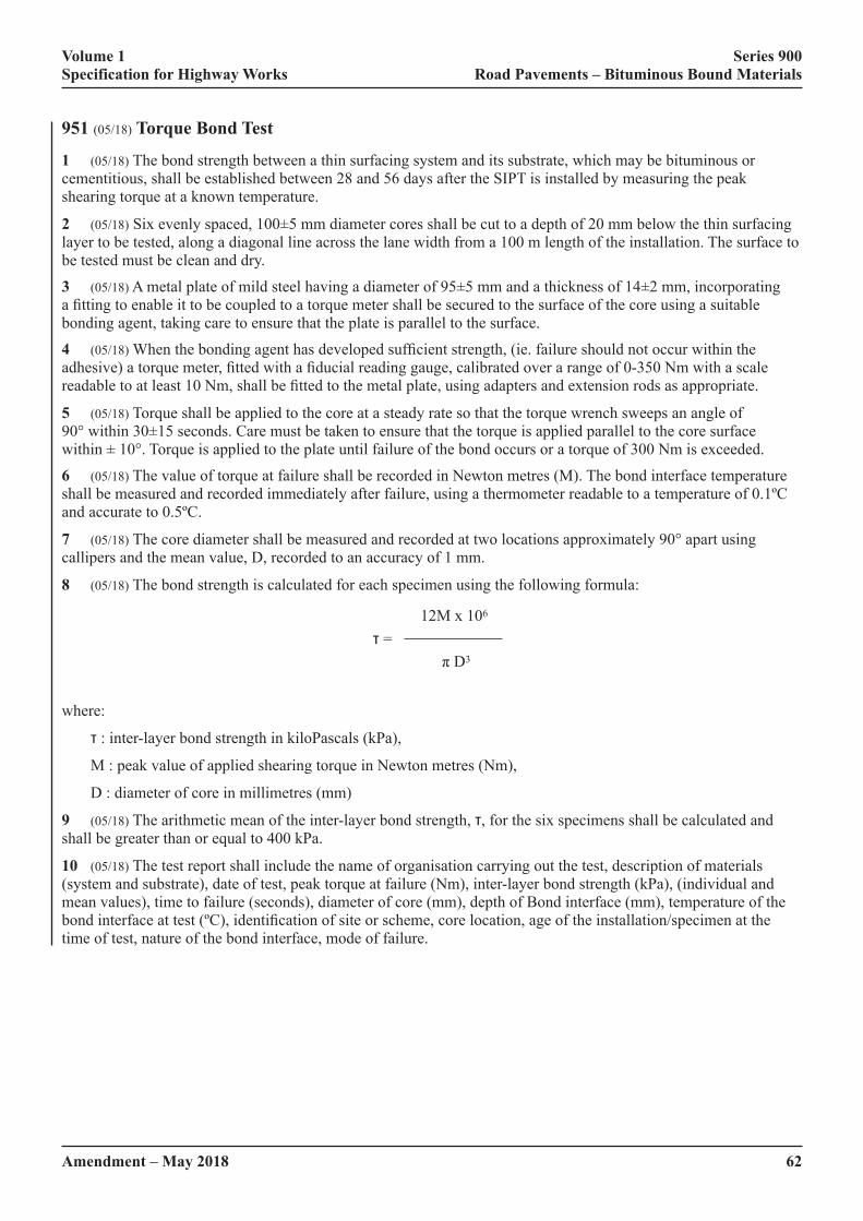
Volume 1 Series 900 Specification for Highway Works Road Pavements – Bituminous Bound Materials
62Amendment – May 2018
951 (05/18) Torque Bond Test
1 (05/18) The bond strength between a thin surfacing system and its substrate, which may be bituminous or cementitious, shall be established between 28 and 56 days after the SIPT is installed by measuring the peak shearing torque at a known temperature.
2 (05/18)�Six�evenly�spaced,�100±5�mm�diameter�cores�shall�be�cut�to�a�depth�of�20�mm�below�the�thin�surfacing�layer to be tested, along a diagonal line across the lane width from a 100 m length of the installation. The surface to be tested must be clean and dry.
3 (05/18)�A�metal�plate�of�mild�steel�having�a�diameter�of�95±5�mm�and�a�thickness�of�14±2�mm,�incorporating�a�fitting�to�enable�it�to�be�coupled�to�a�torque�meter�shall�be�secured�to�the�surface�of�the�core�using�a�suitable�bonding agent, taking care to ensure that the plate is parallel to the surface.
4 (05/18)�When�the�bonding�agent�has�developed�sufficient�strength,�(ie.�failure�should�not�occur�within�the�adhesive)�a�torque�meter,�fitted�with�a�fiducial�reading�gauge,�calibrated�over�a�range�of�0-350�Nm�with�a�scale�readable�to�at�least�10�Nm,�shall�be�fitted�to�the�metal�plate,�using�adapters�and�extension�rods�as�appropriate.
5 (05/18) Torque shall be applied to the core at a steady rate so that the torque wrench sweeps an angle of 90°�within�30±15�seconds.�Care�must�be�taken�to�ensure�that�the�torque�is�applied�parallel�to�the�core�surface�within�±�10°.�Torque�is�applied�to�the�plate�until�failure�of�the�bond�occurs�or�a�torque�of�300�Nm�is�exceeded.
6 (05/18) The value of torque at failure shall be recorded in Newton metres (M). The bond interface temperature shall be measured and recorded immediately after failure, using a thermometer readable to a temperature of 0.1ºC and accurate to 0.5ºC.
7 (05/18) The core diameter shall be measured and recorded at two locations approximately 90° apart using callipers and the mean value, D, recorded to an accuracy of 1 mm.
8 (05/18) The bond strength is calculated for each specimen using the following formula:
12M x 106
τ =
�π�D3
where:
τ : inter-layer bond strength in kiloPascals (kPa),
M : peak value of applied shearing torque in Newton metres (Nm),
D : diameter of core in millimetres (mm)
9 (05/18) The arithmetic mean of the inter-layer bond strength, τ, for the six specimens shall be calculated and shall be greater than or equal to 400 kPa.
10 (05/18) The test report shall include the name of organisation carrying out the test, description of materials (system and substrate), date of test, peak torque at failure (Nm), inter-layer bond strength (kPa), (individual and mean values), time to failure (seconds), diameter of core (mm), depth of Bond interface (mm), temperature of the bond�interface�at�test�(ºC),�identification�of�site�or�scheme,�core�location,�age�of�the�installation/specimen�at�the�time of test, nature of the bond interface, mode of failure.
Volume 1 Series 900 Specification for Highway Works Road Pavements – Bituminous Bound Materials
Amendment – May 2018 63
952 & 953 (05/18) Not used
954 (05/18) Method for Laboratory Determination of Interface Properties Using the Modified Leutner Shear Test
(05/18) Scope
1 (05/18)�This�Clause�specifies�a�laboratory�test�method�to�assess�the�bonding�between�adjacent�asphalt�pavement�layers using cylindrical samples. It is also appropriate for asphalt applied to concrete.
(05/18) Terms and Definitions
2 (05/18)�For�the�purposes�of�this�Clause�the�terms�and�definitions�given�in�BS�6100�shall�apply,�together�with�the�following:
(i) Peak Shear Stress: The maximum value of shear stress, determined as the maximum force divided by the initial cross sectional area of a specimen when tested as described in this Clause.
(ii) Displacement at Peak Shear Stress: The displacement at the maximum value of shear stress of a specimen when tested as described in this Clause.
(iii) Shear Stiffness Modulus: The peak shear stress divided by the displacement at the peak shear stress of a specimen when tested as described in this Clause.
(05/18) Principle of Test
3 (05/18) Cylindrical test specimens of nominal 150 mm diameter shall be subjected to direct shear loading at 20°C�using�the�modified�Leutner�shear�test.�The�maximum�shear�stress�(in�MPa)�at�the�interface�between�layers�shall be determined.
(05/18) Test Apparatus and Materials
4 (05/18) The following test apparatus and materials shall be used:
(i)� Shear�test�apparatus,�as�shown�in�Figure�9/2,�composed�of�a�base�body�(A)�on�which�are�fixed�the�sample support (B) and the lower shear ring (D). The upper shear ring (C) is attached to the upper body (E), which is movable along the guiding bars (F). The gap between shear rings (C and D) is 5 mm.
(ii)� Loading�frame�capable�of�achieving�a�constant�vertical�displacement�rate�of�50.0�±�2�mm�per�minute�and�a maximum load of at least 50kN.
(iii) Data logging system to record load and displacement during the test.
(iv) Metal extension, as shown in Figure 9/3.
(v)�� Stiff�adhesive,�such�as�epoxy�resin,�with�sufficient�strength�to�avoid�failure�within�the�adhesive�or�at�the�adhesive/asphalt material interface.
(05/18) Sample Preparation
5 (05/18)�Test�specimens�shall�be�cores�of�150�±�2�mm�diameter;�the�minimum�thickness�of�the�layers�above�and below the interface to be tested shall be 15 mm and 60 mm respectively. Specimens shall be cored from an in-service pavement or from a slab manufactured using a laboratory roller compactor in accordance with BS EN 12697-35 and BS EN 12697-33. If the thickness of the layer above the interface is between 15 and 30 mm, a metal extension shall be glued on top of the layer above the interface.
(05/18) Procedure
6 (05/18) The diameter and thickness of the specimen shall be determined to the nearest mm.

Volume 1 Series 900 Specification for Highway Works Road Pavements – Bituminous Bound Materials
64Amendment – May 2018
7 (05/18) The specimen shall be placed into a suitable temperature controlled conditioning environment at 20 ± 0.5°C for a minimum of 5 hours.
8 (05/18)�The�appropriate�shear�rings,�to�form�a�loose�fit�around�the�specimen�(for�example,�151�mm�diameter�shear rings for a 150 mm diameter specimen), shall be selected and attached to the Leutner test frame.
9 (05/18) The specimen shall be placed into the test apparatus and the interface aligned, (Figure 9/2 (G)), between the upper and lower shear rings (Figure 9/2 (C and D)). If a metal extension is used, the specimen shall be placed into the test apparatus so that the direction of the grooves is perpendicular to the direction of the applied shear load.
10 (05/18) Tighten the sample support using a suitable spanner.
11 (05/18) The test apparatus shall be placed into the loading frame and adjusted until the upper shear ring (Figure 9/2 (C)) nearly touches the specimen.
12 (05/18) Start the data logging system (to record load and displacement) and commence shear loading. The loading�rate�shall�be�50.0�±�2�mm�per�minute.
13 (05/18)�Record�the�load�(F)�to�the�nearest�0.1�kN�and�the�displacement�(δ)�to�the�nearest�0.1�mm.
14 (05/18) Stop the shear loading when the test frame reaches its limit of 7 mm displacement. The length of time between removal of the specimen from the temperature controlled conditioning environment and completion of testing shall not exceed 15 minutes.
15 (05/18) After the test has been completed, the apparatus shall be dismantled and the specimen removed.
16 (05/18) Both sections of the specimen shall be observed (especially the interface) for any visual cracks and unusual appearance (i.e. crushed aggregates on edges). Record any comments as necessary.
(05/18) Calculation and Expression of Results
17 (05/18) Calculate the shear stress as follows:
Where:
τ� =� shear�stress�in�(MPa)
F = load (in kN)
r = initial radius of specimen (in mm)
18 (05/18) Produce a shear stress versus shear displacement graph (an example is shown in Figure 9/4) using the recorded data.
19 (05/18) Determine the following parameters from the graph:
(i)� τ�max = peak shear stress, MPa, expressed to the nearest 0.1
(ii)� δ�max = displacement at peak shear stress, mm, expressed to the nearest 0.1
(iii)� k� =�shear�stiffness�modulus�=�τ�max/�δ�max, MPa/mm, expressed to the nearest 0.1
(05/18) Test Report
20 (05/18) The test report shall contain not less than the following information:
(i) A reference to this test method and test conditions.
(ii) Material descriptions for both layers.
(iii) Type and amount of tack (bond) coat (if known).

Volume 1 Series 900 Specification for Highway Works Road Pavements – Bituminous Bound Materials
Amendment – May 2018 65
(iv) For each specimen tested, report:
– specimen diameter, expressed to the nearest mm
– layer thicknesses, expressed to the nearest mm
– maximum load (F), expressed to the nearest 0.1 kN
–� peak�shear�stress�(τ�max), expressed to the nearest 0.1 MPa
–� displacement�at�peak�shear�stress(δ�max), expressed to the nearest 0.1 mm
– shear stiffness modulus (k), expressed to the nearest 0.1 MPa/mm
– any cracks or other damage.
(v) The test temperature, expressed to the nearest 0.5°C
(vi) The use (or otherwise) of a metal extension.
A – base body B – sample support C – upper shear ring D – lower shear ring E – upper body F – guiding bar G – specimen interface
FIGURE 9/2: (05/18) Schematic Diagram of the Modified Leutner Shear Test apparatus
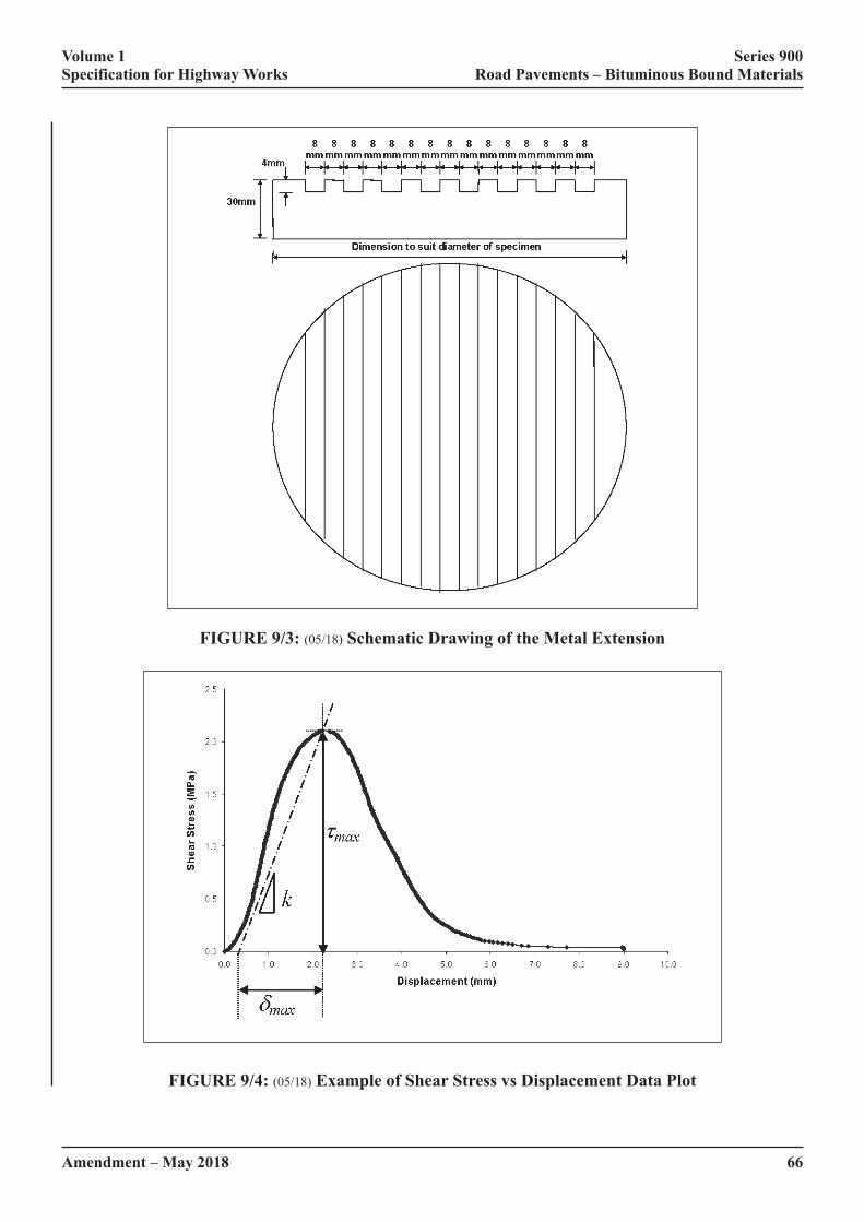
Volume 1 Series 900 Specification for Highway Works Road Pavements – Bituminous Bound Materials
66Amendment – May 2018
FIGURE 9/3: (05/18) Schematic Drawing of the Metal Extension
FIGURE 9/4: (05/18) Example of Shear Stress vs Displacement Data Plot

Volume 1 Series 900 Specification for Highway Works Road Pavements – Bituminous Bound Materials
Amendment – May 2018 67
955 (05/18) Ageing Profile Test Using a Modified Rolling Thin Film Oven Test (MRTFOT)
(05/18) Scope
1 (05/18)�This�Clause�specifies�the�procedure�for�obtaining�samples�of�‘Aged�Binder’�after�various�stages�of�conditioning.�In�this�way,�a�plot�of�binder�properties�providing�an�‘Ageing�Profile’�may�be�accomplished�in�a�short�time�using�the�Modified�Rolling�Thin�Film�Oven�Test�(MRTFOT)�to�simulate�ageing�in�road�materials�over�many�years in service.
The�MRTFOT�utilises�the�Rolling�Thin�Film�Oven�(ASTM�2872)�specified�in�BS�EN�12607-1.
The method is suitable for generating small quantities of binder for rheological testing
The�‘Ageing�Profile’�is�generated�by�determining�the�rheological�properties�of�complex�shear�(stiffness)�modulus�G*�and�phase�angle�δ�of�samples�taken�from�the�oven�at�intervals�throughout�the�test�period,�typically�one�day.�Other properties such as durability of cohesion may also be assessed.
Three protocols are used depending on the type of binder and its use:
(i)� a�method�to�simulate�ageing�of�polymer�modified�binder�or�paving�grade�bitumen�used�in�the�manufacture of asphalt;
(ii)� a�method�to�remove�the�water�phase�and�volatile�flux�from�polymer�modified�bituminous�emulsions�and�simulate ageing and;
(iii) a method to test the potential for preservatives to reduce the ageing rate of bitumen.
The�‘Ageing�Profile’�in�terms�of�rheological�characteristics�provides�‘Product�Identification’�and�this�is�essential�to�ensure�consistency�and�to�enable�proprietary�binders�to�be�identified.
(05/18) Warning
2 (05/18)�The�use�of�this�test�method�can�involve�hazardous�materials,�operations�and�equipment.�This�Clause�does not purport to address all of the safety problems associated with the use of the test method. It is the responsibility of the user of these test methods to establish appropriate safety and health practices and determine the applicability of regulatory limitations prior to use.
(05/18) Asphalt Binders
3 (05/18)�Binders�used�to�manufacture�hot�mixed�asphalt�(asphalt�binders)�are�first�subjected�to�a�‘Short-term�Ageing Test’ to simulate the effects of manufacture, transport and laying. In this respect, the test described in this Clause has been shown to be equivalent to BS EN 12607-1. The binder is continually stirred by rotating stainless steel�screws�in�sample�cans�to�obtain�a�homogeneous�sample;�the�procedure�also�benefits�from�a�faster�oxidation�rate (rapid ageing), because of the increased exposure to the jetted air stream and, therefore, a shorter test duration.
The binder samples are then aged at a lower temperature and samples removed at intervals and tested to obtain an ‘Ageing�Profile’.�This�is�particularly�useful�for�asphalt,�because�different�air�void�contents�and�binder�contents�in�a�road pavement result in different ageing rates.
The ‘Long-term Aged’ binder sample, where the characteristics are equivalent to those obtained after 65 hours using the Pressure Ageing Vessel PAV85 Test, is obtained after 7 hours; therefore, the test may be carried out in one day. PAV85 is detailed in BS EN 14769.
Binders used for manufacturing ‘Warm Asphalt’ are mixed at much lower temperatures than for hot mixed asphalt and they do not need the same high temperature protocol for ‘Short-term Ageing’; this part of the procedure is therefore amended for these binders. All the ageing is done at the lower temperature.
Volume 1 Series 900 Specification for Highway Works Road Pavements – Bituminous Bound Materials
68Amendment – May 2018
(05/18) Bituminous Emulsion Binders
4 (05/18)�Bitumen�and�polymer�modified�bituminous�emulsions�are�first�subjected�to�a�‘Rapid�Recovery�Test’�which removes any water phase and volatile oils to produce a ‘Recovered Binder’. The ‘Recovered Binder’ has similar properties to that produced from other evaporative tests, but is achieved over a shorter period and the use of nitrogen, replacing air, reduces risks associated with volatile oils in the oven. The ‘Recovered Binder’ in rheological terms is equivalent to that recovered using BS EN 13074-1.
The�‘Ageing�Profile’�is�provided�by�continuing�the�ageing�of�the�‘Recovered�Binder’�in�the�MRTFO�at�a�higher�temperature,�replacing�the�nitrogen�gas�with�air�and�removing�samples�after�specified�periods�for�testing.�A�‘Stabilised Binder’, equivalent in rheological terms to that produced using BS EN 13074-2, may be obtained from the�‘Ageing�Profile’�Plot�for�a�particular�emulsion.�Fluxed�and�vegetal�fluxed�binders�where�volatile�oils�are�thought�to be present may also be tested using this protocol.
(05/18) Preservatives
5 (05/18) 40/60 penetration grade bitumen, used as a control, is subjected to ‘Short-term Ageing’ in the MRTFOT followed by an extended period at a lower temperature to simulate the ageing of the bitumen in a road pavement. This aged bitumen control is then cooled to ambient and treated with the preservative. Most of the volatile oils are then removed by conditioning the samples in the MRTFOT using a nitrogen blanket. The aged bitumen, treated by preservative, is then subjected to further ageing with the MRTFOT. The properties of the aged bitumen, after action of�the�preservative,�are�assessed�by�an�‘Ageing�Profile’�using�rheology�and�compared�with�the�‘Ageing�Profile’�of�the control bitumen.
(05/18) Definitions
6 (05/18)�For�the�purposes�of�the�procedures�specified�in�this�Clause�the�following�definitions�apply:
(i) Laboratory Sample: sample of bituminous binder intended for laboratory tests. It may be a spot sample, a composite sample or a part thereof (a divided sample) as described in BS EN 58.
(ii) Test Sample: sample of bituminous binder produced by treatment or subdivision of a laboratory sample for individual test (BS EN 58).
(iii) Recovered Binder:�material�remaining�after�removal�of�water�or�flux�from�a�polymer�modified�or�unmodified�bituminous�emulsion�or�fluxed�binder�in�the�presence�of�nitrogen,�equivalent�to�the�recovered binder using BS EN 13074-1.
(iv) Aged Binder: material remaining after the Ageing protocol.
(v) Short-term Aged Binder: material obtained during the MRTFOT which is equivalent to that provided by BS EN 12607-1(RTFOT)
(vi) Long-term Aged Binder: material obtained during the MRTFOT which is equivalent to that provided by BS EN 14769
(vii) Ageing Profile: graphical plot of performance-related results from samples tested during the ageing protocol of this method. Performance-related testing is carried out using a Dynamic Shear Rheometer (DSR), providing G* and phase angle data at a determined temperature and frequency.
(05/18) Test Apparatus (common to all protocols)
7 (05/18) The following test apparatus shall be used:
(i) RTFOT apparatus to BS EN 12607-1.
(ii)� Eight�identifiable�sample�cans�with�threaded�screw�top�lids�(or�other�fixing�system)�manufactured�from�aluminium�and�coated�on�all�internal�surfaces�with�polytetrafluoroethylene�(PTFE)�with�internal�dimensions and aperture diameter (L2) as shown below:

Volume 1 Series 900 Specification for Highway Works Road Pavements – Bituminous Bound Materials
Amendment – May 2018 69
The�taper�in�the�throat�(from�L2�aperture�to�lid�top)�is�45�±�5°
FIGURE 9/5: (05/18) Sample Can and Lid (both with threads)
(iii) Eight screws manufactured from high quality stainless steel (surgical quality) complying with BS EN�10088-3,�designation�1.4404�to�a�‘fine�machined�finish’.�All�screws�shall�have�dimensions:�diameter�12.2�±�0.2mm,�length�120�±�0.5mm�and�have�between�18�and�19�turns�with�a�pitch�of�6�±�0.2mm.�The�depth�of�cut�shall�be�2�±�0.2mm�with�a�semi-circular�profile�–�see�Figure�9/6.�At�one�end,�the�screw�shall�have�an�unthreaded�shank�10�±0.5mm�long�and�7.5�±�0.5mm�diameter,�ending�in�a�45°�cone,�truncated�to�give�a�flat�end�at�the�apex�1.5�to�2.0mm�diameter.�The�minimum�weight�of�a�screw�shall�be�70g.�The direction of screw shall be such that the binder sample is drawn to the closed end of the sample can bottle when the can containing the screw is rotated in the carousel. If the RTFO carousel rotates anticlockwise, viewed from the front, screws with a right-hand thread are required and if the carousel rotates clockwise, screws with a left hand thread are required.

Volume 1 Series 900 Specification for Highway Works Road Pavements – Bituminous Bound Materials
70Amendment – May 2018
Dimension a = 1.5mm to 2mm
FIGURE 9/6 (05/18) Screw with Right-handed Thread (for anti-clockwise rotating carousel)
(iv)� A�spatula�for�removing�the�binder�from�the�sample�cans�(a�flat�blade�with�a�square�end�has�been�found�suitable).
(v) A balance accurate to 0.05g.
(vi)� A�timer�capable�of�timing�100�minutes,�accurate�to�1�second�in�five�minutes�and,�for�the�MRTFOT,�a�timer capable of timing 25 hours to the same accuracy.
(vii) Nitrogen gas supply (for Rapid Recovery Test and preservative test).
(viii) Air supply, clean dry air (for MRTFOT).
(ix) An oven to pre-heat the sample cans and the binder to the required temperature.
(05/18) Principle of the Ageing Profile Test for Polymer Modified and Unmodified Bituminous Binders for Asphalts
8 (05/18)�A�thin�film�of�binder�is�rotated�in�aluminium�sample�cans�with�screw�top�lids,�both�coated�internally�with PTFE (replacing glass bottles), using the Rolling Thin Film Oven Test (RTFOT) apparatus, as described in BS EN 12607-1. Special screws are used to disturb the binder and maintain a homogenous material during ‘Ageing’.�Air�is�jetted�over�the�film�of�binder�for�a�much�longer�period�than�in�the�conventional�test�and�a�lower�temperature used in order to simulate the ‘ageing’ of the binder in the road after application. The screws accelerate the�process,�and�are�necessary�to�maintain�a�homogeneous�sample,�especially�when�testing�polymer�modified�binders, which tend to form a skin and may phase separate in static ageing tests.
The initial conditioning test is to simulate the changes to the properties of the binder caused by the high temperatures during manufacture, transport and laying, termed ‘Short-term Ageing’.
Further ageing is carried out at a reduced temperature and samples removed after set periods and tested, so that an ‘Ageing�Profile’�may�be�plotted.
(05/18) Test Procedure for Determining the Ageing Profile of Hot Mixed Polymer Modified and Unmodified Bituminous Binders for Asphalts
9 (05/18) Obtain a sample in accordance with BS EN 58. Stir the sample thoroughly to ensure it is completely homogenized.�If�sub-samples�are�taken�these�shall�have�a�minimum�volume�of�250ml.�Ensure�that�the�RTFO�is�level�so�that�the�horizontal�axes�of�the�sample�cans�when�in�position�in�the�carousel�are�level.�Pre-heat�the�oven�to�

Volume 1 Series 900 Specification for Highway Works Road Pavements – Bituminous Bound Materials
Amendment – May 2018 71
163�±�1°C,�1h�is�generally�sufficient.�For�binders�used�to�manufacture�warm�mixed�asphalts,�substitute�135°C�for�163°C throughout the test procedure.
Insert a stainless steel screw into each of the sample cans with the tapered end of the screw towards the aperture of the container and record the mass of each assembly to 0.1g. Heat the sample cans and the stainless steel screws to 163�±�1°C�for�90�±�10�min.
Heat�the�sample�to�170�±�3°C.�Thoroughly�stir�the�sample�to�ensure�homogeneity�immediately�prior�to�decanting�into the sample cans.
Pour�19.0�±�0.5g�of�the�sample�into�a�preheated�sample�can�and�record�the�mass�with�lid.�Immediately�after�weighing, roll the sample cans to ensure distribution of the binder on the walls of the can.
Mount the sample can in the carousel of the RTFO. Repeat for the remaining sample cans. Close the door of the RTFO�between�mounting�each�sample�can�in�the�carousel.�The�period�between�weighing�the�first�sample�can�with�binder and mounting of all the sample cans and the start of the rotation of the carousel shall not exceed 20 minutes.
When�the�carousel�is�fully�loaded,�rotate�the�carriage�assembly�at�a�speed�of�15.0�±�0.2min-1.�Start�the�flow�of�air�at�a�set�rate�of�4000�±�200ml/min.�Start�the�timer.�Maintain�the�samples�in�the�oven�and�the�air�flowing�for�45�±�1min�from�the�time�the�test�temperature�reaches�163�±�1°C.
If�the�test�temperature�of�163°C�is�not�reached�within�the�first�15�minutes,�discontinue�the�test.
After�45�±�1min,�sample�cans�(minimum�2)�may�be�removed�for�testing�and�to�determine�mass�loss,�if�required.�This is the Short-term Aged binder, equivalent to RTFOT, BS EN 12607-1.
To�continue�the�Ageing�Profile�test,�maintain�the�temperature�at�163°C�for�a�further�15�minutes,�with�the�carousel�rotating�in�the�air�flow,�then�reduce�the�temperature�of�the�oven�to�135�±�1°C.�Note�the�time�the�RTFO�takes�to�reach 135°C. Once the temperature has been achieved, continue to rotate the samples in the air supply and remove sample cans to obtain samples of aged binder as required for testing after three periods:
2h�±�10min;�termed�Aged2 Binder
4h�±�10min;�termed�Aged4 Binder
6h�±�10min;�termed�Aged6 Binder: this is the Long-term Aged Binder, equivalent to PAV85.
Other periods may be used either for convenience or to allow other degrees of ageing to be investigated.
TABLE 9/31 (05/18) Summary of Sampling Times
Stage Gas RTFO Temperature
Time Sampling Cumulative time
Ageing
Air 163°C 45min RTFOT Equivalent 45minsAir 163°C 15min None 1h 00minAir 135°C 2h Aged2 test samples 3h 00minAir 135°C 4h Aged4 test samples 5h 00minAir 135°C 6h Aged6 test samples (equivalent to PAV85) 7h 00min
For binders used to manufacture ‘Warm Asphalt’, ‘Short Term Ageing’ at 163°C is not required, therefore, replace 163ºC by 135ºC in Table 9/31 and report in addition Aged1 result (ageing at 135°C after a cumulative time of 1h�±�5min).
(05/18) Handling of the Aged Binder
10 (05/18) If the binder is to be tested immediately, remove a sample can from the carousel, extract the screw using a small spatula and set the screw aside for cleaning. Place the sample can(s) in an oven preheated to the softening point�of�the�binder�plus�100°C�(if�known),�or�170°C�if�the�properties�of�the�binder�are�unknown,�for�20�±�5min.
Volume 1 Series 900 Specification for Highway Works Road Pavements – Bituminous Bound Materials
72Amendment – May 2018
Place the containers on their sides in an oven. This allows the binder to drain to one side of the container, which is more easily removed with the spatula.
At�the�end�of�20�±�5min,�remove�the�sample�can�from�the�oven,�unscrew�the�lid�and,�using�the�spatula,�scrape�the�aged binder from the sample can and prepare the test samples in accordance with the relevant test method. Warming the spatula to the same temperature as the binder facilitates removal of the binder.
If the aged binder from more than one sample can is needed to produce a test sample, combine the aged binder from the sample cans and re-heat. Re-heating for testing shall be in accordance with BS EN 12594, ensuring that aged�binder�is�heated�for�no�longer�than�is�absolutely�necessary.�The�binder�shall�be�thoroughly�homogenized�by�stirring after heating and before being used for testing, while taking care not to entrain any air.
If the binder is not to be tested immediately, remove a sample can from the RTFO, extract the screw using a small spatula and set the screw aside for cleaning. Unscrew the lid and, using the spatula, scrape the aged binder from the sample can and place on a silicon sheet. The binder shall be sealed and stored at between 0°C to 5°C. The sample shall be re-heated in accordance with BS EN 12594 and homogenised immediately before testing.
If the aged samples are to be transferred to another laboratory for testing, they shall not be subjected to temperatures greater than ambient after ageing and before testing, and the delay before testing shall not exceed 120 hours.
The thermal history of the sample shall be recorded.
(05/18) Principle of the Ageing Profile Test for Polymer Modified or Unmodified Bituminous Emulsions or Fluxed Binders
11 (05/18)�A�thin�film�of�binder�is�rotated�in�aluminium�sample�cans�with�screw�top�lids,�both�coated�internally�with�PTFE (replacing glass bottles), using the RTFOT apparatus, as described in BS EN 12607-1, to evaporate water from�bituminous�emulsions�and/or�the�light�solvent�or�highly�volatile�fraction�from�fluxed�or�other�binders.�Special�screws are used to disturb the binder and maintain a homogenous material during breaking and/or curing. Nitrogen gas�instead�of�air�is�jetted�over�the�film�of�bituminous�binder�at�a�lower�temperature�in�order�to�minimize�ageing�effects�and�simulate�the�condition�of�the�binder�soon�after�application.�The�first�part�of�the�process�is�carried�out�with the RTFO set at 85°C to prevent frothing of the binder. The temperature is then increased to 135°C to drive off any remaining water and/or solvent to provide the ‘Recovered Binder’, which is equivalent to the recovered binder obtained�from�BS�EN�13074-1.�The�‘Ageing�Profile’�is�provided�by�continuing�the�ageing�of�the�binder�in�the�RTFO�at�135°C,�replacing�the�nitrogen�gas�with�air�and�removing�samples�after�specified�periods�for�testing.
(05/18) Test Procedure for Recovery and Ageing of Bituminous Emulsion and Fluxed Binders
12 (05/18) Obtain a sample in accordance with BS EN 58. Stir the sample thoroughly to ensure it is completely homogenized.�The�temperature�of�the�binder�sample�shall�not�be�less�than�70%�of�the�normal�application�temperature in degrees Celsius and shall be recorded (for example, high binder content surface dressing emulsion may�require�a�minimum�of�60°C,�or�a�polymer�modified�fluxed�binder,�130°C).�The�sample�history�if�known�shall�be recorded; this is important, as some ageing may have occurred. If sub-samples are taken these shall have a minimum�volume�of�250ml.�Ensure�that�the�oven�is�level�so�that�the�horizontal�axes�of�the�sample�cans,�when�in�position�in�the�carriage,�are�level.�Pre-heat�the�oven�to�85�±�1°C,�1h�is�generally�sufficient.
Insert a stainless steel screw into each of the sample cans with the tapered end of the screw towards the aperture of the container and record the mass of each assembly to 0.1g. Heat the sample cans, lids and the stainless steel screws to�85�±�1°C�for�90�±�10min.
Heat�the�sample�to�the�application�temperature�of�the�binder,�or,�if�this�is�not�known,�to�60�±�3°C.�Thoroughly�stir�the sample to ensure homogeneity immediately prior to decanting into the sample cans, taking care to minimise loss of water content and/or any volatile oil. Some cut-back binders and other binders such as primers having low flash�points�are�not�suitable�for�this�test.�If�there�is�any�doubt�concerning�the�volatile�nature�of�the�sample�for�test,�a�suitable�flash�point�test�must�be�carried�out�before�proceeding�with�the�‘Ageing�Profile�test’�or�heating�to�60°C.
Pour�19.0�±�0.5g�of�the�sample�into�a�preheated�sample�can�and�record�the�mass.�Immediately�after�weighing,�roll�the containers to ensure distribution of the binder round the bottle.
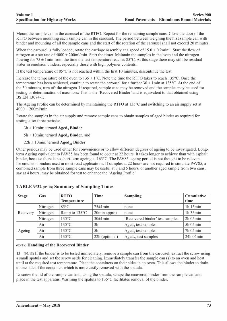
Volume 1 Series 900 Specification for Highway Works Road Pavements – Bituminous Bound Materials
Amendment – May 2018 73
Mount the sample can in the carousel of the RTFO. Repeat for the remaining sample cans. Close the door of the RTFO�between�mounting�each�sample�can�in�the�carousel.�The�period�between�weighing�the�first�sample�can�with�binder and mounting of all the sample cans and the start of the rotation of the carousel shall not exceed 20 minutes.
When�the�carousel�is�fully�loaded,�rotate�the�carriage�assembly�at�a�speed�of�15.0�±�0.2min-1.�Start�the�flow�of�nitrogen�at�a�set�rate�of�4000�±�200ml/min.�Start�the�timer.�Maintain�the�samples�in�the�oven�and�the�nitrogen�flowing�for�75�±�1min�from�the�time�the�test�temperature�reaches�85°C.�At�this�stage�there�may�still�be�residual�water in emulsion binders, especially those with high polymer contents.
If�the�test�temperature�of�85°C�is�not�reached�within�the�first�10�minutes,�discontinue�the�test.
Increase�the�temperature�of�the�oven�to�135�±�1°C.�Note�the�time�the�RTFO�takes�to�reach�135°C.�Once�the�temperature�has�been�achieved,�continue�to�rotate�the�carousel�for�a�further�30�±�1min�at�135°C.�At�the�end�of�the 30 minutes, turn off the nitrogen. If required, sample cans may be removed and the samples may be used for testing or determination of mass loss. This is the ‘Recovered Binder’ and is equivalent to that obtained using BS EN 13074-1.
The�Ageing�Profile�can�be�determined�by�maintaining�the�RTFO�at�135°C�and�switching�to�an�air�supply�set�at�4000�±�200ml/min.
Rotate the samples in the air supply and remove sample cans to obtain samples of aged binder as required for testing after three periods:
3h�±�10min;�termed�Aged3 Binder
5h�±�10min;�termed�Aged5 Binder, and
22h�±�10min,�termed�Aged22 BinderOther periods may be used either for convenience or to allow different degrees of ageing to be investigated. Long-term Ageing equivalent to PAV85 has been found to occur at 22 hours. It takes longer to achieve than with asphalt binder, because there is no short-term ageing at 163°C. The PAV85 ageing period is not thought to be relevant for emulsion binders used in most road applications. If samples at 22 hours are not required to simulate PAV85, a combined sample from three sample cans may be useful at 3 and 5 hours, or another aged sample from two cans, say�at�4�hours,�may�be�obtained�for�test�to�enhance�the�‘Ageing�Profile’
TABLE 9/32 (05/18) Summary of Sampling Times
Stage Gas RTFO Temperature
Time Sampling Cumulative time
RecoveryNitrogen 85°C 75±1min none 1h 15minNitrogen Ramp to 135°C 20min approx none 1h 35minNitrogen 135°C 30±1min ‘Recovered binder’ test samples 2h 05min
AgeingAir 135°C 3h Aged3 test samples 5h 05minAir 135°C 5h Aged5 test samples 7h 05minAir 135°C 22h (optional) Aged22 test samples 24h 05min
(05/18) Handling of the Recovered Binder
13 (05/18) If the binder is to be tested immediately, remove a sample can from the carousel, extract the screw using a small spatula and set the screw aside for cleaning. Immediately transfer the sample can (s) to an oven and heat until at the required test temperature. Place the containers on their sides in an oven. This allows the binder to drain to one side of the container, which is more easily removed with the spatula.
Unscrew the lid of the sample can and, using the spatula, scrape the recovered binder from the sample can and place in the test apparatus. Warming the spatula to 135°C facilitates removal of the binder.

Volume 1 Series 900 Specification for Highway Works Road Pavements – Bituminous Bound Materials
74Amendment – May 2018
If the recovered binder from more than one sample can is needed to produce a test sample, combine the recovered binder from the sample cans and re-heat. Re-heating for testing shall be in accordance with BS EN 12594, ensuring that recovered binder is heated for no longer than is absolutely necessary. The recovered binder shall be thoroughly homogenized�by�stirring�after�heating�and�before�being�used�for�testing,�while�taking�care�not�to�entrain�any�air.
If the recovered binder is not to be tested immediately, remove a sample can from the RTFO, extract the screw using a small spatula and set the screw aside for cleaning. Unscrew the lid and, using the spatula, scrape the recovered binder from the sample can and place on a silicon sheet. The binder shall be sealed and stored at between 0°C to 5°C. The sample shall be re-heated in accordance with BS EN 12594 and homogenised immediately before testing.
If the recovered samples are to be transferred to another laboratory for testing, they shall not be subjected to temperatures greater than ambient after recovery and before testing, and the delay before testing shall not exceed 120 hours.
The thermal history of the sample shall be recorded.
(05/18) Handling of the Aged Binder
14 (05/18) If the binder is to be tested immediately, remove a sample can from the carousel, extract the screw using a small spatula and set the screw aside for cleaning. Place the sample can (s) in an oven preheated to the softening point�of�the�binder�plus�100°C�(if�known),�or�170°C�if�the�properties�of�the�binder�are�unknown,�for�20�±�5min.�Place the sample cans on their sides in an oven. This allows the binder to drain to one side of the sample can, which is more easily removed with the spatula.
At�the�end�of�20�±�5min,�remove�the�sample�can�from�the�oven,�unscrew�the�lid�and,�using�the�spatula,�scrape�the�aged binder from the sample can and prepare the test samples in accordance with the relevant test method. Warming the spatula to the same temperature as the binder facilitates removal of the binder.
If the aged binder from more than one sample can is needed to produce a test sample, combine the aged binder from the containers and re-heat. Re-heating for testing shall be in accordance with BS EN 12594, ensuring that aged�binder�is�heated�for�no�longer�than�is�absolutely�necessary.�The�binder�shall�be�thoroughly�homogenized�by�stirring after heating and before being used for testing, while taking care not to entrain any air.
If the binder is not to be tested immediately, remove a sample can from the RTFO, extract the screw using a small spatula, and set the screw aside for cleaning. Unscrew the lid and, using the spatula, scrape the aged binder from the sample can and place on a silicon sheet. The binder shall be sealed and stored at between 0°C to 5°C. The sample shall be re-heated in accordance with BS EN 12594 and homogenised immediately before testing.
If the aged samples are to be transferred to another laboratory for testing, they shall not be subjected to temperatures greater than ambient after ageing and before testing, and the delay before testing shall not exceed 120 hours.
The thermal history of the sample shall be recorded.
(05/18) Principle of Assessing the Action of Preservatives using the MRTFOT
15 (05/18)�A�thin�film�of�40/60�penetration�grade�binder�is�rotated�in�aluminium�sample�cans,�coated�internally�with PTFE (replacing glass bottles), using the Rolling Thin Film Oven Test (RTFOT) apparatus, as described in BS EN 12607-1. Special screws are used to disturb the binder and maintain a homogenous material during conditioning. The bitumen is subjected to ‘Short-term Ageing’ followed by an extended period in the RTFO to simulate the ageing of the bitumen in a road pavement. The properties of the ‘Long-term Aged’ bitumen may be determined at this stage. The aged bitumen control in the remaining samples is then cooled to ambient, treated with the preservative and left for 24 hours. Most of the remaining highly volatile oils are subsequently removed by conditioning the samples in the RTFO using a nitrogen blanket. The aged bitumen, treated by preservative, is then�subjected�to�further�ageing�with�the�Modified�RTFO.�The�properties�of�the�aged�bitumen,�after�action�of�the�preservative,�are�assessed�by�an�‘Ageing�Profile’�test,�using�rheology�values�of�complex�shear�(stiffness)�modulus�G*�and�phase�angle�δ,�in�accordance�with�BS�EN�14770.�Cohesion�durability�may�also�be�determined.
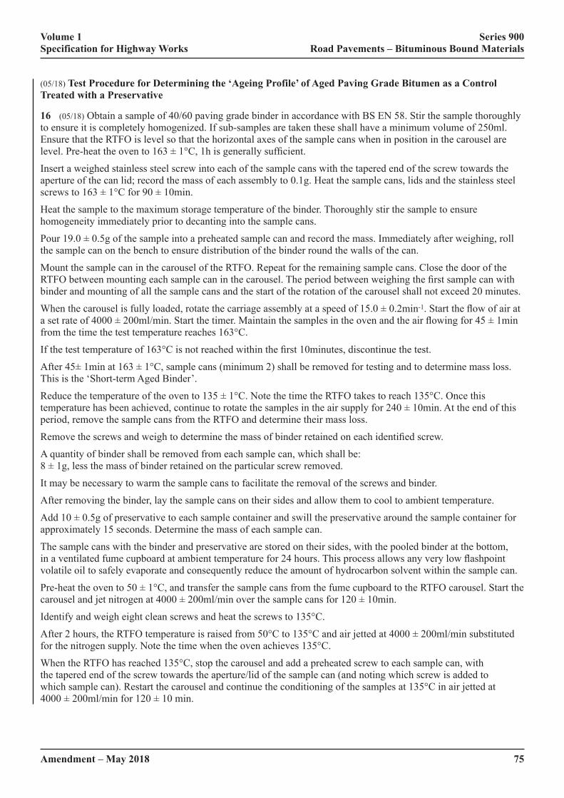
Volume 1 Series 900 Specification for Highway Works Road Pavements – Bituminous Bound Materials
Amendment – May 2018 75
(05/18) Test Procedure for Determining the ‘Ageing Profile’ of Aged Paving Grade Bitumen as a Control Treated with a Preservative
16 (05/18) Obtain a sample of 40/60 paving grade binder in accordance with BS EN 58. Stir the sample thoroughly to�ensure�it�is�completely�homogenized.�If�sub-samples�are�taken�these�shall�have�a�minimum�volume�of�250ml.�Ensure�that�the�RTFO�is�level�so�that�the�horizontal�axes�of�the�sample�cans�when�in�position�in�the�carousel�are�level.�Pre-heat�the�oven�to�163�±�1°C,�1h�is�generally�sufficient.
Insert a weighed stainless steel screw into each of the sample cans with the tapered end of the screw towards the aperture of the can lid; record the mass of each assembly to 0.1g. Heat the sample cans, lids and the stainless steel screws�to�163�±�1°C�for�90�±�10min.
Heat the sample to the maximum storage temperature of the binder. Thoroughly stir the sample to ensure homogeneity immediately prior to decanting into the sample cans.
Pour�19.0�±�0.5g�of�the�sample�into�a�preheated�sample�can�and�record�the�mass.�Immediately�after�weighing,�roll�the sample can on the bench to ensure distribution of the binder round the walls of the can.
Mount the sample can in the carousel of the RTFO. Repeat for the remaining sample cans. Close the door of the RTFO�between�mounting�each�sample�can�in�the�carousel.�The�period�between�weighing�the�first�sample�can�with�binder and mounting of all the sample cans and the start of the rotation of the carousel shall not exceed 20 minutes.
When�the�carousel�is�fully�loaded,�rotate�the�carriage�assembly�at�a�speed�of�15.0�±�0.2min-1.�Start�the�flow�of�air�at�a�set�rate�of�4000�±�200ml/min.�Start�the�timer.�Maintain�the�samples�in�the�oven�and�the�air�flowing�for�45�±�1min�from the time the test temperature reaches 163°C.
If�the�test�temperature�of�163°C�is�not�reached�within�the�first�10minutes,�discontinue�the�test.
After�45±�1min�at�163�±�1°C,�sample�cans�(minimum�2)�shall�be�removed�for�testing�and�to�determine�mass�loss.�This is the ‘Short-term Aged Binder’.
Reduce�the�temperature�of�the�oven�to�135�±�1°C.�Note�the�time�the�RTFO�takes�to�reach�135°C.�Once�this�temperature�has�been�achieved,�continue�to�rotate�the�samples�in�the�air�supply�for�240�±�10min.�At�the�end�of�this�period, remove the sample cans from the RTFO and determine their mass loss.
Remove�the�screws�and�weigh�to�determine�the�mass�of�binder�retained�on�each�identified�screw.
A quantity of binder shall be removed from each sample can, which shall be: 8�±�1g,�less�the�mass�of�binder�retained�on�the�particular�screw�removed.
It may be necessary to warm the sample cans to facilitate the removal of the screws and binder.
After removing the binder, lay the sample cans on their sides and allow them to cool to ambient temperature.
Add�10�±�0.5g�of�preservative�to�each�sample�container�and�swill�the�preservative�around�the�sample�container�for�approximately 15 seconds. Determine the mass of each sample can.
The sample cans with the binder and preservative are stored on their sides, with the pooled binder at the bottom, in�a�ventilated�fume�cupboard�at�ambient�temperature�for�24�hours.�This�process�allows�any�very�low�flashpoint�volatile oil to safely evaporate and consequently reduce the amount of hydrocarbon solvent within the sample can.
Pre-heat�the�oven�to�50�±�1°C,�and�transfer�the�sample�cans�from�the�fume�cupboard�to�the�RTFO�carousel.�Start�the�carousel�and�jet�nitrogen�at�4000�±�200ml/min�over�the�sample�cans�for�120�±�10min.
Identify and weigh eight clean screws and heat the screws to 135°C.
After�2�hours,�the�RTFO�temperature�is�raised�from�50°C�to�135°C�and�air�jetted�at�4000�±�200ml/min�substituted�for the nitrogen supply. Note the time when the oven achieves 135°C.
When the RTFO has reached 135°C, stop the carousel and add a preheated screw to each sample can, with the tapered end of the screw towards the aperture/lid of the sample can (and noting which screw is added to which sample can). Restart the carousel and continue the conditioning of the samples at 135°C in air jetted at 4000�±�200ml/min�for�120�±�10�min.

Volume 1 Series 900 Specification for Highway Works Road Pavements – Bituminous Bound Materials
76Amendment – May 2018
Remove the sample cans from the RTFO to obtain samples of aged binder as required for testing and determine the mass of each sample can.
The control bitumen may be substituted with a binder recovered from a road or from a laboratory aged sample, in which case the ‘Short-term Ageing’ and subsequent ageing protocol are not carried out, because the binder will already have been aged and heated. In this case, the recovered binder sample is heated in accordance with BS�EN�12594�and�11�±�0.5g�added�to�heated�cans�(135°C)�which�are�then�rolled�to�achieve�a�film�around�the�walls.�After�this,�they�are�cooled,�10�±�0.5g�preservative�added�and�the�preservative�treated�samples�subjected�to�the�same�Ageing�Profile�protocol�as�described�above.
(05/18) Handling of the Preservative Treated Aged Bitumen
17 (05/18) If the binder is to be tested immediately, remove a container from the carousel, extract the screw using a small spatula and set the screw aside for cleaning. Place the sample can (s) in an oven preheated to 140°C for 20�±�5min.�Place�the�containers�on�their�sides�in�the�oven.�This�allows�the�binder�to�drain�to�one�side�of�the�container, which is more easily removed with the spatula.
At�the�end�of�20�±�5min,�remove�the�container�from�the�oven,�unscrew�the�lid�and,�using�the�spatula,�scrape�the�aged binder from the container and prepare the test samples in accordance with the relevant test method. Warming the spatula to the same temperature as the binder facilitates removal of the binder.
If the aged binder from more than one container is needed to produce a test sample, combine the aged binder from the containers and re-heat. Re-heating for testing shall be in accordance with BS EN 12594, ensuring that aged binder�is�heated�for�no�longer�than�is�absolutely�necessary.�The�binder�shall�be�thoroughly�homogenized�by�stirring�after heating and before being used for testing, while taking care not to entrain any air.
If the binder is not to be tested immediately, remove a container from the RTFO, extract the screw using a small spatula and set the screw aside for cleaning. Unscrew the lid and, using the spatula, scrape the aged binder from the container and place on a silicone sheet. The binder shall be sealed and stored at between 0°C to 5°C. The sample shall be re-heated in accordance with BS EN 12594 and homogenised immediately before testing.
If the aged samples are to be transferred to another laboratory for testing, they shall not be subjected to temperatures greater than ambient after ageing and before testing, and the delay before testing shall not exceed 120 hours.
The thermal history of the sample shall be recorded.
(05/18) Report
18 (05/18) Sample description (e.g. type, age/condition and source).
The�Ageing�Profile�test�procedure�adopted�for�the�work.
The change in mass of the sample from each stage of the recovery and /or ageing protocol shall be plotted to develop�an�Ageing�Profile�for�mass�change.
Similarly, results of tests (for example G* using BS EN 14770), carried out after each stage of recovery and /or ageing�protocol,�shall�be�plotted�to�develop�an�Ageing�Profile�for�that�property.�These�results�shall�include:
• A�plot�of�G*�(0.4Hz)�over�a�range�of�temperatures�between�0°C�and�60°C
• A�plot�of�phase�angle�(0.4Hz)�over�a�range�of�temperatures�between�0°C�and�60°C
• G*�and�phase�angle�at�0.4Hz�and�25°C
• Temperature�(0.4Hz)�where�the�phase�angle�is�45�degrees�(Viscous�Elastic�Transition�(VET)�temperature)
• G*�(0.4Hz)�at�the�VET�temperature�where�phase�angle�is�45�degrees
For Clause 930 hard grade binder samples and other samples where they are considered to have a softening point above 60°C the temperature range shall be increased to 80°C.
The thermal history of the samples, if they are not tested immediately, shall be reported.
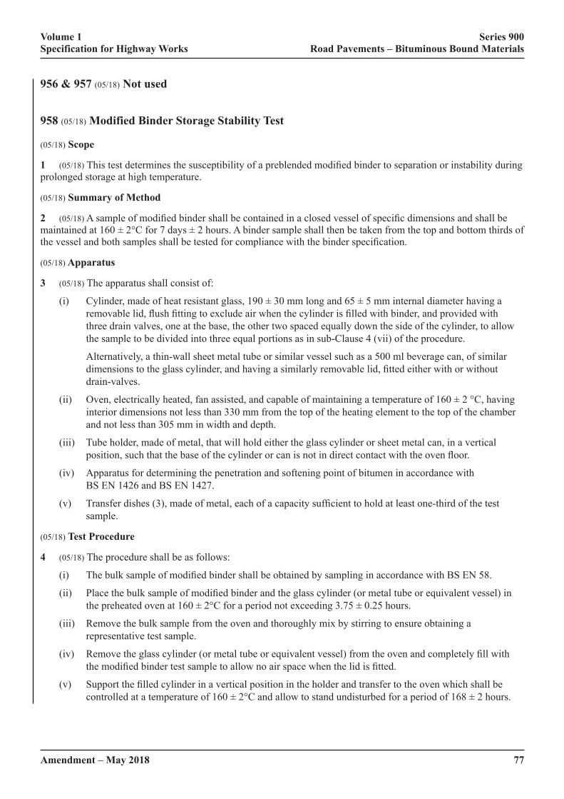
Volume 1 Series 900 Specification for Highway Works Road Pavements – Bituminous Bound Materials
Amendment – May 2018 77
956 & 957 (05/18) Not used
958 (05/18) Modified Binder Storage Stability Test
(05/18) Scope
1 (05/18)�This�test�determines�the�susceptibility�of�a�preblended�modified�binder�to�separation�or�instability�during�prolonged storage at high temperature.
(05/18) Summary of Method
2 (05/18)�A�sample�of�modified�binder�shall�be�contained�in�a�closed�vessel�of�specific�dimensions�and�shall�be�maintained�at�160�±�2°C�for�7�days�±�2�hours.�A�binder�sample�shall�then�be�taken�from�the�top�and�bottom�thirds�of�the�vessel�and�both�samples�shall�be�tested�for�compliance�with�the�binder�specification.
(05/18) Apparatus
3 (05/18) The apparatus shall consist of:
(i)� Cylinder,�made�of�heat�resistant�glass,�190�±�30�mm�long�and�65�±�5�mm�internal�diameter�having�a�removable�lid,�flush�fitting�to�exclude�air�when�the�cylinder�is�filled�with�binder,�and�provided�with�three drain valves, one at the base, the other two spaced equally down the side of the cylinder, to allow the sample to be divided into three equal portions as in sub-Clause 4 (vii) of the procedure.
Alternatively, a thin-wall sheet metal tube or similar vessel such as a 500 ml beverage can, of similar dimensions�to�the�glass�cylinder,�and�having�a�similarly�removable�lid,�fitted�either�with�or�without�drain-valves.
(ii)� Oven,�electrically�heated,�fan�assisted,�and�capable�of�maintaining�a�temperature�of�160�±�2�°C,�having�interior dimensions not less than 330 mm from the top of the heating element to the top of the chamber and not less than 305 mm in width and depth.
(iii) Tube holder, made of metal, that will hold either the glass cylinder or sheet metal can, in a vertical position,�such�that�the�base�of�the�cylinder�or�can�is�not�in�direct�contact�with�the�oven�floor.
(iv) Apparatus for determining the penetration and softening point of bitumen in accordance with BS EN 1426 and BS EN 1427.
(v)� Transfer�dishes�(3),�made�of�metal,�each�of�a�capacity�sufficient�to�hold�at�least�one-third�of�the�test�sample.
(05/18) Test Procedure
4 (05/18) The procedure shall be as follows:
(i)� The�bulk�sample�of�modified�binder�shall�be�obtained�by�sampling�in�accordance�with�BS�EN�58.
(ii)� Place�the�bulk�sample�of�modified�binder�and�the�glass�cylinder�(or�metal�tube�or�equivalent�vessel)�in�the�preheated�oven�at�160�±�2°C�for�a�period�not�exceeding�3.75�±�0.25�hours.
(iii) Remove the bulk sample from the oven and thoroughly mix by stirring to ensure obtaining a representative test sample.
(iv)� Remove�the�glass�cylinder�(or�metal�tube�or�equivalent�vessel)�from�the�oven�and�completely�fill�with�the�modified�binder�test�sample�to�allow�no�air�space�when�the�lid�is�fitted.
(v)� Support�the�filled�cylinder�in�a�vertical�position�in�the�holder�and�transfer�to�the�oven�which�shall�be�controlled�at�a�temperature�of�160�±�2°C�and�allow�to�stand�undisturbed�for�a�period�of�168�±�2�hours.
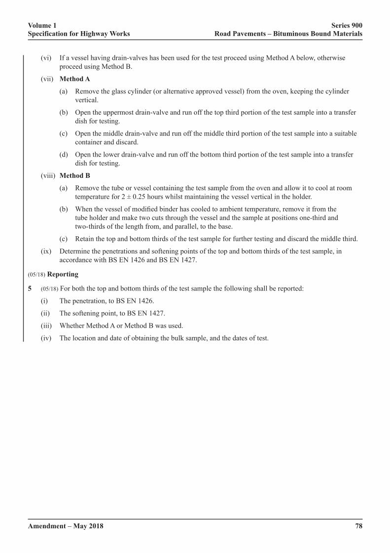
Volume 1 Series 900 Specification for Highway Works Road Pavements – Bituminous Bound Materials
78Amendment – May 2018
(vi) If a vessel having drain-valves has been used for the test proceed using Method A below, otherwise proceed using Method B.
(vii) Method A
(a) Remove the glass cylinder (or alternative approved vessel) from the oven, keeping the cylinder vertical.
(b) Open the uppermost drain-valve and run off the top third portion of the test sample into a transfer dish for testing.
(c) Open the middle drain-valve and run off the middle third portion of the test sample into a suitable container and discard.
(d) Open the lower drain-valve and run off the bottom third portion of the test sample into a transfer dish for testing.
(viii) Method B
(a) Remove the tube or vessel containing the test sample from the oven and allow it to cool at room temperature�for�2�±�0.25�hours�whilst�maintaining�the�vessel�vertical�in�the�holder.
(b)� �When�the�vessel�of�modified�binder�has�cooled�to�ambient�temperature,�remove�it�from�the�tube holder and make two cuts through the vessel and the sample at positions one-third and two- thirds of the length from, and parallel, to the base.
(c) Retain the top and bottom thirds of the test sample for further testing and discard the middle third.
(ix) Determine the penetrations and softening points of the top and bottom thirds of the test sample, in accordance with BS EN 1426 and BS EN 1427.
(05/18) Reporting
5 (05/18) For both the top and bottom thirds of the test sample the following shall be reported:
(i) The penetration, to BS EN 1426.
(ii) The softening point, to BS EN 1427.
(iii) Whether Method A or Method B was used.
(iv) The location and date of obtaining the bulk sample, and the dates of test.
Volume 1 Series 900 Specification for Highway Works Road Pavements – Bituminous Bound Materials
Amendment – May 2018 79F
NATIONAL ALTERATIONS OF THE OVERSEEING ORGANISATIONS
911TS/WG (05/18) Hot Rolled Asphalt Surface Course (Design Mixtures)
1 (05/18) Hot Rolled Asphalt surface course design mixes shall conform to BS EN 13108-4, the example in BSI PD�6691�Annex�C�and�requirements�specified�in�contract�specific�Appendix�7/1.�The�mixture�designation�shall�be one of the following:
(i) HRA 0/2 F surf xx/yy des
(ii) HRA 30/14 F surf xx/yy des
(iii) HRA 35/14 F surf xx/yy des
(iv) HRA 55/10 F surf xx/yy des
(v) HRA 55/14 F surf xx/yy des
(vi) HRA 0/2 C surf xx/yy des
(vii) HRA 30/14 C surf xx/yy des
(viii) HRA 35/14 C surf xx/yy des
(ix) HRA 55/10 C surf xx/yy des
(x) HRA 55/14 C surf xx/yy des
Unless�otherwise�specified�in�contract�specific�Appendix�7/1,�the�grade�of�bitumen�required�(xx/yy)�shall�be�40/60.
(05/18) Coarse Aggregate
2 (05/18) The resistance to polishing of the coarse aggregate for chipped mixtures shall be category PSV44 as defined�in�BS�EN�13043:2002,�clause�4.2.3.�For�unchipped�mixtures,�the�coarse�aggregate�shall�have�a�minimum�declared�PSV�and�a�maximum�declared�AAV�as�specified�in�contract�specific�Appendix�7/1.
(05/18) Coated Chippings
3 (05/18)�When�required,�coated�chippings�shall�be�either�14/20�mm�or�8/14�mm�size�in�accordance�with�BSI PD 6682-2,�as�specified�in�contract�specific�Appendix�7/1.�Coated�chippings�shall�also�comply�with�Clause 915.
(05/18) Marshall Stability and Flow
4 (05/18)�When�required,�the�Marshall�stability�and�flow�of�the�mixture�at�the�target�binder�content�shall�be�as�specified�in�contract�specific�Appendix�7/1.�Stability�and�flow�values�shall�be�determined�in�accordance�with�the�procedures in BS 594987, Annex H.
942TS (05/18) Stone Mastic Asphalt Surface Course (TS2010)
1 (05/18)�SMA�TS2010�specification�shall�be�as�per�Chapter�2�of�TS2010�Surface�Course�Specification�&�Guidance Issue 03 (October 2015) or subsequent issue, available via the following link:
http://www.transport.gov.scot/system/files/uploaded_content/documents/tsc_basic_pages/Transport/TSIA%2035-15%20%2B%20TS2010%20Ver03%20%28Oct%202015%29.pdf