series 6000 radio direction finding system user manual - doppler home
TRANSCRIPT

SERIES 6000
RADIO DIRECTION FINDING SYSTEM USER MANUAL
DDF6001F Display Processor
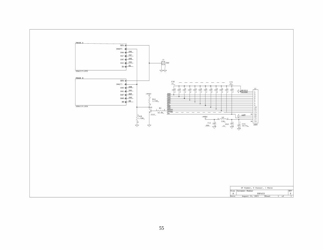
DDF609xE Fixed Site Antenna DDF5980B/5981B RF Summer
DDF5947/5948/5961/5962 Mobile Antennas DDF6079 Antenna Switch DDF6077 Serial Expander
DOPPLER SYSTEMS INC. PO Box 2780
37202 N. Bloody Basin Rd. Carefree, Arizona 85377
Tel: (480) 488-9755 Fax: (480) 488-1295
Copyright© 1995-2006, Doppler Systems Inc. All rights reserved. Issue 2006/12.
DOPPLER SYSTEMSDDF 6001

ii

iii
Warranty Information Doppler Systems Inc. will repair or replace, at their option, any parts found to be defective in either materials or workmanship for a period of one year from the date of shipping. Defective parts must be returned for replacement. In the US, contact the factory, or overseas your local distributor, for advice about returning any defective parts or equipment. If a defective part or design error causes your radio direction finder to operate improperly during the one-year warranty period, Doppler Systems Inc. will service it free of charge if returned at owner’s expense. If improper operation is due to an error on the part of the purchaser, there will be a repair charge. Doppler Systems Inc. are not responsible for damage caused by the use of improper tools or solder, failure to follow the printed instructions, misuse or abuse, unauthorized modifications, misapplication of the unit, theft, fire or accidents. This warranty applies only to the equipment sold by Doppler Systems Inc. and does not cover incidental or consequential damages. Doppler Systems radio direction finding equipment is designed to for locating interfering radio signals. It is not intended for use as a navigation aid, and in particular it is not to be used for aircraft or marine navigation.
Accessories Included
(1) User manual (1) 12 VDC, 1.5 amps, 110 VAC wall mount power supply (North American models) (1) DC power cable DDF6110 (automobile cigarette lighter plug to 2.5mm plug) (1) RS232 extension cable (2) 3.5 mm phone plugs #750 (1) Software manual (1) Set of software (CD)
Additional cables are available for various receivers including the ICOM R8500 and AOR AR5000 and AR8600.

iv
Table of Contents Warranty Information .................................................................................................................... iii Accessories Included ..................................................................................................................... iii Table of Contents........................................................................................................................... iv 1.0 Introduction............................................................................................................................... 1 2.0 Specifications............................................................................................................................ 2 3.0 Controls and Connectors........................................................................................................... 3 4.0 Installation ................................................................................................................................ 7
4.1 Fixed site selection................................................................................................................ 7 4.2 Fixed site installation ............................................................................................................ 7 4.3 Mobile installation ................................................................................................................ 7 4.4 Phone jacks ........................................................................................................................... 9 4.5 ICOM R7000 Receiver ....................................................................................................... 10 4.5 ICOM R7100 and R8500 Receivers ................................................................................... 10
5.0 Operation ................................................................................................................................ 16 5.1 Turn-on initialization .......................................................................................................... 16 5.2 Calibration .......................................................................................................................... 16 5.3 Direction Finding in the Continuous Mode (Version 4.19+) ............................................. 17 5.4 Direction Finding in the Pulse Mode (Version 4.19+) ....................................................... 18 5.5 Homing ............................................................................................................................... 19 5.6 Recommended Settings....................................................................................................... 19
6.0 Remote Control....................................................................................................................... 20 6.1 Introduction......................................................................................................................... 20 6.2 Hardware Interfaces ............................................................................................................ 20
6.2.1 Connector J1 (port #0) ................................................................................................. 20 6.2.2 Connector J2 (port #2) ................................................................................................. 20 6.2.3 Connector J4 (port #1) ................................................................................................. 21
6.3 Message Protocol ................................................................................................................ 21 6.3.1 ASCII Protocol ............................................................................................................ 21 6.3.2 CIV Protocol ................................................................................................................ 21
6.4 DDF6001 Messages ............................................................................................................ 21 6.4.1 ASCII Protocol ............................................................................................................ 21 6.4.2 CIV Protocol ................................................................................................................ 24
6.5 Non DDF6001 messages..................................................................................................... 26 6.5.1 ASCII Protocol ............................................................................................................ 26 6.5.2 CIV Protocol ................................................................................................................ 26
6.6 Typical Operation ............................................................................................................... 26 6.6.2 PC connected to port #0 (J1), RS232 receiver connected to port #2 (J2)........................ 26
6.6.6 Multiple DDF6001s and Receivers Connected to PC Using Radio Modems ............. 28 6.6.7 Two DDF6001s and Receivers Connected to PC Using an Ethernet or Internet Connection ............................................................................................................................ 28 6.6.8 Other Networking Options........................................................................................... 29

v
6.6.9 Command Interlock ..................................................................................................... 29 7.0 Test Software .......................................................................................................................... 41 8.0 Servicing ................................................................................................................................. 42
8.1 Schematics .......................................................................................................................... 42 8.2 EPROM replacement .......................................................................................................... 42

1
1.0 Introduction The Series 6000 is a high performance radio direction finding system that operates using the synthetic Doppler principle in which a circular array of antennas are combined in a way that simulates a single element rotating in a circular path. As the simulated element approaches the wave front of an RF signal, the frequency increases due to the Doppler effect, and as it recedes from the transmitted source, the frequency decreases. The amount of frequency change (deviation) is related to the speed of rotation and the diameter of the antenna array, while the modulation frequency is equal to the frequency of rotation (the antenna sweep frequency). When connected to a narrow band communication receiver, the sweep frequency is present on the audio output. To obtain the bearing angle, the direction finder processes this audio output. Many features are present in the Series 6000:
• The system may be used with either an 8-element high accuracy fixed site antenna or a 4-
element magnetic mount antenna for mobile operation.
• The sweep frequency may be set to 300, 600, 1200 or 2400 Hz to avoid tone frequencies that may be present in the signal modulation.
• Advanced signal processing is used to detect the signal with the receiver either squelched
or unsquelched. Signals as short as 80 msec can be detected using the lastest firmware version (V4.19 or later).
• The sweep direction automatically reverses from clockwise to counterclockwise to
compensate for asymmetries in the receiver.
• An internal audio amplifier and loudspeaker are provided for monitoring the signal, and a sharp notch filter removes the sweep frequency for clarity.
• Two serial ports permit remote control of both the direction finder and an associated
receiver from a single PC COM port. The secondary serial port may be configured for either RS232 (ASCII) operation or as a CIV bus.
• The display is housed in an attractive metal enclosure to enhance electromagnetic
compatibility (EMC). The fixed site antennas are constructed of corrosion resistant materials and are designed for wind speeds up to 45 m/s (100 mph).
The latest processor in the Series 6000 is the DDF6001. This unit is network compatible with earlier model DDF6000 processors, but it provides a different drive to the antenna electronics. For this reason, the DDF6001 must be used with the new antennas DDF609x while the DDF6000 is used with the antennas DDF605x. To prevent inadvertent mixing of these processors and antennas, the sex of the antenna connectors is different on these two models.

2
2.0 Specifications Performance specifications apply to a DDF6001 when connected to a fixed site antenna (DDF6092, DDF6095 or DDF6097) and a narrow band fm receiver such as the Icom R7000, R7100 or R8500.
Frequency range (Depends on 125-250 MHZ (DDF6092-xx) (antenna; -xx indicates cable length 250-500 MHZ (DDF6095-xx) in feet. Elements are nominally tuned 500-1000 MHZ (DDF6097-xx) for 150, 450 or 860 MHz). Bandwidth (From nominal tuned 20% (+/-10%) minimum frequency for 3 dB sensitivity degradation). Bearing display 16-LED circle and 3-digit LED display
Bearing display rate 2 Hz
Bearing accuracy (1 sigma) 2 degrees
DF sensitivity (typical) -130 dBm, continuous signal
Bearing averaging (selectable) 1, 2, 4, 10 or 20 samples
Antenna sweep rate 300, 600, 1200 or 2400 Hz
RF attenuator (selectable) 0 or 25 dB
Audio input range 0.01 to 0.6 VRMS
Audio output 0.5 watts maximum
S-meter input range -10 to +10 VDC
Serial interfaces (2) RS232 ports
(1) CIV port
Power requirement 11 to 14 VDC
Current consumption 1.0 amp
Operating temperature (display) 0 to 50 degrees C
Dimensions (display - H x W x D) 108 x 171 x 235 mm (4.25 x 6.75 x 9.25 in)
Weight (display) 1.9 Kg (4.1 lbs)

3
3.0 Controls and Connectors Figure 3-1 on shows the front panel controls and figure 3-2 shows the rear panel connectors. The items marked in the following paragraphs refer to the controls and connectors in these figures.
1 Press the red power switch to turn the unit on or off.
2 Press this switch to dim the front panel LEDS. Pressing it again returns the LEDS to full brightness.
3 Bearing data is computed twice per second. The front panel displays a moving average of the last N bearings calculated. The number of bearings averaged, N, may be increased or decreased by pressing the up or down arrow keys. Note that selecting N = 1 causes CW and CCW rotation bearings to be displayed, while higher settings average both CW and CCW rotations (recommended).
4 Bearing is displayed by illumination of one of the red LEDS on the circular display. The center yellow LED indicates that power is on.
5 Bearing angles in degrees are displayed in the 7-segment display. Both the circular LED display and the digital display are held for 10 seconds after the signal disappears. To help distinguish when the bearing is updating and when it is being held, the decimal point following the units’ digit alternates on to off whenever the bearing updates.
6 Signal strength is indicated in this 7-segment display. It should be calibrated so that the signal strength is 0 when no signal is present and 9 when a very strong signal is present. See the description of controls 8, 10 and 11 for the method of calibrating the S-meter. The S-meter displays a dash if the S-meter input is not connected or if the display has not been calibrated.
7 Antenna rate of rotation can be increased or decreased by pressing the up or down arrows here. When a sweep rate of 0 is selected, all antennas are turned ON. This mode is useful in detecting a very weak signal, but bearings are not displayed.
8 Switch enables or disables the calibration mode. The calibration mode must be enabled for the bearing and S-meter calibration switches to be effective.
9 Pressing this switch when the calibration mode (see 8 above) is enabled causes the present bearing to be set to 0 degrees. Momentarily pressing this switch when the calibration mode is not enabled causes the present bearing to be incremented by 1 degree. If the switch is held down, the bearing changes in steps of 10 degrees.
10 Switch calibrates the S-meter to 9 on the present signal, provided the calibration mode is enabled (see 8 above).

4
11 Switch calibrates the S-meter to 0 on the present signal, provided the calibration mode is
enabled (see 8 above).
12 Press this switch to change the direction finder alternately from the Continuous to the Pulse mode and back. The DF should be used in the Continuous mode on most signals (voice, unmodulated carriers, etc.) and in the Pulse mode when an external Gate signal is present.
13 Switch causes a 25 dB attenuation of the RF input to the commutation electronics.
14 J1 is an RS232 serial interface configured as a DCE. May be connected directly to PC using a 9-pin male to 9-pin female straight through cable. See section 6.2.1, for details of this interface.
15 J2 is an RS232 serial interface configured as a DTE. May be connected to a receiver having an RS232 input or to an optional DDF5921 remote display unit. See section 6.2.2, for details of this interface.
16 J3 is the receiver audio input. Connect to the external speaker output of your receiver using the supplied 3.5 mm plug.
17 J4, CIV interface. May be connected to the CIV remote control interface on your ICOM receiver. See section 6.2.3, for details of this interface.
18 J5 is the S-meter input. Connect to the receiver’s S-meter output using the supplied 3.5 mm plug.
19 J6 is the external speaker output. May be connected to an external speaker (not supplied) using a 3.5 mm plug.
20 J7 is the DC power input. Connect to +12 VDC using the supplied 2.5mm to cigar plug cable, or on North American models from the supplied 110 VAC power supply.
21 J8 is the antenna control cable output. Connect to the 15-pin cable supplied with the 609x series fixed site antennas or the RF summer used for mobile operation.
22 J9 is the antenna switch output. Used with the DDF6079 three-antenna switch to select VHF, UHF1 or UHF2 antennas.
23 J10 is the auxiliary input. A TTL level Gate signal is applied at this connector in the Gated Pulse mode.

5
Figure 3-1 Front Panel Controls
DOPPLER SYSTEMSDDF 6001

6
Figure 3-2 Rear Panel Connectors

7
4.0 Installation
4.1 Fixed site selection For maximum range, you will want to select a fixed site location that has a high elevation and a clear line of sight to the area you intend to direction find in. Unfortunately, broadcast and other transmitters already occupy many such sites, and these must be avoided, as the direction finder is very broad banded. Before expending any great effort installing the direction finder at any fixed site, try it out first. The input preamplifiers used in the summing electronics can be damaged if exposed to more that a few hundred mill watts of RF power. Normally, this is not a problem, but you should not locate the DF antenna very close to a transmitter (especially one in the same frequency band as the DF antenna). If you plan to link the DF to another location using a data radio, you should select a data radio in a frequency band different from that of the direction finder. Position the data radio antenna for minimum coupling to the direction finder antenna.
4.2 Fixed site installation Series 6000 fixed site direction finder antennas are designed for mast mounting. Your DF antenna should be mounted on the top of the mast, and should be clear of other metal objects, antennas, etc. A side arm mount on a tower would be a very poor choice for mounting the antenna. Figure 4-1 shows a typical installation. Antenna assembly is different depending on whether a single antenna has been ordered or a two or three antenna stack is used. Follow the directions supplied with the antenna for assembly. After installing the antenna, secure the control and RF cables to the mast using nylon ties so that they are kept away from the antenna elements. The audio output from the receiver should be connected to the DF audio input (J3). The receiver’s S-meter output can be connected to J5. These cables can be made using the supplied Switchcraft 3.5 mm plugs or prebuilt cables may be ordered from the factory. DC power is connected through J7 from a 12 VDC/1.5A power supply. Figure 4-2 shows the fixed site system cabling.
4.3 Mobile installation Four antenna elements are used for mobile operation. At frequencies below 500 MHZ, magnetically mounted quarter wave whips are used. These antennas must provide a good coupling to the ground

8
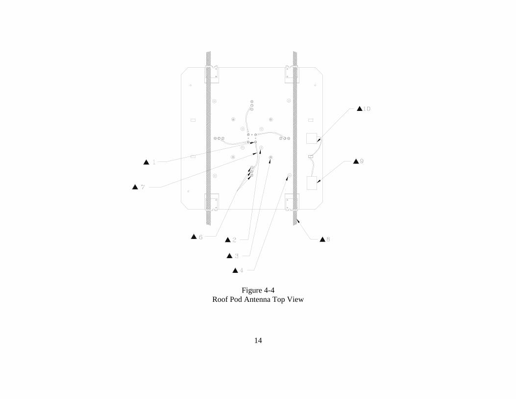
plane, and must be of exactly the same type. It is especially important that the coaxes used have the same length. Doppler Systems antennas DDF6061 and 6062 use the same magnetic mount base and cover the frequency ranges 88-136 and 136-500 respectively. Cut the whips to resonance using the chart provided with the antennas and space them between 1/8 and 1/4 wavelength apart on the car roof. To avoid damage to the input circuitry used in the RF summer, touch the antenna ground plane before attaching the whips to the magnetic mounts. It is important that the vehicle provides at least 1/4 wavelength of ground plane outboard of the antennas. It is a good idea to remove any other antenna from the car when using the direction finder to avoid its affecting the response pattern of the antenna. If you need to use another antenna, try experimenting with its location to minimize the coupling with the DF antenna. Do not transmit more than a few watts in the immediate vicinity of the DF antenna - especially if the transmit frequency is in the same frequency range as that of the DF antenna. It is possible to damage the RF summer if more that a few hundred milliwatts of RF power are induced into its input. Place the RF summer (DDF5980) on the car with the cables oriented towards the rear of the car. Connect the magnetic mount antenna cables to the corresponding TNC connectors on the RF summer. (That is, the left front antenna to the left front connector, etc.) Locate the summer near the back of the car (the lid of the trunk or boot) so that the magnetic mount antenna cables do not have excessive slack. Secure the four antenna cables together with nylon ties so that they are not free to move around and touch the antenna elements. Route the control and RF cables through an open window to the direction finder and receiver. For mobile operation in the 700-1000 MHZ band, antenna DDF5947 should be mounted directly on top of the RF summer. This antenna provides an extended ground plane, a wind shroud, and four stub type antennas built into TNC connectors. Place the assembled RF summer/antenna in the center of the car roof. Connect the receiver audio output to the DF audio input (J3) and connect the RSSI signal from the receiver to J5 on the direction finder. These cables can be built using the supplied Switchcraft 3.5 mm plugs or you can order prebuilt cables from the factory. The DF power is supplied to J7 from the cigar lighter using cable DDF6110. If you want to power the receiver from the same outlet, use a “Y” adapter. Wiring of the mobile DF is shown in Figure 4-3. The roof pod antenna provides a convenient platform for mounting all of the antennas and the RF summer. Referring to Figure 4-4, assemble the roof pod as follows: Mount the RF summer DDF5981 11 below the ground plane in the center of the platform using the four 6-32x5/16 screws provided with the summer. Connect the coax cable and control cable supplied with the RF summer and route these out through one of the rectangular holes on one of the rear support brackets.

9
From the following table, locate the antenna elements and mounting locations for the frequency you will be using and mount the antennas. Frequency (MHZ)
Antenna Elements 13
Antenna Mounts
125-175 (NBFM)
445 mm (17.5 inch) whips
175-250 (NBFM)
5/16-24 stud mounts on 305 mm (12 inch) square 3
250-350 (NBFM)
350-500 (NBFM)
152 mm (6 inch) whips
5/16-24 stud mounts on 152 mm (6 inch) square 2
500-700 (NBFM)
700-1000 (NBFM)
73 mm (2.875 inch) stubs
TNC mounts on 76 mm (3 inch) square 1
Connect the coax jumper cables with the right angle TNC connectors 7. If you are using the antenna in the 700-1000 MHZ range, these cables are not used; otherwise connect one end of each cable to a TNC connector on the RF summer. Connect the other end to the TNC connector that corresponds to the 6 or the 12 inch antenna mounting square. (See Figure 4-4). Set the ground plane on the car roof with the RF summer cables at the rear of the car. Run the cable straps 11 through the door frames (or windows) and fasten them securely inside the car. See Figure 4-5. Set the cover 14 down over the ground plane and fasten it with the four latches
12. Be sure that the cover is firmly attached to the car before driving. Route the cables from the RF summer through a rear window.
4.4 Phone jacks The phone jacks used on the DDF6001 are Switchcraft “Tini-Jax” connectors. These are commonly referred to as 3.5 mm connectors, but they actually measure 3.58 mm (0.141 inch) diameter. Other 3.5 mm connectors such as are used on ICOM receivers measure closer to 3.50 mm (0.138 inch) diameter. For reliable operation, mating plugs must be Switchcraft Type 750, which are supplied with the DDF6001. These plugs normally mate with the 3.5 mm jacks used on the ICOM receivers, but the ICOM 3.5 mm plugs do not reliably mate with the Switchcraft Tini-Jax connectors used in the DDF6001. Occasionally, a 3.5 mm jack may be encountered that will not accept the Switchcraft 750 plug. If this occurs, you can either replace the Switchcraft plug with a 3.5 mm plug, or modify the Switchcraft plug by lightly sanding the tip to reduce its outside diameter.

10
4.5 ICOM R7000 Receiver The ICOM R7000 can easily be modified to provide an S-meter output for the DDF6001. Remove the top cover and locate the Main Unit PWB on the left side of the receiver and the spare RCA phono jack (J7) on the rear panel. Solder a 5.1 K resistor to the center pin of J7 and solder an insulated wire to the other end of the resistor. Route the wire to the topside of the Main Unit and carefully solder the other end of the wire to pin 1 of IC4. IC4 is an 8-pin DIP op amplifier type NMJ4558D. (Solder the wire directly to the IC lead using a minimum amount of heat and a very small tip iron).
4.5 ICOM R7100 and R8500 Receivers On the ICOM R7100 or R8500 you can connect the S-meter input directly to the AGC output jack. Note that the AGC jack on the R8500 receiver is used for two functions. Normally, it provides an AGC output that is compatible with the DDF6001; however, it can also be used for a discriminator output by changing a jumper inside the receiver. Refer to the R8500 manual if it appears that the receiver jack is not providing an AGC output. The default CIV address for the R8500 is 4A (hex). This is 74 (decimal). Some of the software programs require a decimal entry while others require a hex entry. The R8500 allows baud rates of 300, 1200, 4800, 9600 or 19200. Do not attempt to connect the R8500 to the direction finder at 2400 baud on port 1 (the CIV jack). The R8500 can be programmed for “transceive” operation in which any change of its frequency (for example, turning the front panel tuning knob) causes the new frequency to be broadcast on the CIV port. Be sure that the CIV TRANS is turned OFF. Refer to the R8500 instruction manual for these settings.

11
Figure 4-1 Typical Fixed Site Antenna

12
Fixed Site Antenna
Size Document Number Rev
Date: Sheet of
FIGURE 4-2
Fixed Site Installation
A
1 1Tuesday , December 26, 2006
Coax CableDDF6116-xx
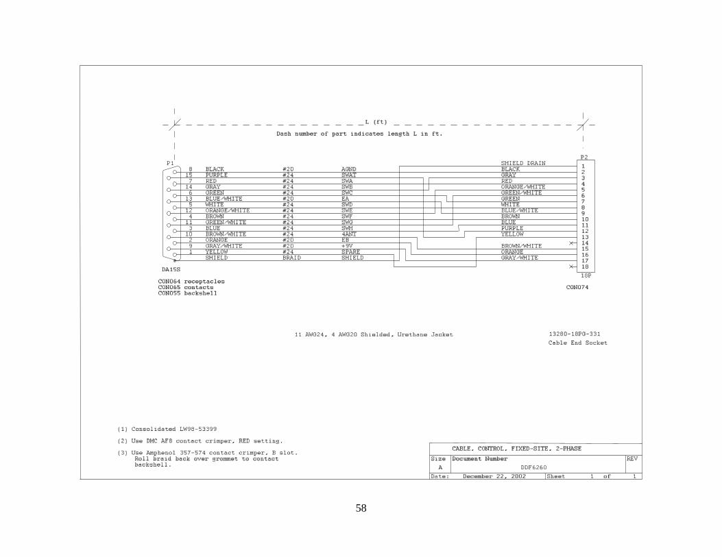
Control CableDDF6260-xx
RECEIVER
Ext SpkrANT
SupplyPower
+12VDCAGC (RSSI)
DDF6001
DDF6092, 6095, or 6097
Audio
RSSI
P3
3.5mm
P5
3.5mm
A B C D E F G H
P1TNC
BNC
8157
146
135
124
113
10291
P8
DA15S
P72.5mm
P2
18P Circular

13
Coax CableDDF6116-12
Control Cable
Size Document Number Rev
Date: Sheet of
FIGURE 4-3
Mobile Installation
A
1 1Tuesday , December 26, 2006
JC
TNC
RECEIVER
Ext SpkrANT
DDF6001
DDF5980 RF SUMMER
JD
TNC
Mobile Antenna
RSSI
DDF6247-12
AGC (RSSI)
AUDIO
DDF6110 Cable
or 5947DDF6061, 6062,
A B C D
P3
3.5mm
P5
3.5mm
Auto power plug
P1TNC
BNC
8157
146
135
124
113
10291
P8
DA15S
P7
2.5mm
P2 9P Circular
JA
TNC
JB
TNC
14
Figure 4-4
Roof Pod Antenna Top View

15
Figure 4-5 Roof Pod Antenna Side View

16
5.0 Operation
5.1 Turn-on initialization During the initial turn-on of the DDF6001, the parameter values that were last set (sweep rate, port 2 communications parameters, etc.) are restored. There are two exceptions:
(1) The software determines whether a 4 or an 8-element antenna is installed and selects the corresponding waveforms.
(2) The software determines whether a plug has been inserted in the CIV jack (J4) and selects the appropriate protocol (either CIV or ASCII). During the initial turn-on, the bearing and S-meter displays will momentarily indicate the software version used by the processor and the DF serial address. The later is especially important because it can be changed (under serial command) and if the address is forgotten, no CIV communication is possible. The software version is displayed as X.XX in the bearing window and 1 in the S-meter window. The DF address will be displayed as XXX (the decimal address value) in the bearing window and 2 in the S-meter window. It is also possible to restore the factory default values of all parameters by entering from the front panel controls: Sweep rate = 0, CAL enabled, BRG = 0. The default parameters are listed in Table 6-1. Note, however, that the bearing calibration values will also be returned to the factory default values and a recalibration will probably be necessary.
5.2 Calibration The bearing angle and the S-meter display are easily calibrated from the front panel. If you are using the direction finder in a car or boat, calibrate the bearing display so it reads 0 degrees when receiving a signal from straight ahead. To perform this calibration, use a strong steady signal such as a repeater output, NOAA weather station, etc. Be sure the vehicle is in an area free of reflections with a clear line of sight to the known transmitter. Select the CAL mode by pressing the CAL switch. The CAL light will remain ON. Then press the BRG = 0 switch, and the bearing should read 0 degrees. Repeat this procedure for sweep rates of 300, 600, 1200 and 2400 Hz. Do not try to calibrate the bearing to 0 with the sweep rate set for 0; this is a special command that is used to restore the factory default parameter settings (see above). If you are using the direction finder at a fixed location, use the following alternate procedure to calibrate the bearing. Tune in a known transmission and determine the bearing from the direction finder site using a map. Increment the bearing angle by pressing the BRG = 0 switch without first enabling the CAL switch. Each time the switch is pressed, the bearing will increment 1 degree, but

17
if the switch is held in, the bearing will increment in steps of 10 degrees. Hold the switch down until the bearing is close to the desired value, and then pulse it in the remaining steps. The direction of rotation reverses every 0.5-second. This feature allows nonlinearities in the receiver to be compensated by averaging consecutive bearing readings. If the number of averages is selected to be 1 the individual bearing data will be displayed, and if the system needs calibration, the readings will alternate between two different values. Be sure to recalibrate the unit if you see this occurring. Normally, you should operate the direction finder with 2 or more averages selected in order to obtain the benefits of the clockwise/counterclockwise rotation. If the S-meter is not connected to the receiver, or if it has not been calibrated, the S-meter will display a dash. To calibrate the S-meter, the CAL switch must first be enabled, then the SIG=9 switch pressed when a strong signal is present, and the SIG=0 switch when no signal is present.
5.3 Direction Finding in the Continuous Mode (Version 4.19+) The simulated rotation of the antenna by the direction finder produces a tone in the receiver’s audio output, which you will not normally hear because it is filtered out in the direction finder before it is passed to its speaker; you can hear it if you wish by removing the audio plug from the receiver’s external speaker output. The DF measures the magnitude and the phase of the tone every 10 milliseconds and calculates bearing angle from this data every second. The DF software determines whether a signal is present by examining the statistics of the sampled data. If the phase stability of the tone is less than some (setable) threshold, then it is concluded that a signal is present and the bearing is displayed. This scheme makes the system independent of the receiver’s volume control setting, so the volume may be set at any comfortable level. In addition, the receiver’s squelch can be set normally or it can be opened so that the receiver is unsquelched. If no signal is present, the DF will detect this condition from the lack of a stable sweep tone, and will not update the display. The bearing stability test is performed every 80 msec, so signals having a duration as short as 80 milliseconds can be detected and displayed. The sweep rate can be adjusted set to 300, 600, 1200 or 2400 Hz from the front panel. Maximum sensitivity and stability is obtained at the higher sweep rates, but there may be occasions when a lower sweep rate is desired. For example, if the signal itself contains a 1200 Hz tone, you would want to use a sweep rate other than 1200 Hz. A sweep rate of 2400 Hz results in a peak deviation that exceeds the 15 KHz bandwidth of most narrow band fm receivers. You will notice distortion of the transmitted audio with this sweep rate when receiving with a narrow band fm receiver. This sweep rate is useful however if you need to DF a wide band fm signal for which you must, of course, use a wide-band (150 KHz bandwidth) receiver.

18
The front panel display updates twice every second. Bearings are retained for 10 seconds, and then the display is blanked. To distinguish an updated bearing from a retained bearing of the same value, the decimal point on the display alternates ON and OFF whenever the display is updated. If the number of averages is set to 1, then the bearing display is that calculated by the software during the preceding 0.5-second interval. The processor can also calculate a moving average of the preceding bearings. This will cause the bearing angle to be more stable, but it will also be less responsive to actual changes in the bearing. As discussed in Section 5.2, the antenna sweep direction is reversed every 0.5 seconds to permit reduction of errors due to non-linearities in the receiver. While the direction finder can be used with the number of averages set to 1, it is usually best to set it to 2 or higher to obtain the benefits of averaging opposite direction sweeps. The RF summer used in the direction finder antenna has a gain between 9 and 10 dB and a noise figure between 3 and 4 dB in the VHF band. The preamplifiers used are broad band devices which can generate intermod products if very strong input signals are present. Depending on the location of the antenna and the frequency being used, you may notice an increase in the noise level of the receiver which is due to mixing of two strong input signals (for example, a broadcast fm station and a television video or audio signal). If this appears to be happening, first apply 10 or 20 dB attenuation at the receiver’s input. (Many receivers have a switchable input attenuator for this purpose). If this does not help, try enabling the attenuator switch on the direction finder which causes the preamplifiers to be bypassed.
5.4 Direction Finding in the Pulse Mode (Version 4.19+) A gated pulse mode is enabled by pressing the Pulse Mode switch. In this mode, a external gate signal is used to tell the direction finder that a signal is present. This signal is a TTL signal which is applied through the AUX input jack on the rear panel. The gate signal must be greater than 10 msec and shorter than 500 msec. The bearing is calculated at the end of the gate signal. This method permits the receiver volume to be adjusted without affecting the bearing, and the receiver squelch can be set normally or left open. Maximum sensitivity is obtained with the receiver unsquelched. DF sensitivity in this mode is better than in the Continuous mode, but of course the key is how sensitive the external processor is in determining the Gate signal. Antenna rotation can be controlled using external serial commands 941 and 942. Consecutive bearings may be averaged. The number of samples averaged may be selected to be 1, 2, 4, 10 or 20. This mode should not normally be used since the Continuous mode provides short pulse detection capability and does not require an external Gate pulse.

19
5.5 Homing When the direction finder is used to home on a signal source, the following guidelines should be followed.
Take an assistant with you. Don’t try to read the display and drive at the same time.
Try to keep out of high multipath areas (buildings, etc.) as long as possible.
Avoid strong interfering signal locations (broadcast stations, etc.)
Keep moving when the signal is present. Multipath averages out spatially (not temporally).
5.6 Recommended Settings For either fixed site or mobile settings, we recommend starting with Averages = 2, Sweep Rate = 1200 and a receiver bandwidth between 10 and 15 KHz. If using the R8500 receiver, be sure that the CIV transceive mode is set to OFF.

20
6.0 Remote Control
6.1 Introduction Serial communication ports are provided at two of the rear panel connectors chosen from the three available. Port #0 is connected at J1; port #1 is connected to J4 and port #2 to J2. On power turn-on, the DDF6001 determines whether a plug has been inserted into the 3.5 mm jack J4, and if it has, the system operates using CIV protocol at port #0 (J1) and port #1 (J4). The DE9P connector at J2 (port #2) used for the connecting an AOR receiver in this mode. If during power turn-on, a plug was not inserted into J4, then both port #0 (at J1) and port #2 (at J2) will operate using ASCII message protocol. Port #1 (J4) is not used in this case. CIV is a packet format 2-wire bus system developed by ICOM and used in most of their radios. Multiple CIV devices can be placed on the CIV bus to communicate with each other. Each device has a unique address.
6.2 Hardware Interfaces Figure 6-1 shows the wiring of serial interface connectors J1, J2 and J4. Note that the signal names are defined for the Data Terminal Equipment (DTE) device, so that TXD is an input and RXD an output on J2 that is wired as Data Control Equipment (DCE).
6.2.1 Connector J1 (port #0) Connector J1 is a DE9S wired as Data Control Equipment (DCE). All voltage levels and impedances are RS232. J1 may be connected to the serial port of a PC using a straight through DE9P to DE9S cable. CTS, RTS, DSR, DTR, CD and RD are not connected. The port #0 baud rate is 2400 with 8 data bits; no parity and 1 stop bits.
6.2.2 Connector J2 (port #2) Connector J2 is a DE9P wired as Data Terminal Equipment (DTE). Transmit and receive voltage levels and impedances are RS232. J2 may be connected to a PC using a null modem DE9S to DE9S cable. RTS, CTS, DSR, DTR, CD and RD are not connected. The default baud rate of port #2 is 1200 with 8 data bits, no parity and 1 stop bit. The baud rate may be changed to 2400, 4800 baud or 9600, parity may be changed to even or odd, the number of data bits can be changed to 7 and the stop bit length can be changed to 2 by serial commands. When the

21
DF is set to operate with an AOR receiver or the DDF5921 display, the baud rate of port #2 is set to 4800 baud. Do not change the baud rate if you are using either of these devices.
6.2.3 Connector J4 (port #1) Connector J4 is a 3.5 mm jack connected for CIV bus operation. Transmit and receive voltage levels are TTL. The output is pulled up to +5 VDC through a 5.1 K resistor. The default baud rate is 1200 with 8 data bits, no parity and 1 stop bit. The baud rate may be changed to 2400, 4800 baud or 9600, parity may be changed to even or odd, the number of data bits can be changed to 7 and the stop bit length can be changed to 2 by serial commands.
6.3 Message Protocol
6.3.1 ASCII Protocol ASCII messages may contain any string of standard (7 bit) ASCII characters (hex 00 through 7F). A <CR> (hex 0D) character terminates the string. 80 characters (including the <CR>) is the maximum length of the string. Line-feed characters (hex 0A) are ignored.
6.3.2 CIV Protocol CIV message format is:
PR PR RA TA CN SC DT SF where PR is the preamble (hex FE), RA is the receive address, TA is the transmitter address, CN is the command number, SC is the (optional) subcommand, DT is the data (and may be several characters in length), and SF is the message suffix (hex FD). 80 characters is the maximum length of a CIV message (including prefixes and suffix). Received messages are buffered, and if a jamming character (hex FC) is detected anywhere within the message, the message is ignored. Also, the received message must begin with at least two prefix characters or it will be ignored.
6.4 DDF6001 Messages
6.4.1 ASCII Protocol In ASCII mode, DDF6001 commands may be received through port #0 (J1) or port #2 (J2). The first character in the message must be a $ (hex 24) which is followed by a 1 to 3 character command, followed by the <CR> character. Valid DDF6001 commands are listed in Table 6-1.

22
Recognized DDF6001 commands (except for commands 0, 943, 982, 983 and 997) are executed and acknowledged by the message "$OK<CR>". Unrecognized DDF6001 commands (such as $409<CR>) are acknowledged with the message "$NG<CR>". The response to command 0 (DF data request) is the message "XXXYZ<CR>. In this message, XXX is the bearing angle, Y is the signal strength, and Z is a parameter indicating the validity of the returned data. All characters are ASCII digit characters (hex 31 means 1). In the DDF6001, bearing and signal strength are computed on a 0.5 second interval. The sampling interval of the serial readout (command 0) may be shorter or longer that 0.5 second, and the validity flag Z provides a method to synchronize the two clock cycles. After the data is read out serially, the validity flag is set to zero, so if a second readout is made before the bearing is updated, the validity flag Z is returned equal to 0. After the data is updated within the DDF6001, the validity flag is set to 1 if the data meets the signal to noise requirement, and it is set to 2 if it does not. It is recommended that the PC which is requesting the bearing data do so at a rate of approximately twice per second, and that it ignore any returned data that does not have a validity Z equal to 1. The response to command 943 (DF parameters) is RABCDE<CR> where R indicates a parameter message and ABCDE are characters (bytes) representing the settings of the direction finder as defined below. All characters are ASCII. Byte A. Serial Port Parameters (Port #1 and Port #2)
x s x p p d b b
7 6 5 4 3 2 1 0Bit Position
Stop Bits (s) Parity (p) Data Bits (d) Baud Rate (bb) 0 = 1 bit 1 = 2 bits
0 = none 1 = odd 2 = even 3 = mark
0 = 7 bits 1 = 8 bits
0 = 1200 baud 1 = 2400 baud 2 = 4800 baud 3 = 9600 baud
Byte B
x k x r r r r r
7 6 5 4 3 2 1 0Bit Position
k = 0 means front panel switches are disabled k = 1 means front panel switches are enabled For DF software versions less than 4.18, r/10, represents the signal to noise threshold for bearing detection (e.g. r = 3 means s/n ratio is set to 0.3).

23
For DF software versions 4.19 and greater, r/20, represents the bearing stability threshold (e.g. r = 6 means threshold is set to 0.3 radians). Byte C
x a x s t t t t
7 6 5 4 3 2 1 0Bit Position
a = 0 means auto output is off a = 1 means auto output is on s = 0 means DF is not in self test mode s = 1 means DF is in self test mode t*100 is the bearing update rate in ms (e.g. t = 5 means update rate is 500 ms). Byte D
x n x p p p p p
7 6 5 4 3 2 1 0Bit Position
n = 0 means 4 antenna elements are being used n = 1 means 8 antenna elements are being used p = pulse duration in ms (used in the pulse mode) Byte E
m m 0 a a x d d
7 6 5 4 3 2 1 0Bit Position
Port #2 Output (m) Antenna Switch (a) DF Mode 0 = Standard 1 = DDF 5921 display 2 = AOR Receiver
0 = UHF2 1 = UHF1 3 = VHF
0 = Continuous 1 = Pulse 2 = Special
The response to command 982 (identify hardware) is (for example) H6001f<CR>. All characters are ASCII. The response to command 983 (identify software) is (for example) S4.23<CR>. All characters are ASCII. The response to command 997 (send panel message) is PXYZ<CR> that is decoded as described below. All characters are ASCII.

24
Number of averages
X
1
0
2
1
4
2
10
3
20
4
Sweep rate
Y
0
0
300
1
600
2
1200
3
2400
4
Cal
Pulse
Atten
Dim
Z
Off
Off
Off
Dim
0
Off
Off
Off
Bright
1
Etc.
On
On
On
Dim
E
On
On
On
Bright
F
6.4.2 CIV Protocol DDF6001 commands may be received through port #0 (J1) or port #1 (J4). The transmit address in the message must be that of the controller (hex E0) and the recipient address must be the DDF6001 (default hex 01). Valid DDF6001 commands are listed in the Table beginning on page 24.

25
Recognized DDF6001 commands (except for commands 0, 943, 982, 983 and 997) are executed and acknowledged by the CIV OK message "FE FE E0 01 FB FD" (assuming the DF address has not been changed from the default value of hex 01). Unrecognized commands are acknowledged by the No Good message "FE FE E0 01 FA FD (again assuming the default DF address). The response to command 0 (DF data request) is the message "FE FE E0 01 U V FD". In the message, U and V contain the bearing, S-meter and validity data using a simple data compression scheme. To decompress the data, the PC must implement the following calculation:
validity = int (V/64) temp1 = int (V - 64*validity) temp2 = int (temp1/16)
temp3 = temp1 - 16*temp2 smeter = temp3 - 1; angle = temp2*200 + U
In the DDF6001, bearing and signal strength are computed on a 0.5 second interval. The sampling interval of the serial readout (command 0) may be shorter or longer that 0.5 second, and the validity flag Z provides a method to synchronize the two cycles. After the data is read out serially, the validity flag is set to zero, so if a second readout is made before the bearing is updated, the validity flag Z is returned equal to 0. After the data is updated within the DDF6001, the validity flag is set to 1 if the data meets the signal to noise requirement, and it is set to 2 if it does not. It is recommended that the PC which is requesting the bearing data do so at a rate of approximately twice per second, and that it ignore any returned data that does not have a validity Z equal to 1. The response to command 943 (DF Parameters) is FE FE E0 01 R A B C D E FD assuming that the DF address is 1. The characters R, X, Y, and Z are ASCII. A, B, C, D, and E are integers that are decoded as indicated in the tables given in the preceding section 6.4.1 to determine the direction finder settings. The response to command 982 (identify hardware) is FE FE E0 01 H 6 0 0 1 f FD assuming that the DF address is 01. The characters H, 6, 0 and f are ASCII (for example hex 36 = 6). The response to command 983 (identify software) is FE FE E0 01 S 4 . 2 3 FD assuming that the DF address is 01. The characters S, 3, ., 0, and 1 are ASCII (for example, hex 33 = 3). The response to command 997 (send panel message) is FE FE E0 01 P X Y Z FD assuming that the DF address is 01. The characters P, X, Y and Z are ASCII. X, Y and Z are integers that are decoded as indicated in the tables given in the preceding section 6.4.1 to determine the panel settings.

26
6.5 Non DDF6001 messages
6.5.1 ASCII Protocol Non-DDF6001 messages may be received on port #0 (J1) or port #2 (J2). These are any ASCII messages in which the first character is not a "$". Such messages are not acknowledged but are retransmitted on the opposite serial port from the one they are received on. That is, port #0 received messages are sent to port #2 and port #2 received messages are sent on port #0.
6.5.2 CIV Protocol Non-DDF6001 messages may be received on port #0 (J1) or port #1 (J4). These are any valid CIV messages not addressed to the DDF6001. Such messages are not acknowledged but are retransmitted on the opposite serial port from the one they are received on. That is, port #0 received messages are sent to port #1 and port #1 received messages are sent on port #0.
6.6 Typical Operation 6.6.1 PC connected directly to port #0 (J1); ASCII protocol Figure 6.2 shows the wiring. Note that this arrangement can be used when running the utility programs TERM, RDFCMD, or WinRDFCommand but not BearingTrack (see description of software in section 7.0)
6.6.2 PC connected to port #0 (J1), RS232 receiver connected to port #2 (J2) A PC can be connected to port #0 and a receiver having an RS232 interface (such as the AOR series) connected at port #2 (J2). The baud rate, number of data bits and number of stop bits at port #2 must match those of the receiver, but these parameters can be different from those used on port #0. Figure 6-3 shows the wiring. ASCII protocol is used on both ports 0 and 2. 6.6.3 PC connected to port #0 (J1), CIV protocol Figure 6.4 shows the wiring. Note that the plug at J4 must be inserted before turning the DDF6001 on. This setup may be used with the BearingTrack program described in section 7.0. 6.6.4 PC connected to port #0 (J1), ICOM receiver connected to port #1 (J4) A PC can be connected to port #0 and a CIV device (such as an ICOM receiver) connected to port #1. The baud rate, number of data bits and number of stop bits at port #1 must match those of the receiver, but these parameters can be different from those used on port #0. Figure 6-5 shows the wiring for this setup. The CIV cable connectors must be Switchcraft type 750 plugs such as those provided with the DDF6001. (These connectors are slightly larger than

27
the 3.5 mm connectors provided with ICOM equipment. They are compatible with ICOM jacks, but the ICOM plugs are not compatible with those used on the DDF6001. For dimensional details, see section 4.4). This configuration causes CIV protocol to be used at both ports #0 and #1. Commands from the PC to the DDF6001 are sent on port #0 using the CIV message format (to default address 01 from address hex E0). Messages from the DDF6001 to the PC are similarly sent on port #0 using CIV format to hex E0 from default address hex 01. Valid DDF6001 commands are acknowledged with the ICOM OK message hex code FB. Invalid messages are acknowledged with the ICOM No Good message hex FA. Commands from the PC to a CIV receiver are sent on port #0 in CIV format. Such messages should be addressed to the receiver and not the DDF6001. These commands are then re-sent by the DDF6001 on port #1. Messages from the receiver to the PC (such as OK or NG) are sent to the DDF6001 in CIV format on port #1, and then re-sent over port #0 to the PC. Such messages should be addressed to the PC (hex E0) and not to the DDF6001 (default hex 01). 6.6.4 PC connected to port #0 (J1), AOR receiver connected to port #2 (J2) A PC can be connected to port #0 and an AOR receiver connected to port #2. The baud rate, number of data bits, and number of stop bits must match those of the receiver, but these parameters can be different from those used on port #0. When the DF is commanded to the AOR mode (command number 673) the baud rate is set to 4800 baud. Figure 6-3 shows the wiring for this setup. A blank CIV cable connector (Switchcraft type 750) must be plugged into the CIV port (J4). This configuration causes the CIV protocol to be used. Commands from the PC to the DDF6001 are sent on port #0 using the CIV message format (to default address 01 from address hex E0). Messages from the DDF6001 to the PC are similarly sent on port #0 using CIV format to hex E0 from default address hex 01. Valid DDF6001 commands are acknowledged with the ICOM OK message hex code FB. Invalid messages are acknowledged with the ICOM No Good message hex FA. Commands from the PC to an AOR receiver are sent on port #0 in CIV format. Such messages should be addressed address of the DDF6001 plus 32 (to default address 33). These commands are then reformatted and sent by the DDF6001 to the receiver on port #1. Messages from the receiver to the PC are sent to the DDF6001 ASCII format on port #1, and then reformatted and sent over port #0 to the PC. Such messages will be addressed to the PC (hex E0) and will originate from the address of the DDF6001 plus 32 (default address 33). 6.6.5 Two DDF6001s and Receivers Connected to PC Using Serial Data Expander

28
When a wired connection to the remote DF site is required (using for example telephone line modems), the Serial Data Expander, DDF6077 may be used. This device must be used in the CIV mode where only one device at a time is ever transmitting. Figure 6-6 shows the wiring. Fewer direction finder sites may be used with the DDF6077, or multiple DDF6077's may be daisy-chained if more than three DFs are to be connected. Each DF and ICOM receiver must have a unique CIV address. If AOR receivers are used blank CIV cable connector (Switchcraft type 750) must be plugged into the CIV port (J4) and the DDF6001 automatically sets the receiver CIV addresses to the address of the DF plus 32 (default address 33).
6.6.6 Multiple DDF6001s and Receivers Connected to PC Using Radio Modems The PC connects to a radio modem at the control site and port #0 of each DDF6001 is connected to a radio modem at the remote location. ICOM receivers are connected to each remote DDF6001 via Port #1 (J4) or AOR receivers are connected to each remote DDF6001 via Port #2 (J2). Each DDF6001 and ICOM receiver must have different CIV addresses. Note that CIV protocol must be used when a radio modem provides remote operation. If a particular site does not use a CIV receiver, a spare Switchcraft type 750 plug must be inserted into the DDF6001 J4 to cause the DF to operate with CIV protocol. If AOR receivers are used blank CIV cable connector (Switchcraft type 750) must be plugged into the CIV port (J4) and the DDF6001 automatically sets the receiver CIV addresses to the address of the DF plus 32 (default address 33). Figure 6-7 shows a typical arrangement including the wiring needed to connect with the Data Radio modems. We recommend their Integra radio modem. Refer to our application note at http://www.dopsys.com/DataRadio.mht for information on configuring the modems.
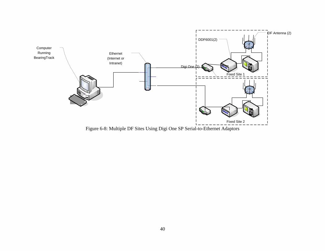
6.6.7 Two DDF6001s and Receivers Connected to PC Using an Ethernet or Internet Connection The PC connects to an Ethernet using a standard network interface card (NIC) that is built into most modern PCs. Port #0 of each DDF6001 is connected to a Digi One SP serial-to-Ethernet adaptor. . ICOM receivers are connected to each remote DDF6001 via Port #1 (J4) or AOR receivers are connected to each remote DDF6001 via Port #2 (J2). Each DDF6001 and ICOM receiver must have different CIV addresses. Note that CIV protocol must be used when a radio modem provides remote operation. If a particular site does not use a CIV receiver, a spare Switchcraft type 750 plug must be inserted into the DDF6001 J4 to cause the DF to operate with CIV protocol. If AOR receivers are used blank CIV cable connector (Switchcraft type 750) must be plugged into the CIV port (J4) and the DDF6001 automatically sets the receiver CIV addresses to the address of the DF plus 32 (default address 33). Figure 6-8 shows a typical arrangement including the wiring needed to connect with the Digi One SP adaptors. Refer to our application note at http://www.dopsys.com/Digi1.htm for more information on configuring the Digi One devices.

29
6.6.8 Other Networking Options There are a number of other ways to network direction finder sites including ways that allow multiple PCs to simultaneously access all sites in a DF network. Please see the application notes on our web site, http://www.dopsys.com/appnotes.htm, for the other options in networking DDF6001 sites.
6.6.9 Command Interlock Beginning with firmware version 4.04, all serial commands except for commands 0, 15 and 16 require that the CAL flag be first enabled. This interlocking feature was added to reduce the probability of a parameter being changed due to a bit error on the serial input. As an example, to change the number of averages to 1, first send command 15 (cal flag = ON), and then send command 1 (set number of averages = 1). The direction finder will automatically turn the cal flag OFF after receiving the second command.

30
Table 6-1
DDF6001 Serial Command List All serial commands except for commands 0, 15 and 16 require that the CAL flag be first
enabled Command Number
Description of Command. Default values shown in bold.
0
Request bearing data
1
Number of averages = 1
2
Number of averages = 2
3
Number of averages = 4
4
Number of averages = 10
5
Number of averages = 20
6
Sweep rate = 0
7
Sweep rate = 300
8
Sweep rate = 600
9
Sweep rate = 1200
10
Sweep rate = 2400
11
Attenuator = ON
12
Attenuator = OFF
13
DF mode = GATED PULSE
14
DF mode = CONTINUOUS
15
Cal flag = ON
16
Cal flag = OFF
17
Cal bearing to zero
18
Cal S-meter to zero
19
Cal S-meter to nine
20
Intensity = BRIGHT
21
Intensity = DIM
22
Port1&2 baud rate = 1200
23
Port1&2 baud rate = 2400
24
Port1&2 baud rate = 4800
25
Port1&2 baud rate = 9600

31
26 Port1&2 data bits = 7 27
Port1&2 data bits = 8
28
Port1&2 stop bits = 1
29
Port1&2 stop bits = 2
30
Port1&2 parity = NONE
31
Port1&2 parity = EVEN
32
Port1&2 parity = ODD
33 through 239
Calibrate the bearing to the value given by the command number - 33. For example, command 33 calibrates the bearing to 0 degree.
240 through 255
These commands are not allowed because of conflicts with the CIV control characters.
256 through 408
Calibrate the bearing to the value given by the command number - 49. For example, command 256 calibrates the bearing to 207 degrees.
409 through 495
Not defined.
496 through 511
These commands are not allowed because of conflicts with the CIV control characters.
512 through 670
Set the address of the DDF6001 used for CIV communications to the value of the command - 511. For example, command 512 sets the address to 1.
671
Use Port #2 for DDF5921 Display
672
Use ICOM receiver
673
Use AOR receiver
674 through 751
Not defined.
752 through 767
These commands are not allowed because of conflicts with the CIV control characters.
768 through 899
Not defined.
890 through 920
Set the bearing stability threshold used in the continuous mode to the value given by the (command number – 890)/20. For example, command 896 sets the threshold to 0.3 radians. This is the default value.
921 through 940
Not defined.
941
Set direction to CW in Gated Pulse Mode.
942
Set direction to CCW in Gated Pulse Mode.
943
Send DF Parameters
944 through 976
Not defined.
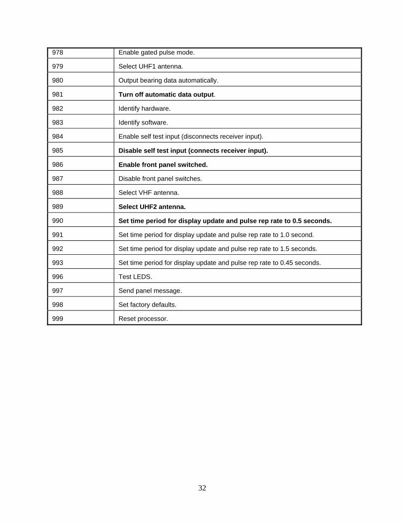
977
Enable sync pulse mode.
32
978 Enable gated pulse mode. 979
Select UHF1 antenna.
980
Output bearing data automatically.
981
Turn off automatic data output.
982
Identify hardware.
983
Identify software.
984
Enable self test input (disconnects receiver input).
985
Disable self test input (connects receiver input).
986
Enable front panel switched.
987
Disable front panel switches.
988
Select VHF antenna.
989
Select UHF2 antenna.
990
Set time period for display update and pulse rep rate to 0.5 seconds.
991
Set time period for display update and pulse rep rate to 1.0 second.
992
Set time period for display update and pulse rep rate to 1.5 seconds.
993
Set time period for display update and pulse rep rate to 0.45 seconds.
996
Test LEDS.
997
Send panel message.
998
Set factory defaults.
999
Reset processor.

33

34

35

36

37

38
`
Computer Running
BearingTrack
Serial ExpanderDDF6077
DF Antenna (2)
Receiver (2)
DDF6001(2)
Modems (2) Fixed Site 1
Phone Line (2)
Figure 6-6: Using Networking Multiple Direction Finder Sites Using Telephone Modems and a DDF6077 Serial Expander

39
Figure 6-7: Multiple DF Sites Using DataRadio Integra Radio Modems
40
`
Computer Running
BearingTrack
DF Antenna (2)
DDF6001(2)
Fixed Site 2
Fixed Site 1
Ethernet(Internet or
Intranet)Digi One (2)
Figure 6-8: Multiple DF Sites Using Digi One SP Serial-to-Ethernet Adaptors

41
7.0 Test Software The DDF6001 includes a CD containing several Windows software programs. MapFix is used to prepare bit mapped images for use with BearingTrack, WinRDFCMD is used to set up and test the system, BearingTrack is used to control one or more direction finders in a network, and BearingServer is used to place a direction finder on an Internet or Intranet for remote access. A separate manual is supplied that covers the operation of the Windows Software.

42
8.0 Servicing
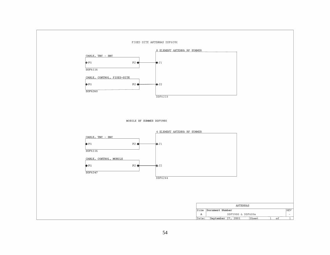
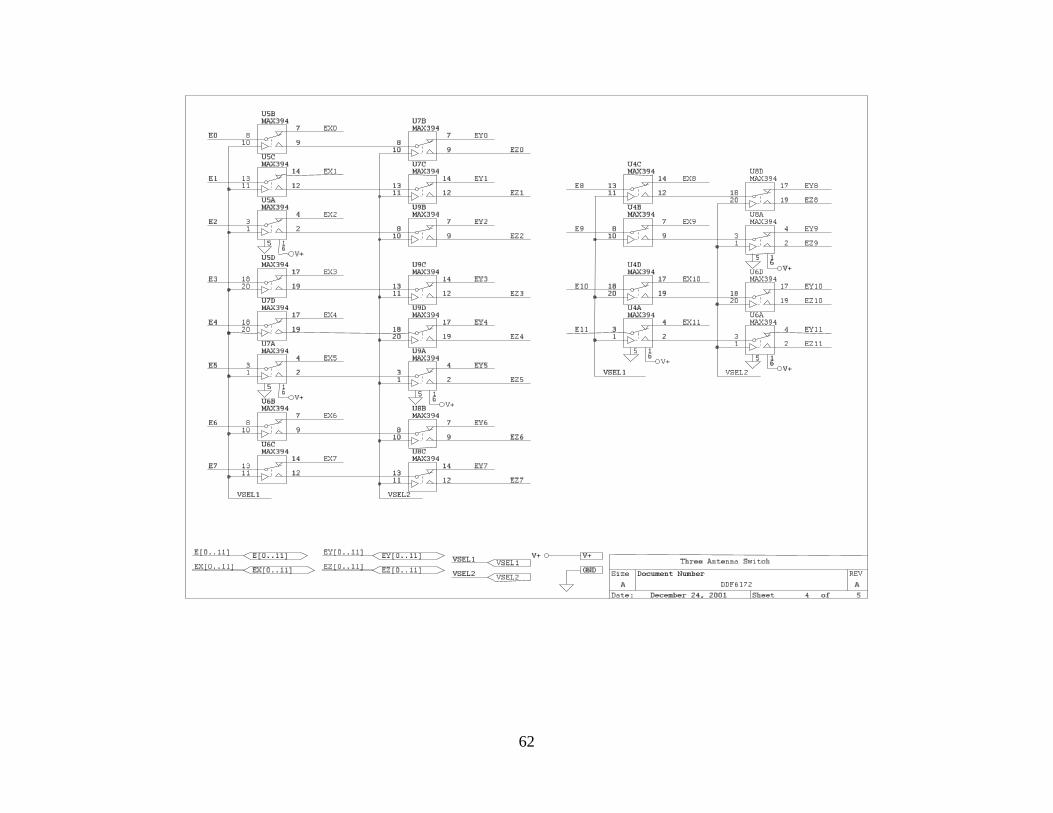
8.1 Schematics A complete set of schematics is provided at the end of this section as an aid to troubleshooting and to clarify interfaces. Because the DDF6001 is a microprocessor-based system that uses high-density surface mount technology in the RF summer/antenna, it is recommended that the unit be returned to the factory for repair. The only exception is for upgrading of the program EPROM that is described below. The circuitry used in the DDF6001 is susceptible to electrostatic discharge. Observe proper ESD precautions when servicing the unit. Overseas customers should refer to the relevant Doppler Distributor.
8.2 EPROM replacement Remove the top cover by removing the (23) black 4-40 screws on the top, sides and back of the unit. Tip the top cover up and disconnect the speaker leads so the cover can be removed completely. Replace the EPROM U123 using proper IC removal and insertion tools and observe electrostatic discharge precautions. Reconnect the speaker leads and replace the top cover using the black 4-40 screws.

43

44

45

46

47

48

49

50

51

52

53
54
55

56

57
58

59

60
DDF6173A Serial Expander

61
62

63

64

65