series 530 horizontal sealant tester - applied test systems › wp-content › uploads › 2019 ›...
TRANSCRIPT

Series 530 Horizontal Sealant Tester
INSTRUCTION MANUAL
This manual contains important operating and safety information. Carefully read and understand the contents of this manual prior to the operation of this equipment.
www.atspa.com
MAN - Series 530 Horizontal Sealant Tester - REV: 02

REVISED MARCH 2019
Information in this document is subject to change without notice and does not represent a commitment on the part of Applied Test Systems (ATS).
© Copyright Applied Test Systems 2018
For assistance with set-up or operation, contact the ATS service department. Please have this manual and product serial number available when you call.
Telephone: +1-724-283-1212.
MAN - Series 530 Horizontal Sealant Tester - REV: 02
MAN - Series 530 Horizontal Sealant Tester - REV: 02 i
Manual Contents
A. Introduction ...................................................................................................................................1
A.1 Unpacking ......................................................................................................................................................1A.2 Warranty Information .....................................................................................................................................1A.3 After-Sale Support .........................................................................................................................................1
B. Safety .............................................................................................................................................2
B.1 For Owners, Operators, and Maintenance ....................................................................................................2B.2 Safety Instructions .........................................................................................................................................2B.3 Cautions ........................................................................................................................................................3B.4 Warnings........................................................................................................................................................3
C. System Overview ..........................................................................................................................4
C.1 General Product Description .........................................................................................................................4C.2 Product Specifications ..................................................................................................................................4
D. Installation .....................................................................................................................................5
D.1 General Installation ........................................................................................................................................5D.2 Setup for Cold Temperature Testing .............................................................................................................5D.3 Setup Remote Communication (Optional) ....................................................................................................5
E. Software Overview .......................................................................................................................7
E.1 Software Map .................................................................................................................................................7E.2 Main Screen ..................................................................................................................................................8E.3 Alarm Screen ...............................................................................................................................................11E.4 Language Screen ........................................................................................................................................12E.5 Program Screen ..........................................................................................................................................12
New Program Button .............................................................................................................................13Function Drop-down .............................................................................................................................13Program Steps Data Section .................................................................................................................14Name Field ............................................................................................................................................14Backup Button .......................................................................................................................................14Restore Button ......................................................................................................................................14Nest Goto Step Commands ..................................................................................................................14Do Not Turn off Temperature at End of Program .................................................................................15Program Log Button ..............................................................................................................................15Done Button ..........................................................................................................................................15
MAN - Series 530 Horizontal Sealant Tester - REV: 02ii
E.6 Program Log Screen ...................................................................................................................................15Cyclic Count Field .................................................................................................................................16Goto Count Field ...................................................................................................................................16Elapsed Time Field ................................................................................................................................16Delete All Log Data Button ....................................................................................................................17Backup All to USB Button .....................................................................................................................17Month, Day, Year, Hour, Minute, and Second Fields .............................................................................17Done Button ..........................................................................................................................................17
E.7 New HMI Software ......................................................................................................................................17
F. Operation .....................................................................................................................................19
F.1 Test Frame ....................................................................................................................................................19F.2 Running a Test .............................................................................................................................................19F.3 Unloading Specimens ..................................................................................................................................19F.4 Operation with Roofing Material Test Fixture (Optional) ..............................................................................19
G. Troubleshooting .........................................................................................................................21
G.1 Preface ........................................................................................................................................................21G.2 Drawhead Alignment Troubleshooting ........................................................................................................21
H. Maintenance ................................................................................................................................25
H.1 Checking Belt Tension .................................................................................................................................25
Appendix A: Warranty ...................................................................................................................26
Appendix B: Image Glossary .........................................................................................................27

MAN - Series 530 Horizontal Sealant Tester - REV: 02 | A. Introduction 1
A. Introduction
A.1 Unpacking
Retain all cartons and packing materials until the unit is operated and found to be in good condition. If damage has occurred during shipping, notify Applied Test Systems (ATS) and the carrier immediately. If it is necessary to file a damage claim, retain the packing materials for inspection by the carrier.
A.2 Warranty Information
All new ATS systems are shipped with a warranty. Units have a warranty against defective parts and workmanship for one full year from the date of shipment. Please see APPENDIX A of this manual for complete details on the warranty.
A.3 After-Sale Support
If there are any questions concerning the operation of the unit or software, contact the ATS Service Department at +1-724-283-1212. Before calling, please obtain the software revision number from the main screen and the serialnumber from the unit’s data tag. A sample data tag is illustrated in Figure A.1, and can be completed with the unit’sinformation for easy reference. Please be prepared to give a complete description of the problem to the ATS ServiceDepartment.
Figure A.1 - ATS Sample Data Tag

MAN - Series 530 Horizontal Sealant Tester - REV: 02 | B. Safety2
B. Safety
B.1 For Owners, Operators, and Maintenance
All ATS equipment is designed to be operated with the highest level of safety. This manual uses note, caution, and warning symbols throughout to draw your attention to important operational and safety information.
Read and understand all instructions and safety precautions listed in this manual before installing or operating your unit. If you have any questions regarding operation of the unit or instructions in this manual, contact the ATS Service Department at +1-724-283- 1212.
In addition to the safety warnings listed on the equipment, warnings are posted throughout this manual. Read and follow these important instructions. Failure to observe these instructions can result in permanent damage to the unit, significant property damage, personal injury or death.
Read Operator’s Manual
General Danger
Protective Earth (Ground)
Electrical Shock/Electrocution
Finger Crush
B.2 Safety Instructions
1. Thoroughly understand the safety features and operation of the equipment. This manual will provide operators with safety concerns and general procedures. Be familiar with correct operating principles and use good judgement. Also refer to the appropriate manuals for system component safety instructions and operating procedures.
2. Disconnect electrical power before changing the specimen and performing maintenance work. Failure to disconnect power may result in personal injury.
3. Before applying power to the tester, replace all covers. Covers are designed to protect equipment and personnel. Do not operate the tester without the appropriate covers in place.

MAN - Series 530 Horizontal Sealant Tester - REV: 02 | B. Safety 3
B.3 Cautions
The following statements are CAUTION statements. These statements alert the operator to conditions that may damage equipment. Operators must be aware of these conditions in order to ensure safe operation of the equipment.
CAUTION: Installation of electrical device must be accomplished by qualified personnel and done in accordance with any current local and national codes.
CAUTION: The Series 530 must be grounded and wired in accordance with national and local electrical code requirements.
CAUTION: Before energizing the electrical power to the Series 530, place all controls in the OFF position.
B.4 Warnings
The following statements are WARNING statements. Unlike caution statements, warning statements alert the operator to conditions that may injure personnel. Operators must be aware of these conditions in order to prevent injuries that may occur while operating this equipment.
WARNING: Obey electrical code requirements. The control system must be wired and grounded in accordance with national and local electrical code requirements.
WARNING: Unpack, install, and operate on a stable surface.
MAN - Series 530 Horizontal Sealant Tester - REV: 02 | C. System Overview4
C. System Overview
C.1 General Product Description
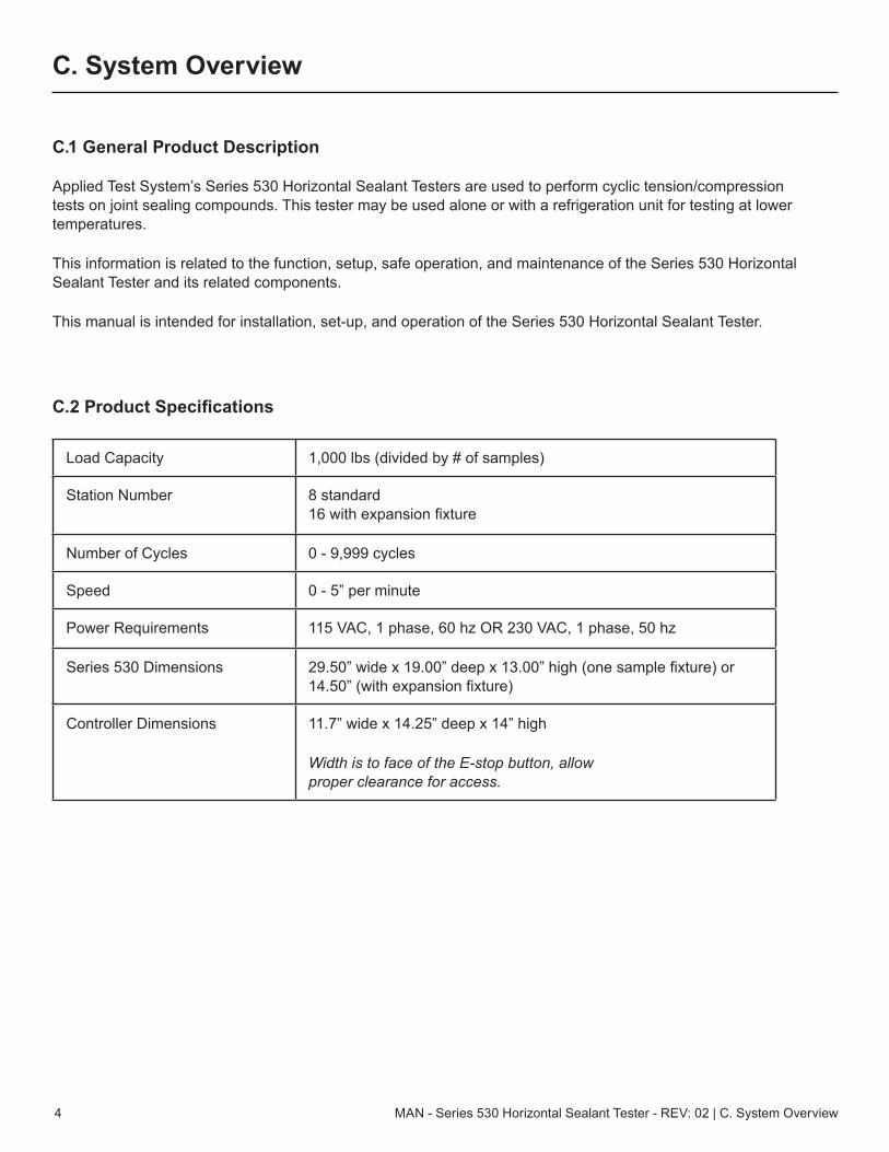
Applied Test System’s Series 530 Horizontal Sealant Testers are used to perform cyclic tension/compression tests on joint sealing compounds. This tester may be used alone or with a refrigeration unit for testing at lower temperatures.
This information is related to the function, setup, safe operation, and maintenance of the Series 530 Horizontal Sealant Tester and its related components.
This manual is intended for installation, set-up, and operation of the Series 530 Horizontal Sealant Tester.
C.2 Product Specifications
Load Capacity 1,000 lbs (divided by # of samples)
Station Number 8 standard 16 with expansion fixture
Number of Cycles 0 - 9,999 cycles
Speed 0 - 5” per minute
Power Requirements 115 VAC, 1 phase, 60 hz OR 230 VAC, 1 phase, 50 hz
Series 530 Dimensions 29.50” wide x 19.00” deep x 13.00” high (one sample fixture) or 14.50” (with expansion fixture)
Controller Dimensions 11.7” wide x 14.25” deep x 14” high
Width is to face of the E-stop button, allow proper clearance for access.

MAN - Series 530 Horizontal Sealant Tester - REV: 02 | D. Installation 5
D. Installation
D.1 General Installation
The following procedure describes how to position, connect, and power the Series 530 Horizontal Sealant Tester.
1. Carefully remove the shipping crate and packing materials from the tester. Do not discard the packing materials until all items on the invoice have been accounted for.
2. Remove the testing machine and control cabinet from the shipping pallet and position them in the desired location. Adjust the isolator mounts to level the testing machine and provide even support to the test frame.
3. Connect the cable between the testing machine and control cabinet. The distance between the control cabinet and tester is limited by the length of the control cable. Additional cables can be obtained by contacting ATS.
4. If necessary for testing, connect the temperature controller and the optional freezer unit, as described in Section D.2.
5. Provide electrical power with ground according to the power requirements found on the tester’s data label.
CAUTION: Before connecting the Series 530 to a source of electricity, turn off all power switches on electrical components and place all controls in the “OFF” or “NEUTRAL” position.
6. Once the Series 530 is connected, turn the equipment on by flipping the power switch on the back of the controller to the “ON” position.
D.2 Setup for Cold Temperature Testing
Cold temperature testing with an additional freezer unit is an optional feature of the Series 530 Horizontal Sealant Tester. If necessary for your testing, follow the additional steps below.
1. Place the testing machine on the freezer’s stainless steel shelf. Connect the machine cable to the twist lock plug inside of the freezer.
D.3 Setup Remote Communication (Optional)
The Series 530 Horizontal Sealant Tester is equipped with the ability to connect remotely, and is ready to be connected as soon as it is removed from the crate and powered on. All you will need is an internet connection and a VNC Viewer program. Follow the instructions below to connect your equipment.
1. Ensure that the Series 530 is powered on and connected. The Main Screen should be displayed on the controller.

MAN - Series 530 Horizontal Sealant Tester - REV: 02 | D. Installation6
3. In the IP Address Field, enter the IP Address of the Ethernet port on the back of the Series 530 Horizontal Sealant Tester control box.
3. Using any downloaded VNC Viewer program, users can now login to view their equipment remotely.

MAN - Series 530 Horizontal Sealant Tester - REV: 02 | E. Software Overview 7
E. Software Overview
E.1 Software Map
Figure E.1 illustrates the proper navigation of the Series 530 Sealant Tester’s software screens.
Figure E.1: Series 530 Sealant Tester Software Map
Main Screen
Backup Program
Language
Programming
Temp Setpoint
Temp Enable
Data
Function
540 Menu Flow
Return CrossheadOnly when not in cycle
Displacement Units
Fast Jog Speed
Stop CycleOnly when in cycle
Start Cycle
Drive Enable/Disable Jog Speed
Temp Units
Restore Program
Reset AlarmAlarm
IP Address
Steps
Jog OpenOnly when not in cycle
Jog CloseOnly when not in cycle
High Jog SpeedOnly when not in cycle
Only when not in cycle
Only when not in cycle
Only when not in cycle
Hold CycleOnly when in cycle
Only with Temp Option
Only with Temp Option
Only when not in cycle
Only when not in cycle
Only when not in cycle
Only when not in cycle
Only when not in cycle
Only when not in cycle
Only when not in cycle
Program Log
Save Logs to USB
Set Date / Time
Delete Logs
8 MAN - Series 530 Horizontal Sealant Tester - REV: 02 | E. Software Overview
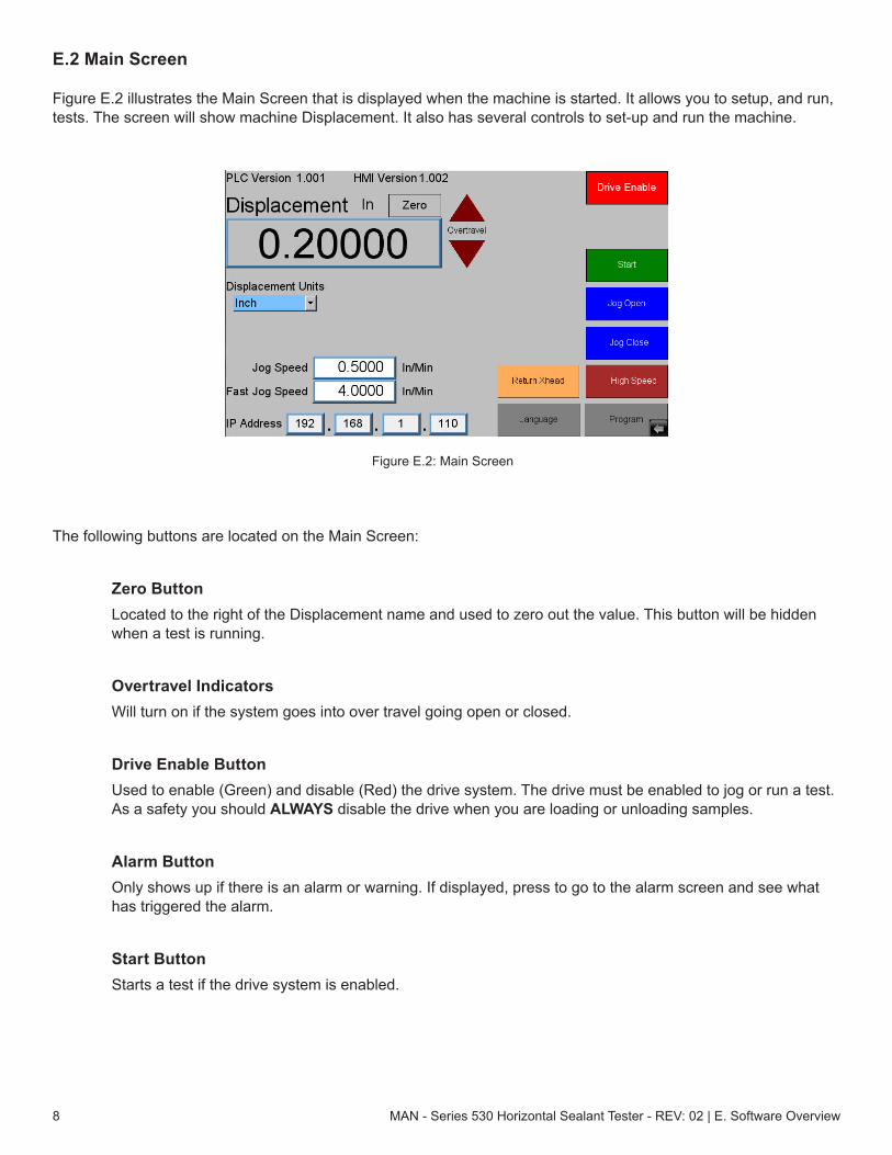
E.2 Main Screen
Figure E.2 illustrates the Main Screen that is displayed when the machine is started. It allows you to setup, and run, tests. The screen will show machine Displacement. It also has several controls to set-up and run the machine.
The following buttons are located on the Main Screen:
Zero ButtonLocated to the right of the Displacement name and used to zero out the value. This button will be hidden when a test is running.
Overtravel IndicatorsWill turn on if the system goes into over travel going open or closed.
Drive Enable ButtonUsed to enable (Green) and disable (Red) the drive system. The drive must be enabled to jog or run a test. As a safety you should ALWAYS disable the drive when you are loading or unloading samples.
Alarm ButtonOnly shows up if there is an alarm or warning. If displayed, press to go to the alarm screen and see what has triggered the alarm.
Start ButtonStarts a test if the drive system is enabled.
Figure E.2: Main Screen

MAN - Series 530 Horizontal Sealant Tester - REV: 02 | E. Software Overview 9
Jog Open and Close ButtonsWill jog the machine in the desired direction at the currently selected jog speed.
Return Xhead ButtonSend the crosshead back to the zero displacement position at the current jog speed if the drive system is enabled. Please note that if you press the “Return Xhead” button and the system is moving to the zero position, pressing it again will stop it.
High Speed ButtonTurns fast jogging speed on and off. See Fast Jog Speed Field note about auto shut-off of fast speed.
Program ButtonTakes you to the program edit screen. When the system is running a test this button is hidden so that changes cannot be made.
Language ButtonUsed to access the Language Screen where you can change the text language for the system. When the system is running a test this button is hidden and changes cannot be made.
Displacement UnitsAllow the system displacement to show and be programed in English (In) or Metric (mm) units. This is hidden if the system is running a test.
Jog Speed FieldShows the speed that the system will travel for normal jog, when the jog buttons or the “Return Xhead” are pressed. This is hidden if the system is running a test.
Fast Jog Speed FieldShows the speed that the system will travel for fast jog, when the jog buttons or the “Return Xhead” button are pressed. This is hidden if the system is running a test.
NOTE: Fast jog speed is used instead of the normal speed if the “High Speed” button has been pressed. If the system is in fast jog the “High Speed” button will light up. You can turn off fast jog by pressing the button again, or fast jog will time out and return to the normal jog speed after 15 seconds if the system is not moving. If the system is moving (Jog or Return Xhead), the speed will return to normal after 15 seconds and after the movement stops.
IP Address FieldUsed to allow someone at a remote location to monitor the system using a VNC viewer program. It is also used for data logging using other programs. This is hidden if the system is running a test.
10 MAN - Series 530 Horizontal Sealant Tester - REV: 02 | E. Software Overview
Temperature UnitsAllow the system temperature to show and be programed in English (°F) or Metric (°C) units. This will only be displayed if the system has a temperature control option and is not running a test.
Current TempDisplays the current chamber temperature. This will only be displayed if the system has a temperature control option.
Temp SetpointManual set point for the chamber temperature. This will only be displayed if the system has a temperature control option and no test is running.
Temp EnableAllows the operator to manually turn the chamber temperature control on and off. This will only be displayed if the system has a temperature control option and no test is running.
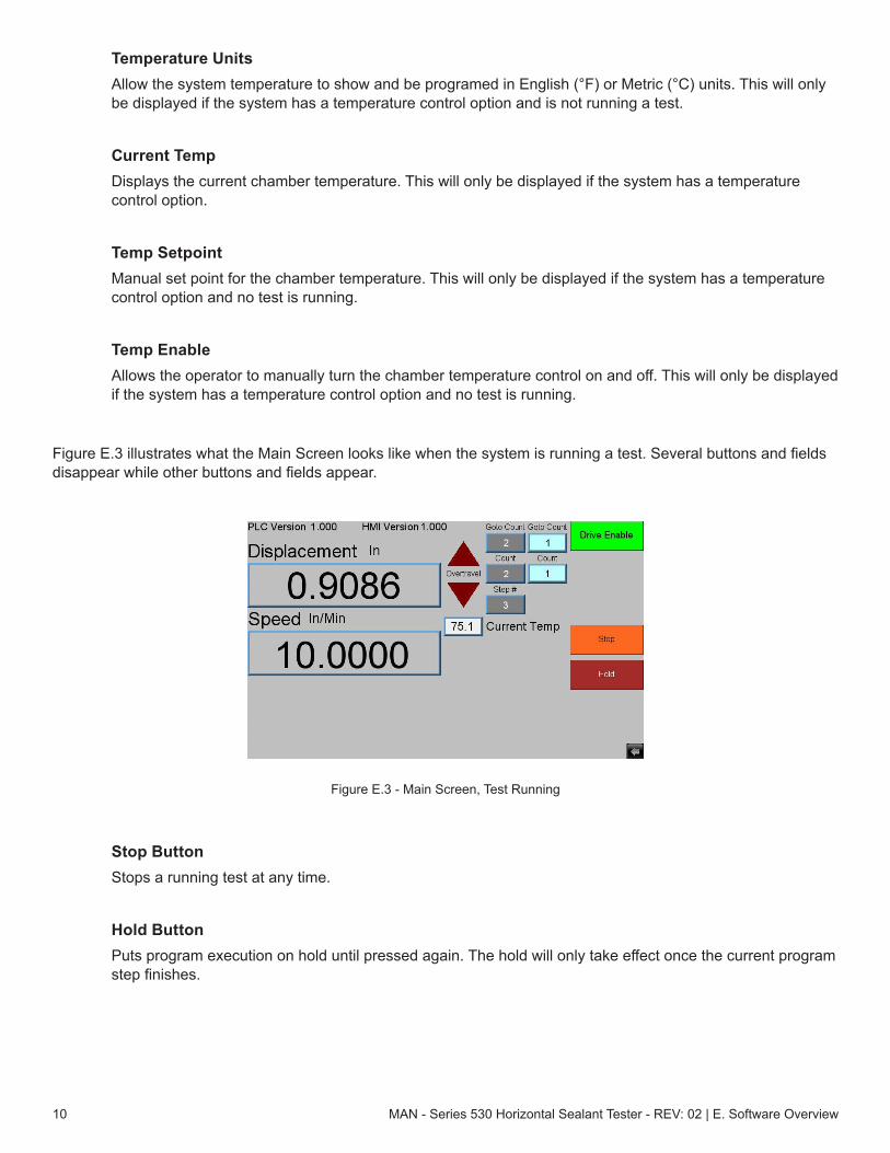
Figure E.3 illustrates what the Main Screen looks like when the system is running a test. Several buttons and fields disappear while other buttons and fields appear.
Stop ButtonStops a running test at any time.
Hold ButtonPuts program execution on hold until pressed again. The hold will only take effect once the current program step finishes.
Figure E.3 - Main Screen, Test Running

MAN - Series 530 Horizontal Sealant Tester - REV: 02 | E. Software Overview 11
Speed DisplayDisplays the last commanded speed of the system.
Step # FieldDisplays the step number of the program that is currently being executed.
Count FieldsOnly show up if the current program step is a “Cycle Position” move. The gray field is the total number of cycles programed. The light blue field shows how many cycles have been executed so far.
Time FieldsIf the current program step is a “Hold” the “Count Fields” will be replaced with “Time Fields”. The gray field is the total amount of time in minutes programed. The light blue field is how much time has been executed so far in minutes.
Goto Count FieldsOnly show up if the program is in a Goto loop. The gray field is the total number of returns programed. The light blue field is how many have been executed so far. This will only show up if you do not have nested Goto loops.
E.3 Alarm Screen
Figure E.4 illustrates the Alarm Screen. It is shown anytime the “Alarm” button is pressed on the Configure or Main Screen, and displays the current alarm(s) or warning(s) that triggered the button’s appearance.
The Alarm Screen shows all current alarms (in Red) and warnings (in Yellow). Users can attempt to reset these with the “Reset” button. Some alarms will go away automatically when the alarm condition goes away. However, some
Figure E.4: Alarm Screen

12 MAN - Series 530 Horizontal Sealant Tester - REV: 02 | E. Software Overview
will not go away until a power cycle. The “Done” button will return you to the previous screen.
E.4 Language Screen
Figure E.6 illustrates the Language Screen. It is shown anytime the “Language” button is pressed on the Configure Screen.
To change the language the system is using, simply press the flag of the language you wish to use.
Pressing the “Done” button will return you to the Configure Screen.
E.5 Program Screen
Figure E.5: Language Screen
Figure E.6: Program Screen
MAN - Series 530 Horizontal Sealant Tester - REV: 02 | E. Software Overview 13
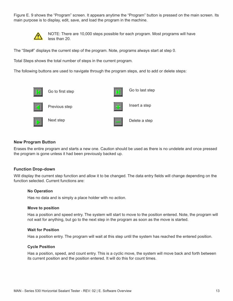
Figure E. 9 shows the “Program” screen. It appears anytime the “Program” button is pressed on the main screen. Its main purpose is to display, edit, save, and load the program in the machine.
NOTE: There are 10,000 steps possible for each program. Most programs will have less than 20.
The “Step#” displays the current step of the program. Note, programs always start at step 0.
Total Steps shows the total number of steps in the current program.
The following buttons are used to navigate through the program steps, and to add or delete steps:
Go to first step
Previous step
Next step
New Program ButtonErases the entire program and starts a new one. Caution should be used as there is no undelete and once pressed the program is gone unless it had been previously backed up.
Function Drop-down Will display the current step function and allow it to be changed. The data entry fields will change depending on the function selected. Current functions are:
No OperationHas no data and is simply a place holder with no action.
Move to positionHas a position and speed entry. The system will start to move to the position entered. Note, the program will not wait for anything, but go to the next step in the program as soon as the move is started.
Wait for PositionHas a position entry. The program will wait at this step until the system has reached the entered position.
Cycle PositionHas a position, speed, and count entry. This is a cyclic move, the system will move back and forth between its current position and the position entered. It will do this for count times.
Go to last step
Insert a step
Delete a step

14 MAN - Series 530 Horizontal Sealant Tester - REV: 02 | E. Software Overview
Goto StepHas a step number and count entry. The step number must be a previous step. This is a loop control. The program will jump back to the entered step and execute the program from there to the goto for count times. Then it will move on to the next step of the program. Note, if the step number entered is not a previous step the program will jump over a section of program not executing it and the count will not be used. Also, remember that the code has executed once before it gets to the goto command so if you wish to execute a block of code a certain number of times, enter one less in the count.
HoldHas a time entry. The program will wait at this step until the entered time has expired.
Set TemperatureHas a temperature and rate entry. This command will set the temperature control to the entered temperature at the ramp rate entered and move on to the next step. Note, the program will not wait for anything, but go to the next step in the program as soon as the temperature is set. This command will only be displayed if the system has the temperature control option.
Wait for TemperatureHas a temperature entry. The program will wait at this step until the system has reached the entered temperature. This command will only be displayed if the system has the temperature control option.
Program Steps Data SectionAllows you to backup and restore the program to a USB flash drive. This may be useful in the event of a hardware failure, or if you wish to have multiple programs to run on this machine. The “Idle” to the right of the section name will change to “Busy” when the system is accessing the flash drive.
Name FieldUsed to name the file that is to be backed up to or restored from the USB flash. The name may include a path if desired.
Backup ButtonUsed to save the program data from the machine to the flash drive. Note, this button will only be displayed if a flash drive is plugged in.
Restore ButtonUsed to restore the program data from the flash drive to the machine. Note, this button will only be displayed if a flash drive is plugged in. The white box to the right of the name field will display the file names of the programs already stored on the flash. This is where you select a file to be restored.
Nest Goto Step CommandsCan be checked if you wish to nest goto commands. They may be nested as deep as you like but the “Goto Count” on the main screen will not be displayed when a test is running.

MAN - Series 530 Horizontal Sealant Tester - REV: 02 | E. Software Overview 15
Do Not Turn off Temperature at End of Program May be checked if you have many samples to run and wish the chamber to stay at temperature. Otherwise the control system will shut down at the end of a test. This will only be displayed if the system has the temperature control option.
Program Log ButtonWill take you to the Program Log Screen.
Done ButtonWill return you to the Main Screen.
Anytime you insert a flash drive you will see the screen in Figure E.7.
If you are just inserting a flash drive with machine programs on it just press “Cancel”. You would only need the other buttons if you are updating the HMI software.
E.6 Program Log Screen
Figure E.8 shows the Program Log Screen. It is displayed any time the “Program Log” button is pressed on the Program Screen. Its main purpose is to display the program log of programs run on the machine.
The data display in the top left corner will show the program log for the selected log file. The top of the display will be the program start point, and the bottom of the display will be the end of the program or where program execution stopped.
The first two fields are date and time and is logged as each program step is executed.
Figure E.7: Flash Drive Pop-Up
Figure E.8: Program Log Screen

16 MAN - Series 530 Horizontal Sealant Tester - REV: 02 | E. Software Overview
The next field is the program step number.
The next field is the program function for that step. The following is a list of these functions.
Program function numbers:
0 No Operation1 Move to Position2 Wait for position3 Cyclic Position4 Goto Step5 Hold6 Set Temperature7 Wait for Temperature
Cyclic Count FieldShows the current count for a “Cyclic Position” move. The cyclic position command will create a log entry for each cycle finished. If your current function is not 3, this value is not updated and has no meaning.
Goto Count FieldShows the current count for a “Goto Step” loop. If you are not in a goto loop, this value is not updated and has no meaning.
Elapsed Time FieldShows the amount of time that has elapsed since the start of a “Hold” command. The hold command will create a log entry according to the table below. If your current function is not 5, this value is not updated and has no meaning.
To keep the program from logging hundreds of points during a hold, it is set up to log at different times depending on the hold time.
Hold Time (min) Log Frequency
Under 1 every second
1+ to 10 every 30 seconds
10+ to 100 every minute
100+ to 1000 every 30 minutes
1000+ to 5000 every hour
5000+ to 10000 every 5 hours
Over 10000 every 10 hours

MAN - Series 530 Horizontal Sealant Tester - REV: 02 | E. Software Overview 17
The field to the top right of the screen is used to select the program log file to display. The log file name is date and time it was created.
Delete All Log Data ButtonAsks you to confirm that you wish to delete all log files on the HMI. If you answer yes then all log data on the HMI will be deleted. Caution should be used as once deleted they are gone and cannot be retrieved.
Backup All to USB ButtonCopies all log files on the HMI to a USB stick.
Month, Day, Year, Hour, Minute, and Second FieldsAllow you to set the current date and time in the HMI. This is used when storing program log data.
Done ButtonWill return you to the “Program” Screen.
Anytime you insert a flash drive you will see the screen show in Figure E.7 (p. 14). If you are just inserting a flash drive to put log files on it, just press “Cancel”. You would only need the other buttons if you are updating the HMI software.
E.7 New HMI Software
Periodically a new software version may come out for the HMI. Below are instructions for downloading the new software. The new version of software must be on the root of a flash drive.
1. Power on the machine.
2. Open USB port cover and install flash drive containing the new version of software into the USB port.
3. When the menu in Figure E.7 appears, choose ‘Download’.
4. Another pop-up menu (Figure E.9) will appear prompting for a password. Using the keyboard displayed on the screen, enter 111111. Check the box that indicates Download Project files and uncheck the boxes that indicate Clear History files and Download History files. Select OK.
5. Next will appear 2 subdirectories (Figure E.10) - pccard and usbdisk. Click usbdisk then click disk_a_1 then click OK.
Figure E.9: Keypad Pop-Up

18 MAN - Series 530 Horizontal Sealant Tester - REV: 02 | E. Software Overview
The necessary files will now be downloaded.
When done, remove the flash drive and replace the USB port cap.
Figure E.10: Subdirectories

MAN - Series 530 Horizontal Sealant Tester - REV: 02 | F. Operation 19
F. Operation
F.1 Test Frame
The test frame is constructed with twin ball screws driven by an electronically controlled servo motor driving the loading crosshead. Fixed stops on the limit switch actuator rod are set at the factory to protect the test frame by limiting crosshead movement. Do not readjust these stops.
F.2 Running a Test
1. Use the jog buttons to position and load samples into the test fixture.
2. Zero the displacement if required.
3. Verify that there are no alarms showing and the drive is enabled, then press the START button.
Pressing the STOP button will stop a test before it finishes.
F.3 Unloading Specimens
1. Place the removal plate on top of the tester and align the four bolt holes. Insert the four hand screws.
2. To remove the specimens, loosen the four captured bolts.
3. Lift with the handles, removing the specimen holders.
4. If necessary, place on a work bench and remove the top plate to gain access to the optional second fixture.
5. Place the specimen holder back in the original location before inserting the pins into the alignment holes.
6. Replace the optional second fixture on top of the first, using the alignment pins to ensure that it is aligned.
F.4 Operation with Roofing Material Test Fixture (Optional)
An optional Roofing Material Test Fixture is available for the Series 530, allowing operators to test polymer-modified bituminous membrane specimens to ASTM D 5849 standards. The same Series 530 software can now provide data on classifying polymer-modified bituminous membranes, based on their performance related to the fatigue conditions to which they are subjected.
To use the Series 530 Roofing Material Test Fixture, follow the instructions below.
1. Remove Sealant test fixture using the removal plate (as described in Section F.3) and set aside.
20 MAN - Series 530 Horizontal Sealant Tester - REV: 02 | F. Operation
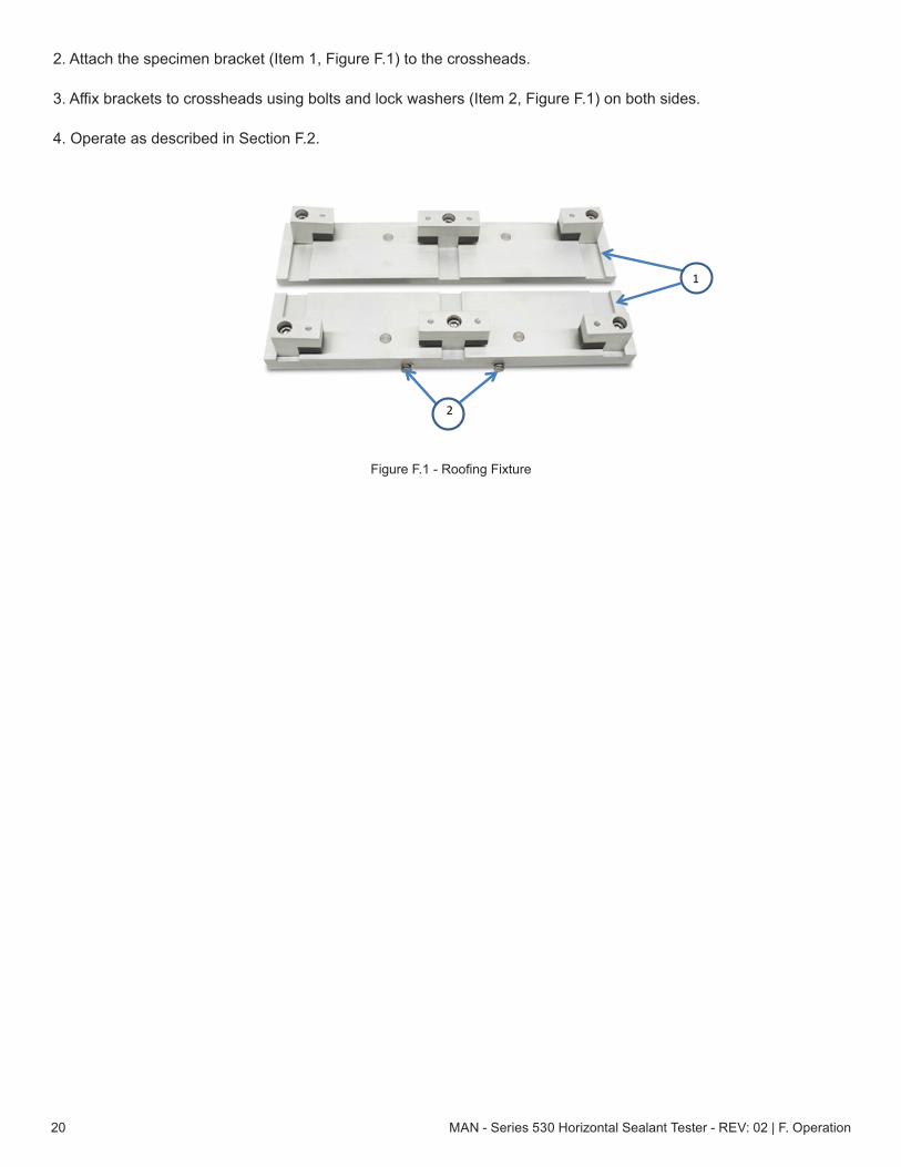
2. Attach the specimen bracket (Item 1, Figure F.1) to the crossheads.
3. Affix brackets to crossheads using bolts and lock washers (Item 2, Figure F.1) on both sides.
4. Operate as described in Section F.2.
Figure F.1 - Roofing Fixture
1
2
MAN - Series 530 Horizontal Sealant Tester - REV: 02 | G. Troubleshooting 21
G. Troubleshooting
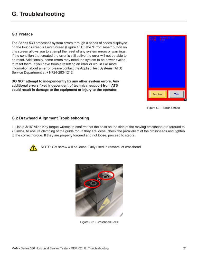
G.1 Preface
The Series 530 processes system errors through a series of codes displayed on the touchs creen’s Error Screen (Figure G.1). The “Error Reset” button on this screen allows you to attempt the reset of any system errors or warnings. If the condition that created the error is still active the error will not be able to be reset. Additionally, some errors may need the system to be power cycled to reset them. If you have trouble resetting an error or would like more information about an error please contact the Applied Test Systems (ATS) Service Department at +1-724-283-1212.
DO NOT attempt to independently fix any other system errors. Any additional errors fixed independent of technical support from ATS could result in damage to the equipment or injury to the operator.
G.2 Drawhead Alignment Troubleshooting
1. Use a 3/16” Allen Key torque wrench to confirm that the bolts on the side of the moving crosshead are torqued to 75 in/lbs, to ensure clamping of the guide rod. If they are loose, check the parallelism of the crossheads and tighten to the correct torque. If they are properly torqued and not loose, proceed to step 2.
NOTE: Set screw will be loose. Only used in removal of crosshead.
Figure G.1 - Error Screen
Figure G.2 - Crosshead Bolts
MAN - Series 530 Horizontal Sealant Tester - REV: 02 | G. Troubleshooting22
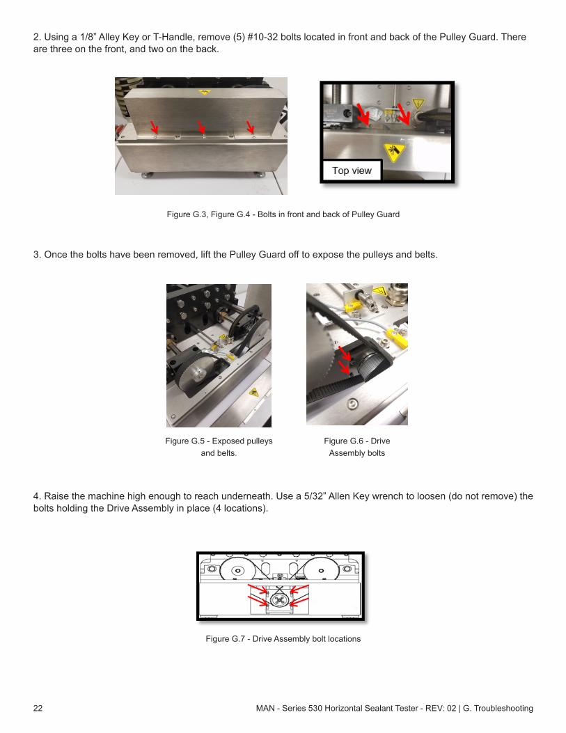
2. Using a 1/8” Alley Key or T-Handle, remove (5) #10-32 bolts located in front and back of the Pulley Guard. There are three on the front, and two on the back.
3. Once the bolts have been removed, lift the Pulley Guard off to expose the pulleys and belts.
4. Raise the machine high enough to reach underneath. Use a 5/32” Allen Key wrench to loosen (do not remove) the bolts holding the Drive Assembly in place (4 locations).
Figure G.3, Figure G.4 - Bolts in front and back of Pulley Guard
Figure G.5 - Exposed pulleys and belts.
Figure G.6 - Drive Assembly bolts
Figure G.7 - Drive Assembly bolt locations

MAN - Series 530 Horizontal Sealant Tester - REV: 02 | G. Troubleshooting 23
5. Lift up on the Drive Assembly and remove the belt from the upper pulleys.
6. Use a 5/16” Allen Key T-Handle wrench to remove the 3/8”-16 bolts that hold down the sealant specimen fixture to the crossheads.
7. Insert two equal length gage blocks between the crossheads to ensure distance is even from side-side. Gage blocks may be 6.50” to 4.00” in length (4.00” gage blocks shown).
Figure G.8 - Remove belt
Figure G.9 - Bolts holding down sealant specimen fixture
Figure G.10 - Gage blocks in place

MAN - Series 530 Horizontal Sealant Tester - REV: 02 | G. Troubleshooting24
8. To adjust pulleys, turn both counterclockwise until they evenly press up against the gage blocks. Ensure there is no binding, which may cause misalignment.
9. Once evenly aligned, reattach belts, apply downward pressure on the drive mounting plate (shown in Figure G.12), and re-tighten the 4 bolts. Check to ensure the alignment didn’t shift, then reassemble the pulley guard. Turn on the machine, and jog the machine open. Remove the gage blocks, then reattach the sealant specimen grip assemlies and reset the Zero position to 0.25” between grips.
Figure G.11 - Adjust pulleys
Figure G.12 - Apply downward pressure on drive mounting plate

MAN - Series 530 Horizontal Sealant Tester - REV: 02 | H. Maintenance 25
H. Maintenance
H.1 Checking Belt Tension
Belt tension should be checked at every calibration (or if movable crosshead is not moving). If the belt is loose, the bolts holding the motor mounting plate will need to be loosened (see Figure H.1), belts re-tensioned (motor plate slid down to apply belt tension), and bolts re-tightened. Non-permanent thread compound, such as Loctite, may be used on the motor plate bolts.
Figure H.1 - Checking Belt Tension

MAN - Series 530 Horizontal Sealant Tester - REV: 02 | Appendix A: Warranty26
Appendix A: Warranty
Your Applied Test Systems product has been manufactured and inspected by experienced craftsmen. Applied Test Systems warrants, for the original purchaser, each product to be free from defects in material and workmanship for a period of thirteen (13) months from date of shipment or twelve (12) months from date of installation - whichever comes first. This warranty does not apply to failures caused by normal usage, misuse, or repair or service by unauthorized personnel, nor does it cover limited life electrical components which deteriorate with age such as tubes, lamps, fuses, and heaters. Load cells are covered for manufactured defects only - incidents of over load or other customer misuse are not covered under warranty. The warranty does not extend to products not manufactured or assembled by Applied Test Systems.
This warranty is expressly limited to the repair, replacement, or adjustment of the product at Applied Test Systems’ option. The product must be returned to the Applied Test Systems factory or an authorized repair center. Applied Test Systems shall not be liable for any labor, transportation, or installation costs that may arise in connection with the product or return.
To obtain warranty service:
1. Applied Test Systems must be promptly notified in writing of the defect.
2. Upon receipt of written authorization, said defective equipment is returned as directed, with transportationcharges prepaid by the buyer and –
3. Applied Test Systems examination of such equipment discloses to its satisfaction that the defect exists andwas not caused by negligence, misuse, improper installation, accident, or unauthorized repair or alteration.
This warranty is in lieu of all other warranties, expressed or implied, including the implied warranty of merchantability or fitness for particular purpose. In no event shall Applied Test Systems be liable for direct, indirect, special, incidental, collateral, or consequential damages.
The aforementioned provisions do not extend the original warranty period of any article that has been either repaired or replaced by Applied Test Systems.
Applied Test Systems reserves the right to change published specifications.
MAN - Series 530 Horizontal Sealant Tester - REV: 02 | Appendix B: Image Glossary 27
Appendix B: Image Glossary
Figure A.1 - ATS Sample Data Tag ................................................................................................................................1Figure E.1: Series 530 Sealant Tester Software Map ....................................................................................................7Figure E.2: Main Screen ................................................................................................................................................8Figure E.3 - Main Screen, Test Running .......................................................................................................................10Figure E.4: Alarm Screen ..............................................................................................................................................11Figure E.5: Language Screen .......................................................................................................................................12Figure E.6: Program Screen .........................................................................................................................................12Figure E.7: Flash Drive Pop-Up ....................................................................................................................................15Figure E.8: Program Log Screen ..................................................................................................................................15Figure E.9: Keypad Pop-Up ..........................................................................................................................................17Figure E.10: Subdirectories ...........................................................................................................................................18Figure F.1 - Roofing Fixture ...........................................................................................................................................20Figure G.1 - Error Screen ..............................................................................................................................................21Figure G.2 - Crosshead Bolts .......................................................................................................................................21Figure G.3, Figure G.4 - Bolts in front and back of Pulley Guard .................................................................................22Figure G.5 - Exposed pulleys and belts. .......................................................................................................................22Figure G.6 - Drive Assembly bolts ................................................................................................................................22Figure G.7 - Drive Assembly bolt locations ...................................................................................................................22Figure G.8 - Remove belt ..............................................................................................................................................23Figure G.9 - Bolts holding down sealant specimen fixture ...........................................................................................23Figure G.10 - Gage blocks in place ...............................................................................................................................23Figure G.11 - Adjust pulleys ...........................................................................................................................................24Figure G.12 - Apply downward pressure on drive mounting plate ................................................................................24Figure H.1 - Checking Belt Tension ...............................................................................................................................25