series 100 single packaged units ypal design...
TRANSCRIPT

PACKAGED ROOFTOP UNITS
INSTALLATION, OPERATION, MAINTENANCE Supersedes 100.50-NOM5 (917) Form 100.50-NOM5 (518)
SERIES 100SINGLE PACKAGED UNITS
YPAL DESIGN LEVEL F
035-21979-003
50 THROUGH 65 TONS
Issue Date: May 23, 2018
LD19892

JOHNSON CONTROLS2
FORM 100.50-NOM5ISSUE DATE: 5/23/2018
This equipment is a relatively complicated apparatus. During rigging, installation, operation, maintenance, or service, individuals may be exposed to certain com-ponents or conditions including, but not limited to: heavy objects, refrigerants, materials under pressure, rotating components, and both high and low voltage. Each of these items has the potential, if misused or handled improperly, to cause bodily injury or death. It is the obligation and responsibility of rigging, instal-lation, and operating/service personnel to identify and recognize these inherent hazards, protect themselves, and proceed safely in completing their tasks. Failure to comply with any of these requirements could result in serious damage to the equipment and the property in
IMPORTANT!READ BEFORE PROCEEDING!
GENERAL SAFETY GUIDELINES
which it is situated, as well as severe personal injury or death to themselves and people at the site.
This document is intended for use by owner-authorized rigging, installation, and operating/service personnel. It is expected that these individuals possess independent training that will enable them to perform their assigned tasks properly and safely. It is essential that, prior to performing any task on this equipment, this individual shall have read and understood the on-product labels, this document and any referenced materials. This in-dividual shall also be familiar with and comply with all applicable industry and governmental standards and regulations pertaining to the task in question.
SAFETY SYMBOLS
The following symbols are used in this document to alert the reader to specific situations:
Indicates a possible hazardous situation which will result in death or serious injury if proper care is not taken.
Indicates a potentially hazardous situa-tion which will result in possible injuries or damage to equipment if proper care is not taken.
Identifies a hazard which could lead to damage to the machine, damage to other equipment and/or environmental pollu-tion if proper care is not taken or instruc-tions and are not followed.
Highlights additional information useful to the technician in completing the work being performed properly.
External wiring, unless specified as an optional connection in the manufacturer’s product line, is not to be connected inside the control cabinet. Devices such as relays, switches, transducers and controls and any external wiring must not be installed inside the micro panel. All wiring must be in accor-dance with Johnson Controls’ published specifications and must be performed only by a qualified electrician. Johnson Controls will NOT be responsible for damage/problems resulting from improper connections to the controls or application of improper control signals. Failure to follow this warn-ing will void the manufacturer’s warranty and cause serious damage to property or personal injury.

JOHNSON CONTROLS 3
FORM 100.50-NOM5 ISSUE DATE: 5/23/2018
CHANGEABILITY OF THIS DOCUMENT
In complying with Johnson Controls’ policy for con-tinuous product improvement, the information con-tained in this document is subject to change without notice. Johnson Controls makes no commitment to update or provide current information automatically to the manual or product owner. Updated manuals, if applicable, can be obtained by contacting the nearest Johnson Controls Service office or accessing the John-son Controls QuickLIT website at http://cgproducts.johnsoncontrols.com.
It is the responsibility of rigging, lifting, and operating/ service personnel to verify the applicability of these documents to the equipment. If there is any question
regarding the applicability of these documents, rig-ging, lifting, and operating/service personnel should verify whether the equipment has been modified and if current literature is available from the owner of the equipment prior to performing any work on the chiller.
CHANGE BARSRevisions made to this document are indicated with a line along the left or right hand column in the area the revision was made. These revisions are to technical in-formation and any other changes in spelling, grammar or formatting are not included.
MANUAL DESCRIPTION FORM NUMBER
Shipping Damage Claims 50.15-NM
Static Pressure Probe Installation Instructions 100.50-N15
High Altitude Accessory Kit Installation Instructions 100.50-N16
Start-Up Guide 100.50-SU5
ASSOCIATED LITERATURE

JOHNSON CONTROLS4
FORM 100.50-NOM5ISSUE DATE: 5/23/2018
NOMENCLATURE
BASE MODEL NUMBER
EXAMPLE -YPAL050NCE46LSFX 1 2 3 4 5 6 7 8 9 10 11 12 13 14 15 16 17BASE PRODUCT TYPE NOMINAL CAPACITY APPLICATION REFRIGERANT VOLTAGE DUCT LOCATIONS DESIGN SPECIAL GAS HEAT CAPACITY
A : Std. Product, Simplicity EliteB : Special Product, Simplicity EliteX : Std. Product, IPUS : Special Product, IPU
B : R-407CC : R-22E : R-410A
5 : 208 / 3 / 60 230 / 3 / 606 : 460 / 3 / 608 : 575 / 3 / 600 : 380 / 3 / 605 : 400 / 3 / 50C : Constant Volume
V : VAV, VFDF : FlexSys
B : Bottom ReturnR : Rear ReturnS : Side Return
C : Cooling OnlyN : Staged Natural Gas HeatG : Staged Natural Gas Heat SS HXM : Full Modulating Gas HeatF : Full Modulating Gas Heat SS Staged HXE : Electric HeatH : Hot Water HeatS : Steam Heat
L : Scroll
P : Packaged Rooftop
A : Air-Cooled
Y : YORK
0101
5566
0000
2
4544
B : Bottom SupplyL : Left SupplyR : Right Supply
F : Revision Level F (initial)
N : No Gas HeatL : Low (375 MBH)M : Med (750 MBH)H : High (1125 MBH)

JOHNSON CONTROLS 5
FORM 100.50-NOM5 ISSUE DATE: 5/23/2018
TABLE OF CONTENTSSECTION 1 – INTRODUCTION ..............................................................................................................................15
Ecological And Economical Design ................................................................................................................15Cooling and Heating ..............................................................................................................................15Indoor Air Quality (IAQ) ..........................................................................................................................15Premium-Efficiency Motors ...................................................................................................................15Modulating Gas Heat .............................................................................................................................15Power Phase Monitor ............................................................................................................................15
Condensing Section .......................................................................................................................................15Scroll Compressors ...............................................................................................................................15Multiple Compressor Staging ................................................................................................................16Compressor Circuiting ..........................................................................................................................16Compressor Sound Blankets .................................................................................................................16Replaceable Core Filter Driers ..............................................................................................................16Low Ambient Operation .........................................................................................................................16Condenser Fan Motors ..........................................................................................................................16Condenser Coils ....................................................................................................................................16Condenser Coil Protection ....................................................................................................................16Hot Gas Reheat .....................................................................................................................................16
Heating Section ..............................................................................................................................................16Gas Heat Design And Control Options ..................................................................................................16Staged Gas Heat ...................................................................................................................................16Electric ...................................................................................................................................................16
Air Management .............................................................................................................................................16DWDI Airfoil Fans ..................................................................................................................................17Building Pressure Control ......................................................................................................................17Low Sound Options ...............................................................................................................................17Variable Frequency Drives ....................................................................................................................17Fan Spring Isolation ..............................................................................................................................17
Controls ..........................................................................................................................................................17Rooftop Controller ..................................................................................................................................17BACnet .................................................................................................................................................17
Indoor Air Quality ...........................................................................................................................................17Double Sloped Stainless Steel Drain Pan .............................................................................................17Gas Heat Section ..................................................................................................................................17Double Wall Construction ......................................................................................................................17Factory Shrinkwrap ................................................................................................................................17Demand Ventilation Option ....................................................................................................................18Smoke Purge .........................................................................................................................................18Filtration .................................................................................................................................................18
Electrical .........................................................................................................................................................18Single Point Power ................................................................................................................................18Dual Point Power ...................................................................................................................................18Unit-Mounted Disconnect ......................................................................................................................18
Service And Installation ..................................................................................................................................18Access Doors ........................................................................................................................................18Service Valves .......................................................................................................................................18Convenience Outlet ...............................................................................................................................18Factory Run-Tested ...............................................................................................................................18Gas Heat Sections ................................................................................................................................18Replaceable Core Filter Drier Option ....................................................................................................18

JOHNSON CONTROLS6
FORM 100.50-NOM5ISSUE DATE: 5/23/2018
TABLE OF CONTENTS (CONT'D)SECTION 2 – INSTALLATION ................................................................................................................................19
Approvals .......................................................................................................................................................19Limitations ......................................................................................................................................................19Unit Inspection ................................................................................................................................................19Locations And Clearances ..............................................................................................................................19
General ..................................................................................................................................................19Location ..........................................................................................................................................................20Rigging And Handling .....................................................................................................................................20Unit Weights ...................................................................................................................................................23
Unit Placement ......................................................................................................................................28Roof Curb Installation .....................................................................................................................................28Physical Data .................................................................................................................................................29Electrical Data ................................................................................................................................................39
Electrical Service Sizing ........................................................................................................................39Filters ..............................................................................................................................................................41Condensate Drain ..........................................................................................................................................42
Condensate Drain Piping ......................................................................................................................42Condensate Drain Trap .........................................................................................................................42
Air Hoods For Economizer .............................................................................................................................42Air Hoods For Fixed Outside Air (Units Without Economizer) ........................................................................42Air Hoods For Exhaust Air ..............................................................................................................................42Field Wiring ....................................................................................................................................................42
Thermostat ............................................................................................................................................42Space Sensor ........................................................................................................................................43CO2 Sensor ...........................................................................................................................................43Occupied/Unoccupied Input ..................................................................................................................43Shutdown Input .....................................................................................................................................43Smoke Purge Input ................................................................................................................................43VAV Heat Relay Output .........................................................................................................................43
Return Air Bypass Damper .............................................................................................................................44BACnet COMMUNICATION ...........................................................................................................................44Dirty Filter Switch ...........................................................................................................................................44Alarm Contacts ...............................................................................................................................................44Power Wiring ..................................................................................................................................................44Electrical Service Sizing .................................................................................................................................47Controls ..........................................................................................................................................................51Transducer Pneumatic Tubing ........................................................................................................................51
Static Pressure Control Plastic Tubing (Pneumatic Tubing) ..................................................................51Duct Static Transducer ..........................................................................................................................51Building Pressure Transducer ...............................................................................................................51Static Pressure Probe Installation .........................................................................................................51
Duct System ...................................................................................................................................................53Duct Connection Guidelines ..................................................................................................................53
Sound And Vibration Transmission.................................................................................................................53Gas Heating ...................................................................................................................................................54
Gas Piping .............................................................................................................................................54Gas Connection .....................................................................................................................................54Combustion Vent ...................................................................................................................................55

JOHNSON CONTROLS 7
FORM 100.50-NOM5 ISSUE DATE: 5/23/2018
TABLE OF CONTENTS (CONT'D)SECTION 3 – START-UP ........................................................................................................................................57
Crankcase Heaters .........................................................................................................................................57Checking The System Prior To Initial Start (No Power) ..................................................................................57
Unit Checks ...........................................................................................................................................57Unit Checks – Power Applied .........................................................................................................................58
Verifying Compressor Rotation ..............................................................................................................59Compressor Oil Level Check .................................................................................................................59
Initial Start-Up .................................................................................................................................................59Refrigerant Charge ...............................................................................................................................59Checking Superheat and Subcooling ....................................................................................................60Subcooling (R-410a) .............................................................................................................................60Superheat (R-410a) ...............................................................................................................................60Leak Checking .......................................................................................................................................60Gas Heat Models ...................................................................................................................................62
Manifold Pressure – Modulating Gas .............................................................................................................64Manifold Pressure – Staged Gas ...................................................................................................................64
Manifold Gas Pressure Adjustment .......................................................................................................64
SECTION 4 – MAINTENANCE ...............................................................................................................................67General ...........................................................................................................................................................67Periodic Maintenance – Monthly ....................................................................................................................67
Filters .....................................................................................................................................................67Linkages ................................................................................................................................................67Compressors .........................................................................................................................................67Fan Bearing Lubrication .......................................................................................................................67Recommended Lubricant For Fan Bearings .........................................................................................67Condenser Coils ....................................................................................................................................68
Periodic Maintenance – Three To Six Months ................................................................................................68Motor Bearing Lubrication .....................................................................................................................68Belt Tension ...........................................................................................................................................68
Periodic Maintenance – Yearly .......................................................................................................................68Entire Unit Inspection ............................................................................................................................68Sheave Alignment .................................................................................................................................68Belts ......................................................................................................................................................68Belt Replacement ..................................................................................................................................69Belt Tensioning ......................................................................................................................................69Filter Drier Replacement .......................................................................................................................69Forward Curved Fans ............................................................................................................................69Fan Motor ..............................................................................................................................................70Fan Shaft Bearings ................................................................................................................................70Bearing Lock Devices ............................................................................................................................72Eccentric Type .......................................................................................................................................72Torquing of Set-screws .........................................................................................................................73

JOHNSON CONTROLS8
FORM 100.50-NOM5ISSUE DATE: 5/23/2018
TABLE OF CONTENTS (CONT'D)SECTION 5 – SEQUENCE OF OPERATION .........................................................................................................75
Unit Type ........................................................................................................................................................75Unit Overall Status .........................................................................................................................................75Phase Monitor ................................................................................................................................................76Occupancy/unoccupancy determination ........................................................................................................76Current Operating Mode .................................................................................................................................76
Constant Volume Mode .........................................................................................................................77Single Zone VAV (SZVAV) .....................................................................................................................78Variable Air Volume (VAV) .....................................................................................................................78
Active Mode Determination ............................................................................................................................78Constant Volume ...................................................................................................................................79Single Zone VAV....................................................................................................................................80Variable Air Volume ...............................................................................................................................80
Supply Fan Operation ....................................................................................................................................81Supply Fan Proving Circuit ....................................................................................................................81Constant Volume ...................................................................................................................................81Single Zone VAV....................................................................................................................................81Variable Air Volume ...............................................................................................................................82
Active Supply Air Temperature Setpoints .......................................................................................................84Constant Volume: Staged (Thermostat or a BAS Command) ...............................................................84Constant Volume: Zone Temperature Sensor (Hardwired or Communicated from a BAS) ...................84Single Zone VAV....................................................................................................................................85Variable Air Volume ...............................................................................................................................86
Compressor Control .......................................................................................................................................88Compressor Control (CV, SZVAV, and VAV)..........................................................................................88Compressor Operation with Economizer ...............................................................................................88Compressor Staging ..............................................................................................................................88Fast Compressor Start ..........................................................................................................................88Compressor Staging Logic ....................................................................................................................88Current Stage ........................................................................................................................................89Changing Staging Sequences ...............................................................................................................89
Compressor Status and Run Data .................................................................................................................89Compressor Run Data ...........................................................................................................................89Compressor Status ................................................................................................................................89Compressor Safety Circuit ....................................................................................................................90Compressor Safety Circuit: Safety Trips and Safety Lockouts ..............................................................90Suction Temperature Monitoring ...........................................................................................................91High Discharge Pressure Unloading .....................................................................................................92Low Ambient Operation .........................................................................................................................92
Hot Gas Reheat (SZVAV and VAV Only) ........................................................................................................92HGRH System .......................................................................................................................................92HRGH 3-Way Stepper Valve .................................................................................................................93HGRH Control Board .............................................................................................................................94HGRH Bleed Solenoid Valve .................................................................................................................96HGRH Setup .........................................................................................................................................96HGRH Status .........................................................................................................................................97HGRH Sequence of Operation ..............................................................................................................97

JOHNSON CONTROLS 9
FORM 100.50-NOM5 ISSUE DATE: 5/23/2018
TABLE OF CONTENTS (CONT'D)HGRH Current Operating Modes ..........................................................................................................98HGRH Faults .........................................................................................................................................98
Condenser Fan Control ..................................................................................................................................99Ambient Control .....................................................................................................................................99Ambient Plus Discharge Pressure Control ............................................................................................99
Economizer ....................................................................................................................................................99Dry Bulb .................................................................................................................................................99Single Enthalpy .....................................................................................................................................99Dual Enthalpy ......................................................................................................................................100Best Method ........................................................................................................................................100
Heating Operation ........................................................................................................................................100Electric Heat ........................................................................................................................................100Staged Gas Heat .................................................................................................................................102Modulating Gas Heat ...........................................................................................................................103Gas Heating Furnace Multi-Plexer Board ...........................................................................................106Hot Water/Steam Heat ........................................................................................................................107Morning Warm-Up ...............................................................................................................................108Adaptive Morning Warm-Up ................................................................................................................109Supply Air Tempering .......................................................................................................................... 110
Ventilation ..................................................................................................................................................... 111Damper Hardware ............................................................................................................................... 111Control Options ................................................................................................................................... 111Ventilation System Active .................................................................................................................... 1112-Position Damper ............................................................................................................................... 111Standard Damper ................................................................................................................................ 111TEK-Air Full IAQ (Air Measuring Station) ............................................................................................ 112Continuous Ventilation ......................................................................................................................... 114Comfort Ventilation .............................................................................................................................. 114
Exhaust Fan/Return Fan System ................................................................................................................. 115Exhaust Fan/Return Fan Proving Switch ............................................................................................ 115Exhaust Fan ........................................................................................................................................ 116Return Fan .......................................................................................................................................... 117
Flexsys Operation ........................................................................................................................................ 119Factory Recommended Setpoints ....................................................................................................... 119Flexsys: Current Operating Mode (Occupied) ..................................................................................... 119Flexsys: Fan Operation .......................................................................................................................120Flexsys: Cooling ..................................................................................................................................120Flexsys: Compressor Control ..............................................................................................................121Flexsys: Heating ..................................................................................................................................122Flexsys: Underfloor Temperature Control ............................................................................................122Flexsys: All Other Sequences .............................................................................................................123
Smoke Purge ................................................................................................................................................123Smoke Purge Sequences ....................................................................................................................123Purge Mode .........................................................................................................................................123Pressurization Mode ............................................................................................................................123Evacuation Mode .................................................................................................................................123

JOHNSON CONTROLS10
FORM 100.50-NOM5ISSUE DATE: 5/23/2018
TABLE OF CONTENTS (CONT'D)SECTION 6 – USER INTERFACE CONTROL CENTER ......................................................................................125
User Interface Control Center ......................................................................................................................125Data Entry Keys ..................................................................................................................................125Navigation Keys ..................................................................................................................................126Menu Select Keys ...............................................................................................................................126
Setpoints ......................................................................................................................................................140Program ........................................................................................................................................................140Options .........................................................................................................................................................140Date / Time ...................................................................................................................................................141Schedule ......................................................................................................................................................141Operating Hours / Start Counter ...................................................................................................................142Print ..............................................................................................................................................................143Service .........................................................................................................................................................143History ..........................................................................................................................................................153Password ......................................................................................................................................................154Power Up Banner .........................................................................................................................................155Communication ............................................................................................................................................155
Communication Ports ..........................................................................................................................155BACnet Wiring .....................................................................................................................................155Device Object Instance (DE) ...............................................................................................................155Additional Settings ...............................................................................................................................156
SECTION 7 – PARAMETER DESCRIPTIONS AND OPTIONS ...........................................................................171
SECTION 8 – SERVICE ........................................................................................................................................181Analog Input Operation ................................................................................................................................181
Temperature Sensors ..........................................................................................................................181Duct Pressure Transducer ...................................................................................................................181Building Pressure Transducer .............................................................................................................182Return Fan Pressure Transducer ........................................................................................................182Discharge Pressure Transducer ..........................................................................................................183Suction Pressure Transducer ..............................................................................................................183Humidity Sensors ................................................................................................................................183CO2 Sensor .........................................................................................................................................183Furnace Status Input ...........................................................................................................................184
Faults ............................................................................................................................................................186Multi Media Card ..........................................................................................................................................197

JOHNSON CONTROLS 11
FORM 100.50-NOM5 ISSUE DATE: 5/23/2018
LIST OF FIGURESFIGURE 1 - Packaged Rooftop Air Conditioning Unit .............................................................................................15FIGURE 2 - Unit Clearances ...................................................................................................................................20FIGURE 3 - Lifting Lug Locations ............................................................................................................................21FIGURE 4 - Warning Label ......................................................................................................................................22FIGURE 5 - Lifting Lug Safe Working Load .............................................................................................................22FIGURE 6 - Location And Dimension Drawing / 050-061 Models, Bottom Supply /
Bottom Return, Standard Cabinet........................................................................................................32FIGURE 7 - Location And Dimension Drawing / 050-061 Models, Bottom Supply /
Side Return, Standard Cabinet ............................................................................................................33FIGURE 8 - Location And Dimension Drawing / 050-061 Models, Side Supply /
Rear Return, Standard Cabinet ...........................................................................................................34FIGURE 9 - Location And Dimension Drawing, / 050-061 Models, Bottom Supply /
Bottom Return, Extended Cabinet .......................................................................................................35FIGURE 10 - Location And Dimension Drawing / 050-061 Models, Bottom Supply /
Side Return, Extended Cabinet .........................................................................................................36FIGURE 11 - Location And Dimension Drawing / 050-061 Models, Side Supply /
Rear Return, Extended Cabinet .........................................................................................................37FIGURE 12 - Curb Layout Drawing / 050-061 Models, Standard And Extended Cabinet .......................................38FIGURE 13 - Drain Trap Showing Water Location During Draw Through Operation Stages ..................................41FIGURE 14 - Trap Detail For Draw Through Application .........................................................................................42FIGURE 15 - Field Control Wiring - Inputs ..............................................................................................................45FIGURE 16 - Field Control Wiring - Outputs ...........................................................................................................46FIGURE 17 - Single-Point Power Supply Wiring .....................................................................................................48FIGURE 18 - Single-Point Power Supply Wiring With Non-Fused Disconnect .......................................................49FIGURE 19 - Dual-Point Power Supply Wiring........................................................................................................50FIGURE 20 - Atmospheric Sensor Probe ................................................................................................................52FIGURE 21 - Discharge And Return Air Openings ..................................................................................................53FIGURE 22 - Typical Gas Piping Connection ..........................................................................................................54FIGURE 23 - Combustion Vent ...............................................................................................................................55FIGURE 24 - Fan Hold Down Brackets ...................................................................................................................58FIGURE 25 - Manifold Gas Pressure Adjustment ...................................................................................................65FIGURE 26 - Sheave Alignment ..............................................................................................................................68FIGURE 27 - Belt Tensioning Gauge .......................................................................................................................69FIGURE 28 - Example of FC Fan Shaft/Wheel Marking .........................................................................................69FIGURE 29 - Bearing With Setscrew Type Locking Device ....................................................................................70FIGURE 30 - Eccentric Cam Locking Collar Bearing Installation ............................................................................71FIGURE 31 - Bearing With Eccentric Cam ..............................................................................................................72FIGURE 32 - Split Bearing ......................................................................................................................................73FIGURE 33 - Phase Monitors ..................................................................................................................................76FIGURE 34 - Operational Mode (Space Sensor Input) ..........................................................................................79FIGURE 35 - Operational Mode: Single Zone VAV .................................................................................................80FIGURE 36 - Operational Mode: VAV .....................................................................................................................81FIGURE 37 - Active DSP Setpoint vs. Duct Static Pres Rst Voltage .......................................................................83FIGURE 38 - Active SAT Setpoint vs. Supply Air Temp Rst Voltage .......................................................................86FIGURE 39 - Active SAT Setpoint vs. Outside Air Temp .........................................................................................86FIGURE 40 - Active SAT Setpoint vs. Return Air Temp ...........................................................................................87FIGURE 41 - Active SAT Setpoint vs. Supply Fan Speed .......................................................................................87FIGURE 42 - HGRH 3-Way Stepper Valve..............................................................................................................94FIGURE 43 - Max HGRH Valve Position vs. OAT ...................................................................................................94FIGURE 44 - HGRH Control Board .........................................................................................................................95FIGURE 45 - HGRH Piping Layout .........................................................................................................................96FIGURE 46 - EVAP Air TEMP Active Setpoint vs Return Air Humidity ....................................................................97FIGURE 47 - HGRH SAT Active Setpoint vs Return Air Temperature .....................................................................98FIGURE 48 - Digital Multi-Plexer Connections: Staged Gas Heat ........................................................................103

JOHNSON CONTROLS12
FORM 100.50-NOM5ISSUE DATE: 5/23/2018
LIST OF TABLESTABLE 1 - Voltage Limitations ................................................................................................................................19TABLE 2 - Lifting Lug Locations ..............................................................................................................................21TABLE 3 - Unit Weights - 050-061 Models .............................................................................................................23TABLE 4 - Unit Center Of Gravity And Corner Loads .............................................................................................25TABLE 5 - Unit Corner Weights - 050-061 Models .................................................................................................27TABLE 6 - Physical Data – 050-061 Models ...........................................................................................................29TABLE 7 - Physical Data - Compressors ................................................................................................................31TABLE 8 - Compressor Data - R-410A ...................................................................................................................39TABLE 9 - Power Supply Voltage Limits .................................................................................................................39TABLE 10 - Condenser Fan Motor RLA - Standard Fan .........................................................................................40TABLE 11 - Condenser Fan Motor RLA - Low Sound Fan (Future Option) ............................................................40TABLE 12 - Supply And Exhaust Fan Motor Data - ODP .......................................................................................40TABLE 13 - Supply And Exhaust Fan Motor Data - TEFC ......................................................................................40TABLE 14 - Miscellaneous Electrical Data ..............................................................................................................40TABLE 15 - Electric Heat ........................................................................................................................................41TABLE 16 - Airflow And Entering Air/Ambient Limitations .......................................................................................41TABLE 17 - Three Phase Power Supply Conductor Size Range 050-061 Models .................................................51TABLE 18 - Supply Air Duct Connection Configurations .........................................................................................53TABLE 19 - Return Air Duct Connection Configurations .........................................................................................53TABLE 20 - Pipe Sizes ............................................................................................................................................54TABLE 21 - Condenser Coil Pressure Drop ............................................................................................................59TABLE 22 - R410-A Pressure / Temperature Chart ................................................................................................61TABLE 23 - Low Fire (Inducer Fan On Low, 1.4 "W.C. Input To Maxitrol Valve ......................................................64TABLE 24 - High Fire (Inducer Fan On High, 3.5 "W.C. Input To Maxitrol Valve ....................................................64TABLE 25 - Low Fire / High Fire Pressures ............................................................................................................64TABLE 26 - Gas Heat Performance Data ...............................................................................................................65TABLE 27 - Fan Bearing – Lubrication Intervals .....................................................................................................67TABLE 28 - Set Screw Torque ................................................................................................................................72TABLE 29 - Overall Status Messages .....................................................................................................................75TABLE 30 - Current Operating Mode ......................................................................................................................76TABLE 31 - CV: Operational Mode (Staged input)..................................................................................................79TABLE 32 - Supply Fan VFD Speed Determination ...............................................................................................82TABLE 33 - Active SAT Setpoint Determination, Staged Input ...............................................................................84
FIGURE 49 - Digital Multi-Plexer Connections: Modulating Gas Heat ..................................................................105FIGURE 50 - Modulating Gas Heat Staging Sequence.........................................................................................106FIGURE 51 - Gas Heating Furnace Mult-Plexer Board (Staged and Modulating Gas Heat) ................................106FIGURE 52 - TEK-Air Probe and Transducer ........................................................................................................ 112FIGURE 53 - TEK-Air Monitor ............................................................................................................................... 113FIGURE 54 - TB7 Terminal Strip ........................................................................................................................... 115FIGURE 55 - Relay 2............................................................................................................................................. 116FIGURE 56 - Exhaust Fan Assembly .................................................................................................................... 116FIGURE 57 - Return Fan Assembly ...................................................................................................................... 118FIGURE 58 - Active Return Plenum Pressure Setpoint vs. Exhaust Output ......................................................... 119FIGURE 59 - User Interface Control Panel ...........................................................................................................125FIGURE 60 - IPU Control Board............................................................................................................................156FIGURE 61 - I/O Control Board .............................................................................................................................187FIGURE 62 - I/O Control Board - Binary Outputs ..................................................................................................188FIGURE 63 - I/O Control Board - Binary Inputs.....................................................................................................189FIGURE 64 - I/O Control Board - Analog Outputs .................................................................................................189FIGURE 65 - I/O Control Board - Analog Inputs ....................................................................................................189
LIST OF FIGURES (CONT'D)

JOHNSON CONTROLS 13
FORM 100.50-NOM5 ISSUE DATE: 5/23/2018
TABLE 34 - Active SAT Setpoint Determination, Zone Temperature ......................................................................85TABLE 40 - Input Signal (Jumper Location) ............................................................................................................95TABLE 41 - Number of Steps ..................................................................................................................................95TABLE 42 - Valve Type ...........................................................................................................................................95TABLE 35 - One Compressor On Per Any System .................................................................................................99TABLE 36 - Two Compressor On Per Any System .................................................................................................99TABLE 37 - Staged Input SAT Heating Setpoint ...................................................................................................101TABLE 38 - Zone Temperature heating Setpoints ................................................................................................101TABLE 39 - TEK-Air Monitor Settings ................................................................................................................... 113TABLE 43 - Status ................................................................................................................................................127TABLE 44 - Unit Data ............................................................................................................................................127TABLE 45 - Cooling ..............................................................................................................................................129TABLE 46 - Compressor Systems (1, 2, or 3) .......................................................................................................131TABLE 47 - Supply System ...................................................................................................................................132TABLE 48 - Heating ..............................................................................................................................................133TABLE 49 - Economizer ........................................................................................................................................137TABLE 50 - Ventilation ..........................................................................................................................................138TABLE 51 - Exhaust ..............................................................................................................................................139TABLE 52 - Operating Hours / Start Counter ........................................................................................................142TABLE 53 - Service ...............................................................................................................................................143TABLE 54 - BACnet MS/TP, MODBUS, BACnet IP ..............................................................................................157TABLE 55 - Definitions ..........................................................................................................................................171TABLE 56 - Temperature Sensor Resistance .......................................................................................................181TABLE 57 - Duct Pressure Transducer .................................................................................................................182TABLE 58 - Building Pressure Transducer Output ................................................................................................182TABLE 59 - Return Fan Pressure Transducer Output ..........................................................................................183TABLE 60 - Pressure Transducers .......................................................................................................................183TABLE 61 - Humidity Sensor Outputs ...................................................................................................................184TABLE 62 - CO2 Sensor Output ...........................................................................................................................184TABLE 63 - Furnace Status Input Modulating Gas Heat ......................................................................................185TABLE 64 - Furnace Status Input Staged Gas Heat .............................................................................................185TABLE 65 - I/O Control Board - Analog Input Pin Outs .........................................................................................190TABLE 66 - Warning Description Table .................................................................................................................191TABLE 67 - Fault Auto - Reset ..............................................................................................................................193TABLE 68 - Faults Lockout ...................................................................................................................................195TABLE 69 - Data Log Error State ..........................................................................................................................197TABLE 70 - Data Log Error Log Detail ..................................................................................................................198
LIST OF TABLES (CONT'D)

JOHNSON CONTROLS14
FORM 100.50-NOM5ISSUE DATE: 5/23/2018
THIS PAGE INTENTIONALLY LEFT BLANK

JOHNSON CONTROLS 15
FORM 100.50-NOM5 ISSUE DATE: 5/23/2018
1
High-efficiency motors are standard. Motors are avail-able in ODP or TEFC construction.
Modulating Gas HeatFully modulating gas heat and greater steps of capac-ity control offer superior off-design performance while maintaining optimum occupant comfort.
Power Phase MonitorSeries 100 units ordered as Single Point Power will have a power phase monitor standard. The power phase monitor will help protect the unit from certain electrical issues such as phase loss, phase imbalance, and high and low voltage.
CONDENSING SECTION
Scroll CompressorsReliable, efficient, trouble-free operation is the true measure of a Packaged Rooftop’s value. That’s why Series 100 Packaged Rooftop air conditioners use es-tablished scroll-compressor technology to deliver de-pendable, economical performance in a wide range of applications. With the Packaged Rooftop Unit, you get the latest generation of compressor enhancements added to the scroll’s inherent strengths. The simplicity of a hermetic scroll compressor allows the use of fewer moving parts to minimize breakdown.
ECOLOGICAL AND ECONOMICAL DESIGNHigh Efficiency Series 100 Packaged Rooftop Units are optimized for HFC-410A refrigerant. Johnson Controls provides the FIRST standard product offering that meets the latest ASHRAE 90.1 energy efficiency requirements.
Cooling and HeatingSuperior operating performance provides lower oper-ating costs. Smaller steps of cooling capacity provide tighter control of building environment and occupant comfort while optimizing energy efficiency.
Indoor Air Quality (IAQ)Outside air economizers provide energy savings in free cooling mode, and can provide a healthier and more comfortable building environment by introducing fresh outside air into the building as needed. Indoor Air Quality (IAQ) requirements for building ventila-tion and comfort are controlled through the micropro-cessor control panel. Optional airflow measurement provides an accurate means of tracking air quality and alerting the occupants or building owner to unhealthy situations.
Premium-Efficiency MotorsPremium-efficiency motors are available for optimum energy efficiency. All motors used on the Series 100 Packaged Rooftop air conditioner meet U.S. EPACT 1992 minimum requirements.
SECTION 1 – INTRODUCTION
FIGURE 1 - PACKAGED ROOFTOP AIR CONDITIONING UNIT
LD13271

JOHNSON CONTROLS16
FORM 100.50-NOM5ISSUE DATE: 5/23/2018SECTION 1 – INTRODUCTION
Multiple Compressor StagingThrough the use of the scroll compressor, the Series 100 has the ability to stage its cooling by enabling and disabling multiple single stage compressors on mul-tiple circuits. These compressors are manifolded to-gether in two independent circuits.
Compressor Circuiting The Series 100 is designed so that only two scroll com-pressors are in tandem within one refrigeration circuit. This means more reliable compressors, and less equip-ment down time. With multiple circuits, if a compres-sor should ever fail on one circuit, the other circuits will remain operational to work to maintain occupied loads. The Series 100 system has two circuits in the unit.
Compressor Sound BlanketsOptional factory installed sound blankets can be in-stalled to further reduce compressor sound attenuation.
Replaceable Core Filter DriersThe optional replaceable core filter drier on the Pack-aged Rooftop Unit provides a convenient means for maintaining and optimizing the unit's refrigeration sys-tem . Eliminating additional field penetrations into the refrigerant circuit, which could lead to potential prob-lems, reduce the worry of refrigerant circuit contami-nation.
Low Ambient OperationHead-pressure control is accomplished via a VFD motor controller rather than an inefficient and noisy condenser fan damper. By varying the speed of the condenser fan, better control and quieter operation is obtained during the colder months. Low ambient con-trols are available on all systems offering higher roof-top cooling capacity than competitive units.
Condenser Fan MotorsThe condenser fan motors used on the Packaged Roof-top Unit are Totally Enclosed Air Over (TEAO) to pro-vide maximum durability through any season.
Condenser CoilsCondenser coils are available in various materials and coatings to suit almost any type of application. Alumi-num or copper fins, pre-coated or post-coated fins are available. The coating is applied using an epoxy coat-ing on the aluminum coil. Each coil option is beneficial
when the unit must operate under extreme conditions. The use of an epoxy coated coil is recommended for units installed in a corrosive environment.
Condenser Coil ProtectionThe Series 100 is available with a wire mesh guard for optimum coil protection.
Hot Gas ReheatThe Series 100 50-65 ton unit has the option to order a Hot Gas Reheat System (HGRH). The HGRH will be used to help with dehumidification of the space. HGRH is only available on Single Zone VAV and Vari-able Air Volume configured units.
HEATING SECTION
Gas Heat Design And Control OptionsIncludes an unsurpassed 24:1 turndown modulating gas furnace, and staged heating control. A Staged furnace is also available that allows up to six stages of capacity.Staged Gas HeatThe rooftop gas furnace is an induced-draft gas fur-nace designed for high efficiency and reliability. The furnace uses an aluminized steel tubular heat exchang-er and operates at temperatures sufficient to prevent acidic exhaust gases from condensing in the heat ex-changer at low fire rates, unlike drum and tube style furnaces that generate condensation formation. An op-tional stainless steel heat exchanger is also available.ElectricThe Series 100 is also available with an electrical heat-er that can range from 40kW up to 160kW. Depend-ing on the size of the heat required, the Series 100 can have two to four steps of control helping to provide tighter control of the supply and zone conditioned air. With the utilization of this multi-step function, the Se-ries 100 can effectively reduce energy consumption by bringing on smaller stages of heat while maintaining the maximum level of comfort.
AIR MANAGEMENTThe YORK FlexSys Underfloor Air system provides a cutting edge, cost competitive alternative to conven-tional overhead air distribution systems based on the performance and system flexibility benefits that it can provide. When combined with a Packaged Rooftop Unit, the system offers a completed package that pro-vides an optimum solution for building comfort con-trol.

JOHNSON CONTROLS 17
SECTION 1 – INTRODUCTIONFORM 100.50-NOM5 ISSUE DATE: 5/23/2018
1FlexSys technology uses the open space between the structural concrete slab and the underside of a raised access floor system to deliver conditioned air directly into the occupied zones of office and other commercial buildings. This underfloor plenum incorporates the air distribution system with the building power, telecom, and data cabling in one easily accessed service plenum.
The raised access floor concept is a proven design ideal for office buildings that house today’s modern busi-ness that relies on critical information technologies to maintain high productivity levels. The unmatched flexibility offered by raised floor systems allows for significant costs savings and reduced downtimes when a fast-paced economy demands office space reconfigu-ration.
DWDI Airfoil FansHigh efficiency fans are used to improve application flexibility, and address sound and application concerns.
Building Pressure ControlReturn fans, exhaust fans, and barometric relief damp-ers are available to meet building pressure control re-quirements. Select the most appropriate option for a given application.
Low Sound OptionsAllow for application of the Packaged Rooftop Unit in sound-sensitive applications such as theaters and downtown areas. Contact Johnson Controls for more details on site-specific requirements.
Variable Frequency DrivesWhen a Single Zone VAV or VAV unit is ordered, the Packaged Rooftop Unit comes standard with variable frequency drives (VFDs). The VFD can optimize a sys-tems performance by modulating the supply fan mo-tor speed to reduce energy consumption by as much as 40% while maximizing occupant comfort.
Fan Spring IsolationTwo-inch spring isolation is used to prevent vibration transmission from the rooftop unit’s supply fan to the building.
CONTROLS
Rooftop ControllerThe ColdFire™ processor-based controller uses the latest in processor technology to provide the highest level of rooftop control with BACnet open protocol communication capabilities. An 80-character display and keypad are standard for simple, and easy to under-stand manipulation of control setpoints and readout of operating parameters and diagnostics. Shutdown and alarm faults are all recorded in memory, and include a time and day stamp for easy troubleshooting.
BACnet The Series 100 can be adapted to operate with any building automation system that is BACnet compat-ible making it the most flexible large commercial roof-top units on the market.
INDOOR AIR QUALITY
Double Sloped Stainless Steel Drain PanThe Series 100’s standard Stainless Steel drain pan meets ASHRAE 62 requirements for condensate drain-age to improve indoor air quality. Solid wall liners encase insulation and prevent moisture damage. Ad-ditional benefits include easy cleanability and isolates insulation from conditioned airstream.
Gas Heat SectionFactory wired and leak checked.
Double Wall ConstructionIncluded in standard construction of the Packaged Rooftop Unit and incorporates powder coated pre-fabricated outer panels and corner post for maximum exterior surface protection.
Factory ShrinkwrapAll Series 100 Rooftop Units can be ordered from the factory with an optional factory-fresh shrinkwrap packaging. This eliminates the contractors worries about dirt and debris clogging up condenser coils or moisture leaking into the air handler on the units way to the job site or rigging yard.

JOHNSON CONTROLS18
FORM 100.50-NOM5ISSUE DATE: 5/23/2018SECTION 1 – INTRODUCTION
Demand Ventilation OptionCan be incorporated into the unit to improve indoor air quality and help manage indoor pollutants such as CO2 or other harmful airborne contaminates out of the occu-pied spaces for maximum comfort and safety. Activa-tion of this sequence can easily be accomplished using CO2 sensors installed in the unit. The rooftop unit con-troller includes two analog inputs for sensors to sense indoor and/or outdoor CO2 levels to maintain optimum occupant comfort and safety. CO2 sensors are typically used with demand ventilation; however other sensors may be applied to control indoor contaminants such as volatile organic compounds (VOCs).
Smoke PurgeIs also available through the User Interface to evacuate smoke due to fire from a room or zone.
FiltrationThe Series 100 is configured for various types of filtra-tion to meet the different needs and requirements of today's rooftop applications, including 2-inch throw-away, pleated, carbon, and cleanable filters and 12-inch high efficiency rigid filters.
ELECTRICAL
Single Point PowerThe Packaged Rooftop Unit comes standard with sin-gle point power connections to make installation quick and easy.
Dual Point PowerCan be factory installed for applications that require the mechanical heating and cooling functions to be separated from the air handling functions. This enables the unit to be operated in an emergency condition while minimizing power consumption.
Unit-Mounted DisconnectIs available as an option to minimize time at instal-lation of equipment and to reduce necessary field in-stalled items.
SERVICE AND INSTALLATION
Access DoorsFull-sized access doors provide easy access into the unit for routine maintenance and inspection. An option for “bothside” access is also available.
Service ValvesOversized service valves to provide isolation and quick reclamation and charging of system refrigerant are available as an option to minimize downtime and sim-plify the service and repair task.
Convenience OutletFor maintenance tasks requiring power tools, an op-tional 110V GFCI power supply can power lights, drills or any other power hand tool needed.
Factory Run-TestedEach unit is subjected to a series of quality assurance checks as well as an automated quality control process before being run-tested. Fans and drives are balanced at the factory during testing. The factory run-test en-sures safe proper operation when the unit is installed, and reduces installation and commissioning time.
Gas Heat SectionsAre factory wired and leak checked.
Replaceable Core Filter Drier OptionProvides a means to remove moisture, dirt and debris from the refrigeration circuit in the event it is opened.

JOHNSON CONTROLS 19
FORM 100.50-NOM5 ISSUE DATE: 5/23/2018
2
SECTION 2 – INSTALLATIONAPPROVALSDesigned certified by ETL, CETL as follows:
• For use as a forced air furnace with cooling unit (gas heat models).
• For outdoor installation only.
• For installation on combustible material and may be installed directly on combustible flooring or Class A, Class B or Class C roof covering materi-als.
• For use with natural gas or LP.
• When used with LP propane gas one of the fol-lowing conversion kits must be installed before the gas heat section is fired:
• 375,000 BTU Input - 385-01866-001
• 750,000 BTU Input - 385-01866-002
• 1,125,000 BTU Input - 385-01866-003
Not suitable for use with conventional venting systems.
LIMITATIONSThe installation of this unit must conform to local building codes, or in the absence of local codes, with ANSI 223.1 Natural Fuel Gas Code and /or CAN/CGA B149 installation codes.
In U.S.A.:
• National Electrical Code ANSI/NFPA No. 70 - Latest Edition.
• National Fuel Gas Code Z223.1 - Latest Edition.
• Gas-Fired Central Furnace Standard ANSI Z21.47 - Latest Edition.
• Local gas utility requirements.
Refer to Table 16 on page 41 for airflow and enter-ing air/ambient conditions limitations, and Table 1 on page 19 for voltage limitations.
TABLE 1 - VOLTAGE LIMITATIONSUNIT POWER
SUPPLYVOLTAGE VARIATIONS
MIN. VOLTS MAX. VOLTS575-3-60 518 632480-3-60 415 506230-3-60 207 253200-3-60 187 228
If the VAV boxes in the conditioned space have hydronic heating coils installed, it is the responsibility of the installing contrac-tor to take appropriate measures to protect the hydronic coils against low unit supply air temperatures that could result in the freeze up and rupture of the coils.
UNIT INSPECTIONImmediately upon receiving the unit, it should be inspected for possible damage, which may have oc-curred during transit. If damage is evident, it should be noted in the carrier’s freight bill. A written request for inspection by the carrier’s agent should be made at once. See Shipping Damage Claims Service Policy, Form 50.15-NM, for more information and details.
To ensure warranty coverage, this equip-ment must be commissioned and serviced by an authorized Johnson Controls service mechanic or a qualified service person experienced in packaged rooftop instal-lation. Installation must comply with all applicable codes, particularly in regard to electrical wiring and other safety elements such as relief valves, HP cut-out settings, design working pressures, and ventilation requirements consistent with the amount and type of refrigerant charge.
Lethal voltages exist within the control panels. Before servicing, open and tag all disconnect switches.
LOCATIONS AND CLEARANCES
GeneralThe Packaged Rooftop air conditioning units are de-signed for outdoor installation. When selecting a site for installation, be guided by the following conditions:
• Unit must be installed on a level surface.
• For the outdoor location of the unit, select a place having a minimum sun exposure and an adequate supply of fresh air for the condenser.
• Also avoid locations beneath windows or between structures.
• Optional condenser coil protection should be used for seashore locations or other harsh envi-ronments.

JOHNSON CONTROLS20
FORM 100.50-NOM5ISSUE DATE: 5/23/2018SECTION 2 – INSTALLATION
• The unit should be installed on a roof that is struc-turally strong enough to support the weight of the unit with a minimum of deflection. It is recom-mended that the unit(s) be installed not more than 15 feet from a main support beam to provide prop-er structural support and to minimize the transmis-sion of sound and vibration. Ideally, the center of gravity should be located over a structural support or building column.
• Location of unit(s) should also be away from building flue stacks or exhaust ventilators to pre-vent possible reintroduction of contaminated air through the outside air intakes.
• Be sure the supporting structures will not obstruct the duct, gas or wiring connections.
LOCATIONOf the many factors that can affect the location of equipment, some of the most important to consider are Structural, Acoustical and Service clearances. Proper attention should be made at the design stage to ensure proper structural support. In cases where equipment is being replaced, be aware of building design to insure support is adequate for the application.
The next most important consideration in applying roof top equipment is that of sound from the equipment. Special care should be made to keep the roof top unit away from sound sensitive areas such as conference rooms, auditoriums and executive offices and any oth-er room that may have potential for tenant occupancy. Possible locations could be above hallways, mechani-cal or utility rooms.
Finally, service clearances should be maintained in rooftop design to insure safe access to the unit. Unit clearances are designed so that technicians have enough space between units, building walls, and edges of building to gain access safely. In cases where space is limited, please call your local Johnson Controls rep-resentative for additional information.
The clearances shown are to provide adequate condenser airflow and service access to inside the unit. Additional clear-ance should be considered for component replacement such as compressors, evapo-rator coils, and supply or exhaust fans.
While it is a common practice to operate the fan as soon as possible (air movement during construction) on the job site, the incomplete ductwork and missing diffuser grilles will greatly reduce air resistance and will allow the fan to operate beyond design parameters. This practice may result in water carry over and flooding of the unit. Also, the supply fan motor may overamp and become damaged.
RIGGING AND HANDLINGProper rigging and handling of the equipment is man-datory during unloading and setting it into position to retain warranty status. All lifting lugs must be used to prevent twisting and damage to the unit.
Care must be taken to keep the unit in the upright posi-tion during rigging and to prevent damage to the water-tight seams in the unit casing. Avoid unnecessary jar-ring or rough handling.
See Figure 3 on page 21 for number and location of the lifting lugs by unit size. It is also mandatory that an experienced and reliable rigger be selected to handle unloading and final placement of the equipment. The rigger must be advised that the unit contains internal components and that it be handled in an upright po-sition. Care must be exercised to avoid twisting the equipment structure.
Unit weights are listed under Table 3 on page 23 in this manual. These weights must be referred to when selecting a crane for rigging and figuring roof weight loads. Contact your Johnson Controls Sales Office if you have any questions regarding unit weights.
FIGURE 2 - UNIT CLEARANCES
NOTES: 1. 10' clearance minimal over the top of the
condensing unit. 2. Only one adjacent wall can exceed unit height. 3. 12' clearance required to adjacent units. 4. 8' service access recommended on one side. 5. Economizer and exhaust hoods, where applicable,
are folded inside unit for shipment. 6. Dim. is to outside of lifting lugs.
96"
LD13267A

JOHNSON CONTROLS 21
SECTION 2 – INSTALLATIONFORM 100.50-NOM5 ISSUE DATE: 5/23/2018
2
TABLE 2 - LIFTING LUG LOCATIONSSee
Figure 3 on page 21
For Rigging
Model Cabinet Lift Points Dimensions Taken From End Opposite Condenser
Use Figure #1 #2 #3 #4 #5 #6 #7Inch Metric Inch Metric Inch Metric Inch Metric Inch Metric Inch Metric Inch Metric
A
050 STANDARD 16.9 430 79.3 2015 147.9 3757 207.8 5278 315.0 8802 - - - -051 STANDARD 16.9 430 79.3 2015 147.9 3757 207.8 5278 315.0 8802 - - - -060 STANDARD 16.9 430 79.3 2015 147.9 3757 207.8 5278 315.0 8802 - - - -061 STANDARD 16.9 430 79.3 2015 147.9 3757 207.8 5278 315.0 8802 - - - -
B
050 EXTENDED 16.9 430 79.3 2015 147.9 3757 207.8 5278 254.6 6467 361.9 9191 - -051 EXTENDED 16.9 430 79.3 2015 147.9 3757 207.8 5278 254.6 6467 361.9 9191 - -060 EXTENDED 16.9 430 79.3 2015 147.9 3757 207.8 5278 254.6 6467 361.9 9191 - -061 EXTENDED 16.9 430 79.3 2015 147.9 3757 207.8 5278 254.6 6467 361.9 9191 - -
C120 STANDARD 22.8 578 117.6 2981 181.9 4591 239.4 6172 296.3 7526 406.4 10323 - -130 STANDARD 22.8 578 117.6 2981 181.9 4591 239.4 6172 296.3 7526 406.4 10323 - -150 STANDARD 22.8 578 117.6 2981 181.9 4591 239.4 6172 296.3 7526 406.4 10323 - -
D
070 STANDARD 29.9 759 77.0 1956 197.0 5004 270.5 6871 318.6 8093 373.8 9493 428.9 10894070 EXTENDED 29.9 759 77.0 1956 197.0 5004 270.5 6871 381.6 9693 436.8 11093 491.9 12494075 STANDARD 29.9 759 77.0 1956 197.0 5004 270.5 6871 318.6 8093 373.8 9493 428.9 10894075 EXTENDED 29.9 759 77.0 1956 197.0 5004 270.5 6871 381.6 9693 436.8 11093 491.9 12494080 STANDARD 29.9 759 77.0 1956 197.0 5004 270.5 6871 318.6 8093 373.8 9493 428.9 10894080 EXTENDED 29.9 759 77.0 1956 197.0 4826 270.5 6871 381.6 9693 436.8 11093 491.9 12491090 STANDARD 29.9 759 99.0 2515 190.0 4826 302.5 7684 353.1 8970 408.3 10370 463.4 11770090 EXTENDED 29.9 759 99.0 2515 190.0 4826 302.5 7684 422.1 10722 477.3 12122 532.4 13522105 STANDARD 29.9 759 99.0 2515 190.0 4826 302.5 7684 353.1 8970 408.3 10370 463.4 11770105 EXTENDED 29.9 759 99.0 2515 190.0 4826 302.5 7684 422.1 10722 477.3 12122 532.4 13522
E120 EXTENDED 22.8 578 117.6 2981 181.9 4591 239.4 6172 307.0 7798 360.3 9151 470.4 11949130 EXTENDED 22.8 578 117.6 2981 181.9 4591 239.4 6172 307.0 7798 360.3 9151 470.4 11949150 EXTENDED 22.8 578 117.6 2981 181.9 4591 239.4 6172 307.0 7798 360.3 9151 470.4 11949
FIGURE 3 - LIFTING LUG LOCATIONS
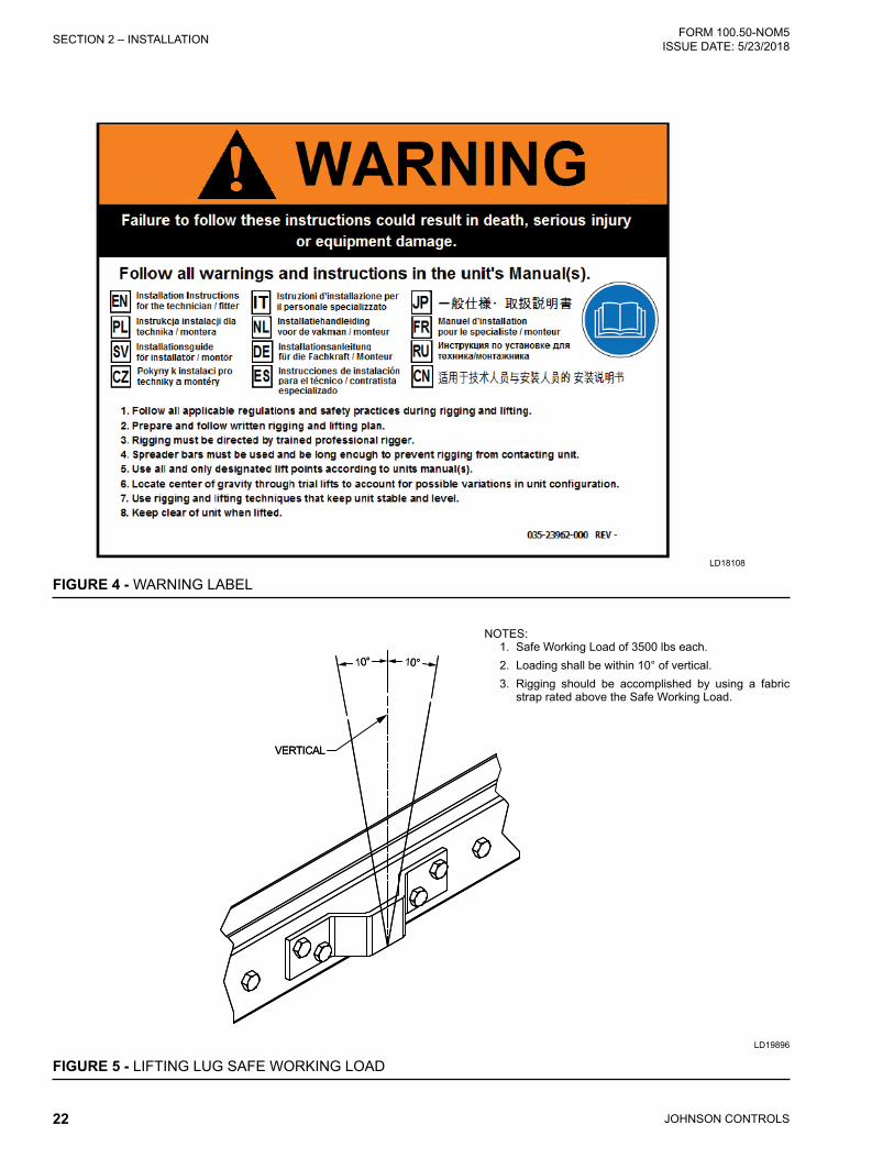
JOHNSON CONTROLS22
FORM 100.50-NOM5ISSUE DATE: 5/23/2018SECTION 2 – INSTALLATION
LD18108
FIGURE 4 - WARNING LABEL
10°
VERTICAL
10° 0°
VERTICAL
0°
FIGURE 5 - LIFTING LUG SAFE WORKING LOADLD19896
NOTES:1. Safe Working Load of 3500 lbs each.2. Loading shall be within 10° of vertical.3. Rigging should be accomplished by using a fabric
strap rated above the Safe Working Load.

JOHNSON CONTROLS 23
SECTION 2 – INSTALLATIONFORM 100.50-NOM5 ISSUE DATE: 5/23/2018
2
UNIT WEIGHTS
TABLE 3 - UNIT WEIGHTS - 050-061 MODELSWEIGHT (LBS)
MODEL 050 051 060 061BASE UNIT WEIGHT - Standard Cabinet 8650 8650 8941 8960BASE UNIT WEIGHT - Extended Cabinet 9493 9493 9784 9803Base unit is cooling only with a class 1 FC supply fan with 20 HP motor, supply fan VFD, 2" throwaway filters, aluminum coils, no condenser guards, no return or exhaust and no economizer.
COIL OPTIONSMODEL 050 051 060 061
Copper Cond Coils 520 520 760 760Copper Evap Coils 440 440 620 620
SUPPLY FAN OPTIONSSUPPLY FAN 050 051 060 061
Supply Fan FC, Class 2 41 41 41 41Supply Fan AF, Class 2 128 128 128 128
SUPPLY FAN MOTOR 050 051 060 061Supply Fan Motor - 5 HP -150 -150 -150 -150Supply Fan Motor - 7.5 HP -117 -117 -117 -117Supply Fan Motor - 10 HP -93 -93 -93 -93Supply Fan Motor - 15 HP -20 -20 -20 -20Supply Fan Motor - 25 HP 93 93 93 93Supply Fan Motor - 30 HP 135 135 135 135Supply Fan Motor - 40 HP 237 237 237 237
SUPPLY FAN VFD 050 051 060 061Supply Fan VFD - 5 - 10 HP -29 -29 -29 -29Supply Fan VFD - 30 - 40 HP 15 15 15 15
FILTER OPTIONSMODEL 050 051 060 061
2" Cleanable 0 0 0 02" Pleated 0 0 0 02" Carbon 0 0 0 0Rigid Filter - 2" Throwaway - Only 0 0 0 0Rigid Filter - 12" 60-65% 319 319 319 319Rigid Filter - 12" 90-95% 319 319 319 319Final Filters 305 305 305 305

JOHNSON CONTROLS24
FORM 100.50-NOM5ISSUE DATE: 5/23/2018SECTION 2 – INSTALLATION
WEIGHT (LBS)MODEL 050 051 060 061
ECONOMIZER / EXHAUST / RETURN FAN OPTIONSEconomizer 527 527 527 527
EXHAUST-RETURN FAN 050 051 060 061Exhaust Fan Option 465 465 465 465Return Fan Option 691 691 691 691
EXHAUST DAMPER 050 051 060 061Exhaust Damper Barometric 36 36 36 36Exhaust Damper Modulating 53 53 53 53
EXHAUST-RETURN FAN MOTOR 050 051 060 061Exhaust Fan Motor - 5hp 87 87 87 87Exhaust Fan Motor - 7.5hp 120 120 120 120Exhaust Fan Motor - 10hp 144 144 144 144Exhaust Fan Motor - 15hp 217 217 217 217Return Fan Motor - 5 HP 174 174 174 174Return Fan Motor - 7.5 HP 240 240 240 240Return Fan Motor - 10 HP 288 288 288 288Return Fan Motor - 15 HP 434 434 434 434
EXHAUST FAN VFD 050 051 060 061Exhaust Fan VFD 5 - 10 HP 22 22 22 22Exhaust Fan VFD 15 HP 51 51 51 51
CONDENSER GUARD OPTIONSMODEL 050 051 060 061
Condenser Coil Guard (Wire) 64 64 64 64Condenser Coil Guard Louvered Sheet Metal) 292 292 292 292
HEAT OPTIONSMODEL 050 051 060 061
Electric Heat - 40kW (Max) 410 410 410 410Electric Heat - 80kW (Max) 430 430 430 430Electric Heat - 108kW (Max) 450 450 450 450Electric Heat - 150kW (Max) 470 470 470 470Electric Heat - 200kW (Max) 490 490 490 490
ECONOMIZER / EXHAUST FAN / RETURN FAN OPTIONSMODEL 050 051 060 061
Electric Heat - 250kW (Max) 510 510 510 510Gas Heat - 375 MBH (Max) 162 162 162 162Gas Heat - 750 MBH (Max) 324 324 324 324Gas Heat - 1125 MBH (Max) 486 486 486 486Hot Water Coil 281 281 281 281Steam Coil 202 202 202 202
TABLE 3 - UNIT WEIGHTS - 050-061 MODELS (CONT'D)

JOHNSON CONTROLS 25
SECTION 2 – INSTALLATIONFORM 100.50-NOM5 ISSUE DATE: 5/23/2018
2
LD14760
B
A
C
D
CENTER OF GRAVITY
CONDENSERCOIL END
92Y
X339 STD
386 EXT CAB
TABLE 4 - UNIT CENTER OF GRAVITY AND CORNER LOADSSTANDARD CABINET
MODEL 50 51 60 61COORDINATE X Y X Y X Y X YBASIC UNIT 189 44 189 44 189 44 190 44BASIC UNIT W/ ECONO 181 44 181 44 181 44 182 44BASIC UNIT W/ ECONO and HEATING (Hot Water Heat) 182 44 182 44 182 44 182 44BASIC UNIT W/ ECONO and HEATING (hot Water Heat) and POWER EXHAUST (10HP motor, modulating damper, no VFD)
171 44 171 44 172 44 172 44
MODEL 50 51COORDINATE A B C D A B C DBASIC UNIT 2011 1816 2288 2534 2011 1816 2288 2534BASIC UNIT W/ ECONO 2236 2031 2318 2553 2236 2031 2318 2553BASIC UNIT W/ ECONO and HEATING (Hot Water Heat) 2281 2092 2413 2632 2281 2092 2413 2632BASIC UNIT W/ ECONO and HEATING (hot Water Heat) and POWER EXHAUST (10HP motor, modulating damper, no VFD)
2607 2390 2431 2652 2607 2390 2431 2652
MODEL 60 61COORDINATE A B C D A B C DBASIC UNIT 2077 1868 2366 2630 2076 1873 2376 2634BASIC UNIT W/ ECONO 2302 2082 2395 2649 2301 2087 2406 2653BASIC UNIT W/ ECONO and HEATING (Hot Water Heat) 2347 2143 2491 2728 2346 2148 2502 2732BASIC UNIT W/ ECONO and HEATING (hot Water Heat) and POWER EXHAUST (10HP motor, modulating damper, no VFD)
2673 2441 2509 2748 2672 2446 2519 2752

JOHNSON CONTROLS26
FORM 100.50-NOM5ISSUE DATE: 5/23/2018SECTION 2 – INSTALLATION
LD14760
B
A
C
D
CENTER OF GRAVITY
CONDENSERCOIL END
92Y
X339 STD
386 EXT CAB
EXTENDED CABINETMODEL 50 51 60 61
COORDINATE X Y X Y X Y X YBASIC UNIT 212 44 212 44 212 44 213 44BASIC UNIT W/ ECONO 203 44 203 44 204 44 204 44BASIC UNIT W/ ECONO and HEATING (Hot Water Heat) 204 44 204 44 204 44 205 44BASIC UNIT W/ ECONO and HEATING (hot Water Heat) and POWER EXHAUST (10HP motor, modulating damper, no VFD)
192 44 192 44 193 44 194 44
MODEL 50 51COORDINATE A B C D A B C DBASIC UNIT 2241 2041 2483 2727 2241 2041 2483 2727BASIC UNIT W/ ECONO 2469 2258 2510 2744 2469 2258 2510 2744BASIC UNIT W/ ECONO and HEATING (Hot Water Heat) 2522 2327 2598 2815 2522 2327 2598 2815BASIC UNIT W/ ECONO and HEATING (hot Water Heat) and POWER EXHAUST (10HP motor, modulating damper, no VFD)
2850 2628 2612 2833 2850 2628 2612 2833
MODEL 60 61COORDINATE A B C D A B C DBASIC UNIT 2307 2092 2561 2824 2306 2097 2572 2828BASIC UNIT W/ ECONO 2535 2310 2587 2839 2534 2315 2598 2844BASIC UNIT W/ ECONO and HEATING (Hot Water Heat) 2588 2378 2675 2911 2587 2383 2686 2915BASIC UNIT W/ ECONO and HEATING (hot Water Heat) and POWER EXHAUST (10HP motor, modulating damper, no VFD)
2916 2679 2690 2929 2915 2684 2701 2933
TABLE 4 - UNIT CENTER OF GRAVITY AND CORNER LOADS (CONT'D)

JOHNSON CONTROLS 27
SECTION 2 – INSTALLATIONFORM 100.50-NOM5 ISSUE DATE: 5/23/2018
2
TABLE 5 - UNIT CORNER WEIGHTS - 050-061 MODELSSTANDARD CABINET
50 51A B C D A B C D
BASIC UNIT 2011 1816 2288 2534 2011 1816 2288 2534BASIC UNIT W/ ECONO 2236 2031 2318 2553 2236 2031 2318 2553BASIC UNIT W/ ECONO and HEATING (Hot Water Heat) 2281 2092 2413 2632 2281 2092 2413 2632BASIC UNIT W/ ECONO and HEATING (hot Water Heat) and POWER EXHAUST (10HP motor, modulating damper, no VFD)
2607 2390 2431 2652 2607 2390 2431 2652
60 61A B C D A B C D
BASIC UNIT 2077 1868 2366 2630 2076 1873 2376 2634BASIC UNIT W/ ECONO 2302 2082 2395 2649 2301 2087 2406 2653BASIC UNIT W/ ECONO and HEATING (Hot Water Heat) 2347 2143 2491 2728 2346 2148 2502 2732BASIC UNIT W/ ECONO and HEATING (hot Water Heat) and POWER EXHAUST (10HP motor, modulating damper, no VFD)
2673 2441 2509 2748 2672 2446 2519 2752
EXTENDED CABINET50 51
A B C D A B C DBASIC UNIT 2241 2041 2483 2727 2241 2041 2483 2727BASIC UNIT W/ ECONO 2469 2258 2510 2744 2469 2258 2510 2744BASIC UNIT W/ ECONO and HEATING (Hot Water Heat) 2522 2327 2598 2815 2522 2327 2598 2815BASIC UNIT W/ ECONO and HEATING (hot Water Heat) and POWER EXHAUST (10HP motor, modulating damper, no VFD)
2850 2628 2612 2833 2850 2628 2612 2833
60 61A B C D A B C D
BASIC UNIT 2307 2092 2561 2824 2306 2097 2572 2828BASIC UNIT W/ ECONO 2535 2310 2587 2839 2534 2315 2598 2844BASIC UNIT W/ ECONO and HEATING (Hot Water Heat) 2588 2378 2675 2911 2587 2383 2686 2915BASIC UNIT W/ ECONO and HEATING (hot Water Heat) and POWER EXHAUST (10HP motor, modulating damper, no VFD)
2916 2679 2690 2929 2915 2684 2701 2933

JOHNSON CONTROLS28
FORM 100.50-NOM5ISSUE DATE: 5/23/2018SECTION 2 – INSTALLATION
Unit Placement
Elevated Elevated roof curbs or dunnage steel can be used to support the unit in order to raise it to specific heights. When this type of placement is required, be sure to keep unit access in mind. Cat walks or other forms of unit access may be required to one or both sides of the unit, depending on your area of the country and the local codes that are enforced. Please check with local officials to ensure the application conforms to local codes and regulations.
Ground Level LocationsIt is important that the units be installed on a substan-tial base that will not settle, causing strain on the re-frigerant lines and sheet metal and resulting in possible leaks. A one piece concrete slab with footers extended below the frost line is highly recommended. Addition-ally, the slab should be isolated from the main building foundation to prevent noise and vibration transmission to the building structure.
For ground level installations, precautions should be taken to protect the unit from tampering by, or injury to, unauthorized persons. Erecting a fence around the unit is common practice.
ROOF CURB INSTALLATIONJohnson Controls offers an optional roof curb designed specifically for the Series 100 foot print. This curb comes as an open condenser model and is shipped dis-assembled and requires field assembly during installa-tion. Refer to the Installation Manual that is shipped with the roof curb for specific instructions. For bottom supply and return openings, the curb has matching con-nections to ease installation.
The curb should be located according to the location recommendations above, and properly sealed to pre-vent moisture and air leakage into and out of the duct system. Flexible collars should be used when connect-ing the duct work to prevent unit noise transmission and vibration into the building. The roof curb draw-ings contained in the Johnson Controls literature are not intended as construction documents for field fab-rication of a roof curb. Johnson Controls will not be responsible for the unit fit up, leak integrity, or sound level with field fabricated roof curbs.
Construction documents for field fabricated roof curbs are available upon request.
Wood or fiber cant strips, roofing felts, roofing material, caulking and curb-to-roof fasteners are to be field supplied.

JOHNSON CONTROLS 29
SECTION 2 – INSTALLATIONFORM 100.50-NOM5 ISSUE DATE: 5/23/2018
2
PHYSICAL DATA
TABLE 6 - PHYSICAL DATA – 050-061 MODELSUNIT SIZE 050 051 060 061
GENERAL DATALength without hood (inches) 339/386 339/386 339/386 339/386Width (inches) 92 92 92 92Height (inches) 82 82 82 82Unit EER/ IPLV 10.3 / 10.9 10.2 / 10.6 10.1 / 10.4 10.1 / 10.3Unit EER/ IPV gas heat 10.01 9.91 9.81 9.81
COMPRESSOR DATA (SEE TABLE 7)Quantity 4 4 4 4Type Scroll Scroll Scroll ScrollUnit Capacity Steps 4 4 4 4
REFRIGERANT (410A) - EXTENDED CABINETSYSTEM 1 49 lbs - 8 oz 49 lbs - 8 oz 58 lbs - 11 oz 58 lbs - 11 ozSYSTEM 2 49 lbs - 8 oz 49 lbs - 8 oz 58 lbs - 11 oz 58 lbs - 11 ozs
SUPPLY FANQuantity 1 1 1 1Type FC FC FC FCSize 28 - 28 28 - 28 28 - 28 28 - 28Motor Size Range (HP) 10 - 25 10 - 25 10 - 25 10 - 25Air Flow Range (CFM) cooling Min.
10,000 - 22,500 10,000 - 22,500 12,500 - 24,000 10,000 - 24,000
Static Pressure Range (total) 1.0” - 6.0” 1.0” - 6.0” 1.0” - 6.0” 1.0” - 6.0”OPTIONAL SUPPLY FAN
Quantity 1 1 1 1Type AF AF AF AFSize 28 28 28 28Motor Size Range (HP) 10 - 40 10 - 40 10 - 40 10 - 40Air Flow Range (CFM) cooling Min.
10,000 - 22,500 10,000 - 22,500 10,000 - 24,000 10,000 - 24,000
Static Pressure Range (total) 1.0” - 8.0” 1.0” - 8.0” 1.0” - 8.0” 1.0” - 8.0”EXHAUST FAN
Quantity Fans/Motors 2 / 1 2 / 1 2 / 1 2 / 1Type FC FC FC FCSize 18 - 18 18 - 18 18 - 18 18 - 18Motor Size Range (HP) 5 - 15 5 - 15 5 - 15 5 - 15Air Flow Range (CFM) 4,000 - 22,500 4,000 - 22,500 4,000 - 24,000 4,000 - 24,000Static Pressure Range (total) 0.1” - 1.5” 0.1” - 1.5” 0.1” - 1.5” 0.1” - 1.5”
EVAPORATOR COILSize (square feet) 52 52 52 52Rows/FPI 3 / 17 3 / 17 4 / 17 4 / 17
CONDENSER COILSize (square feet) 88 88 88 88Rows/FPI 2 / 17 2 / 17 3 / 17 3 / 17
CONDENSER FANSQuantity 4 4 4 4Type Prop. Prop. Prop. Prop.Diameter (inches) 36 36 36 36Motor HP 2 2 2 2

JOHNSON CONTROLS30
FORM 100.50-NOM5ISSUE DATE: 5/23/2018SECTION 2 – INSTALLATION
UNIT SIZE 050 051 060 061FILTERS - 2” THROWAWAY (PRE-FILTER POSITION), MERV 4
Quantity 4 / 12 4 / 12 4 / 12 4 / 12Size (length x width) (in.) 12X24 / 24X24 12X24 / 24X24 12X24 / 24X24 12X24 / 24X24Total Filter Face Area (square feet)
56 61.6 61.6 61.6
FILTERS - 2” CLEANABLE (PRE-FILTER POSITION), MERV 1Quantity 4 / 12 4 / 12 4 / 12 4 / 12Size (length x width) (in.) 12X24 / 24X24 12X24 / 24X24 12X24 / 24X24 12X24 / 24X24Total Filter Face Area (square feet)
56 63.9 63.9 63.9
FILTERS - 2” PLEATED, 30% EFFICIENT (PRE-FILTER POSITION), MERV 8Quantity 4 / 12 4 / 12 4 / 12 4 / 12Size (length x width) (in.) 12X24 / 24X24 12X24 / 24X24 12X24 / 24X24 12X24 / 24X24Total Filter Face Area (square feet)
56 63.9 63.9 63.9
FILTERS -12” RIGID 65%, 2” 30% PREFILTER (PRE-FILTER POSITION), MERV 11 AND 8Quantity 1 / 4 / 9 1 / 4 / 9 1 / 4 / 9 1 / 4 / 9Size (length x width) (in.) 16x20/25x16/25x20 16x20/25x16/25x20 16x20/25x16/25x20 16x20/25x16/25x20Total Filter Face Area (square feet)
43.0 43.0 43.0 43.0
FILTERS -12” RIGID 95%, 2” 30% PREFILTER (PRE-FILTER POSITION), MERV 14 AND 8Quantity 1 / 4 / 9 1 / 4 / 9 1 / 4 / 9 1 / 4 / 9Size (length x width) (in.) 16x20/25x16/25x20 16x20/25x16/25x20 16x20/25x16/25x20 16x20/25x16/25x20Total Filter Face Area (square feet)
44.6 44.6 44.6 44.6
FILTERS - 2” CARBON (PRE-FILTER POSITION), MERV 8Quantity 4 / 12 4 / 12 4 / 12 4 / 12Size (length x width) (in.) 12X24 / 24X24 12X24 / 24X24 12X24 / 24X24 12X24 / 24X24Total Filter Face Area (square feet)
56 63.9 63.9 63.9
FILTERS - 12” RIGID 95% IN POST-FILTER POSITION, MERV 14Quantity 3 / 9 3 / 9 3 / 9 3 / 9Size (length x width) (in.) 16x20/25x16/25x20 16x20/25x16/25x20 16x20/25x16/25x20 16x20/25x16/25x20Total Filter Face Area (square feet)
39.6 39.6 39.6 39.6
TABLE 6 - PHYSICAL DATA – 050-061 MODELS (CONT'D)

JOHNSON CONTROLS 31
SECTION 2 – INSTALLATIONFORM 100.50-NOM5 ISSUE DATE: 5/23/2018
2
UNIT SIZE 050 051 060 061GAS FURNACES
Staged Furnace Sizes (input/output/steps)375 mbh / 300 mbh / 2 steps750 mbh / 600 mbh / 4 steps1125 mbh / 900 mbh / 6 steps
Inlet Gas Pressure Range Natural 4.5–10.5 "W.C. 4.5–10.5 "W.C. 4.5–10.5 "W.C. 4.5–10.5 "W.C.Propane 11.0–13.0 "W.C. 11.0–13.0 "W.C. 11.0–13.0 "W.C. 11.0–13.0 "W.C.
Airflow Range(MIN HEATING)
375 MBH 7,500 7,500 11,500 11,500750 MBH 14,000 14,000 14,000 14,0001125 MBH 21,000 21,000 21,000 21,000
Modulating Furnace Sizes (Input/Output/Turndown)375 mbh / 300 mbh / 8:1 TURNDOWN
750 mbh / 600 mbh / 16:1 TURNDOWN1125 mbh / 900 mbh / 24:1 TURNDOWN
Inlet Gas Pressure Range Natural 4.5–10.5 "W.C. 4.5–10.5 "W.C. 4.5–10.5 "W.C. 4.5–10.5 "W.C.Propane 11.0–13.0 "W.C. 11.0–13.0 "W.C. 11.0–13.0 "W.C. 11.0–13.0 "W.C.
Airflow Range(MIN HEATING)
375 MBH 7,500 7,500 11,500 11,500750 MBH 14,000 14,000 14,000 14,0001125 MBH 21,000 21,000 21,000 21,000
Minimum OA Temp for Mech. Cig. 40.0 °F 40.0 °F 40.0 °F 40.0 °FLow Ambient Option Min. OA Temp 0.0 °F 0.0 °F 0.0 °F 0.0 °F
TABLE 7 - PHYSICAL DATA - COMPRESSORSCOMPRESSORS UTILIZED COMPRESSOR NOMINAL HP
CAPACITY %SYSTEM 1 SYSTEM 2 SYSTEM 1 SYSTEM 21A 1B 2A 2B 1A 1B 2A 2B 1A 1B 2A 2B
MODEL
50 ZP120 ZP137 ZP120 ZP137 10 12 10 12 24 48 74 10051 ZP137 ZP137 ZP137 ZP137 12 12 12 12 25 50 75 10060 ZP137 ZP182 ZP137 ZP182 12 15 12 15 21.5 43.1 72.1 10061 ZP137 ZP182 ZP154 ZP182 12 15 13 15 12.1 44.2 72.1 100
TABLE 6 - PHYSICAL DATA – 050-061 MODELS (CONT'D)

JOHNSON CONTROLS32
FORM 100.50-NOM5ISSUE DATE: 5/23/2018SECTION 2 – INSTALLATION
LD08295B
FIGURE 6 - LOCATION AND DIMENSION DRAWING / 050-061 MODELS, BOTTOM SUPPLY / BOTTOM RETURN, STANDARD CABINET
SEC
TIO
N D
ESC
RIP
TIO
NS:
EE
= E
cono
miz
erFE
= F
an E
xhau
st_F
= F
ilter
Seg
men
tsC
C =
Coo
ling
Coi
lsFS
= S
uppl
y Fa
nD
P =
Dis
char
ge P
lenu
mC
O =
Con
dens
er S
ectio
n
NO
TES:
1. 1
0’ c
lear
ance
min
imal
ove
r the
top
of th
e co
nden
sing
uni
t.2.
Onl
y on
e ad
jace
nt w
all c
an e
xcee
d un
it he
ight
.3.
12’
cle
aran
ce re
quire
d to
adj
acen
t uni
ts.
4. 8
’ ser
vice
acc
ess
reco
mm
ende
d on
one
sid
e.5.
Eco
nom
izer
and
exh
aust
hoo
ds, w
here
app
licab
le a
re fo
lded
insi
de u
nit f
or s
hipm
ent.
82.0
0
30.0
0 D
OO
RS
WIN
G
CLE
AR
AN
CE
BO
TH S
IDE
S
78.0
0 C
LEA
RFO
R C
OIL
PU
LL
92.0
010
0.50
RE
AR
VIE
W
46.0
060
.00
1-1/
4" F
PT
DR
AIN
SB
OTH
SID
ES
39.0
0
AIR
FLO
W
1.50
91.0
0C
LEA
RFO
R C
OIL
PU
LL
120.
00 C
LEA
R
84.0
0C
LEA
R
CO
DP
FSC
C
_FE
E
FE
339.
00
170.
31
ELE
CTR
ICA
L S
ER
VIC
E
86.5
0
67.2
5
5.50 4.56
OAOA
191.
1923
0.62
5.74
75.5
869
.83
TOP
VIE
W
136.
8260
.00
CLE
AR
FOR
AIR
IN
TAK
EB
OTH
S
IDE
S
FRO
NT
VIE
WS
IDE
VIE
W(L
EFT
SID
E)

JOHNSON CONTROLS 33
SECTION 2 – INSTALLATIONFORM 100.50-NOM5 ISSUE DATE: 5/23/2018
2
FIGURE 7 - LOCATION AND DIMENSION DRAWING / 050-061 MODELS, BOTTOM SUPPLY / SIDE RETURN, STANDARD CABINET
SEC
TIO
N D
ESC
RIP
TIO
NS:
EE
= E
cono
miz
erFE
= F
an E
xhau
st_F
= F
ilter
Seg
men
tsC
C =
Coo
ling
Coi
lsFS
= S
uppl
y Fa
nD
P =
Dis
char
ge P
lenu
mC
O =
Con
dens
er S
ectio
n
LD08370A
NO
TES:
1. 1
0’ c
lear
ance
min
imal
ove
r the
top
of th
e co
nden
sing
uni
t.2.
Onl
y on
e ad
jace
nt w
all c
an e
xcee
d un
it he
ight
.3.
12’
cle
aran
ce re
quire
d to
adj
acen
t uni
ts.
4. 8
’ ser
vice
acc
ess
reco
mm
ende
d on
one
sid
e.5.
Eco
nom
izer
and
exh
aust
hoo
ds, w
here
app
licab
le a
re fo
lded
insi
de u
nit f
or s
hipm
ent.
6.28
38.3
7
49.9
44.
79
GA
SB
UR
NE
RS
GA
SH
EA
TE
XHA
US
TFL
UE
FIE
LDIN
STA
LLE
D
102.
62S
IDE
VIE
W(L
EFT
SID
E)
FRO
NT
VIE
W
1.50
78.0
0C
LEA
RFO
RC
OIL
PU
LL
30.0
0D
OO
RS
WIN
GC
LEA
R-
AN
CE
BO
THS
IDE
S
95.2
592
.00
82.0
0
84.0
0C
LEA
R91
.00
CLE
AR
FOR
CO
ILP
ULL
120.
00C
LEA
R
AIR
FLO
W
106.
00
1-1/
4"FP
TD
RA
INLE
FTS
IDE
ON
LY
GA
SLI
NE
CO
NN
EC
TIO
N2-
1/2"
GA
SO
UTL
ET
1-1/
2"M
PT
CO
NN
.
195.
3822
1.00
GA
SH
EA
TFL
UE
TOP
VIE
W
339.
00
170.
31
ELE
CTR
ICA
LS
ER
VIC
E
OAOA
69.8
375
.58
5.74
230.
62
191.
19
RE
AR
VIE
W
60.0
0C
LEA
RFO
RA
IRIN
BO
THS
IDE
S
136.
82

JOHNSON CONTROLS34
FORM 100.50-NOM5ISSUE DATE: 5/23/2018SECTION 2 – INSTALLATION
FIGURE 8 - LOCATION AND DIMENSION DRAWING / 050-061 MODELS, SIDE SUPPLY / REAR RETURN, STANDARD CABINET
LD08296A
NO
TES:
1. 1
0’ c
lear
ance
min
imal
ove
r the
top
of th
e co
nden
sing
uni
t.2.
Onl
y on
e ad
jace
nt w
all c
an e
xcee
d un
it he
ight
.3.
12’
cle
aran
ce re
quire
d to
adj
acen
t uni
ts.
4. 8
’ ser
vice
acc
ess
reco
mm
ende
d on
one
sid
e.5.
Eco
nom
izer
and
exh
aust
hoo
ds, w
here
app
licab
le a
re fo
lded
insi
de u
nit f
or s
hipm
ent.
SEC
TIO
N D
ESC
RIP
TIO
NS:
EE
= E
cono
miz
erFE
= F
an E
xhau
st_F
= F
ilter
Seg
men
tsC
C =
Coo
ling
Coi
lsFS
= S
uppl
y Fa
nD
P =
Dis
char
ge P
lenu
mC
O =
Con
dens
er S
ectio
n
82.0
0
30.0
0 D
OO
RS
WIN
GC
LEA
RA
NC
EB
OTH
SID
ES
78.0
0 C
LEA
RFO
R C
OIL
PU
LL
92.0
0
100.
50
FRO
NT
VIE
W
AIR
FLO
W
339.
00
170.
31
ELE
CTR
ICA
L S
ER
VIC
E
OAOA
TOP
VIE
W
66.0
0
227.
25195.
00
11.0
0
46.0
060
.00
1-1/
4" F
PT
DR
AIN
SB
OTH
SID
ES
39.0
010
6.00
1.50
91.0
0C
LEA
RFO
R C
OIL
PU
LL
120.
00 C
LEA
R
84.0
0C
LEA
R
CO
DP
FSC
C_F
EE
FE
SID
E V
IEW
(LE
FT S
IDE
)
76.4
87.
76
6.36
36.2
8
136.
82
60.0
0 C
LEA
RFO
R A
IR IN
TAK
EB
OTH
SID
ES
RE
AR
VIE
W

JOHNSON CONTROLS 35
SECTION 2 – INSTALLATIONFORM 100.50-NOM5 ISSUE DATE: 5/23/2018
2
LD14761FIGURE 9 - LOCATION AND DIMENSION DRAWING, / 050-061 MODELS, BOTTOM SUPPLY / BOTTOM
RETURN, EXTENDED CABINET
NO
TES:
1. 1
0’ c
lear
ance
min
imal
ove
r the
top
of th
e co
nden
sing
uni
t.2.
Onl
y on
e ad
jace
nt w
all c
an e
xcee
d un
it he
ight
.3.
12’
cle
aran
ce re
quire
d to
adj
acen
t uni
ts.
4. 8
’ ser
vice
acc
ess
reco
mm
ende
d on
one
sid
e.5.
Eco
nom
izer
and
exh
aust
hoo
ds, w
here
app
licab
le a
re fo
lded
insi
de u
nit f
or s
hipm
ent.
AIR
FLO
W
60.0
0 C
LEA
RFO
R A
IR IN
TAK
E
BO
TH S
IDE
S13
6.82
10
6.00
1.50
1-1/
4" F
PT
DR
AIN
LEFT
SID
E O
NLY
136.
82C
LEA
R
120.
00 C
LEA
R
91.0
0 C
LEA
R F
OR
C
OIL
PU
LL
95.2
592
.00
82.0
0
30.0
0 D
OO
RS
WIN
G C
LEA
RA
NC
EB
OTH
SID
ES
78.0
0 C
LEA
RFO
R C
OIL
PU
LL
385.
81
170.
31
86.2
6
5.7480
.51
ELE
CTR
ICA
L S
ER
VIC
E
4.56
136.
82
246.
8127
7.56
67.2
5
5.50
86.5
0
TOP
VIE
W
RE
AR
VIE
WFR
ON
T V
IEW
SID
E V
IEW

JOHNSON CONTROLS36
FORM 100.50-NOM5ISSUE DATE: 5/23/2018SECTION 2 – INSTALLATION
LD14762
NO
TES:
1. 1
0’ c
lear
ance
min
imal
ove
r the
top
of th
e co
nden
sing
uni
t.2.
Onl
y on
e ad
jace
nt w
all c
an e
xcee
d un
it he
ight
.3.
12’
cle
aran
ce re
quire
d to
adj
acen
t uni
ts.
4. 8
’ ser
vice
acc
ess
reco
mm
ende
d on
one
sid
e.5.
Eco
nom
izer
and
exh
aust
hoo
ds, w
here
app
licab
le a
re fo
lded
insi
de u
nit f
or s
hipm
ent.
FIGURE 10 - LOCATION AND DIMENSION DRAWING / 050-061 MODELS, BOTTOM SUPPLY / SIDE RETURN, EXTENDED CABINET
170.
31
AIR
FLO
W
60.0
0 C
LEA
RFO
R A
IR IN
TAK
E
BO
TH S
IDE
S13
6.82
10
6.00
38.3
7
6.28
4.79
49.9
4
210.
40
1.50
11.2
51-
1/4"
FP
T D
RA
INLE
FT S
IDE
ON
LY
84.0
0C
LEA
R
385.
81
ELE
CTR
ICA
L S
ER
VIC
E4.
22
246.
8127
7.56
5.74
63.25
2-1/
8" O
D
CO
PP
ER
C
ON
NE
CTI
ON
TY
P
120.
00 C
LEA
R
91.0
0 C
LEA
RFO
R C
OIL
PU
LL
30.0
0 D
OO
RS
WIN
G C
LEA
RA
NC
EB
OTH
SID
ES
78.0
0 C
LEA
RFO
R C
OIL
PU
LL
92.0
095
.25
82.0
0
80.5
186
.26
TOP
VIE
W
RE
AR
VIE
WFR
ON
T V
IEW
SID
E V
IEW

JOHNSON CONTROLS 37
SECTION 2 – INSTALLATIONFORM 100.50-NOM5 ISSUE DATE: 5/23/2018
2
LD14763
NO
TES:
1. 1
0’ c
lear
ance
min
imal
ove
r the
top
of th
e co
nden
sing
uni
t.2.
Onl
y on
e ad
jace
nt w
all c
an e
xcee
d un
it he
ight
.3.
12’
cle
aran
ce re
quire
d to
adj
acen
t uni
ts.
4. 8
’ ser
vice
acc
ess
reco
mm
ende
d on
one
sid
e.5.
Eco
nom
izer
and
exh
aust
hoo
ds, w
here
app
licab
le a
re fo
lded
insi
de u
nit f
or s
hipm
ent.
FIGURE 11 - LOCATION AND DIMENSION DRAWING / 050-061 MODELS, SIDE SUPPLY / REAR RETURN, EXTENDED CABINET
170.
31
AIR
FLO
W
60.0
0 C
LEA
RFO
R A
IR IN
TAK
E
BO
TH S
IDE
S13
6.82
76.4
87.
76
36.2
8
6.36
106.
00
1.50
277.
30
247.
72
1-1/
4" F
PT
DR
AIN
LEFT
SID
E O
NLY
84.0
0C
LEA
R
385.
81
ELE
CTR
ICA
L S
ER
VIC
E
72.2
1
6.40
120.
00 C
LEA
R
91.0
0 C
LEA
RFO
R C
OIL
PU
LL
30.0
0 D
OO
RS
WIN
G C
LEA
RA
NC
EB
OTH
SID
ES
78.0
0 C
LEA
RFO
R C
OIL
PU
LL
92.0
095
.25
82.0
0
TOP
VIE
W
RE
AR
VIE
WFR
ON
T V
IEW
SID
E V
IEW

JOHNSON CONTROLS38
FORM 100.50-NOM5ISSUE DATE: 5/23/2018SECTION 2 – INSTALLATION
229.56
66.08
333.69
41.19
71.83
66.1921.0035.10
14.00
84.50
1.75TYP
SUPPLY
RETURN
LD08297
LD14765
FIGURE 12 - CURB LAYOUT DRAWING / 050-061 MODELS, STANDARD AND EXTENDED CABINET
NOTES:1. Unit must be installed square and level.2. Curb configuration for “bottom” return and “bottom” supply.3, These drawings are not intended as construction documents for the field fabricated roof curbs. Johnson Controls will not be responsible for
the unit fit up, leak integrity, or sound level for installation using field fabricated roof curbs.4. The Series 100 unit does not have a base pan under the condensing section of the unit. Field fabricated roof curbs must have a cap on the
top of the condensing section of the curb to prevent moisture from entering the space. The cap design must be sloped away from the supply duct opening to the end of the unit for the drainage of the moisture off of the top of the cap.
STANDARD CABINET
EXTENDED CABINET
333.69
41.19 66.08 35.10 21.00 66.19
84.50
1.75TYP
14.00
229.56
RE
TUR
NR
ETU
RN
SU
PP
LY
SU
PP
LY
71.83
84.50
32.5015.38
40.12 66.21 35.10 21.00 66.19
380.50
84.5081.00
1.75TYP276.50
14.00

JOHNSON CONTROLS 39
SECTION 2 – INSTALLATIONFORM 100.50-NOM5 ISSUE DATE: 5/23/2018
2
ELECTRICAL DATA
Electrical Service SizingIn order to use the electrical service required for the cooling-only Packaged Rooftop Unit, use the appropri-ate calculations listed below from U.L. 1995. Based on the configuration of the rooftop, the calculations will yield different MCA (minimum circuit ampacity), and MOP (maximum overcurrent protection).
Using the following load definitions and calculations, determine the correct electrical sizing for your unit. All concurrent load conditions must be considered in the calculations, and you must use the highest value for any combination of loads.
Load Definitions• LOAD1 is the current of the largest motor – com-
pressor or fan motor.
• LOAD2 is the sum of the remaining motor cur-rents that may run concurrently with LOAD1.
• LOAD3 is the current of the electric heaters – zero for cooling-only units.
• LOAD4 is the sum of any remaining currents greater than or equal to 1.0 amp.
Use the following calculations to determine MCA and MOP for units supplied with a single-point power con-nection:
MCA = (1.25 x LOAD1) + LOAD2 + LOAD3 + LOAD4
MOP = (2.25 x LOAD1) + LOAD2 + LOAD3 + LOAD4
If the MOP does not equal a standard current rating of an overcurrent protective device, then the marked maximum rating is to be the next lower standard rating. However, if the device selected for MOP is less than the MCA, then select the lowest standard maximum fuse size greater than or equal to the MCA.
TABLE 8 - COMPRESSOR DATA - R-410A
MODEL COMPRESSOR MODELNOMINAL VOLTAGE
208-230/3/60 460/3/60 575/3/60RLA* LRA RLA* LRA RLA* LRA
050
1A ZP120 33.3 239 17.9 125 12.8 801B ZP137 48.0 245 18.6 125 14.7 1002A ZP120 33.3 239 17.9 125 12.8 802B ZP137 48.0 245 18.6 125 14.7 100
051
1A ZP137 48.0 245 18.6 125 14.7 1001B ZP137 48.0 245 18.6 125 14.7 1002A ZP137 48.0 245 18.6 125 14.7 1002B ZP137 48.0 245 18.6 125 14.7 100
060
1A ZP137 48.0 245 18.6 125 14.7 1001B ZP182 55.7 340 26.9 172 23.7 1322A ZP137 48.0 245 18.6 125 14.7 1002B ZP182 55.7 340 26.9 172 23.7 132
061
1A ZP137 48.0 245 18.6 125 14.7 1001B ZP182 55.7 340 25.0 172 23.7 1322A ZP154 51.3 300 22.4 150 19.8 1092B ZP182 55.7 340 25.0 172 23.7 132
TABLE 9 - POWER SUPPLY VOLTAGE LIMITSPOWER SUPPLY MINIMUM VOLTAGE MAXIMUM VOLTAGE
208/230V/3PH/60HZ 187 253460V/3PH/60HZ 414 506575V/3PH/60HZ 518 632

JOHNSON CONTROLS40
FORM 100.50-NOM5ISSUE DATE: 5/23/2018SECTION 2 – INSTALLATION
TABLE 10 - CONDENSER FAN MOTOR RLA - STANDARD FAN
RLA EACH MOTOR208V/3PH/60HZ 230V/3PH/60HZ 460V/3PH/60HZ 575V/3PH/60HZ
7.3 6.2 3.1 2.5
MODEL QUANTITY OF FANS 208V/3PH/60HZ 230V/3PH/60HZ 460V/3PH/60HZ 575V/3PH/60HZ
50-60 Tons 4 29.2 24.8 12.4 10.0
TABLE 11 - CONDENSER FAN MOTOR RLA - LOW SOUND FAN (FUTURE OPTION)
RLA EACH MOTOR208V/3PH/60HZ 230V/3PH/60HZ 460V/3PH/60HZ 575V/3PH/60HZ
7.3 6.2 3.1 2.5
MODEL QUANTITY OF FANS 208V/3PH/60HZ 230V/3PH/60HZ 460V/3PH/60HZ 575V/3PH/60HZ
50-60 Tons 4 32.4 27.6 13.6 12.0
TABLE 12 - SUPPLY AND EXHAUST FAN MOTOR DATA - ODPHIGH EFFICIENCY PREMIUM EFFICIENCY
MOTOR HP
NOMINAL VOLTAGEMOTOR
HP
NOMINAL VOLTAGE208/3/60 230/3/60 380/3/60 460/3/60 575/3/60 208/3/60 230/3/60 460/3/60 575/3/60
FLA FLA FLA FLA FLA FLA FLA FLA FLA5 14.0 13.8 8.3 6.9 5.3 5 13.8 13.2 6.6 5.2
7.5 21.7 20.0 13.3 10.0 8.2 7.5 20.0 19.4 9.7 7.410 28.2 26.0 17.5 13.0 11.0 10 26.0 25.0 12.5 10.315 41.0 38.0 24.5 19.0 16.2 15 37.4 35.4 17.7 14.120 53.0 48.0 32.0 24.0 19.8 20 49.4 47.0 23.5 18.925 66.0 62.0 39.0 31.0 23.8 25 63.3 60.0 30.0 24.230 84.0 72.0 46.0 36.0 29.0 30 74.1 70.0 35.0 28.040 106.0 98.0 59.0 49.0 38.8 40 97.5 92.0 46.0 37.4
TABLE 13 - SUPPLY AND EXHAUST FAN MOTOR DATA - TEFCHIGH EFFICIENCY PREMIUM EFFICIENCY
MOTOR HP
NOMINAL VOLTAGEMOTOR
HP
NOMINAL VOLTAGE208/3/60 230/3/60 380/3/60 460/3/60 575/3/60 208/3/60 230/3/60 460/3/60 575/3/60
FLA FLA FLA FLA FLA FLA FLA FLA FLA5 15.4 14.2 8.1 7.1 5.4 5 13.6 13.0 6.5 5.2
7.5 21.2 19.6 12.0 9.8 8.2 7.5 21.0 18.8 9.4 8.010 27.5 25.6 16.8 12.8 11.4 10 26.0 25.0 12.5 10.015 40.0 37.0 23.8 18.5 15.3 15 38.9 37.0 18.5 14.820 54.0 50.0 30.0 25.0 19.1 20 51.0 48.0 24.0 19.025 64.0 60.0 39.0 30.0 25.0 25 63.3 60.0 30.0 23.930 78.0 72.0 46.0 36.0 29.6 30 77.0 72.0 36.0 29.040 101.0 94.0 57.0 47.0 38.0 40 99.0 92.0 46.0 36.8
TABLE 14 - MISCELLANEOUS ELECTRICAL DATA
DESCRIPTIONNOMINAL VOLTAGE
208 / 230V 460V 575V 380V-60AMPS AMPS AMPS AMPS
CONTRL TRANSFORMER 500 VA
2.4 1.1 0.9 2
CONVENIENCE OUTLET 9.6 4.4 3.5 N/AGAS HEAT 9.6 4.4 3.5 5.3

JOHNSON CONTROLS 41
SECTION 2 – INSTALLATIONFORM 100.50-NOM5 ISSUE DATE: 5/23/2018
2
FILTERSTwo-inch “throwaway” filters are standard and factory installed in a filter rack located prior to the evaporator coil. Any optional pre-filters ordered with the unit will be shipped inside the unit, but must be field installed. The unit can also be ordered with an extended cabinet and 95% efficient post-filters. These post-filters are installed at the factory.
Pre-filters must always be installed ahead of the evap-orator coil. Post and pre-filters must be kept clean and replaced with the same size and type as shipped with the unit. Dirty filters will reduce the capacity of the unit and may result in frosted coils and safety shut-downs. Required filter sizes and quantities are shown in Table 6 on page 29. The unit should never be op-erated for any length of time without the proper filters installed in the unit. FIGURE 13 - DRAIN TRAP SHOWING WATER
LOCATION DURING DRAW THROUGH OPERATION STAGES
BASE RAILS
BASE RAILS
BASE RAILS
DRAIN NIPPLE
TRAP
NO.1 - FAN OFF
NO. 2 - TRAP CONDITION WHEN FAN STARTS
NO. 3 - FAN RUNNING AND CONDENSATE
COOLING COIL DRAIN PAN
LD13269
TABLE 15 - ELECTRIC HEAT
KWNOMINAL VOLTAGE
208/3/60AMPS
230/3/60AMPS
460/3/60AMPS
575/3/60AMPS
40 96 96 48 4080 193 193 96 80
108 260 260 130 109150 — — 181 151
TABLE 16 - AIRFLOW AND ENTERING AIR/AMBIENT LIMITATIONS
LIMITATIONSMODEL SIZE
50 51 60 61Minimum Airflow at Standard Design Conditions. CFM*(min to max)
10000 -22500
10000 -22500
12500-24000
12500 -24000
Entering Wet Bulb Temp (°F) (min/max) 57/75 57/75 57/75 57/75Entering Dry Bulb Temp (°F) (min/max) 68/90 68/90 68/90 68/90Ambient Temp (°F)without Low Amb option
50/120 50/120 50/120 50/120
Ambient Temp (°F)with Low Amb option
0/120 0/120 0/120 0/120
* Cooling-Only Units

JOHNSON CONTROLS42
FORM 100.50-NOM5ISSUE DATE: 5/23/2018SECTION 2 – INSTALLATION
CONDENSATE DRAIN
Condensate Drain PipingThe Series 100 cooling coils are located in the units so that the supply air is drawn through them. This results in the condensate being subjected to negative (-) static pressure. Unless some means of pressure equalization is provided in the condensate drain, the air rushing back through the drainpipe will cause the condensate to build up in the base rails. As the unit continues to operate, the accumulated water will be carried with the air stream, overfilling the base rails causing possible water leaks into the supply duct and/or causing water damage in the building. A trap must be installed to pre-vent this condensate water build-up (see Figure 13 on page 41 and Figure 14 on page 42).
Under high latent load conditions condensate may form in the base and side rails of the unit. The unit is designed to contain this moisture and prevent it from leaking into the conditioned space. In order to dispose of this condensate, two condensate drain connections are located on the side rails on each side of the unit and in the base rail on the return end of the unit. There are six condensate drains on the unit. Since these con-nections are also under negative pressure, they must be trapped using the same design criteria as the main drain pan.
LD05370
H Must Be At Least 1 Plus Fan Total Static Pressure
H
"X"= 1/2 "H"X
FIGURE 14 - TRAP DETAIL FOR DRAW THROUGH APPLICATION
Condensate Drain TrapFor “Draw-through” applications, install a trapped condensate drain line at unit drain connection (see Fig-ure 15 on page 45) according to all governing codes. “H” dimension must be at least 1 inch greater than de-sign Total Static Pressure (TSP) of fan.
The trap and drain lines should be protected from freezing. Plumbing must conform to local codes. Use a sealing compound on male pipe threads. Install con-densate drain lines from the 1-1/4 inch NPT female connections on the unit to an open drain.
The unit must be properly trapped and charged with water before the units are started.
AIR HOODS FOR ECONOMIZERThere are three economizers outside air intake hoods provided with the unit. The front and rear hoods are made operational per the following instructions:
• Remove the screws holding the economizer hood shipping covers in place. Discard covers.
• Apply a bead of RTV sealer along the edge of both hoods and each pivot joint to prevent water leakage.
• Rotate the hoods out (each hood is hinged). Se-cure the hoods with screws along the top and sides.
• Seal any unused screw holes with RTV or by re-placing the screw.
AIR HOODS FOR FIXED OUTSIDE AIR (UNITS WITHOUT ECONOMIZER)The hoods must be installed per the above instructions. The dampers may be adjusted by loosening the thumb screw, turning the lever to the desired position, and re-tightening the thumb screw.
AIR HOODS FOR EXHAUST AIRNo hood installation is required for the exhaust air outlet.
FIELD WIRINGFigure 15 on page 45 and Figure 16 on page 46 show the field control wiring to CTB1. All field con-trol wiring is field supplied and installed.
ThermostatA thermostat (2 stage cool or 2 stage heat) can be used on CV units. On CV units the thermostat is the prima-ry means of control for the unit. The thermostat should be mounted on an inside wall approximately 56" above the floor where it will not be subject to drafts, sun ex-posure or heat from electrical fixtures or appliances.

JOHNSON CONTROLS 43
SECTION 2 – INSTALLATIONFORM 100.50-NOM5 ISSUE DATE: 5/23/2018
2
Space SensorThe space sensor (if used) can be used on either CV or VAV units. The space sensor can be used for unit control in lieu of a thermostat on CV units. For SZ-VAV units, only a space sensor can be used. This can be hardwired or a communicated signal. Even if a ther-mostat is wired to the rooftop unit, the space sensor will supply space air temperature values if connected. When mounting a space sensor, it should be located on an inside wall approximately 56" above the floor where it will not be subject to drafts, sun exposure or heat from electrical fixtures or appliances. Shielded Wire must be used that is grounded at control pan-el only. The Unit Controller does not accommodate setpoint adjustment at the space sensor.
CO2 SensorThe optional CO2 sensor is used for Demand Ventila-tion. When ordered a CO2 sensor is installed in the out-door and return air stream.
Occupied/Unoccupied InputA contact-closure input is provided for hard-wiring an external device such as a central time clock, a thermo-stat with scheduling, or a manual switch.
Contact Closure equals Occupied
Contacts Open equals Unoccupied
Note that 24 volts (24 VAC), Terminal 1 of the Termi-nal Block CTB1, must be used as the 24VAC source for switching the contact to the Unit Controller Oc-cupied/Unoccupied input. Use of any power source external to the controller will result in damage to the Unit Controller.
Shutdown InputA contact-closure input is provided for emergency shutdown of the unit. When this circuit is open, the unit shuts down with supply fan, exhaust fan turned OFF, and outside air dampers are closed. This state is main-tained until the input is activated (contacts closed).
Contact Closed equals Normal Operation
Contacts Open equals Shutdown
Note that a jumper is installed at the factory between terminals 3 (24 VAC) and Terminal 4 (SD) of the low voltage Terminal Block CTBl. When a field shutdown input is used, the jumper must be removed and the ex-
ternal dry contact connected between Terminal 3 and 4. The connection of an external power supply to these terminals will result in damage to the Unit Controller.
Smoke Purge InputThere are three field connection points for Smoke Purge operation, “Smoke Purge l,” “Smoke Purge 2,” and “Smoke Purge 3.” When a field supplied dry contact is closed between Terminal 3 (24 VAC) and Terminal 6 (SMK1) the unit will initiate whatever smoke purge sequence has been programmed into the Unit Controller for Smoke Purge Sequence 1. When a field supplied dry contact is closed between Termi-nal 3 (24 VAC) and Terminal 7 (SMK2) the unit will initiate whatever smoke purge sequence has been pro-grammed into the Unit Controller for Smoke Purge Se-quence 2. When a field supplied dry contact is closed between teiminal3 (24 VAC) and Terminal 8 (SMK3) the unit will initiate whatever smoke purge sequence has been programmed into the Unit Controller for Smoke Purge Sequence 3. Refer to Smoke Purge on page 123 for additional programming information. The Smoke Purge operating state will be maintained until the contact is opened.
No external power source may be used when field wiring any of the above inputs. The 24VAC source on Terminal 3 (24 VAC) of the Terminal Block CTB1 must be used as the power source when field wiring these inputs, as shown in Figure 14. Failure to do so will result in improper unit operation and damage to the Unit Controller.
VAV Heat Relay OutputThis is a field wired OUTPUT that is used to com-mand the VAV boxes to full open during morning warm up operation. This 24VAC signal should have a maximum current draw not to exceed 20VA. If the VA requirement of the VAV boxes approaches 20VA, isolation relays should be field supplied and installed to avoid overloading the unit power supply.
Note that this signal is used to drive the VAV boxes open in morning warm up operations. Failure to drive the VAV boxes open during this mode of operation can cause unit shutdown and/or damage to the ductwork due to overpressurization.

JOHNSON CONTROLS44
FORM 100.50-NOM5ISSUE DATE: 5/23/2018SECTION 2 – INSTALLATION
The VAV Heat Relay Output cannot ex-ceed a current draw of 20VA. If the power requirements of the VAV boxes exceed this amount, isolation relays must be field sup-plied and installed to prevent overloading the Unit Controller power supply.
RETURN AIR BYPASS DAMPERUnits built with the FlexSys option will have an open-ing in the base of the unit between the evaporator coil and the supply air blower. A FlexSys unit requires a means to bypass return air and mix it with the air off the evaporator coil. Johnson Controls does have a spe-cial curb with the return duct bypass built into the curb. The purpose of the damper is to temper the supply air to the under floor system by mixing return air with the air off the evaporator coil. After the system is initial-ized, the mixed air damper modulates based on the ra-tio of the difference between the mixed air temperature minus the supply air temperature compared to the re-turn air temperature minus the supply air temperature. As the mixed air temperature decreases, the damper opens allowing more air to bypass the evaporator coil resulting in a higher mixed air temperature supply to the under floor system.
The mixed air damper must be wired and installed into the system in the field. The wires to connect the actua-tor are located in the supply fan section, in the proxim-ity of the actuator in the supply fan section floor, op-posite the supply fan motor side. The plug assembly/wires are attached with an elastic band and must be wired to the actuator, and the “plugs” mated together. Connect the wires to the motor as follows:
• Wire labeled “412” to “com” terminal on the ac-tuator.
• Wire labeled “301” to “pwr” terminal on the ac-tuator.
• Wire labeled “411” to “sig” terminal on the actua-tor.
BACnet COMMUNICATIONThe Packaged Rooftop Unit can communicate to any building automation system using BACnet MSTP communication protocol.
The field connections are made by connecting shielded two-wire cable to Port 1 on the IPU control board.
Refer to Communication on page 155 for additional information.
DIRTY FILTER SWITCHOn units with a dirty filter switch option, an adjust-able differential pressure switch is installed to monitor the pressure drop across the filters. When the pressure drop across the filters exceeds the setting of the switch the switch closes sending a 24-volt signal to the Unit Controller. The Unit Controller posts a warning in the service memory buffer; but will not shut down the unit.
ALARM CONTACTSThe Unit Controller has three sets dry Alarm Contacts that are closed during a fault. If the unit experiences a Supply Fan Fault, the Unit Controller will close a set of dry contacts between terminals 28 and 29 of the low voltage terminal block (CTB1). If the unit experiences a Cooling/Heating Fault, the Unit Controller will close a set of dry contacts between terminals 30 and 31 of the low voltage terminal block (CTB1). If the unit expe-riences a Sensor/Misc. Fault, the Unit Controller will close a set of dry contacts between terminals 32 and 33 of the low voltage terminal block (CTB1).
POWER WIRINGField wiring to the unit must conform to provisions of National Electrical Code (NEC) ANSI / NFPA 70-Lat-est Edition and / or local ordinances. The unit must be electrically grounded in accordance with the NEC and / or local codes. Voltage tolerances, which must be maintained during starting and running conditions, are indicated on the unit data plate.
The internal wiring harnesses furnished with this unit are an integral part of the design certified unit. Field alteration to comply with electrical codes should not be required. If any of the wire supplied with the unit must be replaced, replacement wire must be of the type shown on the wiring diagram and the same minimum gauge as the replaced wire.

JOHNSON CONTROLS 45
SECTION 2 – INSTALLATIONFORM 100.50-NOM5 ISSUE DATE: 5/23/2018
2
FIGURE 15 - FIELD CONTROL WIRING - INPUTS
Duct Pressure Setpoint ResetOr
Supply Fan Sync Command
Supply Air Temp. Setpoint Reset
25
26
22 DSP- (DUCT STATIC RESET -)
DSP+ (DUCT STATIC RESET +)
+5V (DUCT STATIC SP + 5V)
+5V (SAT SP + 5V)
URH - (FLEXSYS UNDERFLOOR RH -)
URH + (FLEXSYS UNDERFLOOR RH +)
SHLD - (SHIELD (GND))
SHLD - (SHIELD (GND))
ZR - (ZONE TEMP SENSOR -)
ZR + (ZONE TEMP SENSOR +)
W2 - (2nd STAGE HEATING)
Y2 - (2nd STAGE COOLING)
Y1 - (1st STAGE COOLING)
G - (FAN (G))
SMK3 - (SMOKE PURGE 3)
SMK2 - (SMOKE PURGE 2)
SMK1 - (SMOKE PURGE 1)
OCC - (OCCUPIED/UNOCCUPIED)
SD - (SHUTDOWN)
24V - (24VAC)
24V - (24VAC)
COM - (24VAC COM)
W1 - (1st STAGE HEATING)
SHLD - (FLEXSYS SLAB SENSOR -)
SHLD + (FLEXSYS SLAB SENSOR +)
SAT - (SUPPLY AIR TRMP RESET -)
SAT + (SUPPLY AIR TRMP RESET +)
1
or
LD08184C
(Note 6)
Wiring Notes1. Wiring shown indicates typical wiring. 2. All wiring is Class 2, low voltage.3. Maximum power available from the 24VAC terminal is 40VA.4. Use shielded wire where shown.5. Potentiometer application shown. As an alternative, signal inputs can be driven from an analog output of a third party controller. Note: Input resistance is 15 K ohms.6. The FlexSys Underfloor Relative Humidity Sensor is field supplied. In addition to two wires which transmit the 0 to 5VDC signal from the sensor to the Unit Controller, the Underfloor Relative Humidity Sensor will also need to be powered. The type of voltage required to power the sensor will depend on the sensor selected. If the sensor uses 24VAC additional wires will need to be run to terminal 1 (24VAC) and terminal 2 (24VAC COM) of the CTB1 terminal block. If the sensor required a different power source than 24VAC it will need to be field supplied.

JOHNSON CONTROLS46
FORM 100.50-NOM5ISSUE DATE: 5/23/2018SECTION 2 – INSTALLATION
FIGURE 16 - FIELD CONTROL WIRING - OUTPUTS
Supply Fan Fault
Cooling/Heating Fault
Sensor Misc. Fault
AL1C
AL3C
AL3
HRC
HR
AL2C
AL2
AL1
AL1
AL2
AL3
HR
LD08186B
Wiring Notes:1. Wiring shown indicates typical wiring. 2. All wiring is Class 2, low voltage.3. Maximum power available from the 24VAC terminal is 40VA.4. Use shielded wire where shown. 5. Relay contacts suitable for pilot duty to 1A from 24VAC to 120VAC.

JOHNSON CONTROLS 47
SECTION 2 – INSTALLATIONFORM 100.50-NOM5 ISSUE DATE: 5/23/2018
2
Power supply to the unit must be NEC Class 1 and must comply with all applicable codes. A disconnect switch must be provided (factory option available). The switch must be separate from all other circuits. Wire entry at knockout openings requires conduit fit-tings to comply with NEC and/or Local Codes.
Refer to Figures 17, 18 and 19 starting on page 48 for typical field wiring and to the appropriate unit wir-ing diagram mounted inside control doors for control circuit and power wiring information.
ELECTRICAL SERVICE SIZINGElectrical service is required for the cooling-only Pack-aged Rooftop Unit; use the appropriate calculations listed below from U.L. 1995. Based on the operating mode and configuration of the rooftop, the calculations will yield different MCA (minimum circuit ampacity), and MOP (maximum overcurrent protection). MCA and Overcurrent Protection Device Data is supplied on the unit data plate. Also refer to Tables 8, 10, 11, 12, 13, 14 and 15 starting on page 39.
The following calculations apply to electrical data for the rooftop unit. All concurrent load conditions must be considered in the calculations, and you must use the highest value for any combination of loads.
Minimum Circuit Ampacity (MCA) is based on 125% of the rated load amps for the largest motor plus 100% of the rated load amps for all other loads includ-ed in the circuit, per N.E.C. Article 440-34.
The minimum recommended disconnect switch is based on 115% of the rated load amps for all loads in-cluded in the circuit, per N.E.C.
Maximum overcurrent protection is based upon 225% of the rated load amps for the largest motor plus 100% of the rated load amps for all other loads included in the circuit, per N.E.C. Article 440-22. If the maximum overcurrent protection does not equal a standard current rating of an overcurrent protective de-vice, then the marked maximum rating is to be the next lower standard rating. However, if the device selected for maximum overcurrent protection is less than the MCA, then select the lowest standard maximum fuse size greater than or equal to the MCA.
Figures 17, 18 and 19 starting on page 48 show the power wiring that must be field supplied and installed. See Table 17 on page 51 for the allowable conductor wire size for the electrical lugs in the unit.
For dual point power connections, TB1 in the power panel supplies the all unit compressors and condenser fans. TB2 in the power panel supplies power to the unit supply, return and exhaust fans, and control circuitry.
All wiring must conform to the National Electrical Code (NEC) and local codes that may be in addition to NEC.

JOHNSON CONTROLS48
FORM 100.50-NOM5ISSUE DATE: 5/23/2018SECTION 2 – INSTALLATION
FIGURE 17 - SINGLE-POINT POWER SUPPLY WIRING
NOTES: 1. All field wiring must be provided through a field-supplied fused disconnect switch to the unit terminals (or optional molded disconnect switch). 2. All electrical wiring must be made in accordance with all N.E.C. and/or local code requirements. 3. Minimum Circuit Ampacity (MCA) is based on U.L. Standard 1995, Section 36.14 (N.E.C. Section 440-34). 4. Maximum Dual Element Fuse size is based on U.L. Standard 1995, Section 36.15 (N.E.C. Section 440-22). 5. Use copper conductors only.
LD13003
Field Power Supply
Earth Ground
Line 3Line 2Line 1
1L1 1L2 1L3
GN
D

JOHNSON CONTROLS 49
SECTION 2 – INSTALLATIONFORM 100.50-NOM5 ISSUE DATE: 5/23/2018
2
FIGURE 18 - SINGLE-POINT POWER SUPPLY WIRING WITH NON-FUSED DISCONNECT
NOTES: 1. All field wiring must be provided through a field-supplied fused disconnect switch to the unit terminals (or optional molded disconnect switch). 2. All electrical wiring must be made in accordance with all N.E.C. and/or local code requirements. 3. Minimum Circuit Ampacity (MCA) is based on U.L. Standard 1995, Section 36.14 (N.E.C. Section 440-34). 4. Maximum Dual Element Fuse size is based on U.L. Standard 1995, Section 36.15 (N.E.C. Section 440-22). 5. Use copper conductors only. 6. On units with an optional disconnect switch, the supplied disconnect switch is a “Disconnecting Means” as defined in the N.E.C. Sec-tion 100, and is intended for isolating the unit from the available power supply to perform maintenance and troubleshooting. This disconnect switch is not intended to be a Load Break Device.
Field Power Supply
Earth Ground
Line 3Line 2Line 1
GN
D
LD13004

JOHNSON CONTROLS50
FORM 100.50-NOM5ISSUE DATE: 5/23/2018SECTION 2 – INSTALLATION
FIGURE 19 - DUAL-POINT POWER SUPPLY WIRING
NOTES: 1. All field wiring must be provided through a field-supplied fused disconnect switch to the unit terminals (or optional molded disconnect switch). 2. All electrical wiring must be made in accordance with all N.E.C. and/or local code requirements. 3. Minimum Circuit Ampacity (MCA) is based on U.L. Standard 1995, Section 36.14 (N.E.C. Section 440.34). 4. Maximum Dual Element Fuse size is based on U.L. Standard 1995, Section 36.15 (N.E.C. Section 440.22). 5. Use copper conductors only.
LD13005
2L2
2L1
2L32L
2
2L1
2L3
1 L1
1L2
1L3
GN
D
1L1
1L2
1L3
Field Power Supply #1
Earth Ground
Line 3Line 2Line 1
Field Power Supply #2
Earth Ground
Line 3Line 2Line 1
2L2
2L1
2L32L
2
2L1
2L3
GND
1L1
1L2
1L3
GN
D
GND
1L1
1L2
1L3
GN
D
Field Power Supply #2
Earth Ground
Line 3Line 2Line 1
GNDGND
Field Power Supply #1
Earth Ground
Line 3Line 2Line 1
Field Power Supply #1
Earth Ground
Line 3Line 2Line 1
GN
D

JOHNSON CONTROLS 51
SECTION 2 – INSTALLATIONFORM 100.50-NOM5 ISSUE DATE: 5/23/2018
2
TRANSDUCER PNEUMATIC TUBING
Static Pressure Control Plastic Tubing (Pneumatic Tubing)Duct static transducers (all VAV units) and any unit with an optional building pressure control transducer, require pneumatic tubing to be field supplied and in-stalled. Both the duct static transducer (VAV only) and optional building pressure transducer are mounted be-hind the right hand damper door. All wiring from the transducers is factory installed.
Duct Static TransducerPlastic tubing (3/16" ID) must be run from the high pressure tap of the transducer to a static pressure tap (field supplied) in the supply duct, located at a point where constant pressure is desired. This is normally 2/3rds of the way down the duct, before the first take off.
Building Pressure TransducerPlastic tubing (3/16” ID) must be run from the high pressure tap of the building static pressure transduc-er to a static pressure tap (field supplied), located in the conditioned space. The tap should be placed in a location where over pressurization will cause a prob-lem, for example, in the lobby area where excessive pressure will cause the doors to remain open. The tap should never be placed above the ceiling.
This will allow for standard building pressure control through the unit controller. There is an option to con-trol the VFD Driven Exhaust Fan speed through the BAS, if desired. If the unit has a return fan, the same
point can be used to control the Modulating Exhaust Damper. The point for BAS control can be enabled in the Service key.
Static Pressure Probe InstallationOn units with duct static transducers (VAV units) and any unit with an optional building pressure, a factory supplied Static Pressure Probe must be field installed at the top of the rear corner post on the unit - see Figure 20 on page 52.
The factory supplied atmospheric pressure probe and associated mounting hardware are shipped inside the unit control panel. The hardware consists of a mount-ing bracket and a short section of pneumatic tubing. The pneumatic tubing must be field installed from a factory pressure tap (next to the mounting location for the static pressure probe) to the atmospheric pressure probe (see Static Pressure Probe Installation Instruc-tions, Form 100.50-N1).
If the unit is equipped with both a building pressure transducer and a duct static transducer, a “tee” will be factory installed, and both the duct static pressure transducer and building pressure will be connected to the “tee” - both building static pressure transducer and duct static transducer will use the same factory sup-plied atmospheric pressure probe.
The “low” side connection of the duct static or building pressure transduc-ers are shipped with the pneumatic tubing factory installed and routed, to the exter-nal factory pressure tap.
CONTROLS
TABLE 17 - THREE PHASE POWER SUPPLY CONDUCTOR SIZE RANGE 050-061 MODELSSUPPLY
VOLTAGESINGLE POINT
TBSINGLE POINTDISCONNECT
DUAL POINT TBTB 1
TB 2
208V (2*) 250 kcmil-500 kcmil (2*) 2 AWG-500 kcmil 6 AWG-400 kcmil 6 AWG-350 kcmil
230V (2*) 250 kcmil-500 kcmil (2*) 2 AWG-500 kcmil 6 AWG-400 kcmil 6 AWG-350 kcmil
380V-60 6 AWG-400 kcmil 6 AWG-350 kcmil 14 AWG-2/0 14 AWG-2/0
460V 6 AWG-400 kcmil 6 AWG-350 kcmil 14 AWG-2/0 14 AWG-2/0
575V 6 AWG-400 kcmil 6 AWG-350 kcmil 14 AWG-2/0 14 AWG-2/0

JOHNSON CONTROLS52
FORM 100.50-NOM5ISSUE DATE: 5/23/2018SECTION 2 – INSTALLATION
FIGURE 20 - ATMOSPHERIC SENSOR PROBE
LD13127
Economizer CompartmentEconomizer
Compartment
Filter CompartmentFilter Compartment
The atmospheric probe should be mounted on the support post on the control side of the unit between the Economizer and the Filter compartment.

JOHNSON CONTROLS 53
SECTION 2 – INSTALLATIONFORM 100.50-NOM5 ISSUE DATE: 5/23/2018
2
DUCT SYSTEM
Duct Connection GuidelinesAll intake and discharge air duct connection to the unit may be made directly to the unit. These air duct connections should be on flexible material and should be installed so they are sufficiently loose. Duct runs and transitions must be made carefully to hold friction loss to a minimum. Avoid short turns, and duct elbows should contain splitters or turning vanes.
Duct work connected to the fan discharge should run in a straight line for at least two equivalent outlet diame-ters. Never deadhead the discharge into the flat surface of a plenum.
Refer to Table 18 on page 53 and Table 19 on page 53 for available supply and return air duct connec-tion configuration.
Installation of elbows, discharge damper and other abrupt flow area changes in-stalled directly at the fan outlet will cause system losses. These losses must be taken into account during the design phase and must be added to any field measurements.
SOUND AND VIBRATION TRANSMISSIONAll roof mounted air handling units generate some sound and vibration, which may or may not require some special treatment of the air conditioned space. The noise generated by the air handling unit is depen-dent on the speed of the fan, the amount of air the fan is moving, the fan type and the static efficiency of the fan. In applications where sound and vibration trans-missions may be objectionable, good acoustical engi-neering practices must be incorporated in the system design.
TABLE 18 - SUPPLY AIR DUCT CONNECTION CONFIGURATIONS
UNIT CONFIGURATIONSUPPLY AIR
BOTTOM LEFT RIGHT
50-61 TONS
Cooling only
Cool/gas heat 1125 mbh N/A N/A
Gas Heat not available with External Cabinet
TABLE 19 - RETURN AIR DUCT CONNECTION CONFIGURATIONS
UNIT CONFIGURATIONRETURN AIR
BOTTOM LEFT FRONT
50-61 TONS
NO EXHAUST
BAROMETRIC RELIEF DAMPER N/APOWERED EXHAUST FAN N/ARETURN FAN N/A N/A
BOTTOM
FRONT
LEFT
RIGHT
FRONT
Discharge Return
LD08045
NOTE:This diagram is provided as a visual reference of the Series 100 discharge and return air openings and locations for all sizes. Please refer to the dimensional data for exact size and location of panels and openings.
FIGURE 21 - DISCHARGE AND RETURN AIR OPENINGS

JOHNSON CONTROLS54
FORM 100.50-NOM5ISSUE DATE: 5/23/2018SECTION 2 – INSTALLATION
The Packaged Rooftop Unit is designed for lower sound levels than competitive units by using flexible fan connections, fan spring isolators, double-wall con-struction, multiple fan options, and lower speed and horsepower fans. For VAV applications, VFDs are used instead of inlet guide vanes. Additional sound attenua-tion can be obtained using compressor sound blankets and field-supplied sound attenuators when necessary.
Even with these equipment design features, the acous-tical characteristics of the entire installation must never be overlooked. Additional steps for the acous-tical characteristics of a rooftop installation should be addressed during the design phase of a project to avoid costly alterations after the installation of the equipment. During the design phase of a project, the designing engineer should consider, at a minimum, the impact of the equipment location, rooftop installation, building structure, and duct work.
GAS HEATING
Gas PipingProper sizing of the gas piping depends on the cubic feet per hour of gas flow required, specific gravity of the gas and the length of run. National Fuel Gas Code Z223.1 – latest Edition should be followed in all cases unless superseded by local codes or gas company re-quirements. Refer to Table 20 on page 54.
TABLE 20 - PIPE SIZES
LENGTH IN FEET
NOMINAL IRON PIPE SIZE1-1/2 IN.1 2 IN.1
10 1,600 3,05020 1,100 2,10030 890 1,65040 760 1,45050 1,27060 1,15070 1,05080 990
1 Maximum capacity of pipe in cubic feet of gas per hour (based upon a pressure drop of 0.3 inch water column and 0.6 specific gravity gas).
The heating value of the gas may differ with locality. The value should be checked with the local gas utility.
There may be a local gas utility require-ment specifying a minimum diameter for gas piping. All units require a 1-1/2-inch pipe connection at the entrance fitting. Line size should not be sized smaller than the entrance fitting size.
Gas ConnectionThe gas supply line should be routed within the space and penetrate the roof at the gas inlet connection of the unit. The gas piping can enter the unit through an opening in the base of the gas heat section. Many local codes require that a shut off valve be located external to the unit. In these cases it is easier to run the gas pip-ing on the roof and enter the unit through the side of the base rail. Typical supply piping arrangements are shown in Figure 22 on page 54.
1-1/2" FPT
FACTORY PIPING
ROOF CURB
DRIP LEG
UNIT BASERAIL
UNION (For Servicing)
1/8" NPT PLUG
MANUAL GAS VALVE
PITCH POCKET
ROOF LD11765A
FIGURE 22 - TYPICAL GAS PIPING CONNECTION
Gas Piping Recommendations4. A drip leg and a ground joint union must be in-
stalled in the gas piping.
5. When required by local codes, a manual shut-off valve will have to be installed outside of the unit.
6. Use wrought iron or steel pipe for all gas lines. Pipe dope should be applied sparingly to male threads only.

JOHNSON CONTROLS 55
SECTION 2 – INSTALLATIONFORM 100.50-NOM5 ISSUE DATE: 5/23/2018
2
Natural gas may contain some propane. Propane being an excellent solvent will quickly dissolve white lead or most stan-dard commercial compounds. Therefore, a special pipe dope must be applied when wrought iron or steel pipe is used. Shel-lac base components such as Gaskolac or Stalastic, and compounds such as Rectorseal #5, Clyde’s or John Crane may be used.
7. All piping should be cleaned of dirt and scale by hammering on the outside of the pipe and blowing out the loose particles. Before initial start-up, be sure that all of the gas lines external to the unit have been purged of air.
8. The gas supply should be a separate line and in-stalled in accordance with all safety codes as pre-scribed under “Limitations” listed in the begin-ning of this section. After the gas connections have been completed, open the main shutoff valve admitting gas pressure to the mains. Check all joints for leaks with soap solution or other ma-terial suitable for the purpose. NEVER USE A FLAME!
9. The furnace and its individual manual shut-off valve must be disconnected from the gas supply piping system during any pressure testing of that system at test pressures in excess of 0.5 psig.
Disconnect gas piping from unit when leak testing at pressures greater than 0.5 psig. Pressures greater than 0.5 psig will cause gas valve damage resulting in a hazardous condition. If gas valve is subjected to pressure greater than 0.5 psig, it must be replaced.
10. A 1/8 inch N.P.T plugged tapping, accessible for test gage connection, must be installed immedi-ately upstream of the gas supply connection to the furnace.
Combustion VentThe combustion vent assembly is shipped in the return air section of the unit. The combustion vent assembly must be mounted over the flue gas outlet fixed panel located to the right of the gas heat access door. Install as follows:
FIGURE 23 - COMBUSTION VENT
LD11766
1. Remove the combustion vent assembly from the return compartment.
2. Remove the vertical row of six screws on either side of the flue gas outlet fixed panel.
3. Mount the combustion vent assembly over the flue gas outlets and attach to the gas outlet fixed panel using the screws removed in step 2.
4. See Figure 23 on page 55 for the proper ori-entation of the combustion vent. The internal baffle(s) must direct the flue gases upward.

JOHNSON CONTROLS56
FORM 100.50-NOM5ISSUE DATE: 5/23/2018SECTION 2 – INSTALLATION
THIS PAGE INTENTIONALLY LEFT BLANK

JOHNSON CONTROLS 57
FORM 100.50-NOM5 ISSUE DATE: 5/23/2018
3
SECTION 3 – START-UP
To protect warranty, this equipment must be installed and serviced by an authorized Johnson Controls service mechanic or a qualified service person experienced in air handling and condenser unit instal-lation. Installation must comply with all applicable codes, particularly in regard to electrical wiring and other safety elements such as relief valves, HP cut-out settings, design working pressures and ventilation requirements consistent with the amount and type of refrigerant charge.
Lethal voltages exist within the Control Panel. Before servicing, open and tag all disconnect switches.
Reference Start-up Guide, Form 100.50-SU5 for additional information
CRANKCASE HEATERSWith power applied to the rooftop unit, the crankcase heater for each compressor will be ON whenever the compressor is not running. The heater is interlocked into the compressor motor contactor and is not con-trolled by the microprocessor.
The purpose of the crankcase heater is to prevent the migration of refrigerant to the crankcase during shut-down, assuring proper lubrication of the compressor on start-up.
Anytime power is removed from the unit for more than an hour, the crankcase heater should be left on for 24 hours prior to start.
Power must be applied to the rooftop unit 24 hours prior to starting the unit com-pressors. Failure to observe this require-ment can lead to compressor damage and voiding of the compressor warranty.
CHECKING THE SYSTEM PRIOR TO INITIAL START (NO POWER)
Unit Checks1. Inspect the unit for shipping or installation damage.
2. Visually check for refrigerant piping leaks.
3. The compressor oil level should be maintained so that an oil level is visible in the sight glass. The oil level can only be tested when the compressor is running in stabilized conditions, guaranteeing that there is no liquid refrigerant in the lower shell of the compressor. In this case, the oil must be be-tween 1/4 and 3/4 in the sight glass. At shutdown, the oil level can fall to the bottom limit of the oil sight glass.
4. Check the control panel to assure it is free of for-eign material (wires, metal chips, etc.).
5. Visually inspect field wiring (power and control). Wiring MUST meet N.E.C. and local codes.
6. Check tightness of terminal lugs inside the power panel on both sides of the contactors, overloads, fuses, and power connections.
7. Verify fuse sizing in main circuits.
8. Verify field wiring for thermostat (if applicable), optional zone sensor, etc.
9. Verify all applicable pneumatic tubing has been field installed for duct static pressure transduc-ers (VAV units), optional building pressure trans-ducer for power exhaust option, and outdoor static pressure prove.
10. Supply exhaust and return fan isolators spring bolts are removed (refer to Figure 24 on page 58).
11. Verify proper bearing and locking collar torque values on supply and exhaust fans (refer to SEC-TION 4 – MAINTENANCE).
12. Verify proper drive alignment of supply and exhaust fans (refer to SECTION 4 – MAINTE-NANCE).

JOHNSON CONTROLS58
FORM 100.50-NOM5ISSUE DATE: 5/23/2018SECTION 3 – START-UP
The supply, exhaust and return fans have tie down bolts are installed at the factory to prevent movement in the fan assemblies during shipment. THESE HOLD DOWN BOLTS MUST BE REMOVED PRIOR TO OPERATION OF THE ABOVE FANS. There are eight bolts per assembly two at each comer of the fan skids, front and rear. The bolt locations are shown in Figure 22. The bolt heads are red in color and a label identifies their location in the unit.
13. Verify proper belt tension of supply fan, exhaust fan or return fan (refer to SECTION 4 – MAINTE-NANCE). Belts must be checked after 24 hours of initial operation.
14. Manually rotate condenser fan blades, supply ex-haust and return blower wheels and motors, to as-sure freedom of movement.
15. Verify proper condensate drain trap installation (refer to Figure 24 on page 58). Fill traps with water prior to unit start-up.
16. If applicable, verify installation of air filters (re-fer to SECTION 2 – INSTALLATION for size and quantity).
17. Verify Variable Frequency Drive setpoints for VAV unit Supply Fan and optional Variable Fre-quency Drive Exhaust and/or Return Fan drives. The Supply Fan VFD is located to the right of the electrical control box in the supply fan blower compartment.
18. If equipped, open suction line ball valve, dis-charge line ball valve, and liquid line ball valve for each refrigerant system.
UNIT CHECKS – POWER APPLIED1. Apply 3-phase power and verify its value. Volt-
age imbalance should be no more than 2% of the average voltage.
2. Ensure that power phase monitor is set correctly. Voltage should be set for nameplate voltage, not actual voltage. Reset delay should be set approxi-mately 1/4 of the way between 2 seconds and 70 seconds (this will be approximately 10-20 sec-onds).
3. Verify correct fan rotation – fan should rotate in direction of arrow on fan housing.
4. Insure proper compressor rotation - see Verifying Compressor Rotation on page 59.
FIGURE 24 - FAN HOLD DOWN BRACKETS
SUPPLY FAN ASSEMBLY EXHAUST FAN ASSEMBLY
Fan Hold Down Brackets (4)
Fan Hold Down Brackets (4)
LD13268

JOHNSON CONTROLS 59
SECTION 3 – START-UPFORM 100.50-NOM5 ISSUE DATE: 5/23/2018
3
Verifying Compressor RotationThis unit uses scroll compressors, which will only operate in one direction. Failure to observe these steps could lead to com-pressor failure.
The Packaged Rooftop Unit uses hermetic scroll com-pressors, which only pump in one direction. Therefore, it is necessary to verify proper rotation at unit start-up. Operation of the compressor in the reverse direction will not pump, and cause the compressor to cycle on internal overload. Operating the compressor in reverse for “extended” periods can result in failure of the com-pressor.
To verify proper rotation, monitor the suction and discharge pressures of the respective refrigerant cir-cuit when the compressor cycles ON. If the discharge pressure increases and suction pressure decreases as the compressor cycles ON, the compressor is properly phased and operating in the correct rotation.
Suction and discharge pressure may be monitored with the User Interface if the optional suction and discharge pressure transducers are installed (refer to SECTION 6 – USER INTERFACE CONTROL CENTER). If the op-tional transducers are not installed, pressures must be monitored with a manifold gauge connected to the ser-vice valves located on the suction and discharge lines.
Compressor Oil Level CheckThe oil level can only be tested when the compressor is running in stabilized conditions, to ensure that there is no liquid refrigerant in the lower shell of the com-pressor. When the compressor is running in stabilized conditions, the oil level must be between 1/2 and 3/4 in the oil sight glass.
At shutdown, the oil level can fall to the bottom limit of the oil sight glass.
INITIAL START-UPAfter all of the preceding checks have been complet-ed and the control panel has been programmed as re-quired, the unit may be placed into operation.
1. Place the Unit Switch in the control panel to the ON position.
2. With a demand, the supply fan will cycle ON, and permit compressor operation if the air proving pressure switch for the supply fan has closed.
3. The first compressor will start. After several min-utes of operation, a flow of refrigerant will be not-ed in the sight glass, the vapor in the sight glass will clear, and there should be a solid column of liquid visible in the sightglass when the TXV sta-bilizes.
4. Allow the compressor to run a short time, being ready to stop it immediately if any unusual noise or adverse conditions develop.
5. Check the system operating parameters by check-ing evaporator superheat and condensing subcool-ing. Connect a gauge manifold set to the Schrader service valve connections on the liquid and com-mon suction line in the condensing section of the unit. After the system is running and the pres-sures have stabilized, measure the temperature at the liquid and common suction lines near the Schrader service valves. Calculate evaporator superheat and condensing subcooling. The sub-cooling, should be approximately 15.0 ˚F and the superheat should be 12.0 ˚F. Refer to Subcooling (R-410a) on page 60 for information on how to calculate evaporator superheat and condenser subcooling. Repeat the above process for each of the refrigerant systems.
6. With an ammeter, verify that each phase of the condenser fans, compressors, supply fan, and ex-haust fan are within the RLA/FLA as listed on the unit data plate.
Refrigerant Charge This rooftop unit comes fully charged from the factory with refrigerant R-410a as standard.
TABLE 21 - CONDENSER COIL PRESSURE DROPYPAL050 YPAL051 YPAL060 YPAL06133 PSIG 39 PSIG 24 PSIG 27 PSIG

JOHNSON CONTROLS60
FORM 100.50-NOM5ISSUE DATE: 5/23/2018SECTION 3 – START-UP
Checking Superheat and SubcoolingAn R-410a temperature and pressure chart lists the as-sociated saturation temperature in one column, with the associated pressure in another column. As a result, only one temperature/pressure column is needed to show the relationship.
Subcooling (R-410a)When the refrigerant charge is correct, there will be no vapor in the liquid sight glass with the system operat-ing under full load conditions.
The subcooling temperature of each system can be cal-culated by recording the temperature of the liquid line at the outlet of the condenser and subtracting it from the saturation temperature listed in Table 22 on page 61, for the corresponding discharge pressure. If the rooftop unit does not have an access port for liquid ac-cess, subtract the condenser coil pressure drop value in Table 21 on page 59 from the discharge pressure to determine the liquid pressure. Convert that value to a saturation temperature in Table 22 on page 61. Subtract the liquid line temperature from the converted saturation temperature to determine Subcooling.
Example:
On a YPAL050, the discharge pressure is 388 PSIG and the liquid temperature is 95.0 °F.
Liquid Pressure = Discharge Pressure (388 PSIG) - 33.0 PSIG
Saturation Temperature for 355 PSIG = 108.0 °F
Minus the liquid line temp = 95.0 °F
Liquid Line Subcooling of = 13.0 °F
The subcooling should be 15.0 °F at design conditions.
Superheat (R-410a)The superheat should be checked only after steady state operation of the unit has been established, the discharge air temperature has been pulled down to within the control range, and the unit is running in a fully loaded condition.
The superheat is calculated as the difference between the actual temperature of the refrigerant gas in the suc-tion line and the temperature corresponding to the Suc-tion Pressure as shown in Table 22 on page 61.
Example:
The suction pressure is 130 PSIG and the suction line temperature is 57.0 °F.
Suction Line Temperature = 57.0 °F
Saturation Temperature for 130 PSIG = 45.0 °F
Evaporator Superheat = 12°F
When adjusting the expansion valve, the adjusting screw should be turned not more than one turn at a time, allowing sufficient time (approximately 15 min-utes) between adjustments for the system and the ther-mal expansion valve to respond and stabilize.
The superheat setting should be adjusted to 12.0 °F at design conditions.
Leak CheckingLeak check compressors, fittings and piping to assure no leaks. Verify the evaporator distributor tubes do not have bare copper touching each other or are against a sheet metal edge. If you are leak checking a unit charged with R-410a make sure the leak test device is capable of sensing refrigerant R-410a.
If the unit is functioning satisfactorily during the initial operating period, no safeties trip and the unit controls are functioning properly, the rooftop unit is ready to be placed into operation.

JOHNSON CONTROLS 61
SECTION 3 – START-UPFORM 100.50-NOM5 ISSUE DATE: 5/23/2018
3
TABLE 22 - R410-A PRESSURE / TEMPERATURE CHARTPSIG TEMP ˚F PSIG TEMP ˚F
0 -60 78 202 -58 80 214 -54 85 246 -50 90 268 -46 95 29
10 -42 100 3212 -39 105 3414 -36 110 3616 -33 115 3918 -30 120 4120 -28 125 4322 -26 130 4524 -24 135 4726 -20 140 4928 -18 145 5130 -16 150 5332 -14 160 5734 -12 170 6036 -10 180 6438 -8 190 6740 -6 200 7042 -4 210 7344 -3 220 7646 -2 225 7848 0 235 8050 1 245 8352 3 255 8554 4 265 8856 6 275 9058 7 285 9260 8 295 9562 10 305 9764 11 325 10166 13 355 10868 14 375 11270 15 405 11872 16 500 13474 17 600 14976 19 700 159

JOHNSON CONTROLS62
FORM 100.50-NOM5ISSUE DATE: 5/23/2018SECTION 3 – START-UP
Gas Heat ModelsInstallation of this furnace at altitudes above 2000 ft (610 m) shall be made in accordance with the High Altitude Accessory Kit Installation Instructions (100.50-N16) available with this furnace.
L'installation de ce générateur de chal-eur à des altitudes supérieures à 610 m (2000 pi) doit être effectuée conformé-ment aux instructions d'installation du kit d'accessoires de haute altitude (100.50-N16) fournie avec cet appareil.
ELECTRICAL SHOCK, FIRE, OR EXPLOSION HAZARD
Failure to follow safety warnings exactly could result in dangerous operation, seri-ous injury, death, or property damage.
Improper servicing could result in dangerous opera-tion, serious injury, death, or property damage.
• Before servicing, disconnect all electrical power to furnace.
• When servicing controls, label all wires prior to disconnecting. Reconnect wires correctly.
• Verify proper operation after servicing.
RISQUE D'ÉLECTROCUTION, D'INCENDIE OU D'EXPLOSION
Si les consignes de sécurité ne sont pas suivies à la lettre, cela peut entraîner la mort, de graves blessures, un fonc-tionnement dangereux ou des dommages matériels.
Un entretien inadéquat peut entraîner la mort, de graves blessures, un fonctionnement dangereux ou des dommages matériels.
• Avant de faire l'entretien de l'appareil de chauffage, le débrancher de l'alimentation électrique.
• Avant l'entretien des commandes, étiqueter tous les fils avant de les déconnecter. Rebrancher correctement les fils.
• Vérifier que l'appareil fonctionne correctement aprés l'entretien.
FIRE OR EXPLOSION HAZARD
Failure to follow safety warnings exactly could result in serious injury, death, or property damage.
Do not store or use gasoline or other flammable vapors and liquids in the vicinity of this or any other appliance.
WHAT TO DO IF YOU SMELL GAS
• Do not try to light any appliance.
• Do no touch any electrical switch; do not use any phone in your building.
• Leave the building immediately.
• Immediately call your gas supplier from a neigh-bor's phone. Follow the gas supplier's instructions.
• If you cannot reach your gas supplier, call the fire department.
Installation and service must be performed by a quali-fied installer, service agency, or the gas supplier.
R I S Q U E D ' I N C E N D I E O U D'EXPLOSION
Si les consignes de sécurité ne sont pas suivies à la lettre, cela peut entraîner la mort, de graves blessures ou des dom-mages matériels.
Ne pas entreposer ni utiliser d'essence ni autres va-peurs ou liquides inflammables à proximité de cet appareil ou de tout autre appareil.
QUE FAIRE SI UNE ODEUR DE GAZ EST DÉTECTÉE
• Ne mettre en marche aucun appareil.
• Ne toucher aucun interrupteur électrique; ne pas utiliser de téléphone dans le bâtiment.
• Quitter le bâtiment immédiatement.
• Appeler immédiatement le fournisseur de gaz en utilisant te téléphone d'un voisin. Suivre les in-structions du fournisseur de gaz.
• Si le fournisseur de gaz n'est pas accessible, ap-peler le service d'incendie.
L'installation et l'entretien doivent être effectués par un installateur ou une entreprise d'entretien qualifié, ou le fournisseur de gaz.

JOHNSON CONTROLS 63
SECTION 3 – START-UPFORM 100.50-NOM5 ISSUE DATE: 5/23/2018
3
FIRE OR EXPLOSION HAZARD
Failure to follow safety warnings exactly could result in serious injury, death, or property damage.
Never test for gas leaks with an open flame.
Use a commercially available soap solu-tion made specifically for the detection of leaks to check all connections. A fire or explosion may result causing property damage, personal injury, or loss of life.
R I S Q U E D ' I N C E N D I E O U D'EXPLOSION
Si les consignes de sécurité ne sont pas suivies à la lettre, cela peut entraîner la mort, de graves blessures ou des dom-mages matériels.
Ne jamais vérifier la présence de fuites de gaz au moyen d'une flamme nue.
Vérifier tous les raccords en utilisant une solution savonneuse commerciale conçue spécialement pour la détection de fuites. Un incendie ou une explosion risque de se produire, ce qui peut entraîner la mort, des blessures ou des dommages matériels.
Pre-Start ChecksWhen starting up these units, it is imperative that ALL gas fittings within the unit (in addition to the field in-stalled gas connections) are leak checked with a soap solution as part of the unit commissioning process. The heat section must be fired when checking the joints on the manifold side of the gas valve. If any leaks are detected, the leaks must be repaired immediately and all joints rechecked.
Verify wiring inside the burner compartment to insure the wiring/terminals are tight and securely connected to the components, such as the ignition control, flame sensor, gas valve, rollout switches and igniter.
The gas heat start up sequence begins with a 30 second prepurge. The next step in the sequence is the closure of the air proving switch. The heat section has a com-bustion air-proving switch. This switch must close before the ignition sequence can initiate. If the air-proving switch is closed after the 30 second prepurge the ignition control will energize the spark igniter and open the gas valve.
The furnace ignition control uses flame rectification as verification of burner operation. The minimum allow-able flame current for operation is 0.7 DC microamps.
If the furnace ignition control does not prove flame in 7 seconds, it will turn off the spark signal and close the gas valve. It will wait 30 seconds and then initiate a second ignition sequence. If flame is not proven dur-ing the second 7 second trial for ignition the control will turn off the spark signal, close the gas valve, wait 30 seconds and initiate a third ignition sequence. If flame rectification is not proven on the third try, the ignition control will lock out.
The heat section has two roll out switches mounted above the burners. The purpose of the roll out switch is to protect the gas heat section from flame roll out, flame burning outside the heat exchanger. A restriction in the heat exchanger or breach in the flue passages could result in a roll out situation. The roll out switch is a manual reset device.
The unit has two high temperature limit switches. One located at the heat exchanger vestibule panel and the other located in the area of the heat exchanger return bend. These limits are automatic reset devices. If the limit opens the ignition control will de-energize the gas valve. On staged gas heat, as soon as the limit closes the ignition control will re-initiate the ignition sequence. If the limit opens on a modulating gas heat section the Unit Controller will lockout the heat section.
The control circuit is tested in the factory to insure that all of these steps are followed, however, natural gas is not actually introduced to the system in the plant; nitrogen is used in its place.
Post Start ChecksWhen a signal is received at the gas heat control mod-ule from the Unit Controller, verify:
• Combustion blower starts and runs for 30 seconds before the spark is initiated.
• Spark igniter sparks.
• Gas valve opens.
• Burners light from right to left, in a 2.5 second time frame; that each one lights in sequential or-der from right to left; and establishes stable flame immediately upon ignition.
• Check for gas leaks in the unit piping as well as the supply piping.

JOHNSON CONTROLS64
FORM 100.50-NOM5ISSUE DATE: 5/23/2018SECTION 3 – START-UP
• Check for correct manifold gas pressures. See Manifold Gas Pressure Adjustment on page 64
• Check the supply pressure. It must be within the limitations shown in Table 23 on page 64. Sup-ply pressure should be checked with all gas appli-ances in the building at full fire. At no time should the standby gas pressure exceed 10.5 “W.C., nor the operating pressure drop below 4.5 “W.C. for natural gas or the standby gas pressure exceed 13.0 "W.C., nor the operating pressure drop below 11.0 “W.C. for propane. If the gas pressure is out-side these limits, contact the installing mechanical contractor for corrective action.
• The flame is stable, with flame present only at the end of the burner, no burning is occurring inside the burner. There should be little yellow tipping of the flame.
• There may be some smoke through the flue, due to tooling oil burning off of the heat exchanger tubing.
MANIFOLD PRESSURE – MODULATING GAS
TABLE 23 - LOW FIRE (INDUCER FAN ON LOW, 1.4 "W.C. INPUT TO MAXITROL VALVE
INPUT VOLTAGE TO SIGNAL CONDITIONER
(VDC)
MANIFOLD PRESSURE (“W.C.)
0.0 0.220.5 0.221.0 0.221.5 0.222.0 0.222.5 0.323.0 0.453.5 0.664.0 0.844.5 1.055.0 1.255.5 1.306.0 1.306.5 1.30
TABLE 24 - HIGH FIRE (INDUCER FAN ON HIGH, 3.5 "W.C. INPUT TO MAXITROL VALVE
INPUT VOLTAGE TO SIGNAL CONDITIONER
(VDC)
MANIFOLD PRESSURE (“W.C.)
4.0 1.10
4.5 1.40
5.0 1.70
5.5 2.10
6.0 2.50
6.5 2.90
7.0 3.15
7.5 3.25
8.0 3.30
8.5 3.30
9.0 3.30
MANIFOLD PRESSURE – STAGED GAS
TABLE 25 - LOW FIRE / HIGH FIRE PRESSURES
TYPE OF GAS
LINE PRESSURE MANIFOLD PRESSURE
MIN MAXLOW
FIRE +/- 0.3 “W.C.
HIGH FIRE +/- 0.3 “W.C.
NATURAL 4.5 “W.C. 10.5 “W.C. 1.2 “W.C. 3.5 “W.C.PROPANE 11.0 “W.C. 13.0 “W.C. 4.2 “W.C. 10.0”W.C.
Manifold Gas Pressure AdjustmentSmall adjustments to the manifold gas pressure can be made by following the procedure outlined below. Refer to Figure 25 on page 65 for the high and low fire pressure regulator adjustment locations.
1. Turn the gas off to the unit.
2. Use a 3/16 inch Allen wrench to remove the 1/8 inch NPT plug from the outlet pressure tap of the valve.
3. Install a brass adapter to allow the connection of a hose to the outlet pressure tap of the valve.
4. Connect the hose to a manometer capable of read-ing the required manifold pressure value.
5. Turn the gas back on.
6. Place the heat section into high fire operation.
7. Compare the high fire manifold pressure to Table 25 on page 64.

JOHNSON CONTROLS 65
SECTION 3 – START-UPFORM 100.50-NOM5 ISSUE DATE: 5/23/2018
3
8. To adjust the high fire manifold pressure remove the cap from the high fire pressure regulator. Use a 3/32 Allen wrench to make the manifold pres-sure adjustment. To increase the manifold pres-sure, turn the screw clockwise; to decrease the manifold pressure, turn the screw counterclock-wise. Place your finger over the adjustment open-ing while verifying the manifold pressure.
9. Place the heat section into low fire operation.
FIGURE 25 - MANIFOLD GAS PRESSURE ADJUSTMENT
HIGH FIRE PRESSURE REGULATOR
LOW FIRE PRESSURE REGULATOR
TWO STAGE PRESSURE REGULATOR
REGULATOR VENT COVER
INLETLD11760A
10. Compare the low fire manifold pressure to Table 25 on page 64.
11. To adjust the low fire manifold pressure remove the cap from the low fire pressure regulator. Use a 3/32 inch Allen wrench to make the manifold pressure adjustment. To increase the manifold pressure, turn the screw clockwise; to decrease the manifold pressure, turn the screw counter-clockwise. Place your finger over the adjustment opening while verifying the manifold pressure.
12. Turn the heat OFF.
13. Turn the gas OFF.
14. Remove the brass tubing adapter and replace the plug in the outlet pressure tap.
TABLE 26 - GAS HEAT PERFORMANCE DATA
UNITGAS INPUT CAPACITY
(BTU/HR X 1000)MAXIMUM OUTPUT CAPACITY
(BTU/HR X 1000)AIRFLOW TEMP. RISE
(°F)MIN. MAX.
50-61375 300 11,00 24,000 15-25750 600 14,000 24,000 20-301125 900 18,000 24,000 35-45

JOHNSON CONTROLS66
FORM 100.50-NOM5ISSUE DATE: 5/23/2018
THIS PAGE INTENTIONALLY LEFT BLANK
SECTION 3 – START-UP

JOHNSON CONTROLS 67
FORM 100.50-NOM5 ISSUE DATE: 5/23/2018
4
SECTION 4 – MAINTENANCE
Make sure power is removed from the unit before performing the maintenance items contained in this section.
GENERALA planned program of regularly scheduled mainte-nance will return dividends by averting possible costly and unexpected periods of down time. It is the respon-sibility of the owner to provide the necessary mainte-nance for the air handling units and coils. If a system failure occurs due to improper maintenance during the warranty period, Johnson Controls will not be liable for costs incurred to return the unit to satisfactory op-eration.
PERIODIC MAINTENANCE – MONTHLY
FiltersCheck the cleanliness of the filters and replace or clean as required.
LinkagesExamine the damper and operator linkages to insure that each is free and operating smoothly.
CompressorsOil Level Check: The oil level can only be tested when the compressor is running in stabilized condi-tions, to ensure that there is no liquid refrigerant in the lower shell of the compressor. When the compressor is running in stabilized conditions, the oil level must be between 1/4 and 3/4 in the oil sight glass. Note: at shutdown, the oil level can fall to the bottom limit of the oil sight glass.
Oil Analysis: Use York Type “V” POE oil (Copeland Ultra 32-3MAF) for units charged with R-410a refrig-
erant. The type of refrigerant and amount per system is listed on the unit rating plate. A change in the oil color or odor may be an indication of contaminates in the re-frigeration system. If this occurs, an oil sample should be taken and analyzed. If contaminations are present, the system must be cleaned to prevent compressor fail-ure. This can be accomplished through the installation of oversized suction and liquid line driers. The driers may have to be changed several times to clean up the system depending on the degree of contamination.
Never use the scroll compressor to pump the refrigerant system down into a vacu-um. Doing so will cause internal arcing of the compressor motor, which will result in failure of compressor.
Fan Bearing Lubrication Add grease slowly with shaft rotating until a slight bead forms at the seals. If necessary, re-lubricate while bearing is stationary. The fan data plate (attached to the fan scroll) lists the type of grease that must be used for lubricating the bearings. Refer to Table 27 on page 67 for lubricating schedule.
Re-lubrication is generally accompanied by a tempo-rary rise in operating temperature. Excess grease will be purged at seals.
Recommended Lubricant For Fan BearingsA Lithium/Petroleum base grease conforming to an NLGI Grade II consistency is normally used. Lubri-cant must be free of any chemical impurities such as free acid or free alkali, dust, rust, metal particles or abrasive. This light viscosity, low torque grease is rust inhibited and water resistant, has a temperature range of -30 °F to +200 °F with intermittent highs of +250 °F. Lubricate bearings as required by the severity of required duty.
TABLE 27 - FAN BEARING – LUBRICATION INTERVALSRELUBRICATION SCHEDULE (MONTHS) BALL BEARING PILLOW BLOCKS
SPEED (RPM) 500 1000 1500 2000 2500 3000 3500 4000 4500SHAFT DIA
1/2” thru 1-11/16” 6 6 5 3 3 2 2 2 11-15/16” thru 2-7/16” 6 5 4 2 2 1 1/2 1/4 1/42-11/16” thru 2-15/16” 5 4 3 2 1 1/2 1/23-7/16” thru 3-15/16” 4 3 2 1 1/2 1/2

JOHNSON CONTROLS68
FORM 100.50-NOM5ISSUE DATE: 5/23/2018SECTION 4 – MAINTENANCE
Condenser CoilsDirt should not be allowed to accumulate on the con-denser coil surfaces. Cleaning should be as often as necessary to keep coil clean.
PERIODIC MAINTENANCE – THREE TO SIX MONTHS
Disconnect and lock-out power from the unit anytime service is being performed on the fan section. Failure to do so could result in serious injury or death due to the fan turning ON while work is in progress.
Squealing belts during starting is caused by slipping belts that are not tensioned properly.
Motor Bearing LubricationBearings must be re-lubricated periodically to assure long life. Motor bearing should be lubricated yearly, but may need lubrication more frequently, depending on severe operating conditions.
Removal of the relief plug on the mo-tor bearing is required during greasing. Overgreasing the motor can cause bear-ing damage and will not be covered under unit warranty.
Belt TensionAdjust the belt tension if necessary. Required belt ten-sion data is supplied on the fan “skid” data plate, at-tached to the fan housing. Never use a belt dressing on the belts. If belts slip with the proper tension, use a good grade of belt cleanser to clean the belts. Refer to Figure 27 on page 69.
Never use excessive belt tension, as this could result in damaging the bearing, motor pulleys or motor base. See drive label on fan housing adjacent to drive for specific details on tension.
When it is necessary to replace one belt in a given set, the entire set of belts must be replaced.
PERIODIC MAINTENANCE – YEARLYCheck the fan wheels and inspect the drain pan for sludge and foreign material. Clean if required.
Observe the operation of all dampers and make any necessary adjustments in linkage and blade orientation for proper operation.
Entire Unit InspectionIn addition to the checks listed in this section, periodic overall inspections of the unit should be accomplished to ensure proper equipment operation. Items such as loose hardware, component operation, refrigerant leaks, unusual noises, etc. should be investigated and corrected immediately.
CORD TOUCHING SHEAVES ATPOINTS INDICATED BY ARROWS
CORD TIEDTO SHAFT
FIGURE 26 - SHEAVE ALIGNMENT
Sheave AlignmentTo check sheave alignment, a straight edge or a piece of string can be used. If the sheaves are properly aligned, the string or straight edge will touch at all points, as indicated in Figure 26 on page 68. Rotating the sheaves will determine if the sheave is wobbly or the drive shaft is bent. Alignment error must be corrected to avoid bearing and belt failure.
BeltsNew belts should be re-checked after 24 hours of op-eration. On multiple belt adjustable pulleys, the pitch depth should be checked to insure identical belt travel, power transfer and wear. Adjustable motor bases are provided for belt adjustment.
Motor pulleys and blower shaft pulleys are locked in position with either set screws or split taper lock bushings. All set screws and/or taper lock bolts must be checked for tightness and alignment before putting equipment into operation.
An incorrectly aligned and tensioned belt can substan-tially shorten belt life or overload blower and motor bearings, shortening their life expectancy. A belt ten-

JOHNSON CONTROLS 69
SECTION 4 – MAINTENANCEFORM 100.50-NOM5 ISSUE DATE: 5/23/2018
4
sioned too tightly can overload the motor electrical, causing nuisance tripping of the motor overloads and/or motor failure and/or shaft failure.
Belt ReplacementAlways replace belts as a set. Follow the steps below to replace belts:
• Release the tension on the belts by loosening the adjusting nuts on the fan motor.
• Remove old belts and recheck the sheave align-ment with a straight edge.
• Install the new belts on the sheaves.
Never place the belts on the sheaves by using a screw-driver to pry the belt over the rim of the sheave. This will permanently damage the belts.
LD06354
FIGURE 27 - BELT TENSIONING GAUGE
Belt TensioningA Browning Belt tension gauge is used in Figure 27 on page 69 to properly tension belts.
Filter Drier ReplacementThe filter/drier should be replaced any time work is performed on the refrigerant circuit. The rooftop unit comes with sealed type (non-replaceable) cores as standard. If the unit is not equipped with the option-al valve package (suction, discharge, and liquid line valves), the refrigerant will need to be recovered with a recovery machine to replace the filter/drier.
If the unit is equipped with a valve package, the unit can be pumped down by closing the liquid line ball valve (prior to the filter/drier) while the unit is run-
ning, initiating a unit pump-down. The unit will shut OFF when the mechanical low-pressure switch opens. When the unit shuts down, close the ball valve located after the filter/drier and remove power from the unit to prevent the unit from running. Once the filter/drier core has been replaced, the filter/drier section should be evacuated via the Schrader access valve located next to the filter/drier prior to opening the ball valves and restoring the unit to normal operation.
Never shut the discharge valve while the unit is running. Doing so could cause a rupture in the discharge line or compo-nents, resulting in death or serious injury.
Never close the suction line ball valve with the compressor running. Doing so will cause the compressor to pump-down into a vacuum and damage the compressor due to internal arcing.
FIGURE 28 - EXAMPLE OF FC FAN SHAFT/WHEEL MARKING
LD06355LD06355
Forward Curved FansThe forward curved fan wheel must be removed through the fan discharge opening. The location of other clamps, fan wheel, and shaft must be marked so each of these components can be reassembled in the same location - see Figure 28 on page 69. This will preserve the balance of the rotating assembly. Proceed with the following steps:
• Disconnect all duct work or guards attached to the blower housing to permit unobstructed access.

JOHNSON CONTROLS70
FORM 100.50-NOM5ISSUE DATE: 5/23/2018SECTION 4 – MAINTENANCE
• Remove the cut off plate attached at the discharge or blast area of the blower housing.
• Thoroughly clean the shaft of all grease and rust inhibitor. Be careful not to contaminate the bear-ing grease. Use emery cloth to remove all rust or the wheel may become “locked” to the shaft.
• Loosen and remove set screws on both bearing locking collars. Inspect and, if necessary, replace.
• Loosen and remove set screws from both sides of the wheel hub. Inspect and, if necessary, replace.
• Using a rubber mallet or brass bar, slowly drive the shaft in one direction until the set screw marks on the shaft are fully exposed. File the marks completely smooth. Drive the shaft in the oppo-site direction and file smooth the set screw marks. Continue to clean the shaft of all dirt and residu-als.
• To remove the key, use a rubber mallet or brass bar to drive the shaft and wheel in one direction. Drive the key in the opposite direction using a nail set or smaller size key stock until the key is com-pletely free of the wheel. Be sure that key does not get bent by allowing it to ride up the key way edge. The slightest bend will prevent quick as-sembly. Should this occur, replace the key stock.
• Remove the shaft, supporting the weight of the wheel, particularly for larger diameter wheels. Do not allow the weight of the shaft to be supported by one bearing as you disassemble.
• Remove the wheel through the discharge or outlet area of the blower housing.
• Reassemble in reverse order, centering the wheel between the edges of the inlet venturi. If bearings were removed or replaced, be sure to reuse any shim stock found between the mounting support/plate and bearing housings.
• Torque all hardware.Disconnect and lock-out power from the unit anytime service is being performed on the fan section. Failure to do so could result in serious injury or death due to the fan turning ON while work is in progress.
Fan Motor1. Shut off unit power and lock out.
2. Disconnect and tag power wires at motor termi-nals.
3. Loosen motor base-to-mounting-rail attaching bolts.
4. Mark belt as to position. Remove and set aside belts.
5. Remove motor bracket hold down bolts.
6. Remove motor pulley and set aside.
7. Remove motor.
8. Install new motor. Reassemble by reversing steps 1 - 6. Be sure to reinstall multiple belts in their original position. Use a complete new set if re-quired. Do not stretch belts over sheaves. Review the sections on motor and sheave installation, sheave alignment, and belt tensioning discussed previously.
9. Reconnect motor leads and restore power. Check fan for proper rotation as described in Start-Up Check List.
Fan Shaft BearingsGeneral – When removing and replacing the bearings, care should be taken to ensure that the area where the bearings fit on the shaft does not become scored or damaged. The shaft in this area should be thoroughly cleaned before the bearing is removed and again be-fore the new bearing is installed.
FIGURE 29 - BEARING WITH SETSCREW TYPE LOCKING DEVICE
00418VIP
Set ScrewsLube Fitting
LockRing
PillowBlockInner
RaceOuterRace
Seal

JOHNSON CONTROLS 71
SECTION 4 – MAINTENANCEFORM 100.50-NOM5 ISSUE DATE: 5/23/2018
4
Mounting Details
1. Check the shaft - it should be straight, free of burrs and full size. Be sure the bearing is not seated on a worn section of shafting.
2. Make certain any set screws are not obstructing the bearing bore.
3. Align the bearing in its housing and slide the bear-ing into position on shaft - never hammer the ends of the inner race. If necessary, use a brass bar or pipe against the inner race to drift bearing into place - never hit the housing, as bearing damage may result. Make sure there is lubricant between the bearing outer ring and the housing.
4. Fasten the bearing housing to the unit mounting support with hex head cap screws, washers, new lock washers and hex nuts before securing the bearing to the shaft. This permits the bearing to align itself in position along the shaft and elimi-nates any possibility of cramping loads.
5. Rotate the shaft to make certain it turns freely.
6. Bearings may employ one of several different methods to lock the bearing to the shaft.
Shaft should be free from burrs. If old shaft is used, be sure a ball bearing is not seated on worn section and shaft is not bent.
There are various degrees of self-alignment in bear-ings of the same manufacturer. The force required for the self-alignment of the bearings used in Johnson Controls manufactured units has been specified and is closely monitored at the factory. If it is necessary to purchase a bearing locally, be sure it can be worked around in the housing with a short shaft made of wood or other soft material placed in the bearing.
Prior to installing the bearing on the shaft, it should be worked around in the housing to make sure that self-alignment will be obtained where the bearing is installed. After the shaft journal has been inspected for cleanliness, metal chips or burrs, the bearing is slipped, not forced, onto the shaft. Forcing the bearing onto the shaft by the use of flange, pillow block, or outer ring will damage the bearing internally. Force applied in this way transmits the load to the inner race through the balls in the bearing. Since the bearings are not de-signed for axial loading, the sides of the races in which the balls turn can be damaged. If the bearing cannot
be made to slip onto the shaft by pressing on the inner ring of the bearing, check the shaft for burrs. Install the bearing so the part of the inner race, which receives the locking collar or contains setscrews, is toward the outside of the unit.
If the grease fitting must be changed on bearings that utilize a locking pin under the fitting, it is important to properly replace it. If an adapter or grease fitting of improper size and length is used, the locking pin may be either too tight or loose and can affect the alignment and re-lubrication of the bearing.
LD06358
FIGURE 30 - ECCENTRIC CAM LOCKING COLLAR BEARING INSTALLATION
Do not apply excessive force to the bear-ing housing (pillow block or flange) when installing the bearing on the shaft.

JOHNSON CONTROLS72
FORM 100.50-NOM5ISSUE DATE: 5/23/2018SECTION 4 – MAINTENANCE
The self-locking collar is placed on the shaft with its cam adjacent to the cam on the end of the bearing’s wide inner ring. In this position, with collar and bearing cams disengaged, the collar’s bore is concentric with that of the bearing’s inner ring. The wide inner ring is loose on the shaft. By turning the collar in the direction of normal shaft rotation, the eccentric recessed cam will drop over and engage with the corresponding cam on the bearing inner, causing it to grip the shaft tightly with a positive binding action. See Figure 30 on page 71. Make sure the two cams engage smoothly and the locking collar is down flat against the shoulder of the inner ring. The wide inner ring is now locked to the shaft. Using a punch or similar tool in the drilled hole of the collar, tap the tool lightly to lock the collar in the direction of normal shaft rotation.
As a final step, the setscrew is tightened. Torque per Table 28 on page 72. It exerts a wedging action to hold the collar always in the engaged position, even under shock and reversing loads.
To disassemble, loosen the setscrew and tap the collar in the direction opposite shaft rotation.
TABLE 28 - SET SCREW TORQUE
SETSCREW
DIA.
HEX. SIZEACROSS
FLATSLBS.
MIN. RECOMMENDEDTORQUE
INCHLBS.
FOOTLBS.
1/4 1/8 66 - 85 5.5 - 7.25/16 5/32 126 - 164 10.5 - 13.7
3/8 3/16 228 - 296 19.0 - 24.77/16 7/32 348 - 452 29.0 - 37.7
1/2 1/4 504 - 655 42.0 - 54.65/8 5/16 1104 - 1435 92.0 - 119.6
Bearing Lock DevicesVarious types of locking devices are used to secure bearing(s) to the fan shaft. Refer to the instructions packed with bearings for special information. Figure 29 on page 70 is a typical bearing with a setscrew-type locking device. The various locking devices can be classified under basic types: eccentric locking type, concentric locking type, and Skwezloc type.
Eccentric TypeAn eccentric self-locking collar is turned and driven with a punch in the direction of shaft rotation to lock the bearing inner ring to the shaft. See Figure 31 on page 72.
LD06357
RECESSED CAM OR SELF-LOCKING COLLAR
SELF LOCKING COLLAR
CAM OR INNER RINGBALLS AND RACEWAY
INNER RING
OUTER RINGSEAL ASSEMBLY
FIGURE 31 - BEARING WITH ECCENTRIC CAM
When the eccentric collar is engaged to the cam on the bearing inner ring and turned in direction of rotation, it grips the shaft with a positive binding action. The col-lar is then locked in place with the setscrew provided in the collar.

JOHNSON CONTROLS 73
SECTION 4 – MAINTENANCEFORM 100.50-NOM5 ISSUE DATE: 5/23/2018
4
Torquing of Set-screws • Torque screw “A” to 1/2 recommended torque.
• Torque screw “B” to full min. recommended value.
• Torque screw “A” to full recommended value.
FIGURE 32 - SPLIT BEARING
00536vip
bearing cap
grease fitting
outer race
bearings
nut
seal
lock washer
tapered sleeve
After proper installation of the bearing(s), run the unit for 10 to 15 minutes. Shut the unit down and lock it out. Check for proper engagement of locking collar and tightness of set screw(s).
When replacing split bearings, refer to manufacturer’s instructions provided with the bearing. It is extremely important to ensure that proper radial clearances are observed between the roller bearings and outer face. Failure to make proper adjustments will cause prema-ture failure of the bearing.

JOHNSON CONTROLS74
FORM 100.50-NOM5ISSUE DATE: 5/23/2018SECTION 4 – MAINTENANCE
THIS PAGE INTENTIONALLY LEFT BLANK
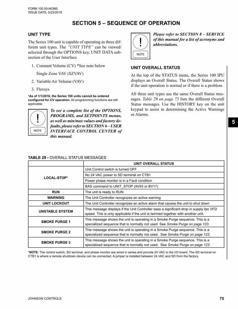
JOHNSON CONTROLS 75
FORM 100.50-NOM5 ISSUE DATE: 5/23/2018
5
SECTION 5 – SEQUENCE OF OPERATION
UNIT TYPEThe Series 100 unit is capable of operating as three dif-ferent unit types. The “UNIT TYPE” can be viewed/selected through the OPTIONS key, UNIT DATA sub-section of the User Interface.
1. Constant Volume (CV) *See note below
Single Zone VAV (SZVAV)
2. Variable Air Volume (VAV)
3. Flexsys*As of 1/1/2016, the Series 100 units cannot be ordered configured for CV operation. All programming functions are still applicable.
To see a complete list of the OPTIONS, PROGRAMS, and SETPOINTS menus, as well as min/max values and factory de-faults, please refer to SECTION 6 – USER INTERFACE CONTROL CENTER of this manual.
Please refer to SECTION 8 – SERVICE of this manual for a list of acronyms and abbreviations.
UNIT OVERALL STATUSAt the top of the STATUS menu, the Series 100 IPU displays an Overall Status. The Overall Status shows if the unit operation is normal or if there is a problem.
All three unit types use the same Overall Status mes-sages. Table 29 on page 75 lists the different Overall Status messages. Use the HISTORY key on the unit keypad to assist in determining the Active Warnings or Alarms.
TABLE 29 - OVERALL STATUS MESSAGESUNIT OVERALL STATUS
LOCAL-STOP*
Unit Control switch is turned OFFNo 24 VAC power to SD terminal on CTB1Power phase monitor is in a Fault conditionBAS command to UNIT_STOP (AV93 or BV17)
RUN The unit is ready to RUNWARNING The Unit Controller recognizes an active warning
UNIT LOCKOUT The Unit Controller recognizes an active alarm that causes the unit to shut down
UNSTABLE SYSTEM This message displays if the Unit Controller sees a significant drop in supply fan VFD speed. This is only applicable if the unit is twinned together with another unit.
SMOKE PURGE 1 This message shows the unit is operating in a Smoke Purge sequence. This is a specialized sequence that is normally not used. See Smoke Purge on page 123.
SMOKE PURGE 2 This message shows the unit is operating in a Smoke Purge sequence. This is a specialized sequence that is normally not used. See Smoke Purge on page 123.
SMOKE PURGE 3 This message shows the unit is operating in a Smoke Purge sequence. This is a specialized sequence that is normally not used. See Smoke Purge on page 123.
*NOTE: The control switch, SD terminal, and phase monitor are wired in series and provide 24 VAC to the I/O board. The SD terminal on CTB1 is where a remote shutdown device can be connected. A jumper is installed between 24 VAC and SD from the factory.

JOHNSON CONTROLS76
FORM 100.50-NOM5ISSUE DATE: 5/23/2018SECTION 5 – SEQUENCE OF OPERATION
PHASE MONITOR
2. Internal Time Clock: The unit is programmed for OCC/UNOCC times using the Internal Time Clock.
3. BAS Command: A BAS provides an OCC/UNOCC signal to the Series 100 unit.
CURRENT OPERATING MODEWithin the Current Operating mode, the unit can oper-ate in sub-modes detailed in Table 30 on page 76.
The current operating mode can be viewed in the STA-TUS menu. The Unit Controller (IPU) monitors switch-ing from a Standby mode to an Active Cooling/Heating mode. The unit must be in Standby mode for 3 minutes before switching to an Active Cooling/Heating mode.
Series 100 units have a 3-phase power monitor factory installed, except for dual point power. The phase moni-tor is wired in series between CTB1 terminal 4 and the unit control/rocker switch. It is factory set to the unit voltage, but slight field adjustment may be necessary. The location of the phase monitor varies per unit ton-nage range.
OCCUPANCY/UNOCCUPANCY DETERMINATIONThe Current Operating mode, OCC or UNOCC, is determined in one of three ways. The three ways are listed below in order of priority:
1. Hardwired: a 24 VAC input is provided to CTB1 at terminal OCC. Please note that the 24 VAC MUST be provided by the Series 100 unit.
50-65 Ton Phase Monitor
70-105 Ton Phase Monitor
120-150 Ton Phase Monitor
LD27233, LD27234, LD27235
FIGURE 33 - PHASE MONITORS
TABLE 30 - CURRENT OPERATING MODECURRENT
OPERATING MODEUNIT TYPE DESCRIPTION
OCCUPIED STANDBY
ALL There is no demand for cooling, heating, or dehumidification
OCCUPIED COOLING
VAVThere is a demand for cooling. The current RAT is 0.5°F above the "ACTIVE RAT COOLING" setpoint
OCCUPIED COOLING LOW
SZVAVThere is a demand for low cooling. The current zone temperature is 0.5°F above the "ACTIVE OCC ZONE COOLING" setpoint
OCCUPIED COOLING HIGH
SZVAVThere is a demand for high cooling. The current zone temperature is 1.5°F above the "ACTIVE OCC ZONE COOLING" setpoint
OCCUPIED COOLING W/O
BYPASSFLEXSYS
There is a demand for cooling. This mode is only used for Flexsys unit type. Please see Flexsys Operation on page 119 for a more detailed explanation
OCCUPIED COOLING W/
BYPASSFLEXSYS
There is a demand for cooling. This mode is only used for Flexsys unit type. Please see Flexsys Operation on page 119 for a more detailed explanation
OCCUPIED HEATINGVAV or
FLEXSYSThere is a demand for heating. The current RAT is 0.5°F below the "ACTIVE RAT HEATING" setpoint

JOHNSON CONTROLS 77
SECTION 5 – SEQUENCE OF OPERATIONFORM 100.50-NOM5 ISSUE DATE: 5/23/2018
5
CURRENT OPERATING MODE
UNIT TYPE DESCRIPTION
OCCUPIED HEATING LOW
SZVAVThere is a demand for low heating. The current zone temperature is 0.5°F below the "ACTIVE OCC ZONE HEATING" setpoint
OCCUPIED HEATING HIGH
SZVAVThere is a demand for high heating. The current zone temperature is 0.5°F below the "ACTIVE OCC ZONE HEATING" setpoint
UNOCCUPIED STANDBY
ALL There is no demand for cooling, heating, or dehumidification
UNOCCUPIED COOLING
VAV or FLEXSYS
There is a demand for cooling. The current zone temperature is 0.5°F above the "UNOCC ZONE COOLING" setpoint
UNOCCUPIED COOLING LOW
SZVAVThere is a demand for low cooling. The current zone temperature is 0.5°F above the "ACTIVE UNOCC ZONE COOLING" setpoint
UNOCCUPIED COOLING HIGH
SZVAVThere is a demand for high cooling. The current zone temperature is 1.5°F above the "ACTIVE UNOCC ZONE COOLING" setpoint
UNOCCUPIED HEATING
VAV or FLEXSYS
There is a demand for heating. The current zone temperature is 0.5°F below the "UNOCC ZONE HEATING" setpoint
UNOCCUPIED HEATING LOW
SZVAVThere is a demand for low heating. The current zone temperature is 0.5°F below the "ACTIVE UNOCC ZONE HEATING" setpoint
UNOCCUPIED HEATING HIGH
SZVAVThere is a demand for high heating. The current zone temperature is 0.5°F below the "ACTIVE UNOCC ZONE HEATING" setpoint
COMFORT VENT COOLING
SZVAVThere is a demand for cooling. See Ventilation on page 111 for a more detailed description
COMFORT VENT HEATING
SZVAVThere is a demand for heating. See Ventilation on page 111 for a more detailed description
MORNING WARM-UP ALLThere is a demand for heating. See Heating Operation on page 100 for a more detailed description
OCCUPIED DEHUM W/ COOLING
VAV There is a demand for dehumidification. The current % relative humidity is greater than the "ACTIVE RARH" setpoint +2%
OCCUPIED DEHUM COOL LOW
SZVAVThere is a demand for low dehumidification. The current % relative humidity is greater than the "ACTIVE RARH" setpoint +2% and there is no demand for sensible cooling or a demand for low cooling
OCCUPIED DEHUM COOL HIGH
SZVAVThere is a demand for high dehumidification. The current % relative humidity is greater than the "ACTIVE RARH" setpoint +2% and there is a demand for high cooling
UNOCCUPIED DEHUM W/ COOLING
VAVThere is a demand for dehumidification. The current % relative humidity is greater than the "ACTIVE RARH" setpoint +2%
UNOCCUPIED DEHUM COOL LOW
SZVAVThere is a demand for low dehumidification. The current % relative humidity is greater than the "ACTIVE RARH" setpoint +2% and there is no demand for sensible cooling or a demand for low cooling
UNOCCUPIED DEHUM COOL HIGH
SZVAVThere is a demand for high dehumidification. The current % relative humidity is greater than the "ACTIVE RARH" setpoint +2% and there is a demand for high cooling
Single Zone VAV (SZVAV) ModeA “SINGLE ZONE VAV” unit will be controlled by one of three “CONTROL METHODS.”
• “STAGED” (Thermostat wired into CTB1 or BAS Commands)
• “WIRED ZONE TEMP” (Hardwired sensor to CTB1)
• “COMM ZONE TEMP” (Zone temperature sig-nal from a BAS)
The “CONTROL METHOD” is selected through the OPTIONS key under the UNIT DATA subsection.
TABLE 30 - CURRENT OPERATING MODE (CONT'D)

JOHNSON CONTROLS78
FORM 100.50-NOM5ISSUE DATE: 5/23/2018SECTION 5 – SEQUENCE OF OPERATION
Staged Input• The Series 100 unit can be controlled by a stan-
dard 2 stage cooling/heating thermostat
• The 24 VAC to the thermostat MUST be provided by the Series 100 unit
• Thermostat connections is the standard connec-tions: G, Y1, Y2, W1, W2
• A BAS can also provide thermostat commands
• The following setpoints must be programmed for Staged Input
• 1st and 2nd Stage Cooling setpoints
• 1st and 2nd Stage Heating setpoints
Zone Temperature Control• The Series 100 unit can be controlled by a zone
temp sensor (10K Type III thermistor)
• Zone temp sensor can either be Hardwired to CTB1 or communicated from a BAS
• Hardwired: "CONTROL METHOD" set to "WIRED ZONE TEMP"
• Communicated from BAS: "CONTROL METH-OD" set to "COMM ZONE TEMP"
• If Zone Temperature Control is selected but no zone temperature is provided or the wrong type is selected, the unit will display a Sensor/Misc fault and will LOCKOUT.
The following values must be set for Zone Tempera-ture Control:
• "OCC ZONE COOLING" setpoint
• "UNOCC ZONE COOLING" setpoint
• "OCC ZONE HEATING" setpoint
• "UNOCC ZONE HEATING" setpoint
• 1st and 2nd Stage Cooling setpoint
• 1st and 2nd Stage Heating setpoint
Variable Air Volume (VAV)
Occupied• Supply fan is ON, controlled to "DUCT STATIC
PRESS" setpoint
• Series 100 unit monitors RAT and compares it to "RAT COOLING" setpoint and "RAT HEATING" setpoint
• In VAV mode, the Series 100 unit can operate with no external control signals
Unoccupied• Supply Fan is OFF
• Series 100 unit monitors the zone temperature and compares it the "UNOCC ZONE COOLING" and "UNOCC ZONE HEATING" setpoints
• "NIGHT SET BACK" MUST be enabled for Unocc Cooling/Heating to operate
• Unit MUST have a valid zone temperature. If there is not a valid zone temperature, the unit will display a Sens/Misc fault and will LOCKOUT.
ACTIVE MODE DETERMINATIONThe Series 100 unit uses different methods to deter-mine the active mode of operation. The different meth-ods are listed below.
Occupied Standby or Unoccupied Standby
• There is no demand for cooling or heating based on the "UNIT TYPE" selected.
• Check the "UNIT TYPE" and see if a setpoint may need to be adjusted.

JOHNSON CONTROLS 79
SECTION 5 – SEQUENCE OF OPERATIONFORM 100.50-NOM5 ISSUE DATE: 5/23/2018
5
SZVAV
Staged• 24 VAC input from a thermostat to CTB1
• "OCC COOLING LOW": 24 VAC to Y1
• "OCC COOLING HIGH": 24 VAC to Y2
• "OCC HEATING LOW": 24 VAC to W1
• "OCC HEATING HIGH": 24 VAC to W2
• Thermostat commands can also be given from a BAS
• Occupancy is determined by 24 VAC to CTB1 ter-minal OCC, Internal Time Clock, or Occupancy Command from BAS
• UNOCC modes are determined the same way as OCC modes
Zone Sensor• Either hardwired to CTB1 or communicated from
a BAS
• "OCC COOLING LOW": 0.5 °F above "OCC ZONE COOLING" setpoint
• "OCC COOLING HIGH": 1.5 °F above setpoint
• "OCC HEATING LOW": 0.5 °F below "OCC ZONE HEATING" setpoint
• "OCC HEATING HIGH": 1.5 °F below setpoint
• Occupancy determined same as staged above
• UNOCC modes are determined the same as OCC modes
TABLE 31 - SZVAV: OPERATIONAL MODE (STAGED INPUT)Y1
LOW COOL
Y2 HIGH COOL
W1 LOW HEAT
W2 HIGH HEAT
CURRENT OPER MODE
UNIT MODE
On Off Off Off Occupied Occupied Cooling LowOn/Off On Off Off Occupied Occupied Cooling High
Off Off On Off Occupied Occupied Heating LowOff Off On/Off On Occupied Occupied Heating HighOff Off Off Off Occupied Occupied Standby (See Comfort Ventilation on page 114)On Off Off Off Unoccupied Unoccupied Cooling Low
On/Off On Off Off Unoccupied Unoccupied Cooling HighOff Off On Off Unoccupied Unoccupied Heating LowOff Off On/Off On Unoccupied Unoccupied Heating HighOff Off Off Off Unoccupied Unoccupied Standby
FIGURE 34 - OPERATIONAL MODE (SZVAV STAGED INPUT)
ZONE
SETPOINT
COOLING
LOW
OCC STANDBYZONE TEMP IS LESS THAN .5 °F ABOVE ZONE TEMP SP
SUPPLY FAN AT 100%
COOLING
HIGH
OCC COOLING LOWZONE TEMP IS BETWEEN .5 °F AND 1.5 °F ABOVE THE ZONE TEMP SP
SUPPLY FAN AT 100%
OCC COOLING HIGHZONE TEMP IS MORE THAN 1.5 °F ABOVE THE ZONE TEMP SP
SUPPLY FAN AT 100%
OCC STANDBYZONE TEMP IS LESS THAN .5 °F BELOW ZONE TEMP SP
SUPPLY FAN AT 100%
HEATING
LOW
HEATING
H IGH
OCC HEATING LOWZONE TEMP IS BETWEEN .5 °F AND 1.5 °F BELOW ZONE TEMP SP
SUPPLY FAN AT 100%
OCC HEATING HIGHZONE TEMP IS MORE THAN 1.5 °F BELOW THE ZONE TEMP SP
SUPPLY FAN AT 100%
NOTES:1- WHENEVER THE UNIT ENTERS AN ACTIVE COOLING OR HEATING MODE, THE UNIT CONTROLLER WILL UTILIZE AS MANY OR AS FEW STAGES OF COOLING or HEATING THAT IT NEEDS TO ACHIEVE AND MAINTAIN THE ACTIVE SUPPLY AIR TEMP SP.
2- UNOCCUPIED SEQUENCE WILL BE THE SAME AS ABOVE EXCEPT THE ZONE TEMP SPs USED WILL BE THE UNOCC SP’s VALUES.
3- UNIT MODES WILL STAGE DOWN WHEN THE ZONE TEMP IS .5 °F UNDER SPs FOR COOLING AND .5 °F OVER SPs FOR HEATING. LD010572
NOTES:
1- WHENEVER THE UNIT ENTERS AN ACTIVE COOLING OR HEATING MODE, THE UNIT CONTROLLER WILL UTILIZE AS MANY OR AS FEW STAGES OF COOLING or HEATING THAT IT NEEDS TO ACHIEVE AND MAINTAIN THE ACTIVE SUPPLY AIR TEMP SP.
2-UNOCCUPIED SEQUENCE WILL BE THE SAME AS ABOVE EXCEPT THE ZONE TEMP SP’s USED WILL BE THE UNOCC SP’s VALUES.
3-SUPPLY FAN WILL BE STAGED ON/OFF WITH A COOLING OR HEATING DEMAND UNLESS CONTINUOUS VENTILATION IS USER ENABLED OR A CALL FOR G.
OCC HEATING HIGHDEMAND FOR W2 FROM EITHER THERMOSTAT OR BAS
SUPPLY FAN AT 100%OCC HEATING LOWDEMAND FOR W1 FROM EITHER THERMOSTAT OR BAS
SUPPLY FAN AT 100% OCC STANDBYNO DEMAND FOR HEATING FROM EITHER THERMOSTAT OR BAS
SUPPLY FAN OFF (SEE NOTE 3)
OCC STANDBYNO DEMAND FOR COOLING FROM EITHER THERMOSTAT OR BAS
SUPPLY FAN OFF (SEE NOTE 3)
OCC COOLING LOWDEMAND FOR Y1 FROM EITHER THERMOSTAT OR BAS
SUPPLY FAN AT SZVAV MINIMUM SPEED OR (IF CV) 100%
OCC COOLING HIGHDEMAND FOR Y2 FROM EITHER THERMOSTAT OR BAS
SUPPLY FAN AT 100%

JOHNSON CONTROLS80
FORM 100.50-NOM5ISSUE DATE: 5/23/2018SECTION 5 – SEQUENCE OF OPERATION
FIGURE 35 - OPERATIONAL MODE: SINGLE ZONE VAV (ZONE TEMPERATURE CONTROL)
ZONE
SETPOINT
COOLING
LOW
OCC STANDBYZONE TEMP IS LESS THAN .5 °F ABOVE ZONE TEMP SP
SUPPLY FAN AT SZVAV MIN SP
COOLING
HIGH
OCC COOLING LOWZONE TEMP IS BETWEEN .5 °F AND 1.5 °F ABOVE THE ZONE TEMP SP
SUPPLY FAN AT SZVAV MIN SP
OCC COOLING HIGHZONE TEMP IS MORE THAN 1.5 °F ABOVE THE ZONE TEMP SP
SUPPLY FAN SPEED STARTS TO INCREASE.SUPPLY FAN AT 100% WHEN THE ZONE TEMP IS MORE THAN 2.5 °F ABOVE THE ZONE TEMP SP
OCC STANDBYZONE TEMP IS LESS THAN .5 °F BELOW ZONE TEMP SP
SUPPLY FAN AT SZVAV MIN SP
HEATING
LOW
HEATING
HIGH
OCC HEATING LOWZONE TEMP IS BETWEEN .5 °F AND 1.5 °F BELOW ZONE TEMP SP
SUPPLY FAN AT 100%
OCC HEATING HIGHZONE TEMP IS MORE THAN 1.5 °F BELOW THE ZONE TEMP SP
SUPPLY FAN AT 100%
NOTES:1- WHENEVER THE UNIT ENTERS AN ACTIVE COOLING OR HEATING MODE, THE UNIT CONTROLLER WILL UTILIZE AS MANY OR AS FEW STAGES OF COOLING or HEATING THAT IT NEEDS TO ACHIEVE AND MAINTAIN THE ACTIVE SUPPLY AIR TEMP SP.
2- UNOCCUPIED SEQUENCE WILL BE THE SAME AS ABOVE EXCEPT THE ZONE TEMP SPs USED WILL BE THE UNOCC SP’s VALUES.
3- UNIT MODES WILL STAGE DOWN WHEN THE ZONE TEMP IS .5 °F UNDER SPs FOR COOLING AND .5 °F OVER SPs FOR HEATING. LD19888
Variable Air VolumeIn the OCC mode, the Active mode will be determined by the Current RAT.
• "OCC STANDBY": RAT is between the "RAT COOLING" and "RAT HEATING" setpoints
• "OCC COOLING": RAT is greater than the "RAT COOLING" setpoint by 0.5 °F
• "OCC HEATING": RAT is less than the "RAT HEATING" setpoint by 0.5 °F
In the UNOCC mode, the Active mode will be deter-mined by the zone temperature
• "UNOCC STANDBY": Zone temperature is be-tween the "UNOCC ZONE COOLING" and "UNOCC ZONE HEATING" setpoints
• "UNOCC COOLING": Zone temperature is great-er than the "UNOCC ZONE COOLING" setpoint by 0.5 °F
• "UNOCC HEATING": Zone temperature is less than the "UNOCC ZONE HEATING" setpoint by 0.5 °F
• "NIGHT SET BACK" MUST be enabled for Unocc Cooling/Heating to operate
• Unit MUST have a valid zone temperature, or it shows a Sensor/Misc fault and will not operate
The "RAT COOLING" setpoint and "RAT HEATING" setpoint cannot be closer than 2.0 °F, and the setpoints are not self adjusting. If the "RAT COOL-ING" setpoint needs lowered, the "RAT HEATING" setpoint may need lowered first. If the "RAT HEATING" setpoint needs raised, the "RAT COOLING" setpoint may need raised first.
NOTES:
1- WHENEVER THE UNIT ENTERS AN ACTIVE COOLING OR HEATING MODE, THE UNIT CONTROLLER WILL UTILIZE AS MANY OR AS FEW STAGES OF COOLING or HEATING THAT IT NEEDS TO ACHIEVE AND MAINTAIN THE ACTIVE SUPPLY AIR TEMP SP.
2- SUPPLY FAN WILL BE STAGED ON/OFF WITH A COOLING OR HEATING DEMAND UNLESS CONTINUOUS VENTILATION IS USER ENABLED OR A CALL FOR G
3- UNIT MODES WILL STAGE DOWN WHEN THE ZONE TEMP IS 0.5°F UNDER SETPOINTS FOR COOLING AND 0.5°F OVER SETPOINTS FOR HEATING
OCC STANDBYNO DEMAND FOR HEATING FROM A ZONE SENSOR
SUPPLY FAN OFF (SEE NOTE 2)
OCC STANDBYNO DEMAND FOR COOLING FROM A ZONE SENSOR
SUPPLY FAN OFF (SEE NOTE 2)
OCC COOLING LOWZONE TEMP IS BETWEEN .5 deg F AND 1.5 deg F ABOVE THE ZONE TEMP SP
SUPPLY FAN AT SZVAV MINIMUM SPEED OR (IF CV) 100%
OCC COOLING HIGHZONE TEMP IS MORE THAN 1.5 °F ABOVE THE ZONE TEMP SP.
SUPPLY FAN SPEED STARTS TO INCREASE.
SUPPLY FAN AT 100% WHEN THE ZONE TEMP IS MORE THAN 2.5 °F ABOVE THE ZONE TEMP SP
SUPPLY FAN AT 100%
OCC HEATING LOWZONE TEMP IS BETWEEN .5 °F AND 1.5 °F BELOW ZONE TEMP SP
SUPPLY FAN AT 100%
OCC HEATING HIGHZONE TEMP IS MORE THAN 1.5 °F BELOW THE ZONE TEMP SP.
SUPPLY FAN AT 100%

JOHNSON CONTROLS 81
SECTION 5 – SEQUENCE OF OPERATIONFORM 100.50-NOM5 ISSUE DATE: 5/23/2018
5
R
A
T
S
E
T
P
O
I
N
T
OCC
COOLING
OCC
HEAT ING
NOTES:
1 - WHENEVER THE UNIT ENTERS AN ACTIVE COOLING OR HEATING MODE, THE UNIT CONTROLLER WILL UTILIZE AS MANY OR AS FEW STAGES OF COOLING or HEATING THAT IT
NEEDS TO ACHIEVE AND MAINTAIN THE ACTIVE SUPPLY AIR TEMP SP.
2 - UNIT MODES WILL STAGE DOWN WHEN THE ZONE TEMP IS 0.5 °F UNDER SPs FOR COOLING AND .5 °F OVER SPs FOR HEATING.
OCC STANDBY:THERE IS NO DEMAND
FOR COOLING BASED
ON THE ACTIVE RAT
COOLING SP.
SUPPLY FAN IS BEING
CONTROLLED TO THE
ACTIVE DUCT STATIC SP
OCC COOLING:CURRENT RAT IS MORE
THAN THE ACTIVE
COOLING RAT SP + 0.5 °F.
SUPPLY FAN IS BEING
CONTROLLED TO THE
ACTIVE DUCT STATIC SP
OCC STANDBY:THERE IS NO DEMAND
FOR HEATING BASED
ON THE ACTIVE RAT
HEATING SP.
SUPPLY FAN IS BEING
CONTROLLED TO THE
ACTIVE DUCT STATIC SP
OCC HEATING:CURRENT RAT IS MORE
THAN THE ACTIVE
HEATING RAT SP MINUS 0.5 °F. SUPPLY FAN IS BEING
CONTROLLED TO THE
ACTIVE DUCT STATIC SP
Variable Air Volume (VAV)
LD20073
FIGURE 36 - OPERATIONAL MODE: VAV
SUPPLY FAN OPERATIONThe supply fan is an integral part of the Series 100 unit. The supply fan MUST be on, and the supply fan prov-ing circuit MUST be closed before any other unit op-eration is allowed.
Supply Fan Proving Circuit• Same circuit for all unit types
• An air pressure switch closes when the supply fan starts and builds up enough pressure
• Once the supply fan output switches to ON, the air proving switch must be closed within 45 seconds
• If Supply Fan Proving Circuit is not made, unit will LOCKOUT
• If the Supply Fan Proving Circuit opens at any time during normal operation, the unit will LOCKOUT
Constant Volume• No VFD
• Supply fan will start with 24 VAC input to “G” terminal on CTB1
• Supply fan will start with BAS command to FAN (G) point
• Supply fan will cycle ON with a 24 VAC input or BAS command to Y1, Y2, W1, or W2. When the 24 VAC input or BAS command is removed, sup-ply fan will cycle OFF
• Supply fan will cycle ON when a zone tempera-ture input (hardwired or BAS) energizes heating or cooling. Supply fan will cycle OFF when zone temperature input de-energizes heating or cooling
• Supply fan will run continuously in the OCC mode when "CONTINUOUS VENT" is enabled
• Supply fan will start when the unit is in "MORN-ING WARM UP"
Single Zone VAV• Unit will have a factory installed and programmed
VFD
• Supply fan will start with a demand for OCC or UNOCC cooling or heating
• Supply fan will run whenever the unit is in OCC if Continuous Ventilation is USER ENABLED
• Supply fan will start when the unit is in "MORN-ING WARM UP"

JOHNSON CONTROLS82
FORM 100.50-NOM5ISSUE DATE: 5/23/2018SECTION 5 – SEQUENCE OF OPERATION
• Supply fan speed will be determined by the Unit mode
• "OCC STANDBY": No demand for cooling or heating. Supply fan at "SZVAV MIN SPEED" setpoint.
• "OCC COOLING LOW": Current Zone Tem-perature is more than 0.5 °F higher than the "ZONE TEMP" setpoint. Supply fan VFD at "SZVAV MIN SPEED" setpoint.
• "OCC COOLING HIGH": Current Zone Temperature is more than 1.5 °F higher than
the "ZONE TEMP" setpoint. Supply fan VFD starts to speed up according to current Zone Temperature. Supply fan VFD will be at 100% when current Zone Temperature is 2.5°F above "ZONE TEMP" setpoint.
• "OCC HEATING LOW" and "OCC HEAT-ING HIGH": Supply fan will be at 100%
• UNOCC modes are the same as the above OCC modes
• SZVAV Min Speed is user adjustable
TABLE 32 - SUPPLY FAN VFD SPEED DETERMINATION∆TOC OCC
COOL
∆TOH OCC HEAT
∆TUC UNOCC COOL
∆TUH UNOCC HEAT
OCCUPANCY MODE UNIT MODE SUPPLY FAN VFD
SPEED
> 0.5 °F --- --- --- Occupied Occupied Cooling Low SZVAV Min Speed> 1.5 °F --- --- --- Occupied Occupied Cooling High SZVAV Min Speed> 2.5 °F --- --- --- Occupied Occupied Cooling High 100%
--- < -0.5 °F --- --- Occupied Occupied Heating Low 100%--- < -1.5 °F --- --- Occupied Occupied Heating High 100%
--- --- --- --- OccupiedOccupied Standby (See Comfort
Ventilation on page 114)SZVAV Min Speed
--- --- > 0.5 °F --- Unoccupied Unoccupied Cooling Low SZVAV Min Speed--- --- > 1.5 °F --- Unoccupied Unoccupied Cooling High SZVAV Min Speed--- --- > 2.5 °F Unoccupied Unoccupied Cooling High 100%--- --- --- < -0.5 °F Unoccupied Unoccupied Heating Low 100%--- --- --- < -1.5 °F Unoccupied Unoccupied Heating High 100%--- --- --- --- Unoccupied Unoccupied Standby Off
Variable Air Volume• Unit will have a factory installed and programmed
VFD
• Supply fan will operate continuously when in OCC mode
• Supply fan will start when the unit is in either "UNOCC COOLING" or "UNOCC HEATING"
• Supply fan VFD will control the supply fan to maintain the "ACTIVE DUCT STATIC PRES-SURE" setpoint
• Must set "DUCT STATIC RESET LOW" setpoint and "DUCT STATIC RESET HIGH" setpoint: SETPOINTS key / SUPPLY SYSTEMS subsec-tion
• "DUCT STATIC OVERPRESSURE" setpoint: Factory default is 3.00 ”W.C.
Supply Fan ControlOnce the supply fan is running, the speed will be con-trolled to the "ACTIVE DUCT STATIC PRESSURE" setpoint. The duct static transducer will monitor the duct static pressure and send a 0–5 VDC signal to the Unit Controller. The Unit Controller then compares the current duct static pressure to the "ACTIVE DUCT STATIC PRESSURE" setpoint. The Unit Controller will send a 0–10 VDC to the supply fan VFD to control the speed accordingly.
Duct Static Pressure Reset• The Series 100 unit can reset the "ACTIVE DUCT
STATIC PRESSURE" setpoint by utilizing the "DUCT STATIC RESET SCHEDULE"
• If one constant static pressure is required, set both "DUCT STATIC RESET LOW" and "DUCT STAT-IC RESET HIGH" setpoints at same value

JOHNSON CONTROLS 83
SECTION 5 – SEQUENCE OF OPERATIONFORM 100.50-NOM5 ISSUE DATE: 5/23/2018
5
• A 0–5 VDC signal to CTB1 or a 0–100 (%) com-mand from BAS will reset the "ACTIVE DUCT STATIC PRESSURE" setpoint
• 0 VDC or a 0 (%) BAS command will utilize the "DUCT STATIC RESET HIGH" setpoint
• 5 VDC or a 100 (%) BAS command will utilize the "DUCT STATIC RESET LOW" setpoint
• A VDC in between 0–5 VDC or a BAS com-mand between 0–100 (%) will reset "ACTIVE DUCT STATIC PRESSURE" setpoint somewhere between the "DUCT STATIC RESET LOW" and "DUCT STATIC RESET HIGH" setpoints
• When using the BAS commands, the percent of reset will be from the High setpoint (0%) down to the Low setpoint (100%). Example: High setpoint of 2.00 ”W.C. and Low setpoint of 1.00 ”W.C. A 25% command will reset the "ACTIVE DUCT STATIC PRESSURE" setpoint to 1.75 ”W.C. A command of 75% would reset the "ACTIVE DUCT STATIC PRESSURE" setpoint to 1.25 ”W.C.
• “DUCT PRES RST BAS” must be enabled in SERVICE key to utilize reset from BAS
5 Volts0 VoltsDuct Static Pres Rst
Voltage(Volts DC)
DSP SetpointActive
DUCT STATIC RESETHIGH SETP
DUCT STATIC RESETLOW SETP
LD10309A
FIGURE 37 - ACTIVE DSP SETPOINT VS. DUCT STATIC PRES RST VOLTAGE
The bypass VFD is a standard Variable Frequency Drive packaged with an ad-ditional set of contactors. When bypass mode is activated, contactors route power around the VFD, connecting the indoor fan motor directly to the supply voltage. At this point, the motor will go to full RPM regardless of the duct pressure signal, be-cause the VFD is out of the loop, and there is a potential for over pressuring the ducts.
The air balancer must set maximum duct static / CFM to stay within a static pres-sure that the ductwork of that installation can tolerate when the motor is at full RPM, considering that the VAV boxes, if they are part of the system, may not be full open.
If the duct system includes VAV boxes, they must be driven open in Bypass mode. Failure to do so could result in damage to the ductwork and the building structure.
Supply Fan SyncThe Series 100 units are capable of using a 0–5 VDC signal to control the supply fan VFD speed. This al-lows units that are connected in a master/satellite type configuration, also known as twinning, to maintain the same fan speed.
The 0–5 VDC signal must be provided to the below terminals on CTB1:
• 25: +5 V ("DUCT STATIC" setpoint +5 V)
• 26: DSP+ ("DUCT STATIC RESET" +)
• 27: DSP- ("DUCT STATIC RESET" -)
We do not allow a BAS command to control the supply fan VFD speed due to slow response time and possible over-pressurization of the duct system.
We recommend installing the tubing from the duct pressure transducer to the proper location in the unit ductwork. The duct pressure transducer provides the only factory installed duct over pressure device.
Sequence of Operation• "UNIT TYPE" must be configured for "VARI-
ABLE AIR VOLUME"
• Supply Fan Sync must be set to USER ENABLED
• The unit must be receiving a 0–5 VDC signal at CTB1 terminals 26 and 27
• The Unit Controller requires approximately 1 VDC to start the supply fan VFD. Once the fan is started, the below chart lists the expected speeds and speed % at different VDC inputs.
• If the VDC input drops to approximately 0.5 VDC, the fan will shut down

JOHNSON CONTROLS84
FORM 100.50-NOM5ISSUE DATE: 5/23/2018SECTION 5 – SEQUENCE OF OPERATION
• 1 VDC to start supply fan VFD; 0.5 VDC to stop supply fan VFD
• 1 VDC: 20% at approximately 32 hz
• 2VDC: 40% at approximately 40 hz
• 3 VDC: 60% at approximately 46 hz
• 4 VDC: 80% at approximately 53 hz
• 5 VDC: 100% at approximately 60 hz
ACTIVE SUPPLY AIR TEMPERATURE SETPOINTSDepending on the "UNIT TYPE" that is selected, the Series 100 units will use different setpoints for the Supply Air Temperature (SAT).
Once a Series 100 unit enters an Active Cooling or Heating mode, it will utilize as many or as few stages of cooling or heating as needed to achieve and main-tain the "ACTIVE SAT" setpoint. Since the Series 100 unit utilizes direct expansion (DX) cooling, there is logic and algorithms built into the program to pre-vent short-cycling of compressors and/or stages of heat. There will be some under and over shooting of
the "ACTIVE SAT" setpoint. This under/over shooting should normally stay within +/- 3 °F. There could be some infrequent times where this under/over shoot ap-proaches +/- 5 °F.
SZVAV and Constant Volume: Staged (Thermostat or a BAS Command)
Occupied/Unoccupied• 1st Stage Cooling setpoint:
• 24 VAC input to Y1
• BAS command to Y1
• 2nd Stage Cooling setpoint:
• 24 VAC input to Y2
• BAS command to Y2
• 1st Stage Heating setpoint:
• 24 VAC input to W1
• BAS command to W1
• 2nd Stage Heating setpoint:
• 24 VAC input to W2
• BAS command to W2
TABLE 33 - ACTIVE SAT SETPOINT DETERMINATION, STAGED INPUTY1
LOWCOOL
Y2HIGHCOOL
W1LOW HEAT
W2HIGH HEAT
OCC.MODE
UNIT MODE ACTIVE SP
On Off Off Off Occupied Occupied Cooling Low 1st stage cooling setpointOn/Off On Off Off Occupied Occupied Cooling High 2nd stage cooling setpoint
Off Off On Off Occupied Occupied Heating Low 1st stage heating setpointOff Off On/Off On Occupied Occupied Heating High 2nd stage heating setpoint
Off Off Off Off OccupiedOccupied Standby (See Comfort Ventilation on page 114)
None
On Off Off Off Unoccupied Unoccupied Cooling Low 1st stage cooling setpointOn/Off On Off Off Unoccupied Unoccupied Cooling High 2nd stage cooling setpoint
Off Off On Off Unoccupied Unoccupied Heating Low 1st stage heating setpointOff Off On/Off On Unoccupied Unoccupied Heating High 2nd stage heating setpointOff Off Off Off Unoccupied Unoccupied Standby None
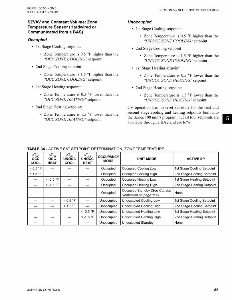
JOHNSON CONTROLS 85
SECTION 5 – SEQUENCE OF OPERATIONFORM 100.50-NOM5 ISSUE DATE: 5/23/2018
5
SZVAV and Constant Volume: Zone Temperature Sensor (Hardwired or Communicated from a BAS)
Occupied• 1st Stage Cooling setpoint:
• Zone Temperature is 0.5 °F higher than the "OCC ZONE COOLING" setpoint
• 2nd Stage Cooling setpoint
• Zone Temperature is 1.5 °F higher than the "OCC ZONE COOLING" setpoint
• 1st Stage Heating setpoint:
• Zone Temperature is 0.5 °F lower than the "OCC ZONE HEATING" setpoint
• 2nd Stage Heating setpoint:
• Zone Temperature is 1.5 °F lower than the "OCC ZONE HEATING" setpoint
Unoccupied• 1st Stage Cooling setpoint:
• Zone Temperature is 0.5 °F higher than the "UNOCC ZONE COOLING" setpoint
• 2nd Stage Cooling setpoint
• Zone Temperature is 1.5 °F higher than the "UNOCC ZONE COOLING" setpoint
• 1st Stage Heating setpoint:
• Zone Temperature is 0.5 °F lower than the "UNOCC ZONE HEATING" setpoint
• 2nd Stage Heating setpoint:
• Zone Temperature is 1.5 °F lower than the "UNOCC ZONE HEATING" setpoint
CV operation has no reset schedule for the first and second stage cooling and heating setpoints built into the Series 100 unit’s program, but all four setpoints are available through a BAS and are R/W.
TABLE 34 - ACTIVE SAT SETPOINT DETERMINATION, ZONE TEMPERATURE∆TOC OCC
COOL
∆TOH OCC HEAT
∆TUC UNOCC COOL
∆TUH UNOCC HEAT
OCCUPANCY MODE UNIT MODE ACTIVE SP
> 0.5 °F --- --- --- Occupied Occupied Cooling Low 1st Stage Cooling Setpoint> 1.5 °F --- --- --- Occupied Occupied Cooling High 2nd Stage Cooling Setpoint
--- < -0.5 °F --- --- Occupied Occupied Heating Low 1st Stage Heating Setpoint--- < -1.5 °F --- --- Occupied Occupied Heating High 2nd Stage Heating Setpoint
--- --- --- --- OccupiedOccupied Standby (See Comfort Ventilation on page 114)
None
--- --- > 0.5 °F --- Unoccupied Unoccupied Cooling Low 1st Stage Cooling Setpoint--- --- > 1.5 °F --- Unoccupied Unoccupied Cooling High 2nd Stage Cooling Setpoint--- --- --- < -0.5 °F Unoccupied Unoccupied Heating Low 1st Stage Heating Setpoint--- --- --- < -1.5 °F Unoccupied Unoccupied Heating High 2nd Stage Heating Setpoint--- --- --- --- Unoccupied Unoccupied Standby None

JOHNSON CONTROLS86
FORM 100.50-NOM5ISSUE DATE: 5/23/2018SECTION 5 – SEQUENCE OF OPERATION
Variable Air Volume
Supply Air Temperature ResetWith a Series 100 unit set up for VAV operation, there is the ability to reset the "ACTIVE SUPPLY AIR TEMP" setpoint by one of four different methods. This is for the "COOLING SAT" setpoints only.
1. Hardwired
2. Outside Air
3. Return Air
4. Supply Fan VFD Speed
The "ACTIVE SUPPLY AIR TEMP" setpoint will be maintained at or between the "SAT HIGH" and "SAT LOW" setpoints depending on which "SAT RESET METHOD" is selected and the setpoints associated with that "SAT RESET METHOD."
Hardwired SAT Reset
• A 0–5 VDC signal wired into CTB1
• A 0–5 command from a BAS
• 0 VDC or a 0 command from the BAS: the unit will utilize the "SAT HIGH" setpoint
• 5 VDC or a 5 command from the BAS: the unit will utilize the "SAT LOW" setpoint
• A VDC or command from the BAS in between 0–5: the unit will maintain a setpoint somewhere between the "SAT HIGH" and the "SAT LOW" set-points
• "SAT RESET METHOD" set to "HARDWIRED"
• "SAT RST BAS" must be enabled in the SERVICE key menus in order to communicate the 0–5 com-mand
5 Volts 0 Volts
(Default = 65.0 °F)
Supply Air Temp Rst Voltage
(Volts DC)
Active SAT Setpoint
SAT HIGH SETPOINT
(Default = 55.0 °F)
SAT LOW SETPOINT
FIGURE 38 - ACTIVE SAT SETPOINT VS. SUPPLY AIR TEMP RST VOLTAGE
LD12587
Outside Air SAT Reset
• The Series 100 unit will reset the active "COOL-ING SAT" setpoint based on the Outside Air Tem-perature (OAT)
• Must set the "OAT SETPOINT FOR HIGH SAT" and "OAT SETPOINT FOR LOW SAT": SETPOINTS key / COOLING subsection
• "SAT RESET METHOD" set to "OUTSIDE AIR"
• OAT equal to or less than the "OAT SETPOINT FOR HIGH SAT": the unit will utilize the "SAT HIGH" setpoint
• OAT equal to or greater than the "OAT SETPOINT FOR LOW SAT": the unit will utilize the "SAT LOW" setpoint
Outside Air Temp (OAT)
Active SAT Setpoint
Increasing OAT
(Default = 65.0 °F)
SAT HIGH SETPOINT
(Default = 55.0 °F)
SAT LOW SETPOINT
OAT SETPOINT FOR HIGH SAT
OAT SETPOINT FOR LOW SAT
LD12588
FIGURE 39 - ACTIVE SAT SETPOINT VS. OUTSIDE AIR TEMP

JOHNSON CONTROLS 87
SECTION 5 – SEQUENCE OF OPERATIONFORM 100.50-NOM5 ISSUE DATE: 5/23/2018
5
Return Air SAT Reset
• The Series 100 unit will reset the active "COOL-ING SAT" setpoint based on the Return Air Tem-perature (RAT)
• Must set the "RAT SETPOINT FOR HIGH SAT" and "RAT SETPOINT FOR LOW SAT": SETPOINTS key / COOLING subsection
• "SAT RESET METHOD" set to "RETURN AIR"
• RAT equal to or less than the "RAT SETPOINT FOR HIGH SAT": the unit will utilize the "SAT HIGH" setpoint
• RAT equal to or greater than the "RAT SETPOINT FOR LOW SAT": the unit will utilize the "SAT LOW" setpoint
(Default = 55.0 °F)
(Default = 65.0 °F)
Return Air Temp (RAT)
Active SAT Set Point
Increasing RAT
SAT LOW SETPOINT
SAT HIGH SETPOINT
RAT SETPOINT FOR HIGH SAT
RAT SETPOINT FOR LOW SAT
LD10307A
FIGURE 40 - ACTIVE SAT SETPOINT VS. RETURN AIR TEMP
Supply Fan VFD Speed SAT Reset
• The Series 100 unit will reset the active "SAT COOLING" setpoint based on the Supply Fan VFD Speed
• Must set the "FAN SPEED SETPOINT FOR HIGH SAT" and "FAN SPEED SP FOR LOW SAT": SETPOINTS key / COOLING subsection
• "SAT RESET METHOD" set to "SUPPLY FAN SPEED"
• VFD speed equal to or less than the "FAN SPEED SETPOINT FOR HIGH SAT": the unit will utilize the "SAT HIGH" setpoint
• VFD speed equal to or greater than the "FAN SPEED SETPOINT FOR LOW SAT": the unit will utilize the "SAT LOW" setpoint
(Default = 55.0 °F)
(Default = 65.0 °F)
Supply Fan Speed %
Active SAT Setpoint
Increasing Supply Fan Speed
SAT LOW SETPOINT
SAT HIGH SETPOINT
FAN SPEED FOR HIGH SAT
FAN SPEED FOR LOW SAT
LD10308A
FIGURE 41 - ACTIVE SAT SETPOINT VS. SUPPLY FAN SPEED
These different setpoints can be set using the Series 100 unit’s control panel or through a BAS.
The "SAT RESET METHOD" MUST be set using the unit’s control panel.
The "SAT HIGH" setpoint and "SAT LOW" setpoint are R/W points, and a separate reset method could be uti-lized using programming in the BAS.
Heating SAT Setpoint• The "HEATING SAT" setpoint has no reset sched-
ules available
• Must set the "HEATING SAT" setpoint: SETPOINTS key / HEATING subsection
• "HEATING SAT" setpoint is a R/W point through a BAS

JOHNSON CONTROLS88
FORM 100.50-NOM5ISSUE DATE: 5/23/2018SECTION 5 – SEQUENCE OF OPERATION
COMPRESSOR CONTROLWhenever a change in the unit cooling status is made:
• Compressor turned OFF, or
• Compressor turned ON,
a 3.5 minute Interstage Delay Timer is initiated. Dur-ing these 3.5 minutes, no compressor can be started or stopped normally. A compressor will still be stopped immediately if a safety fault occurs.
Compressor Control (CV, SZVAV, and VAV)1. Series 100 unit enters an Active Cooling mode
2. Unit Controller sets the “COOLING CONTROL OFFSET” to 2.0 °F
3. Unit Controller compares the SAT to the "AC-TIVE SAT" setpoint plus or minus the “COOLING CONTROL OFFSET”
4. If SAT is greater than the "ACTIVE SUPPLY AIR TEMP" setpoint plus the “COOLING CONTROL OFFSET,” Unit Controller will:
a. Start a compressor
OR
b. Bring on an additional stage of cooling based on the “NEXT STAGE TO ENABLE”
5. If SAT is less than the "ACTIVE SUPPLY AIR TEMP" setpoint minus the “COOLING CON-TROL OFFSET,” Unit Controller will:
a. Stop a compressor based on the “NEXT STAGE TO DISABLE”
Compressor Operation with Economizer• When the OA conditions are suitable for econo-
mizer operation, the Unit Controller will set the “COOLING CONTROL OFFSET” to 4.5 °F
• The “COOLING CONTROL OFFSET” will re-main at 4.5 °F as long as the OA conditions are suitable and the economizer remains active
Economizer becomes active and no compressors are operating:
1. Compressors will be started based on the “NEXT STAGE TO ENABLE” when ALL of the following are true:
a. Econ Control Output greater than 95% for 30 sec
b. SAT greater than or equal to "ACTIVE SUP-PLY AIR TEMP" setpoint plus the “COOL-ING CONTROL OFFSET” (4.5 °F)
c. 3.5 min Interstage Delay Timer has expired
2. Compressors will be stopped based on the “NEXT STAGE TO DISABLE” when ALL the following are true:
a. Econ Control Output less than 5% for 30 sec
b. SAT less than or equal to the "ACTIVE SUP-PLY AIR TEMP" setpoint minus the “COOL-ING CONTROL OFFSET” (4.5 °F)
c. 3.5 min Interstage Delay Timer has expired
Economizer becomes active and one or more compres-sors operating:
1. A compressor will be staged OFF, and the se-quence above will be utilized
Compressor StagingThe Series 100, 50-65 ton unit has two completely sepa-rate refrigeration circuits. There are two scroll compres-sors per circuit for a total of four scroll compressors.
Fast Compressor StartThe Series 100 Unit Controller will use an Optimum Stage-Up Algorithm to quickly bring on the correct numbers of compressors when changing from "OCC/UNOCC STANDBY" to "OCC/UNOCC COOLING." This sequence is called Fast Compressor Start and will work for all unit configurations.
• USER ENABLED - Unit Controller will deter-mine which stage is needed for the initial cooling demand and will start the appropriate compres-sors needed
• USER DISABLED - Unit Controller will bring on one compressor at a time with a 3.5-minute Inter-stage Delay Timer between each stage
Compressor Staging LogicThe compressor staging logic utilizes many different factors to determine the available compressors.
• Unit Size
• Compressor System Status (Normal or Faulted)

JOHNSON CONTROLS 89
SECTION 5 – SEQUENCE OF OPERATIONFORM 100.50-NOM5 ISSUE DATE: 5/23/2018
5
Current Stage1. Unit enters an Active Cooling mode
2. Unit Controller will determine the appropriate compressors to start based on the following:
a. Internal programming logic
AND
b. Status of Fast Comp Start
1. USER ENABLED
2. USER DISABLED
Economizer Available1. Unit enters an Active Cooling mode and be-
fore any compressor is started, the “CURRENT STAGE” shall be set to 0
2. If “ECON AVAILABLE” is YES and the condi-tions determine that compressors are needed, Unit Controller will start the compressors that are needed for Stage 1 and set the “CURRENT STAGE” to 1
3. Staging up/down from this point will be in a se-quential manner (Step 1, 2, 3, 2, 1 etc.)
4. “CURRENT STAGE” will be recorded each time the controller stages up/down
Economizer Not Available and Fast Compressor Start Disabled
1. Unit enters an Active Cooling mode
2. Unit Controller will set the next stage to 1, and the compressors will be started/stopped sequentially
3. Four stages
Economizer Not Available and Fast Compressor Start Enabled
1. Unit enters an Active Cooling mode
2. Unit Controller will determine the cooling stage needed for the initial cooling demand
3. Unit Controller will bring on the appropriate com-pressors needed for the initial cooling demand
4. There will be a 10 second delay between com-pressors starting for the initial cooling demand
5. Once all the appropriate compressors have been started for the initial cooling demand, the Unit Controller will:
a. Wait 3.5 minutes
b. Determine if more or less cooling is needed
c. More Cooling: will start/stop the appropriate compressors for the next higher stage
d. Less Cooling: will start/stop the appropriate compressors for the next lower stage
Changing Staging Sequences1. During an Active Cooling mode, certain condi-
tions could cause the Unit Controller to change the current staging method
a. “HOT GAS REHEAT” becomes active/inac-tive
b. One or more compressor systems develop a Fault condition
c. Comp System Fault condition is cleared
d. Economizer goes active/inactive
2. When this occurs, the Unit Controller will deter-mine the proper compressor stage for the condi-tions
3. When changing staging sequences, the Unit Con-troller will:
a. Temporarily stop the “COOLING CON-TROL OFFSET” calculation
b. Hold the current “COOLING CONTROL OFFSET” value
c. Wait until the staging sequence has completed
d. Wait until 3.5 minutes has expired
e. Resume normal operation based on the new staging sequence
COMPRESSOR STATUS AND RUN DATA
Compressor Run Data• The Unit Controller will monitor the compressor
starts and compressor run hours.
• This data will be stored under the OPERATING HOURS / START COUNTER key
• Operating hours/start counts cannot be reset
Compressor Status• Each compressor circuit will have a high and low
pressure switch

JOHNSON CONTROLS90
FORM 100.50-NOM5ISSUE DATE: 5/23/2018SECTION 5 – SEQUENCE OF OPERATION
• Some compressors will have a compressor motor protector inside the compressor electrical box, and some will just utilize an internal thermal overload
• 50 Ton Unit: All (four) compressors have in-ternal thermal overloads; no motor protectors
• 51 ton unit: All (four) compressors have in-ternal thermal overloads; no motor protectors
• 60 ton unit: Comp 1A and 2A have internal thermal overloads; 1B and 2B have motor protectors
• 61 ton unit: Comp 1A has an internal ther-mal overload; 1B, 2A, and 2B have a motor protector
• The Unit Controller will monitor several different parameters to determine the status of a compres-sor circuit
• "HIGH DP UNLOAD"
• "LOW AMB INHIBIT"
• "LOW SUCT TEMP UNL"
• "COMPR # SAFETY TRIP"
• "COMPR # SAFETY FAULT"
• "COMPR # SAFETY LOCKOUT"
• If NONE of the above conditions exist, a com-pressor will be placed in a Ready to Run state
• Once a compressor is started, after the 3.5-minute Minimum On Timer has expired, the Unit Con-troller will change a compressor status to Ready to Stop state
Compressor Safety Circuit• The Unit Controller will monitor the Compressor
Safety Circuit for each compressor system
• The Compressor Safety Circuit will include the following:
• High pressure switch
• Compressor solid state motor protector, if applicable
• The internal thermal overload is not connected to the compressor safety chain. If the internal ther-mal overload opens, the safety circuit will remain closed and no alarm will be generated.
• Each compressor circuit also has a low pressure switch and suction line temp sensor. They are
NOT a component of the Compressor Safety Cir-cuit but are still monitored and are part of deter-mining a compressor’s status. The Low Pressure Cutout (LPCO) will have its own separate fault.
Compressor Safety Circuit: Safety Trips and Safety Lockouts
• The components in the Compressor Safety Circuit are wired in series
• When all safeties are closed, there will be a 24 VAC input to the I/O board
• If any of the components open while a compressor is operating, both compressors in that circuit will be stopped (the 24 VAC input will be lost)
• The Unit Controller then monitors the time it takes for the open safety to reset and close (24 VAC input will be re-established)
• The time to reset (re-establish 24 VAC input) will be recorded in the HISTORY buffer and identified as the “COMP STATUS # CLEAR TIME”
• Compressor Solid State Motor Protector: typically 30 minutes to clear
• High Pressure Switch: typically less than 1 minute
• If the reset time is greater than 60 minutes, “COMP STATUS # CLEAR TIME” will be changed to “COMP STATUS # TIME OUT,” and a "COMP SYSTEM # – SAFETY LOCKOUT” will be generated.
Compressor System Safety Trip• Safety circuit input is ignored when both the com-
pressors of any system are OFF
• If either or both compressors are ON and the safe-ty circuit opens, the Unit Controller will turn OFF the active compressors for that circuit
• Compressor system will be made active again when the safety circuit is closed
• If Compressor Safety Circuit opens, the following will occur:
• A “COMP SYS # STATUS – SAFETY TRIP” will be stored in the HISTORY buffer
• The first safety trip will display “COMP # SAFETY TRIP 1”
• A second trip within 120 minutes will dis-play “COMP # SAFETY TRIP 2”

JOHNSON CONTROLS 91
SECTION 5 – SEQUENCE OF OPERATIONFORM 100.50-NOM5 ISSUE DATE: 5/23/2018
5
• A third trip within 120 minutes will cause the compressor system to LOCKOUT. HIS-TORY buffer will display "COMP SYSTEM # – SAFETY LOCKOUT”
• A manual reset will be required
• If 120 minutes expires before a second or third safety circuit trip, the Safety Circuit Timer will be reset.
Low Pressure Cutout• Operation of the LPCO will be the same as the
Compressor Safety Circuit except for:
• The low pressure switch will be ignored dur-ing the first 45 seconds once a compressor system starts
• The low pressure switch will be ignored when a compressor system is inactive
• Safety trips and safety lockouts will follow the same logic as above
• HISTORY buffer displays:
• "COMP # LPCO TRIP 1 OR 2"
• "COMP SYS # STATUS – SAFETY LOCK-OUT"
Resetting a Compressor System Safety Lockout
• Once a compressor system experiences either a Compressor Safety Lockout or a Compressor LPCO Safety Lockout, a manual reset will be required
• Reset a Safety Lockout by performing the follow-ing steps:
1. Leave the unit control/rocker switch ON
2. Press the COMPRESSOR SYSTEMS key
3. Use the ◄ or ► keys to navigate to the com-pressor system with the LOCKOUT
4. Use the ▲ or ▼ keys to find the screen that displays COMPRESSOR SYS # STATE – LOCKOUT
5. Press the PROGRAM key and, use the ◄ or ► keys to navigate until the top line of the display shows PROGRAM – COMPRESSOR SYSTEM #
6. Press the key and enter the password 9725, if prompted, and press the key again
7. The display should now show:
• PROGRAM–COMPRESSOR SYSTEM # TO EDIT
• COMPRESSOR SYS # STATE LOCK-OUT
8. Press the key and use the ◄ or ► keys to change from LOCKOUT to RUN, and press the key again
• If Compressor State returns to LOCK-OUT, a safety switch is still open and further troubleshooting is required
9. If Compressor State remains in RUN, press the X key and exit out of the PROGRAM – COMPRESSOR SYSTEM # MENU
10. The Compressor System Lockout has now been cleared and reset
The # symbol will be replaced by the compressor system # (e.g. 1, 2, or 3) on the actual display on the unit.
Suction Temperature Monitoring• Whenever a compressor is operating, the Unit
Controller will monitor the suction line tempera-ture for the system
• Suction line temperature falls below suction low limit, 37 °F for R-410A, for 10 seconds the Unit Controller will:
11. Display the following
a. STATUS screen: “COMP SYS # STA-TUS – LOW SUCT TEMP UNLOAD"
b. COMPRESSOR SYSTEMS screen: “STATUS LOW SUCT TEMP UNL”
c. HISTORY screen: "LOW SUCT TEMP # TRIP"
12. If both compressors were operating, Unit Controller will turn OFF the compressor with the longest run time
13. Unit Controller will start a 60-second timer
14. After 60 seconds, the Unit Controller will monitor the suction line temperature for the operating compressor

JOHNSON CONTROLS92
FORM 100.50-NOM5ISSUE DATE: 5/23/2018SECTION 5 – SEQUENCE OF OPERATION
15. If the suction line temperature falls below the suction low limit, 37 °F for R-410A, the other compressor will be turned OFF
• This fault will be cleared for each compressor when the suction line temperature is greater than the suction low limit, 37 °F for R-410A, plus 10°F for 10 minutes.
High Discharge Pressure UnloadingThis feature allows the Unit Controller to shut down compressors before the discharge pressure reaches the "HIGH PRESSURE CUT-OUT" setpoint, thus provid-ing reduced cooling for units that may have dirty con-denser coils, overcharged systems, defective condenser fan motors, or the outside ambient temperature is high-er than design conditions.
Sequence of Operation1. Unit MUST have discharge pressure transducers
installed for this feature to operate
2. “SYSTEM UNLOADING PRESSURE” MUST be set in the SETPOINTS key / COMPRESSOR SYSTEMS subsection
3. Both compressors for a compressor system MUST be operating
4. System discharge pressure greater than/equal to the “SYSTEM UNLOADING PRESSURE” setpoint for 10 seconds
5. Unit Controller will turn OFF the compressor with the fewest number of starts.
6. Unit Controller will record the OAT at time of shutting down compressor
7. The “HIGH DP UNLOAD” will be cleared when:
a. The current OAT is less than the OAT at time of trip by at least 5.0°FAND
b. The discharge pressure is less than the “SYS-TEM UNLOADING PRESSURE”
Low Ambient Operation• The Series 100, 50–65 ton units can operate me-
chanical cooling as low as 50.0°F OAT with stan-dard controls
• Mechanical cooling will be allowed to operate down to minimum 0 °F with a low ambient kit installed. "MECH COOLING LOCKOUT" tem-perature is user adjustable between 0–65°F with a low ambient kit
• Series 100, 50–65 ton units only have the option for a low ambient kit on circuit 1
• A low ambient kit will include a discharge pres-sure transducer and a condenser fan VFD
• The condenser fan VFD will control the speed of condenser fan 1A to maintain proper refrigerant pressures
• The condenser fan VFD will start at 15 hz and will start to speed up at approximately 270 psig
• Condenser fan VFD will be at 100% at approxi-mately 350 psig
HOT GAS REHEAT (SZVAV AND VAV ONLY)The Series 100 50–65 ton, Rev F unit has the option for a Hot Gas Reheat (HGRH) system. A HGRH system allows a standard DX cooling unit to dehumidify supply air.
HGRH System• HGRH is a factory installed option
• Unit has a HGRH coil installed after the standard DX evaporator coil
• Uses the refrigerant discharge gas from compres-sor circuit 2
• Reduces the amount of available cooling stages
• HGRH must be set to INSTALLED in the OP-TIONS key/UNIT DATA menu for the HGRH system to operate if installed

JOHNSON CONTROLS 93
SECTION 5 – SEQUENCE OF OPERATIONFORM 100.50-NOM5 ISSUE DATE: 5/23/2018
5
• Allows for a dehumidification sequence
• Unit Controller modulates a 3-way stepper valve to control the amount of discharge gas to the HGRH coil
• Adds sensible heat to the supply air being delivered to the space. This allows the DX evaporator coil to operate at a lower temperature and remove excess moisture without negatively affecting personal comfort
• HGRH coil has a HGRH Bleed Solenoid Valve installed
a. HGRH Bleed Solenoid Valve is connected between the HGRH coil and the CKT 2 suc-tion line
b. HGRH Bleed Solenoid Valve bleeds off any remaining/trapped oil or liquid refrigerant in the HGRH coil when HGRH is inactive
c. HGRH Bleed Solenoid Valve is normally closed and energizes whenever HGRH is in-active
• During HGRH operation, one compressor from CKT 1 and one compressor from CKT 2 always operate. Other compressors can start/stop based on demand
• HGRH is not permitted if compressor CKT 2 is not able to operate
• HGRH operation is allowed if compressor CKT 1 is inoperable
• Cannot be installed on Flexsys configured units
HRGH 3-Way Stepper Valve• The HGRH 3-way stepper valve (Figure 42 on
page 94) is controlled by its own separate con-troller (Sporlan IB-G Controller)
• The HGRH system uses a Sporlan 3-way modu-lating stepper valve (MTW-17)
• The HGRH 3-way stepper valve allows for con-trol of the refrigerant discharge gas from refriger-ant CKT 2 to either the condenser coil and/or the HGRH coil
• The stepper motor is an integral component of the HGRH 3-way stepper valve and cannot be re-placed individually
• Once energized for HGRH control, the HGRH 3-way stepper valve modulates between a mini-mum and maximum position
• Minimum Position: 25% (this is a fixed set-ting and cannot be changed)
• Maximum Position: Varies based on the cur-rent OAT. See Figure 43 on page 94.
• If OAT is less than/equal to 70.0°F, the maximum position is 50%
• If OAT is greater than/equal to 95.0°F, the maximum position is 75%
• If the OAT is between 70.0°F and 95.0°F, the maximum position is be-tween 50% and 75%
• Outlet A is piped to the condenser
• Outlet B is piped to the HGRH coil
• Inlet from discharge line CKT 2

JOHNSON CONTROLS94
FORM 100.50-NOM5ISSUE DATE: 5/23/2018SECTION 5 – SEQUENCE OF OPERATION
LD20876
FIGURE 42 - HGRH 3-WAY STEPPER VALVE
50.0%
75.0%
Outside Air Temperature
Maximum HGRH Valve
Position
95.0°F 70.0°
Increasing OAT
LD20876
FIGURE 43 - MAX HGRH VALVE POSITION VS. OAT
HGRH Control Board• The HGRH control board (Figure 44 on page
95) is factory installed and programmed. No field set-up is required
• The HGRH control board is powered by 24 VAC
• The HGRH control board receives a 0–10 VDC signal from the Unit Controller. The HGRH con-trol board uses this 0–10 VDC signal to modulate the valve open/closed through pulsed signals
• TB9 terminals 11 and 12 of the I/O board provide the 0–10 VDC signal (these terminals are used for control of the Bypass Damper on a Flexsys con-figured unit)
• The HGRH control board has three LEDs that can be used as a reference
• Red LED: The Status LED is lit when the HGRH control board has 24 VAC power
• Yellow LED: The Closed LED is only lit when the valve is fully closed
• Green LED: The Valve Open LED flashes in different sequences depending on the valve position
a. One flash: Valve position between 0–10%
b. Two flashes: Valve between 10–20%
c. Three flashes: Valve between 20–30%
d. Four through ten flashes: Follow the pattern in steps a through c
The green LED remains lit whenever the valve is fully open.
OUTLET B: TO HGRH COIL
OUTLET A: TO CONDENSER COIL
FROM DISCHARGE LINE CKT 2 B
A

JOHNSON CONTROLS 95
SECTION 5 – SEQUENCE OF OPERATIONFORM 100.50-NOM5 ISSUE DATE: 5/23/2018
5
0–10 VDC from Unit Controller
R B W & GPulse Signal from IG-B control to HGRH 3-way stepper valve
24 VAC into IB-G control board
TABLE 40 - INPUT SIGNAL (JUMPER LOCATION)
5 4 3 2 1
4-20mA 0–10V
1200Ω
1000Ω
600Ω
300Ω
TABLE 41 - NUMBER OF STEPS6386 3196 2500 1596 500
1 OFF OFF OFF OFF ON
2 OFF OFF ON ON OFF
3 OFF ON OFF ON OFF
SW1: HGRH 3-way stepper valve configuration. All switches should be set to the OFF position.
TABLE 42 - VALVE TYPE
OFF ON
4 Bipolar Unipolar
5 Std Direction Reverse
6 Std Response Quick
7 200pps 400pps
8 Std Operation Close Valve
Input signal selector Jumper set to pin 1, 0–10 VDC
LD20878 and LD20879
FIGURE 44 - HGRH CONTROL BOARD

JOHNSON CONTROLS96
FORM 100.50-NOM5ISSUE DATE: 5/23/2018SECTION 5 – SEQUENCE OF OPERATION
HGRH Bleed Solenoid Valve• 24 VAC
• The HGRH bleed solenoid valve connects the HGRH coil to the CKT 2 suction line
• Bleeds off any remaining or trapped liquid in the HGRH coil when HGRH is inactive
• The HGRH bleed solenoid valve is normally closed. It opens (energizes) whenever the HGRH system is inactive
• 5-minute delay before opening after HGRH goes inactive
Modulating HGRH 3-Way Stepper
Valve
LD20880
FIGURE 45 - HGRH PIPING LAYOUT
HGRH Setup• HGRH is a factory installed option
• Unit Controller is configured for VAV or SZVAV
• HGRH is set to INSTALLED: OPTIONS key / UNIT DATA subsection
• HGRH CONTROL is set to USER ENABLED: PROGRAM key / UNIT DATA subsection
• "EVAP AIR TEMP HIGH" and "EVAP AIR TEMP LOW" setpoints need to be entered: SETPOINTS key / COOLING subsection
• "LOW RARH" and "HIGH RARH" setpoints need to be entered: SETPOINTS key / COOLING subsection
• "HGRH SAT HIGH" and "HGRH SAT LOW" setpoints need to be entered: SETPOINTS key / COOLING subsection
• Unit has a combination RAT/humidity sensor installed
• Unit has a combination SAT/humidity sensor installed
• Unit has an evaporator leaving air temperature sensor installed (four separate sensors wired in an averaging configuration)

JOHNSON CONTROLS 97
SECTION 5 – SEQUENCE OF OPERATIONFORM 100.50-NOM5 ISSUE DATE: 5/23/2018
5
HGRH StatusThe HGRH system status shows as one of the five states listed below:
User Disabled• HRGH Control is set to USER DISABLED either
at the Unit Controller or through the BAS
Inactive If any of the below requirements are satisfied:
• There is no demand for dehumidification
• Current OAT is less than 54.0°F
• "EVAP AIR TEMP ACTIVE" setpoint is great-er than or equal to the "HGRH SAT ACTIVE" setpoint minus 4.0°F and HGRH valve position is less than or equal to the HGRH valve minimum position plus 5%
Ready All of the below requirements are satisfied:
• A demand for dehumidification exists
• Waiting for time delays to expire before becoming active
Active • All of the conditions for READY are satisfied
• HGRH system is active and functioning properly
Faulted• The Unit Controller determines there is an active
HGRH fault
HGRH Sequence of Operation• HGRH is set to INSTALLED
• HGRH Control is set to USER ENABLED
• HGRH can operate in both OCC and UNOCC modes. If unoccupied dehumidification is re-quired, "NIGHT SET BACK" must be USER EN-ABLED. PROGRAM key / UNIT DATA subsec-tion
• OAT is greater than or equal to 55.0°F
• If the active RA humidity is greater than the ac-tive "LOW RARH" setpoint plus 2% relative hu-miditiy, HGRH becomes READY
• The IPU starts a compressor from either CKT 1 or CKT 2
• Approximately 15 seconds later, the IPU starts a compressor from the CKT not se-lected in the previous step
• Approximately 215 seconds later, the HGRH system becomes active
• When HGRH is active, the compressors are con-trolled to the "EVAP AIR TEMP ACTIVE" setpoint (see Figure 46 on page 97)
• When HGRH is active, the HGRH valve is modu-lated open or closed to achieve and maintain the HGRH "SAT ACTIVE" setpoint (see Figure 47 on page 98)
• HGRH remains active until the active RA Humid-ity is less than the active "LOW RARH" setpoint minus 2% relative humidity
EVAP AIR TEMP HIGH SETPOINT
Return Air-HumidityActive
Increasing RARH
EVAP AIR TEMP
EVAP AIR TEMP LOW SETPOINT
LOW RARHSETPOINT
HIGH RARHSETPOINT
Active Setpoint
LD20881
FIGURE 46 - EVAP AIR TEMP ACTIVE SETPOINT VS RETURN AIR HUMIDITY

JOHNSON CONTROLS98
FORM 100.50-NOM5ISSUE DATE: 5/23/2018SECTION 5 – SEQUENCE OF OPERATION
HGRH SAT LOW SETPOINT
HGRH SAT HIGH SETPOINT
Return Air Temperature (RAT)
HGRH SAT Active
Setpoint
~RAT COOLINGSETPOINT-2.0°F
Increasing RAT
~RAT COOLINGSETPOINT-1.0°F
LD21611
FIGURE 47 - HGRH SAT ACTIVE SETPOINT VS RETURN AIR TEMPERATURE
HGRH Faults1. HGRH Fault 1: All the below conditions have
been active for 5 minutes
a. HGRH is INSTALLED
b. HGRH Status is INACTIVE
c. Any compressor from CKT 2 is ON
d. Current SAT is greater than or equal to "CURRENT EVAP AIR TEMP" setpoint plus 8.0°F for more than 5 minutes
2. HGRH Fault 2: All the below conditions have been active for 5 minutes
a. HGRH is INSTALLED
b. HGRH Status is ACTIVE
c. HGRH valve position is greater than or equal to 50%
d. Current SAT is less than or equal to "CUR-RENT EVAP AIR TEMP" setpoint plus 8.0°F for more than 5 minutes
If any of the previous fault conditions exist, the Unit Controller:
1. Turns off Comp 2A or 2B if they are running
2. Displays HGRH Status as FAULTED
3. Displays a COOLING/HEATING FAULT
4. Displays a LOCKOUT-COMPRESSOR SYSTEM 2
The LOCKOUT-COMPRESSOR SYSTEM 2 can-not clear until the HGRH Status is not FAULTED
• Once HGRH is active, a compressor from each CKT remains in operation until the dehumidifica-tion demand is no longer present AND as long as no compressor faults occur
User has the option of using the factory installed RA humidity sensor for the ac-tive humidity value or providing a zone humidity value from the BAS.
If the zone humidity BAS value is greater than 5% relative humidity, the zone hu-midity BAS value is used to determine dehumidification demand. If the zone humidity value is less than 5% relative humidity, RA humidity value is used to determine dehumidification demand.
HGRH Current Operating Modes• "OCC DEHUM WITH COOL" (VAV)
• "OCC DEHUM COOL HI" (SZVAV)
• "OCC DEHUM COOL LO" (SZVAV)
• "UNOCC DEHUM W/ COOL" (VAV)
• "UNOCC DEHUM COOL HI" (SZVAV)
• "UNOCC DEHUM COOL LO" (SZVAV)

JOHNSON CONTROLS 99
SECTION 5 – SEQUENCE OF OPERATIONFORM 100.50-NOM5 ISSUE DATE: 5/23/2018
5
CONDENSER FAN CONTROLThe Series 100, 50–65 ton unit has four condenser fans. The Unit Controller will cycle condenser fans ON/OFF based on OAT, number of compressors ON per system, and the current discharge pressure (if applicable).
Ambient ControlWhenever a compressor is cycled ON, a condenser fan output will be turned ON. The number of condenser fans running at any given time will be based on the following tables.
TABLE 35 - ONE COMPRESSOR ON PER ANY SYSTEM
OUTSIDE AIR TEMPCONDENSER FAN OUTPUT1A 1B 2A 2B
-20.0 °F THRU 59.0 °F ON OFF OFF OFF
60.0 °F THRU 79.0 °F ON ON OFF OFF
80.0 °F THRU 89.0 °F ON ON ON OFF
90.0 °F THRU 181.0 °F ON ON ON ON
TABLE 36 - TWO COMPRESSOR ON PER ANY SYSTEM
OUTSIDE AIR TEMPCONDENSER FAN OUTPUT
1A 1B 2A 2B
-20.0 °F THRU 59.0 °F ON OFF OFF OFF
60.0 °F THRU 72.0 °F ON ON OFF OFF
73.0 °F THRU 79.0 °F ON ON ON OFF
80.0 °F THRU 181.0 °F ON ON ON ON
Ambient Plus Discharge Pressure ControlIf the compressor system has a discharge pressure transducers installed, the condenser fans will be staged ON/OFF per the above tables AND the refrigerant dis-charge pressure.
• "PRESS TRANS PKG" must be set to the appro-priate value: SYS 1 or SYS 1,2
• When a compressor system initially starts, the condenser fans will be controlled per the above tables
• After 5 minutes has passed allowing the refriger-ant pressures to stabilize, the Unit Controller will monitor the discharge pressure for any system that has a discharge pressure transducer installed
• The Unit Controller will start another condenser fan if the highest discharge pressure of any system is greater than 360 psig and the lowest discharge pressure is no less than 300 psig
• The Unit Controller will stop a condenser fan if the lowest discharge pressure of any system is less than 260 psig, and the highest discharge pressure of any system is no greater than 350 psig
• Anytime a condenser fan is turned ON/OFF, a 60- second timer is started. No additional fans can be started or stopped during this 60-second interval.
ECONOMIZERThe Series 100 unit can be ordered with an optional factory-installed economizer. An economizer will pro-vide “free cooling” during times when the OAT is too cold for mechanical cooling. The economizer sequence is a completely different sequence than ventilation even though both use the OA damper. The unit must be in Active Cooling mode for the economizer to become active.
There are three economizer types:
• Dry Bulb: Economizer suitability determined by OAT only
• Single Enthalpy: Economizer suitability deter-mined by OAT and OA relative humidity
• Dual Enthalpy: Economizer suitability deter-mined by comparing the OAT and OA relative hu-midity against the RAT and RA relative humidity
Dry Bulb
Sequence of Operation• "ECONOMIZER TYPE" is DRY BULB
• Economizer is USER ENABLED
• Unit Controller must see a valid OAT
• If current OAT is 2.0 °F less than "OA DRY BULB" setpoint, economizer will become active
• Unit Controller will modulate OA damper to try to achieve and maintain "ACTIVE COOLING SAT" setpoint
Single Enthalpy
Sequence of Operation• "ECONOMIZER TYPE" is SINGLE ENTHALPY
• Economizer is USER ENABLED

JOHNSON CONTROLS100
FORM 100.50-NOM5ISSUE DATE: 5/23/2018SECTION 5 – SEQUENCE OF OPERATION
• Unit Controller must see a valid OAT and OA relative humidity
• Economizer will become active if:
• Current OAT is 2.0 °F less than "OA DRY BULB" setpoint
AND
• Current OA Enthalpy is less than "OA EN-THALPY" setpoint
• Unit Controller will modulate OA damper to try to achieve and maintain "ACTIVE COOLING SAT" setpoint
Dual Enthalpy
Sequence of Operation• "ECONOMIZER TYPE" is DUAL ENTHALPY
• Economizer is USER ENABLED
• Unit Controller must see a valid OAT, OA relative humidity, RAT, and RA relative humidity
• Economizer will become active if:
• Current OAT is 2.0 °F less than "OA DRY BULB" setpoint
AND
• Current OA Enthalpy is 1 btu/lb less than "RA ENTHALPY" setpoint
• Unit Controller will modulate OA damper to try to achieve and maintain "ACTIVE COOLING SAT" setpoint
Best Method• Unit Controller gives option to set "ECONO
METHOD TO USE" to BEST METHOD
• When set to BEST METHOD, the Unit Controller will monitor different sensors used for the three different economizer types, and if a sensor read-ing becomes invalid, the economizer method used will switch to a different method
• Example:If the "ECONOMIZER TYPE" is DUAL EN-THALPY and the RA humidity sensor reading becomes invalid, the Unit Controller will try to control the economizer as Single Enthalpy if "ECONO METHOD TO USE" is set to BEST METHOD
HEATING OPERATIONThe Series 100 unit can be ordered with different heat-ing options. They are:
• None
• Electric Heat
• Staged Gas
• Modulating Gas
• Steam Heat
• Hot Water Heat
Electric HeatThe following data MUST be entered
• Heating system MUST be USER ENABLED
• "HEATING SYS TYPE" MUST be set to ELEC-TRIC
• "ELECT HEAT CAPACITY" MUST be set to the nameplate capacity
Constant Volume• "1ST AND 2ND STAGE HEATING" setpoints
must be entered
SZVAV• "1ST AND 2ND STAGE HEATING" setpoints
must be entered
VAV and Flexsys• "HEATING SAT" setpoint must be entered
Heating Control Offset• Unit Controller will calculate a "HEATING CON-
TROL OFFSET" based on the KW of heat in-stalled, the CFMs, and the stages of heat
• The "HEATING CONTROL OFFSET" will be rounded up to the nearest 1/2 degree.
• If "HEATING CONTROL OFFSET" is calculated to be less than 2.0 °F, it will be set to 2.0 °F
• If Unit mode is “COMFORT VENT HEATING” or "SUPPLY AIR TEMPERING," the "HEATING CONTROL OFFSET" will be fixed at 5.0 °F
Active SAT Setpoint• VAV: "HEATING SAT" setpoint
• CV and SZVAV: "ZONE SENSOR SAT OCC/UNOCC HEATING" setpoint

JOHNSON CONTROLS 101
SECTION 5 – SEQUENCE OF OPERATIONFORM 100.50-NOM5 ISSUE DATE: 5/23/2018
5
TABLE 37 - STAGED INPUT SAT HEATING SETPOINTY1
LOWCOOL
Y2HIGHCOOL
W1LOW HEAT
W2HIGH HEAT
OCC.MODE
UNIT MODE ACTIVE SP
On Off Off Off Occupied Occupied Cooling Low 1st stage cooling setpointOn/Off On Off Off Occupied Occupied Cooling High 2nd stage cooling setpoint
Off Off On Off Occupied Occupied Heating Low 1st stage heating setpointOff Off On/Off On Occupied Occupied Heating High 2nd stage heating setpoint
Off Off Off Off OccupiedOccupied Standby (See Comfort Ventilation on page 114)
None
On Off Off Off Unoccupied Unoccupied Cooling Low 1st stage cooling setpointOn/Off On Off Off Unoccupied Unoccupied Cooling High 2nd stage cooling setpoint
Off Off On Off Unoccupied Unoccupied Heating Low 1st stage heating setpointOff Off On/Off On Unoccupied Unoccupied Heating High 2nd stage heating setpointOff Off Off Off Unoccupied Unoccupied Standby None
TABLE 38 - ZONE TEMPERATURE HEATING SETPOINTS∆TOC OCC
COOL
∆TOH OCC HEAT
∆TUC UNOCC COOL
∆TUH UNOCC HEAT
OCCUPANCY MODE UNIT MODE ACTIVE SP
> 0.5 °F --- --- --- Occupied Occupied Cooling Low 1st Stage Cooling Setpoint> 1.5 °F --- --- --- Occupied Occupied Cooling High 2nd Stage Cooling Setpoint
--- < -0.5 °F --- --- Occupied Occupied Heating Low 1st Stage Heating Setpoint--- < -1.5 °F --- --- Occupied Occupied Heating High 2nd Stage Heating Setpoint
--- --- --- --- OccupiedOccupied Standby (See Comfort Ventilation on page 114)
None
--- --- > 0.5 °F --- Unoccupied Unoccupied Cooling Low 1st Stage Cooling Setpoint--- --- > 1.5 °F --- Unoccupied Unoccupied Cooling High 2nd Stage Cooling Setpoint--- --- --- < -0.5 °F Unoccupied Unoccupied Heating Low 1st Stage Heating Setpoint--- --- --- < -1.5 °F Unoccupied Unoccupied Heating High 2nd Stage Heating Setpoint--- --- --- --- Unoccupied Unoccupied Standby None
Sequence of Operation• Unit Controller enters an Active Heating mode:
• Occ Heating
• Unocc Heating
• Comfort Vent Heating
• Supply Air Tempering
• Morning Warm-Up
• Unit Controller will determine the initial stages of heat needed
• Unit Controller will start the required stages of heat"COMFORT VENT HEATING" and "SUPPLY AIR TEMPERING" will bring on one stage at a time.
• After expiration of the 3.5-minute Interstage De-lay Timer, the Unit Controller will cycle ON/OFF stages of heat based on the Heating Control Logic

JOHNSON CONTROLS102
FORM 100.50-NOM5ISSUE DATE: 5/23/2018SECTION 5 – SEQUENCE OF OPERATION
Staged Gas Heat• The following data must be entered
• Heating system MUST be USER ENABLED
• "HEATING SYS TYPE" MUST be set to STAGED GAS
• "STAGED GAS HEAT CAPACITY" MUST be set to the nameplate capacity
• Heat limit temperature MUST be pro-grammed
• The unit can have either 1, 2, or 3 gas burner sec-tions
• Each section will consist of a two stage gas valve, a Ignition Control, an induced draft motor, and high limit and rollout switches independent of the other burner sections
• The gas heat sections operation will be monitored by the Digital Multi-Plexer
• The Digital Multi-Plexer will receive a 24 VAC status input from each Ignition Control
• The Digital Multi-Plexer will convert the 24 VAC status input to a 0–5 VDC output signal to the Unit Controller based on the operational status of each burner section
• Unit Controller monitors the time it takes to go between stages of operation and the specified op-eration state. The following states will be shown under the HEATING key, FURNACE # MODE:
• PURGE
• TRY FOR IGNITION
• ON-LOW
• ON-HIGH
• SAFETY TRIP
• SAFETY FAULT
• SAFETY LOCKOUT
• FAULT-LOCKOUT
Constant Volume• "1ST AND 2ND STAGE HEATING" setpoints
must be entered
SZVAV• "1ST AND 2ND STAGE HEATING" setpoints
must be entered
VAV and Flexsys• "HEATING SAT" setpoint must be entered
Heating Control Offset• Unit Controller will calculate the "HEATING
CONTROL OFFSET" based on the minimum fir-ing rate, the CFMs, and the required temperature rise across the heat exchangers
• The "HEATING CONTROL OFFSET" will be rounded up to the nearest 1/2 degree
• If "HEATING CONTROL OFFSET" is calculated to be less than 2.0 °F, it will be set to 2.0 °F
• If Unit mode “COMFORT VENT HEATING” or "SUPPLY AIR TEMPERING," the "HEATING CONTROL OFFSET" will be fixed at 5.0 °F
Active SAT Setpoint• VAV: "HEATING SAT" setpoint
• SZVAV will utilize Table 33 on page 84
• CV will utilize the "ACTIVE SUPPLY AIR TEMP" setpoint based on Table 32 on page 82 or Table 33 on page 84
Heating Control• The Unit Controller will use the current SAT to
determine when to cycle additional stages of heat ON/OFF
• If SAT is less than the SAT setpoint minus the "HEATING CONTROL OFFSET," an additional stage of heat will be started
• If SAT is greater than the SAT setpoint plus the "HEATING CONTROL OFFSET," an additional stage of heat will be stopped
• If SAT plus 2 times the "HEATING CONTROL OFFSET" is more than/equal to the heat limit temperature, additional stages of heat will be pre-vented from starting
Sequence of Operation• Unit Controller enters an Active Heating mode
• Occ Heating
• Unocc Heating
• Comfort Vent Heating
• Supply Air Tempering
• Morning Warm-Up

JOHNSON CONTROLS 103
SECTION 5 – SEQUENCE OF OPERATIONFORM 100.50-NOM5 ISSUE DATE: 5/23/2018
5
• Unit Controller will determine the initial stages of heat needed
• Unit Controller will start the required stages of gas heat
"COMFORT VENT HEATING" and "SUPPLY AIR TEMPERING" will bring on one stage at a time.
• After expiration of the 3.5 min 3.5-minute Inter-stage Delay Timer, the Unit Controller will cycle ON/OFF stages of heat based on the Heating Con-trol Logic
• Each burner section will follow the same ignition sequence
• Ignition Control (Furnace 1 starts first) re-ceives a 24 VAC input from Unit Controller
• Ignition Control closes internal contacts which start the Induced Draft Motor
• Induced Draft Motor comes up to speed, which closes pressure switch
• 24 VAC runs through pressure switch and two limit switches
• After a 30-second Purge delay, Ignition Con-trol simultaneously produces a high voltage spark and outputs 24 VAC to the Lo Fire so-lenoid of gas valve for 7 seconds
• Ignition Control monitors flame rectification signal. If the signal is present for 15 seconds, 24 VAC is sent to the appropriate terminal of the Digital Multi-Plexor. The multiplexor will then send a 0–5 VDC signal to the Unit Controller confirming operation.
• Burner 1 will now be in Low Fire. If Unit Controller determines more heat is needed, 24 VAC will be sent to High Fire solenoid of the gas valve.
• If more heat is needed and there are the ap-propriate burner sections, they will follow the above sequence
• If flame rectification is not present, Ignition Control turns off high voltage and 24 VAC to gas valve, waits 30 seconds, then restarts the ignition sequence
• Ignition sequence will be tried three times. If successful ignition is not established af-ter three attempts, the burner section will be locked out for one hour or until the 24 VAC input to Ignition Control is removed.
LD21612
FIGURE 48 - DIGITAL MULTI-PLEXER CONNECTIONS: STAGED GAS HEAT
Modulating Gas Heat• The following data MUST be entered
• Heating system MUST be USER ENABLED
• "HEATING SYS TYPE" MUST be set to MODULATING GAS HEAT
• "MODULATING GAS HEAT CAPACITY" MUST be set to the nameplate capacity
• The unit can have either 1, 2, or 3 gas burner sec-tions
• Unlike Staged Gas, furnace section 1 will be split into two halves
1. Right-hand side will be modulating (1A) and will have the following:
a. Two stage gas valve
b. Modulating gas valve
c. Ignition Control
d. Limit and roll out switches
2. Left-hand side will be staged (1B) and will have the following
a. Two stage gas valve
b. Ignition Control
c. Limit and roll out switches
• Furnace section 1 will have a shared 2 speed in-duced draft motor
• Modulating half (1A) of furnace section 1 will AL-WAYS be first ON and last OFF (unless a fault exists)

JOHNSON CONTROLS104
FORM 100.50-NOM5ISSUE DATE: 5/23/2018SECTION 5 – SEQUENCE OF OPERATION
• Staged half (1B) of furnace section 1 will AL-WAYS be last ON and first OFF (unless a fault exists)
A fault on 1A will also cause 1B to be in a fault condition.
• Burner sections 2 and 3 will have a 2 stage gas valve, single speed induced draft motor
• All furnace sections will have high limit and roll out switches independent of each other
• The gas heat section's operation will be monitored by the Digital Multi-Plexer
• The Digital Multi-Plexer will receive a 24 VAC status input from each Ignition Control.
• The Digital Multi-Plexer will convert the 24 VAC status input to a 0–5 VDC output signal to the Unit Controller based on the operational status of each burner section
• Furnace # mode will be the same as Staged Gas
• PURGE
• TRY FOR IGNITION
• ON-LOW
• ON-HIGH
• SAFETY TRIP
• SAFETY FAULT
• SAFETY LOCKOUT
• FAULT-LOCKOUT
Constant Volume• "1ST AND 2ND STAGE HEATING" setpoints
must be entered
SZVAV• "1ST AND 2ND STAGE HEATING" setpoints
must be entered
VAV and Flexsys• "HEATING SAT" setpoint must be entered
Heating Control Offset• Fixed at 1.5 °F for Modulating Gas Heat
Active SAT Setpoint• VAV and Flexsys will utilize the "HEATING SAT"
setpoint
• SZVAV will utilize Table 33 on page 84
• CV will utilize the "ACTIVE SUPPLY AIR TEMP" setpoint based on Table 32 on page 82 or Table 33 on page 84
Heating Control• The Unit Controller will use the current SAT to
determine when to cycle additional stages of heat ON/OFF
• If SAT is less than the SAT setpoint minus the "HEATING CONTROL OFFSET," the heating system will be in the Increase mode
• If SAT is greater than the SAT setpoint plus the "HEATING CONTROL OFFSET," the heating system will be in the Decrease mode
Sequence of Operation• Ignition Control (Furnace 1A starts first) receives
a 24 VAC input from Unit Controller
• At the same time, Unit Controller sends 24 VAC sig-nal to 6R (High Fire Relay) to place induced draft motor on High Speed and gas valve in High Fire
• Induced Draft Motor comes up to speed and both low and high pressure switches close
• After a 30-second Purge delay, Ignition Control will:
• Produce a high voltage spark for 7 seconds
• Send 24 VAC to Low and High Fire sole-noids of the gas valve
• Modulate the mod gas valve to Min High Fire
• Ignition Control checks for flame rectification. If present for 15 seconds:
• Ignition Control sends a 24 VAC signal to Digital Multi-Plexer
• Multi-Plexer sends a 0–5 VDC to Unit Con-troller
• Unit Controller removes 24 VAC from 6R, which switches Inducer to Low Speed and mod gas valve to Low Fire.
• Mod gas valve is modulated to Min Low Fire

JOHNSON CONTROLS 105
SECTION 5 – SEQUENCE OF OPERATIONFORM 100.50-NOM5 ISSUE DATE: 5/23/2018
5
• Furnace 1A is now in Modulation mode
• If flame rectification is not present, Ignition Con-trol and Unit Controller will remove signals for heating operation, wait 30 seconds, then restart the ignition sequence
• Ignition sequence will be tried three times. If suc-cessful ignition is not established after three at-tempts, the burner section will be locked out for one hour or until the 24 VAC input to Ignition Control is removed.
• Furnace sections 2, 3, and 1B will follow same firing sequence as Staged Gas
LD21613
FIGURE 49 - DIGITAL MULTI-PLEXER CONNECTIONS: MODULATING GAS HEAT
• Once 1A is in Modulation mode, it will modulate from Low Fire to High Fire depending on the de-mand for heat
• When 1A is in Low Fire, the Low Fire Solenoid will be powered and the mod gas valve will modu-late from Low to High
• When 1A is in High Fire, the High Fire Solenoid will be powered and the mod gas valve will mod-ulate from Low to High
• When staging UP, 1A must be in High Fire High, mod gas valve at maximum, and staged valve on High Fire before the next stage can be started
• When staging DOWN, 1A must be in Low Fire Low, mod valve at minimum, and staged valve on Low Fire before the next stage can be stopped
• 1A in High Fire High and Unit Controller has de-mand for more heat:
• 1A drop to Low Fire Low
• Next available stage is brought on: 2, 3, or 1B
• Stages 2 or 3 will start on Low Fire
• 1A will modulate from Low Fire Low to High Fire High
• If still more heat needed:
• 1A modulates to Low Fire Low
• Stage 2 or 3 goes to High Fire
• 1A will again modulate from Low Fire Low to High Fire High
• This same sequence will be used until 1B is needed
• 1B will always start on High Fire

JOHNSON CONTROLS106
FORM 100.50-NOM5ISSUE DATE: 5/23/2018SECTION 5 – SEQUENCE OF OPERATION
ON
OFF
OFF
OFF
ON- - LOW
ON- - HIGH
ON- - LOW
ON- - HIGH
MAX
MIN
Furnace 1A (Modulating)
Furnace 1B
Furnace 2
Furnace 3
Less Heat More Heat
When staging up furnace 1B,Furnace 1A can only be turned down
to Min. Volts HIGH and the Inducer Fan must remain on HIGH speed.
FIGURE 50 - MODULATING GAS HEAT STAGING SEQUENCE
LD010151
LD21614
FIGURE 51 - GAS HEATING FURNACE MULT-PLEXER BOARD (STAGED AND MODULATING GAS HEAT)
Gas Heating Furnace Multi-Plexer Board The Gas Heating Furnace Multi-Plexer Board uses 24 VAC inputs from the different furnace sections in a Se-ries 100 unit with the IPU Controller and converts the 24 VAC inputs to a 0–5 VDC output. The 0–5 VDC output is sent to the Unit Controller.
TB1 and LED Lights DS1–DS6 • TB1 is used for the 24 VAC inputs from the differ-
ent sections in the Series 100 unit
• TB1 inputs on Staged Gas Heat:
• TB1-1: 24 VAC input from T5 transformer (DS1 is lit)
• TB1-2: 24 VAC input from Furnace 1, DS2 is lit (375 MBH heating capacity)
• TB1-3: 24 VAC input from Furnace 2, DS3 is lit (750 MBH heating capacity)
• TB1-4: 24 VAC input from Furnace 3, DS4 is lit (1125 heating capacity)
• TB1-5: Not used on Staged Gas Heat
• TB1-6: Not used on Staged Gas Heat
• TB1-7: 24 VAC common from T5 transformer
• TB1 inputs on Modulating Gas Heat:
• TB1-1: 24 VAC input from T5 transformer (DS1 is lit)
• TB1-2: 24 VAC input from Furnace 1A, DS2 is lit (375 MBH heating capacity)
TB1
TB21234567
321
LED light DS7
LED lights DS1–DS6

JOHNSON CONTROLS 107
SECTION 5 – SEQUENCE OF OPERATIONFORM 100.50-NOM5 ISSUE DATE: 5/23/2018
5
• TB1-3: 24 VAC input from Furnace 1A High, DS3 is lit (375 MBH heating capacity)
• TB1-4: 24 VAC input from Furnace 2, DS4 is lit (750 MBH heating capacity)
• TB1-5: 24 VAC input from Furnace 3, DS5 is lit (1125 MBH heating capacity)
• TB1-6: 24 VAC input from Furnace 1B, DS6 is lit (375, 750, or 1125 heating capacity)
• TB1-7: 24 VAC common from T5 transformer
• The 24 VAC inputs are provided from the V1 terminals of the Ignition Controls except for the 1A High, which is provided when the PS2 pres-sure switch closes. PS2 pressure switch will close when the induced draft motor on furnace section 1 is on High Speed.
• 24 VAC must be present at TB1-1 and TB1-7 for the Multi-Plexer to function properly. DS1 LED is lit when 24 VAC is present at TB1-1 and TB1-7.
TB2 and LED Light DS7 • TB2 is used to output a 0–5 VDC signal back to
the Unit Controller
• TB2 outputs on Staged Gas and Modulating Gas Heat:
• TB2-1: 5 VDC power from Unit Controller
• TB2-2: 5 VDC common to Unit Controller
• TB2-3: 0–5 VDC signal back to Unit Controller
• 5 VDC must be present at TB2-1 and TB2-2 for the Multi-Plexer to function properly. DS7 LED is lit when 5 VDC is present at TB2-1 and TB2-2.
• If 5 VDC is not present at TB2-1 and TB2-2, nei-ther DS1 nor DS7 will be lit
Troubleshooting the Multi-Plexer Board • Ensure the Mutli-Plexer board has both 5 VDC
power and 24 VAC power at the appropriate ter-minals. A quick check of this can be made by looking at the DS1 and DS7 LEDs. If both LEDs are lit, both power sources are present. If 5 VDC is not present, neither DS1 nor DS7 will be lit. If 5 VDC is present but 24 VAC is not, only DS7 will be lit.
• Multi-Plexer Warnings:
• "WRN-FURNACE MULTI-PLEXER FAULT" (used if the unit has Modulating Gas Heat)
• "WRN-GAS FURNACE" (used if the unit has Staged Gas Heat)
• Ensure the unit’s heating capacity matches what is set under the HEATING key
• On Modulating Gas Heat, Furnace 1 is divid-ed into two halves, 1A and 1B. This corre-lates to one heating section, and the heating capacity is 375 MBH. 750 MBH will have furnace sections 1A, 1B, and 2. 1125 MBH will have furnace sections 1A, 1B, 2, and 3.
• On Staged Gas Heat, 375 MBH will have furnace section 1. 750 MBH will have fur-nace sections 1 and 2. 1125 MBH will have furnace sections 1, 2, and 3.
• If a particular furnace section is lighting and one of the above warnings are present, check for the proper 24 VAC input at TB1 of the Multi-Plexer board. If the 24 VAC input is not present, check for loose or broken wires or loose connections.
• If the proper 24 VAC input is present at TB1, check for the proper 0–5 VDC output from TB2. If the proper 0–5 VDC output is present at TB2, check for 0–5 VDC signal at the Unit Controller.
• Refer to Table 63 on page 185 for Staged Gas and Modulating Gas. These tables show the proper VDC readings the Unit Controller should expect to see for how many stages of heat are calling.
Hot Water/Steam HeatThe following data MUST be entered:
• Heating system MUST be USER ENABLED
• "HEATING SYS TYPE" MUST be set to HW/STEAM HEAT
• "HW VALVE ACTION" MUST be set to either DI-RECT or REVERSE
Constant Volume• "1ST AND 2ND STAGE HEATING" setpoints
must be entered
SZVAV• "1ST AND 2ND STAGE HEATING" setpoints
must be entered

JOHNSON CONTROLS108
FORM 100.50-NOM5ISSUE DATE: 5/23/2018SECTION 5 – SEQUENCE OF OPERATION
VAV and Flexsys• "HEATING SAT" setpoint must be entered
Active SAT Setpoint• VAV will utilize the "HEATING SAT" setpoint
• SZVAV will utilize the "ACTIVE SAT" setpoint per Table 33 on page 84
• CV will utilize the "ACTIVE SUPPLY AIR TEMP" setpoint based on Table 32 on page 82 or Table 33 on page 84
Sequence of Operation• SAT is less than "HEATING SAT" setpoint, valve
will modulate open
• SAT is greater than "HEATING SAT" setpoint, valve will modulate closed
HW/Steam Valve ControlUnit Controller sends a 0–10 VDC signal to the HW/steam valve as described below
• DIRECT: An increase in heating demand will cause the Unit Controller to increase the voltage signal to the valve
• REVERSE: An increase in heating demand will cause the Unit Controller to decrease the voltage signal to the valve
Freeze Protection• Unit is not in an Active Heating mode
• Supply fan is ON
• Unit Controller will modulate the HW/steam valve open if the SAT falls below 38.0 °F
OR
• Supply fan is OFF
• OAT drops below 40.0 °F
• Unit Controller will send the appropriate signal to the valve
• 100% if DIRECT
• 0% if REVERSE
Freeze Fault• Unit Controller monitors the status of the Freez-
estat
• Freezestat Closed = Normal
• Freezestat Open = Fault (opens at 35.0 °F)
• Freezestat opened for 10 seconds = Unit Control-ler will fully open HW/steam valve
• 100% if DIRECT
• 0% if REVERSE
• Unit Controller starts a 5-minute Freeze Trip Timer
• Freezestat closes during this period, unit re-sumes normal operation
• If Freezestat remains open after 5-minute timer expires, the Unit Controller will shut down the unit and display a “LOCKOUT-HOT WATER FREEZE”
Morning Warm-UpMorning Warm-Up is a function that can be used for any unit type; CV, SZVAV, VAV, and Flexsys. The ba-sic operation is the same for all three set-ups.
CV units set up for Staged control will not operate in Morning Warm-Up.
Morning Warm-Up allows for the unit’s heating me-dium to be used to bring the controlled space to a com-fortable temperature before personnel arrive.
Morning Warm-Up can be initiated in one of three ways
1. A Morning Warm-Up command from the BAS
2. A command from the Unit Controller utilizing the internal programming schedule
3. 24 VAC input to W1 at CTB1 or a W1 command from the BAS
Morning Warm-Up Set-Up• The Series 100 unit must have a heating medium
installed
• Morning Warm-Up must be USER ENABLED

JOHNSON CONTROLS 109
SECTION 5 – SEQUENCE OF OPERATIONFORM 100.50-NOM5 ISSUE DATE: 5/23/2018
5
Sequence of Operation: Morning Warm-UpIt is recommended that all VAV or under-floor boxes are open to their maximum position during Morning Warm-Up op-eration.
• The Series 100 unit MUST be in an UNOCC mode before Morning Warm-Up can be initiated
• The Series 100 unit receives a Morning Warm-Up command
• The unit’s supply fan will start. If a VAV or Flex-sys system, the supply fan VFD will control to the "ACTIVE DUCT STATIC PRESSURE" setpoint
• After 5 minutes, the Unit Controller will compare the RAT to the "RAT HEATING" setpoint
• If the RAT is greater than or equal to the "RAT HEATING" setpoint, the heating sequence will not be energized
• If the RAT is less than the "RAT HEATING" setpoint by at least 1.0 °F, the Unit Controller will start the unit’s heating medium
• Once the heating medium is started, the "ACTIVE SAT" setpoint will be as follows:
• VAV or Flexsys will control to the "HEAT-ING SAT"
• CV and SZVAV will control to the "2ND STAGE HEATING" setpoint
• The heating medium will remain ON until
• The RAT is greater than or equal to the "RAT HEATING" setpoint plus 0.5 °F
OR
• The Morning Warm-Up command is re-moved
OR
• The Series 100 unit enters an OCC modeFailure to remove the Morning Warm-Up command or the W1 input from the unit controller will cause the unit to immedi-ately re-enter Morning Warm-Up once an UNOCC mode is entered.
Adaptive Morning Warm-UpAdaptive Morning Warm-Up will only be utilized when the Series 100 unit is utilizing an internal programming schedule to determine OCC/UNOCC modes.
With Adaptive Morning Warm-Up, the Unit Controller will calculate the start time to ensure that the RAT is within 0.5 °F of the "RAT HEATING" setpoint when the unit switches to an OCC mode. This is accom-plished by calculating the Morning Warm-Up Optimal Start Time by averaging the amount of time it takes to bring the RAT within 0.5 °F of the "RAT HEATING" setpoint for three consecutive days. The three warm-up times are averaged and added to a 10-minute offset. The new time is used as the Morning Warm-Up Opti-mal Start Time for the next day.
Adaptive Morning Warm-Up Set-Up• "OCCUPANCY SCHEDULE" MUST be pro-
grammed for the OCC and UNOCC start and stop times. This is done through the SCHEDULE key.
• "OCCUPANCY SCHEDULE" MUST be USER ENABLED
• Morning Warm-Up MUST be USER ENABLED
• Adapt Morning Warm-Up MUST be USER EN-ABLED
• "RAT HEATING" setpoint MUST be set
• "MORN WARM-UP MAX TIME" MUST be set
• If the "MORN WARM-UP OPT TIME" exceeds the "MORN WARM-UP MAX TIME," the "MORN WARM-UP OPT TIME" will become the "MORN WARM-UP MAX TIME"
• If the "MORN WARM-UP OPT TIME" is deter-mined to be less than 15 minutes, the "MORN WARM-UP OPT TIME" becomes 15 minutes
• The default values for “DAILY WARM UP TIME [DAY 1], [DAY 2], [DAY 3]" shall be initially set to 60 minutes. These values can be reset to the default values by turning the Morning Warm-Up to USER DISABLED, then back to USER EN-ABLED

JOHNSON CONTROLS110
FORM 100.50-NOM5ISSUE DATE: 5/23/2018SECTION 5 – SEQUENCE OF OPERATION
Sequence of Operation It is recommended that all VAV or under-floor boxes are open to their maximum position during Morning Warm-Up op-eration.
• The Series 100 unit MUST be in an UNOCC mode before Morning Warm-Up can be initiated
• The Unit Controller starts the Morning Warm-Up sequence 38
• The supply fan starts. If VAV or Flexsys, the sup-ply fan VFD will be controlled to the "ACTIVE DUCT STATIC PRESSURE" setpoint
• If the RAT is greater than the "RAT HEATING" setpoint minus 1.0 °F, the Unit Controller will not energize the heating sequence and it sets the Daily Warm Up Time to 5 minutes
• If the RAT is less than or equal to the "RAT HEAT-ING" setpoint minus 1.0 °F, the Unit Controller will energize the heating sequence based on the Morning Warm-Up Optimal Start Time
• Once the heating medium is started, the "ACTIVE SAT" setpoint will be as follows:
• VAV or Flexsys will control to the "HEAT-ING SAT"
• CV will control to the "2ND STAGE HEAT-ING" setpoint
• The heating medium will remain ON until
• The RAT is greater than or equal to the "RAT HEATING" setpoint plus 0.5 °F
OR
• The Morning Warm-Up command is re-moved
OR
• The Series 100 unit enters an OCC mode
Supply Air TemperingSupply Air Tempering is a function that is utilized in VAV and Flexsys configured units only. Supply Air Tempering will bring on the unit’s heating source to temper the supply air. It is typically used on units that have large requirements of outside ventilation air dur-ing the winter months.
When Supply Air Tempering is active, the unit’s heat-ing source will temper the SAT and try to maintain the "CURRENT COOLING SAT" setpoint.
Sequence of Operation• Heating system MUST be USER ENABLED
• Supply Air Tempering MUST be USER EN-ABLED
• Modulating Gas or HW/Steam
• (VAV: "OCC STANDBY" or "OCC COOL-ING") Current SAT is 2.5 °F less than the "ACTIVE SAT" setpoint for 5 minutes
• (Flexsys: "OCC STANDBY" or "OCC COOLING W/O BYPASS") MX SAT is 2.5°F less than "ACTIVE MX SAT" setpoint for 5 minutes
• (Flexsys: "OCC COOLING W/ BYPASS") MX SAT is 2.5 °F less than the "ACTIVE MX SAT" setpoint for 5 mins AND the current flex evap temperature is 5.0 °F less than the "ACTIVE SAT" setpoint for 5 minutes
• Economizer output is less than/equal to 5%
• No compressor operation for 10 minutes
• Staged Gas or Electric Heat
• Same as above AND:
• Current Heat Entering Temp is 5.0 °F less than the "ACTIVE SAT" setpoint for 5 minutes
Supply Air Tempering Termination • Modulating Gas Heat
• (VAV: "OCC STANDBY" or "OCC COOL-ING") Current SAT is 4.0 °F greater than the "ACTIVE SAT" setpoint for 5 minutes
• (Flexsys: "OCC STANDBY" or "OCC COOLING W/O BYPASS") MX SAT is 4.0 °F greater than the "ACTIVE MX SAT" setpoint for 5 minutes
• Modulating Gas Heat is at Min Low Fire
• HW/Steam
• (VAV: "OCC STANDBY" or "OCC COOL-ING") Current SAT is greater than the "AC-TIVE SAT" setpoint

JOHNSON CONTROLS 111
SECTION 5 – SEQUENCE OF OPERATIONFORM 100.50-NOM5 ISSUE DATE: 5/23/2018
5
• (Flexsys: "OCC STANDBY" or "OCC COOLING W/O BYPASS") Current SAT is greater than the "ACTIVE MX SAT" setpoint for 5 minutes
• HW/Steam Valve position is less than/equal to 2%
• Staged Gas and Electric Heat
• (VAV: "OCC STANDBY" or "OCC COOL-ING") current heat entering temperature is greater than the "ACTIVE COOLING SAT" setpoint for 5 minutes
• (Flexsys: "OCC STANDBY" or "OCC COOL-ING W/O BYPASS") current heat entering temperature is greater than the "ACTIVE MX SAT" setpoint for 5 minutes
VENTILATIONVentilation is a function of bringing in a set amount of fresh outside air to a space. It is a separate function than an economizer, which is part of the cooling mode.
Damper HardwareVentilation on a Series 100 unit can be configured for one of four modes:
1. None
2. 2-Position Damper
3. Standard Damper
4. TEK-Air Full IAQ The Series 100, Rev D units could have the below Air Measuring Stations (AMSs) installed as an option. These three options are no longer used in the current Rev F and Rev G units. Please do not enter as a Damper Hardware Type. Erratic opera-tion will occur if selected.
a. Minimum IAQ
b. Full IAQ
c. 1/3–2/3 IAQ
Control OptionsThere are two different control options for the Standard Damper and the TEK-Air:
1. Fixed Minimum
2. Demand Ventilation: Requires the unit to have two CO2 sensors, one indoor and one outdoor (used as a reference). When the indoor CO2 level exceeds the outdoor CO2 level by the "CO2 OFF-SET" setpoint, the O/A dampers will modulate open to lower the indoor CO2 level.
Ventilation System Active• Series 100 unit MUST be in an OCC Mode (venti-
lation will be inactive in any UNOCC mode)
• The supply fan proving circuit MUST be CLOSEDIf the economizer becomes active, the economizer control logic can open the O/A dampers past the "ACTIVE VENTILA-TION MINIMUM POSITION" setpoint. The economizer cannot close the O/A dampers below the "ACTIVE VENTILA-TION MINIMUM POSITION" setpoint.
2-Position Damper• Ventilation system MUST be USER ENABLED
• Damper hardware MUST be set to 2 POSITION
Sequence of Operation• When the ventilation system is active, the Unit
Controller will send a 10 VDC signal to the ac-tuator
• When the ventilation system is inactive, the Unit Controller will remove the 10 VDC signal from the actuator
• The amount of outdoor air can be set by adjusting the damper linkages
Standard DamperStandard dampers can be set for two control types:
1. Fixed Minimum
2. Demand Ventilation
Standard Damper w/ Fixed Minimum ControlThis function is sometimes known as, “The poor man’s air measuring station.” The Series 100 unit will modu-late the O/A dampers between a minimum and max-imum position based on the speed of the supply fan VFD.

JOHNSON CONTROLS112
FORM 100.50-NOM5ISSUE DATE: 5/23/2018SECTION 5 – SEQUENCE OF OPERATION
Fixed Minimum
• Ventilation system MUST be USER ENABLED
• Damper hardware MUST be set for STANDARD DAMPERS
• Ventilation control MUST be set for FIXED MINIMUM
• "O/A DAMPER MIN POS" and "O/A DAMPER MAX POS" MUST be set
Standard Dampers w/ Fixed Minimum Control Se-quence of Operation
• Supply fan is ON
• Ventilation system is ACTIVE
• Economizer system is INACTIVEIf economizer becomes active, economizer control logic can open O/A dampers past "ACTIVE VENTILATION MINIMUM POSITION" setpoint. Economizer cannot close O/A dampers below "ACTIVE VENTI-LATION MINIMUM POSITION" setpoint.
• Based on the supply fan VFD speed, the O/A dampers will modulate as follows:
• VFD at 100%: O/A dampers will be at the "O/A DAMPER MIN POS"
• VFD at 50%: O/A dampers will be at the "O/A DAMPER MAX POS"
• VFD between 100% and 50%: O/A dampers will modulate between the "O/A DAMPER MIN POS" and "O/A DAMPER MAX POS"
Standard Damper w/ Demand VentilationWhen the Series 100 unit is configured for this option, the O/A dampers will modulate between a minimum and maximum position based on ventilation demand.
Demand Ventilation
• Ventilation system MUST be USER ENABLED
• Damper hardware MUST be set for STANDARD DAMPERS
• Ventilation control MUST be set for DEMAND VENTILATION
• "O/A DAMPER MIN POS" and "O/A DAMPER MAX POS" MUST be set
• "CO2 OFFSET" setpoint MUST be set
Sequence of Operation
• Supply fan is ON
• Ventilation system is ACTIVE
• Economizer system is INACTIVEIf the economizer becomes active, the economizer control logic can open the O/A dampers past the "ACTIVE VENTILA-TION MINIMUM POSITION" setpoint. The economizer cannot close the O/A dampers below the "ACTIVE VENTILA-TION MINIMUM POSITION" setpoint.
• Based on ventilation demand, the O/A dampers will modulate as follows:
• Ventilation demand at 0%: O/A dampers will be at the "O/A DAMPER MIN POS"
• Ventilation demand at 100%: O/A dampers will be at the "O/A DAMPER MAX POS"
• Ventilation demand between 0–100%: O/A dampers will modulate between the "O/A DAMPER MIN POS" and "O/A DAMPER MAX POS"
TEK-Air Full IAQ (Air Measuring Station)TEK-Air Full IAQ can be set for two control types:
1. Fixed Minimum
2. Demand Ventilation
LD21615
FIGURE 52 - TEK-AIR PROBE AND TRANSDUCER

JOHNSON CONTROLS 113
SECTION 5 – SEQUENCE OF OPERATIONFORM 100.50-NOM5 ISSUE DATE: 5/23/2018
5LD21616
FIGURE 53 - TEK-AIR MONITOR
TEK-Air Factory Set-UpThe TEK-Air station should come from the factory programmed for proper operation. The programming should be checked during start-up to ensure proper op-eration
• Password: 1234
TABLE 39 - TEK-AIR MONITOR SETTINGSSETTING VALUE
Area of Flow Device 18.0 ft2
Sensor Flow Coefficient 0.762Altitude 0 ftAnalog Out Flow FS 24,000 cfmPressure Average Int 10 secUse Fan Interlock YesAuto = Zero Interval 30 minutesEnclosure Temp Setpoint 125.0 °FTransducer Zero 0.00 "W.C.Transducer FS 0.25 "W.C.
TEK-Air Diagnostic AlarmsThe TEK-Air station also has some built in diagnostic alarms.
The diagnostic alarms are used to provide diagnostic information on the performance of the product and to alert the user to possible malfunction. The following are descriptions of the diagnostic alarms that are avail-able at the IAQ-TEK monitor.
Low Flow Alarm – The Low Flow Alarm is used to alert the building operators that the intake volume has fallen below the minimum acceptable level. The control compares the derived CFM value to the pro-grammed "LOW FLOW ALARM" setpoint. The unit is shipped from the factory with a "LOW FLOW ALARM" setpoint of 0 cfm. Should the airflow remain below this value for longer than the programmed Alarm Delay Pe-riod of 20 seconds, the IAQ-TEK monitor will show a Low Flow Alarm. To reset to normal, the air volume must rise to a value that is 10% higher than the "LOW FLOW ALARM" setpoint. Once this threshold has been crossed, the alarm is reset automatically.
Reverse Flow Alarm – This is used to identify that the airflow is blowing out of the intake of the outdoor air. Should the airflow remain reversed for longer than the programmed Alarm Delay Period of 20 seconds, the IAQ-TEK monitor will show a Reverse Flow Alarm. In order to reset, the pressure input from the probe to the transducer must increase to zero or have a sign change to positive. Once the value has changed, the alarm is reset automatically.
Pressure Loss Alarm – The signal from the pressure transducer to the monitor indicates a negative pressure. The alarm will be initiated immediately without a de-lay period.
Outdoor Air Temperature Sensor Loss Alarm – In-dicates the Outside Air Temperature input to the moni-tor went either high (input short) or low (input open). The alarm will be initiated immediately without a de-lay period.
Enclosure Temperature Loss Alarm – Indicates the Enclosure Temperature input to the monitor from the transducer went high (input short) or low (input open). The alarm will be initiated immediately without a de-lay period.
Loss of Enclosure Heater – Indicates the enclosure temperature fell 11.0 °F below the "ENCL TEMP" setpoint. Should this remain low for longer than pro-grammed Alarm Delay Period of 20 seconds, the IAQ-TEK monitor will show a Loss of Enclosure Heater Alarm. If the temperature remains below for 1 hour, a heater malfunction will be initiated.
Auto-Zero Valve Malfunction – Indicates the pres-sure transducer's auto-zero valve malfunction. The alarm will be initiated immediately without a delay period.

JOHNSON CONTROLS114
FORM 100.50-NOM5ISSUE DATE: 5/23/2018SECTION 5 – SEQUENCE OF OPERATION
Memory Loss Alarm – Indicates there has been a loss of nonvolatile memory parameters. The alarm will be initiated immediately without a delay period.
Checksum Error Alarm – Indicates there is a memo-ry checksum error. The alarm will be initiated immedi-ately without a delay period.
TEK-Air w/ Fixed Minimum
The Series 100 unit will modulate the O/A dampers to maintain a set amount of OA CFMs.
Fixed Minimum
• Ventilation system MUST be USER ENABLED
• Damper Hardware MUST be set for TEK-AIR FULL IAQ
• Ventilation control MUST be set for FIXED MINIMUM
• "MINIMUM FLOW OA" setpoint MUST be pro-grammed
TEK-Air w/ Fixed Minimum Sequence of Operation
• Supply fan is ON
• Ventilation system is ACTIVE
• Economizer is INACTIVEIf the economizer becomes active, the economizer control logic can open the O/A dampers past the "ACTIVE VENTILA-TION MINIMUM POSITION" setpoint. The economizer cannot close the O/A dampers below the "ACTIVE VENTILA-TION MINIMUM POSITION" setpoint.
• Based on the programmed value for "MINIMUM FLOW OA" setpoint, the O/A dampers will modu-late open/closed to maintain the required amount of OA CFMs
TEK-Air w/ Demand Ventilation
• The Series 100 unit will modulate the O/A damp-ers to maintain a set amount of OA CFMs
• If ventilation demand rises, the O/A dampers will modulate between the "MINIMUM FLOW OA" setpoint and the "MAXIMUM FLOW OA" setpoint
Demand Ventilation
• Ventilation system MUST be USER ENABLED
• Damper hardware MUST be set for TEK-AIR FULL IAQ
• Ventilation control MUST be set for DEMAND VENTILATION
• "MINIMUM FLOW OA" and "MAXIMUM FLOW OA" setpoints MUST be programmed
TEK-Air w/ Demand Ventilation Sequence of Operation
• Supply Fan is ON
• Ventilation system is ACTIVE
• Economizer is INACTIVEIf the economizer becomes active, the economizer control logic can open the O/A dampers past the "ACTIVE VENTILA-TION MINIMUM POSITION" setpoint. The economizer cannot close the O/A dampers below the "ACTIVE VENTILA-TION MINIMUM POSITION" setpoint.
• Based on the programmed value for "MAXIMUM FLOW OA", the O/A dampers will modulate open/closed to maintain the required amount of OA CFMs
• If the ventilation demand starts to rise, the O/A dampers will modulate between the "MINIMUM FLOW OA" and "MAXIMUM FLOW OA" set-points until the ventilation demand decreases to 0%
Continuous Ventilation• This sequence is only applicable for CV and SZ-
VAV configured units only
• If Continuous Ventilation is set to USER EN-ABLED, the supply fan will be ON whenever the unit is in the OCC mode, regardless if there is a demand for cooling or heating
• If Continuous Ventilation is set to USER DIS-ABLED, the supply fan will be OFF unless there is a demand for cooling or heating
Comfort Ventilation• This sequence is applicable for CV and SZVAV
configured units only
• This sequence prevents the interior space from becoming too warm/cool before a thermostat or zone temp sensor sends a demand for cooling or heating
• Typically used for CV and SZVAV units that have a large OA requirement

JOHNSON CONTROLS 115
SECTION 5 – SEQUENCE OF OPERATIONFORM 100.50-NOM5 ISSUE DATE: 5/23/2018
5
Sequence of Operation• The unit MUST have heat installed and it MUST
be USER ENABLED
• Comfort Ventilation MUST be USER ENABLED (PROGRAM key / VENTILATION subsection)
• Unit MUST be in an OCC mode
• Comfort Vent Cool
• Current SAT is greater than the "OCC ZONE COOLING" setpoint by 5.0 °F
• Unit will enter Occ Cooling Low
• Comfort Vent Cool will terminate once the current SAT is 5.0 °F less than the "OCC ZONE COOLING" setpoint for 5 minutes
• Comfort Vent Heat
• Current SAT is less than the "OCC ZONE HEATING" setpoint by 5.0 °F
• Unit will enter Occ Heating Low
• Comfort Vent Heat will terminate once the current SAT is 5.0 °F greater than the "OCC ZONE HEATING" setpoint for 5 minutes
EXHAUST FAN/RETURN FAN SYSTEMThe Series 100, 50-65 ton unit has the option of having either an exhaust fan or a return fan, but not both. The return fan can either be selected as return fan without exhaust or return fan with exhaust.
• The exhaust fan options are only used for assist-ing in controlling building pressure
• The return fan is used to ensure the proper amount of return air is brought back to the unit. They are typically only needed when return duct statics will be in excess of 0.75 ”W.C.
1. Return fan without exhaust: No exhaust damper installed. Cannot assist in controlling building pressure.
2. Return fan with exhaust: Modulating ex-haust damper installed. Assists in controlling building pressure.
An exhaust fan system will have two blower wheels controlled by one motor. The motor may or may not be connected to a VFD.
A return fan system will have two separate blower as-semblies, each having their own wheel and motor. Both return fan motors will be controlled by one VFD. The return fan wheels will be rotating in opposite directions when operating properly.
Exhaust Fan/Return Fan Proving SwitchWhen the Series 100, 50-65 ton unit was originally de-signed, it did not include an exhaust/return fan proving circuit. This turned out to be an issue in the field be-cause the exhaust/return fan proving circuit status was always shown as RUNNING even when the fans were OFF. There was a jumper wire installed on the I/O boards where the proving circuit would normally land.
To correct this issue, we added an option in the soft-ware so the unit controller can be told that the proving kit is either INSTALLED or NOT INSTALLED.
• If the NOT INSTALLED option is selected, the exhaust/return fan proving circuit will always show as RUNNING
• If the INSTALLED option is selected, control wir-ing must be installed between the unit I/O board and the exhaust/return fan VFD
LD21617
FIGURE 54 - TB7 TERMINAL STRIP
• Connect the wires on the Relay 2 connection on the bottom of the VFD. Plug should be provided. Wires connect to Terminals 4 and 5.
TB7 Terminal Strip
Connect Wires at Terminals 11 and 12

JOHNSON CONTROLS116
FORM 100.50-NOM5ISSUE DATE: 5/23/2018SECTION 5 – SEQUENCE OF OPERATION
LD21618
RELAY PART NUMBERS130B1068 3 Wire Connector labeled 1-2-3130B1069 3 Wire Connector labeled 4-5-6
FIGURE 55 - RELAY 2
LD14365
FIGURE 56 - EXHAUST FAN ASSEMBLY
Exhaust Fan
Exhaust System Options• On/Off control based on damper position (CV
only) (single speed exhaust fan, modulating damper)
• On/Off control based on building pressure (single speed exhaust fan, barometric damper)
• Modulating damper with fixed speed exhaust (sin-gle speed exhaust fan)
• Modulating exhaust fan with VFD (barometric exhaust damper)
On/Off Based on Damper Position
• "POWER EXHAUST TYPE" MUST be set to ON-OFF DAMPER CONTROL
• “ECONO OUTPUT FOR FAN START” MUST be programmed into Unit Controller
• “ECONO OUTPUT FOR FAN STOP” MUST be programmed into Unit Controller
Sequence of Operation: On/Off Based on Damper Position
• Only available on CV units
• When O/A damper position is greater than/equal to “ECONO OUTPUT FOR FAN START,” ex-haust fan will start
• When O/A damper position is less than/equal to “ECONO OUTPUT FOR FAN STOP,” exhaust fan will stop
On/Off Based on Building Pressure
• "POWER EXHAUST TYPE" MUST be set to ON-OFF PRESS CONTROL
• “BUILDING PRESSURE ACTIVE” setpoint MUST be programmed into Unit Controller
• “BUILDING PRESS CNTRL OFFSET” MUST be programmed into Unit Controller
Sequence of Operation: On/Off Based on Building Pressure
• Building static pressure is greater than/equal to the “BUILDING PRESS” setpoint plus the “BUILD-ING PRESS CNTRL OFFSET,” the exhaust fan will start
• Building static pressure is less than/equal to the “BUILDING PRESS” setpoint minus the “BUILDING PRESS CNTRL OFFSET,” the ex-haust fan will stop

JOHNSON CONTROLS 117
SECTION 5 – SEQUENCE OF OPERATIONFORM 100.50-NOM5 ISSUE DATE: 5/23/2018
5
Modulating Damper with Fixed Speed Exhaust
• "POWER EXHAUST TYPE" MUST be set to MODULATED DAMPER–VFD
• “BUILDING PRESS” setpoint MUST be pro-grammed into Unit Controller
• "EXHAUST OUTPUT FOR FAN START" MUST be programmed into Unit Controller
• "EXHAUST OUTPUT FOR FAN STOP" MUST be programmed into Unit Controller
Sequence of Operation: Modulating Damper w/ Fixed Speed Exhaust
• Building pressure rises above the “BUILDING PRESS” setpoint
• Unit Controller sends a 0–10 VDC signal to ex-haust damper actuator. Unit Controller will dis-play this signal as a %. 0 VDC = 0% and 10 VDC = 100% (% output is displayed as EXHAUST DAMPER POSITION)
• When the % output is equal to/greater than the "EXHAUST OUTPUT FOR FAN START," the ex-haust fan will start
• When the % output is equal to/less than the "EX-HAUST OUTPUT FOR FAN STOP," the exhaust fan will stop
Modulating Exhaust with VFD
• "POWER EXHAUST TYPE" MUST be set to MODULATED DAMPER–VFD
• “BUILDING PRESS” setpoint MUST be pro-grammed into Unit Controller
• "EXHAUST OUTPUT FOR FAN START" MUST be programmed into Unit Controller
• "EXHAUST OUTPUT FOR FAN STOP" MUST be programmed into Unit Controller
Sequence of Operation: Modulating Exhaust with VFD
• This option operates basically the same as Modu-lating Damper w/ Fixed Speed Exhaust. The 0–10 VDC signal is sent to the exhaust fan VFD instead of to the exhaust damper actuator
• Building pressure rises above the “BUILDING PRESS” setpoint
• Unit Controller sends a 0–10 VDC signal to ex-haust fan VFD. Unit Controller will display this signal as a %. 0 VDC = 0% and 10 VDC = 100% (% output is displayed as EXHAUST DAMPER POSITION)
• When the % output is equal to/greater than the "EXHAUST OUTPUT FOR FAN START," the ex-haust fan will start
• When the % output is equal to/less than the "EX-HAUST OUTPUT FOR FAN STOP," the exhaust fan will stop
• Exhaust fan VFD speed will be controlled by the 0–10 VDC signal that is being sent by the Unit Controller
Exhaust Fan Control: BASThe Series 100, 50-65 ton unit has the ability to control the exhaust fan from a BAS. This will allows controls companies to control the exhaust fans of numerous units at the same speed.
Sequence of Operation
• "POWER EXHAUST TYPE" MUST be set to MODULATED DAMPER–VFD
• "EXHAUST CONTROL BAS" must be USER EN-ABLED. This will be done with the SERVICE key
• The BAS will send a 0–100 % signal to the Unit Controller
• When the command equals the "EXHAUST OUT-PUT FOR FAN START" setpoint, the VFD will ramp to min speed
• The VFD will ramp up/down according to the BAS command
• When the command drops below the "EXHAUST OUTPUT FOR FAN STOP" setpoint, the VFD will stop the motor
Return FanA Series 100 unit can be ordered with a return fan. A return fan is typically used on an HVAC system that has higher than normal return duct static. The return fan will assist the supply fan in making sure that proper return air flow is maintained. Return fans will be con-trolled by a VFD, and will operate whenever the supply fan in operating

JOHNSON CONTROLS118
FORM 100.50-NOM5ISSUE DATE: 5/23/2018SECTION 5 – SEQUENCE OF OPERATION
LD14363
FIGURE 57 - RETURN FAN ASSEMBLY
Return Fan Options• Return Fan without Exhaust
• This selection will have no building pressure control
• Return Fan with Exhaust
• This selection will have modulating exhaust dampers and will have building pressure control
Return Fan without Exhaust
"POWER EXHAUST TYPE" MUST be set to RETURN FAN W/O EXHAUST
Sequence of Operation: Return Fan without Exhaust
• Supply fan starts, air proving switch closes
• Return fan starts
• The return fan plenum pressure transducer mea-sures the pressure of the return fan plenum
• Based on the return fan plenum pressure, the Unit Controller will send a 0–10 VDC signal to the re-turn fan VFD
• The return fan VFD will control the speed of the return fan to maintain the “ACTIVE RETURN PLENUM PRESS” setpoint (this setpoint is fixed at 0.05 ”W.C. for a return fan without exhaust)
Return Fan with Exhaust
• "POWER EXHAUST TYPE" MUST be set to RE-TURN FAN W EXHAUST
• “BUILDING PRESS” setpoint MUST be pro-grammed into Unit Controller
• "RETURN PRESSURE HIGH" setpoint MUST be programmed into Unit Controller
Sequence of Operation: Return Fan with Exhaust
• Supply fan starts, air proving switch closes
• Return fan starts
• Building pressure below “BUILDING PRESS” setpoint (return fan will control like a Return Fan without Exhaust)
• The return fan plenum pressure transducer measures the pressure of the return fan plenum
• Based on the return fan plenum pressure, the Unit Controller will send a 0–10 VDC signal to the return fan VFD
• The return fan VFD will control the speed of the return fan to maintain the “ACTIVE RETURN PLENUM PRESS” setpoint (this setpoint is fixed at 0.05 ”W.C.)
• Building pressure equal to/greater than “BUILD-ING PRESS” setpoint
• Once the building pressure equals or rises above the “BUILDING PRESS” setpoint, the Unit Controller sends a 0–10 VDC sig-nal to the exhaust damper actuator. The Unit Controller displays this signal as a % and can be seen as the EXHAUST DAMPER POSI-TION. (0 VDC = 0% and 10 VDC = 100%)
• As the exhaust damper position increases, the speed of the return fan will be controlled by the Return Fan Plenum Pressure Control Loop. The ACTIVE RETURN PLENUM PRESS” setpoint will be reset between the "MINIMUM RETURN PLENUM PRESS" setpoint (non-adjustable 0.05 ”W.C.) and the "RETURN PRESSURE HIGH" setpoint (user adjustable between 0.15 ”W.C. and 0.45 ”W.C.)
• Once the building pressure drops below the “BUILDING PRESS” setpoint, the return fan will again be controlled like a Return Fan without Exhaust

JOHNSON CONTROLS 119
SECTION 5 – SEQUENCE OF OPERATIONFORM 100.50-NOM5 ISSUE DATE: 5/23/2018
5
Min. Return Plenum Pressure
(0.05”)
0%
100%
Active Return Plenum Pressure Set Point
Exhaust Output
RETURN PRESSURE HIGH SETP
LD10153A
FIGURE 58 - ACTIVE RETURN PLENUM PRESSURE SETPOINT VS. EXHAUST OUTPUT
FLEXSYS OPERATIONThe following sections deal with the operation of a Se-ries 100 unit configured for Flexsys operation. Flexsys operation is the use of an underfloor plenum to provide conditioned air to a building. Since the conditioned air is delivered up from the floor, the operation differs from that of a typical VAV system. Please review these sections thoroughly before proceeding with unit set-up, start-up, and operation.
The design of a Flexsys system is very critical to the proper operation of the Series 100 unit. Please review the following areas that create issues with the proper operation of a Flexsys system/unit.
• Plenum Integrity: “If you make a hole, seal a hole.” The underfloor plenum must be completely sealed from air leaking out.
• Open Plenum Returns: It is highly recommend-ed that returns be ducted to every room. This al-lows the warmer return air to properly mix and be at the proper temperature returning to the unit.
• Six-Foot Cooling Zone: When designing a Flex-sys system, only the first 6 feet from the floor up is to be conditioned. Above 6 feet, the air needs to be mixed with heat loads. This will ensure that the R/A is at least 78.0 °F. It is has been deter-mined that RATs cooler than 78.0 °F cannot prop-erly raise the temperature of the air leaving the evaporator coil to the recommended MX SAT of 62.0–64.0 °F. It has been determined than MX SATs lower than 62.0 °F are uncomfortable to oc-cupants of a space.
• Multiple Plenums/One Unit: When designing a system that will serve multiple plenums, it is highly recommended that each plenum have its own volume damper controlled by an actuator. Each plenum should also have its own pressure transducer that controls the actuator driven vol-ume damper. Each plenum should be maintained at 0.05 ”W.C.
The above issues should have been taken into consid-eration during the design and engineering phase of the project.
Since a Flexsys unit delivers air through an underfloor plenum, some of the setpoints differ from a typical VAV unit. Below are recommended setpoints provid-ed by the Engineering Team. There has been a lot of testing and research done on these systems to arrive at these setpoints. Please be advised that these are recom-mendations only, and job specific setpoints could be different. We recommend using these setpoints at least as a starting point.
Factory Recommended Setpoints• "RAT COOLING" setpoint: 78.0 °F
• "MX SAT" setpoint: 62.0-64.0 °F (see note)
• "EVAP LEAVING AIR TEMP HIGH" setpoint: 58.0 °F
• "EVAP LEAVING AIR TEMP LOW" setpoint: 55.0 °F
• "DUCT STATIC" setpoint: 0.05 ”W.C.
• "HEATING SAT" setpoint: 80.0 °F
• "MAX BYPASS": 40%On a Flexsys unit, the MX SAT is the tem-perature of the supply air off the evapora-tor coil mixed with the warmer return air that is bypassed around the evaporator coil. The bypassed return air is introduced directly under the supply air fan.
Flexsys: Current Operating Mode (Occupied)The Current Operating mode for a Flexsys configured unit will be decided the same as for a VAV configured unit: by the return air temperature.
• If the RAT is ≥ the "COOLING RAT" setpoint by 0.5 °F, the unit will enter the Cooling mode

JOHNSON CONTROLS120
FORM 100.50-NOM5ISSUE DATE: 5/23/2018SECTION 5 – SEQUENCE OF OPERATION
• If the RAT ≤ the "HEATING RAT" setpoint by 0.5°F, the unit will enter the Heating mode
• If the RAT is between the "COOLING RAT" setpoint and the "HEATING RAT" setpoint, the unit will remain in the Standby mode
Flexsys: Fan OperationThe same as a VAV configured unit, the supply fan will be controlled by a VFD. The VFD will control the speed of the supply fan up/down to achieve and main-tain the "ACTIVE DUCT STATIC" setpoint
Also the same as a VAV configured unit, the supply fan will be on whenever the unit is in the OCC mode, and will cycle on/off in the UNOCC mode with a demand for heating or cooling
Flexsys: Cooling
OccupiedWhenever a Flexsys unit enters an Occ Cooling mode, it will always start in the Occ Cooling w/o Bypass mode for the first 30 seconds. After this time delay has expired, the Unit Controller will determine which mode it needs to be in: Occ Cooling w/o Bypass or Occ Cooling w/ Bypass
The programmable option, SAT RESET, is not utilized on Flexsys configured units. If the need arises to reset the "MX SAT" setpoint on a Flexsys configured unit, it will need to be done through the BAS.
Occ Cooling w/o Bypass
The Unit Controller will cycle the compressors or modulate the O/A damper to achieve and maintain the "MX SAT" setpoint.
• If the economizer is active, the unit will remain in the Occ Cooling w/o Bypass mode
OR
• If the RAT ≥ "RAT" setpoint plus 0.5 °F BUT RAT < "MX SAT" setpoint + the "RA DIFF" setpoint (user adjustable between 2.0–10.0 °F)
Occ Cooling w/ Bypass
If the RAT ≥ "RAT" setpoint plus 0.5 °F AND RAT > "MX SAT" setpoint + the "RA DIFF" setpoint (user adjustable between 2.0–10.0 °F)
The Unit Controller will cycle the compressors to maintain either the "EVAP LEAVING AIR TEMP HIGH" setpoint or the "EVAP LEAVING AIR TEMP LOW" setpoint.
The Unit Controller will modulate the Flexsys bypass damper open/closed to achieve and maintain the "MX SAT" setpoint.
• "EVAP LEAVING AIR TEMP HIGH" setpoint
• R/A humidity sensor is not reliable
OR
• R/A enthalpy < the "RESET ENTHALPY" setpoint
• "EVAP LEAVING AIR TEMP LOW" setpoint
• R/A enthalpy is ≥ "RESET ENTHALPY" setpoint
OR
• Underfloor slab dewpoint is ≥ underfloor slab temperature – 2.0 °F for 120 seconds (only if dew point reset is USER ENABLED)
Return Air BypassCurrent %: This is the amount of air the Unit Control-ler believes it is bypassing due to the fact that the MX SAT is not increasing. The Unit Controller utilizes the current RAT, the current evaporator leaving air tem-perature, and the MX SAT to perform a calculation to arrive at the Current %.
Active SP %: This is how much of the return air the Unit Controller believes it needs to bypass to warm the "MX SAT" setpoint from its current value to the "MX SAT" setpoint. The Unit Controller utilizes the current RAT, the current evaporator leaving air temperature, and the current MX SAT to perform a calculation to arrive at the Active SP %
Both of the above numbers are based on internal al-gorithms and logic built into the Unit Controller. The algorithms and internal logic are not user adjustable.
Bypass Damper Position
This is the actual position of the bypass damper. The bypass damper should be able to drive between 0% and 40%.

JOHNSON CONTROLS 121
SECTION 5 – SEQUENCE OF OPERATIONFORM 100.50-NOM5 ISSUE DATE: 5/23/2018
5
Bypass Damper Operation
The operation of the bypass damper is very slow, and the logic that drives the damper is quite complicated. When the unit is in normal operation, it could take up to 30 minutes for the bypass damper to go from 0% to 40%. If the unit is operating properly and the tempera-tures are in the proper range, the damper will probably never drive to 40%.
Max Bypass
This is the maximum amount of return air that the Unit Controller will allow to bypass around the evaporator coil through the Flexsys bypass damper. The Unit Con-troller will utilize internal logic and calculations to de-termine how much of the return air is being bypassed. This is not the same as the actual bypass damper po-sition. This is an adjustable setpoint with a range of 20–40%. We recommend leaving it at 40% for initial start-up and then adjusting down later if needed.
It is very likely that the parameters men-tioned above—"RETURN AIR BYPASS CURRENT %," "RETURN AIR BY-PASS ACTIVE SP %," and "BYPASS DAMPER POSITION %"—will not have matching values. This is normal; do not be alarmed.
UnoccupiedUnoccupied Cooling mode will be initiated by the current zone temperature being higher than the "UN-OCCUPIED ZONE COOLING" setpoint by 0.5 °F. The "NIGHT SET BACK" feature must be USER EN-ABLED. "NIGHT SET BACK" can be found under the PROGRAM key / HEATING subsection.
• Supply fan starts. Supply fan VFD is controlled to the "ACTIVE DUCT STATIC" setpoint
• O/A damper is modulated open/closed to achieve and maintain the "MX SAT" setpoint
AND/OR
• Compressors are cycled on/off to achieve and maintain the "MX SAT" setpoint
• Bypass damper remains closed
• Cooling operation will continue until the current zone temperature is less than the "UNOCC ZONE COOLING" setpoint by 0.5 °F
Flexsys: Compressor Control
Occupied Cooling w/o Bypass• Series 100 enters an Active Cooling mode
• Unit Controller sets the “COOLING CONTROL OFFSET”to 2.0 °F
• Unit Controller compares the current MX SAT to the "MX SAT" setpoint ± the “COOLING CON-TROL OFFSET”
• If MX SAT is greater than the "MX SAT" setpoint plus the “COOLING CONTROL OFFSET,” the Unit Controller will:
• Start a compressor
OR
• Bring on an additional stage of cooling based on the NEXT STAGE TO ENABLE
• If MX SAT is less than the "MX SAT" setpoint minus the “COOLING CONTROL OFFSET,” the Unit Controller will stop a compressor based on the NEXT STAGE TO DISABLE
Occupied Cooling w/ Bypass• Series 100 unit enters an Active Cooling mode
• Unit Controller sets the “COOLING CONTROL OFFSET”to 2.0 °F
• Unit Controller compares the evaporator leaving air temperature to the "ACTIVE EVAP LEAVING AIR TEMP" setpoint ± the “COOLING CON-TROL OFFSET”
• If evaporator leaving air temperature is greater than the "ACTIVE EVAP LEAVING AIR TEMP" setpoint plus the “COOLING CONTROL OFF-SET,” the Unit Controller will:
• Start a compressor
OR
• Bring on an additional stage of cooling based on the NEXT STAGE TO ENABLE
• If the evaporator leaving air temperature is less than the "ACTIVE EVAP LEAVING AIR TEMP" setpoint, the Unit Controller will stop a compres-sor based on the NEXT STAGE TO DISABLE

JOHNSON CONTROLS122
FORM 100.50-NOM5ISSUE DATE: 5/23/2018SECTION 5 – SEQUENCE OF OPERATION
Flexsys: HeatingOCC/UNOCC heating operation will follow the same sequence as a VAV configured unit, unless UNDER FLR TEMP OVRD is ACTIVE (see below).
It is recommended to limit the "HEATING SAT" setpoint to 80.0 or 90.0 °F. This will prevent the un-derfloor concrete slab from becoming too warm and then radiating heat for an extended period of time after heating operation has been terminated.
UnderFloor Temp OverrideIf UNDER FLR TEMP OVRD is ACTIVE, the Unit Controller will stage the heating systems to try and maintain the "UNDERFLOOR TEMP CONTROL" setpoint instead of the "HEATING SAT" setpoint.
Flexsys: Underfloor Temperature Control
Dew Point ResetThis sequence changes the Active evaporator leaving air temperature to a lower value when the temperature of the underfloor air approaches its dew point.
• MUST have an underfloor slab temperature sen-sor AND an underfloor humidity sensor installed (field provided and field wired to CTB1; can also be communicated from the BAS)
• Dew Point Reset MUST be USER ENABLED
• Unit Controller uses the MX SAT and the under-floor humidity to calculate the underfloor dew point
• If underfloor air dew point ≥ the underfloor slab temperature – 2.0 °F for 120 seconds, the Unit Controller will switch from the "EVAP LEAVING AIR TEMP HIGH" setpoint to the "EVAP LEAV-ING AIR TEMP LOW" setpoint
• Unit Controller will continue to use the "EVAP LEAVING AIR TEMP LOW" setpoint until the un-derfloor air dew point < the underfloor slab tem-perature – 2.5 °F
Active Slab ControlThis sequence allows heat to be turned ON during a transition from one occupancy state to another if the underfloor air temperature is higher than the undefloor slab temperature.
• Unit MUST have heat installed
• Heating system MUST be USER ENABLED
• Active Slab Control MUST be USER ENABLED
• MUST have an underfloor slab temperature sen-sor installed (field provided and field wired to CTB1; can also be communicated from the BAS)
The unit display shows the Heating Sys-tem Status as INACTIVE while in Active Slab Control. The Supply System Status shows as ACTIVE.
Unoccupied to Occupied
• Unit Controller checks the undefloor slab temper-ature immediately after switching from "UNOCC STANDBY" to "OCC STANDBY" (if the Unit Con-troller calls from "OCC COOLING W/ BYPASS" or "OCC COOLING W/O BYPASS" during this time, Active Slab Control will be terminated)
• If underfloor slab temperature ≤ the "MX SAT" setpoint – 2.0 °F, the UNDER FLR TEMP OVRD will become ACTIVE
• Underfloor Temp Control is set to "MX SAT" setpoint + 10.0 °F
• Unit Controller will generate a call for heat
• If staged heat (staged gas or electric), Unit Controller will start the first stage of heat
• If modulating (modulating gas or hot water/steam), Unit Controller will control the SAT to the "UNDERFLOOR TEMP CONTROL" setpoint
• Heating operation will continue until
• The underfloor slab temperature ≥ the MX SAT" setpoint
OR
• 20 minutes time has elapsed
Occupied to Unoccupied Mode
• Unit Controller checks the Underfloor Slab Temp immediately after switching from an Occupied mode to Unoccupied Standby
• If the underfloor slab temperature > the RAT – 2.0°F, UNDER FLR TEMP OVRD will become ACTIVE
• The "UNDERFLOOR TEMP CONTROL" setpoint is set to the "RAT" setpoint + 10.0 °F

JOHNSON CONTROLS 123
SECTION 5 – SEQUENCE OF OPERATIONFORM 100.50-NOM5 ISSUE DATE: 5/23/2018
5
• Unit Controller will generate a call for heat
• If staged heat (staged gas or electric), Unit Controller will start the first stage of heat
• If modulating (modulating gas or hot water/steam), Unit Controller will control the SAT to the "UNDERFLOOR TEMP CONTROL" setpoint
• Heating operation will continue until
• The underfloor slab temperature > RAT + 1.0°F
OR
• 20 minutes time has elapsed
Flexsys: All Other SequencesThe other sequences of operation for a Flexsys unit will follow the same procedures as a VAV configured unit.
SMOKE PURGEThe Series 100 unit has the ability to enter into one of three smoke purge sequences. These sequences should only be used in very specific applications. While in Smoke Purge mode, all other functions and commands will be ignored.
Smoke Purge Sequences1. Smoke Purge Sequence 1
2. Smoke Purge Sequence 2
3. Smoke Purge Sequence 3
Each of the above sequences can be set for one of three different control sequences:
1. Purge (Highest Priority)
2. Pressurization (Medium Priority)
3. Evacuation (Lowest Priority)On VAV and Flexsys units, the supply fan VFD will still control to the "ACTIVE DUCT STATIC" setpoint
Purge ModeSequence of Operation: Used to purge the space with fresh air.
• Start the supply fan
• Start the return fan (if applicable)
• Start the exhaust fan (if applicable)
• Open O/A dampers to 100% (if applicable)
• Close R/A dampers to 0% (if applicable)
• Open exhaust dampers to 100% (if applicable)
Pressurization ModeSequence of Operation: Used to pressurize the space in order to force the air inside the space through the walls to adjacent spaces or outside the building envelope.
• Start the supply fan
• Start the return fan (if applicable)
• Stop the exhaust fan (if applicable)
• Open O/A dampers to 100% (if applicable)
• Close the R/A dampers to 0% (if applicable)
Evacuation ModeSequence of Operation: Used to evacuate the space in order to draw air through the walls from adjacent spaces or outside the building envelope.
• Stop the supply fan
• Start the return fan (if applicable)
• Start the exhaust fan (if applicable)
• Close O/A dampers to 0% (if applicable)
• Open R/A dampers to 100% (if applicable)
• Open the exhaust dampers to 100% (if applicable)

JOHNSON CONTROLS124
FORM 100.50-NOM5ISSUE DATE: 5/23/2018SECTION 5 – SEQUENCE OF OPERATION
THIS PAGE INTENTIONALLY LEFT BLANK

JOHNSON CONTROLS 125
FORM 100.50-NOM5 ISSUE DATE: 5/23/2018
6
SECTION 6 – USER INTERFACE CONTROL CENTER
USER INTERFACE CONTROL CENTERThe User Interface is used to commission, monitor, and troubleshoot the rooftop unit. It provides access to operational data, parameter programming, and access to past “history” information that was recorded at the time of a unit or system fault.
The User Interface is installed in the low voltage con-trol compartment of the rooftop unit.
The User Interface uses a flexible membrane style key-pad and has an 80 character (2 lines of 40 characters) liquid crystal display. The display has a lighted back-ground for night viewing and can be viewed in direct sunlight. The backlighting will energize when any but-ton is pressed.
The keypad allows complete control of the system from a central location. The keypad offers a multitude of commands available to access displays, program pa-
rameters, and initiate system commands. The keypad consists of thirty-six keys, that are divided into three categories, Data Entry, Navigation, and Menu Selec-tion keys. A description of each of the keys is con-tained below.
Data Entry KeysThe Data Entry Keys provide a means to enter values for items that support edits. The keys available to sup-port numeric input are the 0 through 9 keys, the deci-mal key, the +/- key, the X key and the key. The keys available to support choice input are the ◄ key, the ► key, the X key, and the key. Editing is started by pressing the key. Once editing has started, the user must press either the key or the X key. Any other key press will result in the “Press or X to Exit” mes-sage displayed for two seconds. If you try to edit an item that is view only it will be ignored by the menu system.
FIGURE 59 - USER INTERFACE CONTROL PANEL
STATUS
UNIT DATA
COOLING
COMPRESSOR SYSTEMS
SUPPLY SYSTEM
HEATING
ECONOMIZER
VENTILATION
EXHAUST
SETPOINTS
PROGRAM
OPTIONS
DATE/TIME
SCHEDULE
OPERATING HOURSSTART COUNTER
SERVICE
HISTORY
UNIT
LD010669

JOHNSON CONTROLS126
FORM 100.50-NOM5ISSUE DATE: 5/23/2018SECTION 6 – USER INTERFACE CONTROL CENTER
When a numeric value that can be modified is dis-played, the Default, High, and Low prompt will be shown in the upper right portion of the display. The cursor will be shown at the digit to be changed. The cursor will be shown after editing has started. After the desired numeric value has been entered, press the key to save the new value and exit the edit mode. Pressing the ◄ key will fill in the default value. Edits will only be accepted when followed by pressing the key. Pressing the X key while in the edit mode will cancel the edit mode and leave the value unchanged. If an out of range value is entered, the Default, High and Low prompt is replaced by the “Out of Range” mes-sage for two seconds.
When a choice value that can be modified is displayed, the ◄ ► prompt will be shown in the upper right por-tion of the display. The cursor will be shown after ed-iting has been started. The ◄ key or the ► key will allow the different choices to be viewed. When the desired choice is displayed, press the key to save the new value and exit the edit mode. Pressing the X key while in the edit mode will cancel the edit mode and leave the value unchanged.
Navigation KeysThe Navigation Keys provide a means to browse items within a menu. The keys currently available to support navigation are the Menu Select keys, the ▲ key, the ▼ key, the ◄ key, and the ► key.
Pressing a Menu Select key brings the user to the first screen under that menu. The screens within each menu are arranged in a circular list. The user may browse through the screens using the ▲ key and the ▼ key. Pressing the ▼ key will advance through the screens in order from top to bottom until the bottom screen has been reached. When the bottom screen is displayed, pressing the ▼ key will wrap the display to the top screen of the menu. Pressing the ▲ key will move through the screens in order from bottom to top until the top screen has been reached. When top screen is displayed, pressing the ▲ key will wrap the display to the bottom screen of the menu. Once either the ▲ key or the key ▼ is pressed, pressing any Menu Select key will bring the user to the first screen under that menu (even if it is the same menu being viewed).
Navigation through the circular list of items can also be achieved by repeated presses of the same Menu Select key, as long as no other keys are pressed. For example, pressing the UNIT DATA key three times will bring the user to the third screen of the UNIT DATA menu; pressing the UNIT DATA key once, then pressing the ▼ key, then pressing the Unit Data key again will bring the user to the first screen of the UNIT DATA menu.
The ◄ key and the ► key are used to scroll “side-ways” between the same displays for each system. For example, when viewing the Sys 1 Pressures under the COMPRESSOR SYSTEMS key, pressing the ► key will scroll “sideways” to the Sys 2 Pressures display and pressing the ◄ key will scroll “sideways” to the Sys Pressures display for the last system on the unit.
When programming numeric or non-numeric values, the ▼ key and the ▲ key are used to scroll forward (down) and backward (up) through the items to be pro-grammed or set.
Menu Select KeysThe following menu keys are available on the User Interface; Status, Unit Data, Cooling, Compressor Systems, Supply System, Heating, Economizer, Ven-tilation, Exhaust, Setpoints, Program, Options, Date/Time, Schedule, Operating Hours / Start Counter, Print, Service, and History.
Each of the above menu keys gives access to a list of specific items contained in that menu. To minimize clutter, only the items applicable to the current unit configuration will be displayed. Pressing any of the menu select keys at any time will send the user to the first item of the associated menu, provided the user is not editing an item in the current menu key item or the menu key is being used to navigate through a list of items.
Table 43 on page 127 list the information that is con-tained under the Status, Unit Data, Cooling, Compres-sor Systems, Supply System, Heating, Economizer, Ventilation, and Exhaust menu selection keys of the User Interface. The tables contain the Displayed Text, Pass Word Level (if applicable), Range of Values (if applicable), Default Value (if applicable), what key (Setpoints, Program, Options) to use to change the val-ue (if applicable), and under what circumstances the item is displayed.

JOHNSON CONTROLS 127
SECTION 6 – USER INTERFACE CONTROL CENTERFORM 100.50-NOM5 ISSUE DATE: 5/23/2018
6
TABLE 43 - STATUS
DISPLAY TEXT RANGE DEFAULT SETTING LOCATION
SHOWN WHEN
UNIT - OVERALL STATUS
Local stop / run / unit trip / unit fault / unit lockout / smk purge #-press / smk purge #-purge / smk purge #-evac
DERIVED ALWAYS
CURRENT OPER MODE
Occ standby / occ cooling low / occ cooling high / occ heating low / occ heating high / unocc standby / unocc cooling low / unocc cooling high / unocc heating low / unocc heating high / morning warm-up / comfort vent cooling / comfort vent heating
DERIVEDUnit type
equals CV or SZVAV
CURRENT OPER MODE
Occupied standby / occupied heating / occupied cooling / unoccupied standby / unoccupied heating / unoccupied cooling / morning warm-up
DERIVEDUnit type
equals VAV
CURRENT OPER MODE
Occupied standby / occupied heating / occ cooling w/o byp / occ cooling w/ byp / unoccupied standby / under floor temp override
DERIVEDUnit type equals
FLEXSYS
SUPPLY SYS STATUS
Normal - active / normal inactive / safety trip / safety FAULT / safety lockout
DERIVED ALWAYS
COMP SYS 1 STATUS
Normal - comp a on / normal - comp b on / normal - both on / normal - both off / safety trip / safety FAULT / safety lockout / low amb inhibit / low suct temp unl / high dp unload / user disabled
DERIVED ALWAYS
COMP SYS 2 STATUS
Normal - comp a on / normal - comp b on / normal - both on / normal - both off / safety trip / safety fault / safety lockout / low amb inhibit / low suct temp unl / high dp unload / user disabled
DERIVED ALWAYS
HEATING SYS STATUS
Normal - active / normal - inactive / safety trip / safety fault / safety lockout / user disabled / none
DERIVED ALWAYS
ECONO SYS STATUS
Normal - active / normal - inactive / safety trip / safety fault / safety lockout / user disabled / none
DERIVED ALWAYS
VENT SYS STATUS
Normal - active / normal - inactive / safety trip / safety fault / safety lockout / user disabled / none
DERIVED ALWAYS
EXHAUST SYS STATUS
Normal - active / normal - inactive / safety trip / safety fault / safety lockout / user disabled / none
DERIVED ALWAYS
SENSOR / MISC STATUS Normal / warning / safety trip / safety fault / safety lockout DERIVED ALWAYS
FILTER STATUS Okay / change DERIVED ALWAYS
TABLE 44 - UNIT DATA
DISPLAY TEXTPASS WORD LEVEL
RANGE DEFAULT SETTING LOCATION
SHOW WHEN UNIT TYPE IS:
UNIT TYPE 2Constant Volume / Variable Air Volume / FlexSys / Single Zone Vav
Constant VolumeOptions / Unit
DataAlways
UNIT SIZE 250 Ton, 51 Ton, 60 Ton, 61 Ton,
50 TonOptions / Unit
DataAlways
REFRIGERANT TYPE 2 R22 / R407C / R-410A R-410A
Options / Unit Data
Always

JOHNSON CONTROLS128
FORM 100.50-NOM5ISSUE DATE: 5/23/2018SECTION 6 – USER INTERFACE CONTROL CENTER
DISPLAY TEXTPASS WORD LEVEL
RANGE DEFAULT SETTING LOCATION
SHOW WHEN UNIT TYPE IS:
CONTROL METHOD 1
Staged / Wired Zone Temp / Comm Zone Temp
StagedOptions / Unit
Data
Unit Type Equals Constant Volume or
SZVAV
SAT RESET METHOD 1
Hardwired, Outside Air, Return Air, Supply Fan Speed
Hardwired InputOptions / Unit
Data
Unit Type Equals Variable Air Volume or
SZVAVSUPPLY AIR TEMP
CURRENT -20.0 °F To 180.0°F Look Up Table Unit Type Equals Constant Volume,
Variable Air Volume or SZVAV
ACTIVE SP 50.0 °F To 150.0 °F Derived
MX SUPPLY AIR TEMPCURRENT -20.0 °F To 180.0 °F Look Up Table
Unit Type E Equals FlexSysSETPOINT 1 50.0 °F To 65.0 °F 65 °F Setoints /
Unit DataZONE TEMP*
CURRENT -20.0 °F To 180.0 °F Look Up Table Unit Type Equals Constant Volume,
Variable Air Volume or SZVAV
OCC ZONE COOLINGSETPOINT
1Occ Zone Heating Setpoint + 2.0 °F 72.0 °F Setoints /
Unit Data
ZONE TEMP*CURRENT -20.0 °F To 180.0 °F Look Up Table
Unit Type Equals Constant Volume,
Variable Air Volume or SZVAV
UNOCC ZONE COOLINGSETPOINT
1Unocc Zone Heating Setpoint + 2.0 °F To 95.0 °F 85.0 °F Setpoints /
Unit Data
ZONE TEMP*CURRENT -20.0º F To 180.0º F Look Up Table Unit Type Equals
Constant Volume, Variable Air Volume or
SZVAV
OCC ZONE HEATING
SETPOINT1
60º F To Occ Zone Cooling Setpoint - 2.0°F 68.0 °F Setoints /
Unit Data
ZONE TEMP*CURRENT -20.0 °F To 180.0 °F Look Up Table Unit Type Equals
Constant Volume, Variable Air Volume or
SZVAV
UNOCC ZONE HEATING
SETPOINT1
50º F To Unocc Zone Cooling Setpoint - 2.0 °F 60.0 °F Setpoint /
Unit Data
SMOKE PURGESEQ 1
1Purge / Pressurization / Evacuation
PurgeOptions / Unit
DataAlways
SMOKE PURGESEQ 2
1Purge / Pressurization / Evacuation
PressurizationOptions / Unit
DataAlways
SMOKE PURGESEQ 3
1Purge / Pressurization / Evacuation
EvacuationOptions / Unit
DataAlways
DISPLAY LANGUAGE 1 English / Spanish English
Options / Unit Data
Always
DISPLAY UNITS 1 Imperial / Metric Imperial Always
* ONLY THE ZONE TEMP SCREEN FOR THE CURRENT ACTIVE MODE WILL BE SHOWN.
TABLE 44 - UNIT DATA (CONT'D)

JOHNSON CONTROLS 129
SECTION 6 – USER INTERFACE CONTROL CENTERFORM 100.50-NOM5 ISSUE DATE: 5/23/2018
6
TABLE 45 - COOLING
DISPLAY TEXTPASS WORD LEVEL
RANGE DEFAULT SETTING LOCATION SHOW WHEN UNIT TYPE IS
SUPPLY AIR TEMPCURRENT -20.0 °F To 180.0°F Look up table Unit Type Equals CONSTANT
VOLUME or Variable AIR VOLUME or SZVAVACTIVE SP 50.0 °F To 150.0 °F Derived
FLEX EVAP TEMPCURRENT -20.0 °F To 180.0 °F Look up table Unit Type Equals FLEXSYS
and Current Oper Mode Is Occ Cooling W/ BypACTIVE SP 50.0 °F To 60.0 °F Derived
MX SUPPLY AIR TEMPCURRENT -20.0 °F To 180.0 °F Look up table
Unit type equals FLEXSYS SETPOINT 1 50.0 °F To 75.0 °F 65.0 °F
Setpoints/Cooling
COOLING CONTROL OFFSET
1.0 °F To 100.0 °F Derived
ZONE TEMP*CURRENT -20.0 °F To 180.0 °F Look up table Unit Type Equals CONSTANT
VOLUME or Variable AIR VOLUME or SZVAV
OCC ZONE COOLING SETPOINT
1Occ Zone Heating +
2.0 °F To 85.0 °F72.0 °F
Setpoints/Cooling
ZONE TEMP*CURRENT -20.0 °F To 180.0 °F Look up table
Unit Type Equals CONSTANT VOLUME or Variable AIR
VOLUME or SZVAVUNOCC ZONE COOLING SETPOINT
1Unocc Zone
Heating + 2.0 °F To 95.0 °F
85.0 °FSetpoints/Cooling
RETURN AIR TEMPCURRENT -20.0 °F To 180.0 °F Look up table
Unit Type Equals Variable AIR VOLUM or FLEXSYSRAT COOLING SETPOINT 1
Rat Heating Setp +2.0 °F To Rat For
High Sat70.0 °F
Setpoints/Cooling
RETURN AIR BYPASSCURRENT 0 To 100% Derived
Unit type equals FLEXSYSACTIVE SP 0 To 100% DerivedBYPASS DAMPER POSITION
0 to 100% Derived Unit type equals FLEXSYS
UNDERFLOOR AIRTEMP -20.0 °F To 180.0 °F Look up table Unit type equals FLEXSYS and
dewpoint reset equals enabledHUMIDITY 0 To 100% DerivedUNDERFLOOR SLAB
TEMP -20.0 °F To 180.0 °F Look up table Unit type equals FLEXSYS and dewpoint reset equals enabledDEW POINT 30.0 °F To 100.0 °F Derived
MAXIMUM BYPASS 1 20.0 To 40.0% 40%Setpoints /
CoolingUnit type equals FLEXSYS
DEW POINT RESET 1User Enabled User
DisabledUSER
DISABLEDProgram /Cooling
Unit type equals FLEXSYS
UNDER FLR TEMP OVRD 1 Active - Inactive DERIVED Unit type equals FLEXSYS
ACTIVE SLAB CONTROL 1User Enabled User
DisabledUSER
DISABLEDProgram /Cooling
Unit type equals FLEXSYS

JOHNSON CONTROLS130
FORM 100.50-NOM5ISSUE DATE: 5/23/2018SECTION 6 – USER INTERFACE CONTROL CENTER
TABLE 45 - COOLING (CONT'D)
DISPLAY TEXTPASS WORD LEVEL
RANGE DEFAULT SETTING LOCATION SHOW WHEN UNIT TYPE IS
SAT SETPOINTS1ST STAGE COOLING SETPOINT
1 55.0 °F To 60.0 °F 60.0 °FSetpoints /
CoolingUnit type equals CONSTANT
VOLUME or SZVAV2ND STAGE COOLING SETPOINT
1 50.0 °F To 60.0 °F 55.0 °FSetpoints /
CoolingUnit type equals CONSTANT
VOLUME or SZVAV
SAT LOW SETPOINT 1 50.0 °F To 60.0 °F 55.0 °FSetpoints /
CoolingUnit type equals Variable AIR
VOLUME or SZVAV
SAT HIGH SETPOINT 1 55.0 °F To 65.0 °F 65.0 °FSetpoints /
CoolingUnit type equals Variable AIR
VOLUME or SZVAVOAT SETPOINT FOR
LOW SAT 1Oat Setpoint For High Sat To 90 °F
80.0 °FSetpoints /
Cooling
Unit type equals Variable AIR VOLUME and sat reset method
equals outside temp
HIGH SAT 160.0 °F To Oat
Setpoint For Low Sat
70.0 °FSetpoints /
Cooling
Unit type equals Variable AIR VOLUMe and sat reset method
equals outside tempRAT SETPOINT FOR
LOW SAT 1Rat Setpoint For High Rat +5.0 °F
To 90.0 °F90.0 °F
Setpoints /Cooling
Unit type equals Variable AIR VOLUME and sat reset method
equals return temp
HIGH SAT 1
Rat Cooling Setpoint To Rat
Setpoint For Low Sat -5.0 °F
80.0 °FSetpoints /
Cooling
Unit type equals Variable AIR VOLUME and sat reset method
equals return temp
FAN SPEED SETP FOR
LOW SAT 1Fan Speed Setp For High Sat To
100%90%
Setpoints /Cooling
Unit type equals Variable AIR VOLUME and sat reset method
equals supply fan speed
HIGH SAT 150% To Fan Speed Setp For Low Sat
70%Setpoints /
Cooling
Unit type equals Variable AIR VOLUME and sat reset method
equals supply fan speedEVAP LEAVING AIR TEMP HIGH
1 50.0 °F To 60.0 °F 60.0 °FSetpoints /
CoolingUnit type equals FLEXSYS
EVAP LEAVING AIR TEMP LOW
1 50.0 °F To 60.0 °F 50.0 °FSetpoints /
CoolingUnit type equals FLEXSYS
SUP AIR TEMPERING 2User Enabled User
DisabledUSER
DISABLEProgram /Cooling
Unit type equals Variable AIR VOLUME or FLEXSYS
MECH CLG LOCKOUT TEMP
1 0.0 °F To 65.0 °F 50.0 °FSetpoints /
Cooling
PRESS TRANS PKG AND LOW AMBIENT PKG OTHER THAN
NONE
MECH CLG LOCKOUT TMP MINIMUM
2 -10.0 °F To 0.0 °F 0.0 °FSetpoints /
Cooling
PRESS TRANS PKG AND LOW AMBIENT PKG OTHER THAN
NONE

JOHNSON CONTROLS 131
SECTION 6 – USER INTERFACE CONTROL CENTERFORM 100.50-NOM5 ISSUE DATE: 5/23/2018
6
TABLE 45 - COOLING (CONT'D)
DISPLAY TEXTPASS WORD LEVEL
RANGE DEFAULT SETTING LOCATION SHOW WHEN UNIT TYPE IS
HGRH SUPPLY AIR TEMPERATURE
HGRH SAT - CURRENT -51.0 °F To 180.0 °FLOOK UP
TABLE Cooling HGRH IS INSTALLEDHGRH ACTIVE SETPOINT 55.0 °F To 75.0 °F DERIVEDEVAPORATOR AIR TEMPERATURE HIGH SETPOINT
160.0 °F - HGRH RAT Setpoint for
Low SAT70.0 °F
Setpoints / Cooling
HGRH IS INSTALLED
EVAPORATOR AIR TEMPERATURE LOW SETPOINT
1HGRH RAT
Setpoint for High SAT - 95.0 °F
80.0 °FSetpoints /
CoolingHGRH IS INSTALLED
HGRH SAT HIGH SETPOINT
1HGRH SAT Low
Setpoint - 75.0 °F65.0 °F
Setpoints / Cooling
HGRH IS INSTALLED
HGRH SAT LOW SETPOINT
150.0 °F - HGRH
SAT High Setpoint55.0 °F
Setpoints / Cooling
HGRH IS INSTALLED
LOW RARH SETPOINT 140–55% or High RARH Setpoint
50%Setpoints /
CoolingHGRH IS INSTALLED
HIGH RARH SETPOINT 150% or Low RARH
Setpoint - 65%60%
Setpoints / Cooling
HGRH IS INSTALLED
RETURN AIR - HUMIDITY ACTIVE
Derived Cooling HGRH IS INSTALLED
HGRH VALVE POSITION
Derived Cooling HGRH IS INSTALLED
HGRH BLEED VALVE
Derived Cooling HGRH IS INSTALLED
* ONLY THE ZONE TEMP SCREEN FOR THE CURRENT ACTIVE MODE WILL BE SHOWN.
TABLE 46 - COMPRESSOR SYSTEMS (1, 2, OR 3)
DISPLAY TEXTPASS WORD LEVEL
RANGE DEFAULT SETTING LOCATION SHOW WHEN UNIT TYPE IS
COMP SYS* STATUS
Normal - Comp A on / Normal - Comp B on / Normal - both on / Normal - both off / Safety trip / Safety fault / Safety lockout / Low amb inhibit / Low suct temp unl / High dp unload / user disabled
Derived Always
COMP SYS* STATE 1STOP / RUN / LOCKOUT / AUTO RESET
DerivedOptions /
Comp SysAlways
CONDENSER FAN 1A / 1
Off / On Derived

JOHNSON CONTROLS132
FORM 100.50-NOM5ISSUE DATE: 5/23/2018SECTION 6 – USER INTERFACE CONTROL CENTER
DISPLAY TEXTPASS WORD LEVEL
RANGE DEFAULT SETTING LOCATION SHOW WHEN UNIT TYPE IS
CONDENSER FAN 1B / 2
Off / On Derived
CONDENSER FAN 2A / 3
Off / On Derived
CONDENSER FAN 2B / 4
Off / On Derived
SAFETY INPUTLPCO okay - faulted Derived
AlwaysCHAIN okay - faulted Derived
SUCTION TEMP -20.0 °F To 180.0 °FLook Up
Table
Press trans pkg indicates that transducers are not installed for the
applicable systemPRESSURE
DISCHARGE *0 TO 200 PSIG (R22/R407C) - 0 TO 400 PSIG (R-410a)
Look Up Table Press trans pkg indicates that
transducers are installed for the applicable system
SUCTION *0 TO 500 PSIG (R22 / R407C) - 0 TO 650 (R-410a)
Look Up Table
TEMPERATURE
SUCTION 1 -20.0 °F To 180.0 °FLook Up
TablePress trans pkg indicates that
transducers are installed for the applicable systemSUPERHEAT 0.0 °F To 50.0 °F Derived
CURRENT RUN TIMECOMP A HH:MM:SS Derived
AlwaysCOMP B HH:MM:SS Derived
PUMPDOWN 2USER EnabledUSER Disabled
DisabledProgram /Comp Sys.
Always
READY TO RUNCOMP A Yes - no Derived
AlwaysCOMP B Yes - no Derived
READY TO STOPCOMP A Yes - no Derived
AlwaysCOMP B Yes - no DerivedSYSTEM UNLOADING PRESSURE
2 450 - 650 PSIG 620 PsigSetpoints /Comp Sys
Press trans pkg does not equal NONE
PRESS TRANS PKG 2None / Sys 1 / Sys 1, 2
NoneOptional /Comp Sys
Always
LOW AMBIENT PKG 2None / Sys 1 / Sys 1, 2
NoneOptional /Comp Sys
Always
* MAY BE 1 OR 2
TABLE 46 - COMPRESSOR SYSTEMS (1, 2, OR 3) (CONT'D)

JOHNSON CONTROLS 133
SECTION 6 – USER INTERFACE CONTROL CENTERFORM 100.50-NOM5 ISSUE DATE: 5/23/2018
6
TABLE 47 - SUPPLY SYSTEM
DISPLAY TEXTPASS WORD LEVEL
RANGE DEFAULT SETTING LOCATION SHOW WHEN UNIT TYPE IS
SUPPLY SYS STATUS
Normal - Active Normal - Inactive Safety Trip Safety Fault Safety Lockout
Always
SUPPLY FAN OUTPUT On - Off Derived
AlwaysSTATUS Running Stopped DerivedSUPPLY FAN VFD SPEED
0.0 To 100% DerivedUnit Type Equals VARIABLE AIR
VOLUM or FLEXSYSSINGLE ZONE VAV MIN VFD SPEED
33 To 66% 50%Unit Type Equals SINGLE ZONE
VAVDUCT STATIC PRESS
CURRENT 0.00 To 5.00 "W.C.Look Up
Table Unit Type Equals VARIABLE AIR VOLUM or FLEXSYS
ACTIVE SP 0.00 To 5.00 "W.C. DerivedRETURN FAN
OUTPUT On - Off Derived Power Exhaust Type Equals RETURN w/ EXHAUST +
RETURN w/o EXHAUST FANSSTATUS Running Stopped Derived
EXHAUST / RETURN FAN VFD
0.0 To 100% DerivedPower Exhaust Type Equals
RETURN w/ EXHAUST + RETURN w/o EXHAUST FANS
RETURN FAN PRESS
CURRENT -1.00 To +1.00 "W.C.Look Up
Table Power Exhaust Type Equals
RETURN w/ EXHAUST + RETURN w/o EXHAUST FANSACTIVE SP 0.00 To +1.00 "W.C. Derived
DUCT PRESS TRANSDUCER span
2 1.25, 2.5, 5.0 5.0Setpoints / Supply System
Unit Type Equals VARIABLE AIR VOLUM or FLEXSYS
DUCT STATIC RESET LOW SETP
10 - I inwg - SPAN 0 inwg to duct static reset high
1.5 IN-WGSetpoints / Supply System
Unit Type Equals VARIABLE AIR VOLUM or FLEXSYS
DUCT STATIC RESET HIGH SETP
1duct static reset low limit to span
2.5 in-wgSetpoints / Supply System
Unit Type Equals VARIABLE AIR VOLUM or FLEXSYS
DUCT STATIC OVER PRESSURE
2 0 - I in-WG - 5 in-wg 3.0 in-wgSetpoints / Supply System
Unit Type Equals VARIABLE AIR VOLUM or FLEXSYS
RETURN PRESSURE HIGH SETP
2 0.15 TO 0.45 0.15Setpoints / Supply System
Power Exhaust Equals RETURN W/ EXHAUST

JOHNSON CONTROLS134
FORM 100.50-NOM5ISSUE DATE: 5/23/2018SECTION 6 – USER INTERFACE CONTROL CENTER
TABLE 48 - HEATING
DISPLAY TEXTPASS WORD LEVEL
RANGE DEFAULT SETTING LOCATION SHOW WHEN UNIT TYPE IS
HEATING SYS STATUS
Normal - Active / Normal - Inactive / Faulted / User Disabled / Under Floor Control / None
DERIVED Always
Heating system TYPE 2
None / Electric/ Staged Gas/ Modulating Gas/ Hot Water/ Steam
NONE Options / Heating Always
GAS HEAT CAPACITY 2375 MBH / 750 MBH / 1125 MBH
375 MBH Options / HeatingHeat Type Equals STAGED GAS or
MODULATING GAS
ELEC HEAT CAPACITY 2
40 KW - 200V40 KW / 80 KW /80 KW - 200V/100 KW - 200V/100 KW / 120 KW/ 160 KW / 200 KW / 240 KW
40 KW Options / HeatingHeat Type Equals
ELECTRIC
SUPPLY AIR TEMP
CURRENT -20.0 °F To 180.0º FLook Up
Table Heat Type Does Not EQUAL NONE
ACTIVE SP 50.0 °F To 120.0º F DerivedZONE TEMP*
CURRENT -20.0 °F To 180.0 °FLook Up
TableAlways
OCC ZONE HEATINGSETPOINT
160.0 °F To OCC
ZONE COOLING SETPOINT -2.0 °F
68.0 °F Setpoints / Heating
ZONE TEMP*
CURRENT -20.0 °F To 180.0 °FLook Up
TableAlwaysUNOCC ZONE
HEATINGSETPOINT
150.0 °F To UNOCC ZONE COOLING
SETPOINT -2.0 °F60.0 °F Setpoints / Heating
RETURN AIR TEMP
CURRENT -20.0 °F To 180.0 °FLook Up
Table Heat Type Does Not Equal NONE and Unit Equals VARIABLE AIR VOLUM
OR FLEXSYSRAT HEATING SETPOINT
155.0 °F - RAT
COOLING SETPOINT -2.0 °F
68.0 °F Setpoints / Heating
HEAT ENTERING TEMP
-20.0 °F To 180.0 °FLook Up
TableHeat Type Equals STAGED
GASSTAGED HEAT STATUS
STGS ON 0 To 6 Derived Heat Type Equals ELECTRIC or STAGED
GASSTGS AVAL 2 To 6 Derived
* ONLY THE ZONE TEMP SCREEN FOR THE CURRENT ACTIVE MODE WILL BE SHOWN.

JOHNSON CONTROLS 135
SECTION 6 – USER INTERFACE CONTROL CENTERFORM 100.50-NOM5 ISSUE DATE: 5/23/2018
6
DISPLAY TEXTPASS WORD LEVEL
RANGE DEFAULT SETTING LOCATION SHOW WHEN UNIT TYPE IS
HW / STEAM VALVE POS 0.0 To 100% Derived Heat Type Equals HOT
WATER HEAT STEAMFRZ STAT OK TRIPPED DerivedHEATING CONTROL OFFSET
1 °F To 100.0 °F Derived
MOD FURNACE OUTPUTRELATIVE 0.0 To 100% Derived Heat Type Equals
MODULATING GASAPRX RATE 37.5 To 900.0 MBH Derived
FURNACE 1A MODE
OFF / PURGE / IGNITION / ON -
LOW / ON - HIGH /
SAFETY TRIP / SAFETY FAULT /
SAFETY LOCKOUT / FAULT - L/O
DerivedHeat Type Equals
MODULATING GAS
FURNACE 1A MODERELATIVE 0 TO 100% Derived Heat Type Equals
MODULATING GASAPRX RATE 37.5 TO 150.0 MBH Derived
FURNACE 1B MODE
OFF / PURGE / IGNITION / ON / SAFETY TRIP /
SAFETY FAULT / SAFETY LOCKOUT
/ FAULT -L/O
DerivedHeat Type Equals
MODULATING GAS
FURNACE 1 MODE
OFF / PURGE / IGNITION / ON-
LOW / ON - HIGH / SAFETY TRIP / SAFETY FAULT /
SAFETY LOCKOUT / FAULT -L/O
DerivedHeat Type Equals STAGED
GAS
FURNACE 2 MODE
OFF / PURGE / IGNITION / ON -
LOW / ON - HIGH /
SAFETY TRIP / SAFETY FAULT /
SAFETY LOCKOUT / FAULT -L/O
DerivedGas Heat Size Equals 750
MBH or 1125 MBH
FURNACE 3 MODE
OFF / PURGE / IGNITION / ON -
LOW / ON -HIGH / SAFETY
TRIP / SAFETY FAULT / SAFETY
LOCKOUT / FAULT -L/O
DerivedGas Heat Size Equals 1125
MBH
* ONLY THE ZONE TEMP SCREEN FOR THE CURRENT ACTIVE MODE WILL BE SHOWN.
TABLE 48 - HEATING (CONT'D)

JOHNSON CONTROLS136
FORM 100.50-NOM5ISSUE DATE: 5/23/2018SECTION 6 – USER INTERFACE CONTROL CENTER
DISPLAY TEXTPASS WORD LEVEL
RANGE DEFAULT SETTING LOCATION SHOW WHEN UNIT TYPE IS
HEATING SYSTEM 1User Enabled User
DisabledUser
EnabledPROGRAM / Heating
Heat Type Does Not Equal None
MORNING WARM UP 1User Enabled User
DisabledUser
DisabledPROGRAM / Heating
Heat Type Does Not Equal NONE And Constant
Volume Control Method Does Not Equal STAGED
ADAPT MORN WARM UP
1User Enabled User
DisabledUser
DisabledPROGRAM / Heating
Heat Type Does Not Equal NONE And Constant
Volume Control Method Does Not Equal STAGED
NIGHT SET BACK 1User Enabled User
DisabledUser
DisabledPROGRAM / Heating
Heat Type Does Not Equal NONE
HEAT LIMIT TEMPERATURE
2 100.0 °F To 150.0 °F 130.0 °FSETPOINTS /
HeatingHeat Type Does Not Equal
NONE
HEATING SAT 1 80.0 °F To 115.0 °F 100.0 °FSETPOINTS /
Heating
Heat Type Does Not Equal NONE, Unit Type Equals VARIABLE AIR VOLUM,
FLEXSYS
HW VALVE ACTION 2 Direct - Reverse Direct PROGRAM / HeatingHeating Type Equals HOT
WATER STEAM
IST STAGE Heating SETPOINT
1 80.0º F - 95.0º F 85.0º FSETPOINTS /
Heating
Heat Type Does Not Equal NONE And Unit
Type Equals CONSTANT VOLUME or SZVAV
2ND STAGE HEATING SETPOINT
1 95.0 °F To 115.0 °F 100.0 °F Setpoints / Heating
Heat Type Does Not Equal NONE And Unit
Type Equals CONSTANT VOLUME or SZVAV
DAILY WARM UP TIME DAY 1
0 Min. To Morning Warm Up Max Time
DerivedHeat Type Does Not Equal NONE And Morn Warm Up
Equals ENABLED
DAILY WARM UP TIME DAY 2
0 Min. To Morning Warm Up Max Time
DerivedHeat Type Does Not Equal NONE And Morn Warm Up
Equals ENABLED
DAILY WARM UP TIME DAY 3
0 Min. To Morning Warm Up Max Time
DerivedHeat Type Does Not Equal NONE And Morn Warm Up
Equals ENABLED
DAILY WARM UP TIMER
0 Min. To Morning Warm Up Max Time
DerivedHeat Type Does Not Equal NONE And Morn Warm Up
Equals ENABLED
MORNING WARM UP OPT TIME
0 Min. To Morning Warm Up Max Time
DerivedHeat Type Does Not Equal NONE And Morn Warm Up
Equals ENABLED
MORNING WARM UP MAX TIME
1 15 - 240 Min. 120 Min. Setpoints/HeatingHeat Type Does Not Equal NONE And Morn Warm Up
Equals ENABLED* ONLY THE ZONE TEMP SCREEN FOR THE CURRENT ACTIVE MODE WILL BE SHOWN.
TABLE 48 - HEATING (CONT'D)

JOHNSON CONTROLS 137
SECTION 6 – USER INTERFACE CONTROL CENTERFORM 100.50-NOM5 ISSUE DATE: 5/23/2018
6
TABLE 49 - ECONOMIZER
DISPLAY TEXTPASSWORD LEVEL
RANGE DEFAULT SETTING LOCATION SHOW WHEN UNIT TYPE IS
ECONO SYS STATUS
NORMAL - ACTIVE / NORMAL - INACTIVE /
FAULTED / USER DISABLED / NONE
Derived Always
ECONO INSTALLED
2NONE / DRYBULB / SINGLE ENTHALPY / DUAL ENTHALPY
NoneOptions /
EconomizerAlways
ECONO METHOD TO USE
1
DRY BULB / SINGLE ENTHALPY / DUAL ENTHALPY /
BEST AVAILABLE
Best AvailableOptions /
EconomizerEconomizer Installed Does Not Equal
None
ECONO METHOD ACTIVE
DRY BULB / SINGLE ENTHALPY / DUAL ENTHALPY
DerivedEconomizer Installed Does Not Equal
None
ECONOMIZER CONTROL OUTPUT
0 To 100% DerivedEconomizer Installed Does Not Equal
None
OUTSIDE AIR TEMP
-20.0 °F To 180.0 °F Look Up TableEconomizer Installed Does Not Equal
None
OUTSIDE AIR
HUMIDITY 0 To 100% Look Up TableEconomizer Installed Equals SINGLE
ENTHALPY or DUAL ENTHALPY
ENTHALPY 7.2 To 204.9 BTU/LB Look Up TableEconomizer Installed Equals SINGLE
ENTHALPY or DUAL ENTHALPYRETURN AIR TEMP
-20.0 °F To 180.0 °F Look Up TableEconomizer Installed Equals DUAL
ENTHALPY
RETURN AIR
HUMIDITY 0 To 100% Look Up TableEconomizer Installed Equals DUAL
ENTHALPY
ENTHALPHY 7.2 To 204.9 BTU/LB Look Up TableEconomizer Installed Equals DUAL
ENTHALPYOUTSIDE AIR ENTHALPY SETPOINT
1 22.0 To 40.0 BTU/LB 28.0 BTU/LBSetpoints / Economizer
Economizer Installed Does Not Equal None
ECONOMIZER SYSTEM
1User Enabled User
DisabledDisabled
Program / Economizer
Economizer Installed Does Not Equal None

JOHNSON CONTROLS138
FORM 100.50-NOM5ISSUE DATE: 5/23/2018SECTION 6 – USER INTERFACE CONTROL CENTER
TABLE 50 - VENTILATION
DISPLAY TEXT
PASS WORD LEVEL
RANGE DEFAULT SETTING LOCATION SHOW WHEN UNIT TYPE IS
VENT SYS STATUS
Normal - Active/ Normal - Inactive / Faulted / User Disabled / None
Derived ALWAYS
DAMPER HARDWARE
2
None / 2 Position/ Standard/ Minimum
Iaq / Full Iaq/1/3 - 2/3 Iaq/ tek air
full iaq
Standard Dampers
Options / Ventilation
ALWAYS
VENTILATION CONTROL
1Fixed Minimum /
DemandFixed
MinimumOptions /
VentilationDamper Hardware Does Not Equal None
Or 2 PositionOA DAMPER POSITION
CURRENT 0.0 To 100% DerivedDamper Hardware Does Not Equal None
ACTIVE SP 0.0 To 100% DerivedIAQ DMPR AIR FLOWSOA FLOW 1 0 To Derived Span Derived
Damper Hardware TEK AIR FULL IAQOA FLOW 2 0 To Derived Span Derived
OUTSIDE AIR FLOWTOTAL 0 To Derived Span Derived
Damper Hardware TEK AIR FULL IAQACTIVE SP 0 To Derived Span DerivedVENTILATION DEMAND
0-100% Derived Ventilation Control Equals Demand
CO2 LEVEL
OUTSIDE 0 To 2000 PPMLook Up
TableVentilation Control Equals Demand
INSIDE 0 To 2000 PpmLook Up
TableCO2 OFFSET
CURRENT ± 0 To 2000 Ppm DerivedVentilation Control Equals Demand
SETPOINT 1 100 To 1000 Ppm 500 PpmSetpoints / Ventilation
OA DAMPER MINIMUM POSITION
10 - OA Damper
Maximum Position15%
Setpoints / Ventilation
Damper Hardware Does Not Equal None Or 2 Position Damper
OA DAMPER MAXIMUM POSITION
1OA Damper
Minimum Position To 100%
30%Setpoints / Ventilation
Damper Hardware Does Not Equal None Or 2 Position Damper
CONTINUOUS VENT
1User Enabled User
DisabledUser
EnabledProgram / Ventilation
Unit Type Equals CONSTANT VOLUME or SZVAV
COMFORT VENTILATION
1User Enabled User
DisabledUser
DisabledProgram / Ventilation
Unit Type Equals CONSTANT VOLUME or SZVAV

JOHNSON CONTROLS 139
SECTION 6 – USER INTERFACE CONTROL CENTERFORM 100.50-NOM5 ISSUE DATE: 5/23/2018
6
DISPLAY TEXT
PASS WORD LEVEL
RANGE DEFAULT SETTING LOCATION SHOW WHEN UNIT TYPE IS
OUTSIDE AIR MINIMUM FLOW
1
MINIMUM - DERIVED SPAN X 5% MAXIMUM
- THE LOWER OF DERIVED SPAN X
50% AND OUTSIDE AIR MAXIMUM
FLOW
Derived Span x 15%
Setpoints / Ventilation
Damper Hardware TEK AIR FULL IAQ And Ventilation Control Set To Demand
OUTSIDE AIR MAXIMUM FLOW
1
MINIMUM - OUTSIDE AIR
MINIMUM FLOW MAXIMUM -
DERIVED FLOW
Derived Span x 30%
Setpoints / Ventilation
Damper Hardware TEK AIR FULL IAQ And Ventilation Control Set To Demand
MINIMUM OA FLOW SETPOINT
1 0 To 100%Derived
Span x 15%Setpoints / Ventilation
Damper Hardware TEK AIR FULL IAQ Control Set To Fixed Minimum
VENTILATION SYSTEM
1User Enabled User
DisabledUser
EnabledProgram / Ventilation
Damper Hardware Does Not Equal None
TABLE 51 - EXHAUST
DISPLAY TEXTPASSWORD LEVEL
RANGE DEFAULT SETTING LOCATION SHOW WHEN UNIT TYPE IS
EXHAUST SYS STATUSNormal - Active / Normal - Inactive / Faulted / User
Disabled / NoneDerived ALWAYS
POWER EXHAUST TYPE
2
NONE / ON-OFF DAMPER CTRL / ON-OFF PRESS CNTRL /
MODULATE DAMPER - VFD / RETURN FAN W/
EXH / RETURN FAN W/O EXH
SettingOPTIONS / EXHAUST
ALWAYS
BUILDING PRESSURE
CURRENT -0.50 To 0.50 "W.C.Look Up
Table Power Exhaust Does Not Equal None or ON-OFF
DAMPER CTRLACTIVE SETPOINT 1 -0.15 To +0.15 "W.C.0.00
"W.C.Setpoints / Exhaust
EXHAUST FAN
OUTPUT ON - OFF Derived
POWER EXHAUST EQUALS ON OFF DAMPERS CTRL, ON-OFF PRESS CNTRL,
MODULATE DAMPER - VFD FANSTATUS STOPPED / RUNNING Derived
EXHAUST DAMPER POSITION
0.0 TO 100% DERIVEDPOWER EXHAUST EQUALS MODULATE DAMPER - VFD,
OR RETURN FAN W/ EXH
TABLE 50 - VENTILATION (CONT'D)
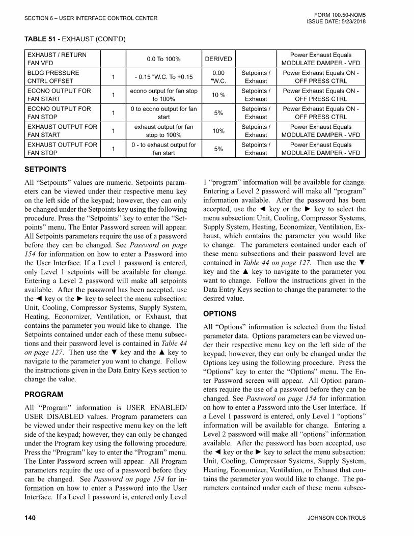
JOHNSON CONTROLS140
FORM 100.50-NOM5ISSUE DATE: 5/23/2018SECTION 6 – USER INTERFACE CONTROL CENTER
TABLE 51 - EXHAUST (CONT'D)
EXHAUST / RETURN FAN VFD
0.0 To 100% DERIVEDPower Exhaust Equals
MODULATE DAMPER - VFDBLDG PRESSURE CNTRL OFFSET
1 - 0.15 "W.C. To +0.150.00
"W.C.Setpoints / Exhaust
Power Exhaust Equals ON - OFF PRESS CTRL
ECONO OUTPUT FOR FAN START
1econo output for fan stop
to 100%10 %
Setpoints / Exhaust
Power Exhaust Equals ON - OFF PRESS CTRL
ECONO OUTPUT FOR FAN STOP
10 to econo output for fan
start5%
Setpoints / Exhaust
Power Exhaust Equals ON - OFF PRESS CTRL
EXHAUST OUTPUT FOR FAN START
1exhaust output for fan
stop to 100%10%
Setpoints / Exhaust
Power Exhaust Equals MODULATE DAMPER - VFD
EXHAUST OUTPUT FOR FAN STOP
10 - to exhaust output for
fan start5%
Setpoints / Exhaust
Power Exhaust Equals MODULATE DAMPER - VFD
SETPOINTSAll “Setpoints” values are numeric. Setpoints param-eters can be viewed under their respective menu key on the left side of the keypad; however, they can only be changed under the Setpoints key using the following procedure. Press the “Setpoints” key to enter the “Set-points” menu. The Enter Password screen will appear. All Setpoints parameters require the use of a password before they can be changed. See Password on page 154 for information on how to enter a Password into the User Interface. If a Level 1 password is entered, only Level 1 setpoints will be available for change. Entering a Level 2 password will make all setpoints available. After the password has been accepted, use the ◄ key or the ► key to select the menu subsection: Unit, Cooling, Compressor Systems, Supply System, Heating, Economizer, Ventilation, or Exhaust, that contains the parameter you would like to change. The Setpoints contained under each of these menu subsec-tions and their password level is contained in Table 44 on page 127. Then use the ▼ key and the ▲ key to navigate to the parameter you want to change. Follow the instructions given in the Data Entry Keys section to change the value.
PROGRAMAll “Program” information is USER ENABLED/USER DISABLED values. Program parameters can be viewed under their respective menu key on the left side of the keypad; however, they can only be changed under the Program key using the following procedure. Press the “Program” key to enter the “Program” menu. The Enter Password screen will appear. All Program parameters require the use of a password before they can be changed. See Password on page 154 for in-formation on how to enter a Password into the User Interface. If a Level 1 password is, entered only Level
1 “program” information will be available for change. Entering a Level 2 password will make all “program” information available. After the password has been accepted, use the ◄ key or the ► key to select the menu subsection: Unit, Cooling, Compressor Systems, Supply System, Heating, Economizer, Ventilation, Ex-haust, which contains the parameter you would like to change. The parameters contained under each of these menu subsections and their password level are contained in Table 44 on page 127. Then use the ▼ key and the ▲ key to navigate to the parameter you want to change. Follow the instructions given in the Data Entry Keys section to change the parameter to the desired value.
OPTIONSAll “Options” information is selected from the listed parameter data. Options parameters can be viewed un-der their respective menu key on the left side of the keypad; however, they can only be changed under the Options key using the following procedure. Press the “Options” key to enter the “Options” menu. The En-ter Password screen will appear. All Option param-eters require the use of a password before they can be changed. See Password on page 154 for information on how to enter a Password into the User Interface. If a Level 1 password is entered, only Level 1 “options” information will be available for change. Entering a Level 2 password will make all “options” information available. After the password has been accepted, use the ◄ key or the ► key to select the menu subsection: Unit, Cooling, Compressor Systems, Supply System, Heating, Economizer, Ventilation, or Exhaust that con-tains the parameter you would like to change. The pa-rameters contained under each of these menu subsec-

JOHNSON CONTROLS 141
SECTION 6 – USER INTERFACE CONTROL CENTERFORM 100.50-NOM5 ISSUE DATE: 5/23/2018
6
tions and their password level is contained in Table 44 on page 127. Then use the ▼ key and the ▲ key to navigate to the parameter you want to change. Follow the instructions given in the Data Entry Keys section to change the parameter to the desired value.
DATE / TIMETo change the day, time, and date press the DATE/TIME key. The ▼ key is used to scroll to the next item to be programmed and the ▲ key scrolls to the previ-ous item. The following messages will be displayed. The first line will be an active display and the second line will be the entry line.
CLOCK FRI 18 JUN 2004 10:15:33 AM DAY OF MONTH =XX
CLOCK FRI 18 JUN 2004 10:15:33 AM MONTH =XX
CLOCK FRI 18 JUN 2004 10:15:33 AM MINUTE =XX
CLOCK FRI 18 JUN 2004 10:15:33 AM12 HOUR PERIOD =XX
CLOCK FRI 18 JUN 2004 10:15:33 AM TIME FORMAT =XXXXXXX
CLOCK FRI 18 JUN 2001 10:15:33 AM POWER OFF TIME =XXXXX
CLOCK FRI 18 JUN 2004 10:15:33 AMDAY OF WEEK =XXX
CLOCK FRI 18 JUN 2004 10:15:33 AM YEAR =XXXX
CLOCK FRI 18 JUN 2004 10:15:33 AM HOUR =XX
Follow the instructions given in the Data Entry Keys section to change the above values.
SCHEDULE
The “clock schedule” function can be USER EN-ABLED / USER DISABLED by using the schedule screen below.
To set the schedule, press the SCHEDULE key. The display will show the following message:
SCHEDULE MON TO EDIT+START =06:00 AM STOP =10:00 PM
SCHEDULE TUE TO EDIT START =06:00 AM STOP =10:00 PM
SCHEDULE WED TO EDIT START =06:00 AM STOP =10:00 PM
SCHEDULE THU TO EDIT START =06:00 AM STOP =10:00 PM
SCHEDULE TO EDITOCCUPANCY SCHEDULE USER ENABLED
SCHEDULE FRI TO EDIT START =06:00 AM STOP =10:00 PM
SCHEDULE SAT TO EDIT START =06:00 AM STOP =10:00 PM
SCHEDULE SUN TO EDIT START =06:00 AM STOP =10:00 PM
To change the start or stop time, press the key. The line under the 0 is the cursor. If the start time is wrong, it may be changed from the numeric keypad. Once the correct value (hour and minute) is entered, press the key. The cursor will then move to the AM/PM se-lection. This value may be chosen by the +/- key and entered by pressing the key. This process may be followed until the hour, minutes, and meridian of both the START and STOP points are set. Press the ▼ key to get the schedule for the next day to appear. The start and stop time of each day may be programmed differ-ently. If you want to view the schedule without making a change, simply press the ▼ key until the day you wish to view appears. The ▲ key will scroll backwards to the previous screen.

JOHNSON CONTROLS142
FORM 100.50-NOM5ISSUE DATE: 5/23/2018SECTION 6 – USER INTERFACE CONTROL CENTER
After the SUN (Sunday) schedule appears on the dis-play a subsequent press of the ▼ key will display the Holiday schedule. This is a two-part display. The first reads:
SCHEDULE HOL START =06:00 AM STOP =10:00 PM
The times may be set using the same procedure as de-scribed above for the days of the week.
Continue pressing the ▼ key to set the 15 holiday dates. The display will read:
SCHEDULE MMDD HOLIDAY 01 = 1225
The month and the day of each holiday are entered in this format. Enter 0000 to not specify a holiday. The MMDD is displayed when the value is being edited to remind the operator what the format of this number is. E.g. 1225 represents December 25.
The line below the empty space is the cursor and will move to the next or previous empty space when the ◄ key or the ► key is pressed. To set the Holiday, the cursor is moved to the space following the day of the week of the holiday and the +/- key is pressed. An * will appear in the space signifying that day as a holi-day. The Holiday schedule must be programmed week-ly. If there is no holiday, the +/- key is used to delete the *. The key is used to accept the holiday schedule for the next seven days.
OPERATING HOURS / START COUNTERCompressor Operating hours and Compressor Starts; Supply Fan Operating hours and Supply Fan starts; Ex-haust Fan operating hours and Exhaust Fan starts; and Return Fan operating hours and Return Fan starts are displayed via one key press. The maximum value for both hours and starts is 99,999, at which point they will roll over to 0. Following are the displays.
TABLE 52 - OPERATING HOURS / START COUNTER
DISPLAY TEXTPASSWORDLEVEL
RANGE DEFAULTSETTING
LOCATIONSHOW WHEN
COMPRESSOR 1A OPER HRSCOMPRESSOR 1A STARTS
1 DERIVED
COMPRESSOR 1B OPER HRSCOMPRESSOR 1B STARTS
1 DERIVED
COMPRESSOR 2A OPER HRSCOMPRESSOR 2A STARTS
1 DERIVED
COMPRESSOR 2B OPER HRSCOMPRESSOR 2B STARTS
1 DERIVED
CONDENSER FAN 1A
CONDENSER FAN 1B
CONDENSER FAN 2A
CONDENSER FAN 2B
EXHAUST FAN OPER HRSEXHAUST FAN STARTS
1 DERIVEDPOWER EXHAUST ON/OFF DMPR / ON/
OFF PRESS / MODULATE DAMPER - VFD.
SUPPLY FAN OPER HRSSUPPLY FAN STARTS
1 DERIVED
RETURN FAN OPER HRSRETURN FAN STARTS
1 DERIVEDSupply System Type Equals Return Fan
W/EXH RETURN W/O EXHAUST.

JOHNSON CONTROLS 143
SECTION 6 – USER INTERFACE CONTROL CENTERFORM 100.50-NOM5 ISSUE DATE: 5/23/2018
6
Shown below is a typical screen example.
HOURS / STARTS oper HRS. xxxxx COMPRESSOR 1A Starts xxxxx
PRINTThe PRINT function is not available. In order to view operating data, refer to SECTION 8 – SERVICE for in-formation on how to use a MULTI-MEDIA CARD to record operating data.
SERVICETo enter Service Mode, press the SERVICE key. The following message is the initial screen and is displayed when the SERVICE key is pressed, unless a Level 2 password is active.
SERVICEENTER PASSWORD
All the DIGITAL outputs (DO) except for the compres-sors can be forced ON. In order to force the outputs the LOCAL STOP switch must be in the OFF position. To force an output ON use the ◄ or ► key to navigate to the SERVICE DO section. Then use the ▲ or ▼ key to select the output you want to force ON. Press the key and then use the ► key to switch it from OFF to ON. Press the key again to energize the output. Repeat the above process in reverse to turn the forced output back to OFF.
All the ANALOG outputs (AO) can be forced ON. In order to force the outputs the LOCAL STOP switch must be in the OFF position. To force an output ON use the ◄ or ► key to navigate to the SERVICE AO section. Then use the ▲ or ▼ key to select the output you want to force ON. Press the key and then use the numeric key pad to enter the output value. Press the key again to energize the output. Repeat the above process in reverse to turn the forced output back to 0.0. Failure to do so will leave the forced output value in place until a different value is initiated by the operation of the unit.
The ► key can be used to jump to the beginning of the next section of displays and the ◄ key can be used to jump to the beginning of the previous section of dis-plays. The sections of displays are as follows:
• Parameters
• Analog Inputs
• Digital Inputs
• Digital Outputs
• Analog Outputs
The attached Table 53 on page 143 lists the Displayed Text, Input or Output type, Unit Control terminal loca-tion (ID), Value Range, and when item is displayed.
TABLE 53 - SERVICEDISPLAY TEXT TYPE ID VALUE RANGE LOCATION DESCRIPTION
DATA LOG FORMAT OFF USED TO ACTIVATE THE DATA LOG
FEATURE OF THE CONTROL
DATA LOG ERROR
ERROR DETAIL
SEE Table 68 on
page 195
DATA LOG ERROR DETAIL(ONLY DISPLAYED WHEN ERROR IS
PRESENT)
ERROR STATE
SEE Table 67 on page 193
DATA LOG ERROR STATE(ONLY DISPLAYED WHEN ERROR IS
PRESENT)
UPDATE FLASH ON / OFFUSED TO UPDATE CONTROL
SOFTWARE
UPDATE FLASH ERROR
DESCRIPTION OF THE ERROR(ONLY DISPLAYED WHEN ERROR IS
PRESENT)FACTORY RUN
TESTERUSER DISABLE / USER ENABLE
ONLY USED FOR FACTORY RUN TEST
COMPRESSOR 1ADIGITAL OUTPUT
TB5-2 ON / OFF I/O BOARDSTATUS OF THE DIGITAL OUTPUT
TO COMPRESSOR 1A

JOHNSON CONTROLS144
FORM 100.50-NOM5ISSUE DATE: 5/23/2018SECTION 6 – USER INTERFACE CONTROL CENTER
DISPLAY TEXT TYPE ID VALUE RANGE LOCATION DESCRIPTION
COMPRESSOR 1BDIGITAL OUTPUT
TB5-4 ON / OFF I/O BOARDSTATUS OF THE DIGITAL OUTPUT
TO COMPRESSOR 1B
COMPRESSOR 2ADIGITAL OUTPUT
TB5-6 ON / OFF I/O BOARDSTATUS OF THE DIGITAL OUTPUT
TO COMPRESSOR 2A
COMPRESSOR 2BDIGITAL OUTPUT
TB5-8 ON / OFF I/O BOARDSTATUS OF THE DIGITAL OUTPUT
TO COMPRESSOR 2B
CONDENSER FAN 1A/1DIGITAL OUTPUT
TB3-7 ON / OFF I/O BOARDSTATUS OF DIGITAL OUTPUT TO
CONDENSER FAN 1A
CONDENSER FAN 1B/2DIGITAL OUTPUT
TB3-8 ON / OFF I/O BOARDSTATUS OF DIGITAL OUTPUT TO
CONDENSER FAN 1B
CONDENSER FAN 2A/3DIGITAL OUTPUT
TB3-9 ON / OFF I/O BOARDSTATUS OF DIGITAL OUTPUT TO
CONDENSER FAN 2A
CONDENSER FAN 2B/4DIGITAL OUTPUT
TB3-10 ON / OFF I/O BOARDSTATUS OF DIGITAL OUTPUT TO
CONDENSER FAN 2B
ELECTRIC HEAT STG 1DIGITAL OUTPUT
TB4-2 ON / OFF I/O BOARDSTATUS OF ELECTRIC HEAT
DIGITAL OUTPUT TO STAGE 1
ELECTRIC HEAT STG 2DIGITAL OUTPUT
TB4-3 ON / OFF I/O BOARDSTATUS OF ELECTRIC HEAT
DIGITAL OUTPUT TO STAGE 2
ELECTRIC HEAT STG 3DIGITAL OUTPUT
TB4-4 ON / OFF I/O BOARDSTATUS OF ELECTRIC HEAT
DIGITAL OUTPUT TO STAGE 3
ELECTRIC HEAT STG 4DIGITAL OUTPUT
TB4-5 ON / OFF I/O BOARDSTATUS OF ELECTRIC HEAT
DIGITAL OUTPUT TO STAGE 4
ELECTRIC HEAT STG 5DIGITAL OUTPUT
TB4-7 ON / OFF I/O BOARDSTATUS OF ELECTRIC HEAT
DIGITAL OUTPUT TO STAGE 5
ELECTRIC HEAT STG 6DIGITAL OUTPUT
TB4-8 ON / OFF I/O BOARDSTATUS OF ELECTRIC HEAT
DIGITAL OUTPUT TO STAGE 6
ELECTRIC HEAT STG 7DIGITAL OUTPUT
TB4-9 ON / OFF I/O BOARDSTATUS OF ELECTRIC HEAT
DIGITAL OUTPUT TO STAGE 7STG GAS
FURN 1 LOWDIGITAL OUTPUT
TB4-2 ON / OFF I/O BOARDSTATUS OF STAGED GAS HEAT
DIGITAL OUTPUT TO STAGE 1 LOW
STG GASFURN 1 HIGH
DIGITAL OUTPUT
TB4-3 ON / OFF I/O BOARDSTATUS OF STAGED GAS HEAT DIGITAL OUTPUT TO STAGE 1
HIGHSTG GAS
FURN 2 LOWDIGITAL OUTPUT
TB4-4 ON / OFF I/O BOARDSTATUS OF STAGED GAS HEAT
DIGITAL OUTPUT TO STAGE 2 LOW
STG GASFURN 2 HIGH
DIGITAL OUTPUT
TB4-5 ON / OFF I/O BOARDSTATUS OF STAGED GAS HEAT DIGITAL OUTPUT TO STAGE 2
HIGHSTG GAS
FURN 3 LOWDIGITAL OUTPUT
TB4-7 ON / OFF I/O BOARDSTATUS OF STAGED GAS HEAT
DIGITAL OUTPUT TO STAGE 3 LOW
STG GASFURN 3 HIGH
DIGITAL OUTPUT
TB4-8 ON / OFF I/O BOARDSTATUS OF STAGED GAS HEAT DIGITAL OUTPUT TO STAGE 3
HIGH
MOD GASFURN 1A LOW
DIGITAL OUTPUT
TB4-2 ON / OFF I/O BOARDSTATUS OF MOD GAS HEAT
DIGITAL OUTPUT TO STAGE 1A LOW
MOD GASFURN 1A HI
DIGITAL OUTPUT
TB4-3 ON / OFF I/O BOARDSTATUS OF MOD GAS HEAT
DIGITAL OUTPUT TO STAGE 1A HIGH
TABLE 53 - SERVICE (CONT'D)

JOHNSON CONTROLS 145
SECTION 6 – USER INTERFACE CONTROL CENTERFORM 100.50-NOM5 ISSUE DATE: 5/23/2018
6
DISPLAY TEXT TYPE ID VALUE RANGE LOCATION DESCRIPTIONMOD GAS
FURN 2 LOWDIGITAL OUTPUT
TB4-4 ON / OFF I/O BOARDSTATUS OF MOD GAS HEAT
DIGITAL OUTPUT TO STAGE 2 LOW
MOD GASFURN 2 HIGH
DIGITAL OUTPUT
TB4-5 ON / OFF I/O BOARDSTATUS OF MOD GAS HEAT
DIGITAL OUTPUT TO STAGE 2 HIGH
MOD GASFURN 3 LOW
DIGITAL OUTPUT
TB4-7 ON / OFF I/O BOARDSTATUS OF MOD GAS HEAT
DIGITAL OUTPUT TO STAGE 3 LOW
MOD GASFURN 3 HIGH
DIGITAL OUTPUT
TB4-8 ON / OFF I/O BOARDSTATUS OF MOD GAS HEAT
DIGITAL OUTPUT TO STAGE 3 HIGH
MOD GASFURN 1B
DIGITAL OUTPUT
TB4-9 ON / OFF I/O BOARDSTATUS OF MOD GAS HEAT
DIGITAL OUTPUT TO STAGE 1B
SUPPLY FANOUTPUT (CV)
DIGITAL OUTPUT
TB6-2 ON / OFF ALWAYSSTATUS OF SUPPLY FAN DIGITAL OUTPUT ON CONSTANT VOLUME
UNITSEXHAUST FAN OUTPUT (CV)
DIGITAL OUTPUT
TB6-3 ON / OFF I/O BOARDSTATUS OF EXHAUST FAN DIGITAL
OUTPUT ON CV UNITS
VAV HEAT RELAYDIGITAL OUTPUT
TB1-12 ON / OFF I/O BOARDSTATUS OF THE DIGITAL OUTPUT
FOR THE VAV HEAT RELAY
FAN FAULTDIGITAL OUTPUT
TB1-6OKAY /
FAULTEDI/O BOARD
DIGITAL OUTPUT THAT IS GENERATED WHEN THERE IS A
SUPPLY FAN FAULT
COOL/HEATING FAULTDIGITAL OUTPUT
TB1-8 ON / OFF I/O BOARDDIGITAL OUTPUT THAT IS
GENERATED WHEN THERE IS A COOLING/HEATING FAULT
SENSOR/MISC FAULTDIGITAL OUTPUT
TB1-10 ON / OFF I/O BOARDDIGITAL OUTPUT THAT IS
GENERATED WHEN THERE IS A SENSOR/MISC FAULT
VAV SUPPLY FAN START
DIGITAL OUTPUT
TB1-2 ON / OFF I/O BOARDRUN SIGNAL TO VFD FOR SUPPLY
FAN STARTVAV EXHAUST FAN
STARTDIGITAL OUTPUT
TB1-4 ON / OFF I/O BOARDRUN SIGNAL TO VFD FOR
EXHAUST/RETURN FAN STARTSUPPLY FAN VFD
SPEEDANALOG OUTPUT
TB9-10-10 VDC
I/O BOARDANALOG OUTPUT TO THE SUPPLY
FAN VFD
EXHAUST DAMPER POSITION
ANALOG OUTPUT
TB9-70-10VDC
I/O BOARDANALOG OUTPUT TO THE
EXHAUST DAMPER
EXHAUST / RETURN FAN VFD
ANALOG OUTPUT
TB9-30-10VDC
I/O BOARDANALOG OUTPUT TO THE
EXHAUST OR RETURN FAN VFD
OA DAMPER POSITIONANALOG OUTPUT
TB9-50-10VDC
I/O BOARDANALOG OUTPUT TO THE ECONOMIZER DAMPERS
HEATING VALVEANALOG OUTPUT
TB9-90-10VDC
I/O BOARDANALOG OUTPUT TO THE
HEATING VALVE
BYPASS DAMPER POSITION
ANALOG OUTPUT
TB9-11 0-10 VDC I/O BOARDANALOG OUTPUT TO THE
FLEXSYS BYPASS DAMPERSUPPLY AIR TEMP
CURRENTANALOG
INPUTJ1-1 0-5 VOLTS I/O BOARD
ANALOG INPUT FROM THE SUPPLY OR MIXED AIR SENSOR
MX SUPPLY AIR TEMP CURRENT
ANALOG INPUT
J1-1 0-5 VOLTS I/O BOARDANALOG INPUT FROM THE
SUPPLY OR MIXED AIR SENSOR
TABLE 53 - SERVICE (CONT'D)

JOHNSON CONTROLS146
FORM 100.50-NOM5ISSUE DATE: 5/23/2018SECTION 6 – USER INTERFACE CONTROL CENTER
DISPLAY TEXT TYPE ID VALUE RANGE LOCATION DESCRIPTION
HEAT EXCHANGER TEMP
ANALOG INPUT
J1-2 0-5 VOLTS I/O BOARD
ANALOG INPUT FROM THE TEMPERATURE SENSOR
POSITIONED BEFORE THE HEAT SECTION
FLEX EVAP TEMP CURRENT
ANALOG INPUT
J1-3 0-5 VOLTS I/O BOARD
ANALOG INPUT FROM THE TEMPERATURE SENSORS
POSITIONED ON THE LEAVING SIDE OF THE EVAPORATOR COIL
OUTSIDE AIR TEMPANALOG
INPUTJ2-1 0-5 VOLTS I/O BOARD
ANALOG INPUT FROM THE OUTDOOR AIR TEMPERATURE
SENSOR
RETURN AIR TEMP CURRENT
ANALOG INPUT
J2-2 0-5 VOLTS I/O BOARDANALOG INPUT FROM THE
RETURN AIR TEMPERATURE SENSOR
OUTSIDE AIR HUMIDITY
ANALOG INPUT
J2-3 0-5 VOLTS I/O BOARDANALOG INPUT FROM THE
OUTDOOR AIR HUMIDITY SENSORRETURN AIR
HUMIDITYANALOG
INPUTJ2-4 0-5 VOLTS I/O BOARD
ANALOG INPUT FROM THE RETURN AIR HUMIDITY SENSOR
TEMPERATURE SUCTION 1
ANALOG INPUT
J3-1 0-5 VOLTS I/O BOARDANALOG INPUT FROM THE SYSTEM 1 SUCTION LINE TEMPERATURE SENSOR
TEMPERATURE SUCTION 2
ANALOG INPUT
J3-2 0-5 VOLTS I/O BOARDANALOG INPUT FROM THE SYSTEM 2 SUCTION LINE TEMPERATURE SENSOR
TEMPERATURE SUCTION 3
ANALOG INPUT
J3-3 0-5 VOLTS I/O BOARDANALOG INPUT FROM THE SYSTEM 3 SUCTION LINE TEMPERATURE SENSOR
PRESSURE SUCTION 1
ANALOG INPUT
J3-4 0-5 VOLTS I/O BOARDANALOG INPUT FROM THE
SYSTEM 1 SUCTION PRESSURE TRANSDUCER
PRESSURE SUCTION 2
ANALOG INPUT
J4-1 0-5 VOLTS I/O BOARDANALOG INPUT FROM THE
SYSTEM 2 SUCTION PRESSURE TRANSDUCER
PRESSURE SUCTION 3
ANALOG INPUT
J4-2 0-5 VOLTS I/O BOARDANALOG INPUT FROM THE
SYSTEM 3 SUCTION PRESSURE TRANSDUCER
PRESSURE DISCHARGE 1
ANALOG INPUT
J4-3 0-5 VOLTS I/O BOARDANALOG INPUT FROM THE
SYSTEM 1 DISCHARGE PRESSURE TRANSDUCER
PRESSURE DISCHARGE 2
ANALOG INPUT
J4-4 0-5 VOLTS I/O BOARDANALOG INPUT FROM THE
SYSTEM 2 DISCHARGE PRESSURE TRANSDUCER
PRESSURE DISCHARGE 3
ANALOG INPUT
J4-5 0-5 VOLTS I/O BOARDANALOG INPUT FROM THE
SYSTEM 3 DISCHARGE PRESSURE TRANSDUCER
CO2 LEVEL OUTSIDEANALOG
INPUTJ5-2 0-5 VOLTS I/O BOARD
ANALOG INPUT OF THE OUTDOOR CO2 SENSOR
CO2 LEVEL INSIDEANALOG
INPUTJ5-3 0-5 VOLTS I/O BOARD
ANALOG INPUT FROM THE INDOOR CO2 SENSOR
TABLE 53 - SERVICE (CONT'D)

JOHNSON CONTROLS 147
SECTION 6 – USER INTERFACE CONTROL CENTERFORM 100.50-NOM5 ISSUE DATE: 5/23/2018
6
TABLE 53 - SERVICE (CONT'D)DISPLAY TEXT TYPE ID VALUE RANGE LOCATION DESCRIPTION
RETURN FAN PRESS CURRENT
ANALOG INPUT
J6-1 0-5 VOLTS I/O BOARDANALOG INPUT FROM THE RETURN FAN PRESSURE
TRANSDUCER
DUCT STATIC PRESS CURRENT
ANALOG INPUT
J6-2 0-5 VOLTS I/O BOARDANALOG INPUT FROM THE
SUPPLY AIR PRESSURE TRANSDUCER
BUILDING PRESSURE CURRENT
ANALOG INPUT
J6-3 0-5 VOLTS I/O BOARDANALOG INPUT FROM
THE BUILDING PRESSURE TRANSDUCER
OA FLOW INPUT 1ANALOG
INPUTJ6-4
0 TO 4095 A/D COUNTS (1-5
VOLTS)I/O BOARD
THIS IS THE AIR FLOW INPUT FROM THE TEK AIR MEASURING
STATION
OA FLOW INPUT 2ANALOG
INPUTJ6-5
0 TO 4095 A/D COUNTS (1-5
VOLTS)I/O BOARD
THIS IS THE AIR FLOW INPUT FROM THE TEK AIR MEASURING
STATION
ZONE TEMP CURRENTANALOG
INPUTJ7-1 0-5 VOLTS I/O BOARD
ANALOG INPUT FROM THE ZONE TEMPERATURE SENSOR
UNDERFLOOR SLAB TEMP
ANALOG INPUT
J7-2 0-5 VOLTS I/O BOARDANALOG INPUT FROM THE UNDER FLOOR TEMPERATURE SENSOR
UNDERFLOOR AIR HUMIDITY
ANALOG INPUT
J7-3 0-5 VOLTS I/O BOARDANALOG INPUT FROM THE
UNDERFLOOR HUMIDITY SENSOR
SUPPLY AIRTEMP RST
ANALOG INPUT
J7-4 0-5 VOLTS I/O BOARDHARDWIRED ANALOG INPUT TO RESET THE SUPPLY AIR TEMPERATURE SETPOINT
DUCT STATIC PRES RESET
ANALOG INPUT
J7-5 0-5 VOLTS I/O BOARDHARDWIRED ANALOG INPUT TO RESET THE DUCT STATIC
PRESSURE SETPOINT
FURNACE STATUSANALOG
INPUTJ5-1 0-5 VOLTS I/O BOARD
ANALOG INPUT OF THE FURNACE MULTIPLEXER
FURNACE STATUS COUNTS
ANALOG INPUT
J5-1 0 - 4095 I/O BOARDSTATUS OF THE INPUT FROM THE FURNACE MULTIPLEXER BOARD
IN COUNT
FURNACE 1A STAT HI
DIGITAL INPUT
TB01-3 ON / OFFFURNACE
MULTIPLEXER
FURNACE 1A HZ STATUS INPUT TO FURNACE MULTIPLEXER
BOARD
FURNACE 1 STATUSDIGITAL INPUT
TB01-2 ON / OFFFURNACE
MULTIPLEXERFURNACE 1 STATUS INPUT TO
FURNACE MULTIPLEXER BOARD
FURNACE 1A STATUSDIGITAL INPUT
TB01-2 ON / OFFFURNACE
MULTIPLEXERFURNACE 1A STATUS INPUT TO
FURNACE MULTIPLEXER BOARD
FURNACE 1B STATUSDIGITAL INPUT
TB01-6 ON / OFFFURNACE
MULTIPLEXERFURNACE 1B STATUS INPUT TO FURNACE MULTIPLEXER BOARD
FURNACE 2 STATUSDIGITAL INPUT
TB01-3 ON / OFFFURNACE
MULTIPLEXERFURNACE 2 STATUS INPUT TO
FURNACE MULTIPLEXER BOARD
FURNACE 3 STATUSDIGITAL INPUT
TB01-4 ON / OFFFURNACE
MULTIPLEXERFURNACE 3 STATUS INPUT TO
FURNACE MULTIPLEXER BOARD
OCCUPANCY STATEDIGITAL INPUT
TB8-2OCCUPIED /
UNOCCUPIEDI/O BOARD
HARDWIRED DIGITAL INPUT TO PUT THE UNIT INTO THE
OCCUPIED MODE
LOCAL STOPDIGITAL INPUT
TB8-1 RUN / STOP I/O BOARDDIGITAL INPUT THAT TURNS THE
UNIT ON AND OFF

JOHNSON CONTROLS148
FORM 100.50-NOM5ISSUE DATE: 5/23/2018SECTION 6 – USER INTERFACE CONTROL CENTER
TABLE 53 - SERVICE (CONT'D)
DISPLAY TEXT TYPE ID VALUE RANGE LOCATION DESCRIPTION
FAN (G)DIGITAL INPUT
TB8-8 ON / OFF I/O BOARDHARDWIRED DIGITAL INPUT TO TURN THE SUPPLY FAN ON AND
OFF
Y1 LOW COOLDIGITAL INPUT
TB8-10 ON / OFF I/O BOARDHARDWIRED DIGITAL INPUT TO
PLACE THE UNIT IN FIRST STAGE COOLING MODE
Y2 HIGH COOLDIGITAL INPUT
TB8-11 ON / OFF I/O BOARDHARDWIRED DIGITAL INPUT TO
PLACE THE UNIT IN SECOND STAGE COOLING MODE
W1 LOW HEATDIGITAL INPUT
TB8-13 ON / OFF I/O BOARDHARDWIRED DIGITAL INPUT TO
PLACE THE UNIT IN FIRST STAGE HEATING MODE
W2 HIGH HEATDIGITAL INPUT
TB8-14 ON / OFF I/O BOARDHARDWIRED DIGITAL INPUT TO
PLACE THE UNIT IN SECOND STAGE HEATING MODE
SAFETY INPUT CHAIN 1
DIGITAL INPUT
TB7-1OKAY /
FAULTEDI/O BOARD
DIGITAL INPUT FROM THE COMPRESSOR SYSTEM 1 SAFETY
CIRCUIT
SAFETY INPUT CHAIN 2
DIGITAL INPUT
TB7-2OKAY /
FAULTEDI/O BOARD
DIGITAL INPUT FROM THE COMPRESSOR SYSTEM 2 SAFETY
CIRCUIT
SAFETY INPUT CHAIN 3
DIGITAL INPUT
TB7-4OKAY /
FAULTEDI/O BOARD
DIGITAL INPUT FROM THE COMPRESSOR SYSTEM 3 SAFETY
CIRCUIT
SAFETY INPUTS LPCO 1
DIGITAL INPUT
TB7-5OKAY /
FAULTEDI/O BOARD
DIGITAL INPUT FROM THE COMPRESSOR SYSTEM 1 LOW PRESSURE SAFETY CIRCUIT
SAFETY INPUTS LPCO 2
DIGITAL INPUT
TB7-7OKAY /
FAULTEDI/O BOARD
DIGITAL INPUT FROM THE COMPRESSOR SYSTEM 2 LOW PRESSURE SAFETY CIRCUIT
SUPPLY FAN OUTPUTDIGITAL INPUT
TB7-11RUNNING / STOPPED
I/O BOARDDIGITAL INPUT FOR THE SUPPLY FAN RUN VERIFICATION CIRCUIT
EXHAUST FAN STATUSDIGITAL INPUT
TB7-11RUNNING / STOPPED
I/O BOARDDIGITAL INPUT FROM THE
EXHAUST FAN RUN VERIFICATION CIRCUIT
RETURN FAN STATUSDIGITAL INPUT
TB7-11RUNNING / STOPPED
I/O BOARDDIGITAL INPUT FROM THE
RETURN FAN RUN VERIFICATION CIRCUIT
FILTER STATUSDIGITAL INPUT
TB7-13 OKAY / CHANGE I/O BOARDDIGITAL INPUT FROM THE DIRTY
FILTER PRESSURE SWITCHHW/STEAMFRZ STAT
DIGITAL INPUT
TB7-14OKAY /
FAULTEDI/O BOARD
DIGITAL INPUT FROM THE HOT WATER FREEZESTAT
SMOKE PURGE 1DIGITAL INPUT
TB8-4 ON / OFF I/O BOARDHARDWIRED DIGITAL INPUT
TO PLACE THE UNIT IS SMOKE PURGE 1 MODE
SMOKE PURGE 2DIGITAL INPUT
TB8-5 ON / OFF I/O BOARDHARDWIRED DIGITAL INPUT
TO PLACE THE UNIT IS SMOKE PURGE 2 MODE

JOHNSON CONTROLS 149
SECTION 6 – USER INTERFACE CONTROL CENTERFORM 100.50-NOM5 ISSUE DATE: 5/23/2018
6
TABLE 53 - SERVICE (CONT'D)
DISPLAY TEXT TYPE ID VALUE RANGE LOCATION DESCRIPTION
SMOKE PURGE 3DIGITAL INPUT
TB8-7 ON / OFF I/O BOARDHARDWIRED DIGITAL INPUT
TO PLACE THE UNIT IS SMOKE PURGE 3 MODE
DUCT PRES RESET BAS
COMMUNPORT
P1USER DISABLE / USER ENABLE
IPU BOARD
THIS ITEM MUST BE ENABLED IN ORDER TO COMMUNICATE A
DUCT STATIC PRESSURE RESET VALUE TO THE UNIT
DUCT STATIC PRES RESET BAS
COMMUNPORT
P10 TO 100% IPU BOARD
THE DUCT STATIC RESET VALUE BEING COMMUNICATED TO THE
UNIT THROUGH THE BAS SYSTEM
EXHAUST CONTROL BAS
COMMUNPORT
P1ENABLE/DISABLE
IPU BOARD
ENABLES OR DISABLES CONTROL OF THE EXHAUST FAN OR
MODULATING EXHAUST DAMPER (RETURN FAN)
EXHAUST DAMPER/VFD
COMMUNPORT
P10 TO 100% IPU BOARD
COMMUNICATED SIGNAL TO SET THE POSITION OF THE MODULAT-ING DAMPER (RETURN FAN) OR SPEED OF THE EXHAUST FAN.
FAN (G) BAS COMMUNPORT
P1ON / OFF IPU BOARD
GIVES THE STATUS OF THE COMMUNICATED FAN G INPUT
MORNING WARM UP CMD
COMMUNPORT
P1ON / OFF IPU BOARD
GIVES THE STATUS OF THE COMMUNICATED MORNING WARM
UP COMMAND
OCCUPANCY COMMAND
COMMUNPORT
P1OCCUPIED /
UNOCCUPIEDIPU BOARD
GIVES THE STATUS OF THE COMMUNICATED OCCUPANCY
COMMAND
SMOKE PURGE 1 BAS COMMUNPORT
P1ON OFF IPU BOARD
GIVES THE STATUS OF THE COMMUNICATED SMOKE PURGE 1
COMMAND
SMOKE PURGE 2 BAS COMMUNPORT
P1ON OFF IPU BOARD
GIVES THE STATUS OF THE COMMUNICATED SMOKE PURGE 2
COMMAND
SMOKE PURGE 3 BAS COMMUNPORT
P1ON OFF IPU BOARD
GIVES THE STATUS OF THE COMMUNICATED SMOKE PURGE 3
COMMAND
SAT RESET BAS COMMUNPORT
P1USER DISABLE / USER ENABLE
IPU BOARD
THIS ITEM MUST BE ENABLED IN ORDER TO COMMUNICATE A SUPPLY AIR TEMPERATURE RESET VALUE TO THE UNIT
SUPPLY AIR TEMP RESET BAS
COMMUNPORT
P10 TO 5 VOLTS IPU BOARD
THE SUPPLY AIR TEMPERATURE RESET VALUE BEING
COMMUNICATED TO THE UNIT THROUGH THE BAS SYSTEM

JOHNSON CONTROLS150
FORM 100.50-NOM5ISSUE DATE: 5/23/2018SECTION 6 – USER INTERFACE CONTROL CENTER
TABLE 53 - SERVICE (CONT'D)
DISPLAY TEXT TYPE ID VALUE RANGE LOCATION DESCRIPTION
SYSTEM STOP COMMUNPORT
P1
0 - ALLOWS ALL COMPRESSORS
TO OPERATE; 1 - TURNS OFF COMPRESSOR
SYSTEM 1; 2 - TURNS OFF
COMPRESSOR SYSTEM 2; 3 - TURNS OFF
COMPRESSOR SYSTEM 3
IPU BOARDGIVES THE STATUS OF THE
COMMUNICATED SYSTEM STOP COMMAND
UNDER FLR HUMI BAS COMMUNPORT
P1USER DISABLE / USER ENABLE
IPU BOARD
THIS ITEM MUST BE ENABLED IN ORDER TO COMMUNICATE A
UNDER FLOOR HUMIDITY VALUE TO THE UNIT
UNDRFLOOR AIR HUMIDITY BAS
COMMUNPORT
P10 TO 100% IPU BOARD
THE UNDER FLOOR HUMIDITY VALUE BEING COMMUNICATED TO
THE UNIT
UNDR FLR TEMP BAS COMMUNPORT
P1USER DISABLE / USER ENABLE
IPU BOARD
THIS ITEM MUST BE ENABLED IN ORDER TO COMMUNICATE AN UNDER FLOOR TEMPERATURE
VALUE TO THE UNIT
UNDERFLOOR SLAB TEMP BAS
COMMUNPORT
P1-20 °F TO 180 °F IPU BOARD
THIS IS THE ACTUAL UNDER FLOOR TEMPERATURE VALUE
BEING COMMUNICATED BY THE BAS SYSTEM
UNIT STOP COMMUNPORT
P1ON / OFF IPU BOARD
GIVES THE STATUS OF THE COMMUNICATED UNIT STOP
COMMAND
W1 LOW HEAT BAS COMMUNPORT
P1ON / OFF IPU BOARD
GIVES THE STATUS OF THE COMMUNICATED W1 LOW HEAT
COMMAND
W2 HIGH HEAT BAS COMMUNPORT
P1ON / OFF IPU BOARD
GIVES THE STATUS OF THE COMMUNICATED W2 HIGH HEAT
COMMAND
Y1 LOW COOL BAS COMMUNPORT
P1ON / OFF IPU BOARD
GIVES THE STATUS OF THE COMMUNICATED Y1 LOW COOL
COMMAND
Y2 HIGH COOL BAS COMMUNPORT
P1ON / OFF IPU BOARD
GIVES THE STATUS OF THE COMMUNICATED Y2 HIGH COOL
COMMAND
ZONE TEMP BAS COMMUNPORT
P1-20 °F TO 180 °F IPU BOARD
GIVES THE ACTUAL VALUE OF THE COMMUNICATED ZONE
TEMPERATURE
FIRMWARE CRC DERIVED 0 TO 99999 ALWAYSTHIS IS THE SIZE OF THE CODE IN THE SOFTWARE AND IS NOT FOR
FIELD USE

JOHNSON CONTROLS 151
SECTION 6 – USER INTERFACE CONTROL CENTERFORM 100.50-NOM5 ISSUE DATE: 5/23/2018
6
TABLE 53 - SERVICE (CONT'D)
DISPLAY TEXT TYPE ID VALUE RANGE LOCATION DESCRIPTION
REAL TIME UI - PEAK 5 SEC AND AVERAGE
DERIVED
THE AVERAGE AND PEAK OVER THE LAST 5 SECONDS TIME USED BY THE USER INTERFACE. THIS
IS NOT FOR FIELD USE
REAL TIME UI - LOST AND PEAK
DERIVEDTHE LOST AND PEAK TIME USED BY THE USER INTERFACE. THIS
IS NOT FOR FIELD USE
REAL TIME CONTROL - PEAK 5 SEC AND
AVERAGEDERIVED
THE AVERAGE AND PEAK OVER THE LAST 5 SECONDS TIME USED BY THE CONTROL. THIS IS NOT
FOR FIELD USE
REAL TIME CONTROL - LOST AND PEAK
DERIVEDTHE LOST AND PEAK TIME USED BY THE CONTROL. THIS IS NOT
FOR FIELD USE
DE MODIFIER ADDRESS
-1 TO 41943USED TO ENTER A SPECIFIC DE
INSTANCE. SEE COMMUNICATION ON PAGE 155
DE MODIFIER OFFSET -1 TO 99
USED IN COMBINATION WITH THE DE MODIFIER ADDRESS TO ENTER
A SPECIFIC DE INSTANCE. SEE COMMUNICATION ON PAGE 155
P1 BAUD RATE
1200,4800,
9600, 19200, 38400, 76800
ESTABLISHES THE COMMUNICATION BAUD RATE
FOR PORT 1
P1 MANUAL MAC ADDRESS
-1 TO 127
ALLOWS THE MANUAL ENTRANCE OF THE MAC ADDRESS FOR PORT 1. SEE COMMUNICATION ON PAGE
155
P1 PARITYNONE, EVEN, ODD, IGNORE
DO NOT CHANGE FROM DEFAULT VALUE FOR BACnet
P1 PROTOCOL BACnet, API KEEP SETTING ON BACnet
P1 STOP BITS 1-2DO NOT CHANGE FROM DEFAULT
VALUE FOR BACnet
P2 BAUD RATE
1200,4800,
9600, 19200, 38400, 57600
ESTABLISHES THE COMMUNICATION BAUD RATE
FOR PORT 2
P2 MANUAL MAC ADDRESS
-1 TO 127
ALLOWS THE MANUAL ENTRANCE OF THE MAC ADDRESS FOR PORT 2. SEE COMMUNICATION ON PAGE
155
P2 PARITYNONE, EVEN, ODD, IGNORE
ESTABLISHES THE PARITY FOR COMMUNICATION PORT 2

JOHNSON CONTROLS152
FORM 100.50-NOM5ISSUE DATE: 5/23/2018SECTION 6 – USER INTERFACE CONTROL CENTER
TABLE 53 - SERVICE (CONT'D)
DISPLAY TEXT TYPE ID VALUE RANGE LOCATION DESCRIPTION
P2 PROTOCOL
TERMINAL, MODBUS
I/O, MODBUS SERVER,
API, MODBUS CLIENT
ESTABLISHES THE PROTOCOL FOR COMMUNICATION PORT 2
P2 STOP BITS 1 - 2ESTABLISHES THE STOP BIT
SETTING FOR COMMUNICATION PORT 2
P3 BAUD RATE
1200, 4800,
9600, 19200, 38400, 57600
ESTABLISHES THE COMMUNICATION BAUD RATE
FOR PORT 3
P3 MANUAL MAC ADDRESS
-1 TO 127
ALLOWS THE MANUAL ENTRANCE OF THE MAC ADDRESS FOR PORT 3. SEE COMMUNICATION ON PAGE
155
P3 PARITYNONE, EVEN, ODD, IGNORE
ESTABLISHES THE PARITY FOR COMMUNICATION PORT 3
P3 PROTOCOL
TERMINAL, MODBUS
I/O, MODBUS SERVER,
API, MODBUS CLIENT
ESTABLISHES THE PROTOCOL FOR COMMUNICATION PORT 3
P3 STOP BITS 1 - 2ESTABLISHES THE STOP BIT
SETTING FOR COMMUNICATION PORT 3
P4 BAUD RATE
1200, 4800,
9600, 19200, 38400, 57600
ESTABLISHES THE COMMUNICATION BAUD RATE
FOR PORT 4
P4 MANUAL MAC ADDRESS
-1 TO 127
ALLOWS THE MANUAL ENTRANCE OF THE MAC ADDRESS FOR PORT 4. SEE COMMUNICATION ON PAGE
155
P4 PARITYNONE, EVEN, ODD, IGNORE
ESTABLISHES THE PARITY FOR COMMUNICATION PORT 4
P4 PROTOCOL
TERMINAL, MODBUS
I/O, MODBUS SERVER,
API, MODBUS CLIENT
ESTABLISHES THE PROTOCOL FOR COMMUNICATION PORT 4
P4 STOP BITS 1 - 2ESTABLISHES THE STOP BIT
SETTING FOR COMMUNICATION PORT 4
CONNEXSYS ERROR FEATURE AND
DETECTIONDERIVED NOT FOR FIELD USE

JOHNSON CONTROLS 153
SECTION 6 – USER INTERFACE CONTROL CENTERFORM 100.50-NOM5 ISSUE DATE: 5/23/2018
6
TABLE 53 - SERVICE (CONT'D)
DISPLAY TEXT TYPE ID VALUE RANGE LOCATION DESCRIPTIONCONNEXSYS ERROR
PAGE AND FIELDDERIVED NOT FOR FIELD USE
CONNEXSYS ERROR REASON AND VALVE
DERIVED NOT FOR FIELD USE
REAL TIME PROBLEM STRING
DERIVED NOT FOR FIELD USE
REAL TIME PROBLEM NUMBER
DERIVED NOT FOR FIELD USE
REAL TIME PROBLEM DERIVED NOT FOR FIELD USE
Following is an example of an Analog Input display that can be viewed from Service Mode. See Table 53 on page 143 for a listing of the Analog Inputs.
Following is an example of a DIGITAL Input display that can be viewed from Service Mode. See Table 53 on page 143 for a listing of the Digital Inputs.
SERVICE DI PIO TB08-01 LOCAL STOP RUN
Following is an example of a DIGITAL Output display that can be viewed from Service Mode. The XXX is replaced with OFF or ON in this section. See Table 53 on page 143 for a listing of the Digital Outputs.
SERVICE DO PIO TB03-05 COMPRESSOR 2A OFF
Following is an example of an Analog Output display that can be viewed from Service Mode. See Table 53 on page 143 for a listing of the Analog Outputs
SERVICE AO PIO TB08-01 XX.X VDC+ SYS 1 FEED VALVE OUTPUT =XXX.X %
HISTORYThe History key gives the user access to WARNING and FAULT information. Many operating parameters and states are saved at the time of a fault. The History information can be viewed after entering the Level 2 password.
WARNING 1 WARNING 2 FAULT 1 FAULT 2 FAULT 3Fault 1 Data Fault 2 Data Fault 3 Data
History Key pressed
SERVICE AI PIO J07-01 XX.X VDC+ BUILDING STATIC PRES =XX.XXINWC
When the HISTORY key is pressed, the first active warning will be displayed. If there are not any active warnings, HISTORY 1 is displayed. If there are not any faults, “NO FAULT” will be displayed. Data is not saved for warnings. Data is saved for faults.
When a warning is displayed, the ► key advances to the next warning or HISTORY 1 after the last warning. The ◄ key returns to the previous warning or the high-est HISTORY number before the first warning.
When a HISTORY # is displayed, the ► key advances to the next HISTORY # or warning 1 after the last fault. The ◄ key returns to the previous HISTORY # or the highest warning number before the first fault. Buffer number 1 is the most recent and buffer number 10 is the oldest HISTORY # saved. A maximum of 10 HIS-TORY #s are saved. The ▲ and ▼ key can be used to scroll forwards and backwards through the history buffer data.
The data following the initial History Fault display, is displayed in the same order and with the same message used under the respective menu function:
• Status
• Unit Data
• Cooling
• Supply System
• Comp Sys 1
• Comp Sys 2
• Comp Sys 3

JOHNSON CONTROLS154
FORM 100.50-NOM5ISSUE DATE: 5/23/2018SECTION 6 – USER INTERFACE CONTROL CENTER
• Heating
• Economizer
• Ventilation
• Exhaust
• Hours/Starts
Pressing the ▼ key from a History Fault display changes the display to the History Section display for-mat. The ► and ◄ keys are used to select a section. Pressing the History or X key returns to the History Fault display. Pressing the ▼ key displays the next pa-rameter in the selected list. From a parameter display, pressing the History or X key returns to the History Fault display. See Navigation Keys on page 126 for instructions for navigating the parameter display.
For the following example, assume that there were three faults and one warning logged.
First, the History key is pressed to get the password prompt. If a level 2 password is active, this prompt is skipped.
HISTORYENTER PASSWORD
After entering the Level 2 password, the most recent WARNING is displayed.
HISTORY WARNING ◄►+ WRN-BUILDING PRS
The ► key is pressed to move to the first fault.
HISTORY 01 31 OCT 2004 12:45:59 AM ◄►+ LOCKOUT-DUCT PRS XDCR
The ► key is pressed to move to the next older fault (fault # 2).
HISTORY 02 31 OCT 2004 10:42:39 AM ◄► AUTO RESET-MSAT SENSOR
The ► key is pressed to move to the next older fault (fault # 3).
HISTORY 03 30 OCT 2004 02:11:23 PM ◄► WRN-BUILDING PRS
The ▼ key is pressed to view data saved when fault #3 was detected.
HISTORY 03 – STATUS ◄►UNIT-OVERALL STATUS RUN
The ▼ key is pressed to view the second STATUS value.
HISTORY 03 – STATUS ◄► CURRENT OPER MODE RUN
The ► key is pressed to change to the next data section (UNIT DATA).
HISTORY 03 – UNIT DATA ◄► UNIT TYPE CONSTANT VOLUME
The X or HISTORY key is pressed to go back to the fault display.
HISTORY 03 30 OCT 2004 02:11:23 PM ◄► WRN-BUILDING PRS
From fault display, the X key can be pressed to return to the Power Up Banner display.
PASSWORDPasswords are used to allow restricted access to the modification and viewing of certain parameters using the Setpoints, Program, Options, Date/Time, Schedule, Operating Hours / Start Counter, Print, Service, and History menu keys. The menus activated by each of these buttons can only be viewed after an acceptable password is entered. Each parameter is associated with a level of access. Each level of access is associated with a specific password. The access levels available are: Level 1 or Level 2.
• If a parameter is tagged as Level 1, password of 9675 must be entered in order to change the value.
• If a parameter is tagged as Level 2, a password of 9725 must be entered in order to change the value. Entering the Level 2 password will also allow the changing of a Level 1 parameter.
Pressing Setpoints, Program, Options, Date/Time, Schedule, Operating Hours / Start Counter, Print, Service, or History key will take the user to the log-in prompt. When the user is first presented with the login prompt, the password field will be blank. If the user wishes to change Level 1 or Level 2 parameters, the user must know the appropriate password. At that point, only the parameters changeable under the specif-ic password level will be displayed. For example, if the user presses the Options menu key, and then enters a Level 1 password, the user will be presented with a list of option parameters that have been tagged as Level 1. If the user enters a level 2 password, all parameters are displayed.

JOHNSON CONTROLS 155
SECTION 6 – USER INTERFACE CONTROL CENTERFORM 100.50-NOM5 ISSUE DATE: 5/23/2018
6
The password is entered by pressing the correct se-quence of numerical keys (the 0 key through the 9 key), then pressing the key. As digits are entered, asterisks will be placed in the password field. Once entered, the menu system will compare the password to a list of stored passwords. If the entered password matches one of the stored passwords, the user is allowed access at the specified level, and the display will show the first applicable parameter of the menu list, with the appro-priate edit prompts. If the password is not correct, the screen will display “Password Incorrect” for two sec-onds and then revert back to the Login Prompt. Press-ing the X key during password entry will cancel the password entry process and take the user back to the Login Prompt.
Once a password has been accepted, reentry of that password will not be required until either the user presses a menu key other than Setpoints, Program, Op-tions, Date/Time, Schedule, Operating Hours / Start Counter, Print, Service, History or key activity is idle for fifteen minutes. This ensures that the menu system reverts to password protection within an acceptable timeout.
POWER UP BANNERWhen power is first applied to the control panel, the following message will be displayed for two seconds:
The top line displays the copyright message. The bot-tom line displays the software version, and the present date and time.
The software version number will be in the following formats:
• C.ECO.ZZ.YY (control board released version).
• Where C is the Product Classification and stands for Commercial unit.
• ECO is the Family Code and stands for Series 100 Packaged Rooftop Air Conditioner Control Panel.
• ZZ equals the Product Code.
• YY equals the Version Number.
COMMUNICATIONThe Unit Controller is designed to communicate with a Building Automation System and a printer.
The Building Automation System communication uses BACnet protocol, MS/TP, Modbus I/O, Modbus Server, Modbus Client or Terminal. Other Building Automation system networks can be connected by using a router.
The printer communication uses ASCII protocol and RS-232 hardware.
Communication PortsThe IPU Control board has four serial communication ports. BACnet MS/TP must use Port 1 and Terminal must use Port 2, which is the RS232 Port. Other proto-cols may be selected on Ports 2, 3, or 4.
BACnet WiringAll BACnet devices are “daisy chained” together using a twisted pair, the (+) is connected to the (+) and the (-) to the (-). The connections on the PORT 1 connector are as follows:
1 - 5V
2 - Ground
3 - Receive (-)
4 - Transmit (+)
5 - Open
Device Object Instance (DE)The unit is shipped to automatically establish the DE address after the MAC address is established using the MAC address switches on the IPU or through the User Interface. The default Device Object Instance (DE) would be 23000 plus the MAC address.
The MAC address can be set in two ways using the MAC Address Switches on the IPU or though the Service Key of the User Interface. The 8-way binary switch uses seven of the rockers to set the MAC ad-dress. The network address must be between 1 and 127. To determine the node address, add the value of each DIP switch in the ON position as shown in Figure 48. Switch 8 must always be in the ON position to al-low terminal operation.
As stated above the MAC address can also be set using the Service Key. Go to parameter “PI MANUAL MAC ACCESS.” Press the key and enter the MAC address number using the numeric keypad and then press the key again. The MAC address can be a number from 0 to 127. If the MAC address is entered using the User Interface the control will ignore any values entered through the MAC Address Switches. In order to make the MAC Address switches active again a value of –1 would need to be entered for the “PI MANUAL MAC ACCESS.” In order to use the above procedure to es-tablish the Device Object Instance (DE) the value for “DE MODIFIER OFFSET” MUST BE SET TO –1.”

JOHNSON CONTROLS156
FORM 100.50-NOM5ISSUE DATE: 5/23/2018SECTION 6 – USER INTERFACE CONTROL CENTER
In most applications the above procedure allows the Device Object Instance (DE) to be established. Some applications may request that the Device Object In-stance (DE) be set to a given value. This can be done through the User Interface. To do this you would use the “DE MODIFIER ADDRESS” in conjunction with the “DE MODIFIER OFFSET.” Using this feature,
the Device Object Instance (DE) would be the (“DE MODIFIER ADDRESS” X 100) + “DE MODIFIER OFFSET.” For example, if you wanted a DE address of 2010, the “DE MODIFIER ADDRESS” to 20 and the “DE MODIFIER OFFSET” to 10. The Device Ob-ject instance (DE) is limited to a value between 0 and 4,194,303.
FIGURE 60 - IPU CONTROL BOARD LD20051
The “DE MODIFIER ADDRESS” and the “DE MOD-IFIER OFFSET” are both set using the Service key of the User Interface. Go to parameter “DE MODIFIER ADDRESS.” Press the key to enter the DE Modi-fier Address number using the numeric keypad and then press the key again. Then go to parameter “DE MODIFIER OFFSET.” Press the key to enter the DE Modifier Offset number using the numeric keypad and then press the key again.
Additional SettingsThe following parameters can also be programmed us-ing the SERVICE Key:
• PORT 1
• “P1 BAUD RATE”
• “P1 MANUAL MAC ADDRESS”
• “P1 PARITY”
• “P1 PROTOCOL”
• “P1 STOP BITS”
• PORT 2
• “P2 BAUD RATE”
• “P2 MANUAL MAC ADDRESS”
• “P2 PARITY”
• “P2 PROTOCOL”
• “P2 STOP BITS”
• PORT 3
• “P3 BAUD RATE”
• “P3 MANUAL MAC ADDRESS”
• “P3 PARITY”
Port 1 (J4) BACnet MS/TP MUST Connect Here
IPU Board
SW1 : Not Used
Battery
5 VDC Power
SW2: MAC Address Switch SD Card Slot
Port 3 (J2)
Port 2 (J5) Port 4 (J3)

JOHNSON CONTROLS 157
SECTION 6 – USER INTERFACE CONTROL CENTERFORM 100.50-NOM5 ISSUE DATE: 5/23/2018
6
• “P3PROTOCOL”
• “P3 STOP BITS”
• PORT 4
• “P4 BAUD RATE”
• “P4 MANUAL MAC ADDRESS”
• “P4 PARITY”
• “P4 PROTOCOL”
• “P4 STOP BITS”
Table 54 on page 157 gives the BACnet name, BAC-net Object Type and Instance, and the Modbus Register Address for the available communication points.
Any time a change is made to the MAC ad-dress using the DIP switches or a change to the above communication parameters using the Service Key of the User Interface the main power to the unit must be cycled OFF and back ON to change the value in memory.
TABLE 54 - BACNET MS/TP, MODBUS, BACNET IP
BACNET NAME USER INTERFACE NAME READ/WRITE
BACNET/OBJECT
TYPE AND INSTANCE
POINTS LIST DESCRIPTION
ACT_DSP_SPDUCT STATIC PRESS
ACTIVE SPR AI01
DISPLAYS THE ACTIVE DUCT STATIC PRESS SP ("W.C.)
ACT_MIN_FLOW ACTIVE MINIMUM AIRFLOW R AI02DISPLAYS THE MIN VENTILATION AIR (CFM) SP WHEN THE UNIT HAS AN AIR FLOW MONITORING STATION
ACT_MIN_POS ACTIVE MINIMUM POSITION R AI03DISPLAYS THE MIN OA DAMPER POSITION (%) WHEN THE UNIT IS FIXED MIN VENT CONTROL
ACT_SAT_SPACTIVE SUPPLY AIR TEMP
SPR AI04 DISPLAYS THE ACTIVE SUPPLY AIR TEMP SP
ACT_SLAB_CTLACTIVE SLAB CONTROL
(FLEXSYS ONLY)R/W
AV77 BV01
ALLOWS THE ACTIVE SLAB CONTROL TO BE TURNED ON/OFF 0=OFF 1=ON
AMORN_WA_ACT
ADAPTIVE MORNING WARMUP STATUS (ONLY
USED WITH INTERNAL TIME CLOCK)
R BI01DISPLAYS THE STATUS OF THE ADAPTIVE MORNING WARM-UP
BLD_STAT_PRSBUILDING PRESSURE
CURRENTR AI05
DISPLAYS THE CURRENT BUILDING PRESS ("W.C.)
BULD_PRES_SP BLDG PRESS SP R/W AV01DISPLAYS THE ACTIVE BUILDING PRESSURE SP ("W.C.)
BYPASS_DAMPER
BYPASS DAMPER POSITION (FLEXSYS ONLY)
R AI06DISPLAYS THE ACTUAL BYPASS DAMPER POSITION (%)
CO2_1_OUTCO2 LEVEL OF THE
OUTSIDE AIRR AI07 DISPLAYS THE ACTUAL OA AIR CO2 (PPM)
CO2_2_INCO2 LEVEL OF THE INSIDE
AIRR AI08 DISPLAYS THE ACTUAL RA AIR CO2 (PPM)
CO2_INSIDE CO2 LVL INSIDE VALUE BAS R/W AV43
A BAS ENTERED VALUE FOR THE INSIDE CO2 LEVEL. "CO2 LVL INSIDE BAS" MUST BE ENABLED USING THE SERVICE KEY IN ORDER TO USE THIS POINT (CO2)
CO2_OFFSET CO2 OFFSET SP R/W AV02
DISPLAYS THE VALUE (PPM) THAT THE INDOOR CO2 MUST RISE ABOVE THE OUTSIDE CO2 TO ACTIVATE DEMAND VENTILATION
COL/HEAT_FLTCOOLING/HEATING FAULT
STATUSR BI02
DISPLAYS THE STATUS OF THE COOLING OR HEATING SYSTEM. 0=NO FAULT 1=FAULT

JOHNSON CONTROLS158
FORM 100.50-NOM5ISSUE DATE: 5/23/2018SECTION 6 – USER INTERFACE CONTROL CENTER
BACNET NAME USER INTERFACE NAME READ/WRITE
BACNET/OBJECT
TYPE AND INSTANCE
POINTS LIST DESCRIPTION
COMFORT_VENTCOMFORT VENTILATION
(CONSTANT VOLUME)R/W
AV78 BV02
DISPLAYS THE STATUS OF THE COMFORT VENT OPTION AND ALLOW IT TO BE TURNED ON/OFF: 0=OFF 1=ON
COMP_1A COMPRESSOR 1A STATUS R BI03DISPLAYS THE STATUS OF COMP 1A: 0=OFF 1=ON
COMP_1A_OPER COMP 1A OPERATING HRS R AI09DISPLAYS THE OPERATING HRS OF COMP 1A
COMP_1B COMPRESSOR 1B STATUS R BI04DISPLAYS THE STATUS OF COMP 1B: 0=OFF 1-ON
COMP_1B_OPER COMP 1B OPERATING HRS R AI10DISPLAYS THE OPERATING HRS OF COMP 1B
COMP_2A COMPRESSOR 2A STATUS R BI05DISPLAYS THE STATUS OF COMP 2A: 0=OFF 1=ON
COMP_2A_OPER COMP 2A OPERATING HRS R AI11DISPLAYS THE OPERATING HRS OF COMP 2A
COMP_2B COMPRESSOR 2B STATUS R BI06DISPLAYS THE STATUS OF COMP 2B: 0=OFF 1=ON
COMP_2B_OPER COMP 2B OPERATING HRS R AI12DISPLAYS THE OPERATING HRS OF COMP 2B
COMP_3A COMPRESSOR 3A STATUS
(70-150 TON ONLY)R BI07
DISPLAYS THE STATUS OF COMP 3A: 0=OFF 1=ON
COMP_3A_OPERCOMP 3A OPERATING HRS
(70-150 TON ONLY)R AI13
DISPLAYS THE OPERATING HRS OF COMP 3A
COMP_3B COMPRESSOR 3B STATUS
(70-150 TON ONLY)R BI08
DISPLAYS THE STATUS OF COMP 3B: 0=OFF 1=ON
COMP_3B_OPERCOMP 3B OPERATING HRS
(70-150 TON ONLY)R AI14
DISPLAYS THE OPERATING HRS OF COMP 3B
COMP_LPCO_1SAFETY INPUT LPCO CKT 1
STATUSR BI09
DISPLAYS THE STATUS OF THE LOW PRESS SWITCH ON CKT 1: 0=FAULT 1=NO FAULT
COMP_LPCO_2SAFETY INPUT LPCO CKT 2
STATUSR BI10
DISPLAYS THE STATUS OF THE LOW PRESS SWITCH ON CKT 2: 0=FAULT 1=NO FAULT
COMP_LPCO_3SAFETY INPUT LPCO CKT 3 STATUS (70-150 TON ONLY)
R BI11DISPLAYS THE STATUS OF THE LOW PRESS SWITCH ON CKT 3: 0=FAULT 1=NO FAULT
COMP_STAT_1SAFETY CHAIN CKT 1
STATUSR BI12
DISPLAYS THE STATUS OF CKT 1 SAFETY CHAIN: 0=FAULT 1=NO FAULT
COMP_STAT_2SAFETY CHAIN CKT 2
STATUSR BI13
DISPLAYS THE STATUS OF CKT 2 SAFETY CHAIN: 0=FAULT 1=NO FAULT
COMP_STAT_3SAFETY CHAIN CKT 3
STATUS (70-150 TON ONLY)R BI14
DISPLAYS THE STATUS OF CKT 3 SAFETY CHAIN: 0=FAULT 1=NO FAULT
COND_FAN_1A COND FAN 1A/1 STATUS R BI15DISPLAYS THE STATUS OF COND FAN 1A/1: 0=OFF 1=ON
COND_FAN_1B COND FAN 1B/2 STATUS R BI16DISPLAYS THE STATUS OF COND FAN 1B/2: 0=OFF 1=ON
COND_FAN_2A COND FAN 2A/3 STATUS R BI17DISPLAYS THE STATUS OF COND FAN 2A/3: 0=OFF 1=ON
COND_FAN_2B COND FAN 2B/4 STATUS R BI18DISPLAYS THE STATUS OF COND FAN 2B/4: 0=OFF 1=ON
TABLE 54 - BACNET MS/TP, MODBUS, BACNET IP (CONT'D)

JOHNSON CONTROLS 159
SECTION 6 – USER INTERFACE CONTROL CENTERFORM 100.50-NOM5 ISSUE DATE: 5/23/2018
6
BACNET NAME USER INTERFACE NAME READ/WRITE
BACNET/OBJECT
TYPE AND INSTANCE
POINTS LIST DESCRIPTION
COND_FAN_3A COND FAN 3A/5 STATUS
(70-150 TON ONLYR BI19
DISPLAYS THE STATUS OF COND FAN 3A/5: 0=OFF 1=ON
COND_FAN_3B COND FAN 3B/6 STATUS
(70-150 TON ONLY)R BI20
DISPLAYS THE STATUS OF COND FAN 3B/6: 0=OFF 1=ON
COND_FAN_SPD COND FAN SPEED R AI15 NOT USED AT THIS TIME. FOR FUTURE USE
CONTINU_VENT CONTINUOUS VENTILATION
(CONSTANT VOLUME)R/W
AV79 BV03
DISPLAYS THE STATUS OF THE CONTINUOUS VENTILATION OPTION AND ALLOWS FOR IT TO BE TURNED ON/OFF: 0=OFF 1=ON
DCT_ST_PR_RTDUCT STATIC PRESS
RESETR AI16
DISPLAYS THE STATUS OF THE HARDWIRED DUCT STATIC RESET VALUE TO CTB1 (%)
DCT_STAT_PRS DUCT STATIC PRESS
CURRENT (VAV or FLEXSYS)
R AI17DISPLAYS THE ACTUAL DUCT STATIC PRESS. (" W.C.)
DEW_PNT_RSTDEW POINT RESET
(FLEXSYS)R/W
AV80 BV04
ALLOWS THE DEW POINT RESET FEATURE TO BE TURNED ON/OFF: 0=OFF 1=ON
DSP_HI_LIMITDUCT STATIC RESET HIGH
SP (VAV or FLEXSYS)R/W AV03 DISPLAYS THE DUCT STATIC HIGH SP ("W.C.)
DSP_LO_LIMITDUCT STATIC RESET LOW
SP (VAV or FLEXSYS)R/W AV04 DISPLAYS THE DUCT STATIC LOW SP ("W.C.)
DSP_RST_BASDUCT STATIC PRESS RESET BAS (VAV or
FLEXSYS)R/W AV05
A BAS VALUE THAT CAUSES THE RESET OF THE DUCT STATIC PRESS SP BETWEEN TO HIGH AND LOW VALUES. "DUCT PRES RST BAS" MUST BE ENABLED THROUGH THE SERVICE KEY TO USE THIS POINT (%)
ECON_ME_USED ECON METHOD ACTIVE R AI18
DISPLAYS THE STATUS OF THE ACTIVE ECONOMIZER MODE: 1=DRY BULB 2=SINGLE ENTHALPY 3=DUAL ENTHALPY 4=BEST METHOD AVAIL
ECON_STATUS ECON SYSTEM STATUS R AI19DISPLAYS THE STATUS OF THE ECONOMIZER: 1=INSTALLED AND ACTIVE 2=NOT INSTALLED 3=DISABLED
ECONO_INSTAL ECONOMIZER SYSTEM R/WAV81 BV05
ALLOWS THE ECONOMIZER FEATURE TO BE TURNED ON/OFF: 0=OFF 1=ON
ECONO_METHOD
ECON METHOD TO USE R/W AV06
ALLOWS FOR THE SELECTION OF THE ECONOMIZER METHOD TO USE: 1=DRY BULB 2=SINGLE ENTHALPY 3=DUAL ENTHALPY 4=BEST METHOD AVAIL
EL_AIR_TMP_HEVAP LEAVING AIR TEMP
HIGH SP (FLEXSYS)R/W AV07
DISPLAYS THE ACTIVE SP FOR THE HIGH EVAP LEAVING AIR TEMP. THIS IS THE SP THE COMPRESSORS ARE CONTROLLED TO (OCC COOLING W/ BYPASS)
EL_AIR_TMP_LEVAP LEAVING AIR TEMP
LOW SP (FLEXSYS)R/W AV08
DISPLAYS THE ACTIVE SP FOR THE LOW EVAP LEAVING AIR TEMP. THIS IS THE SP THE COMPRESSORS ARE CONTROLLED TO (OCC COOLING W/ BYPASS)
EVAP_AIR_TMPFLEXSYS EVAP TEMP CURRENT (FLEXSYS)
R AI20DISPLAYS THE ACTUAL TEMP OF THE AIR LEAVING THE EVAPORATOR (OCC COOLING W/ BYPASS)
TABLE 54 - BACNET MS/TP, MODBUS, BACNET IP (CONT'D)

JOHNSON CONTROLS160
FORM 100.50-NOM5ISSUE DATE: 5/23/2018SECTION 6 – USER INTERFACE CONTROL CENTER
BACNET NAME USER INTERFACE NAME READ/WRITE
BACNET/OBJECT
TYPE AND INSTANCE
POINTS LIST DESCRIPTION
EXH_DAMPER/VFD
EXHAUST DAMPER BAS CONTROL
R/W AV52
ALLOWS FOR THE CONTROL OF THE EXHAUST FAN SPEED OR MODULATING DAMPER (RETURN FAN). 0 TO 100% FOR BOTH APPLICATIONS.
EXH_FAN_STAT EXHAUST FAN STATUS R BI21DISPLAYS THE STATUS OF THE EXHAUST FAN PROVING CIRCUIT: 0=OPEN 1=CLOSED
EXHAUST_FANEXHAUST FAN OUTPUT
STATUSR BI22
DISPLAYS THE STATUS OF THE EXHAUST FAN OUTPUT: 0=OFF 1=ON
EXHAUST_OUTEXHAUST DAMPER
POSITIONR AI21
DISPLAYS THE CONTROL OUTPUT TO THE EXH DAMPER (%)
FAN_FAULT FAN FAULT STATUS R BI23DISPLAYS THE STATUS OF THE SUPPLY, EXHAUST or RETURN FAN FAULT: 0=NO FAULT 1=FAULT
FAN_G FAN (G) STATUS R BI24DISPLAYS THE STATUS OF THE FAN (G) INPUT; EITHER HARDWIRED (CTB1) or COMMUNICATED (BAS): 0=OFF 1=ON
FAN_G_BAS FAN (G) BAS R/WAV82 BV06
A BAS COMMAND THAT ALLOWS THE FAN (G) INPUT TO BE TURNED ON/OFF: 0=OFF 1=ON
FAULT_1 FAULT 1 R AI71DISPLAYS THE ACTIVE FAULT #1 IN Table 67 on page 193 AND Table 68 on page 195
FAULT_2 FAULT 2 R AI72DISPLAYS THE ACTIVE FAULT #2 IN Table 67 on page 193 AND Table 68 on page 195
FAULT_3 FAULT 3 R AI73DISPLAYS THE ACTIVE FAULT #3 IN Table 67 on page 193 AND Table 68 on page 195
FAULT_4 FAULT 4 R AI74DISPLAYS THE ACTIVE FAULT #4 IN Table 67 on page 193 AND Table 68 on page 195
FAULT_5 FAULT 5 R AI75DISPLAYS THE ACTIVE FAULT #5 IN Table 67 on page 193 AND Table 68 on page 195
FAULT_6 FAULT 6 R AI76DISPLAYS THE ACTIVE FAULT #6 IN Table 67 on page 193 AND Table 68 on page 195
FAULT_7 FAULT 7 R AI77DISPLAYS THE ACTIVE FAULT #7 IN Table 67 on page 193 AND Table 68 on page 195
FAULT_8 FAULT 8 R AI78DISPLAYS THE ACTIVE FAULT #8 IN Table 67 on page 193 AND Table 68 on page 195
FAULT_9 FAULT 9 R AI79DISPLAYS THE ACTIVE FAULT #9 IN Table 67 on page 193 AND Table 68 on page 195
FAULT_10 FAULT 10 R AI80DISPLAYS THE ACTIVE FAULT #10 IN Table 67 on page 193 AND Table 68 on page 195
FILTER_STATS FILTER STATUS R BI25DISPLAYS THE STATUS OF THE DIRTY FILTER INPUT: 0=NO FAULT 1=FAULT
FURN_OUT_1
ELECT HEAT STAGE 1 STATUS
STAGED GAS FURN 1 LO STATUS
MOD GAS FURN 1A LOW STATUS
R BI26DISPLAYS THE STATUS OF THE CONTROL OUTPUT TO THE INDICATED HEAT SECTION: 0=OFF 1=ON
TABLE 54 - BACNET MS/TP, MODBUS, BACNET IP (CONT'D)

JOHNSON CONTROLS 161
SECTION 6 – USER INTERFACE CONTROL CENTERFORM 100.50-NOM5 ISSUE DATE: 5/23/2018
6
TABLE 54 - BACNET MS/TP, MODBUS, BACNET IP (CONT'D)
BACNET NAME USER INTERFACE NAME READ/WRITE
BACNET/OBJECT
TYPE AND INSTANCE
POINTS LIST DESCRIPTION
FURN_OUT_2
ELECT HEAT STAGE 2 STATUS
STAGED GAS FURN 1 HIGH STATUS
MOD GAS FURN 1A HIGH STATUS
R BI27DISPLAYS THE STATUS OF THE CONTROL OUTPUT TO THE INDICATED HEAT SECTION: 0=OFF 1=ON
FURN_OUT_3
ELECT HEAT STAGE 3 STATUS
STAGED GAS FURN 2 LOW STATUS
MOD GAS FURN 2 LOW STATUS
R BI28DISPLAYS THE STATUS OF THE CONTROL OUTPUT TO THE INDICATED HEAT SECTION: 0=OFF 1=ON
FURN_OUT_4
ELECT HEAT STAGE 4 STATUS
STAGED GAS FURN 2 HIGH STATUS
MOD GAS FURN 2 HIGH STATUS
R BI29DISPLAYS THE STATUS OF THE CONTROL OUTPUT TO THE INDICATED HEAT SECTION: 0=OFF 1=ON
FURN_OUT_5
ELECT HEAT STAGE 5 STATUS
STAGED GAS FURN 3 LOW STATUS
MOD GAS FURN 3 LOW STATUS
R BI30DISPLAYS THE STATUS OF THE CONTROL OUTPUT TO THE INDICATED HEAT SECTION: 0=OFF 1=ON
FURN_OUT_6
ELECT HEAT STAGE 6 STATUS
STAGED GAS FURN 3 HIGH STATUS
MOD GAS FURN 3 HIGH STATUS
R BI31DISPLAYS THE STATUS OF THE CONTROL OUTPUT TO THE INDICATED HEAT SECTION: 0=OFF 1=ON
FURN_OUT_7ELECT HEAT STAGE 7
STATUSMOD GAS FURN 1B STATUS
R BI32DISPLAYS THE STATUS OF THE CONTROL OUTPUT TO THE INDICATED HEAT SECTION: 0=OFF 1=ON
HEAT_ENABLE HEATING SYSTEM R/WAV83 BV07
A BAS COMMAND THAT ALLOWS THE HEATING FUNCTION TO BE TURNED ON/OFF: 0=ENABLED 1=DISABLED
HEAT_ENT_TEMP HEAT ENTERING TEMP R AI22DISPLAYS THE ACTUAL TEMP OF THE AIR ENTERING THE ELECT, STAGED GAS, OR MOD GAS HEAT SECTIONS
HEAT_STAGESELECTRIC HEAT STAGES or
GAS HEAT STAGESR AI23
DISPLAYS THE NUMBER OF ELECT OR STAGED GAS HEAT STAGES AVAILABLE
HEAT_VACTION HW VALVE ACTION R/WAV84 BV08
A BAS COMMAND THAT ALLOWS THE HOT WATER/STEAM VALVE ACTION TO BE CHANGED: 0=DIRECT 1=REVERSE
HEATING_SATHEATING SUPPY SIR TEMP
SP (VAV or FLEXSYS)R/W AV09
DISPLAYS THE ACTIVE SUPPLY AIR TEMP SP FOR HEATING
HEATING_VLV HEATING VALVE R AI24DISPLAYS THE OUPUT FROM THE CONTROL TO A HW/STEAM VALVE or MOD GAS HEAT VALVE (%)

JOHNSON CONTROLS162
FORM 100.50-NOM5ISSUE DATE: 5/23/2018SECTION 6 – USER INTERFACE CONTROL CENTER
BACNET NAME USER INTERFACE NAME READ/WRITE
BACNET/OBJECT
TYPE AND INSTANCE
POINTS LIST DESCRIPTION
HGRH_BLEED_V HGRH BLEED VALVE R BI77DISPLAYS THE ACTIVE POSITION OF THE HGRH BLEED VALVE
HGRH_CONTROL HGRH CONTROL R/W BV25A BAS COMMAND THAT ALLOWS THE HGRH SYSTEM TO BE ENABLED/DISABLED: 0=ENABLED 1=DISABLED
HGRH_SAT_ASP HGRH SAT-ACTIVE SP R AI81DISPLAYS THE ACTIVE SAT SP WHEN THE HGRH IS ACTIVE. THIS IS THE SP THE HGRH VALVE IS TRYING TO MAINTAIN
HGRH_SAT_HSP HGRH SAT HIGH SP R/W AV59DISPLAYS THE UPPER LIMIT FOR THE HGRH SAT WHEN HGRH IS ACTIVE (°F)
HGRH_SAT_LSP HGRH SAT LOW SP R/W AV60DISPLAYS THE LOWER LIMIT FOR THE HGRH SAT WHEN HGRH IS ACTIVE (°F)
HGRH_VLV_POS HGRH VALVE POSITION R AI67DISPLAYS THE ACTIVE POSITION OF THE HGRH VALVE
HUM_LVL_BAS HUMIDITY LEVEL BAS R/W AV61ALLOWS THE BAS TO INPUT A ZONE HUMIDITY READING (% RH).
HW_FRZ_STATHW/STEAM COIL
FREEZESTAT STATUSR BI33
DISPLAYS THE STATUS OF THE FREEZESTAT ON UNITS WITH HW/STEAM HEAT: 0=NO FAULT 1-FAULTED
LOCAL_STOP LOCAL STOP STATUS R BI34
DISPLAYS THE STATUS OF THE 24VAC INPUT TO THE CONTROL BOARD THROUGH THE SD TERMINAL AND/OR THE UNIT ON/OFF SWITCH
MAX_BYPASSMAXIMUM BYPASS SP
(FLEXSYS)R/W AV10
DISPLAYS THE MAX SETTING FOR THE BYPASS DAMPER
MAX_FLOW_DV OUTSIDE AIR MAX FLOW SP R/W AV11DISPLAYS THE MAX AIRFLOW FOR DEMAND VENTILATIONWITH AN AIRFLOW STATION (CFM)
MECH_LCK_TMPMECH COOLING LOCKOUT
SPR/W AV12
DISPLAYS THE MIN OA TEMP AT WHICH MECH COOLING IS ALLOWED TO OPERATE
MIN_FLOW_DV OUTSIDE AIR MIN FLOW SP R/W AV13DISPLAYS THE MIN AIRFLOW FOR DEMAND VENTILATION WITH AN AIRFLOW STATION (CFM)
MIN_OA_FLOMINIMUM OA FLOW
SETPOINTR/W AV51
DISPLAYS THE MIN OUTSIDE AIRFLOW ACTIVE SETPOINT FOR TEKAIR MEASURING STATION (TEKAIR FULL IAQ). VENTILATION NEEDS TO BE USER ENABLED (CFM)
MIXD_SAT_LIMMX SUPPLY AIR TEMP SP
(FLEXSYS)R/W AV14
DISPLAYS THE ACTIVE MIXED AIR TEMP SP(OCC COOLING W/O BYPASS-COMPRESSOR CONTROL)(OCC COOLING W/ BYPASS-DAMPER CONTROL
MORN_WARM_UP
MORNING WARM UP R/WAV85 BV09
A BAS COMMAND THAT ALLOWS MORNING WARM-UP TO BE ENABLED/DISABLED: 0=ENABLED 1-DISABLED
MORN_WUP_CMD
MORN WARMUP COMMAND R/WAV86 BV10
A BAS COMMAND THAT STARTS/STOPS MORNING WARM-UP: 0=OFF 1=ON
TABLE 54 - BACNET MS/TP, MODBUS, BACNET IP (CONT'D)

JOHNSON CONTROLS 163
SECTION 6 – USER INTERFACE CONTROL CENTERFORM 100.50-NOM5 ISSUE DATE: 5/23/2018
6
TABLE 54 - BACNET MS/TP, MODBUS, BACNET IP (CONT'D)
BACNET NAME USER INTERFACE NAME READ/WRITE
BACNET/OBJECT
TYPE AND INSTANCE
POINTS LIST DESCRIPTION
NIGHT_SETBACNIGHT SETBACK FOR
HEATINGR/W
AV87 BV11
A BAS COMMAND THAT ALLOWS NIGHT SET BACK TO BE TURNED ON/OFF: 0=OFF 1=ON
OAH_CURR_BAS OUTSIDE HUMIDITY BAS R/W AV56
ALLOWS THE BAS TO INPUT AN OUTSIDE AIR HUMIDITY VALUE (% RH). OUTSIDE AIR HUMIDITY BAS MUST BE USER ENABLED IN THE SERVICE KEY
OAT_CURR_BAS OUTSIDE TEMP BAS R/W AV55
ALLOWS THE BAS TO INPUT AN OUTSIDE AIR TEMP VALUE (°F). OUTSIDE AIR TEMP BAS MUST BE USER ENABLED IN THE SERVICE KEY
OA_DAMP_POS1OA DAMPER MINIMUM
POSITIONR/W AV16
DISPLAYS THE ACTIVE SP FOR THE MIN OA DAMPER WHEN USING FIXED MINIMUM VENTILATION AND THE SUPPLY FAN VFD IS AT 100%
OA_DAMP_POS2OA DAMPER MAXIMUM
POSITIONR/W AV17
DISPLAYS THE MAX POSITION FOR THE OA DAMPER WHEN USING FIXED MINIMUM VENTILATION AND THE SUPPLY FAN VFD IS AT 50%
OA_DAMPEROA DAMPER POSITION
CURRENTR AI25
DISPLAYS THE POSITION OF THE OA DAMPER (%)
OA_ENTH_LIMIT OA ENTHALPY SP R/W AV18DISPLAYS THE MAX ENTHALPY SP FOR USING OA FOR COOLING (BTU/LB) SINGLE or DUAL ENTHALPY
OA_ENTHALPY OA ENTHALPY R AI26DISPLAYS THE CURRENT OA ENTHALPY (BTU/LB)
OA_FLO_PRS_1 OA FLOW PRESS 1 R AI27 NOT USEDOA_FLO_PRS_2 OA FLOW PRESS 2 R AI28 NOT USED
OA_FLOW_1IAQ DAMPER AIR FLOWS
OA FLOW 1 R AI61
DISPLAYS THE AIR FLOW THROUGH A TEK-AIR FULL IAQ AIR MEASURING STATION (CFM)
OA_FLOW_2IAQ DAMPER AIR FLOWS
OA FLOW 2 R AI62 NOT USED
OA_FLOW_TOTL OA FLOW TOTAL R AI63DISPLAYS THE TOTAL AIR FLOW THRU A TEK-AIR FULL IAQ AIR MEASURING STATION (CFM)
OA_REL_HUMID OA HUMIDITY R AI29DISPLAYS THE CURRENT OA RELATIVE HUMIDITY (%)
OA_TEMP OA TEMPERATURE R AI30 DISPLAYS THE CURRENT OA TEMP
OAT_HIGH_SAT
OA TEMP SP FOR HI SUPPLY AIR TEMP (VAV, AND ONLY IF SAT RESET
METHOD IS OUTSIDE AIR)
R/W AV19DISPLAYS THE OA TEMP SP USED FOR SWITCHING TO THE HIGH SUPPLY AIR TEMP SP
OAT_LOW_SAT
OA TEMP SP FOR LO SUPPLY AIR TEMP (VAV, AND ONLY IF SAT REST
METHOD IS OUTSIDE AIR)
R/W AV20DISPLAYS THE OA TEMP SP USED FOR SWITCHING TO THE LOW SUPPLY AIR TEMP SP

JOHNSON CONTROLS164
FORM 100.50-NOM5ISSUE DATE: 5/23/2018SECTION 6 – USER INTERFACE CONTROL CENTER
TABLE 54 - BACNET MS/TP, MODBUS, BACNET IP (CONT'D)
BACNET NAME USER INTERFACE NAME READ/WRITE
BACNET/OBJECT
TYPE AND INSTANCE
POINTS LIST DESCRIPTION
OCC_MODEOCCUPANCY MODE
STATUSR BI35
DISPLAYS THE OCC/UNOCC STATUS WITH HARDWIRED, COMMUNICATED, or INTERNAL CLOCK SCHEDULE INPUT: (ENA=ENABLED/OCC DIS=DISABLED/UNOCC)
OCC_STATEOCCUPANCY STATE
STATUSR BI36
DISPLAYS THE STATUS OF THE HARDWIRED INPUT: (ENA=ENABLED/OCC DIS=DISABLED/UNOCC)
OCC_ZN_COOL OCC ZONE COOLING SP R/W AV21DISPLAYS THE ACTIVE OCCUPIED ZONE COOLING SP
OCC_ZN_HEAT OCC ZONE HEATING SP R/W AV22DISPLAYS THE ACTIVE OCCUPIED ZONE HEATING SP
OCCUPNCY_CMD
OCCUPANCY COMMAND R/WAV88 BV12
A BAS COMMAND THAT ALLOWS THE UNIT TO BE PLACED IN THE OCC/UNOCC MODE: (0=UNOCC 1=OCC)
PRS_1_DISCH DISCH PRESS CKT 1 R AI31DISPLAYS THE CURRENT DISCH PRESS OF CKT 1 (PSIG)
PRS_1_SUCT SUCT PRESS CKT 1 R AI32DISPLAYS THE CURRENT SUCT PRESS OF CKT 1 (PSIG)
PRS_2_DISCH DISCH PRESS CKT 2 R AI33DISPLAYS THE CURRENT DISCH PRESS OF CKT 2 (PSIG)
PRS_2_SUCTION SUCT PRESS CKT 2 R AI34DISPLAYS THE CURRENT SUCT PRESS OF CKT 2 (PSIG)
PRS_3_DISCHDISCH PRESS CKT 3 (70-
150 TON ONLY)R AI35
DISPLAYS THE CURRENT DISCH PRESS OF CKT 3 (PSIG)
PRS_3_SUCTSUCT PRESS CKT 3 (70-150
TON ONLY)R AI36
DISPLAYS THE CURRENT SUCT PRESS OF CKT 3 (PSIG)
PUMP_DOWN PUMP DOWN R/WAV89 BV13
A BAS COMMAND THAT ALLOWS THE PUMP DOWN FEATURE TO BE TURNED ON/OFF: (0=ON 1=OFF
PUMP_DOWN_1PUMP DOWN LLSV 1
STATUSR BI37
DISPLAYS THE STATUS OF THE OUTPUT TO THE CKT 1 LIQ LINE SOLENOID VLV: (0=ON 1=OFF)
PUMP_DOWN_2PUMP DOWN LLSV 2
STATUSR BI38
DISPLAYS THE STATUS OF THE OUTPUT TO THE CKT 2 LIQ LINE SOLENOID VLV: (0=ON 1=OFF)
PUMP_DOWN_3PUMP DOWN LLSV 3
STATUS (70-150 TON ONLY)R BI39
DISPLAYS THE STATUS OF THE OUTPUT TO THE CKT 3 LIQ LINE SOLENOID VLV: (0=ON 1=OFF)
RA_DIFF_BASRETURN AIR DIFF SP BAS
(FLEXSYS)R/W AV42
DISPLAYS THE ACTIVE TEMP SP THAT CAUSES THE UNIT TO SWITCH FROM COOLING w/o BYPASS TO COOLING w/BYPASS
RA_HUM_ACTRETURN AIR-HUMIDITY
ACTIVER AI82
DISPLAYS THE ACTIVE HUMIDITY VALUE (% RH)
RAT_COOL_SPCOOLING RETURN AIR
TEMP SP (VAV or FLEXSYS)R/W AV23
DISPLAYS THE ACTIVE RAT SP FOR COOLING

JOHNSON CONTROLS 165
SECTION 6 – USER INTERFACE CONTROL CENTERFORM 100.50-NOM5 ISSUE DATE: 5/23/2018
6
TABLE 54 - BACNET MS/TP, MODBUS, BACNET IP (CONT'D)
BACNET NAME USER INTERFACE NAME READ/WRITE
BACNET/OBJECT
TYPE AND INSTANCE
POINTS LIST DESCRIPTION
RAT_HEAT_SPHEATING RET AIR TEMP SP
(VAV or FLEXSYS)R/W AV15 DISPLAYS THE ACTIVE RAT SP FOR HEATING
RAT_HIGH_SAT
RA TEMP SP FOR HI SUPPLY AIR TEMP (VAV, AND ONLY IF SAT RESET METHOD IS RETURN AIR)
R/W AV24DISPLAYS THE RAT SP USED FOR SWITCHING TO THE HIGH SUPPLY AIR TEMP SP
RAT_LOW_SAT
RA TEMP SP FOR LO SUPPLY AIR TEMP (VAV, AND ONLY IF SAT RESET METHOD IS RETURN AIR)
R/W AV25DISPLAYS THE RAT SP USED FOR SWITCHING TO THE LOW SUPPLY AIR TEMP SP
RDY_RUN_C1AREADY TO RUN COMP 1A
STATUSR BI40
DISPLAYS THE STATUS OF COMP 1A READY TO RUN IF COMP IS OFF: (YES/NO)
RDY_RUN_C1BREADY TO RUN COMP 1B
STATUSR BI41
DISPLAYS THE STATUS OF COMP 1B READY TO RUN IF THE COMP IS OFF: (YES/NO)
RDY_RUN_C2AREADY TO RUN COMP 2A
STATUSR BI42
DISPLAYS THE STATUS OF COMP 2A READY TO RUN IF THE COMP IS OFF: (YES/NO)
RDY_RUN_C2BREADY TO RUN COMP 2B
STATUSR BI43
DISPLAYS THE STATUS OF COMP 2B READY TO RUN IF THE COMP IS OFF: (YES/NO)
RDY_RUN_C3AREADY TO RUN COMP 3A
STATUS (70-150 TON ONLY)R BI44
DISPLAYS THE STATUS OF COMP 3A READY TO RUN IF THE COMP IS OFF: (YES/NO)
RDY_RUN_C3BREADY TO RUN COMP 3B
STATUS (70-150 TON ONLY)R BI45
DISPLAYS THE STATUS OF COMP 3B READY TO RUN IF THE COMP IS OFF: (YES/NO)
RDY_STOP_C1AREADY TO STOP COMP 1A
STATUSR BI46
DISPLAYS THE STATUS OF COMP 1A READY TO STOP IF OPERATING: (YES/NO)
RDY_STOP_C1BREADY TO STOP COMP 1B
STATUSR BI47
DISPLAYS THE STATUS OF COMP 1B READY TO STOP IF OPERATING: (YES/NO)
RDY_STOP_C2AREADY TO STOP COMP 2A
STATUSR BI48
DISPLAYS THE STATUS OF COMP 2A READY TO STOP IF OPERATING: (YES/NO)
RDY_STOP_C2BREADY TO STOP COMP 2B
STATUSR BI49
DISPLAYS THE STATUS OF COMP 2B READY TO STOP IF OPERATING: (YES/NO)
RDY_STOP_C3AREADY TO STOP COMP 3A STATUS (70-150 TON ONLY)
R BI50DISPLAYS THE STATUS OF COMP 3A READY TO STOP IF OPERATING: (YES/NO)
RDY_STOP_C3BREADY TO STOP COMP 3B STATUS (70-150 TON ONLY)
R BI51DISPLAYS THE STATUS OF COMP 3B READY TO STOP IF OPERATING: (YES/NO)
RET_AIR_BY_SRETURN AIR BYPASS
ACTIVE SPR AI37
DISPLAYS THE VALUE (%) FOR THE CURRENT SP OF THE RA BYPASS DAMPER ONN A FLEXSYS UNIT
RET_AIR_ENTH RETURN AIR ENTHALPY R AI38DISPLAYS THE ACTUAL RA ENTHALPY (BTU/LB)
RET_AIR_HUMD RETURN AIR HUMIDITY R AI39DISPLAYS THE ACTUAL RA RELATIVE HUMIDITY (%)
RET_AIR_TEMPRETURN AIR TEMP
CURRENTR AI40 DISPLAYS THE ACTUAL RAT (°F)
RET_FAN_OUTEXHAUST/RETURN FAN
VFDR AI41
DISPLAYS THE OUTPUT FROM THE CONTROL TO THE EXH OR RET FAN VFD (%)
RET_FAN_PRESRETURN FAN PRESSURE
CURRENTR AI42
DISPLAYS THE ACTUAL PRESSURE THAT IS USED TO CONTROL THE RETURN FAN SPEED ("W.C.)

JOHNSON CONTROLS166
FORM 100.50-NOM5ISSUE DATE: 5/23/2018SECTION 6 – USER INTERFACE CONTROL CENTER
TABLE 54 - BACNET MS/TP, MODBUS, BACNET IP (CONT'D)
BACNET NAME USER INTERFACE NAME READ/WRITE
BACNET/OBJECT
TYPE AND INSTANCE
POINTS LIST DESCRIPTION
RET_FAN_STAT RETURN FAN STATUS R BI52
DISPLAYS THE STATUS OF THE RETURN FAN RUN VERIFICATION CIRCUIT (0=STOP/VERIFICATION CKT OPEN, 1=RUN/VERIFICATION CKT CLOSED)
RST_ENT_BAS RESET ENTHALPY SP BAS R/W AV41
DISPLAYS THE RA ENTHALPY SP WHICH CAUSES THE UNIT TO SWITCH FROM THE EVAP LEAVING HIGH SP TO THE EVAP LEAVING LOW SP
SAT_HIGH_LIM SUPPY AIR TEMP HI SP R/W AV26DISPLAYS THE UPPER LIMIT FOR THE SUPPLY AIR TEMP SP ON A VAV UNIT (°F)
SAT_LOW_LIM SUPPLY AIR TEMP LO SP R/W AV27DISPLAYS THE LOWER LIMIT FOR THE SUPPLY AIR TEMP SP ON A VAV UNIT (°F)
SAT_RST_BASSUPPLY AIR TEMP RESET
BASR/W AV28
DISPLAYS THE ANALOG INPUT FROM THE BAS SYSTEM THAT ALLOWS THE RESET OF THER ACTIVE SUPPLY AIR TEMP SP. 0 USES SAT HIGH SP AMD 5 USES SAT LOW SP. "SAT RST BAS" MUST BE ENABLED IN THE SERVICE MENU FOR THIS POINT TO FUNCTION
SAT_SUC_TMP1SATURATED SUCT TEMP
CKT 1R AI43
DISPLAYS THE SATURATION TEMP OF SYSTEM 1 SUCTION GAS BASED ON SYSTEM 1 SUCTION PRESS (°F)
SAT_SUC_TMP2SATURATED SUCT TEMP
CKT 2R AI44
DISPLAYS THE SATURATION TEMP OF SYSTEM 2 SUCTION GAS BASED ON SYSTEM 2 SUCTION PRESS (°F)
SAT_SUC_TMP3SATURATED SUCT TEMP CKT 3 (70-150 TON ONLY)
R AI45DISPLAYS THE SATURATION TEMP OF SYSTEM 3 SUCTION GAS BASED ON SYSTEM 3 SUCTION PRESS (°F)
SAT_TEMPERSUPPLY AIR TEMPERING
STATUSR BI53
DISPLAYS THE STATUS OF SUPPLY AIR TEMPERING (ON/OFF)
SEN/MSC_FLTSENSOR/MISC FAULT
STATUSR BI54
DISPLAYS THE STATUS OF A SENSOR OR MISC FAULT (0=NO FAULT 1=FAULTED)
SF_PROV_SW SUPPLY FAN STATUS R BI55
DISPLAYS THE STATUS OF THE SUPPLY FAN AIR PROVING CIRCUIT (0=STOP VERIFICATION/CKT OPEN 1=RUN VERIFICATION/CKT CLOSED)
SF_SPD_H_SATFAN SPEED SP FOR HI
SUPPLY AIR TEMPR/W AV29
DISPLAYS THE SUPPLY FAN SPEED SP USED FOR SWITCHING TO THE HIGH SUPPLY AIR TEMP SP
SF_SPD_L_SATFAN SPEED SP FOR LO
SUPPLY AIR TEMPR/W AV30
DISPLAYS THE SUPPLY FAN SPEED SP USED FOR SWITCHING TO THE LOW SUPPLY AIR TEMP SP
SMOKE_PUR_1 SMOKE PURGE 1 STATUS R BI56DISPLAYS THE STATUS OF THE SMOKE PURGE 1 INPUT EITHER HARDWIRED OR COMMUNICATED (ON/OFF)

JOHNSON CONTROLS 167
SECTION 6 – USER INTERFACE CONTROL CENTERFORM 100.50-NOM5 ISSUE DATE: 5/23/2018
6
TABLE 54 - BACNET MS/TP, MODBUS, BACNET IP (CONT'D)
BACNET NAME USER INTERFACE NAME READ/WRITE
BACNET/OBJECT
TYPE AND INSTANCE
POINTS LIST DESCRIPTION
SMOKE_PUR_2 SMOKE PURGE 2 STATUS R BI57DISPLAYS THE STATUS OF THE SMOKE PURGE 2 INPUT EITHER HARDWIRED OR COMMUNICATED (ON/OFF)
SMOKE_PUR_3 SMOKE PURGE 3 STATUS R BI58DISPLAYS THE STATUS OF THE SMOKE PURGE 3 INPUT EITHER HARDWIRED OR COMMUNICATED (ON/OFF)
SMOKE_PUR1_B SMOKE PURGE 1 BAS R/WAV90 BV14
A BAS COMMAND THAT ALLOWS SMOKE PURGE 1 TO BE ACTIVATED (0=OFF 1=ON)
SMOKE_PUR2_B SMOKE PURGE 2 BAS R/WAV91 BV15
A BAS COMMAND THAT ALLOWS SMOKE PURGE 2 TO BE ACTIVATED (0=OFF 1=ON)
SMOKE_PUR3_B SMOKE PURGE 3 BAS R/WAV92 BV16
A BAS COMMAND THAT ALLOWS SMOKE PURGE 3 TO BE ACTIVATED (0=OFF 1=ON)
STG_1_COOL1ST STAGE COOLING SP
(CV/SZVAV)R/W AV31
DISPLAYS THE ACTIVE SUPPLY AIR TEMP SP FOR A 1ST STAGE COOLING INPUT (Y1)
STG_1_HEAT1ST STAGE HEATING SP
(CV/SZVAV)R/W AV32
DISPLAYS THE ACTIVE SUPPLY AIR TEMP SP FOR A 1ST STAGE HEATING INPUT (W1)
STG_2_COOL2ND STAGE COOLING SP
(CV/SZVAV)R/W AV33
DISPLAYS THE ACTIVE SUPPLY AIR TEMP SP FOR A 2ND STAGE COOLING INPUT (Y2)
STG_2_HEAT2ND STAGE HEATING SP
(CV/SZVAV)R/W AV34
DISPLAYS THE ACTIVE SUPPLY AIR TEMP SP FOR A 2ND STAGE HEATING INPUT (W2)
SUP_AIR_TEMPSUPPLY AIR TEMP
CURRENTR AI46
DISPLAYS THE ACTUAL SUPPLY AIR TEMP. (°F)
SUP_AIR_TRST SUPPLY AIR TEMP RESET R AI47
DISPLAYS THE VALUE, 0-5 VDC, OF A HARDWIRED OR COMMUNICATED INPUT THAT WILL BE USED TO RESET THE SUPPLY AIR TEMP SP (VDC)
SUP_FAN_VFD SUPPLY FAN VFD SPEED R AI48DISPLAYS THE OUTPUT FROM THE CONTROL TO THE SUPPLY FAN VFD (%)
SUPPLY_FANSUPPLY FAN OUTPUT
STATUSR BI59
DISPLAYS THE STATUS OF THE OUTPUT FROM THE CONTROLLER TO THE SUPPLY FAN CIRCUIT (0=OFF 1=ON)
SYSTEM_STOP SYSTEM STOP R/W AV35
ALLOWS A BAS COMMAND THAT MANUALLY SHUTS DOWN COMPRESSOR CIRCUITS (0=ALL CKTS CAN OPERATE 1=SHUTS DOWN CKT 1 2=SHUTS DOWN CKT 2 3=SHUTS DOWN CKT 3
SZ_MIN_VFDSINGLE ZONE MINIMUM
VFDR/W AV53
Allows the minimum supply fan speed to be reset between 33% and 66% when using SZVAV.
TEMP_1_SUCT SUCT TEMP CKT 1 R AI49DISPLAYS THE ACTUAL SYSTEM 1 SUCT LINE TEMP (°F)
TEMP_1_SUPER SUCT SUPERHEAT CKT 1 R AI50 DISPLAYS THE SYSTEM 1 SUPERHEAT (°F)
TEMP_2_SUCT SUCT TEMP CKT 2 R AI51DISPLAYS THE ACTUAL SYSTEM 2 SUCT LINE TEMP (°F)
TEMP_2_SUPER SUCT SUPERHEAT CKT 2 R AI52 DISPLAYS THE SYSTEM 2 SUPERHEAT (°F)

JOHNSON CONTROLS168
FORM 100.50-NOM5ISSUE DATE: 5/23/2018SECTION 6 – USER INTERFACE CONTROL CENTER
TABLE 54 - BACNET MS/TP, MODBUS, BACNET IP (CONT'D)
BACNET NAME USER INTERFACE NAME READ/WRITE
BACNET/OBJECT
TYPE AND INSTANCE
POINTS LIST DESCRIPTION
TEMP_3_SUCTSUCT TEMP CKT 3(70-150 TON ONLY)
R AI53DISPLAYS THE ACTUAL SYSTEM 3 SUCT LINE TEMP (°F)
TEMP_3_SUPERSUCT SUPERHEAT CKT 3
(70-150 TON ONLY)R AI54 DISPLAYS THE SYSTEM 3 SUPERHEAT (°F)
UND_FLR_DEWPUNDERFLOOR SLAB DEW
POINT(FLEXSYS)
R AI55DISPLAYS THE CALCULATED DEW POINT OF THE UNDERFLOOR AIR (°F)
UND_FLR_HUMDUNDERFLOOR AIR HUMIDITY
(FLEXSYS)R AI56
DISPLAYS THE HUMIDITY VALUE OF THE UNDERFLOOR AIR THAST THE UNIT IS CONTROLLED TO (°F)
UND_FLR_TEMPUNDEFLOOR SLAB TEMP
(FLEXSYS)R AI57
DISPLAYS THE TEMP OF THE UNDERFLOOR AIR THAT THE UNIT IS CONTOLLING TO (°F)
UND_HUMD_BASUNDERFLOOR AIR
HUMIDITY BASR/W AV36
ALLOWS THE BAS SYSTEM TO INPUT AN UNDERFLOOR AIR HUMIDITY VALUE TO THE CONTROL. (%) "UNDER FLR HUMI BAS" MUST BE ENABLED IN THE SERVICE MENU FOR THIS POINT TO FUNCTION
UND_TEMP_BASUNDERFLOOR SLAB TEMP
BASR/W AV37
ALLOWS THE BAS SYSTEM TO INPUT AN UNDERFLOOR AIR TEMP VALUE TO THE CONTROL (°F) "UNDER FLR TEMP BAS" MUST BE ENABLED IN THE SERVICE MENU FOR THIS POINT TO FUNCTION
UNIT_MODE CURRENT OPER MODE R AI58
DISPLAYS THE CURRENT OPERATING MODE: 0=OCC COOL1=OCC COOL LOW2=OCC COOL HIGH3=OCC COOL W/ BYP4=OCC COOL W/O BYP5= OCC HEAT6=OCC HEAT LOW7=OCC HEAT HIGH8=OCC STANDBY9=UNOCC COOL 10=UNOCC COOL LOW11=UNOCC COOL HIGH12=UNOCC HEAT 13=UNOCC HEAT LOW 14=UNOCC HEAT HIGH 15=UNOCC STANDBY 16=COMFORT VENT COOL 17=COMFORT VENT HEAT 18=NIGHT SET-BACK 19=MORNING WARM-UP 20=OCC DEHUM W/ COOL21=OCC DEHUM COOL HI22-OCC DEHUM COOL LO23=UNOCC DEHUM W/ COOL24=UNOCC DEHUM COOL HI25=UNOCC DEHUM COOL LO

JOHNSON CONTROLS 169
SECTION 6 – USER INTERFACE CONTROL CENTERFORM 100.50-NOM5 ISSUE DATE: 5/23/2018
6
TABLE 54- BACNET MS/TP, MODBUS, BACNET IP (CONT'D)
BACNET NAME USER INTERFACE NAME READ/WRITE
BACNET/OBJECT
TYPE AND INSTANCE
POINTS LIST DESCRIPTION
UNIT_STOP UNIT STOP R/WAV93 BV17
A BAS COMMAND THAT ALLOWS THE UNIT TO BE SHUT DOWN (0=NORMAL OPERATION 1=UNIT STOPPED)
UNSTABLE_SYSUNSTABLE SYSTEM STATUS (NOT USED)
R BI60
UNOCC_ZN_COOL
UNOCC ZONE COOLING SP R/W AV38 UNOCC ZONE COOLING SP
UNOCC_ZN_HEAT
UNOCC ZONE HEATING SP R/W AV39 UNOCC ZONE HEATING SP
VAV_HEAT VAV HEAT RELAY STATUS R BI61DISPLAYS THE STATUS OF THE OUTPUT THAT ENERGIZES A VAV HEAT RELAY (OFF/ON)
VENT_CONTROL VENTILATION CONTROL R/WAV94 BV18
A BAS COMMAND THAT ALLOWS THE SELECTION OF THE VENTILATION FUNCTION (0=FIXED MINIMUM 1=DEMAND)
VENT_DEM_OUT VENTILATION DEMAND R AI59DISPLAYS THE STATUS OF THE VENTILATION OUTPUT FOR DEMAND VENTILATION (%)
VENT_ENABLE VENTILATION SYSTEM R/WAV95 BV19
A BAS COMMAND THAT ALLOWS THE VENTILATION FUNCTION TO BE TURNED ON OR OFF (0=OFF 1=ON)
WARNING_1 WARNING 1 R AI68DISPLAYS ACTIVE WARNING #1 IN Table 66 on page 191
WARNING_2 WARNING 2 R AI69DISPLAYS ACTIVE WARNING #2 IN Table 66 on page 191
WARNING_3 WARNING 3 R AI70DISPLAYS ACTIVE WARNING #3 IN Table 66 on page 191
W1_LO_HEAT_B W1 LO HEAT BAS (CV ONLY) R/WAV96 BV20
A BAS COMMAND THAT ALLOWS AN INPUT FOR W1, FIRST STAGE HEAT (0=OFF 1=ON)
W1_LOW_HEAT W1 LOW HEAT STATUS R BI62DISPLAYS THE STATUS OF THE W1 HEAT INPUT EITHER HARDWIRED OR COMMUNICATED FROM A BAS (ON/OFF)
W2_HI_HEAT_BW2 HIGH HEAT BAS (CV
ONLY)R/W
AV97 BV21
A BAS COMMAND THAT ALLOWS AN INPUT FOR W2, SECOND STAGE HEAT (0=OFF 1=ON)
W2_HIGH_HEAT W2 HIGH HEAT STATUS R BI63DISPLAYS THE STATUS OF THE W2 HEAT INPUT EITHER HARDWIRED OR COMMUNICATED FROM A BAS (ON/OFF)
Y1_LO_COOL_B Y1 LO COOL BAS (CV ONLY) R/WAV98 BV22
A BAS COMMAND THAT ALLOWS AN INPUT FOR Y1, FIRST STAGE COOL (0=OFF 1=ON)
Y1_LOW_COOL Y1 LOW COOL STATUS R BI64DISPLAYS THE STATUS OF THE Y1 COOL INPUT EITHER HARDWIRED OR COMMUNICATED FROM A BAS (ON/OFF)
Y2_HI_COOL_BY2 HIGH COOL BAS (CV
ONLY)R/W
AV99 BV23
A BAS COMMAND THAT ALLOWS AN INPUT FOR Y2, SECOND STAGE COOL (0=OFF 1=ON)

JOHNSON CONTROLS170
FORM 100.50-NOM5ISSUE DATE: 5/23/2018SECTION 6 – USER INTERFACE CONTROL CENTER
BACNET NAME USER INTERFACE NAME READ/WRITE
BACNET/OBJECT
TYPE AND INSTANCE
POINTS LIST DESCRIPTION
Y2_HIGH_COOL Y2 HIGH COOL STATUS R BI65DISPLAYS THE STATUS OF THE Y2 COOL INPUT EITHER HARDWIRED OR COMMUNICATED FROM A BAS (ON/OFF)
ZONE_TEMP ZONE TEMP CURRENT R AI60DISPLAYS THE ACTUAL ZONE TEMPERATURE (°F)
ZONE_TEMP_BAS
ZONE TEMP BAS R/W AV40
ALLOWS THE BAS SYSTEM TO INPUT AN ZONE TEMPERATURE READING (°F) THE CONTROL METHOD MUST BE SET TO "COMM ZONE TEMP" FOR THIS POINT TO FUNCTION
NOTES1. The most up to date listing of the Standard Points Mapping can be found on the JCI website2. For a Building Automation System using BACnet IP, a gateway must be used, since the unit controller does not have a BACnet IP port. We recommend using a JCI NCE (MS-NCE2560-0)
TABLE 54- BACNET MS/TP, MODBUS, BACNET IP (CONT'D)

JOHNSON CONTROLS 171
FORM 100.50-NOM5 ISSUE DATE: 5/23/2018
7
TABLE 55 - DEFINITIONSMENU ITEM DEFINITION
ACTIVE SLAB CONTROL
This parameter is programmed through the Program key. This function allows heat to be turned on during the transition from Unoccupied to Occupied mode or Occupied to Unoccupied mode if the under floor conditions of a FlexSys system are right for the growth of mold and mildew. The choices are USER ENABLED or USER DISABLED.
ADAPT MORN WARM UP
This parameter is programmed through the Program key. Adaptive Morning Warm Up uses the past three days of warm up times and temperatures to calculate the start time for the current day. This parameter allows the user to USER ENABLED or USER DISABLED this feature.
BLDG PRESSURE CNTRL OFFSET
This parameter is programmed through the Setpoints key. The Unit Controller To determine when to turn on the exhaust fan. When the exhaust option is configured for “ON-OFF PRESS CNTRL.”
BUILDING PRESSURE ACTIVE SETPOINT
This parameter is programmed through the Setpoints key. It identifies the control point for the building pressure.
BUILDING PRESSURE CURRENT This is the actual pressure in the conditioned space.
BYPASS DAMPER POSITION This is the actual position of the bypass damper, by percent open, in a FlexSys unit.
CO2 LEVEL INSIDE This is the CO2 level of the air in the conditioned space.CO2 LEVEL OUTSIDE This is the CO2 level of the outdoor air.
CO2 OFFSET SETPOINTThis parameter is programmed through the Setpoints key. The Outside CO2 level must be lower than the Indoor CO2 level plus the CO2 OFFSET SETPOINT before the outdoor door damper will start to open for additional ventilation.
CO2 OFFSET CURRENT This represents the current difference between the “CO2 LEVEL INSIDE” versus the “CO2 LEVEL OUTSIDE.”
COMFORT VENTILATION
This parameter is programmed through the Program key. This function is only used on a Constant Volume or SZVAV unit. The Unit Controller monitors the Zone Temperature and energizes stages of cooling or heating prior to a demand from the space. This function is only active when the unit is in the Occupied mode. The choices are USER ENABLED or USER DISABLED.
COMP SYS 1 STATUSThis is the current operating mode of the system 1 compressors. The display will show Normal - Comp A On, Normal - Comp B On, Normal - Both ON, Normal - Both Off, Safety Trip, Safety Fault, Safety Lockout, Low Amb Inhibit, Low Suct Temp Unl, High DP Unload, or User Disabled.
COMP SYS 2 STATUSThis is the current operating mode of the system 2 compressors. The display will show Normal - Comp A On, Normal - Comp B On, Normal - Both ON, Normal - Both Off, Safety Trip, Safety Fault, Safety Lockout, Low Amb Inhibit, Low Suct Temp Unl, High DP Unload, or User Disabled.
CONDENSER FAN 1A/1 This identifies if the Unit Controller has sent a Binary output to Condenser Fan 1A /1.CONDENSER FAN 1B/2 This identifies if the Unit Controller has sent a Binary output to Condenser Fan 1B /2.CONDENSER FAN 2A/3 This identifies if the Unit Controller has sent a Binary output to Condenser Fan 2A /3.CONDENSER FAN 2B/4 This identifies if the Unit Controller has sent a Binary output to Condenser Fan 2B/4.
CONTINUOUS VENTThis parameter is programmed through the Program key. This is only used on a Constant Volume or SZVAV unit. When this parameter is enabled the supply blower will operate whenever the unit is in the Occupied mode. The choices are USER ENABLED or USER DISABLED.
CONTROL METHODThis parameter is programmed through the Options key and identifies the control method being used on a Constant Volume or SZVAV unit. The choices are Staged, Wired Zone Temp or Comm Zone Temp.
COOLING CONTROL OFFSET
This is the control band the unit is trying to maintain. The control band is the Active Setpoint +/- the Cooling Control Offset. If the temperature is above this band additional cooling is required, if the temperature is below this band cooling is decreased.
SECTION 7 – PARAMETER DESCRIPTIONS AND OPTIONS

JOHNSON CONTROLS172
FORM 100.50-NOM5ISSUE DATE: 5/23/2018SECTION 7 – PARAMETER DESCRIPTIONS AND OPTIONS
TABLE 55 - DEFINITIONS (CONT'D)
MENU ITEM DEFINITION
CURRENT OPER MODE
This is the current operating mode of the unit. The display will show Occ Standby, Occ Cooling Low, Occ Cooling High, Occ Heating Low, Occ Heating High, Unocc Standby, Unocc Cooling Low, Unocc Cooling High, Unocc Heating Low, Unocc Heating High, Morning Warm-up, Comfort Vent Cooling, Comfort Vent Heating, Occupied Cooling, Occupied Heating, Unoccupied Cooling, Unoccupied Heating, Occ Cooling W/O Bypass, Occ Cooling W Bypass, or Underfloor Temp Override.
CURRENT RUN TIME COMP A
This is the amount of time the compressor has been in operation during the current cycle. This is shown for each compressor of every compressor system.
CURRENT RUN TIME COMP B
This is the amount of time the compressor has been in operation during the current cycle. This is shown for each compressor of every compressor system.
DAILY WARM UP TIMEThis is the time it takes to bring the Return Air Temperature up to setpoint during Adaptive Morning Warm Up. The Unit Controller uses this value in the calculation of Daily Warm Up Time Day 1.
DAILY WARM UP TIME DAY 1
This is the Morning Warm Up time the Unit Controller recorded during the previous day 1. This value is used to calculate the current Morning Warm initiate time for Adaptive Morning Warm Up.
DAILY WARM UP TIME DAY 2
This is the Morning Warm Up time the Unit Controller recorded during the previous day 2. This value is used to calculate the current Morning Warm initiate time for Adaptive Morning Warm Up.
DAILY WARM UP TIME DAY 3
This is the Morning Warm Up time the Unit Controller recorded during the previous day 3. This value is used to calculate the current Morning Warm initiate time for Adaptive Morning Warm Up.
DAMPER HARDWAREThis parameter is programmed through the Options key and identifies the type of ventilation system installed in the unit. The choices are None, 2 Position Damper, Standard Dampers, Minimum IAQ, Full IAQ, TEK-Air Full IAQ, 1/3-2/3 IAQ.*
DEW POINT RESET
This parameter is programmed through the Program key. This function changes the Active Supply Air Temperature to a lower value when the air beneath the floor of a FlexSys unit approaches the dew point temperature of the air. The choices are USER ENABLED or USER DISABLED.
DISPLAY LANGUAGEThis parameter is programmed through the Options key. This allows the user to select the language the Unit Controller will use to display the information at the User Interface. The choices are English or Spanish.
DISPLAY UNITSThis parameter is programmed through the Options key. This allows the user to select which unit of measure the Unit Controller will use to display the information at the User Interface. The choices are Imperial, metric.
DUCT PRESS TRANSDUCER SPAN
This parameter is programmed through the Setpoints key. This allows the use of three different duct pressure control ranges, 0 to1.00 in-wg, 0 to 2.50 in-wg, or 0 to 5.00 in-wg.
DUCT STATIC OVER PRESSURE
This parameter is programmed through the Setpoints key. This sets the maximum allowable Duct Static value before the Unit Controller lockouts the unit on an over pressure fault.
DUCT STATIC PRESS ACTIVE SP This is the current Duct Static Setpoint that the Unit Controller is trying to maintain.
DUCT STATIC PRESS CURRENT This is the actual duct static pressure value.
DUCT STATIC RESET LOW SETP
This parameter is programmed through the Setpoints key. This is the minimum Duct Static Control point.
DUCT STATIC RESET HIGH SETP
This parameter is programmed through the Setpoints key. This is the maximum Duct Static Control point.
ECONOMIZER CONTROL OUTPUT This is the analog output from the Unit Controller to the Economizer Damper Actuator.
*Note: Minimum IAQ, Full IAQ, and 1/3-2/3 IAQ are not used on the Series 100, 50–65 Ton, Rev F units.

JOHNSON CONTROLS 173
SECTION 7 – PARAMETER DESCRIPTIONS AND OPTIONSFORM 100.50-NOM5 ISSUE DATE: 5/23/2018
7
TABLE 55 - DEFINITIONS (CONT'D)
MENU ITEM DEFINITION
ECONO INSTALLED This parameter is programmed through the Program key and tells the Unit Controller what type of economizer is installed, None, Dry Bulb, Single Enthalpy, Dual Enthalpy.
ECONO METHOD ACTIVE This value indicates which of the available economizer methods the Unit Controller is using.
ECONO METHOD TO USE
This parameter is programmed through the Program key and tells the Unit Controller which of the available economizer options to use. The choices are Dry Bulb, Single Enthalpy, Dual Enthalpy, or Best Available.
ECONO OUTPUT FOR FAN START
This parameter is set through the Setpoints key and identifies the position of the economizer damper required to turn ON the exhaust fan in an ON/OFF DAMPER CTRL.
ECONO OUTPUT FOR FAN STOP
This parameter is set through the Setpoints key and identifies the position of the economizer damper required to turn OFF the exhaust fan in an ON/OFF DAMPER CTRL option.
ECONO SYS STATUS This is the active status of the economizer system, display will show Normal- Active, Normal-Inactive, Faulted, User Disabled; or None.
ELEC HEAT CAPACITYThis parameter is programmed through the Options key. This parameter is used to identify the electric heat capacity installed in the unit. The options are 40 KW, 80 KW, 40 KW-200, 80 KW-200, 100 KW, 100 KW-200, 108 KW, 120 KW, 150 KW, 160 KW, 200 KW, 240 KW, or 250 KW.
EVAP LEAVING AIR TEMP HIGH
This parameter is programmed through the Setpoints key. This becomes the Active Supply Air Temperature Setpoint for a FlexSys unit when it is in the Occupied Cooling With Bypass mode.
EVAP LEAVING AIR TEMP LOW
This parameter is programmed through the Setpoints key. This becomes the Active Supply Air Temperature Setpoint for a FlexSys unit when it is in the Dew Point Reset mode.
EXHAUST DAMPER POSITION/VFD
This identifies the percentage output from the Unit Controller to the Exhaust Damper or Exhaust Fan when controlled by the unit or BAS (when exhaust Control BAS is enabled).
EXHAUST FAN OUTPUT This identifies the Unit Controller is sending a Binary output to energize the exhaust fan circuit.EXHAUST FAN STATUS This verifies a Binary input to the Unit Controller is present when the exhaust fan is operating.
EXHAUST OUTPUT FOR FAN START
This parameter is set through the Setpoints key and identifies the position of the exhaust damper required to turn ON the exhaust fan in an ON/OFF PRESS CNTRL option.
EXHAUST OUTPUT FOR FAN STOP
This parameter is set through the Setpoints key and identifies the position of the exhaust damper required to turn OFF the exhaust fan in an ON/OFF PRESS CNTRL option.
EXHAUST/RETURN FAN VFD This is a derived value that indicates the output, in percent, to the Return Fan VFD.
EXHAUST SYS STATUS This is the active status of the exhaust system. The display will show Normal-Active, Normal-Inactive, Faulted, User Disabled, or None.
EXHAUST/RETURN FAN VFD This identifies speed output in percentage that is being sent to the exhaust or return fan VFD.
FAN SPEED SETP FOR HIGH SAT
This parameter is programmed through the Setpoints key. When the supply fan speed is equal to or less than this value the Active Supply Air Temperature Setpoint on a Variable Air Volume Unit will be set to the SAT Setpoint High Limit.
FAN SPEED SETP FOR LOW SAT
This parameter is programmed through the Setpoints key. When the supply fan speed is equal to or greater than this value the Active Supply Air Temperature Setpoint on a Variable Air Volume Unit will be set to the SAT Setpoint Low Limit.
FILTER STATUSThis is status of the unit filters. A differential pressure switch must be installed to measure the pressure drop across the filters. When the filters are dirty the switch closes sending a Binary signal to the Unit Controller. The User Interface display will show Okay or Change.
FLEX EVAP TEMP ACTIVE SP
This is the active evaporator temperature setpoint that the Unit Controller is trying to control to. This value is used when a FlexSys unit is in the Occupied Cooling With Bypass mode.
FLEX EVAP TEMP CURRENT This is the actual air temperature leaving the evaporator coil of a FlexSys unit.
FURNACE 1 MODEThis is the current status of the first heat exchanger section of a staged gas heat unit. The User Interface will display Off, Purge, Ignition, On-Low, On-High, Safety Trip, Safety Fault, Safety Lockout, or Fault- I/O.

JOHNSON CONTROLS174
FORM 100.50-NOM5ISSUE DATE: 5/23/2018SECTION 7 – PARAMETER DESCRIPTIONS AND OPTIONS
MENU ITEM DEFINITION
FURNACE 1A MODEThis is the current status of the modulating section of the modulating gas heat furnace. The User Interface will display Off, Purge, Ignition, On-Low, On-High, Safety Trip, Safety Fault, Safety Lockout, or Fault- I/O.
FURNACE 1B MODEThis is the current status of the non-modulating section of the modulating gas heat furnace. The User Interface will display Off, Purge, Ignition, On, Safety Trip, Safety Fault, Safety Lockout, or Fault- I/O.
FURNACE 2 MODEThis is the current status of the second heat exchanger section of a staged gas heat unit. The User Interface will display Off, Purge, Ignition, On-Low, On-High, Safety Trip, Safety Fault, Safety Lockout, or Fault- I/O.
FURNACE 3 MODEThis is the current status of the third heat exchanger section of a staged gas heat unit. The User Interface will display Off, Purge, Ignition, On-Low, On-High, Safety Trip, Safety Fault, Safety Lockout, or Fault- I/O.
GAS HEAT CAPACITY This parameter is programmed through the Options key. This parameter is used to identify the gas heat capacity installed in the unit. The options are 375 MBH, 750 MBH, or 1125 MBH.
HEAT ENTERING TEMP This is the temperature of the supply air entering the staged heat section. This value is used to initiate and terminate Supply Air Tempering when Staged Heat is installed.
HEAT LIMIT TEMPERATURE
This parameter is programmed through the Setpoints key. This value determines the maximum allowable Supply Air Temperature when heating is installed. If the temperature goes above this setting the heat section will be shut down.
HEATING CONTROL OFFSET
This is the control band the unit is trying to maintain. The control band is the Active Setpoint +/- the Heating Control Offset. If the temperature is below this band, additional heating is required, if the temperature is above this band heating is decreased.
HEATING SATThis parameter is programmed through the Setpoints key. On a VAV or FlexSys unit this becomes the Active Supply Air Temperature Setpoint for heating operation. The Unit Controller controls the heating option to try and maintain this temperature.
HEATING SYS STATUS This is the current operating mode of the Heating Section. The display will show Normal - Active, Normal - Inactive, Safety Trip, Safety Fault, Safety Lockout, User Disabled, or None.
HEATING SYSTEM TYPEThis parameter is programmed through the Options key. This parameter is used to identify the type of heat installed in the unit. The options are None, Electric, Stage Gas, Modulating Gas, Hot Water / Steam.
HW / STEAM FRZ STATThis is the status of the hydronic heat freezestat. This is done through a Binary input to the Unit Controller. The switch is closed for normal operation and opens on failure. The User Interface will indicate OK or FAULTED.
HW / STEAM HEAT - VALVE POS This is the output from the Unit Controller to the hydronic valve as percent open.
HW VALVE ACTION
This parameter is programmed through the Program key. This parameter controls the output to the hydronic modulating valve. When the parameter is set to DIRECT the output is 0 volts for off and 10 volts for full capacity. When the parameter is set to REVERSE the output is 10 volts for off and 0 volts for full capacity.
IAQ DMPR AIR FLOWS OA FLOW 1 This is the airflow through a Tek Air Full IAQ.
MAXIMUM BYPASS This parameter is programmed through the Setpoints key. It establishes the maximum allowable position of the bypass damper in a FlexSys unit.
MECH CLG LOCKOUT TEMP
This parameter is programmed through the Setpoints key. When the outdoor temperature is equal to or less than this temperature, the Unit Controller will prevent the compressors from operating.
MINIMUM OA FLOW SETPOINT
This parameter is programmed through the Setpoints key. When air measurement stations are installed and the unit is not in the Occupied mode, this is the minimum allowable airflow.
TABLE 55 - DEFINITIONS (CONT'D)

JOHNSON CONTROLS 175
SECTION 7 – PARAMETER DESCRIPTIONS AND OPTIONSFORM 100.50-NOM5 ISSUE DATE: 5/23/2018
7
MENU ITEM DEFINITION
MX SUPPLY AIR TEMPThis parameter is programmed through the Setpoints key. This becomes the Active Supply Air Temperature Setpoint for a FlexSys unit when it is in the Occupied Cooling Without Bypass mode.
FURNACE 1A MODE APRX RATE This is the approximate firing rate of the modulating gas heat section in MBH.
FURNACE 1A MODE RELATIVE
This is the output from the Unit Controller to the modulating gas heat section in percent of full capacity.
MORNING WARM UP
This parameter is programmed through the Program key. This tells the Unit Controller if the Morning Warmup option is available or not. When it is programmed to USER ENABLED, Morning Warm Up is available to be used. When it is programmed to USER DISABLED, Morning Warm Up is unavailable.
MORNING WARM UP MAX TIME
This parameter is programmed through the Setpoints key. This value is the maximum time the Unit Controller will allow for Morning Warm Up when the unit is in the Adaptive Morning Warm Up mode. If the derived Morning Warm Up Opt Time exceed this time the Morning Warm Up Max Time will be used.
MORNING WARM UP OPT TIME
This is the average of the previous three days Warm Up times plus 10 minutes. This value will be used to determine the Morning Warm Up start time for the next day when the unit is in the Adaptive Morning Warm Up mode.
NIGHT SET BACKThis parameter is programmed through the Program key. This parameter allows the user to enable or disable Night Set Back. If this parameter is disabled Unoccupied Heating will not be available. The two parameters to choose from are USER ENABLED or USER DISABLED.
OA DAMPER MAXIMUM POSITION
This parameter is programmed through the Setpoints key. This establishes the maximum amount of ventilation air to be used in a Demand Ventilation situation.
OA DAMPER MINIMUM POSITION
This parameter is programmed through the Setpoints key. This establishes the minimum amount of ventilation air to be used when the unit is in the Occupied mode.
OA DAMPER POSITION ACTIVE SP This is the damper position setpoint, in percent open, the Unit Controller is trying to maintain.
OA DAMPER POSITION CURRENT This is the actual output, in percent open to the outdoor air damper.
OUTSIDE AIR ENTHALPY This indicates the total heat content of the outdoor air.
OUTSIDE AIR HUMIDITY This is the outdoor air relative humidity.OUTSIDE AIR TEMP This is the outdoor air dry bulb temperature.
OAT SETPOINT FOR HIGH SAT
This parameter is programmed through the Setpoints key. When the outdoor temperature is equal to or less than this temperature the Active Supply Air Temperature Setpoint on a Variable Air Volume Unit will be set to the SAT HIGH SETPOINT.
OAT SETPOINT FOR LOW SAT
This parameter is programmed through the Setpoints key. When the outdoor temperature is equal to or greater than this temperature the Active Supply Air Temperature Setpoint on a Variable Air Volume Unit will be set to the SAT LOW SETPOINT.
OUTSIDE AIR ENTHALPY SETPOINT
This parameter is programmed through the Setpoints key and is the upper limit of outdoor enthalpy that can be used for economizer operation. If the outdoor air enthalpy is above this value, the economizer is made inactive.
OUTSIDE AIR FLOW ACTIVE SP This is the airflow setpoint that the Unit Controller is trying to maintain.
OUTSIDE AIR FLOW TOTAL This is the same as OA Flow 1 for Tek Air Full IAQ
OUTSIDE AIR MAXIMUM FLOW
This parameter is programmed through the Setpoints key. When air measurement stations are installed and the unit is in the Demand Ventilation mode, this is the maximum allowable airflow value.
OUTSIDE AIR MINIMUM FLOW
This parameter is programmed through the Setpoints key. When air measurement stations are installed and the unit is in the Demand Ventilation mode, this is the minimum airflow value.
TABLE 55 - DEFINITIONS (CONT'D)

JOHNSON CONTROLS176
FORM 100.50-NOM5ISSUE DATE: 5/23/2018SECTION 7 – PARAMETER DESCRIPTIONS AND OPTIONS
MENU ITEM DEFINITION
POWER EXHAUST TYPEThis parameter is programmed through the Options key and tells the Unit Controller what type of Exhaust is installed. The choices are None, On-Off Damper Cntrl, On-Off Press Cntrl, Modulate Damper VFD, Return Fan W/Exh, or Return Fan W/O Exh.
PRESS TRANS PKGThis parameter is programmed through the Options key. This identifies to the Unit Controller which of the compressor systems are configured with suction and discharge pressure transducers. The options are None, Sys 1 or Sys 1, 2.
PRESSURE DISCHARGE**
This is the discharge pressure and is shown for each compressor system if pressure transducers are installed and configured for the system.
PRESSURE SUCTION** This is the suction pressure and is shown for each compressor system if pressure transducers are installed and configured for the system.
PUMPDOWN
This parameter is programmed through the Program key. If Pumpdown is USER ENABLED at the end of the compressor system cycle the solenoid value to the expansion vales will close and the compressor will continue to operate for 30 seconds or until the low pressure cutout opens. This removes the refrigerant from the low side of the system. The choices are USER ENABLED or USER DISABLED. If Pumpdown is ENABLED all compressor system will use Pumpdown.
RETURN AIR ENTHALPY This is the total heat content of the return air.RETURN AIR HUMIDITY This is the return air relative humidity.
RETURN AIR TEMP This is the return air dry bulb temperature.RETURN AIR TEMP
CURRENT This is the temperature of the return air entering the unit.
RAT HEATING SETPOINT
On a VAV or FlexSys unit, the Unit Controller monitors the RAT HEATING SETPOINT. When the return air temperature is 0.5 °F below this value the control switches into the Occupied Heating mode.
RAT COOLINGSETPOINT
On a VAV or FlexSys unit, the Unit Controller monitors the RAT COOLING SETPOINT. When the return air temperature is 0.5 °F above this value the control switches into the Occupied Cooling mode.
RAT SETPOINT FOR HIGH SAT
This parameter is programmed through the Setpoints key. When the Return Air Temperature is equal to or LESS than this temperature the Active Supply Air Temperature Setpoint on a Variable Air Volume Unit will be set to the SAT HIGH SETPOINT.
RAT SETPOINT FOR LOW SAT
This parameter is programmed through the Setpoints key. When the Return Air Temperature is equal to or greater than this temperature the Active Supply Air Temperature Setpoint on a Variable Air Volume Unit will be set to the SAT LOW SETPOINT.
READY TO RUN COMP AThis means the minimum OFF time has been achieved and all the safety circuits are closed and compressor A of the system is ready to be energized. The User Interface will display either YES or NO.
READY TO RUN COMP BThis means the minimum OFF time has been achieved and all the safety circuits are closed and compressor B of the system is ready to be energized. The User Interface will display either YES or NO
READY TO STOP COMP A
This means the minimum ON time has been achieved and compressor A of the system is ready to be de-energized. The User Interface will display either YES or NO.
READY TO STOP COMP B
This means the minimum ON time has been achieved and compressor B of the system is ready to be de-energized. The User Interface will display either YES or NO.
REFRIGERANT TYPE This parameter is programmed through the Options key and identifies the type of refrigerant in the unit. The choices are R22, R407C, or R-410a.
RETURN AIR BYPASS ACTIVE SP
This is the position of the bypass damper by percent open the Unit Controller uses as the bypass setpoint on a FlexSys unit.
RETURN AIR BYPASS CURRENT
This is the position of the by-pass damper by percent open the Unit Controller uses as the Active Bypass percent setpoint on a FlexSys unit.
** May be 1 or 2
TABLE 55 - DEFINITIONS (CONT'D)

JOHNSON CONTROLS 177
SECTION 7 – PARAMETER DESCRIPTIONS AND OPTIONSFORM 100.50-NOM5 ISSUE DATE: 5/23/2018
7
MENU ITEM DEFINITION RETURN FAN
PRESSURE ACTIVE SP This is the current mixed air chamber pressure that the Unit Controller is trying to maintain.
RETURN FAN PRESS CURRENT This is the actual pressure in the mixed air chamber of the unit.
RETURN FAN OUTPUT This is the Binary output from the Unit Controller to the Return Fan control system.RETURN FAN STATUS This is a Binary input into the Unit Controller that identifies the Return Fan is functioning.
SAFETY INPUT LPCOThis is the Binary input to the Unit Controller from the Low Pressure Cutout safety circuit. ON means the safety circuit is normal and FAULTED means it has faulted. This parameter will be shown for each compressor system.
SAFETY INPUT CHAIN
This is the Binary input to the Unit Controller from the Compressor Safety Circuit Chain. This includes the high pressure cutout and compressor motor protector. ON means the safety circuit is normal and FAULTED means it has faulted. This parameter will be shown for each compressor system.
SAT RESET METHODThis parameter is programmed through the Options key and identifies the Supply Air Temperature reset method being used on a Variable Air Volume Unit. The choices are Hardwired, Outside Air, Return Air, or Supply Fan Speed.
SAT HIGH SETPOINT This parameter is programmed through the Setpoints key. This establishes the maximum Active Supply Air Temperature to be used in a Variable Air Volume Unit.
SAT LOW SETPOINT This parameter is programmed through the Setpoints key. This establishes the minimum Active Supply Air Temperature to be used in a Variable Air Volume Unit.
SENSOR / MISC STATUS This is the current status of the Sensors. The display will show Normal, Warning, Safety Trip, Safety Fault, or Safety Lockout.
SINGLE ZONE MINIMUM VAV SPEED This parameter provides the minimum speed of the Supple Fan during SZVAV operation.
SMOKE PURGE SEQ 1This parameter is programmed through the Options key. This allows the user to select which of the three smoke purge sequences to use a sequence 1, Purge, Pressurization, or Evacuation. Smoke Purge Sequence 1 is energized through a Binary input to the Unit Controller.
SMOKE PURGE SEQ 2This parameter is programmed through the Options key. This allows the user to select which of the three smoke purge sequences to use a sequence 2, Purge, Pressurization, or Evacuation. Smoke Purge Sequence 2 is energized through a Binary input to the Unit Controller.
SMOKE PURGE SEQ 3This parameter is programmed through the Options key. This allows the user to select which of the three smoke purge sequences to use a sequence 3, Purge, Pressurization, or Evacuation. Smoke Purge Sequence 3 is energized through a Binary input to the Unit Controller.
1ST STAGE COOLING SETPOINT
This parameter is programmed through the Setpoints key. This value is used in a Constant Volumn unit as the Active SAT Setpoint for 1st Stage cooling operation.
1ST STAGE HEATING SETPOINT
This parameter is programmed through the Setpoints key. This value is used in a Constant Volumn unit as the Active SAT Setpoint for 1st Stage heating operation.
2ND STAGE 2 COOLING SETPOINT
This parameter is programmed through the Setpoints key. This value is used in a Constant Volumn unit as the Active SAT Setpoint for 2nd Stage cooling operation.
2ND STAGE 2 HEATING SETPOINT
This parameter is programmed through the Setpoints key. This value is used in a Constant Volumn unit as the Active SAT Setpoint for 2nd Stage heating operation.
STAGED HEAT STATUS STGS ON
This identifies the number of stages of gas or electric heat that the Unit Controller has energized.
STAGED HEAT STATUS STGS AVAIL This identifies the number of stages of gas or electric heat that are available.
SUCTION TEMPThis is the temperature of the suction line leaving the evaporator coil and will be shown for each system. This value is monitored and used to prevent liquid refrigerant from being returned to the compressor.
TABLE 55 - DEFINITIONS (CONT'D)

JOHNSON CONTROLS178
FORM 100.50-NOM5ISSUE DATE: 5/23/2018SECTION 7 – PARAMETER DESCRIPTIONS AND OPTIONS
MENU ITEM DEFINITION
SUP AIR TEMPERINGThis parameter is programmed through the Program key. This parameter is used to allow the heat to operate when the unit is in the Occupied Standby mode to temper the ventilation air entering the space. The choices are USER ENABLED or USER DISABLED.
SUPPLY AIR TEMP ACTIVE SP This is the Supply Air Temperature the Unit Controller is trying to maintain.
SUPPLY AIR TEMP CURRENT This is the current Supply Air Temperature supplied by the unit.
SUPPLY FAN OUTPUT This is the Binary output from the Unit Controller to the Supply Fan control system.SUPPLY FAN OUTPUT
PROOF This is a Binary input into the Unit Controller that identifies the Supply Fan is functioning.
SUPPLY FAN VFD SPEED This indicates the output, in percent, to the Supply Fan VFD.
SUPPLY SYS STATUS This is the active status of the Supply System, display will show Normal- Active; Normal-Inactive; Safety Trip, Safety Fault, or Safety Lockout.
SYSTEM UNLOADING PRESSURE
This parameter is programmed through the Setpoints key. If two compressors of the system are operative and the discharge pressure is equal to or greater than this value the Unit Controller will turn off one of the compressors. This feature is only operative when a discharge pressure transducer is installed in the compressor system.
TEMPERATURE SUPERHEAT
This is calculated for each compressor system that has a suction line pressure transducer installed and configured. This is the refrigerant evaporator superheat leaving the evaporator coil.
UNDERFLOOR AIR HUMIDITY This is the humidity level under the floor of a FlexSys installation.
UNDERFLOOR AIR TEMP This is the temperature of the air in the underfloor space.
UNDERFLOOR SLAB DEW POINT This is the dewpoint of the air beneath the floor of a FlexSys installation.
UNDERFLOOR SLAB TEMP This is the temperature of the slab beneath the floor of a FlexSys installation.
UNIT INSTALLED ALTITUDE
This parameter is programmed through the Setpoints key. This is the altitude at which the unit is installed. This is used in the calculation of an airflow correction factory when air measuring stations are installed.
UNIT SIZE This parameter is programmed through the Options key and identifies the size of the unit. The choices are 50 Ton, 51 Ton, 60 Ton or 61 Ton.
UNIT TYPE This parameter is programmed through the Options key and identifies the type of unit. The choices are Constant Volume, Variable Volume, or FlexSys.
UNIT-OVERALL STATUS This is the active status of the Unit. The display will show Local Stop, Run, Unit Trip, Unit Fault, Unit Lockout, SMK Purge # - Press, SMK Purge #-Purge, or Smk Purge #-Evac.
VENT SYS STATUS This is the active status of the Ventilation System. The display will show Normal- Active, Normal-Inactive, Safety Trip, Safety Fault, Safety Lockout, User Disabled, or None.
VENTILATION CONTROL This parameter is programmed through the Options key and identifies whether the unit will operate with a Fixed Minimum or Demand ventilation system.
VENTILATION DEMAND This is the output in percent to the outside air damper when the unit is operating in the Demand Ventilation mode.
TABLE 55 - DEFINITIONS (CONT'D)

JOHNSON CONTROLS 179
SECTION 7 – PARAMETER DESCRIPTIONS AND OPTIONSFORM 100.50-NOM5 ISSUE DATE: 5/23/2018
7
MENU ITEM DEFINITION
ZONE TEMP OCC ZONE COOLING SETPOINT
This parameter is programmed using the Setpoints key. This is the temperature that the Unit Controller compares the actual space temperature to, to decide when to switch into the Occupied Cooling Mode.
ZONE TEMP OCC ZONE HEATING SETPOINT
This parameter is programmed using the Setpoints key. This is the temperature that the Unit Controller compares the actual space temperature to decide when to switch into the Occupied Heating Mode.
ZONE TEMP UNOCC ZONE COOLING
SETPOINT
This parameter is programmed using the Setpoints key. This is the temperature that the Unit Controller compares the actual space temperature to decide when to switch into the Unoccupied Cooling Mode.
ZONE TEMP UNOCC ZONE HEATING
SETPOINT
This parameter is programmed using the Setpoints key. This is the temperature that the Unit Controller compares the actual space temperature to decide when to switch into the Unoccupied Heating Mode.
ZONE TEMP CURRENT This is the temperature in the conditioned space.
TABLE 55 - DEFINITIONS (CONT'D)

JOHNSON CONTROLS180
FORM 100.50-NOM5ISSUE DATE: 5/23/2018SECTION 7 – PARAMETER DESCRIPTIONS AND OPTIONS
THIS PAGE INTENTIONALLY LEFT BLANK

JOHNSON CONTROLS 181
FORM 100.50-NOM5 ISSUE DATE: 5/23/2018
8
ANALOG INPUT OPERATIONThis section describes the control operation of the 29 analog inputs. These inputs are used by the control to monitor and respond to unit temperatures, pressures, enthalpy, etc. The location of each of these connec-tions on the Unit Controller is contained in Table 65 on page 190. Notice that the ID gives the jack connec-tion designated as “J” and then the identifying number of the connector, followed by a "–" and then the pin number of the connector. For example, the SUPPLY AIR TEMPERATURE analog input would be found at J1-1. This is connector J1 – Pin 1. As the Unit Control board is positioned in the control box, the top row of the J series connectors is the input, the middle row is the common, and the bottom row is the 5 VDC input to the sensor. Also, the pin in the right-hand, top corner is pin 1.
Temperature SensorsThe temperature sensors are all 10K Type III Thermis-tors. The relationship between the temperature and the voltage output and resistance is contained in Table 56 on page 181. The following analog inputs are of this type: Supply Air Temperature, Heat Entering Temp, Flex Evap Temp, Outside Air Temp, Return Air Temp, Suction Temp #1, Suction Temp #2, Zone Temp, and Under Floor Temp.
Duct Pressure TransducerThe Duct Pressure Transducer is located behind the right hand damper door. The purpose of the transducer is to sense and convert the static pressure in the supply-side of the duct to a 0 to 5 VDC voltage. The DC voltage is sent to the Unit Controller and compared against the “DUCT STATIC PRESS ACTIVE SP.” The transducer is factory wired, but pneumatic tubing must be field supplied and installed (refer to SECTION 2 – INSTALLATION). The duct static pressure transducer measures differential pres-sure between the pressure in the duct and atmospheric pressure. When verifying transducer operation, the tech-nician must insert a tee in the pneumatic tubing and con-nect a manometer to the tee to verify the pressure being applied to the transducer. Once this pressure is known, a comparison can be made of the duct pressure vs. output VDC from the transducer. Table 58 on page 182 shows the relationship between the pressure applied to the duct pressure transducer and the output voltage. The output is linear between 0.0 "W.C. and the SPAN. The “DUCT PRESS TRANSDUCER SPAN” can be set to 1.25, 2.5, or 5.0 "W.C.
The “DUCT PRESS TRANSDUCER SPAN” must always be set based on the span of the transducer installed.
SECTION 8 – SERVICE
TABLE 56 - TEMPERATURE SENSOR RESISTANCE°F VOLTAGE RESISTANCE °C
-25 0.49 139,639 -30.6-20 0.53 127,453 -28.9-15 0.60 109,624 -26.1-10 0.69 94,519 -23.34-5 0.78 81,665 -20.550.0 0.88 70,750 -17.785 0.98 61,418 -15.00
10 1.10 53,426 -12.2215 1.22 46,582 -9.4420 1.35 40,703 -6.6725 1.48 35,639 -3.8930 1.62 31,269 -1.1135 1.77 27,490 1.6740 1.91 24,219 4.4445 2.06 21,377 7.2250 2.21 18,900 10.0055 2.36 16,744 12.78
°F VOLTAGE RESISTANCE °C
60 2.51 14,681 15.5665 2.66 13,216 18.3370 2.80 11,771 21.1175 2.94 10,502 23.8980 3.08 9,388 26.6785 3.21 8,404 29.4590 3.33 7,537 32.2295 3.45 6,770 35.0
100 3.56 6,090 37.78105 3.66 5,487 40.56110 3.76 4,951 43.34115 3.85 4,475 46.11120 3.94 4,050 48.89125 4.02 3,671 51.66130 4.09 3,332 54.44135 4.16 3,029 57.22
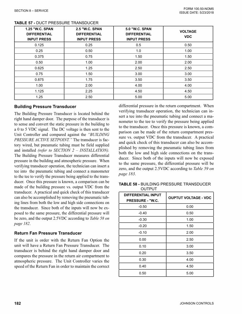
JOHNSON CONTROLS182
FORM 100.50-NOM5ISSUE DATE: 5/23/2018SECTION 8 – SERVICE
TABLE 57 - DUCT PRESSURE TRANSDUCER1.25 "W.C. SPANDIFFERENTIALINPUT PRESS
2.5 "W.C. SPANDIFFERENTIALINPUT PRESS
5.0 "W.C. SPANDIFFERENTIALINPUT PRESS
VOLTAGEVDC
0.125 0.25 0.5 0.500.25 0.50 1.0 1.00
0.375 0.75 1.50 1.500.50 1.00 2.00 2.00
0.625 1.25 2.50 2.500.75 1.50 3.00 3.00
0.875 1.75 3.50 3.501.00 2.00 4.00 4.00
1.125 2.25 4.50 4.501.25 2.50 5.00 5.00
Building Pressure TransducerThe Building Pressure Transducer is located behind the right hand damper door. The purpose of the transducer is to sense and convert the static pressure in the building to a 0 to 5 VDC signal. The DC voltage is then sent to the Unit Controller and compared against the “BUILDING PRESSURE ACTIVE SETPOINT.” The transducer is fac-tory wired, but pneumatic tubing must be field supplied and installed (refer to SECTION 2 – INSTALLATION). The Building Pressure Transducer measures differential pressure in the building and atmospheric pressure. When verifying transducer operation, the technician can insert a tee into the pneumatic tubing and connect a manometer to the tee to verify the pressure being applied to the trans-ducer. Once this pressure is known, a comparison can be made of the building pressure vs. output VDC from the transducer. A practical and quick check of this transducer can also be accomplished by removing the pneumatic tub-ing lines from both the low and high side connections on the transducer. Since both of the inputs will now be ex-posed to the same pressure, the differential pressure will be zero, and the output 2.5VDC according to Table 58 on page 182.
Return Fan Pressure TransducerIf the unit is order with the Return Fan Option the unit will have a Return Fan Pressure Transducer. The transducer is behind the right hand damper door and compares the pressure in the return air compartment to atmospheric pressure. The Unit Controller varies the speed of the Return Fan in order to maintain the correct
differential pressure in the return compartment. When verifying transducer operation, the technician can in-sert a tee into the pneumatic tubing and connect a ma-nometer to the tee to verify the pressure being applied to the transducer. Once this pressure is known, a com-parison can be made of the return compartment pres-sure vs. output VDC from the transducer. A practical and quick check of this transducer can also be accom-plished by removing the pneumatic tubing lines from both the low and high side connections on the trans-ducer. Since both of the inputs will now be exposed to the same pressure, the differential pressure will be zero, and the output 2.5VDC according to Table 59 on page 183.
TABLE 58 - BUILDING PRESSURE TRANSDUCER OUTPUT
DIFFERENTIAL INPUTPRESSURE - "W.C.
OUPTUT VOLTAGE - VDC
-0.50 0.00
-0.40 0.50
-0.30 1.00
-0.20 1.50
-0.10 2.00
0.00 2.50
0.10 3.00
0.20 3.50
0.30 4.00
0.40 4.50
0.50 5.00

JOHNSON CONTROLS 183
SECTION 8 – SERVICEFORM 100.50-NOM5 ISSUE DATE: 5/23/2018
8
TABLE 59 - RETURN FAN PRESSURE TRANSDUC-ER OUTPUT
DIFFERENTIAL INPUTPRESSURE - "W.C.
OUPTUT VOLTAGE - VDC
-1.00 0.00-0.80 0.50-0.60 1.00-0.40 1.50-0.20 2.000.00 2.500.20 3.000.40 3.500.60 4.000.80 4.501.00 5.00
Discharge Pressure TransducerThe discharge Pressure Transducer is located in the common discharge line of the tandem compressors for each refrigerant circuit. The purpose of this transducer is to sense and convert the discharge pressure into a DC voltage. The DC voltage is then sent to the Unit Controller where it is used to control the number of condenser fan when the unit is in cooling operation. The discharge pressure value, in PSIG, is displayed by the User Interface.
The Discharge Transducer has a range of 0 to 650 PSIG, with a linear output of 0 to 5 DC volts. Table 60 on page 183 illustrates the DC voltage output from the transducer for a given discharge pressure.
Suction Pressure TransducerThe optional suction pressure transducer is located in the common suction line of the tandem compressors for each refrigerant circuit. The purpose of the trans-ducer is to sense and convert the suction pressure to a DC voltage. The DC voltage is then sent to the Unit Controller where it is displayed by the User Interface. When this option is installed the Unit Controller will also calculate and display the Evaporator Superheat value for the system.
The Suction Transducer has a range of 0 to 400 PSIG, with a linear output of 0 to 5VDC from. Table 60 on page 183 illustrates the DC voltage output from the transducer for a given suction pressure.
TABLE 60 - PRESSURE TRANSDUCERS
SUCTION TRANSDUCER DISCHARGE TRANSDUCER
PRESSURE PSIG
VOLTAGE VDC
PRESSURE PSIG
VOLTAGE VDC
0 0.5 0 0.525 0.75 32.5 0.750 1 65 0.975 1.25 97.5 1.1
100 1.5 130 1.3125 1.75 162.5 1.5150 2 195 1.7175 2.25 227.5 1.9200 2.5 260 2.1225 2.75 292.5 2.3250 3 325 2.5275 3.25 357.5 2.7300 3.5 390 2.9325 3.75 422.5 3.1350 4 455 3.3375 4.25 487.5 3.5400 4.5 520 3.7
552.5 3.9585 4.1
617.5 4.3650 4.5
Humidity SensorsThe humidity sensor outputs a 0 to 5VDC from in re-sponse to the relative humidity sensed. An outdoor air humidity sensor is used whenever the economizer is configured for single or dual enthalpy. A return air humidity sensor is used whenever the economizer is configured for dual enthalpy. A humidity sensor is also used to monitor the humidity in the space between the slab an Table 61 on page 184 gives the relationship between the voltage output of the humidity sensor and the % relative humidity.
CO2 SensorTwo CO2 sensors are used in conjunction with the “DEMAND VENTILATION” option. In “DEMAND VENTILATION” the Unit Control monitors the CO2 level of the outdoor air and the CO2 level in the con-ditioned space and varies the amount of ventilation air based on the relationship between these two values. Table 62 on page 184 gives the VDC from output for a given CO2 level.

JOHNSON CONTROLS184
FORM 100.50-NOM5ISSUE DATE: 5/23/2018SECTION 8 – SERVICE
TABLE 61 - HUMIDITY SENSOR OUTPUTS%
RELATIVE HUMIDITY
OUTPUTVOLTAGE
VDC
% RELATIVE HUMIDITY
OUTPUTVOLTAGE
VDC5 0.25 55 2.75
10 0.50 60 3.0015 0.75 65 3.2520 1.00 70 3.5025 1.25 75 3.7530 1.50 80 4.0035 1.75 85 4.2540 2.00 90 4.5045 2.25 95 4.7550 2.50 100 5.00
Furnace Status InputThe Unit Controller monitors the operation of the Staged and Modulating Gas Heat sections and displays the status through the STATUS screen of the User In-terface. The operation of each of the gas heat sections is monitored by a multiplexer installed in the gas heat section. When a gas heat section is energized, it sends a 24-volt signal to the multiplexer. The multiplexer takes the five “ON”/”OFF” inputs and converts them into a 0 to 5VDC signal that is sent to the Unit Con-troller. The Unit Controller then decodes this analog input and displays the furnace section status. Table 63 on page 185 and Table 64 on page 185 show the relationship between the DC voltage and the furnace operation status.
TABLE 62 - CO2 SENSOR OUTPUT
PPM CO2OUTPUT
VOLTAGE VDC
PPM CO2OUTPUT
VOLTAGE VDC
80 0.20 1120 2.80160 0.40 1200 3.00240 0.60 1280 3.20320 0.80 1360 3.40400 1.00 1440 3.60480 1.20 1520 3.80560 1.40 1600 4.00640 1.60 1680 4.20720 1.80 1760 4.40800 2.00 1840 4.60880 2.20 1920 4.80960 2.40 2000 5.00
1040 2.60

JOHNSON CONTROLS 185
SECTION 8 – SERVICEFORM 100.50-NOM5 ISSUE DATE: 5/23/2018
8
TABLE 63 - FURNACE STATUS INPUT MODULATING GAS HEATMINVDC
MAXVDC
MODULATING FURNACE 1A STATUS
FURNACE 1AHIGH STATUS
FURNACE 2STATUS
FURNACE 3 STATUS
FURNACE 1B STATUS
0.086 0.166 OFF OFF OFF OFF OFF0.224 0.313 ON OFF OFF OFF OFF0.361 0.461 OFF ON OFF OFF OFF0.499 0.609 ON ON OFF OFF OFF0.637 0.756 OFF OFF ON OFF OFF0.774 0.904 ON OFF ON OFF OFF0.912 1.051 OFF ON ON OFF OFF1.050 1.199 ON ON ON OFF OFF1.187 1.346 OFF OFF OFF ON OFF1.325 1.494 ON OFF OFF ON OFF1.463 1.641 OFF ON OFF ON OFF1.600 1.789 ON ON OFF ON OFF1.738 1.936 OFF OFF ON ON OFF1.876 2.084 ON OFF ON ON OFF2.013 2.231 OFF ON ON ON OFF2.151 2.379 ON ON ON ON OFF2.289 2.526 OFF OFF OFF OFF ON2.426 2.674 ON OFF OFF OFF ON2.564 2.821 OFF ON OFF OFF ON2.702 2.969 ON ON OFF OFF ON2.839 3.116 OFF OFF ON OFF ON2.977 3.264 ON OFF ON OFF ON3.115 3.411 OFF ON ON OFF ON3.252 3.559 ON ON ON OFF ON3.390 3.706 OFF OFF OFF ON ON3.528 3.854 ON OFF OFF ON ON3.665 4.001 OFF ON OFF ON ON3.803 4.149 ON ON OFF ON ON3.941 4.296 OFF OFF ON ON ON4.078 4.444 ON OFF ON ON ON4.216 4.592 OFF ON ON ON ON4.354 4.739 ON ON ON ON ON
TABLE 64 - FURNACE STATUS INPUT STAGED GAS HEATMIN VDC MAX VDC FURNACE 1 STATUS FURNACE 2 STATUS FURNACE 3 STATUS
0.086 0.166 OFF OFF OFF0.224 0.313 ON OFF OFF0.361 0.461 OFF ON OFF0.499 0.609 ON ON OFF0.637 0.756 OFF OFF ON0.774 0.904 ON OFF ON0.912 1.051 OFF ON ON1.050 1.199 ON ON ON

JOHNSON CONTROLS186
FORM 100.50-NOM5ISSUE DATE: 5/23/2018SECTION 8 – SERVICE
FAULTSA fault is defined as an abnormal condition, which results in the shutdown of an operating system or the complete unit. The presence of a fault condition indi-cates a situation in which possible damage to the unit may occur if the unit or system were allowed to con-tinue to operate. There are four types of faults.
• UNIT LOCKOUT – The complete unit is shut-down and locked out. A manual reset is required to restart the unit after the fault has been corrected.
• SYSTEM LOCKOUT – One of the compres-sor systems or other component is shutdown and locked out. A manual reset is required to restart the system after the fault has been corrected.
• UNIT AUTO RESET – The complete unit is shut-down but the unit will restart automatically when the fault condition is cleared.
• SYSTEM AUTO RESET – One of the compres-sor systems or other component is shut down but the system or component will restart automati-cally when the fault condition is cleared.
A UNIT LOCKOUT can be reset by turning the “LO-CAL STOP” switch OFF for 5 seconds and then back ON. If the cause of the lockout has been corrected the unit will reset and begin proper operation.
A SYSTEM LOCKOUT except for COMPR # LOCK-OUT and COMPR # LPCO SAFETY LOCKOUT can be reset by turning the “LOCAL STOP” switch OFF for 5 seconds and then back ON. A COMPR # LOCK-OUT and COMPR # LPCO SAFETY LOCKOUT must be reset by entering the OPTION key and the COMPRESSOR SYSTEMS # subsection, which has the lockout. Then use the up and down arrow key to go to COMP SYS # STATUS. The current status will be LOCKOUT. Press the check key (√) and use the right arrow key to change LOCKOUT to RUN.
In addition to faults the User Interface will also display warnings. A warning is defined as an abnormal condi-tion under which the unit continues to operate. Warn-ings will not require the unit to shut down; however, they may require the Unit Controller to disable certain functions that may result in the unit operating less ef-ficiently or eliminate certain features.
Table 67 on page 193 lists the faults / warnings that will be displayed under the STATUS and HISTORY keys of the User Interface. When a fault is present line two of the effected STATUS screen display (UNIT-OVERALL STATUS, COMPRESSOR SYSTEM 1,
COMPRESSOR SYSTEM 2, COMPRESSOR SYS-TEM 3, HEATING SYSTEM, ECONOMIZER SYS-TEM, SUPPLY SYSTEM, EXHAUST SYSTEM, VENTILATION SYSTEM, or SENSOR / MISC STA-TUS) will change nomenclature to indicate a WARN-ING, SAFETY TRIP, SAFETY FAULT, or SAFETY LOCKOUT is present. A fault / warning description, method of reset and conditions under which the infor-mation is displayed is also contained in the table. Ad-ditional information for each of the faults is contained under their respective section in SECTION 5 – SE-QUENCE OF OPERATION.
When a fault is declared, the Unit Controller will re-cord the time of occurrence, the date of occurrence, and a complete unit snapshot at the time of each oc-currence in the HISTORY buffer. This data can be re-trieved using the HISTORY key of the User Interface.
The HISTORY buffer stores the data from the last ten faults from the most recent (HISTORY 01) to the old-est (HISTORY 10). No fault HISTORY is eliminated once recorded other than being “pushed off” of the end of the list by a new fault when the buffer becomes full.
Warnings are only displayed in the HISTORY buffer while they are active. When the problem that gener-ated the WARNING is corrected the record is removed from the buffer. The Unit Controller does not record the time of occurrence, the date of occurrence, or a complete unit snapshot at the time of occurrence for a WARNING.
The HISTORY buffer is password protected and a level 2 password must be entered in order to view the data.
When the HISTORY key is pressed, the password prompt will appear. After the proper level 2 password has been entered the screen will show the first active warning. If there are no active warnings present, the first fault will be displayed. If there are no faults in the HISTORY buffer, the screen will display “NO FAULT.” See SECTION 6 – USER INTERFACE CON-TROL CENTER for additional information on how to navigate through the HISTORY menu.
In addition to the items listed in Table 67 on page 193 the following items listed below are contained under the HISTORY key.
“COMPRESSOR SYSTEM (1,2,OR 3) CLEAR” - Whenever there is a compressor safety trip the Unit Controller initiates the “COMPR STATUS CLEAR TIME (1,2, OR 3)” timer. The Unit Control records the time it takes for the trip to clear. When the fault clears “COMPRESSOR SYSTEM (1,2,OR 3) CLEAR”

JOHNSON CONTROLS 187
SECTION 8 – SERVICEFORM 100.50-NOM5 ISSUE DATE: 5/23/2018
8
shows the time it took for the fault to clear in the HIS-TORY buffer.
“COMPRESSOR SYSTEM (1,2,OR 3)TIME OUT” – If the “COMPR STATUS CLEAR TIME (1,2, OR 3)” timer reaches 60 minutes a “COMPRESSOR SYSTEM (1,2,OR 3)TIME OUT” will be indicated in the HIS-TORY buffer. In most cases this indicates the com-pressor circuit over current protector opened. The compressor circuit over current protector is a manual reset device and the circuit would not reset in the re-quired 60 minute time frame. The STATUS key will display the message “COMP SYS (1,2,OR 3) STA-
TUS” “SAFETY LOCKOUT.” The Unit Controller locks out the corresponding compressor system when a “COMPRESSOR SYSTEM (1,2,OR 3)TIME OUT” is declared.
“COMPR SYSTEM (1,2,OR 3) INHIBIT” – This WARNING indicates the compressor system safety circuit experienced a trip but reset prior to the explora-tion of the 60 minute reset time function. If the safety circuit does not reset in 60 minutes it will be replaced with a “COMPRESSOR SYSTEM (1,2,OR 3)TIME OUT” message.
FIGURE 61 - I/O CONTROL BOARD
LD10790C
TB
5T
B3
TB
6T
B4
J2 J1J3J4
J5
J6
J7
TB9
TB8 TB1
TB7
I/O
IPU
ANALOGOUTPUTS
See Fig. 8-5
BINARY INPUTS
See Fig. 8-4
BINARY INPUTS
See Fig. 8-4
BINARY OUTPUTS
See Fig. 8-3
BINARY OUTPUTS
See Fig. 8-3
ANALOGINPUTS
See Fig. 8-6
ANALOGINPUTS
See Fig. 8-6
BINARY OUTPUTS
J12-3 5VDC
J12-1 GND
FLASH CARD
J11-1 GND
J11-3 12 VDC
12 VDC FUSE
5 VDC FUSE
See Figure 64
See Figure 61
See Figure 61
See Figure 62
See Figure 62
See Figure 63
See Figure 64

JOHNSON CONTROLS188
FORM 100.50-NOM5ISSUE DATE: 5/23/2018SECTION 8 – SERVICE
FIGURE 62 - I/O CONTROL BOARD - BINARY OUTPUTS
LD10791D
TB
5T
B3
TB
6T
B4
J2 J1J3J4
J5
J6
J7
TB9
TB8 TB1
TB7
I/O CONTROL
IPU CONTROL
TB5-5 24VAC (395)TB5-4 SYS 1 COMP B (428)
TB5-3 24VAC (399)
TB5-1 24VAC (399)
TB3-8 COND FAN #2 (424)
TB3-10 COND FAN #4 (426)
TB6-3 RETURN/EXHAUST FAN (422)
TB4-9 FURN OUTPUT 7 (576)
TB4-7 FURN OUTPUT 5 (574)
TB4-5 FURN OUTPUT 4 (573)
TB4-3 FURN OUTPUT 2 (571)
TB4-1 24VAC (413)
TB1-12 VAV HEAT (383)
TB1-11 VAV HEAT COMM (382)TB1-10 SENSOR/FAULT ALARM (381)
TB1-9 SENSOR/FAULT ALARM COMM (380)
TB6-1 24VAC (301)
TB3-6 24VAC (301)
TB5-7 24VAC (395) TB5-8 SYS 2 COMP B (430)
TB5-6 SYS 2 COMP A (429)
TB5-2 SYS 1 COMP A (427)
TB3-9 COND FAN #3 (425)
TB3-7 COND FAN #1 (433)
TB6-2 SUPPLY FAN (421)
TB4-8 FURN OUTPUT 6 (575)
TB4-4 FURN OUTPUT 3 (572)
TB4-2 FURN OUTPUT 1 (570)
TB4-6 24VAC (413)
TB1-8 COOLING/HEATING FAULT ALARM (379)TB1-7 COOLING/HEATING FAULT ALARM COMM (378)
TB1-6 SUPPLY FAN FAULT ALARM COMM (377)TB1-5 SUPPLY FAN FAULT ALARM (376)
TB1-4 EXHAUST/RETURN FAN VFD START (387)TB1-3 EXHAUST/RETURN FAN VFD START (386)
TB1-2 SUPPLY FAN VFD START (385)TB1-1 SUPPLY FAN VFD START (384)

JOHNSON CONTROLS 189
SECTION 8 – SERVICEFORM 100.50-NOM5 ISSUE DATE: 5/23/2018
8
FIGURE 63 - I/O CONTROL BOARD - BINARY INPUTS
LD12945
TB
3T
B6
TB
4
J2 J1J3J4
J5
J6
J7
TB9
TB8 TB1
TB7
I/O CONTROL
IPU CONTROL
ANALOGOUTPUTSSee Fig. 8-4
BINARY OUTPUTSSee Fig. 8-2
BINARY OUTPUTSSee Fig. 8-2
ANALOGINPUTS
See Fig. 8-5
ANALOGINPUTS
See Fig. 8-5
BINARY OUTPUTS
TB8-14 W2 (361)TB8-13 W1 (359)
TB8-11 Y2 (358)TB8-10 Y1 (357)
TB8-8 FAN (G) (356)TB8-7 SMOKE PURGE 3 (355)
TB8-5 SMOKE PURGE 2 (354)TB8-4 SMOKE PURGE 1 (353)TB8-2 OCC/UNOCC (352)
TB8-1 SHUTDOWN (351)
TB8-16 24VAC COMM (304)
TB7-16 24VAC COMM (302)
TB7-14 HW FREEZESTAT (389)
TB7-12 24VAC (391)
TB7-10 SUPPLY/RETURN FAN STATUS (392)
TB7-2 COMP 2 SAFETY CIRCUIT (398)
TB7-15 24VAC (388)
TB7-13 FILTER STATUS (390)
TB7-9 24VAC (393)
TB7-7 COMP 2 LOW PRESS (397)
TB7-5 COMP 1 LOW PRESS (396)
TB7-3 24 VAC (301)
TB7-1 COMP 1 SAFETY CIRCUIT (399)
FIGURE 64 - I/O CONTROL BOARD - ANALOG OUTPUTS
LD13000
TB9 I/O CONTROL
TB9-12 BYPASS DAMPER COM (412)
TB9-10 HOT WATER STEAM VALVE COM (410)TB9-9 HOT WATER STEAM VALVE + (409)
TB9-8 EXHAUST DAMPER COM (408)TB9-7 EXHAUST DAMPER + (407)TB9-6 OA/RA DAMPER COM (406)
TB9-5 OA/RA DAMPER + (405)TB9-4 EXHAUST/RETURN VFD COM (404)
TB9-3 EXHAUST/RETURN VFD + (403)TB9-2 SUPPLY FAN VFD COM (402)
TB9-1 SUPPLY FAN VFD + (401)
TB9-11 BYPASS DAMPER + (411)
FIGURE 65 - I/O CONTROL BOARD - ANALOG INPUTS
J2 J1J3J4
J5
J6
J7
I/O CONTROL
5 4 3 2 1
10 9 8 7 6
15 14 13 12 11
J4, J5, J6, J7 PINOUTS
4 3 2 1
8 7 6 5
12 11 10 9
J1, J2, J3 PINOUTS
LD10794
(SEE Table 65 on page 190 FOR PIN OUTS)

JOHNSON CONTROLS190
FORM 100.50-NOM5ISSUE DATE: 5/23/2018SECTION 8 – SERVICE
TABLE 65 - I/O CONTROL BOARD - ANALOG INPUT PIN OUTSPINNO.
SIGNAL
J1-1 INPUT SUPPLY AIR TEMP (308)J1-5 SHIELD SUPPLY AIR TEMPJ1-9 REF SUPPLY AIR TEMP 5VDC (309)J1-2 INPUT HEAT ENTER TEMP (310)J1-6 SHIELD HEAT ENTER TEMP
J1-10 REF HEAT ENTER TEMP 5VDC (311)J1-3 INPUT FLEX EVAP TEMP (312)J1-7 SHIELD FLEX EVAP TEMPJ1-11 REF FLEX EVAP TEMP 5VDC (313)J2-1 INPUT OUTSIDE AIR TEMP (329)J2-5 SHIELD OUTSIDE AIR TEMPJ2-9 REF OUTSIDE AIR TEMP 5VDC (330)J2-2 INPUT RETURN AIR TEMP (331)J2-6 SHIELD RETURN AIR TEMP
J2-10 REF RETURN AIR TEMP 5VDC (332)J2-3 INPUT OA HUM (333)J2-7 COM OA HUM (334)J2-4 INPUT RA HUM (335)J2-8 COM RA HUM (336)J3-1 INPUT SUCT TEMP SYS1 (347)J3-5 SHIELD SUCT TEMP SYS1J3-9 REF SUCT TEMP SYS1 5VDC (348)J3-2 INPUT SUCT TEMP SYS2 (349)J3-6 SHIELD SUCT TEMP SYS2
J3-10 REF SUCT TEMP SYS2 5VDC (350)
J3-4 INPUT SUCT PRESS SYS1 (317)
J3-8 COM SUCT PRESS SYS1 (318)J3-12 REF SUCT PRESS SYS1 5VDC (319)J4-1 INPUT SUCT PRESS SYS2 (320)J4-6 COM SUCT PRESS SYS2 (321)J4-11 REF SUCT PRESS SYS2 5VDC (322)J4-3 INPUT DISCH PRESS SYS1 (323)J4-8 COM DISCH PRESS SYS1 (324)
PINNO.
SIGNAL
J4-13 REF DISCH PRESS SYS1 5VDC (325)J4-4 INPUT DISCH PRESS SYS2 (326)J4-9 COM DISCH PRESS SYS2 (327)
J4-14 REF DISCH PRESS SYS2 5VDC (328)J5-1 INPUT GAS HEAT STATUS (542)J5-6 COM GAS HEAT STATUS (543)J5-11 REF GAS HEAT STATUS 5VDC (541)J5-2 INPUT OA CO2 (343)J5-7 COM OA CO2 (344)J5-3 INPUT RA CO2 (345)J5-8 COM RA CO2 (346)J6-1 INPUT RETURN FAN PRESS (341)J6-6 COM RETURN FAN PRESS (342)J6-2 INPUT DUCT PRESS (337)J6-7 COM DUCT PRESS (338)J6-3 INPUT BLDG PRESS (339)J6-8 COM BLDG PRESS (340)J7-1 INPUT ZONE TEMP SENSOR (363)J7-6 SHIELD ZONE TEMP SENSOR (364)J7-11 REF ZONE TEMP SENSOR 5VDC (362)J7-2 INPUT FLEXSYS SLAB SENSOR (366)J7-7 SHIELD FLEXSYS SLAB SENSOR (367)
J7-12 REF FLEXSYS SLAB SENSOR 5VDC (365)
J7-3INPUT FLEXSYS UNDER FLOOR HUM (368)
J7-8 COM FLEXSYS UNDER FLOOR HUM (369)J7-4 INPUT SAT RESET (371)J7-9 COM SAT RESET (372)
J7-14 REF SAT RESET 5VDC (370)J7-5 INPUT DUCT STATIC RESET (374)
J7-10 COM DUCT STATIC RESET (375)J7-15 REF DUCT STATIC RESET 5VDC (373)

JOHNSON CONTROLS 191
SECTION 8 – SERVICEFORM 100.50-NOM5 ISSUE DATE: 5/23/2018
8
TABLE 66 - WARNING DESCRIPTION TABLEHISTORY SCREEN
WORDING DESCRIPTION RESET SHOW WHEN
UNIT TYPE IS
STATUS SCREEN
WORDING
FAULT OUTPUT
TYPE
WRN-BUILDING
PRS
BUILDING STATIC PRES more than 0.45 "W.C. OR less than -0.45 "W.C.
FOR 10 SECONDS. POWER EXHAUST REVERTS TO NONE OR ON/OFF
AUTO RESET
POWER EXHAUST
OTHER THAN NONE OR ON - OFF DAMPER
EXHAUST SYS STATUS
WARNING
SENSOR/MISC FAULT
WRN-CO2 SENSOR 1 OUTSIDE
OUTSIDE CO2 SENSOR OUT OF RANGE FOR more than or equal to 15
MINUTES
AUTO RESET
VENTILATION CONTROL EQUALS DEMAND
VENTILATION SYS STATUS
WARNING
SENSOR/MISC FAULT
WRN-CO2 SENSOR 2
INSIDE
OUTSIDE CO2 SENSOR OUT OF RANGE FOR more than or equal to 15
MINUTES
AUTO RESET
VENTILATION CONTROL EQUALS DEMAND
VENTILATION SYS STATUS
WARNING
SENSOR/MISC FAULT
WRN-COMPR SYSTEM *
INHIBIT
SEE DESCRIPTION AT THE END OF THIS TABLE
AUTO RESET
COOLING HEATING
FAULT
WRN-DIRTY FILTER 1
THE FILTER STATUS INPUT IS CLOSED FOR more than or equal to 1
MINUTE
AUTO RESET
DIRTY FILTER SWITCH IS INSTALLED
FILTER STATUS CHANGE
SENSOR/MISC FAULT
WRN-DISCHARGE
PRS SENSOR*
THE DISCHARGE PRESURE FOR THAT SYSTEM IS OUT OF RANGE FOR more
than or equal to 10 SECONDS
AUTO RESET
PRESS TRANS PKG IS ON FOR THE SYSTEM
SENSOR/MISC
STATUS WARNING
SENSOR/MISC FAULT
WRN-DUCT PRS XDCR
SUPPLY FAN OUTPUT ON, SUPPLY FAN STATUS MUST BE RUNNING FOR 5 MINUTES, STATIC PRESS CURRENT
less than or equal to (0.333 X DUCT STATIC PRESS ACTIVE SP) FOR 30
SECONDS
AUTO RESET
UNIT TYPE IS VAV OR FLEXSYS
SUPPLY SYS STATUS
WARNINGFAN FAULT
WRN-EXHAUST FAN
THE EXHAUST FAN OUTPUT IS ON FOR 45 SECONDS AND THE RUN
VERIFICATION INPUT IS LOW (OPEN) FOR 10 SECONDS
AUTO RESET
POWER EXHAUST
OTHER THAN NONE
EXHAUST SYSTEM STATUS
WARNING
SENSOR/MISC FAULT
WRN-FREEZESTAT
TRIP
THE HW/STEAM FREEZSTAT CIRCUIT GOES LOW (OPEN) BUT GOES HIGH
(CLOSED) WITHIN 5 MINUTES
AUTO RESET
HEATING SYSTEM TYPE EQUALS HOT
WATER STEAM
SENSOR/MISC
STATUS WARNING
COOLING HEATING
FAULT
WRN-FURNACE
MULTIPLEXER FAULT
ON MODULATING GAS THE HEAT, BINARY OUTPUTS DO NOT MATCH THE GAS FURNACE STATUS INPUT.
SEE Table 63 on page 185 OR NO FURNACE STATUS INPUT ON STAGED
GAS
AUTO RESET
HEATING SYSTEM
TYPE EQUALS MODULATING
GAS OR STAGED GAS
SENSOR/MISC
STATUS WARNING
COOLING HEATING
FAULT
WRN-GAS FURNACE
THE HEAT BINARY OUTPUTS DO NOT MATCH THE GAS FURNACE STATUS
INPUT. SEE Table 64 on page 185
AUTO RESET
HEATING SYSTEM
TYPE EQUALS STAGED GAS
COOLING HEATING
FAULT
* CAN BE 1, 2, OR 3 # CAN BE A OR B

JOHNSON CONTROLS192
FORM 100.50-NOM5ISSUE DATE: 5/23/2018SECTION 8 – SERVICE
TABLE 66 - WARNING DESCRIPTION TABLE (CONT'D)
HISTORY SCREEN
WORDING DESCRIPTION RESET SHOW WHEN
UNIT TYPE IS
STATUS SCREEN
WORDING
FAULT OUTPUT
TYPE
WRN-HET SENSOR
THE HEAT ENTERING SENSOR IS OUT OF RANGE FOR more than or equal to
10 SECONDS
AUTO RESET
HEATING SYSTEM TYPE
IS STAGED GAS OR
ELECTRIC
SENSOR/MISC
STATUS WARNING
SENSOR/MISC FAULT
WRN-HIGH DP UNLOAD *#
BOTH COMPRESSOR ARE ON FOR THE SYSTEM AND THE DISCHARGE
PRESS IS more than or equal to TO THE SYSTEM UNLOADING PRESSURE
FOR 10 SECONDS
AUTO RESET
PRESS TRANS PKG IS ON FOR THE SYSTEM
SENSOR/MISC
STATUS WARNING
SENSOR/MISC FAULT
WRN-LOW AMBIENT TEMP *
THE OUTDOOR TEMP IS less than or equal to THE MECH COOL LOCKOUT
TEMP
AUTO RESET
LOW AMBIENT PKG IS NOT INSTALLED FOR THE SYSTEM
COMP SYS * STATUS LOW AMB
INHIBIT
SENSOR/MISC FAULT
WRN-LOW SUCTION TEMP *#
THE SUCTION TEMP IS LEES THAN THE SUCTION TEMP LOW LIMIT FOR
10 CONTINUOUS SECONDS
AUTO RESET
COMP SYS * STATUS SUCTION TEMP UNL
# ON
SENSOR/MISC FAULT
WRN-OA FLOW PRS 1
REFER TO AIR MEASUREMENT STATION SENSOR FAULTS IN SECTION 5 OF THE MANUAL
LOCKS OUT THE AIR
MEASURING STATION
DAMPER HARDWARE IS MINIMUM IAQ, FULL IAQ, 1/3-2/3 IAQ, TEK AIR FULL IAQ
SENSOR/MISC
STATUS WARNING
SENSOR/MISC FAULT
WRN-OA FLOW PRS 2
REFER TO AIR MEASUREMENT STATION SENSOR FAULTS IN SECTION 5 OF THE MANUAL
LOCKS OUT THE AIR
MEASURING STATION
DAMPER HARDWARE IS
1/3 - 2/3 IAQ
SENSOR/MISC
STATUS WARNING
SENSOR/MISC FAULT
WRN-OUTSIDE AIR
RH
OUTSIDE AIR TEMP more than or equal to 32 °F FOR 10 SECONDS
OUTDOOR AIR HUMIDITY less than 5% FOR 10 SECONDS
AUTO RESET
ECONO INSTALLED
SINGLE ENTHALPY OR DUAL
ENTHALPY
SENSOR/MISC
STATUS WARNING
SENSOR/MISC FAULT
WRN-RETURN AIR RH
RETURN AIR TEMP more than or equal to 32 °F FOR 10 SECONDS
RETURN AIR HUMIDITY less than 5% FOR 10 SECONDS
AUTO RESET
ECONO INSTALLED
DUAL ENTHALPY
SENSOR/MISC
STATUS WARNING
SENSOR/MISC FAULT
WRN-RETURN FAN XDCR
SUPPLY FAN OUTPUT IS ON AND RETURN FAN PRESS CURRENT less
than -0.95 "W.C. OR more than 0.95 "W.C. FOR 30 SECONDS OR SUPPLY FAN OUTPUT IS OFF AND RETURN
FAN PRESSURE CURRENT less than -0.1 "W.C. OR more than 0.1 "W.C. FOR
5 MINUTES
AUTO RESET
POWER EXHAUST TYPE IS
RETURN FAN W/EXH OR
RETURN FAN W/O EXH
SUPPLY SYS STATUS
WARNINGFAN FAULT
* CAN BE 1, 2, OR 3 # CAN BE A OR B

JOHNSON CONTROLS 193
SECTION 8 – SERVICEFORM 100.50-NOM5 ISSUE DATE: 5/23/2018
8
TABLE 66 - WARNING DESCRIPTION TABLE (CONT'D)
HISTORY SCREEN
WORDING DESCRIPTION RESET SHOW WHEN
UNIT TYPE IS
STATUS SCREEN
WORDING
FAULT OUTPUT
TYPE
WRN-SLAB TEMP
SENSOR
UDERFLOOR SLAB TEMP SENSOR IS OUT OF RANGE FOR more than or
equal to10 SECONDS
AUTO RESET
UNIT TYPE IS FLEXSYS AND DEW
POINT RESET IS USER
ENABLED
SENSOR/MISC
STATUS WARNING
SENSOR/MISC FAULT
WRN-SUCTION PRS
SENSOR *
SUCTION PRESSURE OUT OF RANGE FOR more than or equal to 10 SECONDS
AUTO RESET
PRESS TRANS PKG IS ON FOR THE SYSTEM
SENSOR/MISC
STATUS WARNING
SENSOR/MISC FAULT
WRN-SUCTION
TEMP SENSOR * #
SUCTION TEMPERATURE SENSOR IS OUT OF RANGE FOR more than or
equal to 10 SECONDS
AUTO RESET
SENSOR/MISC
STATUS WARNING
SENSOR/MISC FAULT
WRN-UNDER FLOOR RH SENSOR
UDERFLOOR AIR HUMIDITY IS less than 5% FOR more than or equal to 5
MINUTES
AUTO RESET
UNIT TYPE IS FLEXSYS AND DEW
POINT RESET IS USER
ENABLED
SENSOR/MISC
STATUS WARNING
SENSOR/MISC FAULT
* CAN BE 1, 2, OR 3 # CAN BE A OR B
TABLE 67 - FAULT AUTO - RESETHISTORY SCREEN
WORDINGDESCRIPTION RESET HOW WHEN UNIT
TYPE IS
STATUS SCREEN
WORDING
FAULT OUTPUT
TYPEAUTO RESET-
COMPRESSOR SYSTEM * CLEAR
SEE DESCRIPTION BELOWAUTO
RESET
AUTO RESET-COMPRESS
SYSTEM * TRIP 1
THE SAFETY INPUT CHAIN IS OPEN (FAULTED) FOR MORE THAN TWO SECONDS WITH EITHER OR BOTH
COMPRESSOR OF THE SYSTEM ON AND THIS IS THE FIRST TRIP IN A 120
MINUTE SPAN
AUTO RESET
COMP SYSTEM * STATUS SAFVETY
TRIP
COOLING HEATING
FAULT
AUTO RESET COMPRESSOR
SYSTEM * TRIP 2
THE SAFETY INPUT CHAIN IS OPEN (FAULTED) FOR MORE THAN TWO SECONDS WITH EITHER OR BOTH
COMPRESSOR OF THE SYSTEM ON AND THIS IS THE SECOND TRIP IN A
120 MINUTE SPAN
AUTO RESET
COMP SYSTEM * STATUS
SAFETY TRIP
COOLING HEATING
FAULT
AUTO RESET-LOW SUCTION
TEMP
EITHER IS COMPRESSOR ON AND THE TEMPERATURE - SUCTION IS LESS THAN OR EQUAL TO THE SUCTION LOW LIMIT FOR 10 CONTINUOUS SECONDS AND AFTER THE COMPRESSOR WAS TURNED OFF THE TEMPERATURE DID NOT RISE ABOVE THE LIMIT.
AUTO RESET
COMP SYSTEM * STATUS SAFETY FAULT
SENSOR/MISC FAULT
* CAN BE 1, 2, OR 3

JOHNSON CONTROLS194
FORM 100.50-NOM5ISSUE DATE: 5/23/2018SECTION 8 – SERVICE
TABLE 67 - FAULT AUTO - RESET (CONT'D)
HISTORY SCREEN
WORDINGDESCRIPTION RESET HOW WHEN UNIT
TYPE IS
STATUS SCREEN
WORDING
FAULT OUTPUT
TYPE
AUTO RESET-LPCO * TRIP 1
THE LOW PRESSURE CUTOUT INPUT CHAIN IS OPEN (FAULTED) FOR MORE
THAN TWO SECONDS WITH EITHER OR BOTH COMPRESSOR OF THE
SYSTEM ON AND THIS IS THE FIRST TRIP IN A 120 MINUTE SPAN
AUTO RESET
COMP SYSTEM * STATUS SAFVETY
TRIP
COOLING HEATING
FAULT
AUTO RESET-LPCO * TRIP 2
THE LOW PRESSURE CUTOUT INPUT CHAIN IS OPEN (FAULTED) FOR
MORE THAN TWO SECONDS WITH EITHER OR BOTH COMPRESSOR OF
THE SYSTEM ON AND THIS IS THE SECOND TRIP IN A 120 MINUTE SPAN
AUTO RESET
COMP SYSTEM * STATUS SAFVETY
TRIP
COOLING HEATING
FAULT
AUTO RESET - MSAT SENSOR
MS SUPPLY AIR TEMP CURRENT SENSOR IS OUT OF RANGE FOR
MORE THAN OR EQUAL TO 10 SECONDS.
AUTO RESET
UNIT TYPE IS FLEXSYS
SENSOR/MISC STATUS
SAFETY LOCKOUT
SENSOR/MISC FAULT
AUTO RESET - POWER FAIL
POWER IS LOST WHEN THE UNIT OPERATING STATE IS RUN
AUTO RESET
AUTO RESET - RAT SENSOR
RETURN AIR TEMP CURRENT SENSOR IS OUT OF RANGE FOR
MORE THAN OR EQUAL TO 10 SECONDS
AUTO RESET
SENSOR/MISC STATUS
SAFETY FAULT
SENSOR/MISC FAULT
AUTO RESET - REMOTE I/O
COMM
NO COMMUNICATION FROM THE I/O BOARD FOR MORE THAN OR EQUAL
TO 5 SECONDS
AUTO RESET
SENSOR/MISC FAULT
AUTO RESET - STAGED INPUT
THE CONTROL HAS A COOLING AND HEATING THERMOSTAT INPUT AT THE SAME TIME FOR A PERIOD GREATER
THAN 10 SECONDS
AUTO RESET
SENSOR/MISC STATUS
SAFETY LOCKOUT
SENSOR/MISC FAULT
AUTO RESET - ZONE TEMP
SENSOR
ZONE TEMP CURRENT SENSOR IS OUT OF RANGE FOR MORE THAN OR
EQUAL TO 10 SECONDS
AUTO RESET
UNIT TYPE IS VAV AND NIGHT
SET BACK IS USER ENABLED OR UNIT TYPE IS SET TO CV AND THE CONTROL
METHOD IS SET TO ZONE
SENSOR HARDWIRED
SENSOR/MISC STATUS
SAFETY LOCKOUT
SENSOR/MISC FAULT
* CAN BE 1, 2, OR 3

JOHNSON CONTROLS 195
SECTION 8 – SERVICEFORM 100.50-NOM5 ISSUE DATE: 5/23/2018
8
TABLE 68 - FAULTS LOCKOUTHISTORY SCREEN
WORDINGDESCRIPTION RESET SHOW WHEN
UNIT TYPE IS
STATUS SCREEN
WORDING
FAULT OUTPUT
TYPELOCKOUT-
COMPRESSOR SYSTEM * TIME
OUT
SEE BELOWSYSTEM
LOCKOUT
COMP SYSTEM
* - SAFETY LOCKOUT
COOLING HEATING
FAULT
LOCKOUT - COMPRESSOR
SYSTEM *
HIGH PRESS SW, COMP MOTOR PROTECTOR, OR OVERCURRENT
PROTECTOR OPEN - 3 TIMES IN 120 MINUTES ON COMP SYSTEM *
SYSTEM LOCKOUT
COMP SYSTEM
* - SAFETY LOCKOUT
COOLING HEATING
FAULT
LOCKOUT - HGRH FAULT 1
HGRH SYSTEM IS INACTIVE, A COMP FROM CKT 2 IS ON, AND THE CURRENT SAT IS GREATER THAN/EQUAL TO THE
CURRENT EVAP AIR TEMP + 8.0 °F
SYSTEM LOCKOUT
HGRH IS INSTALLED
COMP SYSTEM
2 - SAFETY LOCKOUT
COOLING HEATING
FAULT
LOCKOUT - HGRH FAULT 2
HGRH SYSTEM IS ACTIVE, THE HGRH VALVE POSITION IS GREATER THAN
50%, AND THE CURRENT SAT IS LESS THAN/EQUAL TO THE CURRENT EVAP
AIR TEMP + 8.0 °F
SYSTEM LOCKOUT
HGRH IS INSTALLED
COMP SYSTEM
2 - SAFETY LOCKOUT
COOLING HEATING
FAULT
LOCKOUT-HIGH DUCT PRESSURE
DUCT STATIC PRESS CURRENT .+ DUCT STATIC OVER PRESSURE
UNIT LOCKOUT
UNIT TYPE IS VAV OR FLEXSYS
SUPPLY SYS STATUS
SAFETY LOCKOUT
FAN FAULT
LOCKOUT - HOT WATER FREEZE
THE HYDRONIC FREEZE STAT SWITCH REMAINED OPEN MORE THAN OR
EQUAL TO 5 MINUTES
UNIT LOCKOUT
HEAT TYPE HOT WATER /
STEAM
HEATING SYS STATUS
- SAFETY LOCKOUT
COOLING HEATING
FAULT
LOCKOUT-LPCOLOW PRESSURE CUTOUT OPEN - 3 TIMES IN 120 MINUTES ON COMPR
SYSTEM *
SYSTEM LOCKOUT
COMP SYSTEM * - SAFETY LOCKOUT
COOLING HEATING
FAULT
LOCKOUT - MANUAL STOP *
THE COMPRESSOR SYSTEM HAS BEEN PLACED IN THE STOP MODE
EITHER THROUGH THE USER INTERFACE OR BY A COMMUNICATED
INPUT
SYSTEM LOCKOUT
COMP SYS * STATUS DISABLED
LOCKOUT - MANUAL UNIT
STOP
THE UNIT IS SHUT DOWN THROUGH THE SHUT DOWN SWITCH ON
THE UNIT OR BY AN EXTERNAL HARDWIRED OR COMMUNICATED
INPUT
UNIT LOCKOUT
UNIT - OVERALL STATUS
LOCAL STOP
* CAN BE 1, 2, OR 3
“WRN - COMP SYSTEM * INHIBIT” - This WARNING indicates the compressor system safety circuit experienced a trip but reset prior to the exploration of the 60 minute reset time function. If the safety circuit does not reset in 60 minutes it will be replaced with a “LOCKOUT - COMPRESSOR SYSTEM * TIME OUT” message.
“AUTO RESET - COMPRESSOR SYSTEM * CLEAR” - When ever there is a compressor safety trip the Primary Unit Controller initiates the “COMPR STATUS CLEAR TIME *” timer. The Primary Unit Control records the time it takes for the trip to clear. When the fault clears “COMPRESSOR SYSTEM * CLEAR” shows the time it took for the fault to clear in the HISTORY buffer.
“LOCKOUT-COMPRESSOR SYSTEM * TIME OUT” – If the “COMPR STATUS CLEAR TIME *” timer reaches 60 minutes a “LOCKOUT - COMPRESSOR SYSTEM * TIME OUT” will be indicated in the HISTORY buffer.

JOHNSON CONTROLS196
FORM 100.50-NOM5ISSUE DATE: 5/23/2018SECTION 8 – SERVICE
TABLE 68 - FAULTS LOCKOUT (CONT'D)HISTORY SCREEN
WORDINGDESCRIPTION RESET SHOW WHEN
UNIT TYPE IS
STATUS SCREEN
WORDING
FAULT OUTPUT
TYPE
LOCKOUT - OAT SENSOR
OUTSIDE AIR TEMP SENSOR IS OUT OF RANGE FOR MORE THAN OR EQUAL
TO 10 SECONDS
UNIT LOCKOUT
COMP SYS * STATUS SAFETY
LOCKOUT; ECONO SYS
STATUS SAFETY
LOCKOUT
SENSOR/MISC FAULT
LOCKOUT - SAT SENSOR
SUPPLY AIR TEMP CURRENT SENSOR IS OUT OF RANGE FOR more than or
equal to 10 SECONDS
UNIT LOCKOUT
UNIT TYPE IS CONSTANT VOLUNE OR
VARIABLE AIR VOLUME
SENSOR/MISC FAULT
LOCKOUT-SUPPLY FAN
SUPPLY FAN STATUS IS LOW AND TIME FROM START more than or equal to 30
SEC UNIT LOCKOUT ON THE RETURN FAN STATUS IS LOW AND TIME FROM
START more than or equal to 30 SEC UNIT LOCKOUT
UNIT LOCKOUT
UNIT - OVERALL
STATUS UNIT LOCKOUT
FAN FAULT
* CAN BE 1, 2, OR 3
“WRN - COMP SYSTEM * INHIBIT” - This WARNING indicates the compressor system safety circuit experienced a trip but reset prior to the exploration of the 60 minute reset time function. If the safety circuit does not reset in 60 minutes it will be replaced with a “LOCKOUT - COMPRESSOR SYSTEM * TIME OUT” message.
“AUTO RESET - COMPRESSOR SYSTEM * CLEAR” - When ever there is a compressor safety trip the Primary Unit Controller initiates the “COMPR STATUS CLEAR TIME *” timer. The Primary Unit Control records the time it takes for the trip to clear. When the fault clears “COMPRESSOR SYSTEM * CLEAR” shows the time it took for the fault to clear in the HISTORY buffer.
“LOCKOUT-COMPRESSOR SYSTEM * TIME OUT” – If the “COMPR STATUS CLEAR TIME *” timer reaches 60 minutes a “LOCKOUT - COMPRESSOR SYSTEM * TIME OUT” will be indicated in the HISTORY buffer.

JOHNSON CONTROLS 197
SECTION 8 – SERVICEFORM 100.50-NOM5 ISSUE DATE: 5/23/2018
8
MULTI MEDIA CARDThe Unit Controller is made up of two separate con-trol boards, the PLUG IN I/O board and the IPU board. All the digital and analog inputs and outputs are con-nected to the PLUG IN I/O control. All the system logic is contained on the IPU board. The IPU board mounts on top of the PLUG IN I/O board and handles the communication between the PLUG IN I/O board and the User Interface. Another feature of this control system is the availability to connect a MULTI MEDIA CARD to the IPU board. The MULTI MEDIA CARD allows operational data to be continuously saved and used for the diagnosis of unit operating problems.
A MULTI MEDIA CARD is similar to a hard drive in a PC. It has a directory structure and files are saved on it. The difference between a hard drive and the MULTI MEDIA CARD is that the MULTI MEDIA CARD is made of non-volatile flash memory. This allows the MULTI MEDIA CARD to be removed from the IPU board and placed in a PC for data analysis without the lost of any data.
The MULTI MEDIA CARD is considered a Service tool and as such is controlled through the SERVICE key of the User Interface. Entry into the SERVICE screen requires a Level 2 password.
Data is continuously stored to the MULTI MEDIA CARD in root and subdirectories. The root directo-ries are set up by month and year, under each of the root directories are subdirectories for each day. For example the data for January 11, 2005 would be stored in a root directory identified by Rm200501, the year followed by the month. The subdirectory for this day would be identified as 20050111.csv, the year followed by the month, followed by the day. Each of these files contains all the data monitored for the day specified by the file name.
All connected Analog Inputs, Analog Outputs, Digital Inputs, Digital Outputs, Serial Data and Derived Data will be collected. The data will be collected once every 5 seconds and stored in the same order as in the His-tory buffer. Each line of data will be timed and date stamped. Each file will include a header line detailing what data is stored in each column.
The collected data can be analyzed using a PC. The MULTI MEDIA CARD can be inserted into a MULTI MEDIA CARD reader attached to the PC. The data can be analyzed using Excel or another data analysis tool.
To install or remove the MULTI MEDIA CARD from the IPU board “DATA LOG FORMAT” must be set to OFF. This is done through the SERVICE screen of the User Interface. When the MULTI MEDIA CARD is installed the operation can be programmed to “UN-COMPRESSED” in which case data will be recorded every 5 seconds or “SKIP UNCHANGED” which is the same as “UNCOMPRESSED” except values are only saved when they change.
If an error occurs when writing to the MULTI MEDIA CARD, “DATA LOG ERROR STATE” and “DATA LOG ERROR DETAIL” will appear under the SER-VICE screen. “DATA LOG ERROR STATE” indicates what operation failed and “DATA LOG ERROR DE-TAIL” will give the error code from the operation. Ta-ble 69 on page 197 gives a description of the “DATA LOG ERROR STATE” and Table 70 on page 198 gives a description of the “DATA LOG ERROR DETAIL.”
The SD card cannot exceed 2 GB for data logging or software updates. Not all SD cards are compatible with the IPU system.
TABLE 69 - DATA LOG ERROR STATEDATA LOG
ERROR STATEAN ERROR OCCURRED
WHEN DOING THIS:1 Mounting the flash card2 Opening the root directory3 Reading the root directory4 Closing the root directory5 Opening a sub-directory6 Reading a sub-directory7 Closing a sub-directory8 Deleting an old directory11 Creating a directory14 Creating a file15 Open a file16 Write a file17 Delete a file18 Close a file

JOHNSON CONTROLS198
FORM 100.50-NOM5ISSUE DATE: 5/23/2018SECTION 8 – SERVICE
TABLE 70 - DATA LOG ERROR LOG DETAILDATA LOG ERROR DETAIL THIS ERROR OCCURRED:
1 Not permitted2 No such entity3 No such process4 Operation interrupted5 I/O error6 Bad file handle11 Try again later12 Out of memory16 Resource busy19 No such device20 Not a directory21 Is a directory22 Invalid argument23 Too many open files in system27 File too large28 No space left on device29 Illegal seek30 Read-only file system60 File name too long

JOHNSON CONTROLS 199
SECTION 8 – SERVICEFORM 100.50-NOM5 ISSUE DATE: 5/23/2018
THIS PAGE INTENTIONALLY LEFT BLANK

100 JCI Way, York, Pennsylvania USA 17406-8469 Subject to change without notice. Printed in USACopyright © by Johnson Controls 2018 ALL RIGHTS RESERVEDForm 100.50-NOM5 (518)Issue Date: May 23, 2018 Supersedes: 100.50-NOM5 (917)
800-861-1001www.johnsoncontrols.com