serial communication part-16
TRANSCRIPT

www.techvilla.org.in
1
TECHVILLA
www.techvilla.org.in
www.techvilla.org.in
Serial communication
www.techvilla.org.in
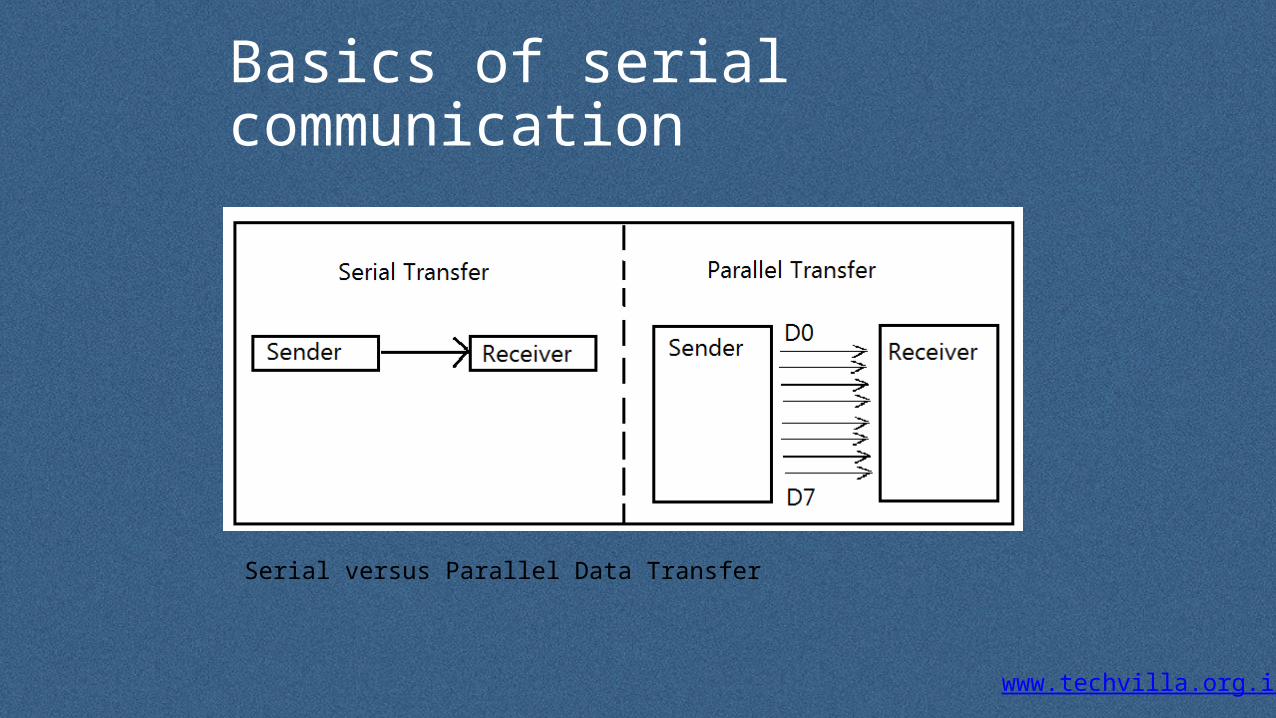
Basics of serial communication
Serial versus Parallel Data Transfer

www.techvilla.org.in
UART
• RS232 standard and application, e.g.
43
RS232 port(UART)
RS232 port (UART)
RS232 standard3 wires+10 V=‘0’=SPACE-10V=‘1’=MARK
Pin2Pin3pin5
Pin3Pin2pin5

www.techvilla.org.in
U Universal A Asynchronous R Receiver T Transmitter
UART for data communication
• Serial data transmission means sending data bits one by one using one wire.
• Asynchronous transmission means a data (including one start bit , 8-bit data, and stop bits) can be sent at any time.
54
www.techvilla.org.in
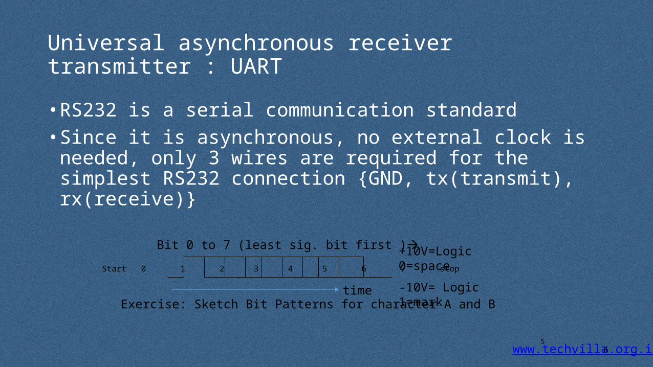
Universal asynchronous receiver transmitter : UART
• RS232 is a serial communication standard• Since it is asynchronous, no external clock is needed, only 3 wires are
required for the simplest RS232 connection {GND, tx(transmit), rx(receive)}
65
+10V=Logic 0=space
-10V= Logic 1=mark
Exercise: Sketch Bit Patterns for character A and B
Start 0 1 2 3 4 5 6 7 stop
Bit 0 to 7 (least sig. bit first )
time
www.techvilla.org.inCEG2400 Ch6. Serial Interface -- UART V4b
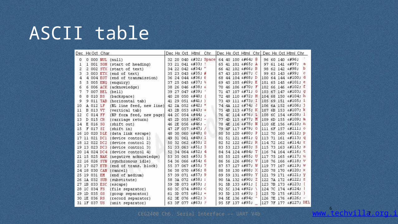
ASCII table
76
www.techvilla.org.inCEG2400 Ch6. Serial Interface -- UART V4b
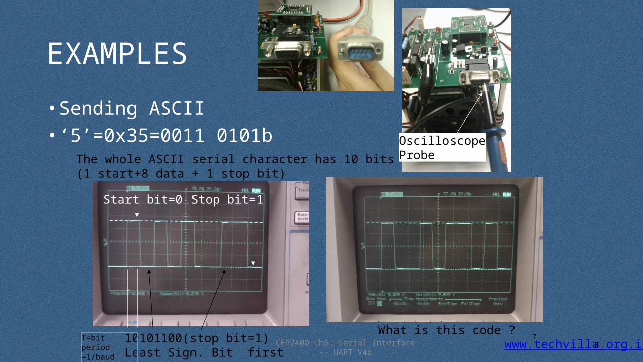
EXAMPLES
• Sending ASCII • ‘5’=0x35=0011 0101b
87
Start bit=0
10101100(stop bit=1)Least Sign. Bit first
What is this code ?
The whole ASCII serial character has 10 bits (1 start+8 data + 1 stop bit)
Stop bit=1
OscilloscopeProbe
T=bit period =1/baud rate
www.techvilla.org.inCEG2400 Ch6. Serial Interface -- UART V4b
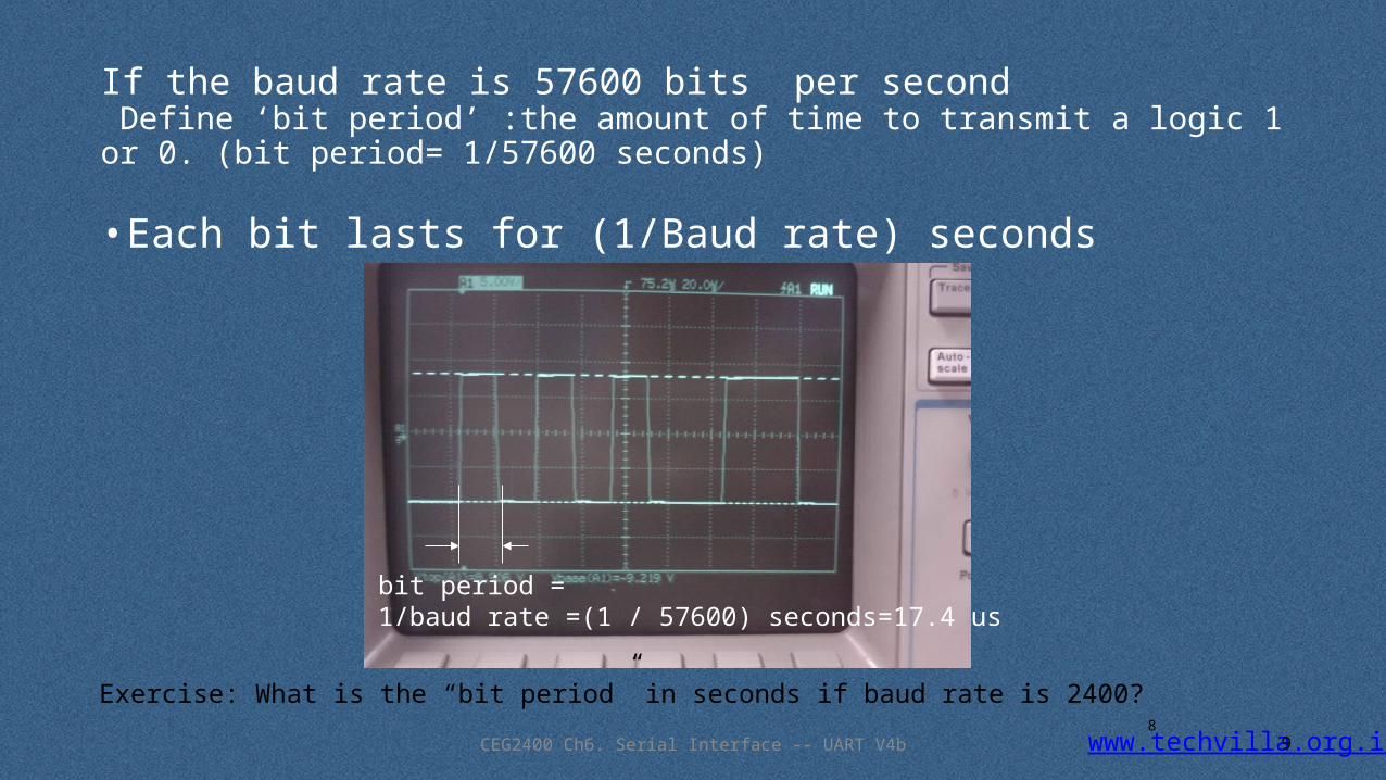
If the baud rate is 57600 bits per second Define ‘bit period’ :the amount of time to transmit a logic 1 or 0. (bit period= 1/57600 seconds)
• Each bit lasts for (1/Baud rate) seconds
98
bit period =1/baud rate =(1 / 57600) seconds=17.4 us
Exercise: What is the “bit period” in seconds if baud rate is 2400?

www.techvilla.org.in
Asynchronous Serial Communication• With asynchronous communication, the transmitter and
receiver do not share a common clock
Transmitter Receiver+
1 byte-wide Data
Data–
1 byte-wide Data
The Receiver
Extracts the data using its own clock
Converts the serial data back to the parallel form after stripping off the start, stop and parity bits
The Transmitter
Shifts the parallel data onto the serial line using its own clock
Also adds the start, stop and parity check bits
Add: Start, Stop, Parity Bits Remove: Start, Stop, Parity Bits
www.techvilla.org.in
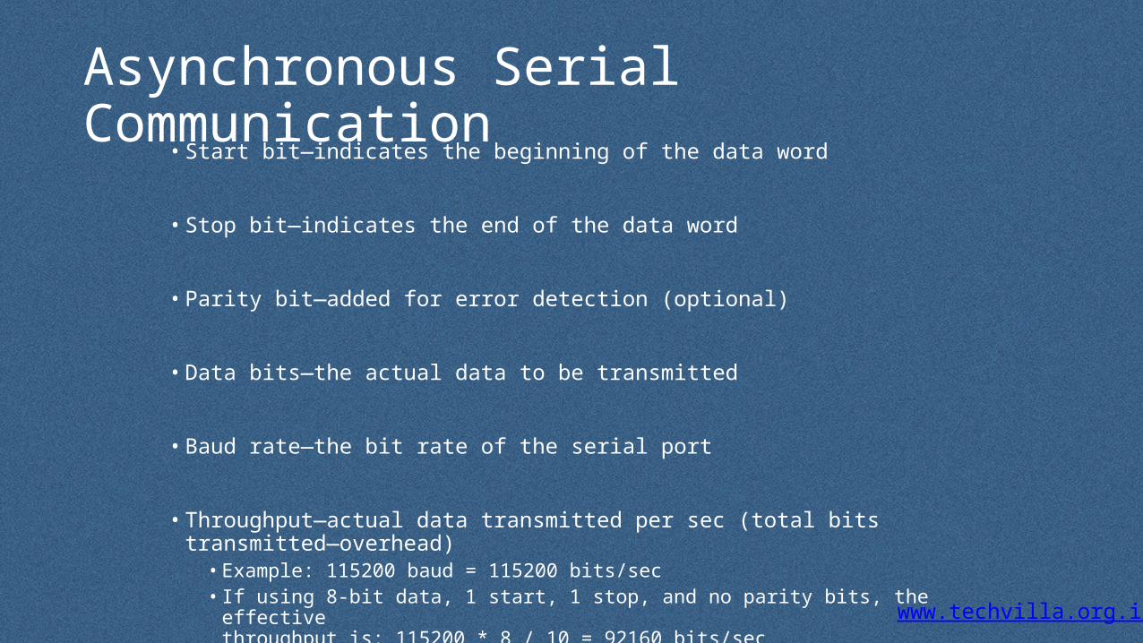
Asynchronous Serial Communication• Start bit—indicates the beginning of the data word
• Stop bit—indicates the end of the data word
• Parity bit—added for error detection (optional)
• Data bits—the actual data to be transmitted
• Baud rate—the bit rate of the serial port
• Throughput—actual data transmitted per sec (total bits transmitted—overhead)• Example: 115200 baud = 115200 bits/sec• If using 8-bit data, 1 start, 1 stop, and no parity bits, the effective
throughput is: 115200 * 8 / 10 = 92160 bits/sec

www.techvilla.org.in
Asynchronous Serial Communication
• Asynchronous transmission is easy to implement but less efficient as it requires an extra 2-3 control bits for every 8 data bits
• This method is usually used for low volume transmission

www.techvilla.org.in
Synchronous Serial Communication• In the synchronous mode, the transmitter and receiver share a common clock
• The transmitter typically provides the clock as a separate signal in addition to the serial data
Transmitter Receiver
Data
Clock
The Receiver Extracts the data using
the clock provided by the transmitter
Converts the serial data back to the parallel form
The Transmitter Shifts the data onto the serial
line using its own clock
Provides the clock as a separate signal
No start, stop, or parity bits added to data
1 byte-wide Data 1 byte-wide Data
www.techvilla.org.in
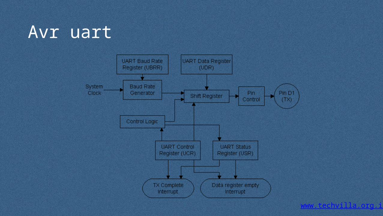
Avr uart
www.techvilla.org.in
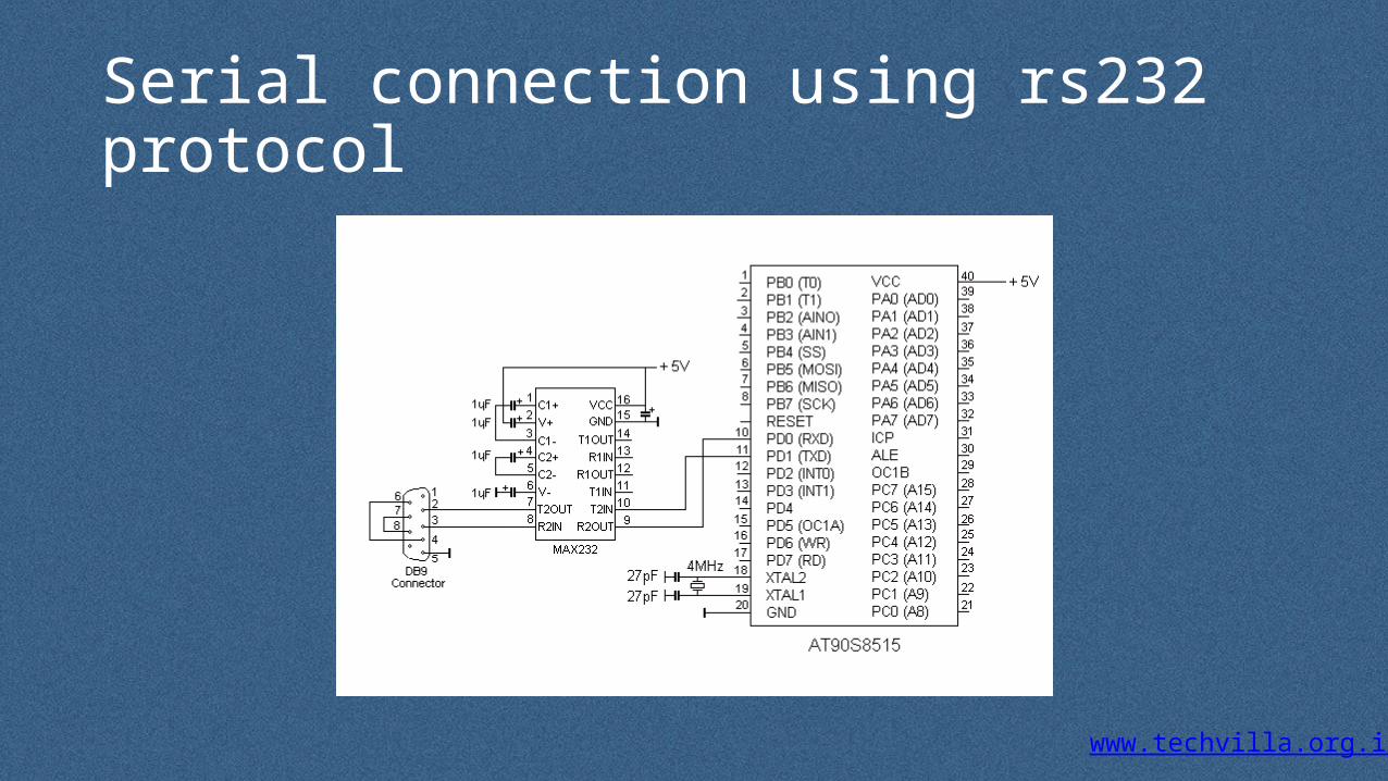
Serial connection using rs232 protocol

www.techvilla.org.in
RS232
• For asynchronous communication.• between two data serial links on a network ─Between a data
communication equipment and data terminal equipment.• RS232C ─a standard protocol used in IBM PC COM ports, keyboard,
computer-mice and • For the data serial link network in UART bit format
www.techvilla.org.in
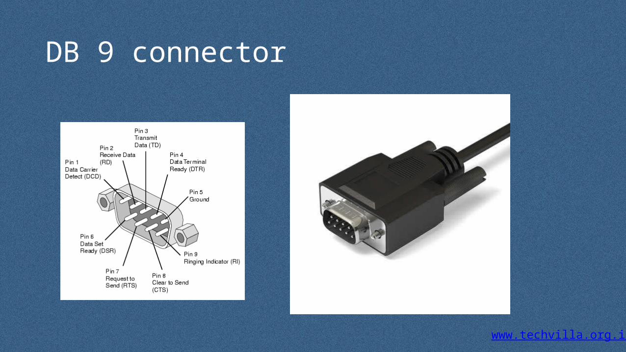
DB 9 connector

www.techvilla.org.in
Max 232 ic
www.techvilla.org.in
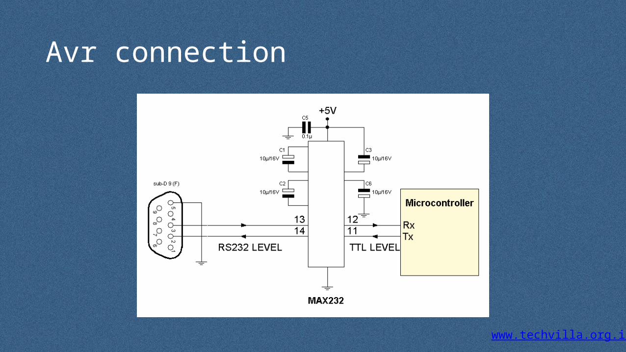
Avr connection

www.techvilla.org.in
How to set-up avr UART
• The first step is to set the baud rate in both, the master and the slave. The baud rate has to be the same for both – master and slave.
• Set the number of data bits, which needs to be sent.• Get the buffer ready! In case of transmission (from AVR to some other
device), load it up with the data to be sent, whereas in case of reception, save the previous data so that the new received data can be overwritten onto it.
• Then enable the transmitter/receiver according to the desired usage.

www.techvilla.org.in
• in UART, there is no master or slave since master is defined by the MicroController, which is responsible for clock pulse generation.
• Master and Slave terms occur only in the case of USART.• Master µC is the one which is responsible for Clock pulse generation
on the Bus.
www.techvilla.org.in
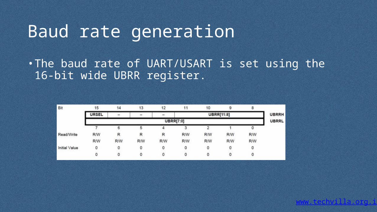
Baud rate generation
• The baud rate of UART/USART is set using the 16-bit wide UBRR register.

www.techvilla.org.in
UBRR register
• he 16-bit UBRR register is comprised of two 8-bit registers – UBRRH (high) and UBRRL (low).
• The USART Baud Rate Register (UBRR) and the down-counter connected to it functions as a programmable prescaler or baud rate generator.
• The down-counter, running at system clock (FOSC), is loaded with the UBRR value each time the counter has counted down to zero or when the UBRRL Register is written.
• A clock is generated each time the counter reaches zero.

www.techvilla.org.in
Calculating baud rate and UBRR value

www.techvilla.org.in
•BAUD = Baud Rate in Bits/Second (bps) •Bps = Bytes/Second, whereas bps = Bits/Second)•FOSC = System Clock Frequency (1MHz) (or as per use in case of external oscillator) •UBRR = Contents of UBRRL and UBRRH registers

www.techvilla.org.in
Uart data Frame
www.techvilla.org.in
FRAME STRUCTURE
• USART communication uses special protocol to transmit data reliable. It consists of several parts:
• 1 start bit;• 5,6,7,8 or 9 data bits;• no, even, or odd parity bit;• 1 or 2 stop bits.