serial ata flash drive - prog.apacer.comprog.apacer.com/usdownload/safd25m2_ht_ds.pdf · apacer’s...
TRANSCRIPT

RoHS Compliant
Serial ATA Flash Drive Datasheet for SAFD25M2
January 14, 2011
Version 1.4
Apacer Technology Inc. 4th Fl., 75 Xintai 5th Rd., Sec.1, Hsichih, New Taipei City, Taiwan 221
Tel: +886-2-2698-2888 Fax: +886-2-2698-2889
www.apacer.com

Serial ATA Flash Drive AP-SAFD25MPAxxxxS-HT
1 © 2011 Apacer Technology Inc. Rev. 1.4
Features:
� Standard Serial ATA 2.6 (Gen. 2) – Serial ATA 2.6 (Gen. 2) – SATAⅡ, 3.0 Gbps – ATA-compatible command set
� Capacities – 1, 2, 4, 8, and 16 GB
� Performance* – Burst read/write: 300 MB/sec – Sustained read: up to 100 MB/sec – Sustained write: up to 88 MB/sec
� Intelligent endurance design – Built-in hardware BCH ECC, correcting
8-bit or 15-bit error per 512-byte data sector
– Static wear-leveling scheme together with dynamical block allocation to significantly increase the lifetime of a flash device and optimize the disk performance
– Flash bad-block management – S.M.A.R.T. – Power Failure Management – Quick Erase
� NAND Flash Type: SLC
� Data integrity under power-cycling – No battery required for data storage
� Temperature – 0°C to 70°C for operating – -40°C to 100°C for storage
� Supply voltage – 5.0 V ± 5%
� Low power consumption* – Active mode: 260 mA (5.0 V) – Idle mode: 130 mA (5.0 V)
� Form factor – 2.5 inch
� Connector – 7-pin SATA male connector – 15-pin SATA power connector
� RoHS compliant
*Varies from capacities.

Serial ATA Flash Drive AP-SAFD25MPAxxxxS-HT
2 © 2011 Apacer Technology Inc. Rev. 1.4
Table of Contents
1. Product Description ............................ ..................................................................... 4
1.1 Introduction ....................................... ........................................................................................... 4
1.2 Functional Block Diagram........................... ................................................................................ 4
1.3 ATA Mode Support................................... .................................................................................... 5
1.4 Capacity Specification............................. .................................................................................... 5
1.5 Performance ........................................ ......................................................................................... 5
1.5 Pin Assignments .................................... ...................................................................................... 6
2. Software Interface ............................. ....................................................................... 8
2.1 Command Set ........................................ ....................................................................................... 8 2.1.1 Check Power Mode (E5h) .............................................................................................. 10 2.1.2 Execute Diagnostics (90h) ............................................................................................. 10 2.1.3 Flush Cache (E7h) ......................................................................................................... 10 2.1.4 Identify Device (ECh) ..................................................................................................... 10 2.1.5 Idle (E3h)........................................................................................................................ 18 2.1.6 Idle Immediate (E1h)...................................................................................................... 18 2.1.7 Initialize Drive Parameters (C8h) ................................................................................... 18 2.1.8 Read DMA (C8h)............................................................................................................ 19 2.1.9 Read Multiple (C4h) ....................................................................................................... 19 2.1.10 Read Sector(s) (20h)...................................................................................................... 19 2.1.11 Read Verify Sector(s) (40h) ........................................................................................... 19 2.1.12 Recalibrate (10h)............................................................................................................ 19 2.1.13 Security Disable Password (F6h)................................................................................... 19 2.1.14 Security Erase Prepare (F3h) ........................................................................................ 19 2.1.15 Security Erase Unit (F4h)............................................................................................... 19 2.1.16 Security Freeze Lock (F5h)............................................................................................ 20 2.1.17 Security Set Password (F1h) ......................................................................................... 20 2.1.18 Security Unlock (F2h)..................................................................................................... 20 2.1.19 Seek (7xh) ...................................................................................................................... 20 2.1.20 Set Features (EFh)......................................................................................................... 20 2.1.21 Set Multiple Mode (C6h) ................................................................................................ 20 2.1.22 Sleep (E6h) .................................................................................................................... 20 2.1.23 SMART (B0h) ................................................................................................................. 21 2.1.24 Standby (E2h) ................................................................................................................ 23 2.1.25 Standby Immediate (E0h) .............................................................................................. 23 2.1.26 Write DMA (CAh) ........................................................................................................... 24 2.1.27 Write Multiple (C5h) ....................................................................................................... 24 2.1.28 Write Sector(s) (30h)...................................................................................................... 24
2.2 S.M.A.R.T..................................................................................................................................... 25
3. Flash Management ............................... .................................................................. 26
3.1 Error Correction/Detection......................... ............................................................................... 26
3.2 Bad Block Management............................... .............................................................................. 26
3.3 Wear Leveling ...................................... ....................................................................................... 26

Serial ATA Flash Drive AP-SAFD25MPAxxxxS-HT
3 © 2011 Apacer Technology Inc. Rev. 1.4
3.4 Power Failure Management........................... ............................................................................ 26
3.5 Quick Erase........................................ ......................................................................................... 26
4. Environmental Specifications ................... ............................................................ 27
4.1 Environments ....................................... ...................................................................................... 27
5. Electrical Specification ........................ ................................................................... 28
6. Physical Characteristics........................ ................................................................. 29
6.1 Dimension .......................................... ......................................................................................... 29
7. Product Ordering Information.................... ............................................................ 31
7.1 Product Code Designations .......................... ............................................................................ 31
7.2 Valid Combinations................................. ................................................................................... 32

Serial ATA Flash Drive AP-SAFD25MPAxxxxS-HT
4 © 2011 Apacer Technology Inc. Rev. 1.4
1. Product Description
1.1 Introduction
Apacer’s Serial ATA Flash Drive (SAFD25M2) is a solid-state disk (SSD) drive that contains a controller, embedded firmware, and flash media along with a male connector. Using NAND flash memory devices, the SAFD25M2 drive interfaces with the host allowing data to be seamlessly transferred between the host and the flash devices.
The SAFD25M2 drive is designed with a single-chip controller, offering capacities of up to 16 gigabytes and providing full support for the SATAⅡ high-speed interface standard. It can operate at sustained access rates of up to 100 megabytes per second, which is much faster than any other solid-state or traditional SATA drive currently available on the market.
In addition to buffer management through dynamical allocation, the SAFD25M2 adopts the static wear-leveling scheme to allow uniform use of all storage blocks, ensuring that the lifetime of a flash media can be significantly increased and the disk performance is optimized as well. The SAFD25M2 provides the S.M.A.R.T. feature complies to the SATA Rev.2.6, ATA/ATAPI-7 specifications and uses the standard SMART command B0h to read data from the drive. This feature protects the user from unscheduled downtime by monitoring and storing critical drive performance.
1.2 Functional Block Diagram
The SAFD25M2 drive includes a single-chip SATAⅡ Controller and the flash media, as well as the SATA standard interface. The controller integrates the flash management unit with the controller itself to support multi-channel, multi-bank flash arrays. Figure 1-1 shows the functional block diagram.
Figure 1-1 Apacer SAFD25M2 block diagram

Serial ATA Flash Drive AP-SAFD25MPAxxxxS-HT
5 © 2011 Apacer Technology Inc. Rev. 1.4
1.3 ATA Mode Support
The SAFD25M2 provides ATA mode support as follows:
� Up to PIO mode-4 � Up to Multiword DMA mode-2 � Up to UDMA mode-5
1.4 Capacity Specification
Capacity specification of the SAFD product family is available as shown in Table 1-1. It lists the specific capacity, the default numbers of logical cylinders and heads, and the number of logical sectors per track for each product line.
Table 1-1 Capacity specification
Capacity Total Bytes Cylinders Heads Sectors Max LBA
1 GB 992,968,704 1,924 16 63 1,939,392
2 GB 2,002,452,480 3,880 16 63 3,911,040
4 GB 4,021,936,128 7793 16 63 7,855,344
8 GB 8,061,419,520 15620 16 63 15,744,960
16 GB 16,139,681,792 16383 16 63 31,522,816 *Cylinders, heads or sectors are not applicable for these capacities. Only LBA addressing applies.
1.5 Performance
Performance of the SAFD25M2 is shown in Table 1-2.
Table 1-2 Performance specification
Capacity
Performance 1 GB 2 GB 4 GB 8 GB 16 GB
Sustained read (MB/s) 42 52 100 100 100
Sustained write (MB/s) 17 22 46 88 88
Note: Performances vary from different flash configurations.

Serial ATA Flash Drive AP-SAFD25MPAxxxxS-HT
6 © 2011 Apacer Technology Inc. Rev. 1.4
1.5 Pin Assignments
Figure 1-2 illustrates pin assignments of Apacer SAFD25M2 pins, and Table1-3 and Table 1-4 describe its signal segment and power segment, respectively.
Figure 1-2 Apacer SAFD25M2 pin assignments
Table 1-3 Signal segment Table 1-4 Power segment
Name Type Description
Pin Signal/Description
S1 GND
P1 Not used (3.3V)
S2 RxP + Differential Receive Signal
P2 Not used (3.3V)
S3 RxN - Differential Receive Signal
P3 Not used (3.3V)
S4 GND
P4 Ground
S5 TxN - Differential Transmit Signal
P5 Ground
S6 TxP +Differential Transmit Signal
P6 Ground
S7 GND
P7 5V
P8 5V
P9 5V
P10 Ground
P11 Ground
P12 Ground
P13 Not used (12V)
P14 Not used (12V)
P15 Not used (12V)

Serial ATA Flash Drive AP-SAFD25MPAxxxxS-HT
7 © 2011 Apacer Technology Inc. Rev. 1.4
Figure 1-3 SATA Cable/Connector Connection Diagram
The connector on the left represents the Host with TX/RX differential pairs connected to a cable. The connector on the right shows the Device with TX/RX differential pairs also connected to the cable. Notice also the ground path connecting the shielding of the cable to the Cable Receptacle.

Serial ATA Flash Drive AP-SAFD25MPAxxxxS-HT
8 © 2011 Apacer Technology Inc. Rev. 1.4
2. Software Interface
2.1 Command Set
Table 2-1 summarizes the ATA commands supported by the SAFD25M2.
Table 2-1 Command set (1 of 2)
Command Code FR1 SC2 SN3 CY4 DH5 LBA 6
Check-Power-Mode E5H - - - - D8 -
Execute-Drive-Diagnostic 90H - - - - D -
Flush-Cache E7H - - - - D -
Identify-Drive ECH - - - - D -
Idle E3H - Y - - D -
Idle-Immediate E1H - - - - D -
Initialize-Drive-Parameters 91H - Y - - Y -
Read-DMA C8H or C9H - Y Y Y Y Y
Read-Multiple C4H - Y Y Y Y Y
Read-Sector(s) 20H or 21H - Y Y Y Y Y
Read-Verify-Sector(s) 40H or 41H - Y Y Y Y Y
Recalibrate 10H - - - - D -
Security-Disable-Password F6H - - - - D -
Security-Erase-Prepare F3H - - - - D -
Security-Erase-Unit F4H - - - - D -
Security-Freeze-Lock F5H - - - - D -
Security-Set-Password F1H - - - - D -
Security-Unlock F2H - - - - D -
Seek 7XH - - Y Y
Set-Features EFH Y7 - - - D -

Serial ATA Flash Drive AP-SAFD25MPAxxxxS-HT
9 © 2011 Apacer Technology Inc. Rev. 1.4
Table 2-1 Command set (2 of 2)
Command Code FR1 SC2 SN3 CY4 DH5 LBA 6
Set-Multiple-Mode C6H - Y - - D -
Sleep E6H - - - - D -
SMART B0H Y Y Y Y D
Standby E2H - - - - D -
Standby-lmmediate E0H - - - - D -
Write-DMA CAH - Y Y Y Y Y
Write-Multiple C5H - Y Y Y Y Y
Write-Sector(s) 30H - Y Y Y Y Y 1. FR - Features register 2. SC - Sector Count register 3. SN - Sector Number register 4. CY - Cylinder registers 5. DH - Drive/Head register 6. LBA - Logical Block Address mode supported (see command descriptions for use) 7. Y - The register contains a valid parameter for this command. 8. For the Drive/Head register:
Y means both the SAFD and Head parameters are used D means only the SAFD parameter is valid and not the Head parameter

Serial ATA Flash Drive AP-SAFD25MPAxxxxS-HT
10 © 2011 Apacer Technology Inc. Rev. 1.4
2.1.1 Check Power Mode (E5h) The host can use this command to determine the current power management mode.
2.1.2 Execute Diagnostics (90h) This command performs the internal diagnostic tests implemented by the drive. See ERROR register for diagnostic codes.
2.1.3 Flush Cache (E7h) This command is used by the host to request the device to flush the write cache. If there is data in the write cache, that data shall be written to the media. The BSY bit shall remain set to one until all data has been successfully written or an error occurs.
2.1.4 Identify Device (ECh) This command read out 512 Bytes of drive parameter information. Parameter information consists of the arrangement and value as shown in the following table. This command enables the host to receive the Identify Drive Information from the device.
Identify Device Information Default Value (1/9)
Word Value F/V Description
0
0040h
F
X
F
X
X
F
X
F
General configuration bit-significant information:
15 0 = ATA device
14-8 Retired
7 1 = removable media device
6 Obsolete
5-3 Retired
2 Reserved
1 Retired
0 Reserved
1 XXXXh X Number of logical cylinders
2 C837h V Specific configuration
3 00XXh X Number of logical heads
4-5 XXXXh X Retired
6 XXXXh X Number of logical sector per logical track
7-8 XXXXh V Reserved for assignment by the Compact Flash Association
9 000Eh X Retired
10-19 XXXXh F Serial number (20 ASCII characters)
20-21 XXXXh X Retired

Serial ATA Flash Drive AP-SAFD25MPAxxxxS-HT
11 © 2011 Apacer Technology Inc. Rev. 1.4
Identify Device Information Default Value (2/9)
Word Value F/V Description
22 003Fh X Obsolete
23-26 XXXXh F Firmware revision (8 ASCII characters)
27-46 XXXXh F Model number (40 ASCII characters)
47
8000h
F
F
F
15-8 80h
7-0 00h = Reserved
01h = Maximum number of 1 sector on READ/WRITE MULTIPLE commands
48 4000h F Reserved
49
2F00h
F
F
F
F
F
F
F
X
Capabilities
15-14 Reserved for the IDENTIFY PACKET DEVICE command
13 1 = Standby timer values as specified in this standard are supported.
0 = Standby timer values shall be managed by the device.
12 Reserved for the IDENTIFY PACKET DEVICE command
11 1 = IORDY supported
0 = IORDY may be supported
10 1 = IORDY may be disabled
9 1 = LBA supported
8 1 = DMA supported
7-0 Retired
50
4000h
F
F
F
X
F
Capabilities
15 Shall be cleared to zero
14 Shall be set to one
13-2 Reserved
1 Obsolete
0 Shall be set to one to indicate a device specific Standby timer value minimum
51 0280h X 15-8 PIO data transfer cycle timing mode
7-0 Reserved
52 0000h X Obsolete

Serial ATA Flash Drive AP-SAFD25MPAxxxxS-HT
12 © 2011 Apacer Technology Inc. Rev. 1.4
Identify Device Information Default Value (3/9)
Word Value F/V Description
53
0007h
F
F
F
X
15-3 Reserved
2 1 = the fields reported in word 88 are valid
0 = the fields reported in word 88 are not valid
1 1 = the fields reported in word 70:64 are valid
0 = the fields reported in word 70:64 are not valid
0 1 = the fields reported in word 58:54 are valid
0 = the fields reported in word 58:54 are not valid
54 XXXXh X Number of current cylinders
55 00XXh X Number of current heads
56 XXXXh X Number of current sector per track
57-58 XXXXh X Current capacity in sectors
59
0000h
F
V
V
15-9 Reserved
8 1 = Multiple sector setting is valid
7-0 xxh = Setting for number of sectors that shall be transferred per interrupt on R/W Multiple command
60-61 XXXXh F Total number of user addressable sectors
62 0000h X Obsolete
63
0007h
F
V
V
V
F
F
F
F
15-11 Reserved
10 1 = Multiword DMA mode 2 is selected
0 = Multiword DMA mode 2 is not selected
9 1 = Multiword DMA mode 1 is selected
0 = Multiword DMA mode 1 is not selected
8 1 = Multiword DMA mode 0 is selected
0 = Multiword DMA mode 0 is not selected
7-3 Reserved
2 1 = Multiword DMA mode 2 and below are supported
1 1 = Multiword DMA mode 1 and below are supported
0 1 = Multiword DMA mode 0 and below are supported

Serial ATA Flash Drive AP-SAFD25MPAxxxxS-HT
13 © 2011 Apacer Technology Inc. Rev. 1.4
Identify Device Information Default Value (4/9)
Word Value F/V Description
64 0003h F
F
15-8 Reserved
7-0 Advanced PIO modes supported
65 0078h F Minimum Multiword DMA transfer cycle time per word
66 0078h F Manufacturer’s recommended Multiword DMA transfer cycle time
67 0078h F Minimum PIO transfer cycle time without flow control
68 0078h F Minimum PIO transfer cycle time with IORDY flow control
69-79 0000h F Reserved (for future command overlap and queuing)
80
01FEh
F
F
F
F
F
F
F
F
F
F
F
F
F
X
X
F
Major version number 0000h or FFFFh = device does not report version
15 Reserved
14 Reserved for ATA/ATAPI-14
13 Reserved for ATA/ATAPI-13
12 Reserved for ATA/ATAPI-12
11 Reserved for ATA/ATAPI-11
10 Reserved for ATA/ATAPI-10
9 Reserved for ATA/ATAPI-9
8 Reserved for ATA/ATAPI-8
7 1 = supports ATA/ATAPI-7
6 1 = supports ATA/ATAPI-6
5 1 = supports ATA/ATAPI-5
4 1 = supports ATA/ATAPI-4
3 Obsolete
2 Obsolete
1 Obsolete
0 Reserved
81 0021h F Minor version number

Serial ATA Flash Drive AP-SAFD25MPAxxxxS-HT
14 © 2011 Apacer Technology Inc. Rev. 1.4
Identify Device Information Default Value (5/9)
Word Value F/V Description
82
0068h
X
F
F
F
X
F
F
F
F
F
F
F
F
F
F
F
Command set supported
15 Obsolete
14 1 = NOP command supported
13 1 = READ BUFFER command supported
12 1 = WRITE BUFFER command supported
11 Obsolete
10 1 = Host Protected Area feature set supported
9 1 = DEVICE RESET command supported
8 1 = SERVICE interrupt supported
7 1 = release interrupt supported
6 1 = look-ahead supported
5 1 = write cache supported
4 Shall be cleared to zero to indicate that the PACKET Command feature set is not supported
3 1 = mandatory Power Management feature set supported
2 1 = Removable Media feature set supported
1 1 = Security Mode feature set supported
0 1 = SMART feature set supported
83
5000h
F
F
F
F
F
F
F
F
F
F
F
F
Command set supported
15 Shall be cleared to zero
14 Shall be set to one
13-9 Reserved
8 1 = SET MAX security extension supported
7 Reserved
6 1 = SET FEATURES subcommand required to spin-up after power-up
5 1 = Power-Up In Standby feature set supported
4 1 = Removable Media Status Notification feature set supported
3 1 = Advanced Power Management feature set supported
2 1 = CFA feature set supported
1 1 = READ/WRITE DMA QUEUED supported
0 1 = DOWNLOAD MICROCODE command supported

Serial ATA Flash Drive AP-SAFD25MPAxxxxS-HT
15 © 2011 Apacer Technology Inc. Rev. 1.4
Identify Device Information Default Value (6/9)
Word Value F/V Description
84
4000h
F
F
F
F
F
Command set/feature supported extension
15 Shall be cleared to zero
14 Shall be set to one
13-2 Reserved
1 1 = SMARAT self-test supported
0 1 = SMARAT error logging supported
85
0008h
X
F
F
F
X
V
F
V
V
V
V
F
F
F
V
V
Command set/feature enabled
15 Obsolete
14 1 = NOP command enabled
13 1 = READ BUFFER command enabled
12 1 = WRITE BUFFER command enabled
11 Obsolete
10 1 = Host Protected Area feature set enabled
9 1 = DEVICE RESET command enabled
8 1 = SERVICE interrupt enabled
7 1 = release interrupt enabled
6 1 = look-ahead enabled
5 1 = write cache enabled
4 Shall be cleared to zero to indicate that the PACKET Command feature set is not supported
3 1 = mandatory Power Management feature set enabled
2 1 = Removable Media feature set enabled
1 1 = Security Mode feature set enabled
0 1 = SMART feature set enabled

Serial ATA Flash Drive AP-SAFD25MPAxxxxS-HT
16 © 2011 Apacer Technology Inc. Rev. 1.4
Identify Device Information Default Value (7/9)
Word Value F/V Description
86
5000h
F
F
F
F
F
F
F
F
Command set/feature enabled
15-9 Reserved
8 1 = SET MAX security extension enabled by SET MAX SET PASSWORD
7 See Address Offset Reserved Area Boot, INCITS TR27:2001
6 1 = SET FEATURES subcommand required to spin-up after power-up
5 1 = Power-Up In Standby feature set enabled
4 1 = Removable Media Status Notification feature set enabled
3-1 1 = Advanced Power Management feature set enabled
0 1 = DOWNLOAD MICROCODE command supported
87
4000h
F
F
F
F
F
Command set/feature default
15 Shall be cleared to zero
14 Shall be set to one
13-2 Reserved
1 1 = SMARAT self-test supported
0 1 = SMARAT error logging supported

Serial ATA Flash Drive AP-SAFD25MPAxxxxS-HT
17 © 2011 Apacer Technology Inc. Rev. 1.4
Identify Device Information Default Value (8/9)
Word Value F/V Description
88
203Fh
V
V
V
V
V
F
F
F
F
F
F
15-13 Reserved
12 1 = Ultra DMA mode 4 is selected
0 = Ultra DMA mode 4 is not selected
11 1 = Ultra DMA mode 3 is selected
0 = Ultra DMA mode 3 is not selected
10 1 = Ultra DMA mode 2 is selected
0 = Ultra DMA mode 2 is not selected
9 1 = Ultra DMA mode 1 is selected
0 = Ultra DMA mode 1 is not selected
8 1 = Ultra DMA mode 0 is selected
0 = Ultra DMA mode 0 is not selected
7-5 Reserved
4 1 = Ultra DMA mode 4 and below are supported
3 1 = Ultra DMA mode 3 and below are supported
2 1 = Ultra DMA mode 2 and below are supported
1 1 = Ultra DMA mode 1 and below are supported
0 1 = Ultra DMA mode 0 and below are supported
89 0000h F Time required for security erase unit completion
90 0000h F Time required for Enhanced security erase completion
91 0000h V Current advanced power management value
92 0000h V Master Password Revision Code
93 0000h X Hardware reset result
94-126 0000h V Reserved
127
0000h
F
F
Removable Media Status Notification feature set support
15-2 Reserved
1-0 00 = Removable Media Status Notification feature set not supported
01 = Removable Media Status Notification feature set supported
10 = Reserved
11 = Reserved

Serial ATA Flash Drive AP-SAFD25MPAxxxxS-HT
18 © 2011 Apacer Technology Inc. Rev. 1.4
Identify Device Information Default Value (9/9)
Word Value F/V Description
128
0001h
F
V
F
F
V
V
V
V
F
Security status
15-9 Reserved
8 Security level 0 = High, 1 = Maximum
7-6 Reserved
5 1 = Enhanced security erase supported
4 1 = Security count expired
3 1 = Security frozen
2 1 = Security locked
1 1 = Security enabled
0 1 = Security supported
129-159 0000h X Vendor specific
160-254 0000h X Reserved
255
0000h
X
Integrity word
15-8 Checksum
7-0 Signature
Key:
F/V = Fixed/variable content
F = the content of word is fixed and does not change. For removable media devices, these values may change when media is removed or changed.
V = the contents of the word is variable and may change depending on the state of the device or the commands executed by the device.
X = the content of the word may be fixed or variable.
2.1.5 Idle (E3h) This command causes the device to set BSY, enter the Idle mode, clear BSY and generate an interrupt. If sector count is non-zero, the automatic power down mode is enabled. If the sector count is zero, the automatic power mode is disabled.
2.1.6 Idle Immediate (E1h) This command causes the device to set BSY, enter the Idle(Read) mode, clear BSY and generate an interrupt.
2.1.7 Initialize Drive Parameters (C8h) This command enables the host to set the number of sectors per track and the number of tracks per heads.

Serial ATA Flash Drive AP-SAFD25MPAxxxxS-HT
19 © 2011 Apacer Technology Inc. Rev. 1.4
2.1.8 Read DMA (C8h) Read data from sectors during Ultra DMA and Multiword DMA transfer. Use the SET FEATURES command to specify the mode value. A sector count of zero requests 256 sectors.
2.1.9 Read Multiple (C4h) This command performs similarity to the Read Sectors command. Interrupts are not generated on each sector, but on the transfer of a block which contains the number of sectors defined by a Set Multiple command.
2.1.10 Read Sector(s) (20h) This command reads 1 to 256 sectors as specified in the Sector Count register from sectors which is set by Sector number register. A sector count of zero requests 256 sectors. The transfer beings specified in the Sector Number register.
2.1.11 Read Verify Sector(s) (40h) This command verifies one or more sectors on the drive by transferring data from the flash media to the data buffer in the drive and verifying that the ECC is correct. This command is identical to the Read Sectors command, except the DRQ is never set and no data is transferred to the host.
2.1.12 Recalibrate (10h) The current drive performs no processing if it receives this command. It is supported for backward compatibility with previous devices.
2.1.13 Security Disable Password (F6h) Disables any previously set user password and cancels the lock. The host transfers 512 bytes of data, as shown in the following table, to the drive. The transferred data contains a user or master password, which the drive compares with the saved password. If they match, the drive cancels the lock. The master password is still saved. It is re-enabled by issuing the SECURITY SET PASSWORD command to reset a user password.
2.1.14 Security Erase Prepare (F3h) This command shall be issued immediately before the Security Erase Unit command to enable erasing and unlocking. This command prevents accidental loss of data on the drive.
2.1.15 Security Erase Unit (F4h) The host uses this command to transfer 512 bytes of data, as shown in the following table, to the drive. The transferred data contains a user or master password, which the drive compares with the saved password. If they match, the drive deletes user data, disables the user password, and cancels the locks. The master password is still saved. It is re-enabled by issuing the SECURITY SET PASSWORD command to reset a user password.

Serial ATA Flash Drive AP-SAFD25MPAxxxxS-HT
20 © 2011 Apacer Technology Inc. Rev. 1.4
2.1.16 Security Freeze Lock (F5h) Causes the drive to enter Frozen mode. Once this command has been executed, the following commands to update a lock result in the Aborted Command error:
� SECURITY SET PASSWORD
� SECURITY UNLOCK
� SECURITY DISABLE PASSWORD
� SECURITY ERASE PREPARE
� SECURITY ERASE UNIT
The drive exits from Frozen mode upon a power-off or hard reset. If the SECURITY FREEZE LOCK command is issued when the drive is placed in Frozen mode, the drive executes the command, staying the Frozen mode.
2.1.17 Security Set Password (F1h) This command sets user password or master password. The host outputs sector data with PIO data-out protocol to indicate the information defined in the following table.
2.1.18 Security Unlock (F2h) This command disables LOCKED MODE of the device. This command transfers 512 byte of data from the host with PIO data-out protocol. The following table defines the content of this information.
2.1.19 Seek (7xh) This command is effectively a NOP command to the device although it does perform a range check.
2.1.20 Set Features (EFh) This command set parameter to Features register and set drive’s operation. For transfer mode, parameter is set to Sector Count register. This command is used by the host to establish or select certain features.
Features register Value and settable operating mode
Value Function 02h Enable write cache 03h Set transfer mode based on value in Sector Count register. 55h Disable read look-ahead feature 82h Disable write cache AAh Enable read look-ahead feature
2.1.21 Set Multiple Mode (C6h) This command enables the device to perform READ MULTIPLE and WRITE MULTIPLE operations and establishes the block count for these commands.
2.1.22 Sleep (E6h) This command causes the device to set BSY, enter the Sleep mode, clear BSY and generate an interrupt.
Serial ATA Flash Drive AP-SAFD25MPAxxxxS-HT
21 © 2011 Apacer Technology Inc. Rev. 1.4
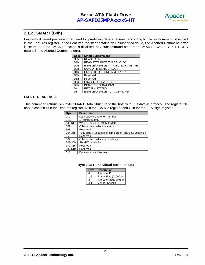
2.1.23 SMART (B0h) Performs different processing required for predicting device failures, according to the subcommand specified in the Features register. If the Features register contains an unsupported value, the Aborted Command error is returned. If the SMART function is disabled, any subcommand other than SMART ENABLE OPERTIONS results in the Aborted Command error.
Code Smart Subcommand D0h READ DATA D1h READ ATTRIBUTE THRESHOLDS D2h ENABLE/DISABLE ATTRIBUTE AUTOSAVE D3h SAVE ATTRIBUTE VALUES D4h EXECUTE OFF-LINE IMMIDIATE* D5h Reserved D6h Reserved D8h ENABLE OPERATIONS D9h DISABLE OPERATIONS DAh RETURN STATUS DBh ENABLE/DISABLE AUTO OFF-LINE*
SMART READ DATA
This command returns 512-byte SMART Data Structure to the host with PIO data-in protocol. The register file has to contain D0h for Features register, 4Fh for LBA Mid register and C2h for the LBA High register.
Byte Description 0-1 Data structure revision number 2-13 1st attribute data 14-361 2nd-30th Individual attribute data 362 Off-line data collection status 363 Reserved 364-365 Total time in seconds to complete off-line data collection 366 Reserved 367 Off-line data collection capability 368-369 SMART capability 370-385 Reserved 386-510 Reserved 511 Data structure checksum
Byte 2-361: Individual attribute data
Byte Description 0 Attribute ID 1-2 Status Flag (0x0002) 3 Attribute Value (0x64) 4-11 Vendor Specific

Serial ATA Flash Drive AP-SAFD25MPAxxxxS-HT
22 © 2011 Apacer Technology Inc. Rev. 1.4
The attribute ID information is listed in the follo wing table
Detail Information ID Description Byte Description
E5h Halt System ID, Flash ID 0 1 2 3 4 5 6 7
Halt System ID Flash ID (byte 1) Flash ID (byte 2) Flash ID (byte 3) Flash ID (byte 4) Flash ID (byte 5) Flash ID (byte 6) Flash ID (byte 7)
E8h Firmware version information 0 1 2 3 4 5 6 7
Year (High Byte, ASCII) Year (Low Byte, ASCII) Month (High Byte, ASCII) Month (Low Byte, ASCII) Day (High Byte, ASCII) Day (Low Byte, ASCII) Channels (binary) Banks (binary)
E9h ECC Fail Record 0 1 2 3 4 5 6 7
ECC fail number Row address 3 Row address 2 Row address 1 Channel number of last ECC fail Bank number of last ECC fail Reserved Reserved
EAh Average Erase Count, Max Erase Count 0 1 2 3 4 5 6 7
Average Erase Count (High Byte) Average Erase Count Average Erase Count (Low Byte) Max Erase Count (High Byte) Max Erase Count Max Erase Count (Low Byte) Reserved Reserved
EBh Good Block Count, System Block Count 0 1 2 3 4 5 6 7
Good Block Count (High Byte) Good Block Count Good Block Count (Low Byte) System(Free) Block Count (High Byte) System(Free) Block Count Count System(Free) Block Count Count (Low Byte) Reserved Reserved
ECh-FFh Reserved
SMART READ ATTRIBUTE THRESHOLD
This transfers 512 bytes of drive failure threshold data to the host.
SMART ENABLE/DISABLE ATTRIBUTE AUTOSAVE
Enables or disables the attribute value autosave function. This command specifies whether the current attribute values are automatically saved to the drive when it changes the mode. This setting is maintained when the power is turned on and off.
SMART SAVE ATTRIBUTE VALUE
Saves any modified attribute values.

Serial ATA Flash Drive AP-SAFD25MPAxxxxS-HT
23 © 2011 Apacer Technology Inc. Rev. 1.4
SMART ENABLE OPERATIONS
Enables the SMART function. This setting is maintained when the power is turned off and then back on. Once the SMART function is enabled, subsequent SMART ENABLE OPERATIONS commands do not affect any parameter.
SMART DISABLE OPERATIONS
Disables the SMART function. Upon receiving the command, the drive disables all SMART operations. This setting is maintained when the power is turned off and then back on.
Once this command has been received, all SMART commands other than SMART ENABLE OPERATIONS are aborted with the Aborted Command error.
This command disables all SMART capabilities including any and all timer and event count functions related exclusively to this feature. After command acceptance, this controller will disable all SMART operations. SMART data is no longer be monitored or saved. The state of SMART is preserved across power cycles.
SMART RETUREN STATUS
Reports the drive reliability status.
Values reported when a predicted defect has not been detected:
Cylinder Low register: 4Fh
Cylinder High register: C2h
Values reported when a predicted defect has been detected:
Cylinder Low register: F4h
Cylinder High register: 2Ch
SMART ENABLE/DISABLE AUTOMATIC OFF-LINE
Enables (when Sector Count register = “F8h”) or disables (Sector Count register = “00h”) the automatic off-line data collection function.
The automatic collection is disabled if a value of “00h” is set in the Sector Count register before a subcommand is issued. If automatic collection is disabled, the drive can still save attribute information during normal operation, such as during the power-on/off sequence or error correction sequence.
The automatic collection function is enabled if a value of “F8h” is set in the Sector Count register before the command is issued. Values other than “00h” and “F8h” are vendor-specific.
2.1.24 Standby (E2h) This command causes the device to set BSY, enter the Sleep mode (which corresponds to the ATA “Standby” Mode), clear BSY and return the interrupt immediately.
2.1.25 Standby Immediate (E0h) This command causes the device to set BSY, enter the Sleep mode (which corresponds to the ATA “Standby” Mode), clear BSY and return the interrupt immediately.

Serial ATA Flash Drive AP-SAFD25MPAxxxxS-HT
24 © 2011 Apacer Technology Inc. Rev. 1.4
2.1.26 Write DMA (CAh) Write data to sectors during Ultra DMA and Multiword DMA transfer. Use the SET FEATURES command to specify the mode value.
2.1.27 Write Multiple (C5h) This command is similar to the Write Sectors command. Interrupts are not presented on each sector, but on the transfer of a block which contains the number of sectors defined by Set Multiple command.
2.1.28 Write Sector(s) (30h) Write data to a specified number of sectors (1 to 256, as specified with the Sector Counter register) from the specified address. Specify “00h” to write 256 sectors.
Serial ATA Flash Drive AP-SAFD25MPAxxxxS-HT
25 © 2011 Apacer Technology Inc. Rev. 1.4
2.2 S.M.A.R.T.
S.M.A.R.T. is an acronym for Self-Monitoring, Analysis and Reporting Technology, an open standard allowing disk drives to automatically monitor their own health and report potential problems. It protects the user from unscheduled downtime by monitoring and storing critical drive performance and calibration parameters. Ideally, this should allow taking proactive actions to prevent impending drive failure.
Apacer SAFD25M2 uses the standard SMART command B0h to read data from the drive for SMART feature as the SATA Rev.2.6 ATA/ATAPI-7 specifications. Based on the SFF-8035i Rev. 2.0 specifications, Apacer SMART defines 3 vendor-specified SMART Attribute IDs (E5h, EAh-EBh, and E8h) in the SAFD25M2. They represent Flash ID, maximum erase count, average erase count, good block count, free-list block count, and firmware version information. When the Apacer SMART Utility running on the host, it analyzes and reports the disk status to the host before the SAFD25M2 is in critical condition.

Serial ATA Flash Drive AP-SAFD25MPAxxxxS-HT
26 © 2011 Apacer Technology Inc. Rev. 1.4
3. Flash Management
3.1 Error Correction/Detection
The SAFD25M2 implements a hardware ECC scheme, based on the BCH algorithm. It can detect and correct up to 8 bits or 15 bits error in 512 bytes.
3.2 Bad Block Management
Although bad blocks on the flash media are already identified by the flash manufacturer, they can also be accumulated over time during operation. The SAFD25M2’s controller maintains a table that lists those normal blocks with disk data, the free blocks for wear leveling, and bad blocks with errors. When a normal block is detected broken, it is replaced with a free block and listed as a bad block. When a free block is detected broken, it is then removed from the free block list and marked as a bad block.
During device operation, this ensures that newly accumulated bad blocks are transparent to the host. The device will stop file write service once there are only two free blocks left such that the read function is still available for copying the files from the disk into another.
3.3 Wear Leveling
The NAND flash devices are limited by a certain number of write cycles. When using a FAT-based file system, frequent FAT table updates are required. If some area on the flash wears out faster than others, it would significantly reduce the lifetime of the whole SSD, even if the erase counts of others are far from the write cycle limit. Thus, if the write cycles can be distributed evenly across the media, the lifetime of the media can be prolonged significantly. This scheme is called wear leveling.
Apacer’s wear-leveling scheme is achieved both via buffer management and Apacer-specific static wear leveling. They both ensure that the lifetime of the flash media can be increased, and the disk access performance is optimized as well.
3.4 Power Failure Management
The Low Power Detection on the controller initiates crucial data saving before the power supplied to the device is too low. This feature prevents the device from crash and ensures data integrity during an unexpected power-off.
3.5 Quick Erase
Accomplished by the Secure Erase (SE) command, which added to the open ANSI standards that control disk drives, “Quick Erase” is built into the disk drive itself and thus far less susceptible to malicious software attacks than external software utilities. It is a positive easy-to-use data destroy command, amounting to electronic data shredding. Executing the command causes a drive to internally completely erase all possible user data. This command is carried out within disk drives, so no additional software is required. Once executed, neither data nor the erase counter on the device would be recoverable, which blurs the accuracy of device lifespan. The process to erase will not be stopped until finished while encountering power failure, and will be continued when power is back on.
Serial ATA Flash Drive AP-SAFD25MPAxxxxS-HT
27 © 2011 Apacer Technology Inc. Rev. 1.4
4. Environmental Specifications
4.1 Environments
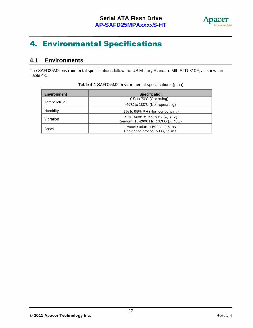
The SAFD25M2 environmental specifications follow the US Military Standard MIL-STD-810F, as shown in Table 4-1.
Table 4-1 SAFD25M2 environmental specifications (plan)
Environment Specification 0°C to 70°C (Operating)
Temperature -40°C to 100°C (Non-operating)
Humidity 5% to 95% RH (Non-condensing)
Vibration Sine wave: 5~55~5 Hz (X, Y, Z) Random: 10-2000 Hz, 16.3 G (X, Y, Z)
Shock Acceleration: 1,500 G, 0.5 ms Peak acceleration: 50 G, 11 ms

Serial ATA Flash Drive AP-SAFD25MPAxxxxS-HT
28 © 2011 Apacer Technology Inc. Rev. 1.4
5. Electrical Specification
Caution: Absolute Maximum Stress Ratings – (Applied conditions greater than those listed under “Absolute Maximum Stress Ratings” may cause permanent damage to the device. This is a stress rating only and functional operation of the device at these conditions or conditions greater than those defined in the operational sections of this data sheet is not implied. Exposure to absolute maximum stress rating conditions may affect device reliability.
Table 5-1 Operating voltage
Ambient Temperature 5V
0°C to 70°C 4.5-5.5V
Table 5-2 Absolute maximum power pin stress ratings
Parameter Symbol Conditions
Input Power VDD -0.3V min. to 6.5V max.
Voltage on any pin except VDD with respect to GND V -0.5V min. to VDD + 0.5V max.

Serial ATA Flash Drive AP-SAFD25MPAxxxxS-HT
29 © 2011 Apacer Technology Inc. Rev. 1.4
6. Physical Characteristics
6.1 Dimension
Unit: ㎜ Tolerance: � 0.2㎜
Power Segment Pin 1 Signal Segment Pin 1

Serial ATA Flash Drive AP-SAFD25MPAxxxxS-HT
30 © 2011 Apacer Technology Inc. Rev. 1.4
Unit: ㎜ Tolerance: � 0.2㎜

Serial ATA Flash Drive AP-SAFD25MPAxxxxS-HT
31 © 2011 Apacer Technology Inc. Rev. 1.4
7. Product Ordering Information
7.1 Product Code Designations
AP – SAFD 25 M P A x x x x S – H T
Capacity: 001G: 1GB 002G: 2GB 004G: 4GB 008G: 8 GB 016G: 16 GB
Environmental Spec
Version Control
Serial ATA Flash Drive
Apacer Product Code
2.5 inch Form Factor
Product Type
Apacer Brand
Solution Version
Flash Type

Serial ATA Flash Drive AP-SAFD25MPAxxxxS-HT
32 © 2011 Apacer Technology Inc. Rev. 1.4
7.2 Valid Combinations
Capacity Model Number
1GB AP-SAFD25MPA001GS-HT
2GB AP-SAFD25MPA002GS-HT
4GB AP-SAFD25MPA004GS-HT
8GB AP-SAFD25MPA008GS-HT
16GB AP-SAFD25MPA016GS-HT Note: Valid combinations are those products in mass production or will be in mass production. Consult your Apacer sales representative to confirm availability of valid combinations and to determine availability of new combinations.

Serial ATA Flash Drive AP-SAFD25MPAxxxxS-HT
33 © 2011 Apacer Technology Inc. Rev. 1.4
Revision History
Revision Date Description Remark
1.0 05/26/2009 Official release
1.1 06/18/2009 Supplemented quick erase related information
1.2 08/21/2009 Updated feature item
1.3 12/10/2009 Updated models & Changed coding rule
1.4 01/14/2011 Updated product ordering information

Serial ATA Flash Drive AP-SAFD25MPAxxxxS-HT
34 © 2011 Apacer Technology Inc. Rev. 1.4
Global Presence
Taiwan (Headquarters)
Apacer Technology Inc. 4th Fl., 75 Xintai 5th Rd., Sec.1 Hsichih, New Taipei City Taiwan 221 R.O.C. Tel: +886-2-2698-2888 Fax: +886-2-2698-2889 [email protected]
U.S.A.
Apacer Memory America, Inc. 386 Fairview Way, Suite102, Milpitas, CA 95035 Tel: 1-408-518-8699 Fax: 1-408-935-9611 [email protected]
Japan
Apacer Technology Corp. 5F, Matsura Bldg., Shiba, Minato-Ku Tokyo, 105-0014, Japan Tel: 81-3-5419-2668 Fax: 81-3-5419-0018 [email protected]
Europe
Apacer Technology B.V. Aziëlaan 22, 5232 BA 's-Hertogenbosch, The Netherlands Tel: 31-73-645-9620 Fax: 31-73-645-9629 [email protected]
China
Apacer Electronic (Shanghai) Co., Ltd 1301, No.251,Xiaomuqiao Road Shanghai 200032 China Tel: 86-21-5529-0222 Fax: 86-21-5206-6939 [email protected]
India
Apacer Technologies Pvt Ltd, #1064, 1st Floor, 7th ‘A’ Main, 3rd Block Koramangala, Bangalore – 560 034 Tel: +91 80 4152 9061/62/63 Fax: +91 80 4170 0215 [email protected]