sequential analog-digital computer analog-digital computer ... ferent arithmetic operations under...
TRANSCRIPT

SEQUENTIAL ANALOG-DIGITAL COMPUTER
Hermann Schmid General Electric Company
Light Military Electronics Department Johnson City, New York
INTRODUCTION
The applications of digital computers to analog control systems, where the inputs to the computer are the outputs from analog sensors and the outputs from the computer must drive analog controls, increase steadily, even in cases where analog computer accuracy (1 percent) would be sufficient. The reasons for this are:
• Digital computers, built with integrated circuits, are small, reliable, use little power and are insensitive to changes in environment.
• Conventional analog computers1,2 in comparison are large, unreliable, vary considerably with change in environment, require precision components, stable power supplies and many adjustments. In addition, conventional analog computers do not lend themselves easily to sequential operation.
Although the statements above are correct, a comparison of this type is worthless and often misleading because the interface equipment required with the digital computer is not included. In control
915
applications with ~any signals but few computations, the size, weight and cost of the interface circuits may equal, or even exceed, those of the computer. Besides, the analog-to-digital and digital-to-analog conversion circuits are subject to the same shortcomings and limitations as the analog computer circuits.
This paper describes a Sequential Analog-Digital Computer (SADC) which overcomes many of the limitations of the conventional techniques described above, by combining an analog arithmetic unit with a digital memory and a digital control unit. Tht; computer, thus, exploits the advantages of the analog technique (no interface circuits required, ease of summing and scaling, high resolution) with the advantages of the digital technique (drift-free storage, logic decisions, ease in signal switching). Except for a few precision components, SADC can be built entirely with integrated circuits.
There are only a few sequential analog computers described in literature3,4 and only one known technique which is similar to SADC.5 E. V. Bohn describes a pulsetime computer which uses vacuum tube integrators, vacuum tube current switches and a magnetic drum for storage.
From the collection of the Computer History Museum (www.computerhistory.org)

916 PROCEEDINGS - FALL JOINT COMPUTER CONFERENCE, 1965
COMPUTER ORGANIZATION
As shown in Fig. 1, the organization of SADC is very similar to that of a sequential digital computer. 6,7 SADC combines an analog arithmetic unit with a digital memory and a digital control unit in a unique way. The inputs to SADC may be a-c or d-c voltage or pulse-time signals, whereas the outputs are either in pulse-time or d-c voltage form.
ANALOG INPUTS
DIGITAL MEMORY
DIGITAL CONTROL UNIT (WITH ANALOG SWITCHES)
ANALOG L-___________ -A OUTPUTS
Figure 1. Basic building blocks of SADC.
Analog computing elements in the arithmetic unit are connected in various ways to perform different arithmetic operations under control of the program. The control unit connects signals to and from the arithmetic unit in appropriate time intervals according to the stored program.
The arithmetic unit performs each arithmetic operation without the use of the memory in one basic timing interval, no matter how complex. Often, the results of one arithmetic operation are used as the initial conditions for the next operation, thus eliminating the need for storage and associated transfers.
Pulse-time signals are used for transferring information from the arithmetic unit to the memory, and vice versa. The outputs of SADC are not provided continuously (sampled-data) , and one buffer element is required for each output signal, just as in a sequential digital computer.
ARITHMETIC UNIT
The arithmetic unit in Fig. 2 consists of integrators, inverters and comparators which may be used separately or combined. One integrator and one comparator perform; e. g., multiplication or division.
The design of the analog integrator is conventional,1,2 with resistor R in input and capacitor C in the feedback path of a high-gain operational amplifier, the output of which is
The quality of this integrator depends on the precision and the stability of R, C, and on the zero offsets of the amplifier.
The design of the analog summer-inverter is also conventional,1,2 with resistors R31 to R 3n in the input and R4 in the feedback path of a high-gain operational amplifier, the output of which is
Vo = -[~ + ~ + ... + ~J R4 RSl RS2 Rsn
The quality of the inverter depends on the precision of R 3, R4, and on the zero offsets of the amplifier.
The comparator uses a differential amplifier and logic circuits to indicate on two wires the result of the comparison V o-V c. When ( V 0-V c) is larger than +2mv, the amplifier output Vp is + VB, and when (Vo-Vc) is smaller than -2mv, V p is zero. The transition from + VB to zero requires 50 nanoseconds. V P, which indicates the polarity of (Vo-V c), is stored in a flip flop. NOR-gating provides the pulse-time outputs Pt1 if (Vo-Vc) > 0, and Pt1 if (Vo-Vc) < O.
The number of integrators, comparators and inverters used in an arithmetic unit is a function of the problem complexity and the required computation speed. The larger the number of computing elements, the more arithmetic operations can be performed in parallel.
All amplifiers, resistors and capacitors are susceptible to changes in environment. The arithmetic unit and the power supply regulators, therefore, are put into a small oven, operating at 70 ± 2°C to minimize computation errors due to changes in temperature.
MEMORY
In the sequential analog computer, relatively few variable signals need be stored because:
• Arithmetic unit does not require storage when executing an arithmetic operation.
From the collection of the Computer History Museum (www.computerhistory.org)

SEQUENTIAL ANALOG-DIGITAL COMPUTER 917
R ~ I INTEGRATOR I VOl
VII ~~.l<---~---------------;,r
I COMPARATOR 1
T. I C2
R I ~ INTEGRATOR 2 V02
V'2 ~ I D-0 ...... ------,-----------------~,.
COMPARATOR 2 I Pt2 ..
j
Figure 2. Typical arithmetic unit.
• Inputs are continuously available. • Arithmetic unit has itself limited storage
capability. • Often, outputs of one operation remain as
inputs for the next operation.
Therefore, the requirements on the memory elements for the SADC are entirely different from those of conventional digital computer memory elements. For a pulse-time memory element, it is important that the circuitry can be packaged into integrated-circuit packages and that it can be driven
from and read by integrated circuits. The method of storing pulse-time -signals with continuously operating counters8 fulfills these conditions.
In the pulse-time memory as shown in Fig. 3 the output square-waves from the most significant stage of the master and the slave counter, both driven by the same frequency fe, are gated to detect the phase shift between them. This phase shift, which is proportional to the difference in count between these two counters, produces the pulse-width output signal tx.
The value of tx varies when the number of pulses
From the collection of the Computer History Museum (www.computerhistory.org)

918 PROCEEDINGS - FALL JOINT COMPUTER CONFERENCE, 1965
Ie ~---.-------l lO-BIT MASTER COUNTER 1----.--------.;- TO RING COUNTERS
MASTER 1'---_---'
TIMING GENERATOR ---- ---
lO-BIT SLAVE COUNTER
INPUT
RESET TO ZERO
RESET -----1-----+--1 MEMORY ELEMENT -J-. -----------
I ,
~ OUTPUT~
-i Ix ~
CLOCK SYNC MASTER
-----------.. -- .v--------j
TO OTHER MEMORY ELEMENTS
Figure 3.
reaching the slave counter is different from the number of pulses reaching the master counter. When pulses are added to the clock pulses fe, tx increases; when pulses are subtracted, tx decreases. When no pulses are added or subtracted, tx stays constant.
The memory can be read out nondestructively. To read in new information, the slave counter must be reset when the master counter is zero.
Only unidirectional counters are necessary. These may be available shortly in a single integratedcircuit package. One master counter, with appropriate buffers at output, can supply many slave counters with the reference square-wave signal.
CONTROL UNIT
The control unit in Fig. 4, which consists of the timing generator, the program generator and the input/output switches, regulates the flow of information to and from the arithmetic unit and the memory by energizing voltage switches and digital logic circuits.
The timing generator shown produces, in sequence, 24 timing signals of equal length by gating the outputs of a 4-bit high-speed ring counter with outputs of a 6-bit low-speed ring counter in 24 buffer NOR circuits.
Variable program storage, as in general-purpose machines,6,7 provides flexibility but requires writeread memories (cores, drum, etc.) . Special-purpose machines, using fixed or wired program storage, require simple read-only memories (rope cores, diode matrices, etc.).
Memory element.
In the fixed-storage program generator of SADC, the program memory and the digital switching are comprised in one logic network which combines timing control signals with pulse-time input signals and generates n analog switch control lines and m pulsetime output signals. The logic circuitry of the program generator can be defined precisely for any particular application with a specific set of Boolean equations.
The switching of analog voltages is still a problem at present when size and cost must be considered, since low-impedance integrated metallic oxide semiconductor (MOS) switches9 are not yet available, integrated photo-electric switches10 are too expensive ( $100) , and transformer-coupled transistor switchesll are too bulky. The best compromise is the direct-coupled transistor switch in Fig. 4, capable of switching signals with ± 5V excursions but which require a base drive from - 6V to + 12V, a low source and high load impedance. The voltage across the saturated transistor VeE is dependent on the signal voltage, the base current and the load current. In the proposed circuit, VeE is maintained within ± 2mv. Special driver amplifiers, presently built with one transistor, are required to provide the largeswing base drive signal. Zener diodes are used to shift the level from zero to - 6V.
ARITHMETIC OPERATIONS
A change in the interconnection of the computing elements permits the execution of various arithmetic operations. The program specifies in each operation interval Ti what arithmetic operations are to
From the collection of the Computer History Museum (www.computerhistory.org)

SEQUENTIAL ANALOG-DIGITAL COMPUTER 919
F 9
~~>l-I ---------------------.------ ; ~f~ ANALOG INPUT SIGNALS
PROGRAM GENERATOR LOGIC
./'----'\,IV\r- + 12 V
TO ARITHMETIC UNIT
PULSE TIME SIGNALS FROM ARITHMETIC UNIT + MEMORY
(PROGRAM MEMORY + DIGITAL SWITCHING)
PULSE TIME SIGNALS TO MEMORY + ARITHMETIC UNIT
24 OPERATION TIMING SIGNALS
Figure 4. A control unit for 24 sequential operations.
be performed and how the various computing elements must be interconnected by energizing the appropriate analog and digital switches. The arithmetic unit in Fig. 2 can perform -two multiplications, two divisions, two additions, two SET or two READ operations simultaneously.
In all arithmetic operations, a voltage or voltagetime function is integrated for a controlled period of time. The integrator output voltage V o, at the end of the integration period, or the time required to make Vo equal to some specific potential, are the results desired.
The SET operation establishes the initial conditions prior to some arithmetic operations by integrating a certain analog voltage during Ti or by integrating a reference voltage V R during a certain pulse time.
The READ operation converts the output voltage Vo into a pulse time after certain arithmetic operations by integrating a reference voltage with appropriate sign until Vo is zero.
Often, however, the voltage outputs of one arithmetic operation are the inputs or the initial conditions for the next operation. Most SET and READ operations are thus eliminated.
Information is transferred from one computing element to another by having pulse-time signals, generated by a READ operation on the transmitting element, control a SET operation on the receiving element. When the TRANSFER operation is applied twice between two elements, errors due to variations in the time constants and the reference voltage cancel.
Each arithmetic or auxiliary operation is completed in one operation interval Ti • All intervals are of equal length and only one occurs at anyone time.
Conversion of Signals
The arithmetic unit may be used to convert analog signals from one form into another form. Any conversion can be performed before or in between the arithmetic operations of a computer program.
The conversion from pulse time to d-c voltage requires only a SET operation.
The conversion from d-c voltage to pulse time, which is usually referred to as pulse-width modulation,12 requires a SET operation to be followed by a READ operation.
From the collection of the Computer History Museum (www.computerhistory.org)

920 PROCEEDINGS - FALL JOINT COMPUTER CONFERENCE, 1965
The conversion from a-c voltage to d-c voltage is performed by integrating one-half cycle of an a-c signal. The integrator output voltage at the end of a half-cycle is proportional to the amplitude of the a-c voltage.
The conversion from a-c voltage to pulse time is performed similarly to a d-c to pulse-time conversion.
The conversion from three-wire synchro signals to pulse time13 is accomplished by converting into two-wire signals with a Scott T transformer and by performing a-c to d-c conversion on each of these two signals. At the end of the integration interval, the integrator voltages are:
VOl =.kEo sinA V02 = kEo cosA
and present the components of a vector R. A coordinate transformation operation is performed in
R
the next half-cycle by rotating R until V02 is zero. The time required for this rotation is proportional to the angle presented by the synchro signals, but independent of the reference voltage amplitude Eo and the synchro transformation ratio k.
Conversions with a-c voltage inputs require that the computer timing is synchronized to the a-c signal.
Addition -Subtraction
Any addition can be performed serially or parallel; subtraction is performed by negative addition.
Parallel addition, as shown in Fig. Sa, is carried out by summing currents,1,2 proportional to the variables in the sum, at the input of the integrator or the inverter. Since this requires additional precision resistors, parallel addition is used only when sequential addition is too time consumIng.
R
~:=+ 1: t G;l~ .. Vo
I I~ Vn~~ VO =Vl+V2 +---+Vn
IT. I
Figure 5a. Parallel addition with inverter or integrator.
Sequential addition, as shown in Fig. 5b, is carried out by integrating each of the voltages representing a variable for one operation interval, separately and sequentially in time, and without resetting the integrator. Sequential addition can be performed also with a memory element.
V1~
Integration
Integration, as illustrated in Fig. 6, is approximated by sequential addition in a modified memory element. The pulse-time memory element has a capability of summing and storing information and,
V2~~-----f I I ...__---'\.J'V'R ..r--<"""-'; D -C V 0
I I I ] T] T2 Tn V n _. -~--crf o-J fi· f f ~ I V 0 = RC V 1 dt + V 2dt + •••• + V n dtJ IT T1 T2 n -0 T1 Tn-1
:C [V]+V2+ •••• + Vn] Figure 5b. Sequential addition with integrator.
From the collection of the Computer History Museum (www.computerhistory.org)

SEQUENTIAL ANALOG-DIGITAL COMPUTER 921
thus, has a capability of approximating integration. Rectangular or trapezoidal integration7 is per
formed by summing properly scaled fractions or multiples of the integrand in the memory element once or several times during each computing interval.
To provide adequate input and output resolution, a 10-bit delta counter must be added to the memory element, to which Ie is connected when tx (representing an integrand X) is present. The delta counter fills up and overflows at a rate Rx which is propor-
f c
ADD/ U SUBT. I :
L ___ _
tional to tx• Each time the delta counter overflows a fixed number of pulses NT is added to the clock pulses for the slave counter. The time constant of the integrator is inversely proportional to NT.
The computing elements in the arithmetic unit perform the required scaling or mUltiplying and the conversion of the integrand into a pulse-time signal.
Integrations in the SADC are subjected to all limitations of numerical integration, but have no other intrinsic limitations.
20-BIT SLAVE COUN~ I
MEMORY ELEMENT
tc..---.olo--- lO-BITDELTACOUNTER r- R~x"'tx FROM MASTER COUNTER I
t x
Figure 6. Digital pulse-time integrator.
Multiplication One variable must be a d-c voltage, the other a
MUltiplication, as shown in Fig. 7, is performed by integrating a voltage V x for a time t y • The voltage across the integrator at the end of ty is proportional to the product XV, when V x is constant during ty ,
since
Vo = 1
RC
pulse-time signal. If both are d-c voltages, one must be converted into pulse-time form; if both are pulsetime signals, one must be converted into a d-c voltage.
The pulse-time signal ty operates the switch which connects the voltage Vx to the integrator. Both signals may be bipolar.
From the collection of the Computer History Museum (www.computerhistory.org)

922 PROCEEDINGS -- FALL JOINT COMPUTER CONFERENCE, 1965
PULSE WIDTH ... j::-=--=--=--t-y =--=-T--l-;---.... ·t------T -------:;· .... 1
INPUTt -I y ~ I ~ __ ~~
.A-------.- Vo ,.., X • Y
INTEGRATOR OUTPUT Vo
~TIME""'Y
Figure 7. Multiplication waveforms.
Division
Division, as illustrated in Fig. 8, is performed by integrating V u until the output of the integrator reduces from V w to zero.14
The voltage V u represents the divisor; V w represents the dividend which must be set into the integrator before the division operation starts. The integrator output voltage decreases with a constant slope as:
Vo(t) = Vw 1
RC
when Vo (t) is zero, tQ = V w/kVu
INTEGRATOR OUTPUT Vo
V u is connected to the integrator by an analog switch which is controlled by the pulse-time signal tQ, which starts at the beginning of the operation interval and ends when the integrator output voltage reaches zero. V w can be either a positive or a negative potential. V u must have the opposite polarity of Vw •
Arbitrary Function Generation
In SADC arbitrary functions are approximated with linear segments.15 A staircase waveform approximating f' (x), which is the derivative of the desired function, is generated by connecting the reference voltage sequentially to the set of scaled
TIME,.., W/V
;'~I5------T -----~ PULSE WIDTH ... ~.-___ tQ __ --il"'~1 OUTPUTt~ I
Figure 8. Division waveforms.
From the collection of the Computer History Museum (www.computerhistory.org)
SEQUENTIAL ANALOG-DIGITAL COMPUTER 923
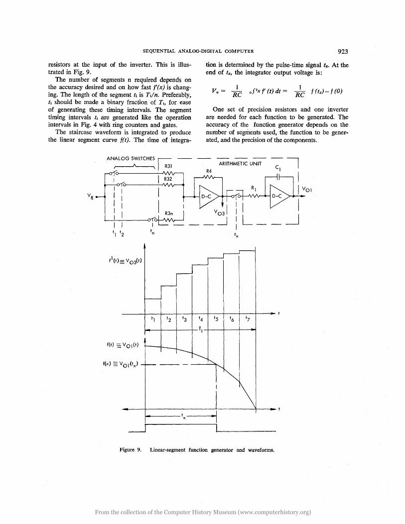
resistors at the input of the inverter. This is illustrated in Fig. 9.
tion is determined by the pulse-time signal t%. At the end of tx, the integrator output voltage is:
1 Vo= -
RC 1
RC f (tx) - f (0)
The number of segments n required depends on the accuracy desired and on how fast f (x) is changing. The length of the segment ti is Til n. Preferably, ti should be made a binary fraction of Ti , for ease of generating these timing intervals. The segment timing intervals ti are generated like the operation intervals in Fig. 4 with ring counters and gates.
The staircase waveform is integrated to produce the linear segment curve f( t). The time of integra-
One set of precision resistors and one inverter are needed for each function to be generated. The accuracy of the function generator depends on the number of segments used, the function to be generated, and the precision of the components.
ANALOG SWITCHES ~ -- -- -- -- --
~ ~R31 R4 ARITHMETIC UNIT Cl
I R32 ~ ___ ---J
I D-C
_! R3n I V 031 : I +----.!.---~I~ ___ ~ : L __
tn
f(x) == VOl (tx)
t4
~_+---+---~Ti~---+---+--~
Figure 9. Linear-segment function generator and waveforms.
I I
From the collection of the Computer History Museum (www.computerhistory.org)

924 PROCEEDINGS - FALL JOINT COMPUTER CONFERENCE, 1965
The generation of inverse function can be accomplished by setting the integrator to VI: and then integrating a voltage function g' (t) until VOl is zero. The time required to reduce VOl from V x to zero is the desired inverse function, since:
(x Vx - 0) g'(t)dt = Vx - g(tx) + g(o)
or, if g(o) = 0
VOl = C I COS w t
.5
.866
-.5 (9
Coordinate Rotations/Transformations and Trigonometric Function Generation
The electronic analog resolver13 rotates and transforms coordinates and generates trigonometric equations by controlling the initial conditions and the operating time of an harmonic oscillator (Fig. 10).
Two integrators and one inverter are connected into a loop as an harmonic oscillator to solve the differential equations X = -kX. The outputs of the integrators, Volt) and V02(t) , are the solutions to the differential equations and represent the components
V02 = C SIN w t
-.5
~ 1-
V02
.866
R4
+1.0
®
VECTOR IS ROTATED FROM -300 TO +600 ANGLE VECTOR IS FOUND TO BE 1350
Figure 10. The controlled harmonic oscillator and wave·forms.
From the collection of the Computer History Museum (www.computerhistory.org)

SEQUENTIAL ANALOG-DIGITAL COMPUTER 925
of the imaginary vector R. The vector R "rotates" with constant velocity when
the harmonic oscillator loop is closed and the integrator outputs change in a sinusoidal fashion. The time during which the loop is closed is directly proportional to the angle through which R is rotated, since A = kwt.
Coordinate rotation can be performed by rotating R from its initial components V x, V y for a time tA, which is proportional to the desired angle of rotation. The integrator voltages at the end of tA represent desired outputs, since
Tl T2 T3
0 0 DD
-DE
DN
AJ1..
Coordinate transformation can be performed by rotating R from its initial components V x, V y until Vodt) becomes zero. The time required for Vodt) to decrease from V y to zero is:
The value of V 02 at the time t = tA' is:
The initial components V x, V y are SET into the integrator prior to the rotation or transformation operation.
Modification of the basic rotation and the transformation equations permits the generation of sine,
Ta T9
0 0 DX .. Dy
---Dz -
9 -1"1- ,.0.rL
Figure 11 a. Flow diagram with arithmetic unit in figure 2.
FLOW DIAGRAM LEGEND:
o o
= INTEGRATOR & COMPARATOR
= MEMORY ELEMENT
--DX
_Dy
_Dy
Figure lIb. Flow diagram with arithmetic unit having three integrator-comparator combinations.
From the collection of the Computer History Museum (www.computerhistory.org)

926 PROCEEDINGS - FALL JOINT COMPUTER CONFERENCE, 1965
cosine, arcsine, arccosine, and other trigonometric functions. Similarly, the solutions to the differential equations X = + kX and X = -kX can be exploited to generate exponential, logarithmic and hyperbolic equations.
APPLICATION
The application of the SADC to the coordinate conversion problem demonstrates the elegance of this method of computation and emphasizes most of the advantages.
Conversion from earth coordinates to ship coordinates, as frequently used in navigation, ground control of missiles, fire control, etc., is defined by the matrix equation:
[DX] [1 0 0] [coso 0 -Sin(/)] Dy = 0 cosfj} sin(/) 0 1 0 Dz O-sinfj} cos(/) sinO 0 cosO
which can also be written as:
Dx = (DN cosA + DE sinA) cosO - DD sinO
Dy = (DE cosA - DN sinA) cos(/) + [(DN cosA + DE sinA) sinO + DD cosO] sin(/)
Dz = (DN sinA - DE cosA) sin(/) + [(DN cosA + DE sinA) sinO + DD cosO] cos0
where Dx, Dy, Dz are ship coordinates; DN, DE, DD are earth coordinates; and A, 0, (/) are azimuth, pitch and roll angle, respectively.
The programming of the SADC is best illustrated with the flow diagrams in Fig. 11, in which each column of squares represents the arithmetic unit and the required memory elements in one operation interval. Inputs to and outputs from a computing element and its function are explicitly indicated: S = SET initial condition, 0 = READ OUT, R = ROTATION, H = HOLD. A resolver operation is depicted by interconnecting two squares.
With the coordinate inputs DN, DE and DD in a-c or d-c voltage form and the angles A, 0 and (/) in pulse-time form, the coordinate conversion problem can be solved in two ways.
Solution 1: With the arithmetic unit in Fig. 1 and one memory element, the problem can be solved in nine operation intervals Ti.
Solution 2: With an arithmetic unit consisting of three integrator-comparator combinations, the problem can be solved in five operation intervals Ti, and without the use of any memory element.
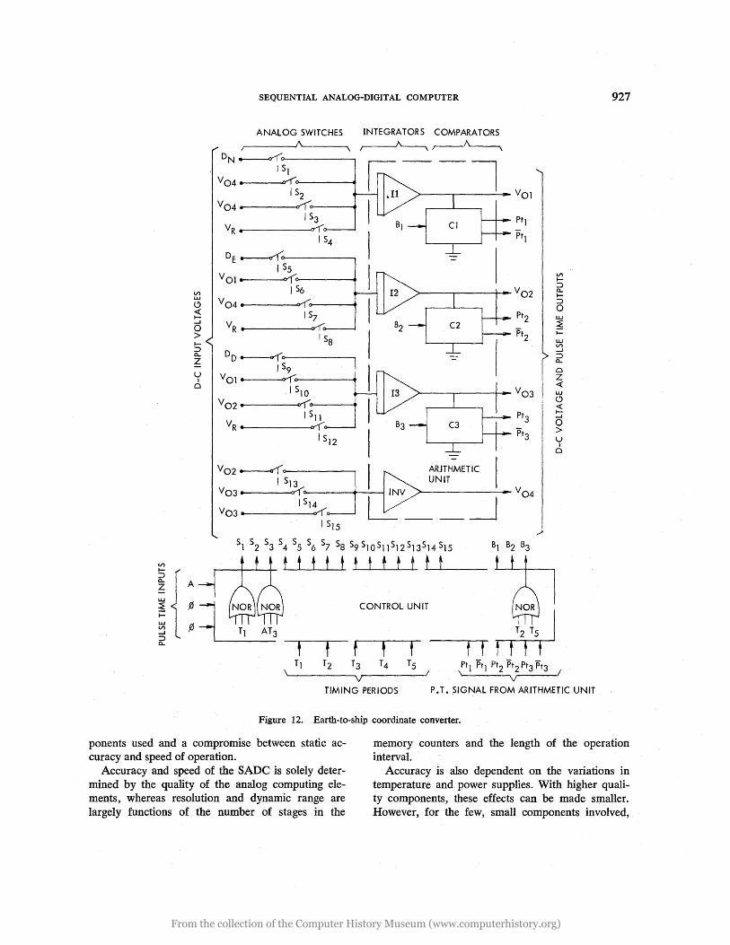
Coordinate Converter Circuit
A SADC solving the coordinate conversion problem according to Solution 2 consists, as shown in Fig. 12, of the arithmetic unit with three integrator-comparator combinations, the 15 analog voltage switches, the timing generator, and the controllogic.
It is assumed that the coordinate inputs DN, DE and DD are d-c voltages and the angle inputs are in pulse-time form. The output signals D x, Dy and Dz appear in pulse-time form.
The required number of analog voltage switches and digital logic circuits can be derived most easily from a list of input signals which must be connected to the integrators and inverter in the arithmetic unit during each of the five time periods Ti •
Timing Integrator Integrator Integrator Inverter Periods I II III
Tl DN DE DD Tz V04 VOl V 02
T3 V04 VOl V03
T4 V04 V02 V03
T5 VR VR VR
The circuit in Fig. 12 can be built with approximately 25 digital integrated circuits (flip-flops and NORs) and 25 linear integrated circuits (amplifiers and analog voltage switches). It would require less than ten watts of power, less than 100 cubic inches in volume, and weigh less than five pounds.
To perform the same problem with a conventional analog or a conventional digital computer would require a circuit complexity at least one order higher.
PERFORMANCE
The performance of any analog computing element is always a function of the quality of the com-
From the collection of the Computer History Museum (www.computerhistory.org)
V) w o <{ I.....I
o > I:::> 0-
Z
U I
£:)
SEQUENTIAL ANALOG-DIGITAL COMPUTER
ANALOG 5WITCHE5 INTEGRATORS COMPARATORS /,-----.1(\'-----____ ~ ~
DN ~:>-------...... I Sl
V04~.-----~:>---------~ I S2
V04~.------~~~----~ 153
VR .... ------"..-r, I S4
DE~~------~ I S5
VOl. ~:>---------~ 1 56
V04 • ~~---~ 157
VR • ~ I Sa
DD~~------~ I S9
VOl. ¥(cr------~ I S10
V02 • ~r----~ I Sl1
YR· ~ I S12
V02~~13 ~ V03. ~o
I S14 V03. ~
I 515
Sl 52 S3 S4 S5 S6 S7 Sa 59S10S11S12S13S14S15
~~~t t t t t t t t t t~t~t __ _
CONTROL UNIT
t t t ,
I ,.)
Tl T2 T3 T4 T5 Pt1 Ptl Pt2 Pt2 Pt3 Pt3 \ \
V v
V) f:::> 0-I:::> o w ~ f-
w V) ....J :::> 0-
Q
Z <{ w o <{ I....J
o > U
I £:)
/
TIMING PERIODS P. T. ~IGNAL FROM ARITHMETIC UNIT
Figure 12. Earth-to-ship coordinate converter.
927
ponents used and a compromise between static accuracy and speed of operation.
memory counters and the length of the operation interval.
Accuracy and speed of the SADC is solely determined by the quality of the analog computing elements, whereas resolution and dynamic range are largely functions of the number of stages in the
Accuracy is also dependent on the variations in temperature and power supplies. With higher quality components, these effects can be made smaller. However, for the few, small components involved,
From the collection of the Computer History Museum (www.computerhistory.org)

928 PROCEEDINGS - FALL JOINT COMPUTER CONFERENCE, 1965
it is cheaper to control the environment of the arithmetic unit.
The performance data given below refer to an arithmetic unit with the following components, timing and environment:
Amplifiers:
Analog Switches: Resistors: Capacitors:
Fairchild /LA 702 adjusted for zero offset Direct-coupled 2N2432 ±0.05% of nominal value Trimmed to ±0.05% of nominal value
Temperature: 25°C ± 2°C Operation Interval: 1 ms Power Supplies: -6V ± 0.1 %, +5V ±
10%, +12V ± 1% Static accuracy for addition, multiplication, divi
sion, * integration, SET, READ and transfer operations is ±0.1 % of full-scale and ±0.2% for coordinate rotation, coordinate transformation, * sine-cosine generation, etc.
With a I-ms operation interval, 1,000 sequential operations can be performed in 1 second.
CONCLUSION
The ability of computing analog and storing digital provides the SADC with the unique capability of operating as a sequential computer which accepts analog signals as inputs and provides analog signals as outputs, and operates with analog computer accuracy and sequential digital computer speed.
Time-sharing the simple arithmetic unit and requiring no interface circuits make the SADC the most economical method of computation in its speed-accuracy domain.
Due to the small number of components used and due to the fact that almost all of these components are integrated circuits, SADC has an inherently high reliability. In addition, redundancy techniques can be applied to SADC just as to a digital computer.
The performance figures given have been obtained with relatively low-performance integrated analog circuits. With better components, such as chopper-stabilized amplifiers, higher precision will be possible. However, in achieving and maintaining this ~igher accuracy, there may be a problem in finding accurate and stable capacitors.
To date, only parts of the SADC have been built
*Only when inputs are larger than 50 percent of full-scale.
and tested, and considerably more work is neededboth at the circuit and system levels.
With its inherently high reliability, minute size, low power consumption and minimum cost, the SADC should be well suited· for all those military and industrial control applications where the computer inputs and outputs must be in analog form.
REFERENCES
1. G. A. Korn, Electronic Analog Computers, McGraw Hill, New York, 1956.
2. S. Fifer, Analog Computation, Volumes 1 to 4, McGraw Hill, 1961.
3. R. Lee and F. Cox, "A High-Speed Analog-Digital Computer for Simulation," IRE Transactions on Electronic Computers, June 1959, pp. 186-196.
4. A. Herzog, "Pulsed Analog Computer for Simulation of Aircraft," Proc. IRE, May 1959, pp. 847-851.
5. E. V. Bohn, "A Pulse Position Modulation Analog Computer," IRE Transactions on Electronic Computers, June 1960, pp. 256-261.
6. M. Phister, Logical Design of Digital Computers, John Wiley and Sons, 1959.
7. R. S. Ledley, Digital Computer and Control Engineering, McGraw Hill, 1960.
8. W. R. Seegmiller and E. C. Underkoffler, "Static Sync Drive Development," General Electric Company TIS Report R61APS47 (Dec. 1961).
9. H. Ruegg, "An Integrated FET Analog Switch," Solid-State Conference, Philadelphia, Pa. (Feb. 1964).
10. No author, "Molecular Opto-Electronic Multiplex/Chopper," Texas Instruments, Product News Release (March 23, 1964).
11. H. Schmid, "Four-Quadrant All-Electronic Pulse-Time Multiplier," General Electric Company TIS Report 62APJ 43, pp.II-13.
12. H. Schmid, and B. Grindle, "Inexpensive Pulse-Width Modulation," Electronics, pp. 29-31, Oct. 11, 1963.
13. H. Schmid, "Electronic Analog Resolver," to be published in Electronics.
14. H. Schmid, "Repetitive Analog Computing Technique," Aerospace Conference, Phoenix, Arizona, April 1964.
15. H. Schmid, "Linear Segment Function Generator," IRE Transactions on Electronic Computers, Dec. 1962, pp. 780-788.
From the collection of the Computer History Museum (www.computerhistory.org)