september 2008, brasil state of art of rcd dams in japan · state of art of rcd dams in japan...
TRANSCRIPT

State of art of RCD dams in Japan
Estado da Arte do RCD barragens no Japão
Shigeyoshi NAGATAKI
September 2008,Brasil

Contents1. Introduction2. History of RCD dams in Japan3. Planning of RCD construction method 4. RCD Concrete5. Tranportaion system of RCD concrete6. Concrete works in RCD construction
method7. New approaches in RCD construction
method

1. IntroductionRCD (Roller Compacted Dam concrete) construction method is a rationalized construction method for concrete dams which was developed by the Ministry of Construction, Japan in 1970’s, as the first roller-compacted concrete construction method prior to RCC (Roller Compacted Concrete). Through many RCD dam’s experiences, RCD construction method has achieved reduction of the construction period, the labor cost, the environmental issue, and the hazard in safety for the constructor.
1.1 Features of RCD concrete and RCD construction method1.2 Philosophy and background of RCD construction method1.3 Comparison between RCD and RCC
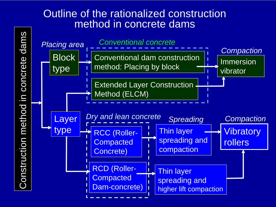
Outline of the rationalized construction method in concrete dams
Extended Layer Construction Method (ELCM)
Conventional dam construction method: Placing by block
Conventional concrete
Immersion vibrator
Layer type
Block type
Placing area
Vibratory rollers
RCD (Roller- Compacted Dam-concrete)
RCC (Roller- Compacted Concrete)
Dry and lean concrete Compaction
Compaction
Con
stru
ctio
n m
etho
d in
con
cret
e da
ms
Thin layer spreading and compaction
Thin layer spreading and higher lift compaction
Spreading
1.1 Features of RCD concrete and RCD
construction method
a. RCD concrete is extremely dry and lean concrete in order to improve transportability and reduce hydrated heat. The Ministry of Construction made up RCD concrete under a new mixture concept to keep the same quality in strength and density as the conventional concrete has.
b. Further, Japan established RCD construction method to manage this RCD concrete. In this method, the concrete is spread in several thin layers over the entire dam surface and is compacted by vibratory rollers

Procedures of RCD concrete works
①Unloading dump trucks
②Spreading by bulldozers
③Transverse joints by cutters
④Compaction by vibratory rollers
⑥Green cut and cleaning
⑤Curing24~48hr
⑦mortar SpreadingConcrete plantConcrete work cycle of RCD construction method
Unloading concreteSpreading by bulldozer
Bulldozer
1. Dry and lean concrete is transported from the concrete plant to the placing site by dump trucks or other means and the concrete is unloaded.
2.The concrete is spread out using bulldozers by thin layers.
3.Transverse joints are made using vibratory joint cutters in the above time.
Compaction by vibrating roller
Downstream
Vibratory blade
machine
4.The concrete is compacted using vibratory rollers after all concrete spread.
5.The concrete is then cured for 24 ~48 hours in wet and stable environment.
6.Lift surfaces of the concrete should be treated by green cut.
7.The mortar is spread out before the next concrete is unloaded in the placing area.
Vibratory rollerWet curinggreen cut machine Spreading mortar
External concrete
Internal zone of RCD concrete
Downstream Concrete hopper

1.2 Philosophy of RCD construction method
For example; a. Transverse contraction joints are installed every 15 m in
order to prevent temperature cracks in the dams.b. Conventional concrete with high quality is placed at the
upstream and the downstream surfaces of the dams in order to obtain water-tightness and high durability.
c. Lift joints (horizontal surfaces) are treated in the same way as the conventional concrete dams in order to assure good bond and water-tightness between the lifts.
The philosophy of RCD is to keep the same performance as conventional concrete dams and to satisfy the same design criteria as conventional concrete dams , while to pursue the improvement of economy, safety, and environment.Therefore, RCD is a construction method to rationalize the dam construction works and the required functions of RCD dams are the same as that of conventional concrete dams.

1.3 Comparison between RCD and RCC
Miyagase dam
Kinta dam, Malaysia
RCD is compacted by a higher lift than RCC. RCD is possible to place more concrete than ELCM. However, They have many common concept and technical know-how.
Sunakozawa dam, 7.2006
DownstreamELCMRCC
RCD

Comparison between RCD and the other types of concrete
(internal zone) Conventional dam concrete, ELCM* RCD concrete High paste
RCC concreteRCC
in Kinta dam Property of concrete
dry and lean concrete
extremely dry and lean
High paste concrete
High paste concrete
Unit content kg/m3
W: water, C: cementW=105~115
C+F=130~160W=80~105
C+F=110~130W=100~150
C+F=150~300W=150
C+F=200F/C+F, F: fly ash 20~40% 20~40% ≧50% 50%
Max size of aggregate 80~150mm 80~150mm Mostly
40~65mm 63mm
s/a :sand/aggregate 25~30% 28~34% Higher than RCD 41%
Consistency test Slump value: 2~4cm
VC value: 10~25sec
VB value: 10~17sec
VB value: 12~17sec
Thickness of a lift 1.0m/1.5m 0.75m/1.0m 0.3m~0.4m 0.3m (slope layer)
Transverse Joint Block formed by 15m span
Cut by 15m span using joint cutter
Cut by 15~60m span using joint cutter
Cut by 20m span using joint cutter
Lift Joint treatment Green cut +cleaning + mortar spreading
Green cut + cleaning+ mortar spreading
Nothing to do until setting start
Nothing to do in 5hr after placing

The relationship between RCC and RCD concretes from the view of paste contents and density or strength of concrete.
RCC concrete
High paste RCC
Midium paste RCC
→ High paste
Den
sity
or s
treng
th o
f co
ncre
te
Low paste RCC
CSG
Content of cement and fly ash
RCD concrete
CSG: Cemented Sand and Gravel, new material for dams
High
Conceptual position of RCC & RCD concrete

2. History of RCD dams in JapanThe first applied RCD dams was Shimajigawa dam and Ohkawa dam. The both dams were completed in l980. Then, RCD construction method was applied to Tamagawa Dam. In the latter half of 1980's, RCD construction method was also adopted at many dams. In 1990's, RCD construction method raised technical completeness by the large-scale dam execution such as Ryumon dam, Miyagase dam, Urayama dam, and Gassan dam. At the same time, RCD construction method was adopted in many middle-scale dams. After 2000, Takizawa dam and Nagai dam achieved some improvements. Today in Japan, Kasegawa dam and other several dams are challenging to progress to a new stage of dam technology for the sustainable future.
Shimajigawa dam Miyagase dam Origawa dam

Shimajigawa
Ohkawa
Tamagawa
Ryumon
Map of RCD dams by the transportation method
Damp trackIncline Tower craneCable craneBelt-conveyorUnder construction
RCD dams grouped by the transportation method
5.Chubu
3.Kanto
2.Tohoku
1.Hokkaido
4.Hokuriku
9.Kyushu
7.Chugoku
8.Shikoku
6.Kinki
10.Okinawa
Miyagase
Urayama
Gassan
Tomisato
Origawa
Chubetsu
Nagai

3. Planning of RCD construction method
The basic plan of RCD construction method is decided by considering the schedule, temperature control, compacting thickness, construction facility capacity, geography, geology, climate and environment.
3.1 Zoning of dam concrete 3.2 Lift schedule 3.3 Temperature control3.4 Choice of concrete plant capacity and mixer type3.5 Choice of transportation system3.6 Simplification of inside structures of dam body

3.1 Zoning of dam concrete
The upstream and downstream of dam surfaces should be covered by high quality concrete to maintain water- tightness and durability to protect the concrete from freeze-and-thaw attack or other aging.RCD concrete is placed in internal zone
1~3m
Cross section of RCD dams classified by concrete mixture
B1:internal concrete zone:RCD concrete
A2: Downstream external concrete zone
8~15mA1:
Upstream external concrete
zone
A3: structural concrete zone
A3: foundation concrete zone
B2: internal concrete zone
2.5~3m
2~3m

3.2 Lift scheduleIn RCD construction method, much more concrete can be placed. Therefore it is extremely important to plan an appropriate lift schedule to obtain construction efficiency and to prevent temperature cracks.
By YearBy Month
RCD concrete transported by 20ton Dump truck
20ton Dump truck ELCM20ton Dump truck RCD13.5ton Cable crane
150ton Crawler crane
150+80ton Crawler crane
80ton Crawler crane 150ton Crawler crane+ Dump truck

Lift thickness 1m
In order to speed up construction and to reduce the number of lift surface treatments, lift thickness had to be increased. Thick lift placement prevents the formation of a possible weak plane on the lift surface. At Tamagawa Dam, 1 m of lift thickness was made possible by thin layer placement. The thin layer spreading method used in RCD construction method completely differs from compaction in RCC construction which adopted compacting concrete in a single layer.
Compaction by vibratory rollers
spreading by bulldozer
06.2008, Kasegawa dam
4 layers: 1mExternal zone
Internal zoneRCD concrete
1 m of lift thickness was divided into four thin layers that were spread by bulldozers.

3.3 Temperature control
Temperature control plan should be prepared to prevent temperature cracks.1. To suppress the heat of hydration: Moderate-heat Portland
cement with fly ash is used and the unit cement content is reduced in RCD concrete.
2. Cutting of transverse joints: Experiences have shown that temperature cracks can be prevented mostly when the transverse joints are placed about 15 meters apart.
3. Curing RCD concrete: Through the term of concrete placing in most of RCD dams, the concrete is cured by ponding and water sprinkler. Further, in cold winter, the surfaces of concrete dams should be covered by heat insulators like as urethane materials.
4. Pre-cooling of materials: In the summer season, most of RCD dams have executed pre-cooling of concrete materials (mainly, water and coarse aggregates).
5. Another important step is to start the concrete placing from the more advantageous month. Miyagase dam started the concrete placing from September from this idea.

3.4 Choice of concrete plant capacityAs RCD construction method enables to place much more concrete, RCD concrete plants should have enough capacity to speed up the concrete placement. Figure shows that concrete plant capacities in RCD dams tend to be bigger and more in accordance with the dam volumes than the others, because RCD dams are more free from the restrictions of temperature control, concrete transportation and concrete placing.
0
50
100
150
200
250
300
350
400
0 500 1000 1500 2000Volume of dam body (1000 m3)
Concrete plant capacity (m
3 /h)
Convetional damsRCD damsELCM dams
Concrete plants to dam volumes

3.6 Simplification of inside structures
of dam bodyInside structures such as inspection galleries, temporary diversion channels, conduits and gates might affect the smooth concrete placing of RCD construction method. So, various simplifications of inside structures have been implemented to speed up the RCD concrete works in Japan. For example, they are adoption of precast members, rearrangement or shortcut of galleries to avoid duplication with concrete works, reposition or bridging of temporary diversion channels, course and elevation change of conduits, and improvement of complicated structural works which is a bottleneck of the rationalization.
Precast gallery
Conventional formwork
Kido dam in 7.2003
Photo shows the precast setting for inspection galleries to simplify formworks.

4. RCD Concrete
The requirements of RCD concrete mixes are the same as those of conventional concrete. The mixture design of RCD has been improved throughout the history of RCD construction method.
4.1 Requirement to RCD concrete 4.2 Material properties used in RCD concrete 4.3 VC (Vibrating Consistency) test 4.4 Mixture design of RCD concrete 4.5 Ratio of volume to void in concrete and mortar

4.1 Requirement to RCD concreteThe unit cement content and unit water content in RCD concrete are much less than those in the conventional concrete for dams.It is because RCD concrete should be extremely dry and lean concrete. Extremely dry concrete is required to allow the construction equipment to travel on fresh concrete. Lean concrete is required to minimize temperature rises which may cause temperature cracks.Hardened RCD concrete should have the same properties as conventional concrete, which is required to construct the safe and watertight concrete dams. Like conventional concrete, RCD concrete must have strength, unit weight, water tightness and durability to satisfy the requested performance.3

4.2 Material properties used in RCD concrete
Prior to mix design, materials should be selected like as below.1. Cement: moderate-heat Portland cement, and low hydration
heat type cements. The unit cementitious material (cement and fly ash) content was reduced to 110kg/m3.
2. Aggregates: Aggregates used in RCD concrete must have the same quality as those of conventional concrete. The maximum size of aggregate in RCD concrete is mostly 80 mm and sometimes l50 mm.
3. Finer particles: Reducing the cement paste content or mortar content may cause the segregation of the aggregates. It is improved by adding finer particles (50 % grain size of about 50 μm) to the fine aggregate.
4. Admixture: Fly ash is generally used as mineral admixture and 20 % to 40 % of cement is replaced by fly ash. The use of fly ash contributes to lowering the heat of hydration, improving consistency, and increasing long term strength.

4.3 VC (Vibrating Consistency) test
Since RCD concrete is dry and lean, the slump test cannot be used to measure its consistency. So, the VC test method was developed to measure the consistency of RCD concrete.There are two kinds of container used in the VC test: the standard-size (diameter 24cm) and the large-size (diameter 48cm) container. In the VC test using a standard- size shown in Photo 1, concrete wet screened up to 40mm or less is used. In the VC test using a large-size container shown in Photo 2, a full-size mix of concrete is applied.
Photo 2 :VC test with a large-
size container
Photo 1 :VC test with a standard size
container
Weight 20kg
RCD concrete
Container D24cm x h20cm
Weight 648kg
Vibrating table 3000cpm
Vibrating machine 1900cpm
Container D48cm x h40cm

4.4 Mixture design of RCD concrete
The success of RCD construction depends on the mixture design of RCD. In the development of RCD concrete, some new concepts are adopted. The mix design of RCD concrete is carried out as shown below.
The unit cement content must be kept lowest in order to prevent a high temperature rise, as long as the required workability, strength, and other properties are satisfied. Mostly, the unit cement content of RCD concrete is 110 to 130 kg/m3.
1) Unit cement content

2) Unit water content
The unit water content is determined so that adequate compacting can be achieved. In the VC test, the optimum water content is determined when the prescribed VC value is obtained. Normally, the optimum VC value is 20 seconds and the unit water content is 80 to 105 kg/m3.
large mold(φ48×h40 cm)
small mold(φ24×h30 cm)
125
150
100
75
50
25
080 90 100 110 120
Water Content (kg/m3)
VC
valu
e(
sec)
C + F = 120 kg/m3
Relation between Water Content
& VC value

3) Sand aggregate ratio
The optimum sand aggregate ratio is the ratio where the VC value is at its smallest. The sand aggregate ratio of RCD concrete is about 30% in general. In comparison to conventional concrete, the sand aggregate ratio in RCD concrete is higher. Full size mix of concrete is used in the VC test with a large-size container. In this VC test, the unit cement content and unit water content are held constant, but the sand aggregate ratio is varied.
200
150
100
50
0 26 28 30 32 34 36 4038
C + F = 130kg/m 3
W = 98kg/m 3
VCVA
LUE
(se
c)
SS+G
(%)sa=

Mortar
β=
coarse aggregate
Paste
α=
sand aggregate
Mortar
Mortar
Mortar
Paste
β in Concrete
4.5 Ratio of volume to void in concrete
and mortarTo find the optimum mixture ratio, the concepts of the coefficients α and β
are introduced. The ratio of paste volume to the voids in the sand aggregate is defined as α and the ratio of mortar volume to the voids in the coarse aggregate is defined as β. In order to fill the voids in coarse aggregate and sand with mortar or cement paste sufficiently, both α and β should be more than 1.
α in MortarPaste

According to this α and β concept, compared with α = 1.5 to 1.8, β = 1.2 to 1.5 of conventional dam concrete, and α = 2.1 to 2.4, β = 2.0 to 2.3 of structural concrete, α = 1.1 to 1.3, β = 1.2 to 1.5 are suitable values for RCD. It is noted in particular that the volume of cement slurry is close to the volume of voids between fine aggregates. This result shows that unit cementitious material content is in the range of C+F=110 to 130 kg/m3 and unit water content is in the range of W=80 to 105 kg/m3 for RCD.
Paste volumeVoids in the sand aggregateα=
Mortar volumeVoids in the coarse aggregateβ=
α and β values in RCD concrete

5. Transportation system of RCD con
Spectacular achievements in RCD construction method has been the improvement and diversification of transportation system. Because the construction surface of a dam built by RCD construction method is flat, dump trucks can transport RCD concrete to every pouring area on the dam. It provides greater freedom of choice of the transportation system from concrete batching and mixing plant to the dam. Accordingly, by selecting the most suitable transportation systems, there is less damage to the natural environment.
5.1 Dump truck (direct transportation system) 5.2 Incline 5.3 Cableway and tower crane5.4 Belt-conveyor

History of RCD concrete transportation system in Japan yearsystem
799 8210 844 8810 915 965 979 0211
878 9111 929 9611 056
789 809 857 8911 928 955Ohkawa dam basement
865 896 906 9312 956 9811 004 0310
934 969 9710 0012
904 937 939 9612 9911 037
8711 8912 949 9611
919 9311 003 0112dam
909 9212 0710
929
94.5 99.9
928 966
919 9311
839 876 885 911281.10 82.4Tamagawa coffer dam 85.4 87.12 91.4 94.11
87.10 91.1 91.10 95.1
87.9 92.6
78.8 80.8 92.6 95.12 01.7 04.9
969 0110
954 9712 0210 068
915 965 0210 078
90.3 92.8 95.8 97.11
year
History of RCD concrete tranportation system1978 1979 1980 1981 1982 1983 1984 1985 1986 1987 1988 1989 1990 1991 1992 1993 1994 1995 1996 1997 1998 1999 2000 2001 2002 2003 2004 2005 2006 2007 2008
Dumptruck
Shin- nakano basement Pirica dam Satsunaigawa dam Chubetsu dam
Asari dam Ohmatsugawa dam Toppu dam
Shiromizugawa dam Hinata dam
Asahiogawa dam Miyatoko dam Hayatine dam Koyama dam
Shiokawa dam Kubusugawa dam
Hattabara dam Shimagawa dam Kutani dam
Nunome dam Hiyoshi dam
Tsugawa dam Fukuchiyama
Ryumon dam Kasegawa
Beltconveyor
Takisato dam
Gassan dam
Urayama dam
Tsugawa dam
Incline
Tamagawa dam Kamuro dam
Mano dam Kodama dam
Dodaira dam Miyagase dam
Sakaigawa dam
Cablecrane
Chiya dam Takizawa dam
Origawa dam
Tomisato dam Kido dam
Towercrane
Satsunaigawa dam Nagai dam
Sabigawa dam Kazunogawa dam
1978 1979 1980 1981 1982 1983 1984 1985 1986 1987 1988 1989 1990 1991 1992 1993 1999 2000 20011994 1995 1996 1997 2006 2007 2008
Shimajigawa da
Obara dam
2002 2003 2004 20051998

5.1 Dump truck (direct transportation system)
The direct transportation from the mixing plant to the lift surface by dump trucks is most advantageous when the topographical conditions are suitable, because there are no other special transportation facilities and no reloading during transportation. The use of the direct transportation by dump trucks is also often applied to the lower part of the dams.
Dump truck, Toppu dam, 7.2005
Tranportation road
Downstream
Dump truck, Kutani dam, 2002
Liftup bridge
Downstream

5.2 Incline systemInclines can be adopted at the steep slopes and transport large amounts of concrete per hour. So, inclines have been often used at relatively large scale RCD dams without depending on the dam site topography. Dams constructed by the incline transportation system include Tamagawa dam, Miyagase dam and other dams.
Tamagawa dam, 1984
InclineDown stream
Miyagase dam, 1992
Concrete plant
Incline
Downstream
Counter weight
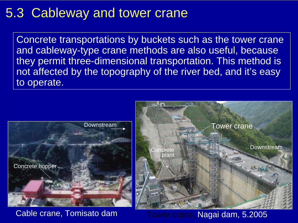
5.3 Cableway and tower crane
Concrete transportations by buckets such as the tower crane and cableway-type crane methods are also useful, because they permit three-dimensional transportation. This method is not affected by the topography of the river bed, and it’s easy to operate.
Tower crane
Tower crane, Nagai dam, 5.2005
Concrete plant
Downstream
Cable crane, Tomisato dam
Downstream
Concrete hopper

5.4 Belt- conveyor
Belt conveyers in Urayama dam
Belt conveyers are another important transporting system performed in high dams.Concrete transported from the concrete batching and mixing plant by belt conveyers was temporarily stocked in a ground hopper installed on the dam, then was transported by dump trucks to the placing area.
Belt conveyor, Gassan dam, 1995
Belt conveyor
Consolidation grouting
Concrete plant
Concrete hopperDownstream
Belt conveyor

6. Concrete works in RCD construction
method The concrete works in RCD construction method has been improved through many RCD dam experiences in Japan, because the compaction of RCD dry lean concrete by vibratory rollers need much more experiences and technologies.
6.1 Test filling of RCD concrete works 6.2 Lift joint treatment by green cut and mortar spreading 6.3 Unloading of concrete by dump trucks 6.4 Spreading of RCD concrete 6.5 Roller compaction of RCD concrete 6.6 Contraction joint (transverse joints)6.7 Compaction between different concretes 6.8 Curing 6.9 Quality control

6.1 Test filling of RCD concrete works Test filling of RCD concrete works is conducted in order to reconfirm the mix design and to determine a compaction method appropriate to the specific site condition. Test filling must be carried out in accordance with actual construction conditions. Upstream coffer dams and basement of downstream apron are used in the test filling.Another important effect of test filling is to master the RCD skill on spreading by bulldozers, compaction by vibrating rollers and so on.
At the energy dissipater, Kido dam, 12.2002

6.2 Lift joint
treatmentOn the surface of each lift, green cutting is performed by motorized sweepers so that the lift joints don’t become weak layers in the structure. The time to implement green cut of RCD concrete is determined by the hardening time of RCD concrete. In the summer, it is usually about 24 to 36 hours after compaction. In the winter, it is about 36 to 48 hours after compaction.Before the placement of the next lift of RCD concrete, the water is removed and the mortar is spread immediately so that a good bond is secured at the horizontal lift joints. The standard thickness of the mortar is 15 mm.
Motorized green cut sweeper
mortar spreading
Lift surface for next placement of RCD concrete
green cut machine

6.3 Unloading of concrete by dump trucks
RCD concrete of uniform quality is transported by dump trucks to the placement area. However, when RCD concrete is unloaded from a dump truck, coarse aggregate of a large diameter is easy to segregate.So, various techniques have been adopted to prevent this phenomenon, such as providing a hatch on the discharge gate of dump trucks or unloading RCD concrete in two piles.
tranported on dump truck
Nagai dam, 9.2005
Unloading concreteSegregation of large size Aggregate
From bucket to dump truck

6.4 Spreading of RCD concrete
In RCD construction method, the concrete is spread out thinly and evenly by bulldozers. Each layer is spread about 20~30 cm thick and 3 or 4 layers make one lift. Thin layer spreading by bulldozers is effective to prevent the segregation of RCD concrete. If the spread layer is too thick, RCD concrete will segregate easily, and it will be impossible to compact it sufficiently. Further, spreading by bulldozer is quite effective to compact the concrete prior to the compaction by vibratory rollers.
Reduction of segregation by bulldozer works
spreading works by scattering aggregates
Uniformed aggregates by spreading works
Nagai dam,
9.2005

6.5 Roller compaction of RCD concrete
RCD concrete is compacted by vibratory rollers. Compacting should be carried out as soon as possible because if a long period elapses after mixing, adequate compacting is difficult to perform.
Finishing compaction by tire rollerRCD concrete after compaction
Vibratory roller, 11.2002,
Takizawa dam
Nagai dam, 9.2005
Vibratory roller
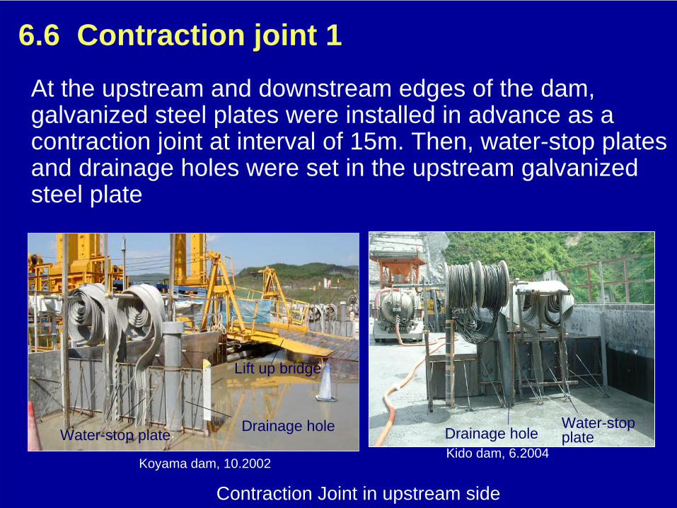
6.6 Contraction joint 1
Contraction Joint in upstream side
Drainage hole
Koyama dam, 10.2002
Water-stop plate
Lift up bridge
At the upstream and downstream edges of the dam, galvanized steel plates were installed in advance as a contraction joint at interval of 15m. Then, water-stop plates and drainage holes were set in the upstream galvanized steel plate
Kido dam, 6.2004Drainage hole
Water-stop plate

Contraction joint 2
After RCD concrete is spread, transverse joints are installed to prevent temperature cracks in the concrete. Contraction joints were cut by a vibratory blade machine and galvanized thin plates were installed in the cutting plane to prevent closing.
Contraction joints are cut by a vibratory blade machine
galvanized thin plates
Bleeding water
After joint cutting
Nagai dam, 9.2005
vibratory blade machine

6.7 Compaction between different concretes
RCD concrete in the internal zone is placed after conventional wet concrete in the external zone. So, the connection zone between RCD concrete and the conventional concrete should be compacted thoroughly by the method like as Figure.
Compaction between different concretes
External concrete
Internal RCD concrete
Backhoe with Immersion
vibrator
4 layers
Nagai dam, 9.2005
Compaction of external concrete
Bleeding water
RCD concrete
External concrete
50cm50cm

6.8 CuringAfter RCD concrete has been placed, it is cured thoroughly in the specified temperature and wetness conditions.Wet curing by ponding or sprinklers is generally applied.Water is sprayed on RCD concrete by sprinklers.
Koyama dam, 10.2002
Wet surface of downstream side
Ponding

6.9 Quality controlVarious quality control measures are executed at RCD dams so
that the quality of materials is monitored carefully. 1. Concrete strength: Once or twice a day, a compressive strength
test is conducted to confirm the strength of RCD concrete.2. Density: There are several methods to check the rate of
compacting of RCD concrete: the number of passes of the vibratory rollers, the RI (Radio Isotope) density meter, or the settlement of the lift during compaction.
3. Water content: The surface water content and grading of aggregates must be monitored with special care since they affect the consistency of RCD concrete.
4. Consistency: The VC test with the standard container is conducted to monitor the consistency of RCD concrete. The test is conducted once every one to two hours.
5. Temperature: The temperature of the mixed concrete is measured periodically to confirm that the concrete is placed according to the temperature restrictions. Thermometers are also embedded in the dam when necessary.

7. New approaches in RCD construction
method
RCD construction method is still progressing with new technologies for the further rationalization.
7.1 Rationalization of external concrete in Kasegawa dam 7.2 Facilitation by precast concrete form 7.3 Construction management by IT (Information Technology)
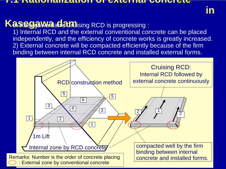
7.1 Rationalization of external concrete in
Kasegawa damIn Kasegawa dam, Cruising RCD is progressing : 1) Internal RCD and the external conventional concrete can be placed independently, and the efficiency of concrete works is greatly increased.2) External concrete will be compacted efficiently because of the firm binding between internal RCD concrete and installed external forms.
2
4
1
3
56
5
3
1
122
Internal zone by RCD concrete
1m Lift
Cruising RCD:Internal RCD followed by
external concrete continuouslyRCD construction method
compacted well by the firm binding between internal concrete and installed forms.Remarks: Number is the order of concrete placing
: External zone by conventional concrete

Compaction works at the end of internal concrete for cruising RCD, Kasegawa dam, 6.2008
Internal RCD concrete
External concrete zone
Lift thickness: h=100cm
Well compacted internal end using a special machine
External concrete zoneConventional concrete in the external zone will be compacted efficiently

7.2 Facilitation by precast concrete formIn Japan, the precast concrete (the concrete structure of pre-fabricated members) have been developed to increase the safety and efficiency in construction works. So far, it has been improved in light-weighting of members, holding of strength and water-tightness at each segment junction, adhesion to the around concrete and concrete placing under precast floors. Recently, external precast forms for the upstream side and downstream side have been developed, and it was confirmed to be efficient in facilitating the concrete works.
Set up of precast formCross section of precast form
Internal CSG
Taiho dam, 10.2003Next layer h=50cm
External concret e
Precast form
h=100cm Precast formPlacement layer of external concrete

7.3 Construction management by IT
In recent years, IT (Information Technology) for the quality management by use of GPS information, latest measuring equipments, and integrated information on design and construction is rapidly progressing. Currently, a full-scale real-time IT system is adopted in Kasegawa dam for quality and quantity management, concrete volume surveying, internal concrete temperature observation, three-dimensional drawings, and labor- saving measures. Photo shows RCD compaction works controlled by IT with GPS positioning and observation of compacted situation by counting.Now, construction managements by IT for concrete dams are scheduled to be adopted in other RCD dams to increase quality and efficiency in Japan.
Vibratory roller SD451 with IT, Kasegawa dam
GPS receiver

Environmental merits of RCD
1. RCD can reduce the CO2 emission.Reduction of unit cement content
Cement : 1.0ton →
CO2 : 0.73ton Unit cement content of RCD is less than conventional dam concrete by 20~50kg/m3.
2. RCD provides greater freedom of the concrete transportation by dump trucks on the placed concrete. Accordingly, by selecting the most suitable systems, there is less damage to the natural environment.

Thank you for your attentions
Muito obrigado pela sua atenção