september 11, 2020 closure
TRANSCRIPT

ROOT CAUSE FAILURE ANALYSIS INVESTIGATION REPORT
Weymouth Compressor Station September 11, 2020 Closure Seal Failure Algonquin Gas Transmission, LLC Subsidiary of Enbridge Inc. Report No.: 10263555-1, Rev. 0 Date: December 22, 2020
Public Version

DNV GL – Report No. 10263555-1, Rev. 0 – www.dnvgl.com Page i
Project name: Root Cause Failure Analysis Investigation Report DNV GL USA, Inc. Oil & Gas Incident Investigation 5777 Frantz Rd. Dublin, OH USA
Report title: Weymouth Compressor Station September 11, 2020 Closure Seal Failure
Customer: Algonquin Gas Transmission, LLC Subsidiary of Enbridge Inc 5400 Westheimer Ct., Houston, TX 77056 USA
Customer contact: Kyle Hart Date of issue: December 22, 2020 Project No.: 10263555 Organization unit: O-AP-RCAReport No.: 10263555-1, Rev. 0
Objective:
Complete a root cause failure analysis facilitated by an independent third party that documents the decision-making process and factors contributing to the September 11, 2020 event at the Weymouth Compressor Station, including findings and lessons learned.
Prepared by: Verified by: Approved by:
Megan Weichel Senior Consultant, Risk Advisory Services
Bjorn Nilberg Senior Principal Consultant, Risk Advisory Services
David Norfleet, Ph.D., P.E. Head of Section, Incident Investigation
Report Contributors:
Kenh Lee, Principal Consultant
Christopher Waghorn, Technical Instrumentation and Electrical Consultant
Copyright © DNV GL 2020. All rights reserved. Unless otherwise agreed in writing: (i) This publication or parts thereof may not be copied, reproduced or transmitted in any form, or by any means, whether digitally or otherwise; (ii) The content of this publication shall be kept confidential by the customer; (iii) No third party may rely on its contents; and (iv) DNV GL undertakes no duty of care toward any third party. Reference to part of this publication which may lead to misinterpretation is prohibited. DNV GL and the Horizon Graphic are trademarks of DNV GL AS.
DNV GL Distribution: Keywords: ☐ OPEN. Unrestricted distribution, internal and external. Incident investigation, BowTie, BSCAT,
Compressor Station, blowdown, shutdown, closure seal, filter separator, sump
☐ INTERNAL use only. Internal DNV GL document.☒ CONFIDENTIAL. Distribution within DNV GL according to
applicable contract.*
☐ SECRET. Authorized access only.
Public Version

DNV GL – Report No. 10263555-1, Rev. 0 – www.dnvgl.com Page ii
Table of contents
EXECUTIVE SUMMARY .................................................................................................................. 1
DEFINITIONS AND LIST OF ACRONYMS .......................................................................................... 4
1 INTRODUCTION .............................................................................................................. 6
2 INVESTIGATION PROCESS ............................................................................................... 7 2.1 DNV GL Mobilization and Initial Information Gathering 7 2.2 Timeline of the Event 9
3 IMMEDIATE / DIRECT CAUSE ANALYSIS .......................................................................... 14
4 ROOT CAUSE FAILURE ANALYSIS WITH BSCATTM .............................................................. 17
5 BARRIER ANALYSIS ...................................................................................................... 21 5.1 Preventive Barriers 23
6 SUMMARY AND CONCLUSIONS ....................................................................................... 30
7 REFERENCES ................................................................................................................ 32
Public Version

DNV GL – Report No. 10263555-1, Rev. 0 – www.dnvgl.com Page iii
List of Tables
Table 1. Summary of Observations .............................................................................................. 14 Table 2: Analysis of Barrier: Learning from Events/Continuous Improvement Process......................... 25 Table 3: Analysis of Barrier: Management of Project Changes .......................................................... 26 Table 4: Analysis of Barrier: Storage Procedures and Requirements ................................................. 27 Table 5: Analysis of Barrier: Commissioning Plan/Procedures .......................................................... 28
List of Figures
Figure 1. Schematic showing the Investigation Process. ................................................................... 7 Figure 2. Timeline of Weymouth Compressor Station Project. .......................................................... 11 Figure 3. Timeline showing key events/activities on the day of the release event, September 11, 2020.
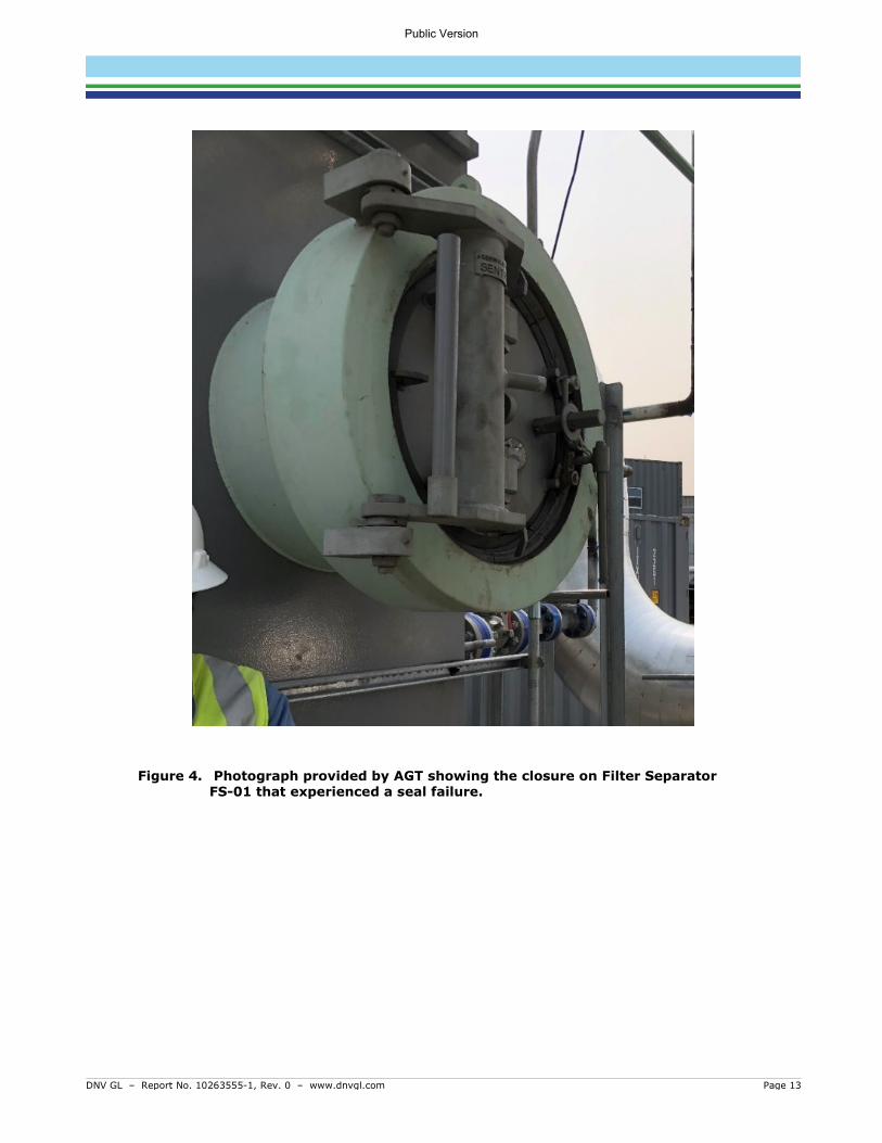
................................................................................................................................. 12 Figure 4. Photograph provided by AGT showing the closure on Filter Separator FS-01 that
experienced a seal failure. ............................................................................................ 13 Figure 5. Photograph provided by AGT showing the failed O-ring. ................................................... 15 Figure 6. Photograph provided by AGT showing a similarly damaged O-ring on a closure door of Filter
Separator FS-02. Desiccant packs can also be seen inside the closure hub. ........................ 16 Figure 7: Comparison of Traditional SCAT and BSCAT Methodologies. ............................................... 18 Figure 8: Typical BowTie Diagram. ............................................................................................... 19 Figure 9: BSCATTM Diagram Legend.............................................................................................. 20 Figure 10: Simplified BSCATTM Diagram for the Event – Preventive Barriers. ..................................... 22
Public Version

DNV GL – Report No. 10263555-1, Rev. 0 – www.dnvgl.com Page 1
EXECUTIVE SUMMARY
DNV GL USA, Inc. (DNV GL) performed a root cause failure analysis (RCFA) for a release that occurred at a closure on the sump of a filter separator on September 11, 2020 during commissioning of the Algonquin Gas Transmission, LLC (AGT)1 Weymouth Compressor Station in Weymouth, Massachusetts. The release event resulted in subsequent isolation of the filter separator and manual blowdown to place the site into a safe state, which resulted in a combined release of approximately of 169,000 standard cubic feet (169 MSCF) of natural gas (13 MSCF released at ground level, 156 MSCF released through the source control silencer). An Amended Corrective Action Order (ACAO) was issued to AGT for a September 30, 2020 event by the Pipeline and Hazardous Materials Safety Administration (PHMSA). Although not required under the ACAO, AGT voluntarily elected to pursue a RCFA for the September 11, 2020 event.
DNV GL provides an independent investigation using specialists trained in investigation techniques, complex technologies, and difficult or challenging environments. The Barrier-based Systematic Cause Analysis Technique (BSCATTM), used to evaluate events, combines traditional technical and management system root cause analysis with modern barrier-based risk assessment.
The 24-inch (NPS 24) subject closure, Sentry™ closure manufactured by National Oilwell Varco (NOV), is a Class 900 Schedule 80, rated for a maximum allowable pressure (MAP) of 2,220 psi at 70°F (2,035 psi at 220°F). The closure is located on the sump of filter separator FS-01, which was built and certified by GasTech Engineering LLC (GasTech) in 2017. The release reportedly occurred at 579 psig during commissioning. Commissioning activities are undertaken to ensure tightness and verify all equipment is prepared and ready for operational readiness.
The objectives of this RCFA were to identify the most probable immediate (direct) cause and root cause(s) of the release event that resulted in the September 11, 2020 release and blowdown at the Weymouth Compressor Station, and document the decision-making process and factors contributing to the event. DNV GL’s work involved reviewing documentation and conducting interviews associated with the design, installation, service, and operational history of the station, including associated procedures and practices. These activities were the main inputs to four (4) causal analysis workshops, facilitated by DNV GL, that utilized the Barrier-based Systematic Cause Analysis Technique (BSCATTM) to document and evaluate the effectiveness of barriers in place to prevent the immediate cause that led to the blowdown event. The team discussed recommended improvements to lower the likelihood of a similar event from occurring in the future.
The conclusions of this RCFA are based on findings from the document review, site visit to the Weymouth Compressor Station, interviews, and BSCATTM workshops facilitated by DNV GL. DNV GL reserves the right to modify or supplement the conclusions represented herein should new information become available.
The results of the investigation determined that the direct cause of the release was a seal failure facilitated by an O-ring that was in place during commissioning that was not intended to experience operational pressure or in-service environments. The operational seal, intended for service, was shipped in a separate box with the closure but was not installed. It was AGT’s belief that the vessels were delivered with operational seals installed based on the experience of the AGT personnel onsite.
1 Algonquin Gas Transmission, LLC is a subsidiary of Enbridge Inc.
Public Version

DNV GL – Report No. 10263555-1, Rev. 0 – www.dnvgl.com Page 2
Analysis of the direct cause identified four (4) primary barriers that could be implemented and/or improved to reduce the likelihood of an event similar to the O-ring failure and subsequent unplanned release of natural gas from occurring in the future:
• Learning from events/continuous improvement process
• Management of project changes
• Storage procedures and requirements
• Commissioning plan/procedures (pre-use inspection)
The lessons learned and corresponding recommendations for improvement pertaining to these four barriers are discussed below.
1. Improvement of Learning from Events Process
Recent enhancements to the Company requirements and investigation procedures require steps to be taken to communicate lessons learned and implement changes that should be taken to lower the likelihood of a repeat occurrence at the event site/location as well as other relevant sites/locations throughout the organization. By reviewing and verifying how effective the communication of high value learning events and incidents is throughout the Company and ensuring future cross-communication among locations and organizational groups, the learning from events process barrier can be strengthened.
2. Effective Management of Changes to Projects
The standards, processes, and procedures for project management and management of change should be evaluated to ensure the risks associated with project delays are evaluated, communicated, and managed appropriately. Enhancements to such documents will help to address the considerations that should be made when changes are made to projects, such as long-term delays.
When changes are made to projects, guidance should be in place to help ensure items, such as hazard identification, extended storage of components, and communication of special circumstances to vendors will be addressed in future projects.
Communicating the risks identified through this recommendation to vendors will help AGT develop plans/paths forward to understand the measures vendors take to store AGT’s equipment during the project delays.
3. Clear Specifications and Communication with Vendors
Currently, the specifications given to vendors by AGT are focused on the requirements for assembly and testing of components; however, they do not include requirements for how the components are marked, packaged, transported, and/or stored by the vendor.
The standards, processes, and procedures for supply chain management and project management should be reviewed and revised to ensure the risks identified within project teams are communicated from the project to supply chain personnel. This will provide AGT with further assurance that risks associated with storage at vendor sites during future delays are appropriately managed.
Public Version

DNV GL – Report No. 10263555-1, Rev. 0 – www.dnvgl.com Page 3
Enhancements to such documents will help ensure the following items are addressed in future projects:
• Identification of hazards and risks associated with long-term storage of components and equipment, and measures to manage the risks.
• Clear specifications and requirements for what information should be communicated to vendors and by which method(s) it should be conveyed.
• Identification of special circumstances and development of processes associated with vendors for assembly, testing, safe packaging, transportation, and storage of equipment.
4. Revisions and Enhancements to the Commissioning Manual and associated Requirements
The Company requirements and the Commissioning Manuals should be reviewed to determine what revisions are appropriate to ensure they adequately address vessels and filters. The requirements should ensure that vessel closure seals are inspected prior to vessel installation and that consumable parts (seals, O-rings, gaskets) shipped with closures and other serviceable attachments are consistent with the nameplate and specified purchase order or bill of materials. The requirements should also ensure the consumable parts are made of appropriate materials for normal operation in the operating environment. In addition to modifying the Commissioning Manual, other enhancements should be considered for the Pre-startup Safety Review (PSSR) procedure to verify these activities have been completed during commissioning.
Public Version

DNV GL – Report No. 10263555-1, Rev. 0 – www.dnvgl.com Page 4
DEFINITIONS AND LIST OF ACRONYMS Definitions of the terms and acronyms used with the BSCAT methodology are provided in the following table.
Term Definition
Barrier Design features, engineered systems, or administrative controls that prevent the causes or mitigate the consequences of a deviation from normal operation/intent.
Basic Cause (BC) A fundamental, underlying, system-related reason why an incident or event occurred that identifies a correctable failure(s) in management systems. There is typically more than one root cause for every incident. Also referred to as root cause or underlying cause.
Management of Change Process
Documentation of the steps involved to ensure the safe startup and operation of a new facility
Consequence An event or chain of events that result from the release of a hazard.
Evidence Data on which the investigation team will rely for subsequent analysis, testing, reconstruction, corroboration, and conclusions.
Immediate Cause (IC)
A cause where a substandard act was performed or a substandard condition existed. Also referred to as direct cause.
Lessons Learned The application of knowledge gained from past incidents, near misses, or other events in association with the goal of preventing similar events from occurring in the future.
Mitigative Barrier Barriers to the right of the event (after it has happened). They reduce the severity of the consequence event. Mitigation barriers are sometimes referred to as “contingencies” or “recovery measures.”
Preventive Barrier Barriers to the left of the event (before it has happened). They reduce the likelihood of the event. Preventive barriers are sometimes referred to as “controls.”
Root Cause A fundamental, underlying, system-related reason why an incident or event occurred that identifies a correctable failure(s) in management systems. There is typically more than one root cause for every incident. Also referred to as underlying cause.
Root Cause Failure Analysis
A formal investigation method that attempts to identify and address the management system failures that led to an incident or event. These root causes often are the causes, or potential causes, of other seemingly unrelated events. Identifies the underlying reasons the event was able to occur so that workable corrective actions can be implemented to help prevent recurrence of the event (or occurrence of similar events).
Threat A possible cause that will potentially release a hazard and produce a top event.
Top Event Chosen credible scenario that is associated with the release of the hazard.
Acronym Meaning
ACAO Amended Corrective Action Order
AGT Algonquin Gas Transmission, LLC
BC Basic Cause
BSCAT Barrier-based Systematic Causal Analysis Technique
DNV GL DNV GL USA, Inc.
ESD Emergency Shutdown
Public Version

DNV GL – Report No. 10263555-1, Rev. 0 – www.dnvgl.com Page 5
Acronym Meaning
FS Filter Separator
IC Immediate Cause
ISRS International Sustainability Rating System
JSA Job Safety Analysis
MOC Management of Change
NTP Notice to Proceed
MSCF Thousand Standard Cubic Feet
OEM Original Equipment Manufacturer
PHMSA Pipeline and Hazardous Materials Safety Administration
PSSR Pre-startup Safety Review
QA/QC Quality Assurance/Quality Control
RCFA Root Cause Failure Analysis
SCAT Systematic Causal Analysis Technique
Public Version

DNV GL – Report No. 10263555-1, Rev. 0 – www.dnvgl.com Page 6
1 INTRODUCTION DNV GL USA, Inc. (DNV GL) performed a root cause failure analysis (RCFA) for a release that occurred at a closure on the sump of a filter separator on September 11, 2020 during commissioning of the Algonquin Gas Transmission, LLC (AGT)2 Weymouth Compressor Station in Weymouth, Massachusetts. The release event resulted in subsequent isolation of the filter separator and manual blowdown to place the site into a safe state, which resulted in a combined release of approximately of 169,000 standard cubic feet (169 MSCF) of natural gas (13 MSCF released at ground level, 156 MSCF released through the source control silencer). An Amended Corrective Action Order (ACAO) was issued to AGT for a September 30, 2020 event by the Pipeline and Hazardous Materials Safety Administration (PHMSA). Although not required under the ACAO, AGT voluntarily elected to pursue a RCFA for the September 11, 2020 event.
DNV GL provides an independent investigation using specialists trained in investigation techniques, complex technologies, and difficult or challenging environments. The Barrier-based Systematic Cause Analysis Technique (BSCATTM), used to evaluate events, combines traditional technical and management system root cause analysis with modern barrier-based risk assessment.
The 24-inch (NPS 24) subject closure, Sentry™ closure manufactured by National Oilwell Varco (NOV), is a Class 900 Schedule 80, rated for a maximum allowable pressure (MAP) of 2,220 psi at 70°F (2,035 psi at 220°F). The closure is located on the sump of filter separator FS-01, which was built and certified by GasTech Engineering LLC (GasTech) in 2017. The release reportedly occurred at 579 psig during commissioning. Commissioning activities are undertaken to ensure tightness and verify all equipment is prepared and ready for operational readiness.
On October 12, 2020 personnel from DNV GL mobilized an investigation team to determine the initiating event (immediate cause) that led to the release event and begin collecting evidence (documentation, interviews, etc.) for the RCFA. Two members of DNV GL’s team travelled to Waltham, Massachusetts, and spent the week of October 12, 2020 at an AGT office in Waltham, including two days at the Weymouth Compressor Station site.
The objectives of this RCFA were to identify the most probable immediate (direct) cause and root cause(s) of the release event that resulted in the September 11, 2020 release and blowdown at the Weymouth Compressor Station, and document the decision-making process and factors contributing to the event. DNV GL’s work involved reviewing documentation and conducting interviews associated with the design, installation, service, and operational history of the station, including associated procedures and practices. These activities were the main inputs to four (4) causal analysis workshops, facilitated by DNV GL, that utilized the Barrier-based Systematic Cause Analysis Technique (BSCATTM) to document and evaluate the effectiveness of barriers in place to prevent the immediate cause that led to the blowdown event. The team discussed recommended improvements to lower the likelihood of a similar event from occurring in the future.
The conclusions of this RCFA are based on findings from the document review, site visit to the Weymouth Compressor Station, interviews, and BSCATTM workshops facilitated by DNV GL. DNV GL reserves the right to modify or supplement the conclusions represented herein should new information become available.
2 Algonquin Gas Transmission, LLC is a subsidiary of Enbridge Inc.
Public Version

DNV GL – Report No. 10263555-1, Rev. 0 – www.dnvgl.com Page 7
2 INVESTIGATION PROCESS DNV GL’s investigation process began with initial familiarization of the event through telephone calls and initial document review. Upon arrival in Massachusetts, the DNV GL team reviewed documentation and conducted interviews to gain further understanding of the sequence of events. As the investigation progressed, additional documents were provided by AGT, and DNV GL conducted follow-up interviews to ensure adequate information was available to verify the direct cause. The team utilized the knowledge gained in the early steps of the process to conduct causal analysis sessions, using DNV GL’s BSCATTM methodology, and identify recommended improvements. Figure 1 provides a schematic overview of the investigative process utilized for this investigation.
Figure 1. Schematic showing the Investigation Process.
2.1 DNV GL Mobilization and Initial Information Gathering Many of the interviews and initial document review were performed at the AGT Waltham office before the DNV GL team visited the Weymouth Compressor Station, which allowed the team to be prepared with questions for site personnel and specific areas of interest during the site activities.
2.1.1 Familiarization At the start of the investigation, DNV GL reviewed documentation provided by AGT related to the September 11, 2020 event. DNV GL then conducted interviews both onsite and via telephone with key AGT personnel and contractors during the week of October 12, 2020, to gain insight into activities and observations made before, during, and after the release event, as well as clarify any questions related to the reviewed documentation. The documents and interviews became the main inputs to BSCATTM workshops. The interviews involved four (4) AGT employees and two (2) contractors in the following roles:
• Functional Coordinator
• Area Supervisor
• Area Safety Lead
• Site Safety Inspector
• Project Engineer
• Commissioning Lead
Familiarize
Visit AGT Office and Weymouth
Site
Interview Personnel
Verify Direct Cause
Conduct Causal
Analysis (BSCAT)
Conclusion/ Recom-
mendations
Document Review and Timeline Development
Public Version

DNV GL – Report No. 10263555-1, Rev. 0 – www.dnvgl.com Page 8
2.1.2 Document Review The DNV GL investigation team was supplied drawings, manuals, procedures, and pictures and briefed by AGT project engineers on the Weymouth Compressor Station site design philosophy and its operation and provided answers to initial questions from the investigation team. Additional documentation was provided by AGT throughout the investigation, as requested by the DNV GL team and/or as AGT identified additional relevant documentation.
2.1.3 Interviews Personnel relevant to the event were interviewed during the site visit. Personnel who were not physically present on site were interviewed over the phone.
The DNV GL team asked each interviewee to describe his or her observations the day of the event in their own words. Follow-up questions were asked to clarify the following details:
• How were you made aware of the event?
• Where were you during the event?
• What did you observe during and after the event?
• Describe your involvement after the event.
Collating the information from the interviews, cell phone and data logs, the DNV GL investigators were able to corroborate and confirm observations and details from different perspectives, which aided in generating a timeline and substantiating key timeline events.
If the team encountered information gaps or uncertainties related to specific information gathered from an interview or document review, follow-up interviews were conducted. Also, in some cases, additional interviews were conducted to seek further clarity.
2.1.4 Weymouth Site Visit The team was given a safety briefing at the AGT Waltham office prior to departing for Weymouth, where the DNV GL investigation team was given a tour of the Weymouth Compressor Station site by AGT. The purpose of the site was for the DNV GL team to become familiar with the site, with focus on filter separator FS-01 and its surroundings, including piping, walkways, vessels, shutdown and isolation valves. The investigation team was provided full access to the site by AGT.
Public Version

DNV GL – Report No. 10263555-1, Rev. 0 – www.dnvgl.com Page 9
2.2 Timeline of the Event The interviews, as well as AGT-provided information, were used to create two timelines: the project overview timeline shown in Figure 2 and the event timeline shown in Figure 3. A color-coding legend for each timeline is presented in the figures. In some cases, specific times were available, and in cases where a specific time was not available, an approximate time was used.3
Based on the timeline, the most likely sequence of events was established and areas for further investigation were identified.
2.2.1 Activities Leading to the Event Figure 2 provides an overview of key dates for the Weymouth Compressor Station Project. The Weymouth Compressor Station was initially designed in February 2015 as a part of the Atlantic Bridge Project to increase natural gas pipeline capacity to the New England states and the Canadian Maritime provinces. The Compressor Station is located in northern Weymouth, Massachusetts, a city located south of Boston. The construction drawings were issued in July 2016 and construction on the project commenced until January 2017, when the project timeline was delayed, and equipment was put into long-term storage. The Federal Energy Regulatory Commission (FERC) issued the Notice to Proceed (NTP) in November of 2019, and construction restarted in December 2019 with the intention to place the station into service in October 2020. From July to September various commissioning activities were undertaken at the site, including quality assurance (QA) inspections.
Filter separator FS-01 was delivered to the Weymouth Compressor Station from long-term storage on the vendor’s site in February 2020 for installation. The filter separator was subjected to a commissioning pressure pack to 50 psig and was leak checked on September 9 and 10, 2020. No leaks were identified.
During commissioning activities on September 11, 2020, a seal on the closure door of the filter separator FS-01 failed, resulting in venting natural gas from the station. Specific activities related to this event are detailed below and illustrated on the timeline in Figure 3.
On the day of the event, a Job Safety Analysis (JSA) was performed at approximately 7:00 a.m. Following the JSA, pressurization of the Compressor Station was initiated; this was a manual process that started at 5 psig and was completed when the pressure reached 579 psig at approximately 8:00 a.m. At this time (approximately 8:00 a.m. and shortly afterward) many activities were being performed, including cleaning of the vessel associated with the vent source control silencer. The cleaning activity required the vessel to be isolated, which disabled the gas operated valves, requiring the valves to be manually operated.
At 8:45 am, the seal for the sump closure door on filter separator FS-01 failed, releasing high pressure natural gas from a localized area between the filter separator closure hub and mating door. Figure 4 is a photograph taken by AGT showing the closure door that experienced the seal failure. A total volume of 169 MSCF of natural gas was released (13 MSCF released at ground level, 156 MSCF released through the source control silencer). Immediately after the seal failure, onsite personnel manually closed the filter separator inlet valve FSI-01 and outlet valve FSO-01 to isolate FS-01 and isolate the release location; however, valve closure could not be confirmed, because of the proximity of the release to the valve position indicators. Therefore, the release area was evacuated at 8:48 a.m. and by 8:50 a.m. it was determined that it was
3 Approximate times are indicated in italic text.
Public Version

DNV GL – Report No. 10263555-1, Rev. 0 – www.dnvgl.com Page 10
necessary, for safety reasons, to direct the inventory through the source control silencer by manually opening station blowdown valves ESD-1, ESD-2, ESD-3, and ESD-4. At 8:51 a.m., all four (4) of the valves were opened by Operations. This diverted the remaining inventory of natural gas to the venting system, which released to a safe area as intended and according to design. An observation was made at the same time (8:51 a.m.) that residual pressure was still trapped in filter separator FS-01, indicating successful closure of valves FSI-01 and FSO-01 and isolation of filter separator FS-01. By 8:52 a.m., staff had mustered near a courtyard wall to account for personnel.
Approximately 15 minutes later, at 9:05 a.m., personnel identified the likely release origin as the sump closure seal on filter separator FS-01. Filter separator FS-01 was depressurized at 9:30 a.m., and by 10:30 a.m., the sump closure door was opened. AGT personnel verified that a black polymer closure seal (O-ring) had failed.
At 10:48 a.m., AGT began sourcing a replacement closure seal by calling other AGT locations and facilities that use the same type of Sentry closure and requesting the construction team to contact the original equipment manufacturer (OEM) for spare closure seals.
By 11:21 a.m. a spare seal was located at the Dighton, MA office and immediate delivery was arranged. The seals from Dighton arrived at 12:00 p.m. An inspection of the replacement seal determined that it was the incorrect size and could not be installed. At approximately the same time (12:00 p.m.), AGT personnel contacted the vendor to discuss the situation, and soon after, the correct seal was located onsite by AGT’s Construction group. Concurrent to these activities, the opened filter separator FS-01 sump was cleaned and prepared for installation of a new 24-inch diameter seal. While cleaning, desiccant bags were discovered inside the sump. Desiccant bags are placed within components during shipping and storage to remove moisture, minimizing adverse effects such as corrosion.
By 3:30 p.m., all four (4) of the 24-inch diameter lower door seals on filter separator FS-01 and FS-02 were installed (two seals per vessel). One 40-inch diameter upper door seal on filter separator FS-01 was installed to replace an incorrect seal. A second 40-inch seal was ordered and replaced 3 days later on FS-02.
Public Version

DNV GL – Report No. 10263555-1, Rev. 0 – www.dnvgl.com Page 11
Green = Construction Activities Purple = Permitting and Regulatory Grey/Black = Commissioning Activities Red = Event
Figure 2. Timeline of Weymouth Compressor Station Project.
2/1/2015 9/11/20201/1/2016 1/1/2017 1/1/2018 1/1/2019 1/1/2020
7/28/2016Drawings Issued for Construction
2/22/2016File Air Permit
7/12/2019Receive Air Permit 11/27/2019
Receive FERC NTP
12/3/2019Construction Restarts
7/16/2020 - 9/12/2020Commissioning
2/11/2015Initial Station Design
and Project Start
EventConstruction Activities
Permitting and Regulatory
Commissioning Activities
9/11/2020Event
Release and Manual Blowdown1/1/2017Decision to put equipment in
long-term storage due to delay
11/12/2019Remaining permits
obtained
Public Version

DNV GL – Report No. 10263555-1, Rev. 0 – www.dnvgl.com
Purple = Normal Planned Activities Red = Event Blue = Response Green = Repair
Figure 3. Timeline showing key events/activities on the day of the release event, September 11, 2020.
06:00 16:0007:00 08:00 09:00 10:00 11:00 12:00 13:00 14:00 15:00
12:00Correct seal was determined to be onsite
through conversation with Construction group.
15:30One 40" upper seal on the filter separator Sentry
closures FS-01 was installed to replace the incorrect seal.09:30
Evacuated vessel.
08:48The area was evacuated for safety prior to initiating blowdown because the area where work was being done was near where the blowdown would occur.
15:30All 4 24" seals on the filter separator sump Sentry
closures FS-01 and FS-02 were installed (2 seals per vessel).
08:50All 4 valves open.
12:00Initial opening of FS-01 for cleaning
prior to installing new 24" seal. Also found dessicant to be inside
the vessel at this time.
Response
Event
Normal Planned Activities
Repair
Repair08:45
Activities to isolate the valves (filter separator inlet FSI-01 and outlet FSO-01).
Unable to verify valve position due to location in gas stream.
08:51Verified presence of
all personnel.
08:51Confirmation of pressure in FS-01 indicates vessel
is isolated.
11:21Seal en route to facility
from nearby Dighton office.12:00
Seal arrived from Dighton. Inspected seal and it becameevident that the seals were not similar (one was hollow, one
was solid). Realized the newly arrived seal could not beinstalled.
9/9/20 to 9/10/20Filter separator experienced
commissioning pressure pack to 50 psig.
07:00The day's JSA was conducted and
began initial pressurization of station (beginning at 5 psi) - manual process. 08:00
Pressurization complete (579 psi).08:00
Activity ongoing from 8:00 until the event. Vessel (blowdown stack) cleaning being conducted.
Required vessel to be isolated, which prevented ability to use any gas operated valves -
required to manually stroke valves.
08:45Event
O-ring on FS-01 leaks resulting in 169 mscf gas released.
10:30Opened vessel and verified
there was a failed o-ring.
10:48Briefed construction team
and asked them to contact the OEM for spare o-ring(s).
11:52Construction team identified which seal should be installed
10:48Began looking for/calling other locations to find a new o-ring
(same type of Sentry closure used elsewhere, so similar style seal is used
in other facilities).
09:05Identified the likely leak
site as the sump closure seal on FS-01.
08:50Determined it was necessary to manually open 4 station blowdown valves (dump the system).
ESD-1, ESD-2, ESD-3, ESD-4. This was not a manual ESD; rather it was a blowdown.
Public Version
DNV GL – Report No. 10263555-1, Rev. 0 – www.dnvgl.com Page 13
Figure 4. Photograph provided by AGT showing the closure on Filter Separator FS-01 that experienced a seal failure.
Public Version
DNV GL – Report No. 10263555-1, Rev. 0 – www.dnvgl.com Page 14
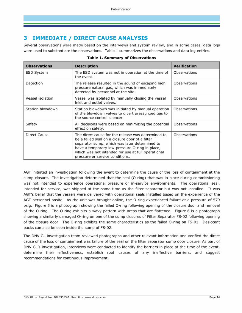
3 IMMEDIATE / DIRECT CAUSE ANALYSIS Several observations were made based on the interviews and system review, and in some cases, data logs were used to substantiate the observations. Table 1 summarizes the observations and data log entries.
Table 1. Summary of Observations
Observations Description Verification
ESD System The ESD system was not in operation at the time of the event.
Observations
Detection The release resulted in the sound of escaping high pressure natural gas, which was immediately detected by personnel at the site.
Observations
Vessel isolation Vessel was isolated by manually closing the vessel inlet and outlet valves.
Observations
Station blowdown Station blowdown was initiated by manual operation of the blowdown valves to divert pressurized gas to the source control silencer.
Observations
Safety All decisions were based on minimizing the potential effect on safety.
Observations
Direct Cause The direct cause for the release was determined to be a failed seal on a closure door of a filter separator sump, which was later determined to have a temporary low-pressure O-ring in place, which was not intended for use at full operational pressure or service conditions.
Observations
AGT initiated an investigation following the event to determine the cause of the loss of containment at the sump closure. The investigation determined that the seal (O-ring) that was in place during commissioning was not intended to experience operational pressure or in-service environments. The operational seal, intended for service, was shipped at the same time as the filter separator but was not installed. It was AGT’s belief that the vessels were delivered with operational seals installed based on the experience of the AGT personnel onsite. As the unit was brought online, the O-ring experienced failure at a pressure of 579 psig. Figure 5 is a photograph showing the failed O-ring following opening of the closure door and removal of the O-ring. The O-ring exhibits a wavy pattern with areas that are flattened. Figure 6 is a photograph showing a similarly damaged O-ring on one of the sump closures of Filter Separator FS-02 following opening of the closure door. The O-ring exhibits the same characteristics as the failed O-ring on FS-01. Desiccant packs can also be seen inside the sump of FS-02.
The DNV GL investigation team reviewed photographs and other relevant information and verified the direct cause of the loss of containment was failure of the seal on the filter separator sump door closure. As part of DNV GL’s investigation, interviews were conducted to identify the barriers in place at the time of the event, determine their effectiveness, establish root causes of any ineffective barriers, and suggest recommendations for continuous improvement.
Public Version

DNV GL – Report No. 10263555-1, Rev. 0 – www.dnvgl.com Page 15
Figure 5. Photograph provided by AGT showing the failed O-ring.
Public Version

DNV GL – Report No. 10263555-1, Rev. 0 – www.dnvgl.com Page 16
Figure 6. Photograph provided by AGT showing a similarly damaged O-ring on a closure door of Filter Separator FS-02. Desiccant packs can also be seen inside the closure hub.
Public Version

DNV GL – Report No. 10263555-1, Rev. 0 – www.dnvgl.com Page 17
4 ROOT CAUSE FAILURE ANALYSIS WITH BSCATTM DNV GL used a systematic root cause failure analysis methodology to investigate the underlying weaknesses in the management system (i.e., procedures and processes) related to the September 11, 2020 event. When investigating operational incidents and undesired events, the use of a systematic approach helps ensure that the underlying weaknesses in the management system are identified and addressed. Without a systematic approach, too much reliance may be placed on the specific knowledge, experience and personal viewpoint of the person carrying out the investigation, which may result in different investigators identifying different causes. An unstructured approach can also result in inappropriately blaming either the equipment or the person without consideration of the underlying, system related root causes. By identifying opportunities for improvement in the management systems, more effective solutions can be developed that will result in more effective barriers for the prevention of recurrences.
4.1.1 BSCATTM Methodology DNV GL’s barrier-based systematic causal analysis technique (BSCATTM) is a well-established, industry accepted methodology for investigating accidents and identifying root causes. The predecessor, SCAT, was originally developed in the 1980s as part of DNV GL’s International Safety Rating System (ISRSTM). [1] The methodology has been used for decades by DNV GL and client companies around the world to evaluate many serious incidents across different industries.
BowTie diagrams are used to identify the barriers that are in place to prevent threats from escalating into top events and the barriers that are in place to mitigate consequences following a top event. This analysis can be performed before an event to help assess the barriers that are in place and their current state. BowTies can also be created following an undesired event to analyze the system’s barriers at the time of the event.
Systematic Causal Analysis Technique (SCATTM) is a root cause analysis approach that uses standardized causation descriptions to describe the immediate (direct) and basic causes helping incident investigators to identify weak areas of the management system. The standard causation descriptions help to categorize commonalities that can be tracked to prioritize the areas of the management system that are related to root causes of the incident.
BSCATTM applies the SCATTM model to each barrier as opposed to the incident as a whole. This method results in a review of the effectiveness of the individual barriers identified in the assessment. Figure 7 depicts the basic approach of how BSCATTM is applied to address the controls prior to an event and after the event has occurred, and it also shows a comparison of the Traditional SCATTM methodology compared to the BSCATTM methodology. Note that the terms “control” and “barrier” are used interchangeably in this process.
Public Version

DNV GL – Report No. 10263555-1, Rev. 0 – www.dnvgl.com Page 18
Figure 7: Comparison of Traditional SCAT and BSCAT Methodologies.
The BSCATTM process involves the following steps:
a) Evidence Capture and Review – Collecting information pertaining to the event through interviews of the people involved and reviews of documents related to the event. The majority of the evidence for this investigation was obtained through interviews and document review.
b) Timeline Development – Creation of a timeline of events leading up to and during the event. The timeline was developed with AGT from the knowledge of site personnel.
c) Barrier Identification – A BowTie is created for the threat that escalated to the main event. The barriers in place, as well as those that could have been, are identified at this time.
d) Barrier Type– The types of barriers (e.g., administrative control, design, etc.) are determined with the team.
e) Causal Analysis – The SCATTM process is then applied to each barrier identified as failed, missing, or insufficient.
Consequence Consequence
Public Version

DNV GL – Report No. 10263555-1, Rev. 0 – www.dnvgl.com Page 19
4.1.2 BSCATTM Workshop Team DNV GL facilitated four BSCAT sessions by remote call-in with the AGT team on the following dates:
• November 13, 2020
• November 30, 2020
• December 1, 2020
• December 3, 2020
A balanced, cross-functional team was assembled for the BSCATTM workshop, which included individuals with extensive knowledge of the Weymouth Compressor Station. The DNV GL facilitator of the workshop has had formal training in conducting root cause analyses using the BSCATTM methodology, and some AGT team members have also had training in the methodology.
During the BSCATTM sessions, the team referred to documents, data, and interview information from earlier stages of the investigation to discuss the scenarios and status of each barrier.
4.1.3 BowTie Diagram Development In the BowTie diagram (Figure 8), the undesired event being investigated - the top event - is shown in the center as the “knot.” Threats that can, or did, lead to the top event are shown to the left-hand side of the knot. The possible consequences are shown on the right-hand-side of the top event.
Threats, as well as the consequences, can be controlled with the use of “barriers.” Barriers are shown on the BowTie diagram as blocks between the threats and the top event (i.e., preventive barriers) and between the top event and the consequences (i.e., mitigation barriers). Barriers can be physical barriers, such as hardware, or procedural barriers, such as procedures and plans.
Figure 8: Typical BowTie Diagram.
Public Version

DNV GL – Report No. 10263555-1, Rev. 0 – www.dnvgl.com Page 20
4.1.4 BSCAT Legend To better understand the discussion that follows, Figure 9 presents a legend showing symbols used in the BSCATTM analysis. This figure shows the Initiating Event / Cause in the blue box to the left side – this starts the event sequence. The red and orange box in the center, the Top Event, represents the time when a loss of control occurs – for this investigation the Top Event is selected as a Loss of Containment at Filter Separator #1. To each side of the Top Event are barriers that should have been able to prevent the Top Event from occurring (on the left side of the diagram) or mitigate the event (to the right side of the Top Event).
Four barrier symbols are displayed in Figure 9:
1. Missing: should/could have been present but was missing at the time of the event.
2. Failed: failed in its function during the time of the event.
3. Insufficient: functioned in the event but had some weaknesses or only partially worked OR in place but not appropriate to prevent incidents in the future.
4. Effective: worked as expected and was effective.
Figure 9: BSCATTM Diagram Legend.
4.1.5 SCATTM Analysis For each barrier found to be missing, failed, or insufficient, the SCATTM process was applied to determine the immediate and basic causes of the barriers’ failure or inadequacy. An assessment of the primary barriers as they pertained to the Weymouth vessel seal failure and blowdown event is provided in Section 5. By evaluating all potential barriers individually, and the root causes of why those barriers failed or were ineffective, BSCATTM provides a broad view of the event and associated areas of improvement for the management system. This approach provides AGT with the opportunity to make improvements that are specifically targeted to preventing similar events across the organization.
Public Version

DNV GL – Report No. 10263555-1, Rev. 0 – www.dnvgl.com Page 21
5 BARRIER ANALYSIS The BSCATTM methodology was applied to each failed or inadequate barrier to determine the immediate and basic causes of each identified barriers’ failure or inadequacy. When the closure for filter separator FS-01 was inspected after the event, the failed seal was visibly damaged, and it was removed. In addition, the seal on the other filter separator (FS-02) was also visibly damaged, but did not lose pressure containment (Figure 6). The direct cause of the event was determined to be the vessel seal failure.
The combined DNV GL and AGT team discussed each barrier as described in Section 5.1.
The conclusions of this investigation are based on an assessment of the preventive barriers (intended to reduce the likelihood of an event) illustrated in the simplified diagram depicted in Figure 10. For each barrier, the Immediate/Direct Causes, Basic/Root Causes and Recommendations are summarized.
It should be noted that the terminology for each immediate cause and basic cause, e.g., “inadequate,” “inefficient,” “lack of,” or “failure of,” is standardized for use across all industries. For this reason, additional information is provided in the diagram in the appendix to expand on the reasons for the barriers performing in an ineffective manner. Section 5.1 includes additional information regarding each of the barriers analyzed as part of this investigation.
The complete BSCATTM diagram, which can be found in Appendix A, includes the full causation for each barrier that contributed to the event.
Public Version

DNV GL – Report No. 10263555-1, Rev. 0 – www.dnvgl.com Page 22
Figure 10: Simplified BSCATTM Diagram for the Event – Preventive Barriers.
Vessel Closure Seal Failure
Loss of Containment at
Filter Separator #1Learning from Events/
Continuous Improvement
Process
Management of Project Changes
Storage procedures and requirements
Verification of materials upon receipt onsite
Pre-startup Safety Review
Commissioning Plan/Procedures
(Pre-use Inspection)
Handover from Projects Group to Operations Group
Public Version

DNV GL – Report No. 10263555-1, Rev. 0 – www.dnvgl.com Page 23
5.1 Preventive Barriers During the BSCATTM workshops, the team members identified the barriers that were in place at the time of the event as well as those that could have been in place to prevent the event from occurring.
A total of seven (7) preventive barriers were identified for the vessel seal failure:
1. Learning from Events/Continuous Improvement Process 2. Management of Project Changes 3. Storage Procedures and Requirements 4. Verification of Materials upon Receipt Onsite 5. Pre-startup Safety Review 6. Commissioning Plan/Procedures (pre-use inspection) 7. Handover from Projects Group to Operations Group
Three (3) of the barriers listed above were determined to be non-causal, meaning they were effective during the event, or they did not contribute to the event. The remaining four (4) barriers, indicated with yellow highlighting in the above list, were determined to contribute to the event; therefore, the discussion sections for each of the causal barriers include a table outlining the barrier’s status for the event, as well as the immediate and basic causes (and BSCATTM coding) of their failures if they were not effective during the event. It should be noted that the BSCATTM coding and wording is intended for general use; therefore, there is additional information in the table, as well as the section’s discussion, to further explain each barrier’s status. Finally, any recommendations for improvement are noted at the end of each table. The preventive barriers are detailed in the following sections.
5.1.1 Non-causal Barriers The following three barriers were identified by the team to be non-causal to the September 11, 2020 event:
1. Verification of Materials upon Receipt Onsite
Verification of materials was performed correctly and in accordance with the AGT procedures and requirements. While this process is intended to verify that the materials sourced were delivered, it is not intended to inspect whether the materials meet specifications. In this case, the AGT representatives identified that one set of operational seals was missing, which they communicated to the vendor. The vendor then sent the second set of operational seals. The discussion of the Commissioning Plan/Procedures barrier in Section 5.1.5 explores the events that followed after materials were received onsite.
2. Pre-startup Safety Review (PSSR)
The PSSR is a systematic and thorough check of a process prior to the introduction of a highly hazardous chemical to a process. The PSSR confirms the following: Construction and equipment are in accordance with design specifications; safety, operating, maintenance, and emergency procedures are in place and are adequate; a process hazard analysis has been performed for new facilities and recommendations have been resolved or implemented before startup, and modified facilities meet the management of change requirements; and training of each employee involved in operating a process has been completed. [2]
Public Version

DNV GL – Report No. 10263555-1, Rev. 0 – www.dnvgl.com Page 24
PSSR was begun prior to gas handling/commissioning and signed off on 9/11/2020. AGT’s PSSR essentially has three stages (pre-gas, post-gas, pre-turnover). One part is conducted before first gas is introduced. The second part is done after commissioning, and additional PSSR tasks are done before handover to Operations.
3. Handover from Project Group to Operations Group
Good industry practices for proper handover from the project team to Operations personnel provide assurance that Operations understands the final as-built design, has appropriate procedures and maintenance strategies, has been given all relevant documentation and drawings, and are aware of the risks associated with the asset. Planning for eventual handover should begin early in the project to ensure a gradual transfer of knowledge. A formal handover process includes requirements for early involvement of Operations, Maintenance and other critical functions in the project development, assessment of operational risks, incorporation of lessons learned from previous projects or events, and effective development of documentation and procedures. These elements can support safe and effective operation when the project is complete.
AGT’s process for handover from the project team to Operations is gradual, and the project was not to the point of full handover at the time the event occurred. The Operations group worked with the Commissioning team, which began the handover process, and both groups were then involved in commissioning and PSSR.
Public Version

DNV GL – Report No. 10263555-1, Rev. 0 – www.dnvgl.com Page 25
5.1.2 Learning from Events/Continuous Improvement Process
During a BSCATTM session, the team discussed a previous, similar event that occurred at a NEXUS natural gas Compressor Station in Hanoverton, OH. On September 6, 2018, a filter separator was being placed into service, following an unanticipated project extensions and extended storage with nitrogen blanketing, when the upper door closure seal failed. It was discovered that the failed seal was intended for low-pressure nitrogen storage and was not replaced with the correct operational seal designed for high pressure operation.
According to the AGT team, since the time of the 2018 event, a more complete learning from events process has been implemented. The new investigation procedures require steps to be taken to communicate lessons learned and implement changes that should be taken to lower the likelihood of a repeat occurrence at the event site/location as well as other relevant sites/locations throughout the organization. These steps were not taken following the Hanoverton event; therefore, the barrier was insufficient to prevent the Weymouth event. Going forward, the new process includes requirements that should strengthen the barrier. An additional recommendation was made to further improve the process.
Table 2 summarizes the barrier of the Learning from Events/Continuous Improvement Process.
Table 2: Analysis of Barrier: Learning from Events/Continuous Improvement Process
Barrier: Learning from Events/Continuous Improvement Process
Status for Event: Insufficient
Immediate Cause: IC18. Failure to Identify Hazard
A previous event occurred at a similar facility. The process for investigating and communicating near misses and incidents did not identify this event for evaluation or shared learnings.
Basic Cause: BC18.3. Inadequate Transfer of Information between Processes/Organizational Units
At the time of the event (2018), the process for investigating near misses and incidents was not as robust as it is today. The current investigation procedures could have helped to ensure learnings were communicated and actions implemented to prevent similar events in the future.
Recommendation #1:
Verify how effective the communication of high value learning events and incidents is throughout the Company and ensure future cross-communication among locations and organizational groups. The Safety group sends out weekly flash reports with communication of incidents from the week and any high value learning events. This is distributed to Operations leaders, as well as others, to disseminate information among groups.
Public Version

DNV GL – Report No. 10263555-1, Rev. 0 – www.dnvgl.com Page 26
5.1.3 Management of Project Changes When the Weymouth Compressor Station project was postponed, the delay was not identified as a change that should be managed. Risks associated with project changes should be identified and monitored throughout the project duration. In addition to changes associated with budget and on-time delivery, the project personnel should identify changes that can affect personnel and public safety, environmental concerns, and operation of the asset to ensure risks are understood and managed.
In the case of this event, the filter separator vessel was stored at the vendor’s offsite location during the extended project delay, there was no process or standard to ensure hazards associated with long-term storage of equipment were evaluated. An internal requirement was not in place to ensure the storage conditions and measures taken to prepare equipment for long-term storage were understood, discussed with the vendor, and managed appropriately.
Risk assessments and hazard identification studies would help identify hazards associated with such changes and are aimed at ensuring risks are managed appropriately.
Table 3 summarizes the barrier of the Project Management and Work Planning Process.
Table 3: Analysis of Barrier: Management of Project Changes
Barrier: Management of Project Changes Status for Event: Missing
Immediate Cause: IC18. Failure to Identify Hazard
When the project was postponed, the delay was not identified as a change that should be managed; therefore, the potential risks associated with long-term storage of components and equipment were not evaluated.
Basic Cause: BC9.7. Inadequate work/process planning; BC9.4. Inadequate standard
An internal specification for long-term storage is not in place. The vessel was stored at the vendor’s offsite location, and work planning did not have a process or standard to ensure hazards associated with the storage conditions were identified, discussed with the vendor, and managed appropriately.
Recommendation #2:
Evaluate the standards, processes, and procedures for project management and management of change to ensure the risks associated with future project delays are evaluated, communicated, and managed appropriately.
Public Version

DNV GL – Report No. 10263555-1, Rev. 0 – www.dnvgl.com Page 27
5.1.4 Storage Procedures and Requirements The barrier associated with requirements and conditions under which equipment and components should be stored was determined to be missing by the BSCATTM team. Without formal, written requirements, the risks associated with damage or deterioration of equipment in either an AGT-controlled storage site or a vendor site cannot be managed.
In the case of this event, the filter separator and a second unit of the same design, were fabricated by GasTech, and desiccant packs were placed inside the units to maintain a dry environment. When the project was delayed, AGT requested the vessels to be placed in long-term storage, where GasTech installed closure O-rings and purged the vessels with dry low-pressure nitrogen gas. The O-rings were installed because the operational seals were designed for high-pressure operation, and not designed to seal at low pressure used for storage.
When the vessels were delivered to the Weymouth Compressor Station following the long-term storage, the low-pressure O-rings and desiccant packs were still in place; however, this was not communicated to AGT. It was AGT’s belief that the vessels were delivered with operational seals. The AGT employee who received the vessels confirmed the bill of lading matched the materials delivered, but it is not expected that he or she will conduct a full inspection of the equipment. The vendor shipped two seals with the two vessels, and the individual who received the equipment at Weymouth noted that the two vessels each required two seals. The AGT employee then contacted the vendor to request a second set of what appeared to be spare seals. These were actually the operational seals intended to replace the low-pressure O-rings; however, this was not communicated to AGT by the vendor. Table 4 summarizes the barrier of Storage Procedures and Requirements.
Table 4: Analysis of Barrier: Storage Procedures and Requirements
Barrier: Storage Procedures and Requirements Status for Incident: Missing
Immediate Cause: IC18. Failure to Identify Hazard
An internal specification for long-term storage was not in place. The GasTech filter separator was stored at the vendor’s offsite location during the extended project delay. The Company was aware of the storage conditions, e.g., nitrogen blanket and addition of desiccant; however, a formal, detailed procedure was not in place.
Basic Cause: BC9.7. Inadequate work/process planning; BC18.3. Inadequate transfer of information between organizational units
When the project was delayed, there was no standard or work process that required consideration of long-term storage requirements and how to work with the vendor to ensure appropriate storage.
Recommendation #3:
Revise internal procedures for Supply Chain Management pertaining to how AGT communicates with vendors regarding the requirements for safe packaging, transportation and storage (including long-term storage) of components and equipment for future projects and procurement.
Develop guidelines/checklist for considerations to be made when future projects are delayed or put on hold for long periods of time, including such items as hazard identification, long-term storage of components, and communication with vendors.
Public Version

DNV GL – Report No. 10263555-1, Rev. 0 – www.dnvgl.com Page 28
5.1.5 Commissioning Plan/Procedures (pre-use inspection) The low-pressure O-rings installed in the filter separators when they arrived at Weymouth are similar in color and appearance to the high-pressure operational seals; therefore, if the closure doors were opened for inspection, it may be difficult to visually discover this discrepancy before placing the vessel into service. Also, there were no clear visible warning instructions from the vendor on the filter separator stating that the correct seals need to be installed before operation. In the case of this event, the Commissioning Plan and Procedures barrier was deemed insufficient, because the plan did not require inspecting the closure seal prior to vessel installation.
Table 5 summarizes the Commissioning Plan barrier.
Table 5: Analysis of Barrier: Commissioning Plan/Procedures
Barrier: Commissioning Plan/Procedures Status for Event: Insufficient
Immediate Cause: IC9. Using Incorrect/Improper Material; IC18. Failure to Identify Hazard
Failure to Identify Hazard: Condition verification of the filter element of the vessel was performed; however, it was not understood that low pressure O-rings were installed by the vendor for storage and shipping, and desiccant remained in the vessel from the long-term storage. The vendor sent one set of the correct seals (one set of seals came with two vessels).
Using Incorrect Material: The Company representatives identified that one set of seals was missing; however, it was not clear that the vendor intended for the two seals shipped with the vessel to be replaced prior to installing for operation (after storage and shipping).
Basic Cause: BC11.11. Inadequate Assessment of Operational Readiness; BC12.11. Inadequate Identification of Material; BC18.6. Inadequate Transfer of Information with Suppliers/Contractors
Inadequate Transfer of Information with Suppliers: The vendor’s construction package did not include information specifying how the vessel would be shipped and any special considerations for addressing long-term storage measures. In addition, the vendor’s O&M Manual and the PO did not identify the installed seals as being rated for low-pressure, and not rated for operational pressure.
Inadequate Identification of Material: The sump was not verified to be ready for operation after long-term storage, and the seals were not determined to be utilized for high pressure (normal operation).
Inadequate Assessment of Operational Readiness: The low-pressure O-ring in place at the time of arrival at Weymouth is similar in color and appearance to the high-pressure operational seals; therefore, if the closure doors were opened for inspection, it may be difficult to visually discover this discrepancy before placing the vessel into service. Also, there were no visible warning instructions on the filter separator stating that the correct seals need to be installed before operation.
Public Version

DNV GL – Report No. 10263555-1, Rev. 0 – www.dnvgl.com Page 29
Recommendation #4:
Review Company requirements and the Commissioning Manual and determine appropriate revisions to ensure they adequately address vessels/filters. Ensure that vessel closure seals are inspected prior to vessel installation and that consumable parts (seals, O-rings, gaskets) shipped with closures and other serviceable attachments are consistent with the nameplate and specified purchase order or bill of materials. Also ensure they are appropriate materials for normal operation in the operating environment. Additional modifications should be considered for the PSSR procedure to verify these activities have been completed during commissioning.
Public Version

DNV GL – Report No. 10263555-1, Rev. 0 – www.dnvgl.com Page 30
6 SUMMARY AND CONCLUSIONS An unplanned release event occurred during commissioning at the Weymouth Compressor Station in Weymouth, Massachusetts, on September 11, 2020. The release occurred at a closure on the sump of a filter separator. The release event resulted in subsequent isolation of the filter separator and manual blowdown to place the site into a safe state, which resulted in a combined release of approximately of 169,000 standard cubic feet (169 MSCF) of natural gas (13 MSCF released at ground level, 156 MSCF released through the source control silencer).
The results of the investigation determined that the direct cause of the release was a seal failure facilitated by an O-ring in place during commissioning that was not intended to experience operational pressure or in-service environments. The operational seal, intended for service, was shipped at the same time as the filter separator but was not installed. It was AGT’s belief that the vessels were delivered with operational seals installed based on the experience of the AGT personnel onsite.
Analysis of the direct cause identified four primary barriers that could be implemented and/or improved to reduce the likelihood of an event similar to the O-ring failure and subsequent unplanned release of natural gas from occurring in the future:
• Learning from events/continuous improvement process
• Management of project changes
• Storage procedures and requirements
• Commissioning plan/procedures (pre-use inspection)
The lessons learned and corresponding recommendations for improvement pertaining to these four barriers are discussed below.
1. Improvement of Learning from Events Process
Recent enhancements to the Company requirements and investigation procedures require steps to be taken to communicate lessons learned and implement changes that should be taken to lower the likelihood of a repeat occurrence at the event site/location as well as other relevant sites/locations throughout the organization. By reviewing and verifying how effective the communication of high value learning events and incidents is throughout the Company and ensuring future cross-communication among locations and organizational groups, the learning from events process barrier can be strengthened.
2. Effective Management of Changes to Projects
The standards, processes, and procedures for project management and management of change should be evaluated to ensure the risks associated with project delays are evaluated, communicated, and managed appropriately. Enhancements to such documents will help to address the considerations that should be made when changes are made to projects, such as long-term delays.
When changes are made to projects, guidance should be in place to help ensure items, such as hazard identification, extended storage of components, and communication of special circumstances to vendors will be addressed in future projects.
Public Version

DNV GL – Report No. 10263555-1, Rev. 0 – www.dnvgl.com Page 31
Communicating the risks identified through this recommendation to vendors will help AGT develop plans/paths forward to understand the measures vendors take to store AGT’s equipment during the project delays.
3. Clear Specifications and Communication with Vendors
Currently, the specifications given to vendors by AGT are focused on the requirements for assembly and testing of components; however, they do not include requirements for how the components are marked, packaged, transported, and/or stored by the vendor.
The standards, processes, and procedures for supply chain management and project management should be reviewed and revised to ensure the risks identified within project teams are communicated from the project to supply chain personnel. This will provide AGT with further assurance that risks associated with storage at vendor sites during future delays are appropriately managed.
Enhancements to such documents will help ensure the following items are addressed in future projects:
• Identification of hazards and risks associated with long-term storage of components and equipment, and measures to manage the risks.
• Clear specifications and requirements for what information should be communicated to vendors and by which method(s) it should be conveyed.
• Identification of special circumstances and development of processes associated with vendors for assembly, testing, safe packaging, transportation, and storage of equipment.
4. Revisions and Enhancements to the Commissioning Manual and associated Requirements
The Company requirements and the Commissioning Manuals should be reviewed to determine what revisions are appropriate to ensure they adequately address vessels and filters. The requirements should ensure that vessel closure seals are inspected prior to vessel installation and that consumable parts (seals, O-rings, gaskets) shipped with closures and other serviceable attachments are consistent with the nameplate and specified purchase order or bill of materials. The requirements should also ensure the consumable parts are made of appropriate materials for normal operation in the operating environment. In addition to modifying the Commissioning Manual, other enhancements should be considered for the PSSR procedure to verify these activities have been completed during commissioning.
Public Version

DNV GL – Report No. 10263555-1, Rev. 0 – www.dnvgl.com Page 32
7 REFERENCES [1] DNV GL USA, Inc., “International Sustainability Rating System (ISRS) Workbook 8.1”. [2] American Institute of Chemical Engineers (AIChE),
“https://www.aiche.org/ccps/resources/glossary/process-safety-glossary/pre-startup-safety-review-pssr”.
[3] American Institute of Chemical Engineers (AIChE), “https://www.aiche.org/ccps/resources/glossary?title=incident#views-exposed-form-glossary-page”.
Public Version

DNV GL – Report No. 10263555-1, Rev. 0 – www.dnvgl.com
Appendix A1
APPENDIX A
BSCAT Diagram
Public Version

DNV GL – Report No. 10263555-1, Rev. 0 – www.dnvgl.com Appendix A2
Vessel Closure Seal Failure
Loss of Containment at Filter Separator #1Learning from Events/
Continuous Improvement Process
IC18 Failure to Identify Hazard
BC18.3 Inadequate Transfer of Information between Organizational
Units
A previous event occurred at a similar
facility. The process for investigating and
communicating near misses and incidents did not identify this
event for evaluation or shared learnings.
At the time of the event (2018), the process for
investigating near misses and incidents
was not as robust as it is today. The investigation
procedures used today could have helped to ensure learnings were
communicated and actions implemented to prevent similar events
in the future.
Management of Project Changes
IC18 Failure to Identify Hazard
BC9.7 Inadequate work/process planning
BC9.4 Inadequate standard
When the project was postponed, the delay
was not identified as a change that should be managed; therefore,
and the potential risks associated with long-
term storage of components and
equipment were not evaluated.
An internal specification for long-term storage is
not in place. The vessel was stored at the vendor’s offsite location, and work
planning did not have a process or standard to
ensure hazards associated with the
storage conditions were identified, discussed with the vendor, and
managed appropriately.
Storage Procedures and Requirements
IC18 Failure to Identify Hazard
BC9.7 Inadequate Work/Process Planning
BC18.3 Inadequate Transfer of Information between Organizational
Units
An internal specification for long-term storage was not in place. The
GasTech filter separator was stored at the vendor
location during the extended project delay. The Company was aware
of the storage conditions, e.g.’s offsite,
nitrogen blanket and addition of desiccant; however, a formal,
detailed procedure was not in place.
When the project was delayed, there was no
standard or work process that required
consideration of long-term storage
requirements and how to work with the vendor to
ensure appropriate storage.
Verification of Materials upon Receipt Onsite
Verification of materials was performed correctly and in accordance with the AGT procedures and requirements. While this
process is intended to verify that the materials sourced were delivered,
it is not intended to inspect whether or not
the materials meet specifications. In this
case, the AGT representatives identified that one set of seals was
missing, which they communicated to the vendor. The vendor
then sent the second set of seals. The
Commissioning Plan/Procedures barrier
explores the events that followed after materials were received onsite.
Pre-startup Safety Review
PSSR was begun prior to gas handling/
commissioning and signed off on 9/11/2020. AGT’s PSSR essentially has three stages (pre-
gas, post-gas, pre-turnover). One part is conducted before first gas is introduced. The
second part is done after commissioning, and
additional PSSR tasks are done before
handover to Operations.
Commissioning Plan/Procedures (Pre-use Inspection)
IC9 Using Incorrect/Ìmproper Material
IC18 Failure to Identify Hazard
BC12.11 Inadequate identification of material
BC11.11 Inadequate assessment of operational readiness
BC18.6 Inadequate transfer of information with suppliers/
contractors
Failure to Identify Hazard: Condition verification of the filter
element of the vessel was performed; however, it was not understood that low pressure O-
rings were installed by the vendor for storage and shipping, and desiccant remained in the
vessel from the long-term storage. The vendor sent one set of the correct seals (one set of seals came with two vessels). Using Incorrect Material: The
Company representatives identified that one set of seals was missing; however, it was
not clear that The vendor intended for the two seals
shipped with the vessel to be replaced prior to installing for operation (after storage and
shipping).
Inadequate Transfer of Information with Suppliers: The vendor's construction package
did not include information specifying how the vessel would
be shipped and any special considerations for addressing
long-term storage measures. In addition, the vendor's O&M Manual and the PO did not
identify the installed seals as being rated for low-pressure, and not rated for operational
pressure.Inadequate Identification of Material: The sump was not
verified to be ready for operation after long-term storage, and the seals were not determined to be
utilized for high pressure (normal operation).
Inadequate Assessment of Operational Readiness: The low-pressure O-ring seals in place at the time of arrival at Weymouth are similar in color and material to the high-pressure operational seals; therefore, if the closure
doors were opened for inspection, it may be difficult to
visually discover this discrepancy before placing the vessel into service. Also, there
were no visible warning instructions on the filter
separator stating that the correct seals need to be installed
before operation.
Handover from Project to Operations
AGT’s process for handover from the
Project team to Operations is gradual,
and the project was not to the point of full
handover at the time the incident occurred. The
Operations group worked with the Commissioning Team, which began the handover process, and both groups were then
involved in commissioning and PSSR.
Public Version

About DNV GL DNV GL is a global quality assurance and risk management company. Driven by our purpose of safeguarding life, property and the environment, we enable our customers to advance the safety and sustainability of their business. We provide classification, technical assurance, software and independent expert advisory services to the maritime, oil & gas, power and renewables industries. We also provide certification, supply chain and data management services to customers across a wide range of industries. Operating in more than 100 countries, our experts are dedicated to helping customers make the world safer, smarter and greener.
Public Version