separation processs
DESCRIPTION
separation processesTRANSCRIPT
1A. F. Nassar
Title
Mass Transfer& Separation Processes
Mass Transfer for 4th YearChemical Engineering Department
Faculty of EngineeringCairo University
Prepared byDr. Ahmed Fayez Nassar
2A. F. Nassar
Contents of the Lecture
Equipment for Gas (Vap) – Liquid Contact
1. Tray Columns
Types of Plates
Design of Trays / Operation Checks
Plate Selection
2. Packed Columns
Packing Types / Materials / Properties
Packed Column Parts
Hydrodynamics of Packed Columns & Operation Checks
Comparison between Packed and Tray Columns
3. Spray Columns

3A. F. Nassar
Columns
Tray Packed Spray
Columns
4A. F. Nassar
Plates
Cross Flow
Sieve Bubble Cap Valve (floating)
Shower Type
Perforated with no
down-comerTurbo Grid
Tray (Plate) Columns
5A. F. Nassar
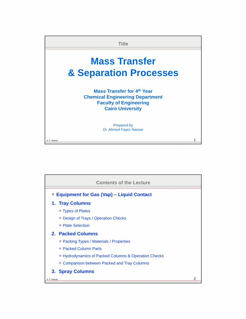
Cross Flow Plate
In a cross-flow plate the liquid flows across the plate and the vapor up through the plate. The flowing liquid is transferred from plate to plate through vertical channels called "downcomers". A pool of liquid is retained on the plate by an outlet weir.
6A. F. Nassar
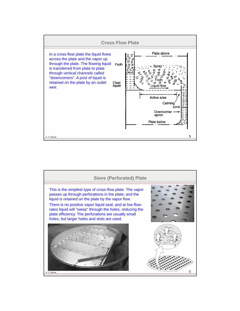
Sieve (Perforated) Plate
This is the simplest type of cross-flow plate. The vapor passes up through perforations in the plate; and the liquid is retained on the plate by the vapor flow.
There is no positive vapor liquid seal, and at low flow-rates liquid will "weep" through the holes, reducing the plate efficiency. The perforations are usually small holes, but larger holes and slots are used.
7A. F. Nassar
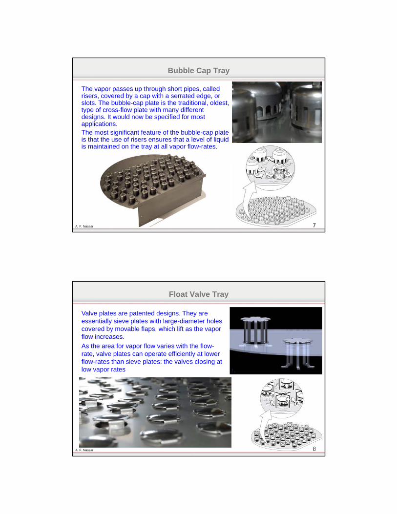
Bubble Cap Tray
The vapor passes up through short pipes, called risers, covered by a cap with a serrated edge, or slots. The bubble-cap plate is the traditional, oldest, type of cross-flow plate with many different designs. It would now be specified for most applications.The most significant feature of the bubble-cap plate is that the use of risers ensures that a level of liquid is maintained on the tray at all vapor flow-rates.
8A. F. Nassar
Float Valve Tray
Valve plates are patented designs. They are essentially sieve plates with large-diameter holes covered by movable flaps, which lift as the vapor flow increases.
As the area for vapor flow varies with the flow-rate, valve plates can operate efficiently at lower flow-rates than sieve plates: the valves closing at low vapor rates
9A. F. Nassar
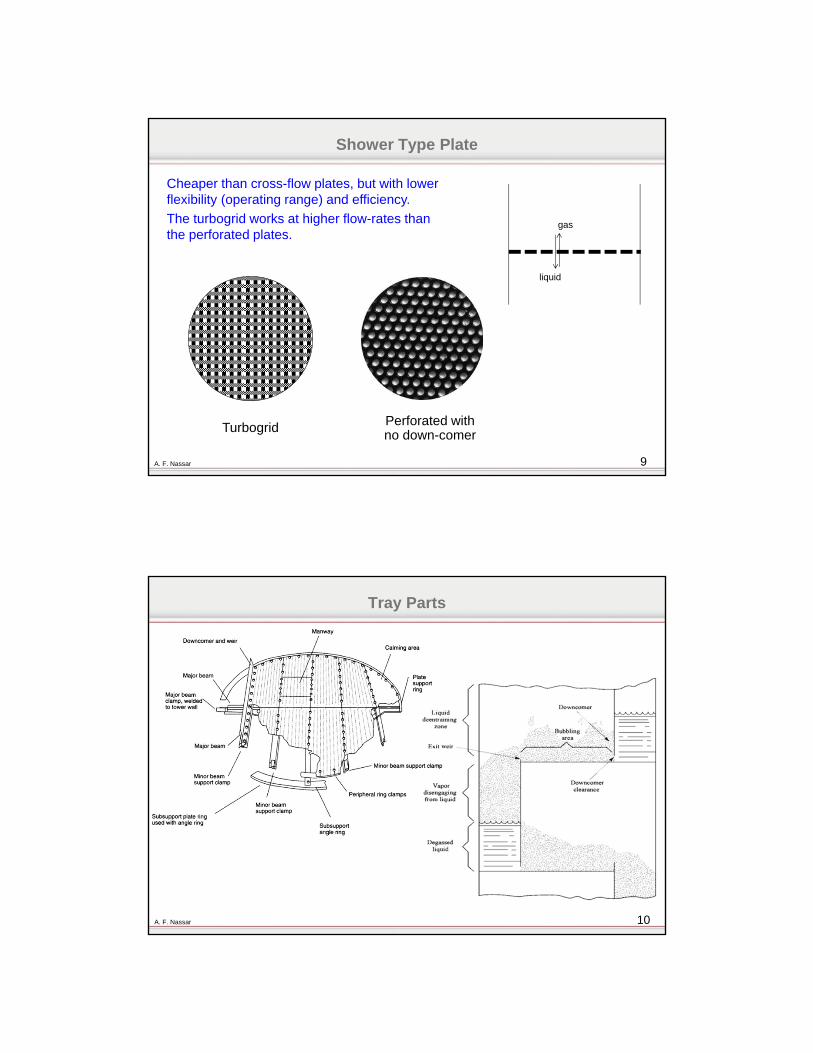
Shower Type Plate
Cheaper than cross-flow plates, but with lower flexibility (operating range) and efficiency.
The turbogrid works at higher flow-rates than the perforated plates.
Turbogrid Perforated with no down-comer
gas
liquid
10A. F. Nassar
Tray Parts
11A. F. Nassar
Design of Plates
The basic requirements of a plate contacting stage are that it should:• Provide good vapor-liquid contact• Provide sufficient liquid hold-up for good mass transfer (high efficiency)• Have sufficient area and spacing to keep the entrainment and pressure drop
within acceptable limits• Have sufficient downcomer area for the liquid to flow freely from plate to plate
12A. F. Nassar
Design of Plates
Procedure1. Calculate the maximum and minimum vapor and liquid flow-rates, for the turn down ratio
required.2. Collect, or estimate, the system physical properties.3. Select a trial plate spacing.4. Estimate the column diameter, based on flooding considerations.5. Decide the liquid flow arrangement.6. Make a trial plate layout: downcomer area, active area, hole area, hole size, weir height.7. Check the weeping rate, if unsatisfactory return to step 6.8. Check the plate pressure drop, if too high return to step 6.9. Check downcomer back-up, if too high return to step 6 or 3.10. Decide plate layout details: calming zones, unperforated areas. Check hole pitch, if
unsatisfactory return to step 6 .11. Recalculate the percentage flooding based on chosen column diameter.12. Check entrainment, if too high return to step 4.13. Optimize design: repeat steps 3 to 12 to find smallest diameter and plate spacing
acceptable (lowest cost).14. Finalize design: draw up the plate specification and sketch the layout.
13A. F. Nassar
Design of Plates
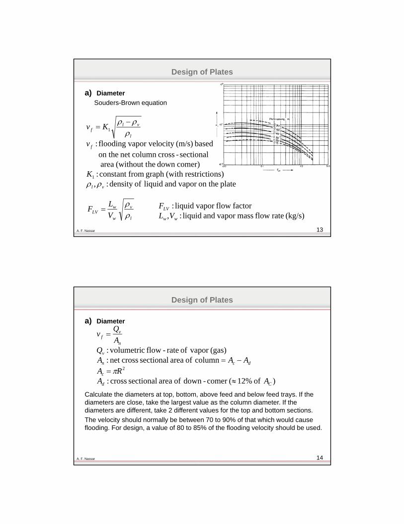
a) Diameter
Souders-Brown equation
plate on the vapor and liquid ofdensity :,ns)restrictio(with graph fromconstant :
comer)down he(without t area sectional-crosscolumn net on the
based (m/s)ocity vapor velflooding :
1
1
vl
f
l
vlf
K
v
Kv
l
v
w
wLV V
LF
(kg/s) rate flow mass vapor and liquid :,
factor flow vapor liquid :
ww
LV
VLF
14A. F. Nassar
Design of Plates
) of 12%(comer -down of area sectional cross:
column of area sectional crossnet :(gas) vapor of rate-flow c volumetri:
2
Cd
c
dcn
v
n
vf
AARA
AAAQ
A
Qv
a) Diameter
Calculate the diameters at top, bottom, above feed and below feed trays. If the diameters are close, take the largest value as the column diameter. If the diameters are different, take 2 different values for the top and bottom sections.
The velocity should normally be between 70 to 90% of that which would cause flooding. For design, a value of 80 to 85% of the flooding velocity should be used.

15A. F. Nassar
Design of Plates
b) Tray Spacing
Usually it is between 30 and 90 cm, most used between 50 and 60 cm.
Tray spacing should be smaller for low flow rates and vice versa.
c) Hole active area
Standard hole active area ratio is greater than 10%; for other ratios apply the following corrections for K1:
hole: active area multiply K1 by
10% or greater 1
8% 0.9
6% 0.8
16A. F. Nassar
Design of Plates
d) Liquid-flow arrangement
The choice of plate type (reverse, single pass or multiple pass) will depend on the liquid flow-rate and column diameter. An initial selection can be made using this figure.
17A. F. Nassar
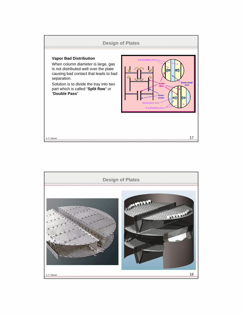
Vapor Bad Distribution
When column diameter is large, gas is not distributed well over the plate causing bad contact that leads to bad separation.
Solution is to divide the tray into two part which is called “Split flow” or “Double Pass”
Design of Plates
18A. F. Nassar
Design of Plates
19A. F. Nassar
Small Liquid flow (height on plate)
In case of small liquid height on plate, any change in that height may lead to push the liquid back and gas jets through the holes. It is also called “Coning”.
In this case increase the weir height or use “reverse flow”
Design of Plates
20A. F. Nassar
Design of Plates
e) Weir height (hw)
Weir height should be less than 15% of the plate spacing.
The higher the weir, the higher is the efficiency, but the larger is the pressure drop.
For vacuum towers use short weirs (6-12 mm).
For medium and high pressure column, pressure drop is not of any significance (use weir height of 40 – 90 mm).
f) Hole size and pitch (dh)
The hole sizes used vary from 2.5 to 12 mm; 5 mm is the preferred size. Larger holes are occasionally used for fouling systems.
The hole pitch should not be less than 2.0 hole diameters, and the normal range will be 2.5 to 4.0 diameters. Square and triangular patterns are used.
21A. F. Nassar
Design of Plates
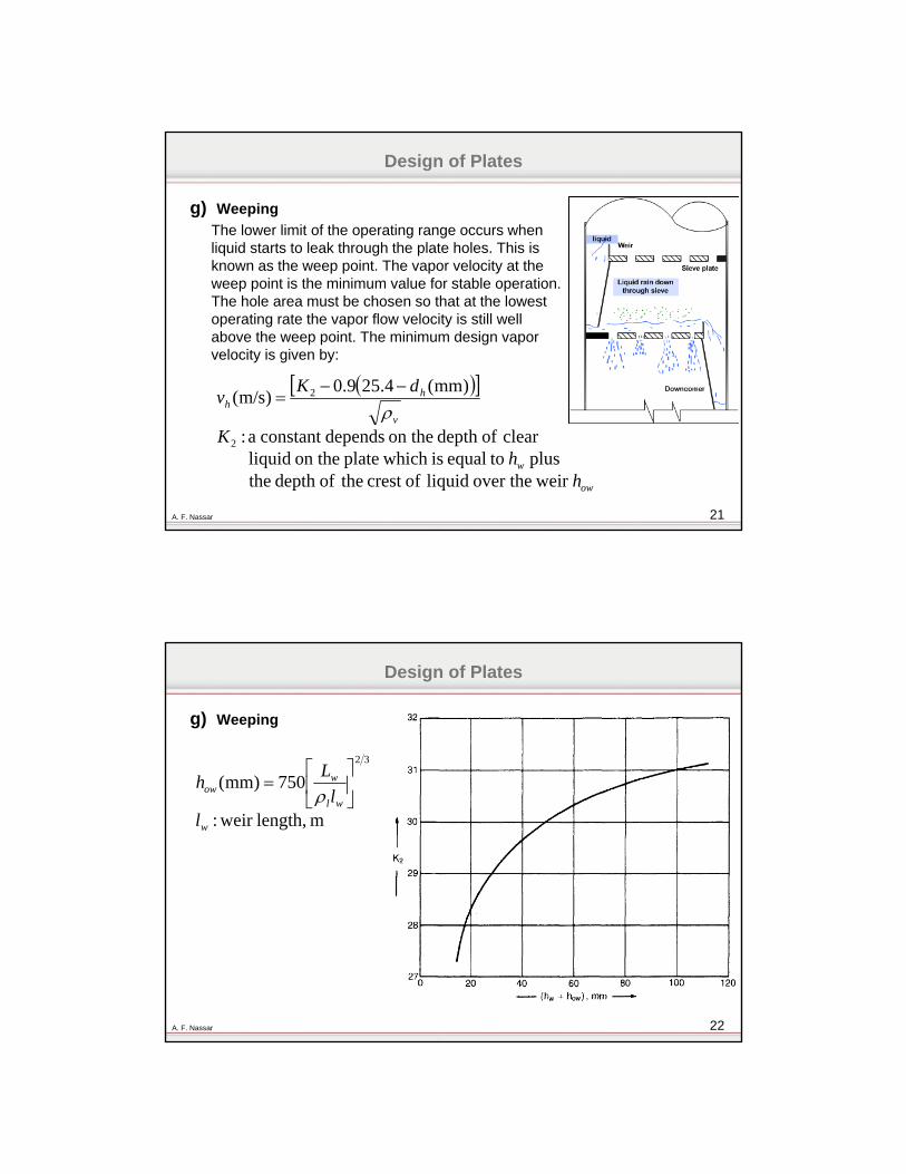
g) Weeping
The lower limit of the operating range occurs when liquid starts to leak through the plate holes. This is known as the weep point. The vapor velocity at the weep point is the minimum value for stable operation. The hole area must be chosen so that at the lowest operating rate the vapor flow velocity is still well above the weep point. The minimum design vapor velocity is given by:
ow
w
v
hh
hh
K
dKv
weir over the liquid ofcrest theofdepth theplus toequal is which plate on the liquid
clear ofdepth on the dependsconstant a :
)mm(4.259.0)m/s(
2
2
22A. F. Nassar
Design of Plates
g) Weeping
m length, weir :
750)mm(32
w
wl
wow
ll
Lh
23A. F. Nassar
Design of Plates
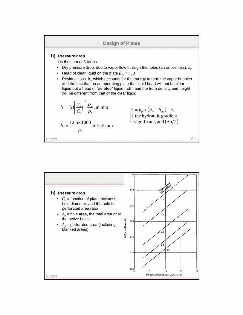
h) Pressure drop
It is the sum of 3 terms:
• Dry pressure drop, due to vapor flow through the holes (an orifice loss), hd
• Head of clear liquid on the plate (hw + how)
• Residual loss, hr, which accounts for the energy to form the vapor bubbles and the fact that on an operating plate the liquid head will not be clear liquid but a head of "aerated" liquid froth, and the froth density and height will be different from that of the clear liquid
mmin ,512
l
v
o
hd C
vh
mm 5.1210005.12
l
rh
2h add t,significan isgradient hydraulic theif
rowwdt hhhhh
24A. F. Nassar
h) Pressure drop
• Co = function of plate thickness, hole diameter, and the hole to perforated area ratio
• Ah = hole area, the total area of all the active holes
• Ap = perforated area (including blanked areas)
25A. F. Nassar
Design of Plates
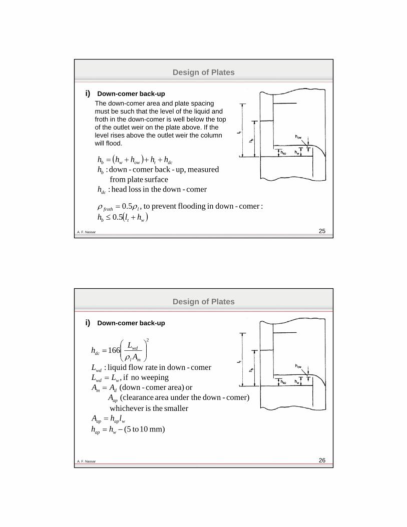
i) Down-comer back-up
The down-comer area and plate spacing must be such that the level of the liquid and froth in the down-comer is well below the top of the outlet weir on the plate above. If the level rises above the outlet weir the column will flood.
comer-down in the loss head :surface plate from
measured up,-backcomer -down :
dc
b
dctowwb
h
hhhhhh
wtb
lfroth
hlh 5.0
:comer-downin floodingprevent to,5.0
26A. F. Nassar
Design of Plates
i) Down-comer back-up
mm) 10 to(5
smaller theishichever wcomer)-down under the area (clearance
or area)comer -(down weepingno if ,
comer-downin rate flow liquid:
1662
wap
wapap
ap
dm
wwd
wd
ml
wddc
hhlhA
AAALL
LA
Lh
27A. F. Nassar
Design of Plates
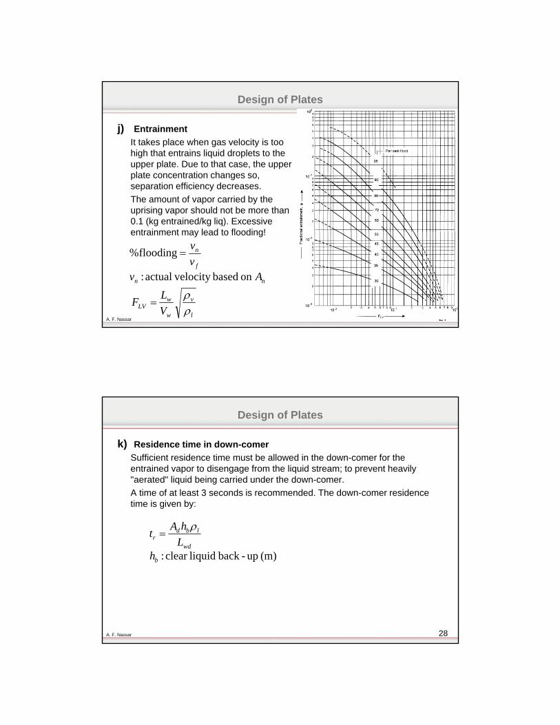
j) Entrainment
It takes place when gas velocity is too high that entrains liquid droplets to the upper plate. Due to that case, the upper plate concentration changes so, separation efficiency decreases.
The amount of vapor carried by the uprising vapor should not be more than 0.1 (kg entrained/kg liq). Excessive entrainment may lead to flooding!
nn
f
n
Avv
v
on based velocity actual :
flooding%
l
v
w
wLV V
LF
28A. F. Nassar
Design of Plates
k) Residence time in down-comer
Sufficient residence time must be allowed in the down-comer for the entrained vapor to disengage from the liquid stream; to prevent heavily "aerated" liquid being carried under the down-comer.
A time of at least 3 seconds is recommended. The down-comer residence time is given by:
(m) up-back liquidclear :b
wd
lbdr
hL
hAt

29A. F. Nassar
Safe Operation Range
30A. F. Nassar
Comparison Between Cross-Flow Trays
Bubble cap trayValve traySieve tray
High (3)Medium (1.5-2.5)Low (1)Cost
Nearly the sameEfficiency
High (40-160%)High (40-180%)Low (60-120%)Operating range
HighMediumLowPressure drop
Nearly the same (sieve then valve then bubble-cap)Capacity(flow rates)
DifficultDifficultEasyErection & Maintenance
MediumWorstBest Dirty Service
31A. F. Nassar
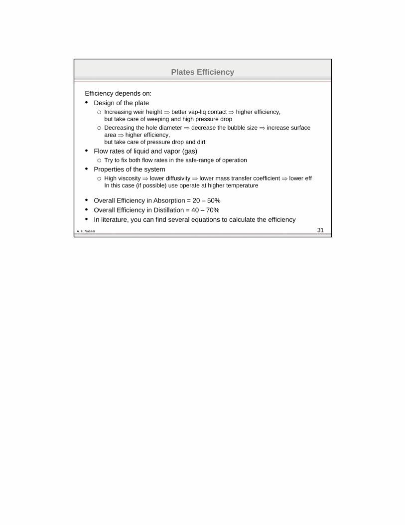
Plates Efficiency
Efficiency depends on:
• Design of the plateo Increasing weir height better vap-liq contact higher efficiency,
but take care of weeping and high pressure drop
o Decreasing the hole diameter decrease the bubble size increase surface area higher efficiency,but take care of pressure drop and dirt
• Flow rates of liquid and vapor (gas)o Try to fix both flow rates in the safe-range of operation
• Properties of the systemo High viscosity lower diffusivity lower mass transfer coefficient lower eff
In this case (if possible) use operate at higher temperature
• Overall Efficiency in Absorption = 20 – 50%
• Overall Efficiency in Distillation = 40 – 70%
• In literature, you can find several equations to calculate the efficiency