separation and concentration technologies in food processing
TRANSCRIPT

3 Separation and ConcentrationTechnologies in FoodProcessingYves Pouliot, Valérie Conway, and Pierre-Louis LeclercDepartment of Food Science and Nutrition, Université Laval, Québec, Canada
3.1 Introduction
Separation and concentration technologies are amongthe most important unit operations in food processing.From disk-bowl centrifugation for industrial-scaleproduction of skim milk to crystallization for sucroseor ultrafiltration to recover soluble proteins from cheesewhey, separation and concentration processes haveimproved food processing. These technologies haveallowed the development of new food products andare being increasingly used for water recycling in foodprocessing. Indeed, food processing consumes largevolumes of water. For this reason, waste water treatmentsuse membrane technologies as part of the solution tonumerous environmental problems posed by the foodindustries.The first processes developed to separate food compo-
nents selected physical or mechanical means that allowedsimple separations involving solid–solid or solid–liquidsystems. Screening processes separated solid-solid mate-rials into different sizes, while filtration strictly involvedthe separation of solid–liquid systems. Among screeningmethods, the pneumatic separator used compressedgases to separate particles according to their masses;the vibration separator relied on vibration to moveparticles through different screens separating solids bytheir sizes or masses; and the magnetic separator appliedmagnetic fields to remove metallic particles. As for thefiltration method, it included conventional filtration,mechanical expression (i.e. for juice extraction fromfruits or vegetables), centrifugation, and membranetechnologies.
Another group of separation and concentration tech-nologies relied on heat-induced phase changes as the driv-ing force for the separation. From simple evaporationto distillation and solvent extraction, such approachesallowed for the concentration of many liquid foods (i.e.milk, fruit and vegetable juices, etc.) and for as the indus-trial production of ethanol, liquor, and vegetable oils. Themost recent development involving phase change is theuse of supercritical carbon dioxide (CO2), which hasfound many value-added applications for the food indus-try over the past decade.Conventional filtration relies on gravity, pressure or
vacuum to create the driving force necessary for the liquidphase to pass throughout different kinds of filters (e.g. per-forated plates, cellulose filter papers, glass fiber filters) orgranularmaterial (e.g. sand or anthracite). Membranetechnologies, including reverse osmosis (RO), nanofiltra-tion (NF), ultrafiltration (UF), and microfiltration (MF),use pressure differences as the driving force of separation.Like conventional filtration, membrane filtration relies onfilters but with much smaller pores. It thus covers a widerange of separations from the removal of particles >1 μm(MF) to water purification by the removal of solutes<10−1 nm (RO) (Cui et al., 2010). In addition, recent devel-opments in electricallydriven separations (electrodialysis),low-pressure separation (pervaporation), and separationsusing functionalizedmembranes (ion exchangematerials)are opening new horizons in this fascinating field.Future trends in separation and concentration technolo-gies will be characterized by an increased number of inte-grated combinations, or hybrid processes, combiningsingle units of the before mentioned array of technologies
Food Processing: Principles and Applications, Second Edition. Edited by Stephanie Clark, Stephanie Jung, and Buddhi Lamsal.© 2014 John Wiley & Sons, Ltd. Published 2014 by John Wiley & Sons, Ltd.
33

in order to improve energy efficiency andprovide environ-mentally sustainable processes (Muralihara, 2010).Several challenges must be met in the design of efficient
and economical separation and concentration technolo-gies for the food industry.• The diversity and complexity of food systems: eachfood system has its own physical characteristics whetherit is a liquid (viscosity), a suspension (size, shape, concen-tration of particles) or a solid (mechanical and/or texturalproperties).• The lability of food components during processingconditions: many food components are prone to chemi-cal changes when exposed to high temperatures, intenseshear stress or the presence of oxygen.• The need for safe technologies: the goal of any foodprocessing method is to provide the consumer with nutri-tious and safe foods, that is, microbiologically clean andfree from external contaminants.• The need for low-energy, sustainable processes: theuncertain future of fossil energy, the rising concerns aboutgreenhouse gases and their effects on the population callfor new processes that will minimize energy consumptionand carbon footprint.The objectives of this chapter are to provide an overviewof separation and concentration technologies used in thefood industry and a better understanding of their under-lying principles, associated advantages, and limitations.This chapter also introduces new emerging technologieshaving potential use for the food industry.
3.2 Physical separation of foodcomponents
Physical separation methods are generally suitable forremoving suspended solids from slurries or for separatingsolid particles of mixtures.
3.2.1 Filtration
Solid–liquid separations can be performed using twoapproaches: (1) sedimentation, most often by means ofgravity, and (2) filtration. In the food industry, sedimen-tation is used mainly for waste water treatment and willnot be covered in this chapter.Filtration involves the removal of insoluble particles
from a suspension by passing it across a porous material,retaining particles according to their sizes – and shape tosome extent. As the filter media retain the larger particlesand form a “filter cake”, the permeate passes through the
filter barrier. The mean size particles and their distribu-tion will both have a great influence on the type of filterused. Furthermore, the technique chosen will depend onwhether the solid or the liquid is of interest to the man-ufacturer. Both efficiency and cost-effectiveness shouldbe considered in the type of filter chosen. As shown inTable 3.1, pressure, vacuum or centrifugal forces(discussed in section 3.2.2) can all be used as the drivingforces for filtration, which can be achieved using mem-brane filters, disk filters, cartridges, woven wire screensor packed bedsmade fromorganic and inorganicmaterials(i.e. minerals, carbon, glass, metal, and ceramics)(Sutherland, 2008). Filtration aids, such as diatomaceousearth, cellulose or charcoal, are often used as absorbentsto control the formation and the properties of the filtercake, in order to prevent resistance to fluid flow.Filtration equipments are mainly used in edible oil
refining, sugar refining, beer production, wine making,and fruit juice processing. The uses of MF and UF (seesection 3.4) for those latter applications are increasing,as more efficient industrial equipment and membranesbecome available. However, compared to conventional
Table 3.1 Summary of the types of filtration equipment
used in food processing
Equipmenttype
Drivingforce Advantages // Limitations
Plate-and-framefilterpress
Horizontalplatefilters
Shell-and-leaf filters
Edge filters
Pressure Large filtration area,operating at high pressures(up to 25 bar), filter cakeeasy to remove, high-quality filtration, lowcapital cost // Batch modeonly, automation difficult
Rotarydrumfilter
Rotaryvacuumdiskfilters
Pressure orvacuum
Continuous filtration, lowmanpower requirement //Lower filtration area andhigher capital cost(especially for drumfilters)
Centrifugalfilters
Centrifugal Suitable for batch orcontinuous mode //Complex handling, filtercake (sludge) difficult toremove
Reproduced from Sutherland (2008), with permission from Elsevier.
34 Food Processing: Principles and Applications

filtration, MF and UF membranes are less inclined to clogand offer greater mechanical strength (e.g. against pres-sure) and chemical resistance. Furthermore, membraneprocesses are cleaner, since they avoid the use of filteringaids such as diatomaceous earth (Daufin et al., 2001).
3.2.2 Centrifugation (separators,clarifiers)
Acentrifuge is adevice that separatesparticles fromsuspen-sions, or even macromolecules from solutions, accordingto their size, shape, and density. This method subjectsdispersed systems to artificially induced gravitationalfields (i.e. centrifugal force) as shown in Figure 3.1.Centrifugation can also be used for the separations ofimmiscible liquids. Industrial centrifugation can be dividedinto two different classes: (1) sedimenting and (2) filtering.The sedimenting type of centrifuge relies on density
(i.e. specific gravity) differences as a driving force to sepa-rate the components of a mixture. Indeed, the rotation of
materials around a fixed axis generates a centrifugal forceas much as 10,000 times greater than gravity, which actsdifferently on components depending on their specificgravity. Because denser particles require a greater forceto stay close to the rotation axis than lighter particles,the denser constituents are forced to the periphery ofthe centrifuge bowl. This type of centrifuge is suitablefor the separation of solid–liquid and liquid–liquidmixtures with very small gravity differences, as low as100 kg/m3 (Sinnott, 2005).Filtration centrifuge, in contrast to sedimentation
centrifuge, uses perforated bowls and is restricted to theseparation of solid–liquid mixtures. This type of centrif-ugal separation allows the liquid phase to permeatethrough the porous wall on which solids are retained.Unlike the sedimenting centrifuge, the filtering type ofcentrifuge has the advantage of allowing the separationof soluble solids without relying on density differences.Although particles must be at least greater than10 microns for filtration to be practicable (Leung, 2007).Centrifugation can thus provide solid–liquid and
liquid–liquid separations, such as in milk processing, inwhich milk fat (i.e. cream) removal and clarification canoccur simultaneously. Centrifugal clarification is also usedto treat oils, juices, and beers. Industrial centrifugationequipment used in food processing plants is mainly ofthe disk-bowl type, as illustrated in Figure 3.2. In recentyears, high-speed centrifugation has been used to reducebacterial counts in raw milk (i.e. so-called bactofugation)and thus, allow for the production of extended-shelf life(ESL) milk.
3.2.3 Pneumatic separation
In the food industry, air is often used to remove foreignparticles (e.g. straw, hull, and chaff ) or for classificationpurposes. Pneumatic separation is one of the oldest sepa-ration methods known to humankind. This techniqueallows the standardization of heterogeneous particlemixtures into uniform fractions based on their densityandmass. For example, in the grain industry, by using air-flows, grain or flours mixtures can be separated accordingto their size or chemical composition (e.g. protein content)(Vose, 1978). In oil extraction processes, hulls, because oftheir low density compared to seeds, can be removed usingadjusted-force airflows (Kazmi, 2012). Indeed, smallparticles fall more slowly, have less inertia and can changedirectionmore easily than larger particles. In principle, thesmaller particles (e.g. foreign particles) are dragged alongwith the air stream while larger elements fall through it.The quality of the separation depends on the behaviour
Miscible liquids X and Y
(a)
(b)
Liquid X
Liquid Y
Figure 3.1 Schematic representation of a mixture of twomiscible liquids containing particles: (a) in the absence or(b) in the presence of centrifugal force.
3 Separation and Concentration Technologies in Food Processing 35

of particles in the air stream. Indeed, each material mustpossess different aerodynamic properties to be accuratelyseparated. For example, the efficiency of pneumatic sepa-ration in flour classification, which refers to the recoveryof the desired product from the raw material at a givencut-off point, varies from 50% to 80% (Vose, 1978).
3.2.4 Mechanical expression
The extraction of oil or juice from plant materials presentsan additional challenge since it requires the disruption ofcell structures and hull-protected seeds of varying thick-ness and resistance. The methods generally used for oilrecovery are expression and solvent extraction or the com-bination of both. Expression is the oldest method appliedfor oilseeds extraction. The principle of expression issimple. First, the preconditioned oilseeds are pressed ina permeable barrel-like cavity where shear forces, com-bined or not with heat, squeeze the oil out from the seeds.
Second, the “cake” products, or de-oil material, exit fromone side of the press as oil flows throughout the barrel’sopenings and is collected (Kazmi, 2012).Mechanical and thermal pretreatments of seed are both
essential to enhance oil extraction process performances.Those treatments generally involve dehulling, flaking orgrinding of seed, cooking and sometimes enzymatic pre-treatment (Kazmi, 2012; Savoire et al., 2013). As dehullingand reduction size steps ensure homogeneous materialand increase the surface area, cooking helps break downoil cells, lowers oil viscosity, adjusts moisture, coagulatesproteins, and inactivated enzymes (Kazmi, 2012; Khan &Hanna, 1983). The cooking step is usually done using hotsteam. However, it can also use dielectric heat generation(i.e. microwave and radiofrequency) or non-thermalprocesses such as electric pulsed fields (Kazmi, 2012).Two kinds of presses can be employed for pressing
purposes: the screw press and the hydraulic press.Screw presses have the advantage of giving a higher yield
Locking nut
(a)
Bowl top
Partition(withcream screw)
Plates
‘O’ ring
Bowl base
(b)
Cream
Who
le m
ilk Separated milk
Channel forascending liquid
Bowl lid
Separatingdisk
Diskstack
Disk holderwith feedinlet
Bowl base
Separation force
Figure 3.2 Disk-bowl centrifuge: (a) separator components, (b) separation of cream from milk.
36 Food Processing: Principles and Applications

and are suitable for a continuous mode. For this reason,hydraulic presses are only used for specialty oil, olive oil,and for the pressing of cocoa (Savoire et al., 2013). The dif-ferent operating zones of a common screw press are illus-trated in Figure 3.3.Efficiency of mechanical oil extraction is low compared
to solvent extraction. Indeed, depending on the type of seedand the operation parameters (i.e. temperature, pressure,time, and seed moisture content), maximum attainableyield is limited to around 80% (Hasenhuettl, 2005).Moreover, if a yield of 70−80% is generally obtainablefor high-fat oilseeds (e.g. sunflowers, sesame, linseed, rape-seed, palm kernel, etc.), the yield drops to roughly 50−70%for seeds containing less than 20% of oil (e.g. soybeans)(Bargale, 1997). However, this process has the advantageof giving high-quality oils, free from dissolved chemical,and is a safer process than solvent extraction (Fellows,2009). For this reason, expression is generally limited toa small-capacity plant, to high-fat oilseeds (>35%) or tospecialty products (e.g. natural or organic oils, essential oils,etc.) (Lin & Koseoglu, 2005; Rosenthal et al., 1996).
In fruit processing, presses can remove most of thejuices from the pulp with minimal undesired components(i.e. phenolic compounds which cause bitterness andbrowning). Using continuous mode, yield of around84% of juice is obtainable. The efficiency of juice extrac-tion by mechanical expression depends on the maturity ofthe rawmaterial, the physical resistance of the structure tomechanical deformation, the time, the pressure, the juiceviscosity, as well as the temperature (Fellows, 2009).
3.3 Processes involving phase separation
3.3.1 Liquid-liquid
3.3.1.1 Crystallization
Crystallization is the process by which solid crystals, ofa solute, are formed from a solution (Berk, 2009a). Inthe food industry, products such as sugar, lactose, glucose,and salt are obtained by this process. It may also be used
Feeding
zone
Seeds are
transported
by the screw
and air
begins to be
expulsed
Seeds
crushing
occured and
air contained
in and
between the
seeds is
expulsed
Seeds
mass is
compressed
and oil is
exuded
Pressure
release
provokes
water
vaporization
responsible
for meal
expansion
Transport
zone
Compression
zone
Exudation
zone
Expansion
zone
Figure 3.3 Schematic representations of the operating zones of a typical screw press (Savoire et al., 2013).
3 Separation and Concentration Technologies in Food Processing 37

to remove undesirable products. For example, edibleoils may be cooled to crystallize high melting-pointcomponents by a process called winterizing.Crystallization generally involves four distinctive steps:
(1) the generation of a supersaturated state, (2) nuclea-tion, (3) crystal growth, and (4) recrystallization(Hartel, 2001). A supersaturated solution is generatedwhen a solution has reached the solute’s maximum con-centration and is then further concentrated, usually byevaporation, or cooled down slowly (Hartel, 2001). Thisfirst step is the driving force for crystallization by whichthe system lowers its energy state. Then nucleation takesplace as solutes aggregate to form orderly “clusters” ornuclei. There are two kinds of nucleation: (1) homogene-ous and (2) heterogeneous. The first occurs without thepresence of foreign particles and the second, more com-mon, is aided by the presence of foreign particles in thesolution. The subsequent binding of solute molecules toexisting nuclei, thus increasing crystal size, is called crystalgrowth. This reaction stops as an equilibrium state isreached, if the solution is not kept in a supersaturatedstate by the constant removal of solvent, usually throughconstant solvent evaporation (Berk, 2009a). Finally, therecrystallization step naturally takes place by the reorgan-ization of the crystalline structure to a low-energy state.The supersaturation (β), the rate of homogeneous nucle-ation (J), and the rate of crystal growth (G), are given bythe following equations (Berk, 2009a):
β =ccs
ð3:1Þ
J = aexp −16π3×
V2σ3
kTð Þ3 Inβð Þ2" #
ð3:2Þ
G= k0 C−Csð Þg ð3:3Þ
a = a constantC = concentration (kg solute per kg solvent)Cs = saturation concentration (kg solute per kg solvent)g = a numerical called growth orderk = the Boltzmann constantk0 = empirical coefficientT = temperature, KV =molar volume of the solutes = nucleus-solution surface tensionb = supersaturation ratioThe equipment used for crystallisation is called acrystallizer or pan. Pans can crystallize in batch or contin-uous mode. They can be equipped with a vacuum or be
vented, and generally include a heat exchanger as wellas an agitation device.In the food industry, crystallization is mainly used for
sugar refining,most commonly to obtain sucrose.Toobtainsucrose, sugar must be removed from sugar canes or sugarbeets to produce a diluted liquid which is then clarified toremove impurities (i.e.mineralsandorganicmatters)beforefurther concentration, commonly by evaporation. Thesucrose syrupobtained is thensubjected toacontrolledcrys-tallization process using a vacuumevaporator pan, allowingfor the sucrose to separate. Since sucrose solubility in wateris high, multiple steps are necessary to remove as much ofthe sucrose in the solution as possible. Last, sucrose crystalsare removed from the mother liquor using centrifugation.This liquor contains a low amount of sucrose and a highconcentration of impurities and is further evaporated toobtain molasses (Hartel, 2001).
3.3.1.2 Distillation
Distillation is a physical process whereby volatile compo-nents of a mixture are separated based on differencesin their volatility – the compounds with the lowestboiling point and the highest vapor pressure are separatedfirst. The equilibrium relationships for two-componentvapor–liquid mixtures are governed by the relative vaporpressure of its constituents and can conveniently bepresented in a boiling temperature-concentration dia-gram (Figure 3.4). Indeed, the partial valor of a compo-nent (PA) is proportional to its mole fraction (XA) at aspecific temperature and the total vapor pressure of amixture is the sum of the partial pressure of its compo-nents (PA + PB) (Fellows, 2009). This equilibrium rela-tionship can also be expressed mathematically as follows:
PA =XA × PA∘ ð3:4Þ
PB =XB × PB∘ ð3:5Þ
Total vapor pressure =PA + PB ð3:6Þ
A = component AB = component BP = partial pressure, kPaP� = partial pressure of the pure component, kPaX = component fraction,moleof (AorB)/mole total (A + B)The horizontal line in the boiling temperature-concentration diagram (see Figure 3.4) gives the compo-sition of a boiling liquid (x) and of the vapor (y) at a
38 Food Processing: Principles and Applications

specific temperature. The diagram shows that, at a giventemperature, the vapor (y) is richer in the more volatilecomponent than the boiling liquid (x) and this is the basisfor separation by distillation.For example, in an ethanol–water mixture, as the
linkages between similar molecules are greater thanbetween dissimilar ones, following heating, the weakerethanol–water linkages break down more easily as themore volatile compound (i.e. ethanol) is vaporized.Thereby, after condensation of the vapor, the distillate willbe concentrated in stronger ethanol–ethanol linkages andfurther concentration by vaporization will be harder.In fact, some mixtures, like ethanol–water, form azeo-tropes in which equilibrium prevents further distillation.Indeed, at 95.6% of ethanol (w/w) and 4.4% of water, themixture boils at 78.15 �C, being more volatile than pureethanol (i.e. boiling point of 78.5 �C). For this reason,ethanol cannot be completely purified by direct fractionaldistillation (Fellows, 2009).The typical distillation equipment used for continuous
fractionation of liquids consists of three main items: (1) aboiler, which generates the necessary heat to vaporize theinitialmixture; (2) a column, inwhich the stages for the dis-tillation separation are provided; and (3) a condenser, forcondensation of the final product (i.e. distillate) into theupper column. The distillation column contains multiple
contact stages, throughwhich liquidmovesdownandvapormoves up (Figure 3.5b). This method allows the vapor trav-eling up the column to be cooled by the descending liquidand the liquid to be heated by the ascending vapor. The liq-uid can thus lose its more volatile components as it travelsdown the column and the vapor can be enriched as itmovesup.Apart of liquid obtained by condensation of the vapor isfed back (i.e. the reflux) into the upper part of column (i.e.the rectification zone) in order to provide sufficient liquidfor contact with the gas (Berk, 2009b).Even if most industrial distillation operations use
continuous distillation columns, distillation in batchmodeis still used in the production of spirits such aswhiskey andcognac (see Figure 3.5a). In the food industry, despite itssimplicity and low capital cost, distillation is mainly con-fined to the concentration of alcohol beverages, essentialoils, volatile flavors, aroma compounds, and to thedeodorization of fats and oils. Along with evaporation,distillation is one of themost energy-consuming processesused in the food industry (Fellows, 2009).
3.3.1.3 Solvent extraction
Solvent extraction is the separationof a soluble compound,the solute, by diffusion from a solid (e.g. plant material) orliquid (e.g. oil)matrix using a volatile solvent. For example,
Vapor composition
line
Liquid composition line
Boiling temperature
of pure A
0 B
1•0 A
0•5 B
0•5 A
1•0 B
0 A
“y” “x”
Tem
pera
ture
Boiling temperature
of pure B
Composition of mixture – mol fractionFigure 3.4 Boiling temperature/concentrationdiagram.
3 Separation and Concentration Technologies in Food Processing 39

in the case of compounds extracted from solid materialssuch as plants, the solid fragments are mixed with solventand are held for a predetermined lap of time before theremoval of the solvent. This holding process involvestwo stages: (1) an initiation stage; and (2) a diffusion stage.In the initiation stage, solid fragments swell as they absorbsolvent and the soluble components are dissolved. Then,diffusion occurs within the fragments outward. The hold-ing time must be sufficient for solutes to dissolve in the
solvent (Fellows, 2009). The fraction extracted is a functionof both the distribution ratio (D) and the phase ratio(Θ) and can be expressed mathematically as follows(Rydberg et al, 2004):
Dx =Xe½ �Xa½ � ð3:7Þ
Θ=Ce
Vað3:8Þ
Ex =DxΘ� DxΘ+ 1ð Þ ð3:9Þ
Where;a = aqueous phase, e = solvent, x = desired componentDx = distribution ratioEx = fraction extractedV = volumeX = fraction of the desired componentѲ = phase ratioSolvent extraction can be performed in batch, semi-batchor continuous mode. A continuous solvent extractionprocess is presented in Figure 3.6. In this process, thematerial to be extracted is placed in an extraction vessel(i.e. extractor) into which the solvent is introduced at acertain temperature and flow rate. The solvent is thenpassed into a vessel (i.e. separator) in which the solventand the extracted compounds are separated, generally byevaporation and finally vacuum distillation. The solventvapor is then sent to a condenser to be recycled and crudeoil is submitted to a refining process (i.e. degumming, alkalirefining, bleaching, and deodorization) (Rosenthal et al.,
Condenser
Pot still
(a)
Distillate (D)
D
Condenser
Reflux
(b)
Distillate (D)
Stripping section
Bottoms (B)
Reboiler
Feed (F)
Rectifying
section
Figure 3.5 Schematic diagram of a typical distillation apparatus:(a) pot still and (b) distillation columns. Adapted fromBerk (2009b).
Extractor
S(l)
S(g)
S(l)
S(g)
M
E
Separator Condenser
Figure 3.6 Schematic representation of a solvent extractionunit (S = solvent; M =material; E = extract). Adapted fromGrandison and Lewis (1996).
40 Food Processing: Principles and Applications

1996). The requirements for batch and continuous extrac-tion mode are presented in Table 3.2.The efficiency of solvent extraction strongly depends
on the solid material condition, the diffusion rate in thesolid, the liquid-to-solid ratio, the temperature, the sol-vent selection (i.e. type, viscosity, and flow rate), thesolid’s water content, and the presence of competingextractable components (Fellows, 2009; Rydberg et al.,2004: Takeuchi et al., 2008). A pretreatment step likegrinding or flaking, prior to extraction, enhances surfacecontact between the solvent and the solid matrix and thusextraction efficacy. Also, a higher liquid-to-solid ratioprovides an increased gradient which facilitates thesolute’s diffusion. High temperatures increase the solute’ssolubility and diffusion rate and result in a higher masstransfer rate. Residual water in solid material can nega-tively affect the solvent’s capacity to dissolve solutesand thus, affect themass transfer. However, the major fac-tor influencing the efficiency of solvent extraction is thenature of the solvent used. For this reason, most extrac-tion techniques manipulate the physical properties of sol-vents in order to reduce the surface tension, increase thesolute’s solubility, and promote a higher diffusion rate(Takeuchi et al., 2008).Solvents range from polar, meaningmiscible with water
(e.g. ethanol, methanol), to non-polar, which means com-pletely immiscible with water (e.g. hexane). Thus, polarcompounds are more soluble in polar solvents whereasnon-polar compounds are more readily dissolved innon-polar ones. Selection of the solvent is therefore basedon the chemistry of the compound of interest as well as oncost and toxicity. Table 3.3 shows the dielectric constant(DC) of various solvents – a parameter related to polarityor their ability to separate chargedmolecules (Voet&Voet,2005). Non-polar solvents (e.g. hexane) have very lowDC,while polar solvents (e.g. ethanol, water) have very highDC. For example, water is used to extract sugar, coffee
and tea solutes, but oil and fat extractions require a lesspolar solvent, generally hexane.Another important factor influencing the extraction
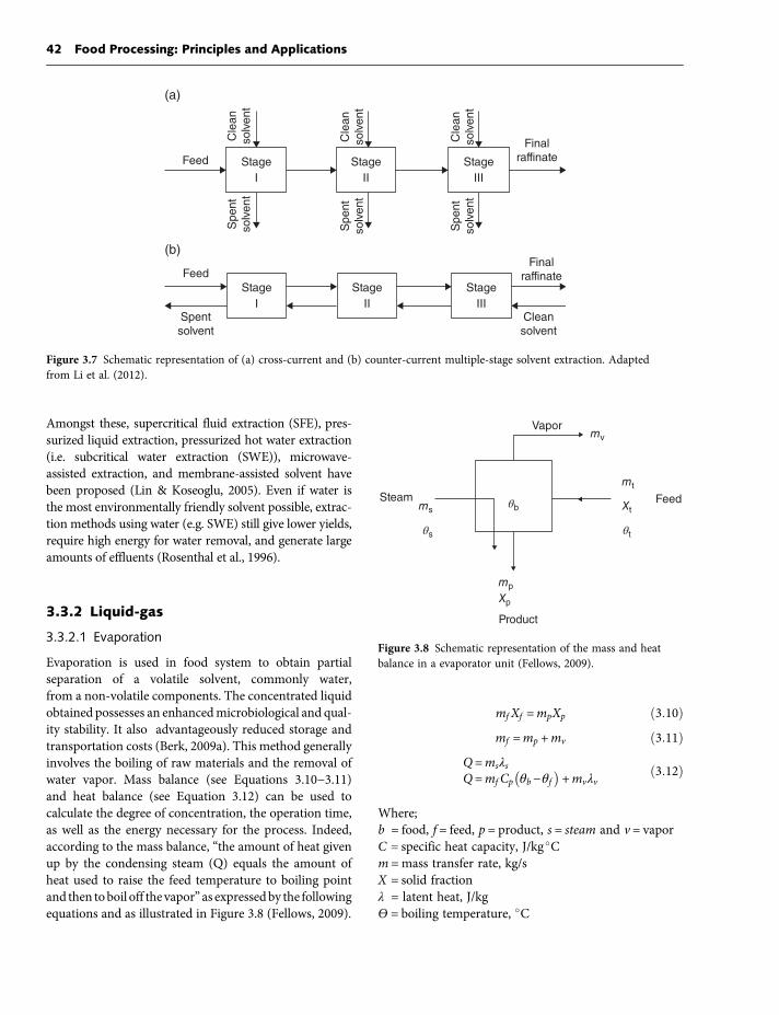
quality is the number of extraction steps or stages. Indeed,efficiency of the extraction increases along with theirnumbers. Although single stages have low operating costs,this type of extractor produces diluted solutions involvingthe use of expensive solvent recovery systems (Fellows,2009). They are rarely used commercially and arerestrained to the extraction of specialty oils or to the pro-duction of coffee and tea extracts. Multistage apparatuscan be viewed as single-stage extractors linked together,allowing the solvent emerging from an extractor’s basesto be pumped cross-currently or counter-currently tothe next one (Fellows, 2009). Multistage apparatus offerssignificant advantages such as higher recovery and purity(Rydberg et al., 2004). In the cross-current mode(Figure 3.7a), the feed, and thereafter the raffinate or res-idue, are treated in successive stages with fresh solvent.Though operation in cross-current mode offers moreflexibility, it is not very desirable due to the high solventrequirements and low extraction yields (Kumar, 2009).For larger volume operations and more efficient uses ofsolvent, a counter-currentmode is employed (Figure 3.7b).In counter-current operation, the feed enters the firststage as the final extract leaves. The last stage receivethe fresh solvent as the final raffinate leaves. Thecounter-current operation provides a higher driving forcefor solute’s mass transfer and thus, gives an optimal per-formance and is the preferred set-up (Berk, 2009c;Kumar, 2009).Despite its widespread use in food processing, solvent
extraction has considerable drawbacks related to solventcosts, toxicity and reactivity. Also, potential environmentalproblems are associated with their use, storage, and dis-posal. For these latter reasons, modern environmentallysafe and cost-effective extraction techniques are emerging.
Table 3.2 Requirements for solvent extraction of oils
Requirements(per tonne ofoilseeds)
Batchprocessing
Continuousprocessing
Steam, kg 700 280Power, kW/h 45 55Water, m3 14 12Solvent, kg 5 4
Reproduced from Fellows (2009), with permission from Elsevier.
Table 3.3 Dielectric constant of solvents used for extraction
Solvent Dielectric constantType of molecules
dissolved
Hexane 1.9 OilsToluene 2.4 OilsEthanol 24.3 PolyphenolsMethanol 32.6 PolyphenolsWater 78.5 Salts, sugar
Based on Voet and Voet (2005).
3 Separation and Concentration Technologies in Food Processing 41
Amongst these, supercritical fluid extraction (SFE), pres-surized liquid extraction, pressurized hot water extraction(i.e. subcritical water extraction (SWE)), microwave-assisted extraction, and membrane-assisted solvent havebeen proposed (Lin & Koseoglu, 2005). Even if water isthe most environmentally friendly solvent possible, extrac-tion methods using water (e.g. SWE) still give lower yields,require high energy for water removal, and generate largeamounts of effluents (Rosenthal et al., 1996).
3.3.2 Liquid-gas
3.3.2.1 Evaporation
Evaporation is used in food system to obtain partialseparation of a volatile solvent, commonly water,from a non-volatile components. The concentrated liquidobtained possesses an enhancedmicrobiological and qual-ity stability. It also advantageously reduced storage andtransportation costs (Berk, 2009a). This method generallyinvolves the boiling of raw materials and the removal ofwater vapor. Mass balance (see Equations 3.10−3.11)and heat balance (see Equation 3.12) can be used tocalculate the degree of concentration, the operation time,as well as the energy necessary for the process. Indeed,according to the mass balance, “the amount of heat givenup by the condensing steam (Q) equals the amount ofheat used to raise the feed temperature to boiling pointand then toboil off the vapor” as expressedby the followingequations and as illustrated in Figure 3.8 (Fellows, 2009).
mf Xf =mpXp ð3:10Þmf =mp +mv ð3:11Þ
Q=msλsQ=mfCp θb−θf
� �+mvλv
ð3:12Þ
Where;b = food, f = feed, p = product, s = steam and v = vaporC = specific heat capacity, J/kg �Cm =mass transfer rate, kg/sX = solid fractionλ = latent heat, J/kgѲ = boiling temperature, �C
Feed
(a)
Final
raffinate
Cle
an
so
lve
nt
Sp
en
t
so
lve
nt
Sp
en
t
so
lve
nt
Sp
en
t
so
lve
nt
Cle
an
so
lve
nt
Cle
an
so
lve
nt
Stage
I
Stage
II
Stage
III
(b)Final
raffinateFeed
Spent
solvent
Clean
solvent
Stage
I
Stage
II
Stage
III
Figure 3.7 Schematic representation of (a) cross-current and (b) counter-current multiple-stage solvent extraction. Adaptedfrom Li et al. (2012).
Steam
Vapor
Feed
θs
θb
θt
ms
Product
mp
Xp
mv
mt
Xt
Figure 3.8 Schematic representation of the mass and heatbalance in a evaporator unit (Fellows, 2009).
42 Food Processing: Principles and Applications

An evaporator is essentially composed of a heat exchanger,or calandria, equipped with a device which allows forthe separation of vapors from the processed liquid. Heat,commonly from saturated steam, is transferred through acontact surface, generally stainless steel. The driving forcefor heat transfer is the temperature difference between thesteam (s) and the feed (f ). The process is completed whenwater vapor (v) yielded by the product (p) is removed as acondensed liquid. The steam generated during evaporationcan be reused to heat several other evaporators or stages, inwhat is called multieffect evaporation (Figure 3.9). Thisprocess is especially interesting since it lowers energy costsrelated to steamproductionbyusing thevapor coming fromone effect to heat the product in the next effect. However, tobe able to perform this in practice, the boiling point of thesubstance (θ) must be decreased, stage by stage, in orderto maintain the temperature difference between the steamand the feed (Barta et al., 2012; Fellows, 2009). The progres-sive reduction of pressure by the application of a vacuumstate increases the heat transfer and allows the product toboil at lower temperatures. Indeed, while evaporation withsingle-stage devices requires 1.1 kg of steam to evaporate1 kg of water, only 0.5–0.6 kg of steam is necessary usinga two-stage unit (Barta et al., 2012). The application ofvacuumevaporation not only reduces energy consumption,it also preserves quality in heat-sensitive products such asmilk. In fact, excessive heating time as well as high tempera-tures can lead to undesired chemical reactions (e.g.Maillardreactions in milk) or to the degradation of compounds(e.g. vitamins).The different types of evaporators used in the food indus-
try include batch pans and boiling film evaporators. Batchpans are the simplest and oldest types of evaporators, con-sisting essentially of a hemispherical, steam-jacketed vessel.Their heat transfer per unit volume is slower, and they thusrequire long residence times. Because their heat transfercharacteristics are poor–using only natural convection–batch pans have been largely replaced by modern film
evaporation systems. In boiling film evaporators, the prod-uct flows as a thin filmover a heated surface. Several kinds offilm evaporators are available, such as: climbing film, fallingfilm (Figure 3.10), and plate evaporators (Figure 3.11). Inclimbing film evaporators, the liquid moves rapidlyupwardsbypercolationalongvertical tubesanduponreach-ing the top, theconcentratesandvaporsproducedare sent toa separator. In the case of falling film evaporators, a thin liq-uid film of uniform thickness moves downwards by gravityinside tubes. Compared to the climbing film evaporator, theresidence time of the product is shorter, and this type ofapparatus allows a great number of effects (Singh & Held-man, 2008). The same rising and falling principles of evap-oration can be used on heat exchange surfaces as a series ofplates (i.e. plate evaporators), as shown in Figure 3.11.A good example of the use of evaporation in the food
industry is the manufacture of tomato paste. Tomato pasteoriginates from tomato juice (i.e. 5−6% of solids) in whichwater is removed by evaporation to reach 35−37% of solids(Singh & Heldman, 2008). Condensed milk and concen-trated fruit juices are other examples of food productsinvolving evaporation processes. Compared to membraneprocesses, a higher degree of concentration is attainableusing evaporation (i.e. around 85% compared to 30%),but it involves high energy costs and product quality losses(Kazmi, 2012). Compared to freeze-drying processes,evaporation requires 10–15 times more energy for waterremoval. However, certain technological problems hamperthe widespread application of freeze concentration inthe food industry. Indeed, freeze concentration involvesexpensive systems, considerable loss of solids, and lowdegreeof concentration(i.e.maximumof50−55%ofsolids).
3.3.2.2 Supercritical fluid extraction (SFE)
Supercritical fluid (SCF) is the state in which the liquidand the gas phases are indistinguishable and in whichthe compound exhibits properties of both phases.
Feed
S
1 2 nVacuum pump
Product
Figure 3.9 Schematic representation of a multiple effect co-current evaporator (Berk, 2009b).
3 Separation and Concentration Technologies in Food Processing 43
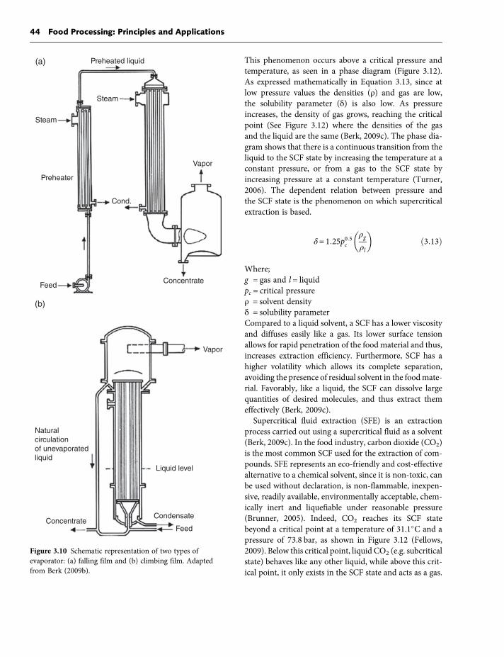
This phenomenon occurs above a critical pressure andtemperature, as seen in a phase diagram (Figure 3.12).As expressed mathematically in Equation 3.13, since atlow pressure values the densities (ρ) and gas are low,the solubility parameter (δ) is also low. As pressureincreases, the density of gas grows, reaching the criticalpoint (See Figure 3.12) where the densities of the gasand the liquid are the same (Berk, 2009c). The phase dia-gram shows that there is a continuous transition from theliquid to the SCF state by increasing the temperature at aconstant pressure, or from a gas to the SCF state byincreasing pressure at a constant temperature (Turner,2006). The dependent relation between pressure andthe SCF state is the phenomenon on which supercriticalextraction is based.
δ= 1:25p0:5cρgρl
� �ð3:13Þ
Where;g = gas and l = liquidpc = critical pressureρ = solvent densityδ = solubility parameterCompared to a liquid solvent, a SCF has a lower viscosityand diffuses easily like a gas. Its lower surface tensionallows for rapid penetration of the food material and thus,increases extraction efficiency. Furthermore, SCF has ahigher volatility which allows its complete separation,avoiding the presence of residual solvent in the foodmate-rial. Favorably, like a liquid, the SCF can dissolve largequantities of desired molecules, and thus extract themeffectively (Berk, 2009c).Supercritical fluid extraction (SFE) is an extraction
process carried out using a supercritical fluid as a solvent(Berk, 2009c). In the food industry, carbon dioxide (CO2)is the most common SCF used for the extraction of com-pounds. SFE represents an eco-friendly and cost-effectivealternative to a chemical solvent, since it is non-toxic, canbe used without declaration, is non-flammable, inexpen-sive, readily available, environmentally acceptable, chem-ically inert and liquefiable under reasonable pressure(Brunner, 2005). Indeed, CO2 reaches its SCF statebeyond a critical point at a temperature of 31.1�C and apressure of 73.8 bar, as shown in Figure 3.12 (Fellows,2009). Below this critical point, liquid CO2 (e.g. subcriticalstate) behaves like any other liquid, while above this crit-ical point, it only exists in the SCF state and acts as a gas.
Steam
Steam
Preheated liquid(a)
Preheater
Feed
Cond.
Vapor
Concentrate
(b)
Natural
circulation
of unevaporated
liquid
ConcentrateCondensate
Liquid level
Vapor
Feed
Figure 3.10 Schematic representation of two types ofevaporator: (a) falling film and (b) climbing film. Adaptedfrom Berk (2009b).
44 Food Processing: Principles and Applications

The SFE apparatus is similar to the one used for solventextraction (see section 3.3.1.3). However, the extractionand separation vessels of SFE apparatus are pressurizedchambers equipped with heat exchangers since the stateof CO2 is determined by pressure and temperature. TheCO2 is stored in a subcritical state (i.e. liquid state) insidethe condenser and pumped into the extraction vesselthroughout a heat exchanger by a high-pressure pump.In the extraction vessel, as a result of higher pressure
and temperature, CO2 reaches the SCF state before beingmixed in the food material (Fellows, 2009). Afterwards,SCF-CO2 passes into the separation vessel where the pres-sure is lowered, allowing for the return of CO2 to its gas-eous state and thus for the precipitation of the dissolvedsolutes in the separation vessel (see Figure 3.12). Finally,the extracted compounds are removed from the separa-tion vessel as the gaseous CO2 is sent to a condenser tobe recycled and stored in its subcritical state (e.g. liquidstate) by lowering the temperature.Supercritical fluid extraction can nowadays be per-
formed at an analytical, pilot scale as well as in large-scaleindustrial plants. More than 100 industrial plants andaround 500 pilot plants are using this technology world-wide (Turner, 2006). Supercritical processes can be usedto extract a wide variety of molecules such as lipids(e.g. seed oil, fish oil, specific fractions of butter fat or spe-cific essential fatty acids), caffeine from coffee beans andtea leaves (decaffeinated), alcohol from beer and wines,lecithin, bioactive compounds (i.e. antioxidants, phytos-terol, and vitamins) and various flavors, colorants, andfragrances (Sahena et al., 2009). This extraction tech-nology offers extraction yields comparable to those ofconventional solvent extractions, and can be carried outin different modes of operation (e.g. batch, single stage,multistage, usually in counter-current mode).
Vapor
Separator
Concentrate
Condensate outlet
HeadGaskets
Ste
am
spacers
Steam
Feed
Steam
section
Steam
section
Steam
section
Discharge
section
Inlet
section
Figure 3.11 Schematic representation of a plate evaporator (Berk, 2009b).
Pressure
(bar (psl))
74 (1100)
5 (78)
Solid
–57° 0° 31°
Temperature (°C)
Triple point
Critical pointSupercritical
fluidLiquid
Gas
Figure 3.12 Pressure-temperature phase diagram for CO2.Adapted from Fellows (2009).
3 Separation and Concentration Technologies in Food Processing 45
In the food industry, large-scale uses are mainly for thedecaffeination of coffee beans and black tea as well as forthe removal of bitter flavors from hops (Rizvi, 2010). Forexample, Kaffee HAG AG, originally from Bremen, Ger-many, is a worldwide brand of SFE-CO2 decaffeinatedcoffee owned by US multinational Kraft Foods (50,000ton/year of coffee) (Otles, 2008). However, extractionsof added-value components such as specific fatty acidsand essential oils are still limited to smaller scale plants(Brunner, 2005). Overall, even if SFE using CO2 is advan-tageous in terms of safety (i.e. food quality and environ-ment) and operating costs, the industrial use of thistechnology is limited due to high investment costs.
3.4 Membrane separations
3.4.1 Pressure-driven processes
3.4.1.1 Basic principles and separation ranges(RO, NF, UF, MF)
Pressure-driven membrane separation processes havebeen integrated as unit operations into a large numberof food processes and it is one of the fastest growing tech-nologies in the field of separation methods. Membranetechnology requires low capital as well as low utility costs,and for this reason membrane separation has replacedthe conventional separation technique in many food pro-cesses. In fact, conventional separation and concentrationtechniques usually imply energy-consuming phasechanges which can affect both the physical and chemicalcharacteristics of the final product. Furthermore, mem-brane systems, when compared with the conventionaltechnology of separation and concentration, only require
limited space and thus do not involve expensive installa-tions (Philipina & Syed, 2008).Membrane processes are classified based on four main
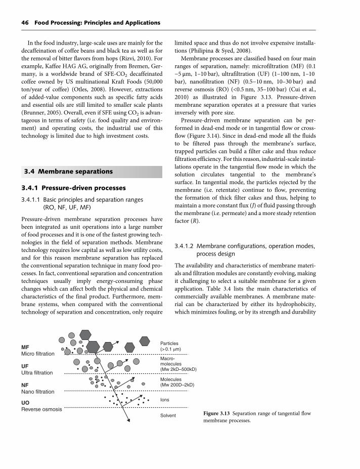
ranges of separation, namely: microfiltration (MF) (0.1−5 μm, 1–10 bar), ultrafiltration (UF) (1–100 nm, 1–10bar), nanofiltration (NF) (0.5−10 nm, 10–30 bar) andreverse osmosis (RO) (<0.5 nm, 35–100 bar) (Cui et al.,2010) as illustrated in Figure 3.13. Pressure-drivenmembrane separation operates at a pressure that variesinversely with pore size.Pressure-driven membrane separation can be per-
formed in dead-end mode or in tangential flow or cross-flow (Figure 3.14). Since in dead-end mode all the fluidsto be filtered pass through the membrane’s surface,trapped particles can build a filter cake and thus reducefiltration efficiency. For this reason, industrial-scale instal-lations operate in the tangential flow mode in which thesolution circulates tangential to the membrane’ssurface. In tangential mode, the particles rejected by themembrane (i.e. retentate) continue to flow, preventingthe formation of thick filter cakes and thus, helping tomaintain a more constant flux (J) of fluid passing throughthemembrane (i.e. permeate) and a more steady retentionfactor (R).
3.4.1.2 Membrane configurations, operation modes,process design
The availability and characteristics of membrane materi-als and filtration modules are constantly evolving, makingit challenging to select a suitable membrane for a givenapplication. Table 3.4 lists the main characteristics ofcommercially available membranes. A membrane mate-rial can be characterized by either its hydrophobicity,which minimizes fouling, or by its strength and durability
MFMicro filtration
Particles
(> 0.1 μm)
UFUltra filtration
Macro-molecules(Mw 2kD–500kD)
Molecules(Mw 200D–2kD)
Ions
Solvent
NFNano filtration
UOReverse osmosis
Figure 3.13 Separation range of tangential flowmembrane processes.
46 Food Processing: Principles and Applications

regarding mechanical breakdowns and intensive cleaning.No material satisfies both characteristics, but polyviny-lidene fluoride (PVDF) membranes have gained inpopularity for their long life span (i.e. 3−5 years for con-ventional applications and 5−10 years for water clarifica-tion uses) (Kubota et al., 2008). Most membranematerialsare available for all four ranges of separation.Membrane modules are commercially available in
four configurations: planar or flat sheet, tubular, hollowfiber, and spiral-wound modules (Sinnott, 2005).The choice of configuration is based on economic consid-erations associated with performance (i.e. pressure drop,resistance to fouling), surface/volume ratio, cost ofcartridge replacement, and ease of cleaning and replace-ment (Fellows, 2009). Spiral membranes are preferred
for their low cost and high surface/volume ratio comparedto tubular elements. However, they can easily be blockedby suspended particles, and thus require relatively cleanfeeds (Sinnott, 2005). Tubular modules have the lowestsurface/volume ratio but their large internal diameterallows for the treatment of feeds containing large particles. Flat sheet modules permit the stacking of several mem-brane units, although the resulting pressure drop cancompromise the process performance. This type of mod-ule lies between tubular and spiral-wound modules interm of cost and energy consumption. Despite the factthat hollow-fiber membranes are easy to clean, have thehighest surface/volume ratio, and the lowest energycost among all membrane configurations, this type ofmodule has the disadvantage of confining liquid flow
Feed
Cake
Membrane
Permeate
Time
J
RC
RM
RC
Feed Retentate
Permeate
J
RC
Time
Cross-flow modeDead-end mode
Figure 3.14 Schematic diagram of dead-end and cross-flow filtration modes andtheir impact on permeation flux (J) andcake formation (Cui et al., 2010).
Table 3.4 Characteristics of commercially available membranes
Material
Range Resistance Configuration∗
MF UF NF RO Temp pH Chlorine∗∗ Sp Hf T Pl
Polysulfone ✓ ✓ ✓ 80 0–14 M ✓ ✓ ✓
Polyamide ✓ ✓ ✓ ✓ 80 0–14 M ✓ ✓
Cellulose acetate ✓ ✓ ✓ ✓ 80 2–8 L ✓ ✓ ✓
Ceramic ✓ ✓ ✓ 1000 0–14 H ✓
Carbon ✓ ✓ ✓ 1000 0–14 H ✓
∗Sp, spiral; Hf, hollow fiber; T, tubular; Pl, planar module.∗∗L = low; M =medium; H = high.
3 Separation and Concentration Technologies in Food Processing 47

through narrow veins (i.e. inner diameter <1−2 mm) –limiting their use to liquids free from visible suspendedparticles. For this reason, hollow-fiber membranes aremainly used for RO applications such as desalination(Fellows, 2009) or require a pretreatment to reduceparticle sizes to 100 μm (Sinnott, 2005).As depicted in Figure 3.15, most installations for mem-
brane-based separation processes include the following:(1) a feed tank, (2) the membrane, (3) at least one pump,and (4) two manometers located at the inlet (P1) and outlet(P2) of the membrane compartment. The transmembranepressure (TMP) constitutes thedriving forceof the filtrationand indicates the pressure drop associatedwith permeation.Thepermeation flux (J) providesanestimationof theoverallperformance of the filtration system by indicating the rateof mass transport across the membrane (Cui et al., 2010).
As expressed mathematically in Equation 3.14, the perme-ation flux allows for comparison of data from differentmembrane systems (see Table 3.5). The recirculation speed(v) also constitutes a critical parameter of operation, since itcan be adjusted to maintain a turbulent flow regime andthereby maximize membrane surface sweeping and slowdown membrane fouling.The separation capacity of UF and NF membranes
is determined mainly by their molecular weight cut-off(MWCO). MWCO indicates the molecular weight(Da) of the species rejected in a proportion of 90−95%(Takeuchi et al., 2008). Even though the MWCOand pore diameter constitute reference values for mem-brane selection, it remains essential to determinethe rejection coefficient or retention factor (R) for themolecular species or solutes being concentrated
Pump
P1 P2
Retentate
Recirculation
P3 Membrane
Feed
Figure 3.15 Schematic diagram of a simplified filtration system.
Table 3.5 Typical performance parameters of pressure-driven membrane processes
Membrane type
MF UF NF RO
Pore size 0.1−5 μm 1−100 nm 0.5−10 nm <0.5 nmSmallest particlesremoved
Colloids,bacteria
Large organic molecules,viruses
Small organic molecules,divalent ions
All dissolvedspecies
Operating pressure(bar)
1−10 1−10 10−30 35−100
Permeation flux(L/m2•h)
100−1000 50−200 20−50 10−50
Based on Cui et al. (2010) and Jirjis & Luque (2010).MF, microfiltration; NF, nanofiltration; RO, reverse osmosis; UF, ultrafiltration.
48 Food Processing: Principles and Applications

(Equation 3.15) (Cui et al., 2010). For exemple,a retention factor of 1.00 indicates that the membranerejects 100% of the solute molecules, while a value of 0indicates that the membrane is totally permeable tothem. RO membranes are often graded using salt (e.g.NaCl or CaCl2) passage data. Finally, the volume con-centration factor (VCF) represents the ratio of the initialsolution volume (Vo) and the final volume of the concen-trate obtained (Vr) as expressed in Equation 3.17 (Cuiet al., 2010). For example, a VCF value of 3 indicates that90 L of a solution was concentrated to a final volume of30 L. In addition, it is useful to estimate the concentra-tion factor (CF) of a product (i.e. the final product con-centration/initial product concentration) as a function ofVCF for a given species of which the rejection coefficient(R) is known (see Equation 3.18).
J =ΔV
Δt ×Að3:14Þ
R= 1−Cp
Cr
� �ð3:15Þ
TMP =pr −pp� �
in− pr −pp� �
out
2ð3:16Þ
VCF =V0Vr
ð3:17Þ
CF = VCFð ÞR ð3:18Þ
Where;p = permeate and r = retentateA =membrane area, m2
C = concentrationCF = concentration factorJ = flux, L/m2hR = retention factort = time, hTMP = transmembrane pressureV = volume, LVCF = volume concentration factorMembrane separations can be operated in batch or con-tinuous mode. Comparison between the two modes mustbe made according to several criteria associated with costand productivity constraints, but also with processingtime. In fact, the latter must be minimized to preventexcessive bacterial growth, oxidation of fat, and denatur-ation of protein constituents due to mechanical shearstress resulting from recirculation.Figure 3.16 shows a comparison of the batch (a) and
continuousmodes (b). Batch concentration is schematized
by a closed loop in which the retentate is returned to thefeed tank and the permeate is removed continuouslyuntil the desired VCF is reached. A retentate recircula-tion loop can be inserted to increase the tangentialspeed of the fluid and thus maintain a higher meanflux. This also decreases the power required from thefeeding pump and decreases general operating costs.However, for high concentration retentate using a recir-culation loop, long residence time can lead to micro-biological problems since temperature used is oftenaround 50 �C. For this reason, batch mode used isgenerally well adapted for small-scale applications(Jirjis & Luque, 2010).The continuous process is characterized by feeding the
solution to be treated at the same rate as the concentrateremoved in what is termed as: feed and bleed. This oper-ation mode offers the main advantages of faster proces-sing, retentate of more uniform quality, continuousproduction of the final product, and lower feeding tankcapacity. In addition, it offers the possibility of juxtapos-ing multistage filtration loops in which retentate from astage feeds the next one. Using membranes of differentmolecular weight cut-off at each stage, the multistageapproach allows continuous concentration and purifica-tion of molecules of different molecular weights.
3.4.1.3 Polarization and fouling phenomena
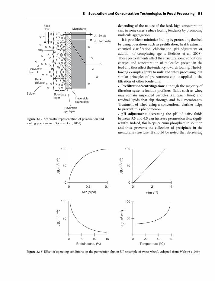
With processing time, performance of filtration opera-tions will inevitably decrease as an extra resistance addsup to the membrane resistance. Two phenomena cancause a decrease in the permeation flux (J) duringfiltration processes: (1) polarization and (2) fouling(Li & Chen, 2010), as represented in Figure 3.17.Although there is no universal definition, polarization
can be described as the reversible accumulation ofdissolved or suspended species near the membrane’ssurface (Li & Chen, 2010). This phenomenon can usuallybe controlled by adjusting hydraulic parameters (i.e. pres-sure, speed of recirculation) to re-establish the permeateflux (J). Fouling refers as the irreversible formation of adeposit of retained particles in the membrane pores(i.e. pore blocking) or surface (i.e. absorption). It resultsin unstable filtration behaviors. In this case, the permeateflux (J) can only be re-established by interrupting theprocess for membrane cleaning. Since membranecleaning involves operation as well as energy costs andaffects the lifetime of membranes fouling is often themain limitation of membrane applications in the foodindustries (Li & Chen, 2010). Fouling can be caused by
3 Separation and Concentration Technologies in Food Processing 49

inorganic compounds (e.g. minerals), microorganisms(e.g. biofilms) or macromolecules (e.g. proteins, carbohy-drates, and fats). This undesired phenomenon affectingproductivity, as well as membrane selectivity, can how-ever be controlled by several parameters such as: thenature and concentration of the feed, the type of mem-brane used, the pore size distribution, membrane mate-rial, and operational conditions (e.g. filtration mode,transmembrane pressure (TMP), temperature, turbu-lence, etc.) (Cui et al., 2010; Li & Chen, 2010).Figure 3.18 illustrates the effect of TMP, recirculationspeed (v), protein concentration, and temperature on per-meation flux (J) in the ultrafiltration of sweet whey.Amongst all factors influencing fouling phenomena,
three major groups are recognized: (1) nature and
concentration of the feed; (2) type of membrane andmembrane material; and (3) operational conditions.
3.4.1.3.1 Nature and concentration of the feed
Fouling phenomena are generally increased in high con-centration feed, as the amount of proteins decrease per-meation flux (J) via an increase in solution viscosity,but mainly by the accumulation of protein in the polari-zation concentration zone (see Figure 3.17). Indeed,macromolecules (e.g. proteins) can form a gel layer athigh concentration or cause cake formation and poreblocking, as hydrophobic molecules (e.g. fatty acids)can be absorbed by the membrane surface. However,
Feed tank
Membrane
module
(a)
Filtrate
Pump
Feed tank
Pump
Retentate
(concentrate)Filtrate
(b)
Figure 3.16 Schematic diagrams of (a) batch and (b) continuous filtration operation modes (Raja, 2008).
50 Food Processing: Principles and Applications
depending of the nature of the feed, high concentrationcan, in some cases, reduce fouling tendency by promotingmolecule aggregation.It is possible tominimize fouling by pretreating the feed
by using operations such as prefiltration, heat treatment,chemical clarification, chlorination, pH adjustment oraddition of complexing agents (Beltsios et al., 2008).Those pretreatments affect the structure, ionic conditions,charges and concentration of molecules present in thefeed and thus affect the tendency towards fouling. The fol-lowing examples apply to milk and whey processing, butsimilar principles of pretreatment can be applied to thefiltration of other foodstuffs.• Prefiltration/centrifugation: although the majority offiltration systems include prefilters, fluids such as wheymay contain suspended particles (i.e. casein fines) andresidual lipids that slip through and foul membranes.Treatment of whey using a conventional clarifier helpsto prevent this phenomenon.• pH adjustment: decreasing the pH of dairy fluidsbetween 5.5 and 6.5 can increase permeation flux signif-icantly. Indeed, this keeps calcium phosphate in solutionand thus, prevents the collection of precipitate in themembrane structure. It should be noted that decreasing
Solute
Back
diffusion
Boundary
layer
Reversible
gel layer
Irreversible
bound layer
Convective
flow
Feed
flow Membrane
Js Solute
PermeateJv
cp
cb
cw
Figure 3.17 Schematic representation of polarization andfouling phenomena (Goosen et al., 2005).
100
50
J (L
·m2·h
–1)
0
0 0.2 0.4
TMP (Mpa)
100
50
J (L
·m2·h
–1)
0
0 2 4
v (m·s–1)
100
50
J (L
·m2·h
–1)
0 5 10 15
Protein conc. (%)
100
50
J (L
·m2·h
–1)
0 20 40 60
Temperature (°C)
Figure 3.18 Effect of operating conditions on the permeation flux in UF (example of sweet whey). Adapted from Walstra (1999).
3 Separation and Concentration Technologies in Food Processing 51

pH usually increases the concentration of free calciumions (Ca2+), which can promote fouling, especially inthe case of ceramic membranes.• Preheating: the positive effects of preheating (50−60�Cfor 30−120 min) on permeation flux are widely exploitedin the manufacture of whey protein concentrates by UF.Heating causes excess calcium phosphate to precipitate,the free calcium ion concentration to decrease, and lipo-proteins to aggregate. Clarification is often needed toremove precipitated material from preheated whey.• Defatting: defatting consists of decreasing the concen-tration of residual lipids, for example in a dairy fluid. It istypically a combination of pH adjustments, heating andclarification or centrifugation. It is possible to obtaindefatted dairy fluids (including milk and buttermilk) bytangential microfiltration, using a membrane of 1.4 μmpore size.• Demineralization/calcium ion sequestration: demin-eralization is also an effective means of preventing theprecipitation of calcium phosphate. Chemicals thatsequester calcium (e.g. EDTA, citric acid) can be usedfor this purpose, but it must be established first that thesequestering agent has no affinity with the membranematerial.
3.4.1.3.2 Type of membrane and membrane material
Membrane properties such as materials, surface morpho-logical structures (e.g. heterogeneity of the pores and poresizes) and surface properties (e.g. smoothness of the sur-faces, hydrophobicity or surface charges) can all modulatethe tendency toward fouling (Brunner, 2005). For exam-ple, hydrophobic membranes (e.g. polysulfone) will tendto adsorb proteins, as hydrophilic ones (e.g. cellulose ace-tate) will have a higher affinity for minerals (e.g. calcium)and be less inclined to fouling. For the reason, a hydro-philic coat is frequently applied on hydrophobic mem-branes in order to minimize fouling phenomena (Li &Chen, 2010).
3.4.1.3.3 Operational conditions
The type of filtration mode and the optimization ofoperational conditions can also minimize fouling. Forexample, compared to cross-flow filtration – in whichthe feed runs tangential to the membrane – dead-endfiltration will promote cake formation, as large molecules(i.e. larger than the pores) are stopped at the membrane’ssurface. Indeed, cross-flow technique prevents filter cakeformation (see Figure 3.14).
Adjustments of TMP, temperature of operation as wellas the use of turbulence promoters can all decrease the ten-dency toward fouling. An increased pressure can compactthe existing filter cake and thus, negatively affect the foulingphenomena. An higher recirculation speed amplifies theshear rate near themembrane’s surface and reduces the riskof protein gelling. Similarly, an increased inTMPcan some-times optimize the permeate flux in cases where recircula-tion speed is sufficient to maintain a turbulent regime.However, in some case, but in some cases, the resultingincreases of the driving force favorably affect polarizationby increasing the foulant’s compaction (Li & Chen, 2010).An higher temperature can also lead to an improvementin permeate flux by reducing viscosity and increasing thepermeability of the membrane material. However, it isimportant to remember that processing temperatures above60�C denature many proteins, which not only affects theirfunctional properties but will also make them more liabletoparticipate in irreversible foulingof themembrane.More-over, the temperature is limited by the thermal resistance ofthemembranematerial (Li &Chen, 2010). Finally, it is pos-sible to reducemembrane foulingwith: (1) the use of turbu-lence promoters, which decreases concentration near thesurface, and (2) backflushing, which removes cake layers(Cui et al., 2010). An electric field across the membrane(i.e. electrofiltration), pulsed flow (i.e. fluctuating pressure),androtatingorvibratingdynamicmembranesystemsare allused to reduce fouling and the polarization phenomena(Fane & Chang, 2008).In conclusion, control of fouling and polarization
phenomena can be achieved by controlling the composi-tion and physicochemical properties of the fluid to beprocessed and by optimizing the filtration system’sperformance parameters.
3.4.1.4 Applications of membranes in food processing
Membranes used by the food processing industry represent20−30% of all worldwide membrane sales. This marketis growing at a fast annual rate of around 7.5%(Mohammad et al., 2012).Mainly used in the dairy industry(close to 40% of all use), membrane technology is also usedfor beverages, sugar refining, and oil processing.Membraneprocesses are advantageous for environmental, competitiveand economic reasons, and they also allow for the produc-tion of high-quality food products, from a nutritional andfood safety point of view. They are mainly used for concen-tration purposes in the food industry. Around 58% ofthe membrane market is represented by MF membrane,followed by UF and RO membranes (around 17% each).
52 Food Processing: Principles and Applications

The remaining 8% represents the othermembrane technol-ogies, such as NF, pervaporation (2%), and electrodialysis.Moreover, membrane technologies simplify conventionalprocessing methods by removing processing steps, are easytooperate, and can improveprocess performances (e.g. clar-ification) (Daufin et al., 2001). RO represents the most eco-nomical preconcentration method in food processing andthus can generate enormous energy savings for industries(Munir, 2006).
3.4.1.4.1 Dairy industry (UF or MF of milk, cheesewhey, dairy effluents)
Milk is a complex mixture of different types of moleculesincluding proteins, lipids, lactose and minerals, but alsocontains undesirable components such as bacteria. Inthe dairy industry, membrane technologies are used toconcentrate and separate milk and milk by-product com-ponents, thus adding to their commercial value. Actually,whey processing represents the main application of mem-brane technology in the dairy industry, with more than75% of all membrane usages (Mohammad et al., 2012).Tangential flow or cross-flow MF, the uniform trans-
membrane pressure (UTP) concept, and ceramic-basedmembrane improvements have all contributed to theincreased utilization of MF in dairy processing(Saboya & Maubois, 2000). There are three major appli-cations of MF in the dairy industry: (1) the removal ofbacteria from milk; (2) the pretreatment of cheese whey(i.e. defatting and removal of bacteria); and (3) the micel-lar casein enrichment of cheese milk. Indeed, in the dairyindustries, MF is used to produce longer shelf life pro-ducts (i.e. 16−21 days compared to 6−8 days for conven-tional pasteurization processes) without cooked off-tastesand with a greater reduction of spore-forming bacteria(Philipina & Syed, 2008). In fact, 99.99% of bacteria canbe removed from skimmilk using a commercial MF proc-ess called Bactocatch® (Tetra Laval, Lund, Sweeden).This process, employing an 1.4 μm MF membrane (50 �
C, 0.5 bar), has been used commercially mainly in Canadaand western Europe (Elwell & Barbano, 2006). It shouldbe noted that, for legal as well as safety considerations,all MF milk commercialized in U.S. and Canada needsto be further pasteurized.Microfiltration has also been proposed as an effective
method to remove fat from whey before further proces-sing by UF. Indeed, compared to the conventionalpretreatments used in the industry (i.e. clarificationfollowed by pasteurization), MF removes phospholipo-protein complexes as well as all residual lipids, even
the smallest milk fat globules (Li & Chen, 2010). It ispossible to increase the UF permeation flux by 30% bypretreating cheese whey using MF before concentration.Moreover, MF can retain valuable whey proteins such asbovine serum albumin and immunoglobulin-G, whichcan be useful for functional food applications (Morr &Ha, 1993). The pretreatment of cheese whey by MFallows the production of high-quality, low-fat “undena-tured” whey protein concentrate (WPC), and wheyprotein isolate (WPI) (Smithers, 2008). Finally, MFcan be utilized in cheese making to change the casein-to-whey protein ratio or the casein-to-fat ratio. In fact,the application of the MF process to whole milk allowsfor the production of an enriched native and micellarcalcium phosphocaseinate retentate which improvesrennet coagulation and thus, productivity of cheese man-ufactures (Li & Chen, 2010). Moreover, by using a 3%phosphocaseinate solution, it is possible to reduce thecoagulation time by 53% and increase the firmness (after30 min) of more than 50% in comparison to raw milk(Daufin et al., 2001).Ultrafiltration is the most commonly used membrane
process in the world’s dairy industry (Daufin et al.,2001). The fractionation and concentration of whey pro-tein represent the most important industrial applicationof UF in the dairy industry. The whey protein UF concen-trates can be further purified using DF to obtain high-purity WPC and WPI. Since all proteins in skim areretained and concentrated by UF, concentration and puri-fication of milk protein to produce milk protein concen-trates (MPC) and isolates (MPI) also represent a mainapplication of UF in dairy processing. UF-MPC are exten-sively used by soft cheeses manufacturers as pre-cheese tobe coagulated and fermented (Philipina & Syed, 2008).This process allows the full retention of whey proteins inthe cheese matrix and thus eliminates whey drainageand reduces rennet requirement by around 80% comparedto conventional cheese-making methods (Elwell & Bar-bano, 2006). However, bitterness problems have beenreported in soft cheeses as well as texture defaults insemi-hard and hard cheeses (Elwell & Barbano, 2006).UF ofmilk generates, as a co-product, protein-free perme-ate which may subsequently be NF-processed to recoverlactose. Finally, UF is also used to standardize milk bythe adjustment of the mass ratio to the different milkconstituents.Nanofiltration is somewhat similar to UF and is com-
monly used in the industry for the processing of UF andMF permeates (Philipina & Syed, 2008). Indeed, the mainapplication of NF in the dairy industry is the desalting
3 Separation and Concentration Technologies in Food Processing 53

of whey permeates (Munir, 2006). As with RO, it can beused for the preconcentration of milk or whey (by theremoval of water and minerals) mainly to reduce trans-portation costs or energy requirements before the evapo-ration process (Munir, 2006).
3.4.1.4.2 Fruit and vegetable juices (clarificationand concentration of fruit juice)
Clarification, concentration, and deacidification are themain uses for membrane technology in fruit juices pro-cessing (i.e. around 20% of all membrane usages). Con-centration of fruit and vegetable juices has economicadvantages for packaging, storage, and distribution.Moreover, membrane processes avoid color degradationand cooked off-tastes, as well as the loss of delicate aromasimportant to fresh juice flavors (Munir, 2006).Ultrafiltration is used in the processing of multiple fruit
and vegetable juices such as orange, lemon, grapefruit,tangerine, tomato, cucumber, carrot, and mushroom(Mohammad et al., 2012). Typically, juice is extractedusingapress andpassed throughaUFmoduleprior to con-centration by evaporation or furthermembrane processes.UF membranes retain the concentrated pulp fraction (i.e.retentate) as well as unwanted enzymes. The UF-clarifiedpermeate obtained can be pasteurized and, if needed, fur-ther concentrated. Most of the bioactive compounds arerecovered in the permeate using this technology. Thereaf-ter, pasteurized pulp can be reincorporated to the clarifiedpermeate fraction to obtain whole juice. In the industry,pretreatment of fruit by enzymes (e.g. pectinases and cel-lulases) is commonly applied to improve fruit juice extrac-tion, to reduce juice viscosity, and improve juice yield andcolor. Theuse of immobilized pectinases onUFmembranehas been proposed as a method to allow the reuse ofenzymes while controlling membrane fouling during clar-ification processes (Giorno & Drioli, 2000).Reverse osmosis favorably concentrates fruit juices,
giving high-quality products in which both nutritionaland sensorial qualities are maintained by the low temper-ature used in the process. However, RO gives a low con-centration level (25�Brix) compared to evaporation (42−65�Brix) (Jesus et al., 2007). Recently, a new methodcalled “high-concentration RO” has been described forthe concentration of orange and apple juices, using thecombination of two membranes (Echavarría et al., 2011;Munir, 2006). A first membrane retains sugars and aromacomponents (i.e. retentate), which can then be processedusing a second membrane that allows some of the sugars
to pass through. The result is a lower transmembraneosmotic pressure differential and a concentrated reten-tate (42−60�Brix) with organoleptic properties close tothose of fresh juice with no loss of acids, vitamin C,limonene, or pectin (Munir, 2006). This process has somedisadvantages including generation of a diluted, low-valueby-product, and the need for complex and high-costsystems (Merry, 2010).
3.4.1.4.3 Sugar refining (concentration, clarification,and purification)
Traditionally, sugar syrup concentration is performedusing evaporation.This is energy consumingandcan lowerthe quality of the sugar and negatively influence its color.Membrane processes represent an alternative to evapora-tion in sugar refining for concentration purposes. It canalso be used for clarification and purification applications.Indeed, raw juices from sugar cane or sugar beet containnot only sucrose, but various polysaccharides, proteins,gums, and other unwanted components. Those impuritiesare traditionally removed using anionic resins which gen-erate polluting elutes (Daufin et al., 2001). Industrial clar-ification of raw sugar juices by UF or MF is rapidlygrowing, due to their greater capacity to remove unwantedmacromolecules and microorganisms compared to tradi-tional methods. Membrane processes remove unwantedmaterials (i.e. retentate) and give a decolorized raw sugarjuice (i.e. permeate) ready for concentration and crystalli-zation. Concentration of sugar juices by RO or NF iscost-effective compared to evaporation. The use of NF asa preconcentration step can reduce the loss of sugars inthe molasses by 10% (Madaeni et al., 2004; Munir,2006). RO has been used for the concentration of maplesyrup, resulting in more than 30% reduction in processingcosts (Munir, 2006).
3.4.1.4.4 Vegetable oils processing
The production of edible oils follows a series of stepsnecessary for proper product quality by the removal ofimpurities such as water, dust, phospholipids, free fattyacids, gums, waxes, oxidation products, pigments,and trace elements (e.g. iron, copper, and sulfur). Theseprocesses include degumming, deacidification/neutraliz-ation, bleaching, dewaxing and deodorization. Thoselatter processing steps mostly involve high temperatures,the use of harsh chemicals and of considerableamounts of energy in the form of steam or electricity.Membrane-based processes (i.e. MF, UF, NF) can
54 Food Processing: Principles and Applications

practically replace all the steps necessary for edible oilsprocessing in a simple, competitive and eco-friendlyway (Ladhe & Krishna Kumar, 2010). However, develop-ment of membranes allowing higher flux and selectivitycombined to less fouling is still necessary to the replace-ment of critical energy-costing steps (i.e. degumming,refining, and bleaching) in commercial applications(Lin & Koseoglu, 2005).Furthermore, membrane-based technologies can
advantageously remove oxidation products as well asheavy metal traces. Indeed, with regard to their abilityto remove oxidation products, membrane processes havebeen proposed as a method to extend the life-span of fry-ing oils by the removal of proteins, carbohydrates andtheir decomposition products, and prevent color changes(Snape & Nakajima, 1996).Membrane technologies can also be used to recover veg-
etable protein from oil extracting residues. For example,UF has been successfully applied to obtain soy protein iso-lates (i.e. 60–65% of proteins) from the defatted soybeanmeal or “cake” (Ladhe & Krishna Kumar, 2010). The iso-late obtained presents good nutritional value and can beused in breakfast cereals, animal nutrition, confectionery,and dairy imitation products, as well as in nutritional anddietary beverages (Koseoglu & Engelgau, 1990).Although membrane technologies can advantageously
replace some of the steps in edible oils processing, onlya few commercial applications have been reported.Nitrogen production for packaging uses, waste watertreatment using UF/RO and phospholipids removal usingMF have been descrided in litterature (Lin & Koseo-glu, 2005).
3.4.1.4.5 Brewing and wine industry
Beer is the second most consumed beverage in the world.This industry is constantly being challenged to createproducts with consistent quality and unique taste whilemaintaining low production costs and environmentallyfriendly process (Carmen & Ernst Ulrich, 2008). Mem-brane technology applications are emerging as theyenhance product quality, are energy saving, and reducewater waste.The production of beer involves mashing, boiling,
fermentation, andmaturation steps followed by a pasteur-ized process to ensure microbiological stability and con-servation. During brewing, several filtration operationsare essential to remove solids particles (e.g. yeasts, malt,and hops) from the product. This separation of solid from
liquid, traditionally done by dead-end filtration on diato-maceous earth (DE), represents a challenge for economic,environmental, and technical purposes. Indeed, the DEused for traditional filtration is difficult to handle andthus represents a potential health hazard. Also, it needsto be properly disposed after usage and involves addi-tional filtration steps.Microfiltration is mainly used in the brewing indus-
try for the recovery of beer from fermentation andmaturation tank bottoms, and is considered as anindustrial standard. Indeed, at the end of the fermen-tation and maturation of lager type beers, yeast cellssediment at the bottom of tanks to form yeast slurrywhich represents around 2.5% of the final fermentedproduct volume (Carmen & Ernst Ulrich, 2008).For obvious economic reasons, it is important formanufacturers to recover as much beer as possiblefrom this slurry. Moreover, MF is emerging as a tech-nology used for the separation of wort following themashing step, for rough beer clarification (currentlyused by Heineken breweries), and for cold steriliza-tion (i.e. to replace flash pasteurization) (Daufinet al., 2001). Elimination of heating process by theuse of MF avoids the occurrence of organolepticdefaults, and it is more and more used in thecool-sterilization of beer and wine (Baker, 2004).MF can be used not only to improve microbiologicalstability of wine, it can also ensure clarity of the prod-uct (Daufin et al., 2001). Moreover, RO can be usedfor concentration purposes as well as for dealcoholi-zation. In contrast, it can be used to increase alcoholcontent (Girard et al., 2000). However, RO of winecan produce a concentrate with excessive malic acid,leading to taste faults. Recently, membrane processeshave been employed for beer decolorization in theproduction of clear alcohol to be used in beer-baseddrink premixes (Carmen & Ernst Ulrich, 2008).
3.4.2 Other membrane-based processes
3.4.2.1 Electrodialysis (electrically assisted processes)
Electrodialysis (ED) is a membrane-type electrochemicalprocess whereby membranes are used to separate ionicmolecules from non-ionic ones using electric field asthe driving force for separation. ED membranes are madeof porous (i.e. nanometer range) ion exchange resinswhich selectively separate anion and cation species fordilution/concentration applications. In ED processes,
3 Separation and Concentration Technologies in Food Processing 55

anion-permeable or “anionic” membranes are made ofresin bearing fixed cationic groups, while cation-permeable or “cationic” membranes are made of resinbearing fixed anionic groups. In practice, anionic and cat-ionic membranes are arranged alternately and are sepa-rated by spacers to form thin compartments (the stackunit). Each compartment is either for dilution or for con-centration purposes, and electrodes are place at both endsof the system (Figure 3.19). In the industry, 100−200mem-branesmay be disposed to form a stack unit, and industrialED systems are composed of one or more stack units.By the application of an electric field, anion species perme-ate throughout the anionic membranes in the oppositedirection to the electric current while cations migrate, inthe same direction as the electric current, throughout thecationic membranes (Brennan & Grandison, 2012).In a simplified version of an ED system illustrated in
Figure 3.19a, anions move towards the anode and exitfrom the left compartment by passing through an anionicmembrane, as a cationic membrane keeps them in thecenter compartment. In the same way, cations leave theright compartment by passing through a cationic mem-brane but are trapped in the center compartment becauseof the repletion of the anionic membrane. The result isthat, simultaneously, the pumped feed is ion depletedand the final product recovered from the adjacent com-partments, called the concentration compartments, ision-enriched (Munir, 2006). This process has the singu-larity of leaving the concentration in dissolved non-ioniccompounds unchanged. Indeed, even if proteins or othercharged macromolecules are attracted by the electric field,their high molecular weights do not allow for permeationthroughout the membranes.Bipolar-membrane ED uses special multilayer mem-
branes to dissociatewater inH+ andOH– ions as an electricfield is applied. Bipolar membranes are composed of threelayers: (1) an anion exchange layer; (2) a hydrophilic inter-face; and (3) a cation exchange layer (Bazinet et al., 1998).As illustrated in Figure 3.19b, when those membranes areadded to a conventional ED unit, it allows for the conver-sion of a neutral salt stream to an acid and base one. Thistechnology is of particular interest to food processingif the product to be treated is an acid or a base.The main application of ED in the food industry is the
desalination of cheese whey, but it can also be used to con-centrate, purify, or modify foods (Bazinet et al., 1998). EDapplications include the removal of calcium from milkand lactic acid from whey, the control of sugar/acid ratioin wine, the pH control of fruit juices and fermentationreactors, and the purification of bioactive peptides.
As for all the other membrane processes, ED membranesare susceptible to polarization and fouling and thus, themaximum salt removal attainable by this method isaround 90% (Brennan & Grandison, 2012).
3.4.2.2 Pervaporation
Pervaporation is a relatively new membrane separationprocess and represents one of the most active research
Depleted
feed
stream
(a)
Feed
Product
A C
– ++
–
+
–
+
–
+
–Cath
ode
Anode
C
H+ H+
H+
–
+
–
+
H+
OH– OH–
OH–OH–
A C A C A
Na+OH–
Feed (Na+Ac–)
H2O
H+Ac–Depleted
feed
stream
–
Cath
ode
Anode
+
(b)
Figure 3.19 Schematic diagrams of (a) conventional electrodi-alysis unit and (b) bipolar electrodialysis unit (Munir, 2006).
56 Food Processing: Principles and Applications

areas in membrane technology. Unlike MF, UF, NF, RO,and ED, pervaporation is a pressure-driven membranewhere the permeate generated is a low-pressure vapor,not a liquid, that can be condensed and collected or furtherconcentrated (Feng&Huang, 1997). Using pervaporation,feed containing volatile components is fractionated whenit partially vaporizes and passes through a dense or non-porous selective membrane (Karlsson & Tragardh,1996). The driving force for separation is the chemical gra-dient across the membrane, but a vacuum is commonlyapplied on the permeate side to create an artificial pressuregradient, as shown in Figure 3.20.Pervaporation is considered as a three-step process: (1)
absorption, (2) diffusion, and (3) evaporation (or desorp-tion). In the solution stage, the vaporizing component isdrawn into the membrane at the upstream interface bychemical affinity. It then diffuses through the membraneand desorbs from the downstream interface as the mem-brane selectively allows for the desired components to per-meate through, as vapor. The partial vaporization of thefeed through the membrane is responsible for the separa-tion ability of the pervaporation (Karlsson & Tragardh,1996). Since the chemical composition of the membranedetermines which components will permeate, a hydro-philic membrane can thus be used to dehydrate organicsolutions, while a hydrophobic membrane is suitable forextracting organic components from aqueous solutions.Pervaporation is a useful alternative for liquid mix-
tures that are difficult to separate by distillation and iscommercially used for alcohol dehydration. In the foodindustry, pervaporation can be used to concentrate fruit
juices, alcohol in fermentation broth, dealcoholization ofalcoholic beverages (i.e. final product of 0.5% v/v ofethanol), and recovery and concentration of aroma com-pounds (Karlsson & Tragardh, 1996). The latter is prob-ably the most promising application of pervaporation infood processing. Conventional concentration processessuch as evaporation, inevitably result in aroma com-pound losses, due to their highly volatile nature. Perva-poration can be used on raw materials, prior toevaporation to concentrate aroma (i.e. at least 100-foldgreater than in the raw material), or on the resultingstream to recover lost aroma. Aroma compounds canthen be reintroduced in the final product to ensure tasteacceptability (Karlsson & Tragardh, 1996). Compared toother aroma recovery processes, pervaporation operatesat low temperature (i.e. 20�C), which eliminates damagedue to high heat and allows for energy savings.In the dealcoholization application of pervaporation,
an important concern is the loss of aroma compounds inthe ethanol phase – due to their very hydrophobic nature.However, new techniques using pervaporation allow forthe production of 0.5% (v/v) alcohol wine with more than80% aroma retention (Karlsson & Tragardh, 1996). Perva-poration has also been proposed as a deodorization processfor food industry effluents. It simultaneously allows therecovery, the concentration, and the valorization of flavorcompounds fromindustrialwastes (Galanakis, 2012).How-ever, pervaporation is in a less advanced state than all othermembrane processes presented in this section, and under-standing of the separation mechanisms is still incomplete.Further research is needed before large-scale pervaporationcan be widely promoted (Feng & Huang, 1997).
3.5 Sustainability of separationtechnologies in food processing
In food industry separation technologies, sustainabilityproblems are mainly related to two factors: (1) energy,and (2) water consumption. As noted by Muralidhara(2010), of the 100 quads (1 quad = 1015 BTU/year) ofenergy consumed in the United States, food processinguses approximately 2 quads. At a cost of $8 per 106
BTU, this amounts reaches $16 billion per year. Half ofthis energy is used for concentration and drying purposes.For example, corn (wet) milling uses 93.7 trillion BTU,grain milling 153.3 trillion BTU, and vegetable oil proces-sing 2.0 trillion BTU each year. Thus, there are opportu-nities for the integration of membrane technology to thefood industry’s separation and concentration processes in
Feed
PV membraneNoncondensables
Vacum
pump
ProductVaporLiquid
Condenser
Figure 3.20 Schematic diagram of pervaporation of atwo-component system (Munir, 2006).
3 Separation and Concentration Technologies in Food Processing 57

many kinds of applications. As a purely physicalseparation, membrane concentration does not requirea heat-producing unit, or a phase change (from liquidto vapor), and it can partially or totally replace energy-consuming processes (e.g. distillation and evaporation).It thus results in not only in major energy savings, butin higher product quality. Modern filtration units arecompact, efficient, simple, highly selective (i.e. to specificcompounds), reduce chemical production, and offer oper-ation flexibility to integrate hybrid processes. They repre-sent part of the solution to quality, energy, space, andenvironmental concerns (Merry, 2010). Moreover, mem-brane technologies allow for the re-use and recovery of allprocess streams, without damage to the environment.Food processing also consumes large volumes of water
which are a major concern for the environment.Advanced membrane technologies represent a solutionto polluting, high-energy, space-consuming, conventionalwaste water complex processes (Madaeni et al., 2004).Indeed, process effluents are today being treated usingmembrane processes such as RO, UF, and ED and treatedeffluents are being reused in plants for different purposessuch as washing.In conclusion, membrane technologies have a promis-
ing future and may be considered as important tools forthe efficient use of processing streams without pollutingdischarges with regard to energy savings, environmental,and quality regulations.
References
Baker RW (2004) Microfiltration. In:Membrane Technology andApplications. New York: John Wiley, pp. 275–300.
Bargale P (1997) Mechanical Oil Expression from Selected Oil-seeds under Uniaxial Compression. Saskatoon: Departmentof Agricultural and Bioresource Engineering, University ofSaskatchewan, p. 337.
Barta J, Balla C, Vatai G (2012) Dehydration preservation offruits. In: Handbook of Fruits and Fruit Processing. New York:Wiley-Blackwell, pp. 133–151.
Bazinet L, Lamarche F, Ippersiel D (1998) Bipolar-membraneelectrodialysis: applications of electrodialysis in the food indus-try. Trends in Food Science and Technology 9(3): 107–113.
Beltsios KG et al (2008) Membrane science and applications.In: Handbook of Porous Solids. Weinheim, Germany:Wiley-VCH, pp. 2281–2433.
Berk Z (2009a) Crystallization and dissolution. In: Food ProcessEngineering and Technology. New York: Academic Press,pp. 317–331.
Berk Z (2009b) Evaporation. In: Food Process Engineering andTechnology. New York: Academic Press, pp. 429–458.
Berk Z (2009c) Extraction. In: Food Process Engineering andTechnology. New York: Academic Press, pp. 259–277.
Brennan G, Grandison AS (2012) Food Processing Handbook.New York: John Wiley, pp. 275–300.
Brunner G (2005) Supercritical fluids: technology and appli-cation to food processing. Journal of Food Engineering67(1–2): 21–33.
Carmen M, Ernst Ulrich S (2008) Applications of membraneseparation in the brewing industry. In: Handbook of Mem-brane Separations. Boca Raton, FL: CRC Press, pp. 553–579.
Cui ZF, Jiang Y, Field RW (2010) Fundamentals of pressure-driven membrane separation processes. In: Cui ZF, Muralid-hara HS (eds)Membrane Technology. New York: Elsevier But-terworth-Heinemann, pp. 1–18.
Daufin G, Escudier J, Carrere H et al. (2001) Recent and emer-ging applications of membrane processes in the food and dairyindustry. Food and Bioproducts Processing 79(2): 89–102.
Echavarría A, Torras C, Pagan J, Ibarz A (2011) Fruit juice pro-cessing and membrane technology application. Food Engi-neering Reviews 3(3): 136–158.
Elwell MW, Barbano DM (2006) Use of microfiltration toimprove fluid milk quality. Journal of Dairy Science 89(suppl):E20–E30.
Fane A, Chang S (2008) Techniques to enhance performanceof membrane processes. In: Handbook of Membrane Separa-tions. Boca Raton, FL: CRC Press, pp. 193–232.
Fellows PJ (2009) Food Processing Technology – Principles andPractice, 3rd edn. Cambridge: Woodhead Publishing.
Feng X, Huang RYM (1997) Liquid separation by membranepervaporation: a review. Industrial and Engineering Chemis-try Research 36(4): 1048–1066.
Galanakis CM (2012) Recovery of high added-value componentsfrom food wastes: conventional, emerging technologies andcommercialized applications. Trends in Food Science andTechnology 26(2): 68–87.
Giorno L, Drioli E (2000) Biocatalytic membrane reactors:applications and perspectives. Trends in Biotechnology18(8): 339–349.
Girard B, Fukumoto LR, Koseoglu S (2000) Membrane proces-sing of fruit juices and beverages: a review. Critical Reviewsin Biotechnology 20(2): 109–175.
Goosen MFA, Sablani S, Al-Hinai H et al. (2005) Fouling ofreverse osmosis and ultrafiltration membranes: a criticalreview. Separation Science and Technology 39(10): 2261–2297.
Grandison AS, Lewis MJ (1996) Separation Processes in the Foodand Biotechnology Industries: Principles and Applications.Cambridge: Woodhead Publishing.
Hartel RW (2001) Crystallization in Foods. New York: AspenPublishers.
58 Food Processing: Principles and Applications
Hasenhuettl GL (2005) Fats and fatty oils. In: Kirk-Othmer Ency-clopedia of Chemical Technology. New York: John Wiley, pp.801–836.
Jesus DF, Leite M, Silva L et al. (2007) Orange (Citrus sinensis)juice concentration by reverse osmosis. Journal of Food Engi-neering 81(2): 287–291.
Jirjis BF, Luque S (2010) Practical aspects of membranesystem design in food and bioprocessing applications.In: Cui ZF, Muralidhara HS (eds) Membrane Technology.New York: Elsevier Butterworth-Heinemann,pp. 179–212.
Karlsson HOE, Tragardh G (1996) Applications of pervapora-tion in food processing. Trends in Food Science and Technol-ogy 7(3): 78–83.
Kazmi A (2012) Advanced Oil Crop Biorefineries. London: RoyalSociety of Chemistry, pp. 102–165.
Khan LM, Hanna MA Expression of oil from oilseeds – areview. Journal of Agricultural Engineering Research 28(6):495–503.
Koseoglu S, Engelgau D (1990) Membrane applicationsand research in the edible oil industry: an assessment.Journal of the American Oil Chemists' Society 67(4):239–249.
Kubota N, Hashimoto T, Mori Y (2008) Microfiltration andultrafiltration. In:AdvancedMembrane Technology and Appli-cations. New York: John Wiley, pp. 101–129.
Kumar A (2009) Bioseparation Engineering: A ComprehensiveDSP Volumen. New Delhi: I.K. International Publishing.
Ladhe AR, Krishna Kumar NS (2010) Application of membranetechnology in vegetable oil processing. In: Cui ZF, Muralid-hara HS (eds)Membrane Technology. New York: Elsevier But-terworth-Heinemann, pp. 63–78.
Leung WWF (2007) Centrifugal Separations in Biotechnology.New York: Academic Press.
Li H, Chen V (2010) Membrane fouling and cleaning in food andbioprocessing. In: Cui ZF, Muralidhara HS (eds) MembraneTechnology. New York: Elsevier Butterworth-Heinemann,pp. pp. 213–254.
Li X, Du Y, Wu G et al. (2012) Solvent extraction for heavy crudeoil removal from contaminated soils. Chemosphere 88(2):245–249.
Lin L, Koseoglu S (2005) Membrane processing of fats and oils.In: Bailey's Industrial Oil and Fat Products. New York:John Wiley, pp. 57–98.
Madaeni SS, Tahmasebi K, Kerendi SH (2004) Sugar syrup con-centration using reverse osmosis membranes. Engineering inLife Sciences 4(2): 187–190.
Merry A (2010) Membrane processes in fruit juice proces-sing. In: Cui ZF, Muralidhara HS (eds)Membrane Technol-ogy. New York: Elsevier Butterworth-Heinemann, pp.33–43.
Mohammad A, Ng CY, Lim YP, Ng GH (2012) Ultrafiltration infood processing industry: review on application, membranefouling, and fouling control. Food and Bioprocess Technology5(4): 1143–1156.
Morr CV, Ha EYW (1993) Whey protein concentrates andisolates: processing and functional properties. Critical Reviewsin Food Science and Nutrition 33(6): 431–476.
Munir C (2006) Membrane concentration of liquid foods.In: Handbook of Food Engineering, 2nd edn. Boca Raton,FL: CRC Press, pp. 553–599.
Muralidhara HS (2010) Challenges of membrane technology inthe XXI century. In: Cui ZF, Muralidhara HS (eds)MembraneTechnology. New York: Elsevier Butterworth-Heinemann,pp. pp. 19–32.
Otles S (2008) Handbook of Food Analysis Instruments.New York: Taylor and Francis.
Philipina M, Syed R (2008) Applications of membrane technol-ogy in the dairy industry. In: Handbook of Membrane Separa-tions. Boca Raton, FL: CRC Press, pp. 635–669.
Raja G (2008) Ultrafiltration-based protein bioseparation.In: Handbook of Membrane Separations. Boca Raton, FL:CRC Press, pp. 497–511.
Rizvi SSH (2010) Separation, Extraction and Concentration Pro-cesses in the Food, Beverage and Nutraceutical Industries.Cambridge: Woodhead Publishing.
Rosenthal A, Pyle DL,NiranjanK (1996) Aqueous and enzymaticprocesses for edible oil extraction. Enzyme and MicrobialTechnology 19(6): 402–420.
Rydberg J, Cox M, Musikas C (2004) Solvent Extraction Princi-ples and Practice. New York: Marcel Dekker.
Saboya LV, Maubois JL (2000) Current developments of micro-filtration technology in the dairy industry. Lait 80(6):541–553.
Sahena F, Zaidul I, Jinap S et al. (2009) Application of super-critical CO2 in lipid extraction – a review. Journal of FoodEngineering 95(2): 240–253.
Savoire R, Lanoisellé JL, Vorobiev E (2013) Mechanical contin-uous oil expression from oilseeds: a review. Food and Biopro-cess Technology 6(1): 1–16.
Singh RP, HeldmanDR (2008) Introduction to Food Engineering.New York: Academic Press.
Sinnott RK (2005) Coulson and Richardson’s Chemical Engineer-ing, Volume 6 – Chemical Engineering Design, 4th edn.New York: Elsevier Butterworth-Heinemann.
Smithers GW (2008) Whey and whey proteins – from ‘gutter-to-gold’. International Dairy Journal 18(7): 695–704.
Snape JB, Nakajima M (1996) Processing of agricultural fats andoils using membrane technology. Journal of Food Engineering30(1–2): 1–41.
Sutherland K (2008) Filters and Filtration Handbook. New York:Elsevier Butterworth-Heinemann.
3 Separation and Concentration Technologies in Food Processing 59

Takeuchi TM, Pereira CG, Braga M et al. (2008) Low-pressuresolvent extraction (solid–liquid extraction, microwaveassisted, and ultrasound assisted) from condimentaryplants. In: Meireles MAA (ed) Extracting Bioactive Com-pounds for Food Products. Boca Raton, FL: CRC Press,pp. 137–218.
Turner C (2006) Overview of modern extraction techniquesfor food and agricultural samples. In: Modern Extraction
Techniques. Washington, DC: American Chemical Society,pp. 3–19.
Voet D, Voet JG (2005) Biochemistry. New York: John Wiley.
Vose JR (1978) Separating grain components by airclassification. Separation and Purification Reviews 7(1):1–29.
Walstra P (1999) Dairy Technology: Principles of Milk Propertiesand Processes. New York: Marcel Dekker.
60 Food Processing: Principles and Applications