sensors - sprinkler talk
TRANSCRIPT

SE N S O R
S
P R O D U C T I N F O R M A T I O N
SensorsSimple, Accurate, Rugged and Reliable
Rain, Freeze, Wind, and Flow Sensors


3
TABLE OF CONTENTS
Sensors
Sensor Product Category Overview ................................................................................................................. 4Rain SensorsRain Sensor Product Comparison .................................................................................................................... 4Rain-Clik™ / Wireless Rain-Clik™ ................................................................................................................ 5
Product Features and Benefits .................................................................................................................. 5Troubleshooting ........................................................................................................................................ 7Installation and Maintenance ................................................................................................................... 8
Wireless Rain-Clik ......................................................................................................................................... 10Product Features and Benefits ................................................................................................................ 10Troubleshooting ...................................................................................................................................... 12
Mini-Clik® Rain Sensor ................................................................................................................................. 13Product Features and Benefits ................................................................................................................ 14Installation Instructions .......................................................................................................................... 15Troubleshooting ...................................................................................................................................... 18Frequently Asked Questions ................................................................................................................... 18Replacement Parts .................................................................................................................................. 19
Wind SensorWind-Clik® Wind Sensor ............................................................................................................................... 19
Product Features and Benefits ................................................................................................................ 19Freeze SensorFreeze-Clik® Freeze Sensor ........................................................................................................................... 20
Product Features and Benefits ................................................................................................................ 21Installation Instructions .......................................................................................................................... 21
Weather StationMini-Weather Station ..................................................................................................................................... 23
Product Features and Benefits ................................................................................................................ 23Weather Sensor Options ................................................................................................................................. 24Flow SensorsFlow-Clik™ Flow Sensor .............................................................................................................................. 25
Product Features and Benefits ................................................................................................................ 25Flow-Clik System Overview .................................................................................................................. 28Installation Instructions .......................................................................................................................... 29Troubleshooting Guide ........................................................................................................................... 34Specifications .......................................................................................................................................... 35
Flow Sensor Product Comparison ................................................................................................................. 35Sensors Training Manual Quiz ...................................................................................................................... 36
Quiz Answers .......................................................................................................................................... 37

SE N S O R
S
4
SENSOR PRODUCT CATEGORY OVERVIEW
When you are concerned with water waste, Hunterʼs sensing devices backed by a 5-year warranty need to be a part of your irrigation system.
Weather SensorsThe simplest, most effective way to prevent an irriga-tion system from operating during or after inclement weather is to use Hunter Weather Sensor Devices. Easily installed on any automatic irrigation system, the Weather Sensors shut sprinklers off during rain, wind or freezing temperatures. These sensors are designed to temporarily shut off the irrigation system based on specific sensor settings and then automatically allow for resumption of irrigation without ever affecting the irrigation system controller settings. Built to withstand the harshest conditions, thereʼs no better way to ensure that your system isnʼt watering when it shouldnʼt be.
Flow SensorsHunter Flow Sensors continuously monitor water flow that is passing through the flow sensing device during irrigation system operation. If the flow sensor identi-fies a flow rate that is higher than a predetermined amount by the user, the device will communicate to the controller to shut down that particular valve and
prevent its future operation until the flow is normal-ized to the desired level. The device can shut down the irrigation system as a result of a ruptured mainline, a broken lateral line or a damaged sprinkler, thereby reducing wasted water, and damage caused by erosion and flooding.
Hunter Flow Sensors offer an affordable insurance policy that will dramatically reduce your liability exposure if you experience a catastrophic failure due to a “high-flow” situation with regards to your irriga-tion system.
RAIN SENSOR PRODUCT COMPARISON
FeaturesHunter®
Rain-Clik™Hunter® Wireless
Rain-Clik™
Hunter® Mini-Clik®
Rain Bird Rain Check™
Rain Bird RSD
TORO Rain Switch®
Weath-ermatic
Rain-Stat
Rain Bird WRC
Irritrol RS1000
Quick Response™ feature for cloudbursts
✔ ✔
Rain gutter mount ✔ ✔ ✔
Vertical/Horizontal mount ✔ ✔ ✔ ✔ ✔ ✔ ✔ ✔
Set a custom dry-out time period
✔ ✔ ✔ ✔ ✔ ✔
Wireless operation ✔ ✔ ✔
No-Maintenance mechanism ✔ ✔ ✔ ✔ ✔ ✔ ✔
25' of Control Wire Included ✔ no wires required
✔ ✔ no wires required
no wires required
5-Year warranty ✔ ✔ ✔ 3 year ✔ 2 year 2 year 3 year 5 year
Maintenance-Free 10 Year Battery
✔
Available with Freeze Sensor ✔ ✔ ✔
Rain Bird® is a registered trademark of Rain Bird Sprinkler Manufacturing CorporationToro® is a registered trademark of The Toro CompanyWeathermatic® is a registered trademark of Telsco Industries

5
The World s̓ Most Advanced and Versatile Rain SensorThe new Hunter Rain-Clik and Wireless Rain-Clik have all the proven features of the Hunter Mini-Clik Rain Sensor plus advanced features such as a Quick Response™ sensing mechanism. Unlike all other rain sensors on the market, this feature allows the Rain-Clik to in-stantaneously shut off an irrigation system when rainfall begins to occur. Installers and city manag-ers will appreciate this feature, as they will no longer be burdened by phone calls from the public in response to an irrigation system operating during the rain, even during a short cloudburst.
The wireless version of the Rain-Clik expands the product versatility even further as there are absolutely no control wires that need to be run between the sen-sor and the controller. For sites that present difficulty in routing wire as well as for retrofit applications, the wireless feature provides a cost effective quick and clean installation.
PRODUCT FEATURES AND BENEFITS
Quick Response…Irrigation system shut-down as soon as it begins to rainDue to the exclusive quick response feature of the Hunter Rain-Clik, an irrigation system will be shut down as soon as it begins to rain. All other rain sensors that are on the market today will allow the irrigation system to operate while it is raining, only shutting the system down after a substantial amount of rain has fallen, thereby reaching the preset quantity to activate the sensor.
There may be many public perception issues with these traditional rain sensors that do not shut down the irrigation system as soon as it starts raining. Two com-mon scenarios are as follows:1. A homeowner has a rain sensor on the irrigation
system that was recently installed by a contractor. During a subsequent rain shower the rain sensor
does not shut down the irrigation system as there was not enough rainfall to activate the sensor. He is under the impression that, because of his rain sensor, the system should be off when it rains. This prompts a call to the installing contractor to come out and “fix” the system, a call that would not occur if a Hunter Rain-Clik were installed instead of a traditional rain sensor.
2. A concerned citizen is driving to work during a rain shower and observes a local park being irrigated. As a result, this individual places a series of irate phone calls to city officials because the perception is that an irrigation system operating in the rain is wasting precious water resources.
With these issues in mind, Hunter has integrated the quick response technology into the Rain-Clik, which will shut down an irrigation system very quickly after it starts to rain and will keep it off for a short period of time once it stops raining. Dependent on the intensity of the rain, the Hunter Rain-Clik will shut down the irrigation system within 2-5 minutes after it begins to rain by interrupting the controller common circuit. The system will remain off for approximately 2-3 hours depending on the specific climatic conditions of the site after the rain ends.
Adjustable Dry-Out Period to Match Local Conditions…Adjusts the irrigation shut down period to account for different types of soil and climatic conditions, automatically compensating for the rainfall that has occurredDepending on site requirements and the amount of rainfall that has occurred, a desired shut down time can be set by adjusting the vent ring on the sensor. The Rain-Clik can be adjusted to keep the irrigation system from operating after a rainstorm from approximately a minimum of 2 hours to a maximum of 3 days. This is accomplished by setting an adjustable, calibrated vent ring, which controls the “drying out” times of the hygroscopic discs inside the Rain-Clik. The actual dry-out time is determined by local weather conditions such as sunlight intensity, wind, humidity, etc. As these discs dry out, they shrink in overall height; eventually releasing the internal micro-switch which will allow the irrigation system to operate during the next pro-grammed irrigation cycle on the controller.
RAIN-CLIK™ / WIRELESS RAIN-CLIK™
Rain-Clik™ / Wireless Rain-Clik™ Sensor

Vents control drying time of discs
6
The installer should also take into consideration the soil type of the site when determining the shut “down period” of the irrigation system after the rain sensor has shut down the irrigation system. A suggested guideline for the “shut down” period to allow the soil to “dry out” is listed in the table below:
Illustrative Example:A residential site in Florida with sandy loam soil has a Hunter Rain-Clik™ rain
sensor mounted on the roof rain gutter as an integral part of the irrigation system. The vent ring on the sensor is adjusted to the mid-point setting, partially blocking the air vents controlling the time to dry out the discs to approximately 2 days.
Scenario #1: While the irrigation system is operating, a rainstorm dumps in excess of ¾" of rain on the site over a two-hour period. The single hygroscopic disc that activates the Quick Response™ feature becomes saturated and the system is shut down shortly after it starts to rain. As the rainfall continues, the hygroscopic discs in the main compartment of the sensor become saturated and swell in height, continuing to hold the microswitch closed, which in turn keeps the irriga-tion system deactivated. After the rainfall stops, the discs will dry as the irrigation site dries out. The rate at which the discs dry is adjustable via the vent ring posi-tion. Once the discs dry out, their height shrinks back to their original dimensions, releasing the micro-switch and thereby allowing the irrigation system to operate per the programs on the controller.
Scenario #2: While the irrigation system is operating, a light rain shower occurs on the same site that lasts for only 10 minutes. The single hygroscopic disc that acti-vates the quick response feature becomes saturated and the system is shut down as soon as it starts to rain. The air vent that surrounds this single disc is calibrated to allow the disc to dry out in 1 to 3 hours depending on the climatic conditions of the site. After this “dry-out” period, the irrigation system will resume its operation based on the controller programs.
Note: Due to the limited rainfall from this rain shower, the stack of hygroscopic discs in the main compartment did not get saturated enough to activate the micro-switch and therefore the sustained shut down period as set by the main vent ring adjustment does not become a factor.
Constructed of High Impact Thermoplastic…Built to last, even in the most severe environmentsThe Rain-Clik is constructed of heavy-duty non-cor-roding materials, including thermoplastics that can withstand all extremes of weather from direct scorch-ing sunlight to freezing ice storms.
Maintenance-Free Patented Sensing Mechanism…No callbacks, set it and forget itUnlike other rain sensors that use collection cups, the Rain-Clik does not collect debris, so it does not require ongoing maintenance or cleaning. And, for those in cold climates, the Rain-Clik does not have to be removed or covered for “winterizing” purposes. This means no required maintenance for the unit and no callbacks to clean it.
The sensing mechanism is ingenious but simple. The single hygroscopic disc that activates the quick response feature as well as the stack of multiple hygro-scopic discs absorb water and then expand proportion-ally to the amount of rainfall. As the moisture-laden discs expand, they eventually activate an electronic mi-cro-switch that interrupts the circuit from the controller to the valves. As the discs dry out, they contract in size and release the switch.
Includes 25 Feet of 20 Gauge Two Conductor Wire…Fast and easy mounting out of sightHunter supplies wire needed for sensor installation within 25 feet of the controller. Whether you pre-install the sensor on poles or at the job utilizing any of the three different mounting options, with 25 feet of wire already attached to the Rain-Clik, installation is fast and easy. When contractors arrive on the job site with the Rain-Clik, they donʼt have to worry about forget-
PRODUCT FEATURES AND BENEFITS (continued)
Soil Type Shut Down "Period"Sandy 1 DaySandy Loam 1-2 DaysLoamy 2 DaysLoamy Clay 2-3 DaysSilt 3 DaysClay 2-3 Day

7
ting the wire or having the correct mounting brackets.If longer wire runs are needed for installation, no
problem! Just attach the desired length of wire ex-tension to the attached wire with a waterproof wire connector utilizing the appropriate gauge wire per the following table:
If the extension needed is:25-50 feet use: 20 gauge50-100 feet use: 18 gauge100 feet or more use: 16 gauge
5-Year Warranty…Hunter Industries backs up its productsA full five-year warranty by Hunter communicates to our customers that the Rain-Clik™ is a rain sensor that stands up to the environment. The end-user can be as-sured of a quality product with a guarantee of depend-able operation.
Bypassing the Rain-Clik…System maintenance made easierThe Hunter ICC, Pro-C and SRC controllers are equipped with a built-in sensor bypass feature. The by-pass feature allows the user to override the operation of the Rain-Clik for any reason. An example of the need to override the sensor would be to manually run a valve to check system operation immediately after a rain-storm. In the non-bypass mode the rain sensor would prevent the system from running in a manual or auto-matic mode. For those controllers not equipped with this convenient feature, Hunter manufactures a Bypass Switch Box (Model-BPSW), which mounts next to the controller. More information on the BPSW is available in the Weather Sensor Options of this Training Manual, located on page 24.
Can Be Used in Conjunction with Other Sensors…Enhances the overall management of irrigation systemsIf the Hunter Freeze-Clik® or Hunter Wind-Clik® is already installed or will be part of the system, the Rain-Clik can be wired in series with the other sensors so either or both devices can control the circuit.
Installs Simply and Easily…No adjustments necessaryThere are two versions of Rain-Clik: one that is wired for “normally closed” sensor terminals (Rain-Clik) and the other that is wired for “normally open” sensor terminals (Rain-Clik-NO). Each of these units has 25 feet of wire pre-attached directly to the unit providing for efficient installation.
Both of these Rain-Clik models are installed directly to a controllerʼs sensor terminal post, as provided on all Hunter controllers. For those controllers that do not have a sensor terminal post, the installer can interrupt the common wire circuit between the zone valves and the controller with the provided two-conductor wire that is attached to the sensor. If multiple common wires are used in the system, the Rain-Clik must be tied in to the terminus of all the common wires, then connected to the controller terminal strip common post.
TROUBLESHOOTINGFollow these simple checks first before assuming the unit is bad and replacing it.
System will not come on at all:A. First, check to see that the Rain-Clik discs are dry
and the switch “clicks” on and off freely by pressing the top of the spindle.
B. Next, look for breaks in the wire leading to the Rain-Clik and check all wire junctions.
Rain-Clik™ Sensor

Standard Mount
Gutter Mount (Optional)
8
MountingStandard Mount: Us-ing the screws provided, mount the Rain-Clik™ on any surface where it will be exposed to unob-structed rainfall, but not in the path of sprinkler spray. The switch-housing portion must be upright, but the swivel-bracket can be moved for mounting on any angled surface.
Gutter Mount: (SGM Sold Separately): The gutter mount can be purchased as an optional accessory for your Rain-Clik (order p/n SGM). The SGM al-lows the Rain-Clik to be mounted directly to the side of a gutter. To install your Rain-Clik on a gutter, Remove the screw, nut and standard mount supplied with the Rain-Clik, and reinstall the gutter mount. Position the gutter mount on the edge of the gutter and twist the thumbscrew to secure it in place.
Helpful Hints for Mounting:A. When looking for a suitable location such as on the
side of a building or post, the closer the Rain-Clik is to the controller, the shorter the wire run will be. This will also minimize the chance for wire breaks.
B. The ideal location for mounting is not always the most practical location. In the case where a compro-mise must exist (such as low location on a side wall rather than the preferred high location), note that the Rain-Clik will still work as it will always receive some rainfall–it just will not be as accurate in its gauging as it could be.
C. As described in the “Operation” section of this man-ual, “reset rate” refers to the amount of time it takes the Rain-Clik to dry out sufficiently for the sprinkler system to be allowed to come back on. The mount-ing location will affect this rate and should be taken
into consideration should extreme conditions exist. For example, mounting the Rain-Clik on a very sunny, southern end of a building may cause the Rain-Clik to dry out sooner than desired. Similarly, mounting on the northern end of a building with constant shade may keep the Rain-Clik from drying soon enough.
Once the Rain-Clik is mounted, run the wire to the controller, and fasten it every few feet with wire clips or staples for best results. If an extension to the wire provided is needed, use the following table to deter-mine the minimum wire gauge needed:
If the extension needed is:25-50 feet use: 20 gauge50-100 feet use: 18 gauge100 feet or more use: 16 gauge
Wiring To Your Irrigation SystemFor the Rain-Clik: WARNING! This unit is designed to be installed in conjunction with 24VAC circuits only. Do not use with 110 or 220VAC circuits. All wiring must conform to National Electrical Code or applicable local codes.
Wiring to the Hunter SRCThe Rain-Clik connects directly to the SRC. This allows you to easily override the sensor by using the RUN (BYPASS SENSOR) position on the dial.1. Route the wires from the Rain-Clik up through the
same opening used for valve wiring.2. Connect one wire to the RS terminal and other to
the C terminal (See Fig. 1).
1 2 3 4
Rain-Clik
Hunter SRC
C
Fig. 1
RS
Connect Common tothis Terminal whenusing Rain Sensor
Connect RainSensor Wires toThese Two Terminals
SolenoidValves
3. Connect the valve common to the RS terminal.
INSTALLATION AND MAINTENANCE

9
Wiring to the Hunter EC, Pro-C or ICCThe Rain-Clik connects directly to the EC, Pro-C and ICC.1. Remove the jumper from the two “SEN” terminals.2. Route the wires from the rain sensor up through the
same conduit opening used for valve wiring.3. Connect one wire to the terminal labeled “SEN”
and the other wire to the other “SEN” terminal (See Fig. 2).
Rain-Clik Hunter ICC/Pro-C
SEN
SEN
C
TEST
P MV
Fig. 2
Other ControllersThe two most common situations are shown below. A. 24 Volt Solenoid Valves Only (No booster pump)
(See Fig. 3).
1 2 3 4Rain-Clik
ControllerC
SolenoidValves
Common Wire toAll Valves
Fig. 3
With the two wires from the Rain-Clik™ at the controller, locate the “common ground” wire of the solenoid valves. If it is connected to the common terminal on the controller, disconnect it. Attach one wire of the Rain-Clik to the “common” terminal (usually marked “C”) on the controller. Attach the other wire of the Rain-Clik to the common wire leading to the valves. Note: The common wire to the valves does not have to be interrupted at the controller. The Rain-Clik may be wired anywhere along the common wire line.
B. 24 Volt Solenoid Valves with Booster Pump (See Fig. 4).
Locate the common wire to the solenoid valves and the common wire leading to the coil of the relay that starts the pump. If these two wires are connected to the “common” terminal on the controller, discon-nect both of them.
Twist together these two wires along with one wire from the Rain-Clik, and secure with a wire nut. Attach the other wire of the Rain-Clik to the “com-mon” terminal on the controller. Note: The pump circuit output must be 24 Volts in this situation. Do not proceed if 110V.
Normally-Open Relay
1 2 3 4
Controller
C
SolenoidValvesCommon
Wire to AllValves
Rain-Clik
Pumpor MV
Line-In
Line-Out (to Pump)
Fig. 4
S P E C I F I C A T I O N G U I D E
EXAMPLE: RAIN-CLIK-NO
MODELSRAIN-CLIK*
OPTIONSNO = Normally Open Switch
WRC=WIRELESSRAIN-CLIK
INT = Europe/Australia and other markets (433 mHz Operating Frequency)
WRFC=WIRELESSRAIN/FREEZE-CLIK
*Note: The Standard Model is a normally closed version.
Rain-Clik™ Sensor

Standard Mount
10
The Wireless Rain-Clik™ rain sensor has the identical features of the non-wireless Rain-Clik™ as listed earlier. An added bonus is that installation is much quicker and easier as there are no wires required to be run between the controller and the sensor device. The sensor will communicate directly with the controller via a radio signal. Instal-lation of the Wireless Rain-Clik is ideal for instal-lating a rain sensor on an existing landscaped site, as there is no need to tear up the landscape and affix wire to buildings. Three words describe the benefits of the Wireless Rain-Clik: Clean, Effortless Installation.
In addition to rain shutoff, the Wireless Rain/Freeze-Clik provides freeze shut off if temperatures fall below 37°F.
PRODUCT FEATURES AND BENEFITS
Mount Anywhere up to 300' from the Controller…Typical wired system limitations vanishThe typical hard-wired rain sensor device can be restrained both in location and aesthetics. With its location limited to a short wire run laid in a trench or up the façade of a structure, installation of a rain sensor on some sites can be a difficult process. Also, wires or conduit running up walls or fences has never been pleasing or accept-able to the eye in any landscape. The Hunter Wireless Rain-Clik has eliminated this potential eyesore. Now sensor control is conveniently located anywhere on the property, up to 300' away from the controller without the use of any wire.
Installs Easily, No Hassles with Wires…Simple to add on to a new or an existing installationOn some sites, installing a rain sensor can be a la-bor-intensive practice. Two common examples of this are 1) when sensor control wires must run up a
two-story home to the roof or 2) wires must be af-fixed to the facade of a brick or masonry wall of an industrial building.
Many times, the mere hassle of running wires from the irrigation controller to a rain sensing device has kept contractors from installing a rain sensor. Some of the reasons may be:• Hiding the sensor wires that go back to the control-
ler can sometimes be a difficult, time-consuming and costly process.
• Carrying a ladder on the truck for the sole purpose of installing a rain sensor can be an inconvenient practice for irrigation installers.
As a result, potential customers have missed out on the tremendous water cost-saving benefits rain sensors provide. With the Wireless Rain-Clik from Hunter, a rain sensor can be installed on any site as installation hassles are eliminated.
The Wireless Rain-Clik receiver unit is installed adjacent to the irrigation controller. The receiver unitʼs wire installs in seconds to the sensor terminals in any Hunter controller.
The receiver can also be installed on most other controllers. If the controller does not have a sensor terminal on the terminal block, then one wire of the sensor receiver is connected to the controller common terminal and the other wire is connected to the valve common wire from the field.
MountingStandard Mounting: Using the screws provided with in the package, mount the Wireless Rain-Clik on any surface where it will be exposed to unobstructed rainfall, but not in the path of sprinkler spray. The sensor must be upright (as pic-tured), but the swivel-bracket can be moved for mount-ing on any angles surface. Loosen the locknut and screw before swiveling the bracket, and then re-tighten.
Gutter Mount (SGM Sold Separately): The gutter mount can be purchased as an optional accessory for your Wireless Rain-Clik (order p/n SGM).The SGM allows the Wireless Rain-Clik to be mounted directly to the side of a gutter. To install your Wireless Rain-Clik on a gutter, Remove the screw, nut
WIRELESS RAIN-CLIK™

Wireless Rain Sensor
Hunter SRC
R RS C 1ACAC 2 3
W
B
Y
Y Common Wire to all Valves
Red light indicates sensor is bypassed
GREEN = Sensor is dryRED = Sensor is wet
SENSOR BYPASS
SENSOR STATUS
WIRELESSRAIN SENSOR
RAIN SENSOR BYPASS
Press to bypass, press again to re-enable
Fig. 2
Wireless Rain Sensor Hunter ICC/Pro-C/EC
SEN
SEN
C
TEST
P MV
AC
AC
G
REM
Red light indicates sensor is bypassed
GREEN = Sensor is dryRED = Sensor is wet
SENSOR BYPASS
SENSOR STATUS
WIRELESSRAIN SENSOR
RAIN SENSOR BYPASS
Press to bypass, press again to re-enable
B
W
Y
Y
Fig. 3
OtherControllers
P MVC
Wireless Rain Sensor
AC AC
W
B
Y
Y
O
Common Wireto all Valves
Red light indicates sensor is bypassed
GREEN = Sensor is dryRED = Sensor is wet
SENSOR BYPASS
SENSOR STATUS
WIRELESSRAIN SENSOR
RAIN SENSOR BYPASS
Press to bypass, press again to re-enable
Used for normally open sensor applications
Fig. 4
11
and standard mount supplied with the Wireless Rain-Clik™, and reinstall the gutter mount. Position the gutter mount on the edge of the gutter and twist the thumbscrew to secure it in place.
Helpful Hints for Mounting:A. Choose a location such as on the side of a building
or post. The closer the Wireless Rain-Clik is to the controller, the better reception will be. DO NOT EXCEED 300 feet.
B. Correct placement of the Wireless Rain/Freeze-Clik model is important for accurate temperature sensing. The best location would be out of direct sunlight.
C. As described in the “Operation” section of this man-ual, “reset rate” refers to the amount of time it takes the Wireless Rain-Clik to dry out suficiently for the sprinkler system to be allowed to come back on. The mounting location will affect this rate and should be taken into consideration should extreme conditions exist. For example, mounting the Wireless Rain-Clik on a very sunny, southern end of a building may cause the Wireless Rain-Clik to dry out sooner than desired. Similarly, mounting on the northern end of a building with constant shade may keep the Wireless Rain-Clik from drying soon enough.
Transmitters/Sensor• Nothing to set up with this unit after installation • The unit can be tested stand-alone as follows: press
and hold the post on the quick response section (See Fig. 1). Within 3 seconds of pressing and hold-ing this post down, the LED protruding from the potting should blink once. Release the post, within 3 seconds the LED should blink once again.
Manually depress the spindle atthe top of the Wireless Rain-Clik
Fig. 1
Wiring To Your Irrigation SystemReceiver Installation, SRC Controller: (See Fig. 2)1. Attach the two
yellow wires to the AC termi-nals of the SRC (polarity does not matter).
2. Attach the blue wire to the RS terminal.
3. Attach the white wire to the “C” terminal.
4. Attach the valve common wire to the RS terminal.Receiver Installation EC, Pro-C and ICC Controllers: (See Fig. 3)1. Attach the two
yellow wires to the AC terminals of the controller (polarity does not matter).
2. Attach the blue wire to one SEN terminal and the white wire to the other SEN terminal of the controller.
Receiver Installation, Other Controllers:A. Normally Closed Sensor Applications (See Fig. 4)1. Attach the two
yellow wires to the AC terminals of the controllers (polarity does not matter).
2. To attach the receiver to this type of control-ler, attach the blue wire and the white wire to the sensor terminals of the controller, or in-line with the valve common.
Wireless Rain-Clik™ Sensor
Normally-Open Relay
1 2 3 4
Controller
C
Solenoid ValvesCommon
Wire to All Valves
Pump or
MV
Line-In
Line-Out (to Pump)
Wireless Rain Sensor
AC AC
YYWB
Red light indicates sensor is bypassed
GREEN = Sensor is dryRED = Sensor is wet
SENSOR BYPASS
SENSOR STATUS
WIRELESSRAIN SENSOR
RAIN SENSOR BYPASS
Press to bypass, press again to re-enable
Fig. 5
12
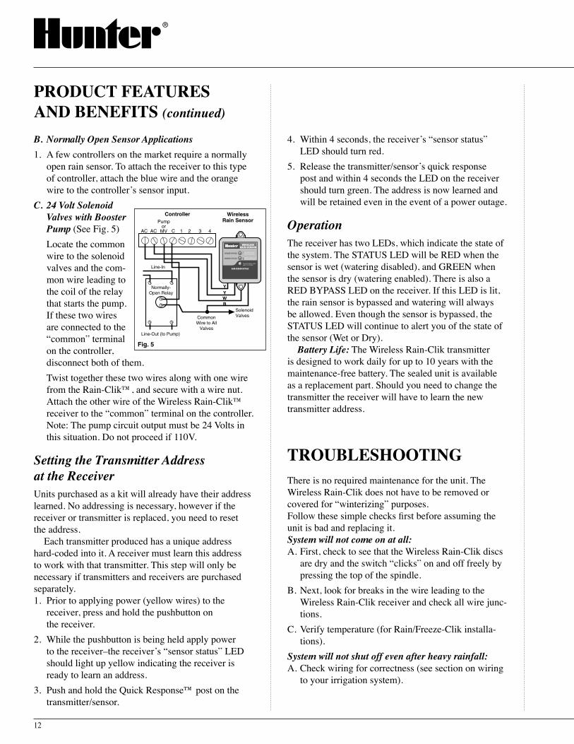
B. Normally Open Sensor Applications1. A few controllers on the market require a normally
open rain sensor. To attach the receiver to this type of controller, attach the blue wire and the orange wire to the controllerʼs sensor input.
C. 24 Volt Solenoid Valves with Booster Pump (See Fig. 5)
Locate the common wire to the solenoid valves and the com-mon wire leading to the coil of the relay that starts the pump. If these two wires are connected to the “common” terminal on the controller, disconnect both of them.
Twist together these two wires along with one wire from the Rain-Clik™, and secure with a wire nut. Attach the other wire of the Wireless Rain-Clik™ receiver to the “common” terminal on the controller. Note: The pump circuit output must be 24 Volts in this situation. Do not proceed if 110V.
Setting the Transmitter Address at the ReceiverUnits purchased as a kit will already have their address learned. No addressing is necessary, however if the receiver or transmitter is replaced, you need to reset the address.
Each transmitter produced has a unique address hard-coded into it. A receiver must learn this address to work with that transmitter. This step will only be necessary if transmitters and receivers are purchased separately. 1. Prior to applying power (yellow wires) to the
receiver, press and hold the pushbutton on the receiver.
2. While the pushbutton is being held apply power to the receiver–the receiverʼs “sensor status” LED should light up yellow indicating the receiver is ready to learn an address.
3. Push and hold the Quick Response™ post on the transmitter/sensor.
4. Within 4 seconds, the receiverʼs “sensor status” LED should turn red.
5. Release the transmitter/sensorʼs quick response post and within 4 seconds the LED on the receiver should turn green. The address is now learned and will be retained even in the event of a power outage.
OperationThe receiver has two LEDs, which indicate the state of the system. The STATUS LED will be RED when the sensor is wet (watering disabled), and GREEN when the sensor is dry (watering enabled). There is also a RED BYPASS LED on the receiver. If this LED is lit, the rain sensor is bypassed and watering will always be allowed. Even though the sensor is bypassed, the STATUS LED will continue to alert you of the state of the sensor (Wet or Dry).
Battery Life: The Wireless Rain-Clik transmitter is designed to work daily for up to 10 years with the maintenance-free battery. The sealed unit is available as a replacement part. Should you need to change the transmitter the receiver will have to learn the new transmitter address.
TROUBLESHOOTINGThere is no required maintenance for the unit. The Wireless Rain-Clik does not have to be removed or covered for “winterizing” purposes.Follow these simple checks first before assuming the unit is bad and replacing it.System will not come on at all:A. First, check to see that the Wireless Rain-Clik discs
are dry and the switch “clicks” on and off freely by pressing the top of the spindle.
B. Next, look for breaks in the wire leading to the Wireless Rain-Clik receiver and check all wire junc-tions.
C. Verify temperature (for Rain/Freeze-Clik installa-tions).
System will not shut off even after heavy rainfall:A. Check wiring for correctness (see section on wiring
to your irrigation system).
PRODUCT FEATURES AND BENEFITS (continued)

Manually depress the spindle atthe top of the Wireless Rain-Clik
Fig. 5
Fig. 6
Vent Ring
Vents
13
B. Is the rainfall actually hitting the Wireless Rain-Clik™? Check for obstructions to rainfall such as overhangs, trees or walls.
Adjustments and OperationOperation Check to Verify Correct WiringTurn on one zone of the irrigation system that is visible while you are in reach of the Rain-Clik™. Manually depress the spindle at the top of the Rain-Clik until you hear the switch "click" off (See Fig. 5). The sprin-kler zone should stop instantaneously. If it does not, check to see if is wired correctly. It is not necessary to “wet” test the Rain-Clik, although it is an optional way to test the operartion.
The Rain-Clik can keep the irrigation system from starting or continuing after rainfall. The time that it takes the Rain-Clik to reset for normal sprinkler opera-tion after the rain has stopped is determined by weather conditions (wind, sunlight, humidity, etc.) These condi-tions will determine how fast the hygroscopic discs dry out, and since the turf is also experiencing the same conditions, their respective drying rates will roughly parallel each other.
There is an adjustment capabil-ity on the Rain-Clik that will slow down the reset rate. By opening the “vent” (see Fig. 6) to completely or partially cover the ventilation slots, the hygroscopic discs will dry more slowly. This adjustment can com-pensate for an “overly sunny” instal-lation location, or peculiar soil conditions. Experience will best determine the ideal vent setting.
Bypassing The SensorThe Hunter ICC, Pro-C and SRC controllers are equipped with a built-in bypass that allows you to override an active sensor. For controllers not equipped with this feature, should you desire to bypass the operation of the Rain-Clik for any reason (i.e., turn on your system even though the Rain-Clik has shut “off” due to rainfall), there is a simple way to do this, add our Bypass Switch Box (Model #BPSW). This mounts
on or next to the controller, and by simply moving the switch, the Rain-Clik is bypassed.
MaintenanceThere is no required maintenance for the unit. The Rain-Clik does not have to be removed or covered for “winterizing” purposes.
MINI-CLIK® RAIN SENSORSimple, Accurate, Rugged and Reliable Rain SensorIn most installations, the Mini-Clik acts as a switch to break the circuit to the solenoid valves of the irrigation system when it has rained. This allows the timer to ad-vance as scheduled, but keeps the valves from activat-ing and allowing water to flow.
The Mini-Clik Rain Sensor automatically compen-sates for the amount of rainfall that occurred before reactivating. Hygoscopic discs absorb water and then expand proportionally to the amount of rain that fell. As the moisture-laden discs expand, they activate a switch that interrupts the electrical circuit from the controller to the valves. Once the Mini-Clik has dried sufficiently, the switch closes again to allow for normal operation. The time it takes the Mini-Clik to reset for normal sprinkler operation after the rain has stopped is determined by weather conditions such as sunlight, wind, humidity, etc. These conditions will determine how fast the discs dry out. The irrigated turf also ex-periences the same conditions. So when the turf needs more water, the Mini-Clik is already reset to allow the sprinkler system to go at the next scheduled cycle.
Wireless Rain-Clik™ / Mini-Clik® Sensor

1/8 1/41/2 3/41
14
Easily Installs on Any Automatic Irrigation System…Simple to add on to an existing or new installationThe Mini-Clik® is versatile enough to work with all popular irrigation controllers. The Mini-Clik is available in two versions. One is wired for “normally closed” sen-sor terminals and the other is wired for “normally open” sensor terminals. Each unit will have two wires attached to it, connected to a 25-foot extension.
Available in 24 Volt and 110/220 Volt UL Listed Models…Four different models to accommodate your particular wiring needsMini-Clik – The standard “normally closed” Mini-Clik model for use on most 24 Volt applications.Mini-Clik-NO – The standard “normally open” Mini-Clik model for use on most 24 Volt applications.Mini-Clik-C – Features a ½" female threaded inlet at the bottom to accommodate conduit.Mini-Clik-HV – The C model with added code approved liq-uid-tight electrical fittings for 110/220 Volt wiring applica-tions and systems using pumps drawing less than 10 amps peak. Also includes 18 inches of 16 AWG wire. Ready to mount on any standard junc-tion box.
Constructed of High Impact Thermoplastic…Dependable operation built to lastThe Mini-Clik is constructed of heavy-duty materials including a thermoplastic that can withstand all ex-tremes of weather from direct scorching sun to freezing ice storms.
Maintenance-Free Patented Sensing Mechanism…No callbacks, set it and forget itUnlike other rain sensors that use collection cups, the Mini-Clik does not collect debris, so it does not require cleaning. And, for those in cold climates, the Mini-Clik does not have to be removed or covered for “winteriz-ing” purposes. This means no required maintenance for the unit and no callbacks to clean it.
The sensing mechanism is in-genious but simple. Discs absorb water and then expand propor-tionally to the amount of rainfall that fell (e.g., a small cloudburst would result in little absorption, a thunderstorm with 2" of rainfall would lead to more absorption and thus more expansion). As the moisture-laden discs expand, they eventually activate a switch that interrupts the circuit from the controller to the valves. As the discs dry out, they contract and release the switch.
5-Year Warranty…Hunter Industries backs up its productsA full five-year warranty by Hunter communicates to our customers that the Mini-Clik is a rain sensor that stands up to the environment. The end-user can be as-sured of a quality product with a guarantee of depend-able operation.
Adjusts to Actuate at Various Rainfall Quantities…Versatile and accurateDepending on local conditions, the Mini-Clik can keep the irrigation system from starting or continuing after rainfall quantities of 1⁄8", ¼", ½", ¾", 1" (3 mm, 6 mm, 13 mm, 19 mm, 25 mm). To adjust it to the desired shutoff quantity, rotate the cap on the switch housing so that the pin are located in the proper slots.
PRODUCT FEATURES AND BENEFITS

15
Includes 25 Feet of 20 Gauge Two Conductor Wire…Fast and easy mounting out of sightHunter supplies wire needed for installation within 25 feet of the controller. Whether you pre-install on a pole or install at the job, with 25 feet of wire already attached to the Mini-Clik®, installation is fast and easy. When contractors go out to the job site with the Mini-Clik, they donʼt have to worry about forgetting the wire! If longer wire runs are needed for installation, no problem! Just add an extension.
If the extension needed is:25-50 feet use: 20 gauge50-100 feet use: 18 gauge100 feet or more use: 16 gauge
INSTALLATION INSTRUCTIONSIn most installations, the Mini-Clik acts as a switch to break the electrial circuit to the solenoid valves of the irrigation system when it has rained. This allows the timer to advance as scheduled, but keeps the valves from opening the water flow. Once the Mini-Clik has dried sufficiently, the switch closes again to allow for normal operation.
For the Model Mini-Clik-C: This rain sensor unit is the same as the standard model except for the lack of an aluminum mounting bracket and the addition of a ½" threaded cap, which allows for the easy use of electrical conduit to totally enclose the wires. Unless local code states otherwise, plumbing grade PVC pipe can be used as well as electrical grade conduit.For the Model Mini-Clik-HV: This rain sensor unit is designed to be used with automatic irrigation systems of two principle designs: 1) single-station electrical timer (e.g., Intermatic) that switches power to a pump, either directly or through a relay; or 2) single-station electrical timer that switches power to a solenoid valve.
MountingStandard Model: Using the screws provided, mount the Mini-Clik on any surface where it will be exposed to unobstructed rainfall, but not in the path of sprinkler spray. The switch-housing portion must be upright (as
pictured), but the swivel-bracket can be moved for mount-ing on any angled surface. Loosen the locknut and screw before swiveling bracket, and then re-tighten.
For the Conduit Model Mini-Clik-C: The conduit acts as the mounting support for the unit. Therefore, place and mount the conduit to allow for the desired sensor location as described in the main instructions for the standard model. Be sure to support the conduit sufficiently along its various lengths.
For the High-Voltage Model Mini-Clik-HV: The mounting of this unit is primarily made by screw-ing the fitting end into the threaded holes of covers to rectangular junction boxes (for outdoor use) or the covers of round junction boxes commonly used for outdoor spotlights. Locate the junction box so that with the Mini-Clik attached, unobstructed rainfall will hit the outermost sensing end of the unit. If a longer reach is needed, the “Carlon” flexible conduit piece can be substituted with a slightly longer piece (up to 8" length with no support or up to 11" with support).
Helpful hints for mounting:A. When looking for a suitable location such as on the
side of a building or post, the closer the Mini-Clik is to the controller, the shorter the wire run will be. This will also minimize the chance for wire breaks.
B. The ideal location for mounting is not always the most practical location. In the case where a compro-mise must exist (such as low location on a side wall rather than the preferred high location), note that the Mini-Clik will still work as it will always receive some rainfall – it just will not be as accurate in its gauging as it could be.
Mini-Clik® Sensor

1 2 3 4
Mini-Clik ControllerC
SolenoidValves
Common Wire toAll Valves
Fig. 3
Mini-Clik Pro-C or Hunter ICC
SEN
SEN
C
TEST
P MV
Fig. 2
16
C. As described in the “Operation” section of this manual, “reset rate” refers to the amount of time it takes the Mini-Clik® to dry out sufficiently for the sprinkler system to be allowed to come back on. The mounting location will affect this rate and should be taken into consideration should extreme conditions exist. For example, mounting the Mini-Clik on a very sunny, southern end of a building may cause the Mini-Clik to dry out sooner than desired. Similarly, mounting on the northern end of a building with constant shade may keep the Mini-Clik from drying soon enough.
Once the Mini-Clik is mounted, run the wire to the controller, and fasten it every few feet with wire clips or staples for best results. If an extension to the wire provided is needed, use the following table to deter-mine the minimum wire gauge needed:
If the extension needed is:25-50 feet use: 20 gauge50-100 feet use: 18 gauge100 feet or more use: 16 gauge
Wiring To Your Irrigation SystemImportant: The Standard Model Mini-Clik is sold and designed for hook up to 24 Volt irrigation controllers only. For wiring to 110V or 220V irrigation controllers, please consult your distributor or Hunter Industries Data Line at 800-733-2823. All wiring must conform to National Electrical Code or applicable local codes.
For the Model Mini-Clik-C: WARNING! This unit is designed to be installed in conjunction with 24VAC circuits only. Do not use with 110 or 220VAC circuits.
For the Model Mini-Clik-HV: WARNING! This unit must be installed by a qualified electrician in accor-dance with National Electrical Code and applicable local codes. The electrical rating of this device is 125-250VAC at 10.1 amps. Do not let current pass through this device that exceeds this rating. Do not install directly in line with any pump.
Wiring to the Hunter SRC ControllerThe Mini-Clik connects directly to the SRC. This allows you to easily override the sensor by using the RUN (BYPASS SENSOR) position on the dial.1. Route the wires from the Mini-Clik up through the
same opening used for valve wiring.2. Connect one wire to the RS terminal and other to
the C terminal (See Fig. 1).3. Connect the valve common to the RS terminal.
1 2 3 4
Mini-Clik
Hunter SRC
CRS
Connect Common tothis Terminal whenusing Rain Sensor
Connect RainSensor Wires toThese Two Terminals
SolenoidValves
Fig. 1
Wiring to the Hunter ICC, Pro-C or EC Controller The Mini-Clik connects directly to the EC, ICC or Pro-C. This allows you to easily override the sensor by using the Sensor switch on the front panel.1. Remove the jumper from the two “SEN” terminals.2. Route the wires from the rain sensor up through the
same conduit opening used for valve wiring.3. Connect one wire
to the terminal labeled “SEN” and the other wire to the other “SEN” terminal (See Fig. 2).
Other ControllersThe two most common situations are shown below. For non-standard wiring situations, please consult your distributor or request our “non-standard” wiring infor-mation packet.A. 24 Volt Solenoid
Valves Only (No booster pump) (See Fig. 3).
With the two wires from the Mini-Clik at the controller, locate the “common ground” wire of the solenoid valves. If it is connected to the com-mon terminal on the controller, disconnect it. Attach one wire of the Mini-Clik to the “common” terminal
INSTALLATION INSTRUCTIONS (continued)

Normally-Open Relay
1 2 3 4
Controller
C
SolenoidValvesCommon
Wire to AllValves
Mini-ClikPumpor MV
Line-In
Line-Out (to Pump)
Fig. 4
Controller
110VSoleniodValves
110VInput
110VSwitched
Input
110V Line
Mini-Clik-HV
Fig. 5
ControllerSwitchedOutputInput
Mini-Clik-HV
220V to Pump
Normally-Open Relay
Line-In
Coil
Fig. 6
1/8 1/41/2 3/41
VentVent Ring
Fig. 7
17
(usually marked “C”) on the controller. Attach the other wire of the Mini-Clik® to the common wire leading to the valves. Note: The common wire to the valves does not have to be interrupted at the controller. The Mini-Clik may be wired anywhere along the common wire line.
B. 24 Volt Sole-noid Valves with Booster Pump (See Fig. 4)
Locate the com-mon wire to the solenoid valves and the common wire leading to the coil of the relay that starts the pump. If these two wires are connected to the “com-mon” terminal on the controller, disconnect both of them.
Twist together these two wires along with one wire from the Mini-Clik, and secure with a wire nut. Attach the other wire of the Mini-Clik to the “com-mon” terminal on the controller. Note: The pump circuit output must be 24 Volts in this situation. Do not proceed if 110V.
C. Special In-structions for Mini-Clik-HV (See Fig. 5 and 6)
The two taped and stripped wires are the ones to be used when follow-ing these accom-panying diagrams. All wire connec-tions with the Mini-Clik should be made with wire nuts and located in a junction box.
Where the timer is controlling a pump, the relay may be inside the timer, external,
or non-existent. If there is no relay in the circuit, one must be added. The wiring for an internal or external relay is the same: The Mini-Clik breaks the circuit to the coil of the relay only. Either wire of the coil may be broken.
Operation Check to Verify Correct WiringTurn on one zone of the irrigation system that is vis-ible while you are in reach of the Mini-Clik. Manually depress the spindle at the top of the Mini-Clik until you hear the switch “click” off. The sprinkler zone should stop instantaneously. If it does not, check to see if it is wired correctly.
Adjustments and OperationThe Mini-Clik can keep the irriga-tion system from starting or continu-ing after rainfall quantities of 1⁄8", ¼", ½", ¾" or 1". To adjust it to the desired shut-off quantity, rotate the cap on the switch housing so that the pins are located in the proper slots (see Fig. 7). Do not forcibly twist the cap as this might break the pin.
The time that it takes the Mini-Clik to reset for normal sprinkler operation after the rain has stopped is determined by weather conditions (wind, sunlight, humidity, etc.) These conditions will determine how fast the hygroscopic discs dry out, and since the turf is also experiencing the same conditions, their respective drying rates will roughly parallel each other. So when the turf needs more water, the Mini-Clik is already reset to allow the sprinkler system to go at the next scheduled cycle.
There is an adjustment capability on the Mini-Clik that will slow down the reset rate. By turning the “vent ring” (see Fig. 7) to completely or partially cover the ventilation holes, the hygoscopic discs will dry more slowly. This adjustment can compensate for an “overly sunny” installation location, or peculiar soil conditions. Experience will best determine the ideal vent setting.
Mini-Clik® Sensor

18
System will not come on at all:A. Make sure the Mini-Clik® is not installed in the path
of any watering from the systemʼs sprinklers.B. Check to see that the Mini-Clik discs are dry and
the switch “clicks” on and off freely by pressing the top of the spindle.
C. Look for breaks in the wire leading to the Mini-Clik and check all wire connections.
System will not shut off even after heavy rainfall:A. If a Hunter SRC controller is used, check the dial
position. If the dial is on the RUN (Bypass Sensor) position the controller will disregard sensor. For the Pro-C and ICC, make sure the Bypass Switch is in "Active."
B. Check Bypass Switch position. If the switch is on the BYPASS position on the controller or external by-pass switch (Hunter BPSW) the controller will disregard sensor activity.
C. Check to see if wiring is correct. Check by depress-ing the spindle at the top of the cap until the switch is heard “clicking” off. When the switch “clicks” off, the sprinkler zone should stop immediately.
D. Check the sensitivity setting on the Mini-Clik. If the setting is set for high rainfall amounts, move the cap to a more sensi-tive setting.
E. Is rainfall actually hitting the Mini-Clik? Check for obstruc-tions to rainfall such as over-hangs, tree branches or walls.
FREQUENTLY ASKED QUESTIONSQ: Two days ago it rained and the sprinklers came on
this morning, how do I get them to stay off longer?A: There is a “vent ring” located just below the cap
that can be closed or partially closed to restrict airflow through the Mini-Clik. Make sure this ring covers the holes on the Mini-Clik, and it will al-low the discs to dry more slowly, thus keeping the
Mini-Clik shut off longer. This adjustment can com-pensate for an “overly sunny” installation location.
Q: How much water and money can be saved?A: The amount saved varies, but in a temperate climate
with average rainfall, savings are usually substan-tial. There are several factors involved in determin-ing how much a Mini-Clik can reduce water usage: how often it rains, whether or not the controller is left on for automatic operation, and the amount of water applied by the system per cycle.
Basically, if you know the water costs in your area and how much water is being applied per watering cycle by the whole system, then you will know how much is being saved each time the Mini-Clik inter-rupts the sprinkling cycle because of rainfall.
As an example, take a system that irrigates 15,000 square feet of turf and is set to run each zone so that the equivalent of ¼" of water is applied per cycle. Volumetric calculations determine that 2337 gallons of water are being applied over the 15,000 square feet of turf per cycle. Using an average water cost table for the San Marcos, California area, it costs $3.47/thousand gallons (or, for our example, $8.11 for the 2337 gallons). Therefore, every time the Mini-Clik prevents the sprinkling cycle from proceeding because of rainfall, $8.11 is saved, and 2337 gallons of fresh water are not wasted. Multiply this by the number of substantial rainfalls that occur in your area over one growing season and you can see the potential for savings of money and water. The Mini-Clik pays for itself in a short time, and the installed irrigation system is the most efficient it can be.
S P E C I F I C A T I O N G U I D E
EXAMPLE: MINI-CLIK - HV
MODELMINI-CLIK
OPTIONSHV = High Voltage Model for 110/220VAC ApplicationsC = Conduit MountNO = Normally Open Switch
Note: For Mini-Clik® in Sensor Guard enclosure, specify SG-MC. To add Bypass Switch Box to any non-Hunter controller installation, specify BPSW with sensor. Bypass switch function is standard in all Hunter controllers.
TROUBLESHOOTING

19
Item Description Catalog No.
1 Cap and Spindle Assembly 440200
2 Vent Ring 440100
3 Switch Housing 440000
4 Switch 206431
5 Bracket 439700
6 Inside Housing Bracket Screw 194986
7 Outside Housing Bracket Screw 201532
8 Housing Bracket Locknut Set (2) 206498
Note: Part numbers 1 through 4 are common to Mini-Clik and Mini-Clik-C.
5
4
3
2
1/8 1/41/2 3/41
1
6
7
8
Control Irrigation System Operation During High WindsThe Wind-Clik Wind Sensor acts as a switch to break the circuit to the solenoid valves of the irrigation system during windy conditions. This allows the timer to advance as scheduled, but stops the valves from activating (not allowing water to flow). Once the wind conditions drop below the reset point, the switch closes again to allow for normal operation. The Wind-Clik can be used in conjunction with other sensors to en-hance the overall automation of any irrigation system. Mount the unit in an area that receives prevailing winds without hindrance.
PRODUCT FEATURES AND BENEFITS
Installs Simply and Easily…No adjustments necessaryThe Wind-Clik is designed to install directly to a “normally closed” or “normally open” controller s̓ sensor terminals or in the common wire circuit between the zone valves and the controller. If multiple commons are used in the system, the Wind-Clik must be tied in to the end of all the common wires, then connected to the controller. If the Mini-Clik® or Freeze-Clik® is already installed or is to be part of the system, the wind sensor is to be wired in series with the other sensors so either or both devices can control the circuit.
Designed for “Normally Closed” or “Normally Open” Operation…Versatile to meet the needs of all controllersThe type of controller used on the job will not be a concern for the installer because the Wind-Clik is designed to work with either “normally closed” or “normally open” sensor circuits. The unit comes from Hunter with three colored wires attached ready for installation. Depending on what the controller sensor circuitry is, the installer will hook up the green and red wires for “normally closed” and hook up the green and blue wires for “normally open” systems.
REPLACEMENT PARTS WIND-CLIK® WIND SENSOR
Mini-Clik® / Wind-Clik® Sensor

20
Adjustable Shutoff for Wind Speeds Between 12 and 35 mph…Effectively control irrigation system operation during windy conditionsA simple turn of the side ad-justment on the side of the Wind-Clik® allows the ir-rigation system to shut down between wind speeds of 12 and 35 mph. Wind speeds often vary according to ground height, so for irrigation system control, the wind speed about 6 feet above the ground would be a good representative height for the Wind-Clik placement.
Automatic Reset of System at Wind Speeds from 8 to 24 mph…Select the setting that is best for your areaA feature just as important as a shutoff speed is the reset speed. This is the speed that the wind will have to slow down to in order to reset the switch. The Wind-Clik allows the user to adjust a reset speed be-tween 8 and 24 mph with a turn of the side adjustment.
Automatic Damping Feature…Eliminates erratic system operation due to gusty windsThe built-in damping feature allows for short wind gusts to occur without affecting the performance of the system, thus keeping the system from repetitively cycling on and off. Therefore, the wind speed settings, while accurate under controlled conditions, are actually relative averages when set up in the field.
Reduces Liability Hazards of Wet Walkways and Roadways…Wind-blown water will no longer be a safety concernToday, with litigation a prominent factor in how business is con-ducted, reducing liability hazards of wet sidewalks and roadways in our landscapes is something Hunter takes seriously. With the Wind-Clik installed in the system, wind blown water is not an issue.
Cut Down on Overspray When Used with Fountains…Keep surrounding areas safe and dryA common non-irrigation related installation of the Wind-Clik is utilizing the product with fountain sys-tems. With a quick adjustment of the dial water can be stopped from blowing outside the fountain contain-ment area.
5-Year Warranty…Hunter Industries backs up its productsA full five-year warranty by Hunter communicates to our customers that the Wind-Clik is a device that stands up to the environment. The end-user can be assured of a quality product with a guarantee of dependable operation.
S P E C I F I C A T I O N G U I D E
EXAMPLE: WIND-CLIK
MODELWIND-CLIK
Note: To add Bypass Switch Box to any non-Hunter controller installation, specify BPSW with sensor. Bypass switch function is standard in all Hunter controllers.
FREEZE-CLIK® FREEZE SENSOR
Control Irrigation System Operation During Freezing TemperaturesIn most installations, the Freeze-Clik® Sensor acts as a switch to break the circuit to the solenoid valves of the irrigation system near freezing. This allows the timer to advance as scheduled, but stops the valves from activating not allowing water to flow. Once the low temperature period climbs above 37°F (3°C), the switch closes again to allow for normal operation.
PRODUCT FEATURES AND BENEFITS (continued)

21
Installs Simply and Easily…No adjustments necessaryThe Freeze-Clik® is designed to install directly to a “normally closed” controllerʼs sensor terminals or in the common wire circuit between the zone valves and the controller with two-conductor wire. No adjustments are necessary. If multiple commons are used in the sys-tem, the Freeze-Clik must be tied in to the terminus of all the common wires, then connected to the controller.
Available in 24 Volt Standard and Reverse Switching Models…Two different models to accommodate your particular wiring needsFreeze-Clik – The standard Freeze-Clik model for use on most 24 volt applications.Freeze-Clik-Rev – This model designed for opposite switching designed to turn a device on when tem-peratures approach freezing (example: to protect vegetation from a damaging freeze).Note: The Freeze-Clik is not designed for crop protection
Accurate Shutoff Before Water Turns to Ice…Reduces liability hazards for walkways and roadways by preventing icingAccurate, epoxy sealed temperature-sensing element automatically stops system water flow at near freez-ing temperatures and resets system when temperatures rises above the set point of 37°F (3°C) (+/- 2°C).
Reduces Liability Hazards of Iced Walkways and Roadways…“Wayward” water that freezes over is never a safety issueWater from irrigation systems that lands on pavement and freezes over can create serious liability hazards. Reducing or eliminating this concern is important to any irrigation installer. With the Freeze-Clik installed in the system, running water that freezes on traffic areas is not an issue.
Includes 25 Feet of 20 Gauge Two Conductor Wire…Fast and easy mounting out of sightHunter supplies wire needed for installation within
25 feet of the controller. When contractors go out to the job site with the Freeze-Clik, they donʼt have to worry about forgetting the wire, making the installation fast and easy! If longer wire runs are needed for installa-tion, no problem! Just add an extension If the extension needed is:25-50 feet use: 20 gauge50-100 feet use: 18 gauge100 feet or more use: 16 gauge
Can be Used in Conjunction With Other Sensors…Enhances the overall automation of irrigation systemsIf the Mini-Clik® or Wind-Clik® is already installed or is to be part of the system, the Freeze-Clik is to be wired in series with the other sensors so either or both devices can control the circuit.
5-Year Warranty…Hunter Industries backs up its productsA full five-year warranty by Hunter communicates to our customers that the Freeze-Clik is an irrigation sensor that stands up to the environment. The end-user can be assured of a quality product with a guarantee of dependable operation.
INSTALLATION INSTRUCTIONSNote: Both the standard Freeze-Clik and the Freeze-Clik-
Rev (a “reverse” model where instead of switching system operation “off” at a set temperature point, the system is switched “on”) are installed and wired in the same manner.
The correct placement of the Freeze-Clik is critical for accurate temperature sensing. It must be mounted out of direct sunlight, and where free outdoor air circulation is possible. Examples would be the north wall of a building or under eaves or overhangs.
PRODUCT FEATURES AND BENEFITS
Wind-Clik® / Freeze-Clik® Sensor

Fig. 1
1 2 3 4
Freeze-Clik®
Hunter SRC Controller
CRS
Connect Common tothis Terminal whenusing Rain Sensor
Connect RainSensor Wires toThese Two Terminals
SolenoidValves
Fig. 2
Freeze-Clik®
Hunter ICCHunter Pro-C
Controller
SEN
SEN
C
TEST
P MV
Fig. 3
To SolenoidValves
Mini-Clik®
Freeze-Clik®
1 2 3 4
Controller
C
Common WireFig. 5
1 2 3 4
Freeze-Clik® Controller
C
Common Wire toAll Valves
To SolenoidValves
Fig. 4
22
If the best location for temperature sens-ing is not a feasible location for mounting the Freeze-Clik®, an al-ternate location may be chosen if, in addition, a “sun guard” is used (a piece of flashing, for example) to shade the Freeze-Clik during that time of day that the sun could hit it (see Fig. 1).
The Freeze-Clik housing is designed so that it provides the sensing element some amount of shaded protection from direct or indirect radiation, while al-lowing air to move freely around it. Using the screws provided, attach the Freeze-Clik to the chosen surface. Run the extension wire to the controller.
Wiring
Wiring to the Hunter SRC ControllerThe Freeze-Clik connects directly to the SRC. This allows you to easily override the sensor by using the RUN (BYPASS SENSOR) position on the dial.1. Route the
wires from the Freeze Clik up through the same opening used for valve wiring.
2. Connect one wire to the RS termi-nal and other to the C terminal (See Fig. 2).
3. Connect the valve common to the RS terminal.
Wiring to the Hunter ICC, Pro-C and EC ControllerThe Freeze-Clik connects directly to the ICC, Pro-C and EC. This allows you to easily override the sensor by using the Sensor switch on the front panel.1. Remove the jumper from the two “SEN” terminals.2. Route the wires from the rain sensor up through the
same conduit opening used for valve wiring.
3. Connect one wire to the terminal labeled “SEN” and the other wire to the other “SEN” terminal (See Fig. 3).
Other ControllersThe Freeze-Clik freeze sensor is wired to the 24 VAC com-mon ground circuit of the solenoid valves (as shown in Fig. 4). Locate the common ground wire of the solenoid valves. If it is connected to the common terminal on the controller, discon-nect it.
Attach one lead of the Freeze-Clik to the common terminal on the controller and the other lead to the com-mon ground wire of the solenoid valves.
If a Mini-Clik® rain sensor is already installed or is to be part of the installation (see Fig. 5), the freeze sensor is to be wired in series with the rain sensor so that either (or both) devices can control the circuit.
OperationThe Freeze-Clik is preset and is not adjustable. It will break the common ground circuit, thereby keeping the sprinkler system from operating at, or below, 3˚C (37˚F). At temperatures above 3˚C, it will close the circuit for normal sprinkler operation.
Freeze-Clik-Rev Model: The temperature setting works in reverse on this model with the circuit not allowing operation of the sprinkler system above 3˚C (37˚F). Once the temperature reaches this point or goes below, it will activate the system and commence water-
INSTALLATION INSTRUCTIONS (continued)

23
ing for whatever amount of time you have set on your controller.Special usage note: For landscape applications only. Not
for crop protection. A freeze sensor should only be used as part of a sound irrigation management program, including regular system visual checks.
Bypassing the Freeze-Clik®
The Hunter ICC, Pro-C and SRC controllers are equipped with a built-in bypass that allows you to override an active sensor. For controllers not equipped with this feature, should you desire to bypass the operation of the Freeze-Clik for any reason (i.e., turn on your system even though the Freeze-Clik has shut “off” due to low temperature), add our Bypass Switch Box to the controller. By simply moving the switch, the Freeze-Clik is bypassed.
S P E C I F I C A T I O N G U I D E
EXAMPLE: FREEZE-CLIK - REV
MODELFREEZE-CLIK
OPTIONREV = Reverse Switching
Note: To add Bypass Switch Box to any non-Hunter controller installation, specify BPSW with sensor. Bypass switch function is standard in all Hunter controllers.
Each of Hunter s̓ Three Sensors in One Convenient UnitA must for commercial and municipal sites, but certainly a great investment for any site that requires more than one sen-sor. The Mini-Weather Station-which includes the Mini-Clik®, Freeze-Clik, and Wind-Clik® in one convenient package-will save water and money, paying for itself within a short time. A tremendous benefit of this station is the ease in which it is installed, with a variety of mounting options and just two wires attaching to the controllerʼs sensor or common wire terminal connections.
PRODUCT FEATURES AND BENEFITS
Easy to Install on Any Automatic Irrigation System…Versatile enough to meet your particular needsThe Mini-Weather Station is designed to install directly to a “normally closed” controller s̓ sensor terminals or in the common wire circuit between the zone valves and the controller. If multiple commons are used in the system, the Mini-Weather Station must be tied in to the terminus of all the common wires then connected to the controller.
Two Different Models to Accommodate Your Weather Sensing Needs…Available with or without a Freeze SensorMWS – Weather Station combines wind and rain sen-sors for use on 24 volt applications.MWS-FR – Weather Station incorporates rain, wind and freeze sensors for use on 24 volt applications.
Heavy Duty Construction…Built sturdy for years of trouble-free operationThe Mini-Weather Station is molded from schedule 40 PVC plastic parts with a 2" inlet. The inlet is designed to slip over a standard piece of 2" PVC pipe (2.375", 60.4 mm O.D.). The inlet can be reduced in size using a common PVC slip bushing if needed.
MINI-WEATHER STATION
Freeze-Clik® / Mini-Weather Station Sensor
WEATHER SENSORBYPASS SWITCH
ACTIVE
BYPASS
Rain, Windor FreezeSensor
ValveCommon
Controller
C P 1 2 3 4 5
24 VAC C UL LISTED 7F19
Fig. 1
Fig. 2
24
Shuts System off in Rainy Conditions…Sets from 1⁄8" to 1" based on local conditionsDepending on local conditions, the Mini-Weather Station can keep the irrigation system from starting or continuing after rainfall quantities of 1⁄8", ¼", ½", ¾", 1" (3 mm, 6 mm, 13 mm, 19 mm, 25 mm).
Sets to Shut Down System from 12 to 35 mph Winds…Adjusts to actuate at various wind speedsA simple turn of the side adjustment knob on the Mini-Weather Station allows the irrigation system to shut down between wind speeds of 12 and 35 mph. Wind speeds often vary according to ground height, so for irrigation system control, the wind speed about 6 feet above the ground would be a good representative height for the Mini-Weather Station placement.
Automatically Shuts Off Water at 37°F (3°C)…Eliminates ice on landscapes, walkways, and roadwaysAccurate, epoxy sealed temperature-sensing element automatically stops system water flow at near freez-ing temperatures and resets system when temperatures rises above the set point of 37°F (3°C) (+/- 2°F).
5-Year Warranty…Hunter Industries backs up the productsA full five-year warranty by Hunter communicates to our customers that the Mini-Weather Station stands up to the environment. The end-user can be assured of a quality product with a guarantee of dependable operation.
S P E C I F I C A T I O N G U I D E
EXAMPLE: MWS - FR
MODELMWS = Wind and Rain Sensors
OPTIONSFR = Combines Wind, Rain and Freeze Sensors
Note: To add Bypass Switch Box to any non-Hunter controller installation, specify BPSW with sensor. Bypass switch function is standard in all Hunter controllers.
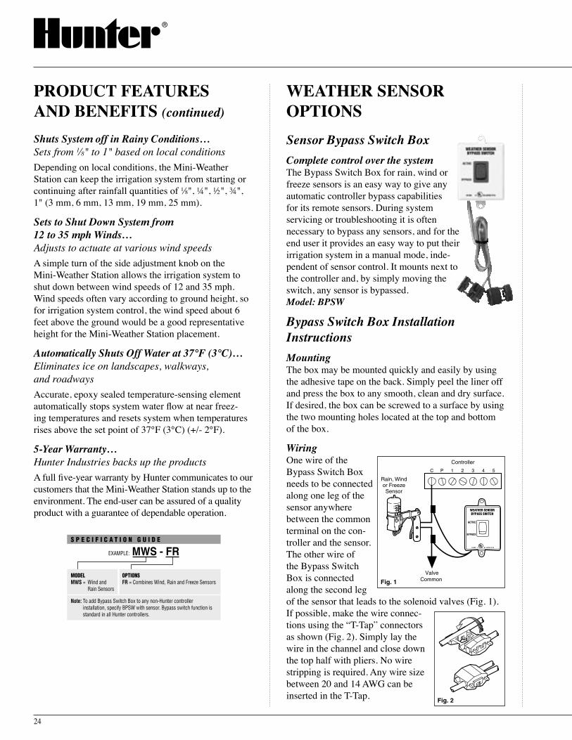
Sensor Bypass Switch BoxComplete control over the system The Bypass Switch Box for rain, wind or freeze sensors is an easy way to give any automatic controller bypass capabilities for its remote sensors. During system servicing or troubleshooting it is often necessary to bypass any sensors, and for the end user it provides an easy way to put their irrigation system in a manual mode, inde-pendent of sensor control. It mounts next to the controller and, by simply moving the switch, any sensor is bypassed.Model: BPSW
Bypass Switch Box Installation InstructionsMountingThe box may be mounted quickly and easily by using the adhesive tape on the back. Simply peel the liner off and press the box to any smooth, clean and dry surface. If desired, the box can be screwed to a surface by using the two mounting holes located at the top and bottom of the box.
WiringOne wire of the Bypass Switch Box needs to be connected along one leg of the sensor anywhere between the common terminal on the con-troller and the sensor. The other wire of the Bypass Switch Box is connected along the second leg of the sensor that leads to the solenoid valves (Fig. 1). If possible, make the wire connec-tions using the “T-Tap” connectors as shown (Fig. 2). Simply lay the wire in the channel and close down the top half with pliers. No wire stripping is required. Any wire size between 20 and 14 AWG can be inserted in the T-Tap.
WEATHER SENSOR OPTIONS
PRODUCT FEATURES AND BENEFITS (continued)

25
OperationPut the Bypass Switch in the “Auto” position for normal sensor control of the system. Putting the switch in “Bypass” position closes the circuit to the solenoid valves independent of the rain sensor switching.
Sensor GuardVandal resistance and rain sensor all-in-oneCombining the reliability of a Mini-Clik® rain sensor with the security of a compact vandal resistant enclo-sure, the Sensor Guard is perfect for sports facilities, golf courses and municipal sites. Easy to install, the Sensor Guard includes a Mini-Clik conduit rain sensor plus stainless steel mounting bolts and a drill tem-plate. A great way to keeps hands off the Mini-Clik when mounting the unit on pedestal controllers or controller enclosures.Model: SG-MC
FLOW-CLIK™ FLOW SENSOR
Affordable, Rugged and Reliable Flow Monitoring SystemShutting down an irrigation system when excess flow occurs provides the benefits of reduced liability, water conservation, erosion prevention and an overall reduction in repair costs. Typical causes for over-flow conditions can stem from problems due to ruptures in the main or lateral lines, when heads are broken or removed from the system, or valves do not shut off au-tomatically. Until now, installing a flow sensing device as an integral part of the irrigation system on many sites was cost prohibitive due to the relatively high cost of the flow sensing device itself as well as the Central Control system needed to monitor them.
The new Hunter Flow-Clik®, is a sophisticated flow sensor that monitors flow to an irrigation system. In the case of an overflow condition, the Flow-Clik will automatically shut down the irrigation system.
The Flow-Clik acts as a switch to break the electri-cal circuit to the solenoid valves as soon as it registers
a flow exceeding a calibrated set limit. This allows the timer to advance as scheduled, but keeps the valve(s) with a “high flow” from activating.
As a result of installing the flow sensor in a system, a user gains the benefit of substantially reducing the amount of water loss during an occurrence of an over-flow situation.
PRODUCT FEATURES AND BENEFITS
Low Cost…An extremely reliable and accurate flow sensor for any system budgetUnlike other flow-sensing devices by other manu-facturers and the central control systems needed to receive the benefits of monitoring flow are very costly, the relative low cost of the Hunter Flow-Clik fits into any site's budget. At a fraction of the cost, the Hunter Flow-Clik provides the many benefits associated with monitoring flow. It will work with all Hunter control-lers as well as many other manufacturer controllers. The Flow-Clik is the perfect choice for any contractor or property owner who is interested in monitoring flow to reduce their exposure to liability, reduce repair costs and conserve water.
Liability Reduction…Minimize the possibility of litigation from unforeseen system breaksToday, the reality of lawsuits is a real concern to in-stallers and property owners alike. They cannot ignore any hazardous situation that can be easily prevented, including an event such as an irrigation system that has excess flow due to a ruptured mainline pipe or a dam-aged sprinkler head. This excess water flow may cause flooding onto an area that can pose a danger of injury to the public making the risks of a potential lawsuit very real. The costs associated with this potential li-ability can be huge. Installing a Hunter Flow-Clik™ as an insurance policy will pay dividends in dollars and “peace-of-mind”.
MWS / Options / Flow-Clik™ Sensor

26
Sophisticated Water Conservation…Automatic high-flow shutoff feature saves water and moneyWe all know that water is not free! We either pay for it directly or we pay for the pump electricity costs. So whenever a high flow situation occurs due to a ruptured pipe or damaged sprinkler head, all that extra water going through the break onto areas that are not benefit-ing from the extra water is running up the bill. If the system continues to operate in a “high-flow” state, the potential incremental cost of water can be substantial.
Erosion Prevention…Stop major landscape damage before it startsThe erosion damage that can come from a ruptured pipe or sprinkler break can be very substantial. Just imagine a 2" mainline in a landscaped area of a local park rupturing on a Sunday at 2:00 AM. By the time the city worker gets to the site to shut down the system, an enormous amount of water will have flowed onto the park and adjacent properties causing severe erosion damage. In this scenario, with a Hunter Flow-Clik monitoring system flow, a “high flow” situation would have been diagnosed and the entire irrigation system would be shut down instantly if installed on the main-line leading to all of the individual control valves.
Reduced Costs for Rupture Related Repairs…Unanticipated budget allocations kept to a minimumWhen a Flow-Clik is installed in the mainline pipe near the point of connection to the site water supply and ad-jacent to a master valve, it will provide the ultimate in protection from damage caused by excess water flow. With the Hunter Flow-Clik flow sensor monitoring the systems flow, if a pipe ruptures, repairs would be minimal because of the quick shutdown response that the flow sensor provides.
Interface Panel Provides Control System Compatibility…An overflow watchdog providing a constant update of flow for any systemThe Hunter Flow Sensor Interface Box allows the Hunter Flow-Clik to function with all of the Hunter controllers and makes the Flow-Clik compatible with just about any other irrigation controllers on the market
today. With the interface box attached to the control-ler, the Flow-Clik will keep an eye on any system as it watches for “high-flow” conditions.
The controller provides the power for the interface panel to operate allowing it to send signals continu-ously directly to the controller telling it to shut down or start up based on flow conditions. Also, the inter-face keeps the system operator aware and informed as to what is happening out in the system. A multicolor LED located on the interface displays the status of the system.
The Flow-Clik Interface Box has a System Status indicator LED that provides information on the current status of the Flow-Clik system.• GREEN indicates power is applied to the sensor,
but no flow is occurring.• FLASHING GREEN indicates an acceptable
amount of water is flowing. (Below the flow sensor calibrated maximum)
• FLASHING RED indicates that overflow is occurring (Water flow in excess of the calibrated maximum)
• RED indicates an unacceptable amount of water was flowing and the system has been shut down. (Water flow exceeded the calibrated maximum for a period longer than the startup delay).
• ALTERNATING RED/GREEN indicates that system overflow occurred during the last automatic watering cycle (press the Restart/Calibrate button to reset the system status indicator.
• YELLOW indicates that the Flow-Clik calibrating the sensor to the system flow).
Designed to Meet the Needs of Commercial and Residential Piping Systems…The new Hunter Flow-Clik sensor bodies are avail-able with an inlet/outlet sizes from 1" to 4" that will measure water flow from a minimum of 6 GPM to a maximum of 400 GPM.
Installs Easily in New or Existing Systems…Simple to add on to a new or existing installationThe Flow-Clik™ can be installed simply and easily to any standard 24-volt irrigation control system. Simply install the unit into the irrigation mainline. The wire
PRODUCT FEATURES AND BENEFITS (continued)

27
that is attached to the unit then is connected to wire routed back to the Sensor Interface Box. With an easy installation procedure, the Hunter Flow-Clik will start to pay dividends almost immediately.
Install Flow-Clik Sensor up to 1000' from the Controller…At times the ideal placement for a flow-sensing device is a long distance from the controller location. An advantage of the Hunter Flow-Clik is that it can be installed up to a maximum distance of 1000 feet from the interface when installed with #18 gauge or larger copper wire. This gives the installer the added flexibility of installing the flow sensor in a location that will pro-vide maximum benefit in monitoring system flow.
Programmable Start-up Delay…Increased start-up flow velocities won t̓ effect flow sensor readingsThe high velocities that are common during the initial activation of an irrigation cycle could cause the flow sensor to sense a “high flow” situation and subsequent-ly shut down the irrigation system at the beginning of every cycle. The Flow-Clik addresses this potential issue by giving the user the capability to select one of nine preset start-up delays ranging from 20 to 300 seconds to provide adequate time for the system flow and velocity to stabilize.
Programmable Automatic System Reset…System monitoring without interventionThe Flow-Clik has the capability of diagnosing a high-flow condition, shutting down the system or individual zone, then automatically starting up the system again after a pre-selected time has passed. By waiting out a selected amount of time allows the controller to bypass the “problem” zone and continue watering the “good” zones.
The Hunter interface offers pre-selected off times that are user programmable by a dial with seven pre-se-lected positions. Using the Flow-Clik allows the prop-erty to continue to be automatically irrigated through the other zones without any user intervention.
With other flow sensors on the market today, if a
pipe was to rupture or sprinklers were dam-aged creating a “high-flow” situation, the system would shut down and stay down until the flow sensor was manually reset. If the irrigation manager were not available to reset the flow sensor, the watering schedule would be completely eliminated.
Customized Calibration for Precise System Control…Every irrigation system is set individuallyUsing the Flow-Clikʼs interface, the sensor is calibrated with the simple push of a button during the operation of the highest flow zone. While the system is “learn-ing” the flow, a yellow LED light is visible indicating the status to the user.
For a more accurate determination of the total flow for each zone, it is recommended that you measure the nozzle pressure at each sprinkler zone and then look up the nozzle flow at that specific pressure in the nozzle performance data section of the manufacturer product catalog. Note: A guideline that will help you easily determine
which valve zone has the highest flow (GPM), is to count the number of sprinklers on the zone and multiply each spray head by 2.0 GPM, each me-dium range rotor by 4.0 GPM and each large range rotors by 15.0 GPM.
5-Year Warranty…Hunter Industries backs up its productsA full five-year warranty by Hunter communicates to our customers that the Mini-Clik® is a rain sensor that stands up to the environment. The end-user can be as-sured of a quality product with a guarantee of depend-able operation.
Flow-Clik™ Sensor

Valve 4 (18.9 GPM) Valve 5 (16.0 GPM)
ICC Controller
®
®®
®
®
®
®
®
Flow-Clik Sensor
Master Valve
Back Flow Preventer
Point of Connection
WireMainline Pipe
Valve 6(17.0 GPM)
Valve 1 (13.0 GPM) Valve 7 (16.0 GPM)
Valve 2(14.0 GPM)
Valve 3(15.0 GPM)
Flow-Clik Interface
Valve 4 has been determinedto have the highest flow
Flow-Clik is located on mainlineto shut down the system if the mainline is ruptured
28
Flow-Clik™ System OverviewIllustrative ExampleIn this illustrative example of a small commercial site, the Flow-Clik sensor is connected to the mainline pipe that provides water to the system control valves. Because it is installed immediately down stream of the master valve, it will provide the added protection of shutting down the irrigation system if a mainline break should occur.
The Flow-Clik can be set to automatically shut off the system at a specified level of flow that is deter-mined by you and your specific systems needs. In this example, the valve that commands the highest flow is valve number 4, which has a total flow rate of 18.9 gal-lons per minute (GPM). The user will turn this valve on and then depress a button on the Flow-Clik Interface to calibrate the flow sensor to automatically identify any flow in excess of this pre-determined amount (approximately 10% above) to be a “high flow” condition. If flow exceeds 21.0 GPM, a signal would be sent to the Flow-Clik Interface which would communicate to the Controller to interrupt the system for a prescribed period of time.
The system interrupt period and the system start-up delay can be adjusted by moving the dial on the Flow-Clik Interface to a specific setting ranging from 2 to 60 minutes. In this particular example, the dial on the Flow-Clik Interface is set to a 10 minute System Interrupt Delay and another dial on the interface is set to a 20 second Start-up delay.
High-Flow Scenario 1 - Valve 3 Lateral Line BreaksIf a lateral line break should occur on valve number 3, the Flow-Clik would sense a “high-flow” condition (>21.0 GPM) and would shut down that specific zone (valve) for 10 minutes and then monitor the flow again in 10 minute intervals. When monitored flow is below 21.0 GPM, the scheduled irrigation cycle based on the controller program will resume.
If the run time for zone 3 is 19 minutes and is sched-uled to come on at 6:00AM, then the following chain of events would occur:
6:00 AM – Valve 3 is activated and after a 20 sec-ond delay a “high flow” condition is sensed by the Flow-Clik and the system is interrupted for 10 minutes.
6:10 AM – Valve 3 is re-activated and after a 20 second delay a “high-flow” condition is identified again and the system is interrupted for another 10 minutes.
6:18 AM – Valve 4 is scheduled to be activated but the Flow-Clik continues to interrupt system operation due to the 1 minute left on the System Interrupt Delay.
6:20 AM – Valve 4 is activated and after a 20 second delay the Flow-Clik monitors the flow of valve 4 which is below the “high flow” trigger point
FLOW-CLIK™ SYSTEM OVERVIEW

Minimum 5 x pipediameter from nearest
turn in system
Water FlowMAIN LINE OR LATERAL LINE
Minimum 10 x pipe diameter from nearest
turn in system
Fig. 1
Fig. 2
29
enabling the valve to continue to irrigate for its prescribed time.
Post 6:20 AM – For the balance of the day (provided that Zone 3 is not scheduled to operate again), flow is monitored by the Flow-Clik™ without exceed-ing the maximum and the total irrigation schedule is completed.
High Flow Scenario 2 - Mainline RupturesIf a mainline ruptures, the Flow-Clik would identify a “high-flow” condition approximately 20 seconds after the first valve is activated based on the irrigation sched-ule and the master valve would be shut down. Flow would continue to be monitored every 10 minutes and after a 20 second delay a “high-flow” condition would be identified keeping the system shut down until the mainline pipe is repaired.
In both of these scenarios, the “high-flow” shut down capability of Flow-Clik sensor would eliminate the water waste and associated damage to the site that would be caused by the lateral line break, while still allowing the rest of the irrigation system to operate.
INSTALLATION INSTRUCTIONS
Installing the Flow-Clik Sensor BodyThe Flow-Clik sensor body (FCT series) is designed in diameters from 1" to 4". It is installed into the mainline or lateral pipe of the irrigation system. It is important to install the Flow-Clik Sensor Body downstream of the master valve (for mainline installations) or the zone valve (for lateral line installations). Also, it is necessary to install the Sensor Body in an area of low turbulence within the system. Areas of high turbulence will cause erratic readings from the Flow-Clik.
The following figure represents a recommended sensor body installation. There must be at least 10 times the pipe diameter of straight pipe upstream of the Sensor Body inlet and at least 5 times the pipe diameter in length of straight pipe downstream of the Sensor Body outlet. This will assure that the Flow-Clik sensor be placed in the optimum position within the irrigation system.
Note: For maximum protection against overflow conditio-ns, it is required that a master valve be installed.
Installing The Flow-Clik Sensor Into The Sensor BodyThe Flow-Clik Sensor Body comes with a plug that allows for installation of the Sensor Body into the irri-gation system prior to installing the Sensor. This allows the sensor body to be installed separate of the sensor and prevents damage to the sensor during installation of the body.Note: Do not attempt to remove the
sensor plug or sensor while the system is under pressure.
To install the sensor into the body:1. Turn the system pressure off. 2. Unscrew the cap from the top of
the body (Fig. 1).3. Use pliers or a screwdriver and
carefully pry the plug from the body.
4. Insert the sensor into the sen-sor body (Check to make sure the two o-rings provided with the sensor are installed in the grooves at the lower end of the sensor). The sensor has a flat side that engages with a flat on the inside of the sensor body (Fig. 2).
5. Replace the cap on the sensor body (hand tighten only).
6. Feed the two sensor wires through the hole in the cover and snap the cover on the cap.
Mounting the Flow-Clik Interface BoxThe Flow-Clik Interface Box is designed to mount next to the irrigation controller. A door is provided to keep water and debris from entering the inside of the
Flow-Clik™ Sensor

Hunter ControllerPower Module (Typical)
Flow-Clik Interface Box
Flow-Clik Sensor
Sensor Loop
WhiteWhite
Yellow
24 VAC Power
Yellow
AC AC R RS C MV 1 2 3 4 5 6
Yellow WhiteValve
Common
White
White
Yellow
Yellow
To Sensor
30
Interface Box. A lock is also provided to prevent unauthorized changes in Flow-Clik™ settings. There are two mounting tabs on the top and bottom of the Interface Box to provide an easy means to secure it on the wall next to the controller. Using the hardware included, mount the Interface Box to the wall (use screw anchors if needed). Make sure to place the Interface Box close to the controller (check that the controller door and Interface Box door to not interfere with one another).
Wiring The Flow-Clik To The Irrigation SystemWARNING! This unit is designed to be installed in conjunction with 24 VAC circuits only. Do not use with 110 or 220 VAC circuits.
Wiring the Sensor to the Interface BoxThe red and black leads from the Flow-Clik sensor are connected to the red and black leads on the In-terface Box. A minimum wire size of 18-gauge wire can be used to connect the leads from the sensor to the Interface Box. Secure all wire connections with waterproof connectors.
It is recommended that the red and black leads from the Interface Box be routed into the controller. Wire connections for the sensor can be made inside the con-troller cabinet.
Note: The Flow-Clik Sensor can be installed up to a maximum of 1,000 ft. from the Interface Box when installed with #18 gauge or larger copper wire.
Wiring the Interface Box to the ControllerHunter controllers have provisions for sensor installa-tions that allow for easy wiring of the Flow-Clik to the controller. The two white wires from the Interface Box are attached to the sensor terminals inside the control-ler and the two yellow wires are attached directly to a constant 24-volt source.
To wire the Flow-Clik Interface Box on Hunter controllers:
Pro-C, ICC and EC Controller Installations1. Attach the two yellow wires to
the AC terminals on the controller (polarity does not matter).
2. Attach the two white wires to the SEN terminals on the controller.
SRC Controller Installations1. The two yellow wires are connected to the AC ter-
minals on the controller (polarity does not matter).2. Attach one of the two white wires to the RS termi-
nal on the controller.3. Attach the other white wire to the “C” terminal.4. Attach the valve com-
mon and pump relay common (if used) to the RS terminal.
Other Controllers1. Attach the two yellow wires to the AC terminals on
the controller (polarity does not matter).
Interface Box
Common Wireto All Valves
Y
W
Y
W
1 2 3 4
ControllerCAC AC
2. Some controllers do not have terminals dedicated for sensor installations. Locate the common wire to the solenoid valves and disconnect it from the common terminal (usually marked “C” on the con-troller). Attach one white wire from the Flow-Clik Interface Box to the common terminal. Attach the other white wire to the common wire leading to the valves.
INSTALLATION INSTRUCTIONS (continued)
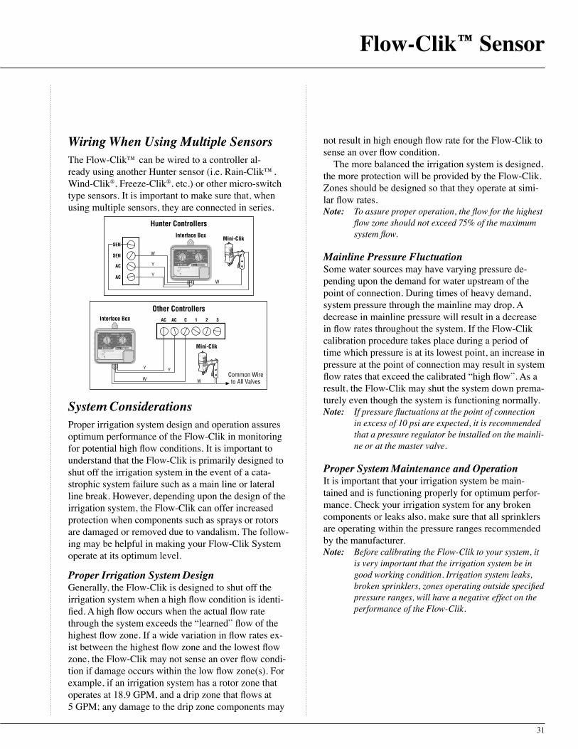
31
Wiring When Using Multiple SensorsThe Flow-Clik™ can be wired to a controller al-ready using another Hunter sensor (i.e. Rain-Clik™, Wind-Clik®, Freeze-Clik®, etc.) or other micro-switch type sensors. It is important to make sure that, when using multiple sensors, they are connected in series.
Hunter Controllers
Mini-Clik
AC
AC
SEN
Interface Box
Y
Y
W
W
SEN
1 2 3Interface Box C
Common Wireto All Valves
AC AC
Y
W
Mini-Clik
Y
W
Other Controllers
System ConsiderationsProper irrigation system design and operation assures optimum performance of the Flow-Clik in monitoring for potential high flow conditions. It is important to understand that the Flow-Clik is primarily designed to shut off the irrigation system in the event of a cata-strophic system failure such as a main line or lateral line break. However, depending upon the design of the irrigation system, the Flow-Clik can offer increased protection when components such as sprays or rotors are damaged or removed due to vandalism. The follow-ing may be helpful in making your Flow-Clik System operate at its optimum level.
Proper Irrigation System DesignGenerally, the Flow-Clik is designed to shut off the irrigation system when a high flow condition is identi-fied. A high flow occurs when the actual flow rate through the system exceeds the “learned” flow of the highest flow zone. If a wide variation in flow rates ex-ist between the highest flow zone and the lowest flow zone, the Flow-Clik may not sense an over flow condi-tion if damage occurs within the low flow zone(s). For example, if an irrigation system has a rotor zone that operates at 18.9 GPM, and a drip zone that flows at 5 GPM; any damage to the drip zone components may
not result in high enough flow rate for the Flow-Clik to sense an over flow condition.
The more balanced the irrigation system is designed, the more protection will be provided by the Flow-Clik. Zones should be designed so that they operate at simi-lar flow rates.Note: To assure proper operation, the flow for the highest
flow zone should not exceed 75% of the maximum system flow.
Mainline Pressure FluctuationSome water sources may have varying pressure de-pending upon the demand for water upstream of the point of connection. During times of heavy demand, system pressure through the mainline may drop. A decrease in mainline pressure will result in a decrease in flow rates throughout the system. If the Flow-Clik calibration procedure takes place during a period of time which pressure is at its lowest point, an increase in pressure at the point of connection may result in system flow rates that exceed the calibrated “high flow”. As a result, the Flow-Clik may shut the system down prema-turely even though the system is functioning normally.Note: If pressure fluctuations at the point of connection
in excess of 10 psi are expected, it is recommended that a pressure regulator be installed on the mainli-ne or at the master valve.
Proper System Maintenance and OperationIt is important that your irrigation system be main-tained and is functioning properly for optimum perfor-mance. Check your irrigation system for any broken components or leaks also, make sure that all sprinklers are operating within the pressure ranges recommended by the manufacturer.Note: Before calibrating the Flow-Clik to your system, it
is very important that the irrigation system be in good working condition. Irrigation system leaks, broken sprinklers, zones operating outside specified pressure ranges, will have a negative effect on the performance of the Flow-Clik.
Flow-Clik™ Sensor

Valve 4 (18.9 GPM)Operating pressure = 50 psi
32
Calibrating the Flow-Clik™ to the Irrigation SystemUsing the Flow-Clikʼs Interface Box, the sensor is calibrated by pressing the Calibrate button while the highest flow zone is operating. While the system is “learning” the flow, the System Status Indicator light will be yellow. After a 10 second period of “learning” it will begin to monitor system flow.
If you already know the highest flow zone within the system:1. Turn the Startup Delay dial to the 0 second position.2. Turn the Interrupt Period dial to the Sensor Bypass/
Calibrate position.3. Manually activate the zone with the highest flow.4. While the zone is operating, press and hold the
Calibrate button on the Interface Box. The System Status Indicator light will change to yellow indicat-ing that the sensor is being calibrated to the zone(s) operating. Release the calibrate button. Once the Flow-Clik has finished “learning” the systemʼs high flow zone, the light will turn to flashing green which means that the calibration process is complete.
5. Turn the irrigation system off and set the Startup De-lay and Interrupt Period settings on the Interface Box (see Setting the Startup Delay and Interrupt Period).
If you do not know the highest flow zone within the system:
Flow Estimate Calibration MethodIn some cases, you may not know the zone with the highest flow. A guideline that will help you easily de-termine which zone valve has the highest flow (GPM) is to count the number of sprinklers on each zone. If there are zones with both sprays and rotors operating in the irrigation system, you can multiply each spray head by 2.0 GPM, each medium range rotor by 4.0 GPM, and each large range rotor by 15.0 GPM for a general estimate of total flow for each zone.
For a more accurate determination of total flow for each zone, it is recommended that you measure the nozzle pressure at each sprinkler zone and then look up the nozzle flow at that specific pressure in the nozzle performance data section of the manufacturer product catalog. Once a determination is made of the highest flow zone, you can use the procedure above to calibrate the Flow-Clik to the system.
For example, Figure 1 shows a typical zone using I-20 rotors. To estimate the total flow of the zone:1. Determine the approximate water pressure at the base
of the sprinklers in each zone while the system is operating. In the illustrative example it has been deter-mined that the sprinkler pressure in zone 4 is 50 psi.
2. Identify the model of sprinkler and its associated nozzle for each valve. Valve 4 has Hunter I-20 rotors that have various nozzles based on the dis-tance of throw and the arc of coverage needed. For reference, the quantities of each type of sprinkler and nozzle configuration for zone 4 is identified in the attached irrigation legend.
3. Determine the flow rate for each sprinkler and nozzle configuration. Based upon information found in the Hunter Catalog the associated flows for each Hunter I-20 sprinkler and nozzle configuration is listed in the attached irrigation legend.
4. Determine the total flow of all sprinklers on the zone. The total flow of zone 4 in this example is 18.9 GPM as identified in the irrigation legend.
Symbol Sprinkler Description *Flow @ 50 psi
Qty Total Flow
Hunter I-20-ADS – 1.5 1.6 x 3 = 4.8
Hunter I-20-ADS – 3.0 2.7 x 2 = 5.4
Hunter I-20-ADS – 4.0 4.2 x 1 = 4.20
Hunter I-20-ADS – .75SR .75 x 2 = 1.50
Hunter I-20-ADS – 1.5SR 1.5 x 2 = 3.0
Total Flow = 18.9 GPM*Information obtained from the Hunter catalog, LIT-060
Figure 1 Legend
INSTALLATION INSTRUCTIONS (continued)
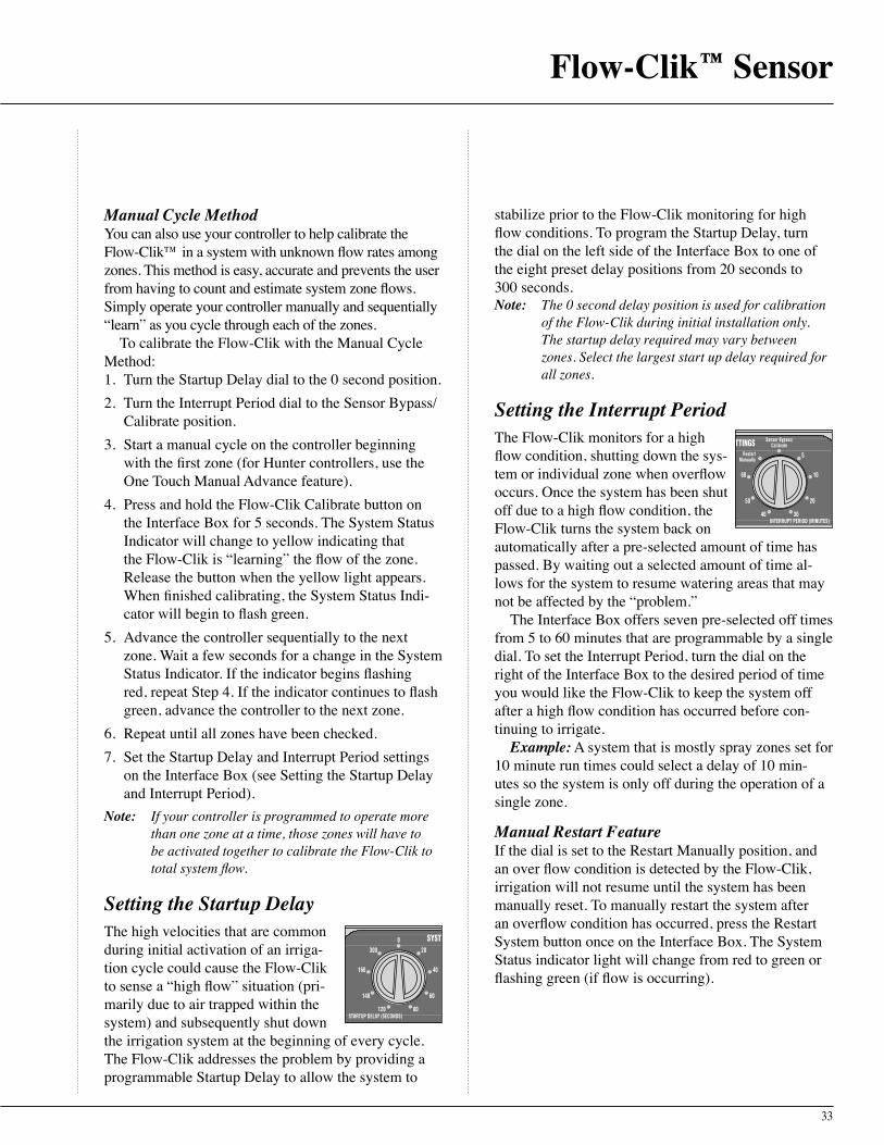
33
Manual Cycle MethodYou can also use your controller to help calibrate the Flow-Clik™ in a system with unknown flow rates among zones. This method is easy, accurate and prevents the user from having to count and estimate system zone flows. Simply operate your controller manually and sequentially “learn” as you cycle through each of the zones.
To calibrate the Flow-Clik with the Manual Cycle Method:1. Turn the Startup Delay dial to the 0 second position.2. Turn the Interrupt Period dial to the Sensor Bypass/
Calibrate position.3. Start a manual cycle on the controller beginning
with the first zone (for Hunter controllers, use the One Touch Manual Advance feature).
4. Press and hold the Flow-Clik Calibrate button on the Interface Box for 5 seconds. The System Status Indicator will change to yellow indicating that the Flow-Clik is “learning” the flow of the zone. Release the button when the yellow light appears. When finished calibrating, the System Status Indi-cator will begin to flash green.
5. Advance the controller sequentially to the next zone. Wait a few seconds for a change in the System Status Indicator. If the indicator begins flashing red, repeat Step 4. If the indicator continues to flash green, advance the controller to the next zone.
6. Repeat until all zones have been checked.7. Set the Startup Delay and Interrupt Period settings
on the Interface Box (see Setting the Startup Delay and Interrupt Period).
Note: If your controller is programmed to operate more than one zone at a time, those zones will have to be activated together to calibrate the Flow-Clik to total system flow.
Setting the Startup DelayThe high velocities that are common during initial activation of an irriga-tion cycle could cause the Flow-Clik to sense a “high flow” situation (pri-marily due to air trapped within the system) and subsequently shut down the irrigation system at the beginning of every cycle. The Flow-Clik addresses the problem by providing a programmable Startup Delay to allow the system to
stabilize prior to the Flow-Clik monitoring for high flow conditions. To program the Startup Delay, turn the dial on the left side of the Interface Box to one of the eight preset delay positions from 20 seconds to 300 seconds.Note: The 0 second delay position is used for calibration
of the Flow-Clik during initial installation only. The startup delay required may vary between zones. Select the largest start up delay required for all zones.
Setting the Interrupt PeriodThe Flow-Clik monitors for a high flow condition, shutting down the sys-tem or individual zone when overflow occurs. Once the system has been shut off due to a high flow condition, the Flow-Clik turns the system back on automatically after a pre-selected amount of time has passed. By waiting out a selected amount of time al-lows for the system to resume watering areas that may not be affected by the “problem.”
The Interface Box offers seven pre-selected off times from 5 to 60 minutes that are programmable by a single dial. To set the Interrupt Period, turn the dial on the right of the Interface Box to the desired period of time you would like the Flow-Clik to keep the system off after a high flow condition has occurred before con-tinuing to irrigate.
Example: A system that is mostly spray zones set for 10 minute run times could select a delay of 10 min-utes so the system is only off during the operation of a single zone.
Manual Restart FeatureIf the dial is set to the Restart Manually position, and an over flow condition is detected by the Flow-Clik, irrigation will not resume until the system has been manually reset. To manually restart the system after an overflow condition has occurred, press the Restart System button once on the Interface Box. The System Status indicator light will change from red to green or flashing green (if flow is occurring).
Flow-Clik™ Sensor

34
Sensor BypassThe Sensor Bypass setting allows the user to manu-ally override the Flow-Clik™ sensor. This is helpful during situations that require the system to operate at higher than “learned” flow rates (i.e. system winteriza-tion, running a hose bib, or operating multiple valves). To bypass the Flow-Clik sensor, turn the interrupt period dial to the Sensor Bypass/Calibrate position.
PROBLEM CAUSES SOLUTIONSSystem Status Indicator light is off
No AC power to the Flow-Clik Interface Box A) Check that the Interface Box power leads (yellow wires) are attached to the 24 VAC terminals on the controller.
B) Verify that the power to the controller is on.
System Status Indicator light is flashing red
Irrigation system is in an overflow condition Normal operation during an overflow condition. The Flow-Clik has identified overflow condition and is waiting the pre-set startup delay period before shutting the system off.
System Status Indicator is steady red
Irrigation system is in an overflow condition Normal operation during an overflow condition. A) The Flow-Clik has identified an overflow condition and is waiting the
predetermined amount of time set as the Interrupt Period before restarting the irrigation cycle.
B) The Interrupt Period setting is in the Manual Restart position requiring the Flow-Clik be reset before irrigation can resume. Press the Restart System button to reactivate the Flow-Clik.
Flow-Clik will not shut the irrigation system off
No power to Flow-Clik Check System Status Indicator light is on (if light is off, see above).
Faulty wire connections from the Flow-Clik sensor to the Interface Box
Check Flow-Clik sensor wires (red and black wires) are properly connected.
System is in the Startup Delay mode A) Normal operation.B) System is not balanced. Too much variation between flow rates of the zones
may prevent the Flow-Clik from sensing an overflow condition on the lower flow zone(s). Flow-Clik will only shut the system down if flows exceed highest flow zone.
Wait for start up delay period to end.
Flow-Clik continually shuts off a zone with no known problems
Flow-Clik is improperly calibrated Reset the Flow-Clik to the highest flow zone.
High fluctuations in system pressure It is recommended that the Flow-Clik be set at the time of day that the irrigation system will be run. Note: If too much pressure fluctuation occurs, it may be necessary to add pressure regulation to the system.
System Status Indicator light is not Flashing Green when the system is running
Faulty wiring connections from the Flow-Clik sensor to the Interface Box
Check Flow-Clik sensor wires (red and black wires) are properly connected.
AC power not being supplied to the Interface Box
Check the wiring connections from the controller to the Interface Box.
Debris is stuck in the impeller of the Flow-Clik sensor
Confirm that system pressure is off. Remove cap and pull sensor out of the sensor body and inspect for debris or damage to the impeller.
System Status Indicator is Flashing Red/Green
System experienced an overflow condition during an automatic watering cycle.
Manually cycle system to find cause of system overflow.Press the Restart/Calibrate button to reset the system status indicator.
TROUBLESHOOTING GUIDE
If the sensor experiences an overflow condition, the system status indicator will identify the overflow, but the interface box will continue to allow the controller to operate.
INSTALLATION INSTRUCTIONS (continued)

35
ModelsOperating Specifications
Temperature: 0 to 150 degrees FPressures: up to 200 PSIHumidity: up to 100%
Additional FeaturesProgrammable Start Up Delay (0 to 300 seconds)Programmable Interrupt Period (2 to 60 minutes)System Status Indicator LightOne Button System Calibration
FLOW RANGE
Flow Sensor Diameter
Operating Range (GPM)
Minimum* Suggested Maximum** Maximum (for sensor)
1" 6 17 501½" 13 35 1002" 20 55 2003" 40 120 3004" 60 200 400
* Minimum recommended flow for the highest flow zone for your system** Good design practice dictates the maximum flow not to exceed 5ft/sec.
Suggested maximum flow is based upon Class 200 IPS plastic pipe
Electrical SpecificationsCurrent Draw: (@ 24VAC) .025 ampsSwitching Current: 2.0 ampsMaximum Distance between Interface Box and Sensor = 1,000 ft.
DimensionsFlow-Clik Interface Box (4.5"H x 5.5"W x 1.5"D)Flow-Clik Sensor Body (FCT Series)FCT 100 (4.8"H x 2.3"W x 4.5"L)FCT 150 (5.4"H x 2.3"W x 4.6"L)FCT 158 (5.4"H x 2.3"W x 5.1"L)FCT 200 (5.9"H x 2.7"W x 4.7"L)FCT 208 (6.0"H x 2.9"W x 5.4"L)FCT 300 (7.0"H x 4.0"W x 6.2"L)FCT 308 (7.0"H x 4.2"W x 6.4"L)FCT 400 (6.5"H x 5"W x 6.5"L)
FEATURES Hunter ® Flow-Clik™ Data Industrial 200 Series Rain Bird FS-P Series
Flow monitoring for less than $200 (1½" vavle) √
Programmable startup delay 20-300 sec. up to 100 sec.
User adjustable set point √ √
Programmable automatic controller reset 2-60 min. manual reset
Fast, easy hookup on any Hunter controller √
Easily adaptable to other manufacterrs controllers √ Needs separate relay control(LARC) and relays
Separate transmitter,power supply and software
Installation type Male Threaded Tee Saddle tee Glue-in Tee
Pressure: up to 150 PSI √
Rain Bird® is a registered trademark of Rain Bird Sprinkler Manufacturing CorporationData Industrial® is a registered trademark of Data Industrial Corporation
FLOW SENSOR PRODUCT COMPARISON
S P E C I F I C A T I O N G U I D E
EXAMPLE: FLOW-CLIK - 150
MODELFLOW-CLIK = Standard Ver-sion for all 24VAC Controllers (includes sensor and interface panel)FLOW-CLIK IMMS = Version for use with IMMS™ Central Control (includes sensor only - interface panel not required for IMMS™)
FEATURES100 = 1" Schedule 40 Sensor Body150 = 1½" Schedule 40 Sensor Body158 = 1½" Schedule 80 Sensor Body200 = 2" Schedule 40 Sensor Body208 = 2" Schedule 80 Sensor Body300 = 3" Schedule 40 Sensor Body308 = 3" Schedule 80 Sensor Body400 = 4" Schedule 40 Sensor Body
NOTE = Order Flow-Clik Sensor Bodies Separately (FCT series)
SPECIFICATIONS
Flow-Clik™ Sensor

36
All of the answers to this quiz are contained in this training manual. Answers to the question can be found on page 37.1. Hunter markets weather sensors and ____ sensors.2. Which Hunter rain sensor shuts the system off within a
few minutes of a downpour?_________ This trademarked feature is called _________™.
3. The calibrated vent ring located on the Rain-Clik™ can be adjusted to control the time it takes to dry out the hygroscopic discs, which in turn will keep the system from operating for a minimum of _____ to a maximum of _____ after the rain stops falling.
4. The Rain-Clik and Mini-Clik® rain sensors come with __ feet of attached control wire providing for fast and efficient installation. To extend the total distance of the sensor from the controller to 105 feet, a minimum of __ gauge wire can be attached to the integral wire utilizing waterproof connections.
5. Hunter rain and wind sensors cannot be wired in series to provide the ability to shut down an irrigation system due to excessive rain or wind. True or False
6. The Wireless Rain-Clik™ provides for quick, effortless installation on retrofit sites as well as problematic sites in which it is difficult to run wire from the controller to the sensor installation. The Wireless Rain-Clik can be installed up to ___ feet from the controller.
7. The Mini-Clik has ____ adjustment settings. An irriga-tion system will be shut down once the device has col-lected a set amount of irrigation based on the setting. The settings provide a range of ___ inch to __ inch
8. Hunter offers a version of the Mini-Clik that can be attached to ½" conduit for markets that require all wires to be placed in a conduit. The model is a ____________.
9. Hunter Mini-Clik and Rain-Clik Sensors utilize ____________ discs that expand proportionately relative to the amount of rainfall that the sensor device collects. As these discs absorb water they expand in height reaching a set point in which an integral ____________ in the device is held open to interrupt the circuit and disable the controller from irrigating. After the rain stops, the disks shrink in size releasing the ____________, allowing the controller to irrigate during its next programmed cycle.
10. Hunter controllers incorporate an integral ____________ switch which enables the irrigation system to operate independent of sensor control.
11. For controllers that do not have a built in sensor bypass, a Hunter Model _____ can be utilized by interrupting the valve ________ wire.
12. With a Hunter Wind-Clik® installed and activated, an irrigation system will shut down when the wind speed is between __ and __ miles per hour.
13. The Hunter ____________ automatically shuts down the irrigation system when the temperature drops below freezing (32˚F) and allows the system to start operating again when the temperature reaches approximately 37˚F.
14. A Hunter Freeze-Clik® sensor can be disabled by utiliz-ing the manual bypass switch on the controller. True or False
15. The mini weather station that incorporates a rain sensor, wind sensor and a freeze sensor in one unit is a Hunter ________ model.
16. The Hunter Flow-Clik™ is an _________, _____, and ________ flow monitoring system that shuts down a system or valve when flow through the device has __________ a pre-set amount minimizing water waste and potential liability due to erosion caused by excessive runoff.
17. A Flow-Clik Sensor ______________ is wired into the controller terminal strip providing LED displays which identify specific flow conditions. A ____ light indicates that the irrigation system is shut down due to an overflow condition that occurred. A ____ light indicates an accept-able amount of water is flowing.
18. A Flow-Clik can be installed up to a maximum of _____ feet provided __ gauge wire is used.
19. Increased start-up flow velocities won't effect flow sensor readings as the user can program a start up delay of ______ to ______ seconds by simply turning a dial to a set position on the Sensor Interface box.
20. The unit is easy to calibrate as the user simply pushes a button on the interface box while the _________ flow valve is operating.
21. The flow range for a 1½" inch Flow-Clik is from ____ to ____ GPM.
22. When installing a Flow-Clik™ it is important to allow for a straight pipe run into the device of at least __ times the pipe diameter and on the outlet side at least __ times the pipe diameter.
SENSORS TRAINING MANUAL QUIZ

37
QUIZ ANSWERS
1. flow (pg.4) 2. Rain-Clik, quick response (pg.5) 3. 2 hours, 3 days (pg.5) 4. 25 (pg.6), 16 (pg.7) 5. False (pg.7) 6. 300 (pg.10) 7. five, 1/8, 1 (pg.14) 8. Mini-Clik-C (pg.14) 9. hygoscopic, switch, switch (pg.13) 10. sensor bypass (pg.24) 11. BPSW, common (pg.24) 12. 12, 35 (pg.20) 13. Freeze-Clik (pg.21) 14. False (pg.23) 15. MWS-FR (pg.23) 16. affordable, rugged, reliable, exceeded (pg.25) 17. Interface Box, red, green (pg.26) 18. 1000, 14 (pg.27) 19. 20 to 300 (pg.27) 20. highest (pg.27) 21. 6 to 120 (pg.27) 22. 10, 5 (pg.29)
Sensors Quiz


Hunter Industries Incorporated • The Irrigation Innovators © 2005 Hunter Industries Incorporated
1940 Diamond Street • San Marcos, California 92078 • TEL: (1) 760-744-5240 • FAX: (1) 760-744-7461www.HunterIndustries.com P/N 700676 LIT-293 4/05