sensitivity analysis of stability and behavior of ... · building failure and related human...
TRANSCRIPT
International Journal of Civil & Environmental Engineering IJCEE-IJENS Vol:13 No:01 13
133001-7575-IJCEE-IJENS © February 2013 IJENS I J E N S
Abstract— After earthquakes it becomes very visible what types
of building construction have withstood the forces of the
earthquake and which did not perform adequately. Analyzing
the nearly collapsed and broken structures gives a good insight
in the possible architectural and engineering design mistakes,
faults in the detailing and the mismanagement of the
construction by the building contractors. Stability calculations
are critical in structural design can cause significant damage to
structural column members. In discussing the stability of
structural systems, the goal is the investigation of the
equilibrium condition from the point view of stability and
instability and determines the conditions which make the
system unstable. The stability is considered for relatively thin
columns with small cross section area like steel sections and is
rarely discussed in usual problems of structural engineering
related to reinforced concrete sections and is propounded in
special structures. Concrete is a non-homogeneous and
anisotropic material. Modeling the mechanical behavior of
Reinforced Concrete (RC) is still one of the most difficult
challenges in the field of structural engineering. There are
some factors which cause the mechanical factors of concrete in
right dimension are not uniform and isotropic in high columns.
These factors effect on concrete elasticity modulus, Poisson
coefficient and regular relations of columns critical load. In this
research, sensitivity analysis of critical load or stability of
inhomogeneous orthotropic reinforced concrete columns based
on various design codes has been investigated. Due to the
numerous outputs obtained, software package have been written
in Matlab and analysis on data and drawing related charts have
been done.
Index Term— Concrete Columns, Elastic & Inelastic Stability,
Inhomogeneous, Sensitivity Analysis.
This work was run as Ph.D. project and this research was conducted
from 6/2011 to 8/2012. The Research Project was partially sponsored
by the “FARBANA Consulting Engineers”, No 447, Hafez St., Panjraah,
Urmia, IRAN.
L. S., V. PhD. Student of civil engineering, AZUAC, Azerbaijan
University Of Architecture and Construction, +98-441-2231150; +98-
914-141-8577; e-mail: [email protected].
T . S. MSc. Student of civil engineering, Azad University of Mahabad,
designer of the structural dept., Farbana Consulting Engineers.
I. INTRODUCTION
Most structural failures are the result of an error made by one
of the people involved in the great number of steps between
the original idea and the completion of the final structure. For
reinforced concrete construction, mainly inadequate column
designs and over-weight structures are the cause of fatal
building failure and related human victims.
Columns are structural members in buildings carrying roof
and floor loads to the foundations. Most columns are termed
short columns and fail when the material reaches its ultimate
capacity under the applied loads and moments. The limit loads
for columns, having major importance to a building’s safety,
are considered stability limits. Thus, a designer must evaluate
the critical load limits. In reality, some of the design parameters
in structural analysis may be disregarded which can lead to
uncertainties.
Buckling, also known as structural instability may be
classified into two categories: 1, bifurcation buckling and 2,
limit load buckling. In bifurcation buckling, the deflection
under compressive load changes from one direction to a
different direction (e.g., from axial shortening to lateral
deflection). The load at which the bifurcation occurs in the
load-deflection space is called the critical buckling load or
simply critical load. In limit load buckling, the structure attains
a maximum load without any previous bifurcation, i.e., with
only a single mode of deflection, [1].
The first study on elastic stability is attributed to Leonhard
Euler [1707–1783], who used the theory of calculus of
variations to obtain the equilibrium equation and buckling load
of a compressed elastic column, (1). Most basic linear elastic
problems of structural stability were solved by the end of the
19th century, although further solutions have been appearing
as new structural types were being introduced. In discussing
the stability of structural systems, the goal is the investigation
of the equilibrium condition from the point view of stability and
instability and determines the conditions which make the
system unstable, [2~5].
Slender columns buckle and the additional moments caused
by deflection must be taken into account in design. 1, Short
columns when the ratios lex/h and ley/b are both less than 15 for
braced columns and less than 10 for un-braced columns and 2,
Slender columns when the ratios are larger than the values
given above. The buckling load of stocky columns must be
Sensitivity Analysis of Stability and Behavior
of Inhomogeneous Concrete Columns Based on
Design Codes
L. Shahsavar, Vahid, Tofighi, Samira

International Journal of Civil & Environmental Engineering IJCEE-IJENS Vol:13 No:01 14
133001-7575-IJCEE-IJENS © February 2013 IJENS I J E N S
determined by taking into consideration the inelastic behavior,
(Euler, 1744) [4].
(1)
Where E is the modulus of elasticity of the column member
representing the material property, I is the area moment of
inertia of the cross-section, k is the column effective length
factor, whose value depends on the conditions of end support
of the column and L is the length of the column.
In this research, critical load or stability of inhomogeneous
reinforced concrete columns have been investigated. To do
this, sensitivity analysis of critical loads to various parameters
such as E, I and L have been investigated. Also studying has
been done on a set of concrete columns with and without
inhomogeneous properties. The column section is generally
square or rectangular, but circular and polygonal columns are
used in special cases. Consider now columns of square cross
sections. The column slenderness is defined as L/r, where
r=h/120.5 and h=side of the square cross section = 150mm. In
numerical calculations, f’c=250 kg/cm2 is considered. The
column is reinforced symmetrically by eight axial steel bars and
the steel ratio ρ=0.01 and 0.03. The cover of concrete bars is
such that the axial bar centers are about 50 mm from the
surface. Furthermore, Es=2e6 kg/cm2 and fy=4000 kg/cm
2.
II. MATERIAL PROPERTIES
A. Concrete Strength
Material properties affect the critical value of the buckling
loads. Concrete strength is counted as one of the important
parameters for the material properties in reinforced concrete
structure design. The material modeling of reinforced concrete
consisting generally of three phases: cement mortar, aggregate
grains and reinforcing steel bars, is a strong compromise
between the structural phenomena and available material
parameters. In structural analysis, reinforced concrete materials
are modeled as a macroscopically homogeneous material with
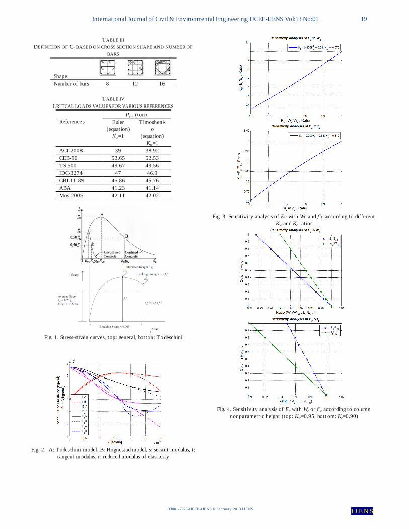
response influences by each of the phases. Stress-strain
curves are an extremely important graphical measure of a
material’s mechanical properties, (Fig. 1).
B. Modulus of Elasticity
Material properties can be defined through concrete
strength and modulus of elasticity as proposed in different
national building codes through various formulas for the same
values of concrete strength (Fig. 2). Modulus of elasticity of
concrete is a key factor for estimating the deformation of
buildings and members, as well as a fundamental factor for
determining modular ratio, n, which is used for the design of
section of members subjected to flexure. Modulus of elasticity
of concrete is frequently expressed in terms of compressive
strength. In the present study, selected seven different design
codes were considered in the analyses (table I). Slope of
stress-strain curve is defined as elasticity modulus in concrete.
This modulus relates to the kind of concrete, concrete age
and speed in loading, concrete properties and mixing percent
and more importantly relates to definition of concrete elasticity
modulus. According to table I, the two factors, compressive
strength and weight, have relations with elasticity modulus. In
concreting, by being careful about how to compact the
concrete and its completion, the concrete will have much
compressive strength. So all the aspects that influence in
compressive strength and weight have in direct influence in
elasticity modulus too.
C. Inhomogeneous Behavior of Concrete
Using the same mixing, concrete could get different
Compressive strength results in different situations. Following
is some of effective factors on compressive strength of
concrete. The compressive strength of concrete depends on
some main factors for examples the aggregate grading,
aggregate/cement ratio as well as the water/cement ratio. Also
depends on some minor factors or site factors for examples
grout leakage, poor compaction (the influence of gravity force
on concentration of layers and type of concrete compression
vibration), segregation, grading limits, poor curing and
Chemical attacks such as chlorides, sulfates, carbonation,
alkali-silica reaction and acids. Some studies show that
humidity and good temperature in concreting after 180 days
can increase the concrete strength to 3 times. In those seasons
with straight sunshine, the temperature increases and humidity
of concrete section decreases 2 or 3 degrees. This factor is
important in column sections and surrounding beam sections
of roofs.
Concrete exhibits a large number of micro-cracks, especially
at the interface between coarser aggregates and mortar, even
before the application of any external loads. The presence of
these micro-cracks has a great effect on the mechanical
behavior of concrete, since their propagation (concrete
damage) during loading contributes to the nonlinear behavior
at low stress levels and causes volume expansion near failure.
Many of these micro-cracks are initially caused by segregation,
shrinkage or thermal expansion of the mortar. Some micro-
cracks may develop during loading because of the difference in
stiffness between aggregates and mortar, (Mostofinejad, 2006,
Tim Gudmand-Høyer and Lars Zenke Hansen, 2002), [6,7].
For example a reinforced concrete column with known high
is supposed. Regarding to the column height, concreting may
be done in 2 or more steps. Segregation that cause by levels
and height of concreting and poor compacting of concrete may
change the density of column concrete. If density of the
concrete in bottom section of the column (x/L=0) equals to Wc,
then the density at the top of the column section (x/L=1) would
be Kw*Wc. Where Kw is the coefficient smaller than one and
shows the density differences of bottom and top. For instance
Kw=0.95 means the density of concrete in top of the column is
95% of density of the bottom. Sensitivity analysis of elasticity
modulus to various ratios of Kw, suppose of constant
compressive strength of concrete is shown in Fig. 3a.
With a change in concreting and compacting methods, the
compressive strength in bottom and top of the column will be
different. If the compressive strength of the concrete in bottom
section of column (x/L=0) equals to f’c, then the strength at the
International Journal of Civil & Environmental Engineering IJCEE-IJENS Vol:13 No:01 15
133001-7575-IJCEE-IJENS © February 2013 IJENS I J E N S
top of the column section (x/L=1) would be Kc*f’c. Where Kc is
the coefficient smaller than one and shows the compressive
strength differences of bottom and top. For instance Kc=0.95
means the compressive strength of concrete in top of the
column is 95% of compressive strength of the bottom.
Sensitivity analysis of elasticity modulus to various ratios of
Kc, suppose of constant density of concrete (kw=1) is shown in
Fig. 3b.
In practice, with a change in gradation and concrete
compaction, the density and the compressive strength of
concrete are change (table II). It may happen that with a small
change in density and without any external interference, the
compressive strength of concrete decrease due to the decrease
in density, it means if Kw=0.95 then Kc may equals to 0.9.
Sensitivity analysis of modulus of elasticity with both Kw and
Kc is shown in Fig. 4. If the density of concrete in top of the
column is %95 of the density in bottom and it may cause that
the compressive strength in top of the column be %90 of the
bottom, thus the elasticity modulus of concrete in top of the
column become %88 of the elasticity in bottom, (Fig. 5).
In this form the elasticity follows a second order equation
(KE). This second order equation shows the inhomogeneous
behavior of concrete in column height and one can calculate
the critical load. These second order equation is used to
estimate the changes of elasticity modulus, (Vahid Shahsavar,
2010 [8].
(2)
III. STABILITY PROBLEM
A. Eigenvalue and stability of Column
Instability of linear elastic columns is analyzed by the energy
method. The energy method for a column provides a criterion,
which determines whether the column is stable or not.
(3)
Where v is shape function and,
(4)
(5)
(6)
(7)
(8)
(9)
(10)
To compare the critical load for liner (first order) equation
of elasticity modulus is also estimated.
(11)
(12)
(13)
Supposing a liner relation of elasticity modulus of concrete
in column height instead of second order equation, critical load
of first mood of buckling has %0.032 error and the error of
second buckling mood is %0.044. Column critical load by
homogeneous behave of concrete with unique length of
column will be 9.869 EI. It means that if changing of the
elasticity modulus equals to KE=0.88 then the critical load
decrease from 9.869 to 9.261, around %94.
B. Sensitivity of Critical Buckling Load on Material
Properties
There are various research works available in the literatures
for determining sensitivity of modulus of elasticity to concrete
strengths. In this study, a procedure was taken into account to
investigate the effect of material uncertainty. In the present
study, selected seven different design codes were considered
in the analyses (table I). Relationships of f’c and Ec are
expressed in MPa and in GPa, respectively. Relationship
curves of elasticity Modulus and various concrete strengths
for different design codes are shown in Figs. 6 and 7, (Korkmaz
et al., 2011, Mostofinejad, 2006), [5,6].
C. Tangent-Modulus Theory
According to the tangent-modulus theory (Engesser
theory) of inelastic buckling, column remains straight until
inelastic critical load is reached. At that value of load, the
column may undergo a small lateral deflection. The resulting
bending stresses are superimposed upon the axial compressive
stresses SA. Since the column starts bending from a straight
position, the initial bending stresses represent only a small
increment of stress. Therefore, the relationship between the
bending stresses and the resulting strains is given by the
tangent modulus. Since the tangent modulus Et varies with the
compressive stress SP/A, we usually obtain the tangent-
modulus load by an iterative procedure.
(14)
(15)
(16)
(17)
(18)
(19)
Where fc
is the compressive stress, fck
is the characteristic
compressive strength of cubes, εc
is the compressive strain, ε0
International Journal of Civil & Environmental Engineering IJCEE-IJENS Vol:13 No:01 16
133001-7575-IJCEE-IJENS © February 2013 IJENS I J E N S
is the strain corresponding to fck
= 0.002, εcu
is the ultimate
compressive strain = 0.003 (Based on Todeschini concrete
stress-strain equation).
D. Reduced-Modulus Theory
The tangent-modulus theory is distinguished by its
simplicity and ease of use. However, it is conceptually
deficient because it does not account for the complete
behavior of the column. The results of such analyses show
that the column bends as though the material had a modulus of
elasticity between the values of E and Et. This “effective
modulus” is known as the reduced modulus Er , and its value
depends not only upon the magnitude of the stress (because
Et depends upon the magnitude of the stress) but also upon
the shape of the cross section of the column. Thus, the
reduced modulus Er is more difficult to determine than is the
tangent modulus Et. In the case of a column having a
rectangular cross section, the equation for the reduced
modulus is:
(20)
(21)
(22)
E. Effects of Confinement on Interaction Diagrams
The effects of confinement on a structural column in a
building are mainly due to the presence of lateral reinforcement
provided over the column height. It results in higher capacity
and ductility of a column that help to prevent the column from
brittle failure. Several stress-strain relationships of confined
concrete available in literature such as Kent-Park, Sheikh-
Uzumeri, Mander et al., Yong-Nawy, Cusson- Paultre, Diniz-
Frangopol, Kappos- Konstantinidis, Hong-Han, and Kusuma-
Tavio. Kent-Park and Mander et al relationships are adopted in
the study. Also the unconfined concrete model adopted in the
study is Todeschini stress-strain model, (Tavio, 2008), [9].
F. Elastic Second-Order Analysis
In defining the critical load, the main problem is the choice
of stiffness EI that reasonably approximates the variations in
stiffness due to cracking, creep, and nonlinearity of the
concrete stress-strain curve. Second-order analysis shall
consider material nonlinearity, member curvature and lateral
drift, duration of loads, shrinkage and creep, and interaction
with the supporting foundation. The analysis procedure shall
have been shown to result in prediction of strength in
substantial agreement with results of comprehensive tests of
columns in statically indeterminate reinforced concrete
structures. Elastic second-order analysis shall consider section
properties determined taking into account the influence of axial
loads, the presence of cracked regions along the length of the
member, and the effects of load duration. The stiffness (EI)
used in an analysis for strength design should represent the
stiffness of the members immediately prior to failure. This is
particularly true for a second-order analysis that should predict
the lateral deflections at loads approaching ultimate, (Tavio,
2009), [10]. The moments of inertia of compression and flexural
members, I, shall be permitted to be computed as follows (ACI-
318):
(23)
Where Ast is the rebar’s area, Ag is the gross section area, Pu
and Mu are the factored loads and P0 is the critical buckling
load for the column. Pu and Mu shall be determined from the
particular load combination under consideration or the
combination of Pu and Mu determined in the smallest value of I.
I need not be taken less than 0.35Ig.
When sustained lateral loads are present, I for compression
members shall be divided by (1 + βd). The term βd is the ratio of
maximum factored sustained shear within a story to the
maximum factored shear in that story associated with the same
load combination, but shall not be taken greater than 1.0.
In lieu of a more precise analysis EI may be taken either as:
(24)
(25)
(26)
(27)
Where Ct introduced in table III. The greatest emphasis is
currently being placed on the analysis of instabilities and
bifurcations caused by propagation of softening damage or
fracture in materials, which is important not only from the
physical and engineering viewpoint, but also from the
viewpoint of computational modeling. Fig. 8 shows cracked
moments of inertia of compression and flexural members
according to different reinforcement ratios. Also fig. 9 shows
variety of EImm values according to different reinforcement
ratios.
The deformations due to shear forces are neglected in the
classical ending theory, since the cross sections are assumed
to remain normal to the deflected beam axis. This assumption is
usually adequate; however, there are some special cases when
it is not. The shear deformations can be taken into account in a
generalization of the classical bending theory called
Timoshenko beam theory. Usually elastic modulus changes
with critical loads, fig 10.
When the column is stocky, or built up (latticed or
battened) or of a composite-type construction, the application
of Euler (classical) beam theory will overestimate the buckling
loads. This is due to the neglect of transverse shear
deformation in the Euler beam theory. A more refined beam
theory, known as the first-order shear deformation theory or
Timoshenko beam theory, that incorporates the shear
deformation effect was proposed by Engesser (1891) and
Timoshenko (1921). According to the Engesser–Timoshenko
beam theory, the stress–resultant–displacement relations are
given by:
International Journal of Civil & Environmental Engineering IJCEE-IJENS Vol:13 No:01 17
133001-7575-IJCEE-IJENS © February 2013 IJENS I J E N S
(28)
(29)
In which is the longitudinal coordinate measured from the
column base, M the bending moment, V the transverse shear
force, θ the rotation in the Engesser–Timoshenko column and
w the transverse deflection. The shear correction coefficient Ks
in the (29) is introduced to account for the difference in the
constant state of shear stress in the Engesser–Timoshenko
column theory and the parabolic variation of the actual shear
stress through the depth of the cross -section, (Bazant, 2000,
Timoshenko, 1921), [1,11].
(30)
Where ,
(31)
(32)
For Pinned-Pinned end: then
(33)
By comparing the stability criteria of the Timoshenko
columns with their Euler counterparts in (1), it is clear that the
Timoshenko critical load PT
cr and the Euler critical load PE
cr are
related by:
(34)
The higher-order shear deformation beam theory, proposed
by Bickford (1982) and Heyliger and Reddy (1988), does away
with the need of the shear correction factor by assuming that
the transverse normal to the centroid axis deforms into a cubic
curve. Using this Bickford–Reddy beam theory, Wang et al.
(2000) showed that for pinned ended columns, fixed ended
columns and elastic rotationally restrained ended columns, the
Bickford–Reddy critical load PR
cr is related to the Euler critical
load PE
cr by:
(35)
Where and
are the higher-order rigidities
and h is the height of the column cross section. For example,
for a square cross-section column, (35) simplifies to:
(36)
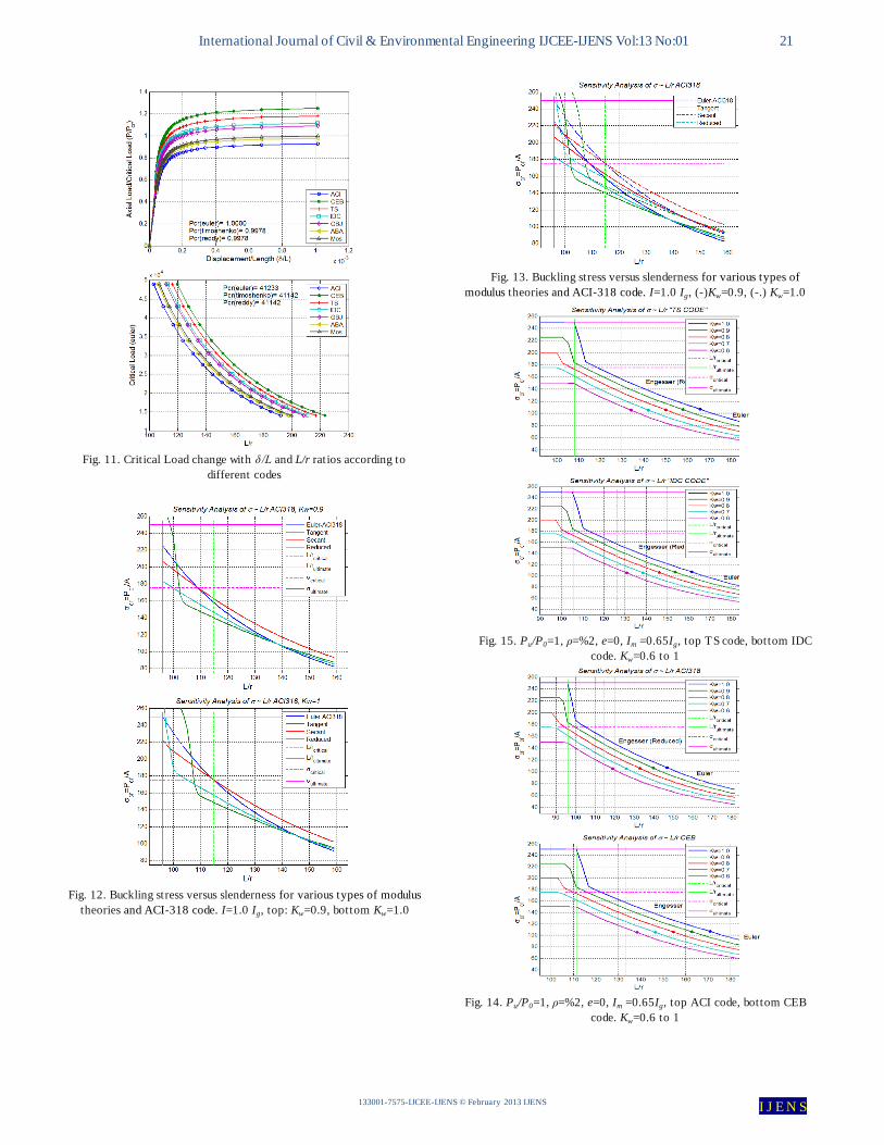
Fig. 11 shows Critical Load change with δ/L and L/r ratios
according to different codes for three types of theories, Euler,
Timoshenko and Reddy. Also comparisons of the results of
the theories are represented in table IV.
IV. INHOMOGENEOUS FORMULATION OF COLUMN BY
THE ENERGY METHOD
Euler's equation is given from solving of a differentiating of
deformation curves and in some parts it is a little complex and
we should use approximation equations based on system
energy. Elasticity modulus, E, is defined by ACI-318 as:
(37)
(38)
Where Wc and Wc0 are the density of concrete and Wcx is
the inhomogeneous formulation of the density.
Inhomogeneous formulations of the compression strength, f’cx,
and elasticity modulus, Ex, are represented as:
(39)
(40)
(41)
(42)
A Pined-pined column section with P load should be
analyzed. In virtual work theorem (spiritual form of original
shape), virtual work, W, equals with strain energy, U, (5, 6). The
actuate form of section is supposed as the first mood and an
element arch length of column is shown by δ or ds, (3). To
calculate accomplished work with external load P, we have
du=ds-dx that equals to displacement of vertical load, (Vahid
Shahsavar, 2011, Krauberger N., 2012), [12,13].
Strain energy of column that relates to flexure
displacement, compressive load and shear force could be
calculated by omission of shear force and for a pined-pined
column section and with (3~6) we can follow the below:
(43)
(44)
(45)
(46)
To create the stress-slenderness sensitivity curves related
to the various codes and various inhomogeneous parameters
(Kw & Kc), the results of the stability analysis were inspected
and collected and the outcome is indicated according to the
related figures. The sensitivity curves were obtained in the
different levels of slenderness and various design codes,
based on the four famous modulus theories, as follows: 1-
Euler, 2- Tangent, 3- Secant, 4- Reduced and the results were
compared.
In fig. 12, buckling stress versus slenderness for various
types of modulus theories and ACI318 code has been
demonstrated, (Left: Kw=0.9, right Kw=1.0). In figs. 13 to 17,
buckling stress versus slenderness for various
inhomogeneous parameters (Kw & Kc) and various design
codes have been demonstrated. Other studied curves and
International Journal of Civil & Environmental Engineering IJCEE-IJENS Vol:13 No:01 18
133001-7575-IJCEE-IJENS © February 2013 IJENS I J E N S
relationships can't be figured in this paper because of some
locative limitations.
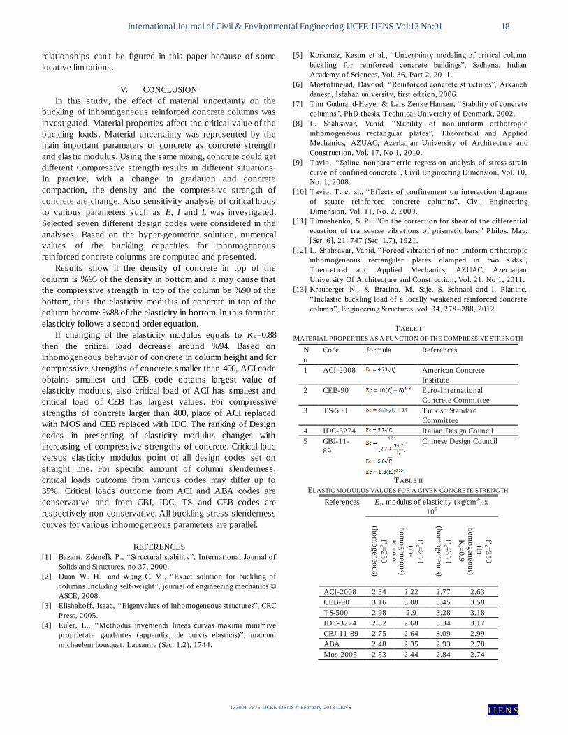
V. CONCLUSION
In this study, the effect of material uncertainty on the
buckling of inhomogeneous reinforced concrete columns was
investigated. Material properties affect the critical value of the
buckling loads. Material uncertainty was represented by the
main important parameters of concrete as concrete strength
and elastic modulus. Using the same mixing, concrete could get
different Compressive strength results in different situations.
In practice, with a change in gradation and concrete
compaction, the density and the compressive strength of
concrete are change. Also sensitivity analysis of critical loads
to various parameters such as E, I and L was investigated.
Selected seven different design codes were considered in the
analyses. Based on the hyper-geometric solution, numerical
values of the buckling capacities for inhomogeneous
reinforced concrete columns are computed and presented.
Results show if the density of concrete in top of the
column is %95 of the density in bottom and it may cause that
the compressive strength in top of the column be %90 of the
bottom, thus the elasticity modulus of concrete in top of the
column become %88 of the elasticity in bottom. In this form the
elasticity follows a second order equation.
If changing of the elasticity modulus equals to KE=0.88
then the critical load decrease around %94. Based on
inhomogeneous behavior of concrete in column height and for
compressive strengths of concrete smaller than 400, ACI code
obtains smallest and CEB code obtains largest value of
elasticity modulus, also critical load of ACI has smallest and
critical load of CEB has largest values. For compressive
strengths of concrete larger than 400, place of ACI replaced
with MOS and CEB replaced with IDC. The ranking of Design
codes in presenting of elasticity modulus changes with
increasing of compressive strengths of concrete. Critical load
versus elasticity modulus point of all design codes set on
straight line. For specific amount of column slenderness,
critical loads outcome from various codes may differ up to
35%. Critical loads outcome from ACI and ABA codes are
conservative and from GBJ, IDC, TS and CEB codes are
respectively non-conservative. All buckling stress-slenderness
curves for various inhomogeneous parameters are parallel.
REFERENCES [1] Bazant, ZdeneÏk P., “Structural stability”, International Journal of
Solids and Structures, no 37, 2000.
[2] Duan W. H. and Wang C. M., “Exact solution for buckling of
columns Including self-weight”, journal of engineering mechanics ©
ASCE, 2008.
[3] Elishakoff, Isaac, “Eigenvalues of inhomogeneous structures”, CRC
Press, 2005.
[4] Euler, L., “Methodus inveniendi lineas curvas maximi minimive
proprietate gaudentes (appendix, de curvis elasticis)”, marcum
michaelem bousquet, Lausanne (Sec. 1.2), 1744.
[5] Korkmaz, Kasim et al., “Uncertainty modeling of critical column
buckling for reinforced concrete buildings”, Sadhana, Indian
Academy of Sciences, Vol. 36, Part 2, 2011.
[6] Mostofinejad, Davood, “Reinforced concrete structures”, Arkaneh
danesh, Isfahan university, first edition, 2006.
[7] Tim Gudmand-Høyer & Lars Zenke Hansen, “Stability of concrete
columns”, PhD thesis, Technical University of Denmark, 2002.
[8] L. Shahsavar, Vahid, “Stability of non-uniform orthotropic
inhomogeneous rectangular plates”, Theoretical and Applied
Mechanics, AZUAC, Azerbaijan University of Architecture and
Construction, Vol. 17, No 1, 2010.
[9] Tavio, “Spline nonparametric regression analysis of stress-strain
curve of confined concrete”, Civil Engineering Dimension, Vol. 10,
No. 1, 2008.
[10] Tavio, T . et al., “Effects of confinement on interaction diagrams
of square reinforced concrete columns”, Civil Engineering
Dimension, Vol. 11, No. 2, 2009.
[11] Timoshenko, S. P., "On the correction for shear of the differential
equation of transverse vibrations of prismatic bars," Philos. Mag.
[Ser. 6], 21: 747 (Sec. 1.7), 1921.
[12] L. Shahsavar, Vahid, “Forced vibration of non-uniform orthotropic
inhomogeneous rectangular plates clamped in two sides”,
Theoretical and Applied Mechanics, AZUAC, Azerbaijan
University Of Architecture and Construction, Vol. 21, No 1, 2011.
[13] Krauberger N., S. Bratina, M. Saje, S. Schnabl and I. Planinc,
“Inelast ic buckling load of a locally weakened reinforced concrete
column”, Engineering Structures, vol. 34, 278–288, 2012.
T ABLE II
ELASTIC MODULUS VALUES FOR A GIVEN CONCRETE STRENGTH
References Ec, modulus of elasticity (kg/cm3) x
105
f’c =
25
0
(ho
mo
gen
eou
s)
f’c =
25
0
(in-
ho
mo
gen
eou
s)
Kc =
0.9
f’c =
35
0
(ho
mo
gen
eou
s)
f’c =
35
0
(in-
ho
mo
gen
eou
s)
Kc =
0.9
ACI-2008 2.34 2.22 2.77 2.63
CEB-90 3.16 3.08 3.45 3.58
TS-500 2.98 2.9 3.28 3.18
IDC-3274 2.82 2.68 3.34 3.17
GBJ-11-89 2.75 2.64 3.09 2.99
ABA 2.48 2.35 2.93 2.78
Mos-2005 2.53 2.44 2.84 2.74
T ABLE I
MATERIAL PROPERTIES AS A FUNCTION OF THE COMPRESSIVE STRENGTH
N
o
Code formula References
1 ACI-2008 American Concrete
Institute
2 CEB-90 Euro-International
Concrete Committee
3 TS-500 Turkish Standard
Committee
4 IDC-3274 Italian Design Council
5 GBJ-11-
89
Chinese Design Council
International Journal of Civil & Environmental Engineering IJCEE-IJENS Vol:13 No:01 19
133001-7575-IJCEE-IJENS © February 2013 IJENS I J E N S
Fig. 1. Stress-strain curves, top: general, botton: Todeschini
Fig. 4. Sensitivity analysis of Ec with Wc or f’c according to column
nonparametric height (top: Kw=0.95, bottom: Kc=0.90)
Fig. 3. Sensitivity analysis of Ec with Wc and f’c according to different
Kw and Kc ratios
Fig. 2. A: Todeschini model, B: Hognestad model, s: secant modulus, t :
tangent modulus, r: reduced modulus of elasticity
T ABLE IV
CRITICAL LOADS VALUES FOR VARIOUS REFERENCES
References
Pcr, (ton)
Euler
(equation)
Kw=1
Timoshenk
o
(equation)
Kw=1
ACI-2008 39 38.92
CEB-90 52.65 52.53
TS-500 49.67 49.56
IDC-3274 47 46.9
GBJ-11-89 45.86 45.76
ABA 41.23 41.14
Mos-2005 42.11 42.02
T ABLE III
DEFINITION OF CT BASED ON CROSS SECTION SHAPE AND NUMBER OF
BARS
Shape
Number of bars 8 12 16

International Journal of Civil & Environmental Engineering IJCEE-IJENS Vol:13 No:01 20
133001-7575-IJCEE-IJENS © February 2013 IJENS I J E N S
Fig. 10. Elastic modulus change with critical load according
to different codes, (top Kw=1, bottom Kw=0.8)
Fig. 9. EImm according to different reinforcement ratios (βd=0,
Ct=2.2, ACI318)
Fig. 8. Cracked moments of inertia of compression and flexural
members according to different reinforcement ratios, top e=0, Mu=0,
bottom e=%5, Mu=0.05*h*Pu
Fig. 7. Relationship curves of elasticity modulus and various
concrete strengths for different design codes, top: Kc=0.9, bottom:
Kc=0.6 [Kc=f’c/f’c0]
Fig. 6. Relationship curves of elasticity Modulus and various concrete
strengths for different design codes, Kc=1
Fig. 5. Sensitivity analysis of Ec with Wc and f’c according to column
nonparametric height (Kw=0.95 & Kc=0.90)
International Journal of Civil & Environmental Engineering IJCEE-IJENS Vol:13 No:01 21
133001-7575-IJCEE-IJENS © February 2013 IJENS I J E N S
Fig. 15. Pu/P0=1, ρ=%2, e=0, Im =0.65Ig, top TS code, bottom IDC
code. Kw=0.6 to 1
Fig. 14. Pu/P0=1, ρ=%2, e=0, Im =0.65Ig, top ACI code, bottom CEB
code. Kw=0.6 to 1
Fig. 13. Buckling stress versus slenderness for various types of
modulus theories and ACI-318 code. I=1.0 Ig, (-)Kw=0.9, (-.) Kw=1.0
Fig. 12. Buckling stress versus slenderness for various types of modulus
theories and ACI-318 code. I=1.0 Ig, top: Kw=0.9, bottom Kw=1.0
Fig. 11. Critical Load change with δ/L and L/r ratios according to
different codes
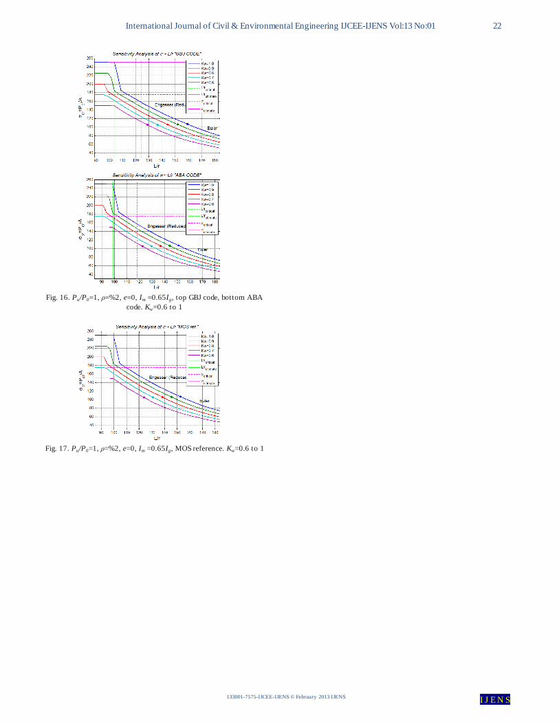
International Journal of Civil & Environmental Engineering IJCEE-IJENS Vol:13 No:01 22
133001-7575-IJCEE-IJENS © February 2013 IJENS I J E N S
Fig. 17. Pu/P0=1, ρ=%2, e=0, Im =0.65Ig, MOS reference. Kw=0.6 to 1
Fig. 16. Pu/P0=1, ρ=%2, e=0, Im =0.65Ig, top GBJ code, bottom ABA
code. Kw=0.6 to 1