senior capstone project proposal -...
TRANSCRIPT
Senior Capstone Project ProposalElectronic Warfare Digital Radar Receiver
Project MembersMichael GahlPeter Petrany
Project AdvisorsDr. In Soo Ahn
Dr. Brian HugginsMr. James Jensen
Bradley UniversityDepartment of Electrical & Computer Engineering
EE 451 – Senior LaboratoryDecember 9, 2004

Table of Contents
Table of Images………………………………………………………………………………….. 3Functional Description………………………………………………………………………….. 4 - 5System Block Diagram Deliverable……………………………………………………………. 6 - 11Mathematical Computations…………………………………………………………………… 12 - 14Simulation Results………………………………………………………………………………. 15 - 16Standards………………………………………………………………………………………… 17Patents & Patent Applications……………………………………………….………………… 17Datasheet………………………………………………………………………………………… 18Schedule………………………………………………………………………………………….. 19Equipment List………………………………………………………………………………….. 20References…………………………………………………………………………………….…. 21Appendix 1 - Abstracts…………………………………………………………….…………….. 22 - 24Appendix 2 - Code……………………………………………………………………………….. 25 - 26
Dec. 9, 2004 Electronic Warfare Digital Radar ReceiverBradley University, ECE Department
2

Table of Images
Figure 1: EW Digital Radar Receiver…………………………………………………………………... 4Figure 2: RF Signal Parameters……………………………………………………………………….. 5Figure 3: Top-Level Block Diagram…………………………………………………………………… 6Figure 4: Sub-Level Block Diagram…………………………………………………………………… 7Figure 5: Block 1: RF Front End…………………………………………………………….………… 7Figure 6: Block 2: PLL (Frequency Synthesizer)………………………………………………………… 8Figure 7: Block 3: Data Acquisition Card…………………………………………………….………… 8Figure 8: Block 4: DSP and Display…………………………………………………………………… 8Figure 9: DSP Technique Flowchart………………………………………………………………….... 9Figure 10: Calculate RF Signal Characteristics Flowchart………………………………………………… 10Figure 11: Is Signal Detected Flowchart………………………………………………………………... 11Figure 12: Time Domain Waveforms………………………………………………………………….. 12Figure 13: Frequency Domain Waveform…………………………………………………….………… 14Figure 14: Simulink Model with Time Domain Waveforms………………………………………………. 15Figure 15: Matlab FFT Plot of Pulsed Radar Signal……………………………………………………… 16Figure 16: Datasheet Specifications……………………………………………………………………. 18A2.1: Matlab Code to Perform FFT on Pulsed Radar Signal……………………………………………….. 25A2.2: Matlab Code to Determine RF Signal Characteristics from FFT of A2.1……………………………….. 26
Dec. 9, 2004 Electronic Warfare Digital Radar ReceiverBradley University, ECE Department
3

Functional Description
IntroductionIn electronic warfare (EW), it is beneficial to classify radio frequency (RF) signals to identify and/or jaman enemy’s use of the electromagnetic spectrum. Characterization of a RF signal can be achieved throughthe use of an EW digital radar receiver. This project will focus on the identification and characterizationof a pulsed radar signal.
Project DescriptionAn EW digital radar receiver is of interest to Northrop Grumman Corporation (NGC), and the project isproposed by Mr. James Jensen, RF Technology Manager, Northrop Grumman Electronic Systems,Defensive Systems Division. From information provided by NGC, the digital radar receiver shown inFigure 1 will be simulated, designed, and implemented.
Computer
DataAcquisition
Card
Digital SignalProcessing
(DS P)LNARF
SignalMo n i to r
Processing ControlCommands
f RF
PWPRRNo Signal Detected
CNTRL
LO
(Fre qu e n cyS y n th e s i z e r)
Mi x e r
Lo w-No i s eA m pl i f i e r
IF
Fi l te r Fi l te r
PLL
Figure 1: EW Digital Radar Receiver
System DescriptionThere is only one mode of operation for the EW digital radar receiver: operational mode. Other modescould be implemented, such as calibration and maintenance modes, but are not, for the scope of thisproject. A range of RF signals is generated using a RF signal generator. Then the EW digital radarreceiver determines the signal characteristics of the pulsed RF signal.
Dec. 9, 2004 Electronic Warfare Digital Radar ReceiverBradley University, ECE Department
4

System Inputs & OutputsInputs to the EW digital radar receiver are a RF signal and processing control commands, as shown inFigure 1. Possible processing control commands are selecting the local oscillator (LO) frequency andaveraging to recover the signal in a noisy environment. There are four system outputs from the EW digitalradar receiver. The pulse repetition rate (PRR [pulses per second]) is the inverse of the period of theenvelope of the RF signal, the pulse width (PW [μs]) is the time duration that the RF signal is presentunder the envelope and fRF [GHz] is the frequency of the signal during the PW. These are shown in Figure2. Lastly, there is a signal that indicates if a signal has been detected.
Figure 2: RF Signal Parameters
Dec. 9, 2004 Electronic Warfare Digital Radar ReceiverBradley University, ECE Department
5

System Block Diagram Deliverable
Top Level Block DiagramInputs to the EW digital radar receiver are a RF signal and processing control commands as shown inFigure 3. Possible processing control commands are selecting the local oscillator (LO) frequency andaveraging to recover the signal in a noisy environment. There are four system outputs from the EW digitalradar receiver. The outputs are the following and shown in Figure 2 and Figure 3:
• Pulse Repetition Rate (PRR) - the inverse of the period of the RF signal’s envelope
• Pulse Width (PW) - the time duration that the RF signal is present under the envelope
• RF signal’s frequency (fRF) - the frequency of the signal during the PW
• No Signal Detected - the presence of a signal is not detected by computer algorithm
Figure 3: Top-Level Block Diagram
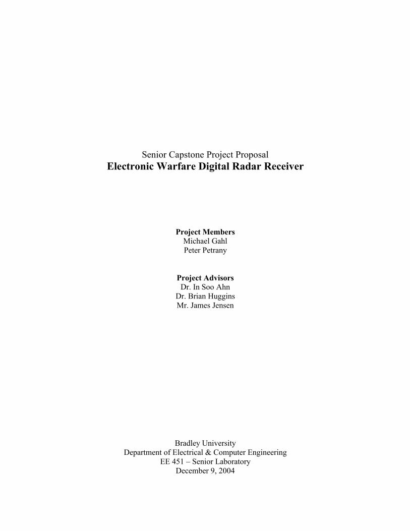
Sub-Level Block DiagramThe sub-level block diagram shown in Figure 4 displays the EW digital radar receiver in more detail thanFigure 3. Block 1 mixes an analog RF signal with an analog LO frequency from Block 2 to produce ananalog intermediate frequency (IF). The IF signal is sampled by Block 3 to be processed by Block 4. Inaddition, Block 4 controls the LO frequency transmitted by Block 2 through a feedback path (CNTRL). An option is to have the user set the LO frequency by configuring CNTRL to be a user input.
Dec. 9, 2004 Electronic Warfare Digital Radar ReceiverBradley University, ECE Department
6
Computer
DataAcquisition
Card
Digital SignalProcessing
(DS P)LNA
RFSignal
Mo n i to r
Processing ControlCommands
f RF
PWPRRNo Signal Detected
CNTRL
LO
(Fre qu e n cyS y n th e s i z e r)
Mi x e r
Lo w -N o i s eA m pl i f i e r
IF
Fi l te r Fi l te r
Block 1Block 3
Block 2
Block 4
PLL
Figure 4: Sub-Level Block Diagram
Block 1: RF Front EndA RF signal is input into the RF front end as shown in Figure 5. In lab, a signal generator produces theRF signal, but in application, an antenna would be used to receive the signal. The signal is amplified in alow-noise amplifier (LNA) to increase the power of the input signal. The bandpass filter following theLNA requires a bandwidth (BW) covering the range of the RF signal and attenuates noise outside thisrange. Next, the mixer multiplies the amplified RF signal with the LO frequency from Block 2. Becausethe mixer output consists of many frequencies, another bandpass filter must be implemented into the sub-system to attenuate all frequency components other than the desired IF.
LNA
RFSignal
LO
Mi x e r
Lo w-No i s eA m pl i fi e r
Fi l te r Fi l te r
SignalGenerator
IF
Figure 5: Block 1: RF Front End
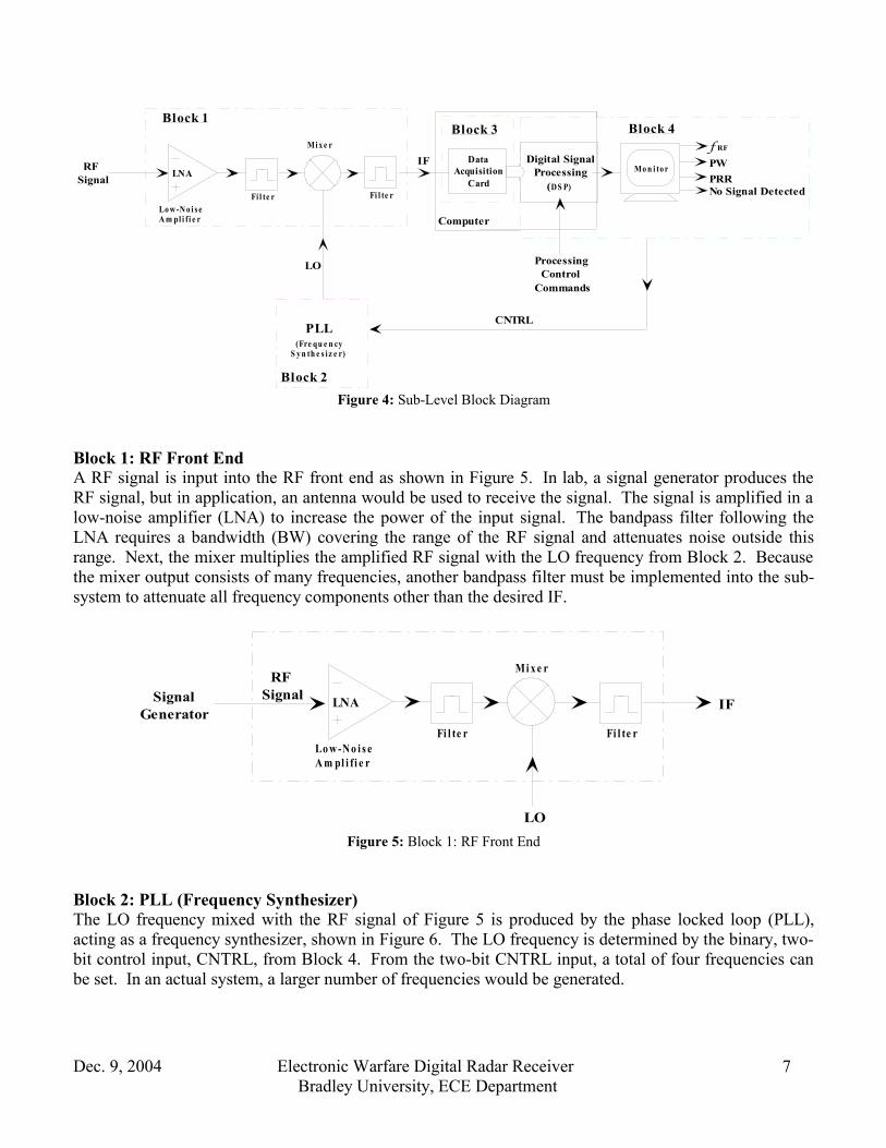
Block 2: PLL (Frequency Synthesizer)The LO frequency mixed with the RF signal of Figure 5 is produced by the phase locked loop (PLL),acting as a frequency synthesizer, shown in Figure 6. The LO frequency is determined by the binary, two-bit control input, CNTRL, from Block 4. From the two-bit CNTRL input, a total of four frequencies canbe set. In an actual system, a larger number of frequencies would be generated.
Dec. 9, 2004 Electronic Warfare Digital Radar ReceiverBradley University, ECE Department
7
CNTRL LO (Fre qu e n cyS y n th e s i z e r)
PLL
Figure 6: Block 2: PLL (Frequency Synthesizer)
Block 3: Data Acquisition CardThe IF signal of Block 1 is sampled by the data acquisition card in Block 3 as shown in Figure 7. On-board the data acquisition card is an analog-to-digital converter (ADC), which converts the IF signal into abinary data stream. The binary data is output from Block 3.
DataAcquisition
Card IF
Binary DataStream
Figure 7: Block 3: Data Acquisition Card
Block 4: DSP and DisplayThe binary data stream from Block 3 is stored into memory so that digital signal processing (DSP) withinMATLAB can perform calculations on the data as shown in Figure 8. Based on the detection of a RFsignal, and the DSP calculations, fRF, the PW, and the PRR are displayed. If no signal is detected, CNTRLinstructs the PLL to change the LO frequency, and “no signal present” is displayed on the monitor. Also,processing control commands input into Block 4 determine the LO frequency and averaging of the IFsignal.
Digital SignalProcessing
(D S P)
Binary DataStream
f RF
PWPRRNo Signal Detected
Processing ControlCommands
CNTRL
Monitor
Figure 8: Block 4: DSP and Display
Dec. 9, 2004 Electronic Warfare Digital Radar ReceiverBradley University, ECE Department
8

Flowchart: DSP TechniqueThe flowchart shown in Figure 9 shows the technique for calculating the characteristics of the input RFsignal. The IF signal sampled, see Figure 1, is digitized by the ADC and the computer performs the FFTon the sampled data. The user can define the LO frequency by specifying CNTRL before taking the FFT. Following the FFT, the RF signal characteristics are calculated, and examined in more detail in Figure 10.Next, it is determined if a signal is present at the input of the computer. The process for determining thepresence of a signal is shown in Figure 11. If the signal has been detected, the RF signal characteristicsare displayed, otherwise, the LO frequency is incremented and “No Signal Detected” is displayed.
ADC Samples
FFT
Calculate RF Signal
Characteristics
Is signal detected?
Display fRF, PW, PRR
Increment LO
Specify CNTRL
Yes
No
Figure 9: DSP Technique Flowchart
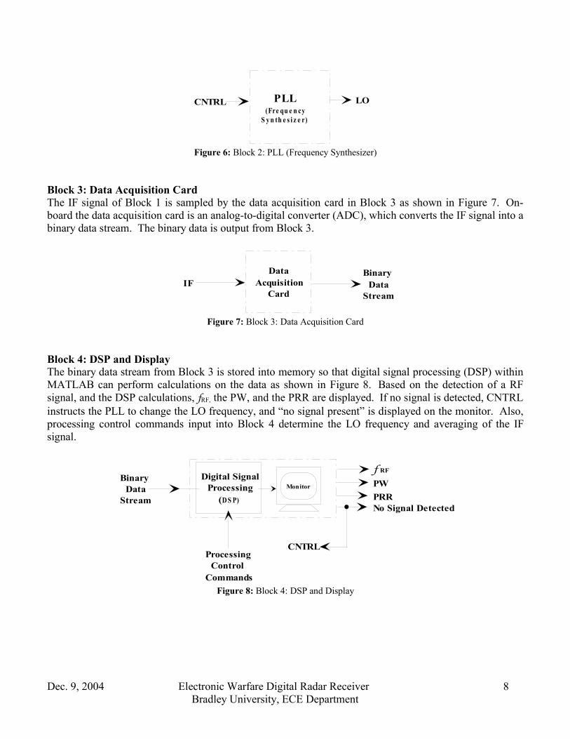
Figure 10 shows the flowchart for the expansion of the RF signal characteristics calculation block ofFigure 9. Following the FFT operation on the input IF signal, the RF signal characteristics are found.Figure 10a-c shows characteristics used to find the PRR, PW, and fRF. First, fIF is determined by findingthe frequency that corresponds to the maximum value of the FFT data. From the subsequent peak at f1, thePRR can be calculated. Next, to find the PW, f0, the zero-crossing closest to fIF, is required. f0 can befound by checking the FFT data for a sign change in slope. The slope changes at zero-crossings, inaddition, at local minimums and maximums. Lastly, fRF can be calculated by adding the LO frequency tofIF. Once the RF signal characteristics have been found, the presence of a signal can be determined, whichis shown in Figure 11.
Dec. 9, 2004 Electronic Warfare Digital Radar ReceiverBradley University, ECE Department
9
Find frequency at peak magnitude = fIF
(see figure a)
Find frequency of subsequent peak = f1
(see figure b)
|f1 – fIF| = 1/T = PRR
Find frequency at nearest zero crossing = fIF + f01
(see figure c)
|f0 – fΙF| = 1/τ = 1/PW
FFT
Is Signal Detected
LO + fIF = fRF
Figure 10: Calculate RF Signal Characteristics Flowchart
Dec. 9, 2004 Electronic Warfare Digital Radar ReceiverBradley University, ECE Department
10

Figure 11 describes the process to determine if a valid radar signal has been detected at the input of thecomputer. Initially, software determines whether the maximum magnitude of the signal is above athreshold value, specified in code. The threshold value is greater than the magnitude contributed by noise.If a signal above the threshold value is detected, a second check is applied to verify that a valid radarsignal is detected. The second criterion is that the zero-crossings surrounding both sides of fIF need to beequal, within a certain percentage, which is specified in code. If both of these conditions are met, a validRF signal has been detected at the computer’s input and the software can display the calculated RF signalcharacteristics. If either of the conditions are not met, “No Signal Detected” is displayed and the LOfrequency is incremented. The process continues by taking the FFT of the input data over the newfrequency range.
Decision
Signal has been detected
No signal detected
Is m a x i m u m p e a k ≥
threshold?
Is |fIF + f01| = | fIF - f02 |
?
Display Characteristics
No
Yes
Yes
No
Increment LO
Display “No Signal Detected”
Figure 11: Is Signal Detected Flowchart
Dec. 9, 2004 Electronic Warfare Digital Radar ReceiverBradley University, ECE Department
11

Mathematical Computation
The following shows the mathematical computations, which are implemented in MATLAB, to solve forthe RF signal characteristics of the input waveform. Waveform (1) shows the input RF signal, (2) is thepulse envelope, which dictates the on-time of the RF signal, and (3) is created by mixing waveform (1)and (2) together. Waveform (3) is the pulsed RF signal that is used to find the characteristics of the inputRF signal.
Figure 12: Time Domain Waveforms
The pulse width (PW = τ), pulse repetition rate (PRR = T1 ), and the RF frequency (fRF) can be easily
calculated by taking the Fast Fourier Transform (F ) of waveform (3).
Derivation
( )2
2 2 2cos)(w
TfjeTfj
eTftRFRF
RF
πππ
−+==
∑ −Π=
n
nTttpτ
)( , where τ is the width of the rectangular pulse, and T is the repetition period
Dec. 9, 2004 Electronic Warfare Digital Radar ReceiverBradley University, ECE Department
12

Table 2-1 , multiplication in the time domain , convolution in the frequency domain
Table 2-2
( ) ( ) ( )RFRF fffftFf ++−== δδ 21
21)(w)W(
Table 2-2( ) ( ) fnTjefSatpFfP
n
πτπτ 2 )()( −∑== , fnTje π2− accounts for the pulse train time delay
Equation 3-38: Poisson Sum Formula
∑ −=∑∞
−∞=
∞
−∞=
nn TnfT
fnTje δπ 12
( ) ( ) ∑ −+++∑ −−−=∞
−∞=
∞
−∞=
nRFRF
nRFRF T
nffTffSaTnffTffSafS )(1)( 2
1)(1)( 21)( δτπτδτπτ
Dec. 9, 2004 Electronic Warfare Digital Radar ReceiverBradley University, ECE Department
13
( ) ( )[ ] ( )
( ) ( ) ( ) ( )
( ) ( )
( ) ( )∑ +−++∑−−−=
∑+−++−−−=
∑ −++−−=
−∑∗++−=
∗=
n
RFRFn
RFRF
n
RFRFRFRF
nRFRF
nRFRF
nTffjeffSanTffjeffSa
nTffjeffSanTffjeffSa
fnTjefSafffnTjefSaff
fnTjefSafffffS
fPffS
)(2)( 21)(2)( 2
1
)(2)( )(2)( 21
2 *2 *21
2 21 )(
)( )W( )(
πτπτπτπτ
πτπτπτπτ
πτπτδπτπτδ
πτπτδδ
FFF
)( )( w )( tptts ⋅=
)()W()( fPffS ∗=

Figure 13: Frequency Domain Waveform
Note: Zero crossings are at ττ 1 1)( +=⇒=− RFRF ffff
The envelope of the sinc function, ( )τπ )( RFffSa − , determines the magnitudes of the spectral
components at frequencies τnfRF + . As illustrated in Figure 13, the PRR, PW, and fRF can be easily
determined.
Note: All tables and equations for the Mathematical Computation section of the Project Proposal are from Reference 4.
Dec. 9, 2004 Electronic Warfare Digital Radar ReceiverBradley University, ECE Department
14
Simulation Results
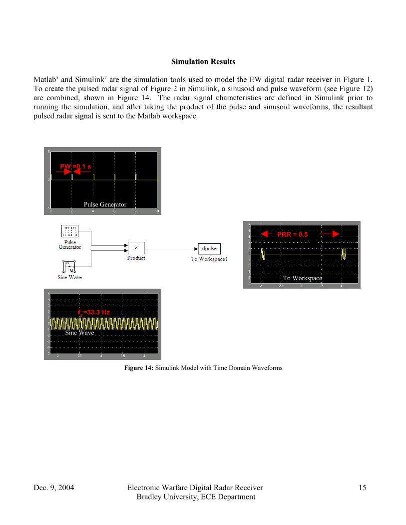
Matlab5 and Simulink7 are the simulation tools used to model the EW digital radar receiver in Figure 1.To create the pulsed radar signal of Figure 2 in Simulink, a sinusoid and pulse waveform (see Figure 12)are combined, shown in Figure 14. The radar signal characteristics are defined in Simulink prior torunning the simulation, and after taking the product of the pulse and sinusoid waveforms, the resultantpulsed radar signal is sent to the Matlab workspace.
Figure 14: Simulink Model with Time Domain Waveforms
Dec. 9, 2004 Electronic Warfare Digital Radar ReceiverBradley University, ECE Department
15
To Workspace
fIF=33.3 Hz
Pulse Generator
PW =0.1 s
PRR = 0.5 s
Sine Wave

The Matlab m-files in Appendix 2, A2.1 and A2.2, follow the flowchart specified in Figure 9, to performthe FFT on the pulsed radar signal to extract the input RF signal characteristics. Figure 15 shows theresulting plots after the m-file simulation is executed. From these plots, the three desired parameters areeasily extracted.
Dec. 9, 2004 Electronic Warfare Digital Radar ReceiverBradley University, ECE Department
16
Figure 15: Matlab FFT Plot of Pulsed Radar Signal
PW = 0.1 s
fIF = 33.33 Hz
PRR = 0.5 s
zoomed out

Standards
Radar Types1
Pulse Type Radar 1% duty cycle 200μs - 2ms envelope periodPulse Doppler 30 - 40% duty cycle 10μs envelope period
Standard Radar Types from Reference 3
Dec. 9, 2004 Electronic Warfare Digital Radar ReceiverBradley University, ECE Department
Patents & Patent Applications
Patents3,982,244 Radar Antenna, Monopulse Comparator Network and Mixer Simulator1
4,666,407 Radar Signature Simulator2
4,959,015 System and Simulator for In-flight Threat and Countermeasures3 Training5,475,391 Radar Receiver4
6,693,578 Mixer Optimization for Active Radar Warning Receiver5
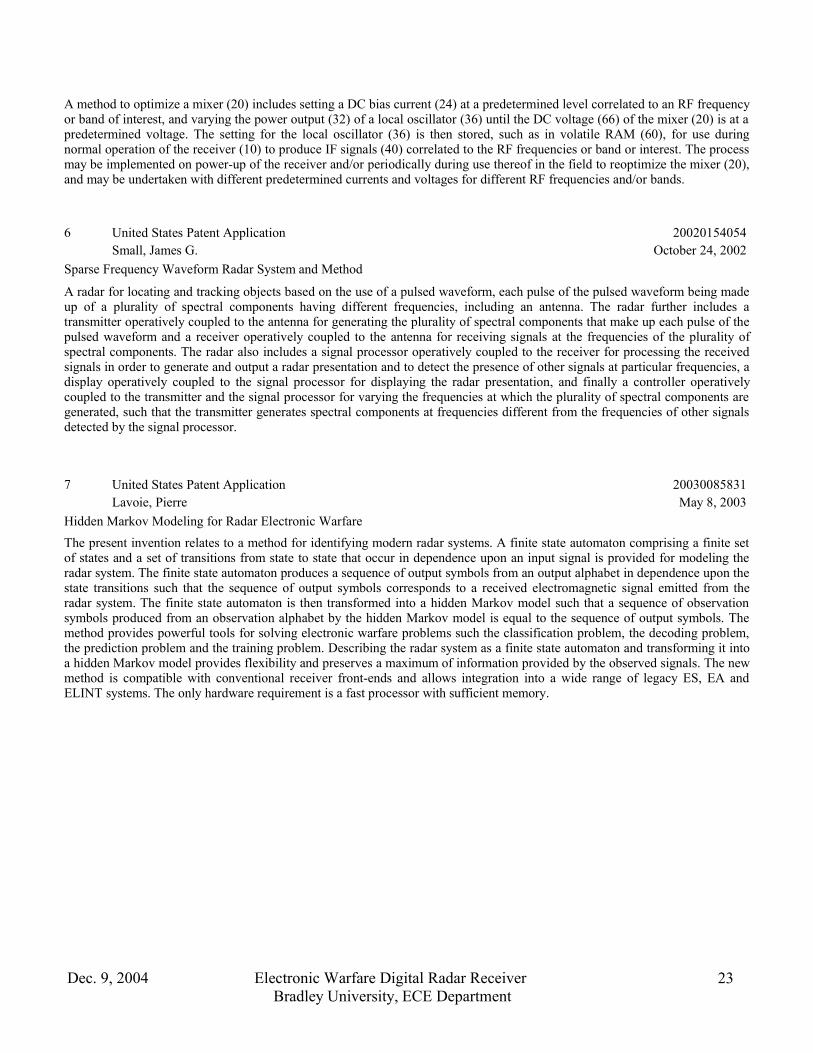
Patent Applications20020154054 Sparse Frequency Waveform Radar System and Method6
20030085831 Hidden Markov Modeling for Radar Electronic Warfare7
20030193430 Pulse Radar Detection System8
20040212358 Scanning RF Receiver9
20040234001 Adaptive Radio Frequency (RF) Filter10
See Appendix 1 for AbstractAll patents and patent applications searched for on <www.uspto.gov> website.
17
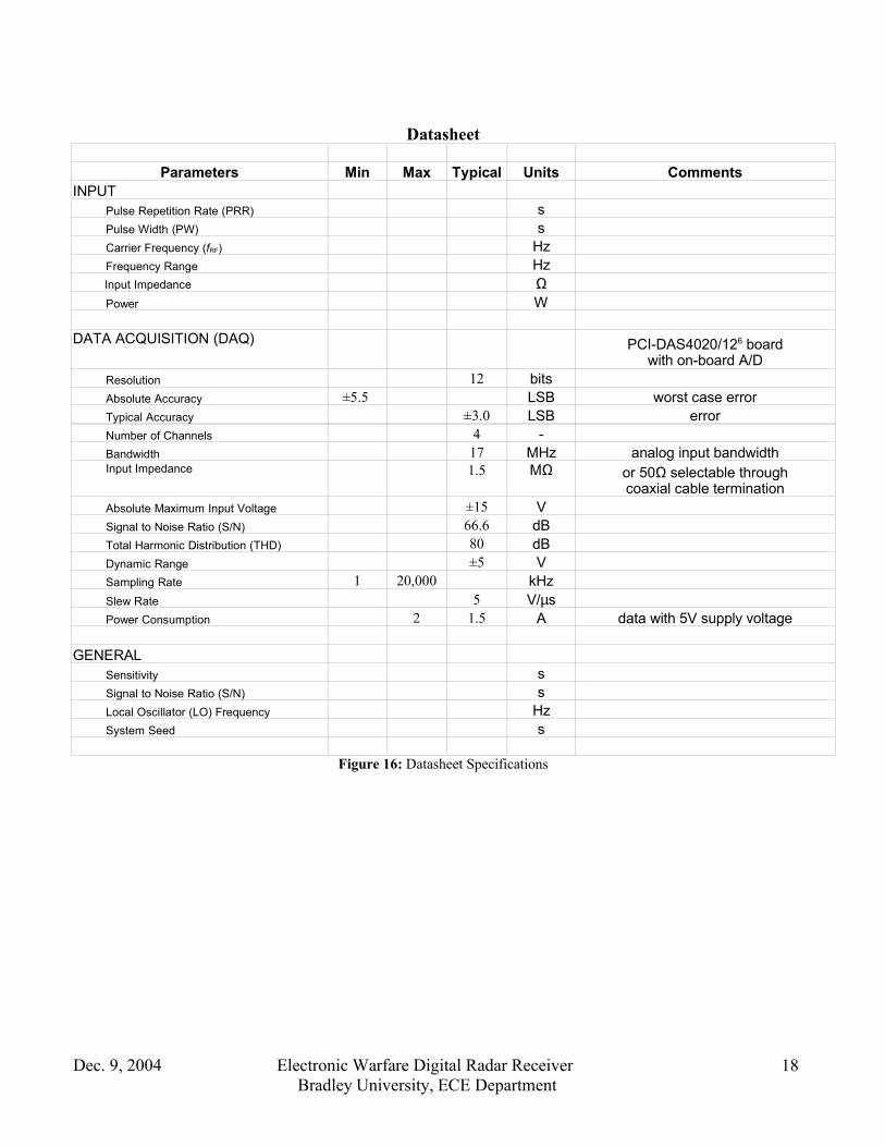
Datasheet
Parameters Min Max Typical Units CommentsINPUT Pulse Repetition Rate (PRR) s Pulse Width (PW) s Carrier Frequency (fRF) Hz Frequency Range Hz Input Impedance Ω Power W
DATA ACQUISITION (DAQ) PCI-DAS4020/126 boardwith on-board A/D
Resolution 12 bits Absolute Accuracy ±5.5 LSB worst case error Typical Accuracy ±3.0 LSB error Number of Channels 4 - Bandwidth 17 MHz analog input bandwidth Input Impedance 1.5 MΩ or 50Ω selectable through
coaxial cable termination Absolute Maximum Input Voltage ±15 V Signal to Noise Ratio (S/N) 66.6 dB Total Harmonic Distribution (THD) 80 dB Dynamic Range ±5 V Sampling Rate 1 20,000 kHz Slew Rate 5 V/µs Power Consumption 2 1.5 A data with 5V supply voltage GENERAL Sensitivity s Signal to Noise Ratio (S/N) s Local Oscillator (LO) Frequency Hz System Seed s
Figure 16: Datasheet Specifications
Dec. 9, 2004 Electronic Warfare Digital Radar ReceiverBradley University, ECE Department
18
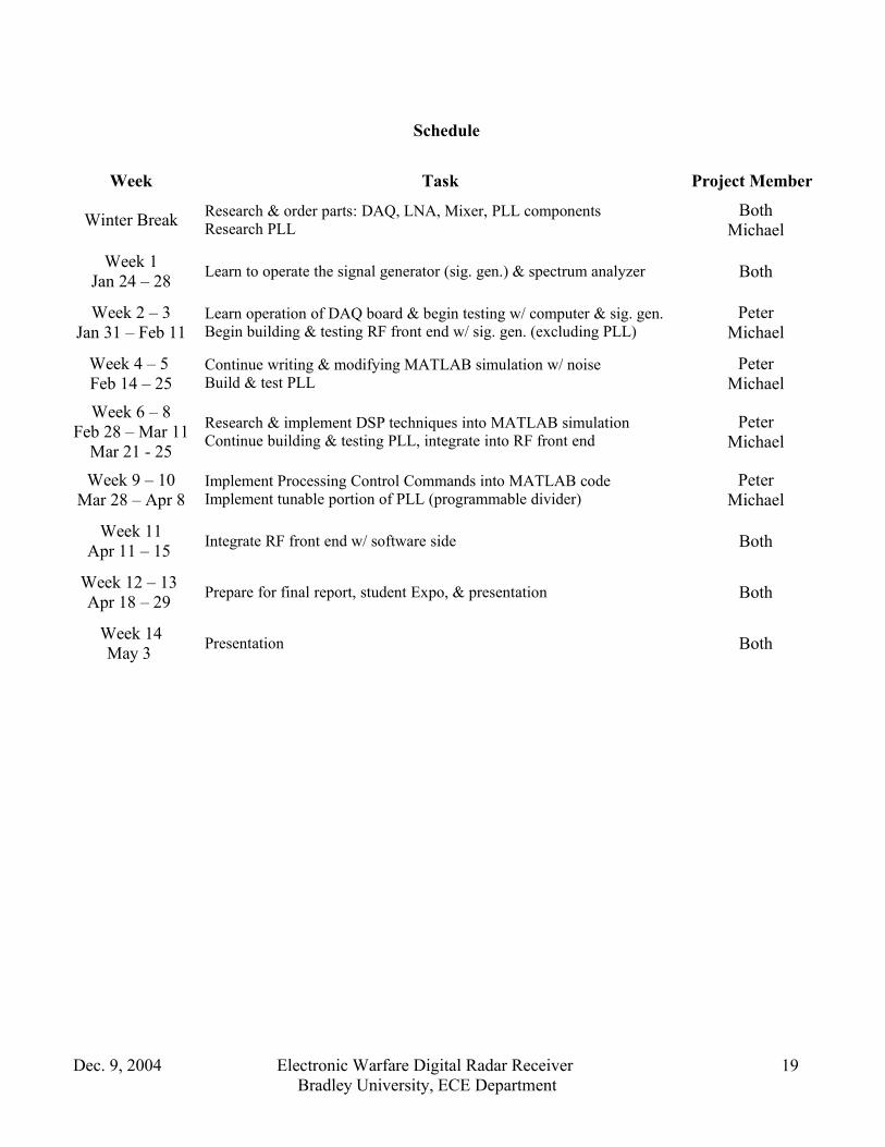
Schedule
Week Task Project Member
Winter Break Research & order parts: DAQ, LNA, Mixer, PLL componentsResearch PLL
BothMichael
Week 1Jan 24 – 28 Learn to operate the signal generator (sig. gen.) & spectrum analyzer Both
Week 2 – 3Jan 31 – Feb 11
Learn operation of DAQ board & begin testing w/ computer & sig. gen.Begin building & testing RF front end w/ sig. gen. (excluding PLL)
PeterMichael
Week 4 – 5 Feb 14 – 25
Continue writing & modifying MATLAB simulation w/ noiseBuild & test PLL
PeterMichael
Week 6 – 8Feb 28 – Mar 11
Mar 21 - 25
Research & implement DSP techniques into MATLAB simulationContinue building & testing PLL, integrate into RF front end
PeterMichael
Week 9 – 10Mar 28 – Apr 8
Implement Processing Control Commands into MATLAB codeImplement tunable portion of PLL (programmable divider)
PeterMichael
Week 11Apr 11 – 15 Integrate RF front end w/ software side Both
Week 12 – 13 Apr 18 – 29 Prepare for final report, student Expo, & presentation Both
Week 14May 3 Presentation Both
Dec. 9, 2004 Electronic Warfare Digital Radar ReceiverBradley University, ECE Department
19
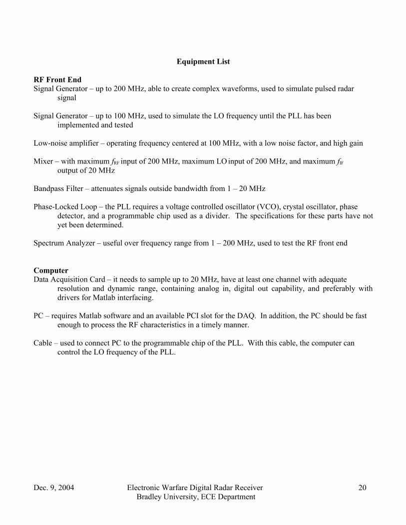
Equipment List
RF Front EndSignal Generator – up to 200 MHz, able to create complex waveforms, used to simulate pulsed radar
signal
Signal Generator – up to 100 MHz, used to simulate the LO frequency until the PLL has been implemented and tested
Low-noise amplifier – operating frequency centered at 100 MHz, with a low noise factor, and high gain
Mixer – with maximum fRF input of 200 MHz, maximum LO input of 200 MHz, and maximum fIF
output of 20 MHz
Bandpass Filter – attenuates signals outside bandwidth from 1 – 20 MHz
Phase-Locked Loop – the PLL requires a voltage controlled oscillator (VCO), crystal oscillator, phase detector, and a programmable chip used as a divider. The specifications for these parts have notyet been determined.
Spectrum Analyzer – useful over frequency range from 1 – 200 MHz, used to test the RF front end
ComputerData Acquisition Card – it needs to sample up to 20 MHz, have at least one channel with adequate
resolution and dynamic range, containing analog in, digital out capability, and preferably withdrivers for Matlab interfacing.
PC – requires Matlab software and an available PCI slot for the DAQ. In addition, the PC should be fast enough to process the RF characteristics in a timely manner.
Cable – used to connect PC to the programmable chip of the PLL. With this cable, the computer can control the LO frequency of the PLL.
Dec. 9, 2004 Electronic Warfare Digital Radar ReceiverBradley University, ECE Department
20
References
1 James Bao-yen Tsui, Digital Microwave Receviers (Artech House, Inc. 1989).
2 James Bao-yen Tsui, Microwave Receivers with Electronic Warfare Applications (New York: John Wiley and Sons, Inc. 1986).
3 Jim Jensen, interview by Michael Gahl, Bradley University, 5 November 2004.
4 Leon W. Couch, II, Digital And Analog Communication Systems, 6th edition (New Jersey: Prentice-Hall, Inc. 1997), 50-62.
5 Matlab 6.5.0.180913a Release 13 [Computer software]. The MathWorks, Inc. June 2002.
6 Measurement Computing. 06 Dec. 2004. <http://measurementcomputing.com>.
7 Simulink 5.0 Release 13 [Computer software]. The MathWorks, Inc. June 2002.
Dec. 9, 2004 Electronic Warfare Digital Radar ReceiverBradley University, ECE Department
21

Appendix 1 - Abstracts1 United States Patent 3,982,244
Ward , et al. September 21, 1976Radar Antenna, Monopulse Comparator Network and Mixer SimulatorThe radar antenna, monopulse comparator network, and mixer simulator is a al-time computer controlled simulation of theantenna, monopulse comparator network, and rf mixer of tracking radar systems which normally transform the angle of arrival ofincoming signals into amplitude and phase modulations on intermediate frequency sum and difference channel signals. Thesimulator produces appropriately modulated intermediate frequency (IF) sum and difference channel signals as a function ofcomputer derived spatial angle information. These IF signals correspond to the radar-hardware-derived sum and differencechannel IF signals.
2 United States Patent 4,666,407 Jones May 19, 1987
Radar Signature SimulatorSystem and method for producing a pattern of radar radiation encountered by a object in the scan path of a radar, commonlyreferred to as "radar signature". The basic system has a memory containing at least digital amplitude information for each pulseof the signature, digital pulse width information for each pulse, digital pulse-to-pulse interval information for each pulse, scantime information and scan gap information. A digital to analog converter converts the digital amplitude information to aproportional voltage. Timers convert the pulse width information, the pulse-to-pulse interval information, scan time informationand scan gap information to intervals of time in sequential fashion. During pulse width times, the output of the digital to analogconverter is enabled. The output is disabled during pulse-to-pulse intervals and scan gap time. A controller controls the transferof amplitude information from memory to the digital to analog converter and controls operation of the timers. The output of thedigital to analog converter is a train of pulses of varying amplitudes. The output of the digital to analog converter can be sentdirectly to an intercept receiver or it can be mixed with an RF carrier wave to create a more accurate simulation of the radarsignature. A computer responsive to an operator enables an operator to select a radar scenario, and based on the selectedscenario, transfers amplitude and time information to the memory for use by the controller.
3 United States Patent 4,959,015 Rasinski , et al. September 25, 1990
System and Simulator for In-flight Threat and CountermeasuresAn interactive trainer for electronic countermeasures simulation capable of providing displays of in-flight threats andcountermeasures responses representative of an actual combat equipment suite. Threat scenarios are stored in computer memoryand recalled at a push-button display console. Default parameters may readily be modified by the operator under softwarecontrol. The aircraft position with respect to selected threats is displayed in real time superposed on the threat parameters.Displays are identical to that provided by the equipment simulated and reflect the true operational status as preset by theoperator.
4 United States Patent 5,475,391 Spencer December 12, 1995
Radar ReceiverA narrow band receiver is shown to include a double downconversion arrangement wherein the frequency of the second localoscillator is controlled to maintain the frequency of the second I.F. signals at a predetermined value.5 United States Patent 6,693,578
Martinson February 17, 2004 Mixer Optimization for Active Radar Warning Receiver
Dec. 9, 2004 Electronic Warfare Digital Radar ReceiverBradley University, ECE Department
22
A method to optimize a mixer (20) includes setting a DC bias current (24) at a predetermined level correlated to an RF frequencyor band of interest, and varying the power output (32) of a local oscillator (36) until the DC voltage (66) of the mixer (20) is at apredetermined voltage. The setting for the local oscillator (36) is then stored, such as in volatile RAM (60), for use duringnormal operation of the receiver (10) to produce IF signals (40) correlated to the RF frequencies or band or interest. The processmay be implemented on power-up of the receiver and/or periodically during use thereof in the field to reoptimize the mixer (20),and may be undertaken with different predetermined currents and voltages for different RF frequencies and/or bands.
6 United States Patent Application 20020154054 Small, James G. October 24, 2002
Sparse Frequency Waveform Radar System and Method
A radar for locating and tracking objects based on the use of a pulsed waveform, each pulse of the pulsed waveform being madeup of a plurality of spectral components having different frequencies, including an antenna. The radar further includes atransmitter operatively coupled to the antenna for generating the plurality of spectral components that make up each pulse of thepulsed waveform and a receiver operatively coupled to the antenna for receiving signals at the frequencies of the plurality ofspectral components. The radar also includes a signal processor operatively coupled to the receiver for processing the receivedsignals in order to generate and output a radar presentation and to detect the presence of other signals at particular frequencies, adisplay operatively coupled to the signal processor for displaying the radar presentation, and finally a controller operativelycoupled to the transmitter and the signal processor for varying the frequencies at which the plurality of spectral components aregenerated, such that the transmitter generates spectral components at frequencies different from the frequencies of other signalsdetected by the signal processor.
7 United States Patent Application 20030085831 Lavoie, Pierre May 8, 2003
Hidden Markov Modeling for Radar Electronic WarfareThe present invention relates to a method for identifying modern radar systems. A finite state automaton comprising a finite setof states and a set of transitions from state to state that occur in dependence upon an input signal is provided for modeling theradar system. The finite state automaton produces a sequence of output symbols from an output alphabet in dependence upon thestate transitions such that the sequence of output symbols corresponds to a received electromagnetic signal emitted from theradar system. The finite state automaton is then transformed into a hidden Markov model such that a sequence of observationsymbols produced from an observation alphabet by the hidden Markov model is equal to the sequence of output symbols. Themethod provides powerful tools for solving electronic warfare problems such the classification problem, the decoding problem,the prediction problem and the training problem. Describing the radar system as a finite state automaton and transforming it intoa hidden Markov model provides flexibility and preserves a maximum of information provided by the observed signals. The newmethod is compatible with conventional receiver front-ends and allows integration into a wide range of legacy ES, EA andELINT systems. The only hardware requirement is a fast processor with sufficient memory.
Dec. 9, 2004 Electronic Warfare Digital Radar ReceiverBradley University, ECE Department
23
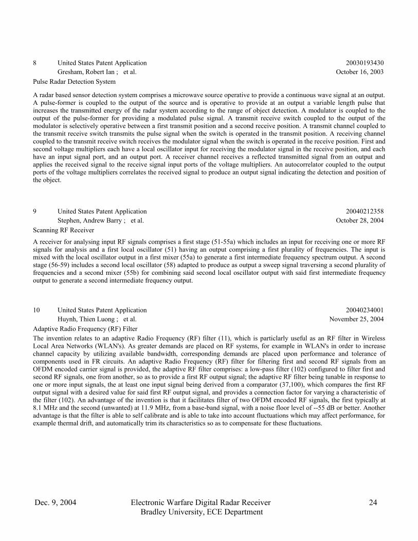
8 United States Patent Application 20030193430 Gresham, Robert Ian ; et al. October 16, 2003
Pulse Radar Detection System
A radar based sensor detection system comprises a microwave source operative to provide a continuous wave signal at an output.A pulse-former is coupled to the output of the source and is operative to provide at an output a variable length pulse thatincreases the transmitted energy of the radar system according to the range of object detection. A modulator is coupled to theoutput of the pulse-former for providing a modulated pulse signal. A transmit receive switch coupled to the output of themodulator is selectively operative between a first transmit position and a second receive position. A transmit channel coupled tothe transmit receive switch transmits the pulse signal when the switch is operated in the transmit position. A receiving channelcoupled to the transmit receive switch receives the modulator signal when the switch is operated in the receive position. First andsecond voltage multipliers each have a local oscillator input for receiving the modulator signal in the receive position, and eachhave an input signal port, and an output port. A receiver channel receives a reflected transmitted signal from an output andapplies the received signal to the receive signal input ports of the voltage multipliers. An autocorrelator coupled to the outputports of the voltage multipliers correlates the received signal to produce an output signal indicating the detection and position ofthe object.
9 United States Patent Application 20040212358 Stephen, Andrew Barry ; et al. October 28, 2004
Scanning RF Receiver
A receiver for analysing input RF signals comprises a first stage (51-55a) which includes an input for receiving one or more RFsignals for analysis and a first local oscillator (51) having an output comprising a first plurality of frequencies. The input ismixed with the local oscillator output in a first mixer (55a) to generate a first intermediate frequency spectrum output. A secondstage (56-59) includes a second local oscillator (58) adapted to produce as output a sweep signal traversing a second plurality offrequencies and a second mixer (55b) for combining said second local oscillator output with said first intermediate frequencyoutput to generate a second intermediate frequency output.
10 United States Patent Application 20040234001 Huynh, Thien Luong ; et al. November 25, 2004
Adaptive Radio Frequency (RF) FilterThe invention relates to an adaptive Radio Frequency (RF) filter (11), which is particlarly useful as an RF filter in WirelessLocal Area Networks (WLAN's). As greater demands are placed on RF systems, for example in WLAN's in order to increasechannel capacity by utilizing available bandwidth, corresponding demands are placed upon performance and tolerance ofcomponents used in FR circuits. An adaptive Radio Frequency (RF) filter for filtering first and second RF signals from anOFDM encoded carrier signal is provided, the adaptive RF filter comprises: a low-pass filter (102) configured to filter first andsecond RF signals, one from another, so as to provide a first RF output signal; the adaptive RF filter being tunable in response toone or more input signals, the at least one input signal being derived from a comparator (37,100), which compares the first RFoutput signal with a desired value for said first RF output signal, and provides a connection factor for varying a characteristic ofthe filter (102). An advantage of the invention is that it facilitates filter of two OFDM encoded RF signals, the first typically at8.1 MHz and the second (unwanted) at 11.9 MHz, from a base-band signal, with a noise floor level of --55 dB or better. Anotheradvantage is that the filter is able to self calibrate and is able to take into account fluctuations which may affect performance, forexample thermal drift, and automatically trim its characteristics so as to compensate for these fluctuations.
Dec. 9, 2004 Electronic Warfare Digital Radar ReceiverBradley University, ECE Department
24
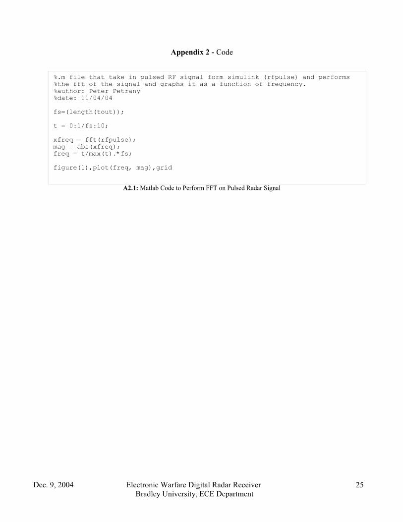
Appendix 2 - Code
A2.1: Matlab Code to Perform FFT on Pulsed Radar Signal
Dec. 9, 2004 Electronic Warfare Digital Radar ReceiverBradley University, ECE Department
25
%.m file that take in pulsed RF signal form simulink (rfpulse) and performs%the fft of the signal and graphs it as a function of frequency.%author: Peter Petrany%date: 11/04/04 fs=(length(tout));t = 0:1/fs:10; xfreq = fft(rfpulse);mag = abs(xfreq);freq = t/max(t).*fs; figure(1),plot(freq, mag),grid

A2.2: Matlab Code to Determine RF Signal Characteristics from FFT of A2.1
Dec. 9, 2004 Electronic Warfare Digital Radar ReceiverBradley University, ECE Department
26
%Senior Project 11/06/04%author Peter Petrany (and Mike Gahl)%runs fftout2.m file then proceeds to find the pulse width (PW) RF%frequency(fRF) and the pulse repetition rate (PRR)fftout2 %generates FFT output after rfspecs3 simulink file %is ran (data is put into workspace under %variable 'x'maxmag=max(mag); %find global maxk=1;while mag(k)~=maxmag %scan for array entry of max value, this k=k+1; %this allows us to find the freq at which the end %max peak occursn=k; %n=k value where mag is maxfrf=freq(n); %RF freqlocalpeak=mag(n);while mag(k+1) < mag(k) %searches for next sampling peak k=k+1;endwhile mag(k+1)>mag(k) k=k+1;endT=(abs(freq(n)-freq(k)))^(-1); %Period measurementPRR=(abs(freq(n)-freq(k))); %Pulse repetition ratelocalpeak2=mag(k); %ko k-n = offset of peaksoffset=k-n;newk=k+offset;while mag(newk+offset)<mag(newk) %searches for first trough newk=newk+offset;endPW=abs(freq(newk)-freq(n))^(-1); %tau value disp('RF Frequency(fRF): ');frfdisp('Pulse Width(PW): ');PWdisp('Pulse Repetition Rate(PRR): ');PRRdisp('Pulse Period(T): ');T