seminar agenda - nmea · seminar agenda 1. nmea 2000® products 2. ... speed water reference 128267...
TRANSCRIPT
Seminar Agenda
1. NMEA 2000® Products2. Response to Customer Feedback3. Airmar Transducer Models4. Installation-Specific Products5. Converting Transducers6. Installation & Troubleshooting7. In-Hull Transducers8. Broadband Transducers9. Transom-Mount Installation & Troubleshooting
NMEA 2000® Sensors
NMEA 0183 & 2000® Smart Sensors
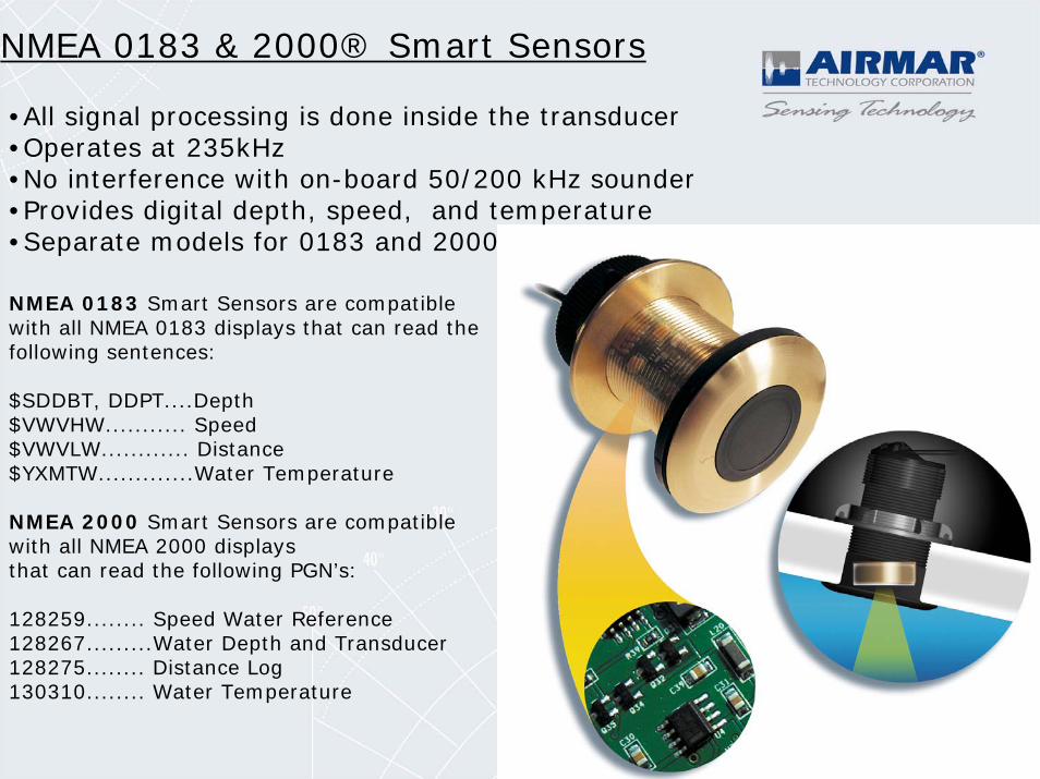
•All signal processing is done inside the transducer•Operates at 235kHz•No interference with on-board 50/200 kHz sounder•Provides digital depth, speed, and temperature•Separate models for 0183 and 2000
NMEA 0183 Smart Sensors are compatible with all NMEA 0183 displays that can read the following sentences:
$SDDBT, DDPT....Depth $VWVHW........... Speed $VWVLW............ Distance$YXMTW.............Water Temperature
NMEA 2000 Smart Sensors are compatible with all NMEA 2000 displays that can read the following PGN’s:
128259........ Speed Water Reference 128267.........Water Depth and Transducer128275........ Distance Log 130310........ Water Temperature
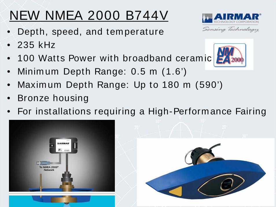
NEW NMEA 2000 B744V• Depth, speed, and temperature• 235 kHz• 100 Watts Power with broadband ceramic• Minimum Depth Range: 0.5 m (1.6’)• Maximum Depth Range: Up to 180 m (590’)• Bronze housing• For installations requiring a High-Performance Fairing
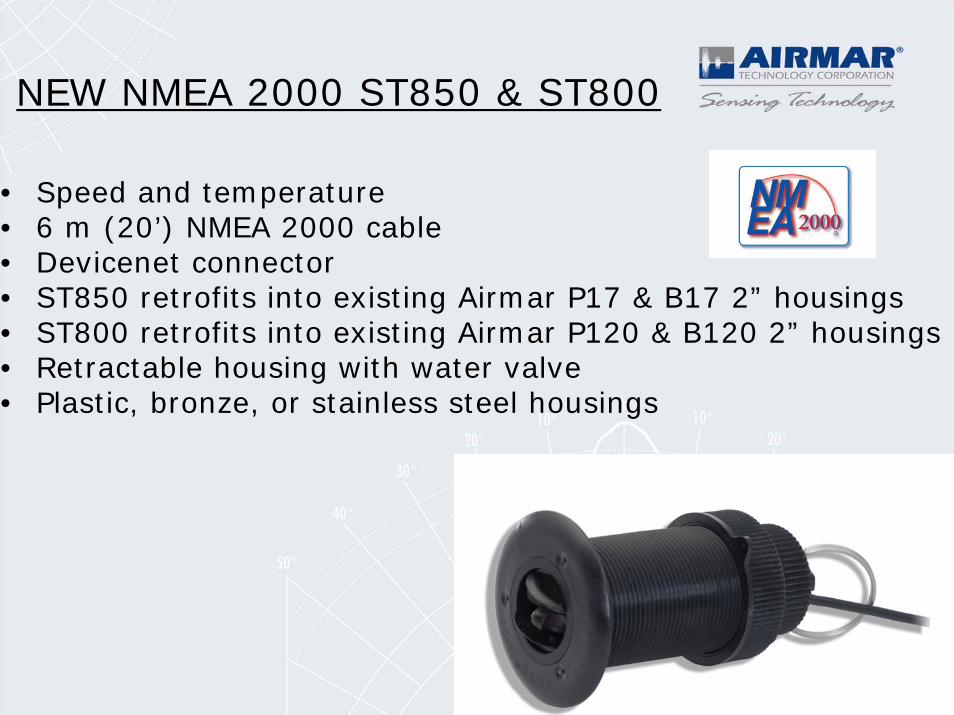
NEW NMEA 2000 ST850 & ST800
• Speed and temperature• 6 m (20’) NMEA 2000 cable• Devicenet connector• ST850 retrofits into existing Airmar P17 & B17 2” housings• ST800 retrofits into existing Airmar P120 & B120 2” housings• Retractable housing with water valve• Plastic, bronze, or stainless steel housings
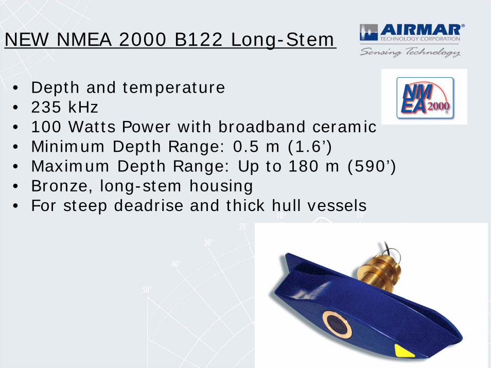
NEW NMEA 2000 B122 Long-Stem
• Depth and temperature• 235 kHz• 100 Watts Power with broadband ceramic• Minimum Depth Range: 0.5 m (1.6’)• Maximum Depth Range: Up to 180 m (590’)• Bronze, long-stem housing• For steep deadrise and thick hull vessels
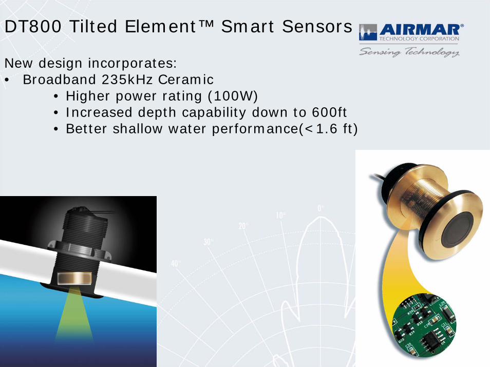
DT800 Tilted Element™ Smart Sensors
New design incorporates:• Broadband 235kHz Ceramic
• Higher power rating (100W)• Increased depth capability down to 600ft• Better shallow water performance(<1.6 ft)
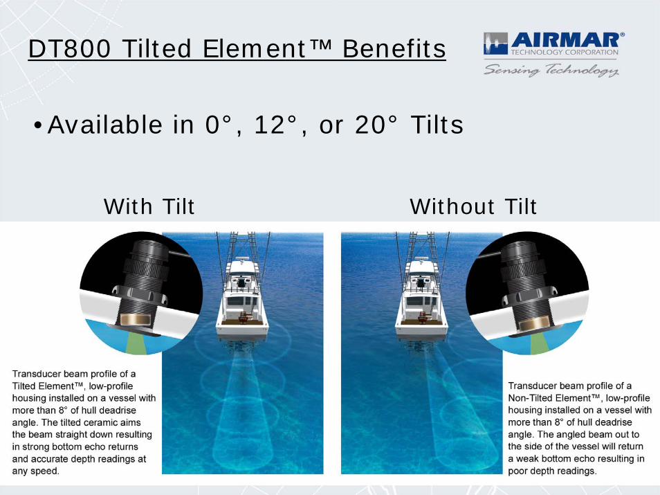
DT800 Tilted Element™ Benefits
With Tilt Without Tilt
•Available in 0°, 12°, or 20° Tilts
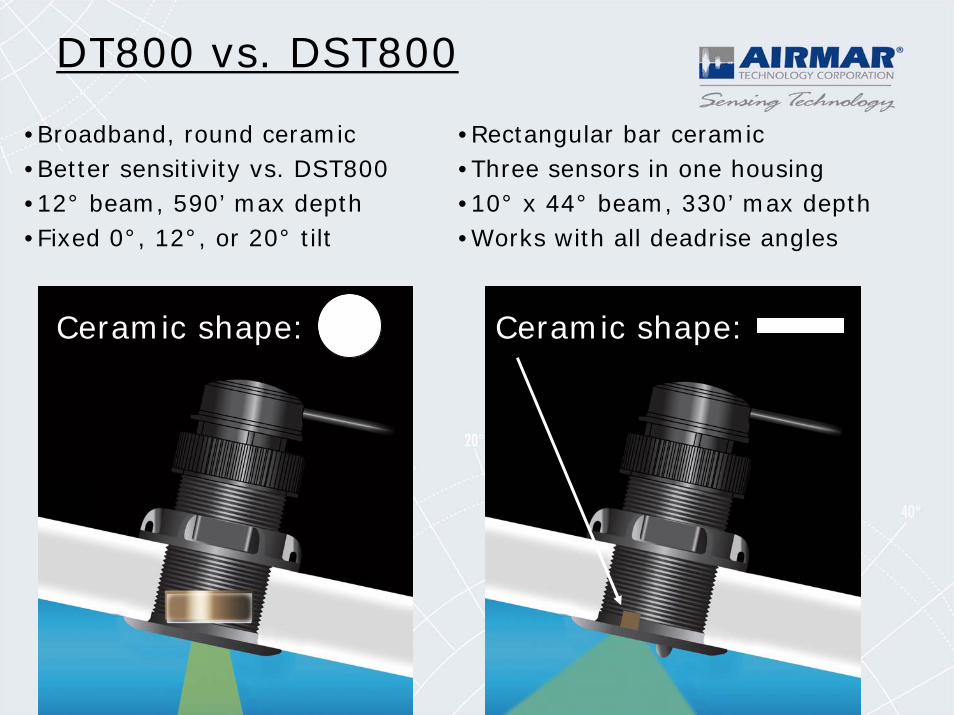
DT800 vs. DST800
•Broadband, round ceramic •Better sensitivity vs. DST800•12° beam, 590’ max depth•Fixed 0°, 12°, or 20° tilt
•Rectangular bar ceramic•Three sensors in one housing•10° x 44° beam, 330’ max depth•Works with all deadrise angles
Ceramic shape: Ceramic shape:
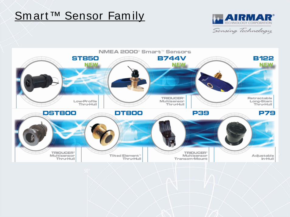
Smart™ Sensor Family
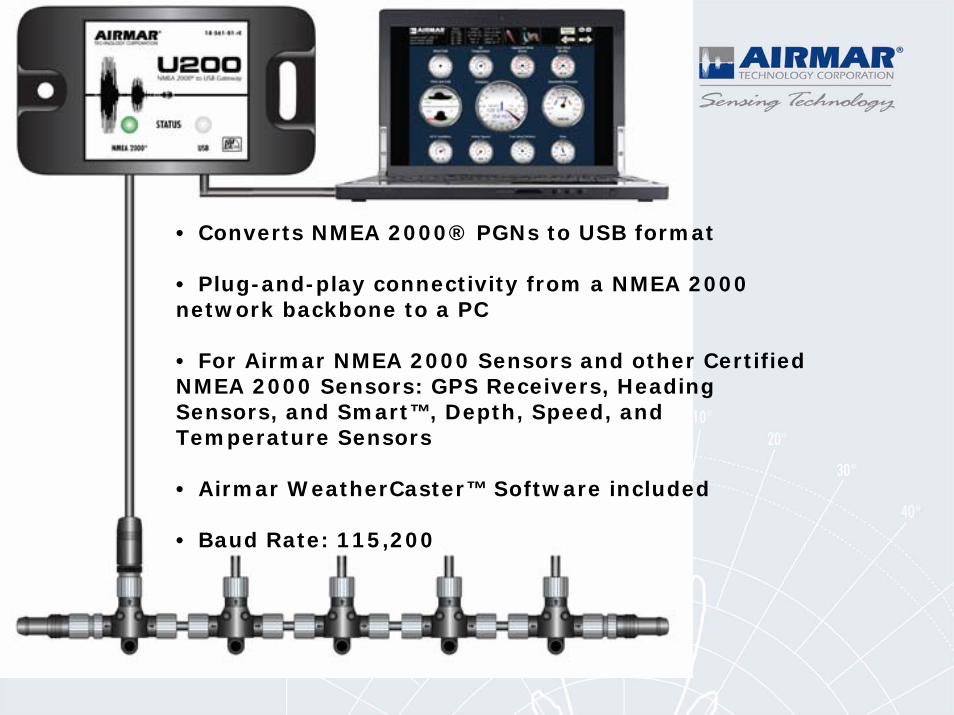
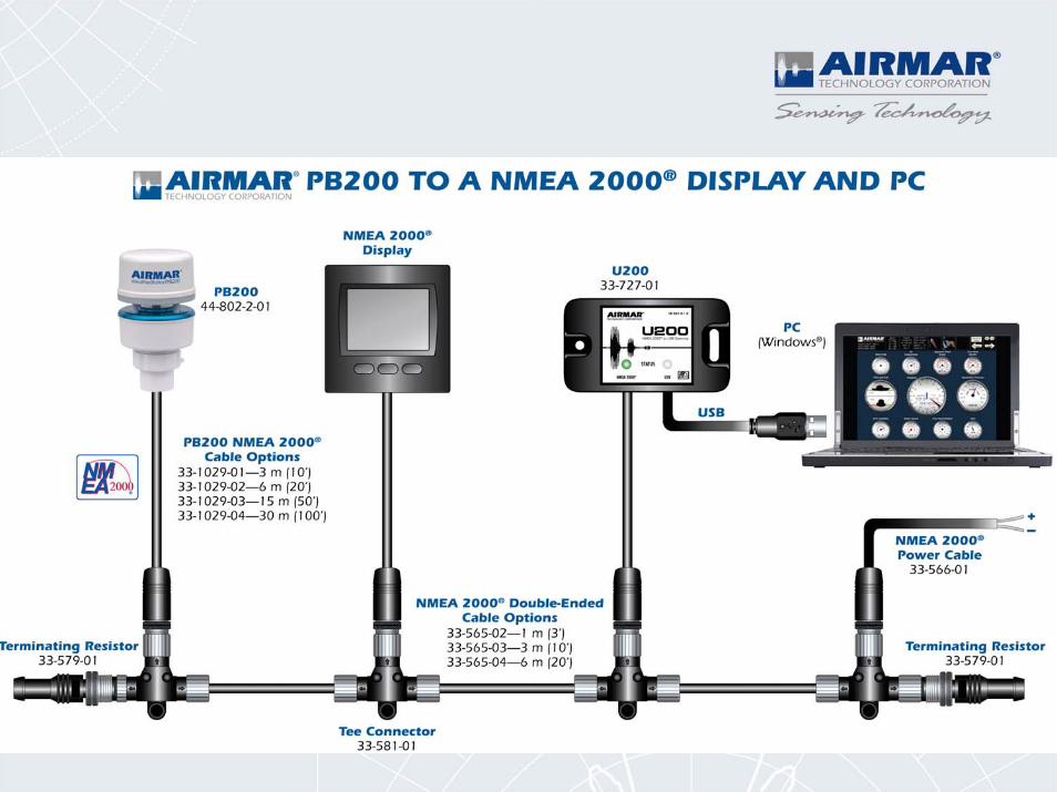
• Converts NMEA 2000® PGNs to USB format
• Plug-and-play connectivity from a NMEA 2000network backbone to a PC
• For Airmar NMEA 2000 Sensors and other CertifiedNMEA 2000 Sensors: GPS Receivers, HeadingSensors, and Smart™, Depth, Speed, andTemperature Sensors
• Airmar WeatherCaster™ Software included
• Baud Rate: 115,200
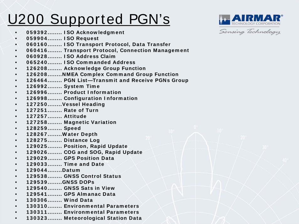
U200 Supported PGN’s• 059392........ ISO Acknowledgment• 059904........ ISO Request• 060160........ ISO Transport Protocol, Data Transfer• 060416........ Transport Protocol, Connection Management• 060928........ ISO Address Claim• 065240........ ISO Commanded Address• 126208........ Acknowledge Group Function• 126208........NMEA Complex Command Group Function• 126464........ PGN List—Transmit and Receive PGNs Group• 126992........ System Time• 126996........ Product Information• 126998........ Configuration Information• 127250........Vessel Heading• 127251........ Rate of Turn• 127257........ Attitude• 127258........ Magnetic Variation• 128259........ Speed• 128267........Water Depth• 128275........ Distance Log• 129025........ Position, Rapid Update• 129026........ COG and SOG, Rapid Update• 129029........ GPS Position Data• 129033........ Time and Date• 129044........Datum• 129538........ GNSS Control Status• 129539........GNSS DOPs• 129540........ GNSS Sats in View• 129541........ GPS Almanac Data• 130306........ Wind Data• 130310........ Environmental Parameters• 130311........ Environmental Parameters• 130323........ Meteorological Station Data
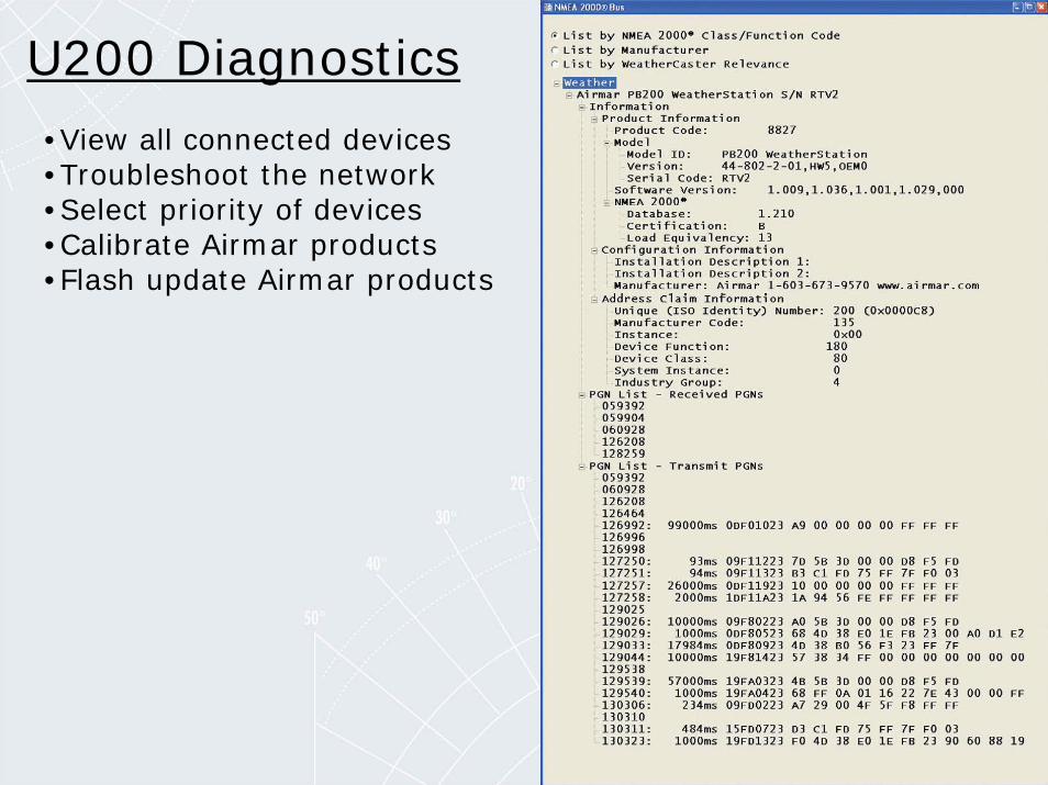
U200 Diagnostics•View all connected devices•Troubleshoot the network•Select priority of devices•Calibrate Airmar products•Flash update Airmar products
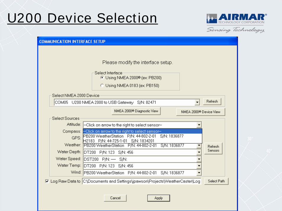
U200 Device Selection
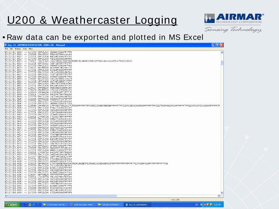
U200 & Weathercaster Logging•Raw data can be exported and plotted in MS Excel
PB200 WeatherStation® Instrument
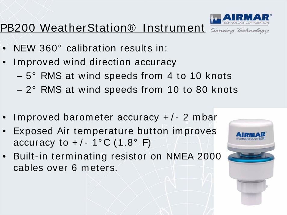
• NEW 360° calibration results in:• Improved wind direction accuracy
– 5° RMS at wind speeds from 4 to 10 knots– 2° RMS at wind speeds from 10 to 80 knots
• Improved barometer accuracy +/- 2 mbar• Exposed Air temperature button improves
accuracy to +/- 1°C (1.8° F)• Built-in terminating resistor on NMEA 2000
cables over 6 meters.
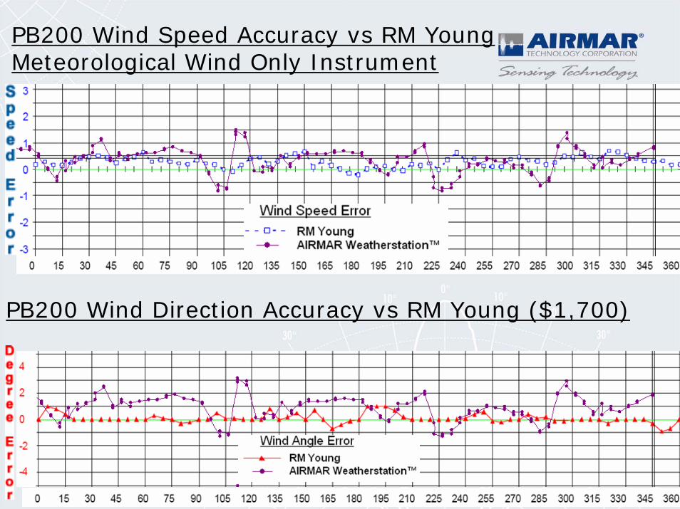
PB200 Wind Speed Accuracy vs RM Young Meteorological Wind Only Instrument
PB200 Wind Direction Accuracy vs RM Young ($1,700)
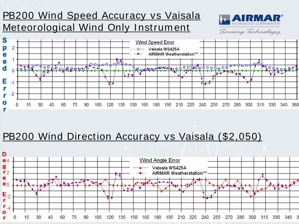
PB200 Wind Speed Accuracy vs Vaisala Meteorological Wind Only Instrument
PB200 Wind Direction Accuracy vs Vaisala ($2,050)
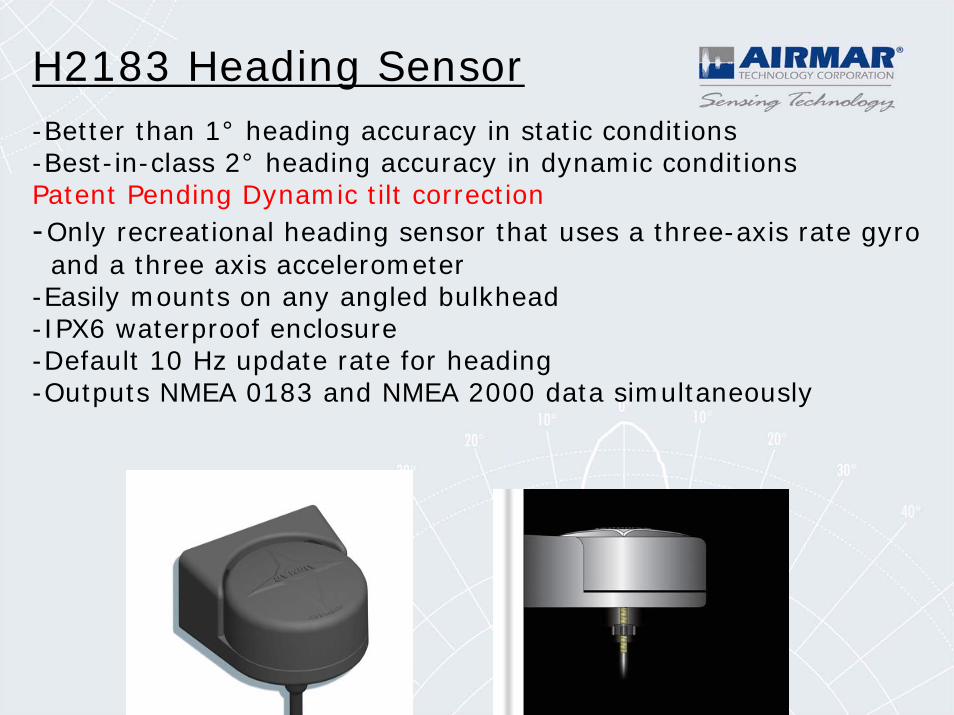
-Better than 1° heading accuracy in static conditions -Best-in-class 2° heading accuracy in dynamic conditions Patent Pending Dynamic tilt correction-Only recreational heading sensor that uses a three-axis rate gyroand a three axis accelerometer
-Easily mounts on any angled bulkhead -IPX6 waterproof enclosure-Default 10 Hz update rate for heading-Outputs NMEA 0183 and NMEA 2000 data simultaneously
H2183 Heading Sensor
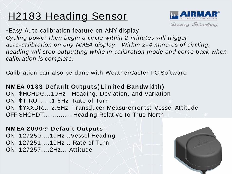
-Easy Auto calibration feature on ANY displayCycling power then begin a circle within 2 minutes will trigger auto-calibration on any NMEA display. Within 2-4 minutes of circling,heading will stop outputting while in calibration mode and come back when calibration is complete.
Calibration can also be done with WeatherCaster PC Software
NMEA 0183 Default Outputs(Limited Bandwidth)ON $HCHDG...10Hz Heading, Deviation, and VariationON $TIROT.....1.6Hz Rate of TurnON $YXXDR....2.5Hz Transducer Measurements: Vessel AttitudeOFF $HCHDT............. Heading Relative to True North
NMEA 2000® Default OutputsON 127250....10Hz ..Vessel HeadingON 127251....10Hz .. Rate of TurnON 127257....2Hz... Attitude
H2183 Heading Sensor
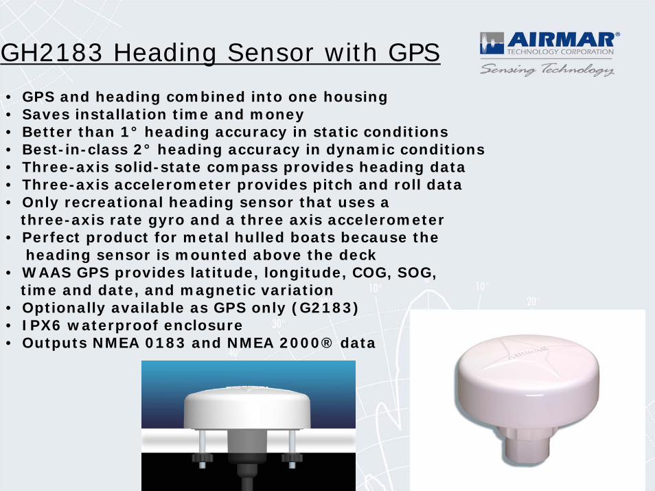
• GPS and heading combined into one housing • Saves installation time and money • Better than 1° heading accuracy in static conditions • Best-in-class 2° heading accuracy in dynamic conditions • Three-axis solid-state compass provides heading data • Three-axis accelerometer provides pitch and roll data • Only recreational heading sensor that uses a
three-axis rate gyro and a three axis accelerometer• Perfect product for metal hulled boats because the
heading sensor is mounted above the deck• WAAS GPS provides latitude, longitude, COG, SOG,
time and date, and magnetic variation • Optionally available as GPS only (G2183) • IPX6 waterproof enclosure• Outputs NMEA 0183 and NMEA 2000® data
GH2183 Heading Sensor with GPS
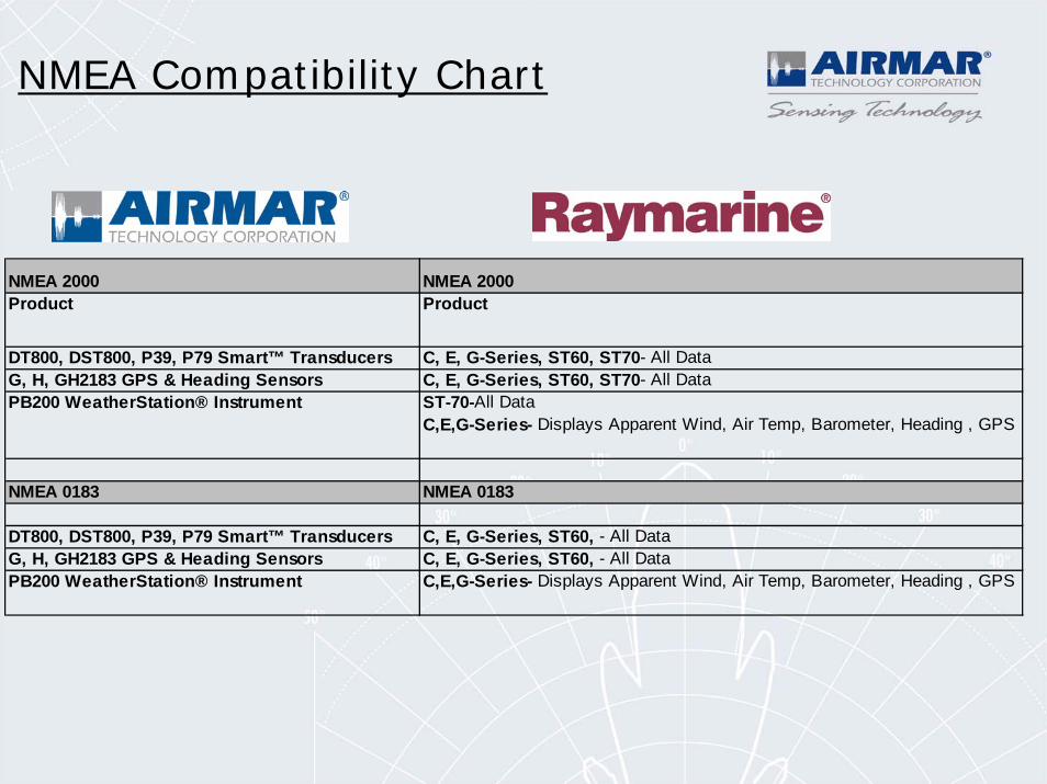
NMEA 2000 NMEA 2000Product Product
DT800, DST800, P39, P79 Smart™ Transducers C, E, G-Series, ST60, ST70- All DataG, H, GH2183 GPS & Heading Sensors C, E, G-Series, ST60, ST70- All DataPB200 WeatherStation® Instrument ST-70-All Data
C,E,G-Series- Displays Apparent Wind, Air Temp, Barometer, Heading , GPS
NMEA 0183 NMEA 0183
DT800, DST800, P39, P79 Smart™ Transducers C, E, G-Series, ST60, - All DataG, H, GH2183 GPS & Heading Sensors C, E, G-Series, ST60, - All DataPB200 WeatherStation® Instrument C,E,G-Series- Displays Apparent Wind, Air Temp, Barometer, Heading , GPS
NMEA Compatibility Chart
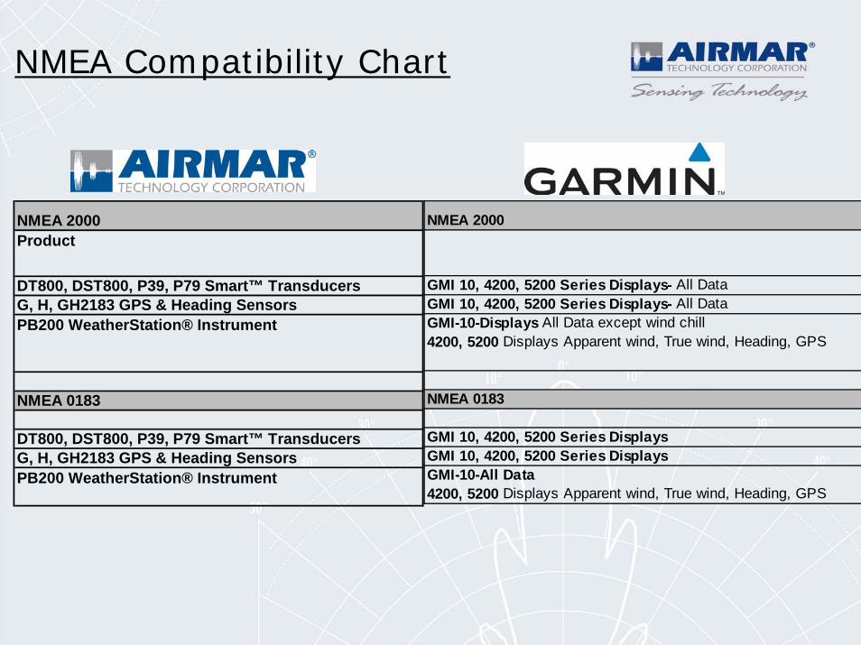
NMEA 2000
GMI 10, 4200, 5200 Series Displays- All DataGMI 10, 4200, 5200 Series Displays- All DataGMI-10-Displays All Data except wind chill 4200, 5200 Displays Apparent wind, True wind, Heading, GPS
NMEA 0183
GMI 10, 4200, 5200 Series DisplaysGMI 10, 4200, 5200 Series DisplaysGMI-10-All Data 4200, 5200 Displays Apparent wind, True wind, Heading, GPS
NMEA 2000Product
DT800, DST800, P39, P79 Smart™ TransducersG, H, GH2183 GPS & Heading SensorsPB200 WeatherStation® Instrument
NMEA 0183
DT800, DST800, P39, P79 Smart™ TransducersG, H, GH2183 GPS & Heading SensorsPB200 WeatherStation® Instrument
NMEA Compatibility Chart
NMEA 2000Product
DT800, DST800, P39, P79 Smart™ TransducersG, H, GH2183 GPS & Heading SensorsPB200 WeatherStation® Instrument
NMEA 0183
DT800, DST800, P39, P79 Smart™ TransducersG, H, GH2183 GPS & Heading SensorsPB200 WeatherStation® Instrument
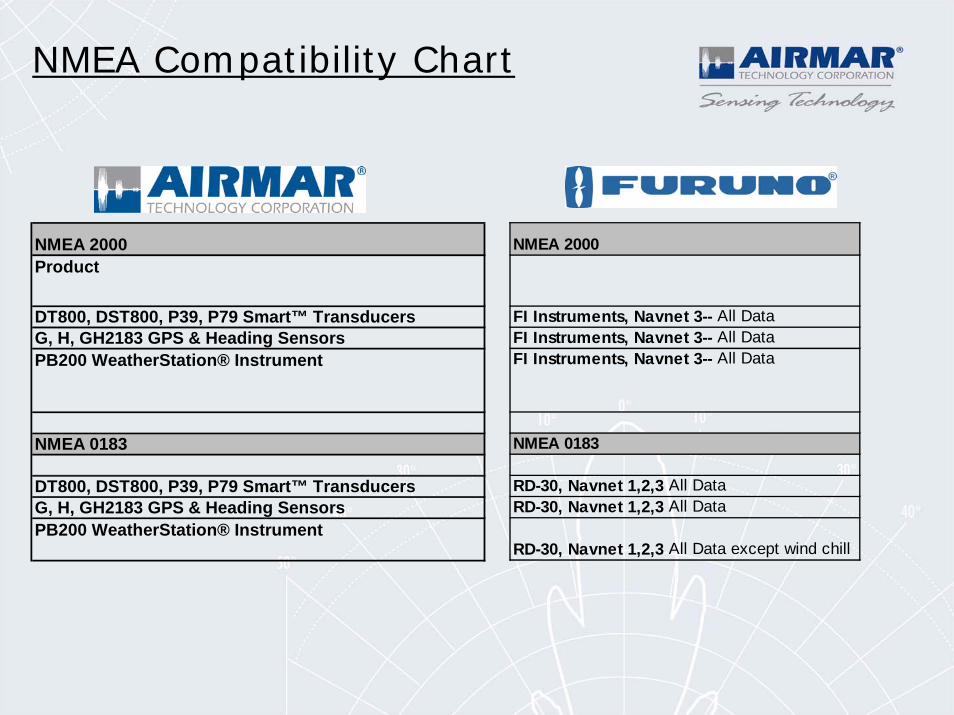
NMEA 2000
FI Instruments, Navnet 3-- All DataFI Instruments, Navnet 3-- All DataFI Instruments, Navnet 3-- All Data
NMEA 0183
RD-30, Navnet 1,2,3 All Data RD-30, Navnet 1,2,3 All Data
RD-30, Navnet 1,2,3 All Data except wind chill
NMEA Compatibility Chart
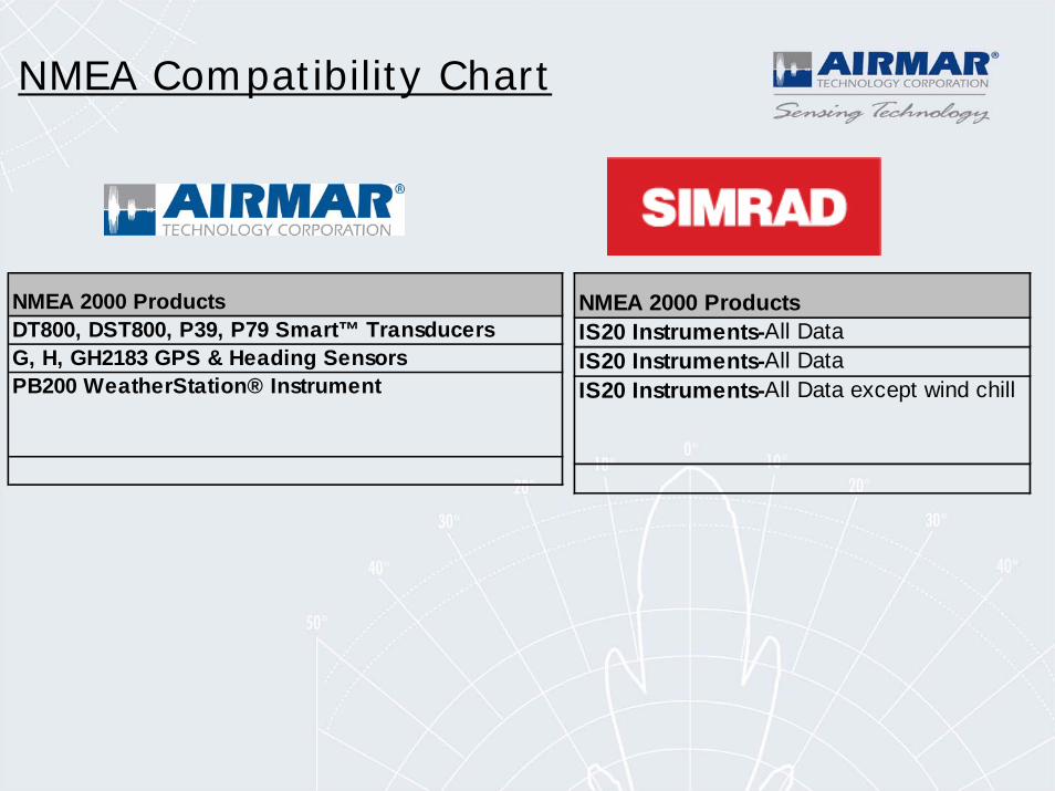
NMEA Compatibility Chart
NMEA 2000 ProductsIS20 Instruments-All DataIS20 Instruments-All DataIS20 Instruments-All Data except wind chill
NMEA 2000 ProductsDT800, DST800, P39, P79 Smart™ TransducersG, H, GH2183 GPS & Heading SensorsPB200 WeatherStation® Instrument
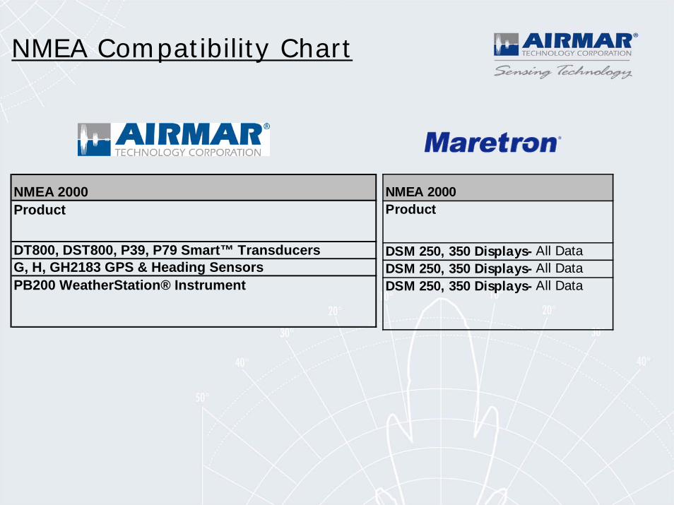
NMEA Compatibility Chart
NMEA 2000Product
DSM 250, 350 Displays- All DataDSM 250, 350 Displays- All DataDSM 250, 350 Displays- All Data
NMEA 2000Product
DT800, DST800, P39, P79 Smart™ TransducersG, H, GH2183 GPS & Heading SensorsPB200 WeatherStation® Instrument
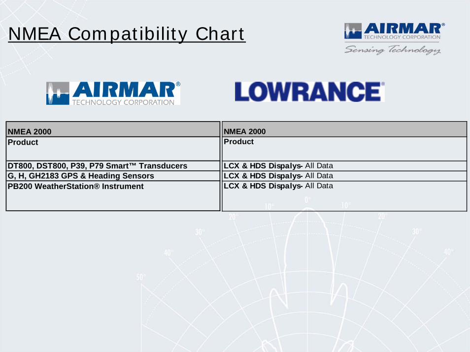
NMEA Compatibility Chart
NMEA 2000Product
LCX & HDS Dispalys- All DataLCX & HDS Dispalys- All DataLCX & HDS Dispalys- All Data
NMEA 2000Product
DT800, DST800, P39, P79 Smart™ TransducersG, H, GH2183 GPS & Heading SensorsPB200 WeatherStation® Instrument
Response to Customer Feedback
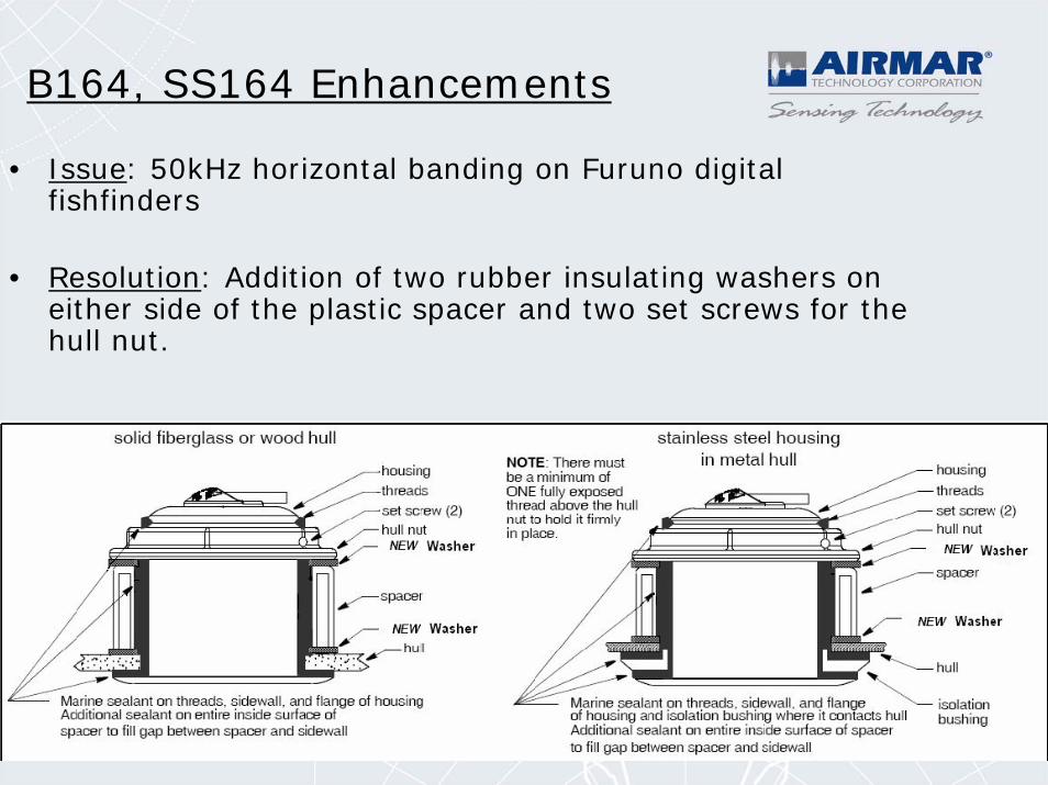
B164, SS164 Enhancements
• Issue: 50kHz horizontal banding on Furuno digital fishfinders
• Resolution: Addition of two rubber insulating washers on either side of the plastic spacer and two set screws for the hull nut.
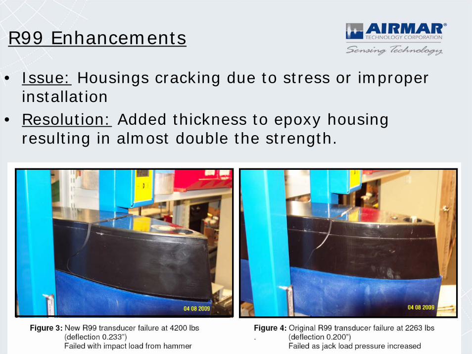
R99 Enhancements
• Issue: Housings cracking due to stress or improper installation
• Resolution: Added thickness to epoxy housing resulting in almost double the strength.
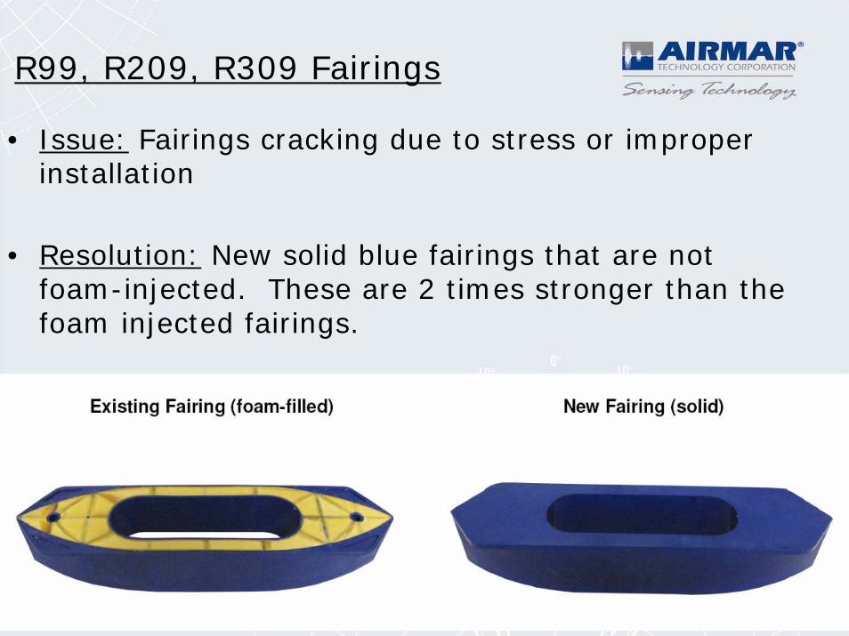
R99, R209, R309 Fairings
• Issue: Fairings cracking due to stress or improper installation
• Resolution: New solid blue fairings that are not foam-injected. These are 2 times stronger than the foam injected fairings.
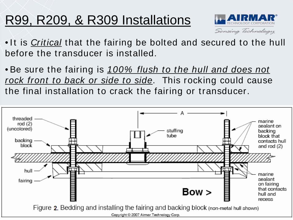
R99, R209, & R309 Installations•It is Critical that the fairing be bolted and secured to the hull before the transducer is installed.
•Be sure the fairing is 100% flush to the hull and does not rock front to back or side to side. This rocking could cause the final installation to crack the fairing or transducer.
R99, R209, & R309 Installations
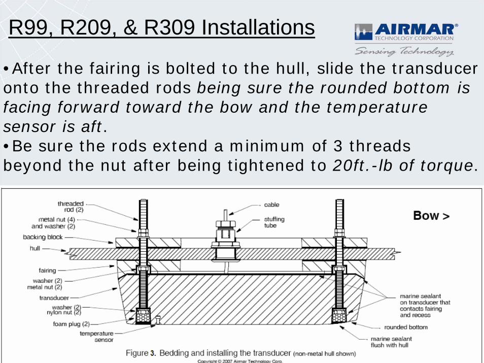
•After the fairing is bolted to the hull, slide the transducer onto the threaded rods being sure the rounded bottom is facing forward toward the bow and the temperature sensor is aft.•Be sure the rods extend a minimum of 3 threads beyond the nut after being tightened to 20ft.-lb of torque.
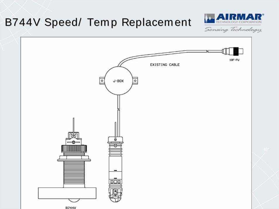
B744V Speed/ Temp ReplacementB744V Speed/ Temp Replacement
B744V Speed/ Temp ReplacementB744V Speed/ Temp Replacement
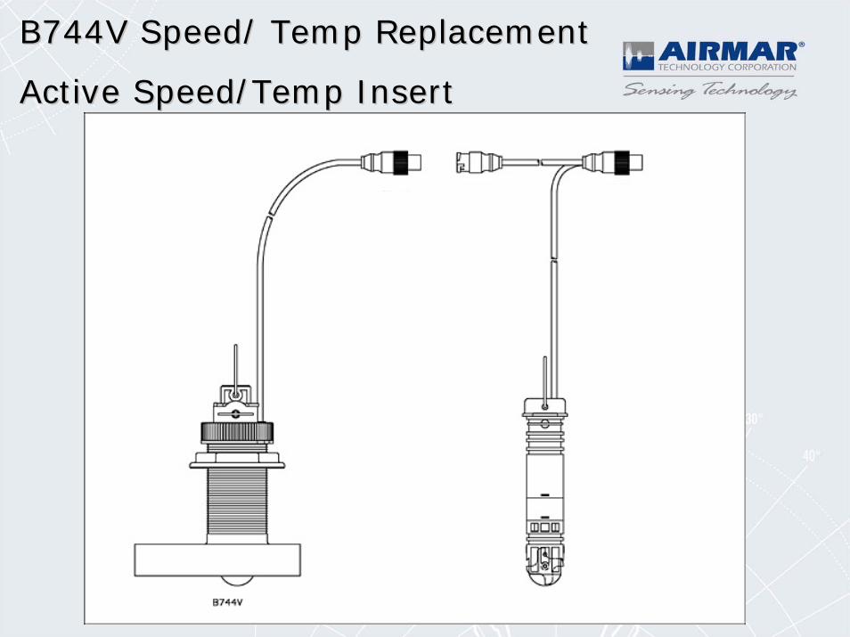
Active Speed/Temp InsertActive Speed/Temp Insert
Smart Sensor Enhancements:DT800, DST800, P39, P79
• Airmar has developed new firmware for Smart Sensors that improves depth tracking ability at all depths from shallow to deep.
• This firmware addresses the following customer reported issues:
• DT800 depth readings in shallow, sandy bottom (<3ft) occasionally locking in on second or third echoes. The sensor could occasionally report depths 2x,3x, or 4x greater than the actual depth.
• DST800 sensors mounted on steep dead rise angles occasionally locking in on the boats own bow wake or surface waves. The sensor would then report a very shallow depth <3 ft. This was reported more when the vessel is in very deep water beyond the sensors maximum depth capability.
How Smart Sensors track the bottomFirmware Version: 1.011
• Before an Airmar Smart Sensor reports a depth as valid, it must have confidence that the integrity of the target being tracked is truly the bottom and not a fish, bubbles, or debris in the water.
• The confidence increases each time a potential target is seen at the same approximate depth. This helps eliminate a smart sensor reporting on targets that are not persistent over time (fish, debris, etc).
• Once the confidence in a potential target increases to a predetermined level, the sensor starts tracking the target, and reports its depth as valid. It will take at least 3 seconds for a target to enter depth tracking mode.
How Smart Sensors track the bottomFirmware Version: 1.011
•If the sensor loses track of a target at the same depth, the confidence in its depth decreases, but it will keep repeating the last good depth.
•Once the confidence decreases to a predetermined level, the sensor abandons the lock on the bottom and declares the depth as data not available, and starts looking for new potential targets that it can report on with confidence.
•The time for a high confidence locked target to be abandoned depends on the depth, it is between 4 seconds in shallow water and 8 seconds in deep water (>250ft).
How Smart Sensors track the bottomFirmware Version: 1.011
• Shallow water operation: The sensor can track bottom into as little as 1.5' of water before it loses its lock, but it will not be able to regain a lock until about 3' of water is seen.
• Deep-water operation: When the sensor gets beyond its depth capability, our new firmware minimizes the possibility of locking on surface waves or clutter. Depth is reported as data not available vs. reporting random shallow readings even though the vessel is in very deep water.
• Airmar Smart Sensors can provide a proprietary Depth Quality Factor PGN that reports a value from 1-10 based on depth confidence level.
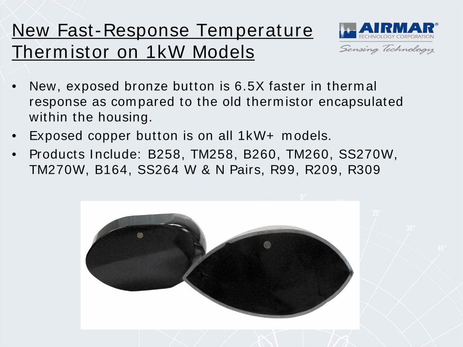
New Fast-Response Temperature Thermistor on 1kW Models
• New, exposed bronze button is 6.5X faster in thermal response as compared to the old thermistor encapsulated within the housing.
• Exposed copper button is on all 1kW+ models.• Products Include: B258, TM258, B260, TM260, SS270W,
TM270W, B164, SS264 W & N Pairs, R99, R209, R309
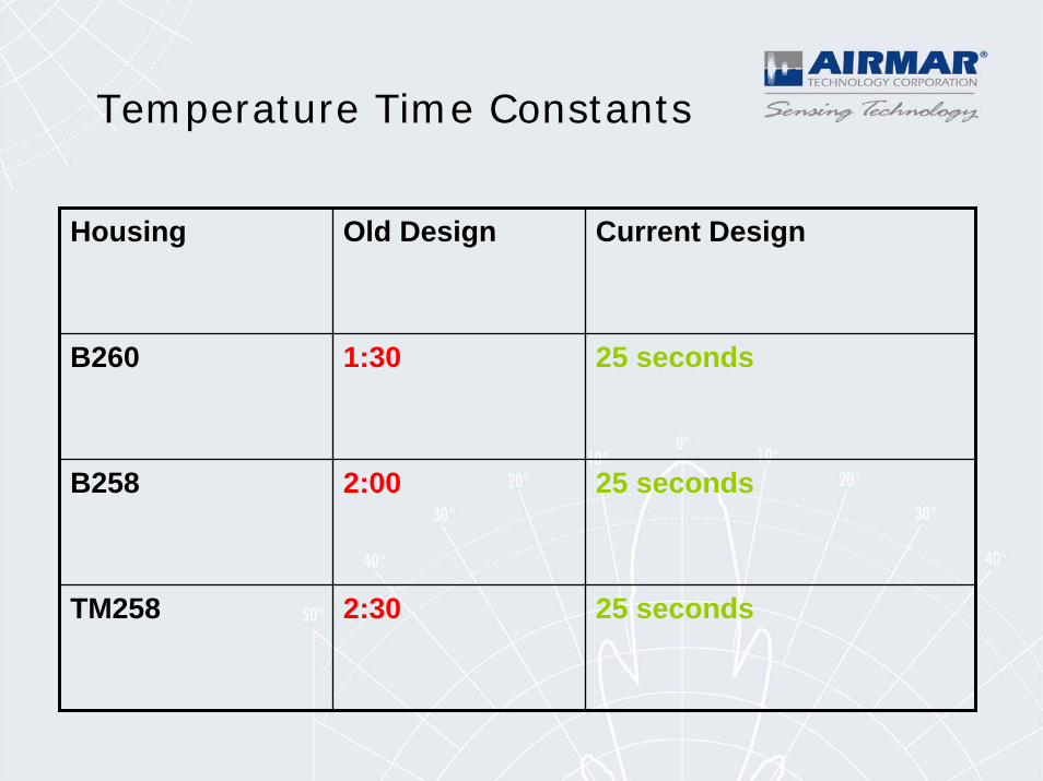
Housing Old Design Current Design
B260 1:30 25 seconds
B258 2:00 25 seconds
TM258 2:30 25 seconds
Temperature Time Constants
Airmar Transducer Models
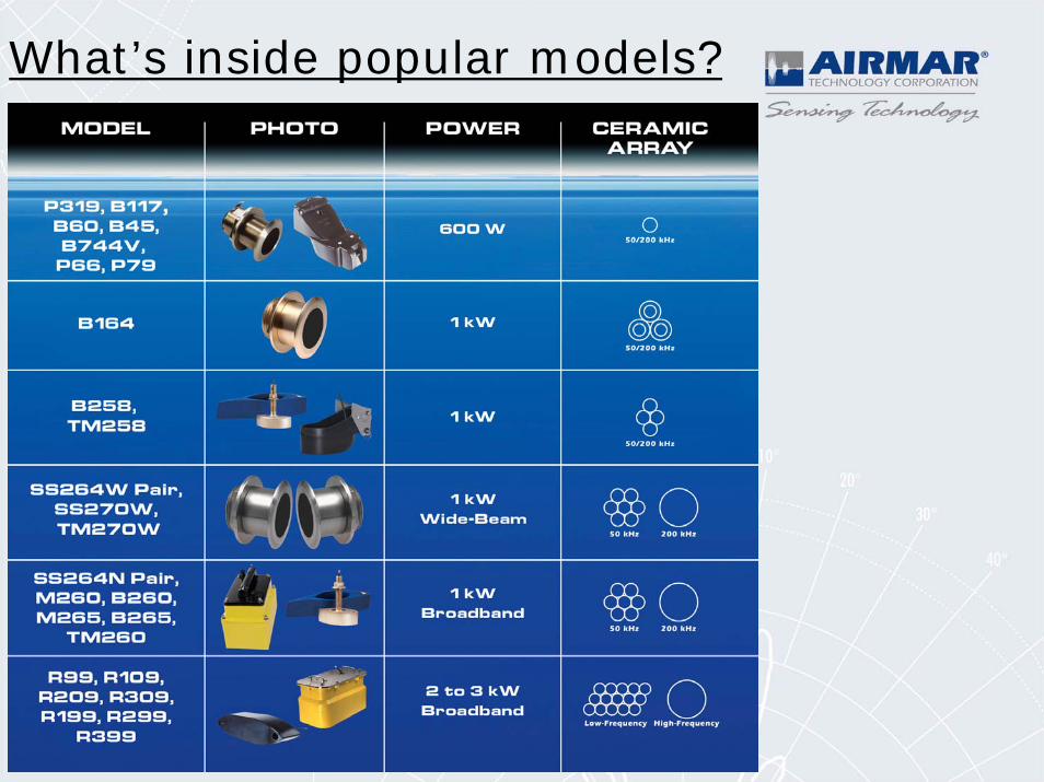
What’s inside popular models?
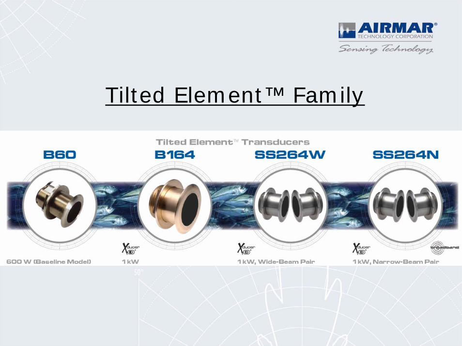
Tilted Element™ Family
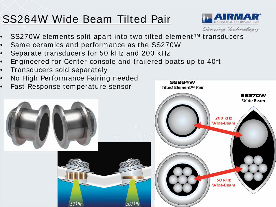
SS264W Wide Beam Tilted Pair • SS270W elements split apart into two tilted element™ transducers• Same ceramics and performance as the SS270W• Separate transducers for 50 kHz and 200 kHz• Engineered for Center console and trailered boats up to 40ft• Transducers sold separately• No High Performance Fairing needed• Fast Response temperature sensor
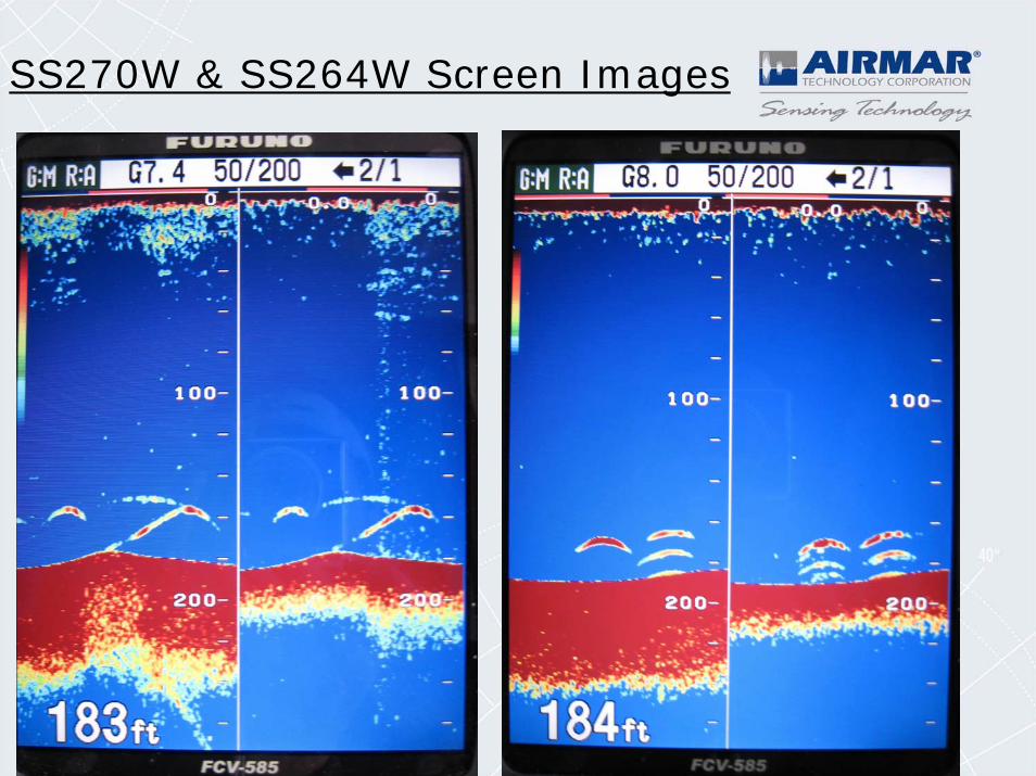
SS270W & SS264W Screen Images
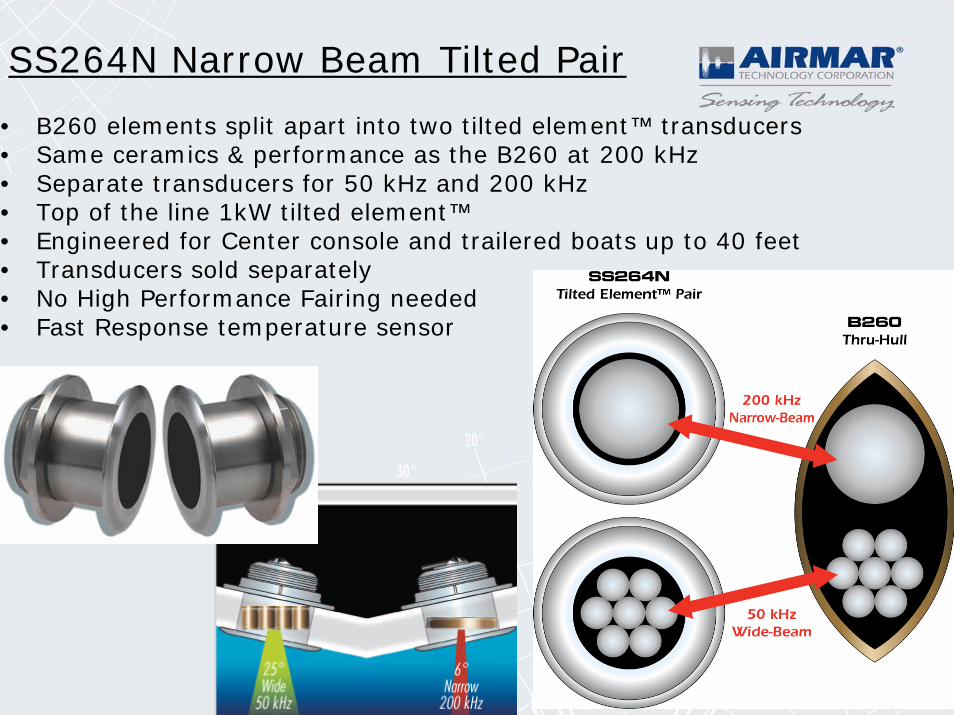
• B260 elements split apart into two tilted element™ transducers• Same ceramics & performance as the B260 at 200 kHz• Separate transducers for 50 kHz and 200 kHz• Top of the line 1kW tilted element™• Engineered for Center console and trailered boats up to 40 feet• Transducers sold separately• No High Performance Fairing needed• Fast Response temperature sensor
SS264N Narrow Beam Tilted Pair
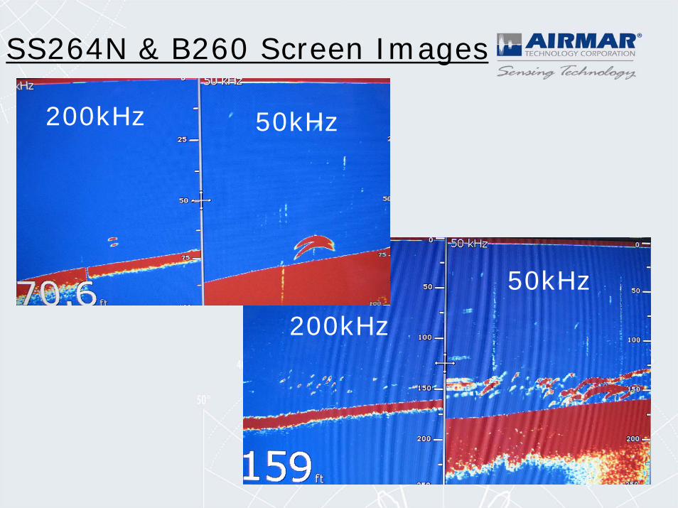
SS264N & B260 Screen Images
200kHz
50kHz
50kHz200kHz
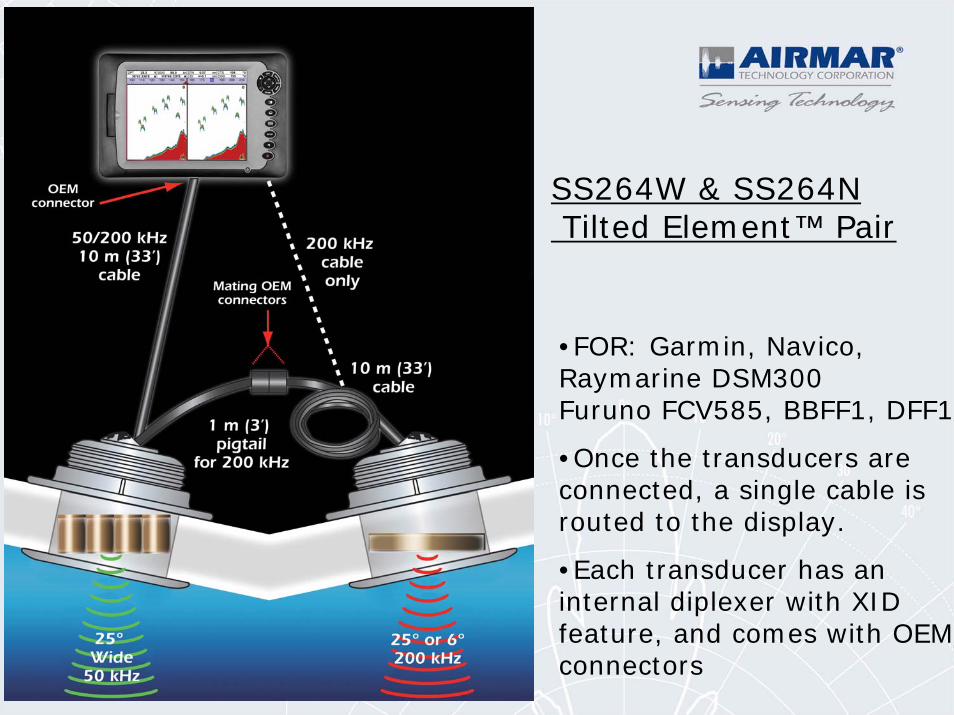
SS264W & SS264NTilted Element™ Pair
•FOR: Garmin, Navico, Raymarine DSM300 Furuno FCV585, BBFF1, DFF1
•Once the transducers are connected, a single cable is routed to the display.
•Each transducer has an internal diplexer with XID feature, and comes with OEM connectors
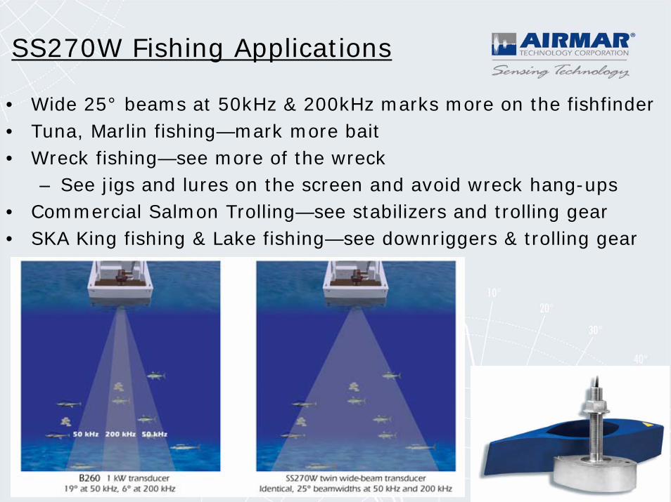
SS270W Fishing Applications
• Wide 25° beams at 50kHz & 200kHz marks more on the fishfinder• Tuna, Marlin fishing—mark more bait• Wreck fishing—see more of the wreck
– See jigs and lures on the screen and avoid wreck hang-ups• Commercial Salmon Trolling—see stabilizers and trolling gear• SKA King fishing & Lake fishing—see downriggers & trolling gear
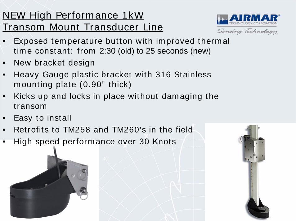
NEW High Performance 1kW Transom Mount Transducer Line• Exposed temperature button with improved thermal
time constant: from 2:30 (old) to 25 seconds (new)• New bracket design• Heavy Gauge plastic bracket with 316 Stainless
mounting plate (0.90” thick)• Kicks up and locks in place without damaging the
transom• Easy to install• Retrofits to TM258 and TM260’s in the field• High speed performance over 30 Knots
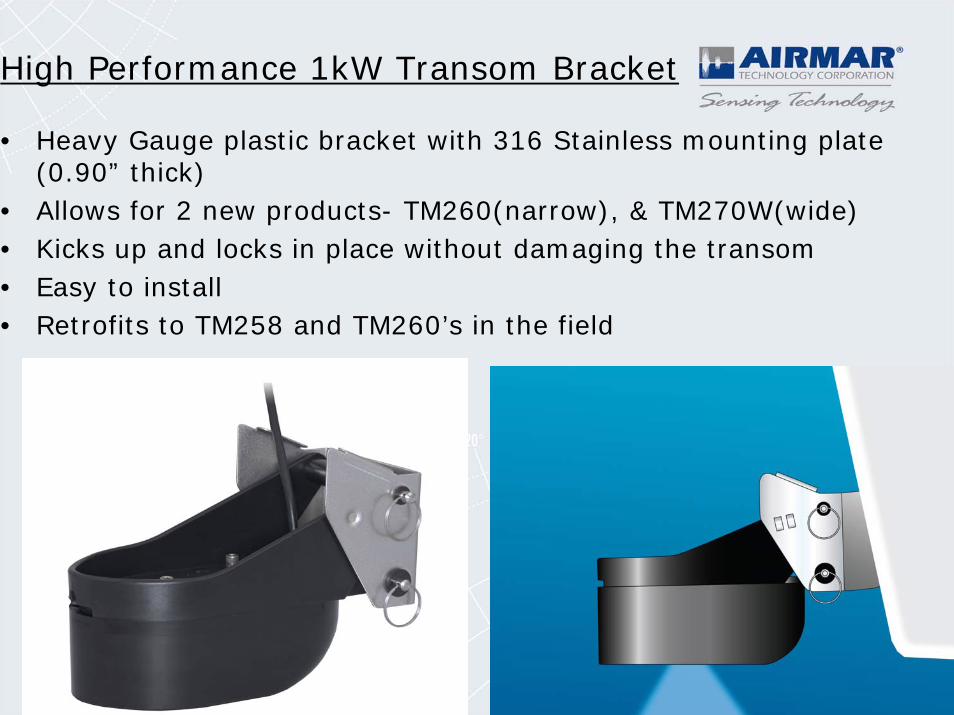
High Performance 1kW Transom Bracket
• Heavy Gauge plastic bracket with 316 Stainless mounting plate (0.90” thick)
• Allows for 2 new products- TM260(narrow), & TM270W(wide)• Kicks up and locks in place without damaging the transom• Easy to install• Retrofits to TM258 and TM260’s in the field
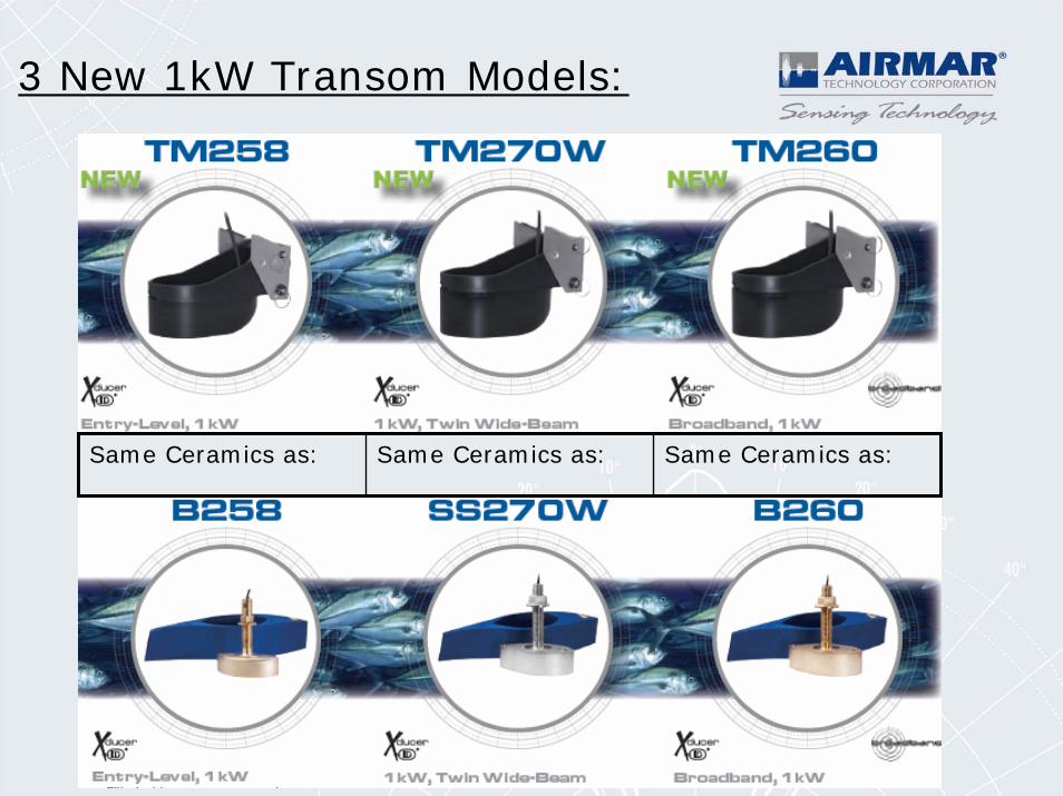
3 New 1kW Transom Models:
Same Ceramics as: Same Ceramics as: Same Ceramics as:
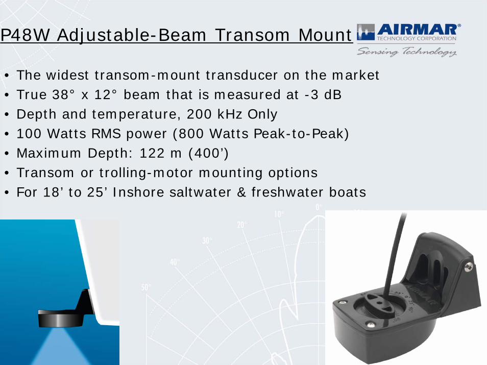
P48W Adjustable-Beam Transom Mount
• The widest transom-mount transducer on the market • True 38° x 12° beam that is measured at -3 dB • Depth and temperature, 200 kHz Only • 100 Watts RMS power (800 Watts Peak-to-Peak) • Maximum Depth: 122 m (400’)• Transom or trolling-motor mounting options • For 18’ to 25’ Inshore saltwater & freshwater boats
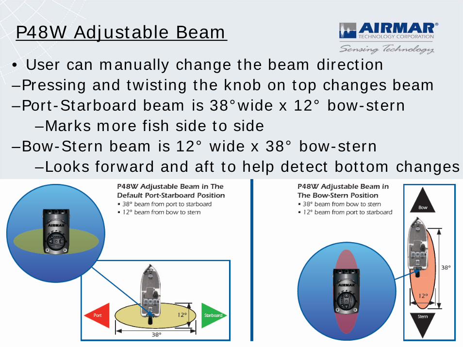
P48W Adjustable Beam
• User can manually change the beam direction–Pressing and twisting the knob on top changes beam –Port-Starboard beam is 38°wide x 12° bow-stern
–Marks more fish side to side–Bow-Stern beam is 12° wide x 38° bow-stern
–Looks forward and aft to help detect bottom changes
Installation-Specific Products
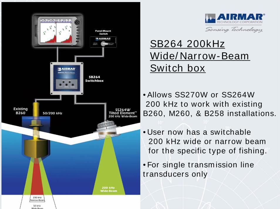
SB264 200kHz Wide/Narrow-Beam Switch box
•Allows SS270W or SS264W200 kHz to work with existing B260, M260, & B258 installations.
•User now has a switchable 200 kHz wide or narrow beam for the specific type of fishing.
•For single transmission line transducers only
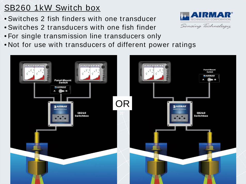
SB260 1kW Switch box•Switches 2 fish finders with one transducer•Switches 2 transducers with one fish finder•For single transmission line transducers only•Not for use with transducers of different power ratings
OR
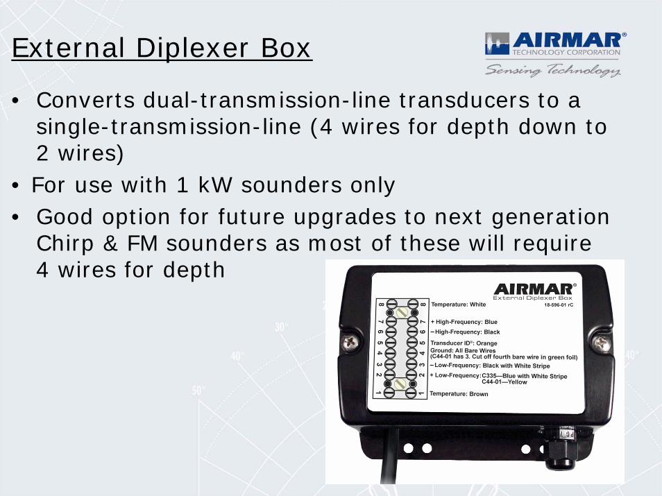
External Diplexer Box
• Converts dual-transmission-line transducers to a single-transmission-line (4 wires for depth down to 2 wires)
• For use with 1 kW sounders only• Good option for future upgrades to next generation
Chirp & FM sounders as most of these will require 4 wires for depth
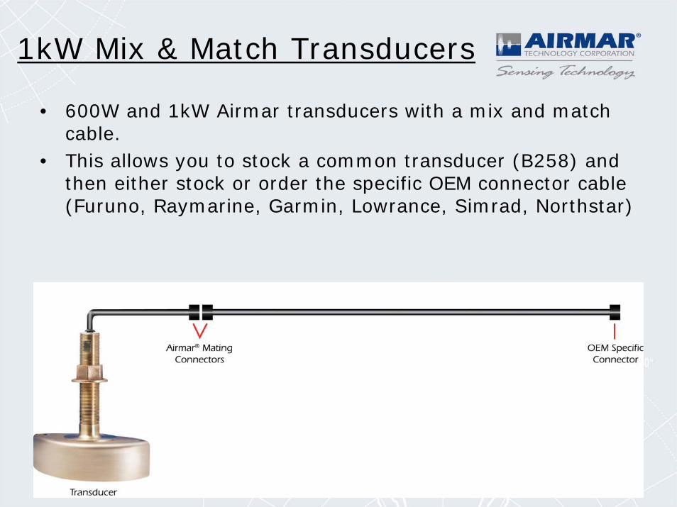
1kW Mix & Match Transducers
• 600W and 1kW Airmar transducers with a mix and match cable.
• This allows you to stock a common transducer (B258) and then either stock or order the specific OEM connector cable (Furuno, Raymarine, Garmin, Lowrance, Simrad, Northstar)
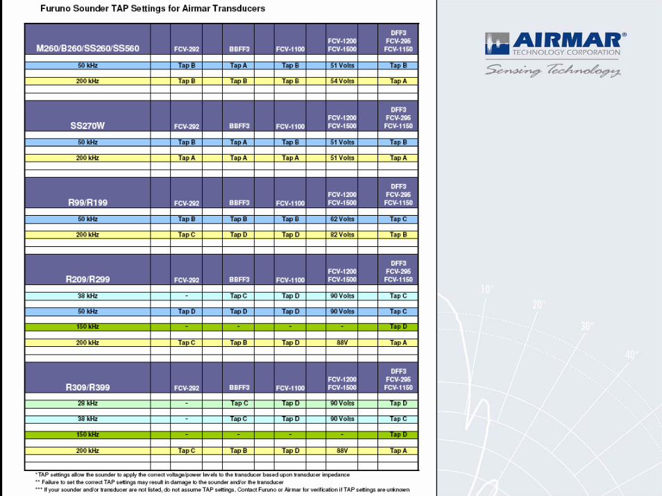
Converting Transducers to Different Manufacturer’s Equipment
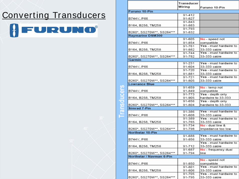
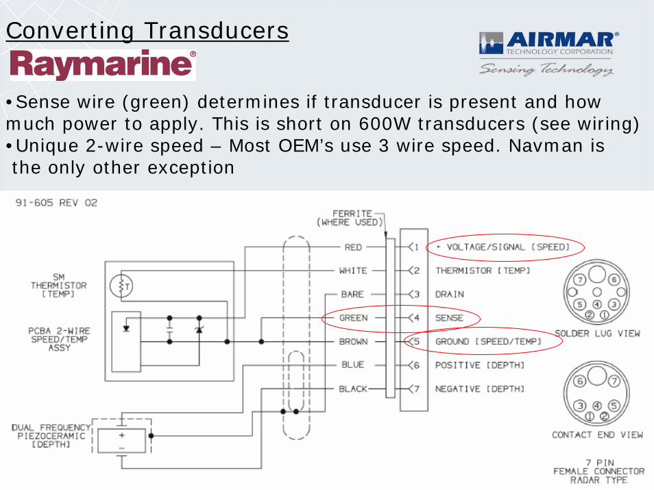
Converting Transducers
Converting Transducers
•Sense wire (green) determines if transducer is present and how much power to apply. This is short on 600W transducers (see wiring)•Unique 2-wire speed – Most OEM’s use 3 wire speed. Navman isthe only other exception
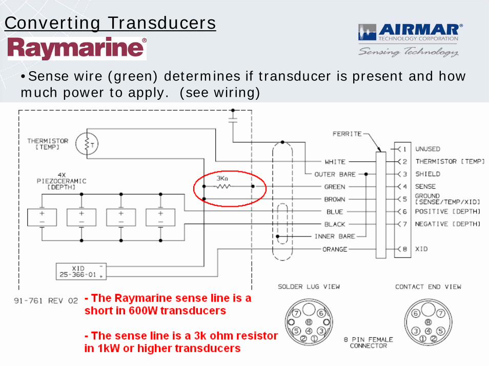
Converting Transducers
•Sense wire (green) determines if transducer is present and how much power to apply. (see wiring)
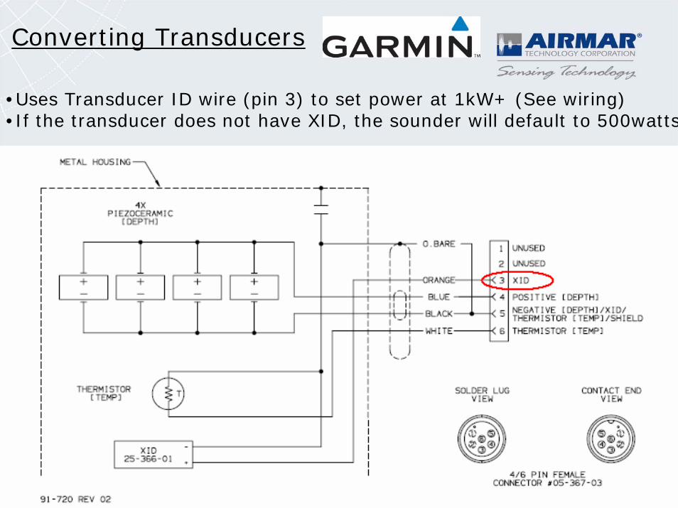
Converting Transducers
•Uses Transducer ID wire (pin 3) to set power at 1kW+ (See wiring)•If the transducer does not have XID, the sounder will default to 500watts
Converting Transducers
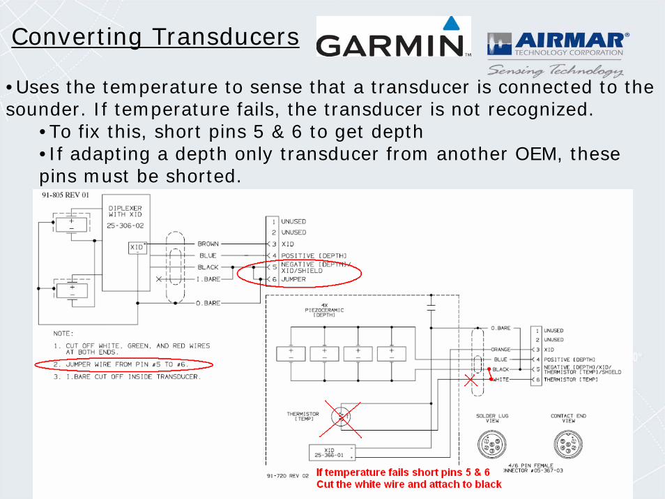
•Uses the temperature to sense that a transducer is connected to the sounder. If temperature fails, the transducer is not recognized.
•To fix this, short pins 5 & 6 to get depth•If adapting a depth only transducer from another OEM, these pins must be shorted.
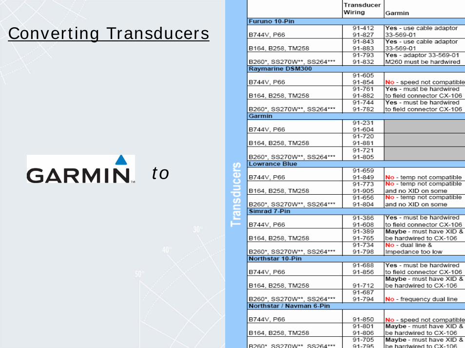
Converting Transducers
to
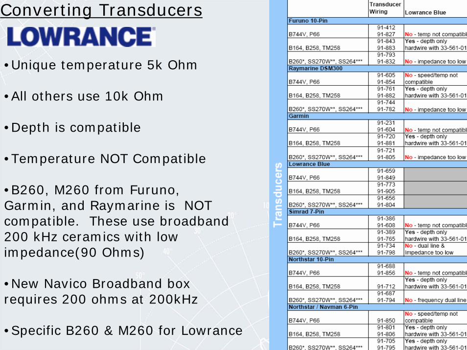
Converting Transducers
•Unique temperature 5k Ohm
•All others use 10k Ohm
•Depth is compatible
•Temperature NOT Compatible
•B260, M260 from Furuno, Garmin, and Raymarine is NOT compatible. These use broadband200 kHz ceramics with low impedance(90 Ohms)
•New Navico Broadband boxrequires 200 ohms at 200kHz
•Specific B260 & M260 for Lowrance
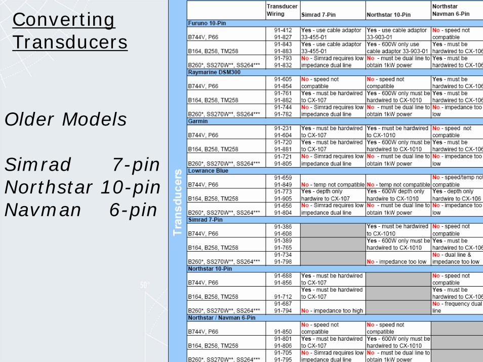
Converting Transducers
Older Models
Simrad 7-pin Northstar 10-pinNavman 6-pin
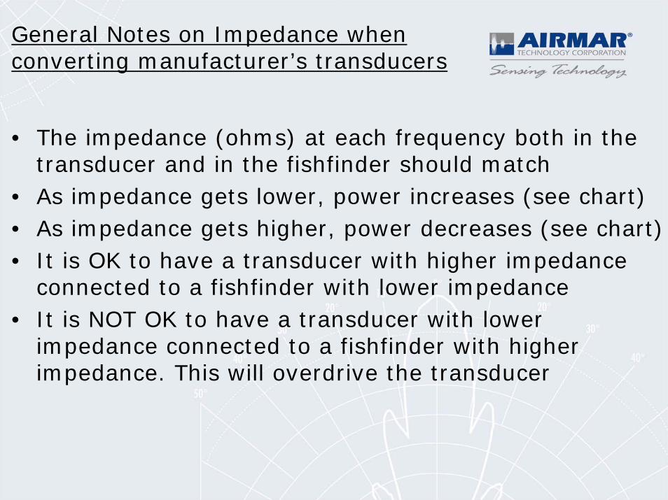
General Notes on Impedance when converting manufacturer’s transducers
• The impedance (ohms) at each frequency both in the transducer and in the fishfinder should match
• As impedance gets lower, power increases (see chart)• As impedance gets higher, power decreases (see chart)• It is OK to have a transducer with higher impedance
connected to a fishfinder with lower impedance• It is NOT OK to have a transducer with lower
impedance connected to a fishfinder with higher impedance. This will overdrive the transducer
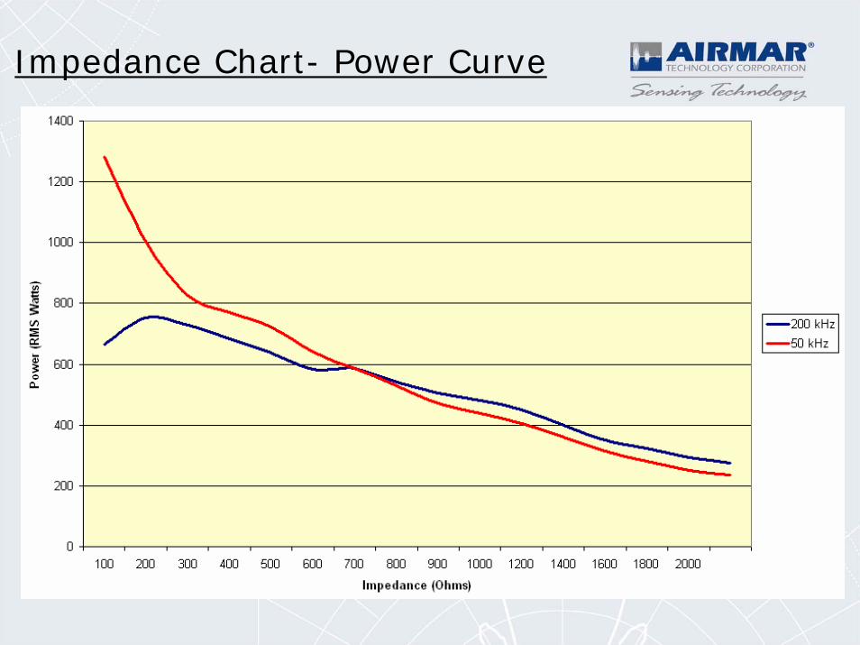
Impedance Chart- Power Curve
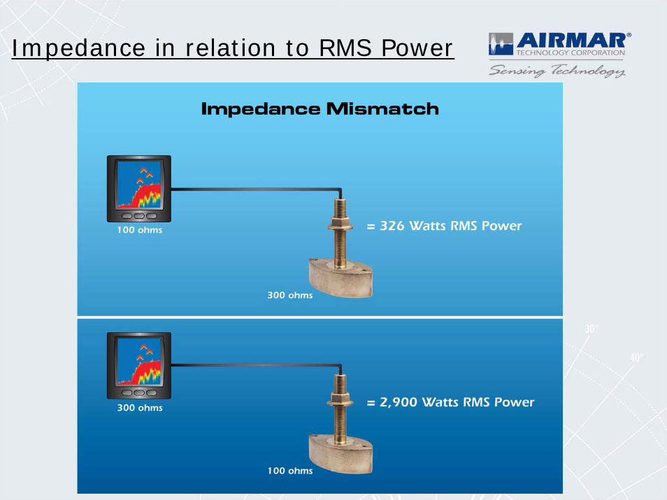
Impedance in relation to RMS Power
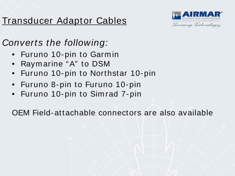
Transducer Adaptor Cables
Converts the following:• Furuno 10-pin to Garmin• Raymarine “A” to DSM• Furuno 10-pin to Northstar 10-pin• Furuno 8-pin to Furuno 10-pin• Furuno 10-pin to Simrad 7-pin
OEM Field-attachable connectors are also available
Installation & Troubleshooting
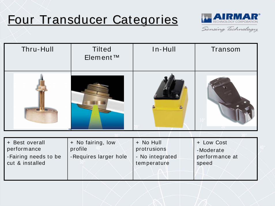
Four Transducer CategoriesFour Transducer Categories
Thru-Hull Tilted Element™
In-Hull Transom
+ Best overall performance-Fairing needs to be cut & installed
+ No fairing, low profile-Requires larger hole
+ No Hull protrusions- No integrated temperature
+ Low Cost-Moderate performance at speed
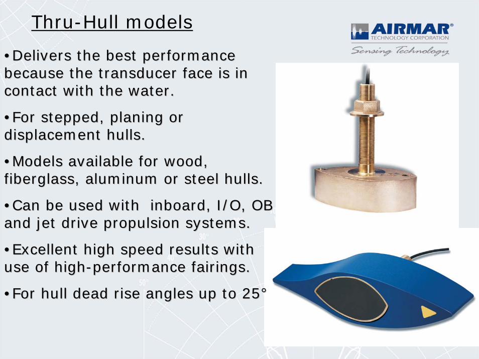
••Delivers the best performance Delivers the best performance because the transducer face is in because the transducer face is in contact with the water.contact with the water.
••For stepped, planing or For stepped, planing or displacement hulls. displacement hulls.
••Models available for wood, Models available for wood, fiberglass, aluminum or steel hulls.fiberglass, aluminum or steel hulls.
••Can be used with inboard, I/O, OB Can be used with inboard, I/O, OB and jet drive propulsion systems.and jet drive propulsion systems.
••Excellent high speed results with Excellent high speed results with use of highuse of high--performance fairings.performance fairings.
••For hull dead rise angles up to 25°For hull dead rise angles up to 25°
Thru-Hull models
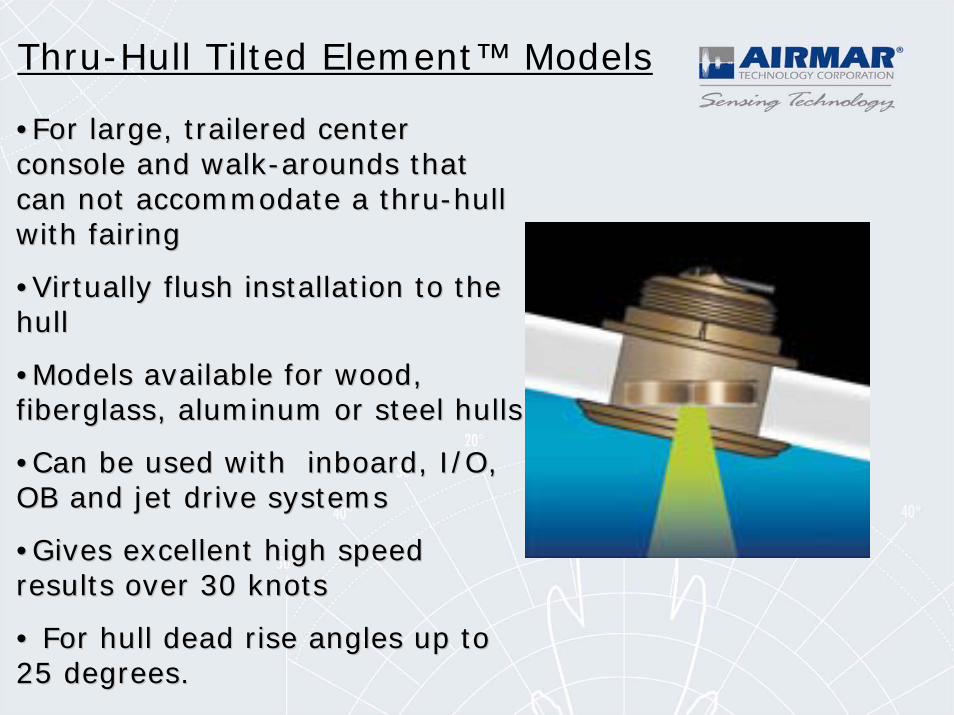
••For large, trailered center For large, trailered center console and walkconsole and walk--arounds that arounds that can not accommodate a thrucan not accommodate a thru--hull hull with fairingwith fairing
••Virtually flush installation to the Virtually flush installation to the hullhull
••Models available for wood, Models available for wood, fiberglass, aluminum or steel hullsfiberglass, aluminum or steel hulls
••Can be used with inboard, I/O, Can be used with inboard, I/O, OB and jet drive systemsOB and jet drive systems
••Gives excellent high speed Gives excellent high speed results over 30 knotsresults over 30 knots
•• For hull dead rise angles up to For hull dead rise angles up to 25 degrees.25 degrees.
Thru-Hull Tilted Element™ Models
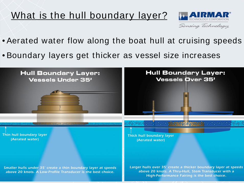
What is the hull boundary layer?
•Aerated water flow along the boat hull at cruising speeds
•Boundary layers get thicker as vessel size increases
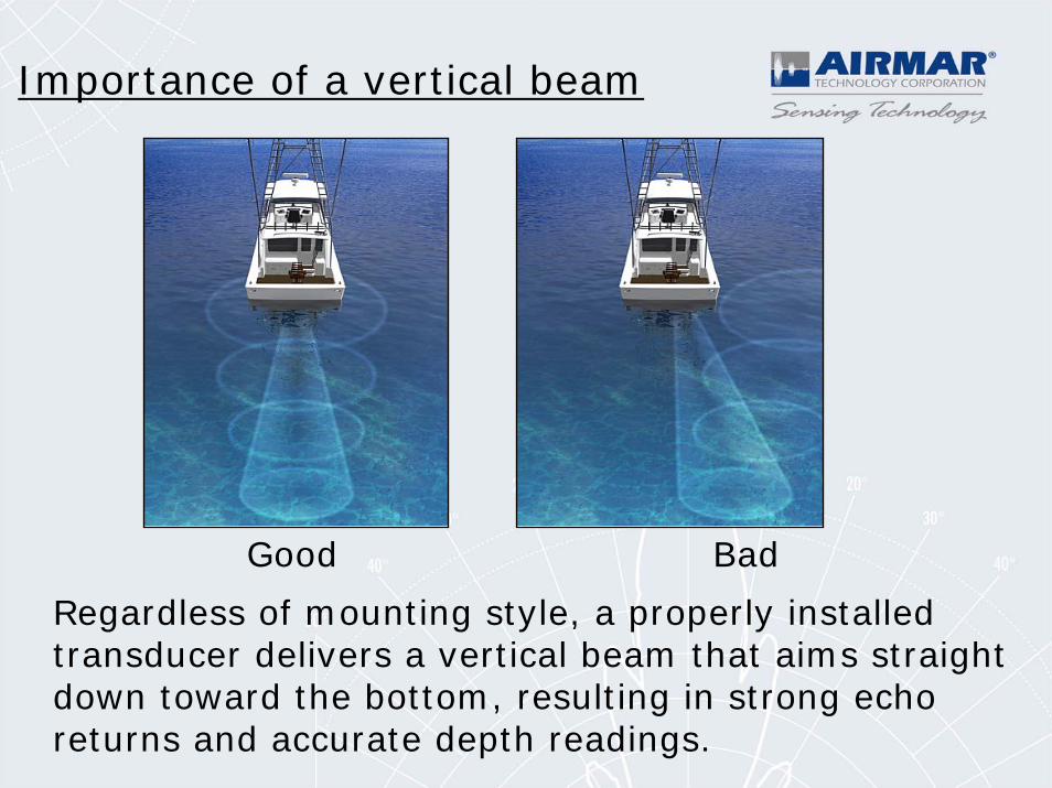
Importance of a vertical beam
Regardless of mounting style, a properly installed transducer delivers a vertical beam that aims straight down toward the bottom, resulting in strong echo returns and accurate depth readings.
Good Bad
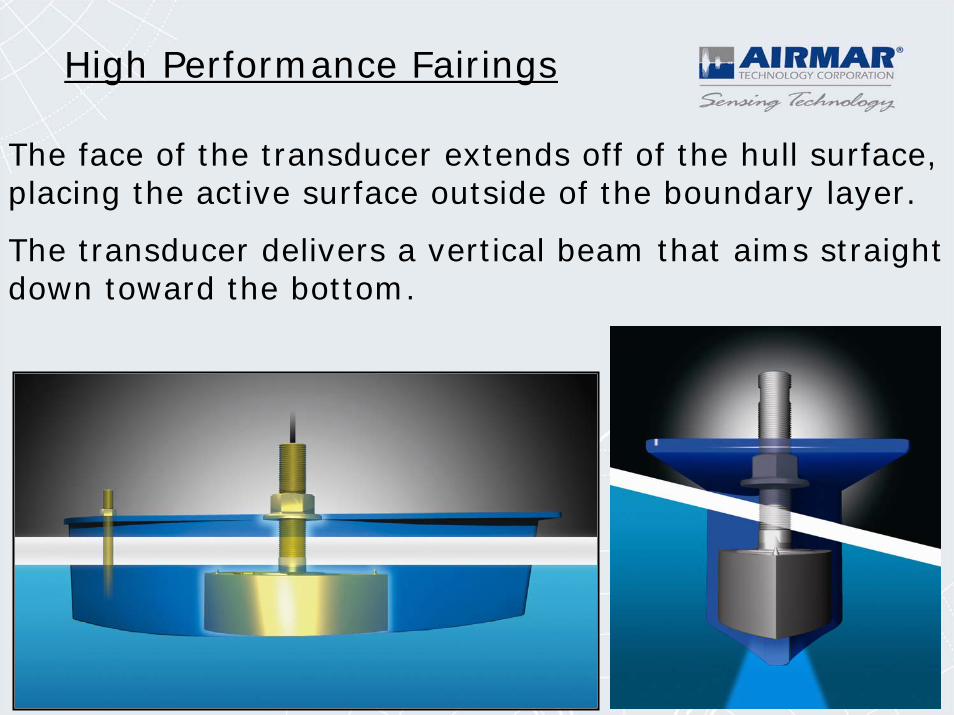
High Performance Fairings
The face of the transducer extends off of the hull surface, placing the active surface outside of the boundary layer.
The transducer delivers a vertical beam that aims straight down toward the bottom.
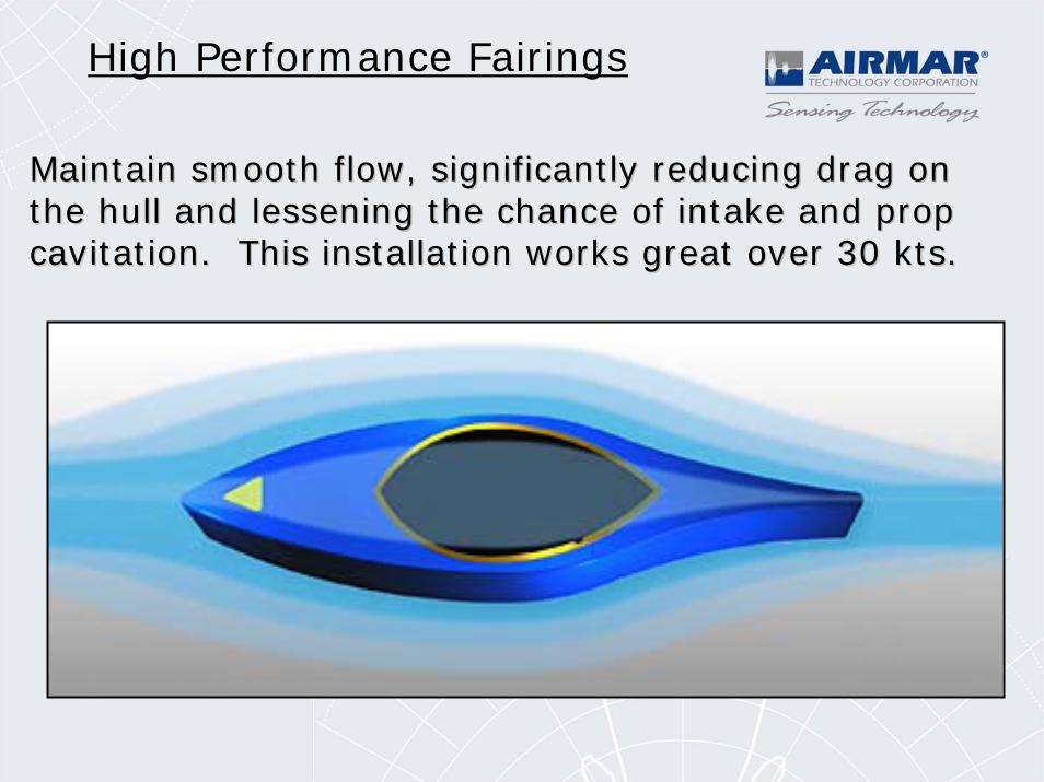
High Performance Fairings
Maintain smooth flow, significantly reducing drag on Maintain smooth flow, significantly reducing drag on the hull and lessening the chance of intake and prop the hull and lessening the chance of intake and prop cavitation. This installation works great over 30 kts.cavitation. This installation works great over 30 kts.
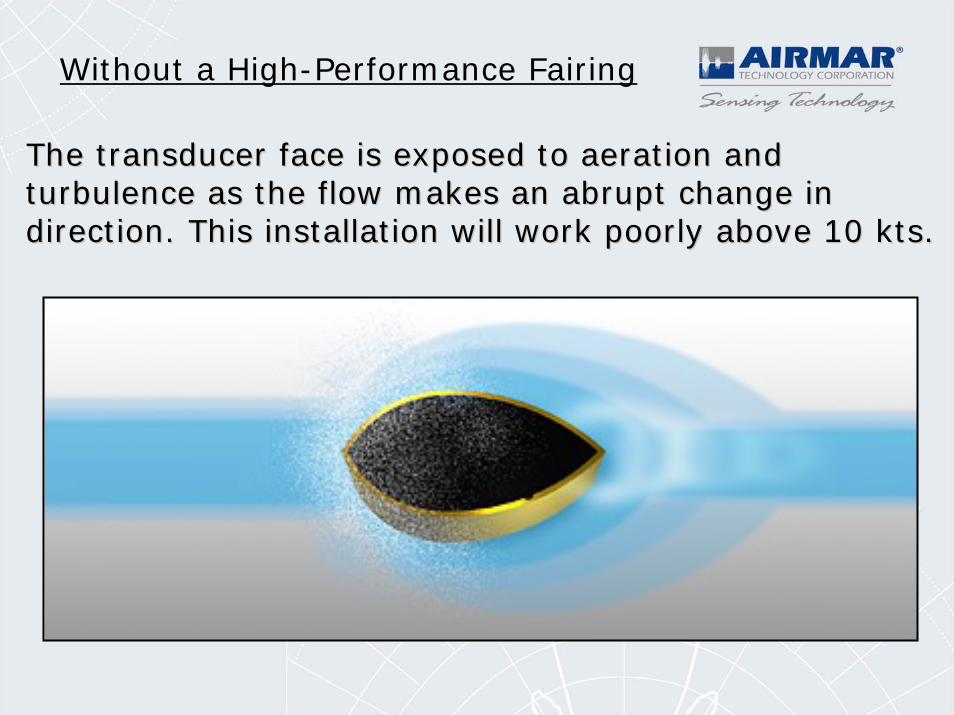
Without a High-Performance Fairing
The transducer face is exposed to aeration and The transducer face is exposed to aeration and turbulence as the flow makes an abrupt change in turbulence as the flow makes an abrupt change in direction. This installation will work poorly above 10 kts.direction. This installation will work poorly above 10 kts.
Installation & TroubleshootingBasics: Mounting Location
• The water flowing across the hull must be smooth with aminimum of bubbles and turbulence (especially at high speeds).•DO NOT MOUNT near water intake or dischargeopenings or behind strakes, fittings, or hull irregularities.• The transducer must be continuously immersed in water.• The transducer beam must be unobstructed by the keel or propeller shaft(s).• Choose a location away from interference caused by power and radiation sources such as: the propeller(s) and shaft(s), other machinery, other echosounders, and other cables. The lower the noise level, the higher the echosounder gain setting that can beused.• Choose a location with a minimum deadrise angle.• Choose an accessible spot inside the vessel with adequate headroom for the height of the housing, tightening the nuts, andremoving the insert.
• Always choose a location away from interference caused by sources such as propeller shafts, satellite or radar equipment, other machinery and cable runs.
• The lower the overall noise level around the transducer and cable, the higher the gain setting that can be used, resulting in more screen detail.
• If screen interference appears at a specific rpm or when the boat is put in and out of gear, this could be a sign of electrical interference on the sounder’s power line. Try powering the sounder directly from a stand-alone battery.
• If the screen interference increases proportional to vessel speed this usually indicates that the transducer face is exposed to aerated water.
Avoiding Interference
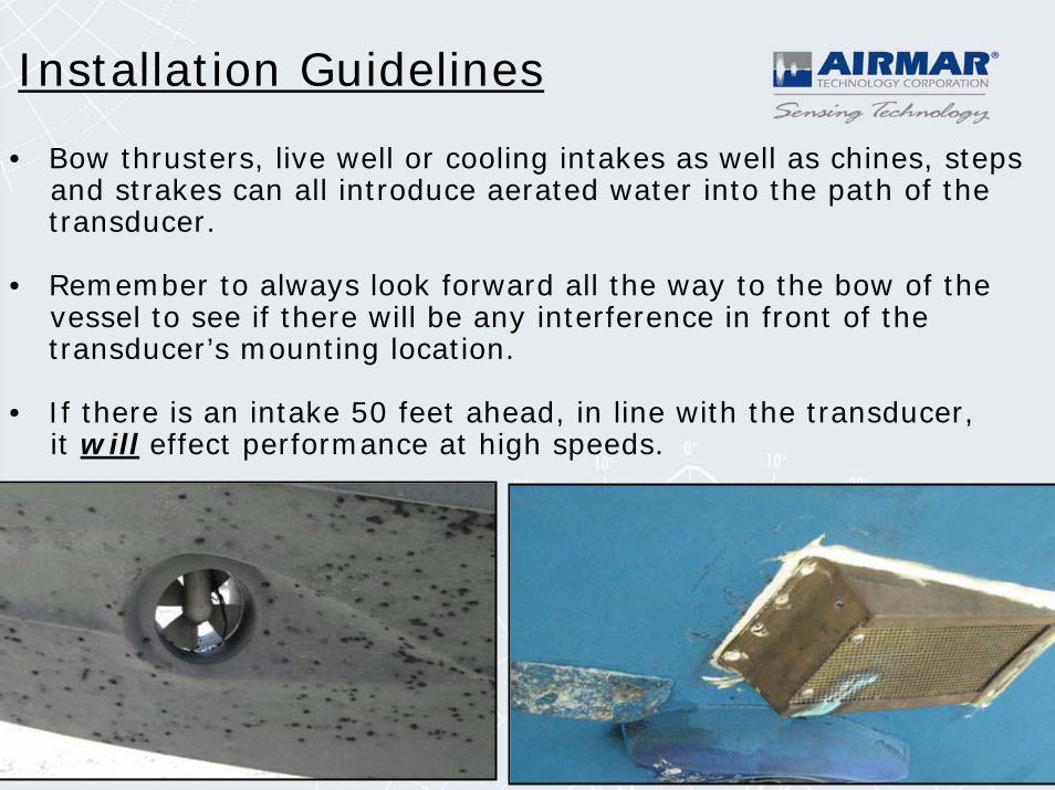
• Bow thrusters, live well or cooling intakes as well as chines, steps and strakes can all introduce aerated water into the path of the transducer.
• Remember to always look forward all the way to the bow of the vessel to see if there will be any interference in front of the transducer’s mounting location.
• If there is an intake 50 feet ahead, in line with the transducer, it will effect performance at high speeds.
Installation Guidelines
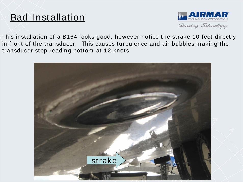
This installation of a B164 looks good, however notice the strake 10 feet directly in front of the transducer. This causes turbulence and air bubbles making the transducer stop reading bottom at 12 knots.
strake
Bad Installation
Bad Installation
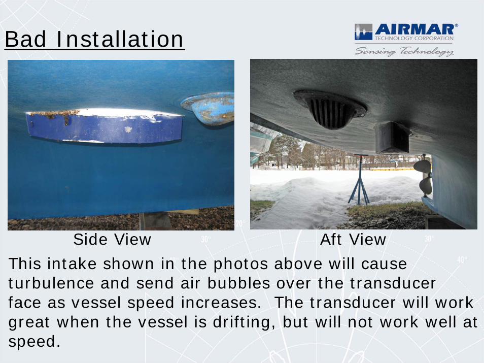
Side View Aft ViewThis intake shown in the photos above will cause turbulence and send air bubbles over the transducer face as vessel speed increases. The transducer will work great when the vessel is drifting, but will not work well at speed.
Bad Installation
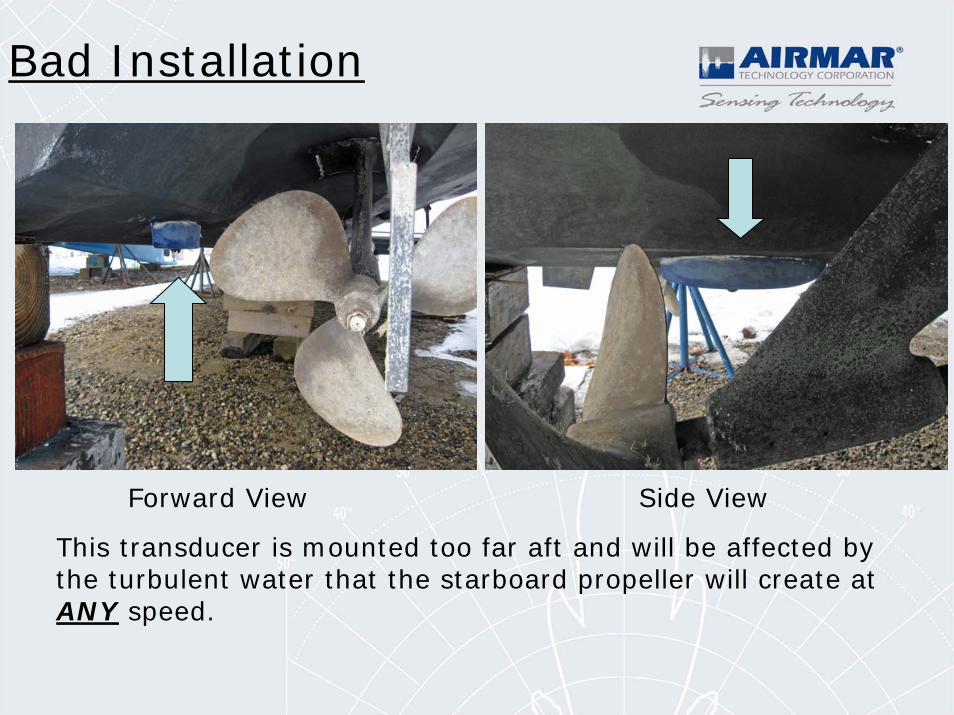
Forward View Side View
This transducer is mounted too far aft and will be affected by the turbulent water that the starboard propeller will create at ANY speed.
Good Installation
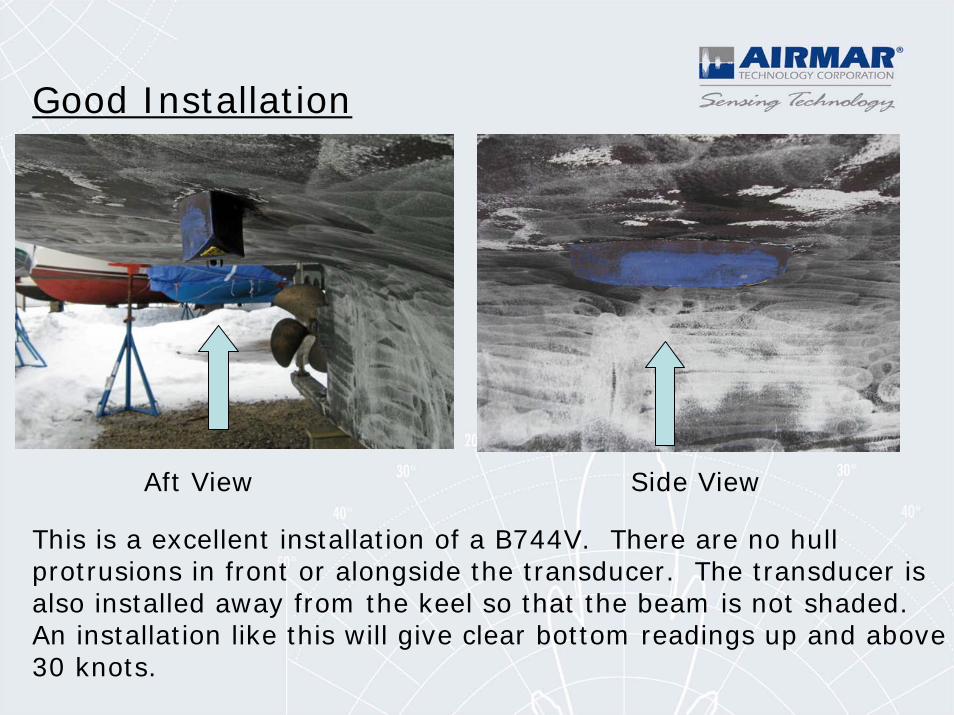
This is a excellent installation of a B744V. There are no hull protrusions in front or alongside the transducer. The transducer is also installed away from the keel so that the beam is not shaded.An installation like this will give clear bottom readings up and above 30 knots.
Aft View Side View
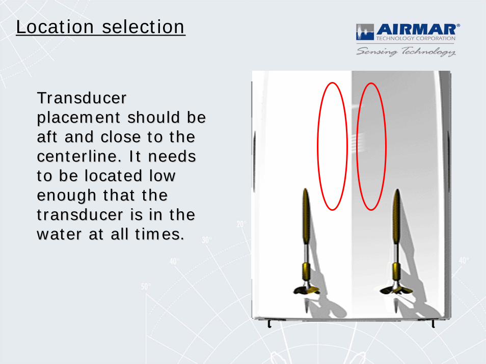
Location selection
Transducer Transducer placement should be placement should be aft and close to the aft and close to the centerline. It needs centerline. It needs to be located low to be located low enough that the enough that the transducer is in the transducer is in the water at all times.water at all times.
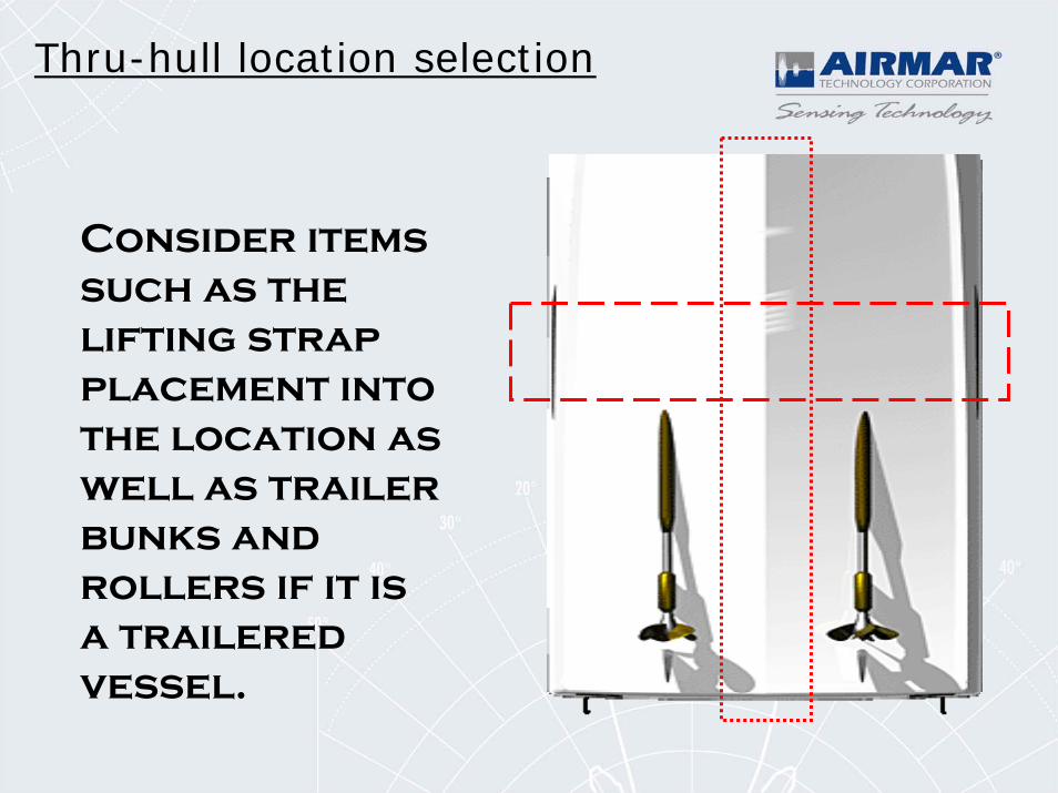
Consider items such as the lifting strap placement into the location as well as trailer bunks and rollers if it is a trailered vessel.
Thru-hull location selection
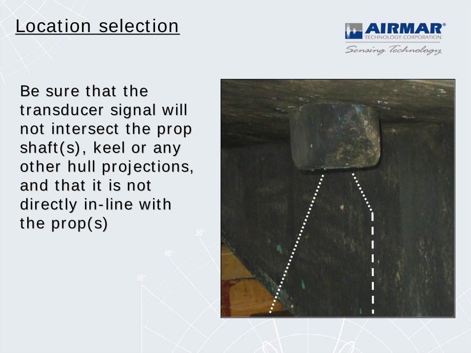
Location selection
Be sure that the Be sure that the transducer signal will transducer signal will not intersect the prop not intersect the prop shaft(s), keel or any shaft(s), keel or any other hull projections, other hull projections, and that it is not and that it is not directly indirectly in--line with line with the prop(s)the prop(s)
BOWBOW
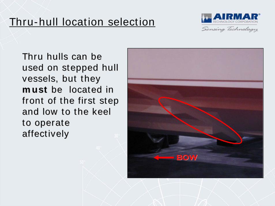
Thru-hull location selection
Thru hulls can be Thru hulls can be used on stepped hull used on stepped hull vessels, but they vessels, but they mustmust be located in be located in front of the first step front of the first step and low to the keel and low to the keel to operate to operate affectively affectively
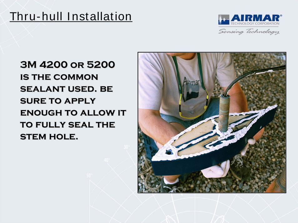
Thru-hull Installation
3M 4200 or 5200 3M 4200 or 5200 is the common is the common sealant used. be sealant used. be sure to apply sure to apply enough to allow it enough to allow it to fully seal the to fully seal the stem hole. stem hole.
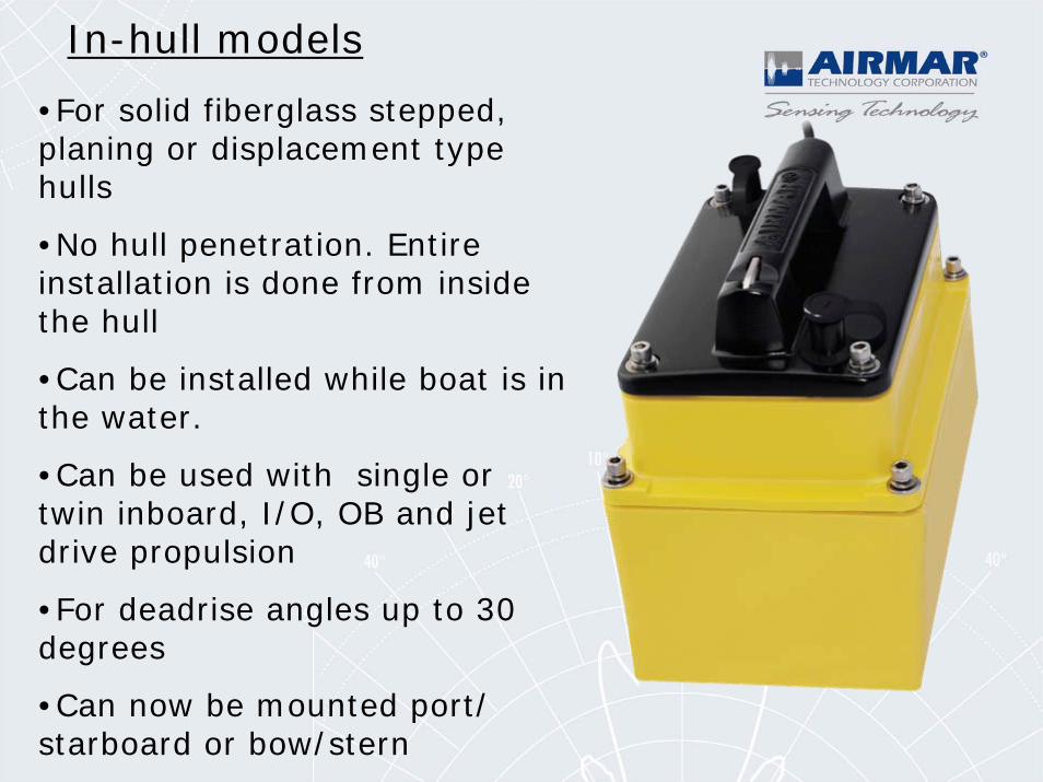
•For solid fiberglass stepped, planing or displacement type hulls
•No hull penetration. Entire installation is done from inside the hull
•Can be installed while boat is in the water.
•Can be used with single or twin inboard, I/O, OB and jet drive propulsion
•For deadrise angles up to 30 degrees
•Can now be mounted port/ starboard or bow/stern
In-hull models
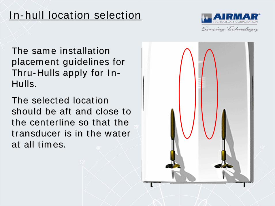
In-hull location selection
The same installation The same installation placement guidelines for placement guidelines for ThruThru--Hulls apply for InHulls apply for In--Hulls.Hulls.
The selected location The selected location should be aft and close to should be aft and close to the centerline so that the the centerline so that the transducer is in the water transducer is in the water at all times.at all times.
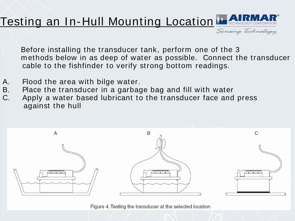
Testing an In-Hull Mounting Location
Before installing the transducer tank, perform one of the 3 methods below in as deep of water as possible. Connect the transducer cable to the fishfinder to verify strong bottom readings.
A. Flood the area with bilge water.B. Place the transducer in a garbage bag and fill with waterC. Apply a water based lubricant to the transducer face and press
against the hull
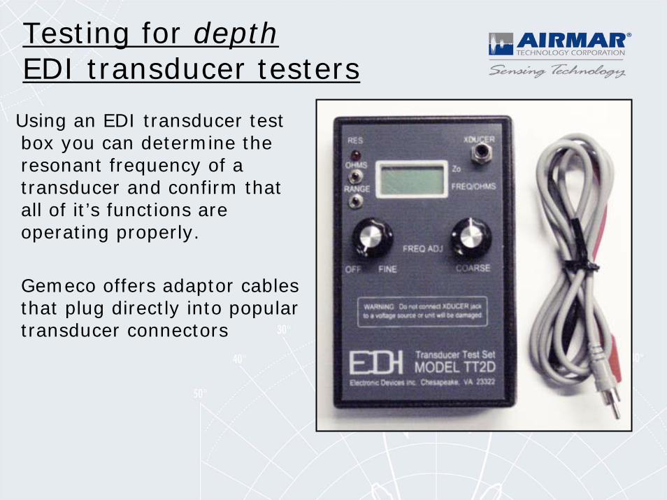
Using an EDI transducer test box you can determine the resonant frequency of a transducer and confirm that all of it’s functions are operating properly.
Gemeco offers adaptor cables that plug directly into popular transducer connectors
Testing for depthEDI transducer testers
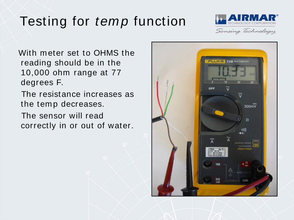
With meter set to OHMS the reading should be in the 10,000 ohm range at 77 degrees F. The resistance increases as the temp decreases. The sensor will read correctly in or out of water.
Testing for temp function
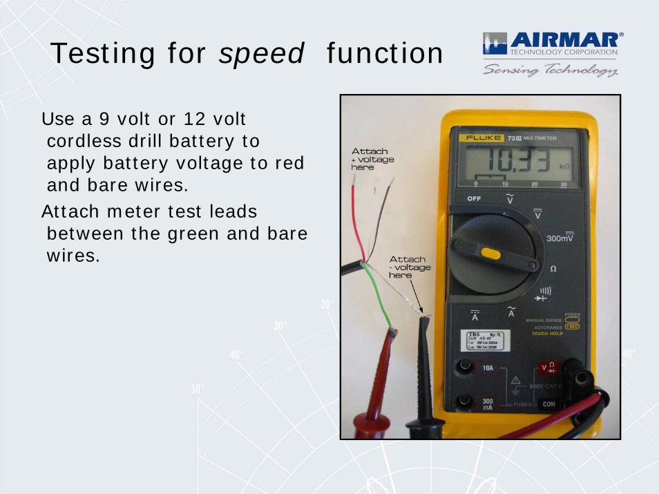
Use a 9 volt or 12 volt cordless drill battery to apply battery voltage to red and bare wires. Attach meter test leads between the green and bare wires.
Testing for speed function
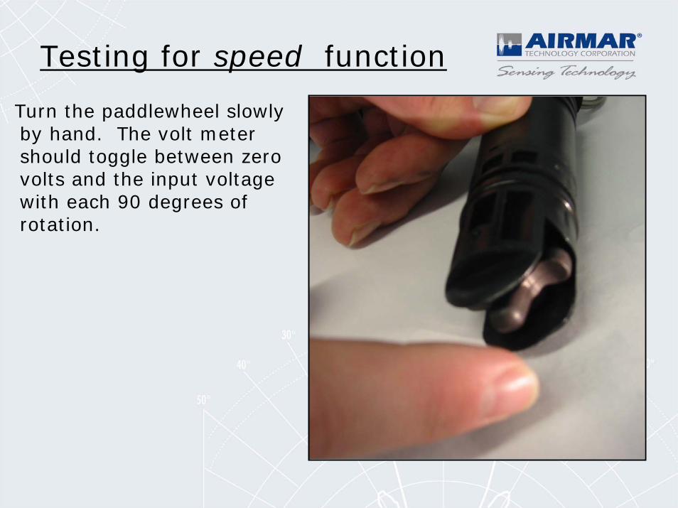
Turn the paddlewheel slowly by hand. The volt meter should toggle between zero volts and the input voltage with each 90 degrees of rotation.
Testing for speed function
In Hull Transducers
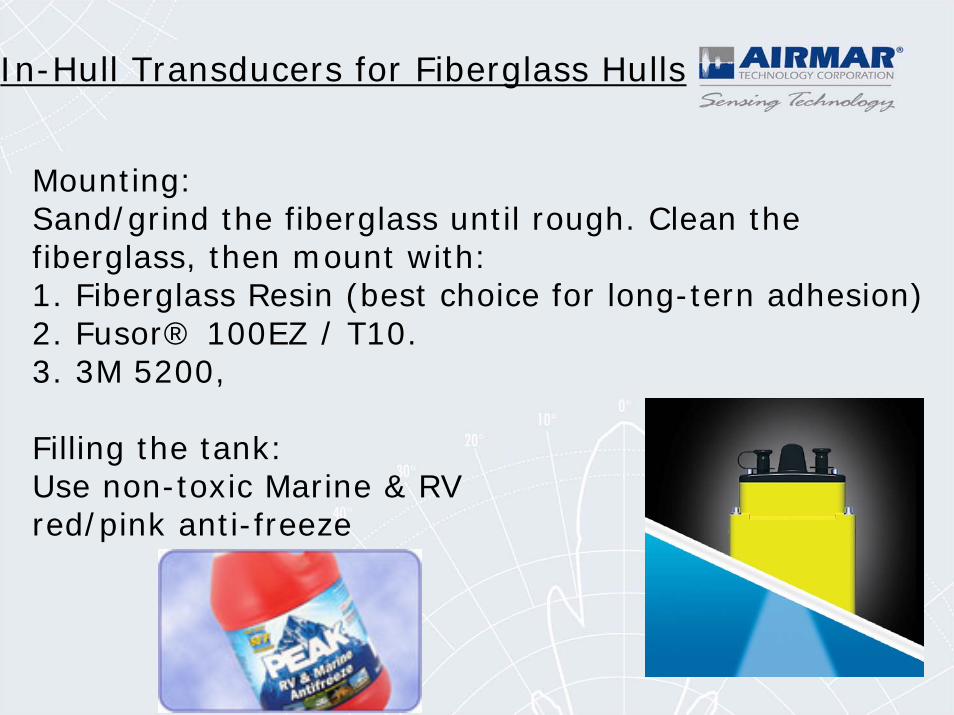
In-Hull Transducers for Fiberglass Hulls
Mounting:Sand/grind the fiberglass until rough. Clean the fiberglass, then mount with:1. Fiberglass Resin (best choice for long-tern adhesion)2. Fusor® 100EZ / T10. 3. 3M 5200,
Filling the tank:Use non-toxic Marine & RV red/pink anti-freeze
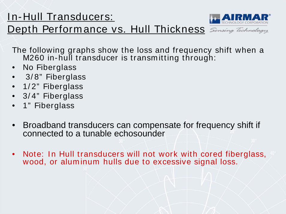
The following graphs show the loss and frequency shift when a M260 in-hull transducer is transmitting through:
• No Fiberglass• 3/8” Fiberglass• 1/2” Fiberglass• 3/4” Fiberglass• 1” Fiberglass
• Broadband transducers can compensate for frequency shift if connected to a tunable echosounder
• Note: In Hull transducers will not work with cored fiberglass, wood, or aluminum hulls due to excessive signal loss.
In-Hull Transducers:Depth Performance vs. Hull Thickness
155
156
157
158
159
160
161
162
163
164
0" FIBERGLASS 3/8" FIBERGLASS 1/2" FIBERGLASS 3/4" FIBERGLASS 1" FIBERGLASS
HULL THICKNESS
TVR
(dB
)
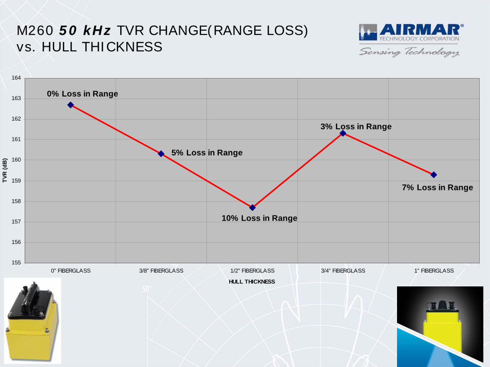
0% Loss in Range
10% Loss in Range
5% Loss in Range
3% Loss in Range
7% Loss in Range
M260 50 kHz TVR CHANGE(RANGE LOSS)vs. HULL THICKNESS
40
42
44
46
48
50
52
54
56
0" FIBERGLASS 3/8" FIBERGLASS 1/2" FIBERGLASS 3/4" FIBERGLASS 1" FIBERGLASS
HULL THICKNESS
kHz
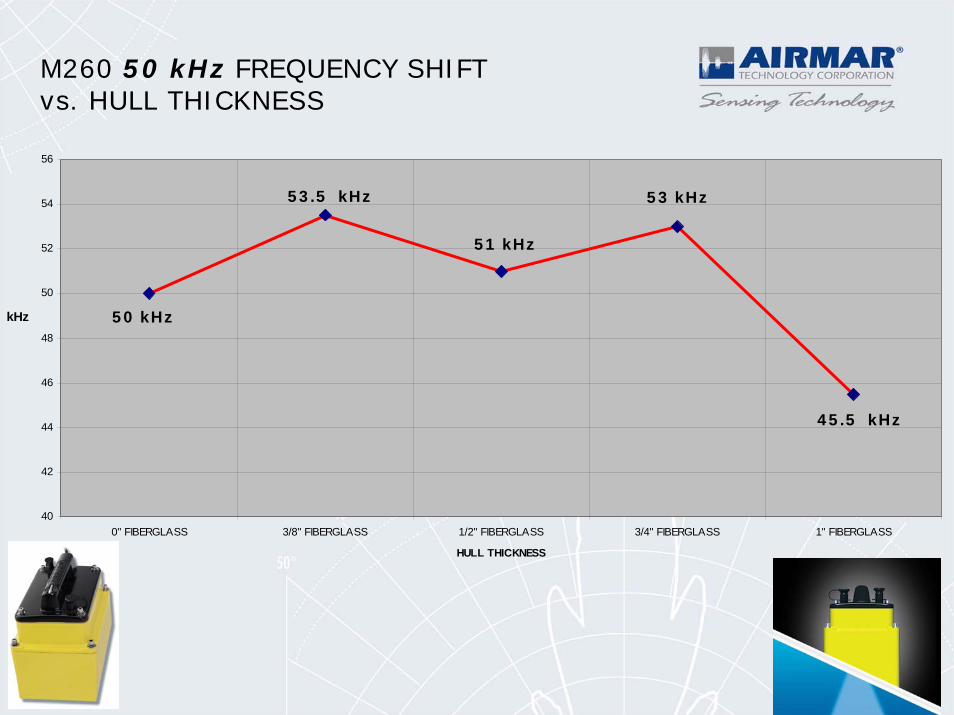
M260 50 kHz FREQUENCY SHIFTvs. HULL THICKNESS
50 kHz
53.5 kHz
51 kHz
53 kHz
45.5 kHz
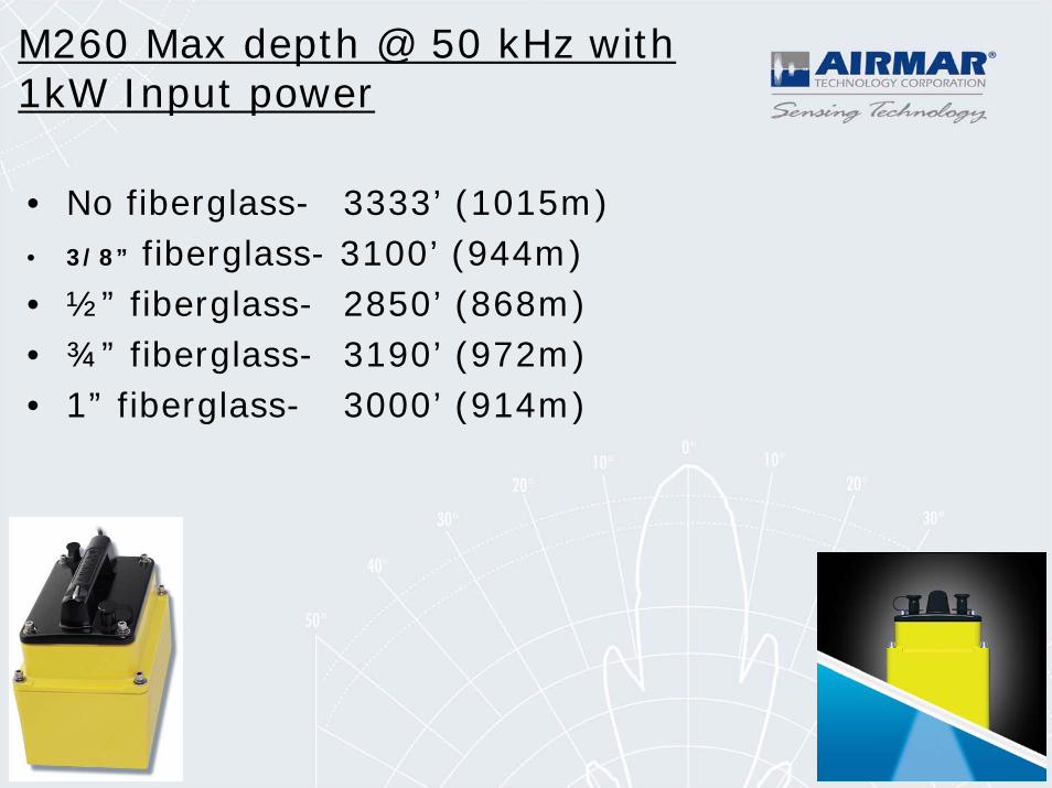
M260 Max depth @ 50 kHz with 1kW Input power
• No fiberglass- 3333’ (1015m)• 3/8” fiberglass- 3100’ (944m)• ½” fiberglass- 2850’ (868m)• ¾” fiberglass- 3190’ (972m)• 1” fiberglass- 3000’ (914m)
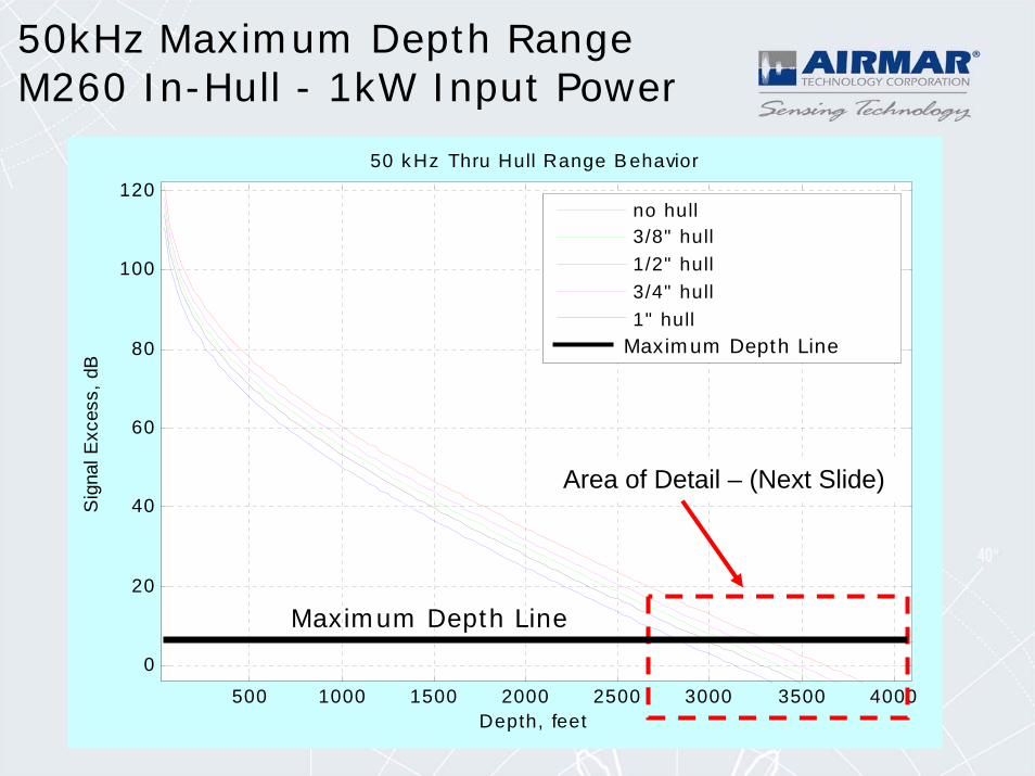
50kHz Maximum Depth RangeM260 In-Hull - 1kW Input Power
500 1000 1500 2000 2500 3000 3500 4000
0
20
40
60
80
100
120
Depth, feet
Sig
nal E
xces
s, d
B
50 k Hz Thru Hull Range B ehavior
no hull3/8" hull1/2" hull3/4" hull1" hull+ 6 dB detec tion thres hold
Area of Detail – (Next Slide)
Maximum Depth Line
Maximum Depth Line
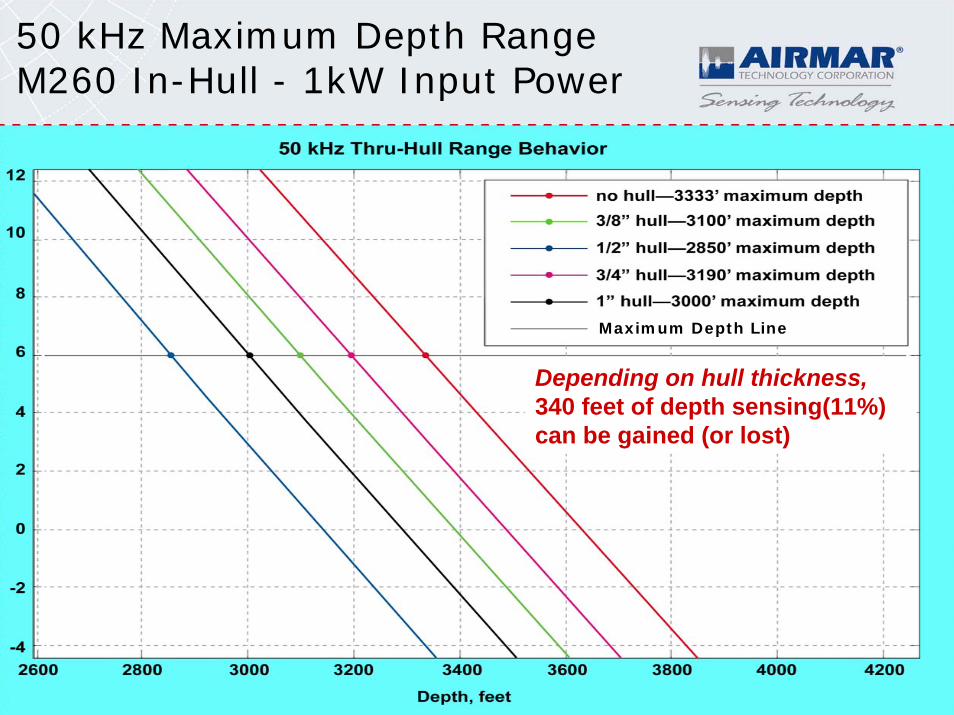
50 kHz Maximum Depth RangeM260 In-Hull - 1kW Input Power
Depending on hull thickness,340 feet of depth sensing(11%) can be gained (or lost)
Maximum Depth Line
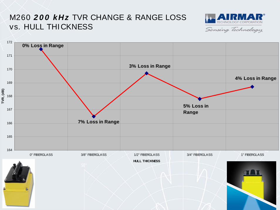
164
165
166
167
168
169
170
171
172
0" FIBERGLASS 3/8" FIBERGLASS 1/2" FIBERGLASS 3/4" FIBERGLASS 1" FIBERGLASS
HULL THICKNESS
TVR
, (dB
)
7% Loss in Range
3% Loss in Range
5% Loss in Range
4% Loss in Range
0% Loss in Range
M260 200 kHz TVR CHANGE & RANGE LOSSvs. HULL THICKNESS
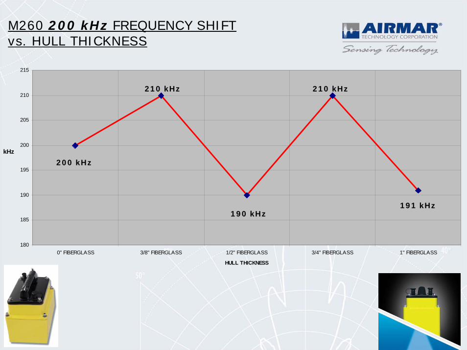
M260 200 kHz FREQUENCY SHIFT vs. HULL THICKNESS
180
185
190
195
200
205
210
215
0" FIBERGLASS 3/8" FIBERGLASS 1/2" FIBERGLASS 3/4" FIBERGLASS 1" FIBERGLASS
HULL THICKNESS
kHz
200 kHz
210 kHz
190 kHz
210 kHz
191 kHz
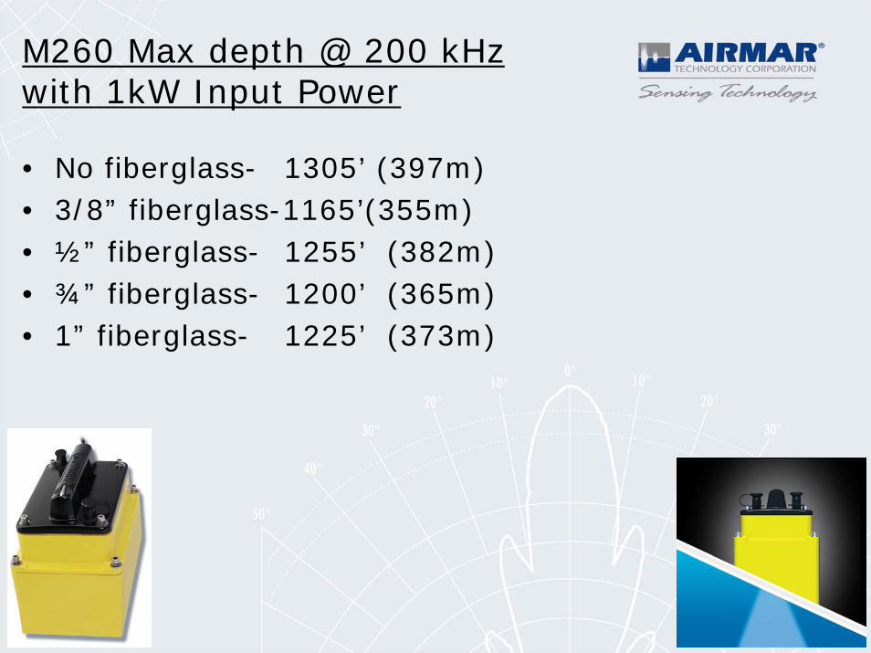
M260 Max depth @ 200 kHz with 1kW Input Power
• No fiberglass- 1305’ (397m)• 3/8” fiberglass-1165’(355m) • ½” fiberglass- 1255’ (382m) • ¾” fiberglass- 1200’ (365m) • 1” fiberglass- 1225’ (373m)
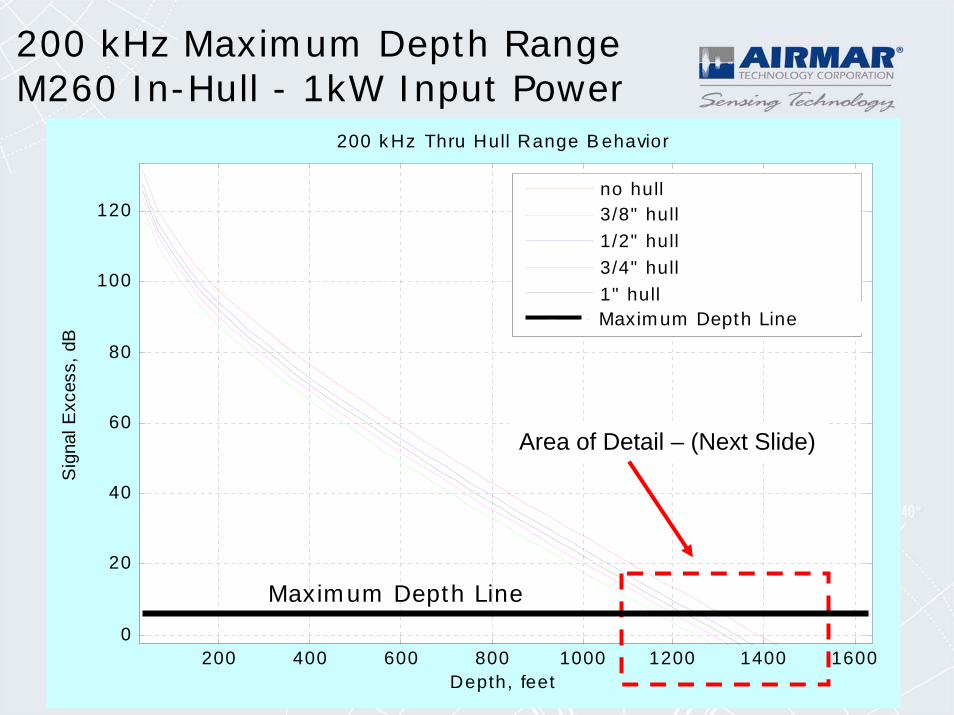
200 kHz Maximum Depth RangeM260 In-Hull - 1kW Input Power
200 400 600 800 1000 1200 1400 16000
20
40
60
80
100
120
Depth, feet
Sig
nal E
xces
s, d
B
200 k Hz Thru Hull Range B ehavior
no hull3/8" hull1/2" hull3/4" hull1" hull+ 6 dB detec t ion thres hold
Area of Detail – (Next Slide)
Maximum Depth Line
Maximum Depth Line
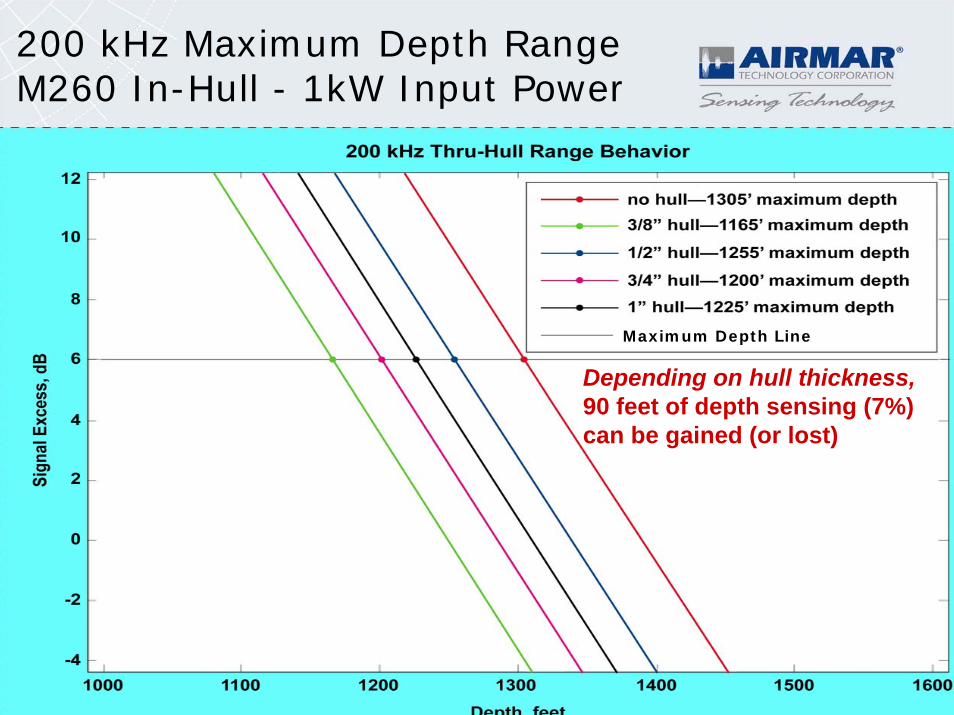
200 kHz Maximum Depth RangeM260 In-Hull - 1kW Input Power
Depending on hull thickness,90 feet of depth sensing (7%) can be gained (or lost)
Maximum Depth Line
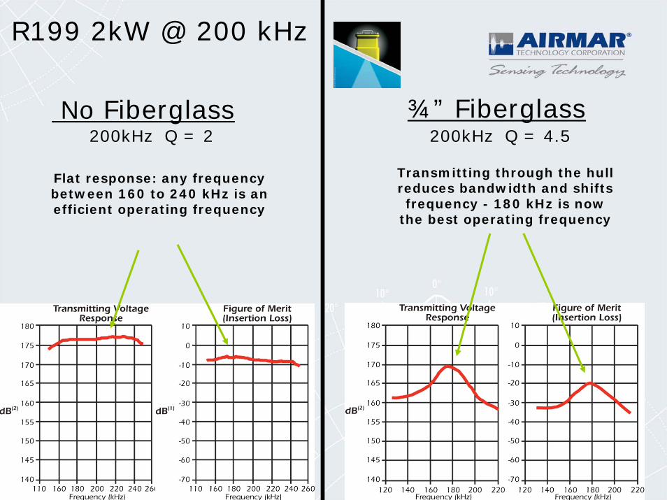
200kHz Q = 2 200kHz Q = 4.5No Fiberglass ¾” Fiberglass
Flat response: any frequency between 160 to 240 kHz is an efficient operating frequency
Transmitting through the hull reduces bandwidth and shifts frequency - 180 kHz is now
the best operating frequency
R199 2kW @ 200 kHz
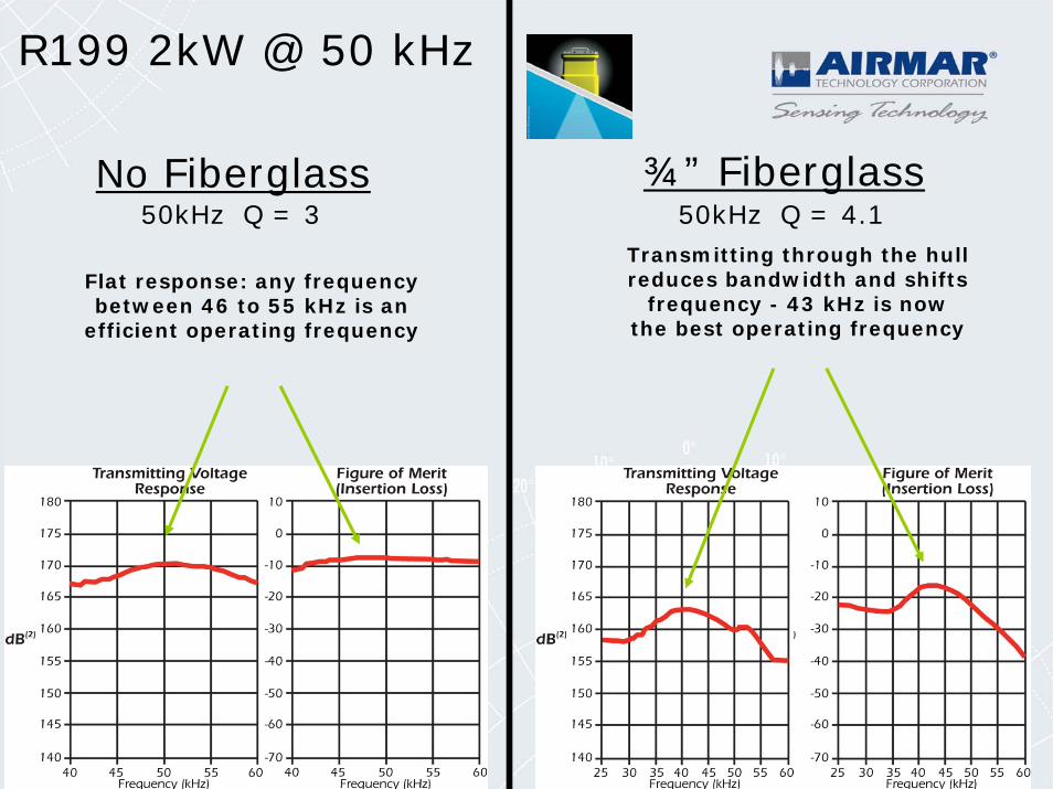
50kHz Q = 3 50kHz Q = 4.1No Fiberglass ¾” Fiberglass
Flat response: any frequency between 46 to 55 kHz is an
efficient operating frequency
Transmitting through the hull reduces bandwidth and shifts
frequency - 43 kHz is now the best operating frequency
R199 2kW @ 50 kHz

Broadband Transducers
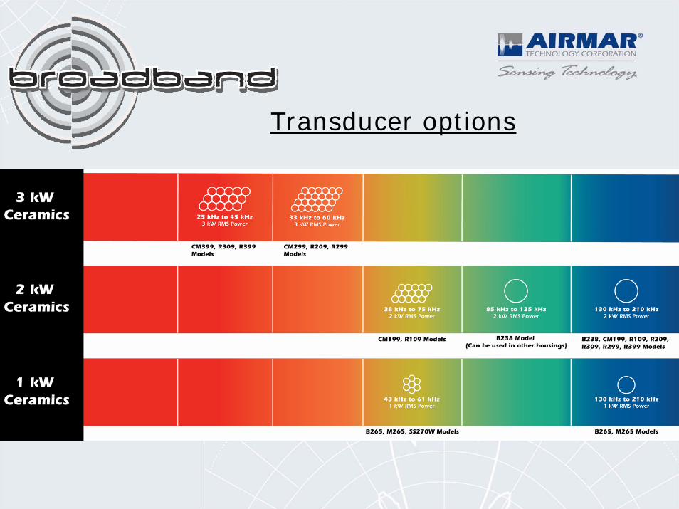
Transducer options
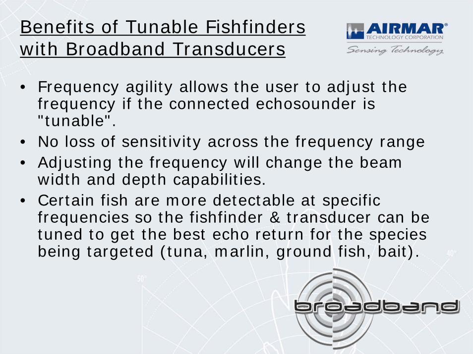
• Frequency agility allows the user to adjust the frequency if the connected echosounder is "tunable".
• No loss of sensitivity across the frequency range• Adjusting the frequency will change the beam
width and depth capabilities. • Certain fish are more detectable at specific
frequencies so the fishfinder & transducer can be tuned to get the best echo return for the species being targeted (tuna, marlin, ground fish, bait).
Benefits of Tunable Fishfinders with Broadband Transducers
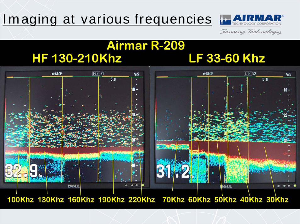
Imaging at various frequencies
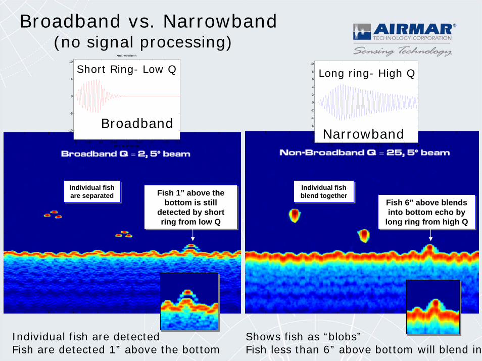
Fish 6” above blends into bottom echo by
long ring from high Q
Fish 6” above blends into bottom echo by
long ring from high Q
Individual fish are detectedFish are detected 1” above the bottom
Shows fish as “blobs”Fish less than 6” above bottom will blend in
0 0.05 0.1 0.15 0.2 0.25 0.3 0.35 0.4-10
-8
-6
-4
-2
0
2
4
6
8
10
ti illi d
Broadband vs. Narrowband(no signal processing)
Fish 1” above the bottom is still
detected by short ring from low Q
Fish 1” above the bottom is still
detected by short ring from low Q
Individual fish blend togetherIndividual fish blend together
Individual fish are separated
Individual fish are separated
Long ring- High Q
0 0.05 0.1 0.15 0.2 0.25 0.3 0.35 0.4
-10
-5
0
5
10
Xmit waveform
time, milliseconds
Short Ring- Low Q
BroadbandNarrowband
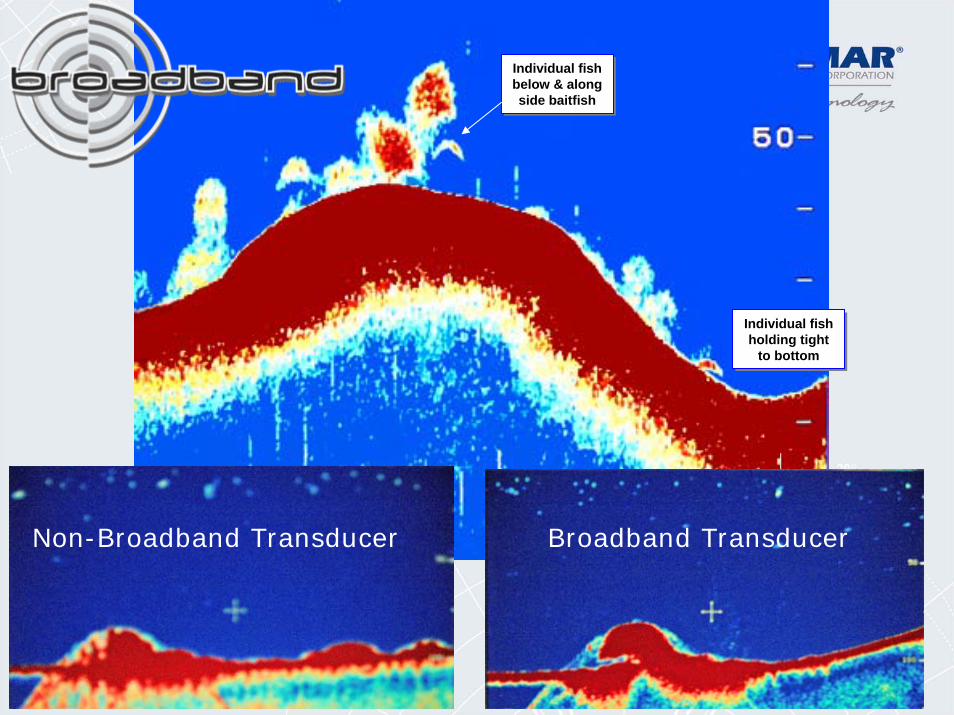
Individual fish below & along side baitfish
Individual fish below & along side baitfish
Individual fish holding tight
to bottom
Individual fish holding tight
to bottom
Broadband TransducerNon-Broadband Transducer
Broadband and the future: CHIRP
•Improved signal-to-noise ratio•Very good performance from shallow to deep•Better target definition•Better performance at speed•Variable beamwidths•Better rejection of noise sources
-Frequency Modulated Transmissions
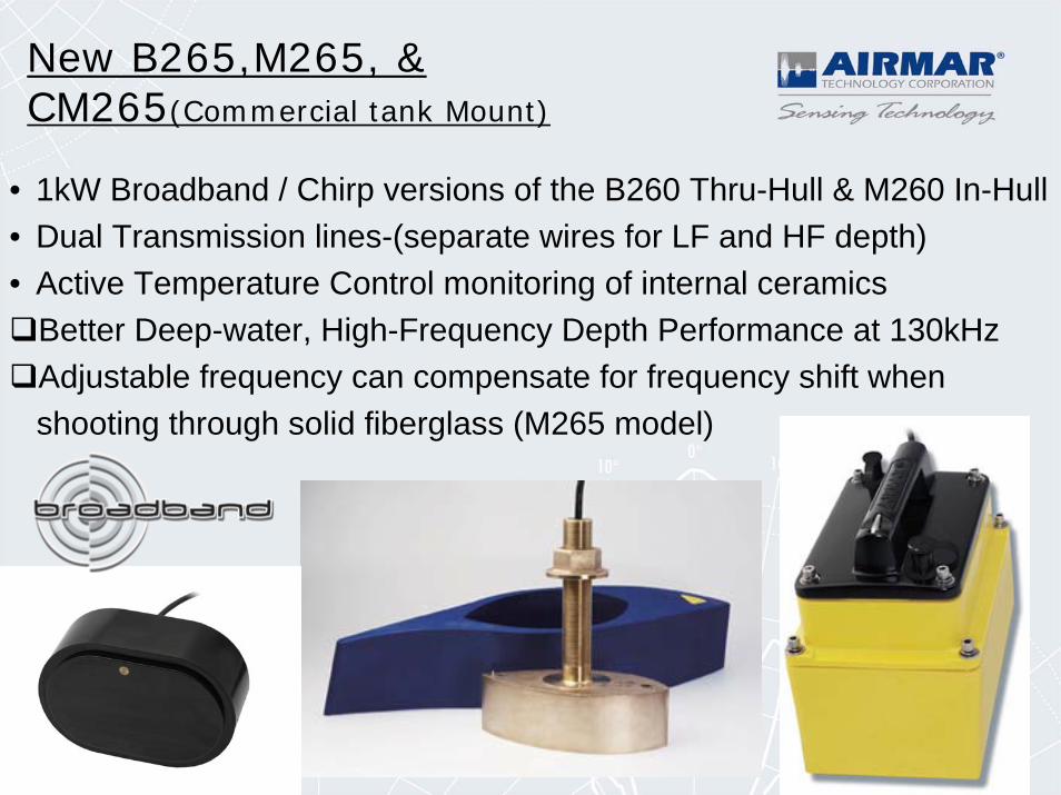
• 1kW Broadband / Chirp versions of the B260 Thru-Hull & M260 In-Hull• Dual Transmission lines-(separate wires for LF and HF depth)• Active Temperature Control monitoring of internal ceramics
Better Deep-water, High-Frequency Depth Performance at 130kHzAdjustable frequency can compensate for frequency shift when shooting through solid fiberglass (M265 model)
New B265,M265, & CM265(Commercial tank Mount)
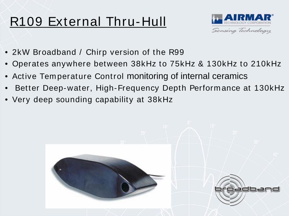
• 2kW Broadband / Chirp version of the R99• Operates anywhere between 38kHz to 75kHz & 130kHz to 210kHz
• Active Temperature Control monitoring of internal ceramics• Better Deep-water, High-Frequency Depth Performance at 130kHz• Very deep sounding capability at 38kHz
R109 External Thru-Hull
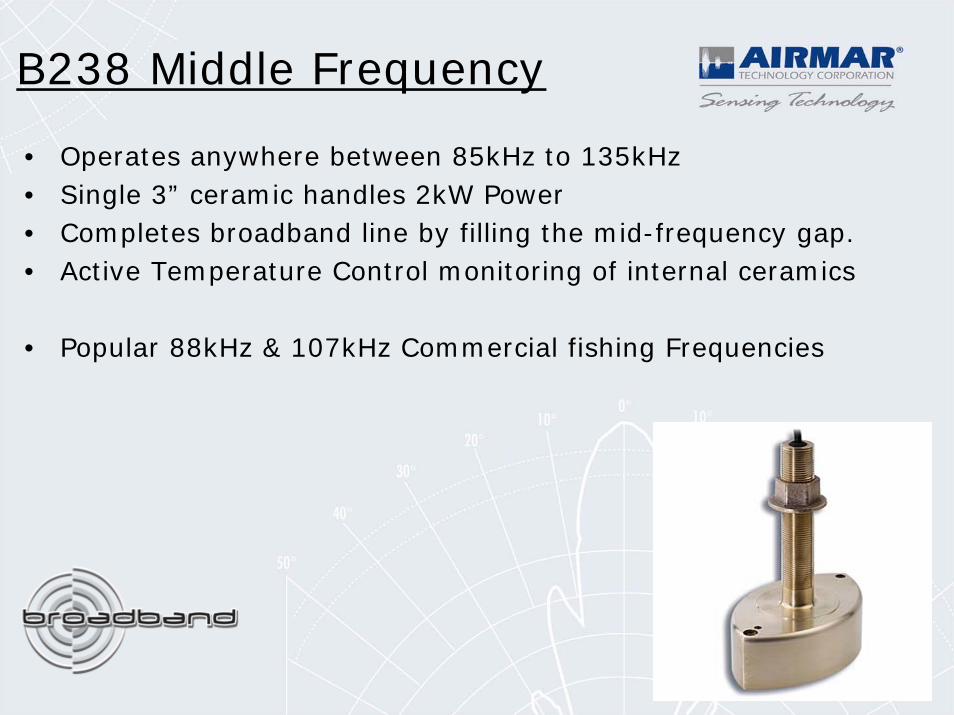
B238 Middle Frequency
• Operates anywhere between 85kHz to 135kHz• Single 3” ceramic handles 2kW Power• Completes broadband line by filling the mid-frequency gap.• Active Temperature Control monitoring of internal ceramics
• Popular 88kHz & 107kHz Commercial fishing Frequencies
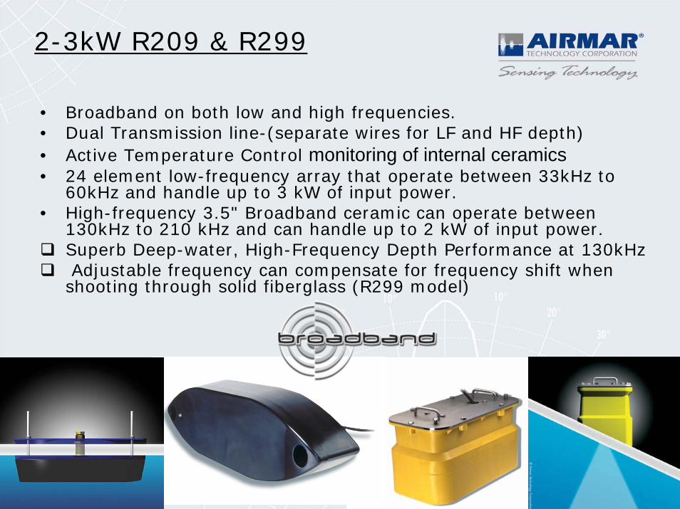
2-3kW R209 & R299
• Broadband on both low and high frequencies.• Dual Transmission line-(separate wires for LF and HF depth)• Active Temperature Control monitoring of internal ceramics• 24 element low-frequency array that operate between 33kHz to
60kHz and handle up to 3 kW of input power.• High-frequency 3.5" Broadband ceramic can operate between
130kHz to 210 kHz and can handle up to 2 kW of input power.Superb Deep-water, High-Frequency Depth Performance at 130kHzAdjustable frequency can compensate for frequency shift when shooting through solid fiberglass (R299 model)
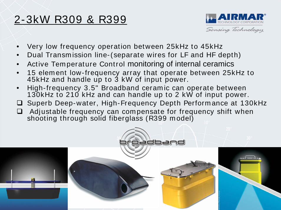
2-3kW R309 & R399
• Very low frequency operation between 25kHz to 45kHz• Dual Transmission line-(separate wires for LF and HF depth)• Active Temperature Control monitoring of internal ceramics• 15 element low-frequency array that operate between 25kHz to
45kHz and handle up to 3 kW of input power.• High-frequency 3.5" Broadband ceramic can operate between
130kHz to 210 kHz and can handle up to 2 kW of input power.Superb Deep-water, High-Frequency Depth Performance at 130kHzAdjustable frequency can compensate for frequency shift when shooting through solid fiberglass (R399 model)
Installing & Troubleshooting Transom-Mount Models
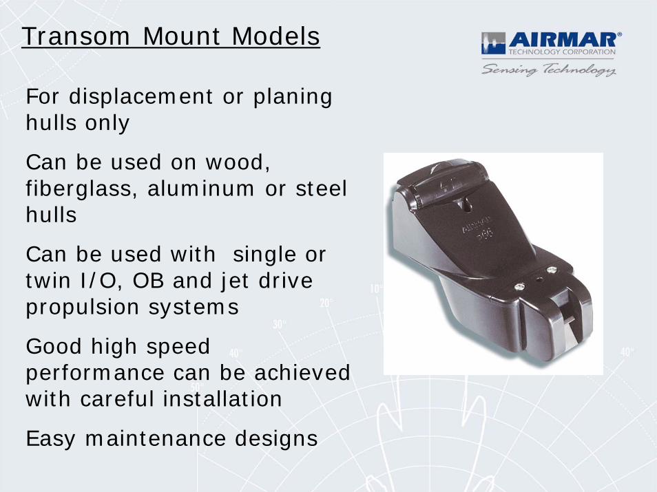
For displacement or planing hulls only
Can be used on wood, fiberglass, aluminum or steel hulls
Can be used with single or twin I/O, OB and jet drive propulsion systems
Good high speed performance can be achieved with careful installation
Easy maintenance designs
Transom Mount Models
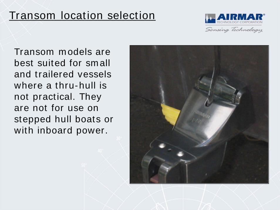
Transom location selection
Transom models are best suited for small and trailered vessels where a thru-hull is not practical. They are not for use on stepped hull boats or with inboard power.
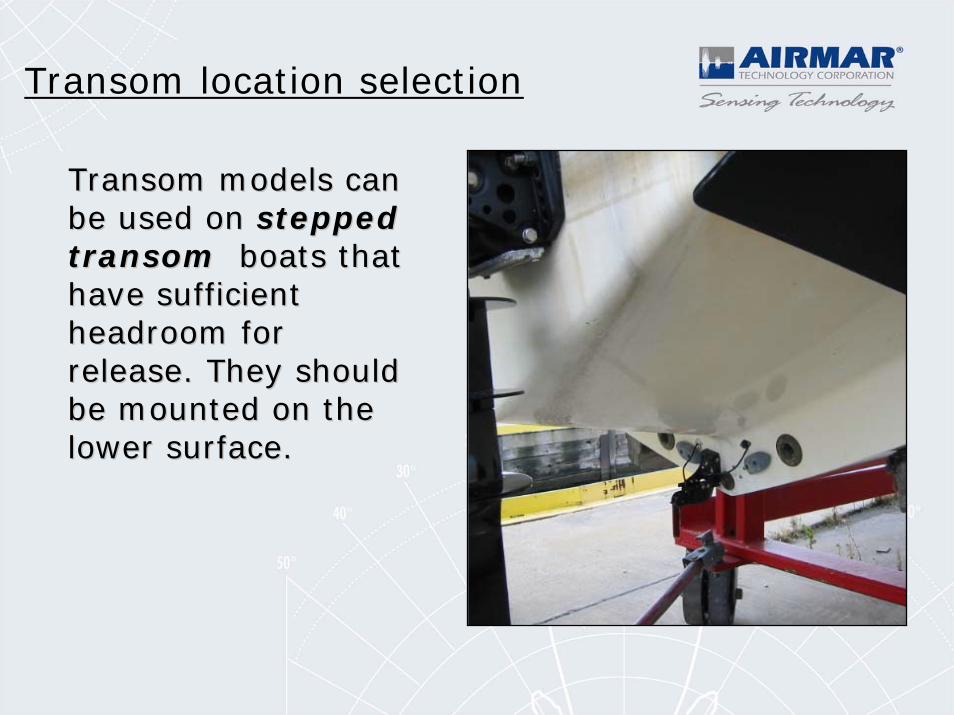
Transom location selection
Transom models can Transom models can be used on be used on steppedsteppedtransomtransom boats that boats that have sufficient have sufficient headroom for headroom for release. They should release. They should be mounted on the be mounted on the lower surface.lower surface.
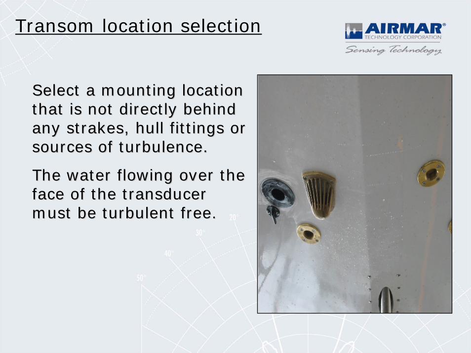
Transom location selection
Select a mounting location Select a mounting location that is not directly behind that is not directly behind any strakes, hull fittings or any strakes, hull fittings or sources of turbulence. sources of turbulence.
The water flowing over the The water flowing over the face of the transducer face of the transducer must be turbulent free.must be turbulent free.
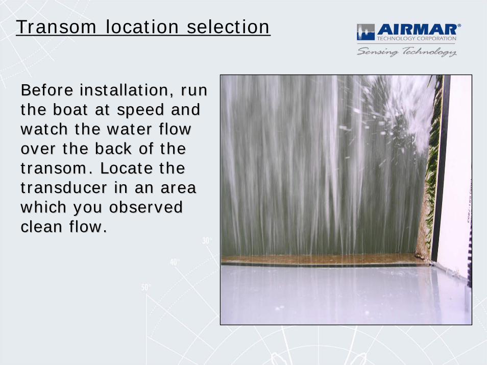
Transom location selection
Before installation, run Before installation, run the boat at speed and the boat at speed and watch the water flow watch the water flow over the back of the over the back of the transom. Locate the transom. Locate the transducer in an area transducer in an area which you observed which you observed clean flow.clean flow.
Transom location selection
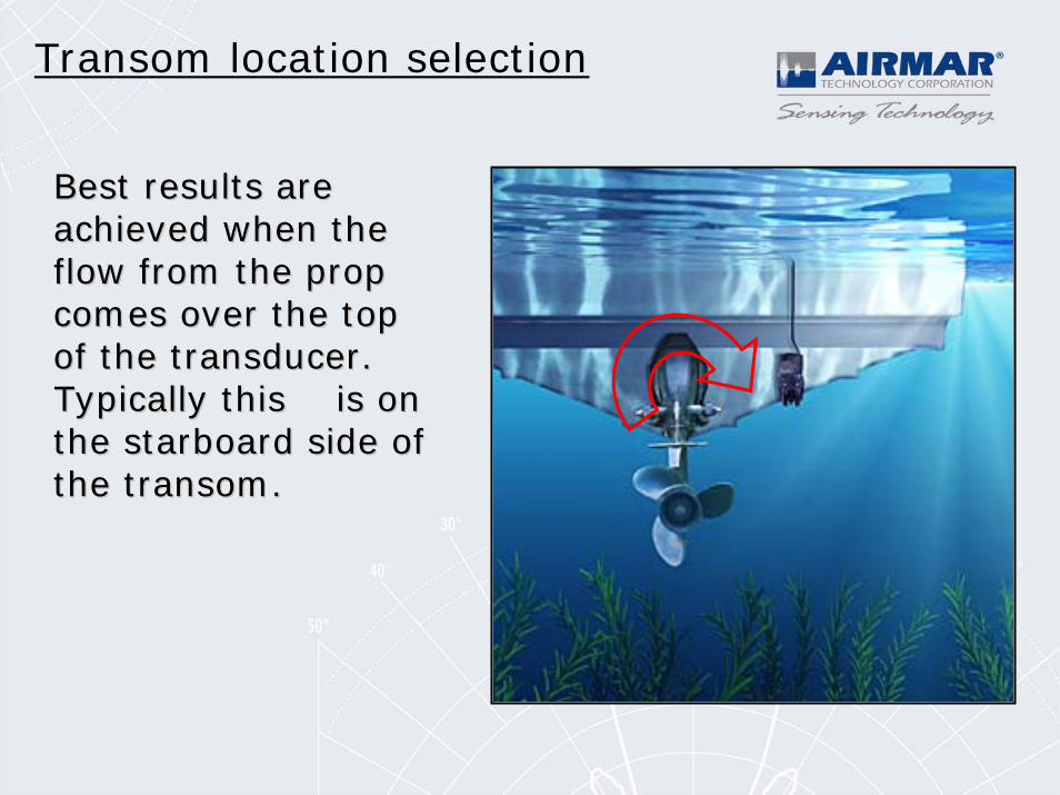
Best results are Best results are achieved when the achieved when the flow from the prop flow from the prop comes over the top comes over the top of the transducer. of the transducer. Typically this is on Typically this is on the starboard side of the starboard side of the transom. the transom.
Transom location selection
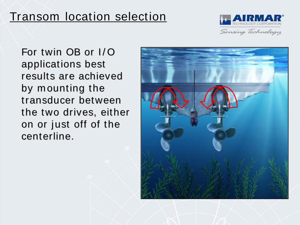
For twin OB or I/O For twin OB or I/O applications best applications best results are achieved results are achieved by mounting the by mounting the transducer between transducer between the two drives, either the two drives, either on or just off of the on or just off of the centerline.centerline.
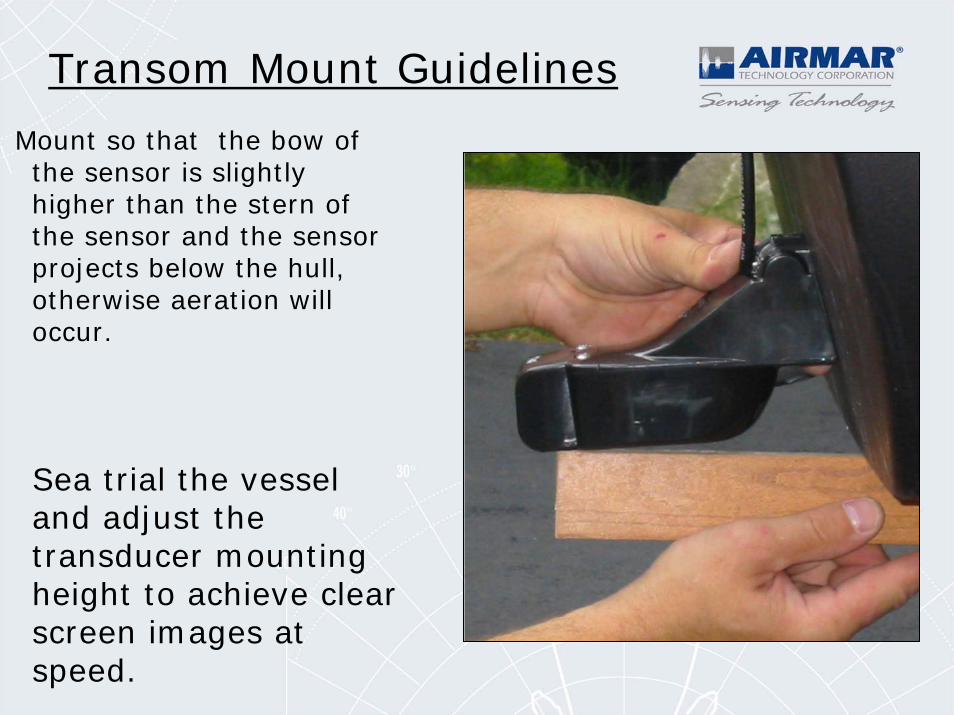
Mount so that the bow of the sensor is slightly higher than the stern of the sensor and the sensor projects below the hull, otherwise aeration will occur.
Transom Mount Guidelines
Sea trial the vessel and adjust the transducer mounting height to achieve clear screen images at speed.
If experiencing interference with a transom mounted transducer you must test drive the vessel to determine what speed the image is lost at.
Move the transducer to it’s lowest position and retest.
If screen image is improved repeat until you are satisfied with results.
If screen image gets worse, move transducer up and re-test until improvement is seen.
Transom Mount Flow Noise
• Perform a slow but constant turn to the side of the hull that the transom transducer is mounted. Gradually increase rate of turn. If screen image improves the transducer needs to be mounted lower in the water.
• If screen image is worse when turning to the same side as the transducer try turning the opposite direction. This would indicate the transducer needs to be mounted higher in the water.
Transom Mount Flow Noise