semiconductor energy laboratory co., ltd, plaintiff
TRANSCRIPT

3/3/10 1:57 AMUntitled Document
Page 1 of 26file:///Users/sethchase/Desktop/Markman/htmlfiles/2006.03.27_SEM…TOR_ENERGY_LABORATORY_CO_LTD_v._CHI_MEI_OPTOELECTRONICS_CO.html
United States District Court,N.D. California.
SEMICONDUCTOR ENERGY LABORATORY CO., LTD,Plaintiff.v.CHI MEI OPTOELECTRONICS CORP. et al,Defendants.
No. C 04-04675 MHP
March 27, 2006.
Barbara S. Steiner, Donald R. Harris, John E. Titus, Joseph F. Marinelli, Joseph Albert Saltiel, Matthew J.Thomas, Patrick L. Patras, Reginald J. Hill, Stanley A. Schlitter, Stephen M. Geissler, Terrence JosephTruax, Jenner & Block LLP, Chicago, IL, Victoria F. Maroulis, Quinn Emanuel Urquhart Oliver & HedgesL, Redwood Shores, CA, R. Tulloss Delk, Quinn Emanuel Urquhart Oliver & Hedges LLP, San Francisco,CA, for Plaintiff.
Teresa M. Corbin, Daniel X. Yan, Howrey LLP, San Francisco, CA, Benjamin Charles Deming, ChristopherAnthony Mathews, Howrey LLP, Los Angeles, CA, Ryan Edward Lindsey, Yuri Mikulka, Howrey LLP,Irvine, CA, Robert Unikel, Howrey LLP, Chicago, IL, for Defendants.
MEMORANDUM & ORDER
Re: Claim Construction
MARILYN HALL PATEL, District Judge.
Plaintiff Semiconductor Energy Laboratory Co. brought this patent infringement action against defendantsChi Mei Optoelectronics Corp. et al., alleging infringement of four United States patents related generally tothe design and manufacture of liquid crystal display ("LCD") devices. Now before the court are the parties'claim construction briefs, filed pursuant to Patent Local Rule 4-5. Having considered the parties' argumentsand submissions, and for the reasons set forth below, the court construes the disputed terms as follows.
BACKGROUND
Plaintiff is the assignee of the four patents at issue in this lawsuit: U.S. Patent Nos. 6,756,258 (the "'258patent"), 6,404,480 (the "'480 patent"), 5,995,189 (the "'189 patent") and 4,691,995 (the "'995 patent"). Eachof the four patents relates to the design and manufacture of LCD panels-the ubiquitous display devices usedin electronic equipment ranging from digital clocks to flat screen televisions.
I. Overview of LCD Devices
3/3/10 1:57 AMUntitled Document
Page 2 of 26file:///Users/sethchase/Desktop/Markman/htmlfiles/2006.03.27_SEM…TOR_ENERGY_LABORATORY_CO_LTD_v._CHI_MEI_OPTOELECTRONICS_CO.html
An LCD consists of liquid crystal material sandwiched between two transparent sheets, referred tothroughout each of the four patents as "substrates." See, e.g., '480 patent at 1:24-35. In addition to the liquidcrystal material, a number of solid "spacers" may be placed in the region between the substrates in order tomaintain a uniformly wide gap. See id. at 2:20-22. A seal around the edges of the substrates holds the liquidcrystal in. See '189 patent at 2:12-18.
Both substrates are patterned with identically shaped grids of electrodes-areas of electrically conductivematerial-arranged in rows and columns like the squares of a chess board. Each electrode in the gridcorresponds to a single picture element, or pixel. FN1 During assembly, the two substrates are positionedsuch that their grids of electrodes face each other in precise alignment. As a result, after assembly, eachpixel consists of a pair of opposed electrodes with liquid crystal material between them. The grids ofelectrodes are connected to control circuitry such that the opposing electrodes at each point can beindependently set to a desired voltage differential. When a voltage differential is applied to a particularpixel, the molecules of liquid crystal between the two electrodes become aligned in such a way as to permitor block the passage of light through the display, thus turning the pixel on or off. ' 480 patent at 1:36-47.
FN1. In the case of color displays, a pixel may actually consist of multiple electrodes, each of whichcontrols transmission of a particular color of light-red, green or blue.
In sophisticated LCDs, such as those used in computer monitors and televisions, pixels are switched on andoff through the use of thin-film transistors (sometimes referred to as "TFTs") which are created on thesurface of one of the two substrates, hereinafter referred to as the "TFT substrate." ' 189 patent at 1:53-62.At least one transistor is used to control each pixel. The electrodes on the opposite substrate (the "opposingsubstrate") are not switched, but are held at constant voltage. '480 patent at 1:36-47.
The thin-film transistors used to accomplish the switching, like other transistors, typically consist of threecontiguous semiconductor "regions." The semiconductor most commonly used in thin-film transistors issilicon. Each of the three semiconductor regions is connected to a metallic terminal. Two of the terminals-referred to as the "collector" and "emitter" or the "source" and "drain"-are the entry and exit point forcurrent flowing through the transistor. The voltage applied to the third terminal-the "base" or "gate"-regulates the current flowing through the transistor much as a valve regulates the flow of water. Whencurrent is flowing through a transistor, it enters at the "collector" or "source," proceeds through the "base" or"gate" region, and exits through the "emitter" or "drain."
The silicon used in the three regions of a transistor can be in one of several forms, each of which has adifferent crystalline structure, or configuration of individual silicon atoms. The element carbon provides amore familiar example of how a single chemical element can be arranged in different crystalline structures.One form of carbon, graphite, consists of carbon atoms which lack a regular crystalline structure. Incontrast, a diamond is made of carbon arranged into a regular crystal lattice. Likewise, "amorphous" silicon(analogous to graphite) consists of silicon atoms arranged without a crystalline structure. Amorphous siliconis a relatively poor conductor, and not well suited to use in high-performance integrated circuits. In contrast,"crystalline" silicon (analogous to a diamond), whether it is "polycrystalline" or "microcrystalline," is asubstantially better conductor. See generally ' 258 patent at 1:23-33.
The four patents at issue in this lawsuit relate to various problems in the design and construction of LCDs,including LCDs that make use of silicon thin-film transistors.
3/3/10 1:57 AMUntitled Document
Page 3 of 26file:///Users/sethchase/Desktop/Markman/htmlfiles/2006.03.27_SEM…TOR_ENERGY_LABORATORY_CO_LTD_v._CHI_MEI_OPTOELECTRONICS_CO.html
II. The '258 Patent
Transistors in integrated circuits, including the thin-film transistors used in LCDs, are fabricated bysuccessively depositing layers of various conductive and insulating materials-such as metallic materials andsilicon-and then selectively removing material from those layers to form a desired pattern. Thesemiconductor regions of thin-film transistors used in LCDs are often fabricated from a layer of amorphoussilicon, which can be manipulated at temperatures that are not so high as to harm the underlying material. Inorder to achieve better conductivity (which is desirable for high-performance LCDs) the amorphous siliconmust later be converted to a crystalline form of silicon. One way of performing this conversion is byexposing the amorphous silicon to radiation from a laser. See id.
The '258 patent teaches a method of constructing thin-film transistors such that their silicon regions can beirradiated by a laser after the structures of their transistors are completely formed, rather than at some pointduring the middle of the fabrication process. Id. at 5:1-5. The principal benefit of allowing irradiation at theend of the fabrication process is that the electrical characteristics of the transistors (which depend on theconductivity of the silicon regions) can be monitored during the irradiation using equipment that isconnected to the transistor's terminals. Thus, the conductivity can be precisely calibrated. Id . at 5:6-40.
III. The '480 Patent
As already discussed, both substrates in an LCD are patterned with electrodes. The electrodes on the TFTsubstrate are switched on and off through the use of transistors, while the electrodes on the opposingsubstrate are held at a constant electric potential through connection to a constant voltage source, or"clamp." In some cases, the voltage source is located on the TFT substrate. In order to connect theelectrodes on the opposing substrate to the voltage source, a conductive spacer must bridge the gap betweenthe substrates. '480 patent at 1:24-47.
The '480 patent provides a way of reliably creating an electrical connection from the TFT substrate to theopposing substrate while maintaining a uniform gap between the substrates. One obstacle to achieving auniform gap in the prior art is variation in thickness of the insulating-or "dielectric"-layer deposited justbeneath the electrodes on the TFT substrate. In prior art displays, the metal contact for the electricalconnection to the counter substrate was located on a layer below the level of the dielectric. See id. Fig. 17.Thus, the conductive spacer had to be of a size roughly equal to the thickness of the dielectric layer plus thewidth of the gap between the substrates in order to make electrical contact with both substrates. Because itis difficult to control the thickness of the dielectric layer from panel to panel, and even within a singlepanel, it was difficult to create spacers of the correct size. The improvement of the '480 patent is to locatethe metal contact for the electrical connection on top of the dielectric layer, eliminating the relationshipbetween the thickness of the dielectric and the size of the conductive spacers. Id. at 3:21-48.
IV. The '189 Patent
In order to contain the liquid crystal in the space between the substrates, the substrates must be bondedtogether and the edges of the LCD must be sealed. '189 patent at 2:12-18. In order to connect the electrodes,which are located inside the seal, to the outside of the LCD (for example, to receive power and the videosignal to be displayed), wires must extend from the inside to the outside of the display, passing through theregion of the seal. In some LCD panels, however, the wires do not cross the seal on all sides. The substratein the areas where the wires cross the seal is thicker than the substrate where the wires do not cross; the

3/3/10 1:57 AMUntitled Document
Page 4 of 26file:///Users/sethchase/Desktop/Markman/htmlfiles/2006.03.27_SEM…TOR_ENERGY_LABORATORY_CO_LTD_v._CHI_MEI_OPTOELECTRONICS_CO.html
resulting asymmetry can cause a lopsided or imperfect fit when the two substrates are brought together andthe seal is interposed between them. Id. at 2:35-52.
The invention of the '189 patent addresses the asymmetry by adding a "substrate interval correction means"to the sides of the panel where no wiring crosses the seal. In the preferred embodiments of the '189 patent,the interval correction means is formed of the same material and at the same time in the fabrication processas the wires that cross the seal. The correction means, however, is not electrically connected to any circuitry.
V. The '995 Patent
In assembling an LCD, the gap between the substrates must be filled with liquid crystal material. One wayof filling the LCD, as taught in prior art to the '995 patent, is to bond the two substrates together, leaving anopening in the seal at the edge of the LCD. A vacuum is then created, removing the air from inside theLCD. Liquid crystal is then sucked in through the opening-much like a turkey baster or eyedropper-byexposing the opening to a pool of liquid crystal material and slowly increasing the surrounding pressure.'995 patent at 1:29-44.
The '995 patent teaches an alternate method of filling the gap with liquid crystal. Before the two substratesare bonded together, liquid crystal material is deposited on one of the substrates. The two substrates are thenpressed together and heated; under heat and pressure, the liquid crystal spreads to fill the gap.
LEGAL STANDARD
Under Markman v. Westview Instruments, Inc., 517 U.S. 370, 389-90, 116 S.Ct. 1384, 134 L.Ed.2d 577(1996), the court construes the scope and meaning of disputed patent claims as a matter of law. The firststep of this analysis requires the court to consider the words of the claims. Teleflex, Inc. v. Ficosca N. Am.,299 F.3d 1313, 1324 (Fed.Cir.2002). According to the Federal Circuit, the court must "indulge a 'heavypresumption' that a claim term carries its ordinary and customary meaning." CCS Fitness, Inc. v. BrunswickCorp., 288 F.3d 1359, 1366 (Fed.Cir.2002). To determine the ordinary meaning of a disputed term, the courtmay review a variety of sources, including the claims themselves, other intrinsic evidence including thewritten description and prosecution history, and dictionaries and treatises. Teleflex, 299 F.3d at 1325. Thecourt must conduct this inquiry not from the perspective of a lay observer, but rather "from the standpointof a person of ordinary skill in the relevant art." Id. (citing Zelinski v. Brunswick Corp., 185 F.3d 1311,1316 (Fed.Cir.1999)).
Among the sources of intrinsic evidence, the specification is "the single best guide to the meaning of adisputed term." Vitronics Corp. v. Conceptronic, Inc., 90 F.3d 1576, 1582 (Fed.Cir.1996). By expresslydefining terms in the specification, an inventor may "choose[ ] to be his or her own lexicographer," therebylimiting the meaning of the disputed term to the definition provided in the specification. Johnson WorldwideAssocs., Inc. v. Zebco Corp., 175 F.3d 985, 990 (Fed.Cir.1999). In addition,"[e]ven when guidance is notprovided in explicit definitional format, "the specification may define claim terms 'by implication' such thatthe meaning may be 'found in or ascertained by a reading of the patent documents.' " Irdeto Access, Inc. v.Echostar Satellite Corp., 383 F.3d 1295, 1300 (Fed.Cir.2004) (quoting Bell Atl. Network Servs., Inc. v.Covad Commc'ns Group, Inc., 262 F.3d 1258, 1268 (Fed.Cir.2001)). "The specification may also assist inresolving ambiguity where the ordinary and accustomed meaning of the words used in the claims lacksufficient clarity to permit the scope of the claim to be ascertained from the words alone." Teleflex, 299F.3d at 1325. At the same time, the Federal Circuit has cautioned that the written description "should nevertrump the clear meaning of the claim terms." Comark Commc's, Inc. v. Harris Corp., 156 F.3d 1182, 1187
3/3/10 1:57 AMUntitled Document
Page 5 of 26file:///Users/sethchase/Desktop/Markman/htmlfiles/2006.03.27_SEM…TOR_ENERGY_LABORATORY_CO_LTD_v._CHI_MEI_OPTOELECTRONICS_CO.html
(Fed.Cir.1998) (citations omitted); see also Tate Access Floors, Inc. v. Maxess Techs., Inc., 222 F.3d 958,966 (Fed.Cir.2000) ("Although claims must be read in light of the specification of which they are part, ... itis improper to read limitations from the written description into a claim ....").
Likewise, the prosecution history may demonstrate that the patentee intended to deviate from a term'sordinary and accustomed meaning. Teleflex, 299 F.3d at 1326. "Arguments and amendments made duringthe prosecution of a patent application and other aspects of the prosecution history, as well as thespecification and other claims, must be examined to determine the meaning of terms in the claims."Southwall Techs., Inc. v. Cardinal IG Co., 54 F.3d 1570, 1576 (Fed.Cir.), cert. denied, 516 U.S. 987, 116S.Ct. 515, 133 L.Ed.2d 424 (1995). "In particular, 'the prosecution history (or file wrapper) limits theinterpretation of claims so as to exclude any interpretation that may have been disclaimed or disavowedduring prosecution in order to obtain claim allowance.' " Teleflex, 299 F.3d at 1326 (quoting Standard OilCo. v. American Cyanamid Co., 774 F.2d 448, 452 (Fed.Cir.1985)).
Dictionary definitions and other objective reference materials available at the time that the patent was issuedmay also provide evidence of the ordinary meaning of a claim. Phillips v. AWH Corp. ., 415 F.3d 1303,1322 (Fed.Cir.2005) (en banc); Texas Digital Sys., Inc. v. Telegenix, Inc., 308 F.3d 1193, 1202(Fed.Cir.2002). A dictionary "has the value of being an unbiased source, accessible to the public in advanceof litigation." Phillips, 415 F.3d at 1322 (internal quotation omitted). Thus, district courts "are free toconsult such resources at any time in order to better understand the underlying technology and may also relyon dictionary definitions when construing claim terms, so long as the dictionary definition does notcontradict any definition found in or ascertained by a reading of the patent documents." Vitronics, 90 F.3d at1584 n. 6. A court should be cautious, however, not to place too much reliance on dictionaries, as theresulting construction may be too broad. Phillips, 415 F.3d at 1321.
Federal Circuit decisions take a less favorable view of other forms of extrinsic evidence, such as experttestimony and prior art not cited in the specification or the prosecution history, noting that "claims shouldpreferably be interpreted without recourse to extrinsic evidence, other than perhaps dictionaries or referencebooks, and that expert testimony should be received only for the purpose of educating the judge." EMIGroup N. Am., Inc. v. Intel Corp., 157 F.3d 887, 892 (Fed.Cir.1998), cert. denied, 526 U.S. 1112, 119 S.Ct.1756, 143 L.Ed.2d 788 (1999). Although "extrinsic evidence in general, and expert testimony in particular,may be used ... to help the court come to a proper understanding of the claims[,] it may not be used to varyor contradict the claim language .... Indeed, where the patent documents are unambiguous, expert testimonyregarding the meaning of a claim is entitled to no weight." Vitronics, 90 F.3d at 1584.
The Federal Circuit recently revisited the basic approach to claim construction in Phillips. Although Phillipsconsists largely of an affirmation of ten years of claim construction jurisprudence, it provides at least twopieces of additional guidance. First, the Federal Circuit rejected a line of cases suggesting that claiminterpretation must begin with a dictionary definition of the disputed terms. Phillips, 415 F.3d at 1320-21.Second, the Federal Circuit emphasized that claim terms must be interpreted in light of their context,especially the language used in other claims and the specification. See id. at 1321. Taken as a whole,Phillips appears to signal a small retreat from formalism and bright-line rules in claim construction. As aresult, the court will focus primarily on the intrinsic record before it. Cases cited by the parties in support offixed "rules" of claim construction will accordingly be given somewhat less weight.
The parties disagree as to whether the court must provide a construction for each disputed term, or whetherthe court can find the claim language itself to be sufficiently clear. Plaintiff has offered no proposed

3/3/10 1:57 AMUntitled Document
Page 6 of 26file:///Users/sethchase/Desktop/Markman/htmlfiles/2006.03.27_SEM…TOR_ENERGY_LABORATORY_CO_LTD_v._CHI_MEI_OPTOELECTRONICS_CO.html
construction for several of the terms, arguing that they are unambiguous. Defendants argue thatunambiguousness is a "myth," and that the court is required to provide clarification as to the meaning ofeach term. Defendants also argue that by claiming certain terms to be unambiguous, plaintiff has waived anyright to argue in favor of alternate constructions.
Defendants' first argument is misguided because the role of a court in claim construction, viewed broadly, isto provide language which as accurately as possible captures the nature and scope of the invention. Claimsthemselves consist of language, which may already be sufficiently clear. Adding to or rephrasing the claimlanguage often introduces more problems than it solves. Regardless of the level of care exercised by thecourt, the parties will continue to "construe the construction" through the dispositive motions and trial whichoften follow Markman hearings. Other judges, including Judge Breyer in this district, have recognized thatsome claim terms will not benefit from further clarification. See ICU Med., Inc. v.B. Braun Med., Inc., 344F.Supp.2d 663, 673 (N.D.Cal.2004) (Breyer, J.) (declining to provide further elaboration on the claim terms"substantially flat" and "substantially flush").
In addition, a court provides clarification as to the meaning of disputed claim language even if it does notcraft an alternate formulation. With respect to many of the claim phrases at issue here, one of the partiesseeks to limit the scope of the disputed phrase by adding qualifiers or restrictions. If the court rejects thosequalifiers and adopts the claim language itself, the parties are of course bound by that rejection and may notlater argue that the claim language implicitly contains the rejected restrictions. The parties are bound by thecourt's reasoning as well as the resulting construction itself.
Defendants' second argument-that plaintiff has "waived" its right to offer alternate constructions-has nobearing on the court's ability to determine the proper construction as a matter of law. A court is free toaccept either party's proposed construction, or to reject both if both are flawed. Exxon Chem. Patents v.Lubrizol Corp., 64 F.3d 1553, 1555 (Fed.Cir.1995) ("the trial judge has an independent obligation todetermine the meaning of the claims, notwithstanding the views asserted by the adversary parties.").Plaintiff's argument that no construction is necessary is really just an assertion that the claim language isalready adequate. If the court finds plaintiff to be in error, the court is not bound to accept defendants'proposal as a result.
DISCUSSION
The following chart summarizes the court's construction of the disputed terms. The full analysis supportingeach construction is below.
PatentTerm Construction'258 wherein a portion of the patterned second
semiconductor film is exposed" part of the second semiconductor film is madesubject to etching"
'258 etching the exposed portion of the secondsemiconductor film
"removing the entire exposed portion of the secondsemiconductor film"
'258 channel forming region "the region of a semiconductor device in which thechannel may form"
'258wherein said conductive layer is overetched / overetching the conductive layerNo construction isnecessary.

3/3/10 1:57 AMUntitled Document
Page 7 of 26file:///Users/sethchase/Desktop/Markman/htmlfiles/2006.03.27_SEM…TOR_ENERGY_LABORATORY_CO_LTD_v._CHI_MEI_OPTOELECTRONICS_CO.html
'480 conductive spacers "conductive objects that span the gap between substrates"'189 an element substrate having / an
element substrate ... having"the substrate having a matrix circuit and a peripheral drivecircuit driving said matrix circuit"
'189 substrate interval correction means "a structure, located in the areas of the sealing forming regionwhere no wires cross, which compensates for the asymmetry inthe wires crossing the sealing region"
'189 a plurality of pixel electrodesdisposed on cross points
"pixel electrodes atop the intersections of the signal andscanning lines"
'995 first substrate No construction is necessary.'995 a step of placing an amount of liquid
crystal on plural locations on the firstsubstrate
"depositing an amount of liquid crystal material in multiplelocations on a substrate"
'995 preparing first and second substratesprovided with active elements
" preparing the first and second substrates such that at least onesubstrate has active elements"
'995 sealing structure "a structure, made after the second substrate is laid on the first,which may help to contain the liquid crystal material within thecavity between the two substrates or to keep impurities out"
'995 the periphery No construction is necessary.'995 the liquid crystal is filled ... so as
not to overflow / the liquid crystalis extended ... without overflowing
No construction is necessary.
I. The '258 Patent
As described above, the '258 patent describes a way of creating thin film transistors such that the amorphoussilicon in the transistors can be irradiated by a laser after the transistors' structures are completely formed.Claim 3 of the '258 patent contains each of the four disputed claim elements:
3. A method of manufacturing a semiconductor device comprising the steps of:
forming a gate electrode on an insulating surface;
forming a gate insulating film comprising silicon nitride on said gate electrode;
forming a first semiconductor film comprising amorphous silicon over said gate electrode with said gateinsulating film interposed therebetween;
forming a second semiconductor film on said first semiconductor film, said second semiconductor filmdoped with an N-type dopant;
patterning said first and second semiconductor films;
forming a conductive layer on the patterned second semiconductor film;
patterning the conductive layer to form source and drain electrodes by using a mask wherein a portion ofthe patterned second semiconductor film is exposed between said source and drain electrodes;
3/3/10 1:57 AMUntitled Document
Page 8 of 26file:///Users/sethchase/Desktop/Markman/htmlfiles/2006.03.27_SEM…TOR_ENERGY_LABORATORY_CO_LTD_v._CHI_MEI_OPTOELECTRONICS_CO.html
etching the exposed portion of the second semiconductor film to form source and drain regions whereina channel forming region is formed in said first semiconductor film between said source and drain regions,
wherein said conductive layer is overetched to form a stepped portion from an upper surface at the sourceand drain electrodes to a surface at the first semiconductor film.
'258 patent at 12:33-59.
A. "wherein a portion of the patterned second semiconductor film is exposed" / "etchin the exposedportion of the second semiconductor film" / "wherein said conductive layer is overetched"
The parties' arguments with respect to three of the four disputed phrases are intertwined, and depend ondiffering interpretations of the breadth of the last three elements taken as a whole. The parties are inagreement that the final three elements encompass at least two distinct steps. Prior to the steps claimed in thefinal three elements, a conductive layer-generally metallic-covers the entire substrate, as shown in Figure3(E) of the '258 patent. In the first undisputed step, a template or "mask" is applied to the top of theconductive layer and an etchant is applied to remove parts of the conductive layer that are not protected bythe mask, thus "patterning the conductive layer" (the "patterning" step). In the second undisputed step, atleast part of the semiconductor film previously covered by the conductive layer, and now uncovered as aresult of the "patterning" step, is exposed to an etchant and removed (the "etching" step). The partiesdisagree as to whether the third claim element, beginning with "wherein said conductive layer isoveretched," corresponds to an additional, subsequent step of further etching the conductive layer, orwhether the "overetch[ing]" may take place as part of the patterning step.
Understanding the parties' dispute requires a brief exploration of how etching takes place. Both partiespresented extensive technical tutorials during the Markman hearing, and the following background facts arenot in dispute. An etchant is a substance which can be used to remove material from the surface of asemiconductor device during fabrication. Etchants come in one of two varieties. So-called "dry" etchants areabrasive substances that are used to bombard the target material and remove the material anisotropically, inthe direction of the bombardment-a process similar to sandblasting. When a dry etchant is used inconjunction with a mask, only those areas not covered by the mask are etched. "Wet" etchants, on the otherhand, are solvents that remove the target materially isotropically, or at the same rate in all directions. Whena wet etchant is used in conjunction with a mask, in addition to removing material in the areas not coveredby the mask, the etchant "undercuts" the mask, removing material under the edges of the mask. Seegenerally Harris Dec., Exh. 3. The longer the wet etchant is applied, the more undercutting takes place.
The parties do not disagree as to the behavior of etchants generally, or as to the effect of using differenttypes of etchants to perform the claimed steps. Under defendants' proposed interpretation of the threedisputed elements, however, no undercutting takes place during the "patterning" step. Defendants' proposedconstruction thus limits the claimed invention to the use of anisotropic-generally, dry-etchants in both thepatterning and etching steps. In such a case, the portion of the underlying semiconductor film "exposed"during the patterning step is exactly as wide as the area of the conductive layer removed through patterning,which in turn is exactly as wide as the opening in the mask. During the "etching" step which follows, theentire portion of the semiconductor film not covered by the conductive layer and the mask is removed.Finally, defendants argue that the structure must be "overetched" as a separate final step, after the secondsemiconductor layer is etched.
3/3/10 1:57 AMUntitled Document
Page 9 of 26file:///Users/sethchase/Desktop/Markman/htmlfiles/2006.03.27_SEM…TOR_ENERGY_LABORATORY_CO_LTD_v._CHI_MEI_OPTOELECTRONICS_CO.html
In line with their interpretation of the final three elements, defendants argue that the phrase "wherein aportion of the patterned second semiconductor film is exposed" should be construed to mean "part of thesecond semiconductor film is not shielded or protected by the conductive layer." Defendants further arguethat the phrase "etching the exposed portion of the second semiconductor film" should be construed to mean"removing the entire portion of the part of the second semiconductor film that is not shielded or protected bythe conductive layer." Finally, defendants argue that the phrase "wherein said conductive layer isoveretched" means "an additional step of removing portions of the conductive layer not previouslyremoved." Taken in combination, defendants' proposed claim construction limits the claims to the specificsequence of steps displayed in Figures 3(E)-3(H): a mask P3 is applied; the conductive layer 7 and thesecond semiconductor layer 6 are anisotropically etched where they are not covered by the mask; theconductive layer 7 is further etched, exposing additional portions of the second semiconductor layer. In theresulting structure, the gap in the conductive layer is wider than the gap in the second semiconductor layer.
Plaintiff agrees that the series of steps proposed by defendants is within the scope of the final three claimelements, but argues that the claim further encompasses an alternate method of achieving the same result.According to plaintiff, the "patterning" step may result in undercutting of the conductive layer if a wetetchant is used, such that the resulting width of the gap in the conductive layer is greater than the width ofthe gap in the mask. During the subsequent etching step, if a dry etchant is used, only the portion of thesemiconductor film unprotected by the mask will be etched. Under plaintiff's interpretation of the patterningand etching steps, the portion of the semiconductor film "exposed" to the dry etchant may thus be smallerthan the portion of the semiconductor film no longer covered by the conductive layer. The result will be thesame-the gap in the conductive layer will be wider than the gap in the semiconductor film-but no separateoveretching step is required. Plaintiff does not propose an alternate construction, but instead argues that theclaim language is unambiguous and does not require further explanation.
Having framed the overall dispute, the court now turns to each of the disputed claim phrases.
1. "wherein a portion of the patterned second semiconductor film is exposed"
The patent provides relatively little guidance on the meaning of "exposed," which is used in the contestedsense only in the claims.
Based on the available intrinsic evidence, however, the court finds that "exposed" means "made subject toetching." The claim language supports the preceding construction: the full clause of claim 3 that contains thedisputed language requires "patterning the conductive layer to form source and drain electrodes by using amask wherein a portion of the patterned second semiconductor film is exposed between said source anddrain electrodes." ' 258 patent at 12:48-51. The following claim element requires "etching the exposedportion of the second semiconductor film." Id. at 12:52-53. The exposed portion is etched.
Moreover, as the parties do not dispute, the portion of the semiconductor film that will be etched depends onthe type of etchant used. If a dry etchant is used to remove the semiconductor film, only the area notcovered by the mask will be removed, regardless of whether the conductive layer was previously overetchedusing a wet etchant. If a wet etchant is used to remove the semiconductor film, part of the semiconductorfilm lying underneath the mask will also be removed, regardless of whether the conductive layer waspreviously etched using a dry etchant. As discussed in more detail below, the claims encompass the use ofboth wet and dry etchants in performing the patterning step, and also encompass the use of a dry etchant inperforming the etching step. Defendants' proposed construction is therefore too narrow.
3/3/10 1:57 AMUntitled Document
Page 10 of 26file:///Users/sethchase/Desktop/Markman/htmlfiles/2006.03.27_SE…TOR_ENERGY_LABORATORY_CO_LTD_v._CHI_MEI_OPTOELECTRONICS_CO.html
The specification, to the extent it discusses the patterning step, also supports the court's construction: "[theconductive] layer was patterned, using a third photomask P3. At this time, the ... amorphous silicon layerwas patterned by dry etching without peeling off resist 8." Id. at 7:12. The "resist," which the parties do notdispute is synonymous with the "mask," is present for both the patterning of the conductive material and thesubsequent etching of the amorphous silicon. With the mask still present, as discussed above, the materialthat will be removed (the "exposed" material) in both the patterning and etching steps depends on the type ofetchant used.
In sum, the court construes the first disputed phrase to mean "part of the second semiconductor film is madesubject to etching."
2. "etching the exposed portion of the second semiconductor film"
In light of the preceding construction of "exposed," by definition the entire "exposed" portion is etchedaway. The court therefore construes the second disputed phrase to mean "removing the entire exposedportion of the second semiconductor film." Indeed, both parties agree that the entire "exposed" portion isetched away. Pl.'s Opening Brief at 8 ("The mask ... determines which areas are exposed to the etchant, andhence are etched away."); Defs.' Response Brief at 9 ("Since the exposed portion of the secondsemiconductor film is the portion not protected by the conductive layer, etching that portion thus involvesits complete removal.").
3. "wherein said conductive layer is overetched"
The court has already concluded that nothing in the language of the patterning and etching steps limits theclaimed invention to the embodiment shown in Figure 3. The question remains, however, whether the finalclaim element requires that overetching be performed as a separate step.
The '258 patent includes eight independent claims, which are identical aside from variations in the final"etching" and "overetching" elements. In order to determine the meaning of "overetched" in claim 3, it isuseful to examine the overall claiming scheme in the patent.
The first three independent claims are the broadest; the final elements of each claim focus on the geometrythat results from the claimed process, with little or no indication of how that result is achieved. See '258patent at 12:3-5 (claim 1) ("wherein an upper surface of the source and drain regions is partially exposedfrom said source and drain electrodes"); id. at 12:29-32 ("wherein a distance between the source and drainregions at an upper surface thereof is shorter than a distance between the source and drain electrodes at alower surface thereof"). The final element of claim 3 also focuses on the resulting geometry, and furtherstates that the geometry is achieved through the conductive layer being "overetched": "wherein saidconductive layer is overetched to form a stepped portion from an upper surface at the source and drainelectrodes to a surface at the first semiconductor film." Id. at 12:56-59.
Claims 4 and 5 are identical to claims 1 and 2, with the substitution of "overetching the conductive layer bywet etching so that" for "wherein." See, e.g., id. at 13:16-18 ("over etching [sic] the conductive layer by wetetching so that an upper surface of the source and drain regions is partially exposed from said source anddrain electrodes"). Claim 6 is identical to claim 3 with the addition of "by wet etching" after "wherein saidconductive layer is over etched [sic]." Id. at 14:3-4.

3/3/10 1:57 AMUntitled Document
Page 11 of 26file:///Users/sethchase/Desktop/Markman/htmlfiles/2006.03.27_SE…TOR_ENERGY_LABORATORY_CO_LTD_v._CHI_MEI_OPTOELECTRONICS_CO.html
Finally, claims 7 and 8 add two additional limitations. First, they indicate that the etching of the secondsemiconductor layer is achieved through "dry etching." E.g., id. at 14:26-29. Second, they indicate that thestep of overetching through wet etching takes place after the step of dry etching the semiconductor. Id. at14:30-31; id. at 14:55-58.
The systematic variation of claim language suggests that "overetched," as used in claim 3, is not confined toa particular type of etching (which is added in claim 6) or a particular timing for etching (which is added inclaims 7 and 8). Claim 3 requires only that the conductive layer be overetched. Both parties agree that oneof ordinary skill in the art would understand that overetching can be performed either as a separate step,involving the application of additional etchant, or by extending the original etching such that the etchantundercuts the mask. The language of claim 3 encompasses both meanings.
The use of the word "wherein," which precedes the final element of claim 3, further supports the conclusionthat overetching need not be performed as a separate step. The word "wherein" appears in both thepatterning and etching steps, and is used to modify the antecedent actions of "patterning" and "etching." Seeid. at 12:47-48 ("patterning ... wherein"), 12 :52-53 ("etching ... wherein"). Likewise, the phrase "whereinsaid conductive layer is overetched" in the final element of claim 3 can be read as modifying a prior claimstep rather than as stating a separate, subsequent overetching step.
Defendants argue that comparing claim 3 to claims 7 and 8 is inappropriate because the final elements ofclaims 7 and 8 are different from the corresponding elements in claim 3 in other ways. For example, thefinal element of claim 7 does not include the language "to form a stepped portion from an upper surface atthe source and drain electrodes to a surface at the first semiconductor film." See id. at 14:30-31. Theremoval of claim limitations that are present in claim 3, however, makes claims 7 and 8 broader than claim3 in some respects-contrary to the pattern of successively narrower independent claims. This discrepancyprovides an additional reason to conclude that claim 3 is broader than claims 7 and 8 in that it does notinclude limitations as to the timing of the overetching.
Defendants also point out that the doctrine of claim differentiation is "a guide, not a rigid rule," see ATDCorp. v. Lydall, Inc., 159 F.3d 534, 541 (Fed.Cir.1998). As the Federal Circuit reaffirmed in Phillips,however, "[d]ifferences among claims can also be a useful guide in understanding the meaning of particularclaim terms." 415 F.3d at 1314. Here, where the drafter has established a clear pattern of adding claimlimitations in order to narrow later independent claims, application of the doctrine is particularlyappropriate.
Finally, defendants argue that the language "to form a stepped portion from an upper surface at the sourceand drain electrodes to a surface at the first semiconductor film" indicates that at the time of the overetchingthe "first semiconductor film" must be exposed. Thus, argue defendants, overetching must take place afterthe step of etching the second semiconductor film. The flaw in this argument is that the final elements ofclaims 1 through 3 focus on the geometry that results from the completed process. The phrase "overetched toform a stepped portion" describes the middle "step" in the resulting structure, which falls between the"source and drain electrodes" at the level above and "a surface at the first semiconductor film" at the levelbelow. The "overetched" language is used to describe how the stepped shape is created, but the element as awhole, like the corresponding elements in claims 1 and 2, does not focus on the timing of particular steps inthe process.
The final elements of claims 4 and 5, unlike the final element of claim 3, begin with the word "overetching"

3/3/10 1:57 AMUntitled Document
Page 12 of 26file:///Users/sethchase/Desktop/Markman/htmlfiles/2006.03.27_SE…TOR_ENERGY_LABORATORY_CO_LTD_v._CHI_MEI_OPTOELECTRONICS_CO.html
rather than "wherein." '258 patent at 13:16, 13:42. Neither claim, however, expressly states that theoveretching must take place after the etching of the second semiconductor layer. Claims 5 and 8 add thelimitation related to timing. Although claims 4 and 5 present a closer question, the court finds that neitherrequires that the overetching take place after the second semiconductor layer is etched.
The court therefore agrees with plaintiff's position and declines to incorporate defendants' proposedlimitations. Thus no construction of the disputed term is needed.
B. "channel forming region"
Plaintiff proposes that "channel forming region" be construed to mean "the region of a semiconductordevice in which the channel may form." Defendants argue that the phrase means "an amorphous siliconregion that is later formed into a channel after irradiation ."
The proposed definitions differ in two important respects. First, defendants contend that the entire region isconverted into a "channel" after irradiation takes place. Plaintiff contends, instead, that "channel" refers tothe actual path that current takes through the channel forming region when the transistor is in use. Second,defendants' construction requires that the channel forming region subsequently be exposed to laser radiation.Plaintiff's construction does not.
With respect to the first point, although the specification is not entirely consistent in its use of "channel" and"channel forming [or formation] region," it does make clear that the two are not necessarily coexstensive:"[i]n the channel formation region, it is the interface with the gate insulating film which operates as achannel in practice." '358 patent at 8:58-60. Although the specification describes only a particularembodiment, and, as defendants noted at oral argument, other embodiments may exist in which currentflows through the entire channel forming region, defendants' construction would limit the scope of theclaims to a case not even discussed in the specification. Their proposed construction is therefore toorestrictive.
With respect to the second point, it is certainly true that the patent frequently discusses crystallizing theamorphous silicon regions through irradiation. See, e.g., id. at 8:60-62 ("the intrinsic amorphous siliconlayer which becomes the channel formation region must be crystallized sufficiently [through irradiation.]");id. at Abstract ("the channel formation region ... [is] exposed to laser radiation."). Indeed, the stated purposeof the invention is to permit the creation of thin-film transistors with silicon regions that are accessible tolaser radiation after the structure of the transistor is completely formed. Id. at 1:62-66 (the invention "make[s] it possible to crystallize a channel formation region and to activate the Ohmic contact region of thesource and drain by laser irradiation after the device structure of a thin film transistor is completed.").
The fact that the invention provides for the possibility of irradiation, however, does not mean that irradiationis required in order for a channel-the conductive path through the channel forming region-to form. Thespecification makes clear that not all transistors formed by the patented process need be irradiated. Instead,individual transistors can be irradiated or not depending on the desired electrical characteristics: "[t]he laserradiation is directed to the source, drain regions and to the channel formation region of desired one or moreof the amorphous silicon TFTs." '258 patent at 5:9-11 (emphasis added). Also, "desired one or more of theamorphous silicon TFTs can be made to have desired electrical characteristics." Id. at 5:34-36 (emphasisadded). Finally, "a system comprising the substrate on which amorphous silicon TFTs and polysilicon TFTsare fabricated can be manufactured without relying on different manufacturing processes ." Id. at 5:45-48.

3/3/10 1:57 AMUntitled Document
Page 13 of 26file:///Users/sethchase/Desktop/Markman/htmlfiles/2006.03.27_SE…TOR_ENERGY_LABORATORY_CO_LTD_v._CHI_MEI_OPTOELECTRONICS_CO.html
As this last sentence makes clear, where a large number of TFTs are made using the patented process, onlysome of them need be converted from amorphous silicon to polysilicon through the additional step of laserirradiation.
The specification also uses the phrase "channel formation region" in a manner suggesting that the channelformation region exists prior to irradiation: "the channel formation region can be activated and crystallizedby laser irradiation after the device structure of the amorphous silicon thin film transistor has beencompleted." Id. at 5:2-5. While the channel formation region can be "activated" by irradiation, it existsbefore any irradiation takes place.
The dependent claims underscore this distinction. Claim 26 covers "[a] method according to claim 3 furthercomprising a step of irradiating at least the channel region with a laser after the formation of the source anddrain regions." Id. at 16:7-9. By implication, the invention claimed in claim 3 does not include the step of"irradiating ... the channel region." FN2
FN2. Defendants attempt to downplay the significance of the dependent claims by noting that the phrase"channel region" is different from "channel formation region." The court finds the reference to besufficiently clear to support the conclusion that the independent claims do not implicitly contain a step ofirradiation.
Defendants argue that the phrase "channel forming region," as a matter of common English usage, "suggeststhat the term means a region that is not yet a channel, but in which a channel will be formed." Defs.'Response at 13. The court agrees, but as defendants' own articulation suggests, the channel forming region isnot transformed into a channel, but rather is the region "in which a channel will be formed" once currentbegins to flow through the transistor. See id. The phrase "channel forming region" is quite similar to thename for another circuit element, "light emitting diode," which also describes an event (the emission oflight) which occurs when the circuit element is in use.
The court therefore adopts plaintiff's construction of "channel forming region," which means "the region ofa semiconductor device in which the channel may form."
II. The '480 Patent
The '480 patent describes an approach to achieving uniform spacing between substrates, including the areaswhere an electrical connection must exist between the two substrates. Claim 1 contains the disputed claimterm:
1. An active matrix display device comprising:
a first substrate;
a first interlayer insulating film provided over said first substrate;
a first conductive film provided on said first interlayer insulating film;
a second interlayer insulating film provided on said first conductive film, said second interlayer insulating

3/3/10 1:57 AMUntitled Document
Page 14 of 26file:///Users/sethchase/Desktop/Markman/htmlfiles/2006.03.27_SE…TOR_ENERGY_LABORATORY_CO_LTD_v._CHI_MEI_OPTOELECTRONICS_CO.html
film having at least two openings;
a second conductive film provide on said second interlayer insulating film and in said openings;
a second substrate opposed to said first substrate;
a third conductive film provided on said second substrate; and
a plurality of conductive spacers held between said first substrate and said second substrate;
wherein said first conductive film is connected with said second conductive film in said openings;
wherein at least one of said conductive spacers is held over said second interlayer insulating film and incontact with both said second conductive film and said third conductive film.
'480 patent at 14:27-49.
Plaintiff contends that the phrase "conductive spacers" should be construed to mean "generally round objectscoated with conductive film." Defendants argue that the phrase should be construed to mean "electricallyconductive elements that maintain a desired cell gap." The parties' constructions differ in two respects. First,defendants' construction requires that the spacers "maintain a desired cell gap." Second, plaintiff'sconstruction requires that the spacers be "generally round."
Defendants' construction is flawed because in at least one disclosed embodiment the conductive spacersunequivocally do not maintain the cell gap:
In the present example, to set the cell gap to 3 (mu)m, the spacers 402 applied to the pixel region had adiameter of 3 (mu)m. The diameter of the conducting spacers 401 was 3.5 (mu)m. Setting the diameter ofthe conducting spacers greater than the diameter of the spacers 402 (i.e., the cell gap) made reliable theconnection between the counter electrode 252 and the conducting pad 318. When the two plates were beingclamped together to bond them together, the conducting spacers 401 were crushed because they werelarger in diameter than the cell gap. This increased the areas of the portions in contact with the counterelectrode 252 and with the conducting pad 318, respectively. Hence, the electrical connection was renderedmore reliable. Furthermore, the cell gap could be maintained at the same dimension as in the pixel region.
'480 patent at 11:47-61. As this passage makes clear, the "spacers 402" maintain the cell gap of 3micrometers. The "conducting spacers 401" do not maintain the cell gap, but are "crushed" in the process ofclamping the plates together. Defendants' construction is therefore too narrow.
Plaintiff's construction is flawed because nothing in the specification limits the conducting spacers to being"generally round." The only support plaintiff offers for the contention that the spacers be "generally round"is a passage in the description of a preferred embodiment which states that "[g]enerally, the conductingspacers 401 consist of resinous spheres coated with a conducting film." Id. at 11:12-13. As with other termsconstrued in this order, however, language in the specification describing possible embodiments does not,without more, limit the invention to those embodiments. Plaintiff's conclusory labeling of the cited passageas a "definition" is unhelpful, particularly as the cited passage contains the qualifier "generally."
3/3/10 1:57 AMUntitled Document
Page 15 of 26file:///Users/sethchase/Desktop/Markman/htmlfiles/2006.03.27_SE…TOR_ENERGY_LABORATORY_CO_LTD_v._CHI_MEI_OPTOELECTRONICS_CO.html
The phrase "conductive spacer" has two components. First, the spacer must conduct electricity. Second, thespacer must fill "space"-here, the gap between the substrates. Unless the spacer fills the gap between thesubstrates, "the counter electrode cannot be clamped at the common potential. As a result, a display cannotbe provided." Id. at 3:16-18. The phrase "conductive spacers" is therefore construed to mean "conductiveobjects that span the gap between substrates."
III. The 189 Patent
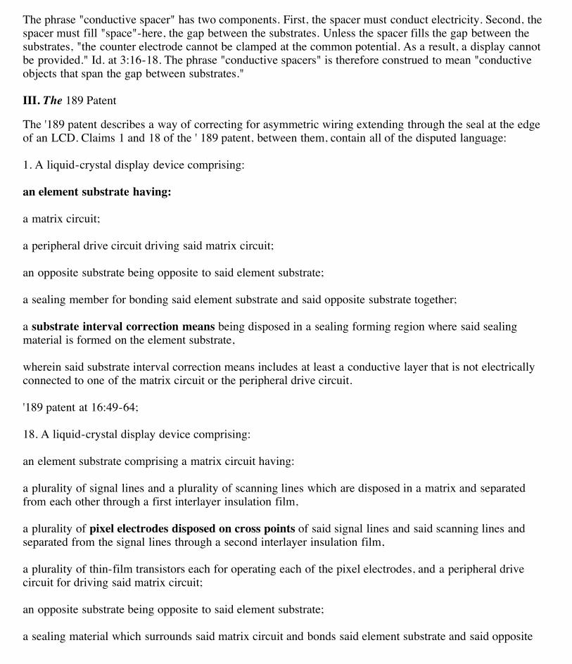
The '189 patent describes a way of correcting for asymmetric wiring extending through the seal at the edgeof an LCD. Claims 1 and 18 of the ' 189 patent, between them, contain all of the disputed language:
1. A liquid-crystal display device comprising:
an element substrate having:
a matrix circuit;
a peripheral drive circuit driving said matrix circuit;
an opposite substrate being opposite to said element substrate;
a sealing member for bonding said element substrate and said opposite substrate together;
a substrate interval correction means being disposed in a sealing forming region where said sealingmaterial is formed on the element substrate,
wherein said substrate interval correction means includes at least a conductive layer that is not electricallyconnected to one of the matrix circuit or the peripheral drive circuit.
'189 patent at 16:49-64;
18. A liquid-crystal display device comprising:
an element substrate comprising a matrix circuit having:
a plurality of signal lines and a plurality of scanning lines which are disposed in a matrix and separatedfrom each other through a first interlayer insulation film,
a plurality of pixel electrodes disposed on cross points of said signal lines and said scanning lines andseparated from the signal lines through a second interlayer insulation film,
a plurality of thin-film transistors each for operating each of the pixel electrodes, and a peripheral drivecircuit for driving said matrix circuit;
an opposite substrate being opposite to said element substrate;
a sealing material which surrounds said matrix circuit and bonds said element substrate and said opposite
3/3/10 1:57 AMUntitled Document
Page 16 of 26file:///Users/sethchase/Desktop/Markman/htmlfiles/2006.03.27_SE…TOR_ENERGY_LABORATORY_CO_LTD_v._CHI_MEI_OPTOELECTRONICS_CO.html
substrate together;
a substrate interval correction means being formed in a sealing forming region where said sealing material isformed on said element substrate, said substrate interval correction means having:
at least a conductive layer comprising a same material as the scanning lines, said first interlayer insulationfilm, and said second interlayer insulation film,
wherein said conductive layer, said first interlayer insulation film, and said second insulation film areformed in different layers from each other,
wherein said conductive layer is not electrically connected to any one of the matrix circuit and theperipheral drive circuit.
'189 patent at 18:44-19:8.
A. "an element substrate having / an element substrate ... having"
Defendants propose that the phrase "element substrate" should be construed to mean "a single piece ofmaterial on which the matrix and peripheral drive circuits are integrally formed." Plaintiff proposes that thephrase should be construed to mean "the substrate with thin-film transistors." The parties' constructionsdiffer in two relevant respects. First, defendants' construction requires that the matrix and peripheral drivecircuits be "integrally formed" on the substrate. Second, defendants' construction requires that the elementsubstrate be made of a "single piece of material."
1. Integrally Formed
Although the parties dispute whether the matrix and peripheral drive circuits must be "integrally" formed onthe element substrate, it is not clear from the intrinsic record what the term "integrally" means. The patentappears to use the word and its variants in two senses. Claims 11 and 20 illustrate the first sense, whichsuggests that two elements are formed at the same time or as part of the same fabrication step. Claim 11requires that the external wiring elements be "formed integrally with said first conductive layer"-in otherwords, that the external wiring be formed as part of the same fabrication step during which the firstconductive layer is formed. '189 patent at 17:66-67. The first sense does not appear to apply to defendants'proposed construction, which relates to the peripheral circuit as a whole and not to any single circuitelement.
The word "integral" and its variants are used in a second, broader sense in several places in thespecification. The "Field of the Invention" section describes the patented invention as relating to "aperipheral circuit integral type liquid-crystal display device." Id. at 1:9-10 (emphasis added). Thedescription of related art describes the prior art giving rise to the need for the patented invention as having"a peripheral drive circuit and a display section [which] are integrated on a panel." Id. at 1:65-66 (emphasisadded). The prior art is also described as follows: "the peripheral drive circuit integral type active matrixliquid-crystal display device in accordance with the second conventional example shown in FIG. 17 has aperipheral drive circuit disposed inside the sealing material region 17." Id. at 2:35-39. The Summary ofInvention states that "an object of the present invention is to provide a peripheral drive circuit integral typeliquid-crystal display device which is excellent in image quality and high in reliability." Id. at 3:19-21.Also, the beginning of the detailed description states as follows: "FIG. 1 is a front view showing an outline
3/3/10 1:57 AMUntitled Document
Page 17 of 26file:///Users/sethchase/Desktop/Markman/htmlfiles/2006.03.27_SE…TOR_ENERGY_LABORATORY_CO_LTD_v._CHI_MEI_OPTOELECTRONICS_CO.html
of an element substrate of an active matrix type liquid-crystal display device in accordance withembodiments 1 to 5 of the present invention, in which a peripheral drive circuit is integral with a displaysection." Id. at 5:25-29. In contrast, the specification describes an alternate prior art configuration in which"the peripheral drive circuit which is made up of a semiconductor integrated circuit is attached externally toa liquid-crystal panel through the tape automatic bonding (TAB) technique or the chip on glass (COG)technique." Id. at 1:27-30.
Based on the preceding examples, "integral type" LCD suggests at least two separate meanings. The firstsuggests that the peripheral circuits are deposited directly on the glass, rather than attached through the "tapeautomatic bonding" or "chip on glass" techniques. The second suggests that the peripheral circuit is locatedinside the sealing material-thus "integrated" within the LCD rather than connected externally via wiring theextends out through the sealing region.
At oral argument, defendants clarified that their proposed construction seeks to impose the first requirement-that the peripheral drive circuits be "integrally formed" (directly deposited) on the same transparent materialthat underlies the matrix of pixel electrodes. Neither party took a position on whether the peripheral circuitmust be located inside the sealing material. The court will therefore limit its discussion to whether theperipheral circuit must be directly deposited on the same material that underlies the electrodes.
The full claim element in dispute, including sub-elements, reads as follows: "an element substrate having: amatrix circuit; a peripheral drive circuit driving said matrix circuit." Id. at 50-52. This language, without anyfurther construction, indicates that the element substrate must "have" both a matrix circuit and a peripheraldrive circuit-in other words, that the peripheral drive circuit and matrix circuits are included within theelement substrate. See, e.g., Crystal Semiconductor Corp. v. TriTech Microelectronics Int'l, 246 F.3d 1336,1348 (Fed.Cir.2001) (noting that "having" is a transitional term of art, denoting inclusion, which may beeither open- or closed-ended). The claim does not, however, expressly require that the peripheral drivecircuit or matrix circuit be incorporated into the substrate in any particular way.
Turning to the specification, although several passages characterize the claimed device as an "integral-type"LCD, nothing in the specification limits the claims to that type of device. The invention, rather, is limited todisplays with asymmetrical wiring crossing the sealing region; without an asymmetry, there is nothing to"correct." Although defendants argue that the asymmetry only exists when "the drive and matrix circuits areintegral to the same substrate," nothing in the specification supports such a broad assertion. See Defs.' Briefin Opposition at 20.
Defendants also argue that the prosecution history supports their construction. In the Notice of Allowance,the examiner distinguished a piece of prior art, U.S. Patent No. 5,396,356 ("Fukuchi") on the grounds that"either of Fukuchi's LCD substrates-alone-does not appear to contain a matrix circuit (rather, the electrodeson both substrates in combination form a matrix circuit), a peripheral drive circuit (i.e., such circuit must beformed on the same substrate that the matrix circuit is formed)." Mosko Dec., Exh. S at 3. In the quotedpassage, the examiner does not appear to have been considering the precise question currently before thecourt-exactly how the drive circuit is incorporated into the substrate-but the separate question of whether thedrive circuit is part of the TFT substrate at all, or is located on the opposing substrate. Based on the claimlanguage, as the examiner correctly noted, both the matrix circuit and the peripheral circuit must beincorporated into the element (TFT) substrate.
In sum, nothing in the intrinsic record before the court supports defendants' contention that the drive circuit
3/3/10 1:57 AMUntitled Document
Page 18 of 26file:///Users/sethchase/Desktop/Markman/htmlfiles/2006.03.27_SE…TOR_ENERGY_LABORATORY_CO_LTD_v._CHI_MEI_OPTOELECTRONICS_CO.html
be "integrally formed" on the substrate.
2. Single Piece of Material
Based on the papers submitted in connection with the claim construction hearing, defendants' contention thatthe substrate must be made of a "single piece of material" is ambiguous. The court can conceive of twopossible meanings. First, defendants may be contending that "substrate" refers only to the transparent sheeton which the circuitry for the LCD is formed, and not to the final panel that is assembled into the LCD(which includes circuit elements, including the peripheral drive circuit and the matrix circuit). Second,defendants may be contending that the transparent sheet must in all cases be made from a single piece ofmaterial, as opposed to a composite or laminate, or multiple pieces of material arranged horizontally likefloor tiles or squares on a chessboard.
With respect to the first meaning, as just discussed, the claims require that the element substrate "have"-thatis, incorporate-the peripheral drive circuit and the matrix circuit. Defendants do not suggest that the matrixcircuit and peripheral drive circuit are made of a single material; indeed, as discussed in connection with the'258 patent, the circuitry typically consists of many layers of conductive and insulating material. The"substrate" contemplated by the claim thus consists of multiple pieces of material.
It is true that some language in the specification appears to equate "substrate" with the transparent materialon which the circuit elements are formed. See, e.g., '189 patent at 7:22-23 ("a substrate 201 such as a quartzsubstrate or a glass substrate"). As with the '995 patent, discussed infra, the word "substrate" is used to referinterchangeably to the clear material on which circuit elements are formed and to the final component of theLCD panel that consists of the clear material and any circuitry attached or deposited thereon.
With respect to the second meaning, at oral argument defendants clarified that their proposed constructionfocuses on the question of whether the substrate can be made of multiple pieces of material arrangedhorizontally, like tiles. The only evidence provided by defendants in support of this construction are theportions of the specification describing the type of material from which the substrate is made, such as quartzor glass, and a dictionary entry which defines substrate as "[t]he underlying material upon which a device,circuit, or epitaxial layer is fabricated." Mosko Dec., Exh. R at 515. None of these references makes anymention of the number of pieces of material that may make up a substrate. The court therefore declines tolimit the phrase "element substrate" to a "single piece of material."
Neither party offers a convincing argument why the claim language would benefit from further definition.The court therefore adopts a construction based on the claim language. The court construes the phrase"element substrate" to mean "the substrate having a matrix circuit and a peripheral drive circuit driving saidmatrix circuit." See '189 patent at 16:51-53.
B. "substrate interval correction means"
Plaintiff argues that the phrase "substrate interval correction means" should be construed to mean a"structure located in the region of the sealing material where there is no conductive material that isconnected to any electrical circuit." Defendants argue that the phrase should be construed to mean "astructure designed to displace the sealing material by the same amount that the sealing material at acorresponding location is displaced."
Plaintiff's proposal is irreconcilable with the language of the claim. First, plaintiff's construction omits any
3/3/10 1:57 AMUntitled Document
Page 19 of 26file:///Users/sethchase/Desktop/Markman/htmlfiles/2006.03.27_SE…TOR_ENERGY_LABORATORY_CO_LTD_v._CHI_MEI_OPTOELECTRONICS_CO.html
notion of "correction." Placing a "structure" in the portions of the seal region where no wiring lines exist,with no restriction on the size or shape of the structure, will not necessarily "correct" anything. Also, theadditional requirement of plaintiff's proposed construction-that the interval correction means not containconductive material that is connected to any electrical circuit-is already expressly required by the finalelement of claim 1: "said substrate interval correction means includes at least a conductive layer that is notelectrically connected to one of the matrix circuit or the peripheral drive circuit." Id. at 16:61-64 (emphasisadded). The matrix circuit and the peripheral drive circuit are the only two circuits expressly named in theclaim. Plaintiff's proposed construction therefore omits a limitation that it should include and includes alimitation that it should omit.
Defendants' proposed construction is closer to what the claim requires, but is unclear in two respects. First,defendants argue that the interval correction means "displaces" the sealing material. Neither the claims northe specification uses the word "displace" or provides any guidance as to its meaning. Second, defendantsargue that the interval correction means must displace the sealing material by "the same amount" as "at acorresponding location." The definition does not make clear what the proper "corresponding location" is.
Looking at the disputed language, "substrate interval correction means," has two elements. First, the meansmust "correct." Second, the means must correct the "substrate interval." The problem which is the subject ofthe '189 patent is a lack of uniformity in the interval between the substrates as a result of asymmetry in thewires crossing the sealing region. See, e.g., id . at 2:43-52 ("the wiring structure has no symmetry withrespect to top and down as well as right and left .... It is difficult to make an interval between the substratesuniform"). The '189 patent solves the problem of asymmetry by placing compensating structures in the areasof the sealing forming region where no wires cross.
The proper construction of the disputed term is "a structure, located in the areas of the sealing formingregion where no wires cross, which compensates for the asymmetry in the wires crossing the sealingregion."
C. "a plurality of pixel electrodes disposed on cross points"
Plaintiff argues that "a plurality of pixel electrodes disposed on cross points" should be construed to mean"pixel electrodes arranged such that each transistor controlling a pixel electrode is located at the intersectionof a signal and a scanning line"; plaintiff contends that the word "on" should be construed in the sense of"on the corner" of two streets. Defendants argue that the phrase should be construed to mean "pixelelectrodes atop the intersection of the signal and scanning lines." The parties' constructions differ in onlyone relevant respect. In plaintiff's construction, it is the transistor controlling each pixel that is located at theintersection of the lines. In defendants' construction, the pixel electrode itself must not only be at theintersection, but "atop"-i.e., directly above-the intersection.
The use of the word "on" in the claims, rather than "at," strongly favors defendants' proposed construction.Plaintiff's gas station analogy notwithstanding, the word "on" generally denotes more than just proximity; anobject is "on" another object when it is above or supported by that object.
The specification is fully consistent with defendants' proposed construction. Several passages are relevant tothe geometry of the electrodes. The first passage appears at column 2, line 62 to column 3, line 1:
Also, in the pixel element, a most projected portion is in a region where the scanning lines and the signal

3/3/10 1:57 AMUntitled Document
Page 20 of 26file:///Users/sethchase/Desktop/Markman/htmlfiles/2006.03.27_SE…TOR_ENERGY_LABORATORY_CO_LTD_v._CHI_MEI_OPTOELECTRONICS_CO.html
lines are superimposed one on another, and in the region, not only the scanning line, the signal line, aninter-layer insulation film for separating those lines from each other, but also a pixel electrode, a blackmatrix and so on are laminated one on another.
Id. at 2:62-3:1 (emphasis added). The second passage, between column 4, line 62 and column 5, line 2,states as follows:
It should be noted that because in the region where the signal lines 105 and the scanning lines 106 aresuperimposed one on the other, pixel electrodes, a black matrix and so on are further laminated one onanother, the substrate interval formation means may be also designed so that the pixel electrodes, the blackmatrix and so on are laminated one on another in the formation means.
Id. at 4:62-5:2 (emphasis added). These two passages describe the points of highest elevation on the lowersubstrate, where the circuit elements in the middle of the matrix are stacked so high that "the scanning linesand the signal lines are short-circuited between the top and the bottom through the spacers, thereby causingthe point defect and the line defect." Id. at 3:12-14. In order to accommodate the high elevation, within theinterval correction means "the first support members 301, 302 and 303 and the second support members 701are designed so as to be superimposed one on the other, thereby being capable of making the step of thesubstrate interval maintaining means nearly equal to the height of the region in which the thickness of thematrix circuit is maximum." Id. at 4:51-56. The cited language corresponds to embodiments 4 and 5 in thepatent, as depicted in Figures 12 through 15. In embodiments 4 and 5, the pixel electrode is disposed "atop"the intersection of signal and scanning lines.
The third relevant passage consists of Figure 2 and its accompanying narrative, which shows how the matrixcircuit is formed in Embodiment 1. Of particular note is Figure 2E, showing the completed pixel circuit. InFigure 2E the pixel electrode, 228, is located directly above the gate electrode, 209, of the pixel TFT. Seealso id. Fig. 2A. The gate electrode, in turn, is a part of the scanning line 302. Id. at 8:10-12. Similarly, theother two electrodes for the pixel TFT, 224 and 225, which are also located directly below the pixelelectrode, are part of the signal lines 303. Id. at 9:28-40. In Embodiment 1, as well as in Embodiments 4 and5, the pixel electrode thus appears to be directly atop the intersection of the signal and scanning lines.
The court therefore adopts defendants' proposed construction: "a plurality of pixel electrodes disposed oncross points" is construed to mean "pixel electrodes atop the intersection of the signal and scanning lines."
IV. The '995 PatentFN3
FN3. The disputed claims from the '995 patent are actually found in a reexamination certificate, number4,691,995 C1. Neither party argues that the fact of the reexamination has any bearing on the properinterpretation of the claims. For the sake of clarity, citations to the reexamination certificate will be in theform "'995 patent C1 at X:XX."
The '995 patent describes a system and method for filling an LCD with liquid crystal material. Claim 62contains all of the disputed terms:
A liquid crystal filling method comprising:

3/3/10 1:57 AMUntitled Document
Page 21 of 26file:///Users/sethchase/Desktop/Markman/htmlfiles/2006.03.27_SE…TOR_ENERGY_LABORATORY_CO_LTD_v._CHI_MEI_OPTOELECTRONICS_CO.html
(1) a step of preparing first and second substrates provided with active elements;
(2) a step of placing an amount of liquid crystal on plural locations of the first substrate;
(3) a step of laying the second substrate on the first substrate coincident with each other;
(4) a step of applying pressure to the second substrate toward the first substrate so that the liquid crystal isextended between the first substrate and the second substrate without overflowing; and
(5) a step of making a sealing structure on the periphery of the first and second substrates.
'995 patent C1 at 8:3-16.
A. "first substrate"
Plaintiff proposes that "first substrate" be construed to mean "the substrate in a single liquid crystal displaydevice on which liquid crystal material is deposited." Defendants argue that the phrase should be construedto mean "the single piece of material onto which liquid crystal is deposited." The proposed constructionsdiffer in two respects: (1) defendants' construction limits "substrate" to a single piece of material; and (2)plaintiff's construction limits the invention to a "single liquid crystal" display device.
As with defendants' proposed construction of "substrate" in the context of the '189 patent, defendants'principal argument is that a substrate cannot consist of multiple pieces of material tiled horizontally.FN4
FN4. The court notes that the '995 patent, like the '189 patent, uses "substrate" loosely to refer either to theclear sheet on which circuit elements are formed, or to the completed panel which is assembled into theLCD display.
The claim language supports both meanings. Claim 62 includes "(1) a step of preparing first and secondsubstrates provided with active elements." '995 patent C1 at 8:4-5. The phrase "provided with" is somewhatunclear; it is not evident whether the "active elements" are intended to be viewed as incorporated into (andthus part of) the substrate, or whether they are intended to be viewed as separate elements that are attachedto the "substrate"-the underlying transparent sheet.
The specification also suggests both senses of the word "substrate." On one hand, column 2, lines 53-54states that "[t]he substrates 1 and 1' are made of glass pane such as Corning 7059." Column 4, lines 10-14states that "[i]n place of the hard glass substrate, a flexible substrate can be used, e.g., glass sheet of 0.3 to0.6 mm thickness cured with chemical reinforcing treatment, a transmissive heat-proof organic resin sheetsuch as polyimide, PAN, PET, or the like."
On the other hand, column 1, lines 29-31 states that "[o]ut of processing steps to manufacture the display,charging step for filling the thin cavity [between substrates] without involving bubbles requires dexterity."According to this passage, the "charging step," which is the subject of the '995 patent, takes place after thesubstrates are "process[ed]" to include circuit elements. Column 1, lines 14-19 states that "[o]ne of thesubstrates is made light transmissive and the other is made reflective so that optical characteristics as seen

3/3/10 1:57 AMUntitled Document
Page 22 of 26file:///Users/sethchase/Desktop/Markman/htmlfiles/2006.03.27_SE…TOR_ENERGY_LABORATORY_CO_LTD_v._CHI_MEI_OPTOELECTRONICS_CO.html
from the transmissive side can be changed by controlling the electric field applied on the liquid crystalbetween the substrates." For a substrate to be made "reflective," or for there to be an "electric field," thesubstrate must consist of more than a single transparent piece of material. Column 2, lines 64-65 states that"[t]he electrode of the lower substrate 1 is oriented at its upper surface." The electrode is "of" the substrate,not "on" or "attached to."
Finally, at column 2, lines 59-63 the patent explains that the depiction of a "substrate"in the figures is to beviewed as a shorthand representation for the entire finished LCD panel: "[a]lthough, in the figures, only apair of substrates is shown, descriptions are dispensed with for the electrodes, filters, oriented films, shadowmasks, active elements or so on, fearing confusion between element in the view." Id. at 2:59-63. This phrasesuggests that while "substrate" in one sense has a narrow meaning-referring only to the sheet of material onwhich the circuit elements and filters are formed-for purposes of the patent figures and specification,"substrate" should be understood to include those additional elements.The specification is explicitly open-ended about the materials that make up the substrate. Column 4, lines10-14 states that "[i]n place of the hard glass substrate, a flexible substrate can be used, e.g., glass sheet of0.3 to 0.6 mm thickness cured with chemical reinforcing treatment, a transmissive heat-proof organic resinsheet such as polyimide, PAN, PET, or the like." Although the specification does not expressly list asubstrate consisting of horizontally tiled pieces of material, it does not rule out that possibility. The courttherefore has no basis for imposing defendants' suggested limitation. The phrase "first substrate" does notrequire further construction.
The court will consider plaintiff's argument that the substrate is limited to a "single liquid crystal" device inthe next section.
B. "a step of placing an amount of liquid crystal on plural locations on the first substrate"
Plaintiff argues that "a step of placing an amount of liquid crystal on plural locations on the first substrate"should be construed to mean "depositing an amount of a liquid crystal material in multiple locations on asubstrate." Defendants argue that the phrase should be construed to mean "depositing an amount of liquidcrystal material in multiple locations on a substrate." The parties' constructions differ in only one respect:whether the invention is limited to displays filled with "a" liquid crystal material-a single type.
The parties have reversed roles for this claim term, plaintiff arguing for a limitation based on the descriptionof the invention in the specification, and defendants arguing that the claim language is broader than what isexpressly described. Plaintiff notes that the specification describes only one type of liquid crystal material-"octyl-oxy-benzyli-dene-amino-methylebuthyl-benzoate." Id. at 2:66-67. The specification introduces thisexample by stating that "[o]n the oriented surface is placed an amount of liquid crystal 2 such as S8 (octyl-oxy-benzyli-dene-amino-methylebuthyl-benzoate)." As with other patent terms construed in this order andin this patent (such as "substrate," supra ), the language in the specification is deliberately open-ended,allowing the claims to encompass other liquid crystal materials. The court will not limit the scope of theclaims to the embodiments in the specification unless there is some reason to do so.
Plaintiff argues that the claims should be read only to include other single liquid crystal materials. Asdefendants note, however, the claims do not require placing an amount of "a" liquid crystal material; rather,they require placing "an amount of liquid crystal material."

3/3/10 1:57 AMUntitled Document
Page 23 of 26file:///Users/sethchase/Desktop/Markman/htmlfiles/2006.03.27_SE…TOR_ENERGY_LABORATORY_CO_LTD_v._CHI_MEI_OPTOELECTRONICS_CO.html
Plaintiff also argues that the prior art, in which an already-sealed LCD is filled with liquid crystal materialthrough capillary action, can only accommodate a single liquid crystal material. If so, then the claimedinvention has a further advantage over the prior art: the ability to accommodate multiple different materials.
Finally, plaintiff argues that using the claimed invention with multiple liquid crystal materials wouldeliminate the "efficiencies" of the claimed invention, such as the ability to fill the LCD more quickly.Plaintiff provides no basis, either in the intrinsic record or through extrinsic testimony, for reaching thatconclusion.
The court therefore adopts defendants' proposed construction, "depositing an amount of liquid crystalmaterial in multiple locations on a substrate".
C. "preparing first and second substrates provided with active elements"
Plaintiff proposes that "preparing first and second substrates provided with active elements" be construed tomean "preparing the first and second substrates such that at least one substrate has active elements."Defendants counter that the phrase should be construed to mean "preparing the first and second substrates sothey both have active circuit elements, which are components (such as transistors) whose operation involvesthe activity of a semiconductor junction." Plaintiff does not dispute defendants' definition of "activeelement." Rather, plaintiff argues that both substrates need not have active elements.
The grammar of the disputed element is certainly awkward. Slight alterations of the language wouldunequivocally support both parties positions. For example "providing first and second substrates with activeelements" or "preparing first and second substrates with active elements" would more clearly supportdefendants' construction. Alternatively, "preparing first and second substrates, including active elements"and similar variations would comport with plaintiff's construction. As drafted, the language defies easyunderstanding.FN5
FN5. The court deplores the sloppy claim language that disregards fundamental rules of grammar. As ageneral rule poorly drafted language is entitled to a narrow meaning. Athletic Alternatives, Inc. v. PrinceMfg., Inc., 73 F.3d 1573, 1581 (Fed.Cir.1996); see also Ethicon Endo-Surgery Inc. v. United States SurgicalCorp. ., 93 F.3d 1572, 1581 (Fed.Cir.1996). If read literally, adhering to proper grammatical construction,the phrase "provided with active elements" clearly modifies "first and second substrates," thus indicatingthat both substrates must have active elements. If plaintiff really meant what it now argues, the draftershould have used language such as "preparing a first substrate and a second substrate at least one of whichis provided with active elements". While it is axiomatic that the drafter is his own lexicographer, thecorollary principle should also control: the drafter is his own grammarian and he is bound by his owngrammar whether good or poor. Nonetheless, in this case it would appear that the drafter's poor choice iscontrary to the overall context of the patent (which does not devote any significant discussion to thepreparation of the substrates), the relationship of independent claims such as claim 62 to narrower dependentclaims such as claim 64, and the examiner's comments during prosecution, all of which favor the broaderconstruction.
The claims depending from claim 62 help to resolve the ambiguity. Claim 64 covers "[a] method accordingto claim 62, wherein active elements are provided with the first substrate." '995 patent C1 at 8:19-20. Underdefendants' proposed construction, claim 64 would be completely superfluous, as claim 62 already would

3/3/10 1:57 AMUntitled Document
Page 24 of 26file:///Users/sethchase/Desktop/Markman/htmlfiles/2006.03.27_SE…TOR_ENERGY_LABORATORY_CO_LTD_v._CHI_MEI_OPTOELECTRONICS_CO.html
require that both the first and second substrates have active elements. While defendants correctly point outthat the doctrine of claim differentiation does not override unambiguous claim language, the meaning of thedisputed element in this case is unclear. Claim 64 thus provides helpful guidance.
The file history also tends to support plaintiff's construction. The examiner noted twice during prosecutionthat " '[a] step of preparing first and second substrates provided with active elements' is understood by theexaminer to be satisfied when either or both of the substrates have active elements." Harris Dec., Exh. 8 at9; id., Exh. 9 at 7. Defendants argue that the views of the examiner should be given little weight, and thatplaintiff should not benefit from allowing the confusing language to remain in the claims. The fact that theexaminer adopted plaintiff's interpretation, however, may have discouraged plaintiff from amending.
The court therefore construes the disputed phrase to mean "preparing the first and second substrates suchthat at least one substrate has active elements."
D. "sealing structure"
Plaintiff argues that "sealing structure" should be construed to mean "structure helping to contain the liquidcrystal material within the cavity between the two substrates of a liquid crystal display." Defendants counterthat the phrase should be construed to mean "a tight and perfect closure made after the second substrates[sic] is laid on the first, to protect the liquid crystal in an LCD device from impurities." The parties'constructions differ in several respects, including the function of the seal, the time at which the seal isformed, and the requirement that the seal form a "tight and perfect fit."
1. Function of the Seal
Plaintiff contends that the sealing structure works in concert with a "fiber barrier" to contain the liquidcrystal material. See id. at 3:45-48. In support of this argument, plaintiff cites a part of the specification:"[t]he amount of the liquid crystal has to be suitably prescribed to avoid falling short of prevailing throughthe desired area while overflow is avoided by virtue of the barrier and the sealing." Id. at 3:59-62.Defendants cite a different part of the specification to show that only the fiber barrier is meant to come intocontact with the sealing material: "[t]o avoid overextension of the liquid crystal and contact of the liquidcrystal with the sealing resin, a fiber barrier 18 of 1 to 3 micron may be placed around the liquid crystal,especially at the corner." Id. at 3:45-48.
The court agrees that the cited passages suggest different and contradictory uses for the "sealing" or "sealingresin." The confusion stems from the fact that there are two separate structures labeled "sealing" in thespecification. The first, the "sealing resin" or "thermosetting resin" is applied to the upper substrate beforethe two substrates are brought together. Id. at 2:68-3:3; 3 :41-48. Based on the description of the sealingresin, it appears to correspond to element 19 in Figure 1, but is not referenced by number in thespecification. The term "thermosetting" suggests that the sealing resin "sets," or hardens, on exposure to heatthat is applied during the assembly process. See id. at 3:11-16 (describing the application of temperaturesbetween 70 and 150 degrees C). The purpose of the "thermosetting" or "sealing" resin is apparently to jointhe two substrates together. Id. at 3:41-44 ("the sealing resin is elongated at the corner region of thesubstrate 1' so that the substrates 1 and 1' are joined with an area of 1 to 15 mm 2 surrounded by theelongated resin."); id. at 3:2 (referring to the thermosetting / sealing resin as an "epoxy" resin-a glue); id. at4:62-66 (claiming the additional steps of "placing an amount of adhesive on the peripheral portion of thefirst substrate," "wherein said adhesive is epoxy resin").
3/3/10 1:57 AMUntitled Document
Page 25 of 26file:///Users/sethchase/Desktop/Markman/htmlfiles/2006.03.27_SE…TOR_ENERGY_LABORATORY_CO_LTD_v._CHI_MEI_OPTOELECTRONICS_CO.html
The second, a "plastic sealing material 9 as shown FIG 1(E)," is applied after the two substrates have beenbrought together. Id. at 4:1-3 & fig. 1(E). The purpose of the plastic sealing material is "security." Id. at 4:1.
The language cited by plaintiff is puzzling, as it does not clearly fit with either "sealing" material: "overflowis avoided by virtue of the barrier and the sealing." Id. at 3:61-62. On one hand, the language appears in thedescription of the process prior to the application of the "plastic sealing material," suggesting that the word"sealing" is intended to refer to the "sealing resin." On the other, as just discussed, the passage cited bydefendants suggests that the sealing resin is not intended to come into contact with the liquid crystalmaterial. In any event, the use of "sealing structure" in the claims resolves any ambiguity.
The phrase "sealing structure" in the claims apparently refers to the second, "plastic" sealing material. Thegrammar of the claims suggests this conclusion; the "sealing structure" is created at the joint (singular)"periphery" of both substrates together, which is not possible until after the two substrates have beenbrought together and pressure applied. See '955 patent C1 at 8:11-16. In contrast, the "sealing resin" isapplied to the first substrate before the substrates are brought together or pressure applied. The originalclaims of the patent further support this construction. Claim 5, which is the prototype for all of theindependent claims added during reexamination, concludes with the step of "making a sealing structure onthe periphery of the substrates." '955 patent at 4:50-51. Claims 8 and 9, which depend from claim 5, add theadditional step of "placing an amount of adhesive on the peripheral portion of the first substrate," "whereinsaid adhesive is epoxy resin." Id. at 3:62-66. The only "resin" mentioned in the specification is the "sealingresin ." Based on claim differentiation and consistent usage, the "sealing structure" in claim 5, and in eachof the added independent claims which are modeled on claim 5, refers to the plastic sealing material and notto the sealing resin.
The function of the plastic sealing material is to provide "security." This concept is broad, and arguablyencompasses both of the parties' proposed functions: keeping the liquid crystal material in, and keepingimpurities out. The specification does not provide any further restrictions that require the court to chooseone or the other.
2. Time of Formation
For the reasons just discussed, the "sealing structure" is applied to both substrates jointly, after they havebeen brought together and subjected to heat and pressure.
3. Tight and Perfect Fit
Defendants offer no support for the "tight and perfect fit" limitation in the language of the claims or thespecification. Instead, they refer to a dictionary definition of "seal." See Mosko Dec., Exh. X at 1052.Absent any motivation to impose the requirement of a tight and perfect fit in the intrinsic record, the courtfinds that the phrase "sealing structure" means "a structure, made after the second substrate is laid on thefirst, which may help to contain the liquid crystal material within the cavity between the two substrates or tokeep impurities out."
E. "the periphery"
Defendants contend that "the periphery" should be construed to mean "the outermost edge of a substrate."Plaintiff counters that the phrase is sufficiently clear and requires no further construction.
3/3/10 1:57 AMUntitled Document
Page 26 of 26file:///Users/sethchase/Desktop/Markman/htmlfiles/2006.03.27_SE…TOR_ENERGY_LABORATORY_CO_LTD_v._CHI_MEI_OPTOELECTRONICS_CO.html
Defendants' proposed construction would exclude the preferred embodiment disclosed in the specification, atruly extraordinary result. As just discussed, the claims require "making the sealing structure on theperiphery of the first and second substrates." See '995 patent C1 at 8:15-16. Regardless of which "sealing"material the claim references-either the "sealing resin" shown as element 19 or the "plastic sealing material"shown as element 9-the sealing structure is not located at the "outermost edge" of the lower substrate. See'995 patent at Figs. 1(D)-(E). The meaning of the term "periphery" is not so narrow as to require that theclaims be construed to exclude the preferred embodiment. The court accordingly declines to adoptdefendants' construction, and will instead rely on the unadorned claim language.
F. "the liquid crystal is filled ... so as not to overflow / the liquid crystal is extended ... withoutoverflowing"
Finally, defendants argue that the phrases "filled ... so as not to overflow" and "extended ... withoutoverflowing" should be construed to mean "adding a precise amount of liquid crystal to completely fill anLCD, without any excess, when the substrates are placed together." Plaintiff counters that the claimlanguage is sufficiently clear and does not require further construction.
The phrases "precise amount," "completely fill," and "without any excess" are completely absent from thespecification and claims. The court will therefore not provide further construction as defendants request.
CONCLUSION
For the reasons stated above, the court construes the disputed terms as indicated in the table at the outset ofthe discussion.
IT IS SO ORDERED.
N.D.Cal.,2006.Semiconductor Energy Laboratory Co., Ltd. v. Chi Mei Optoelectronics Corp.
Produced by Sans Paper, LLC.