semi-solid slurry formation via liquid metal...
TRANSCRIPT

SEMI-SOLID SLURRY FORMATION VIA LIQUID METAL
MIXING
A Thesis
Submitted to the Faculty
of the
WORCESTER POLYTECHNIC INSTITUTE
in partial fulfillment of the requirements for the
Degree of Master of Science
in
Materials Science and Engineering
July 2003
by
Matthew M. Findon
________________________________________
APPROVED:
Diran Apelian, Howmet Professor of Engineering, Advisor
Richard D. Sisson, Jr., Professor of Mechanical Engineering, Materials
Science and Engineering Program Head

ii
Abstract
New, economical semi-solid metal (SSM) processes rely on forced convection
during solidification to influence non-dendritic growth. The fundamental mechanisms
that produce SSM microstructures in the presence of forced convection (due to fluid
flow) are not fully understood. The objective of this work is to elucidate these
mechanisms through the use of a new semi-solid slurry-making technique. Employing
an apparatus developed at WPI, two alloy melts are mixed within a static reactor that
induces convection and rapid cooling. Experiments carried out with this apparatus,
named the “Continuous Rheoconversion Process” (CRP), result in globular semi-solid
microstructures throughout a wide range of processing conditions. These conditions
include the superheat in the melts before mixing, cooling rate of the slurry through the
SSM range, and the presence or absence of inoculants in the melts.
The results comprise repeatable sets of semi-solid microstructures having fine
particle size and shape factors approaching unity. Even in the absence of melt
inoculants, uniform distributions of α-Al particle sizes of about 60µm are attainable.
Entrapped liquid is not present in the majority of the samples obtained with the CRP,
and irregular particles that form in the process are of a limited distribution. Variation of
slurry analysis methods indicates that these structures can be obtained consistently for
both thixocasting and rheocasting applications.
The design of the mixing reactor leads to turbulent fluid flow just as
solidification commences. The results suggest that the following factors must be
considered in identifying the mechanisms operating under the above conditions: copious
nucleation of the primary phase; dispersion of nuclei throughout the bulk liquid; and

iii
inhibited remelting of nuclei due to temperature uniformity. In the CRP, these factors
consistently lead to suppression of dendritic growth, significant grain refinement, and
globular slurries. The exact fundamental mechanism leading to this effect is yet to be
uncovered; however it is clear that temperature gradients ahead of the liquid are such
that a cellular, non-dendritic morphology is the most stable growth form. Through
further exploration of the process and identification of the operating mechanisms, future
development of economical, continuous rheocasting methods will be facilitated.

iv
Acknowledgements
First and foremost, I would like to express my gratitude to my thesis advisor,
Prof. Diran Apelian, for his immense support throughout this project, both scientifically
and personally. His wisdom and guidance affected me in such a way as to effect my full
potential as a graduate student here at MPI.
I would also like to thank the entire faculty and staff of MPI for their scientific
support and overall comradery. I especially thank Dr. Riddle for helping to improve my
metallography skills, as well as Dr. Shankar for his helpful instruction concerning image
analysis. Carl Raatikainen was quite helpful with apparatus modifications, and without
him I may have forgotten about all the things that mysteriously got broken in my
presence.
Nick Saddock and Dr. Anacleto de Figueredo deserve mention for the roles they
played in the design and construction of the apparatus used for this work. I also
appreciate the help from Todd Billings and Steve Derosier in Washburn Shops in
making modifications to apparatus components, and I thank Joe Brooks for machining
the reactors.
Finally, I would like to thank Prof. Apelian, Prof. Makhlouf, Prof. Sisson, Dr.
Pan, and Dr. Shankar for being on my thesis committee and considering this work for
the completion of my Master of Science degree.

v
CONTENTS
Abstract……………………………………………………………………………...…..ii
Acknowledgements…………………………………………………………………......iv
List of Figures and Tables……………………………………………………….....…vii
1. Introduction……………………………………………………………………...….1
2. Background…………………………………………………………………..….…..4
2.1. History of semi-solid metal processing……..…………………….………..…...4
2.2. Previously proposed mechanisms for SSM structure formation ……….….....23
3. Research Approach…………………………………………………………….....26
4. Experimental Methodology…………………………………………………..…..28
4.1. The Continuous Rheoconversion Process (CRP) ………………………..…...28
4.1.1. The Apparatus……..……………………….…...……..………..………28
4.1.2. Process Variables……..……………………….….………..…………...37
4.2. Experimental Plan……..………………………………………………….…...38
4.2.1. Preliminary work………..…………………………….……..……….....39
4.2.2. Alloys used ………..………………………………………………..…..39
4.2.3. Slurry collection method.……………………….………..………...…...41
4.2.4. Thixocasting experiments: Variable thermal conditions……………......43
4.2.5. Rheocasting experiments: Immediately quenched slurry …….….….….45
4.2.6. Rheocasting experiments: Various slurry collection temperatures ….....45
4.2.7. Rheocasting experiments: Single slurry collection temperature.…….....46
4.3. Experimental Procedures.…………………………………………………..…47

vi
5. Results and Discussion…………………..……………………..……………….....50
5.1. Thixocasting route……………………..…………………………………...…..50
5.1.1. Variable: Superheat ……………………..…………………………..….50
5.1.2. Variable: Reactor temperature…………………...…………………..….55
5.2. Rheocasting route ……………………..…………………………………..…..60
5.2.1. Immediately quenched slurry ……………………..……………..……..61
5.2.2. Slurry quenched at various SSM temperatures …………………..…….63
(a) Slow cooling rate through SSM range…………...………………...……65
(b) Higher cooling rate with variable grain refinement ………..……..…....67
5.2.3. Slurry quenched at a single SSM temperature ……..……………..……73
(a) High cooling rate through SSM range……………….…..………..…….75
(b) One melt vs. two melts…………..……………………..…………….…76
5.3. Cooling rate vs. particle size………………………………………...………....78
5.4. Discussion of potential mechanisms...…..………………...………..……….…80
6. Conclusions……………………..…………………....……………….………..…..85
7. References……………………..……………………..……..……….……….….…88
Appendix A: Micrograph gallery………………………….……..…………...……...91
Appendix B: Control experiments – Liquid metal transport tubes…………….….97

vii
LIST OF FIGURES AND TABLES
Figure 1: Viscosity and shear stress vs. fraction solid of (a) dendritic and (b) non-dendritic Sn-15wt%Pb under a continuous shear rate [5]..………....5
Figure 2: (a) Dendritic structure (quenched at 0.36 fraction solid) resulting
from shearing after solidification begins; (b) Non-dendritic structure (quenched at 0.60 fraction solid) resulting from shearing before solidification begins (Alloy: Sn-15%Pb) [1]……………………………….....6
Figure 3: Hysteresis loop of shear stress vs. shear rate in semi-solid A357 slurry [8]….7 Figure 4: Transmission belt cover produced by an SSM process [3]…………………...9 Figure 5: Multilink suspension component produced by an SSM process [3]……….....9 Figure 6: Schematic of the two major semi-solid processing approaches [2]……….....10 Figure 7: SSM structure obtained using the MHD process. Alloy: A356 [2]………... 12 Figure 8: Structure produced by the Microcast-X (MX) process.
Alloy: MarM247 [2]………… ………………………………..………….....14 Figure 9: General steps involved in UBE’s new rheocasting (NRC) process [2]……...15 Figure 10: Typical microstructure obtained with the UBE process.
Alloy: Al-Si-Cu [2]…………………………………….…………...………16 Figure 11: (a) Illustration of the steps involved in the SSR process (b) Typical
thermal history of SSR-processed slurry [2] ……….…………….…...……17 Figure 12: Microstructure of slurry produced using the SSR process.
Alloy: A356 [2] ……….…………….…………….……….….…….……...18 Figure 13: Time-temperature data from original liquid mixing experiment by Nasim
Alem [21]…… ……….…………….…………….………..….……………19 Figure 14: Microstructure obtained from original liquid mixing experiment by Nasim
Alem [21]……………. ……….…………….…………….…………..…....20 Figure 15: SSM microstructure obtained with the SLC process. Alloy: A356 [25]..…21 Figure 16: Sn-15wt%Pb alloy continuously sheared at 3625s-1 in a twin-screw
extruder, and quenched at 13°C below its liquidus temperature [27]…...….24 Figure 17: Early schematic of the Continuous Rheoconversion Process (CRP)…..…..29

viii
Figure 18: Photograph of the CRP apparatus ………………………..…..……….……30 Figure 19: (a) Stopper rod and exit spout; (b) a top-down view of the crucible within
the melting furnace, showing the pull-action solenoid……………………...31 Figure 20: Coiled heating elements used for heating the liquid metal transport tubes...32 Figure 21: “Boot” component of the CRP…...………………...…….…………….…..33 Figure 22: Inner designs of the preliminary (left) and secondary (right) mixing
reactors………….…………...…………….…………….…………….……34 Figure 23: Setup of the third furnace when the reactor is preheated……………...……35 Table 1: Chemical compositions (wt%) and liquidus temperatures (°C) of the alloys
used…………………………….…………….………………………….…….40 Figure 24: Schematic diagrams detailing the solidification paths undergone in the
two experimental phases. Arrows indicate quenching of slurry…………...42 Figure 25: Flow chart of the three sample collection methods………………..……….43 Table 2: Experiments carried out in the “T1” series…………………………….……..44 Table 3: Experiments carried out in the “T2” series…………………………….….....44 Table 4: Experiments carried out in the “R2” series…………………………….....….45 Table 5: Experiments carried out in the “R3” series……………………………..…....47 Table 6: Conditions and thermal results for selected T1 (superheat-variable)
experiments…..……….……..…….…………….…………….……………...51 Figure 26: (a) As-solidified and (b) reheated microstructures from experiment T1-2.
Residence time of reheated slug in SSM range: 38 minutes…………….....52 Figure 27: (a) As-solidified and (b) reheated microstructures from experiment T1-3.
Residence time of reheated slug in SSM range: 25 minutes……………….52 Figure 28: (a) As-solidified and (b) reheated microstructures from experiment T1-4.
Residence time of reheated slug in SSM range: 18 minutes…………….…52 Table 7: Image analysis results for the T1 experiments……………..……..………….53 Table 8: Conditions and thermal results for selected T2 (variable reactor temperature)
experiments…………………..….…………….…………….……………..…56

ix
Figure 29: (a) As-solidified and (b) reheated microstructures from experiment T2-4. Residence time of reheated slug in SSM range: 24 minutes……………..…57
Figure 30: (a) As-solidified and (b) reheated microstructures from experiment T2-5.
Residence time of reheated slug in SSM range: 25 minutes…….………….57 Figure 31: (a) As-solidified and (b) reheated microstructures from experiment T2-6.
Residence time of reheated slug in SSM range: 16 minutes……………..…57 Figure 32: (a) As-solidified and (b) reheated microstructures from experiment T2-8.
Residence time of reheated slug in SSM range: 2 minutes……………..…..58 Table 9: Image analysis results for the T2 experiments……………………...………...59 Figure 33: Microstructures from experiment R1-1. The sample was immediately
quenched in water upon exit from the reactor………………………………61 Table 10: Image analysis results for experiment R1-1…………………………………62 Table 11: Conditions and thermal results for the R2 (slurry quenching I)
experiments……….…………...…………….……….….…………….….…64 Figure 34: Microstructural results from experiment R2-2; slurry samples obtained
at the specified temperatures and times after slurry collection. ………..…..65 Table 12: Image analysis results for experiment R2-2……………..……….……..…...67 Figure 35: Slurries obtained using grain refined A356.2 (above left), SiBloy®
(above right), and non-grain refined A356.2 (bottom). Samples quenched at 600°C (1.8min and 2.0min after collection, respectively) ……….…..….68
Figure 36: Slurries obtained using grain refined A356.2 (above left), SiBloy®
(above right), and non-grain refined A356.2 (bottom). Samples quenched at 590°C (2.3min and 2.8min after collection, respectively). ……….…..…69
Figure 37: Slurries obtained using grain refined A356.2 (above left), SiBloy®
(above right), and non-grain refined A356.2 (bottom). As-solidified structures…………….…………….…………..…………….……………...70
Table 13: Image analysis results for experiments R2-5 through R2-7………….…...…71 Figure 38: R2-5 microstructures at 50X (left) and 200X (right). Sample quenched at
610°C (50 seconds after collection). ……….…………….….……….….…72 Table 14: Image analysis results for the micrographs shown in Figure 38. ………..….73

x
Table 15: Conditions and thermal results for selected R3 (slurry quenching II) experiments…………….…………….…………...…………….…………..74
Figure 39: Microstructures from experiment R3-1; 50X (left), 100X (right)……….....75 Figure 40: Microstructures from experiment R3-4; 25X (left), 50X (right)…………...76 Figure 41: Microstructures from experiment R3-5; 25X (left), 50X (right)…………...76 Table 16: Image analysis results for the R3 experiments…………….………………...77 Figure 42: Particle size as a function of cooling rate of the slurry after exiting
the reactor. As-solidified structures………..……….…...……….…………79 Figure 43: Particle size as a function of cooling rate of the slurry after exiting
the reactor. Slurry structures at 590°C……………….…………..………...79
Figure 44: Schematic of the solid/liquid interface arising from a single growing equiaxed particle ………………………………………………...………....82
Figure 45: Schematic of the solid/liquid interfaces arising from multiple growing,
closely spaced equiaxed particles………………………………………......83 Figure A-1: Experiment R2-2; Tslurry=597°C. (Left) Typical structure throughout
sample; (Right) isolated region of dendritic growth. Note the large size of the dendrite, which likely originated from a small portion of liquid that exited the reactor above its liquidus temperature…………………....91
Figure A-2: Experiment R2-2; Tslurry=590°C. (Left) Typical structure throughout
sample; (Right) isolated region of dendritic growth…………….………..92 Figure A-3: Experiment R2-2; Tslurry=585°C. (Left) Typical structure throughout
sample; (Right) isolated region of dendritic growth. Unusual dendritic morphologies seen throughout the picture at the right……..………..…...92
Figure A-4: Figure A-4: Experiment R2-2; Tslurry=605°C. (Left) Typical structure
throughout sample; (Right) isolated region of dendritic growth………....92 Figure A-5: Experiment R2-2; As-solidified structure. (Left) 25X; (Right) 50X.
The presence of the observed eutectic “pool” was not seen in any other samples, but it could be a normal phenomenon due to liquid segregation. “Chinese script” phase observed within the pool is likely the compound Al8Mg3FeSi6, while the black phase seen above this region is probably Mg2Si…..……….…………….………..….…………….…………….….93

xi
Figure A-6: Experiment R3-2; Tslurry=585°C. (Left) Non-primary phase particle (possibly β-Si) which seems to be nucleating α-Al; (Right) Quenching artifacts near the thermocouple’s stainless steel protection sheath (far right)……… ……….…………….…………….……..…….……….……93
Figure A-7: Experiment R2-2; Tslurry=575°C. (Left) 50X, showing several more
non-primary phase particles resembling β-Si; (Right) 400X, close-up of acicular Al5FeSi intermetallic compound……………..……….….…...94
Figure A-8: SEM micrographs of the primary Si particles observed in Figure A-7
(top); EDX spectrum of the particle in the right-hand picture, showing only the presence of silicon (bottom)……….. ……….…………….…....95
Figure A-9: Experiment R2-2. (Left) Tslurry=575°C (Right) Tslurry=605°C. Well-
developed dendrites observed…………..……….………….………….…96 Figure A-10: (Left) Experiment R3-4, transition zone between globular and
dendritic morphologies; Tslurry=585°C (Right) Experiment R3-5, quenching artifacts adjacent to thermocouple’s stainless steel protection sheath; Tslurry=585°C. ……….…………….…………….…...…………..96
Table B-1: Conditions and thermal data for the tube control experiments………..…..97 Figure B-1: Microstructure obtained when a hot tube was employed
(experiment TC-1). Quenched in water……………….……...…….…….98 Figure B-2: Microstructure obtained when a cold tube was employed
(experiment TC-2). Quenched in water…………….…………………….98

1
1. Introduction
Semi-solid metal (SSM) processing is a promising technology that resulted from
groundbreaking findings in the early 1970’s at the Massachusetts Institute of
Technology [1]. Since the initial discovery, several casting processes have been
developed to exploit the advantages offered by SSM. However, incorporating SSM into
a manufacturing setting is economically challenging, and thus it has for the most part
been a niche area of metal forming. In order to understand how and why the semi-solid
microstructure is obtained, as well as how to produce it with less expensive methods,
much research has been carried out in this field over the past three decades. In recent
years, global research into the field has accelerated in the search for ways to fully realize
the benefits that semi-solid processing can offer.
The main property of semi-solid metal (“slurry”) that renders it superior to
conventional casting processes is the non-turbulent (a.k.a. “laminar” or “thixotropic”)
flow behavior that results when one enters the “two-phase” field of solid plus liquid [1].
Specifically, shearing of semi-solid slurry leads to a marked decrease in viscosity, so
that a partially frozen alloy can be made to flow like a non-Newtonian fluid.
Thixotropic flow behavior arises from the ideal SSM microstructure of small, spherical
α-Al particles suspended in a liquid matrix. In all semi-solid processes, it is imperative
that this microstructure be produced consistently. Moreover, a uniform distribution of
this microstructure throughout a volume of slurry is essential for production of high-
quality components.
When semi-solid slurry rather than superheated liquid metal is used in a casting
process, several advantages are realized [2]. First of all, laminar flow reduces gas

2
entrainment, which is a problem associated with turbulent melt flow. Laminar flow
behavior also allows for the casting of thin-walled sections, which are prevalent in some
of the more complex automotive components like steering knuckles and multilink
suspensions [3]. Furthermore, since the slurry is lower in temperature than molten
metal, die life can be significantly extended by reducing thermal stresses. Solidification
shrinkage is also dramatically decreased due to lower processing temperatures. A
component cast in an SSM process has improved mechanical properties as a result of
lower shrinkage porosity, the absence of entrapped gases, and the enhanced strength of
the casting’s non-dendritic microstructure.
Since the early days of development in the 1970’s, many techniques have been
devised to cast near-net-shape components with semi-solid slurries [2]. Most of these
processes are known as “thixocasting,” in which the semi-solid material is obtained by
partially remelting specially prepared feedstock material. Precursor metal for
thixocasting does not contain the conventional dendritic microstructure; instead it is
comprised of fine, equiaxed primary α-Al particles. Upon partial remelting
(“reheating”), the semi-solid microstructure is obtained, and the material can be used in
a casting operation. The other approach to semi-solid processing is called “rheocasting,”
wherein the slurry is formed directly from the molten state. Also known as “slurry-on-
demand” or SoD, rheocasting is the preferred route for the development of new SSM
processes, since it eliminates the high cost of specially produced feedstock. Perhaps
most importantly, rheocasting is the most logical route to follow for the development of
continuous semi-solid casting applications.

3
The motivation for this work stems from the desire within the SSM community
to develop such a continuous slurry-on-demand approach. In order to do this, we must
first address the scientific issues that are not fully understood. Recently developed semi-
solid forming processes employ some kind of agitation technique to influence the α-Al
particles to grow in a spheroidal, non-dendritic fashion. While these processes work
well, the fundamental mechanisms behind the evolution of SSM structures under these
conditions are not well identified [1]. Once the mechanisms are understood, then it will
be possible to establish the necessary measures to control the process; this is the most
important requirement for scaling up any SoD process.
The questions that need to be addressed in the development of new rheocasting
routes are as follows. First, what are the microstructural mechanisms that lead to a well
globularized semi-solid microstructure under the imposed conditions of forced
convection and copious nucleation? Secondly, how can these mechanisms be
manipulated in order to consistently produce high quality semi-solid material in a
manufacturing setting? These two issues are addressed in this work, based on
experimentation with a new slurry-making technique invented at WPI. This apparatus,
called the “Continuous Rheoconversion Process (CRP),” mixes two separate aluminum
melts within a reactor, resulting in semi-solid slurries having highly globular particle
morphologies. The melt streams undergo forced convection while nuclei are being
formed in very high numbers. A thorough microstructural investigation is presented in
order to identify the mechanisms at work in this novel solidification process.

4
2. Background
This section will present a timeline of the important SSM processing routes that
have been developed over the last thirty years. General processing aspects of SSM will
be described, including the discovery of thixotropic behavior and the differences
between thixocasting and rheocasting. Examples of semi-solid methodologies will be
presented in detail. Lastly, the pertinent microstructural and solidification paradigms
will be laid out in order to provide the context for the present work.
2.1 - History of Semi-Solid Metal Processing
During the course of his PhD research [4], David Spencer documented the initial
findings that led to the discovery of semi-solid processing. He was investigating hot
tearing in a Sn-15%Pb alloy through the use of a special apparatus that measured the
viscosity and shear stress of solidifying metal as a function of fraction solid. This
Couette-type viscometer was comprised of two concentric cylinders with an annular
space, within which the alloy was allowed to partially solidify. As the outer cylinder
was rotated (with the inner one stationary), the material was sheared at various rates, and
values for shear stress and viscosity were recorded.
Ironically, the core property of semi-solid processing was discovered during
Spencer’s research, which was not related to SSM. In the initial hot tearing
experiments, shearing was begun after the metal had begun to solidify, and a
predominantly dendritic structure resulted. In an alternate set of experiments, however,
shear was imposed on the liquid before solidification began, and continued as the liquid
cooled below its liquidus. As a result of this slight modification, the microstructure
5
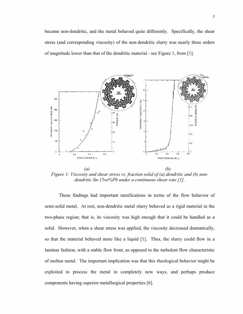
became non-dendritic, and the metal behaved quite differently. Specifically, the shear
stress (and corresponding viscosity) of the non-dendritic slurry was nearly three orders
of magnitude lower than that of the dendritic material - see Figure 1, from [1].
(a) (b) Figure 1: Viscosity and shear stress vs. fraction solid of (a) dendritic and (b) non-
dendritic Sn-15wt%Pb under a continuous shear rate [1].
These findings had important ramifications in terms of the flow behavior of
semi-solid metal. At rest, non-dendritic metal slurry behaved as a rigid material in the
two-phase region; that is, its viscosity was high enough that it could be handled as a
solid. However, when a shear stress was applied, the viscosity decreased dramatically,
so that the material behaved more like a liquid [1]. Thus, the slurry could flow in a
laminar fashion, with a stable flow front, as opposed to the turbulent flow characteristic
of molten metal. The important implication was that this rheological behavior might be
exploited to process the metal in completely new ways, and perhaps produce
components having superior metallurgical properties [6].

6
Laminar flow and thixotropy of semi-solid metal are directly related to
microstructure. In the shearing of the Pb-Sn alloy in Spencer’s experiments, the
microstructure was changed from a dendritic to a non-dendritic morphology. When
shear was applied after solidification began, the structure seen in Figure 2a resulted.
When shear was applied before solidification began (and continued into the two-phase
field), the structure shown in Figure 2b resulted. As mentioned previously, the ideal
SSM or “thixotropic” microstructure is comprised of spherical primary particles of small
diameter suspended in a liquid matrix. Figure 2b is an example of such a
microstructure, from the initial research of SSM at MIT.
(a) (b) Figure 2: (a) Dendritic structure (quenched at 0.36 fraction solid) resulting from
shearing after solidification begins; (b) Non-dendritic structure (quenched at 0.60 fraction solid) resulting from shearing before solidification begins (Alloy: Sn-15%Pb)
[5].
It has been suggested [7] that the rounded primary particles seen above tend to
agglomerate to form a loosely connected skeletal structure, which gives semi-solid
slurry its rigidity when at rest. When shear forces are applied, however, the

7
agglomerates are broken down as the particles physically move past one another;
therefore the viscosity decreases drastically. Once shearing is ceased, the semi-solid
material retains its initial viscosity. A plot of this behavior gives a hysteresis loop,
which is another unique property seen in SSM. Figure 3 [8] shows a plot of such data,
which illustrates how a semi-solid metal is able to recover its solid-like properties after
being handled and deformed like a liquid, or more specifically, when shear rates are
increased and then decreased. The area enclosed by the curve is a direct measure of the
material’s thixotropy.
0.1
1
10
100
0 300 600 900 1200Shear Rate (1/s)
App
aren
t Vis
cosi
ty (P
as)
up
down
590oC fs =0.39
Figure 3: Hysteresis loop of shear stress vs. shear rate in semi-solid A357 slurry [8].
The benefits that semi-solid processing holds over conventional liquid metal
casting result from the flow behavior of the partially solidified metal. The way in which
a metal fills a mold (or die cavity) directly impacts the solidification of the metal; thus,
the properties of the formed part can be enhanced with improved mold filling.

8
Turbulent flow of liquid metal into a die or mold can lead to incorporation of air and
mold gases into the melt [2]. This in turn can lead to both macro- and microporosity,
which negatively affect the mechanical properties of the final part.
There are several reasons that the laminar flow of semi-solid slurries is very
advantageous from a casting standpoint. The first major reason is the elimination of gas
entrapment, resulting in decreased porosity and oxide content in the formed part.
Secondly, since semi-solid metal has lower heat content than superheated molten metal,
there is less solidification shrinkage in the casting. Thus, molds can be filled more
effectively and uniformly, and less post-casting machining is required. As a result, all
semi-solid processes are potentially “near net-shape” processes. The reduced heat
content also lowers the thermal stresses of the casting apparatus (typically a steel die)
that contacts the metal, leading to longer tool life. Also, since the starting material has
the thixotropic microstructure, the microstructure of any part formed with semi-solid
processing is always equiaxed and non-dendritic. The primary α-Al particles typically
have diameters less than 100µm. Therefore, the mechanical properties of the final
component are better than a similar part formed from a conventional casting process.
The net result of the above-described advantages is that semi-solid casting can be
used to produce intricate components with superior mechanical properties. The typical
defects associated with molten metal casting can be circumvented when the
microstructure (and thus the flow behavior) of the slurry is controlled. From an
economic standpoint, it is expected that due to improved tool life, shorter cycle times,
reduced machining, and ability to use less expensive heat treatment schedules, semi-
solid processes will ultimately become as cost-effective as conventional casting routes

9
such as high pressure die casting [9,10]. Perhaps the most attractive attribute of semi-
solid forming, however, is that due to the laminar flow of the slurry, very complex
shapes can be cast, with thin walled sections on the order of millimeters [3]. Figures 4
and 5 show examples of typical components formed by semi-solid processes.
Figure 4: Transmission belt cover produced by an SSM process [3].
Figure 5: Suspension multilink component produced by an SSM process [3].
Soon after the discovery by Spencer, a number of processes were designed to
take advantage of the unique behavior of semi-solid metal slurries. From the very
beginning, these processes all devised novel ways to produce the thixotropic
10
microstructure through some method of vigorous agitation during solidification. It was
hypothesized that the induced agitation broke up (or facilitated the melting off of)
dendrite arms, which then ripened and spheroidized to form a non-dendritic structure
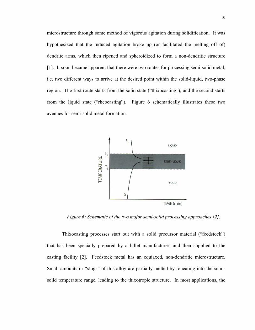
[1]. It soon became apparent that there were two routes for processing semi-solid metal,
i.e. two different ways to arrive at the desired point within the solid-liquid, two-phase
region. The first route starts from the solid state (“thixocasting”), and the second starts
from the liquid state (“rheocasting”). Figure 6 schematically illustrates these two
avenues for semi-solid metal formation.
Figure 6: Schematic of the two major semi-solid processing approaches [2].
Thixocasting processes start out with a solid precursor material (“feedstock”)
that has been specially prepared by a billet manufacturer, and then supplied to the
casting facility [2]. Feedstock metal has an equiaxed, non-dendritic microstructure.
Small amounts or “slugs” of this alloy are partially melted by reheating into the semi-
solid temperature range, leading to the thixotropic structure. In most applications, the

11
slug is subsequently placed directly into a shot sleeve of a die casting apparatus, and the
part is formed.
During the initial years of SSM process development, mechanical stirring was
used in various ways to break up dendrites and produce thixotropic metal structures [1].
The combination of rapid heat extraction and vigorous melt agitation was effected by
using different sizes, shapes, and velocities of stirring rods. Various researchers
addressed the evolution of the “stircast” structure during this time [11,12]. Although
these methods worked well in that they effectively produced the desired metal
structures, erosion of the stirrer became the “weak link” of the process. Focus was
placed on the development of “passive” agitation techniques to mitigate stirrer erosion
and ensure impurity-free castings [7].
The first highly effective passive method for producing SSM feedstock for
thixocasting applications was the Magnetohydrodynamic (MHD) casting process [2]. In
this approach, the solidifying melt is not agitated by a mechanical stirrer, but by
alternating electromagnetic fields. Induction coils are placed around a crucible to induce
these forces. The crucible is equipped with a cooling system to initiate freezing in the
alloy while the melt is exposed to the electromagnetic forces. Upon cooling down to
ambient temperature, the alloy has an equiaxed, non-dendritic microstructure. The
MHD stirring process works remarkably well and is widely used commercially today.
Figure 7 presents a semi-solid microstructure typically obtained with the MHD process.

12
Figure 7: SSM structure obtained using the MHD process. Alloy: A356 [2].
Thixoforming processes comprise the majority of industrial semi-solid
applications used today. The main reason for this is the convenience of not requiring
melting equipment within the SSM casting facility. However, there are also some
disadvantages to thixocasting that may outweigh its benefits. Since billet makers must
produce the feedstock material as a service to the SSM caster, there is a significant
premium that the caster must pay [9]. Therefore, although MHD is a reliable way to
produce SSM feedstock, it is not economical compared to conventional processes.
Furthermore, in thixocasting processes, scrap metal must be sent back to the billet
manufacturer and cannot be recycled. Most importantly, process control is somewhat
difficult in thixocasting, because solid fraction (and corresponding viscosity) is sensitive
to temperature gradients in the reheated material. Thus, narrow temperature ranges must
be achieved consistently for successful operations. This, combined with the time it takes
(several minutes on average) to reheat the feedstock to the desired solid fraction,
negatively affects productivity.
Current industrial drive is towards the development of new rheocasting (‘slurry-
on-demand’) techniques, wherein the semi-solid slurry is produced directly from the

13
liquid metal by controlling the solidification path of the alloy within its freezing range.
The development of ideal one-step rheocasting applications is highly preferable to the
current two- or three-step applications associated with most thixocasting methods [13].
As such, a major goal is to develop a continuous rheocasting process. Thixocasting
approaches are inherently batch processes, in which only small amounts of slurry can be
produced during each forming operation. This places limits on the sizes and shapes of
parts produced in this manner. A continuous process would circumvent these
hindrances, and could be used for a broader variety of applications.
Earlier work in the 1980’s that resulted in equiaxed cast structures without
breaking up dendrites made use of copious nucleation by casting melts with low
superheats. The most popular of these processes was the Microcast-X or “MX” process
[2]. In this process, a superalloy melt with a small degree of superheat was poured into
a colder mold having a high heat transfer coefficient. Copious nucleation of the primary
phase occurred along the wall of this mold, and fluid flow dispersed these nuclei
throughout the bulk of the solidifying melt. This method resulted in significant grain
refinement, leading to non-dendritic microstructures. Figure 8 shows such a
microstructure obtained with this method [2].

14
Figure 8: Structure produced by the Microcast-X (MX) process. Alloy: MarM247 [2].
Although partial remelting of the sample shown in Figure 8 would result in an
SSM structure, this method was not exclusively developed for rheocasting applications.
Rather, the developers of the process were striving for improved properties in
superalloys via grain refinement [2]. Nevertheless, this is an important consideration
when one traces casting developments wherein high nucleation rates were operative.
Processes analogous to this such as liquidus casting or low temperature pouring [14,15]
also rely on this mechanism for the production of equiaxed structures. Another unique
rheocasting approach was developed in the late 1980’s at Southwire Corporation by
Chia [2]. Here, equiaxed and fine grain sized copper bars were cast via the Properzi
process. Similar to low-temperature pouring, the bars were cast with only 2-4 degrees of
superheat. Liquid flow provided convection for seed dispersal, and the low superheat
ensured that the seeds did not remelt, but survived in the bulk liquid as grain refining
agents.
In the mid-1990’s UBE Industries, Ltd. of Japan introduced the new rheocasting
(NRC) process [16], which paved the way for a new class of cost-effective, simple, and

15
highly effective rheocasting applications. The developers of this technique used the
now-popular rheocasting recipe of copious nucleation combined with forced convection
to obtain SSM structures. Unlike past processes, dendrites were not broken up in this
process; instead, dendritic growth was suppressed from the beginning of solidification.
Figure 9 lists the major steps of the NRC process.
Figure 9: General steps involved in UBE’s new rheocasting (NRC) process [2].
As shown in the above Figure, the first step in the process involves achieving
adequate control over the temperature of the liquid alloy. Similar to previous liquidus
casting techniques, the temperature is kept close to the liquidus. The liquid is poured
along a cooling slope or “jig” to induce nucleation, and then along the side of an
insulating vessel. Fluid flow within this vessel provides forced convection, dispersing
the nuclei throughout the bulk where they can act as further nucleation sites. Next, air is
blasted against the sides of the crucible, and heat transfer is allowed to occur only
through the sides of the vessel. As the resulting slurry cools through the SSM range, the
heat content in the vessel is adjusted with heaters to arrive at the desired solid fraction.
When the slurry is ready for processing, the vessel is inverted, the metal drops into a

16
shot cavity, and the component is formed. Figure 10 is a microstructure of SSM
material obtained with the UBE process.
Figure 10: Typical microstructure obtained with the UBE process. Alloy: Al-Si-Cu [2].
The above description is a generalized one, since the UBE patent [16] extends
these solidification ideas to several other potential SSM processing routes. Each of the
techniques listed in the patent follows the general procedure outlined above. That is,
heat extraction and forced convection are induced in order to spheroidize the primary
particles and obtain thixotropic slurry structures. The NRC process is used solely for
rheocasting or SoD applications, but it is a batch process, not a continuous one. Since
relatively small vessels are used, only one shot per vessel is attainable. Nonetheless it
has been successfully implemented in industrial settings.
A similar continuous semi-solid casting process was recently reported by
researchers at the Chiba Institute of Technology in Japan [17]. Here, an inclined plate is
utilized to nucleate α-Al from an aluminum melt with varying levels of superheat. The

17
flow of liquid along the plate disperses the nuclei throughout the bulk liquid, resulting in
a high level of grain refinement in the solidified samples. In the work, a wrought alloy
(Al-1.63mass%Si-0.54mass%Mg) was produced for thixocasting applications. Average
particle size in the most refined samples is about 60µm. Moreover, by varying the
process conditions, the researchers showed that both dendritic and non-dendritic
morphologies could be attained and correlated to the mechanism described above.
In the recent past, through the SSM consortium established at WPI, colleagues at
MIT developed a new slurry-on-demand process, which was named the Semi-Solid
Rheocasting (SSR) process [2,18,19]. The three basic steps in this process, illustrated in
Figure 11, are as follows: (1) the melt experiences a short period of agitation as it cools
through its liquidus, (2) localized heat extraction is effected by the rotating “cold
finger,” and (3) the low solid fraction slurry is cooled slowly to a desired solid fraction.
Figure 11: (a) Illustration of the steps involved in the SSR process (b) Typical thermal history of SSR-processed slurry [2].

18
The SSR process results in highly globularized semi-solid slurries, as seen below
in Figure 12. The combined stirring and cooling of the melt causes the primary-phase
particles to grow non-dendritically, as in the UBE process. Figure 11(a) is closely
drawn to scale, which implies that the amount of slurry per run that can be created in the
laboratory-scale version of the apparatus limits the process to batch-type applications.
To scale it up, the licensing rights to the SSR process were acquired by IdraPrince Inc.
(a subsidiary of IdraPresse, SpA), and commercialization of the technique is currently
being carried out [20].
Figure 12: Microstructure of slurry produced using the SSR process. Alloy: A356 [2].
At around the same time that the SSR process was developed, research was
carried out by Nasim Alem at WPI [21] in which several novel methods for grain
refining aluminum casting alloys were investigated. In one of these experiments, two
liquids were mixed together very close to their liquidus temperature. One alloy was
A356, and the other was an industrially developed alloy called SiBloy®, containing non-
fading or “permanent” grain refinement agents. After pouring one crucible of liquid

19
SiBloy® into a crucible of A356, a cold graphite stirrer was used to induce convection
and copious nucleation. The “product melt” was cooled quickly through its liquidus
temperature, as seen in Figure 13, which is the temperature-time profile recorded in the
experiment.
Figure 13: Time-temperature data from original liquid mixing experiment by Nasim Alem [21].
.
By forming a high number of nuclei and distributing them throughout the bulk
by vigorous stirring, a highly grain refined structure was produced. Figure 14 shows this
microstructure, from a sample that was anodized to highlight the different grain
orientations.

20
Figure 14: Microstructure obtained from original liquid mixing experiment by Nasim Alem [21].
As seen in the above Figure, the microstructure is non-dendritic, equiaxed, and
contains small primary α-Al particles. Since a heat-extracting stirrer was used in this
experiment, the mechanism leading to this structure is similar to that present in stircast
structures (see [11,12]); however there is additional convection (via fluid flow) present
from mixing the two melts together just prior to stirring. Therefore, it was hypothesized
that the mixing of two liquid melts, when intensity of convection and temperature
change is adequately controlled, results in a high level of grain refinement. This should
not be confused with chemical grain refining, which has also been proposed as a method
to produce thixotropic microstructures [2].
It has been shown repeatedly [2,22,23] that upon reheating into the semi-solid
temperature range, a refined and equiaxed morphology of primary particles will evolve
to form the SSM microstructure. Therefore it is realistic to assume that a process
employing the experimental conditions imposed by Alem will also form excellent SSM
feedstock materials. It is thus concluded that such a process should form thixotropic
microstructures directly from the molten state.

21
In addition to the processes described above, some other successful rheocasting
processes have been developed over the years in which different approaches to SSM
structure formation are used. In one such technique, known as the SLC® (sub-liquidus
casting) process, melt agitation is not induced; instead, the process relies on close
control over temperature in an undercooled melt to attain SSM structures [24]. This
process was developed by THT Presses, Inc., and is currently used as a low-cost
alternative to conventional SSM processes such as MHD stirring. Figure 15 is a
microstructure produced with the SLC process, from unpublished research at MPI.
Figure 15: SSM microstructure obtained with the SLC process. Alloy: A356 [25].
In another method, melt agitation is not attained with mechanical means, but
with a passive mixing technique. The process was developed at the Fiat Research
Center in Orbassano, Italy, in the mid-1980’s [26]. A “static mixer” is employed,
comprised of a series of alternating right-hand and left-hand helicals made of a material
with a high conductivity. As a result, high levels of shear are induced in the alloy melt
as heat is extracted by the helicals. The process works quite well and results in slurries

22
having low viscosities at relatively high solid fractions. However, the equipment
associated with the process is rather complicated, since two separate electromagnetic
pumps are required to induce melt flow [26]. Thus, although the technique seems to
work well for the authors’ particular manufacturing setting, it may not be a cost-
competitive route for wider-ranging rheocasting applications. Nonetheless, the concept
of passive melt agitation is still a promising one for the development of simpler, less
expensive slurry-making processes.
The presentation of the above semi-solid processing technologies has laid the
groundwork for the introduction of a new approach to continuous rheocasting. It has
been shown that the most effective processes for the production of the thixotropic
microstructure combine copious nucleation with forced convection to achieve non-
dendritic, spherical particle morphologies. However, to date, none of these processes
have satisfactorily addressed the need for a continuous semi-solid casting route. The
current need in the SSM field is to devise a relatively simple, easy-to-implement,
flexible process that can be used for a wide variety of processing applications. Such a
process should use novel and relatively simple methods of melt agitation to avoid the
problems associated with the previously discussed approaches. The research approach
for the present work will be outlined shortly, but first the mechanisms governing SSM
structure formation will be briefly reviewed.

23
2.2 – Previously proposed mechanisms for SSM structure formation
The most important factor in all SSM processes is microstructure control, as it
directly impacts all other pertinent parameters of the metal slurry. As such, it is
imperative that the mechanisms that lead to the formation of the SSM structure be well
understood. The conditions that lead to suppression of dendritic growth in the processes
discussed above, namely copious nucleation followed immediately by forced convection
throughout the bulk of the melt, are not yet bound by a cohesive mechanistic theory.
Previously proposed mechanisms in the research field will be covered here in order to
provide the context for understanding the need for such a theory.
In the early days of SSM research at MIT, it was thought that dendrites had to be
broken up in order to yield thixotropic structures. Several mechanisms for this were
theorized and reported [7,11], and experimental evidence through most of the 1980’s
supported these mechanisms. However, it has become clear that one can eliminate the
need for breaking up dendrites by suppressing dendritic growth from the very start of
solidification. The SSR developers [18] state that this is possible by achieving a very
high cooling rate through the liquidus combined with forced convection. Agitation of
the melt need only occur during the initial stage (i.e. 1-2 vol% solid) of solidification,
since all particles form at or just below the liquidus temperature. After this initial burst
of nucleation, the particles coarsen to give a fine thixotropic microstructure. The NRC
process also suppresses dendritic growth by following a similar method.
In recent studies at Brunel University [27] using a novel twin-screw
“rheoextruder,” important findings regarding the evolution of the SSM structure under
forced convection have surfaced. In this patented device, a mechanical stirrer of

24
complex geometry is employed to induce varying levels of shear and turbulence in a
solidifying alloy. The design of the apparatus allows for nucleation of the primary phase
throughout the melt via several cooling channels placed at various points in the melt
holding vessel. The alloy used in these studies is the model alloy Sn-15wt%Pb. The
researchers characterized the effects of forced convection and turbulence on
homogeneous nucleation of the primary phase throughout the bulk of a large volume of
molten metal. Highly globular structures were obtained with the apparatus, and
dendritic growth was totally suppressed. Figure 16 from [27] represents these
microstructural findings.
Figure 16: Sn-15wt%Pb alloy continuously sheared at 3625s-1 in a twin-screw extruder, and quenched at 13°C below its liquidus temperature [27].
It was concluded that by ensuring uniform temperature and composition fields
throughout the bulk of the melt, the effective nucleation rate was maximized [27]. That

25
is, copious nucleation of the primary phase was induced throughout the melt, and all of
these nuclei survived because the liquid was not locally hot enough to remelt them.
Also, the mixing action of the device dispersed these particles throughout the bulk melt
to act as further nucleation sites. Furthermore, the Brunel researchers proposed that the
mechanisms leading to spherical growth of the primary particles under forced
convection and turbulence have to do with stabilization of the solid/liquid interface.
The mechanism agrees well with the experimental results obtained in the work, but it
has not been verified with aluminum alloys as of yet. Furthermore, it is very difficult to
validate the theoretical aspects such as reduced boundary layers and increased gradients
with experimental data. The major conclusion of the work was that increasing shear
rate and nucleation rate led to the promotion of spherical growth of the primary phase.
A similar explanation for cellular growth of particles in a stircast application was
given by Molenaar, et. al. [12], in which it was reported that fluid flow lowers the
solute gradient ahead of the S/L interface of a floating particle. This relationship
between diffusion boundary layers and spherical growth was also predicted by Doherty
[11]. He proposed that when there is a high density of nuclei growing, their diffusion
boundary layers overlap with one another. Thus, the compositional gradients are
reduced, leading to a suppression of the instabilities that typically result in dendritic
growth. Finally, the Mullins-Sekerka criterion [28] asserts that when there is a low
undercooling and a high amount of nucleation sites in a solidifying alloy, an equiaxed
structure is most likely to form. Therefore the findings by Fan and Ji have strong
support in past experimental work. The effect of S/L interface stability by forced

26
convection and turbulence in a solidifying melt certainly warrants more attention so
that the mechanism can be verified and understood for Al alloys.
3. Research Approach
From this review it is clear that there is a need for a robust, all-encompassing
rheocasting route that can fully realize all of the advantages of semi-solid metal forming.
Several processes have been developed in the last three decades in attempts to fully
benefit from SSM’s thixotropic behavior. While impressive in their scope, clever in
their designs, and effective in their particular niche, most industrially employed
techniques simply impose limits on what (as well as how much, how quickly, and how
efficiently) can be produced. A continuous rheocasting process is theoretically the best
way to incorporate SSM into the metals forming industries for multifaceted, diverse
manufacturing programs. Moreover, the need remains to address lingering confusion
regarding semi-solid structure mechanisms under forced convection. All recent efforts
induce agitation at the beginning of melt crystallization, but the reasons why such
agitation makes the floating particles grow like spheres rather than dendrites are not
suitably understood.
The hypothesis behind the liquid mixing technique for SSM slurry formation is
as follows. Copious nucleation of the primary phase during the early stages of
solidification coupled with forced convection due to complex fluid flow can result in
the formation of thixotropic SSM structures. By imposing uniform temperature
distributions, it is possible to maximize effective nucleation rates in the solidifying bulk
liquid; i.e., this condition ensures nuclei “survival.” These nuclei are dispersed

27
throughout the bulk liquid by convective currents, where they can (a) act as further
nucleation sites and (b) contribute to a homogeneously thixotropic microstructure.
When very high numbers of nuclei are formed and do not remelt, the growth of the
particles is limited, since there is simply no space available for the particles to grow into.
Moreover, by limiting growth, it is ensured that the initial morphologies of the nuclei
remain unaffected; therefore if enough of the nuclei initially grow spherically, then
overall dendritic growth can be suppressed throughout the alloy.
How does the controlled mixing of two liquid alloy melts create the above
conditions? The premise is to remove heat from the metal streams uniformly, at exactly
the same time as they combine within a mixing reactor. Rapid heat extraction results in
copious nucleation, whereas fluid flow through complex channels forces convection in
the melt streams. By nucleating large amounts of α-Al on the heat-extracting inner
walls of this reactor while fluid flows through the channels, dispersion of the crystal
seeds results. Uniformity of the temperature distribution can be ensured by keeping the
reactor’s channel diameter relatively small. This is further realized by tight control over
the temperatures of the melts immediately prior to mixing. In the next section, the
experimental apparatus will be presented in detail. In addition to supplying very
interesting experimental results, this laboratory apparatus holds promise as a precursor
to a fully continuous rheocasting process.

28
4. Experimental Methodology
The discussion of experimental methodology is divided into three sections. In
the first section, the liquid mixing apparatus used for this work, also known as the
“Continuous Rheoconversion Process” or CRP, will be presented. In the second section,
the experimental plan will be reviewed. Finally, the procedures followed in each liquid
mixing experiment will be detailed, from preparation to the alloy charges to
metallographic analysis.
4.1 – The Continuous Rheoconversion Process (CRP)
4.1.1 - The Apparatus
The CRP is a relatively simple process that takes two liquids, held at a particular
level of superheat, and passively mixes them together within a reactor that provides
forced convection and rapid heat extraction. In terms of commercial applicability, the
projected advantages of the process include process simplicity, flexibility, tight control
over SSM structure evolution, fast adjustment of solid fraction, and incorporation of
scrap metal for recycling. The term “flexibility” refers to the ability of the process to be
used for both thixocasting and rheocasting applications. Before building the device, the
following illustrative schematic was created, shown in Figure 17. The reactor design
shown here is not the one that was ultimately used; it is only intended to illustrate the
concept of a “tortuous path” to induce forced convection.

29
Figure 17: Early schematic of the Continuous Rheoconversion Process (CRP).
As seen in Figure 17, the major characteristics of the CRP apparatus include
independent temperature control of each precursor alloy melt, a heated channel system
to transport the melts without any heat loss, and a reactor to (a) provide copious
nucleation and (b) induce forced convection in the melts as they flow through it. The
reactor can be preheated to vary its heat extraction capability.
The above diagram is intended to provide the reader with the basic variables
inherent to the design of the device. These parameters include but are not limited to
independent control over the heat content of the melts, the chemical composition of each
melt, and the rate at which heat is extracted from the “product melt” within the reactor.
Figure 18 is a photograph of the CRP apparatus.

30
Figure 18: Photograph of the CRP apparatus.
With Figure 18 as a guide, the liquid mixing apparatus will now be described.
The frame was constructed of aluminum Unistrut® beams, and casters were installed to
make the device mobile. Aluminum sheeting was used to compartmentalize the
electrical control cabinet. Two 6” diameter, 12” high resistance tube furnaces were
placed in sheet steel housings and insulated with Fiberfrax® insulation material. These
are the melting furnaces. Within each of these furnaces, a crucible-holding setup was
constructed, consisting of two top and bottom steel rings connected to two threaded rods
that run vertically through the furnaces. These rods connect to a Unistrut® beam above
the furnaces, and are anchored to 4” diameter ring plates, which are in contact with the

31
bottoms of the furnaces. The steel rings clamp the crucible in place, and the rods are put
in tension so that the crucibles do not contact the furnace element.
The bottoms of the clay-graphite crucibles have threaded 1” holes tapped into
them. A “spout” component screws into these holes and extends about an inch from the
bottom of the crucible. The exit hole through which the metal flows is ½” in diameter.
A ½” diameter stopper rod plugs the hole during melting and temperature stabilization
of the alloy charge. The rod and the spout were both made from hot-pressed Boron
Nitride (BN). Figure 19 presents two photographs of this configuration.
(a) (b)
Figure 19: (a) Stopper rod and exit spout; (b) a top-down view of the crucible within the melting furnace, showing the pull-action solenoid.
The stopper rod is connected to a pull-action solenoid that is connected to the
overhead beam. Both of the solenoids are wired to a toggle switch. When the switch is
thrown, the plugs are pulled from the exit spout, and the liquid metal flows from the exit
holes of each crucible at the same time. Since each crucible is in a separate furnace, the

32
temperatures can be independently controlled and monitored so that the heat contents of
the melts upon mixing are precisely known.
The space beneath the melting furnaces is comprised of heated runners that
transport the melt streams to the reactor. These runners are 1” diameter steel conduit
tubes with a straightaway length of about 15” and an angled length of about 4.” Several
coats of insulating BN coating are applied to the insides of the tubes. In order to prevent
heat loss of the flowing melts during transport, these conduits are heated to ten degrees
above the melts’ temperatures using coiled heating elements, shown below in Figure 20.
(Appendix B presents results from two “control experiments,” wherein it was
microstructurally ascertained that no heat loss occurred in these tubes.) These elements
ensure a uniform temperature distribution along the entire lengths of the tubes. They are
designed to slip easily over the tubes while still contacting the outer surfaces. For
insulation, Fiberfrax® blanket is wrapped tightly around the tubes prior to an experiment.
The temperature is controlled using a thermocouple placed in direct contact with the
tube.
Figure 20: Coiled heating elements used for heating the liquid metal transport tubes.
33
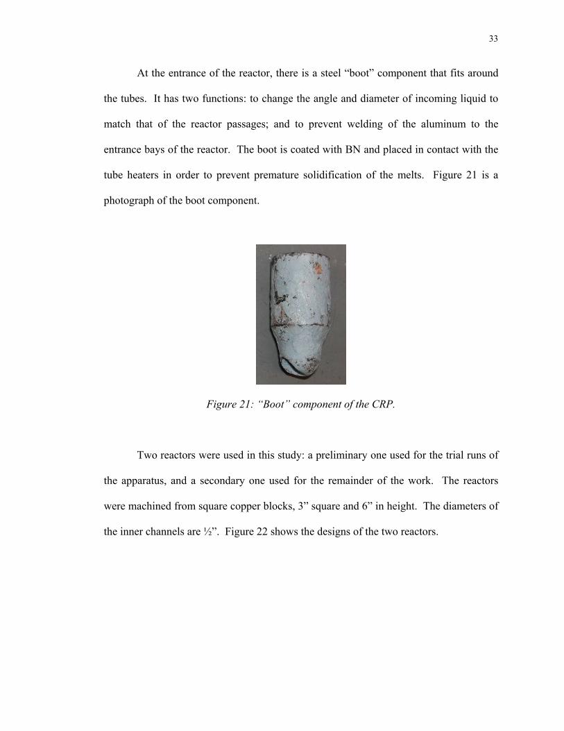
At the entrance of the reactor, there is a steel “boot” component that fits around
the tubes. It has two functions: to change the angle and diameter of incoming liquid to
match that of the reactor passages; and to prevent welding of the aluminum to the
entrance bays of the reactor. The boot is coated with BN and placed in contact with the
tube heaters in order to prevent premature solidification of the melts. Figure 21 is a
photograph of the boot component.
Figure 21: “Boot” component of the CRP.
Two reactors were used in this study: a preliminary one used for the trial runs of
the apparatus, and a secondary one used for the remainder of the work. The reactors
were machined from square copper blocks, 3” square and 6” in height. The diameters of
the inner channels are ½”. Figure 22 shows the designs of the two reactors.

34
Figure 22: Inner designs of the preliminary (left) and secondary (right) mixing reactors.
It was important to ensure that the preliminary reactor effectively mixed the melt
streams, and that convection forces were in place. Therefore a similitude experiment
was carried out in which two water streams containing different colored dyes were
mixed within the preliminary reactor. Plexiglas® was placed over the face of the reactor
and the experiment was recorded with a video camera. Based on this experiment, it was
determined that adequate mixing took place within the reactor. It was thus concluded
that molten aluminum flowing through the reactor experiences forced convection due to
interaction of the two liquids streams.
In the second reactor, angled paths were again used, but with a different, more
symmetric design. In order to verify that the second reactor provided forced convection,
another similitude experiment was carried out using the same procedure outlined above.
The experiment indeed showed this to be the case, so the design was kept as a constant
parameter in this study. In future work, this variable will be explored using mathematic
modeling to characterize and optimize the reactor’s mixing capability.

35
As seen in Figure 22, the copper block was split in half along the vertical
direction. The inner machining was done using a computer-guided end mill. Holes
were tapped in the two faces so that the block could be clamped together with hexagonal
screws. The inner faces of the reactor were coated with graphite spray to improve melt
flow. Four small thermocouple holes were also endmilled at various points of the
mixing channel in order to record the temperatures of the flowing melt streams at
various points of the process. Finally, two support arms were constructed to connect to
the top of the reactor, allowing for the reactor to be placed within a preheating furnace.
A photograph of this particular setup is shown below in Figure 23.
Figure 23: Setup of the third furnace when the reactor is preheated.
When the above configuration is not used, the reactor sits on two parallel
Unistrut® beams, set at an appropriate height to connect to the transport tubes. The
receiving crucible is placed as close to the reactor’s exit as possible to minimize
turbulence in the product slurry as it fills the receptacle.

36
There are three combinations of the above-described components used in the
experiments. The third mobile resistance furnace (of 6” inner diameter and 6” height)
can be used in two ways. In one configuration, the reactor is suspended within the
furnace and preheated so that its heat extraction capability is varied. The low solid
fraction slurry that exits the reactor is then deposited into a clay-graphite crucible and
cooled in air.
The second configuration allows for the receiving crucible to be placed within
the third furnace, where its temperature can be set before an experiment takes place.
This is the direct rheoconversion application of the CRP, because the product slurry that
exits the reactor is deposited into a heated receptacle. Therefore the slurry can be cooled
very slowly through its SSM temperature range, and small amounts can be removed and
quenched to observe the microstructure.
The third and final configuration does not employ the third furnace at all, but
converts the liquid to slurry using an unheated reactor. The slurry is then deposited into
a unheated receiving crucible, where it solidifies in air.
37
4.1.2 – Process Variables
Now that the liquid mixing device has been fully described, the variables that
were studied will be discussed. In any process there are two kinds of variables:
independent and dependent. The independent variables are those that can be changed by
applying different experimental conditions, whereas the dependent variables are dictated
by the imposed conditions. In this study, there are only two dependent variables: (a) the
microstructure of the samples obtained in any given experiment and (b) the temperature
of the low solid fraction slurry that exits the mixing reactor. If further processing were
done to the slurry, such as rheological measurements or mechanical testing of cast
samples, then these too would be dependent variables that could be correlated to the
imposed conditions of an experiment.
On the other hand, there are several independent variables that can be changed
due to the design of the CRP apparatus. The most important is the heat content in the
precursor melts. Since the two furnaces independently control each melt, this variable is
tightly controlled. Another independent variable is melt chemistry. Separate starting
vessels make available the option of using alloys of different compositions. For
example, one could mix a melt containing grain-refining additions with one containing
no grain refiners. Another example is to have a master alloy in one vessel and a pure
metal in the other, and mix them together to form a third alloy of a desired composition.
The heat extracting capability of the reactor is an independent variable, since the reactor
can be preheated prior to melt mixing. The degree of heat extraction corresponds to the
nucleation rate induced in the solidifying melt stream. The temperature of the receiving
crucible is also an independent variable, and can be varied to observe the effect of

38
cooling rate on the structural evolution in the collected slurry. Finally, when the
receiving crucible is preheated, the cooling rate of the slurry can be controlled by
varying the crucible temperature. Other sample collection methods to be described
shortly can also affect cooling rate, which directly impacts the microstructural evolution.
There are also a few independent variables that were not explored in this study.
The first is velocity of the melts as they flow into the reactor. Since the lengths of the
melt transport tubes (and the angles at which they are bent) were kept constant, velocity
was not varied. This variable warrants further attention, since it may affect the level of
forced convection in the reactor. Also, since only two reactor designs were used, the
forced convection due to the inner channel design was not changed appreciably. In
future studies, different reactor designs will be employed to address this important
parameter. Finally, in all experiments, the temperatures of the two precursor melts were
kept equal to influence uniform temperature fields within the reactor. When two
different alloy systems are used in the CRP, their temperature difference (due to
different liquidus points) becomes another potential variable.
4.2 - Experimental Plan
The layout of this section is as follows. First, the preliminary work carried out
will be discussed. The two subsequent sections address two important variables: the
alloys used in the CRP and method of slurry collection and analysis. Next, the
experiments carried out in the work will be described. The description of the
experiments is separated into five sections, corresponding to two thixocasting subsets
and three rheocasting subsets.
39
4.2.1 – Preliminary work
As mentioned previously, the impetus for this work came from a liquid mixing
experiment performed by Nasim Alem during her investigation into novel grain
refinement methods. The first task carried out was to reheat that sample into the semi-
solid temperature range and quench it in water. The purpose was to verify that the
equiaxed structure obtained in her experiment would evolve to a thixotropic structure
upon partial remelting. Subsequent to this, verification of the first liquid mixing
experiment was performed, using the same methods carried out by Alem.
Once the apparatus was constructed, there were several trial runs carried out.
Only the superheats of the melts were varied in these experiments, and they were kept to
within a few degrees of the liquidus temperature. The intent of these runs was to test the
equipment, determine if any modifications were needed, and ensure that the apparatus
consistently produced thixotropic structures.
4.2.2 – Alloys used
The three alloys used were A356.2 (with no grain refiners), A356.2 (with TiB2
grain refiners), and SiBloy®, which contains permanent grain refiners in the form of
AlB2 particles. Table 1 gives the chemical compositions and liquidus temperatures of
each of these alloys. Chemical compositions were obtained with a Spectromax®
spectrographic analysis machine. Liquidus temperatures were determined with the
derivative method on data collected in cooling experiments using calibrated
thermocouples.

40
Table 1: Chemical compositions (wt%) and liquidus temperatures (°C) of the alloys used.
TL
Si
Fe
Mn
Mg
Ti
Sr
V
B
Al
A356.2
(NGR) -
without GR
616.2 6.82 0.07 0 0.324 <0.002 <0.001 0.006 0.001 Bal.
A356.2 (GR)
– with GR 615.5 6.87 0.06 0 0.36 0.11 <0.001 0.008 0.0005 Bal.
SiBloy®
616.0
6.83 0.08 0.02 0.291 0.003 0 0.001 0.016 Bal.
The first stock of A356.2 alloy had a negligible Ti content, and thus was absent
of grain refinement. This alloy was used solely in the thixocasting experiments. A
second supply of A356.2 alloy had TiB2 (“TiBor”) grain refiners present. The third
alloy used, SiBloy®, is a permanently grain refined alloy containing AlB2 particles in the
molten state. SiBloy® was only used for one experiment in order to compare its grain
refinement to that of A356.2 with TiBor. The grain-refined alloys were used only in the
rheocasting experiments. A batch of A356.2 with no titanium was prepared for the final
experiment, in which slurry structures from grain-refined and non-grain-refined alloys
were compared.

41
4.2.3 – Slurry collection method
Two methods of slurry collection and analysis were followed. In the first
method, the slurry was solidified in air within a clay-graphite crucible, after which small
samples were reheated into the SSM range and quenched. This is termed the
thixocasting set, and its purpose was to verify exploratory findings, as well as to study
the microstructural evolution of the as-solidified samples upon partial remelting.
In the second method, the product slurry did not solidify to give a thixocast
sample, but rather simulated the “slurry-on-demand” method. In these experiments,
which comprise the rheocasting set, the slurry was collected and quenched into water at
various temperatures within the two-phase range of the alloy. Three distinct methods of
collecting the rheocast slurry were used in the rheocasting set of experiments. In the
first method, slurry was quenched immediately into water without entering a crucible.
In the second technique, a heated receiving crucible was employed from which small
amounts of the slurry were removed (scooped out) at various times and quenched in
water. In the third approach, the entire slurry crucible was quenched in water at a single
temperature in the two-phase field. By changing the temperature of the receiving
crucible, the cooling rates of the received slurry were varied. Figure 24 is a schematic
that illustrates the solidification paths induced in these two sets of experiments. Figure
25 is a flow chart that shows in detail the sample collection methods.

42
Figure 24: Schematic diagrams detailing the solidification paths undergone in the two experimental phases. Arrows indicate quenching of slurry.

43
Figure 25: Flow chart of the three sample collection methods.
4.2.4 – Thixocasting experiments: Variable thermal conditions
Heat transfer conditions in the reactor were affected but varying two parameters:
melt superheat and reactor temperature. In the first set of thixocasting experiments
(denoted “T1”), the superheats of the precursor melts were varied from 1-64°C in order
to gauge the heat extraction capability of the reactor. The reactor was kept at room
temperature. Table 2 lists these experiments. “TIN” refers to the temperature of each
melt prior to mixing.

44
Table 2: Experiments carried out in the “T1” series.
Expt. TIN (°C) Mass/melt (g) Alloy Treactor (°C) T1-1 617 300 A356.2 (NGR) 32 T1-2 625 300 A356.2 (NGR) 32 T1-3 640 300 A356.2 (NGR) 32 T1-4 660 300 A356.2 (NGR) 32 T1-5 680 300 A356.2 (NGR) 32
In the second set of thixocasting experiments (denoted “T2”), three superheats
and three reactor temperatures were chosen to observe the effects of different heat
transfer conditions on the resultant structures. The reactor was placed within the third
furnace, and four thermocouples were inserted into the thermocouple holes to monitor
its temperature. An increase in reactor temperature decreases the heat extraction rate of
the melts as they flow through it. Therefore the nucleation rate of the combined melts is
also decreased. The receiving crucible was at ambient temperature upon collection of
the slurry. A thermocouple placed in the exit channel recorded the slurry’s exit
temperature. Table 3 lists the experiments carried out with this configuration.
Table 3: Experiments carried out in the “T2” series.
Expt. TMIX (°C) Treactor (°C) Alloy Mass/melt (g)
T2-1 625 130 300 T2-2 625 315 A356.2 (NGR) 300 T2-3 625 500 300 T2-4 640 130 300 T2-5 640 315 A356.2 (NGR) 300 T2-6 640 500 300 T2-7 655 130 300 T2-8 655 315 A356.2 (NGR) 300

45
4.2.5 – Rheocasting experiments: Immediately quenched slurry
Two experiments were carried out to observe the structure of the low solid
fraction slurry immediately upon exiting the reactor. A large reservoir of cold water was
used as a receptacle. This resulted in a very high cooling rate in the collected slurry.
The first of these experiments was done at a temperature of 625°C, and the second at
640°C. All other conditions were identical to those in experiment T1-2 (see Table 3).
These experiments are denoted “R1.”
4.2.6 – Rheocasting experiments: Various slurry collection temperatures
The next stage in the project involved the direct collection of semi-solid slurry.
Using the third furnace, the receiving crucible was preheated to various temperatures.
After slurry collection, small amounts were scooped out from the receptacle and
quenched in water. The reactor was kept at ambient temperature for each of these
experiments. The first phase of these experiments, denoted “R2,” is listed in Table 4.
Table 4: Experiments carried out in the “R2” experiments.
Expt. TMIX (°C) Tcruc (°C) Alloy Samples taken at (°C) R2-1 640 585 A356.2 (GR) 597, 590, 585, 575, RT R2-2 655 585 A356.2 (GR) 605, 597, 590, 585, 575, RT R2-3 625 585 A356.2 (GR) 610, 605, 597, 590, 585, 575, RTR2-4 670 585 A356.2 (GR) 610, 597, 590, 585, 575, RT R2-5 625 450 A356.2 (GR) 610, 600, 590, RT R2-6 625 450 SiBloy® 610, 600, 590, 580, RT R2-7 625 450 A356.2 (NGR) 600, 590, 580, RT
.

46
In the first five of the above experiments, the A356.2 (GR) alloy described in
Table 1 was used. The higher level of titanium in this alloy resulted in grain refinement,
whereas the alloy used in all previous experiments had negligible titanium. Experiments
R2-5 and R2-6 sought to compare the structures obtained with different grain refining
agents. R2-5 (A356.2 with 0.11wt%Ti) had TiB2 particles present in the melt, whereas
R2-6 (SiBloy®) had AlB2 inoculants. Finally, R2-7 employed A356.2 with no grain
refiners, in order to compare the results to those obtained with inoculants present. Since
two different crucible temperatures (585°C and 450°C) were used in the experiments,
different cooling rates of the slurry through the two-phase field resulted. In all
experiments the mass of each charge was approximately 300g.
4.2.7 – Rheocasting experiments: Single slurry collection temperature
In an alternative approach, different preheat temperatures in the receiving
crucible were used to attain different cooling rates of the product slurry through the two-
phase region. Furthermore, the entire slurry crucible was quenched in a large volume of
water, rather than removing small amounts at iterated times. This gave a more accurate
sense of the temperature of the sample upon quenching. In the R2 experiments, the
thermocouple was not always in the same area as the slurry samples that were removed
and quenched, so there was a slight uncertainty in temperature. These experiments,
denoted “R3,” are summarized in Table 5.

47
Table 5: Experiments carried out in the “R3” series.
Expt. TMIX (°C) Tcrucible (°C) Alloy Mass/melt (g) Sample(s) taken at
(°C) R3-1 625 100 A356.2 (GR) 300 588 R3-2 625 200 A356.2 (GR) 300 585 R3-3 620 200 A356.2 (GR) 300 585 R3-4* 625 500 A356.2 (GR) 300 585 R3-5 625 500 A356.2 (GR) 300 585
As seen in Table 5, the main variable was the receiving crucible temperature,
which led to different cooling rates of the slurry through the two-phase field. R3-4 is
marked because only one melt was used in order to observe the theoretical effect of less
convection (due to less liquid mixing) on the resultant structures.
4.3 - Experimental Procedures
This section outlines the steps taken in performing the liquid mixing
experiments. The procedure for verification of Alem’s experiment was as follows.
Two separate crucibles were heated in resistance box furnaces, each containing about 1
lb. of alloy. One crucible contained A356.2 (no grain refiners) and the other contained
SiBloy®. After melting, the crucibles were removed from the furnaces and allowed to
cool to 617°C and 622°C, respectively. At this point, the crucible containing SiBloy®
was poured into the A356.2-containing crucible. A cold graphite rod, 1” in diameter,
was used to stir the melt mixture. Stirring with this material resulted in a rapid cooling
rate of through the liquidus temperature, and forced convection to disperse the nuclei.
The final melt was then allowed to solidify in air. A small sample (about 5g) of this
alloy was reheated to 585°C, held there for several minutes, and quenched in water to

48
retain the semi-solid microstructure. Metallographic analysis of both the “as-solidified”
and reheated samples was carried out.
The procedure for using the liquid mixing apparatus is as follows. First, the
reactor is prepared by spraying a coating of graphite onto the inner surface. When used
at ambient temperature, the reactor is placed onto two Unistrut® beams, after which the
melt transport tubes are put into place. When preheated, the positions of the beams are
modified to hold the preheating furnace. The reactor is placed within the furnace using
two support arms, as was shown in Figure 23, and its temperature is monitored with four
K-type thermocouples.
The crucible assembly is not removed from the apparatus unless maintenance is
required, so the next step is to connect the melt transport tubes from the reactor entrance
to the crucible spouts. The coiled heating elements are placed around the tubes before
this step. Insulation is wrapped around the tubes and placed into the bottom holes of the
melting furnace. The control thermocouple for the transport tubes is inserted into the
insulation layer so that it touches the surface of the tube. The receiving crucible
contains a thermocouple with a stainless steel protection tube to record the temperature
of the slurry upon exiting the reactor.
In the thixocasting experiments, the receiving crucible sits just below the exit of
the reactor. In the R1 experiments, a large volume of water is used rather than a crucible
to immediately quench the slurry. For the R2 and R3 experiments, the crucible is
preheated within the third furnace. A preheated graphite “slurry-scooping” utensil is
employed to take out small amounts of slurry and quench them in water.

49
The next step is to place the alloy charges, about 300g each, into the melting
crucibles. Thermocouples are inserted into these crucibles to monitor and record the
temperatures of the separate melts, and insulating material is placed atop the furnaces.
Melting of the charges occurs after about a half hour, with a setpoint of 750°C-800°C.
The temperatures of the transport tubes are set to 10°C above the precursor melts’
temperatures. Temperature data is recorded using a data acquisition system and
DasyLab® software. After the melts reach the desired temperatures, a toggle switch is
thrown, which activates the solenoids and unplugs the melting crucibles’ exit holes.
Metal flow through the reactor is completed in about 3-4 seconds.
When reheating samples in the thixocasting experiments, a small hole is drilled
into the slug to hold the thermocouple. The sample is placed within the furnace using a
suspension mechanism that hangs from the overhead beam. The sample is partially
remelted at 585°C for about ten minutes, after which it is quenched into a bucket of
water located below the furnace.
Metallography of the samples was carried out as follows. Small pieces of the
samples were taken from various points in the solidified alloy (bottom, middle, and top
positions), and were hot-mounted in bakelite. These were then ground from 320grit up
to 4000grit silicon carbide paper. Initial polishing employed a 1µm followed by a
0.3µm alumina suspension, and final polishing was carried out using a 0.04µm colloidal
silica suspension. Samples were etched with Keller’s reagent, and optical microscopy
was done with MicroGOP software. Data for shape factor and particle size were
obtained with AnalySIS software.

50
5. Results & Discussion
In this section the results from selected liquid mixing experiments are presented.
The results are discussed in terms of their microstructural features (including image
analysis data), and correlated to the conditions imposed in each experiment. First,
results from the thixocasting set of experiments are presented, followed by the
rheocasting set. Quantitative correlation between cooling rate through the SSM range
and final particle size is then given. Finally, the mechanisms governing SSM structure
formation in this process are summarized.
5.1 – Thixocasting route
In the first set of experiments, a thixocasting approach was followed. Here, “as-
solidified” samples were reheated to the semi-solid state and quenched. Two variables
were investigated in these experiments: superheat of the melts prior to mixing (“T1”
experiments) and temperature of the reactor (“T2” experiments).
5.1.1 – Variable: Superheat
Results from three superheat-variable experiments are presented in this section.
Table 6 gives the conditions and thermal results of the experiments.

51
Table 6: Conditions and thermal results for the T1 (superheat-variable) experiments.
Expt. Tin
[°C]
Tin-TL
(Superheat)
[°C]
Tout (approx.)
[°C]
Treactor
[°C]
dT/dt (in
crucible)[°C/sec]
Sampling
method
T1-2 625 9 611-613 30 -1.10 Air cool;
reheat
T1-3 640 24 613-615 30 -1.08 Air cool;
reheat
T1-4 660 44 615-617 30 -0.85 Air cool;
reheat
Figures 26-28 exhibit the representative micrographs from the experiments
described above. To the left are the as-solidified structures; at the right are the structures
obtained after reheating to 585°C and holding for 10 minutes, followed by immediately
quenching into water.

52
Figure 26: (a) As-solidified and (b) reheated microstructures from experiment T1-2.
Residence time of reheated slug in SSM range: 38 minutes.
Figure 27: (a) As-solidified and (b) reheated microstructures from experiment T1-3.
Residence time of reheated slug in SSM range: 25 minutes.
Figure 28: (a) As-solidified and (b) reheated microstructures from experiment T1-4.
Residence time of reheated slug in SSM range: 18 minutes.

53
The above three Figures show the effect of raising the superheat of the precursor
melts on the resultant microstructures. Each of the above microstructures is highly
refined compared to typical as-received ingots. The reheated samples show globular α-
Al particles distributed in a liquid matrix, with very little entrapped liquid. It is clear
that the entrapped liquid in these samples results from coarsening of irregular (i.e. semi-
dendritic) particles during reheating. In Figures 26-28 most of the particles have a
spherical morphology, but a small portion of them is irregular in shape. Irregularly
shaped particles are seen in all results from this study, and their origins are likely related
to dendritic growth within the reactor. Although to a limited extent, small dendrites
inevitably grow in some parts of the flowing liquid; collisions of these particles may
account for the observed shapes. Also evident in the micrographs is an appreciable level
of particle agglomeration, which is common characteristic of the structures obtained
with the current reactor. It is believed this is a combination of (a) the collisions
undergone as the melts flow through the reactor, and (b) grain coalescence during
reheating.
Table 7: Image analysis results for the T1 experiments.
Experiment
Avg. Particle
Diameter, As-
solidified (µm)
Avg. Particle
Diameter,
reheated (µm)
Avg. Shape
Factor,
reheated
Number of
particles
analyzed
T1-2 65.2 92.1 0.86 547
T1-3 76.7 96.8 0.88 409
T1-4 90.1 101.2 0.87 378

54
Table 7 summarizes the image analysis results for the micrographs shown.
Increasing the superheat clearly results in larger particle size in both the as-solidified
and reheated samples. Shape factor data show that increasing superheat does not affect
the morphologies of the analyzed particles. Shape factor was determined from the
relationship,
Shape Factor = (4π∗Area)/ Perimeter2
A shape factor value of one corresponds to a perfectly spherical particle, whereas
values close to zero indicate dendrites or very irregularly shaped particles. In the
reheated samples (and slurry samples shown later), only the more spherical particles
were analyzed in order to avoid confusion arising from numerical contributions of
irregular particles. This was achieved by defining a classification scheme in the analysis
program in which particles with very low shape factor values were excluded. Finally,
the number of particles analyzed gives an indirect quantification of the degree of particle
irregularity in the samples. Although the micrographs chosen may not portray the exact
fraction of irregular particles in the entire sample, it is noteworthy that this value
decreases for increasing superheat.
In Figure 26, the most uniform as-solidified structure is observed, with the
highest level of grain refinement and non-dendritic morphology. Figure 27 exhibits a
similar microstructure, but with a larger average particle diameter. There is still a high
amount of non-dendritic particles, but a well-globularized SSM structure is obtained
upon reheating. Figure 28 has the largest particle size, and shows the highest number of

55
irregular particles. Even at this high superheat, the particles are for the most part non-
dendritic. Despite the higher fraction of irregular particles, the reheated structure
indicates a predominantly globular morphology. This may be due to the long residence
times of the reheated samples in the SSM range (due to the long time is took for the
sample to reach 585°C). Longer residence times lead to coarsening of the particles;
therefore initially irregular particles may become more spherical due to the driving force
for these particles to reduce surface area. This also explains why for each experiment
the particles in the reheated samples are larger than in the as-solidified ones.
It is concluded from this set of experiments that globular structures can be
obtained by mixing alloy melts having relatively high superheats. This indicates that the
reactor is able to extract very large amounts of heat in a small amount of time.
Therefore it is not necessary to have a precursor liquid very close to the liquidus
temperature in order to obtain thixotropic structures with this process. Finally, in both
the as-solidified and reheated samples, there is a clear trend of (a) increasing particle
size for increasing superheat and (b) increasing level of particle irregularity (or tendency
to grow dendritically to small degrees) for increasing superheat.
5.1.2 – Variable: Reactor temperature
Table 8 shows the conditions and thermal results for the variable reactor
temperature experiments. For T2-4 through T2-6, the superheat was kept the same
while the temperature of the reactor was varied. T2-8 had the lowest heat extraction
conditions, thus the temperature of the exiting slurry was above the liquidus.

56
Table 8: Conditions and thermal results for selected T2 (variable reactor temperature) experiments.
Expt. Tin [°C] Tin-TL
[°C]
Treactor
[°C]
Tout
(approx.)
[°C]
dT/dt (in
crucible)[°C/sec]
Collection
method
T2-4 640 24 130 612.5 -0.81 Air cool; reheat
to 585°C
T2-5 640 24 315 614.3 -0.84 Air cool; reheat
to 585°C
T2-6 640 24 500 616.4 -0.74 Air cool; reheat
to 585°C
T2-8 655 39 315 618.1 -0.75 Air cool; reheat
to 585°C
The temperature of the reactor was increased in order to decrease its heat
extraction capability. The purpose was to vary the processing conditions to give a wide
range of particle morphologies, as well as to establish relationships between the
variables and the resultant microstructures. In doing so, the limits of the reactor’s heat
extraction capability were gauged. Figures 29-32 show the results from the experiments
listed above. Again, the as-solidified structures are on the left, with the reheated
structures on the right.

57
Figure 29: (a) As-solidified and (b) reheated microstructures from experiment T2-4.
Residence time of reheated slug in SSM range: 24 minutes.
Figure 30: (a) As-solidified and (b) reheated microstructures from experiment T2-5.
Residence time of reheated slug in SSM range: 25 minutes.
Figure 31: (a) As-solidified and (b) reheated microstructures from experiment T2-6.
Residence time of reheated slug in SSM range: 16 minutes.

58
Figure 32: (a) As-solidified and (b) reheated microstructures from experiment T2-8.
Residence time of reheated slug in SSM range: 2 minutes .
The particle size in the as-solidified samples increases slightly from T2-4 to T2-5
due to the lower heat transfer within the reactor. In the reheated samples, it is observed
that both experimental conditions lead to highly globular structures of similar particle
size. Figure 30(b) shows roughly the same number of irregular particles than in Figure
29(b), and the majority of both structures is globular. In these two experiments, the
product slurry exited the reactor at a temperature just below the liquidus temperature of
the alloy, resulting in a very low solid fraction, highly fluid slurry. Previous work at
MIT with the SSR process [18] suggested that as long as this condition is met (i.e.
forming a very low solid fraction rather than cooling the alloy several degrees below the
liquidus), then non-dendritic structures result. In other words, all of the particles seen in
any given sample must form at or just below the liquidus temperature; therefore it is
only necessary to cool the liquid to a one or two degrees below this temperature. The
above results show that this reasoning pertains to the CRP as well.

59
Table 9: Image analysis results for the T2 experiments.
Experiment
Avg. Particle
Diameter, As-
solidified (µm)
Avg. Particle
Diameter,
reheated (µm)
Avg. Shape
Factor,
reheated
Number of
particles
analyzed
T2-4 67.6 96.8 0.89 393
T2-5 76.8 98.5 0.90 387
T2-6 105.3 116.7 0.71 235
Table 9 lists the image analysis results for the T2 experiments. In the above
Table, and throughout this section, the term “average” in relation to shape factor values
refers to the mean value taken from the entire data set of all particles analyzed by the
classification scheme. It is clear from the micrographs that particle shape irregularity
reaches a maximum when the reactor temperature is highest. Numerically, shape factor
values are about the same in the first two runs, but change noticeably in experiment T2-
6. Also, the number of particles analyzed drops in T2-6, which suggests that more
irregular particles were excluded by the classification scheme. Moreover, in T2-6 the
presence of non-spherical particles in both the as-solidified and reheated samples is
more evident than in the previous experiments. The exiting slurry was just above the
liquidus temperature of the alloy, as shown in Table 8, therefore the thermal conditions
of the reactor led to a lower level of nucleation. The decrease in nucleation rate led to a
larger particle size in T2-6, since grain growth was promoted by the presence of fewer
particles. On reheating, a significant amount of liquid was entrapped by the coarsening
particles, as seen in Figure 31.

60
Figure 32 reinforces the reasoning presented above concerning the requirement
of a small solid fraction of the slurry upon exit. The exit temperature was 618°C, and
these microstructures show the highest degree of dendritic growth. This is because the
majority of nuclei formed within the receiving crucible rather than the reactor; therefore
there was a lower cooling rate through the alloy’s liquidus temperature. Upon reheating
and quenching, the dendrites in the as-solidified structure coarsened, but did not
approach the level of sphericity observed in the previous reheated samples.
It is concluded from these experiments that the goal of forming a distinct range
of particle morphologies was met by heating the reactor to various temperatures.
Particle size increased and shape factor decreased when the reactor was hottest
(providing less heat extraction), which suggests less effective heat extraction in the
reactor. A higher reactor temperature led to more dendritic morphologies, whereas
lower reactor temperatures produced spherical, thixotropic slurry structures. The extent
to which the metal is cooled below its liquidus temperature dictates how globular the
overall structure becomes.
5.2 – Rheocasting route
In the rheocasting set of experiments, a heated receiving crucible allowed for the
direct sampling of semi-solid slurry produced by the CRP. Three different methods of
slurry collection were followed. First, slurry was immediately quenched into water
without the presence of a receiving crucible; second, several samples of slurry were
collected and quenched at various points while cooled slowly through the two-phase

61
range; and finally, the entire slurry-containing receiving crucible was quenched at one
temperature in the semi-solid temperature range.
5.2.1 – Immediately quenched slurry
In these experiments, the slurry went from the reactor’s exit directly into a large
volume of water. Therefore the sample was immediately quenched and the
microstructure was frozen in place. In the experiment presented below, the temperature
of the precursor melts was 625°C, giving a superheat of about 9°C. The reactor was at
room temperature, as was the water used for quenching. The cooling rate and
temperature of the slurry upon exit was not measured due to the experimental setup, but
the conditions are the same as those in experiment T2-2. Figure 33 shows two
micrographs from this experiment.
Figure 33: Microstructures from experiment R1-1. The sample was immediately
quenched in water upon exit from the reactor.

62
Table 10: Image analysis results for experiment R1-1.
Expt. Avg. Particle
Diameter (µm)
Maximum
Particle Diameter
(µm)
Minimum
Particle Diameter
(µm)
Avg. Shape Factor
R1-1 19.7 34 13.6 0.79
The microstructures shown above are much different than those seen in the
thixocasting experiments. The primary particles are a great deal smaller, which is to be
expected since there is very little time allowed for growth. The fine structure of eutectic
phase shows that the cooling rate during quenching was very fast. The smallest particles
seen above are less than 15µm in diameter, and the larger ones are less than 40µm, as
shown in Table 10. Also, there are many more irregularly shaped particles (as well as
some rosettes) observed here than in previous experiments. Two major factors
contribute to these morphologies. First, the higher heat transfer undergone within the
water bath results in very little particle growth after nucleation. Secondly, the additional
convection that is typically experienced by the slurry as it fills the receiving crucible is
absent here. Since the slurry is highly fluid on exit, convection from crucible filling
may contribute to breaking up of dendrites and spheroidization of the irregular particles.
It should be noted that the micrograph containing the dendrites is not representative of
the entire sample; rather, they only formed in a particular section of the quenched
sample. It is also possible that the dendrites do not form in the reactor, but instead
nucleate as the liquid phase is exposed to air in the short distance between the reactor
and the water.

63
When low solid fraction semi-solid slurry is quenched into water, it is expected
that large amounts of eutectic be quenched from the liquid phase; therefore the density
of the primary particles should be low. However the above Figures dispute this
expectation, since a large number of particles is present in the slurry as it exits the
reactor. The solid fraction observed in the micrographs, which are from a slurry initially
at about 610°C, are much higher than one would expect. This evidence suggests that
additional nuclei form during the water quench, and then grow to a very small degree.
These nuclei most likely form on particles that were present in the slurry as it exited the
reactor.
It is concluded from these experiments that very fine-grained structures are
obtained when the slurry is immediately quenched and not collected in a crucible. This
finding directly shows that there is a very high density of nuclei in the exiting slurry,
which further indicates that copious nucleation takes place in the reactor. Also, the
convection/turbulence undergone by the slurry as it fills a receiving crucible may play a
role in the mechanisms leading to SSM structure formation in the CRP.
5.2.2 - Slurry quenched at various SSM temperatures
In these experiments, slurry samples were quenched at various temperatures
within the SSM range. In the first experiment, a very slow cooling rate though the SSM
range occurred due to a high receiving crucible temperature. In the other three
experiments, the cooling rate was higher, and was kept nearly constant. In these higher
cooling rate experiments, the variable of grain refinement additions was also

64
investigated. Table 11 lists the conditions and thermal results of the experiments to be
presented. For each of these experiments, the reactor was kept at room temperature.
Table 11: Conditions and thermal results for the R2 (slurry quenching I)
experiments.
Expt.
Tin
[°C]
Tout
[°C]
Tcrucible
[°C]
dT/dt (in
crucible)
[°C/sec]
Total
residence
time in
SSM range
(min)
Slurry temp.
[°C]
Alloy
R2-2 655 616 585 -0.07 17
605, 597, 590,
585, 575, As-
solidified
A356.2 w/ TiB2
R2-5 625 614 450 -0.22 2.8
610, 600, 590,
As-solidified
A356.2 w/ TiB2
R2-6 625 614 450 -0.23 2.8
610, 600, 590,
580, As-
solidified
*SiBloy® w/ AlB2 GR
R2-7 625 614 450 -0.18 3.6 600, 590, 580,
As-solidified
Non-grain-
refined
A356.2

65
(a) Slow cooling rate through SSM range
Figure 34 is a collection of micrographs from the first experiment listed in Table
11.
605°C; t=4.2min 597°C; t=9.6min
590°C; t=14.5min As-solidified
Figure 34: Microstructural results from experiment R2-2; slurry samples obtained at the specified temperatures and times after slurry collection.
The structures are far superior to those obtained with the thixocasting method.
Particle sizes are much smaller using this technique, and size distributions do not vary to
an appreciable extent. The presence of dendrites in isolated regions of the samples is an
interesting feature, but the majority of these structures are of a globular nature. These

66
dendrites probably resulted from small volumes of liquid that were deposited into the
receptacle just above the liquidus temperature. The presence of even more developed
dendrites, as well as several other interesting microstructural features observed
throughout the study, is documented in Appendix A.
The above results give direct evidence that the liquid mixing method leads to
highly globular semi-solid slurries of fine particle size. Upon entry of these slurries into
the heated receptacle, a relatively large amount of time was spent in the SSM range due
to the slow cooling rate resulting from a high receptacle temperature. Nonetheless,
whatever amount of growth occurred did not result in a significant increase in particle
size. The solid fractions suggested by the above Figures, however, are in contradiction
with the theoretical values. That is, one would expect to see more liquid phase at a
temperature of 605°C. This may be due to the method that the samples were collected
and quenched. The sample removal procedure may have resulted in segregation of the
solid particles from the liquid phase of the slurry. Also, there may have been slight
temperature variations between the location of the thermocouple and the region where
slurry was removed (a distance of about 2 inches). Table 12 summarizes the image
analysis results for these samples.

67
Table 12: Image analysis results for experiment R2-2.
Slurry temperature
(°C)
Avg. Particle
Diameter (µm)
Avg. Shape
Factor
Number of
particles
analyzed
605
68.8 0.83 745
597 84.2 0.82 377
590 85.7 0.87 459
As-solidified 103.2 - 87
It is concluded from these results that by using a heated crucible and collecting
slurry during its residence time in the SSM range, even better refined thixotropic
structures are observed. The particle sizes are much smaller when compared to the
reheated structures of the thixocasting experiments. As seen in Table 12, particle size
gradually increases as the slurry is solidified. Average shape factor data do not vary
appreciably.
(b) Higher cooling rate with variable grain refinement
Figures 35-37 compare the results from experiments R2-5, R2-6, and R2-7. In
R2-5, A356.2 (with TiB2) was used, whereas SiBloy® was used in R2-6. In R2-7, non-
grain-refined A356.2 alloy was used. The purpose of these experiments was twofold:
first, to compare the presence of two different kinds of grain refiners to the non-grain-
refiner-containing A356.2 alloy; and secondly, to study the effect of a higher cooling
rate through the semi-solid temperature range.

68
Figure 35: Slurries obtained using grain refined A356.2 (above left), SiBloy® (above
right), and non-grain refined A356.2 (bottom). Samples quenched at 600°C (1.8min and 2.0min after collection, respectively).

69
Figure 36: Slurries obtained using grain refined A356.2 (above left), SiBloy® (above
right), and non-grain refined A356.2 (bottom). Samples quenched at 590°C (2.3min and 2.8min after collection, respectively).

70
Figure 37: Slurries obtained using grain refined A356.2 (above left), SiBloy® (above right), and non-grain refined A356.2 (bottom). As-solidified structures.
The above three Figures show that the presence of grain refiners in an alloy
processed with the CRP only modifies the resultant structures to a small degree. The
two types of grain refiners used both lead to a similar particle size. The Figures also
clearly indicate that when a non-grain refined alloy is used, the average particle size
becomes slightly coarser; however, they still have highly refined structures in
comparison to most commercial SSM processes. It should be noted that the cooling rate
of the slurry after exiting the reactor in experiment R2-7 was slightly lower than in
experiments R2-5 and R2-6, which may have also contributed to this observed trend.
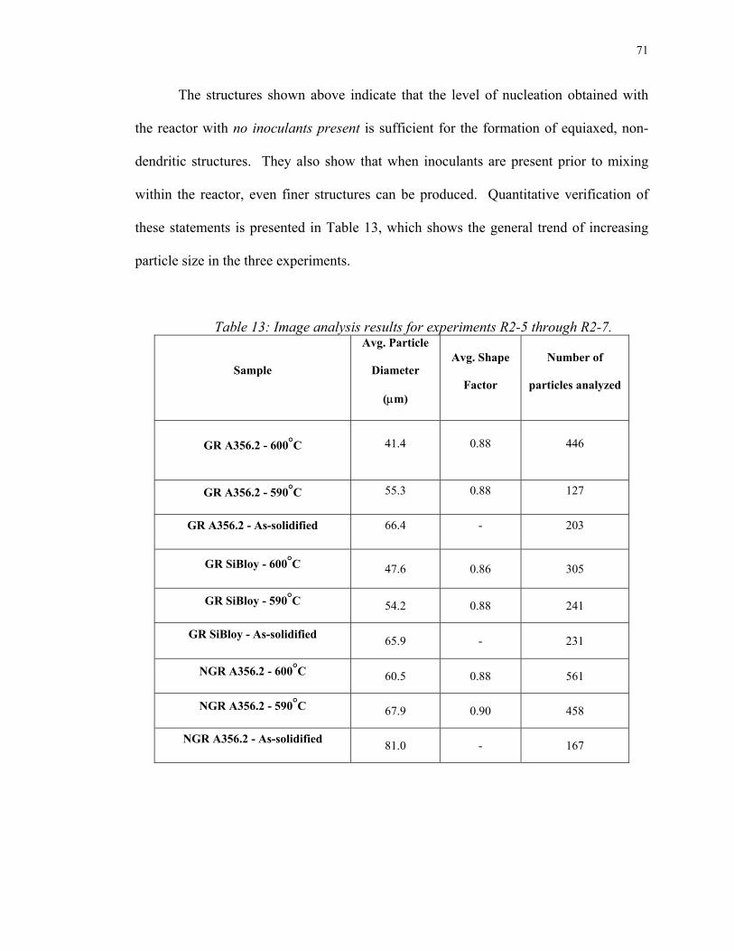
71
The structures shown above indicate that the level of nucleation obtained with
the reactor with no inoculants present is sufficient for the formation of equiaxed, non-
dendritic structures. They also show that when inoculants are present prior to mixing
within the reactor, even finer structures can be produced. Quantitative verification of
these statements is presented in Table 13, which shows the general trend of increasing
particle size in the three experiments.
Table 13: Image analysis results for experiments R2-5 through R2-7.
Sample
Avg. Particle
Diameter
(µm)
Avg. Shape
Factor
Number of
particles analyzed
GR A356.2 - 600°C
41.4 0.88 446
GR A356.2 - 590°C
55.3 0.88 127
GR A356.2 - As-solidified
66.4 - 203
GR SiBloy - 600°C 47.6 0.86 305
GR SiBloy - 590°C 54.2 0.88 241
GR SiBloy - As-solidified 65.9 - 231
NGR A356.2 - 600°C 60.5 0.88 561
NGR A356.2 - 590°C 67.9 0.90 458
NGR A356.2 - As-solidified 81.0 - 167

72
When comparing the above results to those shown in Table 12, it becomes clear
that the increased cooling rate led to a much finer particle size than in experiment R2-2.
Values for shape factor are about the same in all four runs. Figure 38 shows two
additional microstructures from experiment SQ9. This sample was quenched at 610°C,
corresponding to a low solid fraction.
Figure 38: R2-5 microstructures at 50X (left) and 200X (right). Sample quenched at
610°C (50 seconds after collection).
The above Figure shows that more nucleation events occur during the slurry
quenching technique. Image analysis results of these micrographs are shown below in
Table 14. The very small particles nucleated as the scooping utensil (thimble) was used
to transfer the sample from the crucible to the water. These nucleation events were
likely facilitated by the presence of TiB2 inoculants in the liquid phase of the slurry.
Therefore, if this additional nucleation event had not occurred, then the structures would
be comprised of the larger particles seen above, combined with quenched eutectic in the
regions where the smaller particles are observed. This structure would better reflect the
low solid fraction of the slurry at this temperature. The higher magnification

73
micrograph to the right shows that these secondary α-Al particles nucleate on the
previously formed particles.
Table 14: Image analysis results for the micrographs shown in Figure 38.
Sample Avg. Particle Diameter (µm)
Avg. Shape
Factor
Number of particles
analyzed
R2-5 - 610°C
Large particles (primary
nucleation event): 36.1
Small particles (secondary
nucleation event): 10.5
0.85 150
It is concluded from these experiments that a higher cooling rate through the
two-phase range leads to more refined SSM structures. Also, it is clear that the presence
of grain refiners in the alloys used does not significantly affect the particle size and
shape of the structures; that is, nucleation rate is not enhanced to an appreciable extent
when inoculants are present. The level of equiaxed, non-dendritic growth observed in
non-grain-refined A356.2 is high enough to conclude that the reactor design is the major
contributor to the observed structures.
5.2.3 - Slurry quenched at a single SSM temperature
In these experiments, the entire slurry-containing crucible was quenched into
water at a single temperature in the SSM range. The volume of slurry quenched here is
much larger than the volumes of “slugs” reheated in the thixocasting set. Two variables
were explored in these experiments. First, the effect of a higher cooling rate than the
ones in the R2 experiments was investigated. Secondly, instead of using two separate

74
melts, in experiment R3-4 only one melt was put through the CRP, in order to compare
forced convection levels. Table 15 lists the conditions and thermal results for the “R3”
experiments.
Table 15: Conditions and thermal results for selected R3 (slurry quenching II) experiments.
Expt.
Tin [°C]
Tout [°C]
Tcrucible [°C]
dT/dt
(in
crucible)
[°C/sec]
Total
residence
time in
SSM range
(min)
Slurry
temp.
[°C]
Comment
R3-1 625 613 100 -0.70 0.5 588
A356.2 w/
GR
R3-4 625 614 500 -0.24 1.5 586
One A356.2
melt (w/
GR)
R3-5 625 614 500 -0.14 3.5 586
Two A356.2
melts (w/
GR)

75
(a) High cooling rate through SSM range
Among the rheocasting experiments, experiment R3-1 underwent the highest
cooling rate through the SSM range; thus its residence time within the two-phase field
was the lowest. This explains the small particle size observed below in Figure 39.
Figure 39: Microstructures from experiment R3-1; 50X (left), 100X (right).
Figure 39 shows the most refined microstructure obtained in this study, with
primary particles in the range of 30-50µm in diameter. The majority of the particles
have a spherical shape. This is an important result because it shows that when a suitable
receptacle temperature is chosen, the cooling rate through the two-phase field can be
optimized, thus limiting grain growth and forming better SSM structures.

76
(b) One melt vs. two melts
Experiments R3-4 and R3-5 were carried out in order to see the effect of using
only one melt rather than two in the CRP. All other experimental conditions were
similar. Figures 40 and 41 show these results.
Figure 40: Microstructures from experiment R3-4; 25X (left), 50X (right).
Figure 41: Microstructures from experiment R3-5; 25X (left), 50X (right).
Although the processing conditions for R3-4 and R3-5 were similar, the cooling
rates (and hence residence times in the SSM range) were not the same, as noted in Table
15. This explains the slightly larger overall particle size in the Figure 40 micrographs,
since this sample was within the SSM range for about 2 minutes longer than in R3-5.
Also, as mentioned in Table 15, the temperature of the slurries shown above is 586°C,
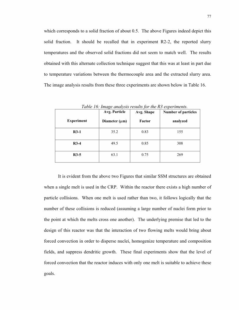
77
which corresponds to a solid fraction of about 0.5. The above Figures indeed depict this
solid fraction. It should be recalled that in experiment R2-2, the reported slurry
temperatures and the observed solid fractions did not seem to match well. The results
obtained with this alternate collection technique suggest that this was at least in part due
to temperature variations between the thermocouple area and the extracted slurry area.
The image analysis results from these three experiments are shown below in Table 16.
Table 16: Image analysis results for the R3 experiments.
Experiment
Avg. Particle
Diameter (µm)
Avg. Shape
Factor
Number of particles
analyzed
R3-1 35.2 0.83 155
R3-4 49.5 0.85 308
R3-5 63.1 0.75 269
It is evident from the above two Figures that similar SSM structures are obtained
when a single melt is used in the CRP. Within the reactor there exists a high number of
particle collisions. When one melt is used rather than two, it follows logically that the
number of these collisions is reduced (assuming a large number of nuclei form prior to
the point at which the melts cross one another). The underlying premise that led to the
design of this reactor was that the interaction of two flowing melts would bring about
forced convection in order to disperse nuclei, homogenize temperature and composition
fields, and suppress dendritic growth. These final experiments show that the level of
forced convection that the reactor induces with only one melt is suitable to achieve these
goals.

78
It is concluded from these experiments that the third rheocasting approach,
wherein the entire crucible’s contents were quenched, led to globular slurry structures of
even finer size. Using a higher cooling rate, particle size was minimized. The use of
one melt rather than two in the CRP does not noticeably affect the structures, although
there should theoretically be less forced convection. This suggests that the level of
forced convection in the reactor using one melt is sufficient for the formation of non-
dendritic slurries.
5.3 – Cooling rate vs. particle size
Several image analysis results have been presented in this section, and it is
appropriate to compare these numerical data to the cooling rates experienced by the
slurries through the two-phase field. Intuitively, slower cooling rates through the SSM
temperature range should result in structures having larger particle diameters; the
opposite should hold true for higher cooling rates. Figures 42 and 43 show the data
from selected rheocasting experiments.

79
dT/dt vs. Particle Size - As-solidified structures
0
20
40
60
80
100
120
-1.5 -1 -0.5 0 0.5 1 1.5 2 2.5
Log (dT/dt) [°C/sec]
Parti
cle
size
[ µm
]0.07, 103.3
0.22, 66.4
0.23, 65.9
200, 19.7
Figure 42: Particle size as a function of cooling rate of the slurry after exiting the
reactor. As-solidified structures.
dT/dt vs. Particle Size - SSM structures @ 590°C
0
10
20
30
40
50
60
70
80
90
0 0.1 0.2 0.3 0.4 0.5 0.6 0.7 0.8
dT/dt [°C/sec]
Parti
cle
Size
[ µm
]
0.07, 85.7
0.23, 54.20.22, 55.3
0.14, 63.1
0.24, 49.50.7, 35.2
0.18, 67.9
Figure 43: Particle size as a function of cooling rate of the slurry after exiting the
reactor. Slurry structures at 590°C. .

80
The above Figures show that higher cooling rates indeed lead to finer particle
size in the rheocasting experiments. The results imply that in the rheocasting approach,
it is straightforward to determine an optimum cooling rate to yield highly refined and
globular structures in the processed slurry. Such an optimum cooling rate, however,
while leading to fine particle sizes, must be applied uniformly throughout the bulk of
any given sized slurry bath. The data also suggest that in the CRP apparatus, the solid
fraction of the processed slurry can be quickly adjusted prior to subsequent forming.
From an industrial standpoint, this is highly desirable because uniform slurry structures,
which directly impact the uniformity of thixotropic flow in a volume of slurry, can be
realized. Furthermore, higher productivity can be achieved because shorter production
times can result from faster thermal adjustment of the slurry prior to forming.
5.4 - Discussion of potential mechanisms
The major hypothesis behind this study was that a high nucleation rate combined
with turbulence and forced convection leads to (a) copious nucleation of the primary
phase, (b) dispersal of nuclei throughout the bulk liquid, and (c) survival of nuclei due to
a homogeneous temperature distribution. The results presented here clearly validate this
hypothesis. The high level of grain refinement observed in the as-solidified samples can
be explained by numerous nucleation events within the reactor. The uniformity of these
structures throughout the samples (as well as the degree of particle agglomeration)
shows that these nuclei were dispersed effectively by the fluid flow in both the reactor
and the receptacle. Survival of the majority of these nuclei “seeds,” though difficult to
81
verify quantitatively, is strongly suggested by the high nuclei densities seen in the
microstructures.
The exact ways in which these nucleation events occur are not easily observed
experimentally, but it is theorized that nucleation occurs continuously within the reactor.
When liquid fills the channels within the reactor, nucleation occurs at the walls, with
consecutive layers of nuclei being swept away by the liquid flowing over them. At the
two points in the reactor where the streams cross each other, high levels of convection
and particle collisions occur; this was visually confirmed by the similitude experiments.
Some of the more irregularly shaped particles likely attained their shapes by colliding
with other particles at these junctures. The dispersed particles in the bulk liquid act as
sites on which further α-Al can grow preferentially. Since a very high number of nuclei
is formed, overall particle growth is limited.
During the initial years of SSM research, dendrite breakup by vigorous agitation
was the prime mechanism relied upon to form thixotropic structures. However, dendrite
breakup is obviously only applicable when there is a dendritic network to begin with. In
the CRP, the effects of copious nucleation, nuclei dispersal, and uniform temperature
gradients for the most part inhibit dendritic growth, leading to spherical particle
morphologies. While the experimental results support this claim, the fundamental
mechanisms governing the process have yet to be uncovered. The following paragraphs
will discuss the concepts that need to be addressed in the identification of these
mechanisms.
At this point an important distinction should be made regarding the sizes and
shapes of the particles produced in the CRP. Whereas the sizes of the particles observed

82
are explained well by nucleation concepts (high density, survival and dispersal of
nuclei), the shapes observed can be attributed to fundamental growth concepts. Figures
44 and 45 are schematic representations of two situations in which equiaxed, spherical
particles grow in the bulk liquid. Figure 44 describes the solid/liquid interface dynamics
for the situation of a single particle growing in a melt without convection.
Figure 44: Schematic of the solid/liquid interface arising from a single growing equiaxed particle.
The above situation is well described by fundamental solidification concepts
[29]. Ahead of the solid/liquid interface exists a boundary layer of solute (not shown in
the schematic) that is rejected by the growing α-Al particle. Due to the presence of
solute, the local liquidus temperature is not fixed, but rather varies as shown in the
schematic (denoted “TPD” since the temperature is dictated by the phase diagram). The
temperature gradient in the liquid just ahead of the interface determines the morphology
that the particle will take. For example, the temperature distribution might be given by
GL,1. Since the temperature given by this gradient is less than the local liquidus
temperature, a region of liquid exists (in the area between the two curves) that is
“constitutionally undercooled.” If a perturbation develops at the interface, the sub-

83
liquidus temperature will allow it to grow; thus, a dendritic morphology results. On the
other hand, the gradient GL,2 gives a temperature distribution that is higher than the local
liquidus temperature. Therefore, a perturbation that develops in the interface will not
grow, but will melt back due to the hotter liquid. This situation favors the development
of a non-dendritic morphology. However, in considering the mechanisms taking place
in the CRP, a different situation must be considered, in which several particles nucleate
and subsequently grow very close to one another. Furthermore, the presence of forced
convection arising from fluid flow must be taken into account. Figure 45 illustrates this
situation.
Figure 45: Schematic of the solid/liquid interfaces arising from multiple growing, closely spaced equiaxed particles.
Figure 45 is meant to convey a system in which multiple nuclei are formed and
then grow in close proximity to one another. It was shown in the immediate slurry
quench experiments that a high density of nuclei is present in the slurry as it exits the
reactor. It is thus reasonable to assume that as nucleation occurs, the particles are very
close to one another as they grow and are transported by the flowing liquid. Therefore,
as shown in the above Figure, the solute boundary layers as well as the solid/liquid

84
interfaces of neighboring particles may interact with one another as growth occurs. In
addition, in a majority of the structures presented several of the particles are in fact in
contact with one another. Particle collisions at the onset of growth may also play an
important role in the establishment of a non-dendritic growth mode. As a result of these
factors, it is more difficult to characterize the local liquidus temperatures and
temperature gradients in the liquid ahead of the interface.
The constitutional undercooling argument alone may not be sufficient in
explaining the fundamental mechanisms that lead to the observed non-dendritic
structures. In the CRP, fluid flow accompanies the early stages of particle growth.
Therefore, what needs to be addressed in future work is how fluid flow occurs at the
scale of the solid/liquid interface, and whether convection significantly affects the solute
boundary layers ahead of the interfaces. One of the objectives in this work was to
influence uniform temperature fields in the CRP, in order to mitigate remelting of
nuclei. While the high density of particles observed in the structures suggests this is
indeed achieved, it is not yet clear how this affects the temperature gradients ahead of
the solid/liquid interface. This will also be addressed in subsequent studies.
The above discussion was meant to address the key concerns that must be
explored in future investigations of the liquid mixing slurry-making technique. Further
work will be carried out in order to conclusively identify and quantify the fundamental
mechanisms of non-dendritic growth under forced convection. With this understanding,
the Continuous Rheoconversion Process will be optimized, improved, and industrially
tested.

85
6. Conclusions
An apparatus for the controlled mixing of two liquids, the Continuous
Rheoconversion Process, has been shown to consistently form non-dendritic semi-solid
slurries under a variety of imposed conditions. The process involves the flow of molten
aluminum through a static mixing reactor that gives forced convection and copious
nucleation of the primary phase. The heat extraction capability of the reactor is high
enough to ensure the formation of equiaxed structures even with high superheats in the
precursor melts. The combination of forced convection and copious nucleation
promotes the formation of small, non-dendritic primary α-Al particles.
The first phase of experiments (the thixocasting route) varied the heat transfer
conditions within the reactor by changing the melt superheat and reactor temperature,
and thus produced a wide range of morphologies. Thixotropic slurry structures were
obtained by partially remelting these samples. The second phase of experiments (the
rheocasting route) showed that by optimizing the cooling rate through the two-phase
field, the microstructural evolution of the produced slurries led to even better-refined
structures. Results from the rheocasting approach give direct evidence that the CRP is a
suitable precursor device for an industrial slurry-making apparatus. Furthermore, it has
been shown that very fine structures can be obtained even when using an alloy
containing no grain refining agents. When proper process conditions are chosen,
primary particle sizes on the order of 50 microns and shape factor values of 0.90 are
attainable. The important conclusions found in this work are summarized below:

86
• Increasing superheat in the pre-mixed melts leads to larger and more irregular
primary particles; highly refined structures are obtained for superheats
approaching 45°C.
• Increasing the temperature of the reactor leads to lower heat extraction of the
liquid flowing through it; thus, more dendritic morphologies occur at high
reactor temperatures.
• Immediately quenched slurry from the reactor shows high nuclei density in the
slurry as it exits the reactor. Particle sizes in these samples are the lowest of all
rheocasting experiments carried out.
• Slurries quenched at various temperatures in the two-phase field yield highly
thixotropic structures, especially when the cooling rate through the SSM range is
optimized; grain refining agents only lower particle size by a few microns,
suggesting that sufficient nucleation occurs in a non-grain-refined alloy within
the reactor.
• The use of a single melt in the CRP yields similar structures as those obtained
with two melts, indicating the level of forced convection resulting from one melt
is sufficient for suppression of dendritic growth.
The results from this work indicate that the mechanisms at work in this process
are related to copious nucleation, dispersal of nuclei in the bulk liquid, and survival of
nuclei. Breaking up of dendrites likely occurs in this process, but is not a dominant
factor, since dendritic growth only occurs to a limited extent. The results show that this
process is highly effective for slurry-making applications, and thus may help in the
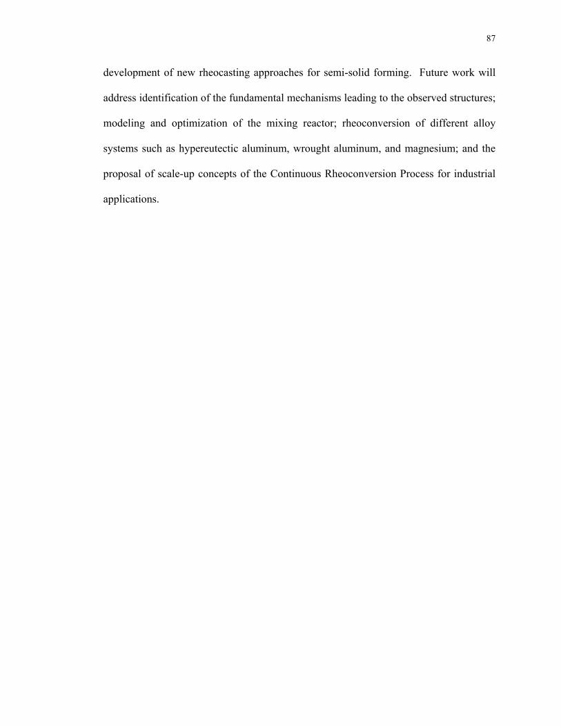
87
development of new rheocasting approaches for semi-solid forming. Future work will
address identification of the fundamental mechanisms leading to the observed structures;
modeling and optimization of the mixing reactor; rheoconversion of different alloy
systems such as hypereutectic aluminum, wrought aluminum, and magnesium; and the
proposal of scale-up concepts of the Continuous Rheoconversion Process for industrial
applications.

88
7. References
1.
2.
3.
4.
5.
6.
7.
8.
9.
10.
11.
M.C. Flemings: Metallurgical Transactions, Vol. 22A, 1991, pp.957-981.
A. de Figueredo and D. Apelian: Science and Technology of Semi-Solid Metal
Processing, edited by A. de Figueredo, published by NADCA, 2001.
D. Apelian, J. Jorstad, and A. de Figueredo: Science and Technology of Semi-Solid
Metal Processing, edited by A. de Figueredo, published by NADCA, 2001.
D.B. Spencer, Ph.D. Thesis, Massachusetts Institute of Technology, Cambridge,
MA, 1971.
D.B. Spencer, R. Mehrabian, and M.C. Flemings: Metallurgical Transactions, Vol.
3, 1972, pp.1925-1932.
M.C. Flemings: Solidification Processing, McGraw-Hill Book Company, New York,
NY, 1974.
D.H. Kirkwood, International Materials Reviews, Vol. 39, No. 5, 1994, pp.173-189.
N. Tonmukayakul, Q.D. Nguyen, A. de Figueredo, and Q.Y. Pan: Proceedings of the
7th International Conference on Semi-Solid Processing of Alloys and Composites,
Tsukuba, Japan, pp.437-442, 2002.
J. Jorstad, Science and Technology of Semi-Solid Metal Processing, edited by A. de
Figueredo, published by NADCA, 2001.
S. Udvardy, Science and Technology of Semi-Solid Metal Processing, edited by A.
de Figueredo, published by NADCA, 2001.
R.D. Doherty, H. Lee, and E.A. Feest: Materials Science and Engineering, Vol. 65,
1984, pp.181-189.

89
12.
13.
14.
15.
16.
17.
18.
19.
20.
21.
22.
23.
J.M.M. Molenaar, L. Katgerman, W.H. Kool, and R.J. Smeulders: Journal of
Materials Science, Vol. 21, 1986, pp.389-394.
D. Apelian: Proceedings of the 6th International Conference on Semi-Solid
Processing of Alloys and Composites, Turino, Italy, pp.47-54, 2000.
H. Wang, C.J. Davidson, J.A. Taylor, and D.H. St. John: Materials Science Forums,
Vol. 396-402, pp.143-148, 2002.
K. Xia and G. Tausig: Materials Science and Engineering, Vol. A246, pp.1-10,
1998.
UBE Industries, Ltd.: European Patent EP 0 745 694 A1, 1996.
T. Motegi, F. Tanabe, and E. Sugiura: Materials Science Forums, Vol. 396-402,
pp.203-208, 2002.
R.A. Martinez, J.A. Yurko, A.M. de Figueredo, and M.C. Flemings: NADCA
Transactions, pp.47-54, 2001.
M.C. Flemings, R.A. Martinez-Ayers, A.M. de Figueredo, and J.A. Yurko: United
States Patent US 2002/0096231 A1, 2002.
J.A. Yurko, R.A. Martinez, and M.C. Flemings: Proceedings of the 7th International
Conference on Semi-Solid Processing of Alloys and Composites, Tsukuba, Japan,
pp.659-664, 2002.
N. Alem, M.S. Thesis, Worcester Polytechnic Institute, Worcester, MA, 2002.
W.R. Loué, M. Suéry: Materials Science and Engineering, Vol. A203, pp.1-13,
1995.
E. Tzimas and A. Zavaliangos, Materials Science and Engineering, Vol. A289,
pp.228-240, 2000.
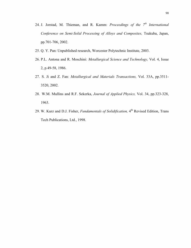
90
24.
25.
26.
27.
28.
29.
J. Jorstad, M. Thieman, and R. Kamm: Proceedings of the 7th International
Conference on Semi-Solid Processing of Alloys and Composites, Tsukuba, Japan,
pp.701-706, 2002.
Q. Y. Pan: Unpublished research, Worcester Polytechnic Institute, 2003.
P.L. Antona and R. Moschini: Metallurgical Science and Technology, Vol. 4, Issue
2, p.49-58, 1986.
S. Ji and Z. Fan: Metallurgical and Materials Transactions, Vol. 33A, pp.3511-
3520, 2002.
W.M. Mullins and R.F. Sekerka, Journal of Applied Physics, Vol. 34, pp.323-328,
1963.
W. Kurz and D.J. Fisher, Fundamentals of Solidification, 4th Revised Edition, Trans
Tech Publications, Ltd., 1998.

91
Appendix A: Micrograph Gallery
In this thesis, the microstructures presented were intended to provide the reader
with evidence that the CRP produces thixotropic microstructures under a variety of
processing conditions. However, in one experiment (R2-2) some other, very interesting
microstructural features were observed that were not pertinent to the topics previously
discussed. Therefore, in this section, some of these features will be presented. The
morphologies of these samples are noticeably different than many of those shown in the
results and discussion section, but it should be stressed that the following micrographs
portray isolated regions of the produced slurry, and do not reflect the entirety of the
sample.
Figure A-1: Experiment R2-2; Tslurry=597°C. (Left) Typical structure throughout
sample; (Right) isolated region of dendritic growth. Note the large size of the dendrite, which likely originated from a small portion of liquid that exited the reactor above its
liquidus temperature.

92
Figure A-2: Experiment R2-2; Tslurry=590°C. (Left) Typical structure throughout
sample; (Right) isolated region of dendritic growth.
Figure A-3: Experiment R2-2; Tslurry=585°C. (Left) Typical structure throughout
sample; (Right) isolated region of dendritic growth. Unusual dendritic morphologies seen throughout the picture at the right.
Figure A-4: Experiment R2-2; Tslurry=605°C. (Left) Typical structure throughout
sample; (Right) isolated region of dendritic growth.

93
Figure A-5: Experiment R2-2; As-solidified structure. (Left) 25X; (Right) 50X. The
presence of the observed eutectic “pool” was not seen in any other samples, but it could be a normal phenomenon due to liquid segregation. “Chinese script” phase observed within the pool is likely the compound Al8Mg3FeSi6, while the black phase seen above
this region is probably Mg2Si.
Figure A-6: Experiment R3-2; Tslurry=585°C. (Left) Non-primary phase particle
(possibly β-Si) which seems to be nucleating α-Al; (Right) Quenching artifacts near the thermocouple’s stainless steel protection sheath (far right).

94
Figure A-7: Experiment R2-2; Tslurry=575°C. (Left) 50X, showing several more non-primary phase particles resembling β-Si; (Right) 400X, close-up of acicular Al5FeSi
intermetallic compound.
The presence of primary silicon particles in the above samples is a strange
phenomenon that was not seen in any other samples in this work. Although the
temperature reading when this sample was removed and quenched was 575°C, this
particular sample was much higher in temperature, probably around 610°C, as indicated
by the high fraction of quenched eutectic. Under the high cooling rate experienced by
the slurry, it is feasible that small pockets of Si-enriched liquid were able to form β-Si
particles. In Figure A-6, the nucleation of α-Al dendrites directly on this particle also
suggests that this phase is primary silicon. Figure A-8 shows SEM micrographs of these
particles, which were verified by EDX to be primary Si.

95
Figure A-8: SEM micrographs of the primary Si particles observed in Figure A-7 (top);
EDX spectrum of the particle in the right-hand picture, showing only the presence of silicon (bottom).

96
Figure A-9: Experiment R2-2. (Left) Tslurry=575°C (Right) Tslurry=605°C. Well-
developed dendrites observed.
Figure A-10: (Left) Experiment R3-4, transition zone between globular and dendritic morphologies; Tslurry=585°C (Right) Experiment R3-5, quenching artifacts adjacent to
thermocouple’s stainless steel protection sheath; Tslurry=585°C.

97
Appendix B: Control experiments – Liquid metal transport tubes
Two experiments were carried out in which the liquid metal flowed from the
transport tubes directly into a volume of cold water. In one experiment, the tubes were
heated to ten degrees above the melt temperature, as was done in all experiments carried
out in this study. In the other, the tubes were kept at room temperature. The purpose
was to ascertain that no nucleation took place in along the walls of the tubes en route to
the reactor. The temperature of the melts prior to their exit from the melting crucibles
was 625°C. The liquid metal was collected in a crucible at room temperature, and
allowed to solidify in air. A thermocouple located at the exit of the tube measured the
temperature of the liquid before depositing into the water. The alloy used was A356.2
with TiB2. Table B-1 shows the thermal data for these two experiments.
Table B-1: Conditions and thermal data for the tube control experiments. Expt. Tliquid Ttube Texit
TC-1 625 635 620
TC-2 625 30 614
As seen in the above Table, when the tube was heated to ten degrees above the
temperature of the transported liquid, only about 5 degrees were lost. It is possible that
this difference in temperature can be attributed to the cooling effect of the air as the
liquid exited the tube. On the other hand, using a cold tube clearly results in more heat
being lost in the transported liquid, such that its temperature upon exit is just below the
liquidus. Figures B-1 and B-2 show the microstructures of each sample.
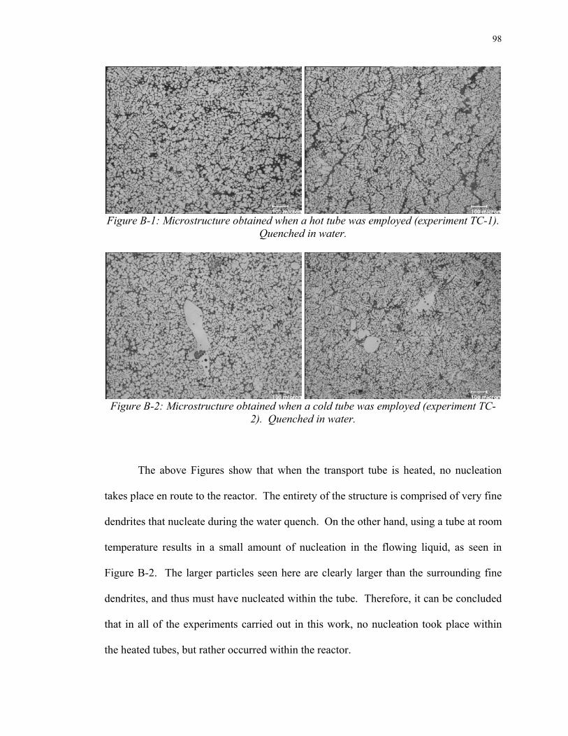
98
Figure B-1: Microstructure obtained when a hot tube was employed (experiment TC-1).
Quenched in water.
Figure B-2: Microstructure obtained when a cold tube was employed (experiment TC-
2). Quenched in water.
The above Figures show that when the transport tube is heated, no nucleation
takes place en route to the reactor. The entirety of the structure is comprised of very fine
dendrites that nucleate during the water quench. On the other hand, using a tube at room
temperature results in a small amount of nucleation in the flowing liquid, as seen in
Figure B-2. The larger particles seen here are clearly larger than the surrounding fine
dendrites, and thus must have nucleated within the tube. Therefore, it can be concluded
that in all of the experiments carried out in this work, no nucleation took place within
the heated tubes, but rather occurred within the reactor.