semi-autonomous personal care robots interface driven by
TRANSCRIPT
Semi-Autonomous Personal Care Robots Interface driven by EEG Signals Digitization
Abstract— In this paper, we propose an innovative architecture that merges the Personal Care Robots (PCRs) advantages with a novel Brain Computer Interface (BCI) to carry out assistive tasks, aiming to reduce the burdens of caregivers. The BCI is based on movement related potentials (MRPs) and exploits EEG from 8 smart wireless electrodes placed on the sensorimotor area. The collected data are firstly pre-processed and then sent to a novel Feature Extraction (FE) step. The FE stage is based on symbolization algorithm, the Local Binary Patterning, which adopts end-to-end binary operations. It strongly reduces the stage complexity, speeding the BCI up. The final user intentions discrimination is entrusted to a linear Support Vector Machine (SVM). The BCI performances have been evaluated on four healthy young subjects. Experimental results showed a user intention recognition accuracy of ~84 % with a timing of ~ 554 ms per decision. A proof of concept is presented, showing how the BCI-based binary decisions could be used to drive the PCR up to a requested object, expressing the will to keep it (delivering it to user) or to continue the research.
Keywords—Personal Care Robot, BCI, LBP, Feature Extraction
I. INTRODUCTION Patients with severe motor disabilities caused by strokes, amyotrophic lateral sclerosis, spinal injuries and so on, often loss their abilities in communicating, moving independently and taking care of their own daily life needs [1]. For these reasons, they require qualified and continuous assistance (i.e., 24/7), but it is often not possible to give them all the care they deserve. In the assistive context, several kinds of Personal Care Robots (PCRs) have been introduced aiming to reduce the caregivers' burdens. In this respect, the PCRs are designed and implemented to carry out some simple care tasks such as goods delivering, social sphere extension (via remote dialogs), temperature and lighting monitoring and adjusting, etc. [1-4]. Contextually, also the human-robot interaction (HRI) concept has been recently revised, taking care of the needs and the physical limitations of even growing catchment area. In fact, the HRIs are recently approaching the Brain-Computer Interfaces (BCIs). BCIs are able to create a direct connection among the brain activity, which reflects the user intentions, and an external device (e.g., the robot), minimizing the physical interaction. This kind of solution fits with the bedridden patients limits, potentially increasing their autonomy. Table 1 summarizes some state-of-the-art solutions implementing BCI and PCRs in the
Ambient Assisted Living context (AAL) [2-4]. The table reports the BCI-based architecture features in terms of used acquisition device, involved BCI methodologies, the BCI core information transfer rate (ITR) and its accuracy. The table also reports the implemented BCI switch-on procedure, and some AAL typical actions to be implemented on the PCR. These actions are condensed in four macro groups: navigation (robot navigation in the environment), exploration (robot head movement to scan object), object recognition and object manipulation procedures. In this respect, authors in [2] propose a low-cost architecture based on the hybrid use of three different BCIs to drive a humanoid robot. Specifically, in the proposed architecture navigation and exploration are entrusted to a steady-state visual evoked potential (SSVEP) BCI [2]. To elicit the SSVEPs, the continuous flickering on a screen is needed. Experimental results show that moving the robot of ~5 m requires ~762 s, easily resulting in user fatigue. Moreover, using three different BCIs and protocols, the system highlights its propensity to BCI illiteracy phenomenon. The authors of [3] proposed an EOG/EEG hybrid architecture used to remotely demand and receive an object, from a target person, which will be brought back to the user. This system navigation procedure is based on the eye movements’ classification among blinks (double or triple), winks and frowns. A simple AAL task (ask pick deliver) requires ~152 s of eye movements, resulting in a somatic muscles useless effort. Finally, the authors in [4] consider the possibility of implementing a fully automatized object manipulation, generally driven by a P300 BCI. Mounting a robotic arm on a wheelchair, the user can require the arm up through 4 general actions. The arm automatically actuates the manipulation by means of a robotic arm stereo vision approach. Each action selection requires ~9 s reducing the ITR. The low number of available choices and the high number of channels to be monitored represent some system drawbacks [5]. In this work, we propose a first-of-a-kind PCR-based architecture for AAL, which exploits a BCI approach to facilitate the patient requests formalization (with potentially infinite options) and takes into account any possible on-going patient changes of idea. The here-proposed system application embeds fully automated PCR navigation and exploration actions, supports the user in the choices by means of an expandable selection tree available via BCI (always connected with the smart environment), gives a continuous video feedback in order to adjust the request in real-time if needed. Specifically, the proposed BCI exploits movement-related potentials (MRPs) from sensorimotor cortical area to provide the PCR a specific and unambiguous command.
Giovanni Mezzina, Daniela De Venuto Dept. of Electrical and Information Engineering
Politecnico di Bari 70125 Bari, Italy
{giovanni.mezzina, daniela.devenuto}@poliba.it
This work was supported by the the project AMICO (Assistenza Medicale InCOntextual awareness, AMICO_Project_ARS01_00900) by National Programs (PON) of the Italian Ministry of Education, Universities and Research(MIUR): Decree n.267.
264978-3-9819263-4-7/DATE20/ c©2020 EDAA
Authorized licensed use limited to: University of Canberra. Downloaded on June 25,2020 at 03:05:23 UTC from IEEE Xplore. Restrictions apply.
In the BCI context, the work also proposes a novel Feature Extraction (FE) based on an end-to-end binary algorithm, named Local Binary Patterning (LBP). The design aims to speed up the final decision achievement. The BCI outcome is then automatically formalized via software and sent through an SSH command to the PCR, which will complete the task. The paper is structured as follows. Sec. II shows and discusses the overall architecture, describing the system working principle. The Sec. III provides implementation details about the blocks that compose the overall architecture. Sec. IV discusses the experimental results and Sec. V concludes the paper.
II. PLATFORM OVERVIEW
A. The Overall Architecture A high-level representation of the proposed architecture is shown in Fig.1 as block diagram. The system can be divided into 4 main sections: (1) the bedridden patient, (2) the Brain Computer Interface, (3) the Personal Care Robot System and (4) the Environment. The former section (i.e., the patient) is composed of the EEG signals acquisition equipment and a terminal for the audio/video stimulation of the cortical potentials. The second one (i.e., the BCI) includes the algorithm that translates the brain activity in practical commands for the PCR and the stimulation protocol management. The third block (i.e., the PCR System) consists of a humanoid robot, which carries out tasks, such as bringing goods (food and drink) or looking for help (caregivers or emergency call). In this application, we used the developer version of PEPPER robot by SoftBank Robotics [8].
Finally, the Environment block consists of a set of sensors and markers distributed into the environment to facilitate robot navigation or to provide an always-updated list of available choices. B. Working principle The overall system working principle can be summarized as follows. Firstly, the patient must get the PCR attention (switch-on procedure). We decided that blinking eyes three times in a short time (< 3 s), activates the BCI. Once activated, the video terminal shows the simplified visual interface as in Fig. 2.a. Since the implemented BCI permits a binary discrimination, the screen always contains two lists of action (e.g., Bring me… or Call … - Fig. 2.a), a section dedicated to the System Messages (SM) and a block dedicated to the video streaming (if enabled). The lists of actions are typically nested and can be enabled via BCI outcomes up to create the final request. The Fig 2.b shows an example in which the user (U) selects the Bring me… command. Then, the robot (R) proposes a second binary choice: {Food, Drink}, and so on. If the user asks for the List of Choices, the robot points at its own memory to find the last updated list of available choices provided by the Environment (E), showing it in the SM area. When enabled, the stimulation system embedded in the BCI waits for 1 s, then plays a buzzer. At that moment, the user is asked to slightly move the coherent side index (e.g. left-hand index Bring me…, right-hand index
Call…). The BCI algorithm analyzes the EEG for 550 ms after the sound and provides the prediction to the PCR. The protocol interface is then refreshed with the next binary choice.
Fig. 1 Block diagram of the proposed platform
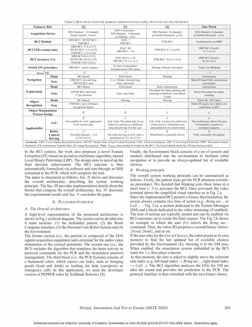
TABLE I. BCI APPLICATION FOR AMBIENT ASSISTED LIVING (AAL): STATE OF THE ART OVERVIEW Features\ Ref. [2] [3] [4] Our Work
Acquisition Device EEG Headset – 14 channels Emotiv Epoch - Emotiv
EOG 6 electrodes + EEG Headset – 8 channels
g.USBamp – gTec
EEG Headset- 16 channels g.Nautilus Research - g.Tec
EEG Headset- 8 channels g.Nautilus Research - g.Tec
BCI Method ERD BCI + SSVEP BCI + P300 BCI
EOG + ERP BCI P300 BCI Symbolization on MRP
BCI ITR (comm./min) ERD BCI: 11.8 (±3.7)
SSVEP BCI: 11.6 (±3.9) P300 BCI: 12.5 (±3.0)
EOG2: 60 ERP BCI: ~ 10 P300 BCI: 6.7 (± 0.63) MRP BCI (Symb.)
11.5 (±2.4)
BCI Accuracy (%) ERD BCI 84.6 (±5.3)
SSVEP BCI 84.4 (±5.0) P300 BCI 89.5 (N.A.)
EOG: 88.8 (± 1.9) ERP BCI: 87.3 (± 6.1) P300 BCI: 82.6 (± 14.4) MRP BCI (Symb.):
84.34 (±0.6)
Switch ON procedure ERD BCI - motor imagery No turn on procedure: Asynchronous EOG check Missing: Manual Activation Triple Eye Blinking
tSWON1 (s) ~ 8 < 3 - < 3
Navigation Mode BCI-based EOG-based Missing Autonomous
Note ERD BCI: forward/stop SSVEP BCI: turn
2 or 3 Blinks: forward/stop Gaze: turn body - Mark ID based fully autonomous
movements
Exploration Mode BCI-Based EOG-based Semi-Autonomous Autonomous
Note SSVEP BCI: turn head 3° per decision Gaze: turn body
Procedure for object picking and scanning via Robotic Arm Stereo
Vision
Preset Procedure for object scanning
Object Recognition
Mode BCI-Based Missing Missing Robot IR +BCI label
Note P300 BCI: up to 4 human recognized objects - - Robot IR engine set a label to be
confirmed via BCI Object Manipulation
Process Design
Applicability
AAL
Not suitable for AAL application in its current state
AAL Task: The robot asks for an object to a person in a different zone and provide it to the user.
AAL Task: Control of a robot arm
connected to a wheelchair (not automatized in its current state)
The architecture allows the user
to formalize a number of assistance requests.
Robot Control Driving
Travelled distance: ~5 m
in 762.3±0.4 s
The robot driving in AAL task is
performed in 151.16±27.9 s
Wheelchair is externally driven
Fully Automatic Navigation
Acronyms: ERD: Event-related desynchronization; SSVEP: Steady State Visual Evoked Potential; EOG: Electroocoulogram; ERP: Event-related Potential; MRP: Movement-related Potentials; ITR: Information Transfer Rate; IR: Image Recognition. Note: 1tSWON: time needed to switch-on the BCI; 2 No formal details about the ITR has been provided.
Design, Automation And Test in Europe (DATE 2020) 265
Authorized licensed use limited to: University of Canberra. Downloaded on June 25,2020 at 03:05:23 UTC from IEEE Xplore. Restrictions apply.
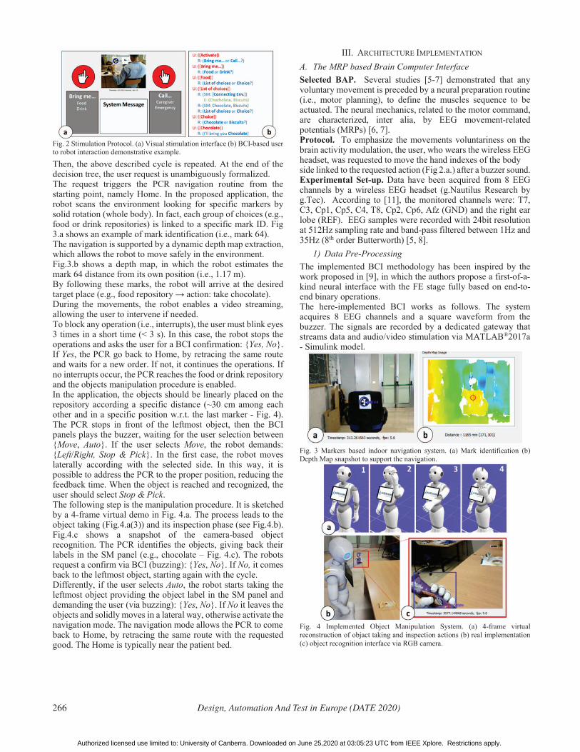
Fig. 2 Stimulation Protocol. (a) Visual stimulation interface (b) BCI-based user to robot interaction demonstrative example.
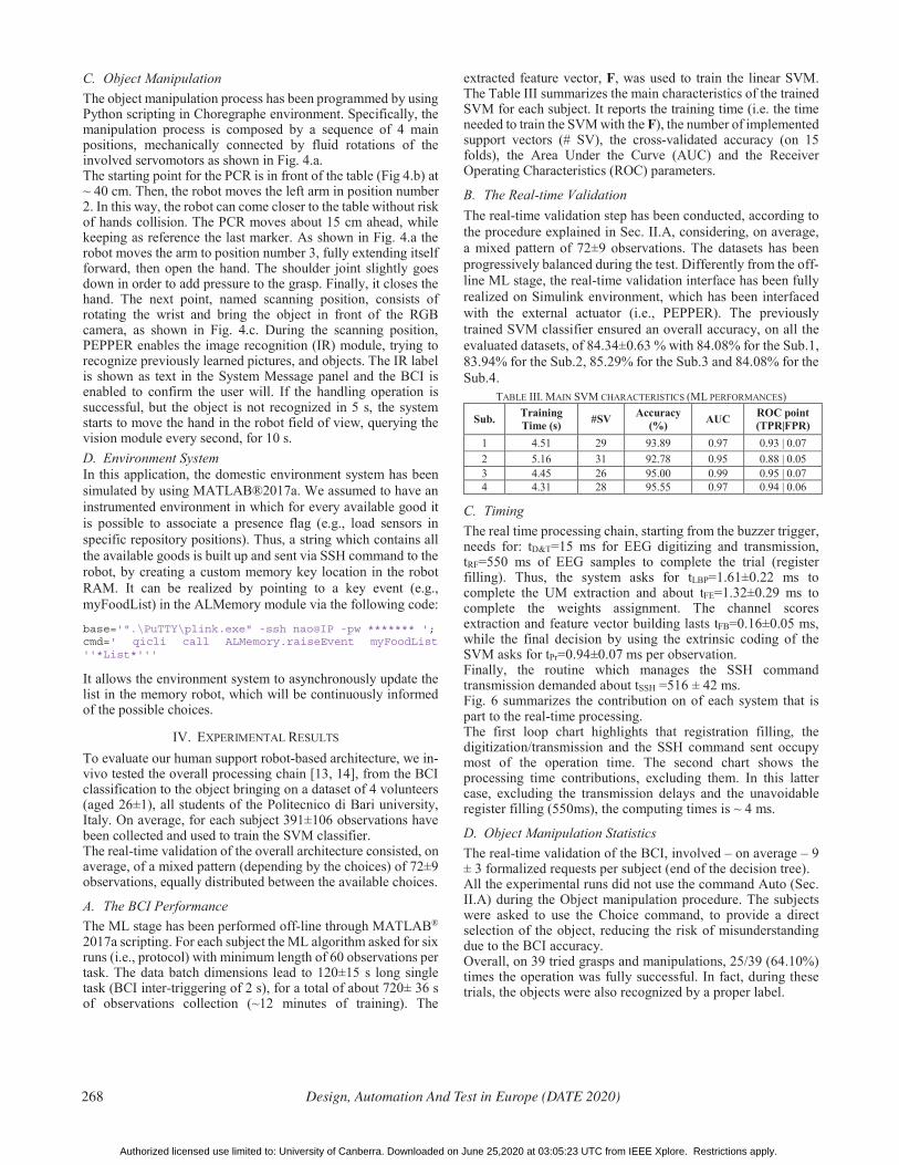
Then, the above described cycle is repeated. At the end of the decision tree, the user request is unambiguously formalized. The request triggers the PCR navigation routine from the starting point, namely Home. In the proposed application, the robot scans the environment looking for specific markers by solid rotation (whole body). In fact, each group of choices (e.g., food or drink repositories) is linked to a specific mark ID. Fig 3.a shows an example of mark identification (i.e., mark 64). The navigation is supported by a dynamic depth map extraction, which allows the robot to move safely in the environment. Fig.3.b shows a depth map, in which the robot estimates the mark 64 distance from its own position (i.e., 1.17 m). By following these marks, the robot will arrive at the desired target place (e.g., food repository action: take chocolate). During the movements, the robot enables a video streaming, allowing the user to intervene if needed. To block any operation (i.e., interrupts), the user must blink eyes 3 times in a short time (< 3 s). In this case, the robot stops the operations and asks the user for a BCI confirmation: {Yes, No}. If Yes, the PCR go back to Home, by retracing the same route and waits for a new order. If not, it continues the operations. If no interrupts occur, the PCR reaches the food or drink repository and the objects manipulation procedure is enabled. In the application, the objects should be linearly placed on the repository according a specific distance (~30 cm among each other and in a specific position w.r.t. the last marker - Fig. 4). The PCR stops in front of the leftmost object, then the BCI panels plays the buzzer, waiting for the user selection between {Move, Auto}. If the user selects Move, the robot demands: {Left/Right, Stop & Pick}. In the first case, the robot moves laterally according with the selected side. In this way, it is possible to address the PCR to the proper position, reducing the feedback time. When the object is reached and recognized, the user should select Stop & Pick. The following step is the manipulation procedure. It is sketched by a 4-frame virtual demo in Fig. 4.a. The process leads to the object taking (Fig.4.a(3)) and its inspection phase (see Fig.4.b). Fig.4.c shows a snapshot of the camera-based object recognition. The PCR identifies the objects, giving back their labels in the SM panel (e.g., chocolate – Fig. 4.c). The robots request a confirm via BCI (buzzing): {Yes, No}. If No, it comes back to the leftmost object, starting again with the cycle. Differently, if the user selects Auto, the robot starts taking the leftmost object providing the object label in the SM panel and demanding the user (via buzzing): {Yes, No}. If No it leaves the objects and solidly moves in a lateral way, otherwise activate the navigation mode. The navigation mode allows the PCR to come back to Home, by retracing the same route with the requested good. The Home is typically near the patient bed.
III. ARCHITECTURE IMPLEMENTATION A. The MRP based Brain Computer Interface Selected BAP. Several studies [5-7] demonstrated that any voluntary movement is preceded by a neural preparation routine (i.e., motor planning), to define the muscles sequence to be actuated. The neural mechanics, related to the motor command, are characterized, inter alia, by EEG movement-related potentials (MRPs) [6, 7]. Protocol. To emphasize the movements voluntariness on the brain activity modulation, the user, who wears the wireless EEG headset, was requested to move the hand indexes of the body side linked to the requested action (Fig 2.a.) after a buzzer sound. Experimental Set-up. Data have been acquired from 8 EEG channels by a wireless EEG headset (g.Nautilus Research by g.Tec). According to [11], the monitored channels were: T7, C3, Cp1, Cp5, C4, T8, Cp2, Cp6, Afz (GND) and the right ear lobe (REF). EEG samples were recorded with 24bit resolution at 512Hz sampling rate and band-pass filtered between 1Hz and 35Hz (8th order Butterworth) [5, 8].
1) Data Pre-Processing The implemented BCI methodology has been inspired by the work proposed in [9], in which the authors propose a first-of-a-kind neural interface with the FE stage fully based on end-to-end binary operations. The here-implemented BCI works as follows. The system acquires 8 EEG channels and a square waveform from the buzzer. The signals are recorded by a dedicated gateway that streams data and audio/video stimulation via MATLAB®2017a - Simulink model.
Fig. 3 Markers based indoor navigation system. (a) Mark identification (b) Depth Map snapshot to support the navigation.
Fig. 4 Implemented Object Manipulation System. (a) 4-frame virtual reconstruction of objact taking and inspection actions (b) real implementation (c) object recognition interface via RGB camera.
266 Design, Automation And Test in Europe (DATE 2020)
Authorized licensed use limited to: University of Canberra. Downloaded on June 25,2020 at 03:05:23 UTC from IEEE Xplore. Restrictions apply.

Firstly, the square waveform from buzzer is software-delayed of 350 ms, giving the user a suitable reaction time. Then its rising edge is used to trigger the extraction of a subset of EEG data from all the channels: the EEG trial. The EEG trial consists of a time-windowed EEG of 1.25 s (Ns = 648 samples) across the buzzer trigger. Practically, it consists of 0.7 s before the actual trigger rising edge, and 0.55 s after it [9, 10]. Since the EEGs are typically affected by physiological (e.g., eye blink) and non-physiological artifacts, the trials undergo a pre-processing stage that consists of an online artifacts rejection method: the Riemannian Artifact Subspace Reconstruction (rASR) [11]. The method extracts the artifacts-free EEG, isolating the independent components (IC) that compose the artifacts. In the current application, the BCI extracts two outcomes from this stage: (1) the IC linked to the eye blink signal (useful for the human-robot interface activation) and (2) the artifacts-free EEGs for the requests to be sent to the PCR.
2) Offline Machine Learning During a first offline machine learning (ML) stage the user is asked to realize the above-mentioned protocol (Sec. III.A) but, this time, by following a guided and known pattern. Considering the Fig.2.a, one of the red circles is colored by blue, identifying the hand to be moved after the buzzer sound. The user must move the coherent side finger to enable the data collection. Each monitored channel is singularly analyzed by the symbolization routine. In this stage, the EEG trials from all channels are translated in 2D matrices (bEEG) and queued in 1st dimension, realizing a binary matrix with dimension {24 x 10}. The here-implemented Local Binary Patterning algorithm can be summarized by the following pseudocode:
TABLE II. LBP ROUTINE ALGORITHM Algorithm: LBP Routine
Input: Tr // Single Channel EEG Trial {1x40} div 10; // Divide the trial in 10 parts (4 samples) w_len length(Tr)/div;
for k=1:div sig Tr(((k-1)*w_len)+1: k*w_len); // Scroll the ten 4-sample blocks for i=w_len:-1:2 // Analyze contiguous elements; assign the value if (sig(i)-sig(i-1))>0 c(i-1) 1; // Temporary column vector else c(i-1) 0; // Temporary column vector
bEEG(:,k)= c; // Build the LBP output matrix {3x10} Output: bEEG
During the learning task, the bEEGs are queued along the 3rd dimension realizing a 3D binary matrix. In reality, differentiating per trained side, the trials define two 3D matrices (one per choice, left and right) that size {24 x 10 x Nobs}, where Nobs is the number of the analyzed trials. For each matrix, the BCI extracts, element-by-element, the percentage of “1” occurred along all the Nobs trials. It defines two 2D binary matrices with the same bEEG size, AvgLH (left-hand movements) and AvgRH (right-hand movements). If an (i,j) element tend to “1”, it means that the pointed element is typically linked to an increasing trend of the EEG, otherwise a decreasing one (see LBP routine in Table II). Feature Extraction. In this stage, the BCI firstly analyzes via LBP the incoming trial (labeled during learning or unlabeled during classification), extracting a binary matrix bEEG that we name Unlabeled Matrix (UM) referring to an online recognition
case. The BCI multiplies, element-by-element, the UM with the AvgLH and AvgRH, virtually extracting two score matrices. The BCI sums row-by-row the scores, and then it extends the sum to all the rows interested by the single channels, obtaining a single score per channel. At the end of the procedure, the system has extracted 16 scores: the first 8 related to the comparison with AvgLH, while the remaining 8 are linked to the AvgRH. These values compose the features vector. Briefly, if an UM acts in a similar manner with AvgLH, thus, the first 8 feature vector values are high and the last eight are low, we can assume that the unlabeled movement can be related to a left-hand movement. Classification Model. The feature vectors from each trial in the learning session are concatenated and labelled (right and left side selection) to realize the train set matrix F 17,Nobs , in which each row is defined as: {Fi Nf, Li}, where i=1…Nobs and Li is the i-th trial label: Yi=-1 Left hand movement, while Yi= 1 Right hand movement. The F matrix has been used to train a Support Vector Machine (SVM) [12] with a linear kernel.
3) Online Intention Recognition and PCR Interfacing During its real-time working, first, the BCI waits for the eye blink activation (Sec. II.B). It simply consists in the presence verification of 3 amplitude peaks (< 3 s) on the eye blink related ICs from the rASR block. Once activated, the BCI waits for 1 s, then starts buzzing following the previously described modalities (Sec. II.B). Specifically, the BCI proceeds with the LBP routine on the extracted EEG trial to be analyzed. The resulting UM undergoes the FE stage (Sec III.A.2) generating an unlabeled feature vector. Finally, this vector is sent to the trained SVM, which classifies the user intention. The SVM prediction is used to select an action between the two points on the lists of actions shown in the BCI visual panel. If the request corresponds to the last step of the decisional tree, the implemented system sends an SSH command to the robot, annotating the final request in the robot memory and contextually enabling the PCR navigation. B. The Navigation System Once activated via BCI, the PCR (i.e., PEPPER) enables the built-in OV5640 RGB camera on the head top [9] and the 3D camera (ASUS Xtion 3D sensor) located in the forehead. Both allows the PCR generating a depth space color space between 0.4 m and 8 m (0.005 m resolution). More in detail, the PCR uses the built-in vision recognition module to scan the environment, looking for the mark ID related to the specific request (Fig. 3.a). If no marks are detected, the PCR solidly moves around with a preset rotation angle (i.e., 5°), then tries again to recognize marks in the field of view. If a mark is detected, the robot centers its body in front of the target and extracts the depth map (Fig. 3.b), otherwise actuates postural adjustments. The distance is stored and conservatively reduced of 40 cm (for collision avoidance), then the robot moves in the x-axis direction, reaching the new starting point. Once the position is reached, the PCR discards the last seen marker and starts looking for new markers. If no new markers are detected, it means that the final position has been reached. The robot keeps in memory all the movements to coming back at Home.
Design, Automation And Test in Europe (DATE 2020) 267
Authorized licensed use limited to: University of Canberra. Downloaded on June 25,2020 at 03:05:23 UTC from IEEE Xplore. Restrictions apply.
C. Object Manipulation The object manipulation process has been programmed by using Python scripting in Choregraphe environment. Specifically, the manipulation process is composed by a sequence of 4 main positions, mechanically connected by fluid rotations of the involved servomotors as shown in Fig. 4.a. The starting point for the PCR is in front of the table (Fig 4.b) at ~ 40 cm. Then, the robot moves the left arm in position number 2. In this way, the robot can come closer to the table without risk of hands collision. The PCR moves about 15 cm ahead, while keeping as reference the last marker. As shown in Fig. 4.a the robot moves the arm to position number 3, fully extending itself forward, then open the hand. The shoulder joint slightly goes down in order to add pressure to the grasp. Finally, it closes the hand. The next point, named scanning position, consists of rotating the wrist and bring the object in front of the RGB camera, as shown in Fig. 4.c. During the scanning position, PEPPER enables the image recognition (IR) module, trying to recognize previously learned pictures, and objects. The IR label is shown as text in the System Message panel and the BCI is enabled to confirm the user will. If the handling operation is successful, but the object is not recognized in 5 s, the system starts to move the hand in the robot field of view, querying the vision module every second, for 10 s. D. Environment System In this application, the domestic environment system has been simulated by using MATLAB®2017a. We assumed to have an instrumented environment in which for every available good it is possible to associate a presence flag (e.g., load sensors in specific repository positions). Thus, a string which contains all the available goods is built up and sent via SSH command to the robot, by creating a custom memory key location in the robot RAM. It can be realized by pointing to a key event (e.g., myFoodList) in the ALMemory module via the following code:
base='".\PuTTY\plink.exe" -ssh nao@IP -pw ******* '; cmd=' qicli call ALMemory.raiseEvent myFoodList ''*List*'''
It allows the environment system to asynchronously update the list in the memory robot, which will be continuously informed of the possible choices.
IV. EXPERIMENTAL RESULTS To evaluate our human support robot-based architecture, we in-vivo tested the overall processing chain [13, 14], from the BCI classification to the object bringing on a dataset of 4 volunteers (aged 26±1), all students of the Politecnico di Bari university, Italy. On average, for each subject 391±106 observations have been collected and used to train the SVM classifier. The real-time validation of the overall architecture consisted, on average, of a mixed pattern (depending by the choices) of 72±9 observations, equally distributed between the available choices.
A. The BCI Performance The ML stage has been performed off-line through MATLAB® 2017a scripting. For each subject the ML algorithm asked for six runs (i.e., protocol) with minimum length of 60 observations per task. The data batch dimensions lead to 120±15 s long single task (BCI inter-triggering of 2 s), for a total of about 720± 36 s of observations collection (~12 minutes of training). The
extracted feature vector, F, was used to train the linear SVM. The Table III summarizes the main characteristics of the trained SVM for each subject. It reports the training time (i.e. the time needed to train the SVM with the F), the number of implemented support vectors (# SV), the cross-validated accuracy (on 15 folds), the Area Under the Curve (AUC) and the Receiver Operating Characteristics (ROC) parameters.
B. The Real-time Validation The real-time validation step has been conducted, according to the procedure explained in Sec. II.A, considering, on average, a mixed pattern of 72±9 observations. The datasets has been progressively balanced during the test. Differently from the off-line ML stage, the real-time validation interface has been fully realized on Simulink environment, which has been interfaced with the external actuator (i.e., PEPPER). The previously trained SVM classifier ensured an overall accuracy, on all the evaluated datasets, of 84.34±0.63 % with 84.08% for the Sub.1, 83.94% for the Sub.2, 85.29% for the Sub.3 and 84.08% for the Sub.4.
TABLE III. MAIN SVM CHARACTERISTICS (ML PERFORMANCES)
Sub. Training Time (s) #SV Accuracy
(%) AUC ROC point (TPR|FPR)
1 4.51 29 93.89 0.97 0.93 | 0.07 2 5.16 31 92.78 0.95 0.88 | 0.05 3 4.45 26 95.00 0.99 0.95 | 0.07 4 4.31 28 95.55 0.97 0.94 | 0.06
C. Timing The real time processing chain, starting from the buzzer trigger, needs for: tD&T=15 ms for EEG digitizing and transmission, tRF=550 ms of EEG samples to complete the trial (register filling). Thus, the system asks for tLBP=1.61±0.22 ms to complete the UM extraction and about tFE=1.32±0.29 ms to complete the weights assignment. The channel scores extraction and feature vector building lasts tFB=0.16±0.05 ms, while the final decision by using the extrinsic coding of the SVM asks for tPr=0.94±0.07 ms per observation. Finally, the routine which manages the SSH command transmission demanded about tSSH =516 ± 42 ms. Fig. 6 summarizes the contribution on of each system that is part to the real-time processing. The first loop chart highlights that registration filling, the digitization/transmission and the SSH command sent occupy most of the operation time. The second chart shows the processing time contributions, excluding them. In this latter case, excluding the transmission delays and the unavoidable register filling (550ms), the computing times is ~ 4 ms.
D. Object Manipulation Statistics The real-time validation of the BCI, involved – on average – 9 ± 3 formalized requests per subject (end of the decision tree). All the experimental runs did not use the command Auto (Sec. II.A) during the Object manipulation procedure. The subjects were asked to use the Choice command, to provide a direct selection of the object, reducing the risk of misunderstanding due to the BCI accuracy. Overall, on 39 tried grasps and manipulations, 25/39 (64.10%) times the operation was fully successful. In fact, during these trials, the objects were also recognized by a proper label.
268 Design, Automation And Test in Europe (DATE 2020)
Authorized licensed use limited to: University of Canberra. Downloaded on June 25,2020 at 03:05:23 UTC from IEEE Xplore. Restrictions apply.

Fig. 6 Real-time processing timing from the trigger activation. The second loop chart excludes tRF, tD&T and tSSH. Moreover, 5/39 (12.82%) grasps and manipulations were partially successful, since the robot did not recognize the object. The remaining trials (i.e., 9/36 – 25%) consisted of fully missing (i.e., empty hand label) and lost grasps.
E. Breakthrough Points The proposed architecture showed how to exploits the pros of both assistive robots (PCRs) and neural interfaces (BCIs) to realize simple desire-driven action when physical interaction is impossible or problematic. The overall system in Fig.1 solves the patient/user fatiguing calibration phase, typical of the current state of the art solutions [2, 3], when -for example- the PCR is requested to bring objects. In fact, since in this application the patient is not fully engaged in the PCR piloting step-by-step, his fatigue is effectively reduced, while keeping a full control on the robot.The system embeds a BCI that proved to be able to address a still open challenges concerning the priority request in the PCR field: properly understand the patient’s physiological needs and satisfy them. In fact, differently from recent state of the art solutions (Table I) that permit only few static selections (overall < 4 [2-4]), the here proposed BCI is always connected with the environment, allowing the user a dynamic selection list with an ideally infinite number of choices. The BCI nested structure: (i) facilitates the patient requests formalization, also for subjects with strong neuromuscular disabilities and (ii) considers any possible on-going patient changes of idea.
V. CONCLUSIONS In this paper, we proposed a novel architecture that combines the general applicability of Brain Computer Interfaces with the re-programmability of Personal Care Robots automatisms to carry out simple assistive tasks without any fatiguing interaction. Specifically, in this architecture, the BCI focused on the proper understanding and formalization of patients’ needs, while the PCR exploited its automatic routines to satisfy them. The system allows the patient to passively (monitoring) or actively (supervision and adjustments) follow the PCR task. The decision-making part of the architecture has been fully entrusted to a novel symbolization based BCI. The proposed BCI demonstrated, through in-vivo validation on 4 healthy subjects, to be able in reaching a final decision in ~554 ms (with a processing time of ~ 4 ms), while keeping an accuracy of ~84 %. The whole manuscript provides an extended proof of concept, in which the BCI based decisions are used to drive the robot up to the desired object, allowing the user to express the will to keep it or not. The architecture has been structured to permit its
modular improvements [15, 16] and an easy re-programmability in different application contexts.
REFERENCES [1] P. Koleva, K. Tonchev, G. Balabanov, A. Manolova and V. Poulkov,
"Challenges in designing and implementation of an effective Ambient Assisted Living system," 2015 12th International Conference on Telecommunication in Modern Satellite, Cable and Broadcasting Services (TELSIKS), Nis, 2015, pp. 305-308.
[2] Choi, Bongjae, and Sungho Jo. "A low-cost EEG system-based hybrid brain-computer interface for humanoid robot navigation and recognition." PloS one 8.9 (2013): e74583.
[3] J. Ma, Y. Zhang, A. Cichocki and F. Matsuno, "A Novel EOG/EEG Hybrid Human–Machine Interface Adopting Eye Movements and ERPs: Application to Robot Control," in IEEE Transactions on Biomedical Engineering, vol. 62, no. 3, pp. 876-889, March 2015.
[4] D. Achanccaray, J. M. Chau, J. Pirca, F. Sepulveda and M. Hayashibe, "Assistive Robot Arm Controlled by a P300-based Brain Machine Interface for Daily Activities," 2019 9th International IEEE/EMBS Conference on Neural Engineering (NER), San Francisco, CA, USA, 2019, pp. 1171-1174.
[5] Lotte, Fabien, et al. "A review of classification algorithms for EEG-based brain–computer interfaces: a 10 year update." Journal of neural engineering 15.3 (2018): 031005.
[6] De Venuto D., Annese V.F., de Tommaso M., Vecchio E., Sangiovanni Vincentelli A.L. (2015) Combining EEG and EMG Signals in a Wireless System for Preventing Fall in Neurodegenerative Diseases. In: Andò B., Siciliano P., Marletta V., Monteriù A. (eds) Ambient Assisted Living. Biosystems & Biorobotics, vol 11. Springer, Cham
[7] V. F. Annese and D. De Venuto, "The truth machine of involuntary movement: FPGA based cortico-muscular analysis for fall prevention," 2015 IEEE International Symposium on Signal Processing and Information Technology (ISSPIT), Abu Dhabi, 2015, pp. 553-558. doi: 10.1109/ISSPIT.2015.7394398
[8] De Venuto, D., Ohletz, M.J. and Riccò, B. Digital Window Comparator DfT Scheme for Mixed-Signal ICs Journal of Electronic Testing (2002) 18: 121. https://doi.org/10.1023/A:1014937424827
[9] G. Mezzina and D. De Venuto, "Local Binary Patterning Approach for Movement Related Potentials based Brain Computer Interface," 2019 IEEE 8th International Workshop on Advances in Sensors and Interfaces (IWASI), Otranto, Italy, 2019, pp. 239-244. doi: 10.1109/IWASI.2019.8791266
[10] D. De Venuto, V. F. Annese and G. Mezzina, "An embedded system remotely driving mechanical devices by P300 brain activity," Design, Automation & Test in Europe Conference & Exhibition (DATE), 2017, Lausanne, 2017, pp. 1014-1019. doi: 10.23919/DATE.2017.7927139
[11] Blum, Sarah, et al. "A Riemannian modification of Artifact Subspace Reconstruction for EEG artifact handling." Frontiers in human neuroscience 13 (2019): 141.
[12] Chauhan, Vinod Kumar, Kalpana Dahiya, and Anuj Sharma. "Problem formulations and solvers in linear SVM: a review." Artificial Intelligence Review 52.2 (2019): 803-855.
[13] D. De Venuto, M. J. Ohletz and B. Ricco, "Testing of analogue circuits via (standard) digital gates," Proceedings International Symposium on Quality Electronic Design, San Jose, CA, USA, 2002, pp. 112-119. doi: 10.1109/ISQED.2002.996709
[14] D. De Venuto, M. J. Ohletz and B. Ricco, "Automatic repositioning technique for digital cell based window comparators and implementation within mixed-signal DfT schemes," Fourth International Symposium on Quality Electronic Design, 2003. Proceedings., San Jose, CA, USA, 2003, pp. 431-437. doi: 10.1109/ISQED.2003.1194771
[15] Nuchter, Andress, et al. "6D SLAM with an application in autonomous mine mapping." IEEE International Conference on Robotics and Automation, 2004. Proceedings. ICRA'04. 2004. Vol. 2. IEEE, 2004.
[16] Johannsmeier, L., Gerchow, M., and Haddadin, S. (2019, May). A framework for robot manipulation: Skill formalism, meta learning and adaptive control. In 2019 International Conference on Robotics and Automation (ICRA). pp. 5844-585.
Design, Automation And Test in Europe (DATE 2020) 269
Authorized licensed use limited to: University of Canberra. Downloaded on June 25,2020 at 03:05:23 UTC from IEEE Xplore. Restrictions apply.