sem - 500 - ttt environmental · sem-500 user’s guide introduction overview the sem - 500 surface...
TRANSCRIPT
SSuurrffaaccee EEmmiissssiioonn MMoonniittoorr SEM-500 User’s Guide
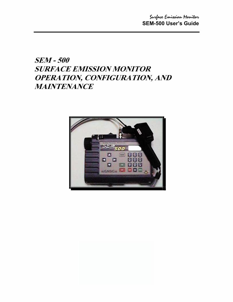
SEM - 500 SURFACE EMISSION MONITOR OPERATION, CONFIGURATION, AND MAINTENANCE

SSuurrffaaccee EEmmiissssiioonn MMoonniittoorr SEM-500 User’s Guide
Instruction Book 3500
SEM - 500 Surface Emissions Monitor
April 13, 1999
CONTENTS Description SEM - 500, Operation, Configuration, and Maintenance WATERTRAP Probe (Part No. CR013EA) - SEM - 500 - Parts List

SSuurrffaaccee EEmmiissssiioonn MMoonniittoorr SEM-500 User’s Guide
TABLE OF CONTENTS Figures Tables General Instructions Introduction Overview Instrument Functions Using the Instrument Standard Specifications External Influences Product Safety Specifications Theory of Operation Flame Ionization Detection (FID) Photoionization Detection Dual Detectors Concentration Calculation and Calibration Hardware Instrument Connections Analog Outputs Instrument Sidepack Display Instrument Sidepack Keypad Probe Connections Enhanced Probe Display Enhanced Probe Keys Startup and Familiarization Quick Start Procedure Display Menus Main Menu Structure Control Menu Setup Procedure Passcode Protection Calibration Scenario 1 Scenario 2 Scenario 3 Calibration Configuration Detector Counts Defining the Span Gas Concentration(s) Defining the Response Factor Alarm Levels

SSuurrffaaccee EEmmiissssiioonn MMoonniittoorr SEM-500 User’s Guide
Log Methods Hardware Configuration (Barcode Reader/Probe Display) User Identification Number Date Time of Day User Options Information Menu PC Link/Memory Run Mode Accessing the Run Menu Using the Enhanced Probe The Enhanced Probe and the RUN Mode Auto Logging with the Enhanced Probe VOC Logging with the Enhanced Probe FE (Fugitive Emissions) Logging with the Enhanced Probe Additional Component Information Maintenance Removable, Renewable Parts Normal Operating Maintenance Battery and Battery Charger Hydrogen Gas Tank Servicing the PID Cartridge Servicing the FID Cartridge Cleaning the FID Detector Cap Replacing the Flame Arrestor Cleaning the FID or PID Detector Cavities Cleaning or Replacing a Sintered Metal Filter Replacing Sample Line Troubleshooting Warning Messages Accessories Telescoping Extension Option Activated Charcoal Filter Adapter Index

SSuurrffaaccee EEmmiissssiioonn MMoonniittoorr SEM-500 User’s Guide
FIGURES
1 Analyzer Sidepack 2 Typical Flame Ionization Detector 3 Typical Photoionization Detector 4 SEM - 500 Dual Detector Configuration 5 SEM - 500 Instrument Connections 6 Keypad 7 Sample Probe Assembly 8 SEM - 500 BASIC Probe Display 9 SEM - 500 Enhanced Probe Display - Menu Mode 10 PID Lamp Cleaning Kit 11 Sintered Metal Filter - Cleaning or Replacing 12 Replacing Sample Line 13 Telescoping Extension Option 14 Activated Charcoal Filter Adapter

SSuurrffaaccee EEmmiissssiioonn MMoonniittoorr SEM-500 User’s Guide
TABLES
1 Specifications 2 External Influences 3 Product Safety Specifications

SSuurrffaaccee EEmmiissssiioonn MMoonniittoorr SEM-500 User’s Guide
GENERAL INSTRUCTIONS CES/LANDTEC designs, manufactures, and tests its products to meet many national and international standards. However, for these products to operate within their normal specifications, you must properly install, use, and maintain these products. The following instructions must be adhered to and integrated with your safety program when installing, using, and maintaining CES/LANDTEC products.
♦ Read and save all instructions prior to installing, operating, and servicing the product.
♦ If you do not understand any of the instructions, contact your CES/LANDTEC
representative for clarification.
♦ Follow all warnings, cautions, and instructions marked on and supplied with the product.
♦ Inform and educate your personnel in the proper installation, operation, and
maintenance of the product.
♦ To ensure proper performance, use qualified personnel to operate, update, program, and maintain the product.
SSuurrffaaccee EEmmiissssiioonn MMoonniittoorr SEM-500 User’s Guide
INTRODUCTION
Overview The SEM - 500 SURFACE EMISSIONS MONITOR is an advanced-design, portable, organic/inorganic vapor monitor for the gas survey industry. This analyzer uses a flame ionization detector (FID) to sample and measure concentration of gases. The vapor concentration may be read immediately on either of two displays—one mounted directly on the hand-held sample probe and the other on the instrument sidepack itself. Vapor concentration can be displayed on both displays in parts per million (ppm), parts per billion (ppb), or percent concentration (%). The data displayed may also be collected and saved in analyzer memory and downloaded to a personal computer for analysis. Through the sidepack keyboard, you can choose the mode of operation, select concentration units for the display, select data collection mode, and change setup (configuration) parameters. This unit is shipped with the battery installed. The unit is ready for operation upon completion of setup, calibration, and charging.

SSuurrffaaccee EEmmiissssiioonn MMoonniittoorr SEM-500 User’s Guide
INSTRUMENT FUNCTIONS This analyzer functions in any of four modes: ♦ RUN ♦ SETUP ♦ INFO ♦ PC LINK/MEMORY In the RUN mode, the instrument automatically displays its measured values in units of ppm, ppb, or %. The RUN mode may be operated either as survey only, in which the instrument displays measured values but does not store any data, or survey and log, in which the instrument displays measured values and also stores the information in memory. In SETUP mode, you can enter or select operational parameters, such as calibration values, operator ID, datalogging method and interval, date, and time. This may be performed locally by using the analyzer keypad or remotely by using the RS – 232 connection to a personal computer (PC). In INFO mode, you can review operational parameters entered or selected in SETUP mode as well as instrument serial number, battery status, etc. In PC LINK/MEMORY mode, you can download data stored within the SEM - 500to a PC for analysis and printing, upload route list, calibration, and configuration parameters from a PC to the SEM - 500, or clear memory. Each of the four modes is explained in detail later in this document.
Using the Instrument While operating this instrument in the field, you normally carry the SEM - 500 at your side, using the shoulder strap. With the pump on, detector on, and the unit warmed up, you monitor the area of concern. As soon as the instrument analyzes a sample, the probe displays concentration of the vapor. The display on the sidepack duplicates the vapor concentration on the probe display.
WARNING: Do not connect/disconnect any electrical device (such as battery charger, analog output, personal computer, or auxiliary port device) to the instrument in an area classified as hazardous due to the presence of flammable vapors.
SSuurrffaaccee EEmmiissssiioonn MMoonniittoorr SEM-500 User’s Guide
INSTRUMENT FUNCTIONS
Standard Specifications
Table 1—Specifications Item Specification
Accuracy FID -- +25% of reading or +2.5 ppm, whichever is greater, from 1.0 to 10,000 ppm. Accuracy listed is achieved using methane with a 1 – point calibration in the range from 100 to 500 ppm (including drift) at the temperature and humidity of the calibration
Repeatability FID -- +2% at 100 ppm of methane Analog Output One analog output signal, 0 to 2 V dc, proportional to the
count output from the detector Dynamic Range FID – 1.0 to 50,000 ppm of methane Linear Range FID – 1.0 to 10,000 ppm of methane Minimum Detectable Level
The minimum detectable level is defined as two times the peak - to - peak noise. FID – 300 ppb of hexane
Response Time using telescoping wand extender
FID – Less than 5.0 seconds for 90% of final value, using 10,000 ppm of methane
Recovery Time using telescoping wand extender
FID – Less than 5.0 seconds to return to 10% of base line, using 10,000 ppm of methane
Data Storage Interval Auto Mode – 1 per second to 1 per 999 minutes, user selectable. (SEM Software sets interval to 4 seconds)
Sample Flow Rate 1 liter/minute, nominal, at sample probe inlet Battery The battery can be fully charged in less than 16 hours. The
battery operating time is 8 hours minimum at 20° C (32°F). Use of the backlight on the probe display shortens battery life. The battery is replaceable by removing the bottom cover of the instrument. (WARNING: Do not replace battery in an area classified as hazardous due to presence of flammable gases or vapors.)
Battery Charger The battery charger is a separate unit capable of operating the analyzer while simultaneously charging the internal battery. An adapter cable is provided to charge the battery separate from the analyzer. The charger can charge a fully discharged battery in a maximum of 16 hours. Charging takes longer if performed while the instrument is operating. (WARNING: Do not operate battery charger in an area classified as hazardous due to presence of flammable gases or vapors.)
FID Life Greater than 2000 hours

SSuurrffaaccee EEmmiissssiioonn MMoonniittoorr SEM-500 User’s Guide
Audio Output Level Greater than 75 dB at 3 feet Gas Cylinder Capacity Pressure – 15.3 Mpa at 25°C (2200 psi at 77°F) maximum
Empty – 85 cc (5.19 in3) Hydrogen Supply Operating Time
Greater than 8 hours of continuous operation, starting from a cylinder charged up to 15.3 Mpa (2200 psi)
Enclosure Description The analyzer enclosure and front panel are made from a chemically resistant thermoplastic material. The approximate dimensions are 343 x 10.3 x 3.2 in). The enclosure is designed to provide environmental protection.
Electric Interface Connections
Mating female connectors for Analog Output, RS – 232 Interface (Host), and Battery Charger are provided on the side of the analyzer case below the keypad.
Mechanical Connections Mechanical connections for Sample Input and for Vent Outlet are provided on the side and bottom surfaces.
Portability The analyzer is designed to be carried by a removable shoulder strap. The strap, which is provided with every instrument, does not hinder the user when viewing or using the analyzer front panel. The strap is designed to support the probe when the instrument is not in use and to carry accessory tools.
Tool Kit An accessory tool kit is provided with each instrument. The kit contains special tools for accessing the battery and removing the detector capsule.
Approximate Mass Analyzer Probe Assembly: Enhanced Probe – 0.79 kg (1.75 lb)
EXTERNAL INFLUENCES This product is intended for use in indoor and outdoor environments as a portable instrument carried by a user, as specified in the following table. The same environmental conditions also apply to the sample stream being monitored.
Table 2--External Influences External Influence
Reference Operating Conditions
Normal Operating Conditions
Operative Limits
Transportation and Storage
Limits Ambient Temperature
23+2 °C 73+2 °F
0 to +40°C 32 to 104 °F
0 to +50°C 32 and 122 °F
-20 to +60°C -4 and 140 °F
Ambient Pressure
860 to 1060 mbar
70 to 108 kPa 20 to 108 kPa
Relative Humidity
50%+10% FID: 20 to 95% PID: 20 to 70% noncondensing
15 and 95% noncondensing
0 to 100%

SSuurrffaaccee EEmmiissssiioonn MMoonniittoorr SEM-500 User’s Guide
Table 2--External Influences (Continued) Radiated Susceptibility
None 30 V/m 27 to 500 MHz
External Influence
Reference Operating Conditions
Normal Operating Conditions
Operative
Limits
Transportation and Storage
Limits Conducted Susceptibility
Not Applicable, Battery Operated
Conducted Emission
Not Applicable, Battery Operated
Radiated Emission
80 dBu V 0.15 to 30 MHz
ESD Sensitivity >6000 Volts Battery Charger Supply Voltage
120 or 230 +1%Vac
120 or 230 +15%, -10%
Vac
Not Applicable
Battery Charger Supply Frequency
50/60 Hz +0.5 Hz
47 to 63 Hz 47 and 63 Hz Not Applicable
SSuurrffaaccee EEmmiissssiioonn MMoonniittoorr SEM-500 User’s Guide
THEORY OF OPERATION
Flame Ionization Detection (FID) A Flame Ionization Detector (FID) measures organic compounds by utilizing a flame produced by the combustion of hydrogen and air. When hydrocarbons in the sample are introduced to the detection zone, ions are produced by the following reaction: RH + O → RHO+ + e- → H2O + CO2 where R = carbon compound A collector electrode with a polarizing voltage is also located within the detector chamber, and the ions produced by this reaction are attracted to it. As the ions migrate towards the collector, a current is produced which is directly proportional to the concentration of hydrocarbons introduced to the flame. This current is then amplified and sent to a microprocessor and/or analog readout device. The FID has a wide dynamic range. The effective dynamic range can be further expanded by use of a dilutor kit which reduces very high volatile organic compounds (VOC) concentrations to within the dynamic range (or even linear range) of the analyzer. The dilutor kit can also be used to enrich oxygen deficient samples by adding ambient air that is rich in oxygen (20.9% usually). Low oxygen can affect the characteristics of the hydrogen flame, causing readings to be artificially elevated and possibly extinguishing the flame. As a general rule of thumb, greater than 16% oxygen if required to support the flame. If underground gases or samples in gas bags are to measured by an FID, it is advised that the dilutor be used to combat the problem.

SSuurrffaaccee EEmmiissssiioonn MMoonniittoorr SEM-500 User’s Guide
Figure 1--Typical Flame Ionization Detector
SSuurrffaaccee EEmmiissssiioonn MMoonniittoorr SEM-500 User’s Guide
Benefits of Flame Ionization Detection ♦ Wide dynamic and linear range ♦ High sensitivity to hydrocarbon vapors (including methane) ♦ Very stable and repeatable response ♦ Virtually unaffected by ambient levels of CO, CO 2,, and water vapor
Startup and Familiarization This section shows you how to start the instrument and become familiar with the keypad and display by demonstrating the top level menu structure. To begin, connect the sample probe (electrical and sample line connections) to the appropriate receptacles on the SEM-500, calibrate the instrument per the procedure beginning on page 24, and then follow the procedure described on the next page. Note: If the unit is on but not yet set up/configured, it uses factory default values. To make the instrument function with your specific parameters, follow the setup procedures described under Display Menus in this manual. The procedure below is a quick start guide for starting up your unit. We strongly recommend that you read the entire manual before using the analyzer for its intended operations.
Quick Start Procedure Before starting the unit, perform the following steps: 1. Charge battery. 2. Connect sample probe. 3. Fill/install hydrogen tank 4. Open the hydrogen valve To start the unit, execute the following procedure: 1. Press ON. 2. Press CONTROL. 3. Press 3 to ignite. 4. Press 2 = Setup. 5. Press 1 = Calibrate. 6. Press 2 = Span Concentration. 7. Enter Span Concentration for calibration gas being used. 8. Press 3 = Zero. 9. Press 1 10. Challenge analyzer with zero gas sample. 11. Press ENTER = start

SSuurrffaaccee EEmmiissssiioonn MMoonniittoorr SEM-500 User’s Guide
12. Wait to stabilize. 13. Press ENTER = start 14. Press 4 = Span 15. Press ENTER = start. 16. Press ENTER to accept. 17. Press 4 = Span. 18. Press ENTER = start. 19. Challenge analyzer with methane span gas and wait for reading to stabilize. 20. Press ENTER = Accept. 21. Press 5 = Response Factor says “RF0:DEFAULT” 22. Press EXIT 2 times to main menu. 23. Press 1 = Run. You are now in the survey mode. Note: To perform more sophisticated operations, you will need to read the rest of the manual. To power down this instrument, simply press and hold the OFF key. You must also shut off the gas valve to avoid depleting the tank supply.
SSuurrffaaccee EEmmiissssiioonn MMoonniittoorr SEM-500 User’s Guide
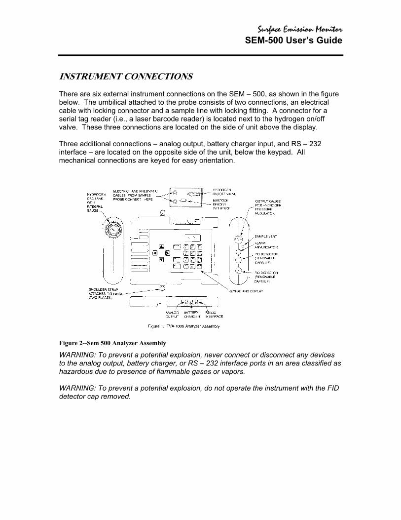
INSTRUMENT CONNECTIONS There are six external instrument connections on the SEM – 500, as shown in the figure below. The umbilical attached to the probe consists of two connections, an electrical cable with locking connector and a sample line with locking fitting. A connector for a serial tag reader (i.e., a laser barcode reader) is located next to the hydrogen on/off valve. These three connections are located on the side of unit above the display. Three additional connections – analog output, battery charger input, and RS – 232 interface – are located on the opposite side of the unit, below the keypad. All mechanical connections are keyed for easy orientation.
Figure 2--Sem 500 Analyzer Assembly WARNING: To prevent a potential explosion, never connect or disconnect any devices to the analog output, battery charger, or RS – 232 interface ports in an area classified as hazardous due to presence of flammable gases or vapors. WARNING: To prevent a potential explosion, do not operate the instrument with the FID detector cap removed.

SSuurrffaaccee EEmmiissssiioonn MMoonniittoorr SEM-500 User’s Guide
INSTRUMENT SIDEPACK DISPLAY The liquid crystal display (LCD) in the instrument sidepack, as shown in the figure that follows, has four 16-character lines for three types of displays (MENU, ENTRY, and RUN). In menu displays, the whole screen is normally dedicated to the menu. In entry displays, the screen provides prompts and instructions for inputting new data. The normal run display consists of the live measurement data on lines 1 and 2 and menu items on lines 3 and 4. Other display information appears as you page through various menus.
2= 4= y
In menu displays, the whole screen is normally dedicated to the menu.
U
In entry displays, the screen provides prompts and instructions for entering new data.
FTaPr
The normal run display consists of the live measurement data in Lines 1 and 2 and menu items on lines 3 and 4. Other display information appears as you page through various menus.
Main Menu 1=run
setup 3=infopclink/memor
Enter low ceil: Fid: 000.00ppm p/on = next unitEnter = accept
id: 2g: b ess
.50 ppm
ld _____char key

SSuurrffaaccee EEmmiissssiioonn MMoonniittoorr SEM-500 User’s Guide
INSTRUMENT SIDEPACK KEYPAD The keypad, as shown below, has 19 keys, some of which are dual function. When you press a key, the screen displays the selection. When you make a selection that creates or changes a parameter, you must then press the ENTER key. The left/right arrow keys move the character entry position. The up/down keys make page selections or switch from PPM, pp., or % to another reading. The following figure and table show the functions of all the keys.
Figure 3--Keypad NOTE: To activate OFF, CONTROL, EXIT, and ENTER functions, press and HOLD the key for approximately ½ second.
Key Function ON The ON key enables power from the battery to the instrument. OFF The OFF key disables power from the battery to the instrument. CONTROL The CONTROL key is multi-function and is used to turn the
pump, and FID on or off, and to ignite the FID. EXIT The EXIT key clears any entry made in error or bypasses
information that you do not want to change, and clears error or warning screens.
ENTER The ENTER key has three functions: Press ENTER if you have typed one or more characters and wish to keep that information. Press ENTER to respond to a menu question.
Left/Right Arrows The left and right arrow keys move character entry position. Up/Down Arrows The up and down arrow keys make page selections or scroll
through options in SETUP entry screens.

SSuurrffaaccee EEmmiissssiioonn MMoonniittoorr SEM-500 User’s Guide
Hardware
Key Function Alphanumeric The alphanumeric keys enable you to type letters or numbers
into various menus. If a display asks for a number only, simply press the desired key. Two steps are required to type an alphanumeric character. First, press the key with the desired letter or number. The screen then displays a selection prompt at the bottom in which 1 = first letter, 2 = second letter, 3 = third letter, and 0 = number. Press the appropriate key to execute the selection. Three uses: Select menu options Enter numbers, 0-9, using single keystroke Enter alphanumeric data, A-Z, 0-9, SPACE, using 2 keystrokes per character
Probe Connections The sample probe assembly is a hand-held device that enables you to take vapor samples at precise locations. It connects to the instrument by means of an umbilical. The umbilical has two quick-disconnect fasteners (one electrical, one sample line) at the instrument end. Use the slide-on connector, located at the forward end probe, to attach various sampling devices. The operator keypad and measurement display are also located on the handle, as shown in the following diagram.
Figure 4--Sample Probe Assembly
SSuurrffaaccee EEmmiissssiioonn MMoonniittoorr SEM-500 User’s Guide
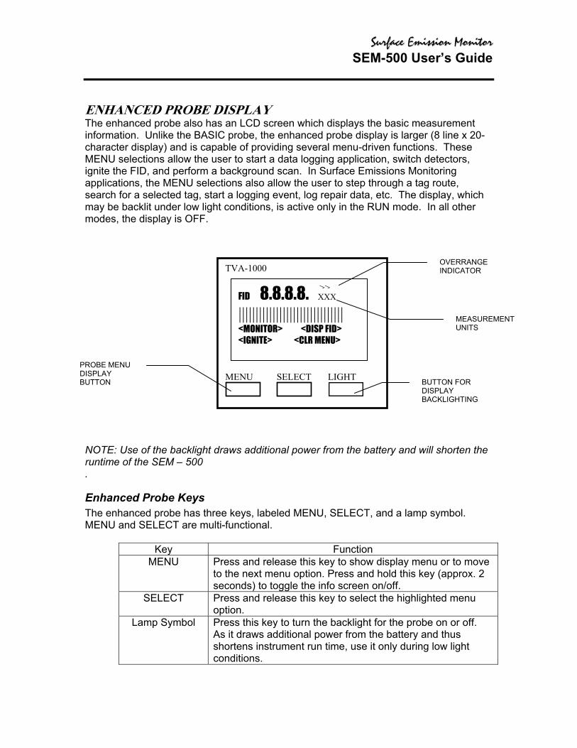
ENHANCED PROBE DISPLAY The enhanced probe also has an LCD screen which displays the basic measurement information. Unlike the BASIC probe, the enhanced probe display is larger (8 line x 20-character display) and is capable of providing several menu-driven functions. These MENU selections allow the user to start a data logging application, switch detectors, ignite the FID, and perform a background scan. In Surface Emissions Monitoring applications, the MENU selections also allow the user to step through a tag route, search for a selected tag, start a logging event, log repair data, etc. The display, which may be backlit under low light conditions, is active only in the RUN mode. In all other modes, the display is OFF.
NOTE: Use of the backlight draws additional poweruntime of the SEM – 500 .
Enhanced Probe Keys The enhanced probe has three keys, labeled MENMENU and SELECT are multi-functional.
Key MENU Press and release this
to the next menu optioseconds) to toggle the
SELECT Press and release thisoption.
Lamp Symbol Press this key to turn tAs it draws additional shortens instrument ruconditions.
PROBE MENU DISPLAY BUTTON
TVA-1000 MENU SELECT
FID 8.8.8.8. |||||||||||||||||||||||<MONITOR> <DI<IGNITE> <CLR
OVERRANGE INDICATOR
>
>
r from the battery and will shorten the
U, SELECT, and a lamp symbol.
Function key to show display menu or to move n. Press and hold this key (approx. 2 info screen on/off. key to select the highlighted menu
he backlight for the probe on or off. power from the battery and thus n time, use it only during low light
BUTTON FOR DISPLAY BACKLIGHTING
LIGHT
XXX
|||||||| SP FID> MENU>
MEASUREMENT UNITS

SSuurrffaaccee EEmmiissssiioonn MMoonniittoorr SEM-500 User’s Guide
DISPLAY MENUS
Main Menu Structure The display on the SEM-500 analyzer is a menu-driven device. The various menus prompt you to select or enter information. With various keystrokes, you can accomplish all necessary setup (configuration) and operational tasks.
2=4=
Whenever you turn on the SEM-500, the Main Menu screen display is the first usable display to appear. It contains selections that move you to all other menus. When you press the appropriate number key, as described below, the desired menu and the associated display or menu appears automatically. Menu Selection Function 1 = RUN Use this selection to assign tags to specific
view/log analysis of organic/inorganic comp2 = SETUP This menu contains configuration procedure
structure for performing calibrations, enterinsetting alarm levels, selecting log modes, enmultipliers and setting time/date.
3 = INFO This is a view-only menu structure that allowvarious information.
4 = PCLink/Memory Use this menu to download/upload informatpersonal computer, to perform a remote SEpersonal computer, or to clear memory.
Once you are familiar with the various menus and know where to enteinformation, you may want to use a short cut method of tracking the mThe following figure shows the complete menu structure for the SEM-5 Warning messages and meanings can be found in the Troubleshootinmanual (see “Warning Messages” on page 76).
MAIN MENU 1=RUN
SETUP 3=Info pclink/memory
surveys and to ounds. s and menu g ID numbers, tering response
s you to display
ion to/from a TUP from a
r specific enu structure. 00 Analyzer.
g section of this

SSuurrffaaccee EEmmiissssiioonn MMoonniittoorr SEM-500 User’s Guide
INSERT MATRIX RE: RUN/SETUP/INFO/PCLINK/MEMORY CHART

SSuurrffaaccee EEmmiissssiioonn MMoonniittoorr SEM-500 User’s Guide
PASSCODE PROTECT ON I The SEM-500 Setup Menu can be passcode protected. This option allows you to protect the setup parameters from anyone who is not familiar with your 6-digit passcode. If this feature is enabled, you need to enter your passcode each time you choose to display the SETUP menu. A selection in the SETUP menu entitled “Passcode” allows you to administer the passcode protection feature. From the SETUP menu, choose option #4 (Passcode). The SEM-500 will give you three choices:
1. New Passcode
This selection allows you to enter and/or change the 6-digit calibration passcode. You may use any characters from the alphanumeric keypad in your passcode. You must then verify the passcode to make sure you have entered it properly.
2. Enable
This selection allows you to activate the passcode protection feature. Once this feature is activated, you must enter your passcode whenever you request access to the SETUP menu. Once passcode protection has been enabled and you exit the SETUP menu, the option can only be disabled by entering the passcode to gain access to the SETUP menu again. REMEMBER YOUR PASSCODE! 3. Disable This selection allows you to deactivate the passcode protection feature. Once this feature is deactivated, you have unlimited access to the SETUP menu without entering a passcode. NOTE: In the event you inadvertently forget your passcode, contact CES/LANDTEC for assistance.

SSuurrffaaccee EEmmiissssiioonn MMoonniittoorr SEM-500 User’s Guide
CONTROL MENU The Control menu is used for turning the sampling pump on and off, turning FID on and off, and for initiating gas ignition of FID. The menu has three options: 1. Turn Pump ON/OFF 2. Turn FID ON/OFF 3. Ignite FID Selecting Option 1 toggles the pump on or off. Selecting Option 2 toggles the FID on and off. In the RUN mode, when the FID is off, dashes will appear instead of a reading and all FID alarms are overridden. Selecting Option 3 initiates the FID flame ignition sequence, which momentarily turns on the ignite coil and simultaneously turns off the pump. After running the initial startup diagnostic, the Control menu can be accessed at any time.
Setup Procedure Setup (configuration) of the SEM-500 is the most important step in obtaining accurate gas samples. During setup, you must set four parameters, as follows: 1. Calibration Setting 2. Alarm Levels 3. Date (year/month/day)(Set once only.) 4. Time of Day (Set once only.) NOTE: Time may be set only if the date is within the valid range of 1980 to 2037. You may also set the following parameters: 1. Log Methods 2. Type of Probe Display or Barcode Reader 3. Compound Names and Response Factors 4. Reader Type and Port Initialization (if used) 5. User Identification Number 6. Optional Settings (Calibration Passcode, Key Click, Display Delay, Calibration Mode) Each parameter is explained in detail in the following sections.

SSuurrffaaccee EEmmiissssiioonn MMoonniittoorr SEM-500 User’s Guide
CALIBRATION To provide the specified accuracy, the instrument must be calibrated at the beginning of each workday. To reach the CALIBRATION menu from the MAIN MENU, choose 2 =
Setup and 1 = Calib. When youfollowing selections:
1=C 3
5=
The steps involved in calibrating1. Configure the calibration var2. Define the span concentratio3. Zero the instrument using ei4. Calibrate the reference poin
configured for as many as n5. Optional: Set instrument res6. Optional: Take background NOTE: Prior to performing calibapproximately 30 minutes. Thethroughout the warm-up period.
Calibration MENU fg 2=SpanConc=Zero 4=Span RF 6=Backgnd
reach the CALIBRATION menu, you will see thethe SEM-500 are as follows: iables (Cfg). ns to be used (SpanConc).
ther a zero gas or clean ambient air (Zero). t(s) using known span gases. The SEM-500 can be ine (9) different span gas values (Span). ponse factors if necessary (RF).
reading (Backgnd).
ration, the instrument must be on and warmed up for pump must be ON, and the FID must be ignited

SSuurrffaaccee EEmmiissssiioonn MMoonniittoorr SEM-500 User’s Guide
Calibration Configuration Before you calibrate the SEM – 500 for the first time, you may want to customize certain calibration settings. Once you have configured these settings, you don’t need to set them again every time you calibrate unless you want to change one. In order to set your calibration options from the CALIBRATION menu, choose menu selection #1 (Cfg). This will produce the following CAL CONFIG MENUs which can be scrolled through by using the Up and Down arrows:
Backg This sedetectocorrecmeasuloggeddisplay
The sethis op NOTEis take Cal Ac This seacceptdisplay
Cal Config MENU 1 Number Span PT. 2 Backgnd Corrct
UP/DN=More
round Correct
lection allows you to choose r readings displayed and logg
tion, the last background readred reading. This corrected r. Choosing this selection from:
cond line of the display showtion by choosing any one of th
: A default background value on.
cept Mode
lection allows you to choose ed. Choosing this selection fr:
Cal Config MENU1=Accept Mode 2=Save Mode UP/DN More
whether or not apply backgroued in memory. If you choose
ing stored in memory will be seading will be the value displa
the CAL CONFIG MENU pro
s what option is currently selee menu selections.
f 0 is stored in memory until a
whether or not calibration will om the CAL CONFIG MENU
Cal Config MENU1=RF calc mode
UP/DN More
nd correction to the to apply background ubtracted from the yed and the value duces the following
Backgrnd Correct: Off
3=FID
cted. You can change
background reading
be automatically produces the following

SSuurrffaaccee EEmmiissssiioonn MMoonniittoorr SEM-500 User’s Guide
The second line of the display shows what option is currently selected. If “Manual” is chosen, the instrument will display the detector count during calibration and prompt the user to decide when to accept the calibration value. If “Auto” is chosen, the instrument will automatically determine the value to be stored and when to do it.
1=
Cal Save Mode This selection allows you to chosave an accepted calibration. Cproduces the following display: The second line of the display schosen, after a calibration valueto decide whether to save the caAgain?). If “Auto” is chosen, thecalibration value without prompt
Cal Accept Mode: Auto
Manual 2=Auto
ose whether or not the SEM – 500 will automatically hoosing this selection from the CAL CONFIG MENU
hows what option is currently selected. If “Manual” is has been accepted the instrument will prompt the user libration value or repeat the calibration (1 = Yes or 2 = instrument store will automatically store the accepted ing the user.
1=M
Cal Save Mode: Auto
anual 2=Auto
SSuurrffaaccee EEmmiissssiioonn MMoonniittoorr SEM-500 User’s Guide
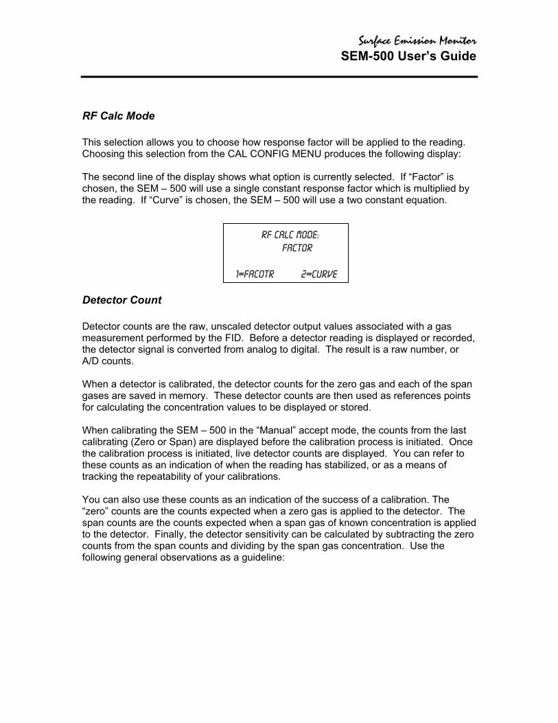
RF Calc Mode This selection allows you to choose how response factor will be applied to the reading. Choosing this selection from the CAL CONFIG MENU produces the following display: The second line of the display shows what option is currently selected. If “Factor” is chosen, the SEM – 500 will use a single constant response factor which is multiplied by the reading. If “Curve” is chosen, the SEM – 500 will use a two constant equation.
1=F
Detector Count Detector counts are the raw, unscaledmeasurement performed by the FID. the detector signal is converted from aA/D counts. When a detector is calibrated, the detgases are saved in memory. These dfor calculating the concentration value When calibrating the SEM – 500 in thcalibrating (Zero or Span) are displayethe calibration process is initiated, livethese counts as an indication of whentracking the repeatability of your calib You can also use these counts as an “zero” counts are the counts expectedspan counts are the counts expected to the detector. Finally, the detector scounts from the span counts and dividfollowing general observations as a g
RF calc Mode: Factor
acotr 2=Curve
detector output values associated with a gas Before a detector reading is displayed or recorded, nalog to digital. The result is a raw number, or
ector counts for the zero gas and each of the span etector counts are then used as references points s to be displayed or stored.
e “Manual” accept mode, the counts from the last d before the calibration process is initiated. Once detector counts are displayed. You can refer to the reading has stabilized, or as a means of rations.
indication of the success of a calibration. The when a zero gas is applied to the detector. The when a span gas of known concentration is applied ensitivity can be calculated by subtracting the zero ing by the span gas concentration. Use the
uideline:
SSuurrffaaccee EEmmiissssiioonn MMoonniittoorr SEM-500 User’s Guide
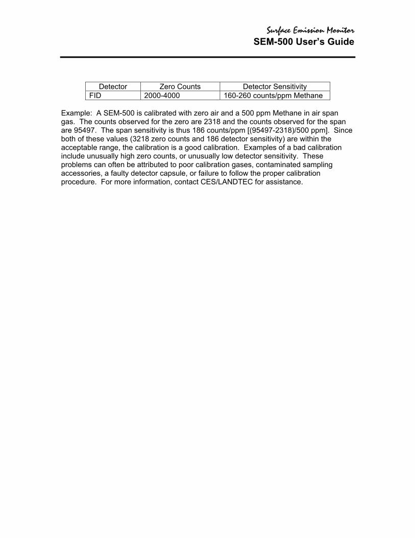
Detector Zero Counts Detector Sensitivity
FID 2000-4000 160-260 counts/ppm Methane Example: A SEM-500 is calibrated with zero air and a 500 ppm Methane in air span gas. The counts observed for the zero are 2318 and the counts observed for the span are 95497. The span sensitivity is thus 186 counts/ppm [(95497-2318)/500 ppm]. Since both of these values (3218 zero counts and 186 detector sensitivity) are within the acceptable range, the calibration is a good calibration. Examples of a bad calibration include unusually high zero counts, or unusually low detector sensitivity. These problems can often be attributed to poor calibration gases, contaminated sampling accessories, a faulty detector capsule, or failure to follow the proper calibration procedure. For more information, contact CES/LANDTEC for assistance.

SSuurrffaaccee EEmmiissssiioonn MMoonniittoorr SEM-500 User’s Guide
Defining the Span Gas Concentration(s) NOTES:
The span gas concentration is the known concentration of the gas standards used to calibrate your SEM-500. Methane in air is the recommended calibration standard for the FID. Other gases may be used if desired.
If your instrument is configured for multiple span points, be sure to set the concentration for ALL span points.
1. From the CALIBRATION menu display, press 2=SpanConc. The upper display will
display the concentration value of your span gas (expressed as ppb, ppm or %) as of the last calibration:
If the SEM-500 is configured for mvalues for Point #1 will be displayscroll through the span gas conce
2. To change a span gas concen
appear:
FID: 500 PPM
Span Gas Concent Enter=New conc
ultiple calibration points, the span gas concentration ed. The Up and Down arrow keys can be used to ntration values for other points:
FID: 500 PPMSpan Pt1(Up/Dn) Enter=New conc
tration value, press ENTER. The following display will
Enter Span Conc:FID: 000000 ppmUp/Dn=Next Unit Enter=Accept

SSuurrffaaccee EEmmiissssiioonn MMoonniittoorr SEM-500 User’s Guide
Use the up and down arrow keys to select the measurement units (%, ppm, or ppb) and the decimal point position. There are 5 selections to choose from:
Range Display Units 5 DD.DD % 4 DDDDDD ppm 3 DDDD.D ppm 2 DDD.DD ppm 1 DDDDDD ppb
The range of the instrument is determined by your selection of measurement units and decimal point placement. In the run mode, the instrument will auto range upward only to select the optimum range for displaying measurement information. For example, if you entered a value in Range 3 and the measured value changes to a high value, the instrument will automatically switch to range 4. If it increases further, it will switch to Range 5. Auto-ranging will not switch ranges beyond the span gas range in the downward direction. After you have selected the measurement units and decimal point placement, use the keypad to enter the concentration value. Press ENTER to accept this value and store it in the SEM’s memory. 3. If your SEM-500 is configured for more than one span point, you may use the Up/Dn
arrow keys to select the next span point and repeat the procedure. 4. When the last gas concentration value has been entered, you can return to the
CALIBRATION menu, by pressing the EXIT key.

SSuurrffaaccee EEmmiissssiioonn MMoonniittoorr SEM-500 User’s Guide
Zero Reference Point Calibration From the CALIBRATION menu display, press 3=Zero. 1. The following sequence shows the procedure when the SEM – 500 is
configured with both Cal Accept mode and Cal Save mode = Auto. If either mode is Manual, an extra confirmation is required at the appropriate step.
If you press 3=Zero, the display will show:
FID: 0
Zero Cal: Enter=Start
2. To perform the actual ZERO procedure for an FID - Press ENTER
FID 0
Zero Gas Exit=Cancel
3. Apply the zero gas to the probe at ambient pressure (using a clean labeled
gas sampling bag) and then press ENTER. The instrument analyzes the zero sample.
Apply Zero Gas FID
Enter=Start Exit=Cancel
The ACCEPTED message appears for a short time and is then replaced by the normal CALIBRATION menu. When the ACCEPTED message disappears and the CALIBRATION menu appears, the ZERO reference value is stored. This value is stored in non-volatile memory until the next calibration is performed. The date and time of this calibration are stored and can be accessed through the INFO menu. NOTE: For optimum accuracy, re-zero the FID every time the hydrogen supply valve is turned on.

SSuurrffaaccee EEmmiissssiioonn MMoonniittoorr SEM-500 User’s Guide
Span Reference Point(s) Calibration To set the span reference point, execute the procedure described below. Note that the procedure is the same as that for setting the zero reference except that a span gas is used instead of a zero gas. The procedure is: From the CALIBRATION MENU display, press 4=Span. 1. The following sequence shows the procedure when the SEM – 500 is
configured with both Cal mode and Cal Save mode = Auto. If either mode is Manual, an extra confirmation is required at the appropriate step.
2. If multiple span points are used, repeat the following procedure for each and every span point.
When you press 4=Span, the display will show: INSERT FID SCREEN MENU
If more than one reference span gas concentration has been configured, pressing the Up/Dn keys will allow you to scroll through all defined reference gas concentration points.
3. To perform the actual SPAN calibration (for example at 500 ppm): INSERT FID SCREEN MENU Press ENTER 4. Apply the appropriate span gas to the probe at ambient pressure (using a
clean and labeled gas sampling bag) and then press ENTER.
INSERT FID SCREEN MENU
The instrument analyzes the span sample. INSERT FID SCREEN MENU
When only one reference span gas concentration is used, the ACCEPTED message appears for a short time and is then replaced by the normal CALIBRATION menu. When the ACCEPTED message disappears and the CALIBRATION menu Appears, the SPAN reference value is stored. This value is stored in non-volatile memory until the next calibration is performed. The date and time of this calibration are stored and can be accessed through the INFO menu.
5. If more than one reference span gas concentration had been defined, the span calibration display returns. Move to the next concentration point (Up/Dn keys) and repeat steps 2-3 above until each reference gas concentration point has been calibrated.

SSuurrffaaccee EEmmiissssiioonn MMoonniittoorr SEM-500 User’s Guide
The RUN mode displays (as governed by the LOG selection) are: NONE AUTO, VOC, or F.E. INSERT NONE SCREEN INSERT SCREEN or NOTE: To display and change the log menu, the instrument must be ON but does not have to be warmed up.
Defining the Response Factor Although the FID is calibrated with span gases of known concentration (usually Methane), the detector responds to many different compounds with differing levels of sensitivity. In order to adjust the analyzer reading from “ppm of Methane” to ppm of the compound of interest, a correction factor must be applied to the reading. This correction factor is also known as a Response Factor. You can choose from up to nine (9) user-defined response factors, or use the default response factor of 1.00. Each response factor can be assigned a 9-character alphanumeric name. The SEM – 500 Uses one of two different response factor formats: a Multiplier or a Curve. The top line shows the currently active response factor. If no response factor is applied, the currently active response factor will be the factory DEFAULT (1.00 for PID isobutylene). The name and value of the default response factor cannot be zero.
RFO: Default Up/Dn=Next RF
Enter=Accept
SSuurrffaaccee EEmmiissssiioonn MMoonniittoorr SEM-500 User’s Guide
HARDWARE CONFIGURATION
Barcode Reader/Probe Display NOTE: To select a barcode reader or probe display, the instrument must be ON but does not have to be warmed up. The SEM – 500 must be configured to operate with the appropriate barcode reader and probe display. To select which accessories to use: 1. From the MAIN menu display, press 2 = Setup. 2. From the SETUP menu display, press 5 = Hardware.
The Hardware menu will appear: INSERT HARDWARE SCREEN
To select probe display: 1. From the HARDWARE menu, choose 1 = Probe display. The PROBE DISPLAY
menu will appear: INSERT PROBE MENU 2. The second line of the display shows the currently configured display type. To
choose the basic probe display, press 1. To choose the Enhanced SEM probe display, press 2.
To select a barcode reader: 1. From the HARDWARE menu, choose 2 = Barcode reader. The BARCODE
menu will appear: INSERT BARCODE MENU 2. The second line of the display show the currently configured barcode scanner
type. To select a reader, press 1. The BARCODE READERS menu will appear. INSERT BARCODE READERS MENU 3. To choose no reader, press 1. To choose the HP Smart Wand, press 2. To
choose the PSC laser scanner, press 3. 4. To initialize a reader, ensure that the reader is plugged into the 9-pin reader port
and securely fastened in place. From the BARCODE menu screen, press ENTER=Initialize. The message “Barcode reader initialization in progress” will appear. A successful initialization will result in an “Initialization Complete” message. If the reader is not properly connected or if an incorrect model is connected, a “WARNING: Barcode reader not found” message will appear.
WARNING: Not all readers are approved for user in areas classified as hazardous due to the presence of flammable gases or vapors. Contact CES/LANDTEC for more information.

SSuurrffaaccee EEmmiissssiioonn MMoonniittoorr SEM-500 User’s Guide
User Identification Number NOTE: To set the User ID number, the instrument must be ON but does not have to be warmed up. 1. From the MAIN menu display, press 2=Setup. 2. From the SETUP menu display, press 6=Othr. 3. From the OTHER SETTINGS menu display, press 1=User ID. 4. From the User ID prompt, press ENTER. 5. Use the keypad to type your user ID. 6. Press ENTER to store the user ID into memory.
Date
NOTE: To set the correct date, the instrument must be ON but does not have to be warmed up. Date entries earlier than Jan. 1, 1980 or no later than 2037 are invalid. 1. From the MAIN menu display, press 2=Setup. 2. From the SETUP menu display, press 6=Othr. 3. From the OTHER SETTINGS menu, press 2=Date. 4. The next screen reads the current date. If OK, press EXIT or ENTER to change.
EXIT returns to the OTHER SETTINGS menu. ENTER prompts you to type.the correct date. Do so by typing month/day/year, and then press ENTER to store the date in memory. The display then returns to OTHER SETTINGS.
Time of Day NOTE: To set the correct time, the instrument must be ON but does not have to be warmed up. The date must be within the valid range of 1980 to 2037. 1. From the MAIN menu display, press 2=Setup. 2. From the SETUP menu display, press 6=Othr. 3. From the OTHER SETTINGS Menu, press 3=Time. 4. The next screen reads the current time. If it is OK, press EXIT or ENTER to change.
EXIT returns to the OTHER SETTING Menu, ENTER prompts you to type the correct time. Do so by typing hour/minute/second. Then press ENTER to store the time in memory. The display then returns to OTHER SETTINGS.

SSuurrffaaccee EEmmiissssiioonn MMoonniittoorr SEM-500 User’s Guide
USER Options Key Click If the key click is on, a chirp is heard every time a key is pressed. NOTE: To select key click on/off, the instrument must be ON but does not have to be warmed up.
1. From the MAIN MENU display, press 2=Setup. 2. From the SETUP MENU display, press 6=Othr. 3. From the OTHER SETTINGS Menu, press 4= User Options. 4. From the USER OPTIONS Menu, press 1=Key Click. 5. From the Key click Menu, press 1=On or 2=Off. The screen displays the previous
selection. When a new selection is made, the display returns to USER OPTIONS.
Display Delay This function determines the length of time that temporary messages remain on the screen. NOTE: To select the display delay, the instrument must be ON but does not have to be warmed up. 1. From the MAIN menu display, press 2=Setup. 2. From the SETUP menu display, press 6=Othr. 3. From the OTHER SETTINGS menu, press 4=User Options. 4. From the USER OPTIONS menu, Press 2=Display Delay. 5. From the Display Delay menu, press 1=Short, 2=Medium or 3=Long. The screen
displays the previous selection. When a new selection is made, the display returns to USER OPTIONS.
NOTE: “Short” is approximately 0.5 sec, “Medium” is approximately 1.5 seconds, and “Long” is approximately 3.5 seconds.

SSuurrffaaccee EEmmiissssiioonn MMoonniittoorr SEM-500 User’s Guide
INFORMATION MENU The information menu is a view-only list of 14 items/parameters existing in the instrument. No changes may be made in this menu. Enter the INFO Menu from the MAIN menu by pressing 3 = Info. Use the up/down keys to page through the list. The parameters/items you may view are:
♦ Model: SEM-500 ♦ S/N DDDDDDDDDDDD ♦ Date ♦ Time ♦ Memory: how much is free to use ♦ Reader: Serial reader is found or not found ♦ Ver: Current Software Version No. ♦ FID span calibration: Date and time of last calibration ♦ FID zero calibration: Date and time of last calibration ♦ Det: FID ♦ Pump: On or Off ♦ Bat: Battery voltage listed, OK or low
NOTE: To view calibration information, you must return to the calibration menu in SETUP. Press EXIT to return to MAIN menu.

SSuurrffaaccee EEmmiissssiioonn MMoonniittoorr SEM-500 User’s Guide
PC LINK/MEMORY WARNING: The RS-232 port is not approved for use in areas classified as hazardous due to the presence of flammable gases or vapors. This menu allows you to link the SEM-500 to a personal computer (PC) through the RS-232 communications port or to clear existing route or log memory within the instrument.

SSuurrffaaccee EEmmiissssiioonn MMoonniittoorr SEM-500 User’s Guide
USING THE ENHANCED PROBE This probe/display allows you to perform menu-driven operational/datalogging functions from the handheld unit and reduces the need to access the sidepack keypad. NOTE: In order to use the Enhanced Probe, be sure that the HARDWARE setting in the SEM – 500 SETUP menu is properly configured. There are three buttons on the Enhanced Probe which allow you to interact with the SEM – 500:
♦ MENU – Used to cause the menu to appear on the bottom of the probe display and to step through the available selection
♦ SELECT – Used to choose the currently highlighted menu selection; e.g., “LOG”. ♦ Light Bulb Icon – Used to turn the display backlight on and off
1. From the MAIN menu, press 1 = RUN. 2. The enhanced probe display will display the detector reading (FID or PID) at the top
and an analog bargraph on the bottom. Press the MENU key on the Enhanced Probe Display to show the Opening menu: INSERT OPENING MENU
The highlighted menu item is the item surrounded by brackets. Pressing the MENU key will cause the brackets to move from menu item to menu item. When you reach the menu item you wish to choose, press SELECT. The Opening menu items are as follows:
Menu Item Function Enter logging mode Enters FE, or Auto logging mode, allowing you to enter tags,
toggle through route files, log data, etc. If no logging is selected in the SETUP menu, then this selection does not appear.
Ignite Ignites FID. Background Records a new background reading. Exit Clears the menu and returns to the Bargraph display.
Auto Logging with the Enhanced Probe 1. In the RUN mode, press the MENU key to cause the menu to appear. Select “Enter
logging mode.” 2. Use the sidepack or barcode reader to enter a tag, or simply select “Accept” to enter
a blank tag. 3. Choose “Start log sampling” to begin Auto logging. 4. The Enhanced probe will display the countdown and continue to log until EXIT is
selected at the probe or the sidepack keypad. 5. Once EXIT is selected, you may enter another tag and begin logging again or exit
from the RUN mode.

SSuurrffaaccee EEmmiissssiioonn MMoonniittoorr SEM-500 User’s Guide
FE (Fugitive Emissions) Logging with the Enhanced Probe In FE Logging you follow a preconfigured route list consisting of component records for equipment to be monitored. You should first download a route to the SEM – 500’s memory before entering the RUN mode. In the RUN mode, press the MENU key to cause the menu to appear. Select “Enter logging mode.” The following display will appear on the Enhanced probe:
INSERT ENTER LOGGING SCREEN In addition to the concentration display at the top, the FE mode shows several fields which have been in by the download route. The SEM – 500 starts at the first record in the route and displays the component tag number (Tag), equipment type (Eqp), equipment size (Size), and leak definition (Max). If a reading has already been logged into memory for this record, it will also be displayed followed by the words “LastLog.”
Navigating the Route File Selecting “Next” from the first logging mode screen will allow you to step to the next record in the route. Selecting “Prev” will allow you to step to the previous record in the route. You can also enter a tag via the keypad and the SEM – 500 will automatically skip to that tag if it is contained within the route. If the tag is not contained within the route, a “TAG NOT FOUND” message will appear and you will be given the option to “Insert” that tag into the route or “Exit.”
Logging Data Once you have reached the correct tag for the component you wish to monitor, you may select “Start log sampling” to begin recording data. The SEM – 500 will display the readings from both detectors and begin counting down for the time interval selected in the SETUP menu. The countdown is shown on the last line of the display: INSERT LOGGING DATA SCREEN Once the countdown is complete, the SEM – 500 display will freeze on the reading to be logged and indicate if it is a leak (i.e., if the reading of the active detector exceeds the indicated leak rate). You will be given several options: INSERT SCREEN
If you choose “Sav”, the SEM – 500 will be store the reading in memory (replacing any previous logged readings for that Tag) and proceed to the next component record in the route. If you choose “Again” the SEM – 500 will repeat the countdown and obtain a new reading. If you choose “Exit” the SEM – 500 will return to the previous screen.

SSuurrffaaccee EEmmiissssiioonn MMoonniittoorr SEM-500 User’s Guide
Repair Menus If the reading during the logging interval exceeds the leak definition, the SEM – 500 will indicate that it is a leak by printing “Leaker!” If you wish, you may record what part of the component is leaking and what action was taken as a first attempt at repair. Choose “Repair” instead of “Sav” and the SEM – 500 will proceed to the repair menus: INSERT SCREEN The two lines below the reading show the currently selected leak source and repair method. Choosing “Select leak source” will allow you to record what part of the component is leaking by choosing from a list of leak sources (Valve Bonnet, Compressor Seal, Downstream Flange, Valve Packing, Pump Seal, Upstream Flange). Choosing “Select repair method” will allow you to record what method was used for the first attempt at repair (Place Cap, Gun Pack Valve, Place Plug, Repack Valve, Replace Gasket, Replace, Seal Job, Steam Seal, Tighten Bonnet, Tighten Cap, Tighten Flange, Tighten Packing, Tighten Plug, Wash Seal). Choosing “Exit” will return you to the previous display. If you choose a leak source and repair menu, be sure to select “Sav” when you return to this menu so the reading and repair information will be saved in memory before proceeding to the next component record.
Additional Component Information Displays containing additional information about the component and the SEM – 500 status are available from the handheld unit. If you press and hold the MENU key for approximately 2 seconds, the Enhanced display will present an INFO page: INSERT SCREEN The INFO page overwrites the bottom four lines of the record with other fields such as Location (Loc) and Description (the two lines below the location). The Location field contains the Area and the Subarea where component is located. The Description field displays up to 40 characters of additional information about the component. Selecting “Pg” at the bottom of the display will step you through other INFO, pages containing information such as Run ID, Record number, number of points logged, number of leakers found, number of repairs performed, pump status, free memory, barcode reader status, etc. Selecting “Exit” will return you back to the normal component record.

SSuurrffaaccee EEmmiissssiioonn MMoonniittoorr SEM-500 User’s Guide
MAINTENANCE
Removable, Renewable Parts WARNING: Parts replacement and maintenance should not be performed in areas classified as hazardous due to presence of flammable gases or vapors. Opening of the analyzer is not recommended under any circumstances, due to the intrinsic safety rating of the analyzer. Violation of this policy could void the warranty of this product. (Extended Service Plans are available; contact CES/LANDTEC Authorized Service for further information.) CES/LANDTEC suggests that you return the entire instrument to the factory or an authorized service center once a year for cleaning, testing, and calibration. Opening the SEM – 500 instrument case could void the warranty. From time to time, you must remove and renew several components of the SEM – 500 analyzer. Some components may be replaced as normal maintenance functions performed by operating personnel. Other components, however, should be replaced only by personnel thoroughly trained and familiar with the analyzer instrument and its applications. The components that may be maintained or replaced by operating personnel as part of normal operations are: 1. Battery – you may charge the battery in or out of the instrument or replace it with a
charged battery. 2. Hydrogen Tank – remove the tank to refill it. 3. FID Cartridge – remove and clean frequently. Replace when needed. 4. Close Area Sampler – replace if probe tip is clogged or damaged. 5. Filter Cups – (in the sampler assembly ans sidepack assembly) – clean/replace
frequently. 6. Optional Water Trap – replace membrane or membrane support if worn or damaged. 7. Sample Line Tubing – replace when dirty. 8. Sample Line Fitting – replace if damaged. 9. FID End Cap and Flame Arrestor – remove and clean frequently. Replace when
required. 10. FID Cavity – clean periodically. WARNING: Never change an electrical component in an area classified as hazardous due to a presence of flammable gases or vapors.

SSuurrffaaccee EEmmiissssiioonn MMoonniittoorr SEM-500 User’s Guide
NORMAL OPERATING MAINTENANCE The items described in this section may be performed as normal operating procedures.
Battery and Battery Charger WARNING: Do not remove or install batteries and do not use the battery charger in any area classified as hazardous due to the presence of flammable gases or vapors. The nickel cadmium battery, supplied with the unit, lasts for a minimum of eight hours of continuous use at 20°C. Extreme heat or cold and/or use of the backlight, however, will shorten that time. A battery charger with cable is shipped with the instrument. You do not have to remove the battery for charging. Simply plug the output of the charger into the mating connector marked CHRG in the instrument. Then, insert the charger plug into the appropriate wall outlet. A green power indicator is ON when the charger is operating. A yellow indicator is activated when the charger is connected to the instrument and the instrument is ON. Normal charge time for a fully discharged battery is approximately 16 hours, to two hours of charge for every hour of use.
Indicator Light Condition Indication
Green ON Charger is plugged in and operating. Green OFF Charger is not plugged in. YELLOW ON Charger is connected on the SEM – 500 and the
SEM – 500 is ON while the charger is operating (i.e., trickle charging).
Do not leave the battery on charge for extended periods (greater than 96 hours). If you wish to remove the battery from the SEM – 500 for charging or swapping with a spare battery, turn the instrument off. Using the special tool supplied with the accessory kit, unscrew the screw on the battery compartment cover on the rear of the instrument and remove the battery cover. As the battery pack fits snugly in the instrument housing, use care in removing the battery pack and its internal connector. As you remove the battery pack, note location of the battery connector. When re-inserting the battery pack in the instrument, be sure to push the connector into the same location, so that it does not interfere with placement of the battery pack. To charge the battery outside of the unit, use the adapter supplied in the accessory kit.

SSuurrffaaccee EEmmiissssiioonn MMoonniittoorr SEM-500 User’s Guide
Hydrogen Gas Tank FID instruments are supplied with an 85cc hydrogen gas tank. This tank, which may be pressurized to 2200 psi maximum at 25°C, will provide 8 hours operation when fully charged. The tank has an integrally mounted high pressure gauge that can be easily read when the tank is in or out of the instrument. Install the tank in the instrument by inserting it into the receptacle on the left side and tightening (left hand threads, tightening counterclockwise) until the rubber tank boot is flush with the instrument sidepack and a slight resistance is felt. Do not overtighten.
Fuel Refilling Procedure WARNING: A safe refill operation means there are no hydrogen leaks. Before any valves are opened, use a wrench to firmly tighten connections to the hydrogen supply tanks and the tank fill adapter. If escaping hydrogen is heard during the filling operation, close all valves and correct the leak before proceeding. Leak test with soapy water or equivalent. NOTES: 1. Use prepurified ZERO grade hydrogen (certified total hydrocarbons as methane <0.5
ppm recommended). 2. The hydrogen filling assembly contains a flow-limiting safety device. Approximately
two minutes are required to fill the tank. CAUTION: Do not fill hydrogen tank to a pressure greater than 15.2 MPa (2200 psig).
Precautions in Handling and Storage The major hazard associated with the handling of hydrogen is flammability. The following specific rules apply when handling hydrogen: 1. Never use cylinders of hydrogen in areas where flames, excessive heat, or sparks
may occur. 2. Use only explosion-proof equipment and spark-proof tools in areas where hydrogen
is handled. 3. Ground all equipment and lines used with hydrogen. 4. Never use a flame to detect hydrogen leaks – use soapy water. 5. Do not store reserve stocks of hydrogen with cylinders containing oxygen or other
highly oxidizing or combustible materials. 6. Store hydrogen tanks in a well-ventilated area. 7. Follow all regulatory safety and labeling precautions when shipping hydrogen in the
SEM – 500.
SSuurrffaaccee EEmmiissssiioonn MMoonniittoorr SEM-500 User’s Guide
NOTE: A bleeder assembly is provided in the tool kit to allow the hydrogen tank to be emptied for common carrier shipment. To use the bleeder, manually screw the bleeder onto the tank valve and allow the hydrogen to vent. This process will take about two minutes to complete. CAUTION: Observe all hydrogen handling procedures listed above. When transporting the instrument, remove the hydrogen tank and place it in its normal location in the carrying case. To fill the tank, use the following procedure: NOTE: All hydrogen fittings are left hand thread – do not overtighten. 1. Turn supply tank valve OFF. 2. Attach tank fill adapter to supply tank with valve OFF and with manifold valve on OFF
position. 3. Attach SEM – 500 hydrogen tank to tank fill adapter. (Note left hand thread – do not
overtighten.) 4. Open supply tank valve. Move fill adapter valve to FILL position. 5. Wait for SEM – 500 tank to fill. This may take 2 to 3 minutes because of flow
restrictors in the tank and fill adapter. 6. Close fill adapter valve. 7. Remove SEM – 500 tank. 8. Close supply tank valve. 9. Remove tank fill adapter. Always remove the tank from the instrument before storing in the instrument carrying case.

SSuurrffaaccee EEmmiissssiioonn MMoonniittoorr SEM-500 User’s Guide
Servicing an FID Cartridge To remove the FID cartridge, use the following procedure; 1. Close the hydrogen supply valve on the side of the instrument. Turn the instrument
off. 2. Using the special spanner wrench provided with the instrument tool kit, unscrew the
red cap holding the FID cartridge in place. 3. Screw the special extractor tool provided with the accessory kit into the off-center
hole in the cartridge (see Figure 10). 4. Remove the cartridge by pulling on the extractor. Unscrew the extractor from the
cartridge. Clean or replace the cartridge. 5. To insert a new cartridge, reverse the procedure. Note that a FID cartridge is
marked with a red band. To clean an FID cartridge, you will need a cotton swab and some isopropyl alcohol. Dip the swab into the isopropyl alcohol and insert it into the center of the cartridge. Swab the surface until clean and discard the swab. Take care not to touch the igniter coil, which is located close to the end of the capsule opposite the threaded hole used to remove capsule. Then dry the cartridge in an oven at 45°C to 55°C for one hour. When dry, re-insert the cartridge into the instrument, reversing the removal procedure. Do NOT overtighten cap. CAUTION: Do not allow any contact with the igniter coil during cleaning.
Cleaning the FID Detector Cap To clean the FID detector end cap, use the following procedure: 1. Close the hydrogen supply valve on the side of the instrument and turn off the power. 2. Using the special spanner wrench provided with the tool kit, unscrew and remove the
FID red detector cap. 3. Clean the cap using the isopropyl alcohol followed with a deionized or distilled water
rinse. Blow out carefully with compressed dry air. 4. Replace the cap.
SSuurrffaaccee EEmmiissssiioonn MMoonniittoorr SEM-500 User’s Guide
Replacing the Flame Arrestor The flame arrestor, located in the center of the red FID end cap, can be either cleaned or replaced. To replace the flame arrestor, use the following procedure: 1. Close the hydrogen supply valve on the side of the instrument and turn off the power. 2. Using the special spanner wrench provided with the tool kit, unscrew and remove the
FID red detector cap. 3. Remove spring. 4. Place the detector cap on a flat surface, face up. 5. Place a screwdriver through the center hole of the end cap, resting on the flame
arrestor. 6. Strike the end of the screwdriver with a hammer to drive the old flame arrestor out of
the end cap. 7. Remove the old flame arrestor. 8. Turn the end cap over so the red outer surface lies flat and the gray surface faces
up. 9. Place the new flame arrestor in the center hole. 10. Place a screwdriver on the newly installed flamed arrestor. 11. Strike the end of the screwdriver with a hammer to secure the new flame arrestor in
place. 12. Replace the spring. 13. Replace the detector cap on the unit.
Cleaning the FID Detector Cavities 1. Close the hydrogen supply valve on the side of the instrument. Turn the instrument
off. 2. Using the special spanner wrench provided with the tool kit, unscrew the cap holding
the respective detector cap. 3. Using the special extractor tool provided with the tool kit, screw the extractor into the
cartridge. 4. Remove the cartridge by pulling on the extractor. Unscrew the extractor from the
cartridge. 5. Carefully clean the inside of the detector cavity using a cotton swab and isopropyl
alcohol. Be sure to clean the high voltage contacts along the side of the cavity. Be especially careful around the detector signal collector probe at the rear of the cavity (and the thermocouple probe in the FID).
6. Dry the inside of the cavity using a low heat gun. 7. Insert the cartridge by reversing the procedure. Note that the cartridge must be
rotated to properly locate the key tabs.
SSuurrffaaccee EEmmiissssiioonn MMoonniittoorr SEM-500 User’s Guide
Cleaning or Replacing a Sintered Metal Filter To remove the sintered metal filter cup from the close area sampling, simply unscrew the cap from the sampler and tip the assembly so that the filter falls out. The same filter cup and spring are also located behind the sample line quick connect at the sidepack assembly. To remove, unscrew the quick connect so that the filter falls out. The internal spring will not fall out. You may clean the filter by immersing it in isopropyl alcohol or equivalent solvent and/or swabbing the surface with a Q-tip or cotton swab. After thoroughly cleaning the surface of the filter, place the filter in an oven and dry it at 40 °C to 55 °C for one hour. You can then reinsert the filter into the sampling assembly (with the closed end of the filter in first) and screw in the cap.
Replacing Sample Line To replace the sample line, execute the following procedure: 1. Loosen the probe nut and remove the sampling assembly by pulling it free from the
probe assembly. 2. Insert a thin rod through the hole in the side of the probe-fitting adapter. You will use
this rod to pull the adapter and tubing from the probe assembly. 3. Remove the tubing from the quick-connect fitting by pressing firmly on the ring at the
back of the fitting (a tool may be necessary) while pulling on the tubing. 4. At the base of the probe handle, gently push the tubing into the probe. At the same
time, use the rod to pull the probe fitting adapter and tubing forward from the probe assembly. When the adapter fitting is fully exposed, cut the tubing from the fitting and pull the remainder of the tubing back through the probe assembly until it is completely out of the probe.
5. Cut a new piece of tubing about three inches longer than the old tubing. 6. Insert new tubing through the bottom protective covering (where you connect to the
analyzer,) and slowly feed the tubing through toward readout handle. 7. Once the tubing exits the top protective covering, insert the new tubing into the probe
handle and carefully push it through to the other end. When the tubing is in position, cut the end square and push it over the barbed adapter fitting. (Heating the tube end may aid in fitting the tubing over the adapter.)
8. Grasp the tubing below the probe assembly handle and pull it back through the probe assembly until the adapter fitting is properly seated in the probe assembly.
9. Cut the other end of the tubing to the proper length and insert it into the end of the quick-connect fitting. (Allow 5/8-inch of tubing inside the fitting.)
SSuurrffaaccee EEmmiissssiioonn MMoonniittoorr SEM-500 User’s Guide
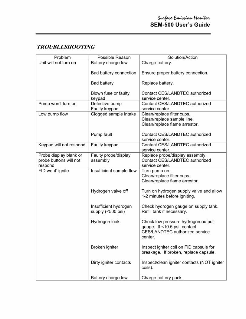
TROUBLESHOOTING
Problem Possible Reason Solution/Action Unit will not turn on
Battery charge low Bad battery connection Bad battery Blown fuse or faulty keypad
Charge battery. Ensure proper battery connection. Replace battery. Contact CES/LANDTEC authorized service center.
Pump won’t turn on Defective pump Faulty keypad
Contact CES/LANDTEC authorized service center.
Low pump flow Clogged sample intake Pump fault
Clean/replace filter cups. Clean/replace sample line. Clean/replace flame arrestor. Contact CES/LANDTEC authorized service center.
Keypad will not respond Faulty keypad Contact CES/LANDTEC authorized service center.
Probe display blank or probe buttons will not respond
Faulty probe/display assembly
Replace probe/display assembly. Contact CES/LANDTEC authorized service center.
FID wont’ ignite Insufficient sample flow Hydrogen valve off Insufficient hydrogen supply (<500 psi) Hydrogen leak Broken igniter Dirty igniter contacts Battery charge low
Turn pump on. Clean/replace filter cups. Clean/replace flame arrestor. Turn on hydrogen supply valve and allow 1-2 minutes before igniting. Check hydrogen gauge on supply tank. Refill tank if necessary. Check low pressure hydrogen output gauge. If <10.5 psi, contact CES/LANDTEC authorized service center. Inspect igniter coil on FID capsule for breakage. If broken, replace capsule. Inspect/clean igniter contacts (NOT igniter coils). Charge battery pack.

SSuurrffaaccee EEmmiissssiioonn MMoonniittoorr SEM-500 User’s Guide
Problem Possible Reason Solution/Action
FID noisy Water/contamination in the detector chamber Erratic pump flow Bad calibration
Clean/replace FID capsule and flame arrestor. Clean/replace filter cups. Clean/replace flame arrestor. Ensure proper calibration.
Unable to calibrate FID FID flame out Span concentration not properly set CAL gases contaminated Sample line/filter cups contaminated FID capsule contaminated or faulty Contaminated hydrogen tank Internal detector fault or contamination
Ignite FID. Input correct span gas concentration at CAL menu. Use clean gases and sampling equipment. Clean/replace sample line. Clean/replace filter cups. Clean/replace FID capsule. Replace hydrogen tank. Contact CES/LANDTEC authorized service center.
Excessive hydrogen consumption (<8 hours of run time for 2200 psi hydrogen)
Insufficient hydrogen pressure Leaking hydrogen tank Internal hydrogen leak
Refill tank. Replace tank. Contact CES/LANDTEC authorized service center.
Flameout problems Sample hydrocarbon content too high Insufficient oxygen in the sample (<14%) FID capsule contamination Insufficient sample flow
Use dilutor kit to achieve concentration within the dynamic range of the SEM. Use dilutor kit to dilute sample with air containing sufficient oxygen. Use PID for measurements. Clean/replace FID capsule. Clean/replace filter cups. Clean/replace flame arrestor.

SSuurrffaaccee EEmmiissssiioonn MMoonniittoorr SEM-500 User’s Guide
Moisture at FID flame arrestor NOTE: Normal operation produces some moisture. If performance is affected, attempt these solutions.
Insufficient sample flow Insufficient warm-up time
Clean/replace filter cups. Clean/replace flame arrestor. Allow 15 – 20 minutes warm-up.
SSuurrffaaccee EEmmiissssiioonn MMoonniittoorr SEM-500 User’s Guide
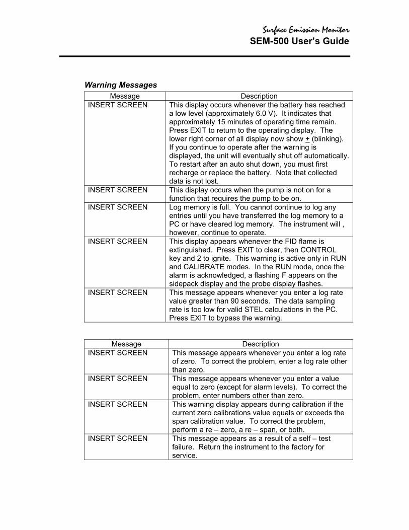
Warning Messages Message Description
INSERT SCREEN This display occurs whenever the battery has reached a low level (approximately 6.0 V). It indicates that approximately 15 minutes of operating time remain. Press EXIT to return to the operating display. The lower right corner of all display now show + (blinking). If you continue to operate after the warning is displayed, the unit will eventually shut off automatically. To restart after an auto shut down, you must first recharge or replace the battery. Note that collected data is not lost.
INSERT SCREEN This display occurs when the pump is not on for a function that requires the pump to be on.
INSERT SCREEN Log memory is full. You cannot continue to log any entries until you have transferred the log memory to a PC or have cleared log memory. The instrument will , however, continue to operate.
INSERT SCREEN This display appears whenever the FID flame is extinguished. Press EXIT to clear, then CONTROL key and 2 to ignite. This warning is active only in RUN and CALIBRATE modes. In the RUN mode, once the alarm is acknowledged, a flashing F appears on the sidepack display and the probe display flashes.
INSERT SCREEN This message appears whenever you enter a log rate value greater than 90 seconds. The data sampling rate is too low for valid STEL calculations in the PC. Press EXIT to bypass the warning.
Message Description INSERT SCREEN This message appears whenever you enter a log rate
of zero. To correct the problem, enter a log rate other than zero.
INSERT SCREEN This message appears whenever you enter a value equal to zero (except for alarm levels). To correct the problem, enter numbers other than zero.
INSERT SCREEN This warning display appears during calibration if the current zero calibrations value equals or exceeds the span calibration value. To correct the problem, perform a re – zero, a re – span, or both.
INSERT SCREEN This message appears as a result of a self – test failure. Return the instrument to the factory for service.
SSuurrffaaccee EEmmiissssiioonn MMoonniittoorr SEM-500 User’s Guide
ACCESSORIES
Telescoping Extension Option
To use an optional telescoping extension, loosen the probe nut and unplug the sampling assembly. Next, insert the telescoping wand and tighten the probe nut. Then, insert the appropriate sampling assembly into the other end of the extension unit and tighten the retaining nut. INSERT PICTURE Figure 13. Telescoping Extension Option
Activated Charcoal Filter Adapter The Activated Charcoal Filter Adapter is an accessory that can be installed or attached to the end of the standard probe or the end of a telescoping extension. The filter is typically filled with activated charcoal, which acts as an adsorbent and effectively filters out organic vapors other then methane or ethane. A screw cap on the probe end may be removed for refilling the filter with activated charcoal or other filtering medium. Applications of the filter include: 1. Obtaining a clean air sample for zero baseline check and adjustment. 2. Rapid screening of methane and non – methane organic vapors. 3. Selective screening for natural gas surveys. The charcoal filter adapter fits directly into the telescoping wand. The life of the filter depends on the time in use, the types of compounds, and concentrations of the compound being filtered. Under typical industrial air monitoring conditions, the filter will last for many days of continuous sampling.

SSuurrffaaccee EEmmiissssiioonn MMoonniittoorr SEM-500 User’s Guide