sem-4th branch-civil engineering
TRANSCRIPT
GOVERNMENT POLYTECHNIC NABARANGAPUR
SEM-4TH
BRANCH-CIVIL ENGINEERING
LECTURE NOTE ON
DESIGN OF CONCRETE STRUCTURES (Th.1)
Prepared by
SUBRAT KUMAR PANIGRAHI
( Lecturer in Civil Engineering)
Introduction
Reinforced concrete, as a composite material, has occupied a special place in
the modern construction of different types of structures due to its several
advantages. Due to its flexibility in form and superiority in performance, it has
replaced, to a large extent, the earlier materials like stone, timber and steel.
Further, architect's scope and imaginations have widened to a great extent due
to its mouldability and monolithicity. Thus, it has helped the architects and
engineers to build several attractive shell forms and other curved structures.
However, its role in several straight line structural forms like multistoried
frames, bridges, foundations etc. is enormous.
Concrete
Concrete is a product obtained artificially by hardening of the mixture of
cement, sand, gravel and water in predetermined proportions.
Depending on the quality and proportions of the ingredients used in the mix the
properties of concrete vary almost as widely as different kinds of stones.
Concrete has enough strength in compression, but has little strength in tension.
Due to this, concrete is weak in bending, shear and torsion. Hence the use of
plain concrete is limited applications where great compressive strength and
weight are the principal requirements and where tensile stresses are either
totally absent or are extremely low.
Properties of Concrete
The important properties of concrete, which govern the design of concrete mix
are as follows
(i) Weight
The unit weights of plain concrete and reinforced concrete made with sand,
gravel of crushed natural stone aggregate may be taken as 24 KN/m3 and 25
KN/m3 respectively.
(ii) Compressive Strength
With given properties of aggregate the compressive strength of concrete
depends primarily on age, cement content and the water cement ratio are given
Table 2 of IS 456:2000. Characteristic strength are based on the strength at 28
days. The strength at 7 days is about two-thirds of that at 28 days with ordinary
portland cement and generally good indicator of strength likely to be obtained.
(iii) Increase in strength with age
There is normally gain of strength beyond 28 days. The quantum of increase
depends upon the grade and type of cement curing and environmental
conditions etc.
(iv) Tensile strength of concrete
The flexure and split tensile strengths of various concrete are given in IS
516:1959 and IS 5816:1970 respectively when the designer wishes to use an
estimate of the tensile strength from compressive strength, the following
formula can be used
Flexural strength, fcr=0.7√fck N/mm2
(v) Elastic Deformation
The modulus of elasticity is primarily influenced by the elastic properties of the
aggregate and to lesser extent on the conditions of curing and age of the
concrete, the mix proportions and the type of cement. The modulus of elasticity
is normally related to the compressive characteristic strength of concrete
Ec=5000√fck N/mm2
Where Ec= the short-term static modulus of elasticity in N/mm2
fck=characteristic cube strength of concrete in N/mm2
(vi) Shrinkage of concrete
Shrinkage is the time dependent deformation, generally compressive in nature.
The constituents of concrete, size of the member and environmental conditions
are the factors on which the total shrinkage of concrete depends. However, the
total shrinkage of concrete is most influenced by the total amount of water
present in the concrete at the time of mixing for a given humidity and
temperature. The cement content, however, influences the total shrinkage of
concrete to a lesser extent. The approximate value of the total shrinkage strain
for design is taken as 0.0003 in the absence of test data (cl. 6.2.4.1).
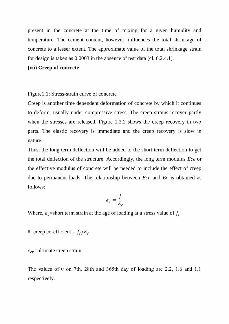
(vii) Creep of concrete
Figure1.1: Stress-strain curve of concrete
Creep is another time dependent deformation of concrete by which it continues
to deform, usually under compressive stress. The creep strains recover partly
when the stresses are released. Figure 1.2.2 shows the creep recovery in two
parts. The elastic recovery is immediate and the creep recovery is slow in
nature.
Thus, the long term deflection will be added to the short term deflection to get
the total deflection of the structure. Accordingly, the long term modulus Ece or
the effective modulus of concrete will be needed to include the effect of creep
due to permanent loads. The relationship between Ece and Ec is obtained as
follows:
Where, =short term strain at the age of loading at a stress value of
θ=creep co-efficient =
=ultimate creep strain
The values of θ on 7th, 28th and 365th day of loading are 2.2, 1.6 and 1.1
respectively.
Then the total strain= =
Where, Ece = effective modulus of concrete.
From the above Equation, we have
The effective modulus of Ece of concrete is used only in the calculation of creep
deflection.
It is seen that the value of creep coefficient θ is reducing with the age of
concrete at loading.
It may also be noted that the ultimate creep strain does not include short
term strain .
The creep of concrete is influenced by
• Properties of concrete
• Water/cement ratio
• Humidity and temperature of curing
• Humidity during the period of use
• Age of concrete at first loading
• Magnitude of stress and its duration
• Surface-volume ratio of the member
(f) Thermal expansion of concrete
The knowledge of thermal expansion of concrete is very important as it is
prepared and remains in service at a wide range of temperature in different
countries having very hot or cold climates. Moreover, concrete will be having
its effect of high temperature during fire. The coefficient of thermal expansion
depends on the nature of cement, aggregate, cement content, relative humidity
and size of the section. IS 456 stipulates (cl. 6.2.6) the values of coefficient of
thermal expansion for concrete / for different types of aggregate.
Workability and Durability of Concrete
Workability and durability of concrete are important properties to be
considered. The relevant issues are discussed in the following:
The workability of a concrete mix gives a measure of the ease with which fresh
concrete can be placed and compacted. The concrete should flow readily into
the form and go around and cover the reinforcement, the mix should retain its
consistency and the aggregates should not segregate. A mix with high
workability is needed where sections are thin and/or reinforcement is
complicated and congested. The main factor affecting workability is the water
content of the mix. Admixtures will increase workability but may reduce
strength. The size of aggregate, its grading and shape, the ratio of coarse to fine
aggregate and the aggregate-to-cement ratio also affect workability to some
degree.
Measurement of workability
(a) Slump test
The fresh concrete is tamped into a standard cone which is lifted off after filling
and the slump is measured. The slump is 25–50 mm for low workability, 50–
100 mm for medium workability and 100–175 mm for high workability. Normal
reinforced concrete requires fresh concrete of medium workability. The slump
test is the usual workability test specified.
(b) Compacting factor test
The degree of compaction achieved by a standard amount of work is measured.
The apparatus consists of two conical hoppers placed over one another and over
a cylinder. The upper hopper is filled with fresh concrete which is then dropped
into the second hopper and into the cylinder which is struck off flush. The
compacting factor is the ratio of the weight of concrete in the cylinder to the
weight of an equal volume of fully compacted concrete. The compacting factor
for concrete of medium workability is about 0.9.
Durability of concrete
A durable concrete performs satisfactorily in the working environment during
its anticipated exposure conditions during service. The durable concrete should
have low permeability with adequate cement content, sufficient low free
water/cement ratio and ensured complete compaction of concrete by adequate
curing. For more information, please refer to cl. 8 of IS 456.
Design mix and nominal mix concrete
In design mix, the proportions of cement, aggregates (sand and gravel), water
and mineral admixtures, if any, are actually designed, while in nominal mix, the
proportions are nominally adopted. The design mix concrete is preferred to the
nominal mix as the former results in the grade of concrete having the specified
workability and characteristic strength (vide cl. 9 of IS 456).
Batching
Mass and volume are the two types of batching for measuring cement, sand,
coarse aggregates, admixtures and water. Coarse aggregates may be gravel,
grade stone chips or other man made aggregates. The quantities of cement,
sand, coarse aggregates and solid admixtures shall be measured by mass. Liquid
admixtures and water are measured either by volume or by mass (cl. 10 of IS
456).
Properties of reinforcing steel
Steel reinforcement used in reinforced concrete may be of the following types
(a) 1. Mild steel bars conforming to IS 432 (part-I)
2. Hot rolled mild steel conforming to IS 1139
(b) 1. Medium tensile steel conforming to IS 432 (part-I)
2. Hot rolled medium tensile steel.
(c) 1. Hot rolled High Yield Strength Deformed (HYSD) steel conforming to IS
1139.
2. Cold-worked steel HYSD bars steel conforming to IS 1786.
(d) 1. Hard drawn steel wire fabric conforming to IS 1566.
2. Rolled steel made from structural steel conforming to Is 226.
1. the most important characteristic of a reinforcing bar is its stress strain curve
and the important property yield stress or 0.2% proof stress, as the case may be.
2. The modules of elasticity E for these steel is 2x10⁵ N/mn2.
3. Mild steel bars have yield strength of 250 N/mm2 and hence it is known as
Fe 250.
4. HYSD bars may be hot rolled high yield strength bars or cold rooked steel
high strength deformed bars. The latter are also known as cold twisted deformed
bars or Tor steel and are available in different grades
i) Fe 415 ii) 500 iii) Fe 550 having 0.2% proof stress as 415N/mm2, 500N/mm2
and 550 N/mm2
5. The reinforcing bars should have sufficient % of elongation.
6. Its coefficients of thermal expansion should be more or less equal to the
cement concrete.
Stress-strain curves for reinforcement
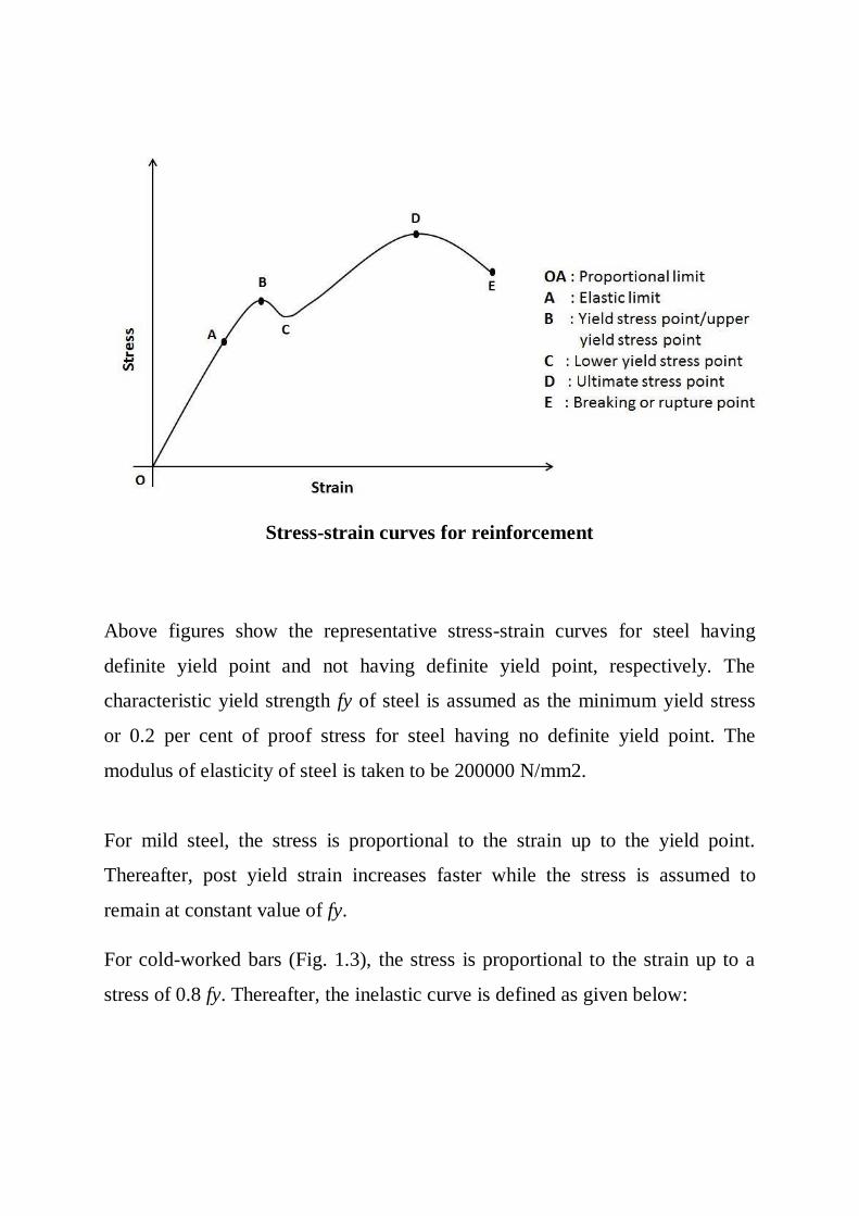
Stress-strain curves for reinforcement
Above figures show the representative stress-strain curves for steel having
definite yield point and not having definite yield point, respectively. The
characteristic yield strength fy of steel is assumed as the minimum yield stress
or 0.2 per cent of proof stress for steel having no definite yield point. The
modulus of elasticity of steel is taken to be 200000 N/mm2.
For mild steel, the stress is proportional to the strain up to the yield point.
Thereafter, post yield strain increases faster while the stress is assumed to
remain at constant value of fy.
For cold-worked bars (Fig. 1.3), the stress is proportional to the strain up to a
stress of 0.8 fy. Thereafter, the inelastic curve is defined as given below:
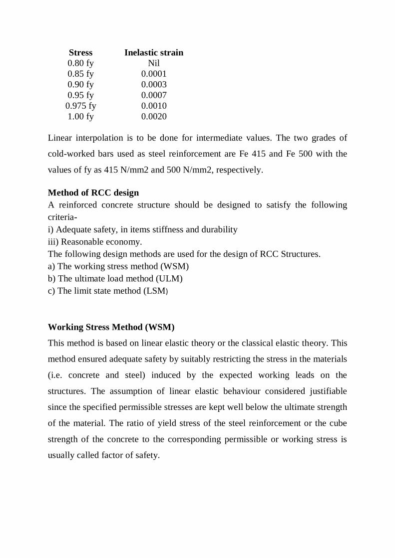
Stress Inelastic strain
0.80 fy Nil
0.85 fy 0.0001
0.90 fy 0.0003
0.95 fy 0.0007
0.975 fy 0.0010
1.00 fy 0.0020
Linear interpolation is to be done for intermediate values. The two grades of
cold-worked bars used as steel reinforcement are Fe 415 and Fe 500 with the
values of fy as 415 N/mm2 and 500 N/mm2, respectively.
Method of RCC design
A reinforced concrete structure should be designed to satisfy the following
criteria-
i) Adequate safety, in items stiffness and durability
iii) Reasonable economy.
The following design methods are used for the design of RCC Structures.
a) The working stress method (WSM)
b) The ultimate load method (ULM)
c) The limit state method (LSM)
Working Stress Method (WSM)
This method is based on linear elastic theory or the classical elastic theory. This
method ensured adequate safety by suitably restricting the stress in the materials
(i.e. concrete and steel) induced by the expected working leads on the
structures. The assumption of linear elastic behaviour considered justifiable
since the specified permissible stresses are kept well below the ultimate strength
of the material. The ratio of yield stress of the steel reinforcement or the cube
strength of the concrete to the corresponding permissible or working stress is
usually called factor of safety.
The WSM uses a factor of safety of about 3 with respect to the cube strength of
concrete and a factor of safety of about 1.8 with respect to the yield strength of
steel.
Ultimate load method (ULM)
The method is based on the ultimate strength of reinforced concrete at ultimate
load is obtained by enhancing the service load by some factor called as load
factor for giving a desired margin of safety .Hence the method is also referred to
as the load factor method or the ultimate strength method.
In the ULM, stress condition at the state of in pending collapse of the structure
is analysed, thus using, the non-linear stress – strain curves of concrete and
steel. The safely measure in the design is obtained by the use of proper load
factor. The satisfactory strength performance at ultimate loads does not
guarantee satisfactory strength performance at ultimate loads does not guarantee
satisfactory serviceability performance at normal service loads.
Limit state method (LSM)
Limit states are the acceptable limits for the safety and serviceability
requirements of the structure before failure occurs. The design of structures by
this method will thus ensure that they will not reach limit states and will not
become unfit for the use for which they are intended. It is worth mentioning that
structures will not just fail or collapse by violating (exceeding) the limit states.
Failure, therefore, implies that clearly defined limit states of structural
usefulness has been exceeded.
Limit state are two types
i) Limit state of collapse
ii) Limit state of serviceability.
Limit states of collapse
The limit state of collapse of the structure or part of the structure could be
assessed from rupture of one or more critical sections and from bucking due to
elastic bending, shear, torsion and axial loads at every section shall not be less
than the appropriate value at that section produced by the probable most
unfavourable combination of loads on the structure using the appropriate factor
of safely.
Limit state of serviceability
Limit state of serviceability deals with deflection and crocking of structures
under service loads, durability under working environment during their
anticipated exposure conditions during service, stability of structures as a
whole, fire resistance etc.
Characteristic and design values and partial safety factor
1. Characteristic strength of materials.
The term ‗characteristic strength‘ means that value of the strength of material
below which not more than minimum acceptable percentage of test results are
expected to fall. IS 456:2000 have accepted the minimum acceptable percentage
as 5% for reinforced concrete structures. This means that there is 5% for
probability or chance of the actual strength being less than the characteristic
strength.
The design strength should be lower than the mean strength (fm)
Characteristic strength = Mean strength –K x standard deviation or
fk=fm-K
Where, fk=characteristic strength of the material
fm=mean strength
K=constant =1.65
=standard deviation for a set of test results.
Characteristic strength of concrete
Characteristic strength of concrete is denoted by fck (N/mm2) and its value is
different for different grades of concrete e.g. M 15, M25 etc. In the symbol ‗M‘
used for designation of concrete mix, refers to the mix and the number refers to
the specified characteristic compressive strength of 150 mm size cube at 28
days expressed in N/mm2
Characteristic strength of steel
Until the relevant Indian Standard specification for reinforcing steel are
modified to include the concept of characteristic strength, the characteristic
value shall be assumed as the minimum yield stress or 0.2% proof stress
specified in the relevant Indian Standard specification. The characteristic
strength of steel designated by symbol fy (N/mm2)
Characteristic loads
The term ‗Characteristic load‘ means that values of load which has a 95%
probability of not being exceeded during that life of the structure.
The design load should be more than average load obtained from statistic, we
have
Fk=Fm+K
Where, Fk=characteristic load;
Fm= mean load
K=constant=2.65;
=standard deviation for the load.
Design strength of materials
The design strength of materials (fd) is given by
Where, fk=characteristic strength of material.
= partial safety factor appropriate to the material and the limit state being
Design loads
The design load ( Fd) is given by.
Fd=Fk.
=partial safety factor appropriate to the nature of loading and the limit state
being considered.
The design load obtained by multi plying the characteristic load by the partial
safety factor for load is also known as factored load.
Partial safety factor ( ) for materials
When assessing the strength of a structure or structural member for the limit
state of collapse, the values of partial safety factor, should be taken as 1.15
for steel.
Thus, in the limit state method , the design stress for steel reinforcement is
given by /1.15=0.87
According to IS 456:2000 for design purpose the compressive strength of
concrete in the structure shall be assumed to be 0.67 times the characteristic
strength of concrete in cube and partial safety factor =1.5 shall be applied in
addition to this. Thus, the design stress in concrete is given by
Limit state of collapse in flexure
Assumptions
a) Plane sections normal to the beam axis remain plane after bending, i.e., in an
initially straight beam, strain varies linearly over the depth of the section.
b) The maximum compressive strain in concrete (at the outermost fibre)
shall be taken as 0.0035 in bending.
c) The relationship between the compressive stress distribution in concrete and
the strain in concrete may be assumed to be rectangle, trapezoid, parabola or
any other shape which results in prediction of strength in substantial agreement
with the results of test. An acceptable stress-strain curve is given below in
figure 1.6. For design purposes, the compressive strength of concrete in the
structure shall be assumed to be 0.67 times the characteristic strength. The
partial safety factor y, = 1.5 shall be applied in addition to this.
d) The tensile strength of the concrete is ignored.
e) The stresses in the reinforcement are derived from representative stress-strain
curve for the type of steel used. Typical curves are given in figure 1.3. For
design purposes the partial safety factor equal to 1.15 shall be applied.
f) The maximum strain in the tension reinforcement in the section at failure
shall not be less
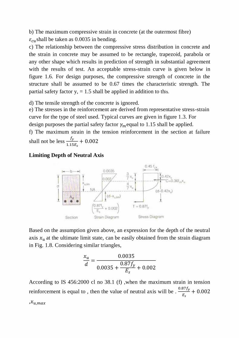
Limiting Depth of Neutral Axis
Based on the assumption given above, an expression for the depth of the neutral
axis at the ultimate limit state, can be easily obtained from the strain diagram
in Fig. 1.8. Considering similar triangles,
According to IS 456:2000 cl no 38.1 (f) ,when the maximum strain in tension
reinforcement is equal to , then the value of neutral axis will be .
,
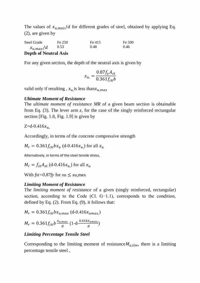
The values of for different grades of steel, obtained by applying Eq.
(2), are given by
Steel Grade Fe 250 Fe 415 Fe 500
0.53 0.48 0.46
Depth of Neutral Axis
For any given section, the depth of the neutral axis is given by
valid only if resulting , is less than
Ultimate Moment of Resistance
The ultimate moment of resistance MR of a given beam section is obtainable
from Eq. (3). The lever arm z, for the case of the singly reinforced rectangular
section [Fig. 1.8, Fig. 1.9] is given by
Z=d-0.416
Accordingly, in terms of the concrete compressive strength
(d-0.416 ) for all
Alternatively, in terms of the steel tensile stress,
(d-0.416 ) for all
With fst=0.87fy for xu xu,max
Limiting Moment of Resistance
The limiting moment of resistance of a given (singly reinforced, rectangular)
section, according to the Code (Cl. G−1.1), corresponds to the condition,
defined by Eq. (2). From Eq. (9), it follows that:
(d-0.416 )
(1-d-
)
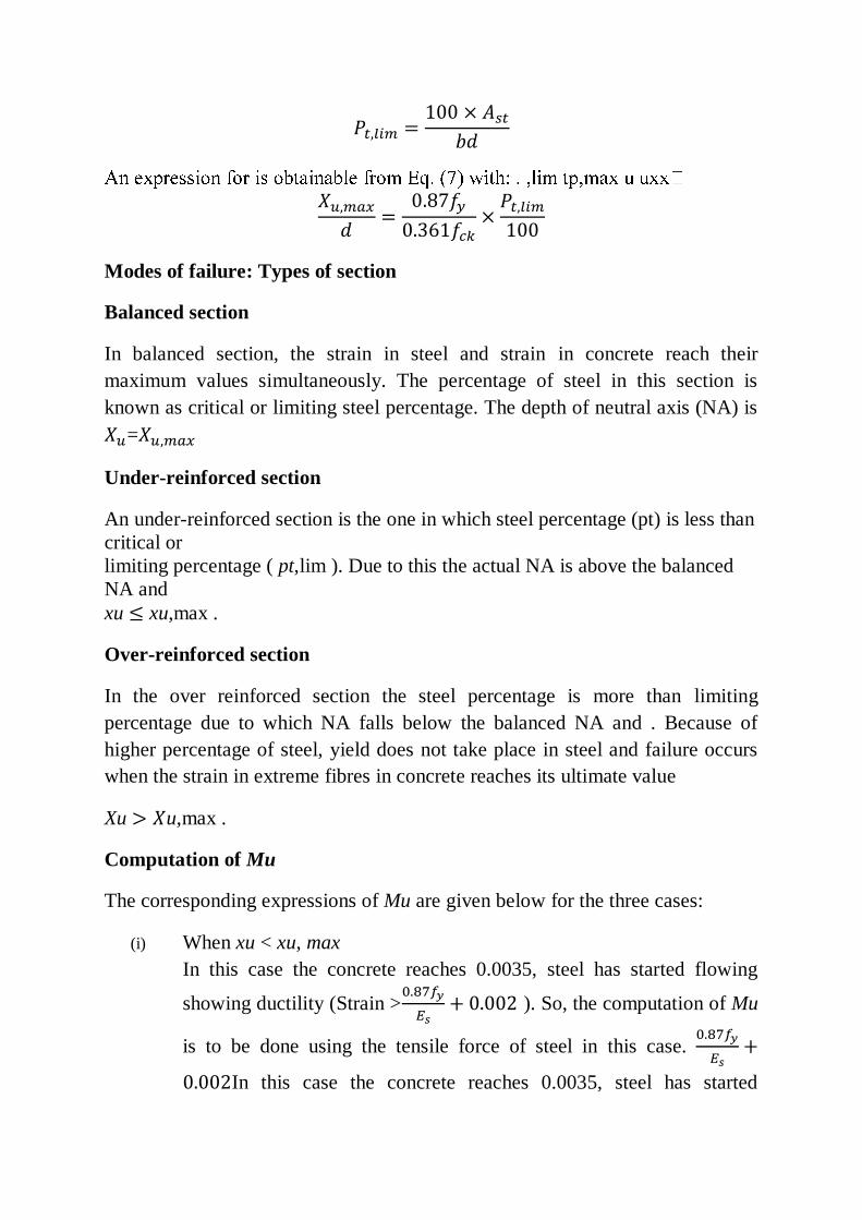
Limiting Percentage Tensile Steel
Corresponding to the limiting moment of resistance , there is a limiting
percentage tensile steel ,
Modes of failure: Types of section
Balanced section
In balanced section, the strain in steel and strain in concrete reach their
maximum values simultaneously. The percentage of steel in this section is
known as critical or limiting steel percentage. The depth of neutral axis (NA) is
=
Under-reinforced section
An under-reinforced section is the one in which steel percentage (pt) is less than
critical or
limiting percentage ( pt,lim ). Due to this the actual NA is above the balanced
NA and
xu xu,max .
Over-reinforced section
In the over reinforced section the steel percentage is more than limiting
percentage due to which NA falls below the balanced NA and . Because of
higher percentage of steel, yield does not take place in steel and failure occurs
when the strain in extreme fibres in concrete reaches its ultimate value
Xu u,max .
Computation of Mu
The corresponding expressions of Mu are given below for the three cases:
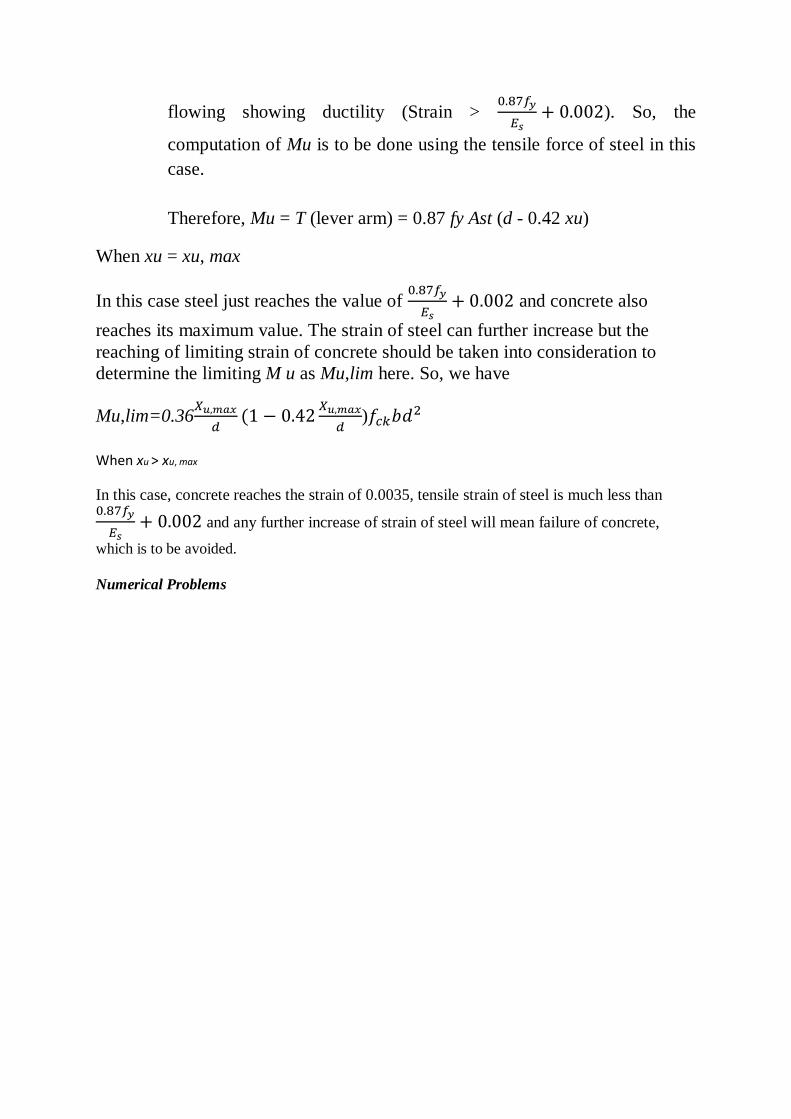
(i) When xu < xu, max
In this case the concrete reaches 0.0035, steel has started flowing
showing ductility (Strain >
). So, the computation of Mu
is to be done using the tensile force of steel in this case.
In this case the concrete reaches 0.0035, steel has started
flowing showing ductility (Strain >
). So, the
computation of Mu is to be done using the tensile force of steel in this
case.
Therefore, Mu = T (lever arm) = 0.87 fy Ast (d - 0.42 xu)
When xu = xu, max
In this case steel just reaches the value of
and concrete also
reaches its maximum value. The strain of steel can further increase but the
reaching of limiting strain of concrete should be taken into consideration to
determine the limiting M u as Mu,lim here. So, we have
Mu,lim=0.36
)
When xu > xu, max
In this case, concrete reaches the strain of 0.0035, tensile strain of steel is much less than
and any further increase of strain of steel will mean failure of concrete,
which is to be avoided.
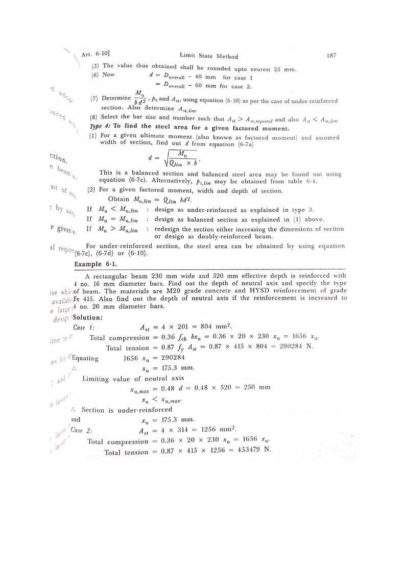
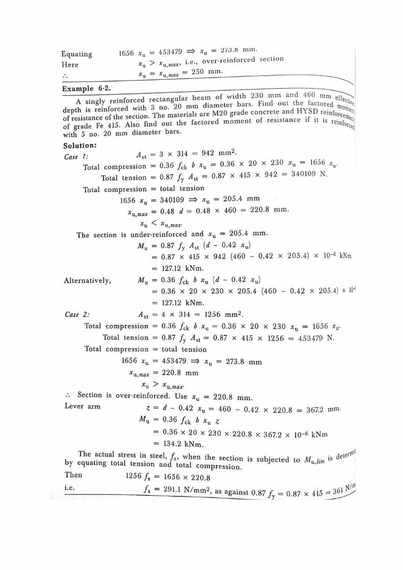
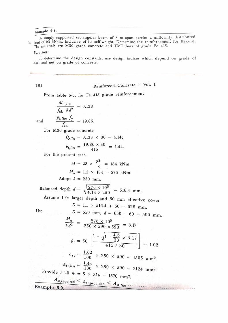
Numerical Problems
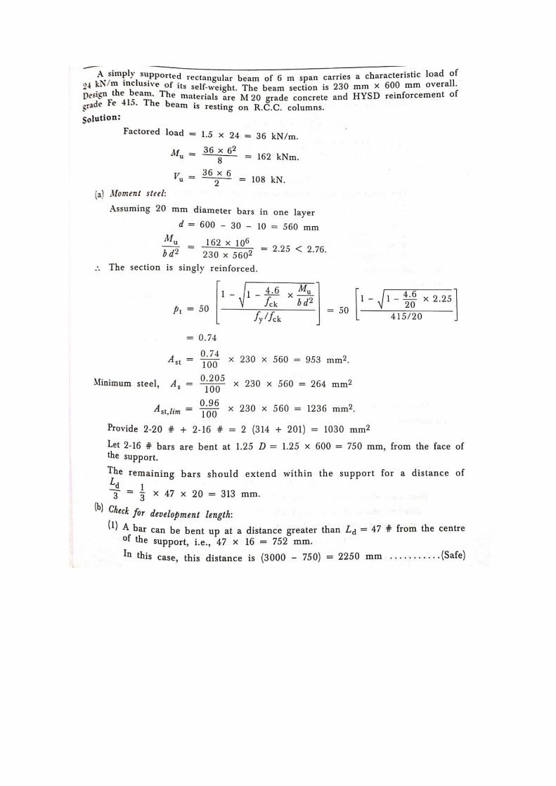

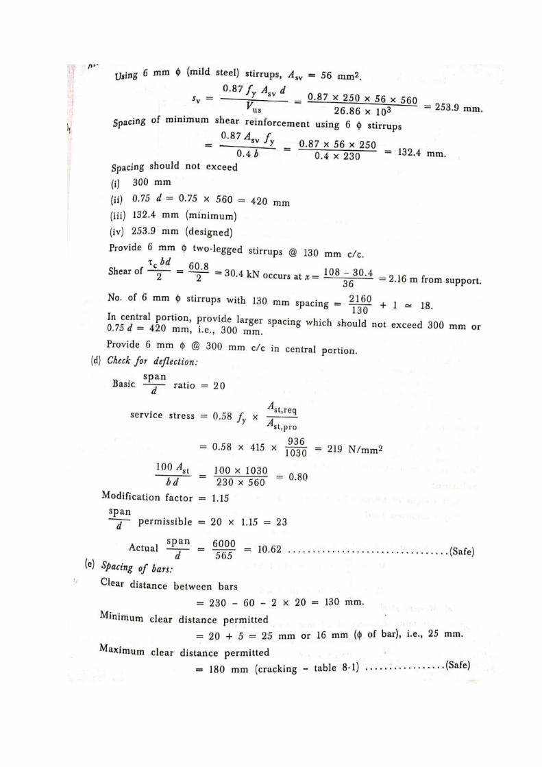
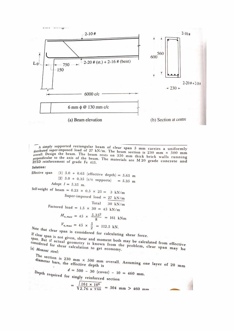
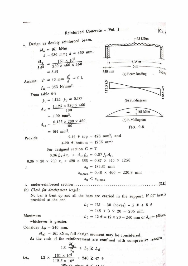
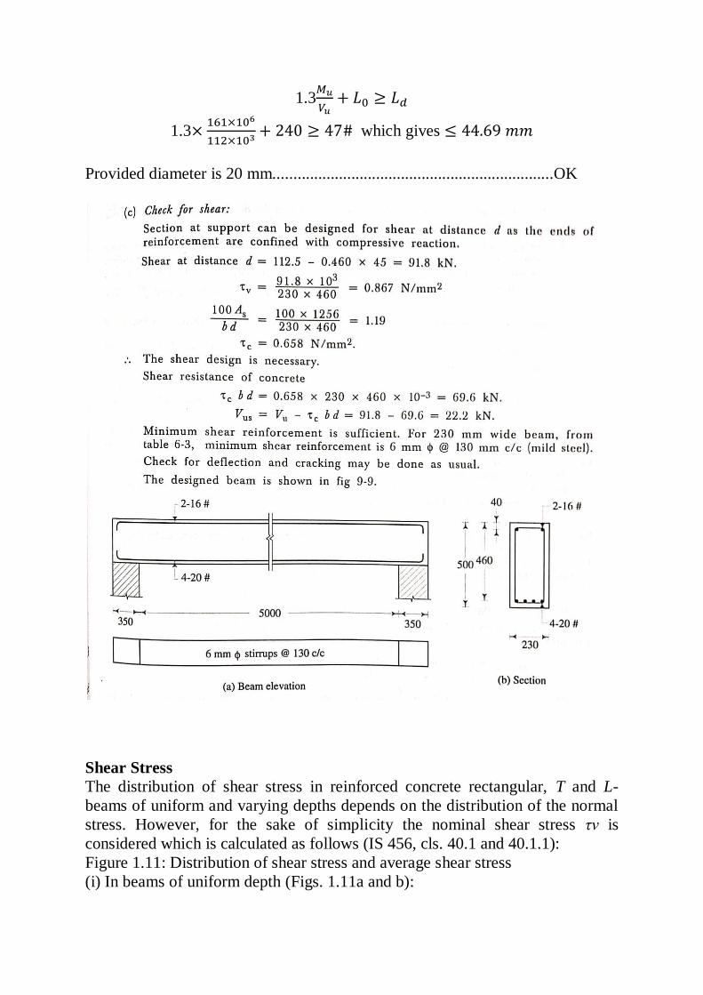
1.3
1.3
which gives
Provided diameter is 20 mm....................................................................OK
Shear Stress
The distribution of shear stress in reinforced concrete rectangular, T and L-
beams of uniform and varying depths depends on the distribution of the normal
stress. However, for the sake of simplicity the nominal shear stress τv is
considered which is calculated as follows (IS 456, cls. 40.1 and 40.1.1):
Figure 1.11: Distribution of shear stress and average shear stress
(i) In beams of uniform depth (Figs. 1.11a and b):
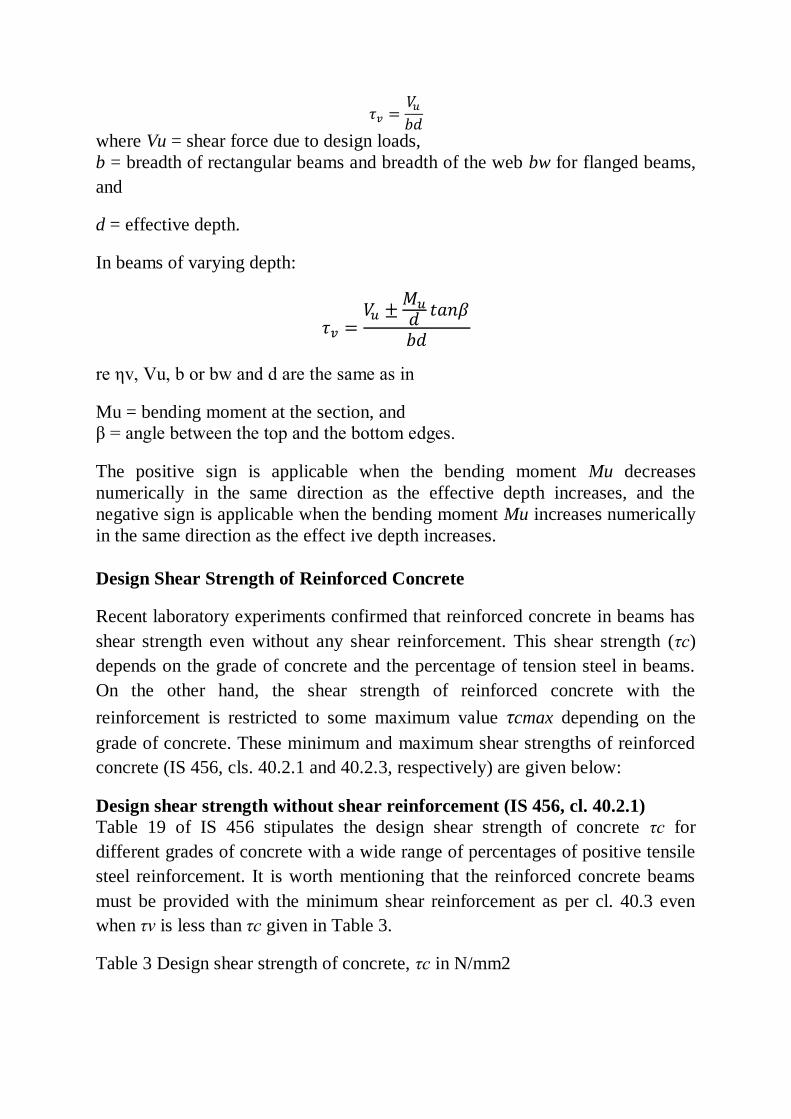
where Vu = shear force due to design loads,
b = breadth of rectangular beams and breadth of the web bw for flanged beams,
and
d = effective depth.
In beams of varying depth:
re ηv, Vu, b or bw and d are the same as in
Mu = bending moment at the section, and
β = angle between the top and the bottom edges.
The positive sign is applicable when the bending moment Mu decreases
numerically in the same direction as the effective depth increases, and the
negative sign is applicable when the bending moment Mu increases numerically
in the same direction as the effect ive depth increases.
Design Shear Strength of Reinforced Concrete
Recent laboratory experiments confirmed that reinforced concrete in beams has
shear strength even without any shear reinforcement. This shear strength (τc)
depends on the grade of concrete and the percentage of tension steel in beams.
On the other hand, the shear strength of reinforced concrete with the
reinforcement is restricted to some maximum value τcmax depending on the
grade of concrete. These minimum and maximum shear strengths of reinforced
concrete (IS 456, cls. 40.2.1 and 40.2.3, respectively) are given below:
Design shear strength without shear reinforcement (IS 456, cl. 40.2.1)
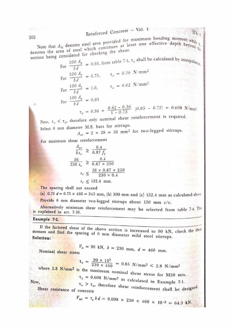
Table 19 of IS 456 stipulates the design shear strength of concrete τc for
different grades of concrete with a wide range of percentages of positive tensile
steel reinforcement. It is worth mentioning that the reinforced concrete beams
must be provided with the minimum shear reinforcement as per cl. 40.3 even
when τv is less than τc given in Table 3.
Table 3 Design shear strength of concrete, τc in N/mm2
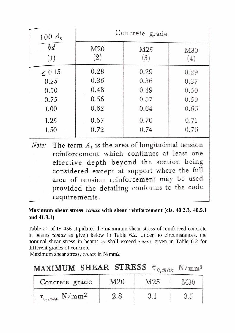
Maximum shear stress τcmax with shear reinforcement (cls. 40.2.3, 40.5.1
and 41.3.1)
Table 20 of IS 456 stipulates the maximum shear stress of reinforced concrete
in beams τcmax as given below in Table 6.2. Under no circumstances, the
nominal shear stress in beams τv shall exceed τcmax given in Table 6.2 for
different grades of concrete.
Maximum shear stress, τcmax in N/mm2

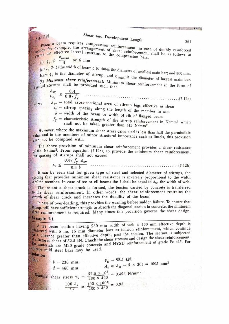
Minimum Shear Reinforcement (cls. 40.3, 26.5.1.5 and 26.5.1.6 of IS 456)
For deformed bars conforming to IS 1786, these values shall be increased by 60
per cent. For bars in compression, the values of bond stress in tension shall be
increased by 25 per cent.
Minimum shear reinforcement has to be provided even when τv is less than τc
given in Table 3 as recommended in cl. 40.3 of IS 456. The amount of
minimum shear reinforcement, as given in cl. 26.5.1.6, is given below.
The minimum shear reinforcement in the form of stirrups shall be provided such
that:
where Asv = total cross-sectional area of stirrup legs effective in shear,
sv = stirrup spacing along the length of the member,
b = breadth of the beam or breadth of the web of the web of flanged beam bw,
and
fy = characteristic strength of the stirrup reinforcement in N/mm2 which shall
not be taken greater than 415 N/mm2.
The above provision is not applicable for members of minor structural
importance such as lintels where the maximum shear stress calculated is less
than half the permissible value.
The minimum shear reinforcement is provided for the following:
(i) Any sudden failure of beams is prevented if concrete cover bursts and the
bond to the tension steel is lost.
(ii) Brittle shear failure is arrested which would have occurred without shear
reinforcement.
(iii) Tension failure is prevented which would have occurred due to shrinkage,
thermal stresses and internal cracking in beams.
(iv) To hold the reinforcement in place when concrete is poured.
(v) Section becomes effective with the tie effect of the compression steel.
Further, cl. 26.5.1.5 of IS 456 stipulates that the maximum spacing of shear
reinforcement measured along the axis of the member shall not be more than
0.75 d for vertical stirrups and d for inclined stirrups at 45o, where d is the
effective depth of the section. However, the spacing shall not exceed 300 mm in
any case.
Development Length
When a reinforcing bar is embedded in concrete, the concrete adheresto its
surface and resist any force that tries to cause slippage of bar relative to its
surrounding concrete, by a phenomenon called Bond.
Bond between steel and concrete should be perfect at service loads. Bond
transfers stress from one material to the other, by strain compatibility.
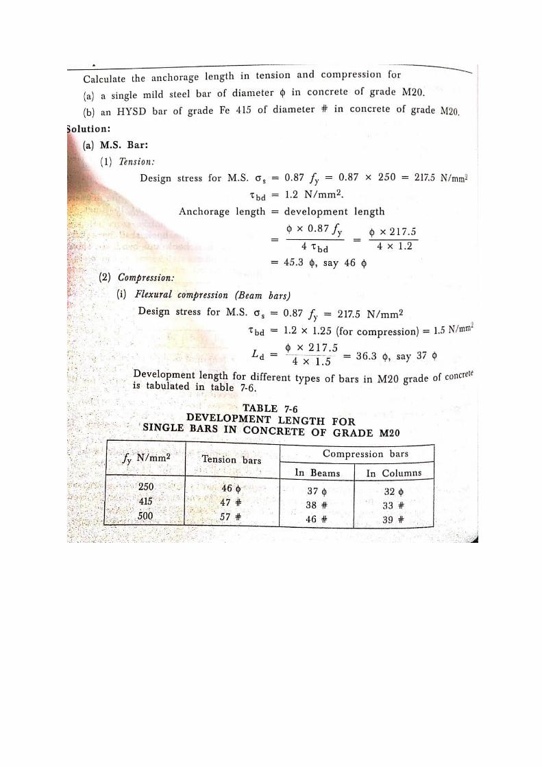
Development length
The reinforcement bar must extend the concrete sufficiently so that it can
develop the required stress. The extended length of the bar force the concrete is
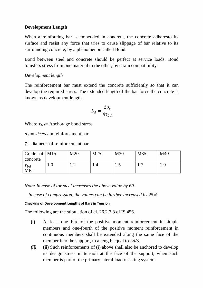
known as development length.
Where = Anchorage bond stress
in reinforcement bar
= diameter of reinforcement bar
Grade of
concrete
M15 M20 M25 M30 M35 M40
MPa
1.0 1.2 1.4 1.5 1.7 1.9
Note: In case of tor steel increases the above value by 60.
In case of compression, the values can be further increased by 25%
Checking of Development Lengths of Bars in Tension
The following are the stipulation of cl. 26.2.3.3 of IS 456.
(i) At least one-third of the positive moment reinforcement in simple
members and one-fourth of the positive moment reinforcement in
continuous members shall be extended along the same face of the
member into the support, to a length equal to Ld/3.
(ii) (ii) Such reinforcements of (i) above shall also be anchored to develop
its design stress in tension at the face of the support, when such
member is part of the primary lateral load resisting system.
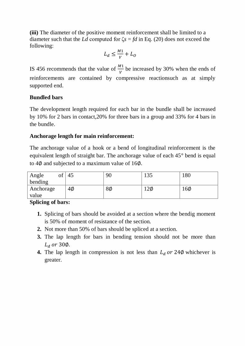
(iii) The diameter of the positive moment reinforcement shall be limited to a
diameter such that the Ld computed for ζs = fd in Eq. (20) does not exceed the
following:
IS 456 recommends that the value of
be increased by 30% when the ends of
reinforcements are contained by compressive reactionsuch as at simply
supported end.
Bundled bars
The development length required for each bar in the bundle shall be increased
by 10% for 2 bars in contact,20% for three bars in a group and 33% for 4 bars in
the bundle.
Anchorage length for main reinforcement:
The anchorage value of a hook or a bend of longitudinal reinforcement is the
equivalent length of straight bar. The anchorage value of each 45 bend is equal
to 4 and subjected to a maximum value of 16
Angle of
bending
45 90 135 180
Anchorage
value
4 8 12 16
Splicing of bars:
1. Splicing of bars should be avoided at a section where the bendig moment
is 50% of moment of resistance of the section.
2. Not more than 50% of bars should be spliced at a section.
3. The lap length for bars in bending tension should not be more than
4. The lap length in compression is not less than whichever is
greater.
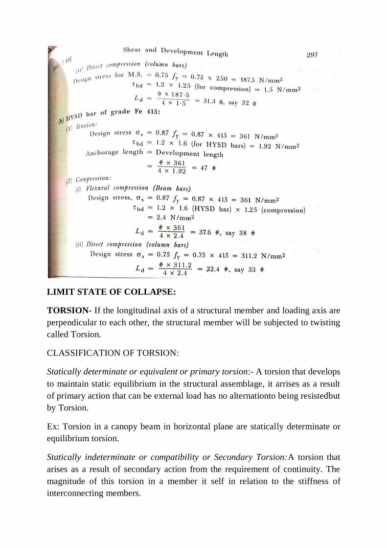
LIMIT STATE OF COLLAPSE:
TORSION- If the longitudinal axis of a structural member and loading axis are
perpendicular to each other, the structural member will be subjected to twisting
called Torsion.
CLASSIFICATION OF TORSION:
Statically determinate or equivalent or primary torsion:- A torsion that develops
to maintain static equilibrium in the structural assemblage, it arrises as a result
of primary action that can be external load has no alternationto being resistedbut
by Torsion.
Ex: Torsion in a canopy beam in horizontal plane are statically determinate or
equilibrium torsion.
Statically indeterminate or compatibility or Secondary Torsion:A torsion that
arises as a result of secondary action from the requirement of continuity. The
magnitude of this torsion in a member it self in relation to the stiffness of
interconnecting members.
Approach of Design for Combined Bending, Shear and Torsion as per IS 456
As per the stipulations of IS 456, the longitudinal and transverse reinforcements
are determined taking into account the combined effects of bending moment,
shear force and torsional moment. Two impirical relations of equivalent shear
and equivalent bending moment are given. These fictitious shear force and
bending moment, designated as equivalent shear and equivalent bending
moment, are separate functions of actual shear and torsion, and actual
bending moment and torsion, respectively. The total vertical reinforcement is
designed to resist the equivalent shear Ve and the longitudinal reinforcement is
designed to resist the equivalent bending moment Me1 and Me2, as explained in
secs. 6.16.6 and 6.16.7, respectively. These design rules are applicable to beams
of solid rectangular cross-section. However, they may be applied to flanged
beams by substituting bw for b. IS 456 further suggests to refer to specialist
literature for the flanged beams as the design adopting the code procedure is
generally conservative.
Critical Section (cl. 41.2 of IS 456)
As per cl. 41.2 of IS 456, sections located less than a distance d from the face of
the support is to be designed for the same torsion as computed at a distance d,
where d is the effective depth of the beam.
Shear and Torsion
The equivalent shear, a function of the actual shear and torsional moment is
determined from the following impirical relation:
Ve = Vu + 1.6(Tu/b)
where Ve = equivalent shear,
Vu = actual shear,
Tu = actual torsional moment,
b = breadth of beam.
The equivalent nominal shear stress is determined from:
However, ve τ shall not exceed c max τ given in Table 20 of IS 456
Minimum shear reinforcement is to be provided as per cl. 26.5.1.6 of IS 456, if
the equivalent nominal shear stress obtained from Eq.6.23 does not exceed
given in Table 19 of IS 456
=
If is greater than Both longitudinal and transverse reinforcement shall be
provided.
Reinforcement in Members subjected to Torsion
Reinforcement for torsion shall consist of longitudinal and transverse
reinforcement as mentioned in sec. 6.16.6(d).
The longitudinal flexural tension reinforcement shall be determined to resist an
equivalent bending moment Me1 as given below:
where Mu = bending moment at the cross-section, and
Mt = (Tu/1.7) {1 + (D/b)}
where Tu = torsional moment,
D = overall depth of the beam, and
b = breadth of the beam.
The Me2 will be considered as acting in the opposite sense to the moment Mu.
The transverse reinforcement consisting of two legged closed loops (Fig.6.16.2) enclosing the corner
longitudinal bars shall be provided having an area of cross-section Asv given below:
or
=
whichever is more
where Tu = torsional moment, Vu = shear force, sv = spacing of the stirrup
reinforcement, b1 = centre to centre distance between corner bars in the
direction of the width, d1 = centre to centre distance between corner bars,
b = breadth of the member, fy = characteristic strength of the stirrup
reinforcement, = equivalent shear stress and = shear strength of concrete a
Requirements of Reinforcement
Tension Reinforcement
The minimum area of tension reinforcement should be governed by
As /(bd) = 0.85/fy
where As = minimum area of tension reinforcement, b = breadth of rectangular
beam or breadth of web of T-beam, d = effective depth of beam, fy =
characteristic strength of reinforcement in N/mm2
The maximum area of tension reinforcement shall not exceed 0.04 bD, where D
is the overall depth of the beam.
Compression reinforcement
The maximum area of compression reinforcement shall not exceed 0.04 bD.
They shall be enclosed by stirrups for effective lateral restraint.
Side face reinforcement
Beams exceeding the depth of 750 mm and subjected to bending moment and
shear shall have side face reinforcement. However, if the beams are having
torsional moment also, the side face reinforcement shall be provided for the
overall depth exceeding 450 mm. The total area of side face reinforcement shall
be at least 0.1 per cent of the web area and shall be distributed equally on two
faces at a spacing not exceeding 300 mm or web thickness, whichever is less.
Maximum spacing of shear reinforcement
The centre to centre spacing of shear reinforcement shall not be more than 0.75
d for vertical stirrups and d for inclined stirrups at 45o , but not exceeding 300
mm, where d is the effective depth of the section
.
Reinforced Concrete Slab Design
Slabs spanning in one direction: supported at two opposite ends
Slabs supporting on all four sides: these are further classified into two types
based on aspect ratio.
One way slab :if
Two way slab :if
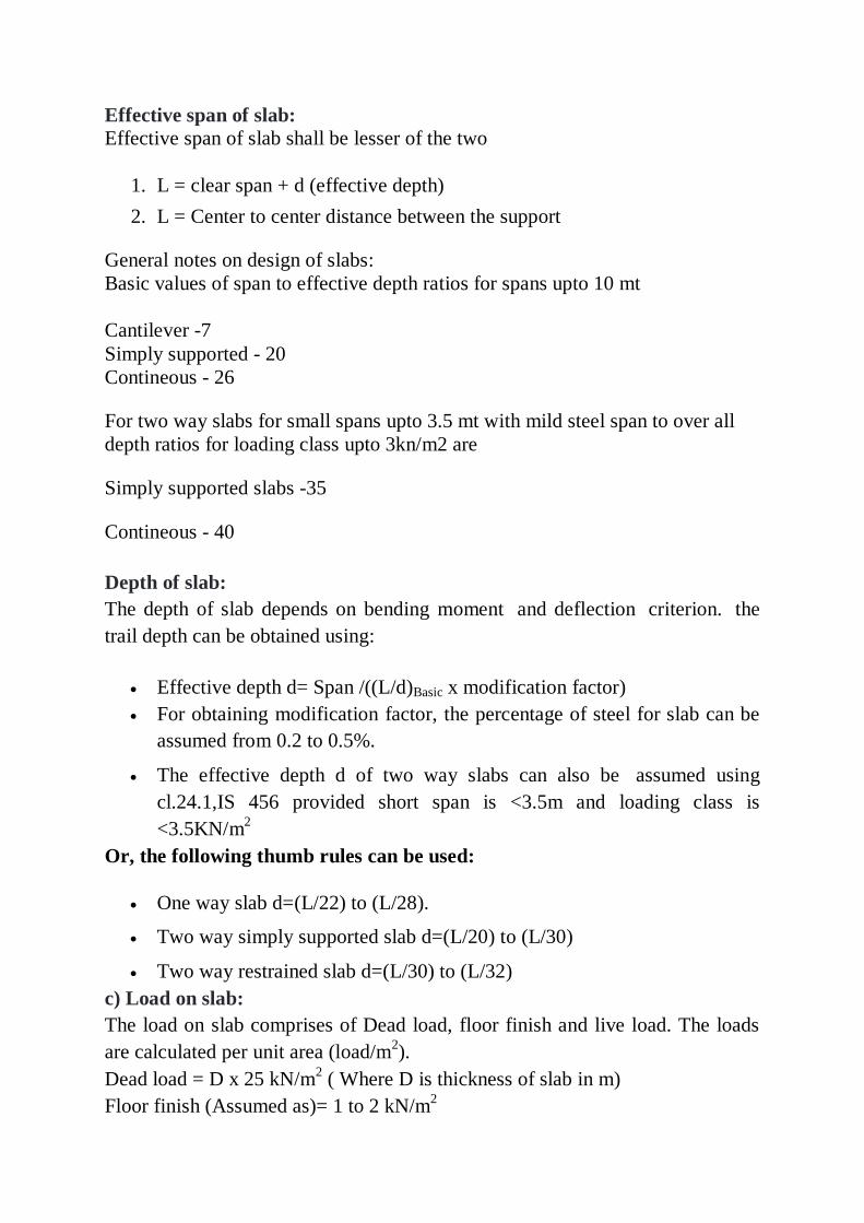
Effective span of slab:
Effective span of slab shall be lesser of the two
1. L = clear span + d (effective depth)
2. L = Center to center distance between the support
General notes on design of slabs:
Basic values of span to effective depth ratios for spans upto 10 mt
Cantilever -7
Simply supported - 20
Contineous - 26
For two way slabs for small spans upto 3.5 mt with mild steel span to over all
depth ratios for loading class upto 3kn/m2 are
Simply supported slabs -35
Contineous - 40
Depth of slab:
The depth of slab depends on bending moment and deflection criterion. the
trail depth can be obtained using:
Effective depth d= Span /((L/d)Basic x modification factor)
For obtaining modification factor, the percentage of steel for slab can be
assumed from 0.2 to 0.5%.
The effective depth d of two way slabs can also be assumed using
cl.24.1,IS 456 provided short span is <3.5m and loading class is
<3.5KN/m2
Or, the following thumb rules can be used:
One way slab d=(L/22) to (L/28).
Two way simply supported slab d=(L/20) to (L/30)
Two way restrained slab d=(L/30) to (L/32)
c) Load on slab:
The load on slab comprises of Dead load, floor finish and live load. The loads
are calculated per unit area (load/m2).
Dead load = D x 25 kN/m2 ( Where D is thickness of slab in m)
Floor finish (Assumed as)= 1 to 2 kN/m2
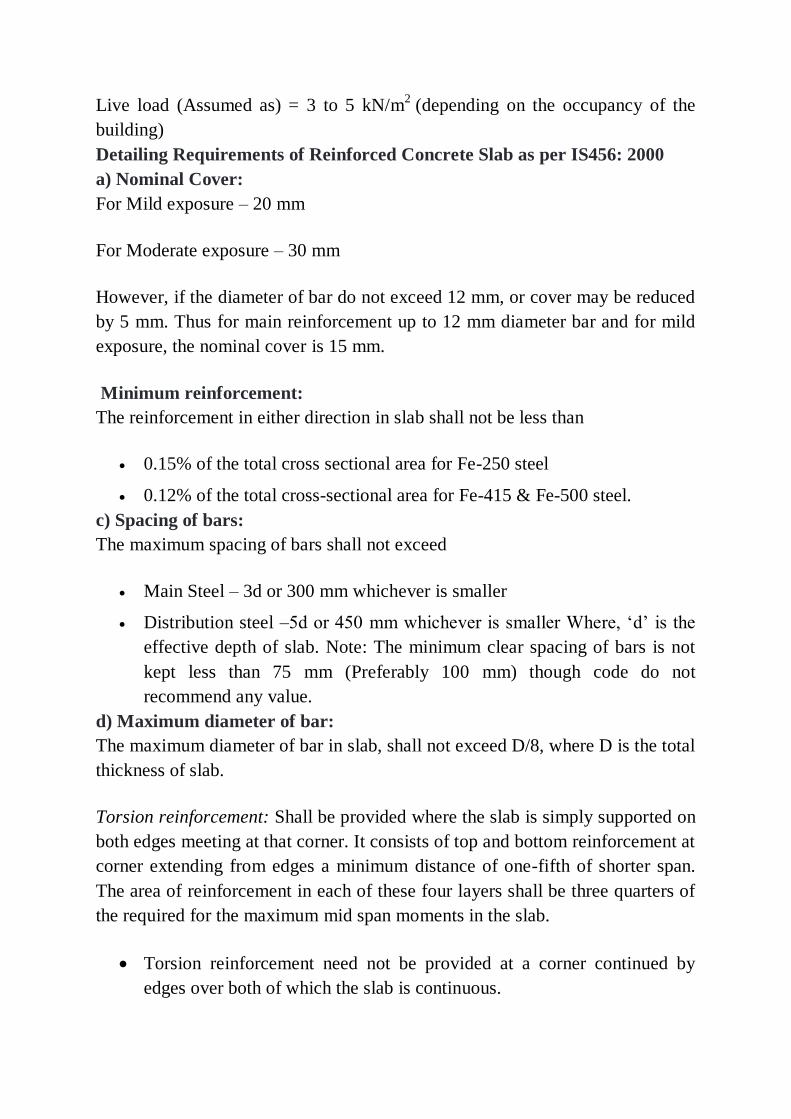
Live load (Assumed as) = 3 to 5 kN/m2 (depending on the occupancy of the
building)
Detailing Requirements of Reinforced Concrete Slab as per IS456: 2000
a) Nominal Cover:
For Mild exposure – 20 mm
For Moderate exposure – 30 mm
However, if the diameter of bar do not exceed 12 mm, or cover may be reduced
by 5 mm. Thus for main reinforcement up to 12 mm diameter bar and for mild
exposure, the nominal cover is 15 mm.
Minimum reinforcement:
The reinforcement in either direction in slab shall not be less than
0.15% of the total cross sectional area for Fe-250 steel
0.12% of the total cross-sectional area for Fe-415 & Fe-500 steel.
c) Spacing of bars:
The maximum spacing of bars shall not exceed
Main Steel – 3d or 300 mm whichever is smaller
Distribution steel –5d or 450 mm whichever is smaller Where, ‘d’ is the
effective depth of slab. Note: The minimum clear spacing of bars is not
kept less than 75 mm (Preferably 100 mm) though code do not
recommend any value.
d) Maximum diameter of bar:
The maximum diameter of bar in slab, shall not exceed D/8, where D is the total
thickness of slab.
Torsion reinforcement: Shall be provided where the slab is simply supported on
both edges meeting at that corner. It consists of top and bottom reinforcement at
corner extending from edges a minimum distance of one-fifth of shorter span.
The area of reinforcement in each of these four layers shall be three quarters of
the required for the maximum mid span moments in the slab.
Torsion reinforcement need not be provided at a corner continued by
edges over both of which the slab is continuous.
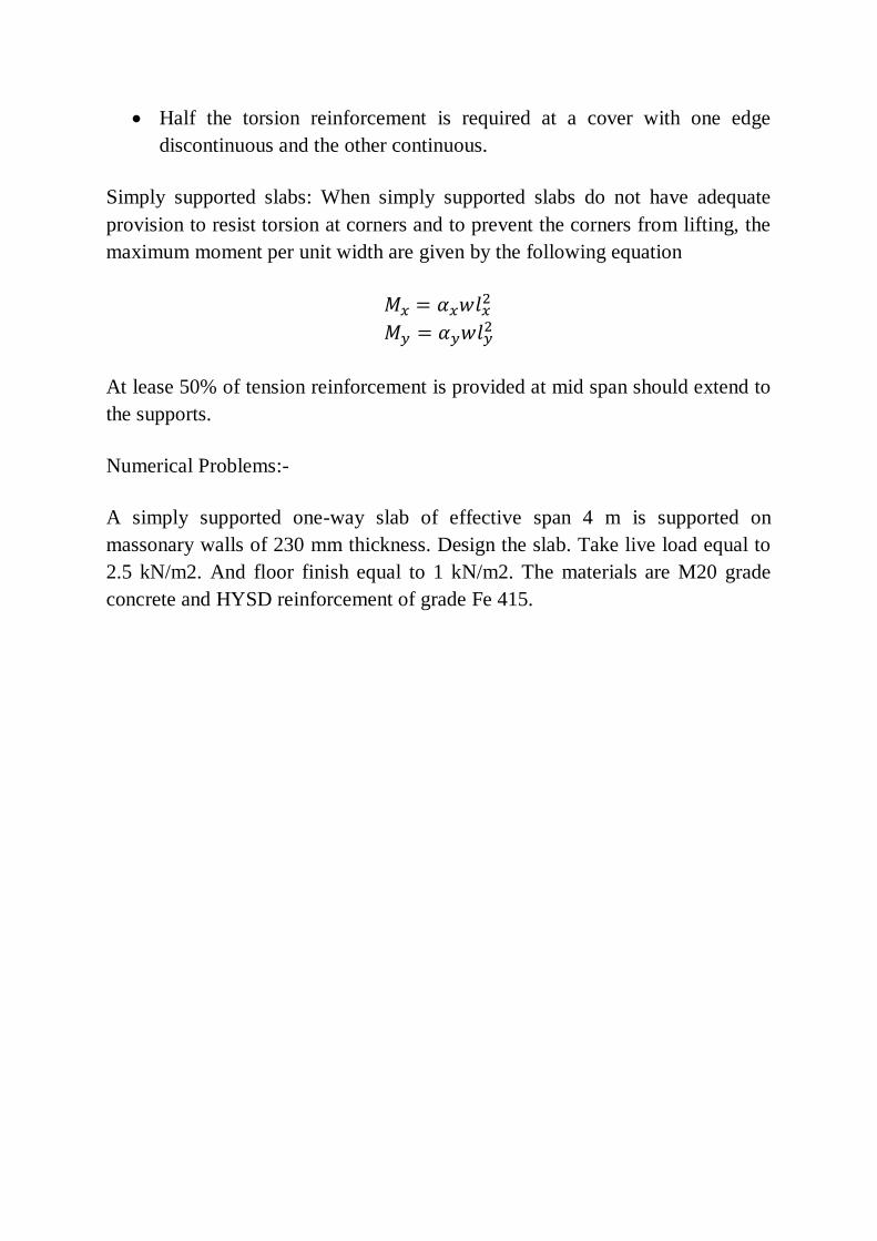
Half the torsion reinforcement is required at a cover with one edge
discontinuous and the other continuous.
Simply supported slabs: When simply supported slabs do not have adequate
provision to resist torsion at corners and to prevent the corners from lifting, the
maximum moment per unit width are given by the following equation
At lease 50% of tension reinforcement is provided at mid span should extend to
the supports.
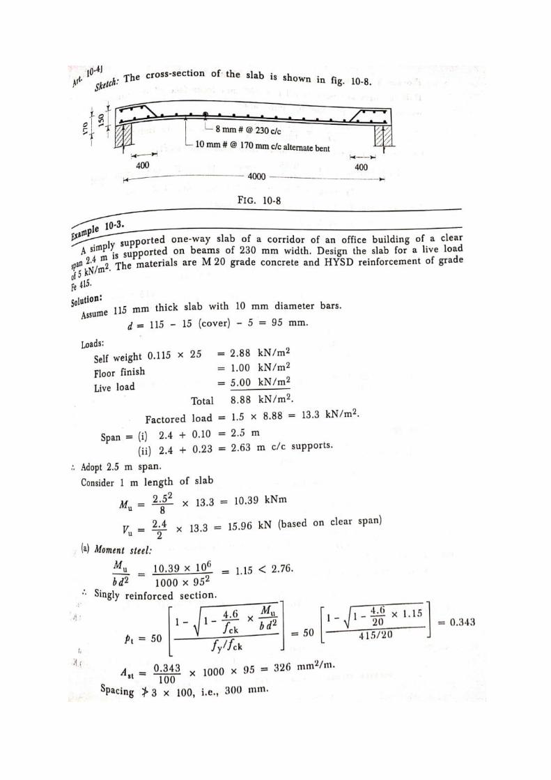
Numerical Problems:-
A simply supported one-way slab of effective span 4 m is supported on
massonary walls of 230 mm thickness. Design the slab. Take live load equal to
2.5 kN/m2. And floor finish equal to 1 kN/m2. The materials are M20 grade
concrete and HYSD reinforcement of grade Fe 415.
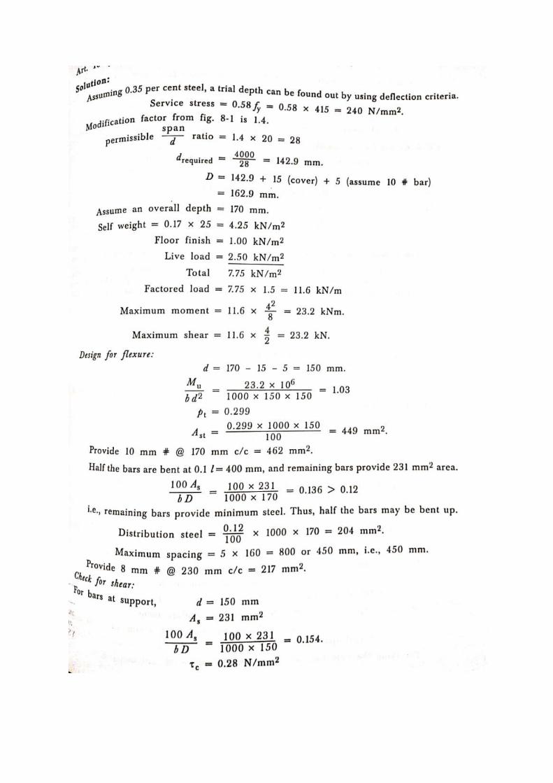
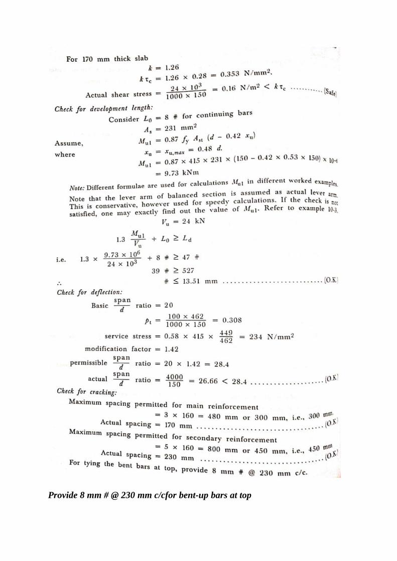
Provide 8 mm # @ 230 mm c/cfor bent-up bars at top
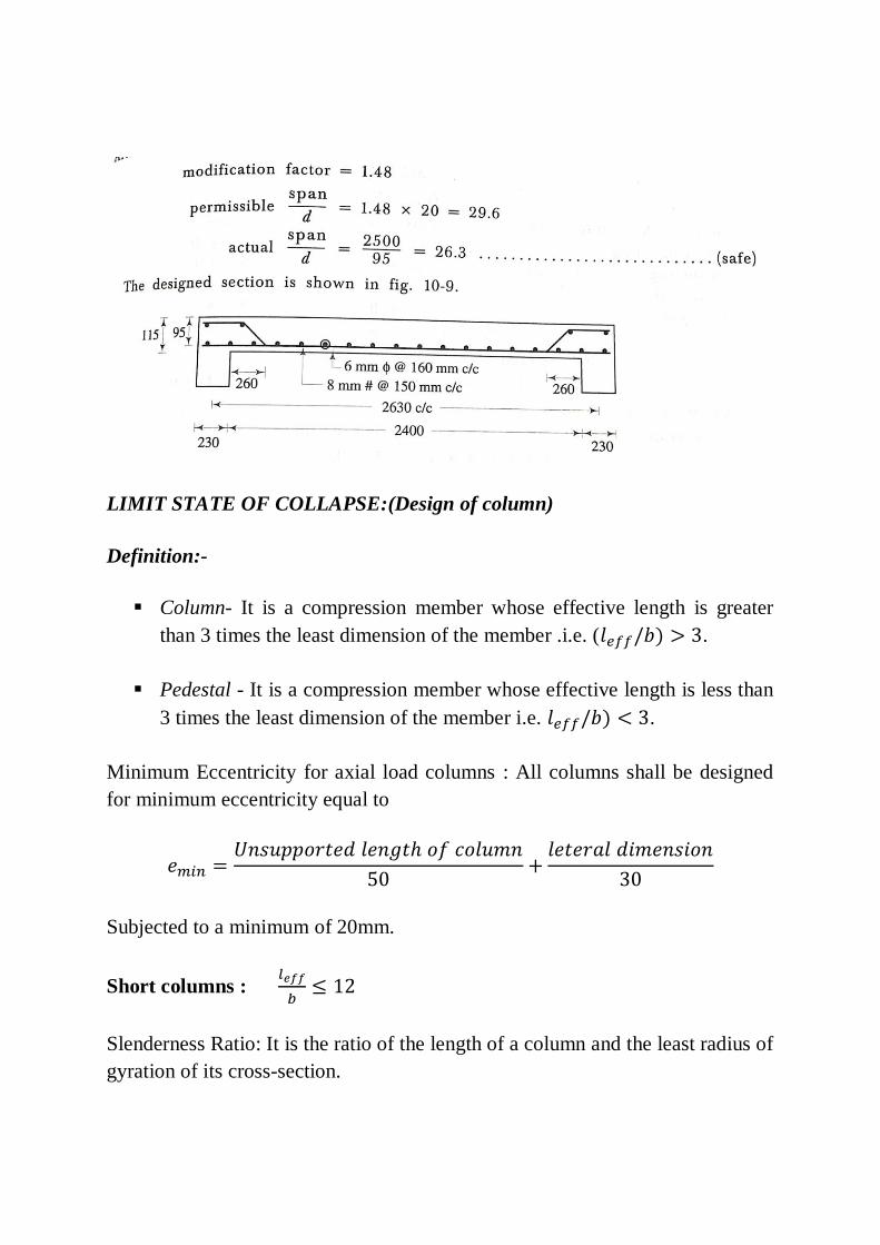
LIMIT STATE OF COLLAPSE:(Design of column)
Definition:-
Column- It is a compression member whose effective length is greater
than 3 times the least dimension of the member .i.e. ( .
Pedestal - It is a compression member whose effective length is less than
3 times the least dimension of the member i.e. .
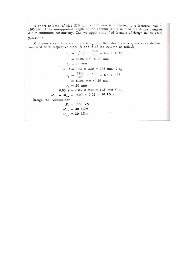
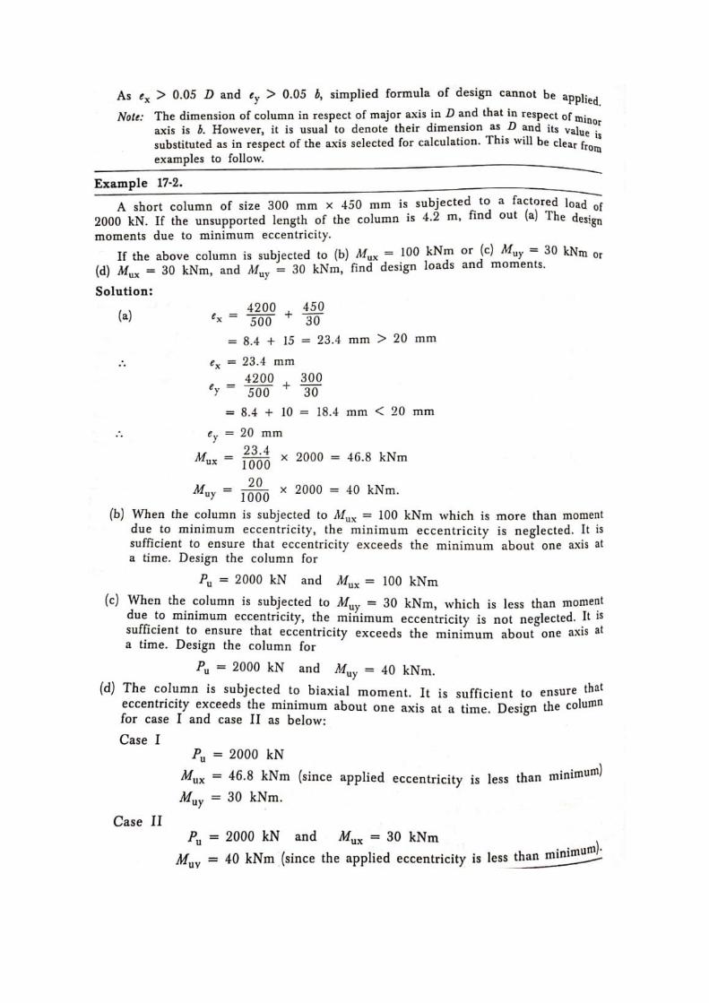
Minimum Eccentricity for axial load columns : All columns shall be designed
for minimum eccentricity equal to
Subjected to a minimum of 20mm.
Short columns :
Slenderness Ratio: It is the ratio of the length of a column and the least radius of
gyration of its cross-section.
Assumptions in the Design of Compression Members by Limit State of
Collapse:
It is thus seen that reinforced concrete columns have different classifications
depending on the types of reinforcement, loadings and slenderness ratios.
Detailed designs of all the different classes are beyond the scope here. Tied and
helically reinforced short and slender columns subjected to axial loadings with
or without the combined effects of uniaxial or biaxial bending will be taken up.
However, the basic assumptions of the design of any of the columns under
different classifications are the same.
I. The maximum compressive strain in concrete in axial compression is
taken as 0.002.
II. The maximum compressive strain at the highly compressed extreme fibre
in concrete subjected to axial compression and bending and when there is
no tension on the section shall be 0.0035 minus 0.75 times the strain at
the least compressed extreme fibre.
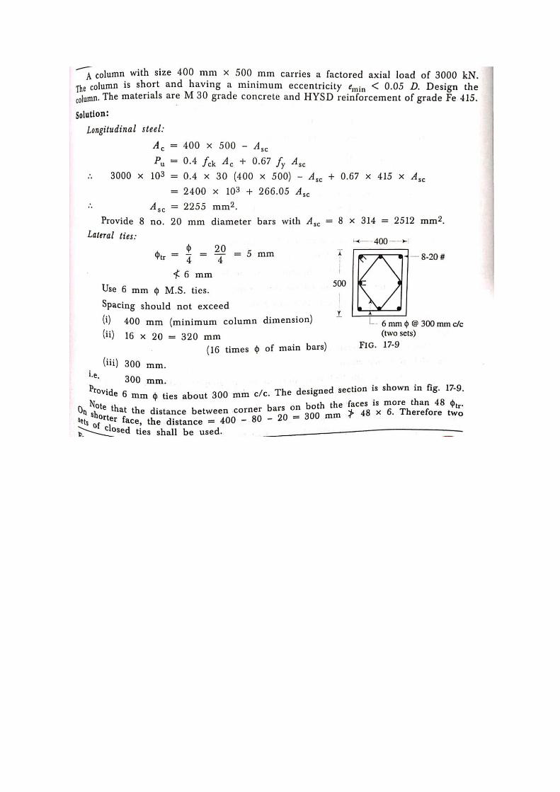
Longitudinal Reinforcement
The longitudinal reinforcing bars carry the compressive loads along with the
concrete. Following are the guidelines regarding the minimum and maximum
amount, number of bars, minimum diameter of bars, spacing of bars etc: The
minimum amount of steel should be at least 0.8 per cent of the gross cross-
sectional area of the column required if for any reason the provided area is more
than the required area.
(a) The maximum amount of steel should be 4 per cent of the gross
cross-sectional area of the column so that it does not exceed 6 per
cent when bars from column below have to be lapped with those in
the column under consideration.
(b) Four and six are the minimum number of longitudinal bars in
rectangular and circular columns, respectively.
(c) The diameter of the longitudinal bars should be at least 12 mm.
(d) Columns having helical reinforcement shall have at least six
longitudinal bars within and in contact with the helical
reinforcement. The bars shall be placed equidistant around its inner
circumference.
(e) The bars shall be spaced not exceeding 300 mm along the
periphery of the column.
(f) The amount of reinforcement for pedestal shall be at least 0.15 per
cent of the cross-sectional area provided.
Transverse Reinforcement
Transverse reinforcing bars are provided in forms of circular rings, polygonal
links (lateral ties) with internal angles not exceeding 135 or helical
reinforcement. The transverse reinforcing bars are provided to ensure that every
longitudinal bar nearest to the compression face has effective lateral support
against buckling. The salient points are:
Transverse reinforcement shall only go round corner and alternate bars if
the longitudinal bars are not spaced more than 75 mm on either side.
Longitudinal bars spaced at a maximum distance of 48 times the
diameter of the tie shall be tied by single tie and additional open ties for
in between longitudinal bars.
For longitudinal bars placed in more than one row (i) transverse
reinforcement is provided for the outer-most row in accordance with (a)
above, and (ii) no bar of the inner row is closer to the nearest
compression face than three times the diameter of the largest bar in the
inner row.
For longitudinal bars arranged in a group such that they are not in contact
and each group is adequately tied as per (a), (b) or (c) above appropriate,
the transverse reinforcement for the compression member as a whole may
be provided assuming that each group is a single longitudinal bar for
determining the pitch and diameter of the transverse reinforcement . The
diameter of such transverse reinforcement should not, however, exceed
20 mm .
Pitch and Diameter of Lateral Ties
(a) Pitch: The maximum pitch of transverse reinforcement shall be the least of
the following:
a. the least lateral dimension of the compression members;
b. sixteen times the smallest diameter of the longitudinal
reinforcement bar to be tied; and
c. 300 mm.
(b) Diameter: The diameter of the polygonal links or lateral ties shall be not less
than one-fourth of the diameter of the largest longitudinal bar, and in no case
less than 6 mm.
Helical Reinforcement
a) Pitch: Helical reinforcement shall be of regular formation with the turns
of the helix spaced evenly and its ends shall be anchored properly by
providing one and a half extra turns of the spiral bar. The pitch of helical
reinforcement shall be determined as given for all cases except where an
increased load on the column is allowed for on the strength of the helical
reinforcement. In such cases only,
The maximum pitch shall be the lesser of 75 mm
One-sixth of the core diameter of the column, and the minimum
pitch shall be the lesser of 25 mm and
Three times the diameter of the steel bar forming the helix.
Short columns with helical reinforcement:
The permissible load for columns with helical reinforcement shall be 1.05 times
the permissible load for similar members with ties.
i.e.
Where,
Short column subjected to uni-axial bending
Short columns with uni axial moment:
The maximum strain in concrete at the outermost compression fibre is 0.0035
when the N.A lies within the section and
In the limiting case when the N.A lies along the edge of the section, in the
latter case strain carries from 0.0035 at the highly compressed edge to
zero at the opposite edge.
For purely axial compression, the strain is assumed to be uniform and
equal to 0.002 across the section.
Slenderness limits for columns :
With bolt end restrained: Unsupported length should not be greater than
60 times lateral dimension.
If one end of column is unrestrained, unsupported length should not be
greater than 100 .
Numerical Problems
Limit state of serviceability: deflection
The serviceability requirement for the deflection should be such that neither the
efficiency nor appearance of a structure should be affected by the deflection
which will occur during its life.
Short- and Long-term Deflections
As per IS:456-2000
The following factors influence the short-term deflection of structures:
(i) magnitude and distribution of live loads
(ii) span and type of end supports,
(iii) cross-sectional area of the members,
(iv) amount of steel reinforcement and the stress developed in the
reinforcement,
(v) characteristic strengths of concrete and steel, and
(vi) amount and extent of cracking.
The long-term deflection is almost two to three times of the short-term
deflection. The following are the major factors influencing the long-term
deflection of the structures.
(i) humidity and temperature ranges during curing,
(ii) age of concrete at the time of loading, and
(iii) Type and size of aggregates, water-cement ratio, amount of compression
reinforcement, size of members etc., which influence the creep and
shrinkage of concrete.
Control of Deflection:
The maximum final deflection should not normally exceed span/250 due
to all loads including the effects of temperatures, creep and shrinkage and
measured from the as-cast level of the supports of floors, roof and all
other horizontal members.
The maximum deflection should not normally exceed the lesser of
span/350 or 20 mm including the effects of temperature, creep and
shrinkage occurring after erection of partitions and the application of
finishes.
It is essential that both the requirements are to be fulfilled for every structure.
Selection of Preliminary Dimensions
For the deflection requirements
Different basic values of span to effective depth ratios for three different
support conditions are prescribed for spans up to 10 m, which should be
modified under any or all of the four different situations:
(i) for spans above 10 m,
(ii) (ii) depending on the amount and the stress of tension steel
reinforcement,
(iii) (iii) depending on the amount of compression reinforcement, and
(iv) (iv) for flanged beams.
Basic values of span to effective depth ratios for spans upto 10 mt
Cantilever -7
Simply supported - 20
Contineous - 26
For lateral stability
The lateral stability of beams depends upon the slenderness ratio and the
support conditions.
For simply supported and continuous beams, the clear distance between
the lateral restraints shall not exceed the lesser of 60b or 250b2 /d, where
d is the effective depth and b is the breadth of the compression face
midway between the lateral restraints.
For cantilever beams, the clear distance from the free end of the
cantilever to the lateral restraint shall not exceed the lesser of 25b or
100b2 /d.
Deflection Due to Creep
Concrete creep is defined as: deformation of structure under sustained load.
Basically, long term pressure or stress on concrete can make it change shape.
This deformation usually occurs in the direction the force is being applied. Like
a concrete column getting more compressed, or a beam bending. Creep does not
necessarily cause concrete to fail or break apart. When a load is applied to
concrete, it experiences an instantaneous elastic strain which develops into
creep strain if the load is sustained.
Long term deflection in concrete is calculated by
Where θ ,being the creep coefficient,
Concrete Shrinkage : The volumetric changes of concrete structures due to the loss of
moisture by evaporation is known as concrete shrinkage or shrinkage of concrete. It is a
time-dependent deformation which reduces the volume of concrete without the impact of
external forces.
Concrete Footing:-
INTRODUCTION
Foundation is that part of a structure which transfers the load of the structure to soil on which
it rests. This term includes the portion of the structure below ground level (also known as
sub-structure) which provides a base for the structure above the ground (also known as super-
structure) as well as the extra provisions made to transmit the loads on the structure including
its self wt. to the soil below.
It is often misunderstood that the foundation is provided to support the load of the structure.
In fact, it is a media to transmit the load of the structure to the sub-soil. The objectives of
foundation are:
To distribute the weight of the structure over larger area so as to avoid over-loading of the soil beneath.
To load the sub – structure evenly and thus prevent unequal settlement.
To provide a level surface for building operations.
To take the sub-structure deep into the ground and thus increase its stability
preventing overturning.
Footings are an important part of foundation construction. They are typically made of
concrete with rebar reinforcement that has been poured into an excavated trench. The purpose
of footings is to support the foundation and prevent settling. Footings are especially important
in areas with troublesome soils.
Thickness at the edge of footing: In reinforced and plain concrete footing,the
thivkness at the edge shall be not less than 150 mmfor footings on soil
and not less than 300 mm for footing on piles.
The depth of foundation minimum of 500 mm.
Minimum % of steel: Footing is to be treated as an inverted slab. As per
IS:456-2000 the minimum % of steel is 0.12% of gross area with HYSD
bars and 0.15% of gross area with plain bars of mild steel.
Minimum clear cover: 50 mm. For any tipe of exposure condition.
TYPES OF FOUNDATIONS
Foundations can be broadly classified into two types:
(i) Deep foundations
(ii) Shallow foundations.
Deep foundations: When the foundations are placed considerably below the
lowest part of the super-structure it is termed as deep foundations. Pile
foundations, pier foundation, well foundation, cassions etc. fall in the category
of deep foundation.
(ii) Shallow foundations: When the foundation is placed immediately beneath
the lowest part of the super-structure it is termed as shallow foundation.
Shallow foundations can be broadly divided in the following groups:
(1) Spread footings
(2) Combined footings
(3) Mat or raft foundation.
Spread Footings
As the name suggest, in case of spread footings the base of the member (a
column or a wall) transmitting the load is made wider so as to distribute the load
over a larger area. A footing that supports a single column is known as isolated
column footing. In case of a wall, the footing has to be a continuous one and
hence it is known as wall footing or a continuous footing.
It is seen that square footing works out to be economical for square and circular
columns. Under rectangular column, rectangular footings are considered to be
more appropriate. In case the load on column is not large or the size of footing
works out to be small requiring small depth of footing it is desirable to keep the
thickness of footing uniform. In case the depth of the footing works out to be
more, it is common practice to gradually reduce the depth of the footings
towards the edges to achieve economy. The footing in such a case is termed as
sloped footings.
Combined Footings
A common footing provided for two or more columns in a row is known as
combined footing.
Mat or Raft Foundation
It is consist of thick reinforced concrete slab covering the entire area under a
supporting several columns and walls. It is the type of shallow foundation. It is
used in conditions where the soil bearing capacity is poor, and the loading to be
supported are from high columns or wall loads.
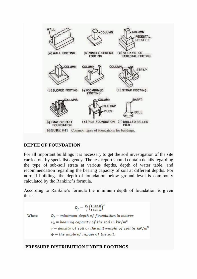
DEPTH OF FOUNDATION
For all important buildings it is necessary to get the soil investigation of the site
carried out by specialist agency. The test report should contain details regarding
the type of sub-soil strata at various depths, depth of water table, and
recommendation regarding the bearing capacity of soil at different depths. For
normal buildings the depth of foundation below ground level is commonly
calculated by the Rankine’s formula.
According to Rankine’s formula the minimum depth of foundation is given
thus:
PRESSURE DISTRIBUTION UNDER FOOTINGS
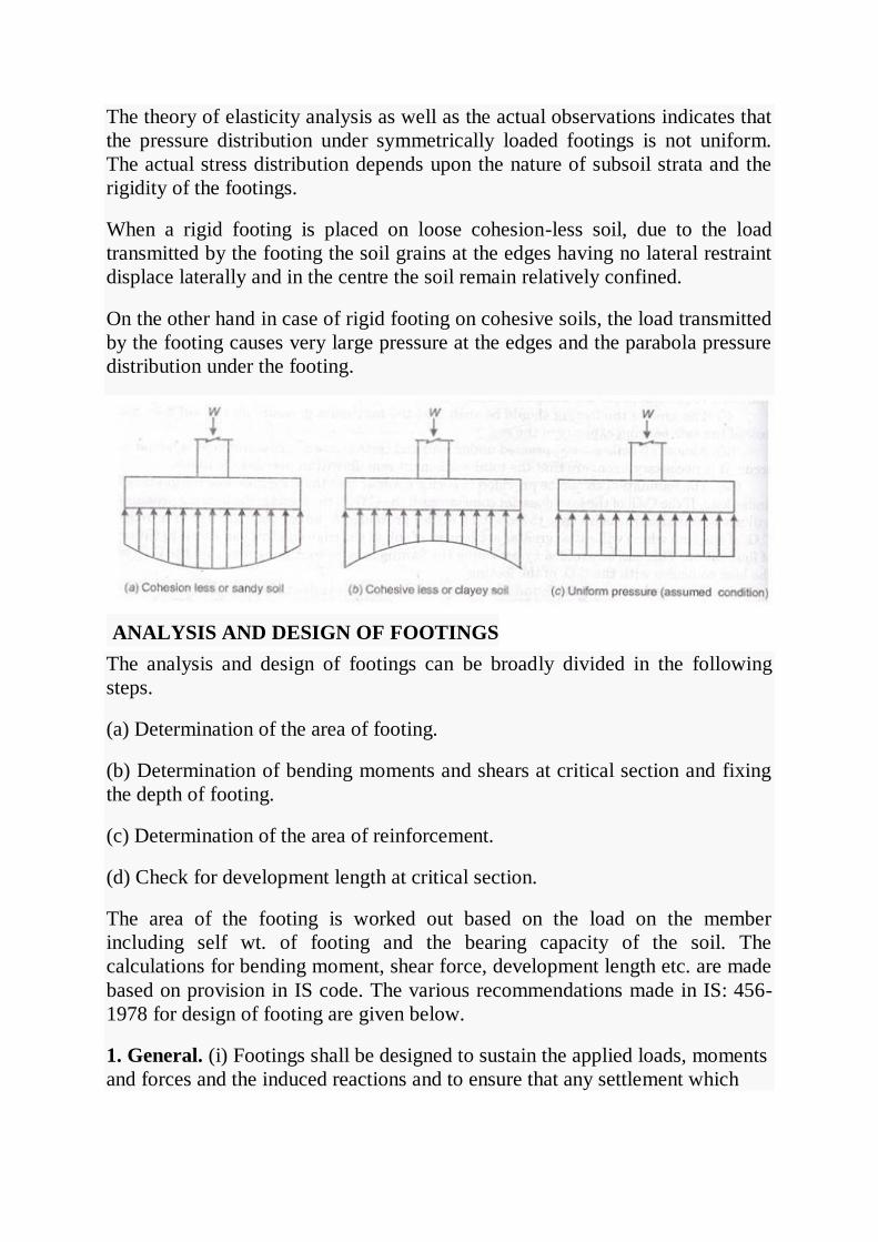
The theory of elasticity analysis as well as the actual observations indicates that
the pressure distribution under symmetrically loaded footings is not uniform.
The actual stress distribution depends upon the nature of subsoil strata and the
rigidity of the footings.
When a rigid footing is placed on loose cohesion-less soil, due to the load
transmitted by the footing the soil grains at the edges having no lateral restraint
displace laterally and in the centre the soil remain relatively confined.
On the other hand in case of rigid footing on cohesive soils, the load transmitted
by the footing causes very large pressure at the edges and the parabola pressure
distribution under the footing.
ANALYSIS AND DESIGN OF FOOTINGS
The analysis and design of footings can be broadly divided in the following
steps.
(a) Determination of the area of footing.
(b) Determination of bending moments and shears at critical section and fixing
the depth of footing.
(c) Determination of the area of reinforcement.
(d) Check for development length at critical section.
The area of the footing is worked out based on the load on the member
including self wt. of footing and the bearing capacity of the soil. The
calculations for bending moment, shear force, development length etc. are made
based on provision in IS code. The various recommendations made in IS: 456-
1978 for design of footing are given below.
1. General. (i) Footings shall be designed to sustain the applied loads, moments
and forces and the induced reactions and to ensure that any settlement which
may occur will be as nearly uniform as possible and the safe bearing capacity of
the soil is not exceed.
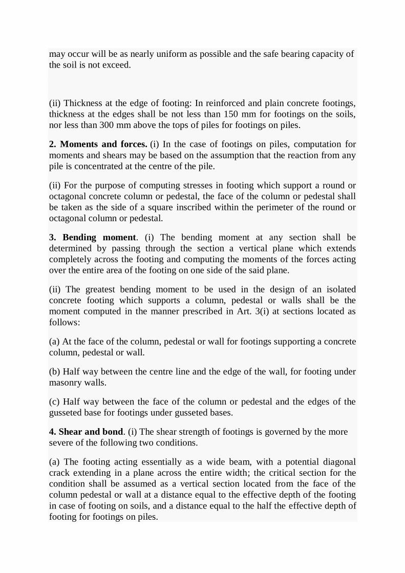
(ii) Thickness at the edge of footing: In reinforced and plain concrete footings,
thickness at the edges shall be not less than 150 mm for footings on the soils,
nor less than 300 mm above the tops of piles for footings on piles.
2. Moments and forces. (i) In the case of footings on piles, computation for
moments and shears may be based on the assumption that the reaction from any
pile is concentrated at the centre of the pile.
(ii) For the purpose of computing stresses in footing which support a round or
octagonal concrete column or pedestal, the face of the column or pedestal shall
be taken as the side of a square inscribed within the perimeter of the round or
octagonal column or pedestal.
3. Bending moment. (i) The bending moment at any section shall be
determined by passing through the section a vertical plane which extends
completely across the footing and computing the moments of the forces acting
over the entire area of the footing on one side of the said plane.
(ii) The greatest bending moment to be used in the design of an isolated
concrete footing which supports a column, pedestal or walls shall be the
moment computed in the manner prescribed in Art. 3(i) at sections located as
follows:
(a) At the face of the column, pedestal or wall for footings supporting a concrete
column, pedestal or wall.
(b) Half way between the centre line and the edge of the wall, for footing under
masonry walls.
(c) Half way between the face of the column or pedestal and the edges of the
gusseted base for footings under gusseted bases.
4. Shear and bond. (i) The shear strength of footings is governed by the more
severe of the following two conditions.
(a) The footing acting essentially as a wide beam, with a potential diagonal
crack extending in a plane across the entire width; the critical section for the
condition shall be assumed as a vertical section located from the face of the
column pedestal or wall at a distance equal to the effective depth of the footing
in case of footing on soils, and a distance equal to the half the effective depth of
footing for footings on piles.

(b) Two-way action of the footing with potential diagonal cracking along the
surface of truncated cone or pyramid around the concentrated load, in this case
the footing shall be designed for shear in accordance with appropriate provision
specified.
(ii) The critical section for checking the development length in a footing shall
be assumed at the same plane as those described for bending moment in Art. 3
and also at all other vertical planes where abrupt changes of section occur. If the
reinforcement is curtailed, the anchorage requirement shall be checked in
accordance with provision.
5. Tensile reinforcement. The total reinforcement at any section shall provide a
moment of resistance at least equal to the bending moment on the section
calculated in accordance with Art. 3.
(i) In one-way reinforced footing the reinforcement shall be distributed
uniformly across the full width of the footing.
(ii) In two-way reinforced square footing the reinforcement extending in each
direction shall be distributed uniformly across the full width of the footing.
(iii) In two-way reinforced rectangular footing, the reinforcement in the long
direction shall be distributed uniformly across the full width of the footing. For
reinforcement in the short direction, a central band equal to the width of the
footing shall be marked along the length of the footing and portion of the
reinforcement determined in accordance with equation given below shall be
uniformly distributed across the central band:
where β is the ratio of the long side to the short side of the footing. The
remainder of the reinforcement shall be uniformly distributed in the outer
portions of the footing.
6. Transfer of load at the base of column. The compressive stress in concrete
at the base of a column or pedestal shall be considered as being transferred by
bearing to the top of the supporting pedestal or footing. The bearing pressure on
the loaded area shall not exceed the permissible bearing stress in direct
compression multiplied by a value = but not greater than 2.
Where A1 supporting area for bearing of footing, which in sloped or stepped
footing may be taken as the area of the lower base of the largest frustum of a
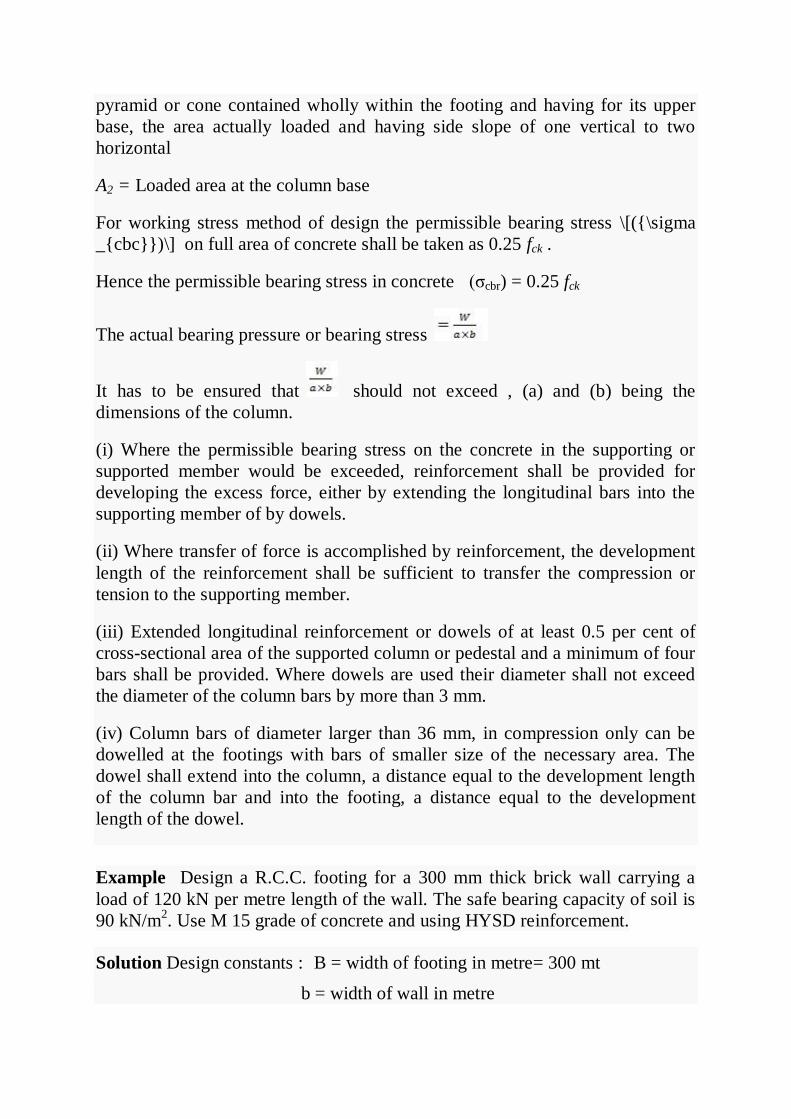
pyramid or cone contained wholly within the footing and having for its upper
base, the area actually loaded and having side slope of one vertical to two
horizontal
A2 = Loaded area at the column base
For working stress method of design the permissible bearing stress \[({\sigma
_{cbc}})\] on full area of concrete shall be taken as 0.25 fck .
Hence the permissible bearing stress in concrete (σcbr) = 0.25 fck
The actual bearing pressure or bearing stress
It has to be ensured that should not exceed , (a) and (b) being the
dimensions of the column.
(i) Where the permissible bearing stress on the concrete in the supporting or
supported member would be exceeded, reinforcement shall be provided for
developing the excess force, either by extending the longitudinal bars into the
supporting member of by dowels.
(ii) Where transfer of force is accomplished by reinforcement, the development
length of the reinforcement shall be sufficient to transfer the compression or
tension to the supporting member.
(iii) Extended longitudinal reinforcement or dowels of at least 0.5 per cent of
cross-sectional area of the supported column or pedestal and a minimum of four
bars shall be provided. Where dowels are used their diameter shall not exceed
the diameter of the column bars by more than 3 mm.
(iv) Column bars of diameter larger than 36 mm, in compression only can be
dowelled at the footings with bars of smaller size of the necessary area. The
dowel shall extend into the column, a distance equal to the development length
of the column bar and into the footing, a distance equal to the development
length of the dowel.
Example Design a R.C.C. footing for a 300 mm thick brick wall carrying a
load of 120 kN per metre length of the wall. The safe bearing capacity of soil is
90 kN/m2. Use M 15 grade of concrete and using HYSD reinforcement.
Solution Design constants : B = width of footing in metre= 300 mt
b = width of wall in metre
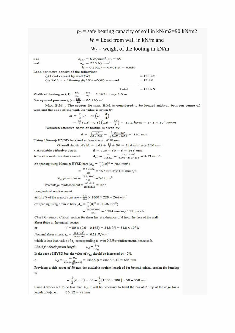
p0 = safe bearing capacity of soil in kN/m2=90 kN/m2
W = Load from wall in kN/m and
W1 = weight of the footing in kN/m

THANK YOU