self-q-switching phase-conjugation nd:yag laser with a stimulated-brillouin-scattering mirror
TRANSCRIPT
2102 J. Opt. Soc. Am. B/Vol. 21, No. 12 /December 2004 Su et al.
Self-Q-switching phase-conjugation Nd:YAG laserwith a stimulated-Brillouin-scattering mirror
Hong Su
Department of Physics, National University of Singapore, Singapore 119260;Anhui Institute of Optics and Fine Mechanics, the Chinese Academy of Sciences, China 230031
Sing-hai Tang and Yi-qiang Qin
Department of Physics, National University of Singapore, Singapore 119260
Wei-jun Zhang and An-ling Liu
Anhui Institute of Optics and Fine Mechanics, the Chinese Academy of Sciences, China 230031
Received December 26, 2003; revised manuscript received May 26, 2004; accepted July 13, 2004
We present a numerical and experimental study of a self-Q-switching phase-conjugation Nd:YAG laser oscil-lator with a stimulated-Brillouin-scattering mirror. Q-switching is provided only by a nonlinear liquid in thecavity without further need for any shutter. During the stimulated-Brillouin-scattering process, throughswitching by intracavity radiation, laser beam spot-size widening occurs because of imperfect phase conjuga-tion. It is demonstrated that the results of numerical simulation of the intracavity photon number, pulse du-ration, and laser beam spot size at the output coupling mirror for the laser are comparable with those observedexperimentally. © 2004 Optical Society of America
OCIS codes: 140.3540, 140.3530, 140.3410, 290.5900, 190.5040.
1. INTRODUCTIONIt is well known that the beam quality of high-powersolid-state lasers can be adversely affected by the static-state phase defect or the transient thermal-lens effect.In recent years, there has been more and more interest inthe application of the phase-conjugation (PC) techniquebased on stimulated Brillouin scattering (SBS) to enhancethe performance of pulsed laser resonators.1–3 In suchan application, the rear mirror of a conventional laserresonator is replaced by a phase-conjugation mirror(PCM). Since high light intensities are necessary toreach the SBS threshold for switching on the PCM, it hasbeen customary to use a starter laser cavity to switch onthis phase-conjugation resonator4–7 (PCR). However, la-ser alignment is complicated by the requirement of plac-ing the lens in the starter cavity.
In this paper, we describe a PCR laser that does not re-quire a starter cavity or any shutter, as depicted in Fig. 1.Besides easier laser alignment and simple, precise posi-tioning, the PCR laser has an advantage over conven-tional design, that the SBS cell functions either as a non-linear PCM or as a self-Q-switching mirror. Comparedwith conventional Q-switching materials, this self-Q-switching design is not limited by laser wavelength andhas a high damage threshold. The stronger the intracav-ity intensity is, the higher is the reflection coefficient forthe PCR, and hence the narrower is the laser pulse dura-tion. The present work is an attempt to design an opti-mal PCR laser, taking into realistic consideration damagein optical components and imperfect phase conjugation.An explanation is presented for the dynamics of intracav-
0740-3224/2004/122102-05$15.00 ©
ity photon number, the dynamics of the incident laserbeam spot size, and the reflection coefficient at PCM inthe self-Q-switching PCR laser.
2. PROPERTY OF LASER BEAM AT THEOUTPUT COUPLING MIRROROur experimental setup for the PCR laser is shown in Fig.1(a), where M1 is the output coupling mirror and PCM isthe rear cavity mirror consisting of a SBS mirror. TheNd:YAG crystal has a length of l3 and refractive index ofna for the active medium (AM). The aperture is a pinholewith radius of dph , L is the lens with focal length f, li (i5 1,2,4,5) is the actual distance between the two neigh-
boring optical components, and Lc is the total length ofthe PCR. Assuming a Gaussian beam, the single-passtransmission matrix from M1 to PCM, excluding thesetwo end-cavity mirrors, can be obtained as
M 5 Fa b
c dG 5 F1 l1
0 1 GF1 0
21/f 1GF1 l2
0 1 G3 F1 l3 /na
0 1 GF1 l4
0 1 GF1 0
2il/pdph2 1GF1 l5
0 1 G ,(1)
which is the matrix shown symbolically in Fig. 1(b). Fig-ure 1(b) shows a simple theoretical model for our PCR la-ser, in which 1/q1i and 1/q1r , 1/q2i and 1/q2r , are complexcurvatures of the incident and reflected wave fronts at M1and PCM, respectively. Note that on the same condition,
2004 Optical Society of America

Su et al. Vol. 21, No. 12 /December 2004 /J. Opt. Soc. Am. B 2103
the single-pass transmission matrix from PCM to M1 isthe commutative matrix of M, which will be used below.
However, the spot size of the phase-conjugation beamreflected by the PCM becomes smaller than that of the in-cident beam owing to threshold limitation during the SBSgeneration process. While the curvature radius of the re-flected beam (R2r 5 2R2i) remains the same as that ofthe incident beam with its transmission in the reverse di-rection owing to the phase-conjugation effect, and its spotsize (beam radius) W2r 5 bW2i is reduced at the PCM,where b is a relative beam-waist parameter (b , 1 for animperfect PCM, whereas b 5 1 for an ideal PCM). Thusby considering the phase-conjugation effect and thresholdlimitation, the transmission matrix for a real PCM can beexpressed as the parameters of the incident beam at thePCM:
MPCM 5 F1 0
22/R2i 2 il~1 2 b2!/pb2W2i2 1G . (2)
As such a SBS-PCM may be considered either as a reflect-ing mirror with quasi-Gaussian distribution or a soft-edgediaphragm for limiting the transverse mode in the cavity.Thus a single transverse mode with quasi-Gaussian dis-tribution can be obtained in such a phase-conjugationresonator. However, the relative beam-waist parameterand reflection coefficient at PCM depend strongly on theintracavity light intensity. The SBS phase-conjugationlight will be actuated when the intracavity incident inten-sity at PCM reaches beyond SBS threshold.
Taking the incident plane of the PCM as a referenceplane, when the incident beam is first reflected by PCMand then reaches the PCM again through M1 , its corre-sponding ABCD matrix for round-trip pass of a Gaussianbeam is given by using Eqs. (1) and (2):
Fig. 1. Phase-conjugation resonator with a SBS mirror: (a) ex-perimental setup, (b) theoretical model.
M2 5 FA B
C DG 5 Fa b
c dGF1 0
22/r1 1GFd b
c aG3F1 0
22/R2i 2 il~1 2 b2!/pb2W2i2 1G , (3)
where r1 is curvature radius of M1 . According to thetheory of an optical resonant cavity, the complex curva-ture of the wave front of the incident beam at PCM keepsthe same value through the round-trip pass in the PCRand is described as
q2i~W2i , R2i! 5 ~Aq2i 1 B !/~Cq2i 1 D !, (4)
where 1/q2i 5 1/R2i 2 il/pW2i2 is the complex curvature
of the wave front at the input of PCM. Hence W2i andR2i can be obtained from the above Eqs. (1)–(4), and fur-thermore, the input beam spot size and its curvature ra-dius at M1 can be deduced through the ABCD law. Asan example, consider the design parameters given by theset l5 5 400 mm, l4 5 100 mm, l3 5 110 mm, l25 200 mm, and refractive index na 5 1.82 of Nd:YAG at1064 nm. The input beam spot sizes at M1 under variousconditions are shown in Figs. 2 and 3. Figure 2(a) showsthat the input beam spot size W1i at M1 in the PCR with-
Fig. 2. (a) Input beam spot size at M1 versus b with apertureand no aperture; (b) input beam spot size at M1 versus the diam-eter of the pinhole dph .

2104 J. Opt. Soc. Am. B/Vol. 21, No. 12 /December 2004 Su et al.
out the aperture reduces sharply with an increase in therelative beam-waist parameter b, which is consistentwith that of Ref. 8, while the beam spot size W1i in thePCR with the aperture is nearly independent of b. Fig-ure 2(b) shows W1i as a function of pinhole in the PCRwith the aperture. W1i first decreases with an increasein the diameter of the pinhole dph and slowly approachesto a small value. It is seen that the spot size changesonly by a small margin when the diameter of the pinholeis more than 0.2 mm for both the ideal case of b 5 1 andthe nonideal case of b 5 0.5. According to Ref. 8, the in-tracavity intensity is near the threshold, and b is verysmall when the spot size at M1 is much larger. In Fig. 3,in the case of the ideal PC with b 5 1, it is seen that theinput beam spot size W1i at M1 in the PCR with no aper-ture is more sensitive to the distance l1 between the lensand the center of the SBS cell than the case (the fixedvalue 2 mm) of the PCR with an aperture of diameter0.192 mm. As the spot size W1i remains small through-out, in order to avoid the damage to the optical compo-nents that has been mentioned in Ref. 9, l1 is chosen to benearly less than or equal to f. Whereas in the case ofnonideal PC with b 5 0.5, the variation of W1i in the PCR
Fig. 3. Input beam spot size at M1 versus l1 and f with no ap-erture.
with no aperture is quite different from that of the idealPC, except for a short segment when l1 lies just above thefocal length f.
3. SELF-Q-SWITCHING WITH A SBSPHASE-CONJUGATION MIRRORIn a realistic evaluation of the output parameters employ-ing PCR, because of imperfect phase conjugation, one hasto take into account the changes in the beam cross sectionduring the formation of a giant pulse. The set of differ-ential equations that describes such a laser with a SBScell as the rear mirror, and at the same time incorporatesthe nonlinear variations in the laser beam spot size, maybe written as1,8,10
dN/dt 5 c1NMa /S 2 N@ln~1/r1r2! 1 a0#/tR ,
dMa /dt 5 2c1dNMa /S 1 maladS/dt,
dS/dt ' DS/Dt 5 H S~1/b2 2 1 !/tR ~S < SAM!,
0 ~S . SAM!,(5)
where Eqs. (5) describe the evolution of the intracavityphoton number N, the rate for the population inversionMa in AM, and the temporal evolution of the beam spotsize cross section S owing to the SBS process in a phase-conjugation mirror, respectively. Here, c1 5 2sa /tR(where sa is the lasing cross section of AM) is a couplingparameter between the photon number and the popula-tion inversion Ma ; r1 and r2 are the reflection coefficientsof M1 and PCM; a0 is the nonresonant losses in all cavitycomponents, while ln(1/r1r2) is the useful losses on thecavity mirrors; tR 5 2Lc /c is the round-trip time for acavity of length Lc and velocity of light c; d represents thereduction factor in the population inversion in the AM;ma and la are concentration and length of AM; SAM is theAM cross section, respectively. Here it is to be borne inmind that both b and r2 are functions of intracavity pho-ton number (intracavity incident intensity) at the PCM.8
In particular, r2 is nonzero only when the intracavity in-cident intensity exceeds the SBS pump threshold suchthat the SBS phase-conjugation light can be generated.As r2 increases, the laser will have sustained outputwhen the gain is larger than the total loss in the cavity.
Consider next the assembly of the focal lens and theSBS cell. It is to be noted that the spot size of the SBSlight at the lens is also widened owing to imperfect phaseconjugation, as described by the rated third equation inEqs. (5). We ignored the small Stokes frequency shift ofSBS, as it is still within the coverage of the gain linewidthof the active medium, where the laser beam remains inthe laser cavity for only a few round trips. Moreover, thebroader is the widened spot size at the lens, the larger isthe geometrical losses of the cavity. The losses can be se-vere when the AM begins to assume some aperturingproperties. When the cross section SAM of the active me-dium is compared with the beam spot size cross section S,the SBS reflection coefficient r2 is rewritten as
r2 5 H rsbsmax ~S , SAM!
rsbsmax exp~21/b2! ~S . SAM!
. (6)
Su et al. Vol. 21, No. 12 /December 2004 /J. Opt. Soc. Am. B 2105
The SBS reflection coefficient, for which the steady-statevalue was assumed, is computed from the formula for thegain8:
xN 5 gBIL 5 $G 1 ln@rsbs~1 2 rsbs! 1 exp~2G !#%/~1
2 rsbs!, (7)
where G ' 25 is related to the initial Stokes noise level,gB is the gain of the SBS cell, and L is the effective inter-action length (that is, a confocal parameter), which de-pends on the radiation focusing inside the cell. And x5 4Ghv/ltR , I 5 I0 exp(22x2/Wi
2) is an incident inten-sity on the cell, where hv is single photon energy, l is la-ser wavelength, I0 is its maximum value, and x is the co-ordinate across the beam spot size. For the reflectionbeam at PCM, we take the SBS reflection coefficient inthe maximum of the output beam as rsbs
max 5 r2 , and rela-tive beam waist parameter b 5 Wr /Wi . During the SBSprocess, intracavity loss will break from infinity (r2' 0) to small value (r2 ' 1); thus a self-Q-switchingpulse will be generated. The higher r2 of PCM is, thenarrower the giant pulse width is.
4. NUMERICAL AND EXPERIMENTALRESULTSIn our experimental arrangement as shown in Fig. 1(a),the active medium consists of a Nd:YAG rod (diameter of7.0 mm, length of 110 mm) pumped by two xenon flashlamps insider a water-cooled double-elliptical cavity, andthe SBS mirror consists of an acetone-filled cell (diameterof 30.0 mm, length of 100 mm) along with a 100-mm focallens, where the cross section of the cell is larger than thefocusing area of the focused beam and the repetition rate(1 Hz) for the phase-conjugation laser is very low; we ig-nore thermal effect and the generation of the bubbles inthe cell. The other parameters of the PCR are the sameas those of Ref. 8, where r1 5 0.04, and the initial value ofthe SBS reflection coefficient r2 5 0 when there is no las-ing in the cavity by tilting the SBS cell and lens.
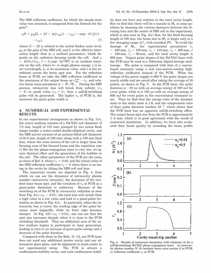
The numerical results are depicted in Fig. 4, fromwhich we can see the dynamics of intracavity photonnumber (intracavity intensity), the dynamics of the inci-dent laser beam spot, and the variation of r2 at PCM as agiant-pulse formation is underway. Because of theswitching on of the PCM by intracavity radiation as seenfrom Fig. 4(c) (a0 5 0.01), the total loss will switch froma high value to a low value and lead to a giant-pulse for-mation as shown in Fig. 4(a). In particular, when the in-tracavity loss is lower, the trailing edge of the pulse be-comes more laggardly, while its front edge becomessharper. In Fig. 4(b) (a0 5 0.01), one can see that thespot size increases sharply when it is close to the PCMswitching threshold. Thus an additional area of the ac-tive medium begins to participate in laser generation,leading in turn to an increase of giant-pulse energy and adecrease of the pulse duration.
Compared with those in the Refs. 11–14, our PCR laserdoes not need any additional starter cavity and any at-tenuation glass plate, and its alignment is much easier inour experimental setup. The PCR is always aconfinement-stability cavity, and such confinement stabil-
ity does not have any relation to the total cavity length.But we find that there will be a macula in M1 in some po-sitions by choosing the various distances between the fo-cusing lens and the center of SBS cell in the experiment,which is also seen in Fig. 3(a) that, for the fixed focusinglength of 100 mm, the beam size in M1 is larger only in afew changing range of l1 with nonideal PC. To avoid thedamage of M1 , the experimental parameters l55 400 mm, l4 5 100 mm, l3 5 110 mm, l2 5 200 mm, f5 100 mm, l1 5 90 mm, and the total cavity length is900 mm. Output pulse shapes of the Nd:YAG laser withthe PCR may be read in a Tektronix digital-storage oscil-loscope. The pulse is compared with that of a conven-tional resonator using a real rear-mirror-coating high-reflection coefficient instead of the PCM. When thevoltage of the power supply is 900 V, the pulse shapes arenearly stable and are saved after taking the average of 16pulses, as shown in Fig. 5. In the PCR laser, the pulseduration is ;30 ns with an average energy of 100 mJ forevery pulse, while it is 150 ms with an average energy of600 mJ for every pulse in the conventional resonator la-ser. Thus we find that the energy ratio of the dynamicstate to the static state is 1:6, and the compression ratioof their pulse duration reaches 1024, which shows thatthe PCR laser has an apparent self-Q-switching effect.The output beam spot size from the PCR is approximately1–2 mm, which is in good agreement with the result ofnumerical simulation. In addition, we have also evalu-ated their beam quality by recording the beam profile
Fig. 4. Results of numerical simulation with relations (4) for aself-Q-switching Nd:YAG phase-conjugation laser: (a) intracav-ity photon number N; (b) incident beam cross section S at PCM;(c) reflection coefficient r2 at PCM.

2106 J. Opt. Soc. Am. B/Vol. 21, No. 12 /December 2004 Su et al.
with a CCD camera. The M2 value for the PCR Nd:YAGlaser is 1.2, whereas the one for the conventional resona-tor Nd:YAG laser is 2.05, which verifies again that thePCR can remove the phase distortion and improve the la-ser beam quality.
5. CONCLUSIONIn summary, the self-Q-switching Nd:YAG laser with aSBS PCM is optimized by considering the effect of beamspot-size widening owing to imperfect phase conjugation.The self-Q-switching phase-conjugation Nd:YAG laser can
Fig. 5. (a) Pulse shape of Nd:YAG laser with the PCR; (b) pulseshape of Nd:YAG laser with a conventional resonator.
be operated in TEM00 mode with 100-mJ output energy ata repetition rate of 1 Hz. And good agreement is ob-served between the theory and the experiments. In par-ticular, damage of optical components may be avoided bychoosing appropriate PCR parameters in the experimen-tal laser setup.
REFERENCES1. A. E. Siegman, P. A. Belanger, and A. Hardy, Optical Phase
Conjugation, R. A. Fisher, ed. (Academic, New York, 1983),Chap. 13.
2. K. Viliam, F. Henryk, A. A. Alexander, J. W. Klaus, D. Hi-royuki, F. Hisanori, N. Masahiro, and Y. Tatsuhiko, ‘‘Reli-able stimulated Brillouin scattering compression ofNd:YAG laser pulses with liquid fluorocarbon for long-timeoperation at 10 Hz,’’ Appl. Opt. 37, 7085–7090 (1998).
3. M. J. Damzen, V. I. Vlad, V. Babin, and A. Mocofanescu,Stimulated Brillouin Scattering Fundamentals and Appli-cations (Institute of Physics, London, 2003).
4. N. N. Il’ichev, A. A. Malyutin, and P. P. Pashinin, ‘‘Laserwith diffraction-limited divergence and Q-switching bystimulated Brillouin scattering,’’ Sov. J. Quantum Electron.12, 1161–1164 (1982).
5. M. M. Denariez-Roberge and G. Giuliani, ‘‘High-powersingle-mode laser operation using stimulated Rayleigh scat-tering,’’ Opt. Lett. 6, 339–341 (1981).
6. G. Giuliani, M. M. Denariez-Roberge, and P. A. Belanger,‘‘Transverse modes of a stimulated scattering phase conju-gate resonator,’’ Appl. Opt. 21, 3719–3724 (1982).
7. H. J. Eichler, A. Haase, S. Hermann, R. Menzel, and D.Schumann, ‘‘Beam quality improvement of pulsed Nd:YAG-lasers using Brillouin phase conjugation,’’ Proc. SPIE 1834,176–183 (1992).
8. A. V. Kir’yanov, V. Aboites, and N. N. Il’ichev, ‘‘Analysis of alarge-mode neodymium laser passively Q switched with asaturable absorber and a stimulated-Brillouin-scatteringmirror,’’ J. Opt. Soc. Am. B 17, 11–17 (2000).
9. Yang Jingguo and Jiang Hongwei, ‘‘Self-Q-switchingNd:YAG laser operation using stimulated thermal Rayleighscattering,’’ Opt. Quantum Electron. 26, 929–932 (1994).
10. A. Agnesi and G. C. Reali, ‘‘Passive and self-Q-switching ofphase conjugation Nd:YAG laser oscillators,’’ Opt. Commun.89, 41–46 (1992).
11. H. Meng, V. Aboites, and H. J. Eichler, ‘‘Q-switched Nd:YAGlaser by SBS,’’ presented at the Lasers ’90 InternationalConference, San Diego, Calif., December 10–14, 1990.
12. H. Meng, V. Aboites, and H. J. Eichler, ‘‘SBS Q-switchedNd:YAG laser,’’ Rev. Mex. Fis. 36, 335–339 (1990).
13. N. N. Ilichev, A. V. Kiryanov, A. A. Malyutin, P. P. Pashinin,V. S. Sidorin, and E. I. Shklovskii, ‘‘Passive Q switching of a1.3-mm laser resonator using a stimulated Brillouin scatter-ing mirror,’’ Sov. J. Quantum Electron. 20, 1383–1384(1990).
14. H. Meng, V. Aboites, and H. J. Eichler, ‘‘Characterization ofa Nd:YAG phase conjugated laser,’’ Rev. Mex. Fis. 38, 427–431 (1992).