self-propelled scissor lifts - master hire · zhejiang dingli machinery co., ltd. 2014-03 ......
TRANSCRIPT

SELF-PROPELLED SCISSOR LIFTS
OPERATOR’S MANUAL with Maintenance Information
( For S0608EH, S0808EH, S0812EH, S1012EH, S1212EH, S1412EH ) ( For S0608E, S0808E, S0812E, S1012E, S1212E, S1412E )
( Hydraulic Motor / DC Motor Drive )
(Series 3)
Part Number: SM0110111A
Zhejiang Dingli Machinery Co., Ltd. 2014-03
WARNINGTHE MANUFACTURER SHALL NOT BE HELD LIABLE IN CASE OF FAULTSOR ACCIDENTS DUE TO NEGLIGENCE, INCAPACITY, INSTALLATION BYUNQUALIFIED TECHNICIANS AND IMPROPER USE OF THE MACHINE
DO NOT OPERATE THIS MACHINE UNTIL YOU READ AND UNDERSTANDALL THE DANGERS,WARNINGS AND CAUTIONS IN THIS MANUAL

OPERATOR’S MANUAL with Maintenance Information
Version of the Record
i
Version of the Record
Version Number Create Date
SM0110111A_Rev1.0 …………………………………………………………………………… 2014-03


OPERATOR’S MANUAL with Maintenance Information
i
Important
Read, understand and obey these safety rules
and operating instructions before operating
this machine.
Only trained and authorized personnel shall be
permitted to operate this machine. This
manual should be considered a permanent
part of your machine and should remain with
the machine at all times. If you have any
questions, please call DINGLI Machinery.
Contents Page
Safety Rules 1
Legend 9
Decals 10
Specifications 19
Control panel 31
Pre-operation Inspection 34
Workplace Inspection 36
Function Tests 37
Operating Instructions 41
Transport and Lifting Instructions 51
Maintenance 55
Schematic 83
Inspection and Repair Log 89
Owners, Users and operators:
We appreciate your choice of our machine for
your application. Our number one priority is
user safety, which is best achieved by our joint
efforts. We feel that you make a major
contribution to safety if you, as the equipment
users and operators:
1 Comply with employer, job site and
governmental rules.
2 Read, understand and follow the
instructions in this and other manuals
supplied with this machine.
3 Use good safe work practices in a
commonsense way.
4 Only have trained / certified operators,
directed by informed and knowledgeable
supervision, running the machine.
If there is anything in this manual that is not
clear or which you believe should be added,
please contact us.
Contact us:
Zhejiang Dingli Machinery Co., Ltd.
1255 Baiyun South Road. Leidian Town.
Deqing Zhejiang
China
Tel: +86-572-8681688
Fax: +86-572-8681690
Web: www.cndingli.com
E-mail:[email protected]

OPERATOR’S MANUAL with Maintenance Information
Safety Rules
1
Danger
Failure to obey the instructions and
safety rules in this manual will
result in death or serious injury.
Do Not Operate Unless:
√ You learn and practice the principles of
safe machine operation contained in this
operator's manual.
1 Avoid hazardous situations.
Know and understand the safety rules
before going on to the next section.
2 Always perform a pre-operation
inspection.
3 Always perform function tests prior to
use.
4 Inspect the workplace.
5 Only use the machine as it was
intended.
√ You read, understand and obey the
manufacturer's instructions and safety
rules— safety and operator's manuals and
machine decals.
√ You read, understand and obey employer's
safety rules and worksite regulations.
√ You read, understand and obey all
applicable governmental regulations.
√ You are properly trained to safely operate
the machine.
Decal Legend
DINGLI product decals use symbols, color
coding and signal words to identify the
following:
Safety alert symbol—used to alert
personnel to potential personal injury hazards.
Obey all safety messages that follow this
symbol to avoid possible injury or death.
Red—used to indicate the
presence of an imminently hazardous situation
which, if not avoided, will result in death or
serious injury.
Orange—used to indicate the
presence of a potentially hazardous situation
which, if not avoided, could result in death or
serious injury.
Yellow with safety alert
symbol- used to indicate the presence of a
potentially hazardous situation which, if not
avoided, may cause minor or moderate injury.
Blue without safety alert
symbol—used to indicate the presence of a
potentially hazardous situation which, if not
avoided, may result in property damage.

OPERATOR’S MANUAL with Maintenance Information
Safety Rules
2
Intended Use
This machine is intended to be used only to lift
personnel, along with their tools and materials
to an aerial work site.
Safety Sign Maintenance
Replace any missing or damaged safety signs.
Keep operator safety in mind at all times. Use
mild soap and water to clean safety signs. Do
not use solvent-based cleaners because they
may damage the safety sign material.
Electrocution Hazard
This machine is not electrically insulated and
will not provide protection from contact with or
proximity to electrical current.
Maintain safe distances from electrical power
lines and apparatus in accordance with
applicable governmental regulations and the
following chart.
Voltage Phase to Phase
Minimum Safe Approach Distance
Meters
0 to 300V Avoid Contact
300V to 50KV 3.05
50KV to 200KV 4.60
200KV to 350KV 6.10
350KV to 500KV 7.62
500KV to 750KV 10.67
750KV to 1000KV 13.72
Allow for platform movement, electrical line
sway or sag and beware of strong or gusty
winds.
Keep away from the machine if it contacts
energized power lines. Personnel on the
ground or in the platform must not touch or
operate the machine until energized power
lines are shut off.
Do not operate the machine during lightning or
storms.
Do not use the machine as a ground for
welding.
Tip-over Hazard
Occupants, equipment and materials must not
exceed the maximum platform capacity or the
maximum capacity of the platform extension.
Maximum capacity – S0608EH
Maximum occupants (Indoor use) 2
Maximum occupants (Outdoor use) 1
Platform allowable maximum load 380kg
Extension deck allowable maximum load 113kg
Maximum capacity – S0808EH
Maximum occupants (Indoor use ONLY) 2
Platform allowable maximum load 230kg
Extension deck allowable maximum load 113kg
Maximum capacity – S0812EH
Maximum occupants (Indoor / Outdoor use) 2
Platform allowable maximum load 450kg
Extension deck allowable maximum load 113kg
Maximum capacity – S1012EH
Maximum occupants (Indoor use) 2
OPERATOR’S MANUAL with Maintenance Information
Safety Rules
3
Maximum occupants (Outdoor use) 1
Platform allowable maximum load 320kg
Extension deck allowable maximum load 113kg
Maximum capacity – S1212EH
Maximum occupants (Indoor use ONLY) 2
Platform allowable maximum load 320kg
Extension deck allowable maximum load 113kg
Maximum capacity – S1412EH
Maximum occupants (Indoor use ONLY) 2
Platform allowable maximum load 200kg
Extension deck allowable maximum load 113kg
Maximum capacity – S0608E
Maximum occupants (Indoor use) 2
Maximum occupants (Outdoor use) 1
Platform allowable maximum load 380kg
Extension deck allowable maximum load 113kg
Maximum capacity – S0808E
Maximum occupants (Indoor use ONLY) 2
Platform allowable maximum load 230kg
Extension deck allowable maximum load 113kg
Maximum capacity – S0812E
Maximum occupants (Indoor/Outdoor use) 2
Platform allowable maximum load 450kg
Extension deck allowable maximum load 113kg
Maximum capacity – S1012E
Maximum occupants (Indoor use) 2
Maximum occupants (Outdoor use) 1
Platform allowable maximum load 320kg
Extension deck allowable maximum load 113kg
Maximum capacity – JCPT1412DC
Maximum occupants (Indoor use ONLY) 2
Platform allowable maximum load 320kg
Extension deck allowable maximum load 113kg
Maximum capacity – JCPT1612DC
Maximum occupants (Indoor use ONLY) 2
Platform allowable maximum load 200kg
Extension deck allowable maximum load 113kg
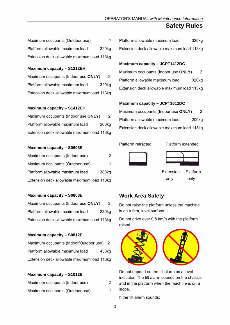
Platform retracted Platform extended
Extension Platform
only only
Work Area Safety
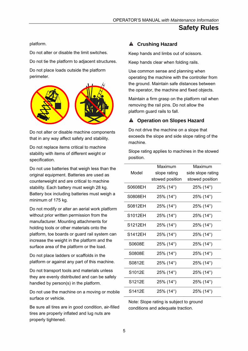
Do not raise the platform unless the machine
is on a firm, level surface.
Do not drive over 0.8 km/h with the platform
raised.
Do not depend on the tilt alarm as a level
indicator. The tilt alarm sounds on the chassis
and in the platform when the machine is on a
slope.
If the tilt alarm sounds:

OPERATOR’S MANUAL with Maintenance Information
Safety Rules
4
Lower the platform. Move the machine to a
firm, level surface. If the tilt alarm sounds
when the platform is raised, use extreme
caution to lower the platform.
For outdoor use machine, do not raise the
platform when wind speeds may exceed 12.5
m/s. If wind speeds exceed 12.5 m/s when the
platform is raised, lower the platform and do
not continue to operate the machine.
Do not operate the machine in strong or gusty
winds. Do not increase the surface area of the
platform or the load. Increasing the area
exposed to the wind will decrease machine
stability.
Do not use the platform controls to free a
platform that is caught, snagged or otherwise
prevented from normal motion by an adjacent
structure. All personnel must be removed from
the platform before attempting to free the
platform using the ground controls.
Use extreme care and slow speeds while
driving the machine in the stowed position
across uneven terrain, debris, unstable or
slippery surfaces and near holes and
drop-offs.
Do not drive the machine on or near uneven
terrain, unstable surfaces or other hazardous
conditions with the platform raised.
Do not push off or pull toward any object
outside of the platform.
Maximum allowable manual force
Model Application manual
force
Maximum
occupants
S0608EH Outdoor 200N 1
Indoor 400N 2
S0808EH Indoor 400N 2
S0812EH Outdoor 400N 2
Indoor 400N 2
S1012EH Outdoor 200N 1
Indoor 400N 2
S1212EH Indoor 400N 2
S1412EH Indoor 400N 2
S0608E Outdoor 200N 1
Indoor 400N 2
S0808E Indoor 400N 2
S0812E Outdoor 400N 2
Indoor 400N 2
S1012E Outdoor 200N 1
Indoor 400N 2
S1212E Indoor 400N 2
S1412E Indoor 400N 2
Do not use the machine as a crane.
Do not place or attach fixed or overhanging
loads to any part of this machine.
Do not push the machine or other objects with
the platform.
Do not operate the machine with the chassis
trays open.
Do not contact adjacent structures with the
OPERATOR’S MANUAL with Maintenance Information
Safety Rules
5
platform.
Do not alter or disable the limit switches.
Do not tie the platform to adjacent structures.
Do not place loads outside the platform
perimeter.
Do not alter or disable machine components
that in any way affect safety and stability.
Do not replace items critical to machine
stability with items of different weight or
specification.
Do not use batteries that weigh less than the
original equipment. Batteries are used as
counterweight and are critical to machine
stability. Each battery must weigh 28 kg.
Battery box including batteries must weigh a
minimum of 175 kg.
Do not modify or alter an aerial work platform
without prior written permission from the
manufacturer. Mounting attachments for
holding tools or other materials onto the
platform, toe boards or guard rail system can
increase the weight in the platform and the
surface area of the platform or the load.
Do not place ladders or scaffolds in the
platform or against any part of this machine.
Do not transport tools and materials unless
they are evenly distributed and can be safely
handled by person(s) in the platform.
Do not use the machine on a moving or mobile
surface or vehicle.
Be sure all tires are in good condition, air-filled
tires are properly inflated and lug nuts are
properly tightened.
Crushing Hazard
Keep hands and limbs out of scissors.
Keep hands clear when folding rails.
Use common sense and planning when
operating the machine with the controller from
the ground. Maintain safe distances between
the operator, the machine and fixed objects.
Maintain a firm grasp on the platform rail when
removing the rail pins. Do not allow the
platform guard rails to fall.
Operation on Slopes Hazard
Do not drive the machine on a slope that
exceeds the slope and side slope rating of the
machine.
Slope rating applies to machines in the stowed
position.
Model
Maximum
slope rating
stowed position
Maximum
side slope rating
stowed position
S0608EH 25% (14°) 25% (14°)
S0808EH 25% (14°) 25% (14°)
S0812EH 25% (14°) 25% (14°)
S1012EH 25% (14°) 25% (14°)
S1212EH 25% (14°) 25% (14°)
S1412EH 25% (14°) 25% (14°)
S0608E 25% (14°) 25% (14°)
S0808E 25% (14°) 25% (14°)
S0812E 25% (14°) 25% (14°)
S1012E 25% (14°) 25% (14°)
S1212E 25% (14°) 25% (14°)
S1412E 25% (14°) 25% (14°)
Note: Slope rating is subject to ground
conditions and adequate traction.
OPERATOR’S MANUAL with Maintenance Information
Safety Rules
6
Fall Hazard
The guard rail system provides fall protection.
During operation, occupants in the platform
must wear a full body harness with a lanyard
attached to an authorized lanyard anchorage
point. Attach only one (1) lanyard per lanyard
anchorage point.
Do not sit, stand or climb on the platform guard
rails. Maintain a firm footing on the platform
floor at all times.
Do not climb down from the platform when
raised.
Keep the platform floor clear of debris.
Close the entry gate before operating.
Do not operate the machine unless the guard
rails are properly installed and the entry is
secured for operation.
Do not enter or exit the platform unless the
machine is in the stowed position.
Collision Hazard
Be aware of limited sight distance and blind
spots when driving or operating.
Be aware of extended platform position(s)
when moving the machine.
Check the work area for overhead obstructions
or other possible hazards.
Be aware of crushing hazards when grasping
the platform guard rail.
Operators must comply with employer, job site
and governmental rules regarding use of
personal protective equipment.
Observe and use color-coded direction arrows
on the platform controls and platform decal
plate for drive and steer functions.
Do not operate a machine in the path of any
crane or moving overhead machinery unless
the controls of the crane have been locked out
and/or precautions have been taken to prevent
any potential collision.
No stunt driving or horseplay while operating a
machine.
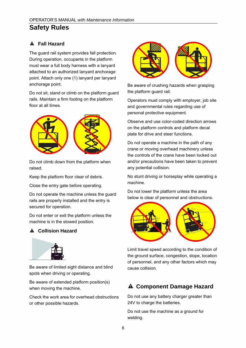
Do not lower the platform unless the area
below is clear of personnel and obstructions.
Limit travel speed according to the condition of
the ground surface, congestion, slope, location
of personnel, and any other factors which may
cause collision.
Component Damage Hazard
Do not use any battery charger greater than
24V to charge the batteries.
Do not use the machine as a ground for
welding.

OPERATOR’S MANUAL with Maintenance Information
Safety Rules
7
Explosion and Fire Hazard
Do not operate the machine or charge the
batteries in hazardous locations where
potentially flammable or explosive gases or
particles may be present.
Damaged Machine Hazard
Do not use a damaged or malfunctioning
machine.
Conduct a thorough pre-operation inspection
of the machine and test all functions before
each work shift. Immediately tag and remove
from service a damaged or malfunctioning
machine.
Be sure all maintenance has been performed
as specified in this manual. Be sure all decals
are in place and legible.
Be sure the operator’s manual is complete,
legible and in the storage container located in
the platform.
Bodily Injury Hazard
Do not operate the machine with a hydraulic oil
or air leak. An air leak or hydraulic leak can
penetrate and/or burn skin.
Improper contact with components under any
cover will cause serious injury. Only trained
maintenance personnel should access
compartments. Access by the operator is only
advised when performing a pre-operation
inspection. All compartments must remain
closed and secured during operation.
Battery Safety
Burn Hazard
Batteries contain acid. Always wear protective
clothing and eye wear when working with
batteries.
Avoid spilling or contacting battery acid.
Neutralize battery acid spills with baking soda
and water.
Explosion Hazard
Keep sparks, flames and lighted tobacco away
from batteries. Batteries emit explosive gas.
The battery tray should remain open during the
entire charging cycle.
Do not contact the battery terminals or the
cable clamps with tools that may cause
sparks.
Component Damage Hazard
Do not use any battery charger greater than
24V to charge the batteries.
Electrocution/ Burn Hazard
Connect the battery charger
to a grounded, AC 3-wire
electrical outlet only.
Inspect daily for damaged
cords, cables and wires.
Replace damaged items
before operating.
Avoid electrical shock from contact with
battery terminals. Remove all rings, watches
and other jewelry.

OPERATOR’S MANUAL with Maintenance Information
Safety Rules
8
Tip-over Hazard
Do not use batteries that weigh less than the
original equipment. Batteries are used as
counterweight and are critical to machine
stability. Each battery must weigh 28 kg.
Battery tray including batteries must weigh a
minimum of 175 kg.
Lifting Hazard
Use the appropriate number of people and
proper lifting techniques when lifting batteries.
Lockout after Each Use
1 Select a safe parking location - firm level
surface, clear of obstruction and traffic.
2 Lower the platform.
3 Turn the key switch to the off position and
remove the key to secure from
unauthorized use.
4 Chock the wheels.
5 Charge the batteries.
OPERATOR’S MANUAL with Maintenance Information
Legend
9
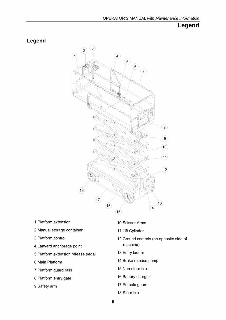
Legend
1 Platform extension
2 Manual storage container
3 Platform control
4 Lanyard anchorage point
5 Platform extension release pedal
6 Main Platform
7 Platform guard rails
8 Platform entry gate
9 Safety arm
10 Scissor Arms
11 Lift Cylinder
12 Ground controls (on opposite side of
machine)
13 Entry ladder
14 Brake release pump
15 Non-steer tire
16 Battery charger
17 Pothole guard
18 Steer tire
6
2
9
11
15
1316
10
1
18
7
3
12
5
8
17
14
4
OPERATOR’S MANUAL with Maintenance Information
Decals
10
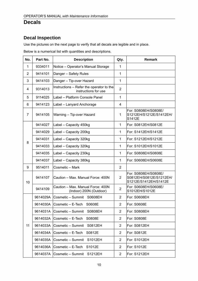
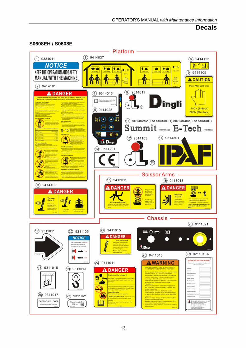
Decal Inspection Use the pictures on the next page to verify that all decals are legible and in place.
Below is a numerical list with quantities and descriptions.
No. Part No. Description Qty. Remark
1 9334011 Notice – Operator’s Manual Storage 1
2 9414101 Danger – Safety Rules 1
3 9414103 Danger – Tip-over Hazard 1
4 9314013 Instructions – Refer the operator to the
instructions for use 2
5 9114025 Label – Platform Console Panel 1
6 9414123 Label – Lanyard Anchorage 4
7 9414105 Warning – Tip-over Hazard 1 For: S0808EH/S0808E/ S1212EH/S1212E/S1412EH/S1412E
8
9414027 Label – Capacity 450kg 1 For: S0812EH/S0812E
9414029 Label – Capacity 200kg 1 For: S1412EH/S1412E
9414031 Label – Capacity 320kg 1 For: S1212EH/S1212E
9414033 Label – Capacity 320kg 1 For: S1012EH/S1012E
9414035 Label – Capacity 230kg 1 For: S0808EH/S0808E
9414037 Label – Capacity 380kg 1 For: S0608EH/S0608E
9 9514011 Cosmetic – Mark 2
10 9414107 Caution – Max. Manual Force: 400N 2
For: S0808EH/S0808E/ S0812EH/S0812E/S1212EH/S1212E/S1412EH/S1412E
9414109 Caution – Max. Manual Force: 400N
(Indoor) 200N (Outdoor) 2
For: S0608EH/S0608E/ S1012EH/S1012E
11
9614029A Cosmetic – Summit S0608EH 2 For: S0608EH
9614030A Cosmetic – E-Tech S0608E 2 For: S0608E
9614031A Cosmetic – Summit S0808EH 2 For: S0808EH
9614032A Cosmetic – E-Tech S0808E 2 For: S0808E
9614033A Cosmetic – Summit S0812EH 2 For: S0812EH
9614034A Cosmetic – E-Tech S0812E 2 For: S0812E
9614035A Cosmetic – Summit S1012EH 2 For: S1012EH
9614036A Cosmetic – E-Tech S1012E 2 For: S1012E
9614037A Cosmetic – Summit S1212EH 2 For: S1212EH

OPERATOR’S MANUAL with Maintenance Information
Decals
11
No. Part No. Description Qty. Remark
11
9614038A Cosmetic – E-Tech S1212E 2 For: S1212E
9614039A Cosmetic – Summit S1412EH 2 For: S1412EH
9614040A Cosmetic – E-Tech S1412E 2 For: S1412E
12
9514101 Cosmetic – Mark 1 For: S0608EH/S0608E/ S0808EH/S0808E/S1412EH/S1412E
9514103 Cosmetic – Mark 1 For: S0812EH/S0812E/ S1012EH/S1012E/S1212EH/S1212E
13 9514201 Cosmetic – CE 3
14 9514301 Cosmetic – IPAF 1
15 9413011 Danger – Safety Arm 2
For: S0608EH/S0608E/ S0808EH/S0808E/S0812EH/S0812E/S1012EH/S1012E
4 For: S1212EH/S1212E/ S1412EH/S1412E
16 9413013 Danger – Crushing Hazard 3
For: S0608EH/S0608E/ S0808EH/S0808E/S0812EH/S0812E/S1012EH/S1012E
5 For: S1212EH/S1212E/ S1412EH/S1412E
17 9311011 Instructions – Forklift Pockets 2
18 9311015 Instructions – Tie Down Point 4
19 9311013 Instructions – Lift Point 4
20 9311017 Instructions – Emergency Lower 1
21
9311021 Instructions – Wheel Load: 830kg 4 For: S0608EH/S0608E/ S0808EH/S0808E
9311023 Instructions – Wheel Load: 1160kg 4 For: S1212EH/S1212E/ S1412EH/S1412E
9311025 Instructions – Wheel Load: 1050kg 4 For:S0812EH/S0812E/ S1012EH/S1012E
22 9311105 Notice – Main Power Switch Operation 1
23 9411011 Danger – Explosion / Burn Hazard 1
24 9411015 Danger – Tip-over Hazard 1
25 9111021 Label – Ground Console Panel 1
26 9411013 Warning – Inspected and Operation
Properly 1
27 9211013A Decal – Manufacturer’s Plate 1

OPERATOR’S MANUAL with Maintenance Information
Decals
12
1 2 3
6
7
8
9
10
11
12
15
16
17
1918
1721
20
23
21
24
25
19
16
21
21
1819
2718
13
14
26
15
16
13
13
1819
22
45
9
10
11
4
OPERATOR’S MANUAL with Maintenance Information
Decals
13
S0608EH / S0608E

OPERATOR’S MANUAL with Maintenance Information
Decals
14
S0808EH / S0808E

OPERATOR’S MANUAL with Maintenance Information
Decals
15
S0812EH / S0812E

OPERATOR’S MANUAL with Maintenance Information
Decals
16
S1012EH / S1012E

OPERATOR’S MANUAL with Maintenance Information
Decals
17
S1212EH/S1212E

OPERATOR’S MANUAL with Maintenance Information
Decals
18
S1412EH/S1412

OPERATOR’S MANUAL with Maintenance Information
Specifications
19
Model: S0608EH
Height, working maximum 8 m
Height, platform maximum 6 m
Height, stowed maximum Rails up
2.21 m
Height, stowed maximum Rails lowered
1.75 m
Width 0.81 m
Length, platform retracted 2.48 m
Length, platform extended 3.38 m
Platform dimensions Platform length x width
2.27 x 0.81 m
Platform extension length 0.9 m
Maximum load capacity 380 kg
Maximum wind speed 12.5 m/s
Wheelbase 1.87 m
Turning radius (outside) 2.10 m
Turning radius (inside) 0
Ground clearance 10 cm
Ground clearance Pothole guards deployed
1.9 cm
Weight (1840 kg)
Machine weights vary with option configurations
Power source 4 Batteries , 6V 225AH
Controls Proportional
AC outlet in platform Standard
Maximum hydraulic pressure (functions)
240 bar
System voltage 24 V
Tire size Φ381×127
Airborne noise emissions <70 dB
Maximum sound level at normal operating workstations (A-weighted)
Vibration value does not exceed 2.5m/s2
Maximum slope rating, Stowed position
25%
Maximum side slope rating, Stowed position
25%
Note: Slope rating is subject to ground conditions and adequate traction.
Maximum working slope X-2°,Y-3°
Drive speeds
Stowed, maximum 3.5 km/h
Platform raised, maximum 0.8 km/h
Floor loading information
Tire load, maximum 830 kg
Tire contact pressure 8.17 Kg/cm2
800.6 kPa
Occupied floor pressure 1105 Kg/m2
10.8 kPa
Note: Floor loading information is approximate
and does not incorporate different option
configurations.
It should be used only with adequate safety
factors.
Continuous improvement of our products is a
DINGLI policy. Product specifications are
subject to change without notice or obligation.

OPERATOR’S MANUAL with Maintenance Information
Specifications
20
Model: S0808EH
Height, working maximum 10 m
Height, platform maximum 8 m
Height, stowed maximum Rails up
2.34 m
Height, stowed maximum Rails lowered
1.88 m
Width 0.81 m
Length, platform retracted 2.48 m
Length, platform extended 3.38 m
Platform dimensions Platform length x width
2.27 x 0.81 m
Platform extension length 0.9 m
Maximum load capacity 230 kg
Maximum wind speed 0 m/s
Wheelbase 1.87 m
Turning radius (outside) 2.10 m
Turning radius (inside) 0
Ground clearance 10 cm
Ground clearance Pothole guards deployed
1.9 cm
Weight (2020 kg)
Machine weights vary with option configurations
Power source 4 Batteries , 6V 225AH
Controls Proportional
AC outlet in platform Standard
Maximum hydraulic pressure (functions)
240 bar
System voltage 24 V
Tire size Φ381×127
Airborne noise emissions <70 dB
Maximum sound level at normal operating workstations (A-weighted)
Vibration value does not exceed 2.5m/s2
Maximum slope rating, Stowed position
25%
Maximum side slope rating, Stowed position
25%
Note: Slope rating is subject to ground conditions and adequate traction.
Maximum working slope X-1.5°,Y-3°
Drive speeds
Stowed, maximum 3.5 km/h
Platform raised, maximum 0.8 km/h
Floor loading information
Tire load, maximum 830 kg
Tire contact pressure 8.17 Kg/cm2
800.6 kPa
Occupied floor pressure 1120 Kg/m2
11 kPa
Note: Floor loading information is approximate
and does not incorporate different option
configurations.
It should be used only with adequate safety
factors.
Continuous improvement of our products is a
DINGLI policy. Product specifications are
subject to change without notice or obligation.

OPERATOR’S MANUAL with Maintenance Information
Specifications
21
Model: S0812EH
Height, working maximum 10 m
Height, platform maximum 8 m
Height, stowed maximum Rails up
2.34 m
Height, stowed maximum Rails lowered
1.86 m
Width 1.15 m
Length, platform retracted 2.48 m
Length, platform extended 3.38 m
Platform dimensions Platform length x width
2.27 x 1.12 m
Platform extension length 0.9 m
Maximum load capacity 450 kg
Maximum wind speed 12.5 m/s
Wheelbase 1.87 m
Turning radius (outside) 2.33 m
Turning radius (inside) 0
Ground clearance 10 cm
Ground clearance Pothole guards deployed
1.9 cm
Weight (2180 kg)
Machine weights vary with option configurations
Power source 4 Batteries , 6V 225AH
Controls Proportional
AC outlet in platform Standard
Maximum hydraulic pressure (functions)
240 bar
System voltage 24 V
Tire size Φ381×127
Airborne noise emissions <70 dB
Maximum sound level at normal operating workstations (A-weighted)
Vibration value does not exceed 2.5m/s2
Maximum slope rating, Stowed position
25%
Maximum side slope rating, Stowed position
25%
Note: Slope rating is subject to ground conditions and adequate traction.
Maximum working slope X-2°, Y-3°
Drive speeds
Stowed, maximum 3.5 km/h
Platform raised, maximum 0.8 km/h
Floor loading information
Tire load, maximum 1050 kg
Tire contact pressure 10.3 Kg/cm2
1012.8 kPa
Occupied floor pressure 922 Kg/m2
9.04 kPa
Note: Floor loading information is approximate
and does not incorporate different option
configurations.
It should be used only with adequate safety
factors.
Continuous improvement of our products is a
DINGLI policy. Product specifications are
subject to change without notice or obligation.

OPERATOR’S MANUAL with Maintenance Information
Specifications
22
Model: S1012EH
Height, working maximum 12 m
Height, platform maximum 10 m
Height, stowed maximum Rails up
2.47 m
Height, stowed maximum Rails lowered
1.99 m
Width 1.15 m
Length, platform retracted 2.47 m
Length, platform extended 3.38 m
Platform dimensions Platform length x width
2.27 x 1.12 m
Platform extension length 0.9 m
Maximum load capacity 320 kg
Maximum wind speed 12.5 m/s
Wheelbase 1.87 m
Turning radius (outside) 2.20 m
Turning radius (inside) 0
Ground clearance 10 cm
Ground clearance Pothole guards deployed
1.9 cm
Weight (2430 kg)
Machine weights vary with option configurations
Power source 4 Batteries , 6V 225AH
Controls Proportional
AC outlet in platform Standard
Maximum hydraulic pressure (functions)
240bar
System voltage 24V
Tire size Φ381×127
Airborne noise emissions <70 dB
Maximum sound level at normal operating workstations (A-weighted)
Vibration value does not exceed 2.5m/s2
Maximum slope rating, Stowed position
25%
Maximum side slope rating, Stowed position
25%
Note: Slope rating is subject to ground conditions and adequate traction.
Maximum working slope X-2°,Y-3°
Drive speeds
Stowed, maximum 3.5 km/h
Platform raised, maximum 0.8 km/h
Floor loading information
Tire load, maximum 1050 kg
Tire contact pressure 10.3 Kg/cm2
1012.8 kPa
Occupied floor pressure 964 Kg/m2
9.45 kPa
Note: Floor loading information is approximate
and does not incorporate different option
configurations.
It should be used only with adequate safety
factors.
Continuous improvement of our products is a
DINGLI policy. Product specifications are
subject to change without notice or obligation.

OPERATOR’S MANUAL with Maintenance Information
Specifications
23
Model: S1212EH
Height, working maximum 14 m
Height, platform maximum 12 m
Height, stowed maximum Rails up
2.59 m
Height, stowed maximum Rails lowered
2.17 m
Width 1.15 m
Length, platform retracted 2.48 m
Length, platform extended 3.38 m
Platform dimensions Platform length x width
2.27 x 1.12 m
Platform extension length 0.9 m
Maximum load capacity 320 kg
Maximum wind speed 0 m/s
Wheelbase 1.87 m
Turning radius (outside) 2.20 m
Turning radius (inside) 0
Ground clearance 10cm
Ground clearance Pothole guards deployed
1.9 cm
Weight (2860kg)
Machine weights vary with option configurations
Power source 4 Batteries , 6V 240AH
Controls Proportional
AC outlet in platform Standard
Maximum hydraulic pressure (functions)
240 bar
System voltage 24V
Tire size Φ381×127
Airborne noise emissions <70 dB
Maximum sound level at normal operating workstations (A-weighted)
Vibration value does not exceed 2.5m/s2
Maximum slope rating, Stowed position
25%
Maximum side slope rating, Stowed position
25%
Note: Slope rating is subject to ground conditions and adequate traction.
Maximum working slope X-1.5°,Y-3°
Drive speeds
Stowed, maximum 3.5 km/h
Platform raised, maximum 0.8 km/h
Floor loading information
Tire load, maximum 1160 kg
Tire contact pressure 11.4Kg/cm2
118.9.8kPa
Occupied floor pressure 1115Kg/m2
10.9kPa
Note: Floor loading information is approximate
and does not incorporate different option
configurations.
It should be used only with adequate safety
factors.
Continuous improvement of our products is a
DINGLI policy. Product specifications are
subject to change without notice or obligation.

OPERATOR’S MANUAL with Maintenance Information
Specifications
24
Model: S1412EH
Height, working maximum 15.7 m
Height, platform maximum 13.7 m
Height, stowed maximum Rails up
2.59 m
Height, stowed maximum Rails lowered
2.17 m
Width 1.25 m
Length, platform retracted 2.84 m
Length, platform extended 3.74 m
Platform dimensions Platform length x width
2.64 x 0.81 m
Platform extension length 0.9 m
Maximum load capacity 200 kg
Maximum wind speed 0 m/s
Wheelbase 2.22 m
Turning radius (outside) 2.65 m
Turning radius (inside) 0
Ground clearance 10cm
Ground clearance Pothole guards deployed
1.9 cm
Weight (3050kg)
Machine weights vary with option configurations
Power source 4 Batteries , 6V 240AH
Controls Proportional
AC outlet in platform Standard
Maximum hydraulic pressure (functions)
240 bar
System voltage 24V
Tire size Φ381×127
Airborne noise emissions <70 dB
Maximum sound level at normal operating workstations (A-weighted)
Vibration value does not exceed 2.5m/s2
Maximum slope rating, Stowed position
25%
Maximum side slope rating, Stowed position
25%
Note: Slope rating is subject to ground conditions and adequate traction.
Maximum working slope X-1.5°,Y-3°
Drive speeds
Stowed, maximum 3.5 km/h
Platform raised, maximum 0.8 km/h
Floor loading information
Tire load, maximum 1160 kg
Tire contact pressure 11.4Kg/cm2
1118.9kPa
Occupied floor pressure 915.5Kg/m2
8.97kPa
Note: Floor loading information is approximate
and does not incorporate different option
configurations.
It should be used only with adequate safety
factors.
Continuous improvement of our products is a
DINGLI policy. Product specifications are
subject to change without notice or obligation.

OPERATOR’S MANUAL with Maintenance Information
Specifications
25
Model: S0608E
Height, working maximum 8 m
Height, platform maximum 6 m
Height, stowed maximum Rails up
2.21 m
Height, stowed maximum Rails lowered
1.75 m
Width 0.81 m
Length, platform retracted 2.48 m
Length, platform extended 3.38 m
Platform dimensions Platform length x width
2.27 x 0.81 m
Platform extension length 0.9 m
Maximum load capacity 380 kg
Maximum wind speed 12.5 m/s
Wheelbase 1.87 m
Turning radius (outside) 2.10 m
Turning radius (inside) 0
Ground clearance 10 cm
Ground clearance Pothole guards deployed
1.9 cm
Weight (1900 kg)
Machine weights vary with option configurations
Power source 4 Batteries , 6V 225AH
Controls Proportional
AC outlet in platform Standard
Maximum hydraulic pressure (functions)
240 bar
System voltage 24 V
Tire size Φ381×127
Airborne noise emissions <70 dB
Maximum sound level at normal operating workstations (A-weighted)
Vibration value does not exceed 2.5m/s2
Maximum slope rating, Stowed position
25%
Maximum side slope rating, Stowed position
25%
Note: Slope rating is subject to ground conditions and adequate traction.
Maximum working slope X-2°,Y-3°
Drive speeds
Stowed, maximum 4.5km/h
Platform raised, maximum 0.8 km/h
Floor loading information
Tire load, maximum 830 kg
Tire contact pressure 8.17 Kg/cm2
800.6 kPa
Occupied floor pressure 1135 Kg/m2
11.1 kPa
Note: Floor loading information is approximate
and does not incorporate different option
configurations.
It should be used only with adequate safety
factors.
Continuous improvement of our products is a
DINGLI policy. Product specifications are
subject to change without notice or obligation.

OPERATOR’S MANUAL with Maintenance Information
Specifications
26
Model: S0808E
Height, working maximum 10 m
Height, platform maximum 8 m
Height, stowed maximum Rails up
2.34 m
Height, stowed maximum Rails lowered
1.88 m
Width 0.81 m
Length, platform retracted 2.48 m
Length, platform extended 3.38 m
Platform dimensions Platform length x width
2.27 x 0.81 m
Platform extension length 0.9 m
Maximum load capacity 230 kg
Maximum wind speed 0 m/s
Wheelbase 1.87 m
Turning radius (outside) 2.10 m
Turning radius (inside) 0
Ground clearance 10 cm
Ground clearance Pothole guards deployed
1.9 cm
Weight (2080 kg)
Machine weights vary with option configurations
Power source 4 Batteries , 6V 225AH
Controls Proportional
AC outlet in platform Standard
Maximum hydraulic pressure (functions)
240 bar
System voltage 24 V
Tire size Φ381×127
Airborne noise emissions <70 dB
Maximum sound level at normal operating workstations (A-weighted)
Vibration value does not exceed 2.5m/s2
Maximum slope rating, Stowed position
25%
Maximum side slope rating, Stowed position
25%
Note: Slope rating is subject to ground conditions and adequate traction.
Maximum working slope X-1.5°,Y-3°
Drive speeds
Stowed, maximum 4.5 km/h
Platform raised, maximum 0.8 km/h
Floor loading information
Tire load, maximum 830 kg
Tire contact pressure 8.17 Kg/cm2
800.6 kPa
Occupied floor pressure 1150 Kg/m2
11.2 kPa
Note: Floor loading information is approximate
and does not incorporate different option
configurations.
It should be used only with adequate safety
factors.
Continuous improvement of our products is a
DINGLI policy. Product specifications are
subject to change without notice or obligation.
OPERATOR’S MANUAL with Maintenance Information
Specifications
27
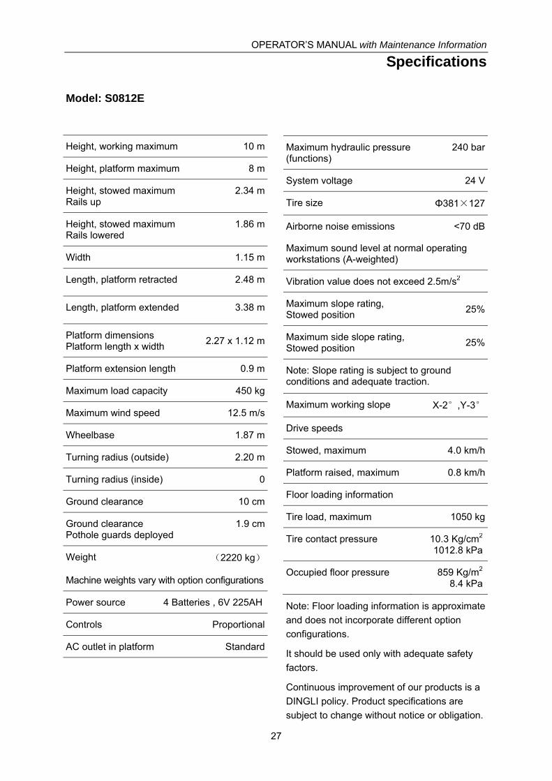
Model: S0812E
Height, working maximum 10 m
Height, platform maximum 8 m
Height, stowed maximum Rails up
2.34 m
Height, stowed maximum Rails lowered
1.86 m
Width 1.15 m
Length, platform retracted 2.48 m
Length, platform extended 3.38 m
Platform dimensions Platform length x width
2.27 x 1.12 m
Platform extension length 0.9 m
Maximum load capacity 450 kg
Maximum wind speed 12.5 m/s
Wheelbase 1.87 m
Turning radius (outside) 2.20 m
Turning radius (inside) 0
Ground clearance 10 cm
Ground clearance Pothole guards deployed
1.9 cm
Weight (2220 kg)
Machine weights vary with option configurations
Power source 4 Batteries , 6V 225AH
Controls Proportional
AC outlet in platform Standard
Maximum hydraulic pressure (functions)
240 bar
System voltage 24 V
Tire size Φ381×127
Airborne noise emissions <70 dB
Maximum sound level at normal operating workstations (A-weighted)
Vibration value does not exceed 2.5m/s2
Maximum slope rating, Stowed position
25%
Maximum side slope rating, Stowed position
25%
Note: Slope rating is subject to ground conditions and adequate traction.
Maximum working slope X-2°,Y-3°
Drive speeds
Stowed, maximum 4.0 km/h
Platform raised, maximum 0.8 km/h
Floor loading information
Tire load, maximum 1050 kg
Tire contact pressure 10.3 Kg/cm2
1012.8 kPa
Occupied floor pressure 859 Kg/m2
8.4 kPa
Note: Floor loading information is approximate
and does not incorporate different option
configurations.
It should be used only with adequate safety
factors.
Continuous improvement of our products is a
DINGLI policy. Product specifications are
subject to change without notice or obligation.

OPERATOR’S MANUAL with Maintenance Information
Specifications
28
Model: S1012E
Height, working maximum 12 m
Height, platform maximum 10 m
Height, stowed maximum Rails up
2.47 m
Height, stowed maximum Rails lowered
1.99 m
Width 1.15 m
Length, platform retracted 2.48 m
Length, platform extended 3.38 m
Platform dimensions Platform length x width
2.27 x 1.12 m
Platform extension length 0.9 m
Maximum load capacity 320 kg
Maximum wind speed 12.5 m/s
Wheelbase 1.87 m
Turning radius (outside) 2.20 m
Turning radius (inside) 0
Ground clearance 10 cm
Ground clearance Pothole guards deployed
1.9 cm
Weight (2490 kg)
Machine weights vary with option configurations
Power source 4 Batteries , 6V 225AH
Controls Proportional
AC outlet in platform Standard
Maximum hydraulic pressure (functions)
240 bar
System voltage 24 V
Tire size Φ381×127
Airborne noise emissions <70 dB
Maximum sound level at normal operating workstations (A-weighted)
Vibration value does not exceed 2.5m/s2
Maximum slope rating, Stowed position
25%
Maximum side slope rating, Stowed position
25%
Note: Slope rating is subject to ground conditions and adequate traction.
Maximum working slope X-2°,Y-3°
Drive speeds
Stowed, maximum 4.0 km/h
Platform raised, maximum 0.8 km/h
Floor loading information
Tire load, maximum 1050 kg
Tire contact pressure 10.3 Kg/cm2
1012.8 kPa
Occupied floor pressure 985 Kg/m2
9.6 kPa
Note: Floor loading information is approximate
and does not incorporate different option
configurations.
It should be used only with adequate safety
factors.
Continuous improvement of our products is a
DINGLI policy. Product specifications are
subject to change without notice or obligation.
OPERATOR’S MANUAL with Maintenance Information
Specifications
29
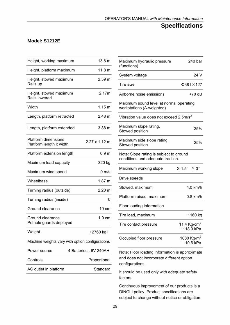
Model: S1212E
Height, working maximum 13.8 m
Height, platform maximum 11.8 m
Height, stowed maximum Rails up
2.59 m
Height, stowed maximum Rails lowered
2.17m
Width 1.15 m
Length, platform retracted 2.48 m
Length, platform extended 3.38 m
Platform dimensions Platform length x width
2.27 x 1.12 m
Platform extension length 0.9 m
Maximum load capacity 320 kg
Maximum wind speed 0 m/s
Wheelbase 1.87 m
Turning radius (outside) 2.20 m
Turning radius (inside) 0
Ground clearance 10 cm
Ground clearance Pothole guards deployed
1.9 cm
Weight (2760 kg)
Machine weights vary with option configurations
Power source 4 Batteries , 6V 240AH
Controls Proportional
AC outlet in platform Standard
Maximum hydraulic pressure (functions)
240 bar
System voltage 24 V
Tire size Φ381×127
Airborne noise emissions <70 dB
Maximum sound level at normal operating workstations (A-weighted)
Vibration value does not exceed 2.5m/s2
Maximum slope rating, Stowed position
25%
Maximum side slope rating, Stowed position
25%
Note: Slope rating is subject to ground conditions and adequate traction.
Maximum working slope X-1.5°,Y-3°
Drive speeds
Stowed, maximum 4.0 km/h
Platform raised, maximum 0.8 km/h
Floor loading information
Tire load, maximum 1160 kg
Tire contact pressure 11.4 Kg/cm2
1118.9 kPa
Occupied floor pressure 1080 Kg/m2
10.6 kPa
Note: Floor loading information is approximate
and does not incorporate different option
configurations.
It should be used only with adequate safety
factors.
Continuous improvement of our products is a
DINGLI policy. Product specifications are
subject to change without notice or obligation.
OPERATOR’S MANUAL with Maintenance Information
Specifications
30
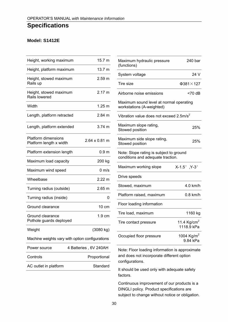
Model: S1412E
Height, working maximum 15.7 m
Height, platform maximum 13.7 m
Height, stowed maximum Rails up
2.59 m
Height, stowed maximum Rails lowered
2.17 m
Width 1.25 m
Length, platform retracted 2.84 m
Length, platform extended 3.74 m
Platform dimensions Platform length x width
2.64 x 0.81 m
Platform extension length 0.9 m
Maximum load capacity 200 kg
Maximum wind speed 0 m/s
Wheelbase 2.22 m
Turning radius (outside) 2.65 m
Turning radius (inside) 0
Ground clearance 10 cm
Ground clearance Pothole guards deployed
1.9 cm
Weight (3080 kg)
Machine weights vary with option configurations
Power source 4 Batteries , 6V 240AH
Controls Proportional
AC outlet in platform Standard
Maximum hydraulic pressure (functions)
240 bar
System voltage 24 V
Tire size Φ381×127
Airborne noise emissions <70 dB
Maximum sound level at normal operating workstations (A-weighted)
Vibration value does not exceed 2.5m/s2
Maximum slope rating, Stowed position
25%
Maximum side slope rating, Stowed position
25%
Note: Slope rating is subject to ground conditions and adequate traction.
Maximum working slope X-1.5°,Y-3°
Drive speeds
Stowed, maximum 4.0 km/h
Platform raised, maximum 0.8 km/h
Floor loading information
Tire load, maximum 1160 kg
Tire contact pressure 11.4 Kg/cm2
1118.9 kPa
Occupied floor pressure 1004 Kg/m2
9.84 kPa
Note: Floor loading information is approximate
and does not incorporate different option
configurations.
It should be used only with adequate safety
factors.
Continuous improvement of our products is a
DINGLI policy. Product specifications are
subject to change without notice or obligation.

OPERATOR’S MANUAL with Maintenance Information
Control Panel
31
Ground Control Panel
1 Key switch for platform / off / ground control
selection
Turn the key switch to the platform position
and the platform controls will operate. Turn
the key switch to the off position and the
machine will be off. Turn the key switch to
the base position and the ground controls will
operate.
2 Platform up / down switch
Move the switch up and the platform will
raise. Move the switch down and the platform
will lower.
3 7 amp breaker for electric circuits
4 Indicator light
5 Red Emergency Stop button
Push in the red Emergency Stop button
to the off position to stop all functions.
Pull out the red Emergency Stop button
to the on position to operate the machine.
○1 ○2 ○3 ○4 ○5
OPERATOR’S MANUAL with Maintenance Information
Control Panel
32
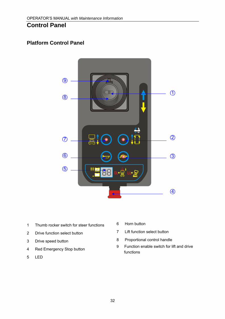
Platform Control Panel
1 Thumb rocker switch for steer functions
2 Drive function select button
3 Drive speed button
4 Red Emergency Stop button
5 LED
6 Horn button
7 Lift function select button
8 Proportional control handle
9 Function enable switch for lift and drive
functions
○1
○2
○3
○4
○9
○8
○7
○6
○5

OPERATOR’S MANUAL with Maintenance Information
Control Panel
33
Platform Control Panel
1 Thumb rocker switch for steer functions
Press the thumb rocker switch in either
direction to activate steer
2 Drive function select button
Press this button to activate the drive
function.
3 Drive speed button
Press this button to activate the slow or
fast drive function.
4 Red Emergency Stop button
Push in the red Emergency Stop button to
the off position to stop all functions. Pull
out the red Emergency Stop button to the
on position to operate the machine.
5 LED
Diagnostic readout and battery charge
indicator.
6 Horn Button
Push the horn button and the horn will
sound. Release the horn button and the
horn will stop.
7 Lift function select button
Press this button to activate the lift
function.
8 Proportional control handle
9 Function enable switch for lift and drive
functions
Lift function: Press and hold the function
enable switch to enable the lift function on
the platform control handle. Move the
control handle in the direction indicated by
the blue arrow and the platform will raise.
Move the control handle in the direction
indicated by the yellow arrow and the
platform will lower. The descent alarm
should sound while the platform is
lowering.
Drive function: Press and hold the
function enable switch to enable the drive
function on the platform control handle.
Move the control handle in the direction
indicated by the blue arrow on the control
panel and the machine will move in the
direction that the blue arrow points. Move
the control handle in the direction
indicated by the yellow arrow on the
control panel and the machine will move
in the direction that the yellow arrow
points.
OPERATOR’S MANUAL with Maintenance Information
Pre-operation Inspection
34
Do Not Operate Unless:
√ You learn and practice the principles of
safe machine operation contained in this
operator's manual.
1 Avoid hazardous situations.
2 Always perform a pre-operation
inspection.
Know and understand the pre-operation
inspection before going on to the next
section.
3 Inspect the workplace.
4 Always perform function tests prior to
use.
5 Only use the machine as it was
intended.
Fundamentals
It is the responsibility of the operator to
perform a pre-operation inspection and routine
maintenance.
The pre-operation inspection is a visual
inspection performed by the operator prior to
each work shift. The inspection is designed to
discover if anything is apparently wrong with a
machine before the operator performs the
function tests.
The pre-operation inspection also serves to
determine if routine maintenance procedures
are required. Only routine maintenance items
specified in this manual may be performed by
the operator.
Refer to the list on the next page and check
each of the items.
If damage or any unauthorized variation from
factory delivered condition is discovered, the
machine must be tagged and removed from
service.
Repairs to the machine may only be made by
a qualified service technician, according to the
manufacturer's specifications. After repairs are
completed, the operator must perform a
pre-operation inspection again before going on
to the function tests.
Scheduled maintenance inspections shall be
performed by qualified service technicians,
according to the manufacturer's specifications
and the requirements listed in this manual.
OPERATOR’S MANUAL with Maintenance Information
Pre-operation Inspection
35
Pre-operation Inspection
Be sure that the operator’s manual are
complete, legible and in the storage
container located in the platform.
Be sure that all decals are legible and in
place. See Decals section.
Check for hydraulic oil leaks and proper
oil level. Add oil if needed. See
Maintenance section.
Check for battery fluid leaks and proper
fluid level. Add distilled water if needed.
See Maintenance section.
Check the following components or areas for
damage, improperly installed or missing parts
and unauthorized modifications:
Electrical components, wiring and
electrical cables
Hydraulic hoses, fittings, cylinders and
manifolds
Battery pack and connections
Drive motors
Wear pads
Tires and wheels
Ground strap
Limit switches, alarms and horn
Nuts, bolts and other fasteners
Platform overload components
Platform entry gate
Beacon and alarms (if equipped)
Safety arm
Platform extension(s)
Scissor pins and retaining fasteners
Platform control joystick
Brake release components
Pothole guard
Check entire machine for:
Cracks in welds or structural
components
Dents or damage to machine
Be sure that all structural and other
critical components are present and
all associated fasteners and pins are
in place and properly tightened
Be sure side rails are installed and rail
pins and bolts are fastened.
Be sure that the chassis trays are
closed and latched and the batteries
are properly connected.
Note: If the platform must be raised to inspect
the machine, make sure the safety arm is in
place. See Operating Instructions section.

OPERATOR’S MANUAL with Maintenance Information
Workplace Inspection
36
Do Not Operate Unless:
√ You learn and practice the principles of
safe machine operation contained in this
operator's manual.
1 Avoid hazardous situations.
2 Always perform a pre-operation
inspection.
3 Inspect the workplace.
Know and understand the workplace
inspection before going on to the next
section.
4 Always perform function tests prior to
use.
5 Only use the machine as it was
intended.
Fundamentals
The workplace inspection helps the operator
determine if the workplace is suitable for safe
machine operation. It should be performed by
the operator prior to moving the machine to the
workplace.
It is the operator's responsibility to read and
remember the workplace hazards, then watch
for and avoid them while moving, setting up
and operating the machine.
Workplace Inspection
Be aware of and avoid the following hazardous
situations:
- Drop-offs or holes
- Bumps, floor obstructions or debris
- Sloped surfaces
- Unstable or slippery surfaces
- Overhead obstructions and high voltage
conductors
- Hazardous locations
- Inadequate surface support to withstand all
load forces imposed by the machine
- Wind and weather conditions
- The presence of unauthorized personnel
- Other possible unsafe conditions
OPERATOR’S MANUAL with Maintenance Information
Function Tests
37
Do Not Operate Unless:
√ You learn and practice the principles of
safe machine operation contained in this
operator's manual.
1 Avoid hazardous situations.
2 Always perform a pre-operation
inspection.
3 Inspect the workplace.
4 Always perform function tests prior
to use.
Know and understand the function tests
before going on to the next section.
5 Only use the machine as it was
intended.
Fundamentals
The function tests are designed to discover
any malfunctions before the machine is put
into service.
The operator must follow the step-by-step
instructions to test all machine functions.
A malfunctioning machine must never be used.
If malfunctions are discovered, the machine
must be tagged and removed from service.
Repairs to the machine may only be made by
a qualified service technician, according to the
manufacturer's specifications.
After repairs are completed, the operator must
perform a pre-operation inspection and
function tests again before putting the machine
into service.
OPERATOR’S MANUAL with Maintenance Information
Function Tests
38
1 Select a test area that is firm, level and
free of obstruction.
2 Be sure the battery pack is connected.
At the Ground Controls
3 Pull out the platform and ground red
Emergency Stop buttons to the on
position.
4 Turn the key switch to ground control.
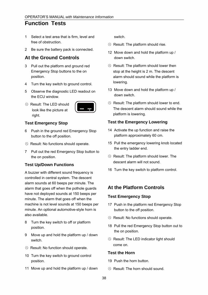
5 Observe the diagnostic LED readout on
the ECU window.
⊙ Result: The LED should
look like the picture at
right.
Test Emergency Stop
6 Push in the ground red Emergency Stop
button to the off position.
⊙ Result: No functions should operate.
7 Pull out the red Emergency Stop button to
the on position.
Test Up/Down Functions
A buzzer with different sound frequency is
controlled in central system. The descent
alarm sounds at 60 beeps per minute. The
alarm that goes off when the pothole guards
have not deployed sounds at 150 beeps per
minute. The alarm that goes off when the
machine is not level sounds at 150 beeps per
minute. An optional automotive-style horn is
also available.
8 Turn the key switch to off or platform
position.
9 Move up and hold the platform up / down
switch.
⊙ Result: No function should operate.
10 Turn the key switch to ground control
position.
11 Move up and hold the platform up / down
switch.
⊙ Result: The platform should rise.
12 Move down and hold the platform up /
down switch.
⊙ Result: The platform should lower then
stop at the height is 2 m. The descent
alarm should sound while the platform is
lowering.
13 Move down and hold the platform up /
down switch.
⊙ Result: The platform should lower to end.
The descent alarm should sound while the
platform is lowering.
Test the Emergency Lowering
14 Activate the up function and raise the
platform approximately 60 cm.
15 Pull the emergency lowering knob located
the entry ladder end.
⊙ Result: The platform should lower. The
descent alarm will not sound.
16 Turn the key switch to platform control.
At the Platform Controls
Test Emergency Stop
17 Push in the platform red Emergency Stop
button to the off position.
⊙ Result: No functions should operate.
18 Pull the red Emergency Stop button out to
the on position.
⊙ Result: The LED indicator light should
come on.
Test the Horn
19 Push the horn button.
⊙ Result: The horn should sound.

OPERATOR’S MANUAL with Maintenance Information
Function Tests
39
Test Function Enable and Up/Down
Functions
20 Do not hold the function enable switch on
the control handle.
21 Slowly move the control handle in the
direction indicated by the blue arrow, then
in the direction indicated by the yellow
arrow.
⊙ Result: No functions should operate.
22 Press the lift function select button.
23 Press and hold the function enable switch
on the control handle.
24 Slowly move the control handle in the
direction indicated by the blue arrow.
⊙ Result: The platform should raise. The
pothole guards should deploy.
25 Release the control handle.
⊙ Result: The platform should stop raising.
26 Press and hold the function enable switch.
Slowly move the control handle in the
direction indicated by the yellow arrow.
⊙ Result: The platform should lower. The
descent alarm should sound while the
platform is lowering.
Test the Steering
Note: When performing the steer and drive
function tests, stand in the platform facing the
steer end of the machine.
27 Press the drive function select switch.
28 Press and hold the function enable switch
on the control handle.
29 Depress the thumb rocker switch on top of
the control handle in the direction identified
by the blue left arrow on the control panel.
⊙ Result: The steer wheels should turn in the
direction that the blue left arrow points on
the control panel.
30 Depress the thumb rocker switch in the
direction identified by the white right arrow
on the control panel.
⊙ Result: The steer wheels should turn in the
direction that the white right arrow points
on the control panel.
Test Drive and Braking
31 Press and hold the function enable switch
on the control handle.
32 Slowly move the control handle in the
direction indicated by the blue up arrow on
the control panel until the machine begins
to move, then return the handle to the
center position.
⊙ Result: The machine should move in the
direction that the blue up arrow points on
the control panel, then come to an abrupt
stop.
33 Press and hold the function enable switch
on the control handle.
34 Slowly move the control handle in the
direction indicated by the yellow down
arrow on the control panel until the
machine begins to move, then return the
handle to the center position.
⊙ Result: The machine should move in the
direction that the yellow down arrow points
on the control panel, then come to an
abrupt stop.
Note: The brakes must be able to hold the
machine on any slope it is able to climb.
Test Limited Drive Speed
35 Press and hold the lift function enable
switch. Raise the platform approximately
2m from the ground.
⊙ Result: The pothole guards should deploy.
36 Press and hold the function enable switch
on the control handle.
OPERATOR’S MANUAL with Maintenance Information
Function Tests
40
37 Slowly move the control handle to the full
drive position.
⊙ Result: The maximum achievable drive
speed with the platform raised should not
exceed 20 cm/s.
¤ Result: If the drive speed with the platform
raised exceeds 20 cm/s, immediately tag
and remove the machine from service.
Test the Tilt Sensor Operation
Note: Perform this test from the ground with
the platform controller. Do not stand in the
platform.
38 Fully lower the platform.
39 Place a 3.5x20cm or similar piece of wood
under both wheels on one side and drive
the machine up onto them.
40 Raise the platform at least 2m.
⊙ Result: The platform should stop and the tilt
alarm will sound at 180 beeps per minute.
41 Move the drive control handle in the
direction indicated by the blue up arrow,
then move the drive control handle in the
direction indicated by the white down
arrow.
⊙ Result: The drive function should not work
in either direction.
42 Lower the platform and drive the machine
off the block.
Test the Pothole Guards
Note: The pothole guards should automatically
deploy when the platform is raised. The
pothole guards activate another limit switch
which allows the machine to continue to
function. If the pothole guards do not deploy,
an alarm sounds and the machine will not
drive.
43 Raise the platform.
⊙ Result: When the platform is raised 2m
from the ground, the pothole guards should
deploy.
44 Press on the pothole guards on one side,
and then the other.
⊙ Result: The pothole guards should not
move.
45 Lower the platform.
⊙ Result: The pothole guards should return to
the stowed position.
46 Place a 3.5x20cm or similar piece of wood
under a pothole guard. Raise the platform.
⊙ Result: Before the platform is raised 2m
from the ground, an alarm should sound
and the drive function should not Work.
47 Lower the platform and remove the
3.5x20cm wood block.
OPERATOR’S MANUAL with Maintenance Information
Operating Instructions
41
Do Not Operate Unless:
√ You learn and practice the principles of
safe machine operation contained in this
operator's manual.
1 Avoid hazardous situations.
2 Always perform a pre-operation
inspection.
3 Inspect the workplace.
4 Always perform function tests prior to
use.
5 Only use the machine as it was
intended.
Fundamentals
This machine is a self-propelled hydraulic lift
equipped with a work platform on the scissor
mechanism. Vibrations emitted by these
machines are not hazardous to an operator in
the work platform. The machine can be used
to position personnel with their tools and
supplies at position above ground level and
can be used to reach work areas located
above and over machinery or equipment.
A full and detailed implementation of EN ISO
13849-1/2 is correctly applied on our MEWP
design. SISTEMA, a software tool for PL
Calculation Tool, is also used to perform some
relatively straightforward calculations on
subsystem to determine the overall PL of the
system. Reliability data, diagnostic coverage
[DC], the system architecture [Category],
common cause failure and, where relevant,
requirements for software are used to assess
the PL to comply with PLr of SRP/CS in
Clause 5.11 of EN 280.
The Operating Instructions section provides
instructions for each aspect of machine
operation.
It is the operator's responsibility to follow all
the safety rules and instructions in the
operator's manual.
Using the machine for anything other than
lifting personnel, along with their tools and
materials, to an aerial work site is unsafe and
dangerous.
Only trained and authorized personnel should
be permitted to operate a machine. If more
than one operator is expected to use a
machine at different times in the same work
shift, they must all be qualified operators and
are all expected to follow all safety rules and
instructions in the operator's manual. That
means every new operator should perform a
pre-operation inspection, function tests, and a
workplace inspection before using the
machine.

OPERATOR’S MANUAL with Maintenance Information
Operating Instructions
42
Emergency Stop
Push in the red Emergency Stop button to the
off position at the ground controls or the
platform controls to stop all machine functions.
Repair any function that operates when either
red Emergency Stop button is pushed in.
Emergency Lowering
1 Pull the emergency lowering knob.
Operation from Ground
1 Turn the key switch to ground control.
2 Pull out both ground and platform red
Emergency Stop buttons to the on
position.
3 Be sure the battery pack is connected
before operating the machine.
To Position Platform
1 Move the up/down toggle switch according
to the markings on the control panel.
Drive and steer functions are not available
from the ground controls.
Operation from Platform
1 Turn the key switch to platform control.
2 Pull out the ground and platform red
Emergency Stop buttons to the on
position.
3 Be sure the battery pack is connected
before operating the machine.
To Position Platform
1 Press the lift function select button.
2 Press and hold the lift function enable
switch on the control handle.
3 Move the control handle according to the
markings on the control panel.
To Steer
1 Press the drive function select button.
2 Press and hold the function enable switch
on the control handle.
3 Turn the steer wheels with the thumb
rocker switch located on the top of the
control handle.
To Drive
1 Press the drive function select button.
2 Press and hold the function enable switch
on the control handle.
3 Increase speed: Slowly move the control
handle off center.
Decrease speed: Slowly move the control
handle toward center.
Stop: Return the control handle to center or
release the function enable switch.
Use the color-coded direction arrows on the
platform controls to identify the direction the
machine will travel.
Machine travel speed is restricted when the
platform is raised.
Battery condition will affect machine
performance. Machine drive speed and
function speed will drop when the battery level
indicator is flashing.
To reduce drive speed
The drive controls can operate in two different
drive speed modes. When the drive speed
button light is on, slow drive speed mode is
active. When the button light is off, fast drive
speed mode is active.
Press the drive speed button to select the
desired drive speed.

OPERATOR’S MANUAL with Maintenance Information
Operating Instructions
43
Driving on a slope
Determine the slope and side slope ratings for
the machine and determine the slope grade.
S0608, S0808, S0812, S1012, S1212, S1412
Maximum slope rating, stowed position 25%,
Maximum side slope rating, stowed position
25%
Note: Slope rating is subject to ground
conditions and adequate traction.
Press the drive speed button to the fast drive
speed mode.
To determine the slope grade
Measure the slope with a digital inclinometer
OR use the following procedure.
You will need:
Carpenter’s level
Straight piece of wood, at least 1 m long
Tape measure
Lay the piece of wood on the slope.
At the downhill end, lay the level on the top
edge of the piece of wood and lift the end until
the piece of wood is level.
While holding the piece of wood level,
measure the distance from the bottom of the
piece of wood to the ground.
Divide the tape measure distance (rise) by the
length of the piece of wood (run) and multiply
by 100.
Example:
Run = 3.6 m
Rise = 0.3 m
0.3 m ÷ 3.6 m = 0.083 x 100 = 8.3%
If the slope exceeds the maximum slope or
side slope rating, the machine must be
winched or transported up or down the slope.
See Transport and Lifting section.
Operation from Ground with
Controller
Maintain safe distances between operator,
machine and fixed objects.
Be aware of the direction the machine will
travel when using the controller.
Battery Level Indicator
Full Low
Use the LED diagnostic readout to determine
the battery level.
How to use the Safety Arm
1 Raise the platform approximately 2.5 m
from the ground.
2 Lift the safety arm, move it to the center of
the scissor arm and rotate up to a vertical
position.
3 Lower the platform until the safety arm
rests securely on the link. Keep clear of
the safety arm when lowering the platform.
Don’t engage the safety arm
unless unload the platform.
How to Fold Down the
Guardrails
The platform railing system consists of three
fold down rail section for the extension deck
and three sections for the main deck. All
sections are held in place by four wire lock
pins.
1 Fully lower the platform and retract the
platform extension.
2 Remove the platform controls.

OPERATOR’S MANUAL with Maintenance Information
Operating Instructions
44
3 From inside the platform, remove the two
front extension deck wire lock pins.
4 Fold down the front rail assembly. Keep
hands clear of pinch points.
5 Replace the two removed pins back into
each side rail bracket.
6 Fold down the extension platform right rail
assembly. Keep hands clear of pinch
points.
7 Fold down the extension platform left rail
assembly. Keep hands clear of pinch
points.
8 Carefully open the gate and move to the
rear step or the ground.
9 From the rear step or from the ground,
remove the right rear main deck wire lock
pins.
10 Fold down the right rail assembly. Keep
hands clear of pinch points.
11 Replace the removed pin back into rear rail
bracket.
12 Remove the left rear main deck wire lock
pins.
13 Fold down the left rail assembly. Keep
hands clear of pinch points.
14 Replace the removed pin back into rear rail
bracket.
15 Fold down the rear rail assemble. Keep
hands free of pinch points.
How to Raise the Guardrails
Follow the fold down instructions but in reverse
order.
To Extend and Retract Platform
1 Press the platform lock pin pedal on the
extension deck by foot.
2 Push the platform extension guardrail to
extend the platform to the desired position.
Do not stand on the platform extension
while trying to extend it.

OPERATOR’S MANUAL with Maintenance Information
Operating Instructions
45
Error indicator readout
If the LED diagnostic readout displays an error code, such as LL, push in and pull
out the red Emergency Stop button to reset the system.
List of Fault Codes
Display Description Lift Reaction
01 System initialization Fault Disables All Motion
02 System communication Fault Disables All Motion
03 Invalid option setting Fault Disables All Motion
12 Chassis Up/Down Switch ON at Power-up Fault Disable Chassis Control
18 Pothole Guard Fault Disable Lifting and Driving
31 Pressure Sensor Fault Disables All Motion
32 Angle Sensor Fault Disables All Motion
34 Reserved
42 Platform Left Turn Switch ON at power-up Message Diagnostic Message Only
43 Platform Right Turn Switch ON at power-up Message Diagnostic Message Only
46 Platform Joystick Enable Switch ON at power-up Fault Disable Platform Control
47 Platform Joystick not in neutral at power-up Message Diagnostic Message Only
52 Drive Forward Coil Fault Disable Lifting and Driving
53 Drive Reverse Coil Fault Disable Lifting and Driving
54 Lift Up Coil Fault Disable Lifting and Driving
55 Lift Down Coil Fault Disable Lifting and Driving
56 Right Turn Coil Fault Disable Lifting and Driving
57 Left Turn Coil Fault Disable Lifting and Driving
58 General Brake Coil Fault Disable Lifting and Driving
59 Parallel Coil Fault Disable Lifting and Driving
61 Motor Controller Current Sensor Fault Controller Dependent
62 Motor Controller Hardware Failsafe Fault Controller Dependent

OPERATOR’S MANUAL with Maintenance Information
Operating Instructions
46
Display Description Lift Reaction
63 Motor Controller Motor Output Fault Controller Dependent
64 Motor Controller SRO Fault Controller Dependent
65 Motor Controller Throttle Fault Controller Dependent
66 Motor Controller Emergency Reverse Fault Controller Dependent
67 Motor Controller HPD Fault Controller Dependent
68 Low Voltage Fault Disable All Motion
69 High Neutral Current Fault (ZAPI Only) Disable All Motion
70 Steering Input Out of Range (ZAPI Only) Disable All Motion
71 Motor Controller Main Contactor Fault Disable Lifting and Driving
72 Motor Controller Over Voltage Fault Controller Dependent
73 Motor Controller Thermal Cutback Fault Controller Dependent
74 Motor Controller Motor Fault Controller Dependent
75 Motor Controller Pump Motor Fault Controller Dependent
76 Motor Controller Left Drive Motor Fault Controller Dependent
77 Motor Controller Right Drive Motor Fault Controller Dependent
78 Pump Motor Short Fault Disable Lifting and Driving
79 Left Drive Motor Short Fault Disable Lifting and Driving
80 Over 80% Load Warning Warning Only
81 Right Drive Motor Short Fault Disable Lifting and Driving
82 Right Brake Coil Fault Disable Lifting and Driving
83 Left Brake Coil Fault Disable Lifting and Driving
90 Over 90% Load Warning Warning Only
99 Over 99% Load Warning Warning Only
OL Overloaded Platform Fault Disable All Motion
LL Machine Tilted Beyond Safe Limits Fault Disable Lifting and Driving

OPERATOR’S MANUAL with Maintenance Information
Operating Instructions
47
Troubleshooting Guide
Display Description
01 System Initialization Fault: ECU may be malfunctioning, replace it.
02 System Communication Fault: Check communications cable connections and other wiring. If that does not resolve the problem, try replacing the PCU or ECU.
03 Invalid Option setting Fault: Set appropriate option for this lift.
12 Chassis Toggle Switch ON at power-up Fault: Check the wires to the Toggle Switch or look for a stuck Toggle Switch.
18 Pothole Guard Fault: Check that the pothole guards are extended, check the pothole limit switches. Check wires to the switches, check the down limit switch and connections.
31 Pressure Sensor Fault: Check the wiring to the sensor and then the sensor itself. Also check to make sure that the correct option is properly selected (or not) for load sensing.
32 Angle Sensor Fault: Check the wiring to the sensor and then the sensor itself. Also check to make sure that the correct option is properly selected (or not) for load sensing
42 Platform Left Turn Switch ON at power-up Message: Ensure that nothing is holding the Joystick Toggle Switches down. If OK, consider replacing the Joystick or PCU.
43 Platform Right Turn Switch ON at power-up Message: Ensure that nothing is holding the Joystick Toggle Switches down. If OK, consider replacing the Joystick or PCU.
46 Platform Joystick Enable Switch ON at power-up Fault: Ensure that nothing is holding the Enable switch closed. Also check the neutral zone parameters. If OK, consider replacing the Joystick or PCU.
47 Platform Joystick not in neutral at power-up Message: Make sure that the Joystick is in the neutral (upright) position. Check the neutral zone parameter setting in Dingli Scissor Programmer. If it’s OK, consider replacing the Joystick or the PCU.
52 Drive Forward Coil Fault: Check the connections to the Coil’s terminals and make sure they are tight. If so, check the coil itself to see if it is open or shorted.
53 Drive Reverse Coil Fault: Check the connections to the Coil’s terminals and make sure they are tight. If so, check the coil itself to see if it is open or shorted.
54 Lift Up Coil Fault: Check the connections to the Coil’s terminals and make sure they are tight. If so, check the coil itself to see if it is open or shorted.
55 Lift Down Coil Fault: Check the connections to the Coil’s terminals and make sure they are tight. If so, check the coil itself to see if it is open or shorted.
56 Right Turn Coil Fault: Check the connections to the Coil’s terminals and make sure they are tight. If so, check the coil itself to see if it is open or shorted.
57 Left Turn Coil Fault: Check the connections to the Coil’s terminals and make sure they are tight. If so, check the coil itself to see if it is open or shorted.
58 General Brake Coil Fault: Check the connections to the Coil’s terminals and make sure they are tight. If so, check the coil itself to see if it is open or shorted.

OPERATOR’S MANUAL with Maintenance Information
Operating Instructions
48
Display Description
59 Parallel Coil Fault: Check the connections to the Coil’s terminals and make sure they are tight. If so, check the coil itself to see if it is open or shorted.
61 Motor Controller Current Sensor Fault: Drive or Lift Motor may be overheating. Let the lift cool down. If that does not help, cycle power to reset the Motor controller. If the problem persists, check the wiring and if OK, try replacing the Motor Controller.
62 Motor Controller Hardware Failsafe Fault: Cycle power. If that does not resolve the issue check for noise sources. If still needed, try replacing the Motor Controller.
63 Motor Controller Motor Output fault: Check wiring first then cycle power. If needed replace controller.
64 Motor Controller SRO Fault: Look at motor enable delay with the Dingli Scissor Programmer, it may be too short. Make sure other Motor Controller parameters are properly selected.
65 Motor Controller Throttle Fault: Check wiring. Make sure the correct throttle type is selected in the Motor Controller.
67 Motor Controller HPD Fault: Look at motor enable delay with the Dingli Scissor Programmer, it may be too short. Make sure other Motor Controller parameters are properly selected.
68 Low Voltage Fault: Check battery voltage and charge batteries if necessary. Check the battery connections and tighten or clean. Check the voltage to the ECU and PCU.
69
High Neutral Current: The MC is sensing current in the motors when there should not be. This could occur anytime the MC thinks the brakes are on and the motors are still turning. This message sometimes comes just before other faults but should be ignored in those cases.
70
Steering Input Out of Range: There is an inappropriate voltage at the steering input of the ZAPI motor controller. The ZAPI may need to be “trained” for the three steering voltages (on Differential Steered machines). Or the steering voltage from the ECU was at some point outside of the range that was recorded during the “training” session. Retrain the ZAPI and/or check for fluctuating voltages due to lose wires, etc.
71 Motor Controller Main Contactor Fault: Check the connections to the main contactor. Replace the contactor if necessary. Replace the Motor Controller if necessary.
72 Motor Controller Over Voltage Fault: Check battery voltage and make sure the battery charger is not on. The cycle power to the lift. If that does not resolve the issue, try replacing the Motor Controller.
73 Motor Controller Thermal Cutback Fault: Drive or Lift Motor may be overheating. Let the lift cool down. If that does not help cycle power to reset the Motor controller. If that doesn’t resolve the issue, replace the Motor Controller.
74 Motor Controller Motor Fault: Check connections to the motors. Cycle power to the lift and if that does not resolve the issue, replace the Motor Controller.
75 Motor Controller Pump Motor Fault: Check connections to the Pump Motor. Cycle power to the lift and if that does not resolve the issue, replace the Motor Controller.
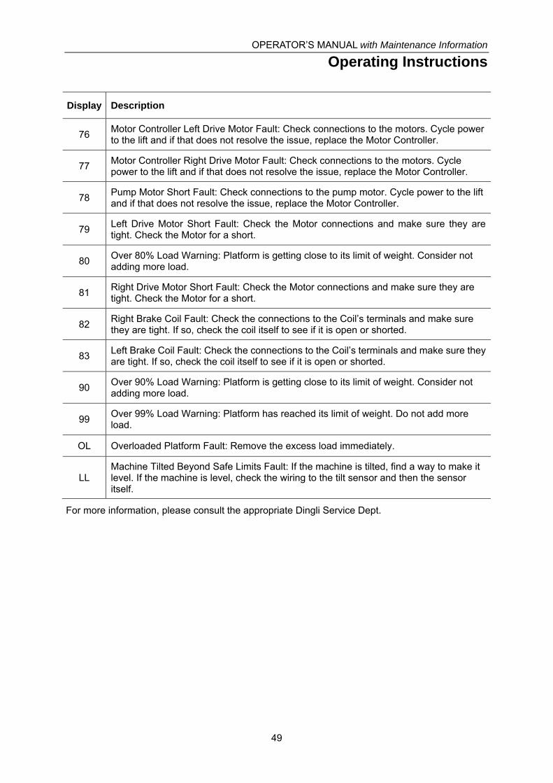
OPERATOR’S MANUAL with Maintenance Information
Operating Instructions
49
Display Description
76 Motor Controller Left Drive Motor Fault: Check connections to the motors. Cycle power to the lift and if that does not resolve the issue, replace the Motor Controller.
77 Motor Controller Right Drive Motor Fault: Check connections to the motors. Cycle power to the lift and if that does not resolve the issue, replace the Motor Controller.
78 Pump Motor Short Fault: Check connections to the pump motor. Cycle power to the lift and if that does not resolve the issue, replace the Motor Controller.
79 Left Drive Motor Short Fault: Check the Motor connections and make sure they are tight. Check the Motor for a short.
80 Over 80% Load Warning: Platform is getting close to its limit of weight. Consider not adding more load.
81 Right Drive Motor Short Fault: Check the Motor connections and make sure they are tight. Check the Motor for a short.
82 Right Brake Coil Fault: Check the connections to the Coil’s terminals and make sure they are tight. If so, check the coil itself to see if it is open or shorted.
83 Left Brake Coil Fault: Check the connections to the Coil’s terminals and make sure they are tight. If so, check the coil itself to see if it is open or shorted.
90 Over 90% Load Warning: Platform is getting close to its limit of weight. Consider not adding more load.
99 Over 99% Load Warning: Platform has reached its limit of weight. Do not add more load.
OL Overloaded Platform Fault: Remove the excess load immediately.
LL Machine Tilted Beyond Safe Limits Fault: If the machine is tilted, find a way to make it level. If the machine is level, check the wiring to the tilt sensor and then the sensor itself.
For more information, please consult the appropriate Dingli Service Dept.

OPERATOR’S MANUAL with Maintenance Information
Operating Instructions
50
Battery and Charger
Instructions
Observe and Obey:
√ Do not use an external charger or booster
battery.
√ Charge the battery in a well-ventilated area.
√ Use proper AC input voltage for charging
as indicated on the charger.
√ Use only a Dingli authorized battery and
charger.
To Charge Battery
1 Be sure the batteries are connected before
charging the batteries.
2 Open the battery compartment. The
compartment should remain open for the
entire charging cycle.
Maintenance - free batteries
3 Connect the battery charger to a grounded
AC circuit.
4 The charger will indicate when the battery
is fully charged.
Standard Batteries
5 Remove the battery vent caps and check
the battery acid level. If necessary, add
only enough distilled water to cover the
plates. Do not overfill prior to the charge
cycle.
6 Replace the battery vent caps.
7 Connect the battery charger to a grounded
AC circuit.
8 The charger will indicate when the battery
is fully charged.
9 Check the battery acid level when the
charging cycle is complete. Replenish with
distilled water to the bottom of the fill tube.
Do not overfill.
Dry Battery Filling and
Charging Instructions
1 Remove the battery vent caps and
permanently remove the plastic seal from
the battery vent openings.
2 Fill each cell with battery acid (electrolyte)
until the level is sufficient to cover the
plates.
Do not fill to maximum level until the battery
charge cycle is complete. Overfilling can
cause the battery acid to overflow during
charging. Neutralize battery acid spills with
baking soda and water.
3 Install the battery vent caps.
4 Charge the battery.
5 Check the battery acid level when the
charging cycle is complete. Replenish with
distilled water to the bottom of the fill tube.
Do not overfill.

OPERATOR’S MANUAL with Maintenance Information
Transport and Lifting Instructions
51
Observe and Obey:
√ Common sense and planning must be
applied to control the movement of the
machine when lifting it with a crane or
forklift.
√ Only qualified aerial lift operators should
move the machine on or off the truck.
√ The transport vehicle must be parked on a
level surface.
√ The transport vehicle must be secured to
prevent rolling while the machine is being
loaded.
√ Be sure the vehicle capacity, loading
surfaces and chains or straps are sufficient
to withstand the machine weight. See the
serial label for the machine weight.
√ The machine must be on a level surface or
secured before releasing the brakes.
√ Do not allow the rails to fall when the snap
pins are removed. Maintain a firm grasp on
the rails when the rails are lowered.
√ Do not drive the machine on a slope that
exceeds the slope or side slope rating. See
Driving on a Slope in the Operating
Instructions section.
√ If the slope of the transport vehicle bed
exceeds the maximum slope rating, the
machine must be loaded and unloaded
using a winch as described.
Brake Release Operation
For the Hydraulic Motor Drive Model
1 Chock the wheels to prevent the machine
from rolling.
2 Be sure the winch line is properly secured
to the drive chassis tie points and the path
is clear of all obstructions.
3 Push in the black brake release knob to
open the brake valve.
4 Pump the red brake release pump knob.
For the DC Motor Drive Model
1 Chock the wheels to prevent the machine
from rolling.
2 Pull out the red Emergency Stop button on
both the ground and platform controls to
the on position.
3 Press and hold lift switch to “down”
position in ground control, meanwhile turn
on the key switch to the "Ground" position.
The brake will be released after Alarm
alerts.
4 If you want to close the brake release, just
turn off the key switch in “ground” position.
Towing the Hydraulic Drive Model is not
recommended. If the machine must be towed,
do not exceed 3.5 km/h.
Towing the DC Motor Drive Model is not
recommended. If the machine must be towed,
do not exceed 4.1 km/h.

OPERATOR’S MANUAL with Maintenance Information
Transport and Lifting Instructions
52
Securing to Truck or Trailer for
Transit
Always chock the machine wheels in
preparation for transport.
Retract and secure the extension deck(s).
Turn the key switch to the off position and
remove the key before transporting.
Inspect the entire machine for loose or
unsecured items.
Use the tie-down points on the chassis for
anchoring down to the transport surface.
Use a minimum of four chains or straps.
Use chains or straps of ample load capacity.
If the railings have been folded down, secure
them with straps before transporting.

OPERATOR’S MANUAL with Maintenance Information
Transport and Lifting Instructions
53
Observe and Obey:
√ Only qualified riggers should rig and lift the
machine.
√ Only qualified forklift operators should lift
the machine with a forklift.
√ Be sure the crane capacity, loading
surfaces and straps or lines are sufficient to
withstand the machine weight. See the
serial plate for the machine weight.
Lifting the Machine with a
Forklift
Be sure the extension deck, controls and
component trays are secure. Remove all loose
items on the machine.
Fully lower the platform. The platform must
remain lowered during all loading and
transport procedures.
Use the forklift pockets located on both sides
of the ladder.
Position the forklift forks in position with the
forklift pockets.
Drive forward to the full extent of the forks.
Raise the machine 6 in / 15 cm and then tilt the
forks back slightly to keep the machine secure.
Be sure the machine is level when lowering
the forks.
Lifting the machine from the
side can result in component damage.
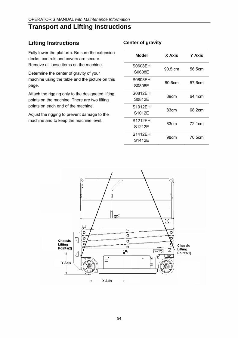
OPERATOR’S MANUAL with Maintenance Information
Transport and Lifting Instructions
54
Lifting Instructions
Fully lower the platform. Be sure the extension
decks, controls and covers are secure.
Remove all loose items on the machine.
Determine the center of gravity of your
machine using the table and the picture on this
page.
Attach the rigging only to the designated lifting
points on the machine. There are two lifting
points on each end of the machine.
Adjust the rigging to prevent damage to the
machine and to keep the machine level.
Center of gravity
Model X Axis Y Axis
S0608EH
S0608E 90.5 cm 56.5cm
S0808EH
S0808E 80.6cm 57.6cm
S0812EH
S0812E 89cm 64.4cm
S1012EH
S1012E 83cm 68.2cm
S1212EH
S1212E 83cm 72.1cm
S1412EH
S1412E 98cm 70.5cm

OPERATOR’S MANUAL with Maintenance Information
Maintenance
55
Observe and Obey:
√ Only routine maintenance items specified in
this manual shall be performed by the
operator.
√ Scheduled maintenance inspections shall
be completed by qualified service
technicians, according to the manufacturer's
specifications and the requirements
specified in this manual.
Maintenance Symbols Legend
The following symbols have
been used in this manual to help communicate
the intent of the instructions. When one or
more of the symbols appear at the beginning
of a maintenance procedure, it conveys the
meaning below.
Indicates that tools will be required to
perform this procedure.
Indicates that new parts will be
required to perform this procedure.
Indicates that dealer service will be
required to perform this procedure.
Pre-delivery Preparation Report
The pre-delivery preparation report contains
checklists for each type of scheduled
inspection.
Make copies of the Pre-delivery Preparation
report to use for each inspection. Store
completed forms as required.
Maintenance Schedule
There are five types of maintenance
inspections that must be performed according
to a schedule— daily, quarterly, semi-annually,
annually, and two year. The Scheduled
Maintenance Procedures Section and the
Maintenance Inspection Report have been
divided into five subsections—A, B, C, D, and
E. Use the following chart to determine which
group(s) of procedures are required to perform
a scheduled inspection.
Inspection Checklist
Daily or every 8 hours A
Quarterly or every 250 hours A+B
Semi-annually or every 500 hours A+B+C
Annually or every 1000 hours A+B+C+D
Two year or every 2000 hours A+B+C+D+E
Maintenance Inspection Report
The maintenance inspection report contains
checklists for each type of scheduled
inspection.
Make copies of the Maintenance Inspection
Report to use for each inspection. Maintain
completed forms for a minimum of 4 years or
in compliance with your employer, jobsite and
governmental regulations and requirements.

OPERATOR’S MANUAL with Maintenance Information
Maintenance
56
Pre-delivery Preparation Report
Fundamentals
It is the responsibility of the dealer to perform
the Pre-delivery Preparation.
The Pre-delivery Preparation is performed
prior to each delivery. The inspection is
designed to discover if anything is apparently
wrong with a machine before it is put into
service.
A damaged or modified machine must never
be used. If damage or any variation from
factory delivered condition is discovered, the
machine must be tagged and removed from
service.
Repairs to the machine may only be made by
a qualified service technician, according to the
manufacturer’s specifications.
Scheduled maintenance inspections shall be
performed by qualified service technicians,
according to the manufacturer’s specifications
and the requirements listed in this manual.
Instructions
Use the operator’s manual on your machine.
The Pre-delivery Preparation consists of
completing the Pre-operation Inspection, the
Maintenance items and the Function Tests.
Use this form to record the results. Place a
check in the appropriate box after each part is
completed. Follow the instructions in the
operator’s manual.
If any inspection receives an N, remove the
machine from service, repair and re-inspect it.
After repair, place a check in the R box.
Legend
Y = yes, completed
N = no, unable to complete
R = repaired
Comments
Pre-Delivery Preparation Y N R
Pre-operation inspection
completed
Maintenance items
completed
Function tests completed
Model
Serial number
Date
Machine owner
Inspected by (print)
Inspector signature
Inspector title
Inspector company

OPERATOR’S MANUAL with Maintenance Information
Maintenance
57
Maintenance Inspection Report
Model
Serial number
Date
Hour meter
Machine owner
Inspected by (print)
Inspector signature
Inspector title
Inspector company
Instructions
• Make copies of this report to use for each
inspection.
• Select the appropriate checklist(s) for the
type of inspection to be performed.
□ Daily or 8 hours Inspection:
A
□ Quarterly or 250 hours Inspection:
A+ B
□ Semi-annually or 500 hours Inspection:
A+B+C
□ Annually or 1000 hours Inspection:
A+B+C+D
□ Two year or 2000 hours Inspection:
A+B+C+D+E
• Place a check in the appropriate box after
each inspection procedure is completed.
• Use the step-by-step procedures in this
section to learn how to perform these
inspections.
• If any inspection receives an “N”, tag and
remove the machine from service, repair and
re-inspect it. After repair, place a check in the
“R’ box.
Legend
Y = yes, acceptable
N = no, remove from service
R = repaired
Checklist A Y N R
A-1 Inspect the manuals and decals
A-2 Pre-operation inspection
A-3 Check the Batteries
A-4 Check the Hydraulic Oil Level
A-5 Function tests
Perform after 40 hours:
A-6 30 day service
Perform every 100 hours:
A-7 Grease steer yokes
Checklist B Y N R
B-1 Batteries
B-2 Electrical wiring
B-3 Tires and wheels
B-4 Emergency stop
B-5 Key switch
B-6 Horn (if equipped)
B-7 Drive brakes
B-8 Drive speed - stowed
B-9 Drive speed - raised
B-10 Drive speed - slow
B-11 Hydraulic oil analysis
B-12 Tank venting system
B-13 Latch components
B-14 Test the down and pothole limit switches
B-15 Test the up limit switches
Checklist C Y N R
C-1 Platform overload (if equipped)
C-2 Breather cap - models with optional oil
Checklist D Y N R
D-1 Scissor arm wear pads
D-2 Hydraulic filter
Checklist E Y N R
E-1 Hydraulic oil

OPERATOR’S MANUAL with Maintenance Information
Maintenance
58
Checklist A Procedures
A-1
Inspect the Manuals and Decals
Maintaining the operator’s manual in good
condition is essential to safe machine
operation. Manuals are included with each
machine and should be stored in the container
provided in the platform. An illegible or missing
manual will not provide safety and operational
information necessary for a safe operating
condition.
In addition, maintaining all of the safety and
instructional decals in good condition is
mandatory for safe machine operation. Decals
alert operators and personnel to the many
possible hazards associated with using this
machine. They also provide users with
operation and maintenance information. An
illegible decal will fail to alert personnel of a
procedure or hazard and could result in unsafe
operating conditions.
1 Check to make sure that the operator
manual is present and complete in the
storage container on the platform.
2 Examine the pages of manual to be sure
that they are legible and in good condition.
⊙ Result: The operator manual is appropriate
for the machine and the manual are legible
and in good condition.
¤ Result: The operator’s manual is not
appropriate for the machine or the manual
is not in good condition or is illegible.
Remove the machine from service until the
manual is replaced.
3 Open the operator’s manual to the decals
inspection section. Carefully and
thoroughly inspect all decals on the
machine for legibility and damage.
⊙ Result: The machine is equipped with all
required decals, and all decals are legible
and in good condition.
¤ Result: The machine is not equipped with
all required decals, or one or more decals
are illegible or in poor condition. Remove
the machine from service until the decals
are replaced.
4 Always return the manual to the storage
container after use.
Note: Contact your authorized DINGLI
distributor or DINGLI Industries if replacement
manuals or decals are needed.

OPERATOR’S MANUAL with Maintenance Information
Maintenance
59
A-2
Perform Pre-operation Inspection
Completing a Pre-operation Inspection is
essential to safe machine operation. The
Pre-operation Inspection is a visual inspection
performed by the operator prior to each work
shift. The inspection is designed to discover if
anything is apparently wrong with a machine
before the operator performs the function tests.
The Pre-operation Inspection also serves to
determine if routine maintenance procedures
are required.
Complete information to perform this
procedure is available in the appropriate
operator’s manual. Refer to the Operator’s
Manual on your machine.
A-3
Check the Batteries
Proper battery condition is essential to good
machine performance and operational safety.
Improper fluid levels or damaged cables and
connections can result in component damage
and hazardous conditions.
Electrocution hazard.
Contact with hot or live circuits may result in
death or serious injury. Remove all rings,
watches and other jewelry.
Bodily injury hazard.
Batteries contain acid. Avoid spilling or
contacting battery acid. Neutralize battery acid
spills with baking soda and water.
1 Put on protective clothing and eye wear.
2 Be sure that the battery cable connections
are tight and free of corrosion.
3 Be sure that the battery hold-down bars
are secure.
4 Remove the battery vent caps.
5 Check the battery acid level. If needed,
replenish with distilled water to the bottom
of the battery fill tube. Do not overfill.
6 Install the vent caps.

OPERATOR’S MANUAL with Maintenance Information
Maintenance
60
A-4
Check the Hydraulic Oil Level
Maintaining the hydraulic oil at the proper level
is essential to machine operation. Improper
hydraulic oil levels can damage hydraulic
components. Daily checks allow the inspector
to identify changes in oil level that might
indicate the presence of hydraulic system
problems.
Perform this procedure
with the platform in the stowed position and
the engine off.
1 Visually inspect the sight of hydraulic oil
level from the side of the hydraulic oil tank.
⊙ Result: The hydraulic oil level should be
within the top 5 cm of the tank.
2 Add oil if necessary. Do not overfill.
Hydraulic oil specifications
L-HV46
A-5
Perform Function Tests
Completing the function tests is essential to
safe machine operation. Function tests are
designed to discover any malfunctions before
the machine is put into service. A
malfunctioning machine must never be used. If
malfunctions are discovered, the machine
must be tagged and removed from service.
Complete information to perform this
procedure is available in the appropriate
operator’s manual. Refer to the Operator’s
Manual on your machine.

OPERATOR’S MANUAL with Maintenance Information
Maintenance
61
A-6
Perform 30 Day Service
The 30 day maintenance procedure is a one
time procedure to be performed after the first
30 days or 40 hours of usage. After this
interval, refer to the maintenance tables for
continued scheduled maintenance.
1 Perform the following maintenance
procedures:
• B-3 Inspect the Tires, Wheels and Castle
Nut Torque
• D-2 Replace the Hydraulic Tank Return
Filter Element
A-7
Grease the Steer Yokes
DINGLI requires that this procedure be
performed every 100 hours of operation.
Regular application of lubrication to the steer
yokes is essential to good machine
performance and service life. Continued use of
an insufficiently greased steer yoke will result
in component damage.
1 Open the steer yoke cover.
2 Locate the grease add hole on the top of
the steer yoke.
3 Pump multipurpose grease into the steer
yoke until the steer yoke is full and grease
is being forced past the bearings.
4 Install the cover.
5 Repeat this step for the other steer yoke.
Grease Specification
Chevron Ultra-duty grease, EP NLGI 1 (lithium
based) or equivalent
OPERATOR’S MANUAL with Maintenance Information
Maintenance
62
Checklist B Procedures
B-1
Inspect the Batteries
DINGLI requires that this procedure be
performed every 250 hours or quarterly,
whichever comes first.
Proper battery condition is essential to good
machine performance and operational safety.
Improper fluid levels or damaged cables and
connections can result in component damage
and hazardous conditions.
Electrocution / burn hazard.
Contact with electrically charged circuits could
result in death or serious injury. Remove all
rings, watches and other jewelry.
Bodily injury hazard.
Batteries contain acid. Avoid spilling or
contacting battery acid. Neutralize battery acid
spills with baking soda and water.
1 Put on protective clothing and eye wear.
2 Release the battery pack latch and rotate
the battery pack out and away from the
chassis.
3 Be sure that the battery cable connections
are free of corrosion.
Note: Adding terminal protectors and a
corrosion preventative sealant will help
eliminate corrosion on the battery terminals
and cables.
4 Be sure that the battery retainers and
cable connections are tight.
5 Fully charge the batteries. Allow the
batteries to rest 24 hours before
performing this procedure to allow the
battery cells to equalize.
Models without maintenance-free or sealed
batteries:
6 Remove the battery vent caps and check
the specific gravity of each battery cell with
a hydrometer. Note the results.
7 Check the ambient air temperature and
adjust the specific gravity reading for each
cell as follows:
• Add 0.004 to the reading of each cell for
every 5.5° C above 26.7° C.
• Subtract 0.004 from the reading of each
cell for every 5.5° C below 26.7° C.
⊙ Result: All battery cells display an adjusted
specific gravity of 1.277 or higher. The
battery is fully charged. Proceed to step 11.
¤ Result: One or more battery cells display a
specific gravity of 1.217 or below. Proceed
to step 8.
8 Perform an equalizing charge OR fully
charge the batteries and allow the
batteries to rest at least 6 hours.
9 Remove the battery vent caps and check
the specific gravity of each battery cell with
a hydrometer. Note the results.
10 Check the ambient air temperature and
adjust the specific gravity reading for each
cell as follows:
• Add 0.004 to the reading of each cell for
every 5.5° C above 26.7° C.
• Subtract 0.004 from the reading of each
cell for every 5.5° C below 26.7° C.
⊙ Result: All battery cells display a specific
gravity of 1 .277 or greater. The battery is
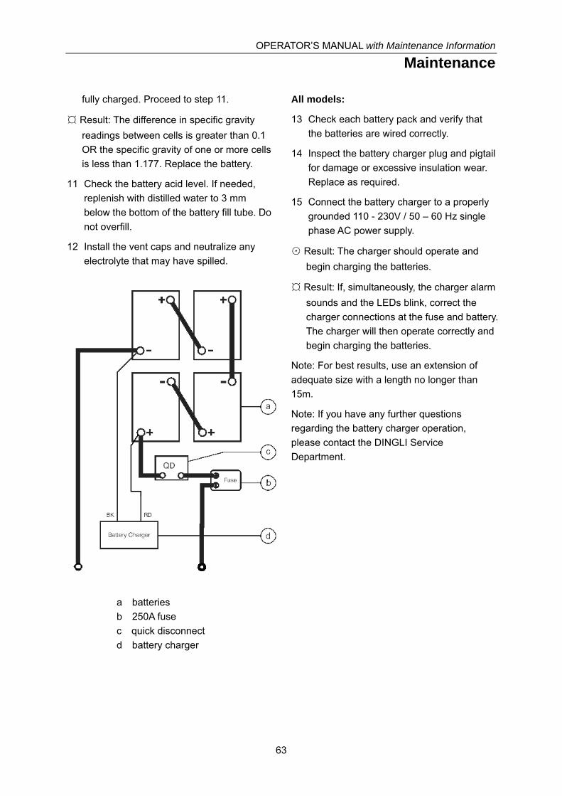
OPERATOR’S MANUAL with Maintenance Information
Maintenance
63
fully charged. Proceed to step 11.
¤ Result: The difference in specific gravity
readings between cells is greater than 0.1
OR the specific gravity of one or more cells
is less than 1.177. Replace the battery.
11 Check the battery acid level. If needed,
replenish with distilled water to 3 mm
below the bottom of the battery fill tube. Do
not overfill.
12 Install the vent caps and neutralize any
electrolyte that may have spilled.
a batteries
b 250A fuse
c quick disconnect
d battery charger
All models:
13 Check each battery pack and verify that
the batteries are wired correctly.
14 Inspect the battery charger plug and pigtail
for damage or excessive insulation wear.
Replace as required.
15 Connect the battery charger to a properly
grounded 110 - 230V / 50 – 60 Hz single
phase AC power supply.
⊙ Result: The charger should operate and
begin charging the batteries.
¤ Result: If, simultaneously, the charger alarm
sounds and the LEDs blink, correct the
charger connections at the fuse and battery.
The charger will then operate correctly and
begin charging the batteries.
Note: For best results, use an extension of
adequate size with a length no longer than
15m.
Note: If you have any further questions
regarding the battery charger operation,
please contact the DINGLI Service
Department.

OPERATOR’S MANUAL with Maintenance Information
Maintenance
64
B-2
Inspect the Electrical Wiring
DINGLI requires that this procedure be
performed every 250 hours or quarterly,
whichever comes first.
Maintaining electrical wiring in good condition
is essential to safe operation and good
machine performance. Failure to find and
replace burnt, chafed, corroded or pinched
wires could result in unsafe operating
conditions and may cause component
damage.
Electrocution / burn hazard.
Contact with electrically charged circuits could
result in death or serious injury. Remove all
rings, watches and other jewelry.
1 Inspect the underside of the chassis for
damaged or missing ground strap(s).
2 Inspect the following areas for burnt,
chafed, corroded and loose wires:
• Ground control panel
• Hydraulic power unit module tray
• Battery pack module tray
• Platform controls
3 Turn the key switch to ground control and
pull out the red Emergency Stop button to
the on position at both the ground and
platform controls.
4 Raise the platform approximately 2.5 m
from the ground.
5 Lift the safety arm, move it to the center of
the scissor arm and rotate up to a vertical
position.
6 Lower the platform onto the safety arm.
Crushing hazard. Keep
hands clear of the safety arm when lowering
the platform.
7 Inspect the center chassis area and
scissor arms for burnt, chafed and pinched
cables.
8 Inspect the following areas for burnt,
chafed, corroded, pinched and loose
wires:
• Scissor arms
• ECU to platform controls
• Power to platform wiring
9 Inspect for a liberal coating of dielectric
grease in the following locations:
• Between the ECU and platform controls
• All wire harness connectors Level sensor
10 Raise the platform and return the safety
arm to the stowed position.
11 Lower the platform to the stowed position
and turn the machine off.

OPERATOR’S MANUAL with Maintenance Information
Maintenance
65
B-3
Inspect the Tires and Wheels
(including castle nut torque)
DINGLI requires that this procedure be
performed every 250 hours or quarterly,
whichever comes first.
Maintaining the tires and wheels in good
condition is essential to safe operation and
good performance. Tire and/or wheel failure
could result in a machine tip-over. Component
damage may also result if problems are not
discovered and repaired in a timely fashion.
1 Check the tire surface and sidewalls for
cuts, cracks, punctures and unusual wear.
2 Check each wheel for damage, bends and
cracks.
For HD model machine
3 Remove the cotter pin and check each
castle nut for proper torque.
Note: Always replace the cotter pin with a new
one when removing the castle nut or when
checking the torque of the castle nut.
4 Install a new cotter pin. Bend the cotter pin
to lock it in place.
Castle nut torque, dry 406.7Nm
Castle nut torque, lubricated 305Nm
For DC model machine
3 Check each bolt for proper torque.
Bolt torque, dry 50.5Nm
Bolt torque, lubricated 37.8Nm
B-4
Test the Emergency Stop
DINGLI requires that this procedure be
performed every 250 hours or quarterly,
whichever comes first.
A properly functioning Emergency Stop is
essential for safe machine operation. An
improperly operating red Emergency Stop
button will fail to shut off power and stop all
machine functions, resulting in a hazardous
situation.
As a safety feature, selecting and operating
the ground controls will override the platform
controls, except the platform red Emergency
Stop button.
1 Turn the key switch to ground control and
pull out the red Emergency Stop button to
the on position at both the ground and
platform controls.
2 Push in the red Emergency Stop button at
the ground controls to the off position.
⊙ Result: No machine functions should
operate.
3 Turn the key switch to platform control and
pull out the red Emergency Stop button to
the on position at both the ground and
platform controls.
4 Push down the red Emergency Stop button
at the platform controls to the off position.
⊙ Result: No machine functions should
operate.
Note: The red Emergency Stop button at the
ground controls will stop all machine operation,
even if the key switch is switched to platform
control.

OPERATOR’S MANUAL with Maintenance Information
Maintenance
66
B-5
Test the Key Switch
DINGLI requires that this procedure be
performed every 250 hours or quarterly,
whichever comes first.
Proper key switch action and response is
essential to safe machine operation. The
machine can be operated from the ground or
platform controls and the activation of one or
the other is accomplished with the key switch.
Failure of the key switch to activate the
appropriate control panel could cause a
hazardous operating situation.
Perform this procedure from the ground using
the platform controls. Do not stand in the
platform.
1 Pull out the red Emergency Stop button to
the on position at both the ground and
platform controls.
2 Turn the key switch to platform control.
3 Check the platform up/down function from
the ground controls.
⊙ Result: The machine functions should not
operate.
4 Turn the key switch to ground control.
5 Check the machine functions from the
platform controls.
⊙ Result: The machine functions should not
operate.
6 Turn the key switch to the off position.
⊙ Result: No function should operate.
B-6
Test the Automotive-style Horn (if
equipped)
DINGLI requires that this procedure be
performed every 250 hours or quarterly,
whichever comes first.
The horn is activated at the platform controls
and sounds at the ground as a warning to
ground personnel. An improperly functioning
horn will prevent the operator from alerting
ground personnel of hazards or unsafe
conditions.
1 Turn the key switch to platform control and
pull out the red Emergency Stop button to
the on position at both the ground and
platform controls.
2 Push down the horn button at the platform
controls.
⊙ Result: The horn should sound.

OPERATOR’S MANUAL with Maintenance Information
Maintenance
67
B-7
Test the Drive Brakes
DINGLI requires that this procedure be
performed every 250 hours or quarterly,
whichever comes first.
Proper brake action is essential to safe
machine operation. The drive brake function
should operate smoothly, free of hesitation,
jerking and unusual noise.
Hydraulically-released individual wheel brakes
can appear to operate normally when not fully
operational.
Perform this procedure with the machine on a
firm level surface that is free of obstructions,
with the platform extension deck fully retracted
and the platform in the stowed position.
1 Mark a test line on the ground for
reference.
2 Turn the key switch to platform control and
pull out the red Emergency Stop button to
the on position at both the ground and
platform controls.
3 Lower the platform to the stowed position.
4 Press the drive function select button.
a
a drive function select button
5 Choose a point on the machine; i.e.,
contact patch of a tire, as a visual
reference for use when crossing the test
line.
6 Bring the machine to top drive speed
before reaching the test line. Release the
function enable switch or the joystick when
your reference point on the machine
crosses the test line.
7 Measure the distance between the test line
and your machine reference point.
⊙ Result: The machine stops within the
specified braking distance. No action
required.
¤ Result: The machine does not stop within
the specified braking distance.
Note: The brakes must be able to hold the
machine on any slope it is able to climb.
8 Replace the brakes and repeat this
procedure beginning with step 1.
Braking distance, maximum
High range on paved surface 61cm±30cm

OPERATOR’S MANUAL with Maintenance Information
Maintenance
68
B-8
Test the Drive Speed - Stowed
Position
DINGLI requires that this procedure be
performed every 250 hours or quarterly,
whichever comes first.
Proper drive functions are essential to safe
machine operation. The drive function should
respond quickly and smoothly to operator
control. Drive performance should also be free
of hesitation, jerking and unusual noise over
the entire proportionally controlled speed
range.
Perform this procedure with the machine on a
firm, level surface that is free of obstructions.
1 Create start and finish lines by marking
two lines on the ground 12.2 m apart.
2 Turn the key switch to platform control and
pull out the red Emergency Stop button to
the on position at both the ground and
platform controls.
3 Lower the platform to the stowed position.
4 Press the drive function select button.
a
a drive function select button
5 Choose a point on the machine; i.e.,
contact patch of a tire, as a visual
reference for use when crossing the start
and finish lines.
6 Bring the machine to top drive speed
before reaching the start line. Begin timing
when your reference point on the machine
crosses the start line.
7 Continue at full speed and note the time
when your reference point on the machine
passes over the finish line. Refer to
specifications.

OPERATOR’S MANUAL with Maintenance Information
Maintenance
69
B-9
Test the Drive Speed - Raised
Position
DINGLI requires that this procedure be
performed every 250 hours or quarterly,
whichever comes first.
Proper drive functions are essential to safe
machine operation. The drive function should
respond quickly and smoothly to operator
control. Drive performance should also be free
of hesitation, jerking and unusual noise over
the entire proportionally controlled speed
range.
Perform this procedure with the machine on a
firm, level surface that is free of obstructions.
1 Create start and finish lines by marking
two lines on the ground 12.2 m apart.
2 Turn the key switch to platform control and
pull out the red Emergency Stop button to
the on position at both the ground and
platform controls.
3 Press the lift function select button.
a b
a lift function select button
b drive function select button
4 Press and hold the function enable switch
on the joystick.
5 Raise the platform approximately 1.2 m
from the ground.
6 Press the drive function select button.
7 Choose a point on the machine; i.e.,
contact patch of a tire, as a visual
reference for use when crossing the start
and finish lines.
8 Bring the machine to top drive speed
before reaching the start line. Begin timing
when your reference point on the machine
crosses the start line.
9 Continue at full speed and note the time
when your reference point on the machine
passes over the finish line. Refer to
specifications.

OPERATOR’S MANUAL with Maintenance Information
Maintenance
70
B-10
Test the Slow Drive Speed
DINGLI requires that this procedure be
performed every 250 hours or quarterly,
whichever comes first.
Proper drive functions are essential to safe
machine operation. The drive function should
respond quickly and smoothly to operator
control. Drive performance should also be free
of hesitation, jerking and unusual noise over
the entire proportionally controlled speed
range.
Perform this procedure with the machine on a
firm, level surface that is free of obstructions.
1 Create start and finish lines by marking
two lines on the ground 12.2 m apart.
2 Turn the key switch to platform control and
pull out the red Emergency Stop button to
the on position at both the ground and
platform controls.
3 Lower the platform to the stowed position.
4 Press the slow speed select button.
a
a slow speed select button
5 Choose a point on the machine; i.e.,
contact patch of a tire, as a visual
reference for use when crossing the start
and finish lines.
6 Bring the machine to top drive speed
before reaching the start line. Begin timing
when your reference point on the machine
crosses the start line.
7 Continue at full speed and note the time
when your reference point on the machine
passes over the finish line. The time is less
than 25 sec.

OPERATOR’S MANUAL with Maintenance Information
Maintenance
71
B-11
Perform Hydraulic Oil Analysis
DINGLI requires that this procedure be
performed every 250 hours or quarterly,
whichever comes first.
Replacement or testing of the hydraulic oil is
essential for good machine performance and
service life. Dirty oil may cause the machine to
perform poorly and continued use may cause
component damage. Extremely dirty
conditions may require oil changes to be
performed more often.
Before replacing the hydraulic oil, the oil may
be tested by an oil distributor for specific levels
of contamination to verify that changing the oil
is necessary.
If the hydraulic oil is not replaced at the two
year inspection, test the oil quarterly. Replace
the oil when it fails the test. See E-1, Test or
Replace the Hydraulic Oil.
B-12
Inspect the Hydraulic Tank Cap
Venting System
DINGLI requires that this procedure be
performed quarterly or every 250 hours,
whichever comes first. Perform this procedure
more often if dusty conditions exist.
A free-breathing hydraulic tank cap is essential
for good machine performance and service life.
A dirty or clogged cap may cause the machine
to perform poorly. Extremely dirty conditions
may require that the cap be inspected more
often.
1 Remove the breather cap from the
hydraulic tank.
2 Check for proper venting.
⊙ Result: Air passes through the breather
cap.
¤ Result: If air does not pass through the cap,
clean or replace the cap. Proceed to step
3.
Note: When checking for positive tank cap
venting, air should pass freely through the cap.
3 Using a mild solvent, carefully wash the
cap venting system. Dry using low
pressure compressed air. Repeat step 2.
4 Install the breather cap onto the hydraulic
tank.

OPERATOR’S MANUAL with Maintenance Information
Maintenance
72
B-13
Check the Module Tray Latch
Components
DINGLI requires that this procedure be
performed every 250 hours or quarterly,
whichever comes first.
Maintaining the module tray latch components
in good condition is essential to good
performance and service life. Failure to detect
worn out latch components may result in
module trays opening unexpectedly, creating
an unsafe operating condition.
1 Inspect each module tray rotary latch and
related components for wear. Tighten any
loose fasteners.
2 Lubricate each module tray rotary latch.
Using light oil, apply a few drops to each of
the springs and to the sides of the rotary
latch mechanism.
B-14
Test the Down Limit Switch and the
Pothole Limit Switches
DINGLI requires that this procedure be
performed every 250 hours or quarterly,
whichever comes first.
Maintaining the limit switches is essential to
safe operation and good machine
performance. Operating the machine with a
faulty limit switch could result in reduced
machine performance and a potentially unsafe
operating condition.
Perform these procedures with the machine on
a firm, level surface that is free of obstructions.
Down Limit Switch
1 Remove the platform controls from the
platform.
2 Raise the platform approximately 2.5 m
from the ground.
3 Lift the safety arm, move it to the center of
the scissor arm and rotate up to a vertical
position.
4 Lower the platform onto the safety arm.
Crushing hazard. Keep
hands clear of the safety arm when lowering
the platform.
5 Turn the key switch to the off position.
6 Tag and disconnect the platform control
box at the platform.
7 Follow the platform control cable down the
scissor stack to the underside of the
chassis deck. Tag and disconnect the
platform cable from the ECU cable at the
6-pin Deutsch connector under the chassis
deck.
8 Securely install the platform control box
OPERATOR’S MANUAL with Maintenance Information
Maintenance
73
harness plug into the 6-pin Deutsch
connector of the ECU cable.
9 Open the down limit switch cover, tag and
disconnect the wires of the down limit
switch wire harness.
10 Turn the key switch to platform control.
11 Raise the platform and return the safety
arm to the stowed position.
12 Working at the platform controls, press the
lift function select button. Lower the
platform to the stowed position.
⊙ Result: The diagnostic display will show
code 18, an alarm sounds and the lift
function should operate. The machine is
functioning properly.
¤ Result: The diagnostic display does not
show code 18, the alarm does not sound
and the lift function should not operate.
Replace the down limit switch.
13 Press the drive function select button.
Attempt to drive the machine.
⊙ Result: The diagnostic display will show
code 18, an alarm sounds, and the steer
and drive functions should not operate. The
machine is functioning properly.
¤ Result: The diagnostic display does not
show code 18, the alarm does not sound,
and the steer and drive functions operate.
Replace the down limit switch.
14 Press the lift function select button. Raise
the platform approximately 0.3 m.
⊙ Result: The diagnostic display will show
code 18 and an alarm sounds. The
machine is functioning properly.
¤ Result: The diagnostic display does not
show code 18 and the alarm does not
sound. Replace the down limit switch.
15 Raise the platform until the pothole guards
are deployed.
⊙ Result: The diagnostic display does not
show code 18 and the alarm does not
sound. The machine is functioning
properly.
¤ Result: The diagnostic display shows code
18 and an alarm sounds. Replace the
down limit switch.
16 Raise the platform approximately 2.5 m
from the ground.
17 Lift the safety arm, move it to the center of
the scissor arm and rotate up to a vertical
position.
18 Lower the platform onto the safety arm.
Crushing hazard. Keep
hands clear of the safety arm when lowering
the platform.
19 Turn the key switch to the off position.
20 Disconnect the platform controls from the
ECU cable.
21 Securely install the connector of the ECU
cable into the platform control cable.
22 Working at the platform, securely install
the connector of the platform controls into
the platform control cable.
23 Securely connect the two wires of the
down limit switch to wire harness.
24 Close and install the switch cover.
25 Turn the key switch to platform control.
26 Raise the platform and return the safety
arm to the stowed position.
27 Lower the platform to the stowed position.
Pothole Limit Switches
28 Move the machine onto a grade which
exceeds the rating of the level sensor.
Refer to the serial label on the machine.
29 Press the lift function select button.
Standing on the up-hill side of the machine,

OPERATOR’S MANUAL with Maintenance Information
Maintenance
74
attempt to raise the platform to
approximately 2 m.
⊙ Result: The diagnostic display shows code
LL, an alarm sounds, and the machine
stops lifting after the pothole guards are
deployed. The machine is functioning
properly.
¤ Result: The diagnostic display does not
show code LL, the alarm does not sound
and the machine will continue to lift the
platform after the pothole guards are
deployed. Adjust or replace the pothole
limit switch.
30 Press the drive function select button.
Standing on the up-hill side of the machine,
attempt to steer and drive the machine.
⊙ Result: The diagnostic display shows code
LL, an alarm sounds, and the machine will
not steer or drive. The machine is
functioning properly.
¤ Result: The diagnostic display does not
show code LL, the alarm does not sound
and the steer and drive functions operate.
Adjust or replace the pothole limit switch.
31 Lower the platform to the stowed position.
Move the machine onto a firm, level
surface.
32 Place a wooden block approximately 5 cm
tall under the right pothole guard.
33 Press the lift function select button.
Attempt to raise the platform
approximately 2m.
⊙ Result: The pothole guard contacts the
block and does not fully deploy, the
diagnostic display shows code 18, an
alarm sounds and the platform will lift to 2m
or beyond. The machine is functioning
properly.
¤ Result: The pothole guard contacts the
block and does not fully deploy, the
diagnostic display does not show code 18,
the alarm does not sound and the machine
will continue to lift the platform after the
pothole guards are deployed. Adjust or
replace the pothole limit switch.
34 Press the drive function select button.
Attempt to steer or drive the machine.
⊙ Result: The diagnostic display shows code
18, an alarm sounds, and the machine will
not steer or drive. The machine is
functioning properly.
¤ Result: The diagnostic display does not
show code 18, the alarm does not sound
and the steer and drive functions operate.
Adjust or replace the down limit switch.
35 Lower the platform to the stowed position
and remove the block under the right
pothole guard.
36 Repeat this procedure beginning with step
31 for the left pothole guard.
37 Lower the platform to the stowed position,
remove the block under the left pothole
guard.
38 Turn off the machine.

OPERATOR’S MANUAL with Maintenance Information
Maintenance
75
B-15
Test the Up Limit Switch
DINGLI requires that this procedure be
performed every 250 hours or quarterly,
whichever comes first.
Maintaining the limit switches is essential to
safe operation and good machine
performance.
Operating the machine with a faulty limit switch
could result in reduced machine performance
and a potentially unsafe operating condition.
Perform these procedures with the machine on
a firm, level surface that is free of obstructions.
1 Turn the key switch to ground control and
raise the platform approximately 2.5m from
the ground.
2 Lift the safety arm, move it to the center of
the scissor arm and rotate the safety arm
away from the machine and let it hang
down.
3 Lower the platform onto the safety arm.
Crushing hazard. Keep
hands clear of the safety arm when lowering
the platform.
4 Open the limited switch house cover from
the chassis.
5 While raising the platform from the ground
controls, push in the roller of the up limit
switch to activate the limit switch.
⊙ Result: The platform stops raising. The
machine is functioning properly.
¤ Result: The platform continues to raise.
Adjust or replace the up limit switch.
6 Install the limited switch house cover to
chassis.
7 Put the safe arm to home position.
8 Lower the platform to the stowed position.

OPERATOR’S MANUAL with Maintenance Information
Maintenance
76
Checklist C Procedures
C-1
Test the Platform Overload System (if
equipped)
DINGLI requires that this procedure be
performed every 500 hours or six months,
whichever comes first OR when the machine
fails to lift the maximum rated load.
Testing the platform overload system regularly
is essential to safe machine operation.
Continued use of an improperly operating
platform overload system could result in the
system not sensing an overloaded platform
condition. Machine stability could be
compromised resulting in the machine tipping
over.
The platform overload system is designed to
prevent machine operation in the event the
platform is overloaded. Models equipped with
the platform overload option are provided with
two additional machine control components:
the overload pressure switch and a tilt sensor.
The overload pressure switch, which is
adjustable and located at the barrel-end of the
lift cylinder, is used to determine when the
hydraulic lift cylinder requires too much
pressure to support the load inside the
platform. When this occurs, the pressure
switch will send a signal to the ECU, which will
not allow the machine to function until the
extra weight is removed from the platform.
The tilt sensor, located in the inner scissor arm
1, is used to determine the tilt of scissor, than
to measure the height of platform.
a overload pressure switch
b tilt sensor
c limited switch cover
1 Turn the key switch to ground control and
raise the platform approximately 2.5 m
from the ground.
2 Lift the safety arm, move it to the center of
the scissor arm and rotate the safety arm
away from the machine and let it hang
down.
3 Lower the platform onto the safety arm.
Crushing hazard. Keep
hands clear of the safety arm when lowering
the platform.
4 Open the limited switch house cover from
the chassis.
5 Open the up limited switch cover.

OPERATOR’S MANUAL with Maintenance Information
Maintenance
77
a
bc
a up limited switch
b down limited switch
c slope sensor
6 Tag and disconnect the wires of the up
limit switch wire harness.
7 Securely connect together the terminals of
the two wires of the up limit switch.
8 Turn the key switch to ground control and
pull out the red Emergency Stop button to
the on position at both the ground and
platform controls.
9 Raise the platform to release the safe arm.
10 Put the safe arm to home position.
11 Fully raise the platform. Release the toggle
switch.
⊙ Result: The alarm should sound.
¤ Result: The alarm does not sound.
Calibrate the platform overload system.
12 Using the manual lowering knob, lower the
platform to the stowed position.
13 Securely connect the wires of the up limit
switch.
14 Fully raise the platform. Release the toggle
switch.
⊙ Result: The alarm should not sound. The
system is functioning correctly.
¤ Result: The alarm sounds. The system is
not functioning correctly. Troubleshoot the
limit switch, limit switch wire harness or
limit switch mount bracket or the platform
overload system needs to be calibrated.
15 Lower the platform approximately 2.5 m
from the ground.
16 Lift the safety arm, move it to the center of
the scissor arm and rotate the safety arm
away from the machine and let it hang
down.
17 Lower the platform onto the safety arm.
Crushing hazard. Keep hands
clear of the safety arm when lowering the
platform.
18 Install the up limited switch cover.
19 Install the limited switch house cover.
20 Raise the platform to release the safe arm.
21 Put the safe arm to home position.
22 Lower the platform to the stowed position.

OPERATOR’S MANUAL with Maintenance Information
Maintenance
78
C-2
Replace the Hydraulic Tank Breather
Cap
DINGLI requires that this procedure be
performed every 500 hours or semi-annually,
whichever comes first.
The hydraulic tank is a vented-type tank. The
breather cap has an internal air filter that can
become clogged or, over time, can deteriorate.
If the breather cap is faulty or improperly
installed, impurities can enter the hydraulic
system which may cause component damage.
Extremely dirty conditions may require that the
cap be inspected more often.
1 Remove and discard the hydraulic tank
breather cap.
2 Install a new cap onto the tank.

OPERATOR’S MANUAL with Maintenance Information
Maintenance
79
Checklist D Procedures
D-1
Check the Scissor Arm Wear Pads
DINGLI requires that this procedure be
performed every 1000 hours or annually,
whichever comes first.
Maintaining the condition of the scissor arm
wear pads is essential to safe machine
operation. Continued use of worn out wear
pads may result in component damage and
unsafe operating conditions.
Perform this procedure with the platform in the
stowed position.
1 Measure the distance between the number
one inner arm cross tube and the chassis
deck at the ground controls side of the
non-steer end of the machine.
Refer to illustration below.
⊙ Result: The measurement is 34mm or more.
Proceed to step 2.
¤ Result: The measurement is less than
34mm. Replace both wear pads.
a wear pad
b inner arm cross tube
c chassis deck
2 Measure the distance between the number
one inner arm cross tube and the chassis
deck at the battery pack side of the
non-steer end of the machine.
Refer to illustration below.
⊙ Result: The measurement is 34mm or more.
Proceed to step 3.
¤ Result: The measurement is less than 34
mm. Replace both wear pads.
3 Apply a thin layer of dry film lubricant to the
area of the chassis where the scissor arm
wear pads make contact.

OPERATOR’S MANUAL with Maintenance Information
Maintenance
80
D-2
Replace the Hydraulic Tank Return
Filter Element
DINGLI requires that this procedure be
performed every 1000 hours or annually,
whichever comes first.
Replacement of the hydraulic tank return filter
is essential for good machine performance
and service life. A dirty or clogged filter may
cause the machine to perform poorly and
continued use may cause component damage.
Extremely dirty conditions may require that the
filter be replaced more often.
Beware of hot oil. Contact
with hot oil may cause severe burns.
The hydraulic tank return
filter is mounted on the bracket between the
function manifold and the hydraulic power unit.
1 Clean the area around the oil filter.
Remove the filter with an oil filter wrench.
2 Apply a thin layer of oil to the new oil filter
gasket.
3 Install the new filter and tighten it securely
by hand.
4 Use a permanent ink marker to write the
date and number of hours from the hour
meter onto the filter.
5 Turn the key switch to ground control and
pull out the red Emergency Stop button to
the on position at both the ground and
platform controls.
6 Activate and hold the platform up toggle
switch.
7 Inspect the filter and related components
to be sure that there are no leaks.
8 Clean up any oil that may have spilled.
OPERATOR’S MANUAL with Maintenance Information
Maintenance
81
Checklist E Procedure
E-1
Test or Replace the Hydraulic Oil
DINGLI requires that this procedure be
performed every 2000 hours or every two
years, whichever comes first.
Replacement or testing of the hydraulic oil is
essential for good machine performance and
service life. Dirty oil may cause the machine to
perform poorly and continued use may cause
component damage. Extremely dirty
conditions may require oil changes to be
performed more often.
Before replacing the hydraulic oil, the oil may
be tested by an oil distributor for specific levels
of contamination to verify that changing the oil
is necessary.
If the hydraulic oil is not replaced at the two
year inspection, test the oil quarterly. Replace
the oil when it fails the test.
Note: Perform this procedure with the platform
in the stowed position.
1 Disconnect the battery pack from the
machine.
Electrocution / burn hazard:
Contact with electrically charged circuits could
result in death or serious injury. Remove all
rings, watches and other jewelry.
2 Open the power unit module tray.
3 Tag and disconnect the hydraulic tank
return line from the hydraulic filter head
and remove the line from the tank. Cap the
fitting on the filter head.
4 Tag and disconnect the hydraulic pump
inlet line and remove the line from the tank.
Cap the fitting on the pump.
5 Remove the hydraulic tank retaining
fasteners and remove the hydraulic tank
from the machine.
6 Remove the oil drain plug at bottom.
7 Drain all of the oil into a suitable container..
Bodily injury hazard. Spraying
hydraulic oil can penetrate and burn skin.
Loosen hydraulic connections very slowly to
allow the oil pressure to dissipate gradually.
Do not allow oil to squirt or spray.
8 Clean up any oil that may have spilled.
Properly discard the used oil.
9 Clean the inside of the hydraulic tank using
a mild solvent. Allow the tank to dry
completely.
10 Tighten the drain plug. Torque to
specification.
Torque specifications
Hydraulic tank drain plug, dry 4.5Nm
Hydraulic tank drain plug, lubricated 3.4Nm
11 Install the hydraulic tank and install and
tighten the hydraulic tank retaining
fasteners. Torque to specification.
Torque specifications
Hydraulic tank retaining fasteners, dry 4Nm
Hydraulic tank drain plug, lubricated 2.9Nm
12 Install the hydraulic pump inlet line into the
tank. Install the fitting onto the pump and
torque.

OPERATOR’S MANUAL with Maintenance Information
Maintenance
82
13 Install the hydraulic pump return line into
the tank. Install the fitting onto the
hydraulic filter head and torque.
14 Fill the tank with hydraulic oil until the fluid
is full in the hydraulic tank. Do not overfill.
15 Activate the pump to fill the hydraulic
system with oil and bleed the system of air.
Component damage hazard.
The pump can be damaged if operated without
oil. Be careful not to empty the hydraulic tank
while in the process of filling the hydraulic
system. Do not allow the pump to cavitate.

OPERATOR’S MANUAL with Maintenance Information
Schematic
83
Hydraulic Schematic
S1012EH S1212EH S1412EH
1
2
PlatformOverload(Option)
L
1
2
SV
1
2
CV1
2
PlatformOverload(Option)
Upper LiftCylinder
L
1
2
SV
1
2
CV1
2
1
2
RV1
1
42
3 S2S1
SV1
12
RV1
1
2
1
2D1
D3
D4
D2
S1 L
BRKP T
M
1
1
1 2
1
2 RV2
12
RV3
1 2
CV2
1
2
34
FRRV1
1
2
ORF31
2
ORF4
3
2 4
1
SV2
34
2 1
SV3
4
231
5
SV4
1
2
CV1
1
2
ORF1
2 1
2
3
1
P41
P42

OPERATOR’S MANUAL with Maintenance Information
Schematic
84
S0608EH S0808EH S0812EH
1
2
PlatformOverload(Option)
L
1
2
SV
1
2
CV1
2
1
42
3 S2S1
SV1
12
RV1
1
2
1
2D1
D3
D4
D2
S1 L
BRKP T
M
1
1
1 2
1
2 RV2
12
RV3
1 2
CV2
1
2
34
FRRV1
1
2
ORF31
2
ORF4
3
2 4
1
SV2
34
2 1
SV3
4
231
5
SV4
1
2
CV1
1
2
ORF1
2 1
2
3
1
P41
P42
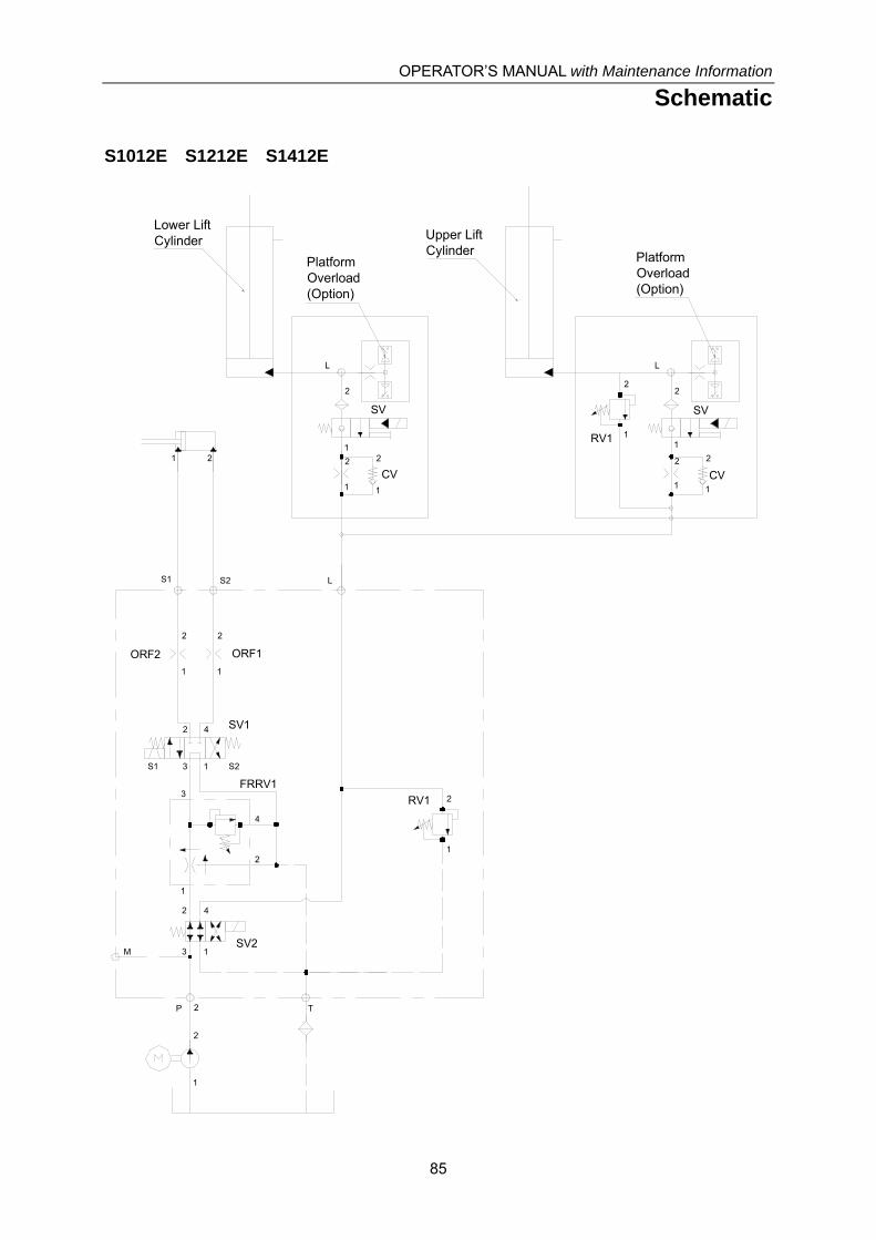
OPERATOR’S MANUAL with Maintenance Information
Schematic
85
S1012E S1212E S1412E
Lower LiftCylinder
1
42
3 S2S1
SV1
S1 S2 L
P T
M
2
1 2
1
2RV1
1
2
ORF2
1
2
ORF1
1
2
3
4
FRRV1
3
2 4
1SV2
1
2
PlatformOverload(Option)
L
1
2
SV
1
2
CV1
2
PlatformOverload(Option)
Upper LiftCylinder
L
1
2
SV
1
2
CV1
2
1
2
RV1
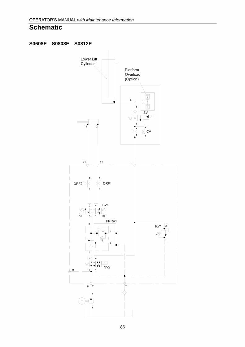
OPERATOR’S MANUAL with Maintenance Information
Schematic
86
S0608E S0808E S0812E
Lower LiftCylinder
1
42
3 S2S1
SV1
S1 S2 L
P T
M
2
1 2
1
2RV1
1
2
ORF2
1
2
ORF1
1
2
3
4
FRRV1
3
2 4
1SV2
1
2
PlatformOverload(Option)
L
1
2
SV
1
2
CV1
2
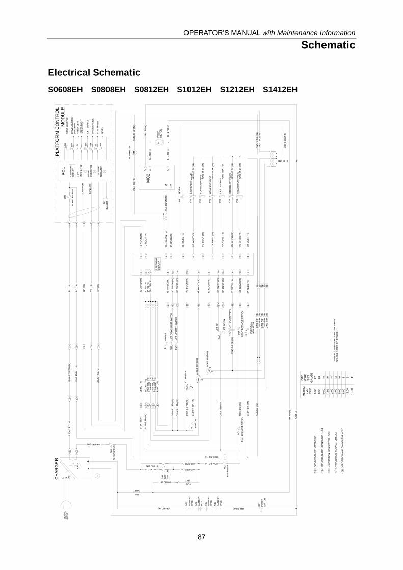
OPERATOR’S MANUAL with Maintenance Information
Schematic
87
Electrical Schematic
S0608EH S0808EH S0812EH S1012EH S1212EH S1412EH
B- BK (14)
ME
TR
ICS
IZE
mm
2
SA
EW
IRE
SIZ
EG
AU
GE
0.3
52
2
0.5
02
0
0.8
018
1.0
016
2.0
014
3.0
012
5.0
010
8.0
08
13
.00
6
19
.00
4
NO
TE
:ALL
WIR
ES
AR
E 1
8A
WG
OR
0.8
mm
UN
LES
S N
OT
ED
OT
HE
RW
ISE
BE
AC
ON
FU1
300A
L N PE
+-
CH
AR
GE
R
230
VA
CIN
PU
T
KA
CH
SA
1K
EY
SW
ITC
H
FU2
7A
HL1
BA
TT
ER
Y6
VD
C
GB
3
BA
TT
ER
Y6
VD
C
GB
4
010A-6 RD (14)
010-3 RD (14)
BA
TT
ER
Y6
VD
C
GB
2
BA
TT
ER
Y6
VD
C
GB
1
SB
2G
RO
UN
D E
MS
SB
1
PO
WE
RS
WIT
CH
BU
(1
6)
RD
(1
6)
WT
(1
6)
GN
(1
6)
YE
(16
)
4 15 23
SB
3
PLA
TF
OR
M E
MS
LIF
TIN
DIC
AT
OR
LO
W S
PE
ED
IND
ICA
TO
R
PC
U
DR
IVE
IND
ICA
TO
R
SB
4D
RIV
E J
OY
ST
ICK
DE
AD
MA
N
DR
IVE
JO
YS
TIC
K
S2
ST
EE
R L
EF
T
ST
EE
R R
IGH
T
SB
8
SB
7
SB
6
SB
5
B2
BU
ZZ
ER
LIF
T E
NA
BLE
DR
IVE
EN
AB
LE
LO
W S
PE
ED
HO
RN
JS1
KA
1E
MS
RE
LA
Y
TIL
T
LS
1L
OA
D S
EN
SO
R
TIL
T S
EN
SO
R
SQ
1
SQ
2
LIF
T U
P L
IMIT
SW
ITC
H
LIF
T D
OW
N L
IMIT
SW
ITC
H
AS
1A
NG
LE S
EN
SO
R
SA
2L
IFT
UP
LIF
T D
OW
N
B1
BU
ZZ
ER
LE
FT
PO
TH
OLE
SW
ITC
H
SQ
3S
Q4
LIF
T U
P V
ALV
EY
V1
ST
EE
R L
EF
T V
ALV
EY
V3
ST
EE
R R
IGH
T V
AL
VE
YV
4
B3
HO
RN
MC
2
M1
PU
MP
MO
TO
R
HM
HO
UR
ME
TE
R
7 S
EG
ME
NT
DIS
PL
AY
01
0A-9
RD
(16
)0
10A
-3 R
D (
16)
010
A-4
RD
(16
)0
10A
-5 R
D (
16)
5A
-2 R
D (
16)
B+
RD
(1
6)
=16
PO
SIT
ION
CO
NN
EC
TO
R L
OC
3
=6
PO
SIT
ION
AM
P C
ON
NE
CT
OR
LO
C7
=16
PO
SIT
ION
CO
NN
EC
TO
R L
OC
2
=9P
OS
ITIO
N A
MP
CO
NN
EC
TO
R L
OC
4
=2
PO
SIT
ION
AM
P C
ON
NE
CT
OR
F A B C D
001 RD (14)
A
010-2 RD (14) 010-4 RD (14)
010-1 RD (14)
010 RD (14)
01
0A R
D (
14)
B2
B R
D (
14)
CS4
010
A-7
RD
(14
)J
3 5 2 1
010-5 RD (14)
010
A-2
RD
(14
)
GN
D B
K (
14)
GN
D-2
BK
(14
)G
ND
-3 B
K (
14)
NM
2
1
010
A-1
RD
(14
)DEH G KF J
K
E
6A
YE
/VT
(1
6)
GN
D-1
4 B
K (
14)
GN
D-1
2 B
K (
14)
GN
D-5
BK
(14
)
MY
V2
LIF
T D
OW
N V
ALV
E
J1 J3
8A
-2 B
U (
16)
GN
D-1
0 B
K (
14)
GN
D-4
BK
(1
4)L
7 S
EG
ME
NT
DIS
PLA
Y
GN
D-1
BK
(1
4)
GN
D-6
BK
(1
4)
GN
D-1
0 B
K (
14)
GN
D-7
BK
(14
)G
ND
-8 B
K (
14)
GN
D-9
BK
(14
)
PLA
TF
OR
M C
ON
TR
OL
MO
DU
LE
B+
RD
(4)
B-
BK
(4)
B+
M-
B-
HL2 O
VE
RL
OA
DIN
DIC
AT
OR
B--
2 B
K (
4)
CA
N H
IGH
CA
N L
OW
2 F 4K9 K
GB- BK (4)
M--
2 B
K (
4)
B+
-4 R
D (
4)
GB+ RD (4)
010
A-5
-1 R
D (
16)
010
A-5
-2 R
D (
16)
010
A-5
-3 R
D (
16)
GN
D-9
-1 B
K (
14)
N P R
GN
D-7
-1 B
K (
14) R
IGH
T P
OT
HO
LE S
WIT
CH
10B
-3 B
U (
16)
B+
-2 R
D (
4)
13
2
1
1
3
3
2
2R
EV
ER
SE
VA
LVE
YV
6G
ND
-15
BK
(14
)
FO
RW
AR
D V
ALV
EY
V5
GN
D-1
4 B
K (
14)
LO
W S
PE
ED
VA
LVE
YV
7G
ND
-13
BK
(14
)
4A
RD
(16
)2
C R
D (
16)
5A
-1 R
D (
16)
9B
WH
/BK
(1
6)
12B
BN
/GY
(16
)
12A
BN
/GY
(16
)
11B
BU
/RD
(16
)
12C
BU
/GN
(16
)
11C
BU
/GN
(16
)
3C
RD
/GN
(16
)
4B
WH
/VT
(16
)
2B
GN
/RD
(14
)
10B
BU
/WH
(1
6)
6B
BU
/WH
(16
)
3A
YE
/BN
(16
)
1C
RD
/GN
(16
)
1B
YE
/GN
(16
)
8B
RD
/BN
(16
)
9A
BN
/BK
(16
)
8A
-1 B
N/G
N (
16)
7C
WH
/BU
(16
)
7B
WH
/BU
(16
)
7A
BN
/GY
(16
)
6C
BN
/GY
(1
6)
8C
WH
/VT
(16
)
3B
BK
/BN
(16
)
8A
-3 B
N/G
N (
16)
010
A-8
WH
/GN
(14
)
GN
D-1
BK
(14
)
010
B R
D/B
U (
14)
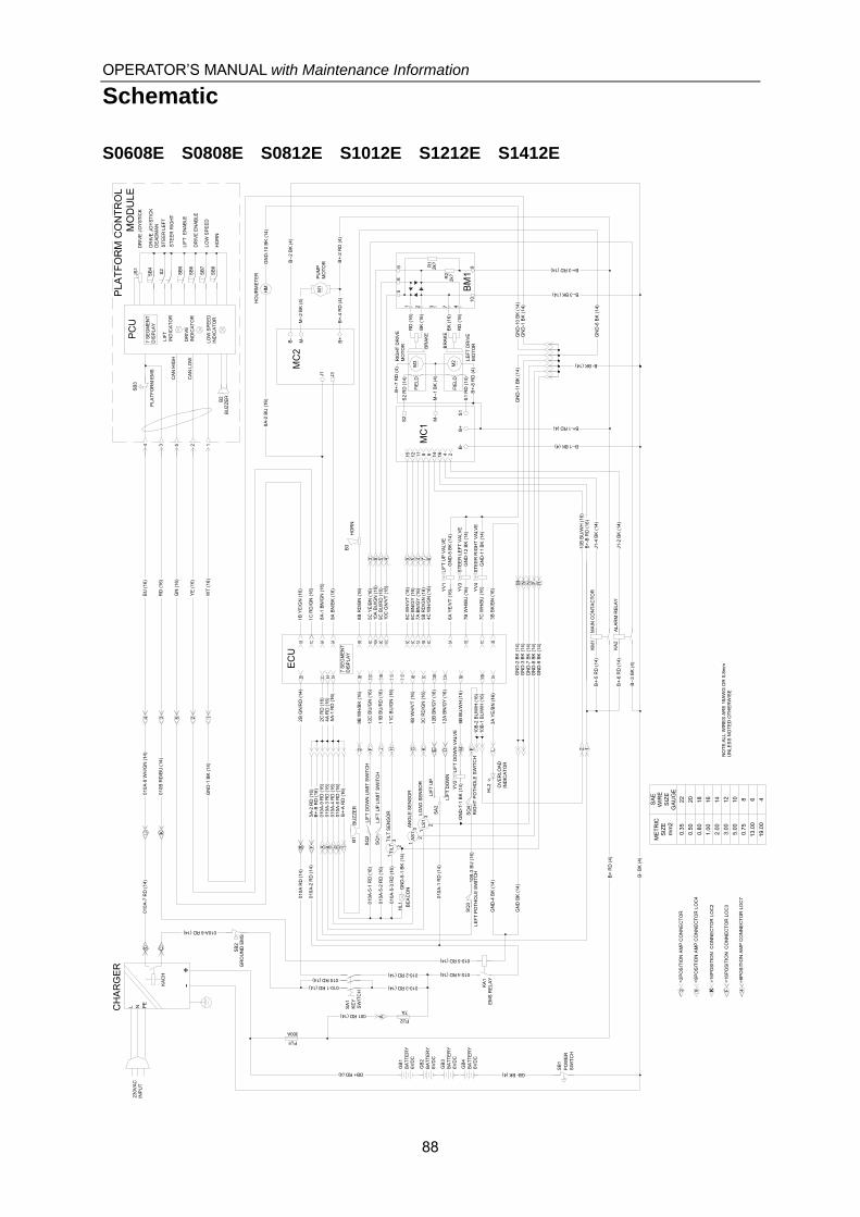
OPERATOR’S MANUAL with Maintenance Information
Schematic
88
S0608E S0808E S0812E S1012E S1212E S1412E
B- BK (14)
ME
TR
ICS
IZE
mm
2
SA
EW
IRE
SIZ
EG
AU
GE
0.35
22
0.50
20
0.80
18
1.00
16
2.00
14
3.00
12
5.00
10
0.75
8
13.0
06
19.0
04
NO
TE
:AL
L W
IRE
S A
RE
18
AW
G O
R 0
.8m
mU
NL
ES
S N
OT
ED
OT
HE
RW
ISE
BE
AC
ON
FU1
300A
L N PE
+-
CH
AR
GE
R
23
0VA
CIN
PU
T
KA
CH
SA
1K
EY
SW
ITC
H
FU2
7A
HL1
BA
TT
ER
Y6
VD
C
GB
3
BA
TT
ER
Y6
VD
C
GB
4
010A-6 RD (14)
010-3 RD (14)
BA
TT
ER
Y6
VD
C
GB
2
BA
TT
ER
Y6
VD
C
GB
1
SB
2G
RO
UN
D E
MS
SB
1
PO
WE
RS
WIT
CH
EC
U
BU
(1
6)
RD
(1
6)
WT
(1
6)
GN
(1
6)
YE
(1
6)
4 15 23
SB
3
PLA
TF
OR
M E
MS
LIF
TIN
DIC
AT
OR
LO
W S
PE
ED
IND
ICA
TO
R
PC
U
DR
IVE
IND
ICA
TO
R
SB
4D
RIV
E J
OY
ST
ICK
DE
AD
MA
N
DR
IVE
JO
YS
TIC
K
S2
ST
EE
R L
EF
T
ST
EE
R R
IGH
T
SB
8
SB
7
SB
6
SB
5
B2
BU
ZZ
ER
LIF
T E
NA
BLE
DR
IVE
EN
AB
LE
LO
W S
PE
ED
HO
RN
JS1
KA
1E
MS
RE
LA
Y
TIL
T
LS1
LO
AD
SE
NS
OR
TIL
T S
EN
SO
R
SQ
1
SQ
2
LIF
T U
P L
IMIT
SW
ITC
H
LIF
T D
OW
N L
IMIT
SW
ITC
H
AS
1A
NG
LE S
EN
SO
R
SA
2L
IFT
UP
LIF
T D
OW
N
B1
BU
ZZ
ER
LE
FT
PO
TH
OL
E S
WIT
CH
SQ
3S
Q4
LIF
T U
P V
ALV
EY
V1
ST
EE
R L
EF
T V
ALV
EY
V3
ST
EE
R R
IGH
T V
ALV
EY
V4
B3
HO
RN
MC
2
M1
PU
MP
MO
TO
R
HM
HO
UR
ME
TE
R
7 S
EG
ME
NT
DIS
PL
AY
4A
RD
(16
)2
C R
D (
16)
1C
RD
/GN
(1
6)
1B
YE
/GN
(16
)
5A
-1 R
D (
16)
9B
WH
/BK
(16
)
12
B B
N/G
Y (
16)
12
A B
N/G
Y (
16)
11
B B
U/R
D (
16)
12
C B
U/G
N (
16)
10B
-1 B
U/W
H (
16)
11
C B
U/G
N (
16)
3C
RD
/GN
(16
)
4B
WH
/VT
(16
)
01
0A
-9 R
D (
16)
01
0A
-3 R
D (
16)
01
0A
-4 R
D (
16)
01
0A
-5 R
D (
16)
5A
-2 R
D (
16)
B+
-B R
D (
16)
B+
-A R
D (
16)
=16
PO
SIT
ION
CO
NN
EC
TO
R L
OC
3
=6P
OS
ITIO
N A
MP
CO
NN
EC
TO
R L
OC
7
=16
PO
SIT
ION
C
ON
NE
CT
OR
LO
C2
=9P
OS
ITIO
N A
MP
CO
NN
EC
TO
R L
OC
4
=2P
OS
ITIO
N A
MP
CO
NN
EC
TO
R
F A B C D
001 RD (14)
A
010-2 RD (14) 010-4 RD (14)
010-1 RD (14)
010 RD (14)
010
A R
D (
14)
B2
B G
N/R
D (
14)
CS4
010
A-7
RD
(14
)J
3 5 2 1
01
0A
-8 W
H/G
N (
14)
GN
D-1
BK
(1
4)
010-5 RD (14)
010
A-2
RD
(14
)
GN
D B
K (
14)
GN
D-2
BK
(1
4)G
ND
-3 B
K (
14)
NM
2
1
010
A-1
RD
(14
)DEH G KF J
K
E1
0B-2
BU
/WH
(16
)7
C W
H/B
U (
16)
7B
WH
/BU
(1
6)
6A
YE
/VT
(16
)
GN
D-1
1 B
K (
14)
GN
D-1
2 B
K (
14)
GN
D-5
BK
(14
)
8B
RD
/BN
(1
6)
6B
BU
/WH
(16
)M
YV
2L
IFT
DO
WN
VA
LVE
9A
BN
/BK
(16
)
8A
-1 B
N/G
N (
16)
J1 J3
8A
-2 B
U (
16)
GN
D-1
0 B
K (
14)
MC
1
15 12 11 8 6 14 16 4
LE
FT
DR
IVE
MO
TO
R
M2R
IGH
T D
RIV
EM
OT
OR
M3
BR
AK
E
BR
AK
E
R1
2k?
R2
2k?
BM
1
4C
WH
/GN
(1
6)
5B
RD
/GN
(1
6)7
A B
N/G
Y (
16)
6C
BN
/GY
(1
6)8
C W
H/V
T (
16)
67459
3B
BK
/BN
(16
)
01
0B
RD
/BU
(14
)
10
C G
N/V
T (
16)
9C
BU
/RD
(1
6)1
0A
BU
/GN
(16
)
459
2
3A
YE
/BN
(16
)G
ND
-4 B
K (
14)
L
MA
IN C
ON
TA
CT
OR
KM
1
AL
AR
M R
ELA
YK
A2
J1-4
BK
(14
)
J1-2
BK
(14
)
2
5C
YE
/BN
(16
)3
7 S
EG
ME
NT
DIS
PLA
Y
GN
D-1
BK
(14
)
GN
D-6
BK
(14
)
GN
D-1
0 B
K (
14)
GN
D-1
1 B
K (
14)
GN
D-7
BK
(1
4)G
ND
-8 B
K (
14)
GN
D-9
BK
(1
4)
PLA
TF
OR
M C
ON
TR
OL
MO
DU
LE
B+
RD
(4)
B-
BK
(4)
1
B-
B+
S1
M-
S2
B+
M-
B-
HL
2 OV
ER
LO
AD
IND
ICA
TO
R
B+-1 RD (4)
B--1 BK (4)
B--
2 B
K (
4)
CA
N H
IGH
CA
N L
OW
B+-3 RD (14)
B--3 BK (14)
2 F 4K9 K
B+
-8 R
D (
4)
B+
-7 R
D (
4)
GB- BK (4)
RD
(1
6)
BK
(16
)
RD
(1
6)
BK
(1
6)
B+
-B R
D (
16)
M--
2 B
K (
4)
B+
-4 R
D (
4)
GB+ RD (4)
10
B B
U/W
H (
16)
010
A-5
-1 R
D (
16)
010
A-5
-2 R
D (
16)
01
0A-5
-3 R
D (
16)
GN
D-9
-1 B
K (
14)
N P R
B--
3 B
K (
4)
GN
D-7
-1 B
K (
14)
RIG
HT
PO
TH
OLE
SW
ITC
H1
0B-3
BU
(1
6)
B+
-2 R
D (
4)
B+
-6 R
D (
14)
B+
-5 R
D (
14)
S2
RD
(14
)
S1
RD
(14
)
68
5
1 2 7 4
109
M--
1 B
K (
4)
13
2
1
13
32
2
FIE
LD
FIE
LD
3

OPERATOR’S MANUAL with Maintenance Information
Inspection and Repair Log
89
Inspection and Repair Log
Date Comments