self-organizing flow technology - in viktor schauberger's footsteps
TRANSCRIPT
Self-organizing Flow Technology
� in Viktor Schauberger�s Footsteps
Lars Johansson Morten Ovesen
Curt Hallberg
Institute of Ecological TechnologyInstitute of Ecological TechnologyInstitute of Ecological TechnologyInstitute of Ecological Technology Scientific and Technical Reports � 1
Malmö - Sweden - 2002


Self-organizing Flow Technology
� in Viktor Schauberger's Footsteps
Lars Johansson
Morten Ovesen
Curt Hallberg
Institute of Ecological TechnologyMalmö, 2002

Self-organizing Flow Technology � in Viktor Schauberger's Footsteps
Lars Johansson, Morten Ovesen, Curt Hallberg
ISBN 91-631-2611-7
Institute of Ecological Technology
Scienti�c and Technical Reports, No. 1
ISSN 1651-4629
Ordering address:
Institute of Ecological Technology
Krokegatan 4
S - 413 18 Göteborg
Sweden
Email: [email protected]
Web: www.iet-community.org
Printed with Computer Modern Roman 11pt, and typeset with LATEX
Institute of Ecological Technology
Malmö, 2002
Preface
This report, originally published in 1997 in Swedish, is here available in English translationfor the �rst time.
During the years since this report was �rst published we have met interest in and gainedrenewed understanding into processes and perspectives that could be characterized asViktor Schauberger's.
As the report now exists in its second edition, we have kept the text much as it wasoriginally written. Some passages that were unclear we have tried to clarify and elucidate,and some errors and typos have been corrected, but mainly the text stands as it wasoriginally written.
We are happy that the renewed activity at the Institute of Ecological Technology hasmade it possible to publish the report at the institute.
A special thanks to Olof Alexandersson for his kind assistance and for having paved theway for the scienti�c study of the ideas and inventions of Viktor Schauberger.
We would also like to give a special thanks to the Department of Limnology at LundUniversity who furnished us with (some of their old) equipment for this project.
Thank you all of you who have supported us over the years, and who have made thisproject possible.
Malmö, May 2002
Lars JohanssonCurt HallbergMorten Ovesen
i

ii

Contents
Summary v
1 Introduction 1
1.1 Viktor Schauberger . . . . . . . . . . . . . . . . . . . . . . . . . . . . . . . 2
1.2 Knossos water supply . . . . . . . . . . . . . . . . . . . . . . . . . . . . . . 3
1.3 The Stuttgart experiments . . . . . . . . . . . . . . . . . . . . . . . . . . . 4
1.4 A new perspective . . . . . . . . . . . . . . . . . . . . . . . . . . . . . . . 5
2 The Stuttgart experiments 7
2.1 Experiments with a rectangular vessel . . . . . . . . . . . . . . . . . . . . 7
2.2 Experiments with a trumpet shaped vessel . . . . . . . . . . . . . . . . . . 9
3 Modelling Tools 11
3.1 The particle perspective . . . . . . . . . . . . . . . . . . . . . . . . . . . . 12
3.2 The vessel perspective � a self-organizing perspective . . . . . . . . . . . 14
3.3 Free and forced vortices . . . . . . . . . . . . . . . . . . . . . . . . . . . . 15
3.3.1 The axial velocity, Vz, and reverse �ow. . . . . . . . . . . . . . . . 16
3.3.2 The tangential velocity, V�, and its importance . . . . . . . . . . . 18
3.4 Flow image modelling . . . . . . . . . . . . . . . . . . . . . . . . . . . . . 20
3.4.1 The handkerchief dynamics . . . . . . . . . . . . . . . . . . . . . . 20
3.4.2 Chaotic pulsation in the vortex . . . . . . . . . . . . . . . . . . . . 22
3.4.3 Bifurcations . . . . . . . . . . . . . . . . . . . . . . . . . . . . . . . 22
4 Oxygenation and ion precipitation 25
4.1 The principle of the Plane pump . . . . . . . . . . . . . . . . . . . . . . . 25
4.1.1 Experimental set-up . . . . . . . . . . . . . . . . . . . . . . . . . . 26
4.1.2 Subpressures and equilibria . . . . . . . . . . . . . . . . . . . . . . 27
iii

CONTENTS
4.2 Oxygenation of water . . . . . . . . . . . . . . . . . . . . . . . . . . . . . . 29
4.3 Ion-precipitation . . . . . . . . . . . . . . . . . . . . . . . . . . . . . . . . 31
5 Separation 33
5.1 Hydrocyclone technology . . . . . . . . . . . . . . . . . . . . . . . . . . . . 33
5.1.1 Estimating separation properties . . . . . . . . . . . . . . . . . . . 33
5.2 The principle of self-organizing separation . . . . . . . . . . . . . . . . . . 34
5.3 Separation with an egg-shaped inlet vessel . . . . . . . . . . . . . . . . . . 36
5.3.1 Separation of pieces of thread . . . . . . . . . . . . . . . . . . . . . 38
5.4 Self-organizing separation in a barrel . . . . . . . . . . . . . . . . . . . . . 39
5.4.1 Separation of suspended materials . . . . . . . . . . . . . . . . . . 39
5.4.2 Removal of oil from water surfaces . . . . . . . . . . . . . . . . . . 39
6 Applications 41
6.1 Treatment of drinking water . . . . . . . . . . . . . . . . . . . . . . . . . . 41
6.2 Treatment of industrial process water . . . . . . . . . . . . . . . . . . . . . 41
6.3 Treatment of sewage water . . . . . . . . . . . . . . . . . . . . . . . . . . . 42
6.4 Restoration of ponds and water courses . . . . . . . . . . . . . . . . . . . 42
6.4.1 Oxygenation of ponds and minor lakes . . . . . . . . . . . . . . . . 42
6.4.2 River regulation and restoration . . . . . . . . . . . . . . . . . . . . 44
Bibliography 47
iv

Summary
In this report we have tried to establish a language assisting the understanding of theideas of the Austrian naturalist Viktor Schauberger, with the aid of concepts from modernresearch into chaotic and self-organizing systems.
We have replicated some of the experiments Schauberger and Pöpel performed in Stuttgartin 1952, relating to vortex generation and particle separation.
From this point of view we have tried to create an overview of existing research in thearea. We have more speci�cally studied the principles governing particle separation andoxygenation, and made a sketch of how these views can be used for water engineeringmore aligned to nature.
The focus of the research has been on modelling. With the aid of concepts like self-organization, free and forced vortex �ow, chaotic pulsation, mathematical bifurcationsand minimal surfaces, and with �ow images like �handkerchief dynamics� and �toroidalvortex �ow� we have tried to sketch a natural sciences perspective that comes close toSchauberger's.
Several technological applications based on this perspective exists, e.g. within watertreatment and watercourse restoration.
An important application is oxygenation of water, in e.g. �sh ponds, bathing facilities,and biological ponds at sewage plants. By letting a vortex funnel with air be pulled downto a specially designed suction pump, air will be injected in the form of very �ne bubbles.This technology could be used at sewage plants in stead of the present �otation method- where air is pressed into the water at the bottom at high pressure, which normallyconsumes a lot of energy. With the same principle at a somewhat greater scale it couldbe possible to restore the level of oxygen in waterways, lakes or minor bays at sea.
The possibilities exists for treating industrial process water, e.g. by separating particlesand oxygenate the water to create an aerobic bacterial fauna in the water, which canthen be reused or recycled. This would have applications in laundry plants, in the foodindustry, and in paper-mill industry, where water consumption is high. Another possibleapplication could be to �trap� oil belts �oating on the sea into a vortex funnel where theoil then could be separated.
Further research could look at upscaled versions of watercourse restoration or at the e�ectson (and possible separation of) ions in water, e.g. for drinking water. Here applicationsinteresting for the third world can be imagined.
CONTENTS
vi
Chapter 1
Introduction
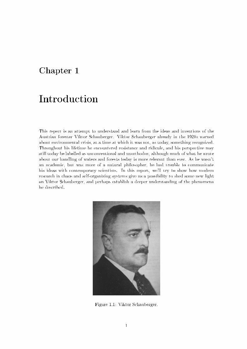
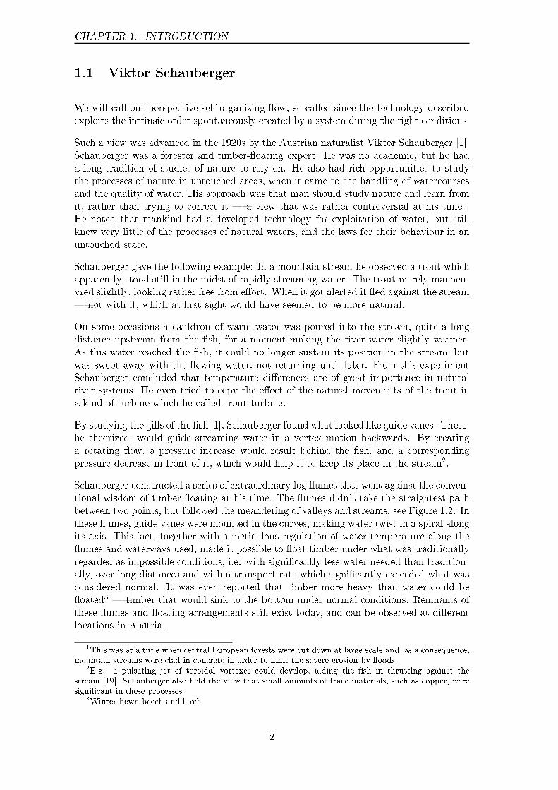
This report is an attempt to understand and learn from the ideas and inventions of theAustrian forester Viktor Schauberger. Viktor Schauberger already in the 1920s warnedabout environmental crisis, at a time at which it was not, as today, something recognized.Throughout his lifetime he encountered resistance and ridicule, and his perspective maystill today be labelled as unconventional and unorthodox, although much of what he wroteabout our handling of waters and forests today is more relevant than ever. As he wasn'tan academic, but was more of a natural philosopher, he had trouble to communicatehis ideas with contemporary scientists. In this report, we'll try to show how modernresearch in chaos and self-organizing systems give us a possibility to shed some new lighton Viktor Schauberger, and perhaps establish a deeper understanding of the phenomenahe described.
Figure 1.1: Viktor Schauberger.
1
CHAPTER 1. INTRODUCTION
1.1 Viktor Schauberger
We will call our perspective self-organizing �ow, so called since the technology describedexploits the intrinsic order spontaneously created by a system during the right conditions.
Such a view was advanced in the 1920s by the Austrian naturalist Viktor Schauberger [1].Schauberger was a forester and timber-�oating expert. He was no academic, but he hada long tradition of studies of nature to rely on. He also had rich opportunities to studythe processes of nature in untouched areas, when it came to the handling of watercoursesand the quality of water. His approach was that man should study nature and learn fromit, rather than trying to correct it � a view that was rather controversial at his time1.He noted that mankind had a developed technology for exploitation of water, but stillknew very little of the processes of natural waters, and the laws for their behaviour in anuntouched state.
Schauberger gave the following example: In a mountain stream he observed a trout whichapparently stood still in the midst of rapidly streaming water. The trout merely manoeu-vred slightly, looking rather free from e�ort. When it got alerted it �ed against the stream� not with it, which at �rst sight would have seemed to be more natural.
On some occasions a cauldron of warm water was poured into the stream, quite a longdistance upstream from the �sh, for a moment making the river water slightly warmer.As this water reached the �sh, it could no longer sustain its position in the stream, butwas swept away with the �owing water, not returning until later. From this experimentSchauberger concluded that temperature di�erences are of great importance in naturalriver systems. He even tried to copy the e�ect of the natural movements of the trout ina kind of turbine which he called trout turbine.
By studying the gills of the �sh [1], Schauberger found what looked like guide vanes. These,he theorized, would guide streaming water in a vortex motion backwards. By creatinga rotating �ow, a pressure increase would result behind the �sh, and a correspondingpressure decrease in front of it, which would help it to keep its place in the stream2.
Schauberger constructed a series of extraordinary log �umes that went against the conven-tional wisdom of timber �oating at his time. The �umes didn't take the straightest pathbetween two points, but followed the meandering of valleys and streams, see Figure 1.2. Inthese �umes, guide vanes were mounted in the curves, making water twist in a spiral alongits axis. This fact, together with a meticulous regulation of water temperature along the�umes and waterways used, made it possible to �oat timber under what was traditionallyregarded as impossible conditions, i.e. with signi�cantly less water needed than tradition-ally, over long distances and with a transport rate which signi�cantly exceeded what wasconsidered normal. It was even reported that timber more heavy than water could be�oated3 � timber that would sink to the bottom under normal conditions. Remnants ofthese �umes and �oating arrangements still exist today, and can be observed at di�erentlocations in Austria.
1This was at a time when central European forests were cut down at large scale and, as a consequence,mountain streams were clad in concrete in order to limit the severe erosion by �oods.
2E.g. a pulsating jet of toroidal vortexes could develop, aiding the �sh in thrusting against thestream [19]. Schauberger also held the view that small amounts of trace materials, such as copper, weresigni�cant in these processes.
3Winter hewn beech and larch.
2

1.2. KNOSSOS WATER SUPPLY
Figure 1.2: One of Schauberger's log �umes. Note the egg-formed section, and how the�ume meanders like a stream. The Krampen-Neuberg �ume in Austria, 1930s.
1.2 Knossos water supply
It is interesting that a water supply technology that displays some similar characteristicscan be found on Crete, at the remnants of the ancient Minoan culture.
Figure 1.3: Some of the conical water pipes at Knossos. From the western part of thepalace, close to the grain silos.
Early in the 20th century, Arthur Evans discovered and restored the palace of Knossos,situated at Kefala hill at the centre of Crete. The oldest parts stem from around 2100-2000 BC. On the walls vortexes and spiralling patterns abound � one wall drawing e.g.shows a Kármán vortex street � displaying that swirling water inspired the inhabitantsof the place [11]. Water certainly was central in Minoan mythology � and treated assomething sacred.
The water supply system is especially interesting. Conical pipes made of terra-cotta,where the narrow opening of each pipe section sticks well into the wide opening of the
3
CHAPTER 1. INTRODUCTION
next section were used, see Figure 1.3. Apart from making it easy to lay out the pipesin a curved fashion, the tapered shape of each section would give the water a shootingmotion4, which would have assisted in preventing the accumulation of sediments. As notedby Evans [11], this would make them more advanced than nearly all modern systems ofearthenware pipes, which have parallel sides. One stretch of pipes even showed an upwardslope, indicating that Minoan engineers were well aware of the fact that water �nds itsown level. In some channels for water, braking vanes, to brake the water at the outercurves can be seen [2].
1.3 The Stuttgart experiments
This report is based on the experiments made by Viktor Schauberger and Prof. FranzPöpel at the Institute of Technology in Stuttgart in 1952 [31]. One of the objectives ofthese experiments was to investigate the possibility of using di�erent kinds of pipes withrotating water, in order to separate the water phase from a suspension of hydrophobicmaterial.
The underlying idea was to use a vessel connected to a straight pipe from below. Waterwas injected tangentially and was allowed to swirl down into the pipe. A vortex wouldappear, and particles in the swirling �ow would accumulate at the centre of the vortex,where the pressure was the least. With suitably designed pipes it was then possible toseparate the hydrophobic material.
The importance of the design of the inlet vessel was also studied. By using a rectangularand a round vessel, two rather di�erent cases could be studied. Not only straight pipeswere used, but also conical and spiralling pipes were used. Pipes made of di�erent mate-rials, such as glass and copper, were studied as well. The experiments were extended intoinvestigating the frictional losses of di�erent pipes and materials.
The results were rather astonishing. Schauberger and Pöpel observed that the frictionalresistance decreased the more conical and spiralling the pipes were made. Pipes made ofcopper had a lower �ow resistance than pipes made of glass. The spiralling copper pipeproduced an undulating friction curve as the �ow was increased. At some �ows a negativefriction was observed, as if water seemed to lose contact with the walls and fall freelythrough the pipe. How to interpret this remains to be seen.
An underlying principle of the Stuttgart experiments is the rotation of water around itsown axis, while it is �owing along a spiralling path with decreasing radius. The rotationalvelocity increases towards the centre where a sub-pressure exists.
Let us study a �bath tub vortex� to illustrate this. With a slow enough �ow, water �owsmore or less straight down into the pipe. But at a critical �ow a transition takes place, abifurcation, and water starts to swirl in a vortex.
In order to make water organize itself into this kind of �ow, we only have to create theright conditions, which in turn will generate the spontaneous emergence of a subpressureaxis. This could be arranged by using a suitable geometry of the vessels, or by introducingdi�erent kinds of guide vanes, pressure sinks etc. (More generally, we have to look at thesystem and its interaction with its surroundings as a whole.) The system then is in a stateof dynamic equilibrium, where it is always changing but where its structure is yet stable.
4By giving the peripheral water a vaulting toroidal �ow.
4
1.4. A NEW PERSPECTIVE
1.4 A new perspective
This is a perspective that is very similar to that of Viktor Schauberger's way of reasoning.He early observed that untouched watercourses had a kind of structural stability. Fromthose observations he suggested methods for river regulation � based on the perspectiveof giving water impulses for self-organization to take place. By using suitable guide vanesand by taking into account the e�ect of the surrounding vegetation on water �ow andtemperature, he could make a watercourse self-organize into a stable river bed.
This way of regulating rivers and watercourses di�ers from the traditional ways, whichtries to steer the �ow and which disregards the 'eco-system' that the �owing water and itsinteraction with the river bed and vegetation makes up � with �oods and bank erosionas the natural result. Schauberger e.g. noted that the sediment transport capacity ofthe �ow a�ected sand and bank development, which a�ected vegetation, which in turna�ected the �ow image of the water, through among other things the vegetation's coolinge�ect. The system bites itself in the tail, as it were.
A problem has been to interpret the language of Schauberger, as it was more that of anaturalist than of a hydrologist. He more looked at the wholeness of the system, thanto its detailed composition, and focused on its �ow image, without knowing or modellingthe underlying mechanisms.
Such a perspective does not look for as detailed a model as possible, but for the simplestmodel that has the same kind of fundamental properties as the system. It is a perspectivethat is close to that of modern chaos science. It has shown that disparate and seeminglycomplex behaviours often can be captured by (ridiculously) simple models5. This is dueto the fact that dynamical behaviours at e.g. phase transitions are universal, and appearsin a wide range of systems [14, 43].
This is the perspective we will bring with us, as we in this report reinterpret and re-examine parts of the Stuttgart experiments and some of the possible applications. Wewill replicate some of these experiments, and from this try to evolve useful models, whichcan help to bridge the perspective of Viktor Schauberger with that of the modern naturalsciences. This leads naturally to some of the main applications � water treatment andrestoration of watercourses. We will take a closer look at these in this report.
5Consider by contrast the complexity of a traditional approach at modelling a highly non-linear systemsuch as free surface �ow with an air funnel.
5

CHAPTER 1. INTRODUCTION
6

Chapter 2
The Stuttgart experiments
In this chapter we will study the experiments performed by Schauberger and Pöpel at theInstitute of Technology in Stuttgart in 1952 [31]. The purpose of these experiments wereto investigate vortex �ow in pipes. A lot of the experiments were devised to study thedevelopment of friction, especially in twisted, spiralling pipes. These experiments havebeen replicated by Kullberg [17], with positive results. In order to get a more thoroughunderstanding of the phenomena and �ow images present, we replicated those of theexperiments that were relevant for separation technology: the study of vortex generationand particle concentration.
Figure 2.1: Schematic drawing of the experimental setups. Rectangular and trumpetshaped vessels respectively.
2.1 Experiments with a rectangular vessel
At the �rst experiment a rectangular vessel was used, where water slowly would well forthacross an edge, see Figure 2.1 and 2.2, in order not to stimulate vortex formation. All
7

CHAPTER 2. THE STUTTGART EXPERIMENTS
vortex generation thus was self-organizing (see the chapter on modelling).
Figure 2.2: The rectangular vessel.
The �ow was kept reasonably slow, 0.2�0.4 l/s. A weak vortex generation could beobserved. The �ow would organize as a spiralling space curve along the pipe. A threadthat was hanging from the inlet was sucked into the pressure minimum, and formed a curvewith increasing wavelength and decreasing amplitude along the tube, see Figure 2.3. Theair bubbles that appeared in the tube would behave similarly. Kullberg observed in hisexperiments that the isobars for the static pressure across sections of the tube formedegg-shaped curves.
Figure 2.3: The spiralling space curve � here visualized with the aid of a thread andbubbles of air.
8

2.2. EXPERIMENTS WITH A TRUMPET SHAPED VESSEL
2.2 Experiments with a trumpet shaped vessel
The rectangular vessel was replaced by a trumpet shaped vessel with tangential inlets,see Figure 2.4. This of course stimulated vortex generation. The shape of the vessel andthe arrangement of water injection were essential for this. The water �ow was the sameas in the previous experiment, 0.2�0.4 l/s.
Figure 2.4: The trumpet shaped vessel. Here the strong vortex generation can be seen.
A stronger vortex generation could be observed. Particles (co�ee), that were spread onthe surface or injected in the form of a suspension, were sucked towards the centre justas the thread. This leads to the question if it would be possible to use the technology toseparate or concentrate suspended materials.
Figure 2.5: The experimental set-up, as seen from the side. In the middle of the pipe astring of co�ee-particles can be glimpsed.
We will in the following try to visualize what is going on in the experiments, and see howthis can be related to Schauberger's view of water.
9

CHAPTER 2. THE STUTTGART EXPERIMENTS
10
Chapter 3
Modelling Tools
In this chapter we will try to de�ne some theoretical tools and models that can be usefulfor addressing problems with self-organizing �ow, or more generally, for focusing on thedynamics of �owing systems rather than on their composition. In this respect, our pointof view will be closer to that of chaos and complexity research than to traditional �uiddynamics. A common feature of both chaos and complexity research is to focus on thebehaviour of a system and on patterns that appear, rather than the detailed compositionof the system [14, 43]. This view is also very close to Schauberger's own, whose languagewas more that of a natural philosopher than of a �uid engineer.
We will begin rather close to traditional theory, by investigating the forces acting on asuspended particle. This is of course relevant for separation. Then we will study somegeneral principles of self-organization, and especially vortex �ow patterns, which will playan important role later on. In the section on �ow modelling we will discuss how �ow canbe modelled without knowing much of the mechanisms involved, with bifurcations andchaotic dynamics being treated more super�cially.
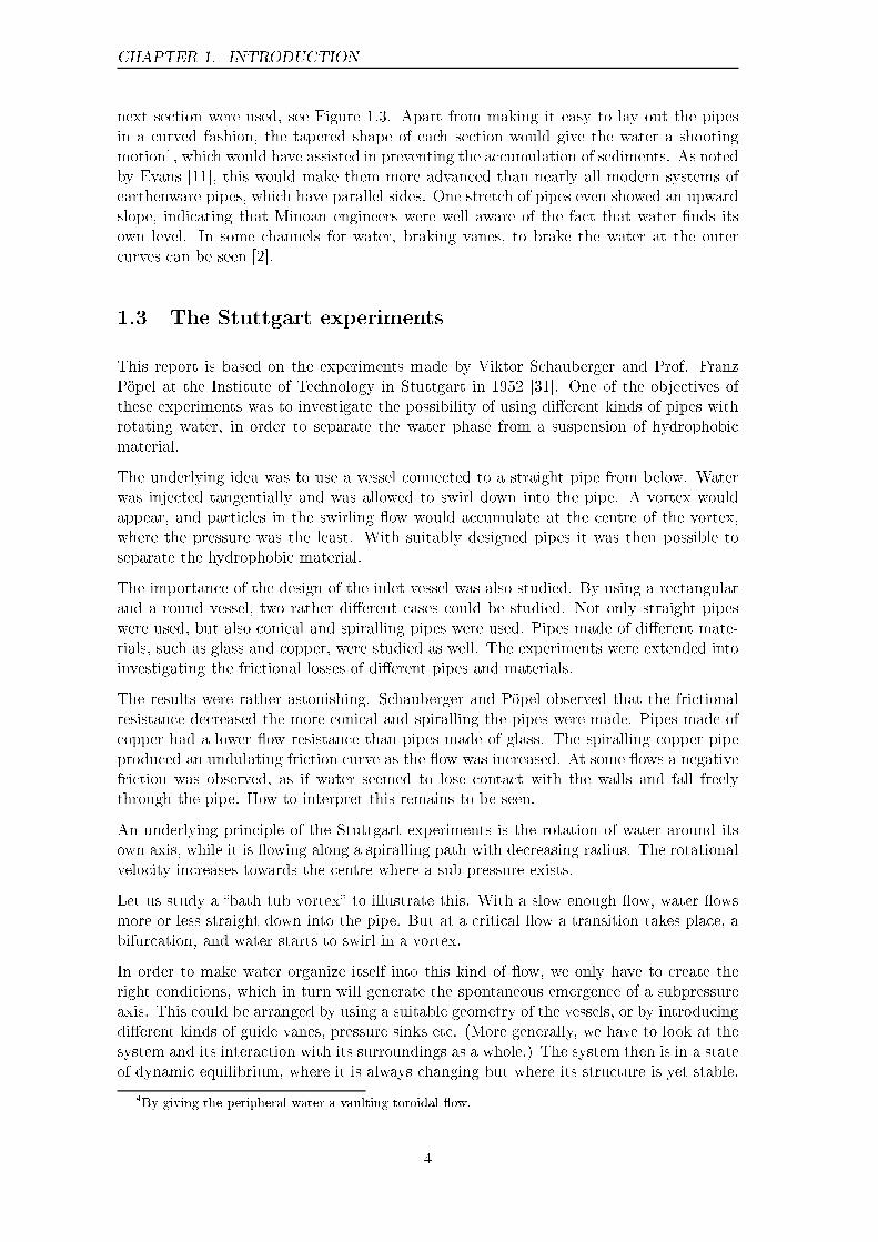
As examples of �owing systems we'll study two systems � a Stuttgart experiment resem-bling set-up, �the egg-tube�, and a barrel with swirling water at the centre, �the barrel�,see Figure 3.1.
Figure 3.1: Two geometries, the egg-tube and the barrel.
In the egg-tube a strong vortex �ow is induced by a series of tangential inlets. The swirling
11
CHAPTER 3. MODELLING TOOLS
water then continues down the pipe and gradually disappears out of the system � theprinciple behind the Stuttgart experiments.
In the barrel a swirling �ow is created by sucking down water at the centre and divertingit towards the sides at the bottom of the vessel � the principle behind a vortex agitatingapparatus like the Aquagyro, see Figure 4.2.
3.1 The particle perspective
Let us study a particle in a medium, e.g. a co�ee particle in water. What forces are actingon the particle? We can discern 4 di�erent kinds of forces.
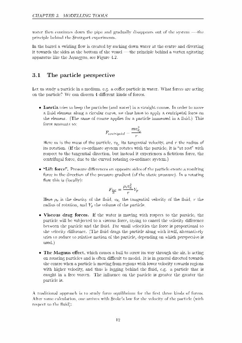
� Inertia tries to keep the particles (and water) in a straight course. In order to movea �uid element along a circular curve, we thus have to apply a centripetal force onthe element. (The same of course applies for a particle immersed in a �uid.) Thisforce amounts to:
Fcentripetal =mv2�p
r
Here m is the mass of the particle, v�p its tangential velocity, and r the radius ofits rotation. (If the co-ordinate system rotates with the particle, it is �at rest� withrespect to the tangential direction, but instead it experiences a �ctitious force, thecentrifugal force, due to the curved rotating co-ordinate system.)
� �Lift force�. Pressure di�erences on opposite sides of the particle create a resultingforce in the direction of the pressure gradient (of the static pressure). In a rotating�ow this is (locally):
F @P@r
=�vv
2
�v
rVp
Here �v is the density of the �uid, v�v the tangential velocity of the �uid, r theradius of rotation, and Vp the volume of the particle.
� Viscous drag forces. If the water is moving with respect to the particle, theparticle will be subjected to a viscous force, trying to cancel the velocity di�erencebetween the particle and the �uid. For small velocities the force is proportional tothe velocity di�erence. (The �uid drags the particle along with itself, alternativelytries to reduce to relative motion of the particle, depending on which perspective isused.)
� The Magnus e�ect, which causes a ball to screw its way through the air, is actingon rotating particles and is often di�cult to model. It is in general directed towardsthe centre when a particle is moving from regions with lower velocity towards regionswith higher velocity, and thus is lagging behind the �uid, e.g. a particle that iscaught in a free vortex. The in�uence on the particle is greater the greater theparticle is.
A traditional approach is to study force equilibrium for the �rst three kinds of forces.After some calculation, one arrives with Stoke's law for the velocity of the particle (withrespect to the �uid):
12

3.1. THE PARTICLE PERSPECTIVE
�vr =v�
2D2(�p � �v)
18�rr̂
Here �vr is the relative velocity of the particle (with respect to the �uid) in the radialdirection, v� the tangential velocity of the �uid, D the diameter of the particle, �p and �vthe densities of the particle and the �uid respectively; r is the distance to the centre ofthe vortex, r̂ the unit vector in the radial direction and � the kinematic viscosity of the�uid.
The above formula involves some approximations, e.g. that the pressure gradient is rea-sonably linear across distances such as a particle diameter, and that the particle doesn'ta�ect the �ow pattern to any great extent, i.e. small particles in dilute �ows. Also, theMagnus e�ect is ignored. For large particles these approximations aren't necessarily validclose to the centre of the vortex, where e.g. the Magnus e�ect will make itself manifest.
Also, it is assumed that the particle moves with the same velocity as the �ow, in thetangential direction. But what happens if the particle is being retarded with respect tothe velocity of the water?
In order to keep a particle in circular motion at a constant radius, we have to apply acentripetal force,
Fcentripetal =mv2�p
r=�pv
2
�p
rVp
where we have introduced �p as the density of the particle, and Vp as its volume.
Since the �uid is rotating, a pressure gradient appears in the radial direction, giving riseto a lift force, which tries to push the particle towards the centre. It is, from above,
F @P@r
=�vv
2
�v
rVp
In order to get a particle to move towards the centre we thus have to have:
F @P@r� Fcentripetal > 0
whence,Vp
r
��vv
2
�v� �pv
2
�p
�> 0
hence, ��vv
2
�v� �pv
2
�p
�> 0
If the particle has the same velocity as the �uid we get (�v��p)v2
�v> 0 , i.e. only particles
that are lighter than the �uid will move towards the centre. If, however, the particle insome way is retarded with respect to the �uid (in the tangential direction), the expressioncan be > 0 despite the fact that �v � �p < 0, i.e. also particles that are heavier than the�uid can be made moving towards the centre.
An example of this is if beads (or tea leaves) rest on the bottom of a barrel (or cup) witha rotating �ow. As long as they are retarded enough by the friction against the bottom,they will be pushed towards the centre (the axis of rotation) and accumulate there.
13
CHAPTER 3. MODELLING TOOLS
3.2 The vessel perspective � a self-organizing perspective
Let us contemplate the water that is swirling in the funnel-like vessel. It then becomesobvious that there are at least 2 distinct ways of generating a vortex �ow:
� External forcing � i.e. the �uid is accelerated from the rim, through the tangen-tial injection of water that strikes into the bulk of water.
� Inner self-organization � by the creation of a subpressure from below, the �uidwill organize itself into a vortex, since conditions for such a self-organization thenappears.
What is actually meant by self-organization? The key point is that we do not have totry to steer water into a speci�c course, e.g. through mechanical mixing, or through aspecially arranged geometry that is diverting the �ow.
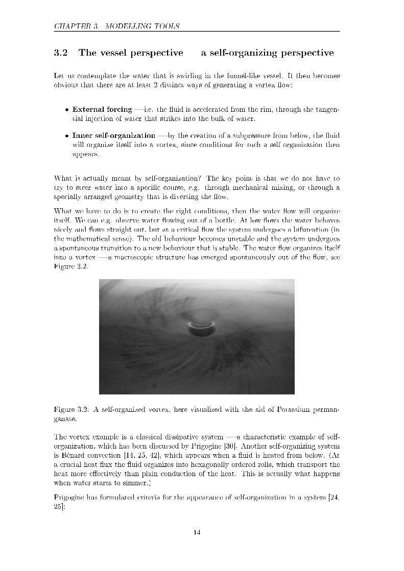
What we have to do is to create the right conditions, then the water �ow will organizeitself. We can e.g. observe water �owing out of a bottle. At low �ows the water behavesnicely and �ows straight out, but at a critical �ow the system undergoes a bifurcation (inthe mathematical sense). The old behaviour becomes unstable and the system undergoesa spontaneous transition to a new behaviour that is stable. The water �ow organizes itselfinto a vortex � a macroscopic structure has emerged spontaneously out of the �ow, seeFigure 3.2.
Figure 3.2: A self-organized vortex, here visualized with the aid of Potassium perman-ganate.
The vortex example is a classical dissipative system � a characteristic example of self-organization, which has been discussed by Prigogine [30]. Another self-organizing systemis Bénard convection [14, 25, 42], which appears when a �uid is heated from below. (Ata crucial heat �ux the �uid organizes into hexagonally ordered rolls, which transport theheat more e�ectively than plain conduction of the heat. This is actually what happenswhen water starts to simmer.)
Prigogine has formulated criteria for the appearance of self-organization in a system [24,25]:
14

3.3. FREE AND FORCED VORTICES
� The system is dissipative � i.e. open and subjected to a �ow which consumesenergy at the macroscopic level.
� The system is far from thermodynamic equilibrium.
� Its parts co-operate in such a way that the system acts as a whole, self-catalytic �e.g. a non-linear system with some positive feedback.
In order to create self-organization in a dissipative system, such as one above, we onlyhave to give the system an impulse, i.e. create the right conditions. Through the posi-tive feedback, �uctuations will be ampli�ed to the macroscopic level � the microscopicmovements have suddenly organized themselves into macroscopic motion.
The system is in a state of dynamic stability, a continuously changing state, yet struc-turally stable. A typical example from atmosphere physics is the red spot of Jupiter, avortex which has remained structurally stable for at least several hundreds of years [14].
In the 20s and 30s, Schauberger observed the structural stability of natural untouchedwater courses � although naturally he didn't use such terms [1, 34]. From his observationshe suggested a way of regulating rivers, based on giving impulses to the water to self-organize into a stable river bed [35, 36, 37]. The principles of this kind of river regulationdi�ers from that of classical ways of regulating rivers, which tries to steer the water intoa certain course � with the associated risks of loosing the river bed stability at increasedwater discharges, with bank erosion and �ooding and as the result.
Figure 3.3: Indirectly acting guide elements, creating the right conditions, which makethe water �ow organize itself into a vortex along the course.
This kind of impulse generation has been studied by Kullberg [17] and Molin/Olsson [22].By placing small guide elements in the main current a subpressure is created, whichself-organizes a vortex along the river course, see Figure 3.3.
Note that we aren't trying to steer the water �ow into a swirling motion. We merelycreate the necessary conditions, then the microscopic �uctuations will be ampli�ed, thestraight �ow become unstable, and make a spontaneous transition into a swirling motionwhich is structurally stable.
3.3 Free and forced vortices
Flows that are circulating around a point can be grouped into two kinds of �ow: quasi-forced and quasi-free vortices [10, 18]. An overview of some kinds of vortices is given inTable 3.1.
15

CHAPTER 3. MODELLING TOOLS
In a forced vortex the water mass is rotating rigidly, like in a centrifuge. With ! = k
we get v� = kr, where v� is the tangential velocity, ! the angular velocity (constant) andr the radius. By de�nition r!(r) = v�(r). The inertial force (the centrifugal force in arotating system) becomes:
F =mv2
r=m!2r2
r= m!2r
and thus increases with increasing radius.
! = v� = Description Fcentripetal =
k kr Rigid rotation, forced vortex. mk2r, increasing withincreasing radius
kr
k An example of a quasi-free vortex. mk2
r, decreasing (with
increasing radius)kr2
kr
Free vortex Potential �ow. Energyper unit of mass constant. Angularmomentum L = v�r constant.
mk2
r3, decreasing (with
increasing radius)
Table 3.1: Properties of free and forced vortices.
A free vortex appears when water is allowed to organize itself, e.g. at an outlet of a vessel,or in a tornado. In a free vortex the angular velocity of the �ow varies with the radius(and increases towards the centre). We get ! = k
r2. This is of course an idealization. A
real vortex often consists of a superposition of a free and a forced vortex, where the outerpart is free, whereas the vortex centre is rotating rigidly, see Figure 3.4.
Figure 3.4: A typical vortex, compounded by a quasi-free and a quasi-forced part.
Let us de�ne some directions of �ow in cylindrical co-ordinates, and investigate closersome of the properties of the �ow in the di�erent directions, see Figure 3.5.
3.3.1 The axial velocity, Vz, and reverse �ow.
We can identify 3 kinds of �ow in the axial direction, which appear in vortex-�ows througha pipe [18], see Figure 3.6.
16
3.3. FREE AND FORCED VORTICES
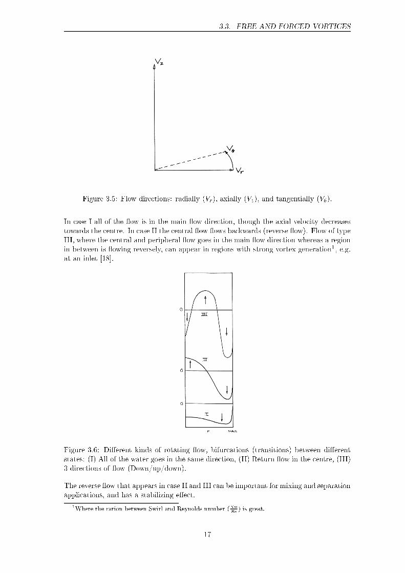
Figure 3.5: Flow directions: radially (Vr), axially (Vz), and tangentially (V�).
In case I all of the �ow is in the main �ow direction, though the axial velocity decreasestowards the centre. In case II the central �ow �ows backwards (reverse �ow). Flow of typeIII, where the central and peripheral �ow goes in the main �ow direction whereas a regionin between is �owing reversely, can appear in regions with strong vortex generation1, e.g.at an inlet [18].
Figure 3.6: Di�erent kinds of rotating �ow, bifurcations (transitions) between di�erentstates: (I) All of the water goes in the same direction, (II) Return �ow in the centre, (III)3 directions of �ow (Down/up/down).
The reverse �ow that appears in case II and III can be important for mixing and separationapplications, and has a stabilizing e�ect.
1Where the ration between Swirl and Reynolds number (SwRe
) is great.
17
CHAPTER 3. MODELLING TOOLS
3.3.2 The tangential velocity, V�, and its importance
The tangential velocity distribution, V�(r), naturally leads to the question of the forcesacting in the radial direction. It is obvious that V�(r) in some way re�ects the forcing ofthe system. Let's have a look at the trumpet shaped vessel. We can imagine several waysof forcing or retarding the system:
� Centripetal forces from the outer form makes the water turn aside.
� Braking vanes at the rim retards the peripheral �ow and thereby indirectly directthe watercourse towards the centre.
� Water is injected tangentially at the periphery and thereby strikes into the mass ofwater and accelerates it.
� A subpressure at the centre tows the water towards the centre.
Thus it is important to get a feeling for what is happening. Let us study these phenomenaone by one.
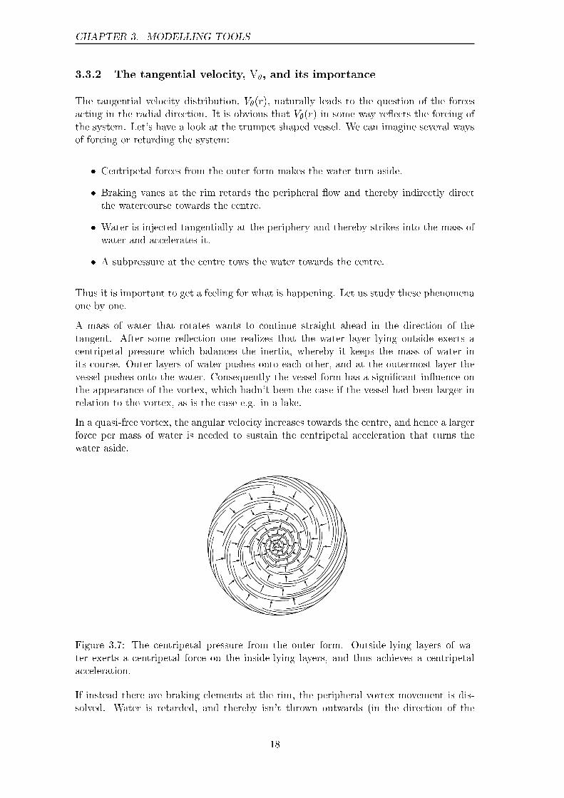
A mass of water that rotates wants to continue straight ahead in the direction of thetangent. After some re�ection one realizes that the water layer lying outside exerts acentripetal pressure which balances the inertia, whereby it keeps the mass of water inits course. Outer layers of water pushes onto each other, and at the outermost layer thevessel pushes onto the water. Consequently the vessel form has a signi�cant in�uence onthe appearance of the vortex, which hadn't been the case if the vessel had been larger inrelation to the vortex, as is the case e.g. in a lake.
In a quasi-free vortex, the angular velocity increases towards the centre, and hence a largerforce per mass of water is needed to sustain the centripetal acceleration that turns thewater aside.
Figure 3.7: The centripetal pressure from the outer form. Outside-lying layers of wa-ter exerts a centripetal force on the inside-lying layers, and thus achieves a centripetalacceleration.
If instead there are braking elements at the rim, the peripheral vortex movement is dis-solved. Water is retarded, and thereby isn't thrown outwards (in the direction of the
18

3.3. FREE AND FORCED VORTICES
tangent) to the same extent, since its momentum has been decreased � thus a smallerforce from the outer form is needed in order to sustain the balance. Schauberger usedthis for river regulation [34], in order to stop the meandering from eroding the river banksmore and more. Imagine how a transient wave towards the periphery thereby is dissolved,and partly re�ected back towards the centre of the stream/river bed.
If water strikes tangentially into the water mass at its periphery, we get a tangentialacceleration there. This will counteract the free vortex generation (where the accelerationis taking part at the centre). If the out�ow at the centre is small, all of the water masswill tend to begin to rotate rigidly.
A central outlet stimulates the emergence of a free vortex, which need a combination oftangential and axial movement. (Of course the movement in some sense is also radial,water is moving towards the centre, but not straight, rather in a quite curved manner.)There we have the necessary subpressure which can self-organize the media.
Let us now study the e�ect of a subpressure in the middle. Does it pull the water (towingit as it were), or does it merely leave room for water that is pushed in from behind?
The point is that the water molecules not only push each other, they also pull each otherdue to the attractive van der Waals forces and hydrogen bonds between the molecules(which e.g. give rise to the viscosity and surface tension of water). If we model a mediumwithout attractive forces as plastic or rubber beads, which are bouncing about, we canimagine water as being rubber beads with rubber bands to the closest neighbours, orsimply rubber beads with small magnets inside. These then will not only leave room forbeads behind as they advance, but will also tow them with themselves.2
Figure 3.8: [A] Plastic beads � an ideal gas or �uidized particles. [B] Beads with smallmagnets inside � a �uid with attractive forces.
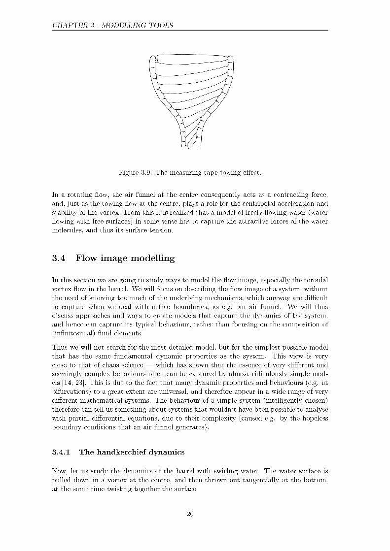
Outer layers thus will be pulled in by inner layers, resembling a structure like a paperor measuring tape that has been rolled up, see Figure 3.9. The outer layers also pushesinwards due to the fact that the outer form (the vessel) exerts a centripetal force. Sincethe circumference decreases towards the centre, the angular velocity has to increase inorder to maintain the �ow, and in order to conserve angular momentum in some sense �the same principle that makes a skating ballerina rotate faster, when she pulls the armstowards the body.
We can note the di�erence between pulling and pushing in a hydrodynamic system. It isespecially clear at an air funnel, which behaves elastically. Whereas it is easy to pull acable (or a rubber band) through a pipe, it is signi�cantly more di�cult to try to push itthrough.
2Also, the beads will try to align their �elds with their neighbours', and thereby spin around, in adynamical changing pattern, at the edge of order and chaos.
19
CHAPTER 3. MODELLING TOOLS
Figure 3.9: The measuring tape towing e�ect.
In a rotating �ow, the air funnel at the centre consequently acts as a contracting force,and, just as the towing �ow at the centre, plays a role for the centripetal acceleration andstability of the vortex. From this it is realized that a model of freely �owing water (water�owing with free surfaces) in some sense has to capture the attractive forces of the watermolecules, and thus its surface tension.
3.4 Flow image modelling
In this section we are going to study ways to model the �ow image, especially the toroidalvortex �ow in the barrel. We will focus on describing the �ow image of a system, withoutthe need of knowing too much of the underlying mechanisms, which anyway are di�cultto capture when we deal with active boundaries, as e.g. an air funnel. We will thusdiscuss approaches and ways to create models that capture the dynamics of the system,and hence can capture its typical behaviour, rather than focusing on the composition of(in�nitesimal) �uid elements.
Thus we will not search for the most detailed model, but for the simplest possible modelthat has the same fundamental dynamic properties as the system. This view is veryclose to that of chaos science � which has shown that the essence of very di�erent andseemingly complex behaviours often can be captured by almost ridiculously simple mod-els [14, 23]. This is due to the fact that many dynamic properties and behaviours (e.g. atbifurcations) to a great extent are universal, and therefore appear in a wide range of verydi�erent mathematical systems. The behaviour of a simple system (intelligently chosen)therefore can tell us something about systems that wouldn't have been possible to analysewith partial di�erential equations, due to their complexity (caused e.g. by the hopelessboundary conditions that an air funnel generates).
3.4.1 The handkerchief dynamics
Now, let us study the dynamics of the barrel with swirling water. The water surface ispulled down in a vortex at the centre, and then thrown out tangentially at the bottom,at the same time twisting together the surface.
20

3.4. FLOW IMAGE MODELLING
Figure 3.10: The handkerchief dynamics: To twist together and stretch.
The process can be likened to pulling a handkerchief through a hole, by seizing it at thecentre, twisting it together, and pulling. The whole procedure can be summarized as:pull, twist and spread. It is obvious that a dynamics of this kind leads to mixing thatin principle is close to that of the classic horseshoe of chaos science � stretch and fold.Points that originally are close to each other will be separated, and �nally loose relationto each other. This of course is of importance for the mixing in the system3.
Figure 3.11: Toroidal vortex �ow.
Once again regard the barrel with the swirling water. After the initiation of the process,the �ow self-organizes into a structure that is stable and swirling. In the barrel a toroidalvortex �ow appears. The �ow is vaulting around a torus, at the same time as it is rotatingfaster towards the centre. This structure resembles so-called twisted scroll rings, whichappear as solutions to a diverse fauna of dynamical systems [28, 44].
3If we could �nd a dynamical system that in its phase space exhibited a similar dynamics, and had asimilar global �ow, we could get some insight into the mixing of the hydrodynamical system by studyingthe mixing in the dynamical system [8, 27].
21
CHAPTER 3. MODELLING TOOLS
3.4.2 Chaotic pulsation in the vortex
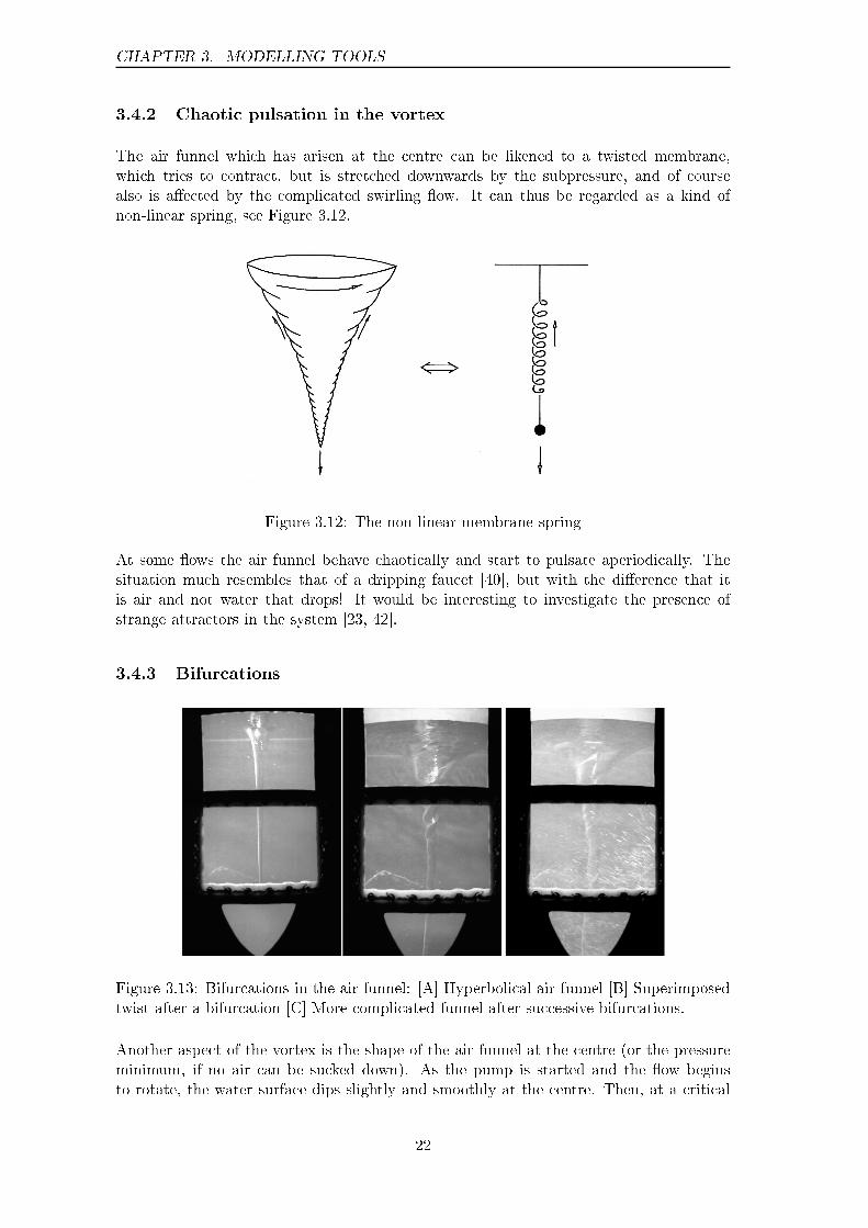
The air funnel which has arisen at the centre can be likened to a twisted membrane,which tries to contract, but is stretched downwards by the subpressure, and of coursealso is a�ected by the complicated swirling �ow. It can thus be regarded as a kind ofnon-linear spring, see Figure 3.12.
Figure 3.12: The non-linear membrane spring
At some �ows the air funnel behave chaotically and start to pulsate aperiodically. Thesituation much resembles that of a dripping faucet [40], but with the di�erence that itis air and not water that drops! It would be interesting to investigate the presence ofstrange attractors in the system [23, 42].
3.4.3 Bifurcations
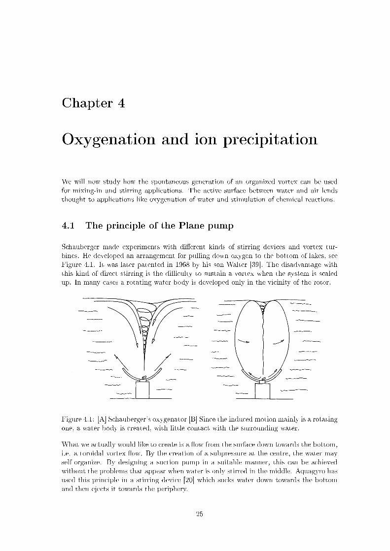
Figure 3.13: Bifurcations in the air funnel: [A] Hyperbolical air funnel [B] Superimposedtwist after a bifurcation [C] More complicated funnel after successive bifurcations.
Another aspect of the vortex is the shape of the air funnel at the centre (or the pressureminimum, if no air can be sucked down). As the pump is started and the �ow beginsto rotate, the water surface dips slightly and smoothly at the centre. Then, at a critical
22

3.4. FLOW IMAGE MODELLING
�ow, a spear-shaped air funnel suddenly appears at the centre, which quickly widens intoa trumpet-shaped form. The air funnel generation can thus be seen as a sudden collapseof one equilibrium state, into another, qualitatively di�erent, equilibrium state.
The air column that appears forms a minimum surface. Surface tension tries to contractthe surface, while the rotating �ow tries to pull it apart. The force balance can be likenedto that in soap bubbles [29], with the di�erence that the inner over-pressure in the soapbubble has been exchanged by inertial forces in the water, which pulls from outside.
From the simple hyperbolic rotation form, the funnel at certain critical �ows undergoes fur-ther bifurcations to more complicated surfaces � one can imagine that a Hopf-bifurcationadds another frequency to the system4. At such a bifurcation the �ow axis/funnel canbegin to twist around its own axis and also form a spiralling (helical) space curve throughthe surrounding medium.
You could think that the twisted shape only is due to the fact that we have a boundarysurface between air and water. What does the �ow at the centre look like, if air isn'tsucked down into it? The �ow, its turns out, still generate spiralling and complex layersof water. Evidently a high degree of macroscopic organization of the �ow exist in thiscase too.
4There are several routes from a stable dynamics to a chaotic �ow [13, 16, 42]. It would be interestingto investigate closer how the bifurcations in the vortex actually occurs.
23

CHAPTER 3. MODELLING TOOLS
24
Chapter 4
Oxygenation and ion precipitation
We will now study how the spontaneous generation of an organized vortex can be usedfor mixing-in and stirring applications. The active surface between water and air lendsthought to applications like oxygenation of water and stimulation of chemical reactions.
4.1 The principle of the Plane pump
Schauberger made experiments with di�erent kinds of stirring devices and vortex tur-bines. He developed an arrangement for pulling down oxygen to the bottom of lakes, seeFigure 4.1. It was later patented in 1968 by his son Walter [39]. The disadvantage withthis kind of direct stirring is the di�culty to sustain a vortex when the system is scaledup. In many cases a rotating water body is developed only in the vicinity of the rotor.
Figure 4.1: [A] Schauberger's oxygenator [B] Since the induced motion mainly is a rotatingone, a water body is created, with little contact with the surrounding water.
What we actually would like to create is a �ow from the surface down towards the bottom,i.e. a toroidal vortex �ow. By the creation of a subpressure at the centre, the water mayself-organize. By designing a suction pump in a suitable manner, this can be achievedwithout the problems that appear when water is only stirred in the middle. Aquagyro hasused this principle in a stirring device [20] which sucks water down towards the bottomand then ejects it towards the periphery.
25

CHAPTER 4. OXYGENATION AND ION PRECIPITATION
Figure 4.2: The principle of the Aquagyro.
It is thus in practice a question of creating a pump that uses the handkerchief dynamics,and then let the water organize itself. Then we get both an e�ective oxygenation andan e�ective mixing, with comparatively little expenditure of energy. This naturally leadsthe mind to the question of how this can be achieved in a simple and practical way. Theplane pump, a centrifugal pump that uses the subpressure in the middle, turns out to bea simple construction capturing the dynamics.
Figure 4.3: The principle of the plane pump. Water is sucked into the pipe in the middleand is thrown out radially towards the periphery.
Two circular plates, joined by radial guiding rims, are brought to rotate. Through a pipein the middle of the upper plate, water is being sucked in and is then ejected towards theperiphery due to the centrifugal force. Since the pipe can be made narrow, a substantialsubpressure can be created. The swirling e�ect in the water is enhanced by the rotationof the plates. The surrounding medium quickly organizes itself to a toroidal vortex �ow.
4.1.1 Experimental set-up
An experiment with a plane pump at the bottom of a great barrel was set up, see Fig-ure 4.4. The barrel, with a diameter of 50 cm, was �lled with water to a height of 80 cm.At the bottom of the barrel the plane pump can be seen, driven by an axis through thebottom. Through the pipe, which makes up the axis, the pressure can be measured. (Inseparation applications, �uid can be extracted out of the central �ow via the axis pipe.)
26

4.1. THE PRINCIPLE OF THE PLANE PUMP
Figure 4.4: A drawing of the experimental set-up.
4.1.2 Subpressures and equilibria
First the �ow behaviour was studied at varying forcing. Already at a low e�ect, 30�40W, the water organized itself into a toroidal vortex �ow. Di�erent kinds of guide vanesin the pump were tested1. Straight vanes turned out to be more e�cient than vanesdirected backwards. Vanes directed forwards2 turned out to be the most e�ective forvortex generation.
First a beautifully trumpet formed hyperbolic surface was created. At a critical angularvelocity (rotation speed) the funnel began to twist, and formed a complicated minimalsurface in a rotating (curved) geometry. At higher rotation speeds the pump started tosqueeze o� air bubbles, with a strong injection of air as a result, see Figure 3.13.
Let us estimate the kinetic energy of the rotating �ow. By analysing the expression forinertial moment, and noting that the rotation in a vortex normally doesn't occur rigidly(i.e. ! isn't constant inside the water body) we arrive with the expression:
Wk =1
2
Z!2r2dm = kmR2!2
R
Here Wk is the kinetic energy, dm an element of mass, ! the angular velocity and r theradius. R is the outer radius (in some sense) of the vortex, and !R the angular velocityof the vortex at this radius. After integration we arrive with an expression similar to theone at the right hand side, with the constant k which depending on the type of �ow.
At rigid rotation of a cylinder we have k = 1
4. For a quasi-free vortex (which we coarsely
approximate to be cylindrical, with !(r) = R!Rr
, we get k = 1
2. For an ideal free vortex,
1Note that the fact that a certain vane curvature makes the pump e�cient to pump water not neces-sarily makes it e�cient to create a swirling �ow in the vessel, as the way the water leaves the pump isalso relevant for this, not just the pumping e�ciency.
2At the periphery.
27
CHAPTER 4. OXYGENATION AND ION PRECIPITATION
!(r) = R2!Rr2
, the integral diverges at the centre. If we note that there is an air columnat the centre, and estimate its radius to approximately R/10, we get k = ln(10) � 2:3.With R = 0:25 m, !R � � rad/s (half a revolution per second) and the amount of waterto 100 litres, this corresponds to energies of approximately 15, 30, and 140 Ws, for rigid,quasi-free, and free vortexes respectively.
The supplied mechanical e�ect (from the pump) is probably signi�cantly less than the70 Watts which are fed to the pump as electrical e�ect at full speed. The e�ciency,through driving band, bearings and friction in the pump, probably is in the range 20�40%, which gives a net e�ect in the range of 15�30 W. If we take into account that itcould take 10�20 seconds for the vortex to develop, we �nd that supplied energy in orderto accelerate the vortex is of the same magnitude as for a free vortex. Of course thecalculation is just a very coarse estimate.
Losses due to the inner friction of water should correspond to the net e�ect the pumpsupplies when the vortex has had time to develop fully. These reasonably should be quitesmall, since the rotation speed of the pump could be reduced signi�cantly (from 10�15revolutions per second to 3�4) with maintained vortex formation.
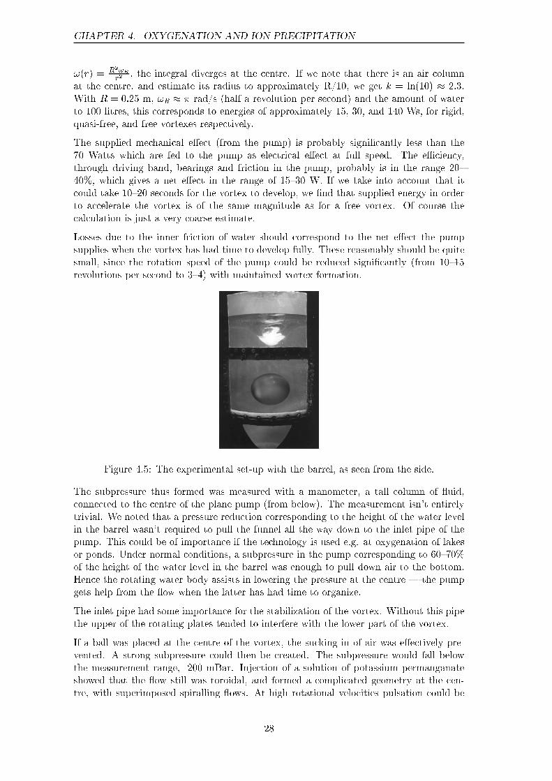
Figure 4.5: The experimental set-up with the barrel, as seen from the side.
The subpressure thus formed was measured with a manometer, a tall column of �uid,connected to the centre of the plane pump (from below). The measurement isn't entirelytrivial. We noted that a pressure reduction corresponding to the height of the water levelin the barrel wasn't required to pull the funnel all the way down to the inlet pipe of thepump. This could be of importance if the technology is used e.g. at oxygenation of lakesor ponds. Under normal conditions, a subpressure in the pump corresponding to 60�70%of the height of the water level in the barrel was enough to pull down air to the bottom.Hence the rotating water body assists in lowering the pressure at the centre � the pumpgets help from the �ow when the latter has had time to organize.
The inlet pipe had some importance for the stabilization of the vortex. Without this pipethe upper of the rotating plates tended to interfere with the lower part of the vortex.
If a ball was placed at the centre of the vortex, the sucking in of air was e�ectively pre-vented. A strong subpressure could then be created. The subpressure would fall belowthe measurement range, -200 mBar. Injection of a solution of potassium permanganateshowed that the �ow still was toroidal, and formed a complicated geometry at the cen-tre, with superimposed spiralling �ows. At high rotational velocities pulsation could be
28

4.2. OXYGENATION OF WATER
observed through the pump3.
Braking vanes placed at the wall could to some extent direct the upper �ow towards thecentre. It was, however, important not to make the vanes too large.
4.2 Oxygenation of water
Now, how could the above be used for oxygenation? We can discern three distinct cases:
� An air funnel is pulled down, and is twisted o� in the pump, leading to a streamof air bubbles being ejected along its periphery as the result. This causes a forcefulbut e�cient oxygenation, suitable for industrial applications.
� A stable air funnel is pulled down towards the pump, acting as an active surface,which facilitates mixing in of air in the water. The surface of the water is, as itwere, moved closer towards the bottom, at the same time as the mixing in increasesdue to the increased circulation. The water is oxygenated in a more peaceful way(which doesn't disturb life at a lake bottom to the same extent).
� Oxygen rich water is pulled down without the development of an air funnel � e.g.with the aid of an inlet-suction vessel.
Figure 4.6: The Repulsator.
Oxygenation at a small scale was investigated in 1988 by Nordell and Nordmark [26].A small Aquagyro stirring device was placed in an egg-shaped vessel (a repulsator) �lledwith water, after which it was started. A stable vortex funnel, which assisted oxygenation,developed. After one hour the water had reached a good level of oxygen saturation.
3One may ask what the �ow image would look like in the pump if only one of the plates would rotate,or with a geometry like that of Schauberger's rill plates [1]. This would lead to a discussion of Taylor-Couette-like �ow between the plates, with the possibility of mode locking of water rolls towards the rillplates in the latter case, but that would fall outside the objective of this report.
29
CHAPTER 4. OXYGENATION AND ION PRECIPITATION
Description Before After Note
Temperature[�C] 22.5 23.2
Concentration of O2 [mg/l] 2.39 8.51 Full oxygen saturation
Table 4.1: Oxygenation in an egg-shaped vessel, �Repulsator�, by Nordell and Nordmark.
At another experiment, made by Aquagyro at Pålträsk water supply in 1990, an increasefrom 0.4 to 10.5 mg/l was observed [6]. It was also noted that the smell of hydrogensulphide (H2S) had been eliminated.
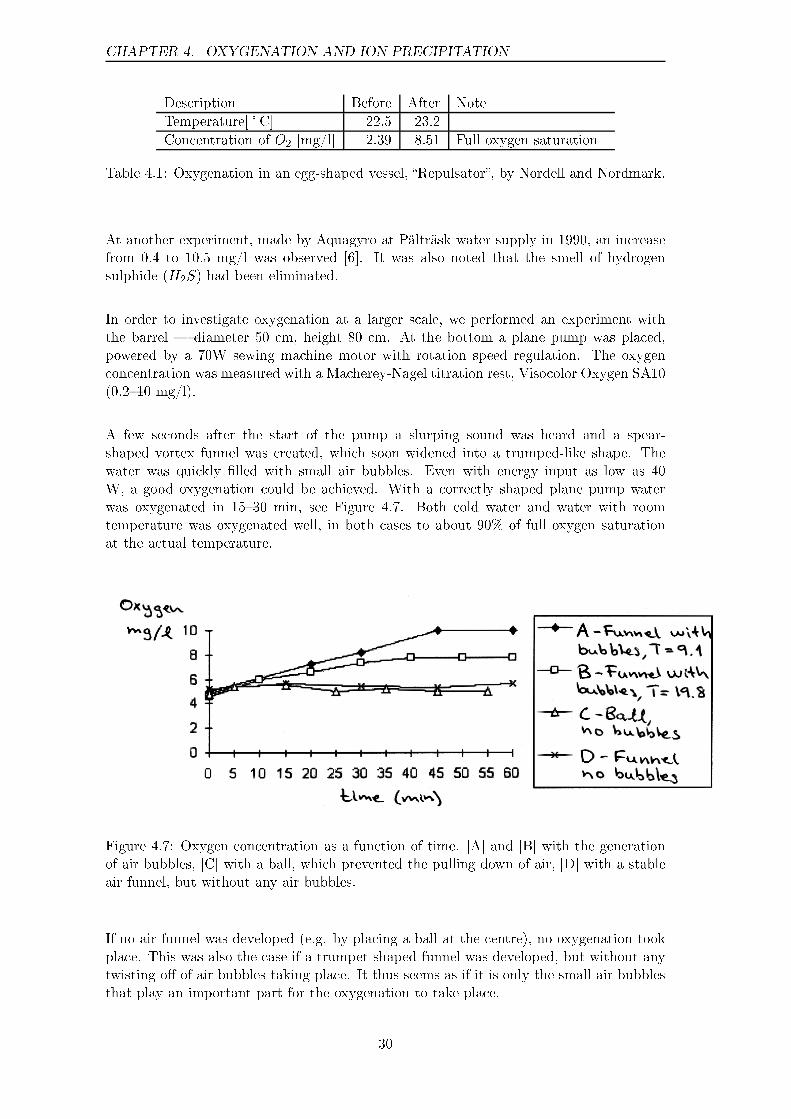
In order to investigate oxygenation at a larger scale, we performed an experiment withthe barrel � diameter 50 cm, height 80 cm. At the bottom a plane pump was placed,powered by a 70W sewing machine motor with rotation speed regulation. The oxygenconcentration was measured with a Macherey-Nagel titration rest, Visocolor Oxygen SA10(0.2�10 mg/l).
A few seconds after the start of the pump a slurping sound was heard and a spear-shaped vortex funnel was created, which soon widened into a trumped-like shape. Thewater was quickly �lled with small air bubbles. Even with energy input as low as 40W, a good oxygenation could be achieved. With a correctly shaped plane pump waterwas oxygenated in 15�30 min, see Figure 4.7. Both cold water and water with roomtemperature was oxygenated well, in both cases to about 90% of full oxygen saturationat the actual temperature.
Figure 4.7: Oxygen concentration as a function of time. [A] and [B] with the generationof air bubbles, [C] with a ball, which prevented the pulling down of air, [D] with a stableair funnel, but without any air bubbles.
If no air funnel was developed (e.g. by placing a ball at the centre), no oxygenation tookplace. This was also the case if a trumpet-shaped funnel was developed, but without anytwisting o� of air bubbles taking place. It thus seems as if it is only the small air bubblesthat play an important part for the oxygenation to take place.
30
4.3. ION-PRECIPITATION
4.3 Ion-precipitation
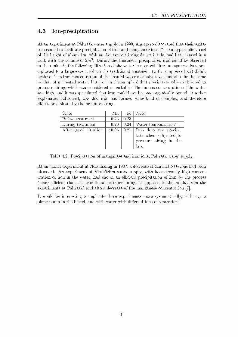
At an experiment at Pålträsk water supply in 1990, Aquagyro discovered that their agita-tor seemed to facilitate precipitation of iron and manganese ions [7]. An hyperbolic vesselof the height of about 1m, with an Aquagyro stirring device inside, had been placed in atank with the volume of 3m3. During the treatment precipitated iron could be observedin the tank. At the following �ltration of the water in a gravel �lter, manganese ions pre-cipitated to a large extent, which the traditional treatment (with compressed air) didn'tachieve. The iron concentration of the treated water at analysis was found to be the sameas that of untreated water, but iron in the sample didn't precipitate when subjected topressure airing, which was considered remarkable. The humus concentration of the waterwas high, and it was speculated that iron could have become organically bound. Anotherexplanation advanced, was that iron had formed some kind of complex, and thereforedidn't precipitate by the pressure airing.
State Mn Fe Note
Before treatment 0.26 0.23
During treatment 0.29 0.24 Water temperature 7�.
After gravel �ltration <0.05 0.21 Iron does not precipi-tate when subjected topressure airing in thelab.
Table 4.2: Precipitation of manganese and iron ions, Pålträsk water supply.
At an earlier experiment at Nordmaling in 1987, a decrease of Mn and NO2 ions had beenobserved. An experiment at Vistbäcken water supply, with its extremely high concen-tration of iron in the water, had shown an e�cient precipitation of iron by the process(more e�cient than the traditional pressure airing, as opposed to the results from theexperiments at Pålträsk) and also a decrease of the manganese concentration [7].
It would be interesting to replicate these experiments more systematically, with e.g. aplane pump in the barrel, and with water with di�erent ion concentrations.
31

CHAPTER 4. OXYGENATION AND ION PRECIPITATION
32
Chapter 5
Separation
In this chapter we will study how a swirling �ow may be used in order to remove particlesand separate �uids of di�erent densities. We'll start by studying existing hydrocyclonetechnology and its function, and then go on to see how the self-organizing �ow that wehave previously discussed may be used for separation applications.
5.1 Hydrocyclone technology
A hydrocyclone is basically made of a conical pipe, see Figure 5.1. Water is injectedtangentially at high pressure (1�3 Bar) in the upper part, which creates a strongly rotating�uid column. The outer layers of the �uid will form a (quasi-) free vortex, whereas themore central parts will rotate rigidly. At the very centre an air column is often created.Due to the variation of the �ow with respect to the radius, light and long particles willmove towards the centre more than the heavier and rounder ones. By letting water ata certain radius being separated at the lower part of the hydrocyclone, the �reject� �ow,and by letting the central �ow leave at the upper part, the �accept� �ow, a separation ofparticles (especially heavy ones) is obtained.
Hydrocyclone technology has proven useful for pulp industry (separation of sand andsticks) [15, 12], for separation at mining industry [41], and for treatment of runo� waterat car washes [33]. Usually the separation is done by several steps.
Small hydrocyclones tend to have a better separation performance than larger ones. Smallthreads, however, tend to create problems by clogging the reject opening, e.g. in textileindustry applications. Power consumption tend to be some kilowatts for a hydrocycloneon the length 1 m.
5.1.1 Estimating separation properties
In the hydrocyclone, the separation performance depend on which particles move towardsthe centre, or central �ow. How could separation properties be estimated numerically?One way is to simulate di�erent particle trajectories and make statistical estimates. Inpractice, however, this may be very di�cult to carry out.
When it comes to real applications, what is of interest is to estimate size and otherproperties of particles which take the accept or reject path. Often a boundary layer
33

CHAPTER 5. SEPARATION
Figure 5.1: The principle of a hydrocyclone.
exists in the �ow, where particles of the right size stand still in the �ow � in the sensethat they neither move towards the accept or reject exits. This becomes more obviousby considering a rotating �ow � it is possible to imagine a particle keeping a constantradius, neither moving towards the periphery nor the centre. Many simulation approachestherefore focus on determining equilibrium sizes of the particles, i.e. particles that willget stuck in a boundary layer [9].
To focus on a particle tends to miss the global �ow, but is of course a good way of obtainingseparation characteristics when the �ow image is rather simple, as in the hydrocyclone.At the applications with self-organizing �ow that we have discussed, the �ow has morefreedom, and is therefore more di�cult to estimate numerically. We will therefore choosea more empirical approach.
5.2 The principle of self-organizing separation
Now let us for a moment re�ect upon the �ow image in the Stuttgart experiment. Couldit be developed into a separation technology that qualitatively di�ers from hydrocyclonetechnology? At the Stuttgart experiment suspended materials accumulated at the centre.Two questions naturally arise:
� Where in the pipe does the concentration of materials towards the centre occur, andwhat factors a�ect the tendency to accumulate them?
� How could the central string of particles be separated without disturbing the �ow?
It can be shown that the free vortex region is important for the centring e�ect on parti-cles [9]. In such a region an e�ect similar to that which occurs when a particle lags thewater �ow takes place � a pressure gradient pushes the particle towards the centre. Even
34
5.2. THE PRINCIPLE OF SELF-ORGANIZING SEPARATION
heavy particles can be pushed towards the centre, at least transiently, until they haveachieved enough tangential velocity to be thrown outwards again.
Consequently we need an acceleration of the rotation speed towards the centre, togetherwith a discharge of the �ow (e.g. in the axial direction) in order to get an e�ectiveseparation. If the inlet vessel is made too large, the whole water mass will tend to rotatealmost rigidly in the peripheral region. This leads to a reduced centralization of particles,and thus a less e�ective separation.
There are several ways of solving this issue:
� The inlet vessel is made narrower, which better directs the formation of the vortex.
� The injection is adjusted, so that it improves the conditions for the emergence of afree vortex region.
� Braking vanes are introduced, which dissolve the sti� rotation at the periphery, andthus force water to organize towards the centre. In practice this adjusts the injectionand makes the vessel look smaller to the �ow.
� The form and proportions of the vessel are adapted to stimulate the right kind ofvortex generation along a longer part of the vessel.
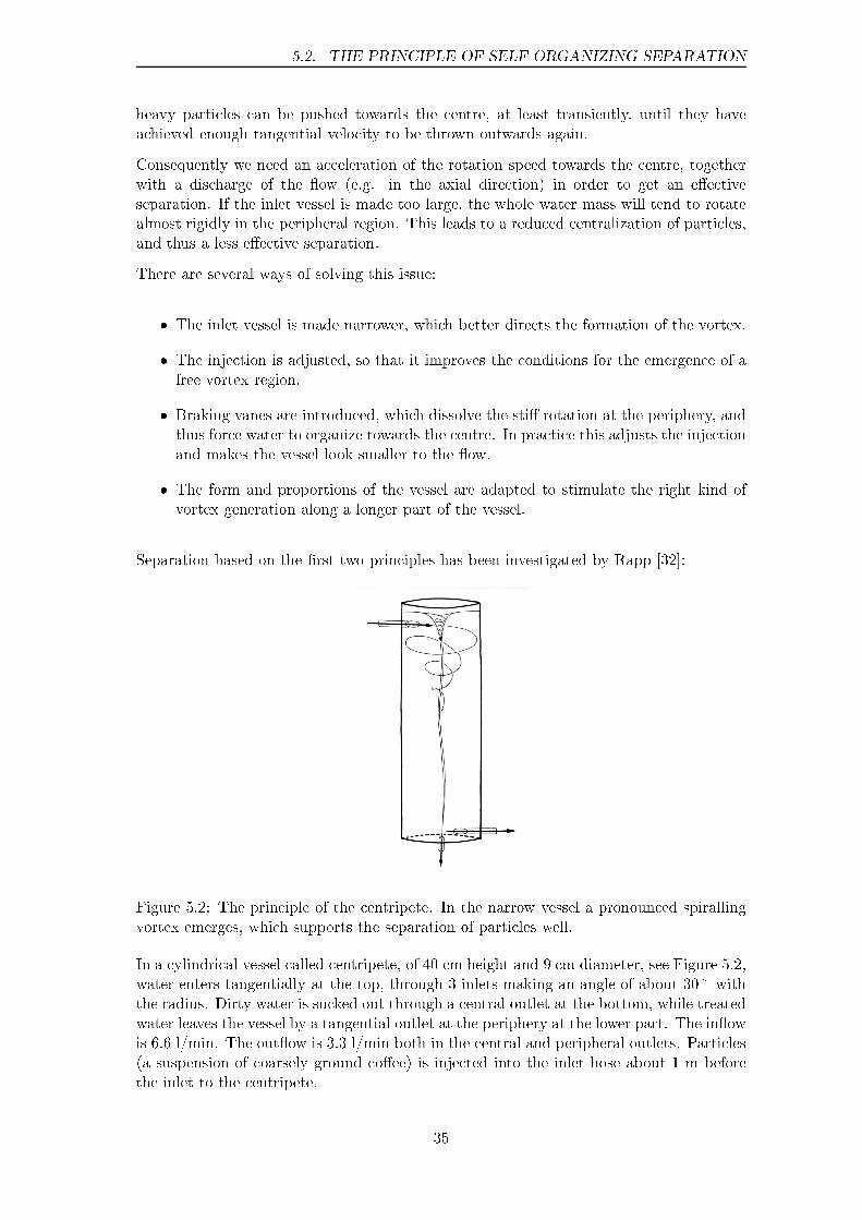
Separation based on the �rst two principles has been investigated by Rapp [32]:
Figure 5.2: The principle of the centripete. In the narrow vessel a pronounced spirallingvortex emerges, which supports the separation of particles well.
In a cylindrical vessel called centripete, of 40 cm height and 9 cm diameter, see Figure 5.2,water enters tangentially at the top, through 3 inlets making an angle of about 30� withthe radius. Dirty water is sucked out through a central outlet at the bottom, while treatedwater leaves the vessel by a tangential outlet at the periphery at the lower part. The in�owis 6.6 l/min. The out�ow is 3.3 l/min both in the central and peripheral outlets. Particles(a suspension of coarsely ground co�ee) is injected into the inlet hose about 1 m beforethe inlet to the centripete.
35

CHAPTER 5. SEPARATION
Rapp found that 93�96% of the particles could be collected through the central outlet. Itwas furthermore observed that heavy particles (used co�ee particles, that had been boiledwith water) in principle wasn't separated at all � they even tended to go in the peripheraloutlet (42�50% of those particles went in the central outlet). It thus seems essential thatthe density of the particles is about that of water.
If a radial outlet was used, somewhat less (91%) of the particle phase was separated. Thiscould be due to the fact that a radial outlet disturbs the vortex, see below. A tangentialvortex more easily supports the swirling motion at the lower part of the vessel.
5.3 Separation with an egg-shaped inlet vessel
In order to investigate self-organizing separation we performed the following experiment:
Figure 5.3: Stuttgart experiment set-up with an egg-shaped inlet vessel.
The inlet of the Stuttgart experiment set-up was replaced by a more narrow and egg-shaped one, with the water injection arranged in such a way as to support vortex gener-ation, see Figure 5.3. Suspended material, which was injected, tended to be accumulatedat the centre of the tube. In the upper part of the tube a rotating �ow with Vz directedupwards was observed, i.e. a �ow of type II. This meant that materials which were caughtat the centre weren't �ushed downwards with the �ow, but stayed in the upper part ofthe tube � a toroidal vortex �ow, stretched in the vertical direction. About 1.5 m belowthe inlet vessel the �ow changed from type II to type I, i.e. the rotation had decreasedin relation to the axial motion, to such an extent that Vz was directed downwards acrossthe whole section of the tube in that region.
The quasi-free vortex �ow means that surfaces swirl around each other, faster and fastertowards the centre. Since also the axial velocity Vz varies with the radius, the particlesin the vessel follow complicated screw-shaped trajectories, see Figure 5.4.
In order to separate the particles which accumulate at the centre (as a central string), anarrow pipe, �i = 4 mm, was introduced, and connected to a vessel with a subpressure.A tap opened and closed the connection to the subpressure vessel.
36

5.3. SEPARATION WITH AN EGG-SHAPED INLET VESSEL
Figure 5.4: Flows within �ows. Here surfaces of water swirl around each other. Theparticles describe a screw-shaped dance.
A sharply bent outlet for the peripheral �ow turned out to disturb the �ow too much. Byarranging a smoother transition, a more stable vortex �ow was achieved also in the lowerpart of the tube. The �ow through the thick peripheral tube was about 0.6 l/s. (Whenthe tap was opened a small fraction of this would go through the central outlet instead.)
A suspension of water and coarse-ground co�ee was poured into the over�ow vessel, whichsurrounded the egg-shaped inlet vessel, and mixed quickly with the in�owing water. As itwas �owing down into the tube, the material would concentrate along the vortex centre.
Figure 5.5: The undulating and spiralling central �ow has locked together with the centraloutlet � co�ee particles which have accumulated at the centre are removed from the restof the �ow.
When the subpressure was connected to the narrow pipe, the central string of co�ee lockedonto the central outlet, and hence it could be separated e�ectively, see Figure 5.5. Whencoarse-ground co�ee (�boiling co�ee�) was used, � � 0.5�1.5 mm, most of it somewhat
37

CHAPTER 5. SEPARATION
lighter than water, more than 90% of the co�ee phase was separated together with anamount of water which was a fraction (a few per cent) of the �ow through the large tube.Fine-ground co�ee (�percolation co�ee�), which is made of smaller, � � 0.2�0.5 mm, andheavier particles (60�70% of the phase heavier than water), were separated signi�cantlyless well.
Figure 5.6: The upper and lower pressure minima are locked together.
Two things turned out to be important in order to achieve a successful separation:
� To make the tapering of the tube for the peripheral �ow smooth, to avoid disturbingthe rotating �ow.
� That the pressure minimum generated by the inlet vortex is relatively well de�nedat the outlet, making possible for the pressure minimum at the central separationoutlet to lock together with it.
The latter in particular means that the tube mustn't be too long. The ratio betweentangential and axial �ow (swirl) is also important. At times when the upper pressureminimum was ill de�ned at the lower part, a temporary lock-on could be observed. Thelower part of the vortex funnel � which is more like a thread � then behaved like a rubberstring that is stretched (but along a curved line!) and then suddenly released. This rubberband dynamics is due to the fact that the vortex centre (the pressure minimum) behavesas an elastic and twisted membrane � a non-linear membrane spring.
5.3.1 Separation of pieces of thread
Experiments with separation of pieces of thread were successful. Pieces of sewing thread,7�14 cm long, mixed up with water was very e�ectively separated � more or less allof the pieces made it to the central outlet. Even tangled pieces were separated well.Long particles (e.g. rootlets or small twigs) should not be present, since the pieces ofthread would wind themselves around them, and clog the outlet. Pure thread suspensionshowever, showed no signs of choking up.
38
5.4. SELF-ORGANIZING SEPARATION IN A BARREL
5.4 Self-organizing separation in a barrel
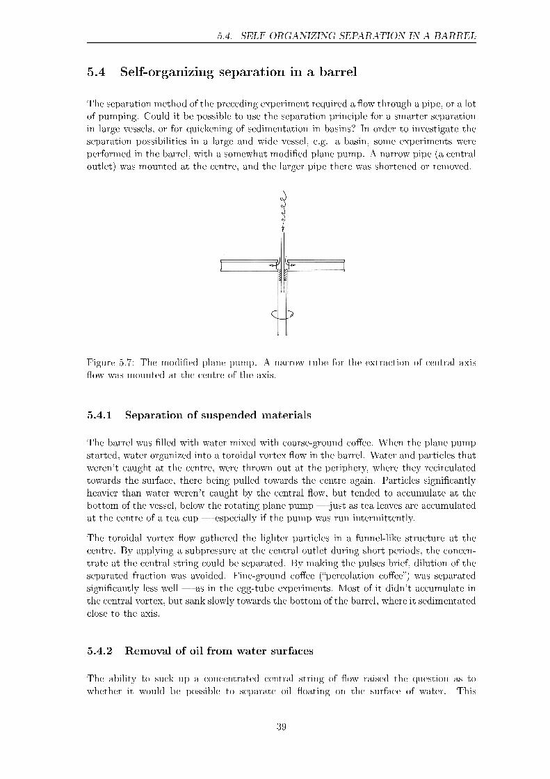
The separation method of the preceding experiment required a �ow through a pipe, or a lotof pumping. Could it be possible to use the separation principle for a smarter separationin large vessels, or for quickening of sedimentation in basins? In order to investigate theseparation possibilities in a large and wide vessel, e.g. a basin, some experiments wereperformed in the barrel, with a somewhat modi�ed plane pump. A narrow pipe (a centraloutlet) was mounted at the centre, and the larger pipe there was shortened or removed.
Figure 5.7: The modi�ed plane pump. A narrow tube for the extraction of central axis�ow was mounted at the centre of the axis.
5.4.1 Separation of suspended materials
The barrel was �lled with water mixed with coarse-ground co�ee. When the plane pumpstarted, water organized into a toroidal vortex �ow in the barrel. Water and particles thatweren't caught at the centre, were thrown out at the periphery, where they recirculatedtowards the surface, there being pulled towards the centre again. Particles signi�cantlyheavier than water weren't caught by the central �ow, but tended to accumulate at thebottom of the vessel, below the rotating plane pump � just as tea leaves are accumulatedat the centre of a tea cup � especially if the pump was run intermittently.
The toroidal vortex �ow gathered the lighter particles in a funnel-like structure at thecentre. By applying a subpressure at the central outlet during short periods, the concen-trate at the central string could be separated. By making the pulses brief, dilution of theseparated fraction was avoided. Fine-ground co�ee (�percolation co�ee�) was separatedsigni�cantly less well � as in the egg-tube experiments. Most of it didn't accumulate inthe central vortex, but sank slowly towards the bottom of the barrel, where it sedimentatedclose to the axis.
5.4.2 Removal of oil from water surfaces
The ability to suck up a concentrated central string of �ow raised the question as towhether it would be possible to separate oil �oating on the surface of water. This
39
CHAPTER 5. SEPARATION
would lead to applications such as oil sani�cation, something that had been advancedby Aquagyro [20].
In order to investigate this more closely, 200 ml of oil (rapeseed oil) was poured out ontothe water surface in the barrel, after which the plane pump carefully was started. About30% of the oil accumulated at the centre, and formed a quite aesthetic yellow funnel,which could be separated. If the �ow was made more violent, the �uid became opaquedue to suspension of oil in the water. This happened if the �ow was made forceful enoughto throw out air bubbles. Only oil �oating on the surface could be separated. Hence avery careful �ow is needed in order to collect oil, which can be extracted by a small pumpthat sucks up the oil funnel from above.
40
Chapter 6
Applications
We will now try to outline some applications of self organizing �ow technology. We willalso discuss possibilities of scaling up the technology in di�erent ways.
6.1 Treatment of drinking water
The experiments with oxygenation shows that the technology can be used for oxygenationof water and consequently for �airing� of bad smell, e.g. from hydrogen sulphide. Ions ofiron and manganese are likely to precipitate e�ectively. This means that the technologyhas potential applications at drinking water treatment, and implies possibilities to reducedependence on chemicals at metal ion separation. Oxygenation of aquaria is anotherapplication � this brings the additional advantage of e�ective water circulation to theaquarium.
6.2 Treatment of industrial process water
Due to the demand for increasing environmental concerns in industry, the need of closedprocess systems has increased. Closed systems leads to the problem of getting rid ofanaerobic bacteria from the system. Here the e�ective airing previously discussed couldhave important applications. With an e�ective circulation and mixing in of oxygen, aer-obic bacteria (responsible for breakdown of organic tensides) are favoured. This leadsto a state of the water system more resembling that in a natural stream than that of astagnant non-circulating pond.
Another application is at �otation, e�ective mixing in of air bubbles in a �uid, whichnormally is quite energy consuming, since the air bubbles has to overcome the pressure ofthe standing water column during the process. With the plane pump this is solved sinceair is sucked into the pump where it is dispersed. Since the water is �owing toroidally,air bubbles will not rise upwards immediately, but instead drift in the radial direction �thereby being spread e�ectively.
When it comes to separation, the technology have applications especially for the removalof �bres in textile industry.
41
CHAPTER 6. APPLICATIONS
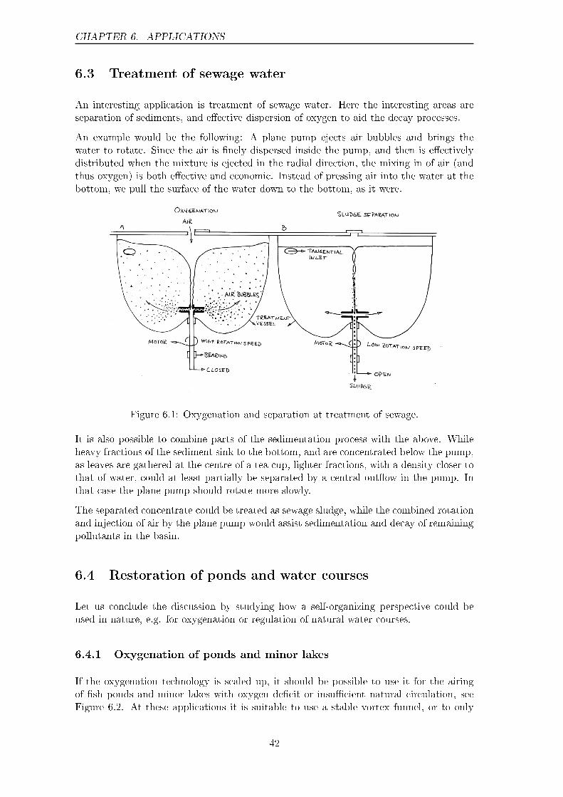
6.3 Treatment of sewage water
An interesting application is treatment of sewage water. Here the interesting areas areseparation of sediments, and e�ective dispersion of oxygen to aid the decay processes.
An example would be the following: A plane pump ejects air bubbles and brings thewater to rotate. Since the air is �nely dispersed inside the pump, and then is e�ectivelydistributed when the mixture is ejected in the radial direction, the mixing in of air (andthus oxygen) is both e�ective and economic. Instead of pressing air into the water at thebottom, we pull the surface of the water down to the bottom, as it were.
Figure 6.1: Oxygenation and separation at treatment of sewage.
It is also possible to combine parts of the sedimentation process with the above. Whileheavy fractions of the sediment sink to the bottom, and are concentrated below the pump,as leaves are gathered at the centre of a tea cup, lighter fractions, with a density closer tothat of water, could at least partially be separated by a central out�ow in the pump. Inthat case the plane pump should rotate more slowly.
The separated concentrate could be treated as sewage sludge, while the combined rotationand injection of air by the plane pump would assist sedimentation and decay of remainingpollutants in the basin.
6.4 Restoration of ponds and water courses
Let us conclude the discussion by studying how a self-organizing perspective could beused in nature, e.g. for oxygenation or regulation of natural water courses.
6.4.1 Oxygenation of ponds and minor lakes
If the oxygenation technology is scaled up, it should be possible to use it for the airingof �sh ponds and minor lakes with oxygen de�cit or insu�cient natural circulation, seeFigure 6.2. At these applications it is suitable to use a stable vortex funnel, or to only
42
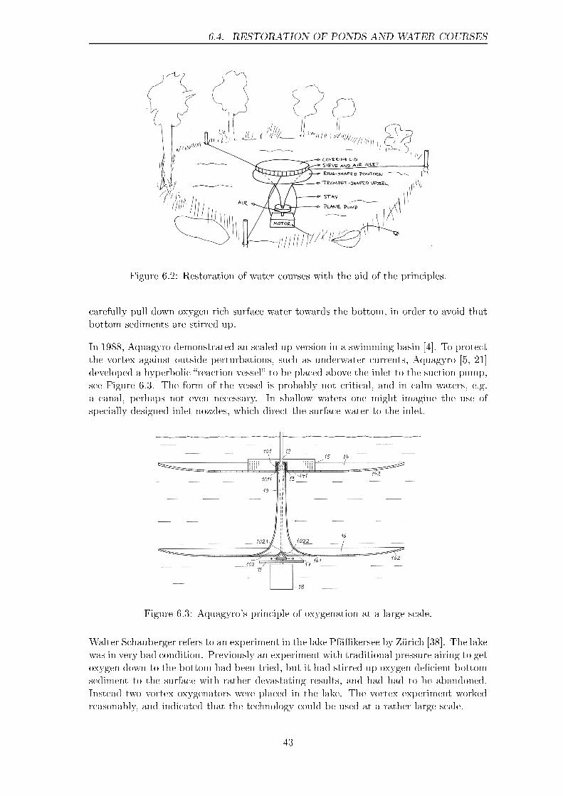
6.4. RESTORATION OF PONDS AND WATER COURSES
Figure 6.2: Restoration of water courses with the aid of the principles.
carefully pull down oxygen rich surface water towards the bottom, in order to avoid thatbottom sediments are stirred up.
In 1988, Aquagyro demonstrated an scaled up version in a swimming basin [4]. To protectthe vortex against outside perturbations, such as underwater currents, Aquagyro [5, 21]developed a hyperbolic �reaction vessel� to be placed above the inlet to the suction pump,see Figure 6.3. The form of the vessel is probably not critical, and in calm waters, e.g.a canal, perhaps not even necessary. In shallow waters one might imagine the use ofspecially designed inlet nozzles, which direct the surface water to the inlet.
Figure 6.3: Aquagyro's principle of oxygenation at a large scale.
Walter Schauberger refers to an experiment in the lake Pfä�kersee by Zürich [38]. The lakewas in very bad condition. Previously an experiment with traditional pressure airing to getoxygen down to the bottom had been tried, but it had stirred up oxygen de�cient bottomsediment to the surface with rather devastating results, and had had to be abandoned.Instead two vortex oxygenators were placed in the lake. The vortex experiment workedreasonably, and indicated that the technology could be used at a rather large scale.
43
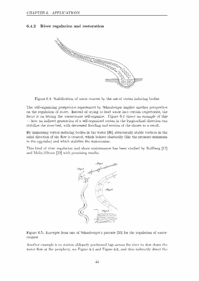
CHAPTER 6. APPLICATIONS
6.4.2 River regulation and restoration
Figure 6.4: Stabilization of water courses by the use of vortex inducing bodies
The self-organizing perspective represented by Schauberger implies another perspectiveon the regulation of rivers. Instead of trying to lead water into certain trajectories, thefocus is on letting the watercourse self-organize. Figure 6.4 shows an example of this� how an indirect generation of a self-organized vortex in the longitudinal direction canstabilize the river-bed, with decreased �ooding and erosion of the shores as a result.
By immersing vortex inducing bodies in the water [36], structurally stable vortices in theaxial direction of the �ow is created, which behave elastically (like the pressure minimumin the egg-tube) and which stabilize the watercourse.
This kind of river regulation and shore maintenance has been studied by Kullberg [17]and Molin/Olsson [22] with promising results.
Figure 6.5: Excerpts from one of Schauberger's patents [35] for the regulation of water-courses
Another example is to station obliquely positioned logs across the river to slow down thewater �ow at the periphery, see Figure 6.5 and Figure 6.6, and thus indirectly direct the
44

6.4. RESTORATION OF PONDS AND WATER COURSES
water towards the inner curve � a principle used by Schauberger for river regulation inAustria [35].
In that way the river-bed is stabilized and shore erosion is decreased, in the way indicatedin Figure 6.5. A rather calm �marshy� region is thereby created at the outer curve. Thefollowing picture, with an example of natural river regulation in the Freinbach stream inAustria, ends the chapter.
Figure 6.6: Displacement of the axis of �ow towards the inner curve, by the use of obliquelypositioned logs, which slows down the �ow at the outer curve. Freinbach in Steiermarkdistrict, Austria.
45
CHAPTER 6. APPLICATIONS
46

Bibliography
[1] Alexandersson, Olof Living water Gateway Books, 1990
[2] Alexandersson, Olof Private communication
[3] Antipov, S.V.; Nezlin, M.V. & Trubnikov, A.S. Rossby Autosoliton JETP Lett, Vol.41, 1985, p. 30-33
[4] Aquagyro AB Ny öppenhet för ekologiskt inriktad teknik Gyroskopet, No. 2, 1989, p.2-6, (Information magazine from Aquagyro AB, Umeå)
[5] Aquagyro AB Storskalig virvelteknik för miljövård inom synhåll Gyroskopet, No. 1,1990, p. 4-5, (Information magazine from Aquagyro AB, Umeå)
[6] Aquagyro AB Demonstrationsanläggning i Älvsbyn � preliminär utvärdering Gy-roskopet, No. 1, 1990, p. 9-13, (Information magazine from Aquagyro AB, Umeå)
[7] Aquagyro AB Pilotanläggning i Älvsbyn Information brochure from Aquagyro AB,Umeå, 1991
[8] Aref, Hassan & Tryggvason, Grétar Vortex Dynamics of passive and active interfacesPhysica D, Vol. 12, 1984, p. 59-70
[9] Bouchillon, Charles W. & Franko, Andrew Computer Modeling Improves the Designof Hydrocyclones for Pulp Cleaning Paper Trade Journal, Vol. 168, 1984, p. 54-56
[10] Coulson, John M. & Richardsson, J.F. Chemical engineering 4:th ed., PergamonPress, Oxford, 1990
[11] Evans, Arthur The Palace of Minos � a comparative account of the successive stagesof the early Cretan civilization as illustrated by the discoveries at Knossos Vol. 1,London, 1921, p. 141-43, 225-230, 371-75 and Vol. 3, London, 1930, p. 233-61
[12] Frykhult, Rune Hydrocyclones � function and development views Report, AB Cel-leco, Stockholm
[13] Gaponov-Grekhov, A.V.; Rabinovich, M.I. & Starobinets, I.M. The Onset and theDevelopment of Chaotic Structures in Dissipative Media in Self-Organization: Au-towaves and structures far from equilibrium, ed. V.I. Krinsky, Springer Verlag, Hei-delberg, 1984, p. 130-38
[14] Gleick, James Chaos � Making a new science Viking Penguin, N.Y., 1987
[15] Gavelin, Gunnar Virvelrenare för �bersuspensioner Kemisk tidskrift, No. 11, 1981
47

BIBLIOGRAPHY
[16] Kats, V.A. & Trubetskov, D.I. Stochastization of Nonstationary Structures in a Dis-tributed Oscillator with Delay in Self-Organization: Autowaves and structures farfrom equilibrium, ed. V.I. Krinsky, Springer Verlag, Heidelberg, 1984, p. 81-86
[17] Kullberg, Sten Vattenströmning i spiralformade och koniska rör � stömningsförsökmed anknytning till Viktor Schaubergers teorier Trita-Kut 3013, Masters Thesis, De-partment of Land Improvement and Drainage, Royal Institue of Technology, Sweden,1982
[18] Kuroda, Chiaki & Ogawa, Kohei Turbulent swirling pipe �ows in Encyclopedia ofFluid Mechanics, Vol. 1 � Flow Phenomena and Measurement, Chapter 20, GulfPublishing Co, Houston, 1986
[19] Lugt, Hans J. Vortex Flow in Nature and Technology John Wiley & Sons, N.Y., 1983
[20] Löfgren, Stefan Omrörningsorgan Swedish Patent No. B 460 706, (8705205-6)
[21] Löfgren, Stefan Anordning för berarbetning av ett rörligt medium Swedish Patent No.C2 500 416, (8903548-9)
[22] Molin, Lena & Olsson, Susanne Sedimenttransport i rinnande vatten � laborato-rieförsök Bachelor Thesis 1989:5, Department of Natural Sciences and Technology,Institute of Technology in Kalmar, Sweden, 1989
[23] Moon, Francis C. Chaotic and Fractal Dynamics � an introduction for Applied Sci-entists and Engineers John Wiley & Sons, NY, 1992
[24] Nicolis, Grégoire & Prigogine, Ilya Self-Organization in Nonequilibrium Systems �From Dissipative Structures to Order through Fluctuations John Wiley & Sons, NY,1977
[25] Nicolis, Grégoire & Prigogine, Ilya Exploring Complexity W.H. Freeman & Co, NY,1989
[26] Nordell, Bo & Nordmark, Desiree Laboratorieförsök med vatten i virvelrörelse � Mät-ning av fysikaliska egenskaper Internal Report 1988:05, Department of EnvironmentalEngineering, Division of Water Resources Engineering, Luleå Institute of Technology,Sweden, 1988
[27] Ottino, Julio M. The kinematics of mixing � stretching, chaos and transport Cam-bridge University Press, Cambridge, 1989
[28] Pan�lov, A.V. & Winfree, A.T. Dynamical simulations of twisted scroll rings in three-dimensional excitable media Physica D, Vol. 17, 1985, p. 323-330
[29] Plateau, J.A.F. Statique Expérimentale et Théorique des Liquides Soumis aux SeulesForces Moléculaires Gauthier-Villars, Paris, 1873
[30] Prigogine, I. & Glansdor�, P. Thermodynamic theory of structures, stabilities and�uctuations Wiley & Sons, London, 1971
[31] Pöpel, Franz Rapport över preliminära undersökningar av spiralrör med olika formInstitute of Ecological Technology, Sweden, 1986. (Originally published as Berichtüber die Voruntersuchnungen mit Wendelrohren mit verschniedener Wandform In-ternal Report, Institut für Gesundheitstechnik, Institute of Technology in Stuttgart,1952. Published in English in The Energy Evolution Viktor Schauberger & CallumCoats (ed.), p. 222-47, Gateway Books, Bath, 2000)
48

BIBLIOGRAPHY
[32] Rapp, Gudmund Separation av ka�ekorn från vatten med cylindercentripet Report2/94 + Appendix, Rapp Kommunikation HB, Saltsjöbaden
[33] Ribea Engineering AB, Information brochure from Ribea Engineering AB, Edsbruk
[34] Schauberger, Viktor Temperatur och vattenrörelse � nya upptäckter om vatten-rörelsens lagbundenhet och anvisningar för en ny teknik inom vattenbyggnad ochskogsvård Institute of Ecological Technology, Sweden, 1983. (Originally publishedas a series of articles in Die Wasserwirtschaft, Wien, 1930-31. Published in Englishin The Water Wizard Viktor Schauberger & Callum Coats (ed.), p. 94-159, GatewayBooks, Bath, 1998)
[35] Schauberger, Viktor Einbau zur Wildbachverbauung und Fluÿregulierung AustrianPatent No. 113487, 1929
[36] Schauberger, Viktor Wasserführung in Rohren und Gerinnen Austrian Patent No.134543, 1933
[37] Schauberger, Viktor Wasserführung Austrian Patent No. 138296, 1934
[38] Schauberger, Walter Vattenrening in Vi måste gå en annan väg, p. 88-91, Alexan-dersson, Olof & Gustavsson Bertil eds., Institute of Ecological Technology, Sweden,1986.
[39] Schauberger, Walter Verfahren und Vorrichtung zur Herstellung von Gemischen, Lö-sungen, Emulsionen, Suspensionen u. dgl. sowie zur biologischen Reinigung von freienGewässern Austrian Patent No. 265991, 1968
[40] Shaw, Robert The Dripping Faucet as a Model Chaotic System The Science FrontierExpress Series, Aerial Press, Santa Cruz, CA, 1984
[41] Tarr, D.T. Practical application of liquid cyclones in mineral dressing problems Re-port, 1965, Krebs Engineers, Palo Alto, CA, USA
[42] Tsonis, Anastasios A. Chaos � From Theory to Applications Plenum Press, NY,1992
[43] Waldrop, M. Mitchell Complexity: The Emerging Science at the Edge of order &Chaos Penguin, 1992
[44] Winfree, A.T. Wavefront geometry in exitable media Physica D, Vol. 12, 1984, p.321-32
49

Lars JohanssonMorten OvesenCurt Hallberg
Self-organizing Flow Technology – in Viktor Schauberger’s Footsteps
This report tries to evolve a new perspective on the ideas of the Austriannaturalist Viktor Schauberger, with the aid of concepts from modernresearch into chaotic and self-organizing systems. The focus of the reportis on modelling. With the aid of concepts like self-organization, free andforced vortex flow, chaotic pulsation, mathematical bifurcations andminimal surfaces, and with flow images like “handkerchief dynamics”and “toroidal vortex flow”, we try to sketch a natural sciences perspectivethat comes close to Schauberger's.
We replicate the Stuttgart experiments with vortex generation andparticle separation, and give an overview of existing research in the area.
The report also covers applications such as oxygenation of water, e.g. infish ponds, bathing facilities, and sewage plants, and particle separation,e.g. in laundry plants, the food industry, and paper-mill industry. Someperspectives are also given on restoration of natural waterways and minorlakes or bays.
Institute of Ecological Technology IET MalmöKrokegatan 4 Lantmannagatan 64S - 413 18 Göteborg S - 214 48 MalmöSweden Sweden
Email: [email protected]: www.iet-community.org
ISBN 91-631-2611-7 – ISSN 1651-4629