self-open damper hinge instruction hg-jhs11
TRANSCRIPT
F1 Additional products for No.240A catalogue(Furniture and Architectural Products) Visit our website for the latest information: https://www.sugatsune-intl.com/
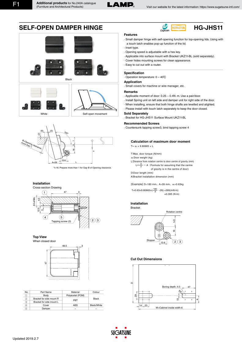
· Applicable moment of door: 0.25 – 0.4N · m. Use a pair/door.· Install Spring unit on left side and damper unit for right side of the door. · When installing, ensure that both hinge shafts are levelled and alighted.· Please install with touch latch separately to keep the door closed.
· Bracket for HG-JHS11 Surface Mount UKZ11-BL
· Countersunk tapping screw3, bind tapping screw 4
Remarks
Sold Separately
Recommended Screws
(6) (3) 105°
B=Opening clearance,
more than 1
*t=16. Prepare more than 1 for Gap B of Opening clearance.
16
(2)
t3
13.6A=26 L
m
48.5 3
47
W=Cabinet inside width-6
R4
23
47
14
A
D
15
29
Boring depth: 4.5
Top View
Cut Out Dimensions
Features· Small damper hinge with self-opening function for top-opening lids. Using with
a touch latch enables pop-up function of the lid.· Inset type.· Opening speed is adjustable with a hex key.· Applicable into surface mount with Bracket UKZ11-BL (sold separately).· Cover hides mounting screws for clean appearance.· Easy to cut out with a router.
Specification
Application· Operation temperature: 0 – 40
· Small covers for machine or wire manager, etc.
No. Part Name Material ColourBody Polyacetal (POM)
BlackBracket for side mount RPBT
Bracket for side mount LCover ABS Black/White
Damper − −
Installation
4.5
8.5
at M
in.
12.5 3
3471
2 34 5
Tapping screw (3)
Rotation centre
Stopper
16t+
3
3213.6
T= m × 9.80665 × L
T:Max. door torque (N/mm)
m:Door weight (kg)
L:Disrance from rotation centre to door centre of gravity (mm)
L= - A(Formula for assuming that the centre
of gravity is in the centre of door)
D:Door length (mm)
A:Bracket installation dimension (mm)
[Example] D=180 mm、A=26 mm、m=0.63kg
T=0.63×9.80665×( −26) =395(mN・m)
=0.395 (N・m)
2D
2180Cross-section Drawing
When closed door
BracketInstallation
Calculation of maximum door moment
White
Black
Self-open movement
SELF-OPEN DAMPER HINGE INSTRUCTION HG-JHS11
Updated 2019.2.7

F2 Additional products for No.240A catalogue(Furniture and Architectural Products) Visit our website for the latest information: https://www.sugatsune-intl.com/
Sold by set.RoHS CAD Item Code Item Name Colour Torque N · m/pair Torque kgf/pair Opening Angle Weight Box Carton− 170-041-214 HG-JHS11-2BL Black
0.1 – 0.25 1.02 – 2.55105° 56 g
12 set 50 set− 170-041-215 HG-JHS11-2WT White 12 set 50 set− 170-041-216 HG-JHS11-4BL Black
0.25 – 0.4 2.55 – 4.0812 set 50 set
− 170-041-217 HG-JHS11-4WT White 12 set 50 set
Body
Adjustment of Lid Opening Speed
Insert a hex key (size 3) into the hole of spring unit (L side)
Push in the hex key *until toothed projection is disengaged, while rotating counter clockwise by 30 °, and then pull it out.
Close the lid, and check if the lid can be opened smoothly. Repeat steps 1 -3 (maximum 5 times) if the lid opening speed is still slow.
Loosen the force following the hex key rotating clockwise.
When increasing lid opening speed
When decreasing lid opening speed (returning to the speed before adjustment)
Insert
*Make sure to rotate counter clockwise following pushing in the hex key and disengaging the projection. Forced rotation may cause damage.
Toothed projection
Fast
Slow
Surface Mount Type(Installed with Bracket for Surface Mount UKZ11-BL)
93
473
Bind taping screw (4)
4.5
8.5
at M
in.
12.5
1
4 5 2
48
2913.6
48.5
18
39
Cross-section Drawing
Top View
No. Part Name Material ColourBody Polyacetal (POM)
BlackBracket for side mount RPBT
Bracket for side mount LCover ABS Black / White
Damper − −
14
3 47 399
23
D
Boring Depth: 4.5
R4
152913.6
13.6
A
W=Cabinet inside width-6
Cut Out Dimensions
t+3
163
13.6
9
Stopper
Rotation Centre
3
Bracket
RoHS CAD Item Code Item Name Colour Weight Box Carton 170-041-218 UKZ11-BL Black 12 g 50 set 500 set
Sold by set.Bracket for Surface Mount
Installation
Updated 2019.2.7

F3 Additional products for No.240A catalogue(Furniture and Architectural Products) Visit our website for the latest information: https://www.sugatsune-intl.com/
Model Torque force Lid size (example)
HG-JHM9-S4(U4) 0.027~ 0.043 N・m(0.275~ 0.44 kgf・cm)
HG-JHM9-S(U) 0.054~ 0.086 N・m(0.55~ 0.88 kgf・cm)
HG-JHM11 0.05~ 0.4 N・m(0.51~ 4.08 kgf・cm)
HG-JHM14 0.5~ 2 N・m(5.1~ 20.4 kgf・cm)
HG-JHM16 2~ 5 N・m(20.4~ 51 kgf・cm)
HG-JHM20 6~ 8 N・m(61.2~ 81.6 kgf・cm)
HG-JHM20T
Sidemount
Weight : 0.13kg (reference)
Weight : 0.18kg (reference)
Sidemount
Backmount
Backmount
【How to calculate the maximum torque moment】Material Specific gravityAcrylic 1.2MDF 0.6Mirror 2.5
T = m × 9.80665 × L × 1 1000
T = Maximum moment of the lidm= Lid weight [kg]L = Distance from the rotation point to the centre of gravity of the lid (mm)
(In case the centre of gravity is situated in the middle of the lid)
L = 2D
− A (For HG-JHM20T, L = 2D
− A + 20)
D = Lid length [mm]A = Distance from the rotation point to the back edge of the lid [mm]
(For HG-JHM20T, A : Installation measurements of the bracket)
Calculation example (for HG-JHM14)
If D = 180mm, A = 26mm, m = 0.96kg… T=0.96×9.80665 ×(2
180 −26)×1000
1 = 0.6 [N・m]
Surface mount
400
Thickness 16mmMDF
Weight : 0.65kg (reference)
170
230
Thickness 5mmAcrylic13
0
210
Thickness 5 mmAcrylic10
030
0
450
Thickness 20mmMDF
Weight : 1.62kg (reference)
Lid with internal mirror
Lid with internal mirror
Lid with internal mirror
Thickness 20mm MDFWeight : 1.81kg
360 25
377
420
360
Thickness 5mmMirror
Weight : 1.14kg
420
550
Thickness 20mm MDF
600
500 Thickness 20mm
MDF
Thickness 20mm MDFWeight: 2.59kg (reference)
400 28
783
540
480
Thickness 5mmMirror
Weight : 1.72kg (reference)
AD
L
m
Model AHG-JHM9 18HG-JHM11 26HG-JHM14 26HG-JHM16 32HG-JHM20 36
Model AHG-JHM20T 36~38
Centre of rotation of the lid
20A
m
LD
HG-JHM Damper hinges series - Supported lid digest●This table gives a general guideline of the different lid weight and measurements that
can be used with HG-JHM series.●Lid measurements have been calculated using the maximum torque available for the
product model. (for example, for HG-JHM16 series we used HG-JHM16-50)
●The lid measurements are just an example of the various possible combinations of length, width and thickness. ●The torque value is calculated using one pair of HG-JHM installed on one lid.
Refer to : No.240 P.422, : No.328 P.8, : No.240 P.424, : No.240 P.426, : No.240 P.427, : No.328 P.3
Thickness 20mm MDFWeight : 1.04 kg
270 17
070
320
260
Thickness 5mm MirrorWeight:0.55kg(reference)
Weight : 2.77kg (reference)
Weight : 3.6kg (reference)
Updated 2019.2.7

F4 Additional products for No.240A catalogue(Furniture and Architectural Products) Visit our website for the latest information: https://www.sugatsune-intl.com/
MULTI ANGLE LOCKING HINGE HG-MA95A
RoHS CAD Item Code Item Name Position Type Max Torque N.m / pc Max Torque kgf.cm/pc Weight (g) Box (pc) Carton (pc)170-043-818 HG-MA95A-R Right-handed
With lever 45 459351.4 5 20
170-043-819 HG-MA95A-L Left-handed 351.4 5 20170-043-822 HG-MA95AF-R Right-handed
Without lever – –350.7 5 20
170-043-823 HG-MA95AF-L Left-handed 350.7 5 20
●Easily adjusts the flap angle by toggling the lever.●Lock allows the hinge to be held in position from 0° to 180° in 10° increments.●The flap is temporarily unlocked while the lever is pushed.●The flap stays unlocked when the lever is lifted.●Both hinge types can be used together.
[Applications]●Medical equipment, analytical instruments, semiconductor equipment.
[Remarks]● Be sure to read the “Cautions” .
[Recommended screws]● M5 screw
R20
3546
20.5
13
2
1 5273
31.5 14.2
44
5 3
4
17 30
45 205030
2×φ6.2
3×φ6.2
14.5 40 15 15
17
94.5
Rotation Angle 188°
3×φ6.2
2×φ6.2
4°
4°
R20
3513
4620
.5
1
3 2
4530
2050
17 30
27.4 14.3
44
17
94.514.5 40 15 15 No. Part
Name Material SurfaceFinish
① BracketSteel Nickel② Base
③ PlasticCover PC
–④ Pin ABS⑤ Lever PA –
Holds in position at angles in 10° increments
[Two ways to unlock]
Push
①Partially unlocked ②Fully unlocked
Click
The flap is temporarily unlocked while the lever is pushed.
The flap stays unlocked when the lever is lifted.
18×10°(=180°)
0°±1°10°
[Locus chart]
Refer to : No.280 P.15
[HG-MA95A-L] [HG-MA95AF-L]
Left-handed shown. Right-handed is symmetrical.
Right-handed Right-handedLeft-handed Left-handed
With leverWithout lever
Updated 2019.2.7

F5 Additional products for No.240A catalogue(Furniture and Architectural Products) Visit our website for the latest information: https://www.sugatsune-intl.com/
18×10°(=180°)
0°±1°10°
②Fully unlocked
Click
①Partially unlocked
Push
MULTI ANGLE LOCKING HINGE HG-MA95B
RoHS CAD Item Code Item Name Position Type Max Torque N.m / pc Max Torque kgf.cm/pc Weight (g) Box (pc) Carton (pc)170-043-820 HG-MA95B-R Right-handed
With lever 45 459305 5 20
170-043-821 HG-MA95B-L Left-handed 305 5 20170-043-824 HG-MA95BF-R Right-handed
Without lever – –304.8 5 20
170-043-825 HG-MA95BF-L Left-handed 304.8 5 20
No. Part Name Material Surface Finish① Bracket
Steel Nickel② Base③ Plastic Cover PC
–④ Pin ABS⑤ Lever PA –
●Easily adjusts the flap angle by toggling the lever.●Lock allows the hinge to be held in position from 0° to 180° in 10° increments.●The flap is temporarily unlocked while the lever is pushed.●The flap stays unlocked when the lever is lifted.●Both hinge types can be used together.
[Applications]●Medical equipment, analytical instruments, semiconductor equipment.
[Remarks]● Be sure to read the “Cautions” .
[Recommended screws]● M5 screw
Holds in position at angles in 10° increments
[Two ways to unlock]
The flap is temporarily unlocked while the lever is pushed.
The flap stays unlocked when the lever is lifted.
[Locus chart]
Refer to : No.280 P.15
[HG-MA95B-L] [HG-MA95BF-L]
Left-handed shown. Right-handed is symmetrical.
R2045
8020
2946
13
2
1
4
5273
31.5 14.2
5 3
4
14.5 4094.5
15 15
17 30
3×φ6.2
2×φ6.2 8045 20R20
2913
46
1
3 2
14.5 40 15 1594.5
27.4 14.3
4
4°
4°
Rotation Angle 188°
3017
3×φ6.2
2×φ6.2
Right-handed Right-handedLeft-handed Left-handed
With leverWithout lever
Updated 2019.2.7

F6 Additional products for No.240A catalogue(Furniture and Architectural Products) Visit our website for the latest information: https://www.sugatsune-intl.com/
RoHS CAD Item Code Item Name Torque N.m/pc Torque kgf.cm/pc Weight (g) Box (pc) Carton (pc)170-043-653 HG-TP20 2±25% 20.3±25% 60 50 200170-043-654 HG-TP30 3±25% 30.5±25% 90 25 100170-043-655 HG-TP45 4.5±25% 45.8±25% 150 25 100
●A combination of plastic and metal is used for friction in order to prevent metallic dust caused by metal to metal contact.
Refer to : No.280 P.15
Applicable Products
Available on Web!
Used for Product Selection & Simulation.
S election Tool
Sasuga-kun
Free stop
Passed 20,000 open/close private cycle test
Greaseless
����
����
5050
3030
����
3030
612
3
1
4
5
2
�=q4.3
���� ����
714
3
1
4
5
2
�=q5.3����4040
65654040
���� ����17
3
����5050
1
4
5
2
Max.1Max.1Max.1Max.1Max.1 Max.1 75755050
�=q5.38.5
HG-TP20 HG-TP30 HG-TP45
●
可動範囲Operating rangeOpe
ratin
gra
nge
Torqueworkingrange Torque working range
使用範囲
90°
180°
[Application Example]
ss-hgtsd01.eps
FR
EESTOP
No. Part Name Material Finish / Colour① Bracket A Stainless Steel
(SUS304) Barrel Polished② Bracket B③ Shaft Stainless Steel(SUS303) ー④ Plug
POM Black⑤ Washer
TORQUE HINGE HG-TP
[Specifications]●Operating temperature: -10˚C~40˚C[Applications]●Stereo equipment, FA equipment, and various automatic equipment
[Remarks]●Be sure to read the “Cautions” .●When installing, ensure that both hinge shafts are levelled and aligned.●Install a lid to the bracket A.
*The picture may differ slightly from the actual product.
Updated 2019.2.7

F7 Additional products for No.240A catalogue(Furniture and Architectural Products) Visit our website for the latest information: https://www.sugatsune-intl.com/
STAINLESS STEEL HEAVY-DUTY BUTT HINGE HG-LSC210
RoHS CAD Item Code Item Name Type Load Capacity N / 2pcs Load Capacity kgf / 2pcs Weight (g) Box (pc) Carton (pcs)170-043-696 HG-LSC210 With screw holes
1960 2002275 1 6
170-043-697 HG-LSC210N Without screw holes 2300 1 6
●6mm thick stainless steel makes the hinge very strong.●Made with special rings (oil-impregnated bearings) for smooth movement.●Head caps hide shaft for clean appearance.
[Applications]●Large doors, gate doors, and other heavy objects.
No. Part Name Material Finish① Body
Stainless Steel(SUS304)
Satin② Shaft Plain③ Head Cap –④ Ring Plain
*Open/close test is under the following conditions:-Hinge: Using three hinges vertically-Door size: W900 × H2000-Door weight: 250kg
���
�����
��
��
��
�
�
�
�
��
��
���
�� ��
��
���
���
�� ���� ��
���°
����
��
����
����
10×ϕ8.5
ϕ18
ϕ30
HG-LSC210
[HG-LSC210]
HG-LSC210N
[HG-LSC210N]
Passed 200,000 open/close private cycle test
Updated 2019.2.7

F8 Additional products for No.240A catalogue(Furniture and Architectural Products) Visit our website for the latest information: https://www.sugatsune-intl.com/
ANGLE-ADJUSTABLE DETENT HINGE HG-CHJ70
RoHS CAD Item Code Item Name Colour Retaining Torque N.m / pc Retaining Torque kgf.cm / pc Weight (g) Box (pcs) Carton (pcs)170-043-659 HG-CHJ70BL Black
2 20.4 11510 80
170-043-660 HG-CHJ70WT White 10 80
●Intermediate holding position can be set at 3 angles: 45°, 90°, and 135°.●Comes with covers to hide the mounting holes.
[Applications]●Environmental test equipment, laboratory equipment.[Remarks]●Adjustment of detent angles must be done when the hinge is open.●The retaining torque may vary.
No. Part Name Material① Fixed Bracket
POM② Movable Bracket③ Shaft Stainless Steel④ Cover ABS
When using two hingesSimple adjustment with a hex key 4.
Detent angle: 45°
●Lateral opening
●45°
●90° (factory setting)
●135°
-Weight: Max. 8kg-Width: Max. 500mm-Height: Max. 1,000mm
-Moment: Max. 2.4N.m-Height: Max. 300mm
-Moment: Max. 1.7N.m-Height: Max. 250mm
●Upward opening
[Without Covers]
Without CoversWith Covers
[Adjustment]
[Application Example]
[Available Detent Angles]
[Door Specs]
Operating range
180°
8×φ5.2 φ9.5Depth 5.5
23
70
80
41 2
50 30
4262
129
3
23.5
90°
45°
-3°177°
90°
177°-3°
-90°
135°
177°-3°
-45°
45°
-3°177°
90°
177°-3°
-90°
135°
177°-3°
-45°
45°
-3°177°
90°
177°-3°
-90°
135°
177°-3°
-45°
最大扉モーメント1.7N・m以下扉高さ250mm以下
最大扉モーメント2.4N・m以下扉高さ300mm以下
横使い
扉質量8kg以下扉幅500mm以下扉高さ1000mm以下
縦使い
最大扉モーメント1.7N・m以下扉高さ250mm以下
最大扉モーメント2.4N・m以下扉高さ300mm以下
横使い
扉質量8kg以下扉幅500mm以下扉高さ1000mm以下
縦使い
最大扉モーメント1.7N・m以下扉高さ250mm以下
最大扉モーメント2.4N・m以下扉高さ300mm以下
横使い
扉質量8kg以下扉幅500mm以下扉高さ1000mm以下
縦使い
Holds in position
HG-CHJ70BLHG-CHJ70WT
INSTRUCTION

F9 Additional products for No.240A catalogue(Furniture and Architectural Products) Visit our website for the latest information: https://www.sugatsune-intl.com/
BALANCE-ADJUSTABLE LIFT-ASSIST HINGE HG-PA300-15 OUTSIDE MOUNT
Angle of peak torque is adjustable with hex key 5. This feature allows adjustment to the location of center of gravity
showing the adjustable range of peak torque’s angle
Turn the screw with a hex key
●Easy to lift heavy top-opening lids due to spring tension (lift-assist).●Balance adjustment allows for use in a wider range of lids than
conventional lift-assist hinges.●The built-in damper prevents lids from slamming shut (soft-close).●Torque is adjustable by turning the adjustment screw (±10%).●Comes with a plastic cover for clean appearance.
[Applications]●Medical equipment, analytical instruments, semiconductor equipment.[Remarks]●Be sure to read the “Cautions” .
Lift-assistSoft-close
Torque Adjustment Screw
Hex key 5 7RUTXH'HFUHDVHV
7RUTXH,QFUHDVHV
Balance-adjustment screw
Indicator
[Balance Adjustment]
[Torque-Angle Graph]
[How to Adjust Torque]
[Calculating Lid Moment]
[Installation] [Working range]
10
-10
-20
20
30
40
0
0 10 20 30 40 50 60 70 80 90 100Opening angle (°)
60[Indicator’s Scale]
65 70 (default) 75 80
Lid moment Mu > Hinge torque・・・Force is applied in the closing direction of lid.Lid moment Mu < Hinge torque・・・Force is applied in the opening direction of lid.
Moment, Torque (N・m)
Lid specs (example):X=170mm Y=175mm L=244mm m=8.6kg(Setting the indicator to 60 is the right adjustment in this case.)
Angle of peak torque
Lid moment Mu
Adjustable range
Torque Adjustment Screw
Hex key 5 7RUTXH'HFUHDVHV
7RUTXH,QFUHDVHV
Lift assist
Soft-close
Applicable Products
Available online!
Used for Product Selection & Simulation.
S election Tool
Sasuga-kun
&DOFXODWLRQ�IRUPXOD��0X=P�ð�/�ð�FRV
+LQJH�URWDWLRQFHQWUH
*��&HQWUHRI�JUDYLW\
+LQJH�URWDWLRQFHQWUH
*��&HQWUHRI�JUDYLW\
&DOFXODWLRQ�IRUPXOD��0X=P�ð�/�ð�FRV
+LQJH�URWDWLRQFHQWUH
*��&HQWUHRI�JUDYLW\
+LQJH�URWDWLRQFHQWUH
*��&HQWUHRI�JUDYLW\
X Horizontal distance from rotation centre to lid centre of gravity
Y Vertical distance from rotation centre to lid centre of gravity
L Distance from rotation centre to lid centre of gravity
θ Angle from the horizontal line at the rotation centre to lid centre of gravity
m Lid weight
G Lid centre of gravity
Refer to : No.280 P.15
Video Link
INSTRUCTION VIDEO

F10 Additional products for No.240A catalogue(Furniture and Architectural Products) Visit our website for the latest information: https://www.sugatsune-intl.com/
[Installation] [Installation Example]
No. Part Name Material / Colour① Base A
Stainless Steel (SUS430)
② Base B③ Case④ Link Arm⑤ Plastic Cover PBT / Light Grey⑥ Slider POM⑦ Spring Steel (SWO)
Hingefixedposition
Hinge fixed position
Hinge rotation centre
Bodyside
Lidside30
.7
45.5 45.5 3
2345.599.5Centre of gravity
170
144175
400
Centre of gravity
120
11030
9
650
RoHS CAD Item Code Item Name Description Torque N・m/pc Torque kgf・cm/pc Weight (g) Box (pcs) Carton (pcs)170-044-367 HG-PA300-15 Peak torque 60°-80° 15±10% 153±10% 3400 1 –
2×ϕ6.5
4×ϕ6.5
4×6.5×20 oval
Angular allowance
3°Hinge rotation centre
30.7 52
.715
7
180
276
87.5188.5
45.5 45.523 45.5 99.5
45 152
100°(fully opened)
5
2 4
1 3 6