self locking nuts radius arm new items of the correct type
TRANSCRIPT

PO;;; 1987FRONT SUSPENSION
SELF LOCKING NUTS,,’ _
. . _ Many steering and suspension items are securedusing self locking nuts. Where self locking nutshave been removed, they MUST be replaced withnew items of the correct type.
PANHARD ROD
Remove and refit
Removing
1 .
2 .3 .4 .
-. . .:.:
Working underneath the vehicle remove thefixings at the mounting arm.Remove the fixings at the axle bracket.Withdraw the Panhard rod.Using a suitable hydraulic or bench press anda piece of metal tubing slightly smaller thanthe outside diameter of the bush, press outthe rubber mounted bushes. Ensure the steeltubing locates on the outer edge of the bushand not on the rubber inner.
i’ ---
._ .. ..(’
..’
Refitting
5. Fit replacement bushes centrally in the rod.
CAUTION: When pressing in the new bushesensure that pressure is applied to the outer edgeof the bush only and not to the rubber inner.
6. Reverse 1 to 4. T ighten the f ixings to thecorrect’torque (see section 06-Torque values).
RADIUS ARM
Remove and refit
Removing
Loosen the road wheel retaining nuts.Raise the front of the vehicle using a suitablehydraulic f loor jack. Support chassis onsuitable stands and remove the wheel,(remove both front wheels only i f removingboth radius arms).Support the front axle weight using thehydraulic floor jack.Remove the fixings - radius arm to chassis sidemember.
RR983M
5. Disconnect the track rod at the ball joint,using a suitable extractor.
6. Remove the fixings, radius arm to axle.7. Lower the radius arm front end to clear the
axle and remove it from the vehicle.
Continued
REVISED: jULY 88 1

‘.
.’
;’
(‘,
,;..
.,
(, ”
::. , ’ :
FRONT SUSPENSION 1987 PO;;;
8. Using a suitable hydraulic or bench press anda piece of metal tubing slightly smaller thanthe outside diameter of the bush, press outthe rubber mounted bushes. Ensure the steeltubing locates on the outer edge of the bushand not on the rubber inner.
*_..Refirtmg
4. Remove the shock absorber lower fixing andwithdraw the cupwasher, rubber bush andseating washer.
5. Remove the four shock absorber bracketfixings.
6. Withdraw the shock absorber and bracketcomplete.
LL9. Fit the replacement bushes centrally in the
a r m .
CAUTION: When pressing in the new bushesensure that pressure is applied to the outer edgeof the bush only and not to the rubber inner.
10. Reverse 1 to 7. T ighten the f ixings to thecorrect torque (see section OC-Torque values).
FRONT SHOCK ABSORBER
Remove and refit
Removing
2
I. Loosen the road wheel retaining nuts.2. Raise the front of the vehicle using a suitable
hydraulic floor jack. Support the chassis onsuitable stands and remove the road wheel.(Remove both front wheels only if removingboth shock absorbers).
3. Support the front axle weight using thehydraulic floor jack.
7. Withdraw the lower seating washer, rubberbush and cupwasher.
8. Remove the fixings, shock absorber to
mounting bracket.9. Withdraw the mounting bracket.
10. Lift off the top seating washer, rubber bushand cupwasher.
Refitting .;
11. Reverse instructions 1 to 10.
REVISED: JULY 88
. ...’._,. ”
‘,
.’:,
‘.: ;:
.
: .:: > :‘.,, :
‘.’ ‘:. ::
RR;;;; 1987 FRONT SUSPENSION 60
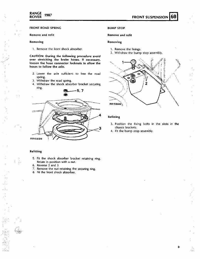
FRONT ROAD SPRING
Remove and refit
Removing
1. Remove the front shock absorber.
CAUTION: During the fol lowing procedure avoidover stretching the brake hoses. I f necessary,loosen the hose connector locknuts to allow thehoses to follow the axle.
2. Lower the axle suff icient to free the roadspring.
3. Withdraw the road spring.4. Withdraw the shock absorber bracket securing
ring.-57e
RR1593M T'M
BUMP STOP
Remove and refit
Removing
1. Remove the fixings.2. Withdraw the bump stop assembly.
Refitt ing
3 .
4 .
Position the fixing bolts in the slots in thechassis brackets.Fit the bump stop assembly.
Refitt ing
5. Fit the shock absorber bracket retaining ring.Retain in position with a nut.
6. Reverse 2 and 3.7. Remove the nut retaining the securing ring.8. Fit the front shock absorber.
3
RANGEFRONT SUSPENSION lggl R O V E R
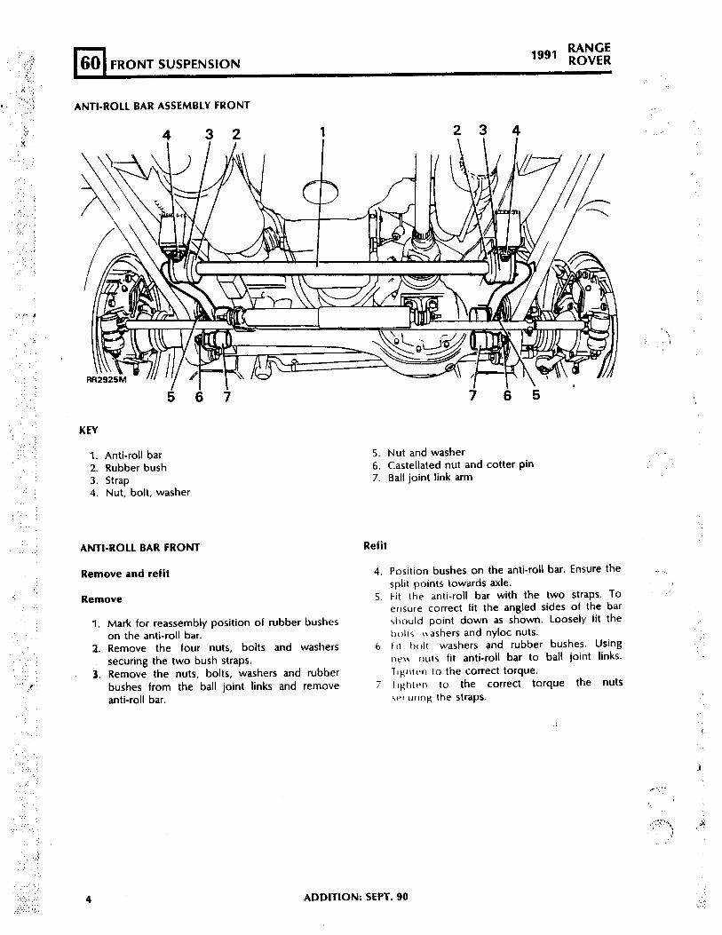
ANTI-ROLL BAR ASSEMBLY FRONT
23 4
KEY
1. Anti-roll bar2. Rubber bush3. Strap4. Nut, bolt, washer
ANTI-ROLL BAR FRONT Refit
Remove and refit
Remove
1. Mark for reassembly position of rubber busheson the anti-roll bar.
2. Remove the tour nuts, bolts and washerssecuring the two bush straps.
3. Remove the nuts, bolts, washers and rubberbushes from the ball joint links and removeanti-roll bar.
4
5. Nut and washer6. Castellated nut and cotter pin7. Ball joint link arm
4. Position bushes on the anti-roll bar. Ensure thesplit points towards axle.
5. F i t the anti-rol l bar with the two straps. TOensure correct fit the angled sides of the barshould point down as shown. Loosely fit thebolts isashers and nyloc nuts.
6 FII hrdt washers and rubber bushes. Usingne\\ IIUIS f i t anti-roll bar to ball joint l inks.TIghivn to the correct torque.
7 rlghlt~n to the correct torque the nutsWC urlng the straps.
.
ADDITION: SEPT. 90

..‘.>),..
. .:
‘.
:..
,:;.
,.:,
;g; 1991 FRONT SUSPENSION
ANTI-ROLL BAR BALL JOINT LINKS-FRONT
Remove and refit
Remove
1. Remove the two nuts, bolts, washers andrubber bushes from the ball joint links.
2. Remove cotter pin and loosen castellated nuta few turns.
3. Release ball joint using special tool 18C 1063Aas shown.
4. Remove castellated nut and ball joint link.
4 1 2 II II
RR2926M
Refit
5. Fit ball joint link and castellated nut. Ensurethe ball joint link arm points up. Tighten to thecorrect torque and fit new cotter pin.
6. Align anti-roll bar to ball joint links.7. Fi t bolts, washers and rubber bushes using
new self locking nuts secure anti-roll bar toball joint links. Tighten to the correct torque.
ADDITION: SEPT. SO

_:
,.’ ..I‘1
:,
._.
?’
. . .’

REAR SUSPENSION (64 1. . . . .,...
SELF LOCKING NUTS
Many steering and suspension items are securedusing self locking nuts.Where self locking nutshave been removed, they MUST be replaced withnew items of the correct type.
REAR ROAD SPRING
Remove and refit
Removing
1 .2.
3 .
4._'
Loosen the rear road wheel retaining nuts.Raise the rear of the vehicle using a suitablehydraulic floor jack. Support the chassis onstands and remove the wheels.Support the rear axle weight with the f loorjack.Disconnect the shock absorbers at one end.
5. Posit ion a suitable coil spring compressor
‘. correctly on the road spring.6. Compress the spring evenly to facil i tate
removal.7. Lower the axle suff icient to free the road
spring from the upper seat.
CAUTION: Avoid lowering the axle further thannecessary otherwise the rear brake flexible hosewil be damaged.
8. Remove the spring retainer plate.9. Withdraw the road spring.
10. Lift off the spring seat.
,i,:
I’
Refitt ing
11. Reverse 1 to IO. Ensure that the cotter pinsecuring the top shock absorber mounting islocated in the inboard hole.
REAR SHOCK ABSORBER
Remove and refit
Removing
Loosen the road wheel retaining nuts and raisethe rear of the vehicle using a suitablehydraulic floor jack.Support the chassis on stands. Remove theroad wheels and support the rear axle weightwith the floor jack.Remove the fixings and withdraw the shockabsorber frpm the axle bracket.
J51 l7M
REVISED: MARCH 90 1
KANGEREAR SUSPENSION 1987-90 ROVER
4. Remove upper fixings. 2. Remove excessive m u d deoosits f r o m
N O T E : j5llM s h o w s 1 9 9 0 M o d e l Y e a r t o pdamper fixing.
underneath the vehicle and any heavy itemsfrom inside the vehicle that are not part of theoriginal equipment.
.
5. Withdraw the shock absorber.6. If required, remove the mounting bracket at
the chassis side member.7. If required, lift out the mounting rubbers at
the upper end.
Refitting
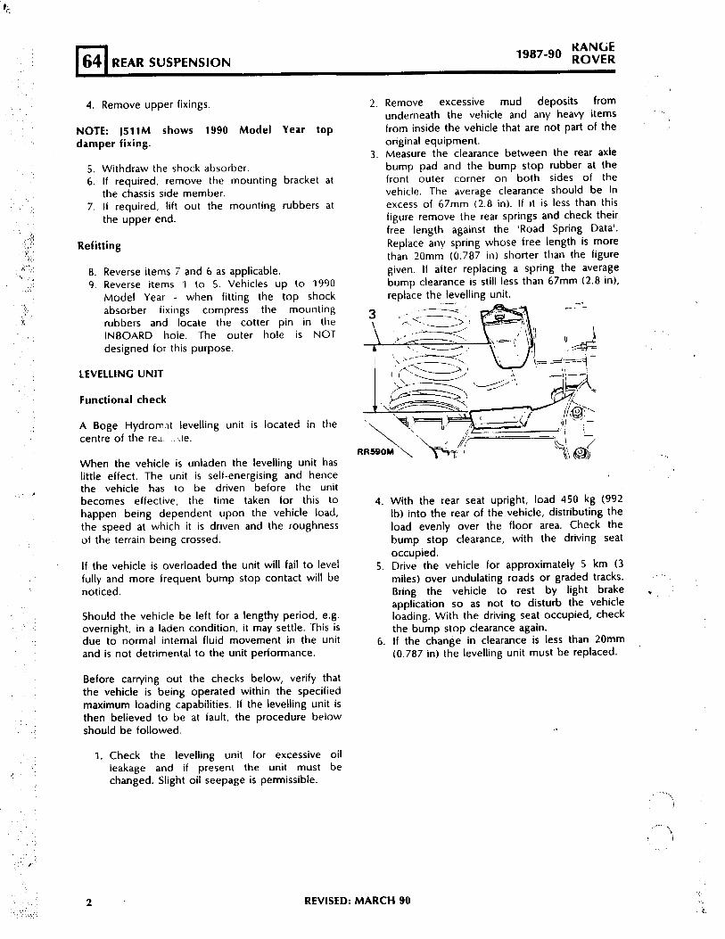
3. Measure the clearance between the rear axlebump pad and the bump stop rubber at thefront outer corner on both sides of thevehicle. The average clearance should be inexcess of 67mm (2.8 in). If it is less than thisfigure remove the rear springs and check theirfree length against the ‘Road Spring Data’.Replace any spring whose free length is morethan 20mm (0.787 in) shorter than the figuregiven. If after replacing a spring the averagebump clearance is still less than 67mm (2.8 in),replace the IevellinR unit.
8 .9 .
Reverse items 7 and 6 as applicable.Reverse items 1 to 5. Vehicles up to 1990Model Year - when fitting the top shockabsorber fixings compress the mountingrubbers and locate the cotter pin in theINBOARD hole. The outer hole is NOTdesigned for this purpose.
LEVELLING U N I T
Functional check
A Boge Hydromat levelling unit is located in thecentre of the red. .-.le.
When the vehicle is unladen the levelling unit haslittle effect. The unit is self-energising and hencethe vehicle has to be driven before the unitbecomes effective, the time taken for this tohappen being dependent upon the vehicle load,the speed at which it is driven and the roughnessof the terrain being crossed.
If the vehicle is overloaded the unit will fail to levelfully and more frequent bump stop contact will benoticed.
Should the vehicle be left for a lengthy period, e.g.overnight, in a laden condition, it may settle. This isdue to normal internal fluid movement in the unitand is not detrimental to the unit performance.
4 .
5 .
6 .
With the rear seat upright, load 450 kg (992lb) into the rear of the vehicle, distributing theload evenly over the floor area. Check thebump stop clearance, with the driving seatoccupied.Drive the vehicle for approximately 5 km (3miles) over undulating roads or graded tracks. ‘. ..Bring the vehicle to rest by light brake .application so as not to disturb the vehicleloading. With the driving seat occupied, checkthe bump stop clearance again.If the change in clearance is less than 20mm(0.787 in) the levelling unit-must be replaced.
Before carrying out the checks below, verify thatthe vehicle is being operated within the specifiedmaximum loading capabilities. If the levelling unit isthen believed to be at fault, the procedure belowshould be followed.
1. Check the levelling unit for excessive oilleakage and if present the unit must bechanged. Slight oil seepage is permissible.
2 REVISED: MARCH 90
PO;;; 1 9 8 7 - 9 0 REAR SUSPENSION
. ,
LEVELLINC U N I T
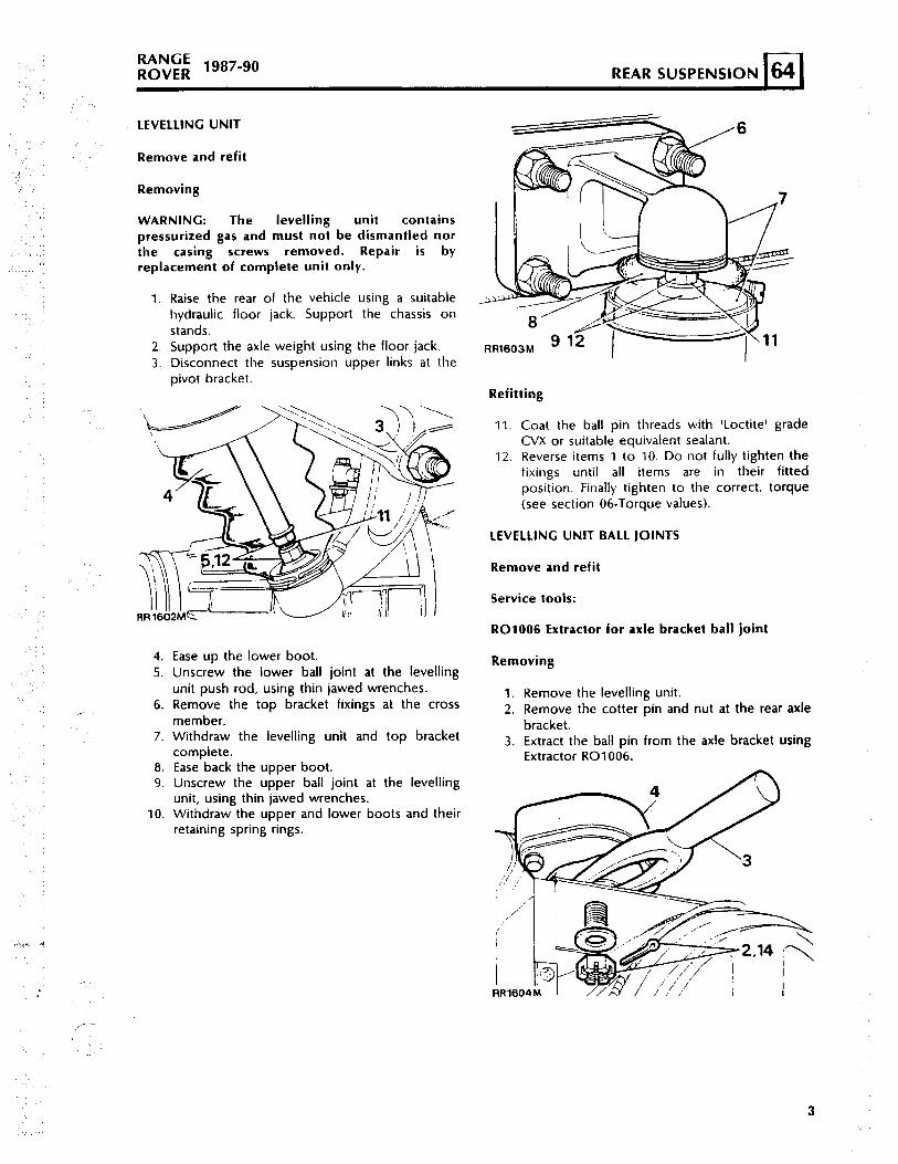
Remove and refit
Removing
WARNING: The levelling uni t containspressurized gas and must not be dismantled northe cas ing screws removed. Repair is byreplacement of complete unit only.
1. Raise the rear of the vehicle using a suitablehydraulic floor jack. Support the chassis onstands.
2. Support the axle weight using the floor jack.3. Disconnect the suspension upper links at the
pivot bracket.
4 .5 .
6 .,-
7 .
8.9 .
1 0 .
Ease up the lower boot.Unscrew the lower ball joint at the levellingunit push rod, using thin jawed wrenches.Remove the top bracket fixings at the crossmember.
Removing
1. Remove the levelling unit.2. Remove the cotter pin and nut at the rear axle
bracket.Withdraw the levelling unit and top bracketcomplete.
3. Extract the ball pin from the axle bracket usingExtractor R01006.
Ease back the upper boot.Unscrew the upper ball joint at the levellingunit, using thin jawed wrenches.Withdraw the upper and lower boots and theirretaining spring rings.
A
Refitt ing
11. Coat the ball pin threads with ‘Loctite’ gradeCVX or suitable equivalent sealant.
12. Reverse items 1 to 10. Do not fully tighten thefixings until all items are in their fittedposition. Finally tighten to the correct. torque(see section 06-Torque values).
LEVELLING UNIT BALL JOINTS
Remove and refit
Service tools:
R01006 Extractor for axle bracket ball joint
3

RANGEREAR SUSPENSION
1987-90 RO”ER
‘.a,
4. Withdraw the pivot bracket complete with balljoints.
5. Unscrew the ball joint assembly for thelevelling unit.
6. Remove the ball joint assembly from the axlebracket.
RR1605M
7 .
8 .
9 .
10.
11.
Replacement ball joints are supplied ascomplete assemblies, less f ixings, and arepre-packed with grease.The ball joint for the axle bracket must not bedismantled.The ball joints for the levelling unit may bedismantled and cleaned if required.Pack the ball joint with Dextagrease GP or anequivalent grease when assembling.Ensure that the ball seating is square in itshousing before refitting.
Refitting
1 2 .
13.
4
Press the knurled ball joint into the pivotbracket.Screw the ball joints for the levelling unit intothe mounting brackets. If the ball joints do notscrew in easi ly and ful ly, remove and theassemblies ensuring that the plastic seats donot jam in the housings. Tighten to the correcttorque (see section 06-Torque values).
14. Fit the pivot bracket complete with ball jointsto the rear axle. Tighten to the correct torque(see section 06-Torque values).
15. Fit the levelling unit.
BUMP STOP
Remove and refit
Removing
1. Rernove the fixings.2. Withdraw the bump stop assembly.
RR 1607M
Refitting
3. Posit ion the f ixing bolts in the ~101s in thechassis brackets.
4 . Fi+ the bump stop assembly, posrtion the _I . . . .
snoulder on the carrier to suit tht: chassis !configuration.

. ’ :
.:
..:: .
.‘),’ :.
‘,.. .:. ’ ?,:.
I . ‘..‘.’x
. . . . :
KnlYutROVER lg8’ REAR SUSPENSION
UPPER SUSPENSION LINK Replacing the bush
.’ Remove and refit 1 to 6 and 9
BUSH
Remove and refit 7 and 8
Removing
1. Raise the rear of the vehicle using a suitablehydraulic floor jack. Support the rear of thechassis on stands allowing the axle to be freelysuspended.
2 . Remove the f i x ings , upper l ink bracket tof rame.
,/
3 .
4 .
5 .-..6 .
Remove the f i x ings , upper l inks to p ivotbracket .Withdraw the upper link complete with framebracket.Remove the fixing bolt.Separate link and bush assembly from bracket.
7. Using a suitable hydraulic or bench press anda piece of metal tubing slightly smaller thanthe outside diameter of the bush, press outthe rubber mounted bushes. Ensure the steeltubing locates on the outer edge of the bushand not on the rubber inner.
8. Fit the replacement bush assembly centrally inthe housing.
CAUTION: When pressing in the new bushesensure that pressure is applied to the outer edge01 the bush only and not to the rubber inner.
Refitting
9. Reverse 1 to 6. Do not fully tighten the fixingsuntil all components are in position.
10. Finally tighten all fixings to the correct torque(See Section 06 Torque Values).
REVISED: jUl.Y 88
l-l64 REAR SUSPENSIONRANGE
“*’ R O V E R
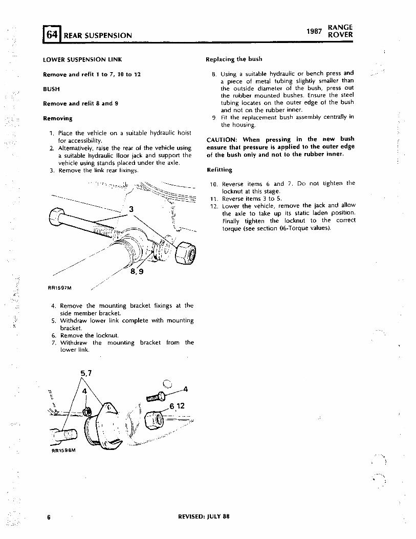
LOWER SUSPENSION LINK Replacing the bush
Remove and refit 1 to 7, 10 to 12
BUSH
Remove and refit 8 and 9
Removing
1. Place the vehicle on a suitable hydraulic hoistfor accessibility.
2. Alternatively, raise the rear of the vehicle usinga suitable hydraulic floor jack and support thevehicle using stands placed under the axle.
3. Remove the link rear fixings.
RR1597M /"
4. Remove the mounting bracket fixings at theside member bracket.
5. Withdraw lower link complete with mountingbracket.
6. Remove the locknut.7. Withdraw the mounting bracket from the
lower link.
6. REVISED: JULY 88
8. Using a suitable hydraulic or bench press anda piece of metal tubing slightly smaller thanthe outside diameter of the bush, press outthe rubber mounted bushes. Ensure the steeltubing locates on the outer edge of the bushand not on the rubber inner.
9. Fit the replacement bush assembly centrally inthe housing.
CAUTION: When pressing in the new bushensure that pressure is applied to the outer edgeof the bush only and not to the rubber inner.
Refitt ing
1 0 .
1 1 .12.
Reverse items 6 and 7. Do not tighten thelocknut at this stage.Reverse items 3 to 5.Lower the vehicle, remove the jack and allowthe axle to take up its static laden position.Finally tighten the locknut to the correcttorque (see section 06-Torque values).
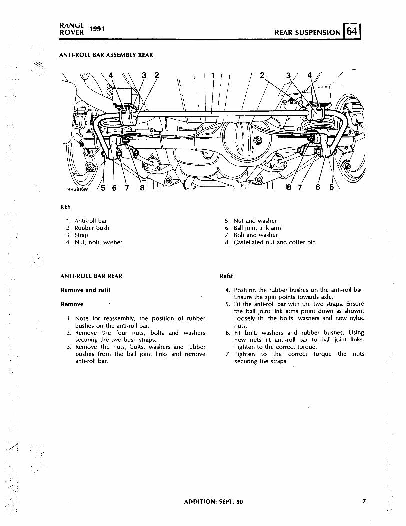
R”\$ 1991REAR SUSPENSION
ANTI-ROLL BAR ASSEMBLY REAR
KEY
1. Anti-roll bar2 . Rubber bush3. Strap4. Nut, bolt, washer
ANTI-ROLL BAR REAR
Remove and refit
Remove
1. Note for reassembly, the posit ion of rubberbushes on the anti-roll bar.
2. Remove the four nuts, bolts and washerssecuring the two bush straps.
3. Remove the nuts, bolts, washers and rubberbushes from the ball joint links and removeanti-roll bar.
5. Nut and washer6. Ball joint link arm7. Bolt and washer8. Castellated nut and cotter pin
Refit
4. Position the rubber bushes on the anti-roll bar.Ensure the split points towards axle.
5. Fit the anti-roll bar with the two straps. Ensurethe ball joint link arms point down as shown.Loosely fit, the bolts, washers and new nylocnuts.
6. Fi t bolt , washers and rubber bushes. Usingnew nuts f i t anti-roll bar to ball joint l inks.Tighten to the correct torque.
7 . T i g h t e n t o t h e c o r r e c t t o r q u e t h e n u t ssecuring the straps.
,‘.
‘,
:
.,,‘. .:
ADDITION: SEPT. 90 7
