self-adaptable security monitoring for iaas cloud environments
TRANSCRIPT

HAL Id: tel-01653831https://hal.inria.fr/tel-01653831v2
Submitted on 20 Apr 2018
HAL is a multi-disciplinary open accessarchive for the deposit and dissemination of sci-entific research documents, whether they are pub-lished or not. The documents may come fromteaching and research institutions in France orabroad, or from public or private research centers.
L’archive ouverte pluridisciplinaire HAL, estdestinée au dépôt et à la diffusion de documentsscientifiques de niveau recherche, publiés ou non,émanant des établissements d’enseignement et derecherche français ou étrangers, des laboratoirespublics ou privés.
Self-adaptable Security Monitoring for IaaS CloudEnvironmentsAnna Giannakou
To cite this version:Anna Giannakou. Self-adaptable Security Monitoring for IaaS Cloud Environments. Cryptographyand Security [cs.CR]. INSA de Rennes, 2017. English. �NNT : 2017ISAR0021�. �tel-01653831v2�
THESE INSA Rennessous le sceau de l’Université Bretagne Loire
pour obtenir le titre deDOCTEUR DE L’INSA RENNES
Spécialité : Informatique
présentée par
Anna GiannakouECOLE DOCTORALE : MatisseLABORATOIRE : Irisa
Self-adaptable SecurityMonitoring for IaaS
Cloud Environments
Thèse soutenue le 06.07.2017 devant le jury composé de :
Eric TotelProfesseur, Centrale-Supélec / PrésidentSara BouchenakProfesseur, INSA Lyon / RapporteurHervé DebarProfesseur, Télécom SudParis / RapporteurEddy CaronMaître de Conférences, HDR, ENS Lyon / ExaminateurStephen ScottProfesseur, Tennessee Tech University / ExaminateurChristine MorinDirectrice de Recherche, INRIA Rennes / Co-directrice de thèseJean-Louis PazatProfesseur, INSA Rennes / Directeur de thèseLouis RillingIngénieur-Chercheur, DGA MI / Co-encadrant de thèse

Self-adaptable Security Monitoring for IaaS Cloud Environments
Anna Giannakou
Document protégé par les droits d’auteur

Publications:
o National ▪ Workshops :
• Giannakou, Anna, Louis Rilling, Frédéric Majorczyk, Jean-Louis Pazat, and Christine Morin. “Self Adaptation in Security Monitoring for IaaS clouds”. In: EIT Digital Future Cloud symposium, Rennes, France, October 19-20, 2015
o International
▪ Conferences :
• Giannakou,Anna,Louis Rilling,Jean-Louis Pazat,andChristine Morin.“AL-SAFE: A Secure Self-Adaptable Application-Level Firewall for IaaS Clouds”. In: 2016 IEEE International Conference on Cloud Computing Technology and Science, CloudCom 2016,Luxembourg, Luxembourg, December 12-15, 2016, pp. 383–390
• Giannakou, Anna, Louis Rilling, Jean-Louis Pazat, Frédéric Majorczyk, and Chris- tine Morin. “Towards Self Adaptable Security Monitoring in IaaS Clouds”. In: 15th IEEE/ACM International Symposium on Cluster, Cloud and Grid Computing, CC- Grid 2015, Shenzhen, China, May 4-7, 2015, pp. 737–740.
▪ Workshops :
• Giannakou, Anna, Louis Rilling, Jean-Louis Pazat, and Christine Morin. “How to Secure Application-Level Firewalls in IaaS Clouds”. In: International Workshop on Cloud Data and Platforms, CloudDP, London, UK, April 17, 2016
Acknowledgements
First and foremost I would like to like to thank my advisors for their outstanding guidanceand support throughout the duration of this thesis. Christine, thank you for continuouslyreviewing my work, offering important insights and improvements. Your advice regardingmy professional development after the PhD helped me make important decisions aboutmy future. During the last three and a half years you have been a role model for me asa woman in research. Louis, words cannot express how grateful I am for your guidanceand support all these years. You have taught me so many things and helped me achievemy goals at so many different levels. Thank you for showing me all these new directionsand possibilities and for helping me grow as a researcher. Also, thank you for tirelesslylistening me complain about not having enough results :). Jean-Louis, I am grateful foryour guidance throughout the whole process.
Furthermore, I would like to thank the members of my committee and especially thereviewers Sara Bouchenak and Herve Debar for evaluating my work. Special thanks goesout to all the members of the Myriads team for creating a warm and welcoming atmo-sphere at the office. David, Yunbo and Amir, for all of our discussions and for being suchwonderful people to interact with. Deb and Sean, thank you for hosting me at LawrenceBerkeley National Lab for my three month internship and for allowing me to explore newresearch directions.
This thesis would not have been possible without the endless love and support of myfriends and family. Genc, I am so grateful that I have met you and I am proud to callyou my buddinis. Thank you for listening my complains offering helpful insights everytime I invaded your office :). Bogdan and Mada, you have both been so wonderful andspecial to me. To Tsiort, Magnum, Ziag and Fotis thank you for your honest and deepsupport throughout these years from thousands of miles away. I love and miss you guys somuch. To Irene, you have been nothing less than exceptional, kolitoula. I cannot expresshow deeply grateful I am for your endless encouragement and advice all this time. ToIakovos, thank you for your stoic comments and for all of our arguments :). To Eri, thankyou for all your support and your clear-headed guidance throughout these years. Youare admirable and you have given me so much. To my parents, thank you for your love,patience and support that has allowed me to pursue my ambitions. Thank you for raisingme as a strong independent person and for showing me the benefits of persistence. To mysister Maria, thank you for being there, always.
Finally, the biggest thank you goes out to a single person that has been by my side forthe last five years. Ismael, words cannot describe how grateful I am for all the things thatyou have given me throughout this period. Thank you for helping me break my personaldeadlocks in so many levels and for adding all these new dimensions in my life. I couldnot have done this without you and I will never forget that. I love you, always, my sunand stars.

2

Contents
1 Introduction 11
1.1 Context . . . . . . . . . . . . . . . . . . . . . . . . . . . . . . . . . . . . . . 11
1.2 Motivation . . . . . . . . . . . . . . . . . . . . . . . . . . . . . . . . . . . . 11
1.3 Objectives . . . . . . . . . . . . . . . . . . . . . . . . . . . . . . . . . . . . . 12
1.3.1 Self-Adaptation . . . . . . . . . . . . . . . . . . . . . . . . . . . . . . 12
1.3.2 Tenant-Driven Customization . . . . . . . . . . . . . . . . . . . . . . 12
1.3.3 Security and Correctness . . . . . . . . . . . . . . . . . . . . . . . . 13
1.3.4 Cost Minimization . . . . . . . . . . . . . . . . . . . . . . . . . . . . 13
1.4 Contributions . . . . . . . . . . . . . . . . . . . . . . . . . . . . . . . . . . . 13
1.4.1 A Self-Adaptable Security Monitoring Framework . . . . . . . . . . 13
1.4.2 SAIDS . . . . . . . . . . . . . . . . . . . . . . . . . . . . . . . . . . . 13
1.4.3 AL-SAFE . . . . . . . . . . . . . . . . . . . . . . . . . . . . . . . . . 14
1.5 Thesis Outline . . . . . . . . . . . . . . . . . . . . . . . . . . . . . . . . . . 14
2 State of the Art 17
2.1 Autonomic Computing . . . . . . . . . . . . . . . . . . . . . . . . . . . . . . 17
2.1.1 What is Autonomic Computing? . . . . . . . . . . . . . . . . . . . . 17
2.1.2 Characteristics . . . . . . . . . . . . . . . . . . . . . . . . . . . . . . 17
2.1.3 The Role of the Manager . . . . . . . . . . . . . . . . . . . . . . . . 18
2.2 Cloud Computing . . . . . . . . . . . . . . . . . . . . . . . . . . . . . . . . . 19
2.2.1 What is Cloud Computing? . . . . . . . . . . . . . . . . . . . . . . . 19
2.2.2 Characteristics . . . . . . . . . . . . . . . . . . . . . . . . . . . . . . 20
2.2.3 Service Models . . . . . . . . . . . . . . . . . . . . . . . . . . . . . . 20
2.2.4 Deployment Models . . . . . . . . . . . . . . . . . . . . . . . . . . . 22
2.2.5 Dynamic Events in Iaas Clouds and Cloud Adaptation . . . . . . . . 23
2.3 Virtualization . . . . . . . . . . . . . . . . . . . . . . . . . . . . . . . . . . . 24
2.3.1 Server Virtualization Components . . . . . . . . . . . . . . . . . . . 24
2.3.2 Server Virtualization . . . . . . . . . . . . . . . . . . . . . . . . . . . 24
2.3.3 Network Virtualization and Network Management in IaaS Clouds . . 27
2.4 Security Threats . . . . . . . . . . . . . . . . . . . . . . . . . . . . . . . . . 29
2.4.1 Security Threats in Information Systems . . . . . . . . . . . . . . . . 29
2.4.2 Security Threats in Cloud Environments . . . . . . . . . . . . . . . . 32
2.4.3 Summary . . . . . . . . . . . . . . . . . . . . . . . . . . . . . . . . . 33
2.5 Security Monitoring . . . . . . . . . . . . . . . . . . . . . . . . . . . . . . . 33
2.5.1 What is Security Monitoring? . . . . . . . . . . . . . . . . . . . . . . 33
2.5.2 Security Monitoring in Cloud Environments . . . . . . . . . . . . . . 38
2.6 Summary . . . . . . . . . . . . . . . . . . . . . . . . . . . . . . . . . . . . . 50
3

4
3 A Self-Adaptable Security Monitoring Framework for IaaS Clouds 53
3.1 Introduction . . . . . . . . . . . . . . . . . . . . . . . . . . . . . . . . . . . . 53
3.2 System Model . . . . . . . . . . . . . . . . . . . . . . . . . . . . . . . . . . . 54
3.3 Threat Model . . . . . . . . . . . . . . . . . . . . . . . . . . . . . . . . . . . 54
3.4 Objectives . . . . . . . . . . . . . . . . . . . . . . . . . . . . . . . . . . . . . 55
3.4.1 Self Adaptation . . . . . . . . . . . . . . . . . . . . . . . . . . . . . . 55
3.4.2 Tenant-Driven Customization . . . . . . . . . . . . . . . . . . . . . . 55
3.4.3 Security and Correctness . . . . . . . . . . . . . . . . . . . . . . . . 56
3.4.4 Cost Minimization . . . . . . . . . . . . . . . . . . . . . . . . . . . . 56
3.5 Example Scenario . . . . . . . . . . . . . . . . . . . . . . . . . . . . . . . . . 56
3.6 Adaptation Process . . . . . . . . . . . . . . . . . . . . . . . . . . . . . . . . 57
3.7 Architecture . . . . . . . . . . . . . . . . . . . . . . . . . . . . . . . . . . . . 58
3.7.1 High-Level Overview . . . . . . . . . . . . . . . . . . . . . . . . . . . 58
3.7.2 Tenant-API . . . . . . . . . . . . . . . . . . . . . . . . . . . . . . . . 59
3.7.3 Security Devices . . . . . . . . . . . . . . . . . . . . . . . . . . . . . 62
3.7.4 Adaptation Manager . . . . . . . . . . . . . . . . . . . . . . . . . . . 62
3.7.5 Infrastructure Monitoring Probes . . . . . . . . . . . . . . . . . . . . 64
3.7.6 Component Dependency Database . . . . . . . . . . . . . . . . . . . 64
3.8 Implementation . . . . . . . . . . . . . . . . . . . . . . . . . . . . . . . . . . 65
3.8.1 Adaptation Manager . . . . . . . . . . . . . . . . . . . . . . . . . . . 65
3.8.2 Infrastructure Monitoring Probe . . . . . . . . . . . . . . . . . . . . 67
3.9 Summary . . . . . . . . . . . . . . . . . . . . . . . . . . . . . . . . . . . . . 67
4 SAIDS: A Self-Adaptable Intrusion Detection System for IaaS CloudEnvironments 69
4.1 Objectives . . . . . . . . . . . . . . . . . . . . . . . . . . . . . . . . . . . . . 69
4.2 Models and Architecture . . . . . . . . . . . . . . . . . . . . . . . . . . . . . 70
4.2.1 Architecture . . . . . . . . . . . . . . . . . . . . . . . . . . . . . . . 70
4.3 Security Threats . . . . . . . . . . . . . . . . . . . . . . . . . . . . . . . . . 72
4.3.1 SAIDS Configuration Files . . . . . . . . . . . . . . . . . . . . . . . 72
4.3.2 LIDS Rules . . . . . . . . . . . . . . . . . . . . . . . . . . . . . . . . 73
4.3.3 SAIDS Adaptation Sources . . . . . . . . . . . . . . . . . . . . . . . 73
4.3.4 Connection Between SAIDS Components . . . . . . . . . . . . . . . 73
4.3.5 External Traffic . . . . . . . . . . . . . . . . . . . . . . . . . . . . . . 73
4.4 Adaptation process . . . . . . . . . . . . . . . . . . . . . . . . . . . . . . . . 74
4.4.1 Events Triggering Adaptation . . . . . . . . . . . . . . . . . . . . . . 74
4.4.2 Adaptation Process . . . . . . . . . . . . . . . . . . . . . . . . . . . 74
4.4.3 Topology-Related Change . . . . . . . . . . . . . . . . . . . . . . . . 75
4.4.4 Traffic-Related Change . . . . . . . . . . . . . . . . . . . . . . . . . . 76
4.4.5 Service-Related Change . . . . . . . . . . . . . . . . . . . . . . . . . 76
4.5 Implementation . . . . . . . . . . . . . . . . . . . . . . . . . . . . . . . . . . 77
4.6 Evaluation . . . . . . . . . . . . . . . . . . . . . . . . . . . . . . . . . . . . . 78
4.6.1 Objectives of the Evaluation . . . . . . . . . . . . . . . . . . . . . . 78
4.6.2 Experimentation Methodology . . . . . . . . . . . . . . . . . . . . . 81
4.6.3 Result Analysis . . . . . . . . . . . . . . . . . . . . . . . . . . . . . . 83
4.7 Summary . . . . . . . . . . . . . . . . . . . . . . . . . . . . . . . . . . . . . 90

Contents 5
5 AL-SAFE: A Secure Self-Adaptable Application-Level Firewall for IaaSClouds 935.1 Requirements . . . . . . . . . . . . . . . . . . . . . . . . . . . . . . . . . . . 93
5.1.1 Why Should we Secure an Application-level Firewall . . . . . . . . . 945.1.2 Security and Visibility . . . . . . . . . . . . . . . . . . . . . . . . . . 945.1.3 Self-Adaptable Application-Level Firewall . . . . . . . . . . . . . . . 94
5.2 Models and Architecture . . . . . . . . . . . . . . . . . . . . . . . . . . . . . 955.2.1 Events that Trigger Adaptation . . . . . . . . . . . . . . . . . . . . . 955.2.2 Component Description . . . . . . . . . . . . . . . . . . . . . . . . . 95
5.3 Adaptation Process . . . . . . . . . . . . . . . . . . . . . . . . . . . . . . . . 975.3.1 Security Threats . . . . . . . . . . . . . . . . . . . . . . . . . . . . . 100
5.4 Implementation . . . . . . . . . . . . . . . . . . . . . . . . . . . . . . . . . . 1015.4.1 Edge Firewall . . . . . . . . . . . . . . . . . . . . . . . . . . . . . . . 1015.4.2 Switch-Level Firewall . . . . . . . . . . . . . . . . . . . . . . . . . . 1015.4.3 VMI . . . . . . . . . . . . . . . . . . . . . . . . . . . . . . . . . . . . 1015.4.4 Information Extraction Agent . . . . . . . . . . . . . . . . . . . . . . 1045.4.5 Rule Generators . . . . . . . . . . . . . . . . . . . . . . . . . . . . . 105
5.5 Evaluation Methodology . . . . . . . . . . . . . . . . . . . . . . . . . . . . . 1055.5.1 Objectives of the Evaluation . . . . . . . . . . . . . . . . . . . . . . 1055.5.2 Experimentation Methodology . . . . . . . . . . . . . . . . . . . . . 107
5.6 Evaluation Results . . . . . . . . . . . . . . . . . . . . . . . . . . . . . . . . 1145.6.1 Performance and Cost Analysis . . . . . . . . . . . . . . . . . . . . . 1145.6.2 Correctness Analysis . . . . . . . . . . . . . . . . . . . . . . . . . . . 1225.6.3 Limitations . . . . . . . . . . . . . . . . . . . . . . . . . . . . . . . . 123
5.7 Summary . . . . . . . . . . . . . . . . . . . . . . . . . . . . . . . . . . . . . 124
6 Conclusion 1256.1 Contributions . . . . . . . . . . . . . . . . . . . . . . . . . . . . . . . . . . . 1256.2 Future Work . . . . . . . . . . . . . . . . . . . . . . . . . . . . . . . . . . . 127
6.2.1 Short-Term Goals . . . . . . . . . . . . . . . . . . . . . . . . . . . . 1276.2.2 Mid-Term Goals . . . . . . . . . . . . . . . . . . . . . . . . . . . . . 1286.2.3 Long-Term Goals . . . . . . . . . . . . . . . . . . . . . . . . . . . . . 130
Annexe A Resume en francais 143A.1 Contexte . . . . . . . . . . . . . . . . . . . . . . . . . . . . . . . . . . . . . . 143A.2 Motivation . . . . . . . . . . . . . . . . . . . . . . . . . . . . . . . . . . . . 144A.3 Objectifs . . . . . . . . . . . . . . . . . . . . . . . . . . . . . . . . . . . . . . 144
A.3.1 Auto-adaptation . . . . . . . . . . . . . . . . . . . . . . . . . . . . . 144A.3.2 Personnalisation . . . . . . . . . . . . . . . . . . . . . . . . . . . . . 145A.3.3 Securite et correction . . . . . . . . . . . . . . . . . . . . . . . . . . 145A.3.4 Minimisation des couts . . . . . . . . . . . . . . . . . . . . . . . . . . 145
A.4 Contributions . . . . . . . . . . . . . . . . . . . . . . . . . . . . . . . . . . . 145A.4.1 Un systeme de supervision de securite auto-adaptatif . . . . . . . . . 146A.4.2 SAIDS . . . . . . . . . . . . . . . . . . . . . . . . . . . . . . . . . . . 146A.4.3 AL-SAFE . . . . . . . . . . . . . . . . . . . . . . . . . . . . . . . . . 147
A.5 Perspectives . . . . . . . . . . . . . . . . . . . . . . . . . . . . . . . . . . . . 147A.5.1 Perspectives a court terme . . . . . . . . . . . . . . . . . . . . . . . . 147A.5.2 Perspectives a moyen terme . . . . . . . . . . . . . . . . . . . . . . . 147A.5.3 Perspectives a long terme . . . . . . . . . . . . . . . . . . . . . . . . 148

6

List of Figures
2.1 The MAPE control loop . . . . . . . . . . . . . . . . . . . . . . . . . . . . . 19
2.2 The OpenStack architecture . . . . . . . . . . . . . . . . . . . . . . . . . . . 22
2.3 The SDN architecture . . . . . . . . . . . . . . . . . . . . . . . . . . . . . . 28
2.4 Information system with different security devices contributing to securitymonitoring . . . . . . . . . . . . . . . . . . . . . . . . . . . . . . . . . . . . 34
2.5 A DMZ example . . . . . . . . . . . . . . . . . . . . . . . . . . . . . . . . . 37
2.6 Hypervisor and host OS kernel . . . . . . . . . . . . . . . . . . . . . . . . . 39
2.7 The Cloud IDS architecture as in [1] . . . . . . . . . . . . . . . . . . . . . . 43
2.8 The Livewire architecture as in [2] . . . . . . . . . . . . . . . . . . . . . . . 44
2.9 CloudSec architecture as in [3] . . . . . . . . . . . . . . . . . . . . . . . . . 46
3.1 An example of a cloud hosted information system . . . . . . . . . . . . . . . 56
3.2 The framework’s architecture . . . . . . . . . . . . . . . . . . . . . . . . . . 59
3.3 The framework’s different levels . . . . . . . . . . . . . . . . . . . . . . . . . 60
4.1 SAIDS architecture . . . . . . . . . . . . . . . . . . . . . . . . . . . . . . . . 71
4.2 Migration time with and without SAIDS . . . . . . . . . . . . . . . . . . . . 84
4.3 Adaptation time breakdown when SAIDS only reconfigures the enforcedruleset inside the LIDS . . . . . . . . . . . . . . . . . . . . . . . . . . . . . . 84
4.4 Adaptation time breakdown when SAIDS has to start a new LIDS, dis-tribute traffic and create a mirroring tunnel . . . . . . . . . . . . . . . . . . 85
4.5 MAD scalability setup . . . . . . . . . . . . . . . . . . . . . . . . . . . . . . 86
4.6 MAD response time . . . . . . . . . . . . . . . . . . . . . . . . . . . . . . . 86
4.7 AM scalability setup . . . . . . . . . . . . . . . . . . . . . . . . . . . . . . . 87
4.8 AM response time . . . . . . . . . . . . . . . . . . . . . . . . . . . . . . . . 88
5.1 The AL-SAFE architecture with the Adaptation Manager . . . . . . . . . . 96
5.2 Steps of the AL-SAFE adaptation . . . . . . . . . . . . . . . . . . . . . . . 98
5.3 The migration request arrives between two introspections . . . . . . . . . . 99
5.4 The migration request arrives during an introspection . . . . . . . . . . . . 99
5.5 LibVMI stack . . . . . . . . . . . . . . . . . . . . . . . . . . . . . . . . . . . 102
5.6 Adaptation process flow chart . . . . . . . . . . . . . . . . . . . . . . . . . . 103
5.7 Snapshot-Introspection relationship . . . . . . . . . . . . . . . . . . . . . . . 104
5.8 TCP server setup . . . . . . . . . . . . . . . . . . . . . . . . . . . . . . . . . 111
5.9 TCP client setup . . . . . . . . . . . . . . . . . . . . . . . . . . . . . . . . . 112
5.10 UDP setup . . . . . . . . . . . . . . . . . . . . . . . . . . . . . . . . . . . . 113
5.11 Migration time with and without adaptation . . . . . . . . . . . . . . . . . 114
5.12 Breakdown of each phase in seconds . . . . . . . . . . . . . . . . . . . . . . 115
5.13 Impact of the introspection period on kernel compilation time . . . . . . . . 115
7

8
5.14 Impact of the introspection period on server throughput . . . . . . . . . . . 1165.15 Request service time for different times in the introspection cycle . . . . . . 1175.16 Cases of request arrival time with respect to the introspection cycle . . . . . 1175.17 Impact of the introspection period on network throughput . . . . . . . . . . 1185.18 Cases of request arrival time with respect to the introspection cycle . . . . . 1195.19 Inbound TCP connection establishment time . . . . . . . . . . . . . . . . . 1205.20 Outbound TCP connection establishment time . . . . . . . . . . . . . . . . 1215.21 Inbound UDP round trip time . . . . . . . . . . . . . . . . . . . . . . . . . . 121
List of Tables
3.1 The VM info table . . . . . . . . . . . . . . . . . . . . . . . . . . . . . . . . 653.2 The Device info table . . . . . . . . . . . . . . . . . . . . . . . . . . . . . . 65
4.1 Events that trigger adaptation . . . . . . . . . . . . . . . . . . . . . . . . . 744.2 Resource consumption of the AM component . . . . . . . . . . . . . . . . . 89
5.1 Events that trigger adaptation . . . . . . . . . . . . . . . . . . . . . . . . . 955.2 Resource consumption of the introspection component . . . . . . . . . . . . 122
9

10
Chapter 1
Introduction
1.1 Context
Server virtualization enables on-demand allocation of computational resources (e.g. CPUand RAM) according to the pay-as-you-go model, a business model where users (referredto as tenants) are charged only for as much as they have used. One of the main cloudmodels that has gained significant attention over the past few years is the Infrastructure asa Service model where compute, storage, and network resources are provided to tenantsin the form of virtual machines (VMs) and virtual networks. Organizations outsourcepart of their information systems to virtual infrastructures (composed of VMs and virtualnetworks) hosted on the physical infrastructure of the cloud provider. The terms thatregulate the resource allocation are declared in a contract signed by the tenants andthe cloud provider, the Service Level Agreement (SLA) [4]. Few of the main benefits ofthe IaaS cloud include: flexibility in resource allocation, illusion of unlimited capacity ofcomputational and network resources and automated administration of complex virtualizedinformation systems.
Although shifting to the cloud might provide significant cost and efficiency gains, secu-rity continues to remain one of the main concerns in the adoption of the cloud model [5].Multi-tenancy, one of the key characteristics of a cloud infrastructure, creates the possi-bility of legitimate VMs being colocated with malicious, attacker-controlled VMs. Con-sequently, attacks towards cloud infrastructures may originate from inside as well as theoutside of the cloud environment [6]. A successful attack could allow attackers to gainaccess and manipulate cloud-hosted data including legitimate user’s account credentialsor even gain complete control of the cloud infrastructure and turn it into a maliciousentity [7]. Although traditional security techniques such as traffic filtering or traffic in-spection can provide a certain level of protection against attackers, they are not enoughto tackle sophisticated threats that target virtual infrastructures. In order to provide asecurity solution for cloud environments, an automated self-contained security architecturethat integrates heterogeneous security and monitoring tools is required.
1.2 Motivation
In a typical IaaS cloud environment, the provider is responsible for the management andmaintenance of the physical infrastructure while tenants are only responsible for managingtheir own virtualized information system. Tenants can make decisions regarding VM life-cycle and deploy different types of applications on their provisioned VMs. Since deployed
11

12 CHAPTER 1. INTRODUCTION
applications may have access to sensitive information or perform critical operations, ten-ants are concerned with the security monitoring of their virtualized infrastructure. Theseconcerns can be expressed in the form of monitoring requirements against specific types ofthreats. Security monitoring solutions for cloud environments are typically managed bythe cloud provider and are composed of heterogeneous tools for which manual configura-tion is required. In order to provide successful detection results, monitoring solutions needto take into account the profile of tenant-deployed applications as well as specific tenantsecurity requirements.
A cloud environment exhibits a very dynamic behavior with changes that occur atdifferent levels of the cloud infrastructure. Unfortunately, these changes affect the abilityof a cloud security monitoring framework to successfully detect attacks and preserve theintegrity of the cloud infrastructure [8]. Existing cloud security monitoring solutions fail toaddress changes and take necessary decisions regarding the reconfiguration of the securitydevices. As a result, new entry points for malicious attackers are created which may leadto a compromise of the whole cloud infrastructure. To our knowledge, there still doesnot exist a security monitoring framework that is able to adapt its components based ondifferent changes that occur in a cloud environment.
The goal of this thesis is to design and implement a self-adaptable security monitoringframework that is able to react to dynamic events that occur in a cloud infrastructure andadapt its components in order to guarantee that an adequate level of security monitoringfor tenant’s virtual infrastructures is achieved.
1.3 Objectives
After presenting the context and motivation for this thesis we now define a set of objectivesfor a self-adaptable security monitoring framework.
1.3.1 Self-Adaptation
A self-adaptable security monitoring framework should be able to adapt its componentsbased on different types of dynamic events that occur in a cloud infrastructure. Theframework should perceive these events as sources of adaptation and take subsequentactions that affect its components. The adaptation process may alter the configuration ofexisting monitoring devices or instantiate new ones. The framework may decide to alterthe computational resources available to a monitoring device (or a subset of monitoringdevices) in order to maintain an adequate level of monitoring. Adaptation of the amount ofcomputational resources should also be performed in order to free under-utilized resources.The framework should make adaptation decisions in order to guarantee that a balancedtrade-off between security, performance and cost is maintained at any given moment.Adaptation actions can affect different components and the framework should be able toperform these actions in parallel.
1.3.2 Tenant-Driven Customization
Tenant requirements regarding specific monitoring cases should be taken into account froma self-adaptable security monitoring framework. The framework should be able to guaran-tee that adequate monitoring for specific tenant-requested types of threats will be provided.The monitoring request could refer to a tenant’s whole virtual infrastructure or to a spe-cific subset of VMs. The framework should provide the requested type of monitoring until

1.4. CONTRIBUTIONS 13
the tenant requests otherwise or the subset of VMs that the monitoring type is appliedto no longer exists. Furthermore, the framework should take into account tenant-defined(through specific SLAs) thresholds that refer to the quality of the monitoring service orto the performance of specific types of monitoring devices.
1.3.3 Security and Correctness
Deploying a self-adaptable security monitoring framework should not add new vulnera-bilities in the monitored virtual infrastructure or in the provider’s infrastructure. Theadaptation process and the input sources required should not create new entry points foran attacker. Furthermore, a self-adaptable security monitoring framework should be ableto guarantee that an adequate level of monitoring is maintained throughout the adaptationprocess. The adaptation process should not intervene with the ability of the frameworkto correctly detect threats.
1.3.4 Cost Minimization
Deploying a self-adaptable security monitoring framework should not significantly impactthe trade-off between security and cost for both tenants and the provider. On the ten-ant’s side a self-adaptable security monitoring framework should not significantly impactperformance of the applications that are hosted in the virtual infrastructure regardless ofthe application profile (compute- or network-intensive). On the provider’s side, the abil-ity to generate profit by leasing it’s computational resources should not be significantlyaffected by the framework. Deploying such a framework should not impose a significantpenalty in normal cloud operations (e.g. VM migration, creation, etc). Furthermore, theamount of computational resources dedicated to the self-adaptable framework’s compo-nents should reflect an agreement between tenants and the provider for the distributionof computational resources.
1.4 Contributions
In order to achieve the objectives presented in the previous section, we design a self-adaptable security monitoring that is able to address limitations in existing monitoringframeworks and tackle dynamic events that occur in a cloud infrastructure. In this thesiswe detail how we designed, implemented, and evaluated our contributions: a generic self-adaptable security monitoring framework and two instantiations with intrusion detectionsystems and firewalls.
1.4.1 A Self-Adaptable Security Monitoring Framework
Our first contribution is the design of a self-adaptable security monitoring framework thatis able to alter the configuration of its components and adapt the amount of computationalresources available to them depending on the type of dynamic event that occurs in a cloudinfrastructure. Our framework achieves self-adaptation and tenant-driven customizationwhile providing an adequate level of security monitoring through the adaptation process.
1.4.2 SAIDS
Our second contribution constitutes the first instantiation of our framework focusing onnetwork-based intrusion detection systems (NIDS). NIDSs are key components of a security

14 CHAPTER 1. INTRODUCTION
monitoring infrastructure. SAIDS achieves the core framework’s objectives while providinga scalable solution for serving parallel adaptation requests. Our solution is able to scaledepending on the load of monitored traffic and the size of the virtual infrastructure. SAIDSmaintains an adequate level of detection while minimizing the cost in terms of resourceconsumption and deployed application performance.
1.4.3 AL-SAFE
Our third contribution constitutes the second instantiation of our framework focusing onapplication-level firewalls. AL-SAFE uses virtual machine introspection in order to createa secure application-level firewall that operates outside the monitored VM but retainsinside-the-VM visibility. The firewall’s enforced rulesets are adapted based on dynamicevents that occur in a virtual infrastructure. AL-SAFE offers a balanced trade-off betweensecurity, performance and cost.
1.5 Thesis Outline
This thesis is organized as follows:
Chapter 2 reviews the state of the art while making important observations in the areaof cloud computing security focusing on both industrial and academic solutions. We startby providing the context in which the contributions of this thesis were developed whiledescribing fundamental concepts of autonomic and cloud computing. Security threats fortraditional information systems as well as information systems outsourced in cloud infras-tructures are presented. We then present the notion of traditional security monitoringalong with key components and their functionality. Finally, security monitoring solutionsfor cloud environments are presented focusing on two different types of components, in-trusion detection systems and firewalls.
Chapter 3 presents the design of our self-adaptable security monitoring frameworkthat is the core of this thesis. The objectives that this framework needs to address arediscussed in detail. Fundamental components and their interaction are presented in detailalong with a first high-level overview of the adaptation process. This chapter concludeswith important implementation aspects of two generic components of our framework.
Chapter 4 presents the first instantiation of our security monitoring framework whichaddresses network-based intrusion detection systems. This chapter details how the objec-tives set at the beginning are translated in design principles for a self-adaptable network-based IDS. This first instantiation, named SAIDS, is able to adapt the configuration ofa network-based IDS upon the occurrence of different types of dynamic events in thecloud infrastructure. After presenting SAIDS design and main components we describethe adaptation process and how our design choices do not add new security vulnerabilitiesto the cloud engine. Finally, we evaluate SAIDS performance, scalability and correctnessin experimental scenarios that resemble production environments.
Chapter 5 presents the second instantiation of the security monitoring framework,which focuses on a different type of security component, the firewall. This chapter mapsthe objectives of the security monitoring framework in the area of application-level fire-walls proposing a new design for addressing inherent security vulnerabilities of this typeof security device. This second instantiation, named AL-SAFE, brings self-adaptation tofirewalls. We present in detail the adaptation process for addressing dynamic events andjustify the correctness of our design choices. Finally, this chapter concludes with an ex-

1.5. THESIS OUTLINE 15
perimental evaluation of our prototype that explores the trade-off between performance,cost and security both from the provider and the tenant’s perspectives.
Chapter 6 concludes this thesis with a final analysis of the contributions presented andthe objectives that were set in the beginning. We demonstrate how our framework’s designand the two subsequent instantiations satisfy the objectives presented in this chapter. Wethen present perspectives to improve performance aspects of our two prototypes, SAIDSand AL-SAFE, along with ideas to expand this work organised in short, mid and longterms goals.

16 CHAPTER 1. INTRODUCTION

Chapter 2
State of the Art
In this thesis we propose a design for a self-adaptable security monitoring framework forIaaS cloud environments. In order to provide the necessary background for our work, wepresent the state of the art around several concepts that are involved in our design. Wefirst present the basic notions around autonomic computing along with its main charac-teristics. Second we give a definition of a cloud environment and an detailed description ofdynamic events that occur in a cloud infrastructure. Third we discuss server and networkvirtualization. Furthermore we provide a description of security threats against traditionalinformation systems and cloud environments. Concepts around security monitoring andsecurity monitoring solutions tailored for cloud environments follow.
2.1 Autonomic Computing
This section presents a brief introduction to autonomic computing. We start with a shorthistorical background while we introduce the basic self-management properties of everyautonomous system. Finally, we describe the role of the adaptation manager, a corecomponent that is responsible for the enforcement and realisation of the self-managementproperties.
2.1.1 What is Autonomic Computing?
The notion of autonomic computing was first introduced by IBM in 2001 [9] in order todescribe a system that is able to manage itself based on a set of high-level objectivesdefined by administrators. Autonomic computing comes as an answer to the increasingcomplexity of today’s large scale distributed systems. As a result the ability of a sys-tem’s administrator to deploy, configure and maintain such systems is affected. The termautonomic computing carries a biological connotation as it is inspired from the humannervous system and its ability to autonomously control and adapt the human body to itsenvironment without requiring any conscious effort. For example, our nervous system au-tomatically regulates our body temperature and heartbeat rate. Likewise, an autonomicsystem is able to maintain and adjust it’s components to external conditions.
2.1.2 Characteristics
According to [9] the corner stone of each autonomic system is self-management. Thesystem is able to seamlessly monitor its own use and upgrade its components when it
17
18 CHAPTER 2. STATE OF THE ART
deems necessary requiring no human intervention. The authors identify four main aspectsof self-management.
2.1.2.1 Self-configuration
An autonomic system is able to configure its components automatically in accordancewith a set of high-level objectives that specify the desired outcome. Seamless integrationof new components demands that the system adapts to their presence, similarly to howthe human body adapts to the creation of new cells. When a new component is introducedtwo steps are necessary:
1. Acquiring the necessary knowledge for the system’s composition and configuration.
2. Registering itself with the system so that other components can take advantage ofits capabilities and modify their behavior accordingly.
2.1.2.2 Self-optimization
One of the main obstacles when deploying complex middleware (e.g. database systems) isthe plethora of tunable performance parameters. To this end, self-optimization refers tothe ability of the system to continuously monitor and configure its parameters, learn frompast experience and take decisions in order to achieve certain high-level objectives.
2.1.2.3 Self-healing
Dealing with components failure in large-scale computer systems often requires devoting asubstantial amount of time in debugging and identifying the root cause of a failure. Self-healing refers to the ability of the system to detect, diagnose and repair problems that arisedue to software or hardware failures. In the most straightforward example, an autonomoussystem could detect a failure due to a software bug, download an appropriate patch andthen apply it. Another example consists of pro-active measures against externally-causedfailures (a redundant power generator in the event of a power outage).
2.1.2.4 Self-protection
Although dedicated technologies that guarantee secure data transfer and network commu-nication (e.g. firewalls, intrusion detection systems) exist, maintenance and configurationof such devices continue to be a demanding error-prone task. Self-protection refers tothe ability of the system to defend itself against malicious activities that include externalattacks or internal failures.
2.1.3 The Role of the Manager
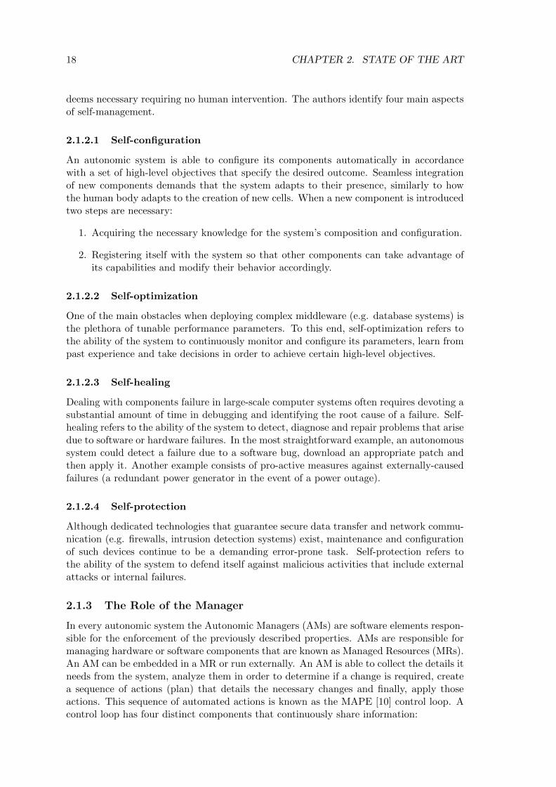
In every autonomic system the Autonomic Managers (AMs) are software elements respon-sible for the enforcement of the previously described properties. AMs are responsible formanaging hardware or software components that are known as Managed Resources (MRs).An AM can be embedded in a MR or run externally. An AM is able to collect the details itneeds from the system, analyze them in order to determine if a change is required, createa sequence of actions (plan) that details the necessary changes and finally, apply thoseactions. This sequence of automated actions is known as the MAPE [10] control loop. Acontrol loop has four distinct components that continuously share information:
2.2. CLOUD COMPUTING 19
• Monitor function: collects, aggregates and filters all information collected from anMR. This information may refer to topology, metrics or configuration properties thatcan either vary continuously through time or be static.
• Analyse function: provides the ability to learn about the environment and determineswhether a change is necessary, for example when a policy is being violated.
• Plan function: details steps that are required in order to achieve goals and objectivesaccording to defined policies. Once the appropriate plan is generated it is passed tothe execute function.
• Execute function: schedules and performs the necessary changes to the system.
A representation of the MAPE loop is shown in Figure 2.1.
ExecuteMonitor
PlanAnalyze
Knowledge
Managed Resource
Figure 2.1 – The MAPE control loop
2.2 Cloud Computing
This section briefly introduces the basic notions behind cloud computing, a computingparadigm that extends the ideas of autonomic computing and pairs them with a businessmodel that allows users to provision resources depending on their demands. First themain principles behind cloud computing are outlined. A description of the cloud maincharacteristics and the available service models follows.
2.2.1 What is Cloud Computing?
Cloud computing emerged as the new paradigm which shifts the location of a comput-ing infrastructure to the network, aiming to reduce hardware and software managementcosts [11].
The entity that provides users with on-demand resources is known as service provider.Many definitions have emerged over the years, however until today no standard definitionsexist. In this thesis we rely on the NIST definition presented in [12]:
Definition 1 Cloud computing is a model for enabling ubiquitous, convenient, on-demand network access to a shared pool of configurable computing resources (e.g. networks,servers, storage, applications, and services) that can be rapidly provisioned and releasedwith minimal management effort or service provider interaction.
In order to regulate the terms of providing access to cloud resources, the concept of ServiceLevel Agreement between the provider and the customers was introduced [4]. In thecontext of cloud computing customers are referred to as tenants.

20 CHAPTER 2. STATE OF THE ART
Definition 2 A Service Level Agreement (SLA) is a contract that specifies theservice guarantees expected by the tenants, the payment to the provider, and potentialpenalties when the guarantees are not met.
2.2.2 Characteristics
According to [12] the main characteristics of cloud computing are: broad network ac-cess, on demand self-service, resource pooling, elasticity and measured service.
• Broad network access: Cloud services are usually available through the Internet ora local area network and thus can be accessed from any device with access to thenetwork (e.g. smartphones, tablets, laptops, etc).
• On-demand self-service: Tenants can provision resources automatically without theneed for a personal negotiation of the terms with the cloud provider. Providers offerdedicated APIs in order to serve this purpose.
• Resource pooling : Computing resources can serve multiple tenants simultaneouslywith different physical and virtual demands adopting a multi-tenant model. In thismodel, tenants are oblivious about the exact location in which the provisioned re-sources are located.
• Elasticity : Tenants can automatically provision or release new resources dependingon computational demand. Theoretically, the resources that a tenant can provisionare unlimited.
• Measured service: Tenants and the provider can monitor and control resource usagethrough dedicated mechanisms. The same mechanisms can be used by the tenantsin order to check whether the terms defined in the SLA are respected.
2.2.3 Service Models
According to [13] the services that are available in cloud computing are categorized inthree models: Infrastructure as a Service (IaaS), Platform as a Service (PaaS)and Software as a Service (SaaS). The contributions presented in this thesis weredeveloped on a cloud infrastructure using the IaaS service model.
2.2.3.1 IaaS
IaaS offers tenants the capability to provision virtual resources (e.g. processing in the formof virtual machines, storage, networks) without worrying about the underlying physicalinfrastructure. Although the IaaS cloud model essentially offers the provisioning of anode-based infrastructure, the authors in [14] define two different layers of abstractionin the IaaS cloud model: Hardware as a Service (HWaaS) and Operating System as aService (OSaaS). In HWaaS the tenant is free to install arbitrary software, includingthe OS, while he is responsible for managing the whole software stack. In HWaaS theprovider is only accountable for providing the hardware resources. In OSaaS the tenantsare offered a fully managed OS including the underlying hardware resources (essentiallythe whole environment is perceived as a single compute node). Tenants can deploy theirapplication through the interplay of OS processes. The contributions presented in thisthesis target both HWaaS and OSaaS IaaS clouds. Known examples of IaaS HWaaSpublic clouds include: Amazon Elastic Cloud (EC2) [15], Google Compute Engine [16]
2.2. CLOUD COMPUTING 21
and OVH public cloud [17]. VMware vCloud [18] is a known example of IaaS HWaaSprivate cloud. Furthermore, a number of open source cloud management systems havebeen developed over the course of the last few years in order to enable the creation ofprivate clouds (described later in Section 2.2.4). Prominent examples in this category are:Eucalyptus [19], Nimbus [20], OpenNebula [21] and OpenStack [22].
2.2.3.2 PaaS
PaaS offers tenants the capability to deploy their own applications as long as they werecreated using programming languages and libraries supported by the provider. This modelallows tenants to focus on application development instead of other time consuming taskssuch as managing, deploying and scaling their run-time environment, depending on compu-tational load. Major PaaS systems include Google App Engine [23], Microsoft Azure [24]and Amazon Web Services [15] which are suitable for developing and deploying web ap-plications.
2.2.3.3 SaaS
SaaS offers tenants the capability of using the provider’s cloud hosted applications throughdedicated APIs. The applications are managed and configured by the provider althoughtenants might have access to limited user-related configuration settings. Prominent exam-ples in this category include: Gmail [25], Google calendar [25] and iCloud [26].
2.2.3.4 Main IaaS Systems
A lot of work in the past was focused on designing and implementing IaaS cloud systems.Tenants are provided with virtualized resources (in the form of Virtual Machines VMs– or containers) and a management system that allows them to manage their resourcesvirtualization technologies like KVM [27], Xen [28] and VMware ESX/ESXi [29] are thebuilding blocks that facilitate server virtualization and efficient resource utilisation. Lately,a trend towards containerization of IaaS cloud systems (e.g. Google Kubernetes [30]) hasbeen observed.
As stated in [31] the core of an IaaS cloud management system is the so called cloud-OS. The cloud OS is responsible for managing the provisioning of the virtual resourcesaccording to the need of the tenant services that are hosted in the cloud. As an exampleof a cloud OS, we present OpenStack [32], a mainstream IaaS management system thatwe used in order to develop our prototype.
OpenStack is an open source cloud management system that allows tenants to pro-vision resources within specific limits set by the cloud administrator. Tenants can view,create and manage their resources either by a dedicated web graphical interface (Hori-zon) or through command line clients that interact with each one of OpenStack’s services.OpenStack operates in a fully centralized manner with one node acting as a controller.The controller accepts user VM life cycle commands and delegates them to a pool ofcompute nodes. Upon receiving a command from the cloud controller, a compute nodeenforces it by interacting with the hypervisor. The controller node hosts a plethora ofthe main services delivered by OpenStack such as: Nova (manager of the VMs lifecycle),Neutron (network connectivity manager), Glance (VM disk image manager) and Keystone(mapping of tenants to services that they can access). Nova and Neutron are also installedon each compute node in order to provide VM interconnectivity and enforce user decisionregarding VMs lifecycle. Compute nodes periodically report back to the cloud controller

22 CHAPTER 2. STATE OF THE ART
their available resources (processing, memory, storage) and the state of the deployed VMs(e.g. network connectivity, lifecycle events). OpenStack offers a limited set of integra-tion tools for other public APIs (namely Amazon EC2 and Google Compute Engine). Arepresentation of OpenStack’s modular architecture can be found in Figure 2.2.
Controller Node
Nova Neutron Glance CinderSwift
Compute Networking ImageObjectstore Volume
HorizonDashboard Key
stone
Identityservice
NovaCompute
NeutronN/W
VM VMVM
NovaCompute
NeutronN/W
VM VMVM
Tenant network
Compute Node Compute Node
Management Network
External Network
Figure 2.2 – The OpenStack architecture
2.2.4 Deployment Models
There are four distinguishable cloud deployment models: Private, Public, Communityand Hybrid clouds.
• Private cloud : The cloud infrastructure is deployed on compute, storage and networksystems that belong to a single organization. A private cloud can be managed eitherby the organization or a third party entity and its usage does not exceed the scopeof the organization.
• Public cloud : The cloud infrastructure is available for provisioning for everyone onthe Internet. It is typically owned and managed by a cloud provider that allowscustomers (tenants) to request resources without having to deal with the burden ofmanaging them. As a result tenants are only charged for what they use, in accordancewith the pay-as-you-go model.
• Community cloud : The cloud infrastructure is dedicated to a specific communityor organizations that share a set of policies (i.e. security concerns, mission, andcompliance requirements). Community cloud comes as a solution for distributingcosts between different organizations in contrast to each organization maintainingits own private cloud (e.g. scientists from different organizations that work on thesame project can use the same community cloud). In contrast to public clouds accessto community clouds is restricted only to members of the community or organization.They can be managed by one or several organizations of the community. Communityclouds can be perceived as a specific category of private clouds.

2.2. CLOUD COMPUTING 23
• Hybrid cloud : The cloud infrastructure is a combination of two or more separatecloud infrastructures (private, public or community) that remain individual entities.The entities are bound together by a standardized agreement that allows data andapplication sharing.
In this thesis we developed a prototype considering a private cloud although the pro-posed framework can be integrated in both public and community clouds as well.
2.2.5 Dynamic Events in Iaas Clouds and Cloud Adaptation
Cloud environments are based on an elastic, highly scalable model that allows tenants toprovision resources (e.g. VMs) with unprecedented ease. Furthermore tenants can chooseto deploy different services inside their provisioned VMs and expose them to other usersthrough the Internet, generating network traffic towards and from the cloud infrastructure.As a result, cloud environments become very dynamic, with frequent changes occuring atdifferent levels of the infrastructure. In this section we categorize the observed changes inthree categories: service-related, topology-related and traffic-related events.
2.2.5.1 Service-related Events
Service-related dynamic events include all changes in the applications deployed in the VMsof a single tenant. These changes can refer to addition (i.e. installation) of a new applica-tion or the removal of an existing one inside an already deployed VM. A reconfiguration ofan existing application resulting in additional features is also considered a service-relateddynamic event.
2.2.5.2 Topology-related Events
Topology-related events include all changes in the topology of a tenant’s virtual infras-tructure. The three main commands in a VM life cycle that constitute topology relateddynamic events are: VM creation, VM deletion and VM migration (seamlessly moving aVM between two physical nodes over local or wide area network). VM migration can beinterpreted as a combination of creation and deletion as when a VM is migrated betweentwo nodes a new copy of the VM is created in the destination node, while the old copyof the VM is deleted from the source node. Public cloud providers offer the possibilityof auto-scaling to their tenants in order to automate management of their application’scomputational load. Scaling decisions generate topology-related changes either by addingnew virtual machines (scaling out) or by deleting existing ones when the application’sload decreases (scaling in). Network reconfiguration events (e.g. changing a subnet’s ad-dress range, moving VMs between different subnets or creating/deleting subnets) are alsoconsidered topology-related changes.
2.2.5.3 Traffic-related Events
Often tenants deploy network-oriented applications in their cloud infrastructure. Depend-ing on the load of the deployed applications, different levels of network traffic are generatedtowards and from the virtual infrastructure. Any change in the tenant’s virtual infrastruc-ture incoming or outgoing traffic load is considered a traffic-related dynamic event. Publiccloud providers offer load-balancing solutions in order to handle the dynamic network loadand evenly distribute it to available resources. Load balancing decisions can also lead totopology-related changes when new VMs are started or shutdown.
24 CHAPTER 2. STATE OF THE ART
2.2.5.4 Summary
In this section, we described the three main categories of dynamic events that occur in acloud infrastructure. The security monitoring framework designed in this thesis addressesthe need for reconfiguration of monitoring devices in all three event categories. We nowcontinue with a description of virtualization technologies as the building block that enablescloud-computing.
2.3 Virtualization
This section gives a brief overview of infrastructure virtualization. Infrastructure virtu-alization can be decomposed in server virtualization and network virtualization. We firstpresent the main server virtualization components followed by the four dominant servervirtualization techniques. Finally, this section concludes with a description of networkvirtualization.
The first ones to define the notion of server virtualization where Popek and Goldbergin their paper ”Formal requirements for virtualizable third generation architectures” [33].According to [33], virtualization is a mechanism permitting the creation of Virtual Ma-chines which are essentially efficient, isolated duplicates of real machines.
2.3.1 Server Virtualization Components
In an IaaS infrastructure there are three main architectural layers: physical, hypervisorand virtual machine. We briefly describe each one:
• Physical : The physical machine provides the computational resources that are di-vided between virtual machines (VMs). Computational resources include CPUs,memory and devices (e.g. disk, NIC).
• Hypervisor : Originally known as the Virtual Machine Monitor, this component isresponsible for mediating the sharing of physical resources (e.g. CPU, memory) be-tween different co-located VMs that operate concurrently. The hypervisor is respon-sible for ensuring isolation between different VMs providing a dedicated environmentfor each one without impacting the others.
• Virtual Machine: A VM or guest is the workload running on top of the hypervisor.The VM is responsible for executing user applications and virtual appliances. EachVM is under the illusion that it is an autonomous unit with its own dedicated physicalresources. The VM is oblivious about the existence of multiple other consolidatedVMs on top of the hypervisor of the same physical machine.
The security monitoring framework designed in this thesis targets the virtual machinelayer. For extracting key information regarding the services hosted inside the monitoredVMs the hypervisor is leveraged.
2.3.2 Server Virtualization
There are different mechanisms that enable the creation of virtual machines each one pro-viding different features. Here we detail the four main ones: emulation, full virtualization,paravirtualization and OS-level virtualization. The contributions presented in this thesisapply to full virtualization and paravirtualization.

2.3. VIRTUALIZATION 25
2.3.2.1 Machine-Level Virtualization
2.3.2.1.1 Emulation Emulation is the first proposed technique to allow the system torun a software that mimics a specific set of physical resources. This mechanism was usedto enable the usage of console video games on personal desktop machines. In emulation,the assembly code of the guest is translated into host instructions, a technique known asbinary translation. A dedicated component, the emulator is responsible for performingthe translation and providing isolation between different guests. There are two differenttranslation techniques: static and dynamic. Static binary translation requires translatingall of the guest code into host code without executing it. Dynamic binary translation on theother hand offers at runtime emulation where emulators fetch, decode and execute guestinstructions in a loop. The main advantage of dynamic binary translation is that sincethe translation is happening on the fly, it can deal with self-modifying code. Although theperformance cost is evident, emulation is very flexible as any hardware can be emulatedfor a guest’s OS. Popular emulators include Bochs [34] and Qemu [35], which support awide number of guest architectures (x86, x86 64, MIPS, ARM, SPARC).
2.3.2.1.2 Full Virtualization Full system-wide virtualization delivers a virtual ma-chine with dedicated virtual devices, virtual processors and virtual memory. In full vir-tualization the hypervisor is responsible for providing isolation between VMs as well asmultiplexing on the hardware resources. This technique enables running VMs on top ofphysical hosts without the need to perform any alterations on the VM or the host OSkernel. In [33] the authors formalize the full-virtualization challenge as defining a virtualmachine monitor satisfying the following properties:
• Equivalence: The VM should be indistinguishable from the underlying hardware.
• Resource control: The VM should be in complete control of any virtualized resources.
• Efficiency: Most VM instructions should be executed directly on the underlying CPUwithout involving the hypervisor.
The two methods that make full virtualization possible are: binary translation andhardware acceleration. We discuss both of them.
Binary translation: This technique uses the native OS I/O device support whileoffering close to native CPU performance by executing as many CPU instructions as pos-sible on bare hardware [36]. When installed, a driver is loaded in the host OS kernel inorder to allow it’s user space component to gain access to the physical hardware whenrequired. The same driver is responsible for improving network performance for the vir-tualized guest.Non-virtualized instructions are detected using binary translation and arereplaced with new instructions that have the desired effect on the virtualized hardware.The main argument behind virtualization through binary translation is that no modifi-cations of either the guest or the host OS are required. Unfortunately, a non-negligibleperformance penalty is applied due to the need of performing binary translation and em-ulation of privileged CPU instructions. Full virtualization with binary translation can beinterpreted as a hybrid technique between emulation and virtualization. In contrast to em-ulation where each CPU instruction is emulated, full virtualization with binary translationallows for some CPU instructions to run directly on the hosts CPU. The most popular fullyvirtualized solutions using binary translation are: Qemu [35], VirtualBox [37], VMwareFusion and Workstation [38] [39].

26 CHAPTER 2. STATE OF THE ART
Hardware acceleration: In order to cope with the performance overhead intro-duced by binary translation and enable virtualization of physical hardware, Intel (resp.AMD) came up with the VT-x technology [40] (resp. AMD-V). With VT-x a new rootmode of operation is allowed in the CPU. Two new transitions are enabled: from the VMMto a guest a root to non-root transition (called VMEntry) and from the guest to VMMa non-root to root transition (called VMExit). Intel uses a new data structure to storeand manage information regarding when these transitions should be triggered, the virtualmachine control structure (VMCS). Typically a VMExit occurs when the VM attemptsto run a subset of privileged instructions. The VMCS data structure stores all necessaryinformation (instruction name, exit reason). This information is later used by the VMMfor executing the privileged instruction. The most popular solutions using hardware as-sisted virtualization are: KVM [27], VMware ESXi [29], Microsoft Hyper-V [41] and XenHardware Virtual Machine [42].
2.3.2.1.3 Paravirtualization In contrast to full virtualization which advocates forno modifications in the guest OS, paravirtualization requires the guest OS kernel to bemodified in order to replace non-virtualized instructions with hypercalls that communi-cate directly with the hypervisor. The hypervisor is responsible for exporting hypercallinterfaces for other sensitive kernel operations such as memory management and inter-rupt handling. Xen Project [28] has been the most prominent paravirualization solution.In Xen the processor and memory are virtualised using a modified Linux kernel. Themodified kernel is actually an administrative VM (called dom0) responsible for providingisolation between VMs, handling network, I/O and memory management for the guestVMs (domU). Dom0 is also in control of the guest VMs lifecycle and bares the responsi-bility for executing privileged instructions on behalf of the guest OS. The later is done byissuing hypercalls. Dom0 traps the latter and executes them either by translating themto native hardware instructions or using emulation. Xen operates based on a split drivermodel where the actual device drivers, called backend drivers, are located inside Dom0and each DomU implements an emulated device, called frontend driver. Every time aDomU issues a call to a driver the emulated part transfers the call to the actual driver inDom0 – hence the two drivers complementary operate as one. Although Xen is a promisingsolution for near native performance, its application is limited to open source OSes likeLinux or proprietary solutions which offer a customized Xen-compatible version.
2.3.2.1.4 Hypervisor Practices Emulation, full virtualization and paravirtualiza-tion can be combined. Typically, devices are fully emulated (for maintaining the use oflegacy drivers) or paravirtulized (for efficient multiplexing access on these devices fromdifferent VMs) while the CPU is fully virtualized. Modern hypervisors that adopt thistechnique are: KVM [27], Xen [28] and VMware Workstation [39].
2.3.2.2 OS-level Virtualization
Another solution, known as lightweight or OS-level virtualization [43], allows the OS kernelto perform virtualization at the system call interface, and create isolated environments thatshare the same kernel. These flexible, user-oriented isolated environments are known ascontainers. Containers have their own resources (e.g. file system, network connectivity,firewall, users, applications) that are managed by the shared OS kernel (responsible forproviding isolation). Since they all share the same kernel the performance overhead isminimal to none. Furthermore, a container can be migrated in the same way as a VM.

2.3. VIRTUALIZATION 27
Unfortunately, the main issue behind OS-level virtualization is that all containers in asingle physical machine are limited to the kernel of the host OS. This limits the number ofOSes to only the ones supported by the host’s kernel. LXC [44] and Docker [45] are someof the most prominent solutions in this category.
2.3.3 Network Virtualization and Network Management in IaaS Clouds
Network virtualization is one of the key aspects in an IaaS cloud environment. AssigningIP addresses to VMs, communication between VMs that belong to the same or differenttenants and finally communication between VMs and the outside world are some of theissues that need to be addressed from the network virtualization component of the IaaScloud management system. In this section we first present the mechanisms that materializenetwork virtualization and we continue with a discussion about network management inIaaS clouds focusing on OpenStack.
2.3.3.1 Network Virtualization
There are different solutions that enable network virtualization. Multi-protocol LabelSwitching [46] uses a ”label” appended to a packet in order to transport data insteadof using addresses. MPLS allows switches and other network devices to route packetsbased on a simplified label (as opposed to a long IP address). Hard VLANs allow a singlephysical network to be broken to multiple segments. By grouping hosts that are likely tocommunicate with each other to the same VLAN, one can reduce the amount of traffic thatneeds to be routed. Flat networking relies on the ethernet adapter of each compute node(which is configured as a bridge) in order to communicate with other hosts. With VLANtagging each packet belonging to a specific VLAN is assigned the same VLAN ID whilewith GRE encapsulation traffic is encapsulated with a unique tunnel ID per network (thetunnel ID is used in order to differentiate between networks). VLAN tagging and GREencapsulation both require a virtual switch in order to perform the tagging (respectivelyencapsulation) while flat networking does not require a virtual switch.
However these solutions lack a single unifying abstraction that can be leveraged toconfigure the network in a global manner. A solution to this empedement that pro-vides dynamic centrally-controlled network management is software defined networking(SDN) [47]. In this section we mainly focus on SDN.
Software defined networking [47] emerged as a paradigm in an effort to break thevertical integration of the control and the data plane in a network. It separates a network’scontrol logic from the underlying physical routers and switches which are now simpleforwarding devices. The control logic is implemented in a centralized controller allowingfor a more simplified policy enforcement and network reconfiguration. Although SDNs arelogically centralized, the need for a scalable, reliable solution that guarantees adequateperformance does not allow for a physically centralized approach. The separation betweenthe control and the data plane is feasible by creating a strictly defined programmableinterface (API) between the switches and the SDN controller. The most notable exampleof such API is OpenFlow [48]. In each OpenFlow switch flow tables of packet-handlingrules are stored. Each rule matches a subset of the traffic and performs certain actions(dropping, forwarding, modifying) on the matched subset. The rules are installed on theswitches by the controller and depending on their content a switch can behave like a router,switch, firewall or in general a middlebox. A switch can communicate with the controllerthrough a secure channel using the OpenFlow protocol which defines the set of messagesthat can be exchanged between these two entities. Traffic handling rules can be installed

28 CHAPTER 2. STATE OF THE ART
on the switches either proactively or reactively, when a packet arrives. A representationof the SDN architecture can be found in Figure2.3.
SDN Controller
InfrastructureLayer
ControlLayer
ApplicationLayer
SouthboundAPI (e.g OpenFlow)
Virtual Switch
VM VM
Virtual Switch
VM VM
Figure 2.3 – The SDN architecture
Although OpenFlow is the most widely accepted and deployed API for SDNs thereare several other solutions such as ForCES [49] and POF [50]. The controller provides aprogrammatic interface to the network that can be used to execute management tasks aswell as offer new functionalities. It essentially enables the SDN model to be applied on awide range of hardware devices (e.g. wireless, wired). A wide range of available controllersexist such as Nox [51], OpenDaylight [52] and Floodlight [53].
Making network virtualization a consolidated technology requires multiple logical net-works to be able to share the same OpenFlow networking infrastructure. FlowVisor [54]was one of the early solutions towards that direction. It enables slicing a data plane basedon off-the-shelf OpenFlow compatible switches, making the coexistence of multiple net-works possible. The authors propose five slicing dimensions: bandwidth, topology, traffic,forwarding tables and device CPU. Each slice can have its own controller allowing multiplecontrollers to inhabit the same physical infrastructure. Each controller can only operateon its own slice and gets its own flow tables in the switches.
FlowN [55] offers a solution analogous to container virtualization (i.e. a lightweightvirtualization approach). In contrast with FlowVisor [54], it deploys a unique sharedcontroller platform that can be used to manage multiple domains in a cloud environment.A single shared controller platform enables management of different network domains. Itoffers complete control over a virtual network to each tenant and it allows them to developany application on top of the shared controller.
Network virtualization platform (NVP) from VMware (as part of the NSX [56] prod-uct) provides the necessary abstractions for the creation of independent networks (eachone with different service model and topology). No knowledge about the underlying net-work topology or state of the forwarding devices is required as tenants simply providetheir desired network configuration (e.g. addressing architecture). NVP is responsiblefor translating tenant requirements to low-level instruction sets that are later on installedon the forwarding devices. A cluster of SDN controllers is used in order to modify the

2.4. SECURITY THREATS 29
flow tables on the switches. NVP was designed to address challenges in large-scale multi-tenant environments that are not supported by the previously described solutions (e.g.migrating an information system to the cloud without the need of modifying the networkconfiguration). A similar solution is SDN VE [57] from IBM based on OpenDaylight.
2.3.3.2 Network Management in Iaas Clouds
Network virtualization delivers compute-related options (create, delete) to network man-agement. Network objects (networks, subnets, ports, routers, etc) can be created, deletedand reconfigured programmatically without the need of reconfiguring the underlying hard-ware infrastructure. The underlying hardware infrastructure is treated as a pool of trans-port resources that can be consumed on demand. Tenants can create private networks(i.e. tenant networks) and choose their own IP address scheme, which can overlap withIP addresses chosen by other tenants. Depending on the type of the tenant network (flat,VLAN, GRE) different communication capabilities are offered to the instances attachedto these networks.
The networking component of an IaaS cloud management system is responsible formapping tenant-defined network concepts to existing physical networks in a data cen-ter. Essentially the network component performs the following functionalities: assign IPaddresses to VMs, facilitating communication between VMs that belong to the same ordifferent tenants and finally providing VMs with outside-world connectivity.
In OpenStack, Neutron is responsible for managing different tenant networks and offer-ing a full set of networking services (routing, switching, load-balancing, etc) to provisionedVMs. Neutron is composed of agents (e.g. DHCP agent, L3 routing agent, etc) that pro-vide different types of networking services to provisioned VMs. Neutron creates threedifferent networks in a standard cloud deployment:
1. Management network: used for communication between the OpenStack components.This network is only reached from within the datacenter.
2. Tenant networks: used for communication between VMs in the cloud. The config-uration of these networks depends on the networking choices made by the differenttenants.
3. External network: used to provide internet connectivity to VMs hosted in the cloud.
On each compute node a virtual bridge is created by a dedicated Neutron plugin (calledML2 plugin) which is locally installed on each node. VMs are connected to networksthrough virtual ports on the ML2-created bridge. The ML2 plugin is also responsible forsegregating network traffic between VMs on a per tenant basis. This can be achievedeither through VLAN tagging (all VMs that belong to the same network are assigned thesame tag) or GRE encapsulation.
2.4 Security Threats
In this section we detail some of the known attacks against information systems and cloudenvironments.
2.4.1 Security Threats in Information Systems
Although one of the most common ways of executing cyber attacks is through the network(i.e. either the Internet or a local area network), the attackers often target different areas

30 CHAPTER 2. STATE OF THE ART
in an information system. Here we list the most common threats depending on their targetlevel. Before presenting each threat category in detail, we present a high level overviewof the vulnerability classes that attackers can exploit. In general, missing validation ofinputs in an application can create an entry point for attacks (listed below). Furthermore,lack of access control (i.e. through authentication mechanisms) can allow an attacker togain unauthorized privileged access.
2.4.1.1 Application Level
Application-level threats are abilities of an attacker to exploit vulnerabilities in the soft-ware of one or more applications running in an information system.
One of the most common application-level attack is SQL injection [58] against DatabaseManagement Systems (DBMS). An SQL injection attack occurs when a malicious entityon the client side manages to insert an SQL query via input data to the application. Thisis usually possible due to lacks of input validation. The impact of the injection may varydepending on the skills and imagination of the attacker. Usually, through an SQL exploitthe attacker can gain access to sensitive data inside the database, modify them (insert ordelete or update) or even retrieve the contents of a file present in the system. He can alsoshutdown the DBMS by issuing administrative commands and sometimes even executecommands outside the DBMS.
Another type of an injection attack is cross-site scripting (XSS) [59] when the attackermanages to insert malicious code in a trusted website. Cross-site scripting exploits theabsence of validation of user input. The malicious code could be in the form of a JavaScriptsegment or any other code that the browser can execute. When a different user accessesthis website she will execute the script thinking that it comes from a trusted source, givingthe attacker access to cookies, session tokens or other sensitive information retrieved bythe browser on behalf of the infected website. In a more severe scenario the attacker mighteven redirect the end user to web content under his control. An XSS attack can eitherbe stored (the malicious script permanently resides on the target server) or reflected (thescript is reflected off the web server – for example in an error message).
A buffer overflow [60] generally occurs when an application attempts to store datain a buffer and the stored data exceeds the buffer’s limits. Buffer overflows are possiblebecause of badly validated input on the application’s side. Writing in an unauthorizedpart of the memory might lead to corrupted data, application crashes or even maliciouscode execution. Buffer overflows are often used as entry points for the attacker in orderto inject malicious code segment into the host’s memory and then execute it by jumpingto the right memory address. Another alternative for malicious code injection is formatstring attacks [61]. Format String Attacks (FSA) are used in order to leak informationsuch as pointer addresses. After a successful FSA, normally a return oriented programmingexploit is used. Return oriented programming allows the attacker to use short sequences ofinstructions that already exist in a target program in order to introduce arbitrary behavior.
2.4.1.2 Network Level
In the network-level threat category we describe attacks that target communications oflayer 3 and above in an information system.
Network-level impersonation occurs when an attacker masks his true identity or triesto impersonate another computer in network communications. Operating systems use theIP address of a packet to validate its source. An attacker can create an IP packet witha header that contains a false sender’s address, a technique known as IP spoofing [62].
2.4. SECURITY THREATS 31
This technique, combined with TCP protocol specifications (i.e. the sequence and ac-knowledgement numbers included in a TCP header) can lead to session hijacking. Theattacker predicts the sequence number and creates a false session with the victim who inturn thinks that he is communicating with the legitimate host.
Denial of Service (DoS) attacks aim at exhausting the computing and network resourcesof an information system. The way these attacks operate is by sending a victim a streamof packets that swamps its network or processing capacity, denying access to its normalclients. One of the methods employed is SYN flooding [63], in which the attacker sendsclient requests to the victim’s server. SYN flooding attacks target hosts that run TCPserver processes and exploit the state retention of the TCP protocol after a SYN packet hasbeen received. Their goal is to overload the server with half-established connections anddisturb normal operations. Both IP spoofing and SYN flooding are common techniques forlaunching a denial of service attack and preventing users from accessing a network service.In the event of a server being protected against SYN flood attacks, a denial of service canstill be possible if the server in question is too slow in serving flooding requests (the attackersimply overloads the server). Finally, as the name indicates, a man-in-the-middle attackrefers to a state where the attacker is able to actively monitor, capture and control thenetwork packets exchanged between two communicating entities. Sophisticated versionsof man-in-the-middle attacks include attempts against TLS-based communications wherethe attackers are able to falsely impersonate legitimate users [64].
Domain Name Servers (DNS) are essential parts of the network infrastructure that mapdomain names to IP addresses redirecting requests to the appropriate location. Attackerstarget DNS systems in their effort to redirect legitimate requests to malicious websitesunder their control. One of the most common techniques to achieve that is DNS cachepoisoning. DNS cache poisoning exploits a vulnerability in the DNS protocol [65] in orderto replace legitimate resolution results with flawed ones that include the attacker’s website.
Depending on the type of services hosted in an information system attackers use dif-ferent exploitation techniques. Identification of the type of hosted services is a necessarypreliminary step in most exploitation attempts. A common way for an attacker to identifynetwork services hosted in an information system or probe a specific server for open ports,is port scanning [66]. The standard way to perform a port scan is to launch a process thatsends client requests to a range of ports in a particular server (vertical port scan) or to aspecific port on several hosts (horizontal port scan). Depending on the type of the requestthere are different port scan categories at the TCP level. Application fingerprinting, wherean attacker looks for a reply that matches a particular vulnerable version of an applicationis also a common technique used to identify the type of hosted service.
2.4.1.3 Operating System Level
All user applications in an information system rely on the integrity of the kernel and coresystem utilities. Therefore, a possible compromise of any of these two parts can resultin a complete lack of trust in the system as a whole. One of the most common attacksagainst a system’s kernel is a rootkit installation. Rootkits are pieces of software that allowattackers to modify a host’s software, usually causing it to hide their presence from thehost’s legitimate administrators. A sophisticated rootkit is often able to alter the kernel’sfunctionality so that no user applications that run in the infected system can be trustedto produce accurate results (including rootkit detectors). Rootkits usually come with adedicated backdoor so the attacker can gain and maintain access to the compromised host.Backdoors usually create secure SSH connections such that the communication between
32 CHAPTER 2. STATE OF THE ART
the attacker and the compromised machine cannot be analysed by Intrusion DetectionSystems or other network monitoring tools.
2.4.1.4 Summary
In this section we have described security threats targeting traditional information systems.The described attacks could also target applications running inside virtual machines in anoutsourced infrastructure. We continue with a description of cloud specific security threatsand a classification based on their target.
2.4.2 Security Threats in Cloud Environments
In a cloud environment security concerns two different actors. First, tenants are concernedwith the security of their outsourced assets, especially if they are exposed to the Internet.Second, the provider is also concerned about the security of the underlying infrastructureespecially when he has no insight regarding the hosted applications and their workload. Inthis section we focus on security threats originating from corrupted tenants against otherlegitimate tenants and their resources, threats against the provider’s infrastructure andtheir origin as well as threats towards the provider’s API.
2.4.2.1 Threats against tenants and based on shared resources
One of the key elements of a cloud infrastructure is multi-tenancy (i.e. multiplexing virtualmachines that belong to different tenants on the same physical hardware). Although thismaximizes efficiency for the cloud provider’s resources, it also offers the possibility thata tenant’s VM can be located in the same physical machine as a malicious VM. This inturn engenders a new threat: breaking the resource isolation provided by the hypervisorand the hardware and gaining access to unauthorized data or disturbing the operation oflegitimate VMs.
One of the most prominent attacks that illustrates this threat is the side channel attackwhere an adversary with a colocated VM gains access to information belonging to otherVMs (e.g. passwords, cryptographic keys). In [67] the attackers used shared CPU cachesas side channels in order to extract sensitive infomation from a colocated VM.
Another technique that exploits VM colocation is DoS attacks against shared resources.A malicious VM is excessively consuming shared computing resources (CPU time, memory,I/O bandwidth) disallowing legitimate VMs from completing their tasks.
2.4.2.2 Provider Infrastructure
In an IaaS cloud environment 2.2.3.1 each VM is under the illusion that it runs on its ownhardware (i.e. CPU, memory, NIC, storage). This illusion is created by the hypervisor,which is responsible for allocating resources for each VM, handling sensitive instructionsissued by VMs and finally managing VM lifecycle 2.3. In this section we discuss securitythreats targeting the hypervisor, as a core component of the provider’s infrastructure.
An attacker targeting the hypervisor might be able to execute malware from differentruntime spaces inside the cloud infrastructure. Each runtime space comes with differentprivileges. We list the runtime spaces in increasing order of privilege level (also the orderin difficulty to exploit).
• Guest VM User-Space: This runtime space is the easiest one to obtain especiallyin an IaaS environment. Although, attempts to run privileged instructions could

2.5. SECURITY MONITORING 33
lead to an exception, an attacker can run any type of exploit. In [68] the attackermanages to break out from a guest by exploiting a missing check in the QEMU-KVMuser-space driver.
• Guest VM Kernel-Space: Since in an IaaS cloud environment tenants can run an OSof their choice, an attacker can provision some VMs, run an already tampered OSand use the malicious guest’s kernel to launch an attack to the hypervisor. In [69]an attack to the hypervisor implements a malicious para-virtualized front-end driverand exploits a vulnerability in the back-end driver.
• Hypervisor Host OS: One of the most desirable runtime spaces for an attacker is theone of the host OS as the privileges granted are very high. For example, KVM as apart of the Linux kernel, provides an entry point for attackers that have local useraccess to the host machine, exploiting a flaw in KVM.
Customers in public clouds manage their resources through dedicated web control in-terfaces. Moreover, cloud providers also manage the operation of the cloud system throughdedicated interfaces that are often accessible through the Internet. A successful attack ona control interface could grant the attacker complete access to a victim’s account alongwith all the data stored in it, or even worse to the whole cloud infrastructure when theprovider’s interface is compromised. In [70] attacks towards cloud management interfacesare considered extremely high risk and in [71] the authors prove that the web interfaces oftwo known public and private cloud systems (Amazon’s EC2 and Eucalyptus) are suscepti-ble to signature wrapping attacks. In a signature wrapping attack, the attacker can modifya message signed by a legitimate signature, and trick the web service into processing itsmessage as if it was legitimate.
2.4.3 Summary
In summary, traditional information systems as well as cloud environments face multiplesecurity threats originating from different privilege levels in the infrastructure. In an IaaScloud environment the attack surface is expanded with the addition of the hypervisor,as the building block of a cloud infrastructure, as well as the web-exposed managementAPI. In order to successfully detect attacks a security monitoring framework is needed.We continue our discussion with a detailed description of security monitoring frameworksboth for traditional information systems and cloud environments.
2.5 Security Monitoring
Information systems face continuous threats at different levels of their infrastructure. Anattacker can gain access to the system by exploiting a software vulnerability and thus beable to modify both the OS kernel and critical system utilities. In order to detect suchactivities, a security monitoring framework is necessary. A security monitoring frameworkconsists of the appropriate detection mechanisms required to diagnose when an informationsystem has been compromised and inform the administrator in the form of specialisedmessages (called alerts).
2.5.1 What is Security Monitoring?
According to [72]:

34 CHAPTER 2. STATE OF THE ART
Definition 3 Security Monitoring is the collection, analysis, and escalation of indica-tions and warnings to detect and respond to intrusions.
Due to the diverse nature of applications hosted in an information system, a security mon-itoring framework requires multiple components that monitor different parts of the systemin order to maintain situational awareness of all hosted applications. Figure 2.4 depicts aninformation system with different security devices: firewalls, antiviruses, network-basedIDS.
Externaltraffic
Mirroredtraffic
Network Intrusion Detection System Antivirus
Antivirus
Firewall
NetworkAnalyzer
Figure 2.4 – Information system with different security devices contributing to securitymonitoring
In the following sections we discuss some of the core components embedded in modernsecurity monitoring frameworks focusing primarily on Intrusion Detection Systems (IDS)and Firewalls as the contributions presented in this thesis focus on these two components.
2.5.1.1 Main Components
Several tools are available for mitigating malware threats in an information system. Welist the most common ones along with their typical features.
• Antivirus: Most antivirus solutions provide capabilities such as scanning criticalsystem components (startup files, boot records), real-time scanning of files that aredownloaded, opened or executed, sandboxed dynamic monitoring of running appli-cations and identifying common types of malware (viruses, worms, backdoors, etc).Commercial solutions include Kaspersky Security Scan [73], AVG antivirus [74] andPanda Protection [75].
• Router: Typically a router uses a set of traffic management rules that is knownas an access control list. Routers are normally deployed in front and at the core ofan information system’s firewall and perform some traffic mitigation such as ingressand egress filtering. Commercial solutions include: Cisco ASR 1000 Series [76] andJuniper MX Series [77].
• Access Control Systems: Normally access control systems are concerned withregulating the users attempts to access specific resources in an information system.Information systems apply access controls at different levels of their infrastructure(e.g. an OS regulating access to files, or an authentication server described below).
• Virtual Private Network (VPN): VPN allows users to access an organization’sprivate network remotely. It offers traffic encryption between two connection points
2.5. SECURITY MONITORING 35
through a variety of supported protocols (TLS [78], IPsec [79], DTLS [80]). Examplesof VPN service providers include: VPN Express[81] and VyPR VPN [82]
• Authentication Server: A server that is used to authenticate users or applicationsthrough the network using a set of credentials (e.g. username and password). Au-thentication servers support a variety of protocols. Notable example of this categoryis the LDAP protocol [83] and Kerberos [84] protocol.
• Log Collectors: In order to facilitate the collection and analysis of events of inter-est, log collectors are necessary for every information system. Depending on the levelof desired system-wide visibility, different time intervals for the collection of logs canbe defined. Due to high diversity between event sources (i.e. applications, system,security devices) most software solutions are able to gather and unify informationfrom different sources and different formats. In a cloud environment log collectionis of critical importance as it allows tenants to gain insight into resources utiliza-tion, application performance, security and operational health. Major public cloudsoffer customisable logging services such as CloudWatch [85] and Log Analytics [86].In traditional information systems a variety of log collection solutions exists (e.g.rsyslog [87], LogStash [88]).
2.5.1.2 Intrusion Detection Systems
Intrusion detection systems are usually at the core of a security monitoring framework.Their main purpose is to detect security breaches in an information system before theyinflict widespread damage. An IDS is composed of three main stages: data collection,processing and reporting. The core detection feature is implemented in the processingstage.
2.5.1.3 What is an IDS?
According to [89]:
Definition 4 Intrusion detection is the process of monitoring the events occurring ina computer system or network and analyzing them for signs of possible incidents, whichare violations or imminent threats of violation of computer security policies, acceptable usepolicies, or standard security practices.
Consequently, an Intrusion Detection System is software that automates the intrusiondetection process.
In the following section we describe the different types of IDSs according to theirdetection technique and we follow with a classification based on the embedded technology.
2.5.1.4 Types of IDSs
Most of the IDS technologies are based on one of the two following detection tech-niques [90], [91]. We describe each one along with observed advantages and pitfalls.
• Signature-based: Signature-based IDSs compare observed events against a list ofa priori known signatures in order to identify possible security breaches. A signa-ture is generally a pattern that corresponds to a registered attack. Signature-baseddetection is very effective at identifying known threats and is the simplest form of

36 CHAPTER 2. STATE OF THE ART
detection. A signature-based IDS compares the current unit of activity (e.g. net-work packet, file content) to the list of signatures using string comparison. Unfortu-nately, signature-based detection is largely ineffective when dealing with previouslyunknown attacks, attacks that are composed by multiple events or attacks that useevasion techniques [92]. Known examples of signature based IDSs include Snort [93],Suricata [94] and Sagan [95].
• Anomaly-based: Anomaly-based IDSs compare a profile of activity that has beenestablished as normal with observed events and attempt to identify significant de-viations. Each deviation is considered an anomaly. A normal profile is created byobserving the monitored system for a period of time-called training period (e.g. fora given network http activity composes 15% of the observed traffic) and can bestatic (the profile remains unchanged) or dynamic (the profile is updated at spe-cific time intervals). Depending on the methodology used to create the normalprofile anomaly-based IDSs are either statistical-, knowledge- or machine-learning-based [92]. Statistical-based IDSs represent the behavior of the analysed systemfrom a random view point, while knowledge-based IDSs try to capture the system’sbehavior based on system data. Finally machine learning-based IDSs establish amodel that allows for pattern categorization.
One of the main advantages of an anomaly-based IDS is that it can be very effectivewhen dealing with previously unknown attacks. Unfortunately, anomaly-based IDSssuffer from many false positives when benign activity, that deviates significantly fromthe normal profile, is considered an anomaly. This phenomenon is amplified when themonitored information system is very dynamic. Known examples of anomaly-basedIDSs include Bro [96], Stealthwatch [97] and Cisco NGIPS [98].
According to [99] IDS technologies are divided in two categories depending on the typeof events that they monitor and the ways in which they are deployed:
• Network-based (NIDS): NIDSs monitor network traffic (i.e. packets) for a par-ticular network or segments of a network and analyze network protocol activity orpacket payload in order to detect suspicious events or attacks. The most commonapproach for deploying an NIDS is at a boundary between networks, in proximityto border firewalls or other security devices. A specific category of NIDS is wirelessIDSs, which monitor only wireless network traffic and analyze wireless network pro-tocols for identifying suspicious activity. In contrast to other NIDS which focus onpacket payload analysis, wireless NIDSs focus on anomalies in wireless protocols.
• Host-based (HIDS): HIDSs monitor the events occurring in a single host for sus-picious activity. An HIDS can monitor network traffic, system logs, application ac-tivity, process list and file access in a particular host. HIDSs are typically deployedon critical hosts that contain sensitive information.
We have described the main IDS categories based on the mechanism used for detectionand the way they are deployed. The work done in this thesis focuses on network-basedIDSs. We now discuss the second main security component that has been addressed inthis thesis: the firewall.
2.5.1.5 Firewalls
This section focuses on a different security component, the firewall.
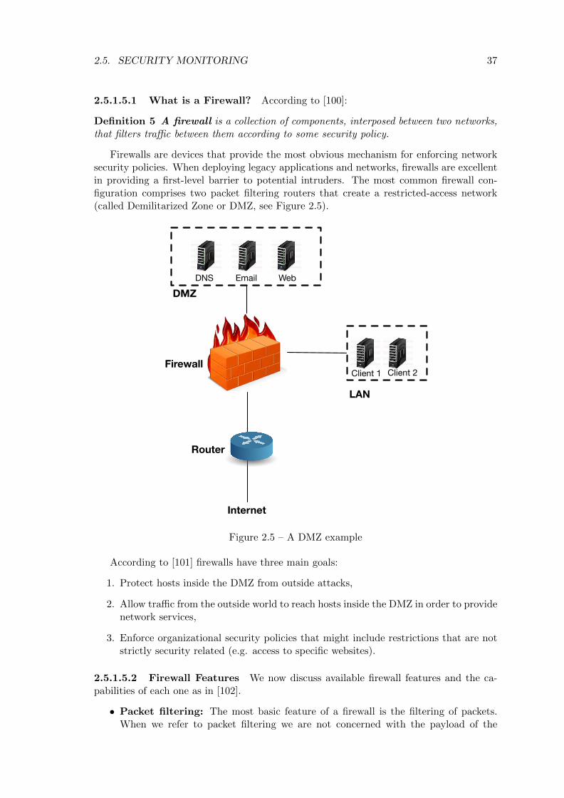
2.5. SECURITY MONITORING 37
2.5.1.5.1 What is a Firewall? According to [100]:
Definition 5 A firewall is a collection of components, interposed between two networks,that filters traffic between them according to some security policy.
Firewalls are devices that provide the most obvious mechanism for enforcing networksecurity policies. When deploying legacy applications and networks, firewalls are excellentin providing a first-level barrier to potential intruders. The most common firewall con-figuration comprises two packet filtering routers that create a restricted-access network(called Demilitarized Zone or DMZ, see Figure 2.5).
DNS Email WebDMZ
LAN
Client 1 Client 2
Router
Firewall
Internet
Figure 2.5 – A DMZ example
According to [101] firewalls have three main goals:
1. Protect hosts inside the DMZ from outside attacks,
2. Allow traffic from the outside world to reach hosts inside the DMZ in order to providenetwork services,
3. Enforce organizational security policies that might include restrictions that are notstrictly security related (e.g. access to specific websites).
2.5.1.5.2 Firewall Features We now discuss available firewall features and the ca-pabilities of each one as in [102].
• Packet filtering: The most basic feature of a firewall is the filtering of packets.When we refer to packet filtering we are not concerned with the payload of the

38 CHAPTER 2. STATE OF THE ART
network packets but with the information stored in their headers. The mechanismof packet filtering is controlled by a set of directives which is known as ruleset. Thesimplest form of a packet filtering device is a network router equipped with accesscontrol lists.
• Stateful inspection: This functionality essentially improves packet filtering bymaintaining a table of connections state and blocking packets that deviate from theexpected state according to a given protocol.
• Application-level: In order to extend and improve stateful inspection, statefulprotocol analysis was created. With this mechanism a basic intrusion detectionengine is added in order to analyse protocols at the application layer. The IDSengine compares observed traffic with vendor-created benign profiles and is able toallow or deny access based on how an application is behaving over the network.
• Application-proxy gateways: A firewall which acts as an application-proxy gate-way contains a proxy agent that acts as an intermediary between different hoststhat want to communicate with each other. If the communication is allowed thentwo separate connections are created (client-to-proxy and proxy-to-server) while theproxy remains transparent to both hosts. Much like an application-level firewall theproxy can inspect and filter the content of traffic.
• Virtual private networking (VPN): A common requirement for firewalls is toencrypt and decrypt network traffic between the protected network (DMZ) and theoutside world. This is done by adding a VPN functionality to the firewall. As withother advanced firewall functionalities (besides simple header-based packet filtering)a trade-off between the functionality and the cost in terms of computational re-sources (CPU, memory) depending on the traffic volume and the type of requestedencryption, is introduced.
• Network access control: Another functionality for modern firewalls is controllingincoming connections based on the result of health checks performed on the computerof a remote user. This requires an agent that is controlled by the firewall to beinstalled in the user’s machine. This mechanism is typically used for authenticatingusers before granting them access to the network.
• Unified threat management: The combination of multiple features into a singlefirewall is done with the purpose of merging multiple security objectives into a singlesystem. This usually involves offering malware detection and eradication, suspiciousprobe identification and blocking along with traditional firewall capabilities. Unfor-tunately, the system’s requirements in terms of memory and CPU are significantlyincreased.
In this thesis, we address application-level firewalls and firewalls that provide statefultraffic inspection capabilities.
2.5.2 Security Monitoring in Cloud Environments
After presenting different components of a security monitoring framework we zoom in secu-rity monitoring frameworks tailored for cloud environments. As explained in Section 2.2.5cloud environments experience dynamic events in different levels of the infrastructure.Naturally, the occurring events engender changes for the security monitoring framework

2.5. SECURITY MONITORING 39
that requires its components to be automatically adapted to the new state. For example,when a VM is migrated from one compute node to another, the NIDS that is responsiblefor monitoring the traffic on the destination compute node needs to be reconfigured inorder to monitor the traffic for specific attacks against the services hosted in the migratedVM. Without reconfiguration, an attack could pass undetected, creating an entry pointfor the attacker and allowing him to compromise the cloud-hosted information system.
In this section we discuss cloud security monitoring solutions targeting either to theprovider infrastructure and its most critical components (e.g. hypervisor, host OS kernel)or to the tenant information system.
2.5.2.1 Provider Infrastructure Monitoring
This section presents security solutions that target the cloud provider’s infrastructure fo-cusing on the hypervisor and host OS kernel. The frameworks described in both categoriescould be considered as hypervisor or kernel IDS systems. The relationship between thehypervisor and the host OS kernel is depicted in Figure 2.6. In this picture the hypervisorruns as a kernel module while the VMs run in user space. Their virtual address space ismapped through the hypervisor to the host’s physical address space.
Hypervisor
VM
Host OS Kernel
Hardware
VM VM
Figure 2.6 – Hypervisor and host OS kernel
2.5.2.1.1 Hypervisor Integrity Checking Frameworks One of the trends in se-curing the hypervisor involves reducing the Trusted Code Base (TCB) [103] in many ofthe commercial hypervisors. Although, such a solution would limit the attack surface itwould not completely guarantee the integrity of all hypervisor components. To addressthis challenge, the authors in [104] have created HyperCheck, a hardware assisted intru-sion detection framework, that aims at hardening the TCB. Their framework uses theCPU System Management Mode (SMM, a built-in feature in all x86 models) for taking asnapshot of the current state of the CPU and memory and transmits it to a secure remoteserver for analysis. The remote server is capable of determining whether the analysed hy-pervisor has been compromised by comparing the newly received snapshot with one takenwhen the machine was initialized. HyperCheck operates in the BIOS level thus its onlyrequirement is that the attacker does not gain physical access to the machine for alteringthe SMM during runtime. In order to secure HyperCheck against attacks that simulatehardware resets, a machine with a trusted boot can be used. The authors of HyperCheckimplemented a prototype on QEMU which is able to create and send a snapshot of theprotected system in approximately 40ms.
In a similar approach the authors of HyperSentry [105] also used a snapshot taken bythe SMM to perform integrity checking. The fundamental difference between these twoframeworks is that in the case of HyperSentry the request for the snapshot is issued bya stealthy out-of-band channel, typically the Intelligent Platform Management Interface,

40 CHAPTER 2. STATE OF THE ART
that is out of the control of the CPU. Thus an attacker who has obtained the highest levelof privileges in the system still cannot call HyperSentry. Performance wise, a periodicinvocation of HyperSentry (integrity checks every 16 seconds) would result in an 1.3 % ofoverhead for the hypervisor, while a full snapshot requires 35ms.
In contrast to the aforementioned hardware assisted solutions, HyperSafe [106] is asoftware solution that is centered around enforcing hypervisor integrity rather than verify-ing it. The authors use two software techniques, called non-bypassable memory lockdownand restricted pointer indexing, to guarantee integrity of the hypervisor’s code in additionto control flow integrity. Non bypassable memory lockdown write-protects the memorypages that include the hypervisor code along with their attributes so that a change duringruntime is prevented. By leveraging non-bypassable memory lockdown the framework isable to expand write-protection to control data. In order to deal with the dynamic natureof control data (like stack return addresses) the authors compute a control graph andrestrict the control data to conform with the results of the graph. The induced overheadby running HyperSafe for tenant applications is less than 5%.
2.5.2.1.2 Kernel Protection Frameworks In contrast to hypervisor integrity frame-works which are only concerned with protecting the code base and data of the hypervisor,kernel protection frameworks aim at securing the code integrity of the kernel. The frame-works described below provide tampering detection for rootkits, a subcategory of malware.
One of the most pivotal works in kernel integrity checking is Copilot [107]. Copilot isable to access a system’s memory without relying on the kernel and without modifyingthe OS of the host. The framework is based on a special PCI add-on card that is able tocheck the monitored kernel for malicious modifications periodically. The host’s memoryis retrieved through DMA techniques and sent to a remote admin station for inspectionthrough a dedicated secure communication channel (much like the HyperCheck approach).With an inspection window of 30 seconds Copilot’s overhead to system performance isapproximately 1%.
HookSafe [108] follows the same philosophy as HyperSafe by write-protecting kernelhooks in order to guarantee control data integrity. The authors base their approach onthe observation that kernel hooks rarely change their value once initialised, thus makingit possible to relocate them in a page-aligned memory space with regulated access. Theperformance overhead to real-world applications (e.g. Apache web server) is 6%.
Gibraltal [109], installed in a dedicated machine called the observer, obtains a snapshotof the kernel’s memory through a PCI card. It observes kernel execution over a certainperiod of time (training phase) and creates hypothetic invariants about key kernel datastructures. An example of an invariant could be that ”the values of elements of the systemcall table are constant”. Gibraltal then periodically checks whether the invariants areviolated and if so an administrator is notified for the presence of a rootkit. The frame-work produces a very low false positive rate (0.65%) while maintaining a low performanceoverhead (less than 0.5%).
A common observation for the frameworks described in both kernel and hypervisorintrusion detection solutions is that the incorporated detection mechanism cannot beadapted depending on changes on the applications hosted in the monitored system (virtu-alised or not). Furthermore, in the case of hypervisor integrity frameworks, the solutionsdo not address changes in the virtual topology or the load of network traffic.
After describing the different approaches to secure the hypervisor, one of the mostcritical parts of the provider’s infrastructure, we now shift our focus to security monitoringframeworks for tenant infrastructures.

2.5. SECURITY MONITORING 41
2.5.2.2 Tenant Information System Monitoring
In this section we focus on tenant security monitoring frameworks with two main com-ponents: intrusion detection systems and firewalls. Before that we present an importantconcept in tenant infrastructure monitoring called virtual machine introspection.
After reviewing threats against cloud hosted information systems it is clear that at-tacks towards virtual machines often target on-line applications and the underlying OS.Therefore acquiring real-time information about the list of running processes and the OSstate in the deployed VMs has become a necessity. Virtual machine introspection is ableto provide this information in an agentless manner guaranteeing minimal intrusiveness.
2.5.2.2.1 Virtual Machine Introspection After reviewing threats against cloudhosted information systems it is clear that attacks towards virtual machines often tar-get on-line applications and the underlying OS. Therefore acquiring real-time informationabout the list of running processes and the OS state in the deployed VMs has become anecessity. Virtual machine introspection is able to provide this information in an agentlessmanner guaranteeing minimal intrusiveness. Security solutions that employ virtual ma-chine introspection move monitoring and protection below the level of the untrusted OSand as such can detect sophisticated kernel-level malware that runs inside the deployedVMs.
What is Virtual Machine Introspection? The concept of introspection was in-troduced by Garfinkel et al. in [2]. In general terms
Definition 6 virtual machine introspection is inspecting a virtual machine from theoutside for the purpose of analyzing the software running inside it.
The advantages of using VMI as a security solution are two-fold:
1. As the analysis runs underneath the virtual machine (at the hypervisor level) it isable to analyze even the most privileged attacks in the VM kernel
2. As the analysis is performed externally it becomes increasingly difficult for the at-tacker to subvert the monitoring system and tamper with the results. As such a highconfidence barrier is introduced between the monitoring system and the attacker’smalicious code.
Unfortunately, as the monitoring system runs in a completely different hardware do-main than the untrusted VM it can only access, with the help of the hypervisor, hardware-level events (e.g. interrupts and memory accesses) along with state-related information(i.e. physical memory pages and registers). The system then has to use detailed knowledgeof the operating system’s algorithms and kernel data structures in order to rebuild higherOS-level information such as the list of running processes, open files, network sockets, etc.The issue of extracting high-level semantic information from low-level hardware data isknown as the semantic gap.
In order to bridge the semantic gap, the monitoring system must rely on a set of datastructures, which can be used as templates in order to translate hypervisor-level observa-tions to OS-level semantics. As such, the monitoring system is required to keep up-to-datedetailed information about the internals of different commodity operating systems, thusmaking the widespread deployment of introspection-based security solutions unfeasible.
42 CHAPTER 2. STATE OF THE ART
Virtuoso [110] attempts to overcome this challenge. Virtuoso is a framework that can au-tomatically extract security-relevant information from outside the virtual machine. Virtu-oso analyzes dynamic traces of in-guest programs that compute the introspection-requiredinformation. Then it automatically produces programs that retrieve the same informationfrom outside the virtual machine. Although Virtuoso is a first step towards automaticbridging of the semantic gap it is limited only to information that can be extracted viaan in-guest API call (such as getpid() in Linux OS). Moreover, Virtuoso does not addressthe main problem regarding VMI-aware malware: the fact that an attacker might affectthe introspection result by altering kernel data structures and algorithms. An example ofsuch malware is DKSM [111].
The de facto standard in performing virtual machine introspection is XenAccess [112].The authors define a set of requirements for performing efficient memory introspection:
1. No superfluous modifications of the hypervisor’s code,
2. No modifications to the target VM,
3. Minimal performance impact,
4. Fast development of new monitors,
5. Ability to have a full view of the target OS and
6. Target OS cannot tamper with monitors.
These requirements are met in XenAccess which provides also low-level disk traffic in-formation in addition to memory introspection. XenAccess utilises Xen’s native functionxc map foreign range() that maps the memory of one VM to another (in this case fromDomU to Dom0, see Section 2.3.2.1.3), in order to access the monitored guest’s memorywhich is then treated as local memory, providing fast monitoring results. For gatheringthe necessary information about the guest’s OS a call to the XenStore database is made.XenAccess is a library that allows security monitoring frameworks to perform virtual ma-chine introspection and is not a standalone monitoring framework. As such it does notincorporate any detection or prevention techniques.
LibVmi [113] is the evolution of XenAccess which extends introspection capabilities toother virtualization platforms like KVM. Besides extending XenAcess to other virtualiza-tion platforms, LibVmi offers significant performance improvements by utilizing a cachingmechanism for requested memory pages. We use LibVmi in the implementation of thecontribution of this thesis presented in Chapter 5.
Virtual machine introspection solutions can be classified into two main categories:passive and active monitoring, depending on whether the security framework performsmonitoring activities by external scanning or not.
2.5.2.2.2 Cloud-Tailored IDSs The complexity and heterogeneity of a cloud envi-ronment combined with the dynamic nature of its infrastructure (see Section 2.2.5) makethe design of a cloud-tailored IDS a challenging task. The problem is augmented when tak-ing into account the security requirements of different tenants whose information systemsoften require customised security monitoring solutions that do not align with each other(i.e. different types of security threats, level of desired information, etc). The approachesdescribed below detail IDS solutions that aim at addressing those challenges.

2.5. SECURITY MONITORING 43
Roschke et al. [1] propose an IDS framework (see Figure 2.7) which consists of differentIDS sensors deployed at different points of the virtual infrastructure. Each virtual compo-nent (e.g. virtual machine) is monitored by a dedicated sensor. All sensors are controlledby a central management unit which is also accountable for unifying and correlating thealerts produced by the different types of sensors.
The central management unit has four core components: Event Gatherer, Event Database,Analysis Controller and IDS Remote Controller. The Event Gatherer is responsible for
Figure 2.7 – The Cloud IDS architecture as in [1]
receiving and standardising alerts from the deployed sensors which are then stored in theEvent Database. Alerts are then accessed by the Analysis component which performs cor-relation for the detection of multi-event complex attack scenarios. Finally the IDS RemoteController is responsible for the lifecycle (start, stop, shutdown) and configuration of eachIDS sensor.
Although the approach presented in the paper enables the use of different types ofIDS sensors (host-based, network based) it does not account for the dynamic nature ofthe virtual infrastructure. For example, it is not clear whether the dedicated sensor ismigrated along with the virtual machine in case of a VM migration. Furthermore, thereconfiguration of the IDS sensors is not automated (e.g. in the case where a new serviceis added in the deployed VMs). Finally, component sharing is not enabled even within thesame virtual infrastructure.
In an attack-specific approach the authors of [114] try to tackle the threat of a Denial-of-Service event by deploying network-based IDS sensors next to each compute node of anIaaS cloud infrastructure. The proposed solution attempts to monitor each compute nodeby a separate IDS instance and then perform alert correlation in a central point. Althoughthis approach clearly addresses the scalability issue of monitoring the whole traffic at acentral point (e.g. one IDS instance attached to the network controller), there are severalissues that remain unsolved. For example there is no mention of IDS reconfiguration incase of a changed set of services on the deployed VMs that are hosted in a particularcompute node. Although the authors advocate for a distributed approach that will resultto a better performing IDS sensor (in terms of packet drop rate) they do not address thecase where an unexpected traffic spike occurs. The described framework only includesnetwork-based IDSs, as opposed to [1] which includes different types of IDSs.
In an effort to address security in federated clouds as well as to tackle large-scaledistributed attacks that target multiple clouds, the authors of [115] propose a layered

44 CHAPTER 2. STATE OF THE ART
intrusion detection architecture. The framework performs intrusion detection in threedifferent layers: Customer Layer (tenant virtual infrastructure), Provider Layer (providerphysical infrastructure) and Cloud Federation Layer. Each layer is equipped with probes,which perform the actual detection functionality, agents which are responsible for gatheringand normalizing the alerts generated by different types of probes, and finally securityengines that perform the actual decision making by correlating the received alerts. Thesecurity engines are responsible for deciding whether different security events represent apotential distributed attack and for forwarding the results to a higher layer. The securityengine in the cloud provider layer is able to detect whether parts of its cloud infrastructurehave been compromised based on data that it receives from the security engines of differentcustomers (i.e. tenants). Although the authors attempt to combine the results of securitymonitoring of the tenants and the provider, they do not address cases where reconfigurationof the monitoring probes is required (i.e. when dynamic events occur). Moreover it is notclear whether different security probes can be shared between tenants.
Livewire [2] was the pioneering work in creating an intrusion detection system thatapplies VMI techniques. Livewire works offline and passively. The authors use three mainproperties of the hypervisor (isolation, inspection and interposition) in order to createan IDS that retains the visibility of a host-based IDS while providing strong isolationbetween the IDS and a malicious attacker. A view of Livewire’s architecture can be foundin Figure2.8. The main components of the VMI-based IDS are:
Policy Framework
Metadata
Guest OS
OS Interface Library
Guest OS
Guest Apps
Virtual Machine
Virtual Machine Monitor
callback orResponse
Policy Modules
Query Response
Hardware State
Config File
Policy Engine
IDS
Monitored Host
Command
Figure 1. A High-Level View of our VMI-Based IDS Architecture: On the right is the virtual machine (VM) thatruns the host being monitored. On the left is the VMI-based IDS with its major components: the OS interfacelibrary that provides an OS-level view of the VM by interpreting the hardware state exported by the VMM, the policyengine consisting of a common framework for building policies, and policy modules that implement specific intrusiondetection policies. The virtual machine monitor provides a substrate that isolates the IDS from the monitored VM andallows the IDS to inspect the state of the VM. The VMM also allows the IDS to interpose on interactions between theguest OS/guest applications and the virtual hardware.
INSPECTION COMMANDS are used to directly examineVM state such as memory and register contents, and I/Odevices’ flags.MONITOR COMMANDS are used to sense when certain
machine events occur and request notification through anevent delivery mechanism. For example, it is possible fora VMI to get notified when a certain range of memorychanges, a privileged register changes, or a device statechange occurs (e.g. Ethernet interface address is changed).ADMINISTRATIVE COMMANDS allow the VMI IDS to
control the execution of a VM. This interface allows theVMI IDS to suspend a VM’s execution, resume a sus-pended VM, checkpoint the VM, and reboot the VM.These commands are primarily useful for bootstrappingthe system and for automating response to a compromise.A VMI IDS is only given administrative control over theVM that it is monitoring.The VMM can reply to commands synchronously
(e.g. when the value of a register is queried) or asyn-chronously (e.g. to notify the VMI IDS that there has beena change to a portion of memory).
4.3 The VMI IDS
The VMI IDS is responsible for implementing intrusiondetection policies by analyzing machine state and ma-
chine events through the VMM interface. The VMI IDSis divided into two parts, the OS interface library and thepolicy engine. The OS interface library’s job is to providean OS-level view of the virtual machine’s state in orderto facilitate easy policy development and implementation.The policy engine’s job is purely to execute IDS policiesby using the OS interface library and the VMM interface.
4.3.1 The OS Interface Library
VMMs manage state strictly at the hardware level, butprefer to reason about intrusion detection in terms of OS-level semantics. Consider a situation where we want todetect tampering with our sshd process by periodicallyperforming integrity checks on its code segment. A VMMcan provide us access to any page of physical memory ordisk block in a virtual machine, but discovering the con-tents of sshd’s code segment requires answering queriesabout machine state in the context of the OS running inthe VM: “where in virtual memory does sshd’s code seg-ment reside?”, “what part of the code segment is in mem-ory?”, and “what part is out on disk?”We need to provide some means of interpreting low-
level machine state from the VMM in terms of the higher-level OS structures. We would like to write the code todo this once and provide a common interface to it, instead
Figure 2.8 – The Livewire architecture as in [2]
• OS interface library: responsible for providing an OS-view of the monitored guest bytranslating hardware events to higher OS level structures. The OS interface libraryis responsible for bridging the semantic gap (see Section 2.5.2.2.1)
• Policy Engine: responsible for deciding if the system has been compromised or not.Different detection techniques (e.g. anomaly detection) can be supported by thepolicy engine in the form of policy modules.
The authors implemented their prototype on VMware workstation. As the first steptowards using introspection in security monitoring, Livewire has some limitations. First,it does not address dynamic events in a cloud infrastructure, as it remains unclear if thededicated IDS follows the VM in the event of a migration. Second the policy modules donot account for tenant security requirements and cannot be adapted in case a new serviceis added in the introspected VM. Finally, component sharing is not enabled as the designlimits an IDS to a single VM.

2.5. SECURITY MONITORING 45
HyperSpector [116] secures legacy IDSs by placing them inside isolated virtual machineswhile allowing them to keep an inside-the-guest view of the monitored system throughvirtual machine introspection. The authors use three mechanisms to achieve inside-the-guest visibility:
• Software port mirroring: the traffic from and to the monitored VM is copied to theisolated VM where the legacy IDS is running.
• inter-VM disk mounting: the file system of the monitored VM is mounted in thededicated VM as a local disk, thus enabling integrity checks.
• inter-VM process mapping: the processes running inside the monitored VM aremapped to the isolated VM in the form of shadow processes with local identifiers.A dedicated function called process mapper running in the hypervisor is responsiblefor translating the local identifiers of the shadow processes to actual process identi-fiers in the monitored VM. The process mapper only provides reading access to theregisters and memory of the shadow processes thus preventing a subverted IDS frominterposing the monitored VMs functionality. Inter-VM process mapping is used forextracting information regarding the list of processes running inside the monitoredVM.
Although HyperSpector secures legacy IDSs through virtual machine introspection, itsuffers from the same limitations as Livewire.
Lares [117] attempts a hybrid approach in security monitoring through virtual machineintrospection by attempting to do active monitoring while still maintaining increased iso-lation between the untrusted VM and the monitoring framework. The authors propose toinstall protected hooks in arbitrary locations of the untrusted VM’s kernel. The purposeof the hook is to initiate a diversion of the control flow to the monitoring framework.Once a hook is triggered, for example in the event of a new process, then the executionin the untrusted guest is trapped and the control automatically passes in the monitor-ing software which resides in an isolated VM. The hooks along with the trampoline thattransfers control to the monitoring software are write protected by a special mechanismin the hypervisor called write protector. The trampoline is also responsible for executingcommands issued by the monitoring software and does not rely on any kernel functions ofthe untrusted VM.
Although Lares combines the benefits of isolation along with the ability to interposeon events inside the untrusted VM, it has some limitations that prevent its adoption ina cloud environment. First, the security VM cannot monitor more than one guest. Thisimplies that for every VM spawned in a compute node, a corresponding security VM needsto be started as well, reducing the node’s capacity for tenant VMs by half. Second, in theevent of a VM migration, the tied monitoring VM needs to be moved as well, imposingadditional load to the network. Finally, the list of monitored events is static, since theaddition of a new event would require the placement of a new hook inside the untrustedVM.
CloudSec [3] attempts to provide active monitoring without placing any sensitive codeinside the untrusted VM. The authors use VMI to construct changing guest kernel datastructures in order to detect the presence of kernel data rootkits (e.g. kernel object hook-ing rootkits). The proposed framework is able to provide active concurrent monitoring formultiple colocated VMs. CloudSec does not directly access the memory pages of the un-trusted VM. Instead, it interacts with the hypervisor for obtaining the corresponding pageswhich are stored in a dedicated memory page buffer (MPB). CloudSec uses a dedicated
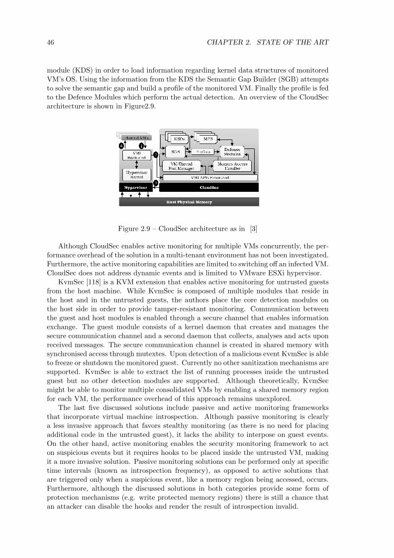
46 CHAPTER 2. STATE OF THE ART
module (KDS) in order to load information regarding kernel data structures of monitoredVM’s OS. Using the information from the KDS the Semantic Gap Builder (SGB) attemptsto solve the semantic gap and build a profile of the monitored VM. Finally the profile is fedto the Defence Modules which perform the actual detection. An overview of the CloudSecarchitecture is shown in Figure2.9.
Figure 2.9 – CloudSec architecture as in [3]
Although CloudSec enables active monitoring for multiple VMs concurrently, the per-formance overhead of the solution in a multi-tenant environment has not been investigated.Furthermore, the active monitoring capabilities are limited to switching off an infected VM.CloudSec does not address dynamic events and is limited to VMware ESXi hypervisor.
KvmSec [118] is a KVM extension that enables active monitoring for untrusted guestsfrom the host machine. While KvmSec is composed of multiple modules that reside inthe host and in the untrusted guests, the authors place the core detection modules onthe host side in order to provide tamper-resistant monitoring. Communication betweenthe guest and host modules is enabled through a secure channel that enables informationexchange. The guest module consists of a kernel daemon that creates and manages thesecure communication channel and a second daemon that collects, analyses and acts uponreceived messages. The secure communication channel is created in shared memory withsynchronised access through mutextes. Upon detection of a malicious event KvmSec is ableto freeze or shutdown the monitored guest. Currently no other sanitization mechanisms aresupported. KvmSec is able to extract the list of running processes inside the untrustedguest but no other detection modules are supported. Although theoretically, KvmSecmight be able to monitor multiple consolidated VMs by enabling a shared memory regionfor each VM, the performance overhead of this approach remains unexplored.
The last five discussed solutions include passive and active monitoring frameworksthat incorporate virtual machine introspection. Although passive monitoring is clearlya less invasive approach that favors stealthy monitoring (as there is no need for placingadditional code in the untrusted guest), it lacks the ability to interpose on guest events.On the other hand, active monitoring enables the security monitoring framework to acton suspicious events but it requires hooks to be placed inside the untrusted VM, makingit a more invasive solution. Passive monitoring solutions can be performed only at specifictime intervals (known as introspection frequency), as opposed to active solutions thatare triggered only when a suspicious event, like a memory region being accessed, occurs.Furthermore, although the discussed solutions in both categories provide some form ofprotection mechanisms (e.g. write protected memory regions) there is still a chance thatan attacker can disable the hooks and render the result of introspection invalid.

2.5. SECURITY MONITORING 47
In the contribution of this thesis presented in Chapter 4, we adapt NIDSs to dynamicchanges that occur in a cloud environment in order to provide adequate monitoring ofthe network traffic that flows towards and from the cloud-hosted information system.Our contribution addresses the adaptation issues that are not taken into account in thepreviously-presented solutions.
2.5.2.2.3 Cloud Firewalls This section presents firewall solutions tailored for cloudenvironments. We focus on industrial solutions since there substantial effort is put ondesigning new cloud firewall solutions or adding new features to existing ones. We focuson two firewall categories: next-generation firewalls and application-level firewalls
Next-Generation Firewalls Nowadays large scale distributed attacks generate mul-tiple security events at different levels of a cloud infrastructure and are considered amongstthe most impactful cyber threats for a cloud environment. One solution in tackling thesetypes of attacks is embedding a next-generation firewall in the cloud infrastructure. Next-generation firewalls are devices that are able to combine multiple functionalities in one:application-oriented access to the Internet, deep analysis of the network traffic (e.g. deeppacket inspection), and finally a user-oriented access policy for on-line applications. Inthis section we discuss next-generation firewall solutions for cloud environments offered bymajor industry players.
A joint solution between VMware and PaloAltoNetworks [119] introduces the VM-Series next-generation firewall which is able to provide application-driven access control(in contrast to traditional firewalls that offer a port and IP address control policy). Theproposed solution is able to dynamically adapt the enforced security policy when topologyevents (e.g. VM migration) occur. Their approach introduces a new feature called tagfor VM identification. Each VM can have multiple tags that represent different featuressuch as IP address, OS, etc. The user is allowed to create security rules based on tagsinstead of static VM objects. VM-Series is fully integrated in the NSX security suite (seeSection 2.5.2.2.3) in order to gain access to the network traffic and topology information ofthe infrastructure. Unfortunately, VM-Series does not take into account specific tenant-security demands (e.g. protection against specific types of threats) and does not offercomponent sharing capabilities between different tenants. The VM-Series solution is alsointegrated in Amazon EC2 [15].
Application-level Firewalls In order to gain insight on which applications aregenerating network traffic, application-level firewalls rose as a solution. Application-levelfirewalls filter network packets based on a set of rules which refer to protocols and statesof the involved applications. When this solution is applied to web applications hosted ina cloud environment it can offer protection against known application-level attacks (suchas SQL injection or cross-site scripting, see Section 2.4.1).
The Amazon Web Application Firewall (WAF) [120] allows tenants to create theirown security rules depending on the type of applications that are hosted in their virtualinfrastructure. Tenants can gain visibility into specific types of requests by setting adedicated filter through the WAF API or create access control lists if they require limitedaccess to their applications. Once created, the rules are installed in a front facing loadbalancer. Although the WAF solutions offer substantial freedom to tenants, by allowingthem to fully customize the deployed ruleset, it does not account for dynamic events(topology- or traffic-related events). Furthermore it is unclear if component sharing isenabled by installing rules of different tenants.

48 CHAPTER 2. STATE OF THE ART
A distributed web application firewall is introduced by Brocade (former SteelApp) [121]that offers automatic rule generation based on application behavior. The in-learning capa-bility of the solution is able to observe on-line applications for a period of time and createaccess control rules. Brocade WAF has three major components that resemble an SDN ar-chitecture model: the Enforcer, the Decider and finally the Administration Interface. TheEnforcer is responsible for enforcing the security rules and inspecting the network traffic.If a packet that does not match the existing rules arrives then the Enforcer sends it tothe Decider which decides whether to allow or block the connection. Then, the Decidergenerates a rule and sends it back to the Enforcer. As the rule generator, the Decider isthe most computing-intensive part of the application and its load depends on the trafficof the application. The Decider is also responsible for auto-scaling in case of increaseddemand. Finally the Administration Interface is responsible for managing the WAF andinserting high-level policy rules that are then translated by the Decider to firewall rules.Although the solution is capable of autoscaling it is unclear what is the CPU penalty oncolocated VMs.
In order to build a tamper-resistant, application-aware firewall that combines in-guestvisibility with the isolation of a VMI monitoring framework, the authors of [122] createdVMwall. Using XenAccess [112] VMwall is able to correlate processes running inside theuntrusted guest with network flows. VMwall maintains a white list of processes that areallowed to make connections and compares the white list to the introspection-generatedlist. If a match is found a rule allowing the connection is inserted in a dedicated filteringmodule in Dom0.
Although VMwall is the pioneering work in creating introspection-based firewalls, itfaces some limitations. First the white list of processes is statically defined and thus doesnot take into account the dynamic nature of a VM where services are continuously addedor removed by tenants. Second, it does not address dynamic topology related events (e.g.VM migration) that occur in a cloud environment. For example, there is no mention of aprioritisation strategy when a migration event occurring in the middle of an introspectionaction. Finally, it is unclear whether the kernel filtering module can be shared betweenmultiple VMs thus enabling sharing of the firewall component.
Xfilter [123] is a self-protection mechanism that filters outgoing packets in the hyper-visor, based on information obtained through introspection. Xfilter was designed as anactive defence mechanism against compromised VMs that are used as stepping stones totarget hosts outside the cloud infrastructure. The framework operates in two phases: De-tection and Inspection. During the detection phase Xfilter only inspects the packet header.Once an attack is detected it automatically passes to the Inspection phase where addi-tional information for the packet is extracted through introspection (process name and IDthat initiated the transfer, port number, destination IP, etc). Then a rule is automaticallygenerated that blocks all packets with that particular set of characteristics. Due to itsdesign, Xfilter is limited in filtering only outgoing connections, thus unable to addressall security cases that are covered by a traditional firewall. As such it is an inadequategeneral-purpose traffic filtering option.
The introspection-based firewall solutions presented are unable to adapt their compo-nents based on the dynamic events that occur in a cloud infrastructure. The contributionof this thesis presented in Chapter 5 addresses dynamic events in virtual infrastructureand adapts its components automatically.
In this thesis we focus on application-level firewalls that adapt their components basedon the list of services that are hosted in the cloud infrastructure.

2.5. SECURITY MONITORING 49
2.5.2.2.4 VESPA: A Policy-Based Self-Protection Framework In this section,we present VESPA [124], a self-protection framework that addresses self-adaptation ofsecurity devices as a reaction to detected attacks.
VESPA was designed in order to tackle the heterogeneous nature of an IaaS cloudenvironment and provide lighter administration of the security devices, combined withlower response time (i.e. when a threat is detected) along with lower error rate (e.g. falsepositives/negatives). The four main design principles of VESPA are:
1. Policy based self-protection: The framework’s design is based on a set of securitypolicies that address the security objectives of the different stakeholders (i.e. tenantsand the provider).
2. Cross-layer self-defence: Based on the fact that a cloud environment is composedof different software layers, the framework’s response to an attack is not limited toa single layer and can involve protection as well as detection functions (as opposedto [1] where the framework’s core functionality is detection).
3. Multiple self-protection loops: The framework offers the ability to select amongdifferent reaction paths in case of an attack. The security administrator can selectbetween loops that offer different trade-offs between reaction time and accuracy.
4. Open architecture: The framework is able to integrate different off-the-self securitycomponents.
The authors created a four-layer framework that implements their four design principles.The first layer, called Resource plane consists of the cloud resources that need to bemonitored (i.e. VMs, tenant networks, etc). The second layer, the Security plane, includesall off-the-shelf security components that can be detection devices (e.g. IDSs) or protectiondevices (e.g. firewalls). The Agent plane is used as a mediator between the heterogeneoussecurity devices and the actual decision making process. The agents that are part of theagent plane act as collectors and aggregators for the different logs produced by the devicesin the security plane. Finally, the last layer, called the Orchestration plane, is responsiblefor making the reaction decision when an attack towards the monitored infrastructureoccurs.
Although VESPA is a security framework that tries to address self-adaptation of the se-curity monitoring devices, the authors consider only security incidents as potential sourcesof adaptation. Other types of dynamic events (see Section 2.2.5) are not considered, conse-quently no reaction mechanisms for these events are implemented. Furthermore, VESPAdoes not include tenant-related security requirements in the definition of the reaction poli-cies. Finally, although VESPA aims at including commodity security monitoring devicesinto the security plane, modifications on their source code are required in order to enablecompatibility with the framework.
The contributions presented in this thesis adapt the security monitoring frameworkbased on environmental changes (topology-, service- and traffic-related) as opposed toVESPA which addresses security incident-oriented adaptation. Furthermore, our contri-butions are able to respect tenant-defined security requirements in the adaptation process.Finally, our contributions do not require modifications on the detection components.
2.5.2.3 Security as A Service Frameworks (SecaaS)
Most cloud providers follow a shared-responsibility security model when it comes to cloudinfrastructures: tenants are responsible for securing anything that they deploy or connect

50 CHAPTER 2. STATE OF THE ART
to the cloud. In order to facilitate the security monitoring of a tenant’s virtual infrastruc-ture cloud providers offer complete monitoring frameworks in the form of products. In thissection we discuss some of these products along with the list of services that they offer.Each provider offers Identity and Access Management solutions for regulating resourceaccess (Amazon: [125], Google: [126], Microsoft: [127]).
• Amazon: Besides the AWS WAF that we discussed in Section 2.5.2.2.3, we focus onsecurity monitoring components such as Shield [128] which is an Intrusion Detectioncomponent tailored towards DDoS attacks. Tenants can create their own rules tomonitor traffic against specific types of DoS attacks like HTTP or DNS floods. Shieldalso provides mitigation techniques like rerouting and can be used in combinationwith WAF for setting proactive filtering against application-level attacks. Otheravailable services include Certificate Manager for deploying SSL certificates. A fulllist of services can be found in [129].
• Google: Google Security scanner [130] is a proactive tool, which automaticallyscans web applications for known vulnerabilities (Flash or SQL injections, outdatedlibraries, etc). Tenants can use the results in order to generate traffic filtering rulesthat proactively block specific types of requests. The Resource Manager [131] reg-ulates access to resources. Interconnected resources are represented hierarchicallyand users can set access rights to a group of resources simply by configuring a parentnode.
• VMware: NSX, the network virtualization platform offers a variety of security toolsincluding traditional edge firewalls that are exclusively managed by the tenant [29]or anti-spoofing mechanisms [132] that allow users to restrict access to a set of IPaddresses that are determined to be spoofed. VMware also provides integrated thirdparty security solutions like TrustPoint [133] which automatically detects networkresources that are not yet configured by performing partial scans of the network.Trustpoint also offers remediation options such as automatically quarantining ma-chines or uninstalling infected applications.
• Microsoft: Advanced threat analytics [134] is a specialised tool for detecting dis-tributed attacks that generate seemingly unrelated events. The tool flags incidentsthat deviate from a previously established normal application behavior. Cloud AppSecurity [135] is another solution for identifying applications that use the network,creating and enforcing customised filtering rules. This product targets SaaS cloudinfrastructures.
This thesis proposes a design for a self-adaptable security monitoring framework withtwo separate instantiations (one for NIDSs and one for firewalls). Our approach borrowselements from Security as a Service frameworks (e.g. integration of tenant security re-quirements and traffic filtering based on the type of hosted applications) but does notoffer a full set of security services like industrial SecaaS solutions.
2.6 Summary
This chapter gave an overview of the state of the art for this thesis. We started witha description of autonomic computing along with its key characteristics. Then the con-cept of cloud computing was introduced. Together these two complementary computingparadigms form the context in which the contributions of this thesis were developed. We

2.6. SUMMARY 51
then focused on describing the IaaS cloud management system that was used in the de-ployment of our prototype, OpenStack. A description of network virtualization techniquesand network management in OpenStack followed. Afterwards, we turned our attentionto security threats in traditional information systems and cloud environments. We thenpresented an overview of the main components of a security monitoring frameworks fo-cusing on two security components: Intrusion Detection Systems and Firewalls. The keyobservations from this chapter are:
• IaaS cloud environments are very dynamic. We have identified three main changecategories: Topology-related, Traffic-related and Service-related changes. Despite thenumerous available cloud security monitoring frameworks there are no solutions thataddress all three types of dynamic events. VESPA, a policy-based self-protectionframework, addresses adaptation of the security monitoring framework but focusingon security events as the main source of adaptation (instead of the three typesmentioned before).
• Although some of the industrial solutions discussed (e.g. Amazon web applicationfirewall) include the option of integrating tenant-specific security requirements in theform of filtering rules, the rule generation is not automatic, forcing the tenants towrite and install the rules themselves.
• Component sharing between tenants is essential in a cloud environment where mul-tiple VMs are deployed in the same physical host. Although the described solutionsrecognize the necessity of a multi-tenant monitoring framework, it still remains adesign requirement that has not been implemented to the best of our knowledge.
Security monitoring for tenant virtualized infrastructures has yet to receive significantattention in the cloud community. Although efforts aimed at including quality of serviceguarantees for different services in a cloud environment have been made [136], securitymonitoring requirements are still not included in cloud SLAs. To our knowledge a self-adaptable security monitoring framework that is able to adapt to the dynamic events ofa cloud environment, allow tenant-driven reconfiguration of the monitoring devices andenable component sharing in order to minimise costs has yet to be implemented. Thegoal of this thesis is to design a framework that is able to address the main limitations ofcurrent solutions discussed in the state of the art. In the following Chapter 3 we presentthe high-level design of our framework. Our framework’s two instantiations incorporatedifferent concepts presented in the state of the art, namely intrusion detection systemsand application-level firewalls. Our first instantiation, presented in 4, is a self-adaptableintrusion detection system tailored for cloud environments. In our second instantiation,presented in Chapter 5, we propose a novel design for securing an application-level firewallusing virtual machine introspection. Our firewall is able to automatically reconfigure theenforced ruleset based on the type of services that run in the deployed VMs. To ourknowledge none of the firewall solutions discussed are able to achieve this.

52 CHAPTER 2. STATE OF THE ART
Chapter 3
A Self-Adaptable SecurityMonitoring Framework for IaaSClouds
3.1 Introduction
In the previous chapter we presented the state of the art in security monitoring for IaaScloud infrastructures. Our analysis has shown that the existing solutions fail to address allthree categories of dynamic events in a cloud infrastructure (topology, monitoring load andservice-related changes) while at the same time integrating monitoring requirements fromdifferent tenants. To address this limitation we have designed a self-adaptable securitymonitoring framework for IaaS cloud environments that is able to:
1. Take into account the various kinds of dynamic events in a cloud infrastructure andadapt its components automatically.
2. Take into account tenant-specific security requirements and reconfigure the securitydevices in such manner that the resulting configuration respects these requirements.
3. Provide accurate security monitoring results without introducing new vulnerabilitiesto the monitored infrastructure.
4. Minimise costs for both tenants and the provider in terms of resource consumption.
In order to illustrate the practical functionality of our framework, we use a simplifiedexample of a cloud-hosted information system. We use the same example in the wholethesis in order to provide consistency for the reader.
This chapter presents the design and implementation of our framework. It is struc-tured as follows: Sections 3.2 and 3.3 present the system and threat model under whichwe designed our framework. Section 3.4 details the objectives of our framework whileSection 3.5 presents our simplified example. Section 3.6 details the high-level design of theadaptation process when a dynamic event occurs. The main components of our frameworkalong with key implementation details are presented in Sections 3.7 and 3.8 respectively.Finally, Section 3.9 summarises our first contribution.
53

54CHAPTER 3. A SELF-ADAPTABLE SECURITY MONITORING FRAMEWORK FOR IAAS CLOUDS
3.2 System Model
We consider an IaaS cloud system with a cloud controller that has a global overview of thesystem. Tenants pay for resources that are part of a multi-tenant environment based ona Service Level Agreement (SLA). Each tenant is in control of an interconnected group ofVMs that hosts various services. No restrictions about the type of deployed applicationsare imposed on tenants. The VMs are placed on available physical servers that are sharedbetween multiple VMs that may belong to different tenants. The cloud provider is respon-sible for the management and reconfiguration of the monitoring framework’s componentsand tenants can express specific monitoring requirements through the SLA or a dedicatedAPI that is part of the monitoring infrastructure. A tenant’s monitoring requirementsinclude: 1. Security monitoring for specific types of threats (e.g. SQL injection attempt,worms, etc), at different levels of the virtual infrastructure (application, system, network)and 2. Performance-related specifications in the form of acceptable values (thresholds) formonitoring metrics. An example of a tenant-specified threshold could be: the maximumaccepted value for the packet drop rate of a network intrusion detection system. Thetenant specifications may lead to the reconfiguration of security monitoring devices thatare shared between tenants or between tenants and the provider.
The cloud controller is responsible for providing networking capabilities to the deployedVMs. Two types of networks are constructed: an internal one between VMs that belongto the same tenant and an external one that is accessible from outside the infrastructure.Each deployed VM is assigned two IP addresses and two domain names: an internal privateaddress and domain name and an external IPv4 address and domain name. Within atenant’s virtual infrastructure, both domain names resolve to the private IP address whileoutside the external domain is mapped to the external IP address.
3.3 Threat Model
We consider software attacks only, that originate from inside or outside the cloud infras-tructure. We assume that like any legitimate tenant, an attacker can run and control manyVMs in the cloud system. Due to multiplexing of the physical infrastructure, these VMscan reside in the same physical machine as potential target VMs. In our model an at-tacker can attempt a direct compromise of a victim’s infrastructure by launching a remoteexploitation of the software running on the deployed VM. This exploitation might targetdifferent levels in the victims infrastructure (system, network, applications). We considerall threats described in Section 2.4.1 to be applicable on a victim’s VMs. Upon successfulexploitation, the attacker can gain full control of the victim’s VM and perform actionsthat require full system privileges such as driver or kernel module installation. Maliciouscode may be executed at both user and kernel levels. The attacker is also in position ofusing the network. We consider all attacker-generated traffic to be unencrypted.
In this work we consider the provider and its infrastructure to be trusted. This meansthat we do not consider attacks that subvert the cloud’s administrative functions via vul-nerabilities in the cloud management system and its components (i.e. hypervisor, virtualswitch, etc). Malicious code cannot be injected in any part in the provider’s infrastructureand we consider the provider’s infrastructure to be physically secure.

3.4. OBJECTIVES 55
3.4 Objectives
The goal of this thesis is to design a self-adaptable security monitoring framework thatdetects attacks towards tenant’s virtualised information systems. We have defined four keyproperties that our framework needs to fulfill: self-adaptation, tenant-driven customiza-tion, security and correctness and finally, cost minimization. In this section we detail eachof them.
3.4.1 Self Adaptation
Our framework should be able to automatically adapt its components based on dynamicevents that occur in a cloud infrastructure. Consequently, the framework should be able toalter the existing configuration of its monitoring components, instantiate new ones, scaleup or down the computational resources available to monitoring components and finally,shut down monitoring components. We distinguish three adaptation categories dependingon their source:
• Service-based adaptation: In this category the framework’s components need tobe adapted due to a change in the list of services that are hosted in the virtualinfrastructure. Addition or removal of existing services could impact the monitoringrequirements, thus require the instantiation of new monitoring devices or reconfigu-ration of existing ones.
• Topology-based adaptation: In this category, the source of adaptation lies inchanges in the virtual infrastructure topology. Sources of these changes includetenant decisions regarding VM lifecycle (i.e. creation, deletion) and provider deci-sions regarding VM placement (i.e. migration). The security monitoring frameworkshould be able to adapt it’s components in order to guarantee an adequate level ofmonitoring despite the new virtual infrastructure topology.
• Monitoring load-based adaptation: In this category, the framework needs toreact to changes in the monitoring load. In the case of network traffic monitoring,an increase in the traffic flowing towards and from applications hosted in the vir-tual infrastructure would trigger an adaptation decision that would guarantee thatenough processing power and network bandwidth (if the monitoring device is ana-lyzing network traffic) is provided to the monitoring components. An adaptationdecision could also involve the instantiation of a new monitoring probe that will beresponsible for a particular traffic segment. In the case of VM activity monitoring,a sudden increase in inside-the-VM activity (i.e. running processes, open files, etc)could lead to altering the computational resources available to the security probemonitoring that particular VM.
3.4.2 Tenant-Driven Customization
Our framework should be able to take into account tenant-specific security requirements.These requirements include application-specific monitoring requests (i.e. requests for de-tecting specific types of attacks depending on the application profile) and monitoring met-rics requests (i.e. detection metrics or performance metrics for the monitoring devices).The framework should be able to consider a given tenant’s requirements in reconfigurationdecisions and enforce these requirements on the affected monitoring devices.
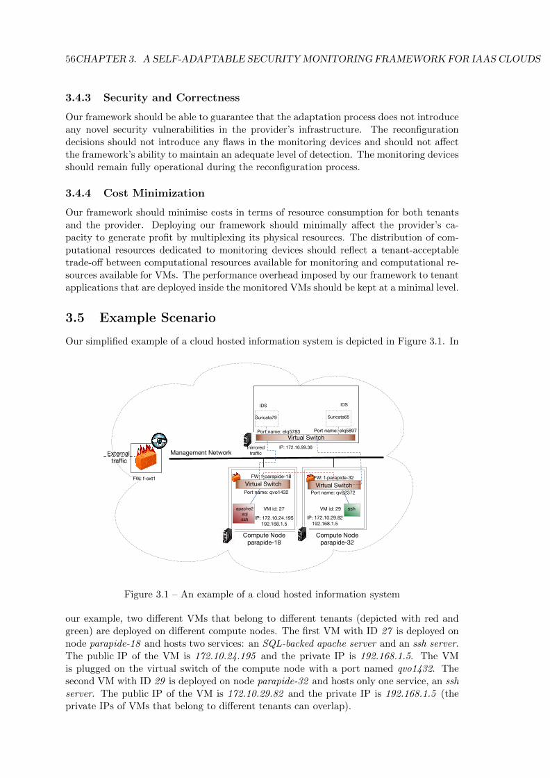
56CHAPTER 3. A SELF-ADAPTABLE SECURITY MONITORING FRAMEWORK FOR IAAS CLOUDS
3.4.3 Security and Correctness
Our framework should be able to guarantee that the adaptation process does not introduceany novel security vulnerabilities in the provider’s infrastructure. The reconfigurationdecisions should not introduce any flaws in the monitoring devices and should not affectthe framework’s ability to maintain an adequate level of detection. The monitoring devicesshould remain fully operational during the reconfiguration process.
3.4.4 Cost Minimization
Our framework should minimise costs in terms of resource consumption for both tenantsand the provider. Deploying our framework should minimally affect the provider’s ca-pacity to generate profit by multiplexing its physical resources. The distribution of com-putational resources dedicated to monitoring devices should reflect a tenant-acceptabletrade-off between computational resources available for monitoring and computational re-sources available for VMs. The performance overhead imposed by our framework to tenantapplications that are deployed inside the monitored VMs should be kept at a minimal level.
3.5 Example Scenario
Our simplified example of a cloud hosted information system is depicted in Figure 3.1. In
Virtual Switch
apache2sqlssh
Compute Nodeparapide-18
Compute Nodeparapide-32
Management Network
Virtual Switch
ssh
mirrored traffic
IDS
Virtual Switch
IDS
External traffic
VM id: 27
IP: 172.10.24.195192.168.1.5
Port name: qvo1432
Suricata65Suricata79
Port name: elq5783 Port name: elq5897
IP: 172.16.99.38
FW: f-ext1 FW: f-parapide-18 FW: f-parapide-32
VM id: 29
IP: 172.10.29.82192.168.1.5
Port name: qvb2372
Figure 3.1 – An example of a cloud hosted information system
our example, two different VMs that belong to different tenants (depicted with red andgreen) are deployed on different compute nodes. The first VM with ID 27 is deployed onnode parapide-18 and hosts two services: an SQL-backed apache server and an ssh server.The public IP of the VM is 172.10.24.195 and the private IP is 192.168.1.5. The VMis plugged on the virtual switch of the compute node with a port named qvo1432. Thesecond VM with ID 29 is deployed on node parapide-32 and hosts only one service, an sshserver. The public IP of the VM is 172.10.29.82 and the private IP is 192.168.1.5 (theprivate IPs of VMs that belong to different tenants can overlap).
3.6. ADAPTATION PROCESS 57
In this simplified example, we include only two types of monitoring devices: network-based IDSs and firewalls. The traffic flowing towards and from the VM on node parapide-18is monitored by a network-based IDS named suricata79 residing on a separate node withIP 172.16.99.38 while the traffic flowing towards and from the VM on node parapide-32is monitored by another network-based IDS named suricata65 residing on the same node.Each compute node has a firewall at the level of the virtual switch (named f-parapide18 forthe compute node parapide18 and f-parapide32 for the compute node parapide32 ). Finally,an edge firewall named f-ext1 is responsible for filtering the traffic that flows towards andfrom the cloud infrastructure to the outside world.
3.6 Adaptation Process
After defining the four main objectives of our monitoring framework, we now describe thethree levels of the adaptation process. The process begins from the adaptation sources, thatcan either be dynamic events or changes in the cloud infrastructure (topology-, service- ormonitoring load-related) or evolving tenant security requirements. It continues with ourframework’s decision making. Finally, the adaptation decision is enforced by reconfiguringthe affected security devices.
First, the adaptation process is triggered by either a change in the cloud infras-tructure (i.e. service, topology or monitoring-load related) or a tenant specific securityrequirement. All necessary information is extracted and forwarded to the adaptationframework. Depending on the type of change different information is propagated to theframework:
• Service-related change: type of service and technical specifications (e.g. port num-bers or range, protocol, authorized connections/users, etc).
• Topology-related change: ID of the affected VM along with network information (e.g.internal/external IP, port on the virtual switch, etc) and the physical node hostingthe VM.
• Monitoring load-related change: device-specific metrics that demonstrate the effectof the monitoring load fluctuation on the monitoring functionality (e.g. packet droprate, memory consumption, etc).
The information extracted from a tenant security requirement includes: specific securityevents (e.g. attack classes or specific threats) and monitoring metrics (e.g. packet droprate). The propagated information is extracted from different sources (i.e. the cloudengine, monitoring devices, SLA, etc).
Once the adaptation framework receives the propagated information, it starts makingthe adaptation decisions. The first step in the decision making process is identifying themonitoring devices affected by the adaptation. The adaptation framework is able to extractthe list of the devices based on the VMs involved in the dynamic events. Depending on themonitoring strategy selected, the group of VMs assigned to a specific monitoring devicecould be determined based on their physical location (e.g. an NIDS monitoring the trafficthat flows towards and from all VMs that are deployed on a particular compute node).The framework has full access to topology and networking information for each monitoringdevice. This information includes: 1. name and IP address of the physical node hosting the

58CHAPTER 3. A SELF-ADAPTABLE SECURITY MONITORING FRAMEWORK FOR IAAS CLOUDS
device (e.g. if a device is running in a container), 2. IP address of the device if applicable,3. list of other co-located devices and finally 4. list of computational resources availableon the node hosting the device (e.g. CPU, memory, etc).
After the adaptation framework has identified the list of affected monitoring devices,it makes the adaptation decision. The adaptation decision can imply the reconfigurationof the monitoring devices so that monitoring for specific types of threats is included orremoved. It can also imply the instantiation of a new monitoring device. The frameworkcan also decide to assign more computational resources to a group of monitoring devicesin order to be able to better manage their computational load. After the decision has beenmade, it is translated to device specific reconfiguration parameters by dedicated frameworkcomponents.
The final stage of the adaptation process is executed at the level of the monitoringdevices. The device-specific reconfiguration parameters are taken into account and themonitoring devices are adapted accordingly. The adaptation framework is able to maintainan adequate monitoring level even during the reconfiguration phase either by using livereconfiguration capabilities of the devices (when applicable) or by incorporating otherstrategies, which enable later inspection of activity (e.g. temporary clone of an HIDS,storing traffic for later inspection in the case of an NIDS). After the adaptation process iscomplete the affected monitoring devices are fully operational.
Although we consider network reconfiguration events such as network migrations partof topology-related changes, our framework does not handle network reconfiguration eventsat this stage.
3.7 Architecture
This section presents the architecture of our self-adaptable security monitoring framework.First a high-level overview of the system is presented followed by the description andfunctionality of each component.
3.7.1 High-Level Overview
The high-level overview of our framework’s architecture is shown in Figure 3.2. The figuredepicts an IaaS cloud with one controller and two compute nodes on which the tenant’svirtualised infrastructure is deployed. Different components of our self-adaptable securitymonitoring framework are included in the figure. A dedicated node is used for hostingdifferent network IDS while an edge firewall filtering the traffic between the outside worldand the cloud is deployed on a standalone host. Firewalls are also included at the level ofthe local switches on the compute nodes. Finally, a log aggregator collects and unifies theevents produced by the different types of security devices.
Our framework is composed of three different levels: tenant, adaptation and monitoringdevices. The monitoring devices level consists of probes (NIDS and firewalls in Figure 3.2)as well as log collectors and aggregators.
The adaptation level consists of all the framework’s components that are responsiblefor designing and enforcing the adaptation process. A dedicated Adaptation Manager,which can be located in the cloud controller, acts as a decision maker. Dedicated com-ponents named Master Adaptation Drivers (MAD), located in the nodes that host themonitoring devices, are responsible for translating the manager’s decision to component-specific configuration parameters are also part of this level. A MAD can be responsible
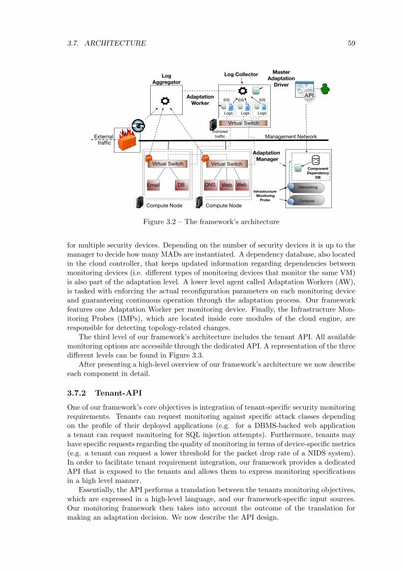
3.7. ARCHITECTURE 59
Virtual Switch
Web Email DNS
Compute Node Compute Node
Management Network
Virtual SwitchComponentDependency
DB
Infrastructure Monitoring
Probe Compute
Networking
Adaptation Manager
DB Web
mirrored traffic
IDS
Virtual Switch
Logs
IDS
Logs
IDS
Logs
External traffic
Log CollectorLog Aggregator
MasterAdaptation
Driver
AdaptationWorker
Figure 3.2 – The framework’s architecture
for multiple security devices. Depending on the number of security devices it is up to themanager to decide how many MADs are instantiated. A dependency database, also locatedin the cloud controller, that keeps updated information regarding dependencies betweenmonitoring devices (i.e. different types of monitoring devices that monitor the same VM)is also part of the adaptation level. A lower level agent called Adaptation Workers (AW),is tasked with enforcing the actual reconfiguration parameters on each monitoring deviceand guaranteeing continuous operation through the adaptation process. Our frameworkfeatures one Adaptation Worker per monitoring device. Finally, the Infrastructure Mon-itoring Probes (IMPs), which are located inside core modules of the cloud engine, areresponsible for detecting topology-related changes.
The third level of our framework’s architecture includes the tenant API. All availablemonitoring options are accessible through the dedicated API. A representation of the threedifferent levels can be found in Figure 3.3.
After presenting a high-level overview of our framework’s architecture we now describeeach component in detail.
3.7.2 Tenant-API
One of our framework’s core objectives is integration of tenant-specific security monitoringrequirements. Tenants can request monitoring against specific attack classes dependingon the profile of their deployed applications (e.g. for a DBMS-backed web applicationa tenant can request monitoring for SQL injection attempts). Furthermore, tenants mayhave specific requests regarding the quality of monitoring in terms of device-specific metrics(e.g. a tenant can request a lower threshold for the packet drop rate of a NIDS system).In order to facilitate tenant requirement integration, our framework provides a dedicatedAPI that is exposed to the tenants and allows them to express monitoring specificationsin a high level manner.
Essentially, the API performs a translation between the tenants monitoring objectives,which are expressed in a high-level language, and our framework-specific input sources.Our monitoring framework then takes into account the outcome of the translation formaking an adaptation decision. We now describe the API design.

60CHAPTER 3. A SELF-ADAPTABLE SECURITY MONITORING FRAMEWORK FOR IAAS CLOUDS
… ……
Adaptation Manager
Master Adaptation Drivers
Adaptation Workers
Security DevicesLevel
AdaptationLevel
TenantLevel
Figure 3.3 – The framework’s different levels
3.7.2.1 API Design
The design of our API is organised in three distinct parts. We detail each one. In orderto simplify authentication we have made the design choice to integrate our API into theprovider’s API and make it available through the web.
3.7.2.1.1 Tenant-exposed part: The first part of our API is directly exposed tothe tenants. Each tenant uses its unique identifier in order to access the tenant-exposedpart through the web. After successful authentication, the tenant has access to the listof monitoring services that are activated in its virtual infrastructure along with detailedrecord about each service. The information available about each monitoring service are:attack/threat classes (e.g. SQL injection, cross site scripting, etc), list of VMs that areunder this monitoring service and finally, a time field that specifies when this option wasactivated.
A tenant can add a new monitoring service or remove an existing one through a ded-icated add/delete option in the API. In the event of a new monitoring service addition,the tenant is given the option to select a monitoring service only amongst the ones thatare available/supported by the self-adaptable monitoring framework.
After selecting the monitoring service the tenant adds the IDs of the VMs that it wantsthis service to be applied on. A second option available for tenants is tuning of SLA-definedmonitoring metrics. Each tenant has access to a list of SLA-defined monitoring metricsand can increase or decrease their value.
Finally, a list of the applications that are deployed on its provisioned VMs is providedby each tenant. The information available for each application is:
• its name.
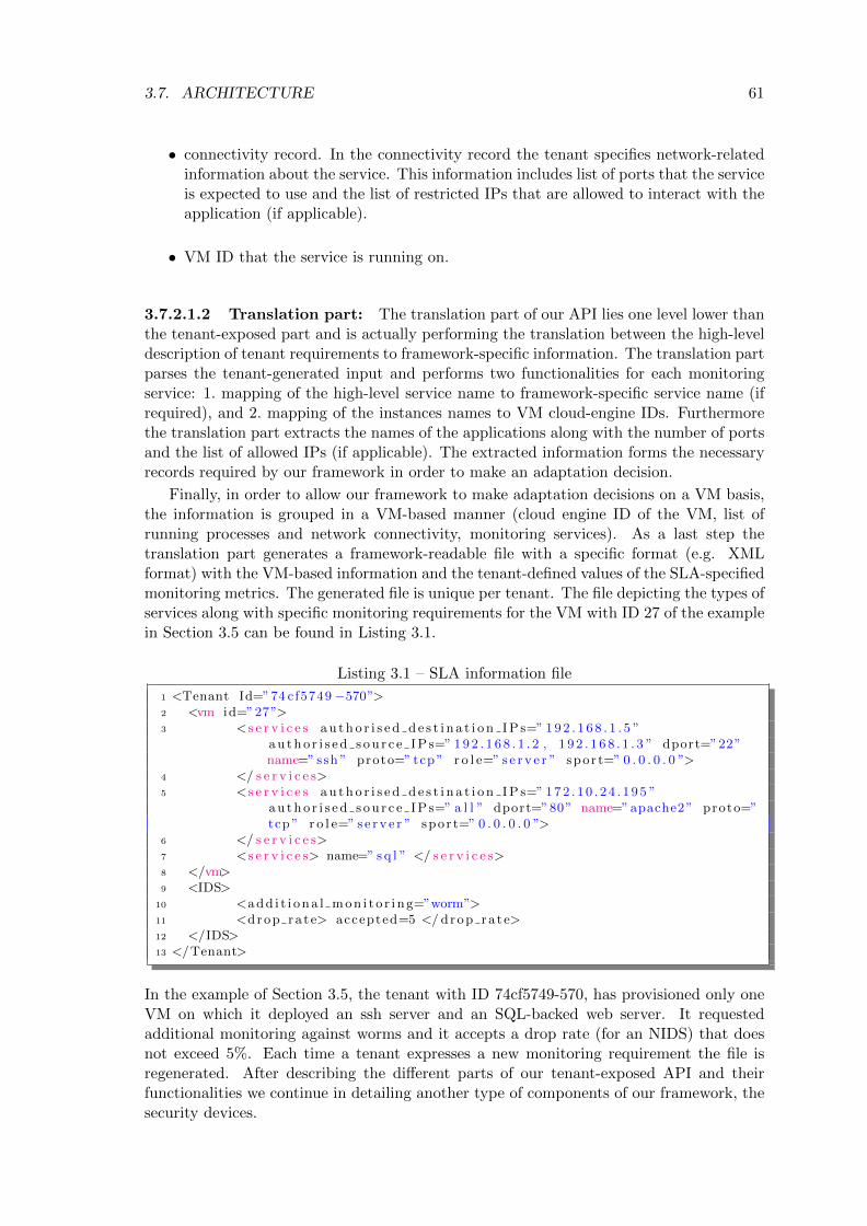
3.7. ARCHITECTURE 61
• connectivity record. In the connectivity record the tenant specifies network-relatedinformation about the service. This information includes list of ports that the serviceis expected to use and the list of restricted IPs that are allowed to interact with theapplication (if applicable).
• VM ID that the service is running on.
3.7.2.1.2 Translation part: The translation part of our API lies one level lower thanthe tenant-exposed part and is actually performing the translation between the high-leveldescription of tenant requirements to framework-specific information. The translation partparses the tenant-generated input and performs two functionalities for each monitoringservice: 1. mapping of the high-level service name to framework-specific service name (ifrequired), and 2. mapping of the instances names to VM cloud-engine IDs. Furthermorethe translation part extracts the names of the applications along with the number of portsand the list of allowed IPs (if applicable). The extracted information forms the necessaryrecords required by our framework in order to make an adaptation decision.
Finally, in order to allow our framework to make adaptation decisions on a VM basis,the information is grouped in a VM-based manner (cloud engine ID of the VM, list ofrunning processes and network connectivity, monitoring services). As a last step thetranslation part generates a framework-readable file with a specific format (e.g. XMLformat) with the VM-based information and the tenant-defined values of the SLA-specifiedmonitoring metrics. The generated file is unique per tenant. The file depicting the types ofservices along with specific monitoring requirements for the VM with ID 27 of the examplein Section 3.5 can be found in Listing 3.1.
Listing 3.1 – SLA information file
1 <Tenant Id=”74 cf5749 −570”>2 <vm id=”27”>3 <s e r v i c e s au tho r i s e d d e s t i n a t i o n IP s=” 192 . 1 6 8 . 1 . 5 ”
au tho r i s ed s ou r c e IP s=” 192 . 1 6 8 . 1 . 2 , 1 9 2 . 1 6 8 . 1 . 3 ” dport=”22”name=” ssh ” proto=” tcp ” r o l e=” s e r v e r ” spor t=” 0 . 0 . 0 . 0 ”>
4 </ s e r v i c e s>5 <s e r v i c e s au tho r i s e d d e s t i n a t i o n IP s=” 172 . 10 . 2 4 . 195 ”
au tho r i s ed s ou r c e IP s=” a l l ” dport=”80” name=”apache2” proto=”tcp ” r o l e=” s e r v e r ” spor t=” 0 . 0 . 0 . 0 ”>
6 </ s e r v i c e s>7 <s e r v i c e s> name=” sq l ” </ s e r v i c e s>8 </vm>9 <IDS>
10 <add i t i ona l mon i t o r i ng=”worm”>11 <drop ra te> accepted=5 </ drop ra te>12 </IDS>13 </Tenant>
In the example of Section 3.5, the tenant with ID 74cf5749-570, has provisioned only oneVM on which it deployed an ssh server and an SQL-backed web server. It requestedadditional monitoring against worms and it accepts a drop rate (for an NIDS) that doesnot exceed 5%. Each time a tenant expresses a new monitoring requirement the file isregenerated. After describing the different parts of our tenant-exposed API and theirfunctionalities we continue in detailing another type of components of our framework, thesecurity devices.

62CHAPTER 3. A SELF-ADAPTABLE SECURITY MONITORING FRAMEWORK FOR IAAS CLOUDS
3.7.3 Security Devices
Security devices include all devices and processes that perform the actual monitoringfunctionality. The type of devices included are: intrusion detection systems (network orhost based), firewalls, vulnerability scanners, antiviruses, etc. The monitoring devices canbe installed at any point in the cloud infrastructure and can monitor part of the tenantsor the provider infrastructure.
Although the monitoring devices perform different types of monitoring under differentconfigurations, the common denominator between all types of devices is the production ofdetailed log files. In order to efficiently manage and unify logs originating from the securitydevices we include log collectors and aggregators in this category (although they do notperform actual monitoring tasks). Log collectors can be co-located with one or multiplemonitoring instances and can perform local or remote collection of logs. Aggregators areresponsible for looking for specific patterns, defined by the framework’s administrator,inside the log files and summarizing events.
3.7.4 Adaptation Manager
The Adaptation Manager (AM) is one of our framework’s core components. It is responsi-ble for making the adaptation decisions that affect the monitoring devices of the monitoringframework. The AM is able to handle dynamic events inside the cloud infrastructure andguarantees that an adequate level of monitoring is maintained. The Adaptation Managerhas a complete overview of the state of the monitoring framework which is comprised bythe following information:
• topological overview: list of monitoring devices and their location (nodes on whichthey are deployed and IP addresses of the nodes),
• functional overview: a mapping between VMs and monitoring devices. One de-vice can be mapped to multiple VMs and vice versa. The functional overview ofthe system provides the necessary information regarding which monitoring device ismonitoring which subset of the deployed VMs. Depending on the monitoring strat-egy selected, a monitoring device can be responsible for all the VMs that are hostedin a particular location (e.g. an NIDS monitoring the traffic that flows towards andfrom all the VMs deployed on a specific compute node).
Upon the occurrence of a dynamic event (e.g. VM migration) the AM performs theactions presented in Algorithm 1 in order to make an adaptation decision:
Algorithm 1 The adaptation decision algorithm
1: function adaptation(dynamic event)2: list of services← map(dynamic event.VM id, vm information file )3: affected devices, agents← map(dynamic event.VM id)4: for i in affected devices do5: reconfiguration required← decide(i, list of services)
6: propagate decision(agents, reconfiguration required)
• Map the ID of the VM affected by the change to the list of services running insidethe VM (line 2 in Algorithm 1). This is done by parsing the information providedby the API-generated file (sla info.xml in Listing 3.1).

3.7. ARCHITECTURE 63
• Identify the monitoring devices responsible for the affected VM (line 3 in Algo-rithm 1). These are the monitoring devices that will be adapted. This is done byusing information that is provided by the Component Dependency Database (seeSection 3.7.6). The information regarding the list of running services and the list ofmonitoring devices that are going to be adapted are combined in a single file calledvm information file. The resulting file for the example information system describedin Section 3.5, can be found in Listing 3.2. In the example of Section 3.5, three ser-vices are deployed on that particular VM with ID 27 (ssh server, apache web serverand an SQL database) while the VM is monitored by a signature-based IDS namedsuricata65.
Listing 3.2 – VM information file
1 <vm id=”27”>2 <s e r v i c e s au tho r i s e d d e s t i n a t i o n IP s=” 192 . 1 6 8 . 1 . 4 ”
au tho r i s ed s ou r c e IP s=” 192 . 1 6 8 . 1 . 2 , 1 9 2 . 1 6 8 . 1 . 3 ” dport=”22” name=” ssh ” proto=” tcp ” r o l e=” s e r v e r ” spor t=” a l l ”>
3 </ s e r v i c e s>4 <s e r v i c e s au tho r i s e d d e s t i n a t i o n IP s=” 172 . 10 . 124 . 195 ”
au tho r i s ed s ou r c e IP s=” a l l ” dport=”80” name=”apache2”proto=” tcp ” r o l e=” s e r v e r ” spor t=” a l l ”>
5 </ s e r v i c e s>6 <s e r v i c e s name=” sq l ”>7 <currentIDS ho s t i p=” 172 . 1 6 . 9 9 . 3 8 ” name=” su r i c a t a79 ” type=”
s i gna tu r e ba s ed ” add i t i ona l mon i t o r i ng=”worm” drop ra te=”5” > </newIDS>
8 </vm>
• Decide on the type of reconfiguration required (line 5 in Algorithm 1). Dependingon the type of monitoring devices and the event category different reconfigurationtypes might be necessary (e.g. rule addition or removal, module activation, whitelist creation, new probe instantiation, computational resource redistribution, etc).
• Propagate the reconfiguration parameters to the agents responsible for enforcing theadaptation decision (line 6 in Algorithm 1).
In case of a topology-related dynamic event all steps are performed while in the caseof a service- or monitoring load-related change or a tenant-specific changed monitoringrequirement only steps 3 to 6 are performed.
The AM is also responsible for handling performance degradation of the monitoringprobes. The AM sets predefined thresholds for a set of device specific performance metricsand then allows each monitoring device to raise an alert in case one of the predefinedthresholds is violated. The AM then decides if a new probe is necessary. If a new probeis instantiated the AM propagates the necessary information regarding monitoring loadredistribution to the lower level agents.
In a cloud environment often dynamic events occur simultaneously. In order to handlethe adaptations of the security devices that originate from these events, the AM canhandle multiple adaptation events simultaneously. In the event of two different adaptationdecisions affecting the same existing monitoring device, we distinguish three outcomesdepending on the arguments of the adaptation decisions:
• The adaptation decisions contain different adaptation arguments: In this case thereis no conflict between the decisions and the reconfigurations can proceed.

64CHAPTER 3. A SELF-ADAPTABLE SECURITY MONITORING FRAMEWORK FOR IAAS CLOUDS
• The adaptation decisions contain the same arguments or there is a partial matchbetween the two argument sets: In this case depending on the nature of the adapta-tion decisions (activation or deactivation of monitoring parameters) we can foreseetwo outcomes:
1. Both decisions lead to activation or deactivation of monitoring parameters: Inthis case there is no conflict and the reconfigurations can proceed.
2. One decision leads to activation of monitoring parameters while the other todeactivation: In this case there is a conflict between the reconfigurations. Inorder to guarantee an adequate level of detection, our framework adopts thestrategy of keeping the matching arguments activated.
3.7.5 Infrastructure Monitoring Probes
The Infrastructure Monitoring Probes (IMPs) are located inside different core modules(networking, compute) of the cloud engine and are responsible for detecting topology re-lated changes. The detected changes include VM lifecycle (e.g. start, stop) and placement(i.e. migration) changes. Once a topology-related change occurs an IMP intercepts the dy-namic event and extracts all the necessary VM-related information from the cloud engine.The information includes: networking records (external and internal IP address, networkport on the virtual switch) and compute records (VM ID, source and destination node– in case of a migration–, tenant ID) of the affected instance. Then the IMP forwardsthis information to the Adaptation Manager in order to make the adaptation decision. Al-though located inside the cloud engine IMPs do not preempt normal cloud operations (e.g.VM-lifecycle decisions or network-related reconfigurations) during the reconfiguration ofmonitoring devices.
3.7.6 Component Dependency Database
In complex security monitoring frameworks that consist of different components, inter-dependencies between security devices can lead to troublesome security issues. Recon-figuration of a single monitoring component can create the need for reconfiguring a setof secondary monitoring devices. In the case of our framework, an adaptation decisionthat was triggered by a dynamic event (e.g. a service stop inside a monitored guest)can affect separate security devices: an active monitoring device (e.g. a firewall) and apassive monitoring device (e.g. an IDS). In both devices reconfiguration is necessary inorder to reflect a change in the monitoring process that was caused by the dynamic event(e.g. delete rules that filter traffic for the stopped service for the firewall and de-activatethe rules that monitor traffic for the stopped service in the IDS). In order to facilitateidentification of all affected devices when making an adaptation decision, we introduce theDependency Database. The Dependency Database is located inside the cloud controllerand is responsible for storing security device information for each monitored VM.
Our dependency database consists of two separate tables a VM info table and a De-vice info table that provide respectively the functional and topological views to the Adap-tation Manager. The columns in theVM info consist of the names of all security devicesinvolved in the monitoring of a particular VM (identified with its ID, placing one VMper line). Using the VM ID as a primary key, the Adaptation Manager can extract thelist of monitoring devices that are responsible for this VM. These are the devices thatare affected by an adaptation decision caused by a dynamic event involving that VM. TheVM info table for the VMs of the example of Section 3.5 can be found in Table 3.1. In this

3.8. IMPLEMENTATION 65
Table 3.1 – The VM info table
VM ID Network IDS Host IDS External-firewall Switch-firewall
27 suricata79 ossec1 f-ext1 f-parapide-1829 suricata65 ossec4 f-ext1 f-parapide-32
example we see that for the VM with ID 27 there is a network IDS named suricata79, ahost IDS named ossec1 and two different firewalls, one edge, named f-ext1, and one insidethe local switch, named f-parapide-18. A single VM can be monitored by different typesof IDS (host- and network-based).
The Device info table is used to store device specific information. The AdaptationManager uses each device name in order to extract the following information: location ofthe device (IP address of the physical node hosting the device) and type of the device TheDevice info table for suricata65 IDS can be found in Table 3.2. In this example we see
Table 3.2 – The Device info table
Device Name Location Type of device
suricata65 172.16.99.38 signature based
that the suricata65 network IDS is located on a node with IP address 172.16.99.38 andis a signature-based NIDS. When a dynamic event occurs, the AM uses the informationavailable in the Dependency Database to identify the full list of affected devices. Eachtime a new monitoring device is instantiated a corresponding entry with all the necessaryinformation is added by the AM in the two tables.
3.8 Implementation
We have developed a prototype for our framework from scratch in Python. We used Open-Stack (version Mitaka) [32] as the cloud management system. In order to enable networktraffic mirroring we used Open vSwitch (OvS) [137] as a multilayer virtual switch. OvSis only compatible with later versions of OpenStack that use Neutron for providing net-working services for deployed VMs. Consequently, version Mitaka was selected. We usedLibvirt [138] for interacting with the underlying hypervisor. This section presents a fewimportant implementation aspects. Namely, we focus on the details of two of our frame-work’s main components: the Adaptation Manager and the Infrastructure MonitoringProbe.
3.8.1 Adaptation Manager
In order for the manager to be able to handle multiple adaptation events in parallel, amulti-threaded model approach was adopted. A master thread is responsible for receiv-ing notifications regarding topology-related changes from the Infrastructure MonitoringProbes. The notification mechanism currently supports two versions: creating and listen-ing to a dedicated socket, or placing a notification adapter (using the inotify [139] Linuxutility) in a specific directory for tracking events (modify, close write) on the directory’sfiles. Once the AM receives an event, the AM performs the steps described in Algorithm 2:
1. A worker thread is spawned for handling the considered adaptation event. In or-der to retrieve the information about the VM involved in the topology change,
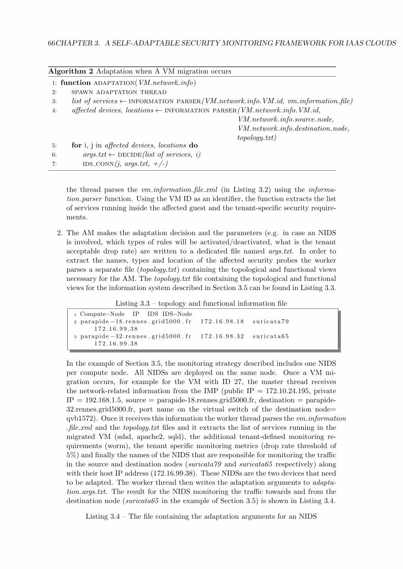
66CHAPTER 3. A SELF-ADAPTABLE SECURITY MONITORING FRAMEWORK FOR IAAS CLOUDS
Algorithm 2 Adaptation when A VM migration occurs
1: function adaptation(VM network info)2: spawn adaptation thread3: list of services← information parser(VM network info.VM id, vm information file)4: affected devices, locations← information parser(VM network info.VM id,
VM network info.source node,VM network info.destination node,topology.txt)
5: for i, j in affected devices, locations do6: args.txt← decide(list of services, i)7: ids conn(j, args.txt, +/-)
the thread parses the vm information file.xml (in Listing 3.2) using the informa-tion parser function. Using the VM ID as an identifier, the function extracts the listof services running inside the affected guest and the tenant-specific security require-ments.
2. The AM makes the adaptation decision and the parameters (e.g. in case an NIDSis involved, which types of rules will be activated/deactivated, what is the tenantacceptable drop rate) are written to a dedicated file named args.txt. In order toextract the names, types and location of the affected security probes the workerparses a separate file (topology.txt) containing the topological and functional viewsnecessary for the AM. The topology.txt file containing the topological and functionalviews for the information system described in Section 3.5 can be found in Listing 3.3.
Listing 3.3 – topology and functional information file
1 Compute−Node IP IDS IDS−Node2 parapide −18. rennes . gr id5000 . f r 1 72 . 1 6 . 9 8 . 1 8 su r i c a t a79
172 . 1 6 . 9 9 . 3 83 parapide −32. rennes . gr id5000 . f r 1 72 . 1 6 . 9 8 . 3 2 su r i c a t a65
172 . 1 6 . 9 9 . 3 8
In the example of Section 3.5, the monitoring strategy described includes one NIDSper compute node. All NIDSs are deployed on the same node. Once a VM mi-gration occurs, for example for the VM with ID 27, the master thread receivesthe network-related information from the IMP (public IP = 172.10.24.195, privateIP = 192.168.1.5, source = parapide-18.rennes.grid5000.fr, destination = parapide-32.rennes.grid5000.fr, port name on the virtual switch of the destination node=qvb1572). Once it receives this information the worker thread parses the vm informationfile.xml and the topology.txt files and it extracts the list of services running in the
migrated VM (sshd, apache2, sqld), the additional tenant-defined monitoring re-quirements (worm), the tenant specific monitoring metrics (drop rate threshold of5%) and finally the names of the NIDS that are responsible for monitoring the trafficin the source and destination nodes (suricata79 and suricata65 respectively) alongwith their host IP address (172.16.99.38). These NIDSs are the two devices that needto be adapted. The worker thread then writes the adaptation arguments to adapta-tion args.txt. The result for the NIDS monitoring the traffic towards and from thedestination node (suricata65 in the example of Section 3.5) is shown in Listing 3.4.
Listing 3.4 – The file containing the adaptation arguments for an NIDS

3.9. SUMMARY 67
1 s i gna tu r e ba s ed2 su r i c a t a653 apache24 s q l5 ssh 1 92 . 1 6 8 . 1 . 2 , 1 9 2 . 1 6 8 . 1 . 36 worm7 5
3. The worker thread sends the dedicated file through a secure connection (using adedicated function called ids conn) to a MAD located in the node(s) hosting theaffected security devices. The ids conn function uses the IP address of the nodehosting the device, and the name of the security device in order to establish theconnection
4. A dedicated operator (e.g. + or -), that is decided by the AM is sent togetherwith the file containing the adaptation arguments, indicates whether the adaptationrequires an activation or deactivation of monitoring parameters. In our example,the operator sent with the file in Listing 3.4 is a + indicating that the monitoringparameters need to be activated. In case of an adaptation decision that affectsmultiple security components in different locations, a separate thread per componentis created in order to facilitate the parallel transmission of the adaptation file.
3.8.2 Infrastructure Monitoring Probe
3.9 Summary
In this chapter we have described the design of a self-adaptable security monitoring frame-work. Our framework was designed in order to address the four main objectives: self-adaptation, tenant-driven customization, security and cost minimization. In this chapterwe described how the core component of our framework, the Adaptation Manager, or-chestrates the adaptation decisions in order to meet the self-adaptation and tenant-drivencustomization objectives.
A detailed description of the adaptation process, from the dynamic event that triggersthe adaptation to the actual reconfiguration of the security probes was presented. Duringthe process, we have demonstrated that the Adaptation Manager respects tenant-definedmonitoring metrics by including them in the adaptation parameters. The AM is able tomake the adaptation decisions independently from the type of security device. Conse-quently, our framework is able to integrate different types of security monitoring devices.The Master Adaptation Drivers (described in more detail in the following chapter) areresponsible for translating the adaptation decision to device-specific parameters. The re-maining two objectives (security and cost minimization) are discussed in the followingchapters. Furthermore, we described remaining individual components of our frameworkand their functionality: the Adaptation Manager, which is the core of our framework,making all the adaptation decisions, the tenant-API, which allows tenants to express theirmonitoring requirements and translates them to AM-readable information, the Infrastruc-ture Monitoring Probes, which are responsible for detecting dynamic-related events andnotifying the AM and the Dependency Database which holds all necessary informationregarding interdependent security devices. Each component’s functionality contributes toan accurate adaptation decision.

68CHAPTER 3. A SELF-ADAPTABLE SECURITY MONITORING FRAMEWORK FOR IAAS CLOUDS
Selected implementation details of two of our framework’s components (the AdaptationManager and the Infrastructure Monitoring Probes) were presented. In order to facilitatemultiple adaptation decisions in parallel, the AM was implemented using a multi-threadedapproach. Instead of using traditional network-based communication between differentcomponents, we opted for a faster file-based approach using the Inotify Linux utility. Inorder to obtain accurate and up-to-date VM-related information we made the design choiceof placing the IMPs inside core modules of the cloud engine.
Two separate instantiations of our framework are discussed in the following chap-ters. The proposed instantiations focus on the adaptation of two different types of secu-rity devices. The first instantiation presents a self-adaptable network intrusion detectionsystem called SAIDS, while the second instantiation presents a secure application-levelintrospection-based firewall called AL-SAFE.
Chapter 4
SAIDS: A Self-AdaptableIntrusion Detection System forIaaS Cloud Environments
In this chapter we present SAIDS the first instantiation of our security monitoring frame-work. SAIDS is a self-adaptable network intrusion detection system designed for IaaScloud environments. A preliminary version of this contribution was published in [140]. Webegin with a description of SAIDS objectives in Section 4.1, followed by the presentation ofindividual SAIDS components in Section 4.2. Security threats are discussed in Section 4.3.The adaptation process along with events that trigger the adaptation are featured in Sec-tion 4.4. Implementation details and our detailed evaluation plan along with obtainedresults are described in Sections 4.5 and 4.6 respectively. Finally, Section 4.7 summarisesthis chapter and presents key observations.
4.1 Objectives
In this section we discuss in detail the objectives that SAIDS should meet.
• Self-Adaptation: SAIDS should react to dynamic events that occur in a cloudenvironment and adapt the network intrusion detection devices accordingly. Theseevents refer to topology-related changes in the virtual or hardware infrastructure andservice-related changes. Virtual infrastructure changes are caused by tenant decisionsregarding VM-lifecycle (i.e. creation, deletion) or provider decisions regarding VMplacement (i.e. migration). Changes in the hardware infrastructure refer to additionor removal of servers. Service related changes refer to the addition or removal ofservices in the deployed VMs.
• Customization: based on the type of services that are hosted on the deployed VMsSAIDS should allow tenants to customise the events that are being detected. Tenantscan request monitoring against specific types of threats that refer to different levelsof their infrastructure (i.e. application, system or network level). Common threats(e.g. worms, SQL injection attempts) can be detected using generic rules out ofpublic or commercial rule repositories [141]. SAIDS should provide tenants with theability to use custom rules (i.e. tailored for their deployed systems) for commonthreats in order to improve detection quality. Furthermore, tenants should be able
69

70CHAPTER 4. SAIDS: A SELF-ADAPTABLE INTRUSION DETECTION SYSTEM FOR IAAS CLOUD ENVIRONMENTS
to write and include their own customised IDS rules against more specific types ofthreats that target their deployed services.
• Scalability: the number of deployed SAIDS IDSs should adjust to varying con-ditions: load of the network traffic monitored, number of physical servers in thedatacenter, number of VMs in the virtual infrastructure. SAIDS should be able toalter the resources available to its IDSs in the event of a degradation in the qualityof detection. Different metrics are used in order to estimate the quality of detec-tion for which SAIDS takes into account tenant-defined thresholds. SAIDS uses thefollowing metrics: packet drop rate (the value of this metric can be improved by al-tering the computational resources available to the SAIDS IDSs), detection rate (thevalue of this metric is related to SAIDS IDSs packet drop since it also demonstratesthe ability of an IDS to process the input stream without dropping packets, thuscan indirectly be improved by altering the computational resources available to theSAIDS IDSs) and false positive rate.
• Security and Correctness: SAIDS should guarantee that an adequate level ofdetection is maintained during the adaptation of the SAIDS IDSs. The adaptationof the SAIDS IDSs should not allow attacks that otherwise would have been de-tected to remain undetected. Furthermore SAIDS should not create new securityvulnerabilities in the provider’s infrastructure.
4.2 Models and Architecture
In this section we present the system and threat model used in SAIDS along with a detaileddescription of SAIDS architecture and individual components.
We adopt the same system and threat model as the ones described in Chapter 3,Sections 3.2 and 3.3.
4.2.1 Architecture
This section describes SAIDS architecture. We first present a high level overview of SAIDSand then we focus on describing the functionality of each individual component.
SAIDS consists of four major components as depicted in Figure 4.1: the Local IntrusionDetection Sensors (LIDS), the Adaptation Worker (AW), the Master Adaptation Driver(MAD) and the Mirror Worker (MW). The LIDSs are deployed on dedicated nodes andour framework features one AW per LIDS (the AW is installed inside the LIDS). SAIDSfeatures one MAD per dedicated node. Finally, we include one Mirror Worker per computenode.
4.2.1.1 Component Description
This section focuses on the description of each individual component’s functionality. Thecomponents are run by the cloud provider.
4.2.1.1.1 Local Intrusion Detection Sensors: LIDS are used for collecting andanalyzing network packets that are flowing through subsets of virtual switches. The de-tection technique that is used can either be signature- or anomaly-based. A signature-based technique has high true positive rate in detecting known attacks as opposed to an

4.2. MODELS AND ARCHITECTURE 71
Local Switch
mirrored traffic
Web EmailDNS
Compute Node Compute Node
Management Network
Local SwitchVM info
SLA info
Infrastructure Monitoring
Probe Compute
Networking
Adaptation Manager
Master AdaptationDriver
LIDS1
Local Switch
DB Web
AdaptationWorker
Ruleset
mirrored traffic
LIDS2
Local Switch
AdaptationWorker
Ruleset
MirrorWorker
Figure 4.1 – SAIDS architecture
anomaly-based technique which is more effective in detecting unknown attacks. Further-more, a signature-based LIDS requires zero training time making it a suitable choice forimmediate efficiency in contrast with an anomaly-based LIDS which requires a trainingperiod. SAIDS supports both types of detection techniques allowing tenants to select theirpreferred trade-off. In a signature-based LIDS the packets are decoded and preprocessedin order to check their payload for suspicious patterns by comparing it with a preloadedset of rules. If a match is found the packet is logged and an alert is generated. The rulescan match either service, network or system level threats. LIDSs organize rules in distinctsets named rule categories. Rules against variants of the same threat are organized in thesame rule category. Once the category is included in the configuration file of a signature-based LIDS all the subsequent rules of that category are activated. All the logs from LIDSinstances that are located on a given node are collected by a local log collector instancerunning on the same node.
4.2.1.1.2 Adaptation Worker: The AW is located inside the LIDS and has severalroles: First, it is responsible for reconfiguring the enforced ruleset by reloading the newconfiguration file that was created by the MAD. Second, the AW can detect if the de-tection process has failed and restart it if necessary. Third, the AW periodically reportsLIDS-specific monitoring metrics (e.g. packet drop rate) back to the MAD and ensuresthat during the reconfiguration process the LIDS continues to operate seamlessly, so anadequate level of detection is maintained. Finally, once the reconfiguration process hasbeen completed successfully, the AW reports back to the MAD.
4.2.1.1.3 Master Adaptation Driver: A MAD is responsible for the reconfigura-tion and lifecycle of a group of LIDSs on a given node. In order to satisfy the scalabilityobjective of SAIDS the MAD was designed for handling multiple reconfiguration requestsin parallel. When a dynamic event occurs, the adaptation parameters are sent by the AMto the MAD. The MAD translates them to LIDS-specific rules and creates a new config-uration file that contains the rules that need to be activated in the affected LIDS. In theevent of a new LIDS is instantiated the MAD is responsible for creating an endpoint for
72CHAPTER 4. SAIDS: A SELF-ADAPTABLE INTRUSION DETECTION SYSTEM FOR IAAS CLOUD ENVIRONMENTS
that LIDS on the local switch and reconfiguring the traffic distribution between LIDSs onthe local switch.
The MAD periodically communicates with different AW instances in order to gain ac-cess to LIDS-specific performance metrics. In case of a performance degradation the MADis responsible for deciding between instantiating a new probe or assigning more compu-tational resources to an existing one. Finally, the MAD can periodically obtain resourceutilization information about each LIDS. The time between two consecutive resource uti-lization queries can be defined by the tenant.
4.2.1.1.4 Mirror Worker: The MW has two different roles: First, it is responsiblefor checking whether the traffic that flows to and from a group of VMs that are hosted in aparticular compute node is correctly mirrored to the corresponding LIDS node(s). Secondif a mirroring endpoint does not exist the mirror worker creates it on the underlying localswitch.
4.2.1.1.5 Safety Mechanism: SAIDS features a safety mechanism inside each com-pute node that guarantees that the VM participating in a dynamic event (e.g. a migratedVM) does not enter an active state before the corresponding LIDS has been successfullyreconfigured. The AM notifies the safety mechanism that the LIDS reconfiguration hasbeen completed successfully. Although SAIDS has this mechanism enabled by default,in our design we allow tenants to choose whether to disable it or not. The choice be-tween enabling the safety mechanism or not demonstrates a trade-off between securityand performance. Consequently, enabling the mechanism could impact the performanceof network-critical applications that run inside the affected VM.
After presenting SAIDS individual components we now discuss potential security threatsagainst SAIDS.
4.3 Security Threats
In this section we describe the potential vulnerabilities in SAIDS design and potentialvulnerabilities added by SAIDS in the provider’s infrastructure. We present our designchoices for addressing each one.
4.3.1 SAIDS Configuration Files
The first type of input that is required for the adaptation of the LIDSs is a set of con-figuration files that are used for translating the adaptation arguments (which include anytenant-defined monitoring requests) to rule category names. The first file contains theadaptation arguments while the second file provides a mapping between specific types oftenant-deployed services and rule category names. An attacker could alter the contentsof the files and create false adaptation arguments that would result in the activation ofincorrect rule categories or deactivation of correct ones. These files are simple text orXML files for which SAIDS features robust parsers. The input file is pre-processed using aSAIDS-specific filter that verifies that only SAIDS-specific elements and printable ASCIIstrings without special characters are present in the files. Furthermore the value of eachentry (i.e. monitoring request) partially matches the rule name (exact definition in Sec-tion 4.4.2), so any complex interpretation is avoided. Following up on the list of deployedservices in the example of Section 3.5, the file containing the adaptation arguments afterthe adaptation decision can be found in Listing 4.1:
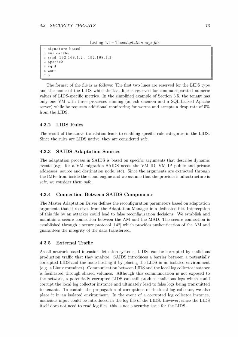
4.3. SECURITY THREATS 73
Listing 4.1 – Theadaptation args file
1 s i gna tu r e ba s ed2 su r i c a t a653 sshd 192 . 1 6 8 . 1 . 2 , 1 9 2 . 1 6 8 . 1 . 34 apache25 sq ld6 worm7 5
The format of the file is as follows: The first two lines are reserved for the LIDS typeand the name of the LIDS while the last line is reserved for comma-separated numericvalues of LIDS-specific metrics. In the simplified example of Section 3.5, the tenant hasonly one VM with three processes running (an ssh daemon and a SQL-backed Apacheserver) while he requests additional monitoring for worms and accepts a drop rate of 5%from the LIDS.
4.3.2 LIDS Rules
The result of the above translation leads to enabling specific rule categories in the LIDS.Since the rules are LIDS native, they are considered safe.
4.3.3 SAIDS Adaptation Sources
The adaptation process in SAIDS is based on specific arguments that describe dynamicevents (e.g. for a VM migration SAIDS needs the VM ID, VM IP public and privateaddresses, source and destination node, etc). Since the arguments are extracted throughthe IMPs from inside the cloud engine and we assume that the provider’s infrastructure issafe, we consider them safe.
4.3.4 Connection Between SAIDS Components
The Master Adaptation Driver defines the reconfiguration parameters based on adaptationarguments that it receives from the Adaptation Manager in a dedicated file. Interceptionof this file by an attacker could lead to false reconfiguration decisions. We establish andmaintain a secure connection between the AM and the MAD. The secure connection isestablished through a secure protocol [142] which provides authentication of the AM andguarantees the integrity of the data transferred.
4.3.5 External Traffic
As all network-based intrusion detection systems, LIDSs can be corrupted by maliciousproduction traffic that they analyze. SAIDS introduces a barrier between a potentiallycorrupted LIDS and the node hosting it by placing the LIDS in an isolated environment(e.g. a Linux container). Communication between LIDS and the local log collector instanceis facilitated through shared volumes. Although this communication is not exposed tothe network, a potentially corrupted LIDS can still produce malicious logs which couldcorrupt the local log collector instance and ultimately lead to false logs being transmittedto tenants. To contain the propagation of corruptions of the local log collector, we alsoplace it in an isolated environment. In the event of a corrupted log collector instance,malicious input could be introduced in the log file of the LIDS. However, since the LIDSitself does not need to read log files, this is not a security issue for the LIDS.
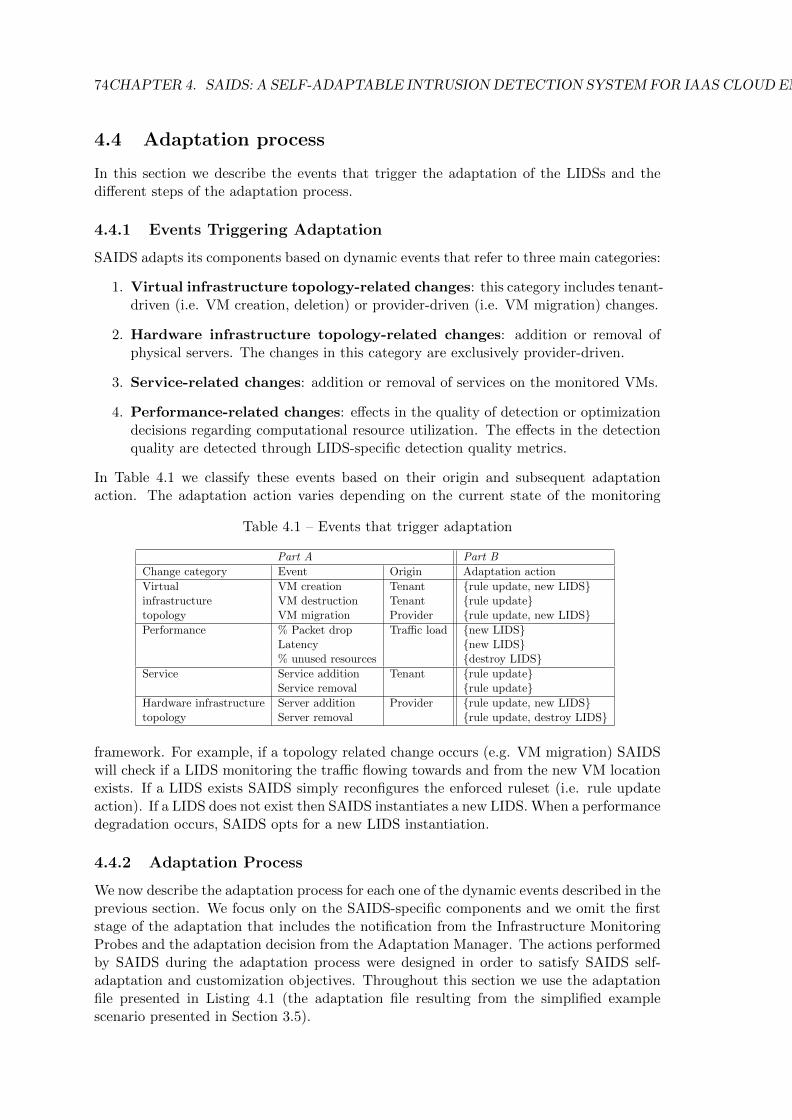
74CHAPTER 4. SAIDS: A SELF-ADAPTABLE INTRUSION DETECTION SYSTEM FOR IAAS CLOUD ENVIRONMENTS
4.4 Adaptation process
In this section we describe the events that trigger the adaptation of the LIDSs and thedifferent steps of the adaptation process.
4.4.1 Events Triggering Adaptation
SAIDS adapts its components based on dynamic events that refer to three main categories:
1. Virtual infrastructure topology-related changes: this category includes tenant-driven (i.e. VM creation, deletion) or provider-driven (i.e. VM migration) changes.
2. Hardware infrastructure topology-related changes: addition or removal ofphysical servers. The changes in this category are exclusively provider-driven.
3. Service-related changes: addition or removal of services on the monitored VMs.
4. Performance-related changes: effects in the quality of detection or optimizationdecisions regarding computational resource utilization. The effects in the detectionquality are detected through LIDS-specific detection quality metrics.
In Table 4.1 we classify these events based on their origin and subsequent adaptationaction. The adaptation action varies depending on the current state of the monitoring
Table 4.1 – Events that trigger adaptation
Part A Part B
Change category Event Origin Adaptation action
Virtual VM creation Tenant {rule update, new LIDS}infrastructure VM destruction Tenant {rule update}topology VM migration Provider {rule update, new LIDS}Performance % Packet drop Traffic load {new LIDS}
Latency {new LIDS}% unused resources {destroy LIDS}
Service Service addition Tenant {rule update}Service removal {rule update}
Hardware infrastructure Server addition Provider {rule update, new LIDS}topology Server removal {rule update, destroy LIDS}
framework. For example, if a topology related change occurs (e.g. VM migration) SAIDSwill check if a LIDS monitoring the traffic flowing towards and from the new VM locationexists. If a LIDS exists SAIDS simply reconfigures the enforced ruleset (i.e. rule updateaction). If a LIDS does not exist then SAIDS instantiates a new LIDS. When a performancedegradation occurs, SAIDS opts for a new LIDS instantiation.
4.4.2 Adaptation Process
We now describe the adaptation process for each one of the dynamic events described in theprevious section. We focus only on the SAIDS-specific components and we omit the firststage of the adaptation that includes the notification from the Infrastructure MonitoringProbes and the adaptation decision from the Adaptation Manager. The actions performedby SAIDS during the adaptation process were designed in order to satisfy SAIDS self-adaptation and customization objectives. Throughout this section we use the adaptationfile presented in Listing 4.1 (the adaptation file resulting from the simplified examplescenario presented in Section 3.5).

4.4. ADAPTATION PROCESS 75
4.4.3 Topology-Related Change
Once the Master Adaptation Driver (MAD) receives the adaptation parameters from theAdaptation Manager two steps are performed:
1. It checks whether the affected LIDS is running or not. If it is not running then theMAD starts a new LIDS and reconfigures the traffic distribution on the local switchof the node hosting the LIDS in order for the newly instantiated sensor to access thetraffic flowing towards and from the affected VM.
2. The MAD translates the adaptation parameters to LIDS-specific configuration pa-rameters and creates a new LIDS-specific configuration file. The configuration filecontains the list of rule categories that need to be activated in the LIDS in order tosuccessfully monitor the list of services running inside the affected VM. In our exam-ple the MAD partially matches the adaptation argument to the rule category namein order to find the right rule categories that need to be activated. A partial matchis found when the adaptation argument is contained in the rule category name (e.g.worm in emerging-worm.rules). Consequently, for the worm adaptation argumentthe emerging-worm.rules category will be activated while for the sqld argument theemerging-sql.rules will be activated. In case a partial match is not found, MAD usesthe second file from SAIDS input set (see Section 4.3), which is a LIDS-specific file,located in the MAD node, to translate the adaptation argument to rule categorynames. The file only features rule categories that can not be partially matched tothe adaptation argument (e.g. apache2 or ssh). A snippet of this file can be foundin Listing 4.2:
Listing 4.2 – The userservice.conf file
1 mail emerging−pop3 . ru l e s , emerging−smtp . r u l e s2 apache2 , nginx http−events . ru l e s , emerging−web server . ru l e s , emerging−
web sp e c i f i c app s . r u l e s3 sshd emerging−s h e l l c o d e . ru l e s , emerging−t e l n e t . r u l e s
In the newly created suricata configuration file the following rule categories will beactivated: (a) http-events.rules, emerging-web server.rules,emerging-web specific apps.rules for the web server, (b) emerging-shellcode.rules,emerging-telnet.rules for the ssh daemon and finally, (c) emerging-sql.rules for theSQL database. A part of the resulting LIDS configuration file can be found in List-ing 4.3:
Listing 4.3 – The suricata.yaml file
1 #RULE BLOCK2 # − decoder−events . r u l e s # ava i l a b l e in s u r i c a t a sour c e s under r u l e s
d i r3 # − stream−events . r u l e s # ava i l a b l e in s u r i c a t a sour c e s under r u l e s
d i r4 − http−events . r u l e s # ava i l a b l e in s u r i c a t a sour c e s under r u l e s
d i r5 # − smtp−events . r u l e s # ava i l a b l e in s u r i c a t a sour c e s under r u l e s
d i r6 # − dns−events . r u l e s # ava i l a b l e in s u r i c a t a sour c e s under r u l e s
d i r7 # − t l s−events . r u l e s # ava i l a b l e in s u r i c a t a sour c e s under r u l e s
d i r8 # − emerging−us e r ag en t s . r u l e s
76CHAPTER 4. SAIDS: A SELF-ADAPTABLE INTRUSION DETECTION SYSTEM FOR IAAS CLOUD ENVIRONMENTS
9 # − emerging−voip . r u l e s10 # − emerging−web c l i en t . r u l e s11 # − to r . r u l e s12 − emerging−web server . r u l e s13 − emerging−web sp e c i f i c app s . r u l e s14 − emerging−worm . r u l e s15 − emerging−s h e l l c o d e . r u l e s16 − emerging−t e l n e t . r u l e s17 − emerging−s q l . r u l e s
3. As a last step, the MAD notifies the AW, which is locally installed inside the LIDS,that a new configuration file exists and the IDS needs to be reconfigured. Uponreceiving the notification, the AW checks whether the detection process is runningand initialises a reload of the newly created configuration file. Once the reloadis complete (i.e. the LIDS has been adapted) the AW notifies the MAD that theadaptation process was completed successfully. In case the AW notifies the MAD thatthe adaptation process failed, for example due to a crash of the detection processor an unsuccessful reload of the enforced ruleset, the MAD propagates the eventto the AM which then notifies the safety mechanism that the VM should not yetbe resumed in the new location. Depending on the type of failure the followingstrategy is adopted: first, the AW will try to restart the detection process (or reloadthe enforced ruleset in the event of a reload failure). If it fails, it propagates theinformation to the MAD, which in turn instantiates a new LIDS, reconfigures trafficdistribution appropriately and destroys the failed LIDS instance. The number of triesthat the AW will execute before a new LIDS needs to be instantiated are decided bythe MAD. The AW guarantees that during the reconfiguration phase, the LIDS willcontinue to operate seamlessly, thus no traffic remains uninspected.
4. Finally, the MAD notifies the Adaptation Manager that the adaptation request wasserved. The AM in turn notifies the safety mechanism that the VM can be safelyresumed.
4.4.4 Traffic-Related Change
In order to detect degradation in the performance of an LIDS the MAD periodicallyqueries the AW for LIDS-specific performance metrics (e.g. packet drop rate). Once theperformance metric exceeds a predefined threshold, the MAD instantiates a new LIDS,with identical configuration parameters, and reconfigures the traffic distribution on thelocal switch so that the load is balanced between the two LIDSs. Currently the MADcan redistribute traffic load only on a VM basis (i.e. send all the traffic from and to aparticular VM to a specific LIDS).
4.4.5 Service-Related Change
The adaptation process is the same as a topology related change. Since SAIDS doesnot feature any mechanism for automatic discovery of new services in the deployed VMs,we rely on the tenants in order to notify SAIDS for service-related events (through ourframework’s dedicated API).
So far the description of the adaptation process focuses on the side of the monitoringprobes. Although LIDS reconfiguration is essential for preserving an adequate level ofdetection in the virtual infrastructure, gaining access to the right portion of the traffic is

4.5. IMPLEMENTATION 77
also required. Each time a topology-related change occurs (e.g. VM creation or migration),the Mirror Worker is responsible for checking whether a traffic endpoint from the localswitch on the compute node to the local switch of the IIDS node exists, and if not createsit. This strategy applies to hardware-related changes as well.
4.5 Implementation
We have implemented a prototype of SAIDS from scratch using the KVM [27] hypervisoron a private cloud. Our cloud was deployed on OpenStack [32] and we used Open vSwitch(OvS) [137] as a multilayer virtual switch. To segregate VMs that belong to differenttenant networks we utilised Generic Routing Encapsulation (GRE) tunnels. A span tunnelendpoint was created for mirroring traffic in the virtual switches to the LIDSs node. Inthis section we discuss the main implementation aspects of each SAIDS component.
Local Intrusion Detection Sensors: we deploy each LIDS inside a dedicatedDocker [45] container. Since the LIDS only runs the detection process and does notrequire a full operating system, we opt for containers in order to achieve minimal starttime. Containers are also a suitable lightweight solution for achieving isolation betweendifferent detection processes. Currently our prototype features 2 different legacy networkIDSs: Snort [93] and Suricata [94]. Each container hosts an IDS process and an Adapta-tion Worker responsible for managing that process. For providing access to the mirroredtraffic for the LIDSs we use the ovs-docker utility. Ovs-docker allows docker containersto be plugged on OvS-created bridges. It interacts with the virtual switch on the nodehosting the LIDSs and creates one network tap per container. We select signature-basedLIDSs as they are the ones requiring zero training time. We utilise OpenFlow [48] rules fordistributing traffic between LIDSs. Depending on the monitoring strategy selected (e.g.one LIDS monitoring the traffic that flows towards and from a particular compute node),the traffic is distributed based on the tunnel source address of the GRE tunnel transferringthe monitored traffic.
Adaptation Worker: We have created a unified version of the AW that is ableto handle the signature-based LIDSs that are supported in our prototype (i.e. Suricataand Snort). The AW communicates with the Master Adaptation Driver for receivingreconfiguration requests and reporting back on the reconfiguration status using a sharedfolder. The AW places the shared folder under surveillance for specific events (file creationand modification) using the Inotify Linux utility [139], a tool for detecting changes infilesystems and reporting them back to applications. Once the event is triggered theAW loads this new configuration file (so the new ruleset can be enforced) and calls thelive rule swap functionality available in both Suricata and Snort IDSs in order to liveupdate (i.e. without having to restart the LIDS) the enforced ruleset. The live rule swapoperation allows a user to update the enforced ruleset without stopping the IDS itself (aSIGUSR2 is sent to the detection process). MAD relies on this functionality, consequentlythe LIDS remains operational even during the actual reconfiguration. The AW ensures thatthe new ruleset has been loaded by continuously monitoring the log file for a log indicatingthat the new ruleset has been reloaded. Once the reload is complete the AW notifies theMAD by creating a dedicated file in the shared folder. The AW was implemented inPython.
Master Adaptation Driver: For enabling managing the lifecycle and reconfigurationof multiple LIDSs MAD was implemented using a multithreaded approach. MAD createsa unique folder per LIDS and uses a dedicated thread to watch this folder for changes(again using the inotify utility). Once an adaptation request arrives from the AM (i.e.
78CHAPTER 4. SAIDS: A SELF-ADAPTABLE INTRUSION DETECTION SYSTEM FOR IAAS CLOUD ENVIRONMENTS
a file containing the adaptation parameters is created in the watched folder) the threadstarts the reconfiguration process. The MAD features IDS specific configuration files fortranslating the adaptation parameters to rule categories. If the LIDS is not started yet,the thread starts it, creates a port for it on the virtual switch using the add-port commandfrom ovs-docker and finally redirects the appropriate mirrored traffic to the created port.The last part is done by creating a dedicated OpenFlow rule that redirects the traffic fromthe GRE tunnel endpoint to the LIDS port.
For tracking the resource consumption of each LIDS sensor the MAD features a specialfunction called docker stats monitor. First, it obtains the container’s ID. Then it periodi-cally queries the cgroup of that particular ID for different runtime metrics: CPU, I/O andResident Set Size memory. The MAD also inspects externally the packet drop rate for aparticular LIDS container by collecting interface level packet drop count from inside thecontainer namespace. The MAD was implemented in Python.
Mirror Worker: It checks whether a GRE tunnel for mirroring the traffic flowingtowards and from a group of VMs to the corresponding LIDS exists. If not the MW createsit. The IP of the LIDS along with the VMs IDs and the port name of the VM on thedestination node are sent by the Adaptation Manager. Once the AW receives the OvSport name, it uses the list interface OvS command giving the port name as input in orderto extract the port’s id. The MW was implemented in Python.
Safety Mechanism: we implement the safety mechanism by placing a dedicated hookinside the plug vifs Nova function which is executed on compute nodes. The plug vifsfunction is responsible for creating the virtual interface for the VM on the OvS bridgeof the destination node. The hook halts the virtual interface creation until the LIDSreconfiguration has been completed. By placing the hook inside the function we makesure that network connectivity for the VM is not enabled until the adaptation is complete.We select the plug vifs function because it is executed in both VM creation and migrationevents. The safety mechanism was implemented in Python.
4.6 Evaluation
After presenting the most important implementation aspects of SAIDS we now presentthe evaluation of our prototype. We first detail the objectives of our evaluation plan alongwith our experimentation methodology. Finally, we discuss the obtained results along withlimitations.
4.6.1 Objectives of the Evaluation
The main goal of SAIDS is to adapt the LIDSs while guaranteeing an adequate levelof security, combined with adequate performance (in terms of reaction time for a fulladaptation loop) and minimised cost both for tenants and the provider. We now detailthe factors that affect each objective.
4.6.1.1 Performance
The performance objective refers to two different aspects: adaptation speed and scalability.
4.6.1.1.1 Adaptation Speed: Here we refer to the time required for SAIDS to per-form a full adaptation loop, from the moment a dynamic event occurs until all involvedLIDSs are successfully reconfigured. In order to have an exact calculation of the overalltime we need to answer the following questions:

4.6. EVALUATION 79
1. What are the different SAIDS components that are involved in each adaptation loop?Five SAIDS components are mandatorily involved in each adaptation loop: theAdaptation Manager, the Master Adaptation Driver, the Adaptation Worker, theMirror Worker and the safety mechanism. Obviously, the overall time depends onthe different tasks that each component has to complete.
2. What are the tasks performed by each component?
• Adaptation Manager: makes the adaptation decision and sends the adaptationarguments to the Master Adaptation Driver.
• Master Adaptation Driver: checks if the LIDS container is running and depend-ing on the outcome, directly proceeds in generating the adapted configurationfile or first starts a new LIDS container and configures traffic distribution.
• Adaptation Worker: conducts the live rule update in the LIDS container.
• Mirror Worker: checks whether a traffic endpoint from the compute node host-ing the VM to the node hosting the LIDSs exists and if not creates it.
• Safety Mechanism: guarantees that in the case of a VM creation or migrationthe VM does not enter an active state until the reconfiguration of the LIDS hasbeen completed successfully.
Different factors affect the completion time of each task, which leads us to the nextquestion:
3. Which factors affect the execution time of each task?
• Adaptation Manager: the number of the adaptation arguments affects the sizeof the file and consequently the time required to send it to the MAD on theLIDS node. The number of the adaptation arguments depends on the numberof services running inside the monitored VMs and the number of additionalmonitoring rules that the tenant has requested.
• Master Adaptation Driver: the number of rules that need to be activated/de-activated affects the time required to regenerate the LIDS configuration file.The time required for the remaining tasks is not affected by the adaptationarguments.
• Adaptation Worker: the number of rules that are added affects the overall timerequired to reload the enforced ruleset.
• Mirror Worker: since the MW needs to create a single tunnelling endpoint(which translates to executing two OvS commands, one for identifying the portnumber of the VM’s port and one for creating the tunnel itself) the MW exe-cution time is expected to be constant.
• Safety Mechanism: the waiting time introduced by the safety mechanism inresuming the VM is equal to the time remaining to complete the adaptationprocess when the Nova function plug vifs is called on the VM destination node.Consequently, the factors that affect the completion time of the four otherSAIDS components indirectly affect the execution time of the safety mechanism.
We now present the second performance objective.

80CHAPTER 4. SAIDS: A SELF-ADAPTABLE INTRUSION DETECTION SYSTEM FOR IAAS CLOUD ENVIRONMENTS
4.6.1.1.2 Scalability: We want to evaluate how many adaptation requests SAIDS cansuccessfully serve in parallel. In order to achieve this we need to answer the two followingquestions:
1. How many full adaptation loops can SAIDS handle in parallel? Each loop is com-posed of three different levels: The Adaptation Manager, the Master AdaptationDriver and finally the Adaptation Worker with the LIDS (the level of the AW doesnot scale since the design pairs a single AW with a single LIDS). The evaluation ofthe overall scalability of SAIDS should be composed of the scalability evaluation ofeach one of the adaptation levels. Consequently, we need to calculate: (a) How manyMADs can the Adaptation Manager handle in parallel? This is the scalability resultof the first level of adaptation (from the AM to different MADs). To achieve this wecalculate the maximum number of MADs that the AM can handle in parallel. Forthis phase we only vary the number of MADs. (b) How many LIDSs can a MADhandle in parallel? This is the scalability result of the second level of the adaptation(from a MAD to the LIDSs). To achieve this we need to consider the case wherethe number of tasks that a MAD needs to perform per LIDS is maximized. Thiscase essentially requires the MAD to spawn a new LIDS and configure the trafficdistribution on the local switch, for each adaptation request. We examine only thiscase as the one requiring the maximum effort on the MAD side. Since the focusof the experiment is on creating new LlDSs, rather than reconfiguring the enforcedruleset of existing ones, we only activate one rule category per IDS. The number ofrule categories that are activated does not change the size of the LIDS configurationfile (see example in Listing 4.3) thus the time required for the MAD to generate itis not impacted. Moreover, since the MAD operations are asynchronous, the timerequired to load the rules in each LIDS does not affect the MAD scalability. For thisphase of the experiment we only vary the number of LIDSs.
2. What is the overhead imposed by the multiple parallel requests in the execution timeof each adaptation loop? We would like to identify the impact of parallelism on thetime required to complete each adaptation loop. The reaction time of two SAIDScomponents (i.e. Adaptation Manager and Master Adaptation Driver) is directlyaffected by the number of parallel requests. We compute the overhead (in seconds)in the reaction time of the two components.
4.6.1.2 Cost
We examine the associated penalties on deploying SAIDS both from the tenants and theprovider’s objective. From the provider’s perspective we calculate the overhead imposed bySAIDS to normal cloud operations (e.g. VM migration) while for the tenants we examineif SAIDS imposes any overhead in the performance of tenant applications.
• Provider-side cost: namely, What is the overhead (in seconds) introduced bySAIDS to a normal cloud operation like a VM migration?
• Tenant-side cost: since SAIDS monitoring is performed by network based IDSsthat work on mirrored traffic, SAIDS deployment does not directly affect tenantapplications regardless of their profile (no latency is induced in the production net-work). The traffic mirroring itself can indirectly affect the applications running onthe SAIDS-monitored node due to CPU consumption and physical network band-width usage (although this penalty is inherent of the mirroring technique and not
4.6. EVALUATION 81
SAIDS itself). The only SAIDS related cost on individual tenant applications isrelated to the VM downtime when normal cloud operations occur.
4.6.1.3 Security and Correctness
Since one of the main SAIDS objectives is to guarantee an adequate level of detectionduring the adaptation time, it is clear that we need to examine whether malicious traffic issuccessfully identified even when the LIDSs are being reconfigured. Furthermore, we needto certify that SAIDS does not affect the detection capabilities of the adapted LIDSs andthat the adaptation result is correct. We focus on the following questions:
• Are the added rules correct and operational?
• Are there any packets dropped during the adaptation time?
• Can SAIDS detect an attack that occurs during the adaptation time?
• Does SAIDS add any security flaw in the adaptation process itself or in the provider’sinfrastructure? in Section 4.3 we have already justified why our design choices donot add any flaws in the adaptation process and in the provider’s infrastructure.
After presenting the objectives of our evaluation process, we now detail the experimentalscenarios used to perform the evaluation of our SAIDS prototype.
4.6.2 Experimentation Methodology
This section describes in detail the experimental scenarios used in order to evaluate SAIDSprototype. The scenarios were designed for addressing multiple evaluation objectives si-multaneously. We select VM migration as a representative cloud operation that includesVM creation and deletion. For examining the security and correctness of SAIDS, we selecta web server as use case.
4.6.2.1 VM Migration
The VM migration scenario simultaneously addresses the performance and cost objectives(only the provider-associated cost of deploying SAIDS). We aim at calculating the over-head imposed by deploying SAIDS in a VM migration. In this scenario we calculate themigration time of a monitored VM under two different workload cases: 1. an idle VM,no workload running in the migrated VM (idle VM) and 2. a memory-intensive workloadrunning in the migrated VM. The overall migration time depends on two factors: thememory size of the migrated VM and the workload running inside the migrated VM. Theworkload cases represent two different situations, the first one (i.e. idle VM), with mini-mum migration time, consequently any overhead imposed by SAIDS is maximised whilethe second one (i.e. memory intensive workload), with maximum migration time, henceany overhead imposed by SAIDS is minimised. In both cases we examine all possibleadaptation options:
• a corresponding LIDS already exists and is running on a dedicated node, thus SAIDSonly needs to reconfigure the enforced ruleset.
• SAIDS needs to start the corresponding LIDS, create a port for it on the virtualswitch, and redirect the mirrored traffic coming from the destination node of theVM to the LIDS port. Furthermore, SAIDS needs to check whether a tunnel for the

82CHAPTER 4. SAIDS: A SELF-ADAPTABLE INTRUSION DETECTION SYSTEM FOR IAAS CLOUD ENVIRONMENTS
mirrored traffic from the destination node of the VM to the LIDS node exists and ifnot create it.
In each option we calculate the reaction time of each SAIDS component.
4.6.2.2 Multiple LIDSs and Multiple MADs
This scenario focuses on the scalability objective of our evaluation plan. The multipleLIDSs and multiple MADs scenario examines the ability of SAIDS to handle multipleadaptation requests in parallel. SAIDS’s scalability is examined at two different levels:the Master Adaptation Driver and the Adaptation Manager. At the Master AdaptationDriver level, we calculate the total reaction time as well as the reaction time of each phase(ruleset configuration, LIDS creation, traffic distribution). We compare the results withthe adaptation of a single LIDS and calculate the scalability overhead. The only varyingparameter in this experiment is the number of LIDS.
For the Adaptation Manager level we calculate how many different Master AdaptationDrivers (each one with maximized load) an can AM handle in parallel. Each MAD residesin a different node and requires a dedicated secure connection in order to transmit theadaptation arguments. We calculate the mean reaction time of the AM and we compareit with a single MAD approach in order to calculate the scalability overhead.
For the evaluation, we simulate a large number of nodes using containers and we placeeach MAD in a separate container with a dedicated IP address. All containers are placedon the same physical node. Since each container is a completely isolated environment, theAM perceives it as a dedicated node and still needs to create a dedicated secure connectionper MAD. Due to memory restrictions (our node has 24GB of memory) no LIDS is runinside the containers. Since the MAD operations are asynchronous the fact that no LIDSis run does not affect the result.
In SAIDS, an adaptation request concerning a single LIDS is represented by a filecontaining the adaptation arguments (one file per LIDS is sent from the AM to the MADresponsible for the adapted LIDS). Consequently, in order to simulate the maximum num-ber of adaptation requests per MAD, we take the results from the first phase of theexperiment (i.e. the maximum number of LIDSs that a single MAD can handle) and wesend the same number of files containing adaptation arguments to each MAD. The varyingparameter in this experiment is the number of MADs.
4.6.2.3 Web Server
In this scenario we examine SAIDS ability to guarantee an adequate level of detection evenduring the adaptation process. For this purpose we migrate a web server and we launchmultiple SQL injection attacks during the migration period. In the set up created for thisscenario we have two different LIDSs (one monitoring the traffic in the source node andone monitoring the traffic in the destination node). The first LIDS is already configuredto detect SQL injection attacks while the second one is not. We expect that the secondLIDS will be able to detect the attacks after SAIDS adapts it. Depending on when in themigration phase the attack packets reach the victim VM we expect different outcomes.
Before presenting the different outcomes we briefly discuss the migration aspect thataffects the connectivity of the migrated VM. In each live migration the dirty memory pagesof the migrated VM are copied from the source to the destination node until a specificthreshold is reached, when the VM is momentarily paused the remaining memory pagesare copied and then the VM is resumed at the destination node. Until this threshold
4.6. EVALUATION 83
is reached the VM continues to be active on the source node, thus the virtual interfaceaccepting VM-related traffic is the one on the source node (consequently in our case it willbe monitored by the first LIDS). In parallel with the memory pages copy, a new virtualinterface for the VM is created on the destination node. After the interface is created andthe copy of the pages reaches the threshold, the VM is activated on the destination node,thus the traffic is now redirected on the new virtual interface (consequently in our case itis monitored by the new LIDS).
We now list the three different outcomes:
1. Attack packets reach the VM before the virtual interface has been created at thedestination node. Consequently, the packets will be inspected by the first LIDS. Weexpect the attack to be detected since the LIDS is already configured.
2. Attack packets reach the VM after the virtual interface has been created at thedestination node and SAIDS has successfully reconfigured the second LIDS. Weexpect the attack to be detected since the second LIDS is already reconfigured.
3. Attack packets reach the VM after the virtual interface has been created at thedestination node and SAIDS reconfiguration is on-going on the second LIDS. SinceSAIDS utilises the live rule swap functionality of a LIDS we expect the second LIDSto analyze the attack packets as soon as the new ruleset has been reloaded (the alertwill be generated once the new ruleset is enforced and the attack packets reach thesecond LIDS).
SAIDS features a safety mechanism that does not allow the VM to enter an active stateafter migration (i.e. on the destination node) before the LIDS reconfiguration has beencompleted. The safety mechanism guarantees that no packets will reach the VM beforethe new LIDS is successfully reconfigured.
Furthermore, for checking whether SAIDS causes the LIDS to drop packets during theadaptation process, we compare the number of packets reaching the virtual interface ofthe LIDS with the number of packets that the LIDS reports as captured.
4.6.3 Result Analysis
After presenting our evaluation scenarios and the objectives that they serve we now analyzethe obtained results.
4.6.3.1 Experimental Setup
To do our experiments, we deployed a data center on the Grid5000 experimentation plat-form. Our datacenter has 5 physical nodes: one controller, one network node, two com-pute nodes and one separate node for hosting the LIDSs. Each physical node has 24GB ofRAM and features two AMD Opteron processors (1.7Ghz, 4 cores each). The nodes run anUbuntu Server 14.04 operating system and are interconnected through a 1Gb/s network.The LIDSs gain access to the monitored traffic through mirror ports and GRE tunnels.The LIDSs in all experiments run a Suricata NIDS process. All the VMs deployed on thephysical nodes run an Ubuntu server 14.04 Operating System with 2 CPUs and 4 GB ofRAM. We perform 10 executions per experiment.

84CHAPTER 4. SAIDS: A SELF-ADAPTABLE INTRUSION DETECTION SYSTEM FOR IAAS CLOUD ENVIRONMENTS
4.6.3.2 VM Migration
To generate the memory-intensive workload we utilised bw mem wr from the LMBenchbenchmark suite [143] with a 1024MB working set. The working set is allocated, zeroedand then written as a series of 4 byte integers. In each adaptation we only add two new rulecategories that correspond to ssh traffic (emerging-shellcode.rules, emerging-telnet.rules).Since the VM is not executing a workload that generates traffic no other rules are neces-sary. In this scenario we aim at proving that SAIDS imposes negligible overhead in theVM migration. The results are shown in Figure 4.2. The imposed overhead in both cases
idle
memory-intensive
VM workload
0
10
20
30
40
50
Mig
rati
on t
ime (
s)
13.9
38.2
13.9
38.2
Without SAIDSWith SAIDS
Figure 4.2 – Migration time with and without SAIDS
(idle VM and VM with memory intensive workload) is 0.0s which validates our initialhypothesis that SAIDS imposes negligible overhead on typical cloud operations. A perphase breakdown of the two different adaptation cases (i.e. ruleset reconfiguration onlyand new LIDS with traffic distribution) is shown in Figures 4.3 and 4.4. In both cases
Migrationrequest
Controller Node
MAD Node
Adaptation Manager:Decide on adaptation
send adaptation arguments
Conf fileGeneration
Check ifIDS is
running
0.012s
0.13s 0.01s
LIDS
Rule reloadfinish
Rule reloadstart
4.0s
Send mirror arguments to
MW0.012s
Destination Node
VMresumed
13.9s
Figure 4.3 – Adaptation time breakdown when SAIDS only reconfigures the enforcedruleset inside the LIDS
the safety mechanism is enabled but the LIDS reconfiguration is completed much earlierthan when the plug vifs is called (4.14s and 0.97s respectively while the plug vifs functionis called always after the 10th second). Consequently no waiting time for resuming the

4.6. EVALUATION 85
Migrationrequest
Controller Node
MAD Node
Adaptation Manager:Decide on adaptation
send adaptation argumentsto MAD
Start new IDS,configure
trafficdistribution
Check ifIDS is
running
0.15s
0.13s 0.68s
LIDS
StartIDS
processDestinationNode
MW Create
gre tunnelconfiguremirroring
0.05s
Conf fileGeneration
LIDSseestraffic
0.14s
Send mirror arguments to
MW
VMresumed
13.9s
Figure 4.4 – Adaptation time breakdown when SAIDS has to start a new LIDS, distributetraffic and create a mirroring tunnel
VM is introduced. In the first case, where only a reconfiguration of the enforced ruleset isrequired, the time until the new ruleset is loaded is 4.14s (the MAD starts the reconfigu-ration process as soon as it receives the adaptation arguments). The AM uses the existingconnection in order to send the file with the adaptation arguments thus we include onlythe time to send the file in the overhead analysis. In the second case, where a new LIDSneeds to be instantiated, the time required until it gains access to the traffic is 0.97s (timefor the MAD to start the LIDS and reconfigure traffic: 0.82s + time for the AM to sendthe adaptation arguments: 0.15s – connection establishment + file transmission time).The creation of the tunnel endpoint in the VM destination node takes 0.19s (including thetime required for the AM to send the information to the AW which contains connectionestablishment and file transmission time). The overall time required for SAIDS to per-form a full adaptation loop in both cases, is much smaller than the overall migration time(13.9s for an idle VM and 38.2s for a VM with a memory intensive workload). Further-more, reconfiguring an existing IDS is a much heavier operation than starting a new one.This is due to the fact that during the reconfiguration process the AW needs to wait untilthe live rule swap is complete, which, depending on the number of newly added rules andpotential LIDS delay in flushing its logs, can be time consuming.
4.6.3.3 Multiple MADs and Multiple LIDSs
In order to create multiple adaptation events in parallel, we wrote a dedicated scriptthat simulates migration events by generating the same arguments that are sent to theAdaptation Manager by the Infrastructure Monitoring Probe in case of a VM migration(VM public IP, VM private IP, source and destination node, port on the virtual switch ofthe destination node).
4.6.3.3.1 MAD Scalability – Multiple LIDSs: During the first phase of our ex-periment we focus only on a single Master Adaptation Driver and compute the maximum

86CHAPTER 4. SAIDS: A SELF-ADAPTABLE INTRUSION DETECTION SYSTEM FOR IAAS CLOUD ENVIRONMENTS
number of LIDSs that it can handle in parallel. The setup of a single MAD instancehandling multiple LIDS is depicted in Figure 4.5.
Master AdaptationDriver
AdaptationWorker
Workerthread
….
LIDS LIDS LIDS LIDS
LIDS Node
….
Figure 4.5 – MAD scalability setup
Our results show that a single MAD instance located in a dedicated node with 24GBof RAM can handle up to 50 LIDS (each LIDS requires 460.1MB of RAM consequently 50is the maximum number of LIDS that the physical node of our testbed can handle beforeit’s memory capacity is reached). The average response time of the MAD agent underdifferent LIDS load is shown in Figure 4.6.
1 8 20 40 50Number of LIDS
0
2
4
6
8
10
12
14
MA
D r
esp
onse
tim
e (
s)
0.591.72
3.87
6.958.38
0.08
0.32
0.48
0.7
0.78
0.01
0.01
0.11
0.15
0.19
LIDS creationSwitch port creationTraffic redirection
Figure 4.6 – MAD response time
From the obtained results we identify that the task of spawning a new LIDS container,which implies interacting with the Docker daemon, is the most time consuming task.Even with 50 parallel LIDS spawning requests, which represent the maximum number ofSuricata containers that our physical node can accommodate, the mean overall reactiontime for SAIDS under maximum load is 9.41s, which is still significantly lower than the13.9s average migration time for an idle VM (see experiment Described in Section 4.6.3.2).Consequently, even if one of the 50 LIDS that are adapted is responsible for monitoring thetraffic flowing towards and from the migrated VM, still no overhead will be introduced inthe VM migration (the LIDS will be instantiated before the migration is completed). Notethat in the breakdown of the MAD phases, we did not include the time required for theMAD to produce the new LIDS configuration file and check whether a new LIDS is running,since their effect in the overall time is negligible (see explanation in Section 4.6.2.2).

4.6. EVALUATION 87
In a production environment, a usual deployment scenario includes assigning one coreper LIDS in order to maintain an adequate performance level (in terms of packet loss) forthe detection process. For simulating a production setup we tested SAIDS with 8 paralleladaptation requests (our machine has 8 cores). The mean overall time for MAD was 2.08swith individual breakdown of: LIDS creation 1.72s, switch port creation 0.32s and trafficredirection 0.01s.
4.6.3.3.2 Scalability of the AM – Multiple MADs: After obtaining the maximumnumber of LIDSs that a single MAD instance can handle in parallel in our testbed (50LlDS – 460.1 MB of RAM per LIDS in a node with 24GB of RAM) we now study thescalability in the response time of the Adaptation Manager. In our experiment, each AMworker thread needs to adapt all the LIDS belonging to a single MAD (50 LIDS). Weinstantiate up to 100 AM worker threads. The setup of a single AM instance handlingmultiple MADs is depicted in Figure 4.7.
Adaptation Manager
Workerthread
Master Adaptation
Driver ….
….
Figure 4.7 – AM scalability setup
In this scenario, the monitoring strategy selected assigns a single LIDS for monitoringthe traffic flowing towards and from a single VM (although this strategy is not optimal interms of provider-side costs we apply it for the scalability study). Consequently, in orderto generate the adaptation requests for the 50 LIDS of each thread, we use our scriptto simulate 50 dynamic events (e.g. VM migrations) for 50 different VMs. In order totarget the LIDS that belong to the same MAD instance that a worker thread is handling,all the VMs of a worker thread are migrated to the same destination node. In order toextract the arguments for each one of the 50 VMs that it is handling the worker threadneeds to parse the file where all the VM-related information is stored (vm info.xml). Forgenerating enough tasks for the worker threads the minimum number of VM entries in thisfile is computed as follows: maximum number of AM worker threads × number of VMsper thread. In this scenario we instantiate up to 100 AM worker threads consequently theminimum number of entries in the vm info.xml : 100 × 50 = 5000. The arguments forthe adaptation of each LIDS are written to a separate file (see an example in Listing 4.1,adaptation args.txt). Each file has a size of 219 bytes.
Then, the worker thread opens a single secure connection and sends all 50 files (oneper LIDS) to the MAD responsible for the 50 LIDS. Finally, the worker thread opens a

88CHAPTER 4. SAIDS: A SELF-ADAPTABLE INTRUSION DETECTION SYSTEM FOR IAAS CLOUD ENVIRONMENTS
secure connection with the destination node of the migrated VMs and sends the necessaryinformation in a file to the MW. Note that since in our simulation all VMs of a singleworker thread are migrated to the same compute node, only one file is needed. Indeed,the target of this experiment is not to evaluate the scalability of the AM with respect tothe number of compute nodes. This optimization allows us to gain a better insight in thescalability of the AM with respect to the number of MADs.
The results are presented in Figure 4.8. As the results demonstrate, the phase that
1 10 20 40 50 100Number of MADs
0.0
0.2
0.4
0.6
0.8
1.0
AM
resp
onse
tim
e (
s)
0.011 0.009 0.009 0.009 0.008 0.009
0.13 0.15 0.15 0.16 0.17 0.18
0.28 0.28 0.28 0.28 0.28 0.28
0.130.15 0.15 0.16 0.17 0.180.012
0.012 0.012 0.012 0.012 0.012
Adaptation decisionLIDS node connectionSend adaptation argsDest node connectionSend mirror args
Figure 4.8 – AM response time
is most affected by increasing the load of the MADs for the AM is the establishment ofthe secure connection. That is due to the fact that each MAD is located in a differentcontainer with a different IP address consequently a separate secure connection is necessary(multiplexing is not possible). We measure the time to send the adaptation arguments (i.e.essentially the time required to send the 50 adaptation files) on the AM side. Since wedo not wait for confirmation from each MAD instance that it received the files, no delaydue to network contention is observed in the result. However, since all MAD instances areessentially run on different containers on the same node, some delay in the ssh connectionestablishment due to the number of processes running on the node could be observed. Thelatter makes the result of our experiment a pessimistic outcome compared to a real worldscenario where each MAD instance would be run in a separate less loaded node. Sincethe VM-related information for all the VMs is located in a single file the multi-threadingapproach does not significantly decrease the adaptation decision time (as opposed to thecase of one file per VM, where each worker thread needs to parse a file with only one entryinstead of 5000).
Our results demonstrate that a single AM instance can handle up to 5000 LIDS in-stances while the per-thread response time remains under 1s. The limit in the numberof LIDS instances results only from the memory capacity of the testbed used to conductour experiments. The number of instances could be increased, if SAIDS is deployed in adifferent setup where the memory capacity of production nodes is significantly larger than24 GB of RAM per node.
For computing the resource consumption of an AM in terms of CPU and memoryhandling multiple MADs we used the pidstat tool from the sysstat suite [144], a toolused for monitoring the resource consumption of a specific task running in an OS. Ineach experiment we ask the first worker thread to launch pidstat immediately after itreceives the adaptation arguments and we terminate the monitoring after the last workerthread has completed its tasks. With this strategy we make sure that we only compute

4.6. EVALUATION 89
the resource consumption of all the worker threads during the actual adaptation process.Since all the adaptation tasks in each adaptation request are performed by the workerthread responsible for that adaptation request, no other SAIDS-related process consumesresources. We set the monitoring interval at 1s. The results are shown in Table 4.2.
Table 4.2 – Resource consumption of the AM component
Number of MADs Usr% Sys% CPU% Memory (MB)
10 17.19 2.29 19.57 188.88
20 23.20 3.26 26.46 188.81
40 25.0 3.60 29.40 188.69
50 26.93 3.76 30.69 188.31
100 28.4 3.97 32.43 188.93
The increase in the CPU usage when the number of AM worker threads increases isdue to the fact that starting a new ssh session imposes an one-time CPU penalty (duringthe connection establishment due to the cryptographic key exchange). Our measurementscompute the worst-case scenario for each worker thread which is to establish a new con-nection. The CPU usage is expected to decrease in average-case scenarios where SAIDSneeds to reconfigure an existing LIDS, thus it can use an already established connectionfor sending the file containing the adaptation arguments.
4.6.3.4 Correctness Analysis
For the web server scenario we installed WordPress on the target VM and we used Metas-ploit suite [145] for launching SQL injection attacks. We have created our own customSQL injection rule which is included in the local.rules file (this file stores the user-definedrules in both Snort and Suricata LIDS). A snipet of the file can be found in Listing 4.4:
Listing 4.4 – The local.rules file
1 a l e r t tcp any any −> $HOMENET any (msg : ”WP Sql I n j e c t i o n Attack ” ; content: ”INSERT INTO wp users ” ; s i d : 1000017; rev : 1 ; )
The first LIDS, which monitors the traffic flowing towards and from the source computenode is configured to detect SQL injection attempts (the custom rule is activated), whilethe second LIDS, which monitors the traffic that flows towards and from the destinationnode, is not configured (the custom rule is deactivated). In order to cover all three pos-sibilities for the arrival time of the attack packet (before the virtual interface migration– attack packets are processed by the old LIDS, after the virtual interface migration butbefore the new LIDS reconfiguration and finally after the virtual interface migration andafter the LIDS reconfiguration) we launch 10 consecutive attacks at the beginning of theVM migration.
4.6.3.4.1 Attack packets arrive before the creation of the virtual interface ofthe target VM on the destination node: In this case the traffic is processed by thefirst LIDS, so the attack is detected and an alert is generated.
4.6.3.4.2 Attack packets arrive after the creation of the virtual interface ofthe target VM on the destination node and after the second LIDS has beensuccessfully reconfigured by SAIDS: In this case the enforced ruleset in the second

90CHAPTER 4. SAIDS: A SELF-ADAPTABLE INTRUSION DETECTION SYSTEM FOR IAAS CLOUD ENVIRONMENTS
LIDS is already reconfigured to include the custom SQL injection signature, so the attackis detected and an alert is generated.
4.6.3.4.3 Attack packets arrive after the creation of the virtual interface of thetarget VM on the destination node but before the second LIDS has been suc-cessfully reconfigured by SAIDS: In our strategy, the LIDS reconfiguration startsimmediately after the migration command is received by the cloud API and is executedin parallel with the migration. A full adaptation cycle from SAIDS requires either 4.14(existing LIDS reconfiguration) or 0.97s (new LIDS deployment) while the migration ofthe target VM requires in the best case scenario (idle VM) 13.9s (see experiment describedin Section 4.6.3.2). In this case the migration of the virtual interface of the target VM(executed by the plug vifs function) occurs always after the 10th second in the migrationcycle. As a result, the second LIDS reconfiguration has been completed before the migra-tion of the virtual interface of the target VM occurs. Consequently, the SAIDS adaptationcycle has already been completed and the LIDS has already been reconfigured. Indeed,attack packets never reach the new virtual interface on the destination node before SAIDSreconfiguration is complete.
For the two cases that refer to the second LIDS (see Sections 4.6.3.4.2 and 4.6.3.4.3),the number of packets that arrive in the virtual interface of the LIDS container is identicalto the number of packets reported by the Suricata process as captured, consequently nopackets are dropped during the reconfiguration phase. We chose to compare the number ofpackets reported by the Suricata process with the number of packets received by the LIDScontainer as comparison of the number of packets reported in any previous stage (e.g.with the number of packets copied to the mirror interface) may have included non-SAIDS-related packet loss. After analyzing our obtained results we now discuss the limitations ofSAIDS.
4.6.3.5 Limitations
SAIDS uses signature-based network IDSs and as such suffers from the inherent limitationsof this type of intrusion detection. Therefore, SAIDS cannot detect unknown attacks forwhich a corresponding signature (i.e. rule) does not exist. Furthermore, since SAIDSworks on a copy of the traffic, an additional mirror-induced delay is imposed between thetime an attack reaches the target VM and the time when the alert is raised from the LIDS.
Regarding the connection between different SAIDS components, according to our scal-ability study, a secure connection per MAD is required. This could lead to network con-tention in a real production environment where thousands of MAD nodes are deployed.
In the scenario described in Section 4.6.3.2 we saw that SAIDS imposes negligible over-head for average-sized VMs (4GB and higher). Since the LIDS reconfiguration is completedbefore the VM migration is completed in the destination node, the safety mechanism doesnot have to halt the VM from resuming. However, SAIDS could impose some overhead inmigration operations in cases of very light workload where the overall migration time isless than 4.14s (i.e. the time required for SAIDS to reconfigure an existing LIDS).
4.7 Summary
In this chapter we presented SAIDS, the first instantiation of our self-adaptable securitymonitoring framework. SAIDS is a self-adaptable network intrusion detection system that
4.7. SUMMARY 91
satisfies four main objectives: 1. self-adaptation, 2. tenant-driven customization, 3. scala-bility and 4. security. SAIDS is able to adapt its components based on different types ofdynamic events in the cloud infrastructure. Depending on the type of the event SAIDScan alter the configuration parameters of existing security probes or instantiate new ones.A detailed description of the adaptation process along with the role of each SAIDS com-ponent was presented.
We evaluated SAIDS under different scenarios in order to calculate the overhead of ourapproach in normal cloud operations, such as VM migration and we prove that SAIDSimposes negligible overhead in a VM migration. Furthermore, we evaluated the scalabilityand security/correctness of our approach with dedicated simulation scenarios. Scalabilitywas evaluated in two different levels (from AM to multiple MADs and from a MAD tomultiple LIDSs). Due to memory size restrictions imposed by our testbed the maximumnumber of LIDS that a single MAD can handle in parallel is 50 while the maximum numberof MADs that a single AM can handle is 100. Overall SAIDS can handle up to 5000 LIDSin our current testbed, while this number could be increased making our solution suitablefor a large scale cloud infrastructure. We have shown that SAIDS is able to detect attackswhile handling dynamic events (e.g. VM migration) and is able to remain operational evenduring the adaptation process.
The contribution presented in this chapter was focused on intrusion detection. Thenext chapter presents the second instantiation of our security monitoring framework, AL-SAFE and is focused on intrusion prevention.

92CHAPTER 4. SAIDS: A SELF-ADAPTABLE INTRUSION DETECTION SYSTEM FOR IAAS CLOUD ENVIRONMENTS
Chapter 5
AL-SAFE: A SecureSelf-Adaptable Application-LevelFirewall for IaaS Clouds
In this chapter we present the second instantiation of our framework which focuses on adifferent type of security component, the firewall. AL-SAFE is a secure application-levelintrospection-based firewall designed to cope with the dynamic nature of an IaaS cloudinfrastructure. This contribution was published in [146]. In Section 5.1 we motivate theneed for securing application-level firewalls and we present a justification of our designchoices regarding AL-SAFE. The system and threat models that we adopted along withindividual component description are presented in Section 5.2. Section 5.3 presents theadaptation process while implementation details are discussed in Section 5.4. Our evalua-tion strategy along with obtained results are presented in Section 5.5. Finally Section 5.7concludes this chapter by listing key observations.
5.1 Requirements
Application-level firewalls are an important part of cloud-hosted information systems sincethey provide traffic filtering based on the type of applications deployed in a virtual infras-tructure. However, they are subject to attacks originating both from inside and outsidethe cloud infrastructure. In this thesis, we aim at designing a secure application-level fire-wall for cloud-hosted information systems. In a cloud infrastructure, two security domainsexists: One is concerned with traffic that flows between VMs inside the virtual infrastruc-ture (that might belong to the same or different tenants) while the other is concerned withtraffic that flows between the outside world and the virtual infrastructure. Consequently,an application-level firewall should address both domains.
Furthermore, a cloud-tailored application-level firewall should take into account tenant-specific traffic filtering requirements and self-adapt its ruleset based on dynamic events thatoccur in a cloud infrastructure. In this section we elaborate on the need for securing acloud-tailored application-level firewall and we justify how AL-SAFE’s design addressesthis need. Furthermore, we detail the design principles of AL-SAFE and how they relateto the objectives of our self-adaptable security monitoring framework.
93

94CHAPTER 5. AL-SAFE: A SECURE SELF-ADAPTABLE APPLICATION-LEVEL FIREWALL FOR IAAS CLOUDS
5.1.1 Why Should we Secure an Application-level Firewall
In contrast to typical host- or network-level firewalls which filter network traffic based ona list of rules that use IP addresses and ports, application-level firewalls operate based ona white list of processes that are allowed to access the network. This fine-grained filter-ing is achievable because application-level firewalls run inside the host operating system,and thus have a complete overview of the running applications and associated processes.Unfortunately, in the conventional design of application-level firewalls, isolation betweenthe firewall and vulnerable applications is provided by the OS kernel, whose large attacksurface makes attacks disabling the firewall probable. Hence, we address the followingchallenge: Can we keep the same level of visibility while limiting the attack surface be-tween infected applications and a trusted, application-level firewall? In order to answerthis question, we designed AL-SAFE. In the following section we present in detail howAL-SAFE’s design addresses this impediment.
5.1.2 Security and Visibility
In order to address the issue of limiting the attack surface between the security device (i.e.the firewall) and a potentially compromised VM, we designed AL-SAFE to operate outsideof the virtual machine it is monitoring, in a completely separate domain. Leveraging virtualmachine introspection 2.5.2.2.1 we retain the same level of ”inside-the-host” visibility whileintroducing a high-confidence barrier between the firewall and the attacker’s maliciouscode. As we discussed in Section 2.5.2.2.3 firewalls in IaaS clouds are managed by thecloud provider. A successful firewall solution should be able to take into account thetype of services deployed in the virtual infrastructure as well as the different dynamicevents that occur in a cloud environment. Consequently, a cloud-tailored firewall shouldbe able to allow customization of the filtering rules in a per-tenant basis (service-basedcustomization), and also adaptation of the enforced ruleset upon the occurrence of dynamicevents (self-adaptation). In the following section we detail AL-SAFE’s design principles.
5.1.3 Self-Adaptable Application-Level Firewall
In AL-SAFE we enabled automatic reconfiguration of the enforced ruleset based on changesin the virtual infrastructure topology (virtual machine migration, creation, deletion) and inthe list of services running inside the deployed VMs. To address the need of filtering intra-and inter-cloud attacks, AL-SAFE provides filtering at distinct infrastructure locations:at the edge of the cloud infrastructure (filtering network traffic between the outside worldand the cloud infrastructure) and at the level of the local-switch inside each physical host(filtering inter-VM traffic). In this way AL-SAFE prevents attacks that originate bothfrom outside and inside the cloud.
We now present a list of all the design principles of AL-SAFE :
• Self-adaptation: AL-SAFE’s enforced ruleset should be configured with respect todynamic changes that occur in a cloud environment, especially changes that referto the virtual infrastructure topology. The source of these changes can be tenantdecisions regarding the VM lifecycle (i.e. creation, deletion) or provider decisionsregarding VM placement (i.e. migration).
• Service-based customization: the enforced ruleset should be configurable to onlyallow network traffic that flows towards and from tenant-approved services that arehosted in the deployed VMs. Addition or removal of legitimate tenant-approvedservices should lead to reconfiguration of AL-SAFE’s ruleset.

5.2. MODELS AND ARCHITECTURE 95
• Tamper resistance: AL-SAFE should continue to operate reliably even if an at-tacker gains control of a monitored VM. In particular, the reconfiguration of theenforced ruleset should not explicitly rely on information originating from compo-nents installed inside the monitored guest.
• Cost minimization: the overall cost in terms of resource consumption must be keptat a minimal level both for the tenants and the provider. AL-SAFE should imposea minimal overhead on tenant applications deployed inside the AL-SAFE-protectedVMs.
5.2 Models and Architecture
We adopt the same system and threat models as the ones described in Chapter 3 (Sec-tions 3.2, 3.3).
We now present an overview of the events that trigger the adaptation process followedby AL-SAFE’s design along with the presentation of key components.
5.2.1 Events that Trigger Adaptation
In order to satisfy the self-adaptation and service-based customization objectives, AL-SAFE is able to automatically configure the enforced rulesets on both filtering levels basedon two categories of dynamic events: topology- and service- related changes. We list theevents in each category along with their source in Table 5.1:
Table 5.1 – Events that trigger adaptation
Change category Event Origin Adaptation action
Virtual VM creation Tenant {add rules}infrastructure VM destruction Tenant, Provider {delete rules}topology VM migration Provider {add & delete rules}Service list Service addition Tenant {add rules}Service list Service removal Tenant {delete rules}
As listed in the table, virtual infrastructure topology-related changes include VM cre-ation, migration and deletion while service list related changes include addition of new orremoval of existing services on the deployed VMs. All dynamic events listed require eitheraddition or removal of existing rules in AL-SAFE.
5.2.2 Component Description
AL-SAFE consists of five main components depicted in Figure 5.1: the edge firewall (EF),that filters network traffic between the outside world and the cloud infrastructure, a localswitch-level firewall (SLF), that filters traffic in the local switch of each physical host, theIntrospection component (VMI), the Information Extraction Agent (IEA), and the RuleGenerators (RG), one for each firewall. All components are run by the cloud provider.AL-SAFE components are integrated in our self-adaptable security monitoring frameworkby interacting with the Adaptation Manager (located inside the cloud controller) and theInfrastructure Monitoring Probes (located in the cloud controller as well).
The IEA takes as a parameter a tenant-defined white list of processes that are allowedto access the network (white-list thereafter). Sharing the white-list with the provider es-sentially implies disclosing a list of processes that are approved for using the network.
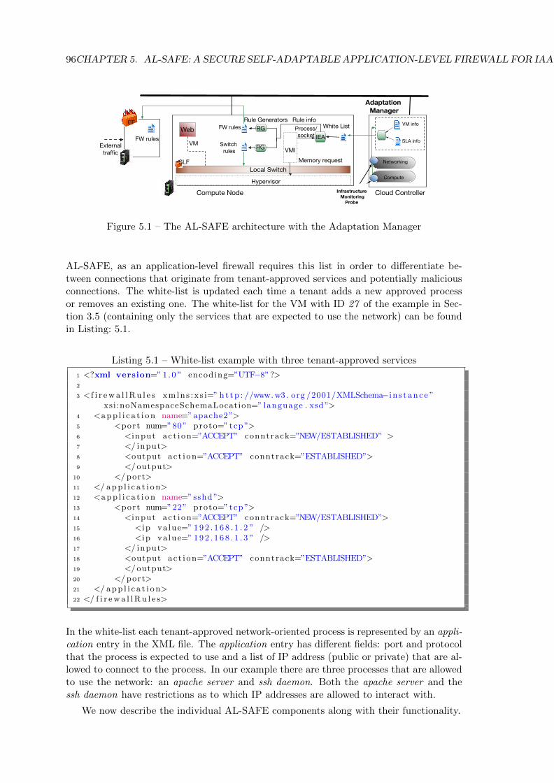
96CHAPTER 5. AL-SAFE: A SECURE SELF-ADAPTABLE APPLICATION-LEVEL FIREWALL FOR IAAS CLOUDS
VMI
Process/socket
White ListRule Generators
FW rulesWeb
Local Switch
VM info
SLA info
Infrastructure Monitoring
Probe
Compute
Networking
Switch rules
FW rules
Hypervisor
Memory request
Rule info
Adaptation Manager
Externaltraffic
Cloud Controller Compute Node
EF
SLF
RG
RGIEA
VM
Figure 5.1 – The AL-SAFE architecture with the Adaptation Manager
AL-SAFE, as an application-level firewall requires this list in order to differentiate be-tween connections that originate from tenant-approved services and potentially maliciousconnections. The white-list is updated each time a tenant adds a new approved processor removes an existing one. The white-list for the VM with ID 27 of the example in Sec-tion 3.5 (containing only the services that are expected to use the network) can be foundin Listing: 5.1.
Listing 5.1 – White-list example with three tenant-approved services
1 <?xml version=” 1 .0 ” encoding=”UTF−8”?>2
3 < f i r ewa l lRu l e s xmlns :x s i=” ht tp : //www.w3 . org /2001/XMLSchema−i n s t ance ”xsi:noNamespaceSchemaLocation=” language . xsd”>
4 <app l i c a t i on name=”apache2”>5 <port num=”80” proto=” tcp ”>6 <input ac t i on=”ACCEPT” conntrack=”NEW/ESTABLISHED” >7 </ input>8 <output ac t i on=”ACCEPT” conntrack=”ESTABLISHED”>9 </output>
10 </ port>11 </ app l i c a t i o n>12 <app l i c a t i on name=” sshd”>13 <port num=”22” proto=” tcp ”>14 <input ac t i on=”ACCEPT” conntrack=”NEW/ESTABLISHED”>15 <ip va lue=” 192 . 1 6 8 . 1 . 2 ” />16 <ip va lue=” 192 . 1 6 8 . 1 . 3 ” />17 </ input>18 <output ac t i on=”ACCEPT” conntrack=”ESTABLISHED”>19 </output>20 </ port>21 </ app l i c a t i o n>22 </ f i r ewa l lRu l e s>
In the white-list each tenant-approved network-oriented process is represented by an appli-cation entry in the XML file. The application entry has different fields: port and protocolthat the process is expected to use and a list of IP address (public or private) that are al-lowed to connect to the process. In our example there are three processes that are allowedto use the network: an apache server and ssh daemon. Both the apache server and thessh daemon have restrictions as to which IP addresses are allowed to interact with.
We now describe the individual AL-SAFE components along with their functionality.

5.3. ADAPTATION PROCESS 97
5.2.2.1 VM Introspection
The VMI component is responsible for introspecting the memory of the monitored guest.VMI is able to coherently access the VM’s physical memory and uses a profile of theVM’s operating system’s kernel to interpret its data structures. Thus VMI first extractsthe list of running processes, and then iterates over this list to check if a network socketfigures in the per-process list of file descriptors. For each network socket found, VMIextracts the process name, the pid as well as source and destination ports, IP address andcommunication protocol. The VMI-created list is named connection list.
5.2.2.2 Information Extraction Agent
The IEA compares the connection list thereafter resulting from the VMI with the tenant-defined white-list of processes. The Adaptation Manager is responsible for sharing thewhite-list with the Information Extraction Agent through a secure channel. The AM is alsoresponsible for sharing updated versions of the white-list (e.g. when a new tenant-approvedservice is added). The IEA assigns an allow tag on connections from the connection listthat figure in the white-list and a block tag on all other connections. The IEA propagatesthe connection information together with an ALLOW or BLOCK instruction to the nextcomponent, the Rule Generators. Furthermore the IEA component keeps a record of therules used for each VM deployed on the compute node on which it runs.
5.2.2.3 Rule Generators
Due to the different types of filtering rules, AL-SAFE features one rule generator pertype of firewall (one for the switch-level firewall and one for the edge firewall). EachRG creates the corresponding rules using all propagated information such as source port,source IP address, destination port, destination IP address and protocol. In the case ofthe switch-level firewall, the rules are grouped by VM with one rule table per VM. Eachset of generated rules is then injected in its respective firewall.
5.2.2.4 Edge Firewall
The Edge firewall is located at the edge of the virtual infrastructure in a separate net-work device and is responsible for external traffic directed towards and from the virtualinfrastructure.
5.2.2.5 Switch-Level Firewall
The Switch-level firewall is responsible for filtering network packets in the local switchusing a list of ALLOW and BLOCK rules.
5.3 Adaptation Process
AL-SAFE automatically adapts the enforced ruleset based on changes in the topologyof the virtual infrastructure and the list of services running in the deployed VMs. Wepresent a high-level overview of the adaptation process in each one of these two cases. Theadaptation steps (from introspection of the AL-SAFE-protected VM until the injection ofthe rules in the two firewalls) are demonstrated in Figure 5.2.
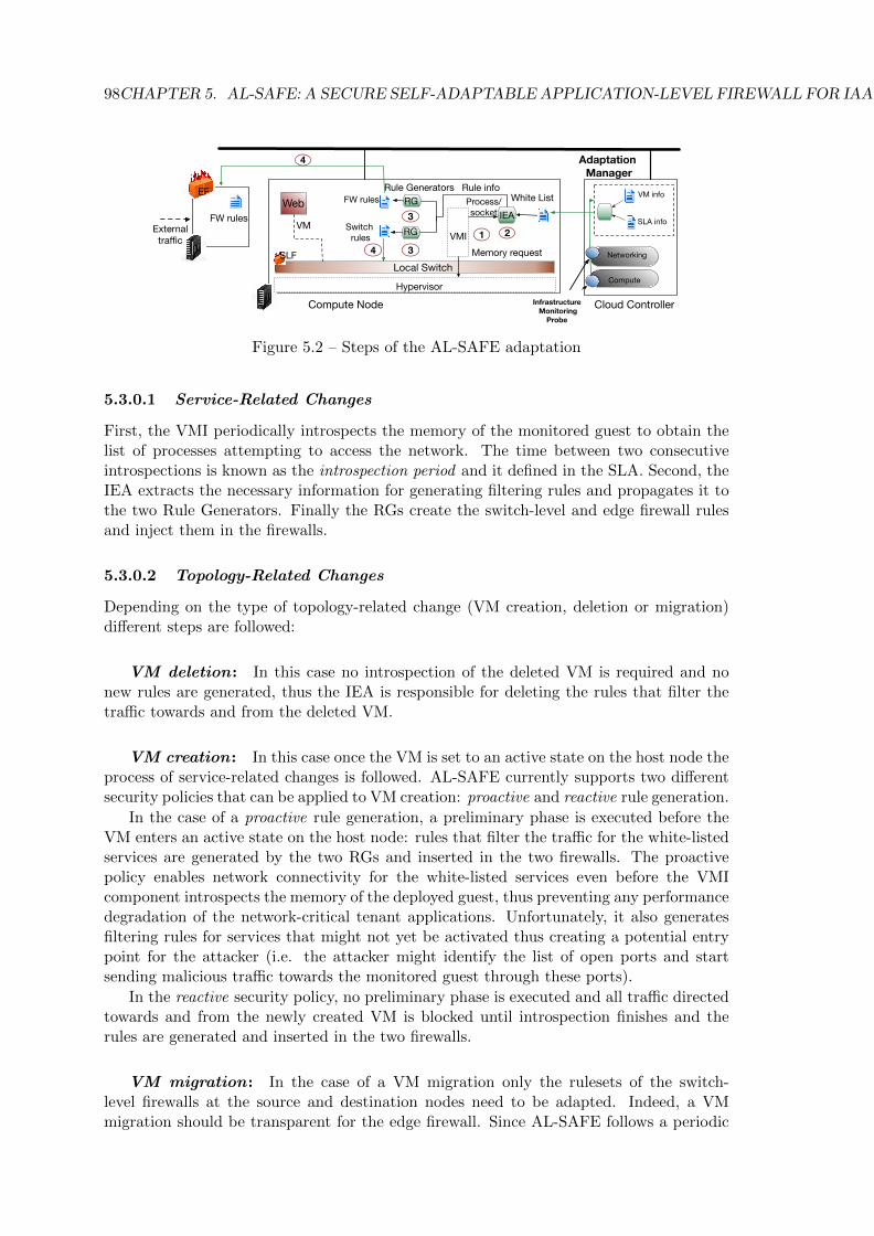
98CHAPTER 5. AL-SAFE: A SECURE SELF-ADAPTABLE APPLICATION-LEVEL FIREWALL FOR IAAS CLOUDS
VMI
Process/socket
White ListRule Generators
FW rulesWeb
Local Switch
VM info
SLA info
Infrastructure Monitoring
Probe
Compute
Networking
Switch rules
FW rules
Hypervisor
Memory request
Rule info
Adaptation Manager
Externaltraffic
Cloud Controller Compute Node
EF
SLF
RG
RGIEA
1 2
3
3
4
4
VM
Figure 5.2 – Steps of the AL-SAFE adaptation
5.3.0.1 Service-Related Changes
First, the VMI periodically introspects the memory of the monitored guest to obtain thelist of processes attempting to access the network. The time between two consecutiveintrospections is known as the introspection period and it defined in the SLA. Second, theIEA extracts the necessary information for generating filtering rules and propagates it tothe two Rule Generators. Finally the RGs create the switch-level and edge firewall rulesand inject them in the firewalls.
5.3.0.2 Topology-Related Changes
Depending on the type of topology-related change (VM creation, deletion or migration)different steps are followed:
VM deletion: In this case no introspection of the deleted VM is required and nonew rules are generated, thus the IEA is responsible for deleting the rules that filter thetraffic towards and from the deleted VM.
VM creation: In this case once the VM is set to an active state on the host node theprocess of service-related changes is followed. AL-SAFE currently supports two differentsecurity policies that can be applied to VM creation: proactive and reactive rule generation.
In the case of a proactive rule generation, a preliminary phase is executed before theVM enters an active state on the host node: rules that filter the traffic for the white-listedservices are generated by the two RGs and inserted in the two firewalls. The proactivepolicy enables network connectivity for the white-listed services even before the VMIcomponent introspects the memory of the deployed guest, thus preventing any performancedegradation of the network-critical tenant applications. Unfortunately, it also generatesfiltering rules for services that might not yet be activated thus creating a potential entrypoint for the attacker (i.e. the attacker might identify the list of open ports and startsending malicious traffic towards the monitored guest through these ports).
In the reactive security policy, no preliminary phase is executed and all traffic directedtowards and from the newly created VM is blocked until introspection finishes and therules are generated and inserted in the two firewalls.
VM migration: In the case of a VM migration only the rulesets of the switch-level firewalls at the source and destination nodes need to be adapted. Indeed, a VMmigration should be transparent for the edge firewall. Since AL-SAFE follows a periodic

5.3. ADAPTATION PROCESS 99
introspection strategy, the arrival of the migration request in an introspection period iscritical. Let us define tx as the introspection period and ty as the time between the laststart of an introspection and the moment when the migration command arrives at thesource node of the deployed VM. Depending on the arrival time of the migration requestwe define two different cases:
1. The migration command arrives between two consecutive introspection actions. Theremaining time until the next introspection (tx − ty) is recorded and is sent as aparameter to the destination node along with the last valid introspection generatedruleset of the source node. The VM is resumed and the next introspection occursafter tx− ty. Since the VM migration command arrived between two introspections,the only way to respect the introspection period (that is not allow more time thantx to pass between to consecutive introspections) is to introspect after tx − ty time.Our strategy is depicted in Figure 5.3.
Introspectionstart
Migration Planned Introspection +1start
Introspectioncompletion
txty
Migrationcomplete
Planned Introspection +1start
tx -ty
Source Host
Destination Host
Figure 5.3 – The migration request arrives between two introspections
2. The migration command arrives during an on-going introspection. In this case thecurrent introspection action is terminated and the result from the last valid intro-spection is sent to the destination node. A new introspection begins as soon as theVM is resumed in the destination node. Since the last introspection was killed it isimportant to obtain a valid introspection result as soon as possible (in order not toimpose any performance penalty in new tenant-approved services that might havestarted right before the last killed introspection), consequently introspection startsimmediately after the VM is resumed. Our strategy is depicted in Figure 5.4.
Introspectionstart
Migration Planned Introspection +1start
Introspectioncompletion
tx
Source Host
Destination Host
Migrationcompletion
Introspection start
Figure 5.4 – The migration request arrives during an introspection
In a migration event the proactive policy is enforced where the last valid ruleset is injectedin the switch-level firewall of the destination node before the VM is resumed.

100CHAPTER 5. AL-SAFE: A SECURE SELF-ADAPTABLE APPLICATION-LEVEL FIREWALL FOR IAAS CLOUDS
5.3.1 Security Threats
We now present the security threats against specific AL-SAFE components and how theycan be exploited from an attacker. We discuss our design choices for securing AL-SAFEfrom these attacks.
5.3.1.1 AL-SAFE Input Sources
AL-SAFE operates based on a tenant-defined white-list of processes that are authorizedto use the network. An attacker could taint the contents of the white-list and allowillegitimate processes to use the network. The API-generated white-list is expressed ina simple XML format for which the parser is easy to make robust. The input file ispre-processed using a AL-SAFE-specific filter that verifies that only AL-SAFE-specificelements and printable ASCII strings without special characters are present in the file.Moreover, no complex interpretation is required since the values of each entry match fieldsof the firewall rules.
5.3.1.2 AL-SAFE Adaptation Arguments
AL-SAFE adapts the enforced rulesets in the two level-firewall based on topology or ser-vice related changes in the virtual infrastructure. Theoretically, an attacker could bypassthe adaptation process or initiate an unnecessary one by tampering with the arguments ofexisting topology-related changes. AL-SAFE relies on the IMPs, which are located insidethe cloud engine, in order to access all VM-related information (i.e. VM id, external/in-ternal IP addresses, tap on the virtual switch, etc). The IMPs are hooks placed inside thecloud engine which copy information from the data structures used by the cloud enginein order to store network-related information regarding the VMs. Since the cloud engineand the information it stores, are considered to be tamper-proof the information extractedfrom the IMPs is considered accurate.
Regarding service-related changes, an attacker could tamper with the adaptation pro-cess in various ways. First, by tainting the arguments of a service (i.e. process name,port, protocol, etc) in order to force AL-SAFE to allow traffic towards and from attacker-preferred ports. AL-SAFE relies on VM introspection in order to detect service-relatedchanges. Introspection parses kernel data structures in the VMs in order to extract the listof active network sockets together with their owner process name. Consequently, the onlyway for an attacker to tamper with the service arguments is by controlling the VM kernelthis is an inherent limitation of all introspection-based solutions and we address it alongwith possible solutions in Sectionreflim. Second, the attacker could force the introspectioncomponent to crash or exploit a software vulnerability in the component itself. The parsingphase relies on commodity tools that may be vulnerable to out-of-bound memory accessesand reference loops in the parsed structures. Out-of-bound accesses are avoided since thecommodity tool that we use (i.e. Volatility, presented later in Section 5.4) is in Pythonwhich features automatic array boundaries check. To protect against reference loops, asa last option a timeout could be used to stop introspecting. The extracted information isonly compared to the white-list of process names or inserted as port numbers (resp. IPaddresses) in the filtering rules. It is thus sufficient to check that extracted values are 16bits integers (resp. valid IP addresses).

5.4. IMPLEMENTATION 101
5.3.1.3 Transfer of Reconfiguration Parameters
In AL-SAFE the tenant-defined white-list is sent from the AM located inside the cloudcontroller to the node hosting the monitored VM. An attacker could perform a ”Man inthe middle” attack during the sending phase and alter the content of the white-list. In ourapproach, we maintain a secure connection open at all times between the cloud controllerand the compute nodes. The authentication protocol used [142] provides authenticationof the AM and guarantees the integrity of the data transferred. Hence, an attacker has noway of intercepting or altering any part of the communication between the cloud controllerand the compute nodes.
5.3.1.4 Firewall Rules
In AL-SAFE network packets are processed by the OpenFlow tables inserted in the localswitch, and by the rules inserted in the edge firewall. Assuming that both filtering enginesare robust, the added rules can be considered safe since the only actions allowed are toallow or drop traffic.
5.4 Implementation
We created a prototype of AL-SAFE from scratch using the KVM [27] hypervisor on aprivate cloud. Our cloud was deployed on OpenStack [32] and we used Open vSwitch(OvS) [137] as a multilayer virtual switch. In this section we present key implementationdetails of each component.
5.4.1 Edge Firewall
For the edge firewall we rely on the Nftables [147] stateful packet filtering framework whichis deployed in a standalone Linux host.
5.4.2 Switch-Level Firewall
For the switch-level firewall our prototype features two versions. The first version usesthe stateless filtering capabilities offered by Open vSwitch (i.e. essentially two rules perservice are required, one for incoming and one for outgoing traffic). In the second version,AL-SAFE supports stateful filtering. The stateful filtering uses the OvS built-in featureof connection tracking conn state in order to generate rules that keep track of open con-nections. Each open connection corresponds to an entry in the conntrack table. Whena packet that is not part of any connection arrives, our prototype creates a new entryin the conntrack table and marks the connection as tracked. Mr Fergal Martin Tricotimplemented the second version of the switch-level firewall during his 3 month Master1internship that I co-supervised. The rules are grouped by VM (that is by switch port),with one OpenFlow table for each VM located on the compute node. The evaluation ofAL-SAFE was conducted using the first version of the prototype.
5.4.3 VMI
In order to introspect the memory of a running VM we used LibVMI [113] combinedwith Volatility Memory Forensics Framework [148]. LibVMI [113] as the evolution ofXenAccess, is a C library with Python bindings that facilitates the monitoring of low-level details (memory, registers, etc) of a running virtual machine. Since KVM does not
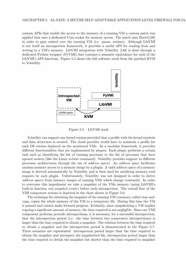
102CHAPTER 5. AL-SAFE: A SECURE SELF-ADAPTABLE APPLICATION-LEVEL FIREWALL FOR IAAS CLOUDS
contain APIs that enable the access to the memory of a running VM a custom patch wasapplied that uses a dedicated Unix socket for memory access. The patch uses libvirt[138]in order to gain control over the running VM (i.e. pause, resume). Although LibVMIis not itself an introspection framework, it provides a useful API for reading from andwriting to a VM’s memory. LibVMI integration with Volatility [148] is done through adedicated Python wrapper (PyVMI) that contains a semantic equivalence for each of theLibVMI’s API functions. Figure 5.5 shows the full software stack from the patched KVMto Volatility.
KVMLibVMI patch
LibVMI
PyVMI
Volatility
IntrospectedVM
Figure 5.5 – LibVMI stack
Volatility can support any kernel version provided that a profile with the kernel symbolsand data structures is created. The cloud provider would have to maintain a profile foreach OS version deployed on the monitored VMs. As a modular framework, it providesdifferent functionalities that are implemented by plugins. Each plugin performs a certaintask such as identifying the list of running processes or the list of processes that haveopened sockets (like the Linux netstat command). Volatility provides support to differentprocessor architectures through the use of address spaces. An address space facilitatesrandom memory access to a memory image by a plugin. A valid address space of a memoryimage is derived automatically by Volatility and is then used for satisfying memory readrequests by each plugin. Unfortunately, Volatility was not designed in order to deriveaddress spaces from memory images of running VMs which change constantly. In orderto overcome this impediment we take a snapshot of the VMs memory (using LibVMI’sbuilt-in function vmi snapshot create) before each introspection. The overall flow of theVMI component actions is depicted in the chart shown in Figure 5.6.
The technique for obtaining the snapshot of the running VM’s memory, called stop-and-copy, copies the whole memory of the VM to a temporary file. During this time the VMis paused and cannot make forward progress. Evidently, since snapshotting a VM impliescopying a significant amount of memory, the time required is not negligible. Since our VMIcomponent performs periodic introspections, it is necessary, for a successful introspection,that the introspection period (i.e. the time between two consecutive introspections) islarger than the time required to obtain a snapshot. The relation between the time requiredto obtain a snapshot and the introspection period is demonstrated in the Figure 5.7.Three scenarios are represented: introspection period larger than the time required toobtain the snapshot and introspect the snapshotted file, introspection period larger thanthe time required to obtain the snapshot but shorter than the time required to snapshot
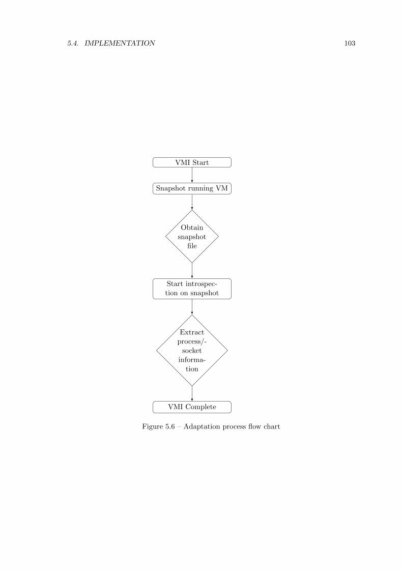
5.4. IMPLEMENTATION 103
VMI Start
Snapshot running VM
Obtainsnapshot
file
Start introspec-tion on snapshot
Extractprocess/-
socketinforma-
tion
VMI Complete
Figure 5.6 – Adaptation process flow chart
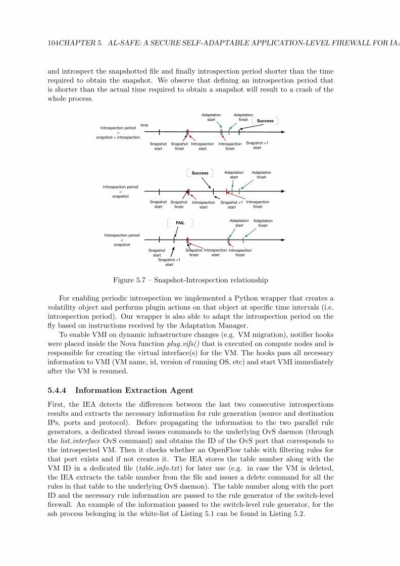
104CHAPTER 5. AL-SAFE: A SECURE SELF-ADAPTABLE APPLICATION-LEVEL FIREWALL FOR IAAS CLOUDS
and introspect the snapshotted file and finally introspection period shorter than the timerequired to obtain the snapshot. We observe that defining an introspection period thatis shorter than the actual time required to obtain a snapshot will result to a crash of thewhole process.
time
Snapshotstart
Introspectionstart
Adaptationstart
Snapshot +1start
Success
Snapshotstart
Introspectionstart
Adaptationstart
Snapshot +1start
Success
Snapshotstart
Introspectionstart
Adaptationstart
Snapshot +1start
FAIL
Snapshotfinish
Introspectionfinish
Adaptationfinish
Snapshotfinish
Introspectionfinish
Adaptationfinish
Adaptationfinish
Introspectionfinish
Snapshotfinish
Introspection period>
snapshot + introspection
Introspection period>
snapshot
Introspection period<
snapshot
Figure 5.7 – Snapshot-Introspection relationship
For enabling periodic introspection we implemented a Python wrapper that creates avolatility object and performs plugin actions on that object at specific time intervals (i.e.introspection period). Our wrapper is also able to adapt the introspection period on thefly based on instructions received by the Adaptation Manager.
To enable VMI on dynamic infrastructure changes (e.g. VM migration), notifier hookswere placed inside the Nova function plug vifs() that is executed on compute nodes and isresponsible for creating the virtual interface(s) for the VM. The hooks pass all necessaryinformation to VMI (VM name, id, version of running OS, etc) and start VMI immediatelyafter the VM is resumed.
5.4.4 Information Extraction Agent
First, the IEA detects the differences between the last two consecutive introspectionsresults and extracts the necessary information for rule generation (source and destinationIPs, ports and protocol). Before propagating the information to the two parallel rulegenerators, a dedicated thread issues commands to the underlying OvS daemon (throughthe list interface OvS command) and obtains the ID of the OvS port that corresponds tothe introspected VM. Then it checks whether an OpenFlow table with filtering rules forthat port exists and if not creates it. The IEA stores the table number along with theVM ID in a dedicated file (table info.txt) for later use (e.g. in case the VM is deleted,the IEA extracts the table number from the file and issues a delete command for all therules in that table to the underlying OvS daemon). The table number along with the portID and the necessary rule information are passed to the rule generator of the switch-levelfirewall. An example of the information passed to the switch-level rule generator, for thessh process belonging in the white-list of Listing 5.1 can be found in Listing 5.2.
5.5. EVALUATION METHODOLOGY 105
Listing 5.2 – Information passed at the switch-level firewall
1 Rul e i n f o ( t ab l e = 28 , ovs por t = 4 , proto = TCP, port = 22 , i p s =[ 1 9 2 . 1 6 8 . 1 . 2 , 1 9 2 . 1 6 8 . 1 . 3 ] , a c t i on = ALLOW)
In this example, the IEA has cross-checked the introspection result with the white-list(found in Listing 5.1) and has found that the ssh process on port 22 is allowed to use thenetwork. Then, it acquires the OvS port number (4) for that particular VM (through thelist interface OvS command ) and the number for the OpenFlow table (28) where all therules for that particular VM should be stored (stored in table info.txt). Consequently hepropagates the necessary information to the SLF rule generator.
5.4.5 Rule Generators
We implemented a separate rule generator for each firewall. The edge firewall rule gener-ator produces Nftables-compatible rules while the switch-level firewall generator producesOvS compatible rules. To minimize the adaptation time, both rule generators are executedin parallel.
5.5 Evaluation Methodology
In this section we present our evaluation of AL-SAFE. We first present the objectivesof our evaluation plan followed by our experimentation methodology. We performed theevaluation on the first version of our prototype, where the switch-level firewall is stateless(i.e. two rules per service are required one for incoming and one for outgoing traffic).The evaluation concludes with the correctness analysis and limitations of AL-SAFE inSection 5.6.3.
5.5.1 Objectives of the Evaluation
The main goal of AL-SAFE is to guarantee an equilibrium of a three-dimensional trade-offbetween performance, security and cost. In a cloud infrastructure different stakeholdersare involved (i.e. tenants and the provider), consequently the trade-offs should be exploredfrom each stakeholder’s perspective. We first discuss our approach for evaluating AL-SAFE’s performance, followed by the security and cost aspects.
5.5.1.1 Performance
The aspect of performance refers to the time required for AL-SAFE to complete a fulladaptation loop (i.e. from the moment a dynamic event occurs until both firewalls aresuccessfully reconfigured). In order to get an estimation of the overall time (i.e. latency)we need to answer the following questions:
1. What is the overall time (in seconds) needed until both firewalls are successfully re-configured? The adaptation process consists of four phases: sharing of the white-list,snapshotting-introspection, rule generation and rule insertion. The overall latencyis the sum of each phase’s individual latency, which naturally leads us to a secondquestion:
2. What is the time (in seconds) required to complete each phase? Depending on thetasks performed by each phase there are different components involved. Different

106CHAPTER 5. AL-SAFE: A SECURE SELF-ADAPTABLE APPLICATION-LEVEL FIREWALL FOR IAAS CLOUDS
factors, related to each component’s functionality, affect it’s individual completiontime. Consequently, a third question arises:
3. What factors affect the execution time of each component? We discuss the factorsper component:
• Adaptation Manager: It is responsible for sharing the tenant-generatedwhite-list with nodes that host the monitored VMs. The number of entriesin the list impacts the size of the file thus the time required for sending it tothe corresponding nodes.
• Rule Generators: They are responsible for generating the two separate rulecategories and inserting them in the firewalls. The overall execution time forthese components depends on the number of generated rules and the time re-quired to insert them. Respectively, the number of generated rules is related tothe number and type of services running inside a monitored VM and the tenant-defined white-list. Regarding the rule insertion time, for the switch level-firewallthe number of rules affects the insertion time, while for the edge firewall therules are written to a file, the file is then sent to the firewall host and finallythe rules are inserted.
• Introspection: The VMI component performs two functionalities: snapshot-ting and introspecting. Since the technique employed for snapshotting the mon-itored VM is stop-and-copy the only factor that affects the snapshotting time isthe size of the monitored VM’s memory. Introspection time depends on differentfactors as follows:
– Number of running processes,
– Number of created sockets,
– Size of the introspected file (snapshot).
5.5.1.2 Security and Correctness
From a tenant’s perspective, AL-SAFE is an application-level introspection-based firewall.AL-SAFE needs to allow only tenant-authorized services to use the network while blockingall other malicious network activity, even when the monitored VM is compromised. Fromthe provider’s perspective, AL-SAFE needs to guarantee that no security vulnerabilitiesare added in the provider’s infrastructure by deploying AL-SAFE.
5.5.1.3 Cost
Cost minimization is one of AL-SAFE’s core objectives. Thus, the associated overheadsboth from a tenant’s and the provider’s perspectives need to be examined. For theprovider-associated cost we calculate the performance overhead imposed by AL-SAFEin normal cloud operations (e.g. VM migration) and the system resources consumed byAL-SAFE’s components. Respectively, for tenant-associated cost we calculate the perfor-mance overhead imposed by AL-SAFE on tenant applications running inside monitoredVMs.
• Provider-associated cost: What is the latency (in seconds) introduced by AL-SAFE to a normal cloud operation such as VM migration? and What is the cost ofdeploying AL-SAFE’s components in a compute node in terms of CPU and RAM?All of the resources consumed by AL-SAFE are resources that cannot be assigned to
5.5. EVALUATION METHODOLOGY 107
virtual machines (hence cannot generate profit for the provider). Consequently anexact computation for the CPU percentage and memory consumption is required.
• Tenant-associated cost: What is the cost of deploying AL-SAFE as perceivedby tenant applications? In order to identify the quantitative cost induced by AL-SAFE we examine two different kinds of applications: process-intensive and network-intensive. We select these application profiles for simultaneously examining themain factors affecting each AL-SAFE component under different workloads. For theprocess-intensive application we identify the associated cost as the additional timerequired to perform a specific task. For the network-intensive application we identifythe cost as the overhead induced in network throughput, application throughput andlatency in connection establishment.
5.5.2 Experimentation Methodology
We now present the detailed scenarios that we used in order to perform the actual evalua-tion. It is worth mentioning that the scenarios were designed in order to address multipleevaluation objectives simultaneously. We select a Linux kernel build as a process intensiveapplication and a web server and Iperf as network intensive applications. For a typicalcloud operation we select a VM migration as a super case that includes VM creation (inthe destination node) and VM deletion (in the source node). Each application is testedunder different workload and introspection period parameters.
5.5.2.1 VM Migration
The VM migration scenario focuses on the provider-associated cost of deploying AL-SAFE.We aim at providing the reader with a fine-grained view of how intrusive a full adaptationloop is to VM migration. Although it can also provide an accurate estimation of thetime (latency in seconds) required to perform each phase in the adaptation this is notthe focus of this experiment. We compute the overall migration time of a monitored VMin seconds. The scenario has two options: no workload running in the migrated VM(idle) and a memory intensive workload running in the migrated VM. In the first casemigration time is minimum (hence adaptation penalty is maximised) while in the secondcase the migration time is significantly larger (hence adaptation penalty is minimal). Inthis scenario the adaptation process only affects the switch-level firewall.
5.5.2.2 Linux kernel Build
In the Linux Kernel bulid scenario we compile a Linux kernel inside the untrusted VM andwe vary the introspection period. The scenario serves a dual purpose as it addresses boththe performance and cost objectives of our evaluation plan. Depending on the objectivewe compute different metrics:
1. Performance of AL-SAFE: We record the time required for each of AL-SAFEcomponents to complete its functionality. The component that dominates the over-all latency of a full self-adaptation loop in this particular scenario should be theintrospection component. Since the scenario features a process-intensive applicationwith no network activity, no rules are generated or inserted in the two firewalls. Asdiscussed in Section 5.5.1.1, due to the snapshot technique selected, the memorysize is the only parameter that influences the time required to obtain the snapshot.

108CHAPTER 5. AL-SAFE: A SECURE SELF-ADAPTABLE APPLICATION-LEVEL FIREWALL FOR IAAS CLOUDS
Regarding the introspection time and with respect to the application profile we iden-tify the number of processes and the size of the introspected file (i.e. snapshot) asinfluencing factors.
2. Tenant-associated cost: We measure the elapsed build time in seconds. Whetherparallel compilation is enabled or not and the number of virtual CPUs in the virtualmachine are expected to influence the result (due to the change in the number ofprocesses). We also consider the time between two consecutive introspections tobe an influencing parameter for the overall build time. Each introspection requiresa snapshot of the monitored VM which freezes the VM during the snapshot time(due to the stop-and-copy technique), consequently the overhead increases with theintrospection frequency.
5.5.2.3 Apache Web Server
In this scenario we install a web server on the monitored VM for serving new client requests.The scenario serves a dual purpose with regards to the evaluation objectives:
1. it quantitatively estimates AL-SAFE’s performance
2. it calculates tenant and provider associated cost of deploying AL-SAFE
Depending on the evaluation objective we compute different metrics:
1. Performance of AL-SAFE: We record the time required for each AL-SAFE com-ponent to complete its functionality. We investigate the individual latency of eachcomponent: Introspection (VMI), Information Extraction Agent (IEA), rule gen-erators (RGs) and rule insertion. As discussed in Section 5.5.1.1 the factors thataffect the introspection time are: (a) size of the introspected file (i.e. snapshot),(b) number of processes and (c) number of sockets. Two of the factors (process andsocket numbers) can be indirectly influenced through variation of the requests/sec-ond workload parameter (i.e. more requests/second imply more open sockets). Thesize of the introspected file can be influenced through assigning different memoryvalues to the monitored VM. Regarding rule creation and insertion we recall that forthe edge firewall a secure connection is required in order to inject the rules. Con-sequently, the influencing factors are the number of rules and the time required toestablish a secure connection. In this case a variation in the number of requests canalso indirectly influence the rule creation and insertion times. An example would bea scenario where the requests come from different client IP addresses and a list-basedtenant security policy (detailed explanation below) is applied.
2. Tenant-associated cost: for calculating the tenant-associated cost of deployingAL-SAFE we compute the mean of the following values: latency induced in the re-sponse time for each new connection and service throughput. For the new connectionresponse time different setups are examined depending on: the location of the client,the security policy enforced and the time of the request’s arrival with respect to theintrospection period. We detail each one:
• Location of the client :
(a) The client is located in a virtual machine belonging to the same tenant:only the switch-level firewall needs to be reconfigured.

5.5. EVALUATION METHODOLOGY 109
(b) The client is located outside the cloud infrastructure: both the edge firewalland the switch-level firewall need to be reconfigured.
(c) The client is located inside the cloud infrastructure but in a virtual ma-chine that belongs to a different tenant. In our setup the edge firewall islocated on the gateway connecting the cloud infrastructure with the outsideworld. When a client request from a VM belonging to tenant T1 is issuedto tenant’s T2 web server VM (public ip: 80) it first reaches the Neutroncontroller and then is redirected to the host executing the web server (es-sentially the request never leaves the cloud). Similarly to the first type ofrequest, only the switch level firewall needs to be reconfigured.
• Tenant-defined security policy :
(a) Policy allow all : Allow every request on port 80. This policy requires onlyone rule in each firewall thus the number of requests does not induce anyadditional latency.
(b) Policy allow only white-listed IPs: In this case only requests from a tenant-defined address list are allowed.The latency depends on the number of IPsin the list. Since our switch-level firewall is stateless, we generate two rulesper IP one for incoming and one for outgoing traffic while for the edge-firewall (stateful) only one is enough (since the conntracking feature allowsto use a general rule for established connections).
(c) Policy block black-listed IPs: Reasoning is similar to the allow only white-listed IPs policy. Every request is allowed besides the ones originating fromblacklisted IPs. Again the latency depends on the length of the list. Thispolicy can be combined with the allow all policy (i.e. allow connectionsfrom all IPs except the blacklisted ones).
• Arrival of the request time in the introspection cycle: Depending on when theconnection request arrives and what is the timeout period for the TCP connec-tion, we foresee the following outcomes:
(a) The request arrives before the introspection has been completed. Thatis: arrival of request + timeout < introspection complete. In this case theconnection fails.
(b) The request arrives after the introspection has finished but before theadaptation of the two firewalls has been completed. That is: introspec-tion complete< arrival of request + timeout< adaptation complete. Againthe connection fails.
(c) The request arrives before the adaptation of the two firewalls has beencompleted but the timeout is enough for the connection to wait untilthe completion of the adaptation. That is: introspection complete < ar-rival of request + timeout ≥ adaptation complete and arrival of request +timeout > adaptation complete. In this case the connection succeeds(theport will be open).
(d) The request arrives after the adaptation of the two firewalls has been com-pleted. In this case the connection succeeds.
After defining the metrics used in this scenario we now focus on the varying parame-ter in the different workloads that we use, that is the number of requests per second.The web server spawns new sockets in order to serve the requests. In this case weexpect an increment in the introspection time. Regarding memory size, we test with

110CHAPTER 5. AL-SAFE: A SECURE SELF-ADAPTABLE APPLICATION-LEVEL FIREWALL FOR IAAS CLOUDS
2048MB memory for the VM and two virtual CPUs. The memory size representsaverage workload use-cases (medium traffic websites, small databases, etc) as statedin [15]. The memory size is expected to be the only factor affecting the snapshottingtime.
3. Provider-associated cost: we calculate AL-SAFE resource utilization in terms ofCPU percentage and memory consumption.
This scenario refers to measuring the performance impact of a full adaptation loop for aserver that is accepting incoming connections. For evaluating the impact of a full adapta-tion on a client located inside the virtual infrastructure (in an AL-SAFE-protected VM)attempting to connect to a web server located outside the virtual infrastructure (henceadaptation of both firewalls is required in order to allow the client traffic to pass unim-peded), we calculate the latency induced in the response time for each new connection.In this case we execute a full adaptation loop only on the client’s side. Unfortunately, incontrast to the server side where the connection port is known a priori (port 80 or port443 for https requests), the client case comes with one impediment: the port number isunknown until the client attempts to make a new connection (hence a rule that allowsthe connection cannot be inserted proactively in the two firewalls rulesets). In order toovercome this impediment we include two security policies:
1. Proactive security policy: allow all traffic directed towards the server’s IP andport 80. With this option all traffic towards the web server is allowed regardless ofthe source port.
2. Reactive security policy: wait until introspection detects the source port of thewhite-listed process and then insert the rule that allows traffic for that particularport only.
The proactive option clearly favors performance as it offers minimal service disturbancebut it also introduces security vulnerabilities (since no control is performed on the sourceprocess of the connection) as a potentially malicious process executing on the monitoredclient can gain access to the legitimate web server.
5.5.2.4 Iperf
This scenario is used to evaluate the effect of the introspection phase on the networkthroughput. We install Iperf [149] in the VM which acts as a server and we use a separatenode outside the cloud infrastructure as a client. Iperf measures the maximum availablebandwidth on an IP network. The selected scenario focuses on the cost objective of ourevaluation plan. The computed metrics are:
1. Tenant-associated cost: we measure the network throughput in sending/receivinga TCP stream. As in the kernel compilation scenario, each time the VM is intro-spected a snapshot is taken, which freezes the VM during the snapshot time (due tothe stop-and-copy technique), consequently the overhead increases with introspectionfrequency.
2. Provider-associated cost: we calculate AL-SAFE resource utilization in terms ofCPU percentage and memory consumption.
We compare the Iperf results with and without introspection.

5.5. EVALUATION METHODOLOGY 111
5.5.2.5 Microbenchmarks
In the previous scenarios we described our methodology for measuring the overhead ofa full adaptation loop on network- and process-intensive tenant applications. This sec-tion focuses on a fine-grained view of the cost for a full adaptation loop particularly onindividual connection establishment.
5.5.2.5.1 TCP connection establishment time: We wrote a client/server TCPprogram and measure the TCP connection setup time for a single connection to a nodeoutside the virtual infrastructure. We address both cases where either the server or theclient are executed inside the monitored VM. We compare the results obtained withoutadaptation to the ones with the adaptation of the two firewalls.
• Server inside the AL-SAFE-protected VM: The setup of this case is depicted inFigure 5.8.
TCPserverport:80
VMI
Process/socket
White ListRule Generators
FW rules
Local Switch
Switch rules
FW rules
Hypervisor
Rule info
Compute Node
EF
RG
RGIEA
Client
Outside Node
1
VM id: 25
port_id:4
IP: 172.10.24.203
OF_table:16
Figure 5.8 – TCP server setup
In this case a client located outside the cloud infrastructure is trying to connect toa tcp server on port 80 running inside an AL-SAFE-protected VM. The VM withID:25 has port id:4 and OF table:16 on the virtual switch of the compute node. Thewhite-list of this scenario is shown in Listing 5.3. The white-list states that theprocess named tcp server is allowed to accept incoming connections.
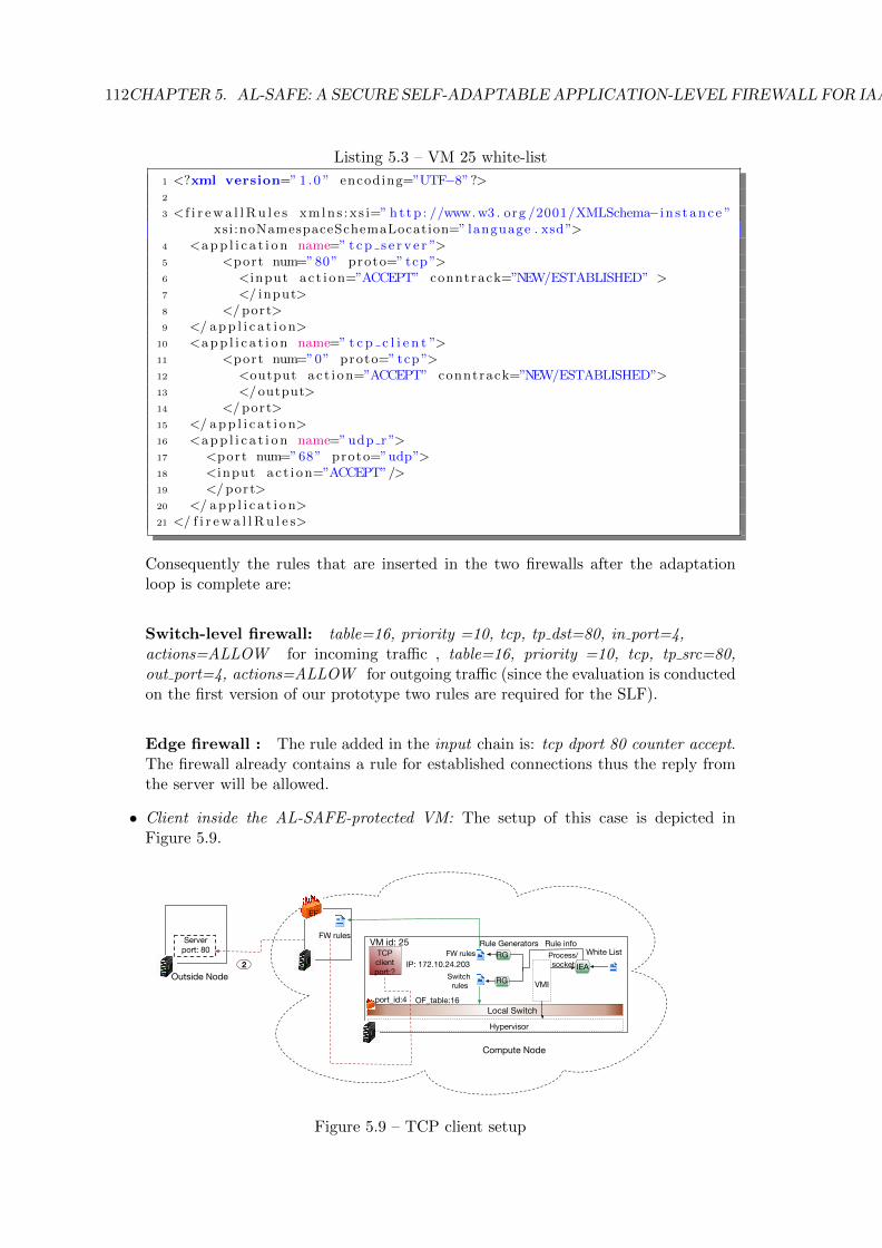
112CHAPTER 5. AL-SAFE: A SECURE SELF-ADAPTABLE APPLICATION-LEVEL FIREWALL FOR IAAS CLOUDS
Listing 5.3 – VM 25 white-list
1 <?xml version=” 1 .0 ” encoding=”UTF−8”?>2
3 < f i r ewa l lRu l e s xmlns :x s i=” ht tp : //www.w3 . org /2001/XMLSchema−i n s t ance ”xsi:noNamespaceSchemaLocation=” language . xsd”>
4 <app l i c a t i on name=” t cp s e r v e r ”>5 <port num=”80” proto=” tcp ”>6 <input ac t i on=”ACCEPT” conntrack=”NEW/ESTABLISHED” >7 </ input>8 </ port>9 </ app l i c a t i o n>
10 <app l i c a t i on name=” t c p c l i e n t ”>11 <port num=”0” proto=” tcp ”>12 <output ac t i on=”ACCEPT” conntrack=”NEW/ESTABLISHED”>13 </output>14 </ port>15 </ app l i c a t i o n>16 <app l i c a t i on name=”udp r ”>17 <port num=”68” proto=”udp”>18 <input ac t i on=”ACCEPT”/>19 </ port>20 </ app l i c a t i o n>21 </ f i r ewa l lRu l e s>
Consequently the rules that are inserted in the two firewalls after the adaptationloop is complete are:
Switch-level firewall: table=16, priority =10, tcp, tp dst=80, in port=4,actions=ALLOW for incoming traffic , table=16, priority =10, tcp, tp src=80,out port=4, actions=ALLOW for outgoing traffic (since the evaluation is conductedon the first version of our prototype two rules are required for the SLF).
Edge firewall : The rule added in the input chain is: tcp dport 80 counter accept.The firewall already contains a rule for established connections thus the reply fromthe server will be allowed.
• Client inside the AL-SAFE-protected VM: The setup of this case is depicted inFigure 5.9.
TCPclientport:?
VMI
Process/socket
White ListRule Generators
FW rules
Local Switch
Switch rules
FW rules
Hypervisor
Rule info
Compute Node
EF
RG
RGIEA
Server port: 80
Outside Node
port_id:4
2 IP: 172.10.24.203
OF_table:16
VM id: 25
Figure 5.9 – TCP client setup
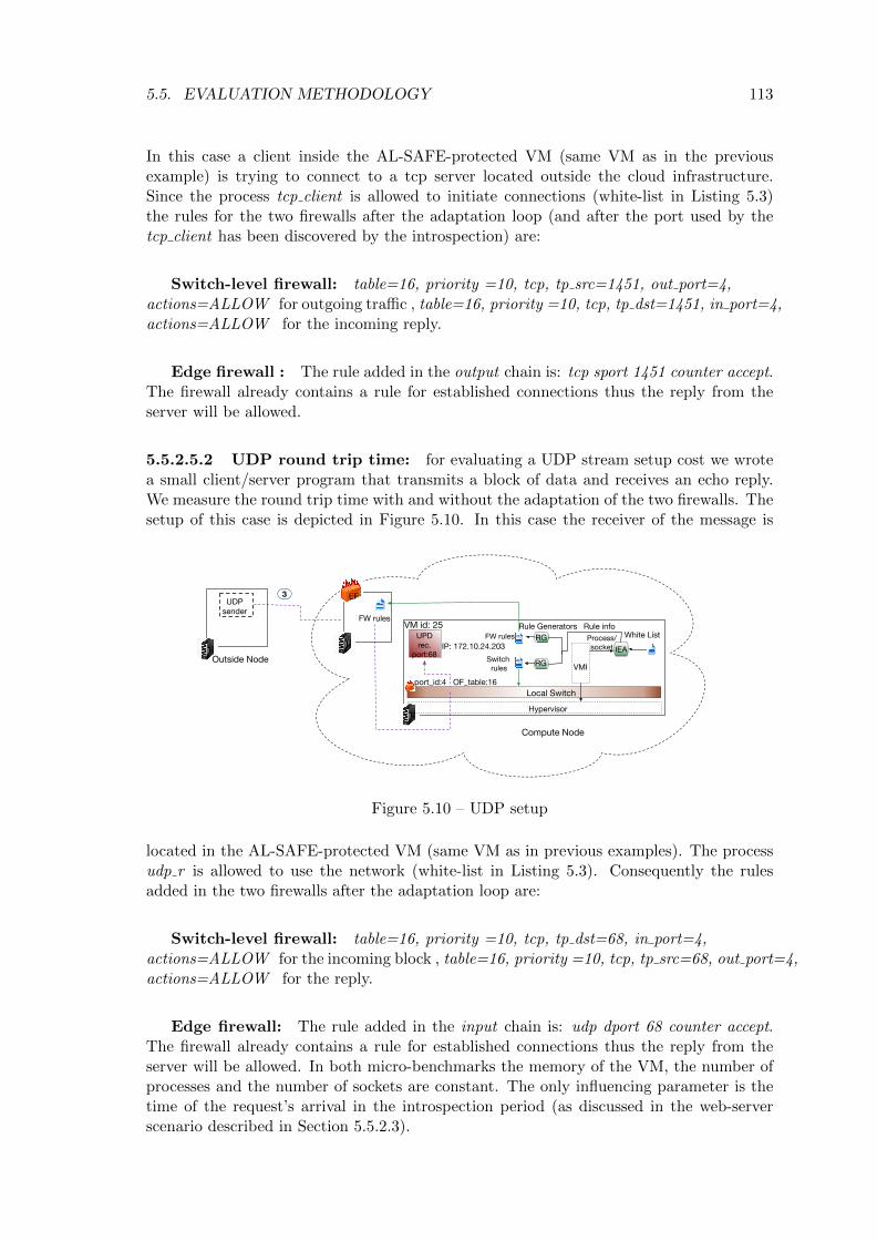
5.5. EVALUATION METHODOLOGY 113
In this case a client inside the AL-SAFE-protected VM (same VM as in the previousexample) is trying to connect to a tcp server located outside the cloud infrastructure.Since the process tcp client is allowed to initiate connections (white-list in Listing 5.3)the rules for the two firewalls after the adaptation loop (and after the port used by thetcp client has been discovered by the introspection) are:
Switch-level firewall: table=16, priority =10, tcp, tp src=1451, out port=4,actions=ALLOW for outgoing traffic , table=16, priority =10, tcp, tp dst=1451, in port=4,actions=ALLOW for the incoming reply.
Edge firewall : The rule added in the output chain is: tcp sport 1451 counter accept.The firewall already contains a rule for established connections thus the reply from theserver will be allowed.
5.5.2.5.2 UDP round trip time: for evaluating a UDP stream setup cost we wrotea small client/server program that transmits a block of data and receives an echo reply.We measure the round trip time with and without the adaptation of the two firewalls. Thesetup of this case is depicted in Figure 5.10. In this case the receiver of the message is
UPDrec.
port:68 VMI
Process/socket
White ListRule Generators
FW rules
Local Switch
Switch rules
FW rules
Hypervisor
Rule info
Compute Node
EF
RG
RGIEA
UDPsender
Outside Node
3
VM id: 25
port_id:4
IP: 172.10.24.203
OF_table:16
Figure 5.10 – UDP setup
located in the AL-SAFE-protected VM (same VM as in previous examples). The processudp r is allowed to use the network (white-list in Listing 5.3). Consequently the rulesadded in the two firewalls after the adaptation loop are:
Switch-level firewall: table=16, priority =10, tcp, tp dst=68, in port=4,actions=ALLOW for the incoming block , table=16, priority =10, tcp, tp src=68, out port=4,actions=ALLOW for the reply.
Edge firewall: The rule added in the input chain is: udp dport 68 counter accept.The firewall already contains a rule for established connections thus the reply from theserver will be allowed. In both micro-benchmarks the memory of the VM, the number ofprocesses and the number of sockets are constant. The only influencing parameter is thetime of the request’s arrival in the introspection period (as discussed in the web-serverscenario described in Section 5.5.2.3).

114CHAPTER 5. AL-SAFE: A SECURE SELF-ADAPTABLE APPLICATION-LEVEL FIREWALL FOR IAAS CLOUDS
5.6 Evaluation Results
After describing our evaluation scenarios and the underlying rationale, we present theresults obtained from the different experiments. Section 5.6.1 presents the results fromthe performance evaluation of AL-SAFE while Section 5.6.2 discusses correctness aspectsof our approach. Finally AL-SAFE limitations are detailed in Section 5.6.3.
5.6.1 Performance and Cost Analysis
To do our experiments we deployed a datacenter with three physical hosts: one cloudcontroller and two compute nodes. Each physical host has 48GB RAM and runs a 64bitLinux Ubuntu 14.04 distribution. The machines are interconnected with a 1Gb/s network.All the VMs deployed on the compute nodes run a 64bit Linux Ubuntu 13.10 distributionwith 2 cores and 2GB RAM. We also deployed the Nftables firewall in a fourth physicalhost with the same hardware as our cloud nodes. All reported results are compared to abaseline value obtained without AL-SAFE.
Before running our experiments we conducted a preliminary set of tests to calculatethe time for a full snapshot of a 2GB VM’s memory. We calculated the mean snapshottime to 1.5 seconds over 10 repetitions (standard deviation 0.05). Since the technique usedcopies the whole memory of the VM into a dedicated file the size of the VM is the onlyfactor affecting the snapshot time.
5.6.1.1 VM Migration
To generate the memory-intensive workload we used bw mem wr from the LMBench bench-mark [143] suite with a 1024MB working set. The working set is allocated, zeroed andthen written as a series of 4 byte integers. In this scenario we aim at proving that the timerequired to reconfigure the switch-level firewall is independent from the VM workload. Weexecuted 10 repetitions of each case. The results are presented in Figure 5.11. In the
idle
bw_mem_wr
VM workload
0
5
10
15
20
25
30
Mig
rati
on t
ime (
s)
6.05
21.58
11.02
26.53 Without AL-SAFEWith AL-SAFE
Figure 5.11 – Migration time with and without adaptation
figure, the migration time with and without AL-SAFE for both cases (idle and memoryintensive workload) is depicted. The imposed overhead in the migration operation is thesame in both cases (4.95s), which validates our hypothesis that the cost of adapting thefirewall ruleset is independent from the VM workload. A per-phase breakdown is shown inFigure 5.12. We insert two rules per service in the switch-level firewall (one for ingress andone for egress traffic) and only one rule in the edge firewall. The relatively high amount of

5.6. EVALUATION RESULTS 115
Introspectionstart
Migrationrequest arrived
Next Introspection
VM resumed
Source Host
Destination Host
Adaptation Manager:Stop introspection,
transfer last valid result
MigrationStart
RuleGeneration
RuleInsertion
3.84s
0.02s0.01s
Figure 5.12 – Breakdown of each phase in seconds
time (3.84 seconds) required for the Adaptation Manager to notify the Introspection agentof the source node, in order to interrupt the introspection and send the last valid results,is mostly due to a defect in the DNS configuration resulting in a slow SSH connectionestablishment.
5.6.1.2 Linux Kernel
We compiled a Linux kernel inside the VM and we varied the introspection period. Thekernel was compiled with a configuration including only the modules loaded by the runningkernel of the VM, using gcc 4.8.4 with a degree of parallelism of 3. We used the timecommand line utility for measuring the overall execution time. The VM is not expectedto start services that use the network during the execution time of the experiment thusno adaptation of the firewalls is required.
Before presenting the results, we discuss a model that estimates the minimum overheadvalue on the kernel compilation time. Let us define: x the time overhead introduced inthe kernel compilation time, α as the mean value of the time required to take a snapshotand n the number of introspections performed during the experiment. Since in eachintrospection a snapshot of the AL-SAFE-protected VM is taken, a temporary freeze ofthe VM is performed. Consequently, the minimum overhead should be the result of thenumber of introspections times the snapshot time. That is min(x) = n× α.
The mean value over five repetitions is shown in Figure 5.13. The results clearly
60 120 300 no introIntrospection period (seconds)
0
50
100
150
200
Overh
ead in K
ern
el co
mpila
tion t
ime (
seco
nds)
(184.2)
(62.4)
(14.4)
Figure 5.13 – Impact of the introspection period on kernel compilation time
demonstrate a dependency between the period of introspections and execution time. The
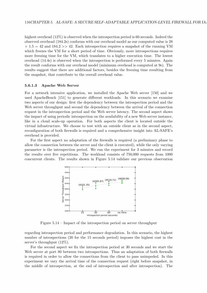
116CHAPTER 5. AL-SAFE: A SECURE SELF-ADAPTABLE APPLICATION-LEVEL FIREWALL FOR IAAS CLOUDS
highest overhead (12%) is observed when the introspection period is 60 seconds. Indeed theobserved overhead (184.2s) conforms with our overhead model as our computed value is 28× 1.5 = 42 and 184.2 >> 42. Each introspection requires a snapshot of the running VMwhich freezes the VM for a short period of time. Obviously, more introspections requiresmore freezing time for the VM, which translates to a higher execution time. The lowestoverhead (14.4s) is observed when the introspection is performed every 5 minutes. Againthe result conforms with our overhead model (minimum overhead is computed at 9s). Theresults suggest that there are additional factors, besides the freezing time resulting fromthe snapshot, that contribute to the overall overhead value.
5.6.1.3 Apache Web Server
For a network intensive application, we installed the Apache Web server [150] and weused ApacheBench [151] to generate different workloads. In this scenario we examinetwo aspects of our design: first the dependency between the introspection period and theWeb server throughput and second the dependency between the arrival of the connectionrequest in the introspection period and the Web server latency. The second aspect showsthe impact of using periodic introspection on the availability of a new Web server instance,like in a cloud scale-up operation. For both aspects the client is located outside thevirtual infrastructure. We choose to test with an outside client as in the second aspect,reconfiguration of both firewalls is required and a comprehensive insight into AL-SAFE’soverhead is provided.
For the first aspect no adaptation of the firewalls is required (a preliminary phase toallow the connection between the server and the client is executed), while the only varyingparameter is the introspection period. We run the experiment for 3 minutes and recordthe results over five repetitions. The workload consists of 750,000 requests from 1000concurrent clients. The results shown in Figure 5.14 validate our previous observation
15 30 60 no introIntrospection period (seconds)
2000
2500
3000
3500
4000
4500
5000
5500
6000
Serv
er
Thro
ughput
(Req/s
)
(4101.35)
(4305.87) (4519.71) (4658.09)
Figure 5.14 – Impact of the introspection period on server throughput
regarding introspection period and performance degradation. In this scenario, the highestnumber of introspections (20 for the 15 seconds period) imposes the highest cost in theserver’s throughput (12%).
For the second aspect we fix the introspection period at 30 seconds and we start theWeb server at port 80 between two introspections. Thus an adaptation of both firewallsis required in order to allow the connections from the client to pass unimpeded. In thisexperiment we vary the arrival time of the connection request (right before snapshot, inthe middle of introspection, at the end of introspection and after introspection). The
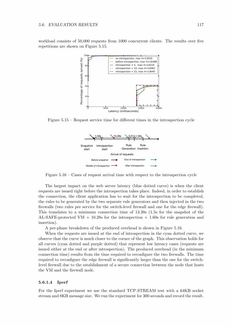
5.6. EVALUATION RESULTS 117
workload consists of 50,000 requests from 1000 concurrent clients. The results over fiverepetitions are shown on Figure 5.15.
0 5000 10000 15000 20000
Latency (milliseconds)
0
20
40
60
80
100
Perc
enta
ge o
f re
quest
s se
rved (
%) no introspection, max rt=13520
before introspection, max rt=16388introspection + 5, max rt=14219introspection + 10, max rt=14082introspection + 15, max rt=13640
Figure 5.15 – Request service time for different times in the introspection cycle
Introspectionstart
Arrival of requests
Rule Generation
Rule Insertion
10.28s 0.01s 1.59s
Middle of introspection
End of introspection
After introspection
Before snapshot
1.50s
Snapshotstart
Figure 5.16 – Cases of request arrival time with respect to the introspection cycle
The largest impact on the web server latency (blue dotted curve) is when the clientrequests are issued right before the introspection takes place. Indeed, in order to establishthe connection, the client application has to wait for the introspection to be completed,the rules to be generated by the two separate rule generators and then injected in the twofirewalls (two rules per service for the switch-level firewall and one for the edge firewall).This translates to a minimum connection time of 13.38s (1.5s for the snapshot of theAL-SAFE-protected VM + 10.28s for the introspection + 1.60s for rule generation andinsertion).
A per-phase breakdown of the produced overhead is shown in Figure 5.16.
When the requests are issued at the end of introspection in the cyan dotted curve, weobserve that the curve is much closer to the corner of the graph. This observation holds forall curves (cyan dotted and purple dotted) that represent low latency cases (requests areissued either at the end or after introspection). The produced overhead (in the minimumconnection time) results from the time required to reconfigure the two firewalls. The timerequired to reconfigure the edge firewall is significantly larger than the one for the switch-level firewall due to the establishment of a secure connection between the node that hoststhe VM and the firewall node.
5.6.1.4 Iperf
For the Iperf experiment we use the standard TCP STREAM test with a 64KB socketstream and 8KB message size. We run the experiment for 300 seconds and record the result.
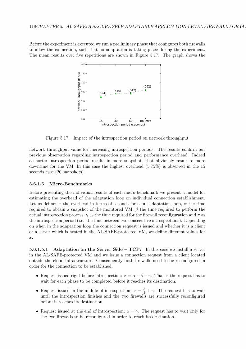
118CHAPTER 5. AL-SAFE: A SECURE SELF-ADAPTABLE APPLICATION-LEVEL FIREWALL FOR IAAS CLOUDS
Before the experiment is executed we run a preliminary phase that configures both firewallsto allow the connection, such that no adaptation is taking place during the experiment.The mean results over five repetitions are shown in Figure 5.17. The graph shows the
15 30 60 no introIntrospection period (seconds)
500
550
600
650
700
750
800
Netw
ork
Thro
ughput
(Mb/s
)
(624)(640) (642)
(662)
Figure 5.17 – Impact of the introspection period on network throughput
network throughput value for increasing introspection periods. The results confirm ourprevious observation regarding introspection period and performance overhead. Indeeda shorter introspection period results in more snapshots that obviously result to moredowntime for the VM. In this case the highest overhead (5.75%) is observed in the 15seconds case (20 snapshots).
5.6.1.5 Micro-Benchmarks
Before presenting the individual results of each micro-benchmark we present a model forestimating the overhead of the adaptation loop on individual connection establishment.Let us define: x the overhead in terms of seconds for a full adaptation loop, α the timerequired to obtain a snapshot of the monitored VM, β the time required to perform theactual introspection process, γ as the time required for the firewall reconfiguration and π asthe introspection period (i.e. the time between two consecutive introspections). Dependingon when in the adaptation loop the connection request is issued and whether it is a clientor a server which is hosted in the AL-SAFE-protected VM, we define different values forx.
5.6.1.5.1 Adaptation on the Server Side – TCP: In this case we install a serverin the AL-SAFE-protected VM and we issue a connection request from a client locatedoutside the cloud infrastructure. Consequently both firewalls need to be reconfigured inorder for the connection to be established.
• Request issued right before introspection: x = α+ β + γ. That is the request has towait for each phase to be completed before it reaches its destination.
• Request issued in the middle of introspection: x = β2 + γ. The request has to wait
until the introspection finishes and the two firewalls are successfully reconfiguredbefore it reaches its destination.
• Request issued at the end of introspection: x = γ. The request has to wait only forthe two firewalls to be reconfigured in order to reach its destination.
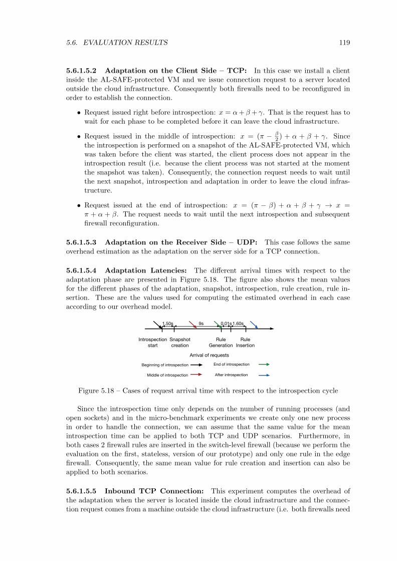
5.6. EVALUATION RESULTS 119
5.6.1.5.2 Adaptation on the Client Side – TCP: In this case we install a clientinside the AL-SAFE-protected VM and we issue connection request to a server locatedoutside the cloud infrastructure. Consequently both firewalls need to be reconfigured inorder to establish the connection.
• Request issued right before introspection: x = α+ β + γ. That is the request has towait for each phase to be completed before it can leave the cloud infrastructure.
• Request issued in the middle of introspection: x = (π − β2 ) + α + β + γ. Since
the introspection is performed on a snapshot of the AL-SAFE-protected VM, whichwas taken before the client was started, the client process does not appear in theintrospection result (i.e. because the client process was not started at the momentthe snapshot was taken). Consequently, the connection request needs to wait untilthe next snapshot, introspection and adaptation in order to leave the cloud infras-tructure.
• Request issued at the end of introspection: x = (π − β) + α + β + γ → x =π + α + β. The request needs to wait until the next introspection and subsequentfirewall reconfiguration.
5.6.1.5.3 Adaptation on the Receiver Side – UDP: This case follows the sameoverhead estimation as the adaptation on the server side for a TCP connection.
5.6.1.5.4 Adaptation Latencies: The different arrival times with respect to theadaptation phase are presented in Figure 5.18. The figure also shows the mean valuesfor the different phases of the adaptation, snapshot, introspection, rule creation, rule in-sertion. These are the values used for computing the estimated overhead in each caseaccording to our overhead model.
Introspectionstart
Arrival of requests
Rule Generation
Rule Insertion
9s 0.01s 1.60s
Middle of introspection
End of introspection
After introspection
Beginning of introspection
1.50s
Snapshotcreation
Figure 5.18 – Cases of request arrival time with respect to the introspection cycle
Since the introspection time only depends on the number of running processes (andopen sockets) and in the micro-benchmark experiments we create only one new processin order to handle the connection, we can assume that the same value for the meanintrospection time can be applied to both TCP and UDP scenarios. Furthermore, inboth cases 2 firewall rules are inserted in the switch-level firewall (because we perform theevaluation on the first, stateless, version of our prototype) and only one rule in the edgefirewall. Consequently, the same mean value for rule creation and insertion can also beapplied to both scenarios.
5.6.1.5.5 Inbound TCP Connection: This experiment computes the overhead ofthe adaptation when the server is located inside the cloud infrastructure and the connec-tion request comes from a machine outside the cloud infrastructure (i.e. both firewalls need

120CHAPTER 5. AL-SAFE: A SECURE SELF-ADAPTABLE APPLICATION-LEVEL FIREWALL FOR IAAS CLOUDS
baselinebefore intro
middle of introend of intro
after intro
Arrival of the request in the introspection cycle
0
5
10
15
20
25
30
Overh
ead in T
CP c
onnect
ion t
ime (
s)
0.0
11.89
3.881.57
0.0
Figure 5.19 – Inbound TCP connection establishment time
to be reconfigured). Figure 5.19 shows the connection establishment times when the con-nection requests are issued at different times during the introspection process(beginning,middle, end, after). The case with the smallest overhead (1.57s) is when the request isissued at the end of introspection. Indeed the request only has to wait for the firewall re-configuration in order to reach the server. According to our model, the observed overheadshould be 1.61s which is indeed the case. We observe again a relatively high time requiredfor the secure connection establishment (1.60s), which is due to the already discussed DNSdefect when establishing a secure SSH connection.
The case that demonstrates the highest overhead is the one when the request is issuedright before the snapshot. That is because, the request has to wait until the snapshot istaken, the introspection is complete and the rules are generated and injected in the twofirewalls. According to our model the estimated overhead in this case is : α + β + γ =1.5s+ 9.0s + 1.61s = 12.11s. The observed overhead is 11.89s. The 0.22s (1.68%) deviationbetween the estimated overhead value and the observed overhead is attributed to the factthat the estimated overhead was computed based on mean values for each phase.
The results demonstrate that the arrival of requests in the introspection cycle plays amajor role in the connection establishment time. For a client attempting to connect toan AL-SAFE-protected server the best case scenario is issuing a request at the end of theintrospection cycle.
5.6.1.5.6 Outbound TCP Connection: In this experiment the TCP client is in-stalled in the AL-SAFE-protected VM inside the cloud infrastructure issuing connectionrequests to a server located outside the cloud infrastructure. Consequently, both firewallsneed to be reconfigured in order for the client request to pass unimpeded. In contrast withan inbound TCP connection where the connection port is known a priori (e.g. port 80), anoutbound TCP connection faces the limitation of an unknown port number. The overheadin connection establishment times, when issuing the request at different times during theintrospection process, is shown in Figure 5.20. Initiating a request right before introspec-tion is now the best case scenario with the smallest overhead. Indeed the open socket willbe included in the new introspection result (since the client process is not started in theAL-SAFE-protected VM when the snapshot of the first introspection was taken detailedpresentation in Section 5.6.1.5). According to our model the estimated overhead is: α +β + γ = 1.5s + 9s + 1.6s = 12.11s. The observed overhead is : 12.03s which validatesour initial hypothesis about the cost of issuing the request right before the introspectionof the AL-SAFE-protected VM. In all other cases the time period between the time ofthe request and the next introspection has to be added to the connection establishment

5.6. EVALUATION RESULTS 121
baselinebefore intro
middle of introend of intro
after intro
Arrival of the request in the introspection cycle
0
5
10
15
20
25
30
Overh
ead in T
CP c
onnect
ion e
stablis
ment
tim
e (
s)
0.0
12.03
23.15
18.12
0.0
Figure 5.20 – Outbound TCP connection establishment time
time. For example, in the case where the request is issued at the middle of introspectionthe added time is 10.5s (the introspection period was defined at π = 15s and the requestwas issued at the middle of the introspection process at β
2 = 4.5s consequently the waiting
time amounts at 10.5s). In this case the estimated overhead should be: π− β2 + α + β +
γ = 10.5s + 1.5s + 9s + 1.61s = 22.61s. The actual overhead is 23.15s (we again observea deviation of 0.54s or 2.37% between estimated and observed overhead due to the meanvalues used for calculating the estimated overhead).
The case of a client located inside the AL-SAFE-protected VM is the exact oppositeof the server case (presented in Section 5.6.1.5.5). The best case scenario now is when theconnection request is issued at the beginning of the introspection.
5.6.1.5.7 UDP Round Trip Time: In the UDP round trip time experiment weinstall the process receiving the ECHO request inside a monitored VM located insidethe cloud infrastructure. Consequently, both firewalls need to be reconfigured in orderfor the message to complete its roundtrip. Figure 5.21 shows the overhead in connectionestablishment times when the message is send at different times in the introspection period.The observed overhead follows a similar pattern with the one imposed on the inbound
baselinebefore intro
middle of introend of intro
after intro
Arrival of the request in the introspection cycle
0
5
10
15
20
25
30
Overh
ead in U
DP r
ound t
rip t
ime (
s)
0.0
12.63
7.03
2.080.0
Figure 5.21 – Inbound UDP round trip time
TCP connections (see Section 5.6.1.5.5). The best case scenario is when the message issent at the end of the introspection process (i.e. it has to wait only for rule creationan reconfiguration). Indeed the observed overhead conforms with our estimation: 2.08sand 1.61s respectively the deviation is once more attributed to the mean values used for
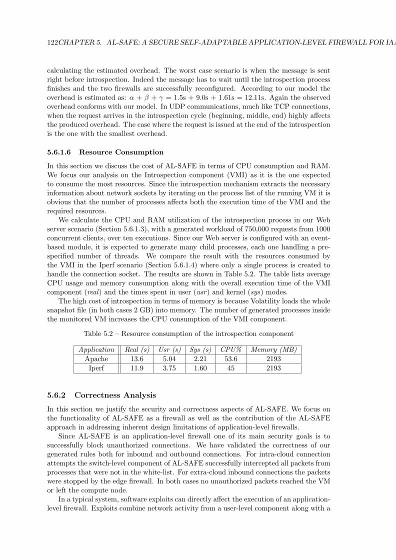
122CHAPTER 5. AL-SAFE: A SECURE SELF-ADAPTABLE APPLICATION-LEVEL FIREWALL FOR IAAS CLOUDS
calculating the estimated overhead. The worst case scenario is when the message is sentright before introspection. Indeed the message has to wait until the introspection processfinishes and the two firewalls are successfully reconfigured. According to our model theoverhead is estimated as: α + β + γ = 1.5s + 9.0s + 1.61s = 12.11s. Again the observedoverhead conforms with our model. In UDP communications, much like TCP connections,when the request arrives in the introspection cycle (beginning, middle, end) highly affectsthe produced overhead. The case where the request is issued at the end of the introspectionis the one with the smallest overhead.
5.6.1.6 Resource Consumption
In this section we discuss the cost of AL-SAFE in terms of CPU consumption and RAM.We focus our analysis on the Introspection component (VMI) as it is the one expectedto consume the most resources. Since the introspection mechanism extracts the necessaryinformation about network sockets by iterating on the process list of the running VM it isobvious that the number of processes affects both the execution time of the VMI and therequired resources.
We calculate the CPU and RAM utilization of the introspection process in our Webserver scenario (Section 5.6.1.3), with a generated workload of 750,000 requests from 1000concurrent clients, over ten executions. Since our Web server is configured with an event-based module, it is expected to generate many child processes, each one handling a pre-specified number of threads. We compare the result with the resources consumed bythe VMI in the Iperf scenario (Section 5.6.1.4) where only a single process is created tohandle the connection socket. The results are shown in Table 5.2. The table lists averageCPU usage and memory consumption along with the overall execution time of the VMIcomponent (real) and the times spent in user (usr) and kernel (sys) modes.
The high cost of introspection in terms of memory is because Volatility loads the wholesnapshot file (in both cases 2 GB) into memory. The number of generated processes insidethe monitored VM increases the CPU consumption of the VMI component.
Table 5.2 – Resource consumption of the introspection component
Application Real (s) Usr (s) Sys (s) CPU% Memory (MB)
Apache 13.6 5.04 2.21 53.6 2193
Iperf 11.9 3.75 1.60 45 2193
5.6.2 Correctness Analysis
In this section we justify the security and correctness aspects of AL-SAFE. We focus onthe functionality of AL-SAFE as a firewall as well as the contribution of the AL-SAFEapproach in addressing inherent design limitations of application-level firewalls.
Since AL-SAFE is an application-level firewall one of its main security goals is tosuccessfully block unauthorized connections. We have validated the correctness of ourgenerated rules both for inbound and outbound connections. For intra-cloud connectionattempts the switch-level component of AL-SAFE successfully intercepted all packets fromprocesses that were not in the white-list. For extra-cloud inbound connections the packetswere stopped by the edge firewall. In both cases no unauthorized packets reached the VMor left the compute node.
In a typical system, software exploits can directly affect the execution of an application-level firewall. Exploits combine network activity from a user-level component along with a

5.6. EVALUATION RESULTS 123
kernel-level module that hides the user-level component from the view of the application-level firewall. The malicious exploit likely obtains full-system privileges and can thus haltthe execution of the firewall. The malicious kernel-level module can alter the hooks usedby the in-kernel module of the application-level firewall so that the firewall is simply neverinvoked as data passes through the network. Conventional application-level firewalls failunder these types of attacks. AL-SAFE withstands attacks from these types of exploits.However, AL-SAFE can still retrieve a maliciously crafted connection list and allow con-nections for malicious applications that impersonate legitimate white-listed applications.Compared to a traditional application-level firewall which operates inside the host and ifcompromised can open any port regardless if it is in the white-list or not, AL-SAFE doesnot open any not white-listed port.
AL-SAFE denies all unknown connections by default. In a production system whereservices have sufficiently long life-times, this tackles the case of an attacker timing theintrospection period and attempting to use the network between two consecutive intro-spections. The performance overhead of this choice on each connection is outlined inSection 5.6.1.5.
Finally we analyze the potential vulnerabilities added by AL-SAFE to the providerinfrastructure. AL-SAFE’s components are exposed to three kinds of potentially maliciousinput. First, the white-list of processes, second the added rules and third the introspectionresults. The design choices for the three items (as presented in Section 5.3.1) address theissue of malicious input.
We now discuss AL-SAFE’s limitations and our suggested approach for handling them.
5.6.3 Limitations
AL-SAFE as an application-level firewall located outside the monitored VM, is able toprovide, through virtual machine introspection, the same degree of visibility as an insidethe host solution. However, AL-SAFE suffers from some limitations. We detail theselimitations based on their category:
• Performance: AL-SAFE performs introspection periodically, which delays the net-work connectivity of newly started services and clients. To reduce this overhead,AL-SAFE could introspect on watchpoints, e.g. on listen() and connect() syscallson TCP sockets.
• Security: As all introspection-based security solutions AL-SAFE is vulnerable tokernel data structure manipulation. An attacker who fully controls the VM canalso tamper with kernel data structures to control introspection results. To countersuch attacks we could use approaches to check the VM’s kernel integrity [109]. Fur-thermore, an additional security impediment would be a previous legitimate processthat has turned malicious. An attacker can hijack a connection after it has beenestablished and verified by AL-SAFE as legitimate. It can use a software exploit totake control of a particular process bound to the port or use a kernel module to alterpackets before they are sent out to the local switch network interface. To counterthis issue we could place dedicated Intrusion Detection Systems in the infrastructure,using the approach of SAIDS.

124CHAPTER 5. AL-SAFE: A SECURE SELF-ADAPTABLE APPLICATION-LEVEL FIREWALL FOR IAAS CLOUDS
5.7 Summary
In this chapter we presented AL-SAFE, the second instantiation of our security monitoringframework which focuses on firewalls. AL-SAFE is a secure application-level introspection-based firewall that is able to adapt the enforced ruleset based on changes in the virtualinfrastructure topology and the list of services running in the monitored VMs. AL-SAFE’sdesign addresses the inherent design limitation of application level-firewalls that run insidethe monitored VMs. Hence, they can be compromised by malicious kernel-level code thatis executed inside the monitored host. Using virtual machine introspection AL-SAFEpulls the firewall outside the untrusted VM while maintaining an inside-the-VM visibility.AL-SAFE filters traffic at two distinct points in the virtual infrastructure regulating theload imposed on other security devices, which are part of our framework such as intrusiondetection systems.
We have conducted a thorough evaluation of our approach examining both performanceand correctness aspects. We have shown that the overhead in cloud operations such asVM migration is independent from the VM workload. This overhead is lower than themigration time. Our results show a dependency between the introspection period and thegenerated overhead for tenant applications running inside the untrusted VM. Increasing theintrospection period depending on the type of activity inside the VM (fewer introspectionsfor compute-intensive applications that do not use the network) could significantly decreasethe overhead. Our prototype already features a dedicated mechanism for adapting theintrospection period on the fly.
Finally, we have shown that AL-SAFE correctly blocks unauthorized connections whileallowing all tenant-approved connections to pass unimpeded. The design choices made forAL-SAFE’s components do not add any security vulnerabilities in the provider’s infras-tructure. AL-SAFE’s limitations both from a security (kernel data structure manipula-tion) and performance aspects (delay of network connectivity) were presented along withsuggestions on how they can be addressed.
Chapter 6
Conclusion
This chapter summarizes our contributions and details how these contributions fulfil theobjectives presented in Section 1.3. The contributions along with their assessment arelisted in Section 6.1 while suggestions for future research work are presented in Section 6.2.
6.1 Contributions
In this thesis we designed a self-adaptable security monitoring framework that is ableto adapt its components based on dynamic events that occur in a cloud infrastructure.Four main objectives were defined: self-adaptation, tenant-driven customization, securityand cost minimization. Our framework achieves these objectives and constitutes a flexiblemonitoring solution for virtualized infrastructures that is able to integrate different types ofmonitoring devices. Two different instantiations of our framework, SAIDS and AL-SAFEwere presented in detail.
SAIDS, a self-adaptable network intrusion detection system uses Local Intrusion Detec-tion Sensors (LIDS) in order to monitor traffic towards and from the cloud infrastructure.SAIDS reaction to different types of dynamic events was presented and justified in order toprovide the reader with a clear overview of the adaptation process. The first instantiationof our framework is a scalable solution that can alter the existing configuration and thecomputational resources available to a set of LIDSs depending on the load of monitoredtraffic while maintaining an adequate level of detection. SAIDS prototype was developedusing different cloud technologies (e.g. OpenStack [32], Open vSwitch [137]). Our evalua-tion under different scenarios that resemble production environments allowed us to assessSAIDS performance, scalability, and correctness. Our results showed that SAIDS is ableto handle 5000 LIDS (evaluation performed on 8 core machines with 24GB of RAM each– our testbed’s machines memory capacity imposed a limitation on the number of LIDSsthat our prototype can handle in parallel) while imposing negligible overhead to cloudoperations.
AL-SAFE is the second instantiation of our security monitoring framework which fo-cuses on an active monitoring component, the firewall. AL-SAFE is executed outside themonitored VMs and filters traffic at distinct points of the virtual infrastructure combin-ing an edge firewall, located at the interface between the cloud network and the externalnetwork, with a switch-level firewall. We proved that our design is able to address theinherent design limitation of application-level firewalls (malicious code exposure due toinside-the-host execution) and at the same time maintain an inside-the-host level of vis-ibility through virtual machine introspection. The adaptation of AL-SAFE’s enforcedruleset for different types of dynamic events was thoroughly detailed, followed by a jus-
125
126 CHAPTER 6. CONCLUSION
tification of subsequent actions. Finally, our evaluation presented a comprehensive studyof the trade-offs between the security, adaptation benefits of deploying AL-SAFEand theperformance overhead imposed on cloud operations and tenant applications hosted in thevirtual infrastructure. Our results have shown that the overhead imposed by AL-SAFEon new sockets of network-oriented tenant applications highly depends on the arrival timeof the connection request in the introspection period.
We now discuss how our work addresses the four objectives that were defined in theintroduction of this thesis.
Self-adaptation: Our framework is able to adapt its components based on three typesof dynamic events that occur in a cloud infrastructure: topology-related, service-relatedand monitoring load-related events. Our framework’s core component, the AdaptationManager, is able to make adaptation decisions based on the type of event and act as acoordinator of the adaptation process synchronizing the different components involved.The AM as a high-level component guarantees that the adaptation decision remains ab-stracted from the type of the monitoring device, providing our framework with anotherlevel of genericness. Both SAIDS and AL-SAFE adapt their enforced rulesets upon receiv-ing the adaptation arguments from the AM. In order to guarantee the accurate translationof the adaptation arguments to device-specific configuration parameters both SAIDS andAL-SAFE feature dedicated components that interact with the actual monitoring devices.In both SAIDS and AL-SAFE prototypes we integrate different off-the-self components (2NIDSs and 2 firewalls) with no modifications in their code.
Tenant-driven customization: Our framework takes into account tenant-definedmonitoring requirements as they are expressed through a dedicated API. These require-ments may refer to monitoring tailored for specific services that are deployed in the virtualinfrastructure or to performance-related metrics. The Adaptation Manager guaranteesthat the tenant requests will be taken into account in the adaptation decision and will bepropagated to lower level agents, the Master Adaptation Drivers (MADs), that will trans-late them to device-specific configuration parameters. Our framework supports dedicatedactions in case a tenant-defined requirement is violated (e.g. altering the computationalresources available to a monitoring device in case a performance-related metric exceeds atenant-defined threshold).
Security: Our framework is able to guarantee that the adaptation process will not addany security flaw in the monitoring device itself or in the provider’s infrastructure. Ourdesign choices have proven that the different elements that participate in the adaptation ofa monitoring device (i.e adaptation sources, input files, etc) do not add any new securityflaws and do not create any potential entry point for the attacker. Furthermore, in bothof our frameworks instantiations we have experimentally validated the correctness of theadaptation result. The monitoring devices continue to remain operational during theadaptation process, guaranteeing that an adequate level of detection is maintained.
Cost minimization: Our framework is able to guarantee that the cost for both ten-ants and the provider in terms of application performance and computational resources iskept at a minimal level. SAIDS evaluation results showed that our framework’s instanti-ation imposes negligible overhead in normal cloud operations. Regarding computationalresources (CPU and RAM) deploying SAIDS bears minimal cost. As a passive monitor-ing solution, SAIDS does not directly affect the performance of network-oriented cloudapplications. AL-SAFE’s overhead in normal cloud operations does not depend on theVM workload while the CPU and memory cost is tolerable. AL-SAFE follows a time-based introspection model and as such the overhead for new sockets of network-oriented

6.2. FUTURE WORK 127
tenant applications highly depends on the arrival time of the connection request in theintrospection period.
The work presented in this thesis was able to address the gap in existing cloud securitymonitoring frameworks regarding reaction to dynamic events. Existing solutions onlypartially address the defined objectives (as described in Section 1.3) while our framework isable to combine self-adaptation based on dynamic events with accurate security monitoringresults.
This thesis presented the design of a self-adaptable security monitoring framework thatis able to adapt its components based on different types of dynamic events that occur in acloud infrastructure. SAIDS and AL-SAFE the framework’s two instantiations, addressedself-adaptation for two different types of security devices, intrusion detection systems andfirewalls. Naturally, the work done in this thesis can be extended. We have identifiedseveral directions of improvement that would lead to a complete self-contained monitoringinfrastructure. We discuss these directions in the next section.
6.2 Future Work
Our future work is organized in three categories depending on feasibility and time requiredto complete the described improvements. In Section 6.2.1 we present a few short termgoals that constitute performance and design improvements of our existing instantiations.Section 6.2.2 focuses on other components of our framework while Section 6.2.3 concludesthis chapter with our vision regarding a self-contained security monitoring framework.
6.2.1 Short-Term Goals
Different design and performance improvements regarding SAIDS and AL-SAFE proto-types could be realised.
SAIDS: Currently SAIDS does not feature a mechanism for automatic discovery ofnew services that are deployed in the monitored VMs. The only way for SAIDS to becomeaware of a change in the list of running services (and subsequently reconfigure the involvedLIDSs) is through our framework’s dedicated API needing the tenant to declare that aservice was started or stopped. A solution for automatic service discovery would be forSAIDS to use AL-SAFE’s periodic introspection results. Each time a new legitimateservice is detected in a VM by introspection, the Adaptation Manager could trigger anadaptation of the enforced ruleset of the LIDS responsible for monitoring the traffic thatflows towards and from that particular VM. The addition of automatic service discoverydoes not require a significant change in the existing SAIDS design since the AdaptationManager is currently shared between the two instantiations.
AL-SAFE: As demonstrated by the performance evaluation of AL-SAFE, periodicintrospection imposes unnecessary overhead to applications that are not network-intensive(see the kernel-build results). A solution would be to correlate the type of application activ-ity with the introspection period for example computation-intensive applications can havea larger introspection period than network-intensive applications. Furthermore, instead ofa periodic introspection period AL-SAFE could adopt a watchpoint-based introspectionmodel in which the VMI component could introspect every time a specific event occurs (e.g.a listen syscall on a TCP socket). Finally, our results have shown that the response timeof the introspection component is not negligible. In order to improve the response time ofthis component and subsequently decrease the overhead imposed by the adaptation loopon new connections, introspection could be optimized by introspecting directly on LibVMI

128 CHAPTER 6. CONCLUSION
rather than a combination of LibVMI and Volatility. This change implies implementing aversion of the netstat command using the VM’s memory pages exported by LibVMI andnecessary information regarding kernel data structures. Introspecting directly on LibVMIholds an additional advantage, the removal of the snapshotting phase, that was necessaryfor providing a coherent address space to volatility. This improvement will significantlyreduce the memory consumption of the VMI component.
Dependency Database: Currently all the necessary information for the monitoringdevices involved in the monitoring of a particular VM is contained in simple text files.Although in Chapter 3 we defined that this information should be stored in the Depen-dency Database we did not have time to implement this component. Including a relationaldatabase (e.g. MySQL [152]) for storing this information in the existing framework im-plementation should require minimal changes to the the Adaptation Manager component.These changes are necessary in order to facilitate connection with the database as well asexchange of information for the latter a message protocol could be used like for exampleRabbitMQ [153].
Tenant API: Currently, the tenant API as defined in Chapter 3 has not yet beenimplemented. A simple Restful interface can be used in order to provide the transla-tion between high-level tenant monitoring requirements and Adaptation Manager-readableadaptation arguments.
6.2.2 Mid-Term Goals
This section focuses on expansion of our framework to other types of security devices aswell as addressing aspects like multitenancy and combining security monitoring for tenantsand the provider.
Other types of security devices: In order to extend the monitoring capabilitiesof our framework to other types of monitoring (e.g. inside-the-host activity monitoring,network flow analysis) other types of monitoring devices need to be included. Currently,our self-adaptable security monitoring framework includes only network-based intrusiondetection systems and firewalls. A possible improvement would be to include host-basedIDSs or network analyzers like Bro [154]. Since we plan to include other types of IDSs thechanges required would primarily refer to SAIDS. Many host-based IDSs operate based onagents that are installed locally inside the monitored VM and perform different types ofmonitoring (e.g file integrity checking, rootkit detection, etc). These agents communicatewith a central manager and periodically report findings. In order to support this model,the design changes required for SAIDS are two fold. First, at the level of the MasterAdaptation Driver. Instead of being responsible for regenerating the actual configurationfile for the IDS (like in the LIDS case) the MAD could simply forward relevant monitoringparameters to the appropriate Adaptation Worker (AW). Depending on the number ofagents reporting to each AW the MAD could also adapt the portion of computationalresources available to each AW in order to perform load balancing. Second, at the levelof the Adaptation Worker, instead of having one AW per detection process, a single AWinstance could be responsible for all detection agents running inside a group of VMs (e.g.all the VMs residing in the same compute node). Since most detection agents supportremote configuration through a secure connection, the AW could be located in a separatedomain, introducing another security layer between a potentially compromised detectionagent and the SAIDS component.
Other types of security devices that could be included are log collectors and aggrega-tors. In order to satisfy the cost minimization objective, a log collector instance would be
6.2. FUTURE WORK 129
responsible for gathering and unifying the logs produced by a subset of monitoring devices(e.g. all the devices that monitor VMs that reside on the same compute node). Regardingthe tenant-driven customization objective, the collector would apply special filters to thecollected logs (e.g. if a specific attack for which tenants have requested additional monitor-ing has been detected or if the number of attacks in a specific time window has exceededa certain threshold) and propagate the results to an aggregator instance. Tenants couldaccess the aggregated logs through a dedicated mechanism that guarantees authenticationand data integrity, satisfying the correctness objective. Different policies, designed to copewith the scale of the system and adapt the number of collectors and aggregators, could bedefined in order to address the self-adaptation objective.
Multi-tenancy: The current version of our security monitoring framework does notaddress implications that arise in multi-tenant environments. In order to enable securitymonitoring for different tenants, we need to consider the sharing of the monitoring de-vices between tenants. Component sharing between tenants can also be perceived as anadditional aspect of cost minimization. We now discuss the necessary changes in our twoinstantiations SAIDS and AL-SAFE in order to enable component sharing.
Since each tenant has its own network, and legacy network intrusion detection systemsdo not support monitoring two different networks with the same NIDS instance, SAIDS willhave to assign separate LIDSs to different tenants. However, the remaining components(Adaptation Manager and Master Adaptation Driver) can still be shared between tenants.In order to differentiate between LIDS that belong to different tenants, an extra fieldindicating the ID of the tenant that this device is assigned to can be added in the setof information stored for each LIDS probe. Each MAD could maintain a per-tenant listwith all the LIDS names that are under its control. Our evaluation results have shownthat both the MAD and the AM can handle multiple adaptation requests in parallel, thusenabling parallel adaptation of LIDS that belong to different tenants.
For AL-SAFE device sharing implies using the same firewall (either switch-level oredge) for filtering traffic towards and from VMs that belong to different tenants. Sincethe filtering is performed by dedicated rules, installing rules for different VMs in the samefirewall device is straightforward. In order to address simultaneous dynamic events thatconcern different tenants, parallel generation of filtering rules that concern different VMsis necessary. Unfortunately, in the current version of AL-SAFE parallel rule generationis only supported for VMs that reside in different compute nodes. For enabling parallelgeneration of rules for VMs that reside in the same compute node, parallel introspection ofthose VMs is needed. Unfortunately, in the current implementation the VMI componentdoes not support parallel introspection of collocated VMs (because it is single-threaded).Consequently, the core change for AL-SAFE supporting multi-tenancy requires makingVMI multithreaded. A multi-threaded VMI component that introspects directly on Lib-VMI will also impose a significantly lower memory overhead.
Combining the security monitoring of tenants and the provider: In a cloudenvironment the provider could assume the role of a super-tenant. This is essentially trans-lated to a tenant with increased privileges who also requires adequate security monitoringof its infrastructure and adaptation of the security devices in case of dynamic events.The existence of a super-tenant raises two research questions: first, the necessary designchanges for our security monitoring framework in order to support the different roles. Inthe case of SAIDS this would imply a number of dedicated LIDS instances that moni-tor the provider’s traffic and are possibly located in an isolated node without any othertenant-LIDS. For AL-SAFE this would imply that provider-related rules are injected andenforced in the two types of firewalls. Second, an agreement for a fair sharing of moni-

130 CHAPTER 6. CONCLUSION
toring resources between the tenants and the super-tenant (i.e. the provider) needs to bedefined in order to guarantee that the monitoring devices dedicated to tenants will alwayshave access to the necessary computational resources. An adaptable threshold regardingthe percentage of monitoring resources dedicated to the provider should be agreed be-tween tenants and the provider and included in the SLA. Furthermore, a framework fortranslating the threshold value to specific monitoring parameters (e.g. how many rules ina shared firewall can the provider install) needs to be realized. This research question isclosely related to another PhD thesis in Myriads team entitled Definition and enforcementof service level agreements for cloud security Monitoring.
Integration of SAIDS in a large-scale system: Qirinus [155], a start-up thatspecializes in automatic deployment of security monitoring infrastructures for cloud envi-ronments, plans to integrate SAIDS in their system. The integration would allow tenants touse the Qirinus API in order to provide a high-level description of their system along withspecific security requirements which will then be translated to SAIDS-specific arguments.The Qirinus system will also be responsible for automating the deployment of SAIDSindividual components in the virtual infrastructure in such way that the tenant-definedrequirements are respected. Integrating SAIDS with Qirinus will enable the transfer ofSAIDS technology to real world large-scale scenarios.
Handling network reconfiguration events: Currently our self-adaptable securitymonitoring framework does not handle network reconfiguration events although they areconsidered topology-related changes. Indeed, these types of events, for example migratinga VM between networks, bare some resemblances with events that refer to the placementof VMs (in this case with a VM migration). These resemblances allow us to considerthat significant similarities will occur between the adaptation process that follows a VM-placement event and the adaptation process that follows a network-reconfiguration event.For example, in SAIDS and AL-SAFE, the difference between the necessary reconfigu-rations in a VM-placement dynamic event and a network reconfiguration dynamic eventwould consist in changing the IP addresses (internal and external) in the rules related tothe VMs.
6.2.3 Long-Term Goals
As a long-term research direction, we consider the design of a fully autonomous self-adaptable security monitoring framework. A fully autonomous monitoring frameworkshould be able to react to security events and take subsequent actions in order to isolatepotentially infected VMs and stop attackers from gaining control of the virtual infrastruc-ture. Reaction is essentially based on the ability of the framework to translate securitymonitoring findings (e.g. IDS alerts) to adaptation decisions that affect the configurationof the monitoring devices. In the context of this thesis, such an ability is linked to includ-ing security events to the set of possible adaptation sources. Currently our self-adaptablesecurity monitoring framework supports adaptation of the security devices based on threedifferent types of dynamic events: topology-, service- and monitoring load-related events.Security events (i.e. attacks) as a potential adaptation source were not considered.
In our framework a reaction mechanism could operate by transferring SAIDS-generatedalerts to AL-SAFE and translating them to filtering rules. The primary functionality ofthis mechanism would be to extract all related information from the alert (IP address,protocol, port, etc) and propagate it through a secure channel to AL-SAFE’s InformationExtraction Agent. The main challenge behind this mechanism is the determination of thecorrect Information Extraction Agent (since in our cloud environment one IEA is installed

6.2. FUTURE WORK 131
in each compute node). In order to determine the right IEA host, the mechanism needsto obtain a partial topological and functional overview of the monitoring framework. Wedefine as partial overview the topological and functional information that refers only to asubset of security devices, for example all the monitoring devices that are under the controlof a specific Master Adaptation Driver instance (as opposed to a complete overview wherethe functional and topological overview refer to system-wide information).
Adding security to the set of possible adaptation sources opens a convergence area withthe VESPA architecture [124] and will allow us to create a fully autonomous self-adaptablesecurity monitoring framework that considers security- as well as infrastructure-relateddynamic events.

132 CHAPTER 6. CONCLUSION

Bibliography
[1] S. Roschke, F. Cheng, and C. Meinel, “Intrusion Detection in the Cloud,” in Depend-able, Autonomic and Secure Computing, 2009. DASC ’09. Eighth IEEE InternationalConference on, pp. 729–734, Dec 2009.
[2] T. Garfinkel and M. Rosenblum, “A Virtual Machine Introspection Based Architec-ture for Intrusion Detection,” in In Proceedings Network and Distributed SystemsSecurity Symposium, pp. 191–206, 2003.
[3] A. S. Ibrahim, J. Hamlyn-Harris, J. Grundy, and M. Almorsy, “CloudSec: A securitymonitoring appliance for Virtual Machines in the IaaS cloud model,” in Network andSystem Security (NSS), 2011 5th International Conference on, pp. 113–120, Sept2011.
[4] D. Dib, N. Parlavantzas, and C. Morin, “SLA-Based Profit Optimization in CloudBursting PaaS,” in 2014 14th IEEE/ACM International Symposium on Cluster,Cloud and Grid Computing, pp. 141–150, May 2014.
[5] T. Mather, S. Kumaraswamy, and S. Latif, Cloud Security and Privacy: An Enter-prise Perspective on Risks and Compliance. O’Reilly Media, Inc., 2009.
[6] “Top 12 cloud computing threats.” https://downloads.cloudsecurityalliance.
org/assets/research/top-threats/Treacherous-12_Cloud-Computing_
Top-Threats.pdf. Accessed: 2016.
[7] “Amazon Web Services as a DDoS Launch Hub .” https://vpncreative.net/
2014/07/29/hackers-sneak-back-aws-ddos-launch-hub/. Accessed: 2017.
[8] N. u. h. Shirazi, S. Simpson, A. K. Marnerides, M. Watson, A. Mauthe, andD. Hutchison, “Assessing the Impact of Intra-Cloud Live Migration on AnomalyDetection,” in Proceedings CloudNet, 2014.
[9] J. O. Kephart and D. M. Chess, “The vision of autonomic computing,” Computer,vol. 36, pp. 41–50, Jan 2003.
[10] M. C. Huebscher and J. A. McCann, “A Survey of Autonomic Computing: Degrees,Models, and Applications,” ACM Comput. Surv., vol. 40, pp. 7:1–7:28, Aug. 2008.
[11] M. Armbrust, A. Fox, R. Griffith, A. D. Joseph, R. H. Katz, A. Konwinski, G. Lee,D. A. Patterson, A. Rabkin, I. Stoica, and M. Zaharia, “Above the Clouds: A Berke-ley View of Cloud Computing,” Tech. Rep. UCB/EECS-2009-28, EECS Department,University of California, Berkeley, Feb 2009.
[12] P. M. Mell and T. Grance, “SP 800-145. The NIST Definition of Cloud Computing,”tech. rep., Gaithersburg, MD, United States, 2011.
133

134 BIBLIOGRAPHY
[13] F. Liu, J. Tong, J. Mao, R. Bohn, J. Messina, L. Badger, and D. Leaf, NIST CloudComputing Reference Architecture: Recommendations of the National Institute ofStandards and Technology (Special Publication 500-292). USA: CreateSpace Inde-pendent Publishing Platform, 2012.
[14] S. Kachele, C. Spann, F. J. Hauck, and J. Domaschka, “Beyond IaaS and PaaS:An Extended Cloud Taxonomy for Computation, Storage and Networking,” in Pro-ceedings of the 2013 IEEE/ACM 6th International Conference on Utility and CloudComputing, UCC ’13, (Washington, DC, USA), pp. 75–82, IEEE Computer Society,2013.
[15] “Amazon Web Services.” https://aws.amazon.com/ec2/. Accessed: 2015.
[16] “Google Compute Engine.” https://cloud.google.com/compute/. Accessed:2015.
[17] “OVH Public CLoud.” https://www.ovh.com/fr/cloud/. Accessed: 2015.
[18] “VMware vCloud Suite.” http://www.vmware.com/products/vcloud-suite.
html. Accessed: 2015.
[19] “HPE Helion Eucalyptus.” http://www8.hp.com/us/en/cloud/
helion-eucalyptus.html. Accessed: 2017.
[20] “Nimbus Infrastructure.” http://www.nimbusproject.org/. Accessed: 2017.
[21] D. Miloji, I. M. Llorente, and R. S. Montero, “OpenNebula: A Cloud ManagementTool,” IEEE Internet Computing, vol. 15, pp. 11–14, March 2011.
[22] O. Sefraoui, M. Aissaoui, and M. Eleuldj, “Article: OpenStack: Toward an Open-source Solution for Cloud Computing,” International Journal of Computer Applica-tions, vol. 55, pp. 38–42, October 2012. Full text available.
[23] “Google App Engine.” https://cloud.google.com/appengine/. Accessed: 2017.
[24] “Microsoft Azure.” https://azure.microsoft.com/en-us/. Accessed: 2017.
[25] “Google Apps.” https://gsuite.google.com. Accessed: 2017.
[26] “iCLoud.” https://www.icloud.com. Accessed: 2017.
[27] A. Kivity, Y. Kamay, D. Laor, U. Lublin, and A. Liguori, “KVM: the Linux VirtualMachine Monitor,” in In Proceedings of the 2007 Ottawa Linux Symposium (OLS-07,2007.
[28] P. Barham, B. Dragovic, K. Fraser, S. Hand, T. Harris, A. Ho, R. Neugebauer,I. Pratt, and A. Warfield, “Xen and the Art of Virtualization,” SIGOPS Oper. Syst.Rev., vol. 37, pp. 164–177, Oct. 2003.
[29] C. A. Waldspurger, “Memory Resource Management in VMware ESX Server,” inProceedings of the 5th Symposium on Operating Systems Design and implementation-Copyright Restrictions Prevent ACM from Being Able to Make the PDFs for ThisConference Available for Downloading, OSDI ’02, (Berkeley, CA, USA), pp. 181–194,USENIX Association, 2002.

BIBLIOGRAPHY 135
[30] “Production-Grade Container Orchestration.” https://kubernetes.io/. Accessed:2017.
[31] R. Moreno-Vozmediano, R. Montero, and I. Llorente, “IaaS Cloud Architecture:From Virtualized Datacenters to Federated Cloud Infrastructures,” Computer,vol. 45, pp. 65–72, Dec. 2012.
[32] “OpenStack.” http://www.openstack.org/. Accessed: 2017.
[33] G. J. Popek and R. P. Goldberg, “Formal Requirements for Virtualizable ThirdGeneration Architectures,” Commun. ACM, vol. 17, pp. 412–421, July 1974.
[34] “Bochs IA-32 Emulator Project.” http://bochs.sourceforge.net. Accessed:2017.
[35] “QEMU Open Source Processor Emulator.” http://wiki.qemu.org/Main_Page.Accessed: 2017.
[36] K. Adams and O. Agesen, “A Comparison of Software and Hardware Techniques forx86 Virtualization,” in Proceedings of the 12th International Conference on Archi-tectural Support for Programming Languages and Operating Systems, ASPLOS XII,(New York, NY, USA), pp. 2–13, ACM, 2006.
[37] “VirtualBox.” https://www.virtualbox.org. Accessed: 2017.
[38] “VMware Fusion.” http://www.vmware.com/products/fusion.html. Accessed:2017.
[39] “VMware Workstation.” http://www.vmware.com/products/workstation.html.Accessed: 2017.
[40] R. Uhlig, G. Neiger, D. Rodgers, A. L. Santoni, F. C. M. Martins, A. V. Anderson,S. M. Bennett, A. Kagi, F. H. Leung, and L. Smith, “Intel virtualization technology,”Computer, vol. 38, pp. 48–56, May 2005.
[41] “Microsoft Hyper-V.” https://technet.microsoft.com/library/hh831531.
aspx. Accessed: 2017.
[42] “Xen Hardware Virtual Machine.” https://wiki.xen.org/wiki/Xen_Project_
Software_Overview#HVM. Accessed: 2017.
[43] D. Bernstein, “Containers and Cloud: From LXC to Docker to Kubernetes,” IEEECloud Computing, vol. 1, pp. 81–84, Sept 2014.
[44] “LXC linux containers.” https://linuxcontainers.org/. Accessed: 2017.
[45] “Docker containers.” https://www.docker.com/what-docker. Accessed: 2017.
[46] E. Rosen, A. Viswanathan, and R. Callon, “Multiprotocol Label Switching Archi-tecture,” 2001.
[47] M. Casado, M. J. Freedman, J. Pettit, J. Luo, N. McKeown, and S. Shenker,“Ethane: Taking Control of the Enterprise,” SIGCOMM Comput. Commun. Rev.,vol. 37, pp. 1–12, Aug. 2007.

136 BIBLIOGRAPHY
[48] N. McKeown, T. Anderson, H. Balakrishnan, G. Parulkar, L. Peterson, J. Rexford,S. Shenker, and J. Turner, “OpenFlow: Enabling Innovation in Campus Networks,”SIGCOMM Comput. Commun. Rev., vol. 38, pp. 69–74, Mar. 2008.
[49] A. Doria, J. H. Salim, R. Haas, W. Wang, L. Dong, and R. Gopal, “Forwarding andControl Element Separation (ForCES) Protocol Specification,” 2010.
[50] H. Song, “Protocol-oblivious Forwarding: Unleash the Power of SDN Through aFuture-proof Forwarding Plane,” in Proceedings of the Second ACM SIGCOMMWorkshop on Hot Topics in Software Defined Networking, HotSDN ’13, (New York,NY, USA), pp. 127–132, ACM, 2013.
[51] N. Gude, T. Koponen, J. Pettit, B. Pfaff, M. Casado, N. McKeown, and S. Shenker,“NOX: Towards an Operating System for Networks,” SIGCOMM Comput. Commun.Rev., vol. 38, pp. 105–110, July 2008.
[52] “OpenDaylight: Open Source SDN Platform.” https://www.opendaylight.org.Accessed: 2017.
[53] “Project Floodlight.” http://www.projectfloodlight.org/floodlight/. Ac-cessed: 2017.
[54] R. Sherwood, G. Gibb, K. kiong Yap, M. Casado, N. Mckeown, and G. Parulkar,“FlowVisor: A Network Virtualization Layer,” tech. rep., 2009.
[55] D. Drutskoy, E. Keller, and J. Rexford, “Scalable Network Virtualization in Software-Defined Networks,” IEEE Internet Computing, vol. 17, pp. 20–27, March 2013.
[56] “VMware NSX.” http://www.vmware.com/products/nsx. Accessed: 2015.
[57] C. S. Li, B. L. Brech, S. Crowder, D. M. Dias, H. Franke, M. Hogstrom, D. Lindquist,G. Pacifici, S. Pappe, B. Rajaraman, J. Rao, R. P. Ratnaparkhi, R. A. Smith, andM. D. Williams, “Software defined environments: An introduction,” IBM Journalof Research and Development, vol. 58, pp. 1:1–1:11, March 2014.
[58] “SQL Injection.” https://www.owasp.org/index.php/SQL_Injection. Accessed:2017.
[59] “Cross Site Scripting .” https://www.owasp.org/index.php/Cross-site_
Scripting_(XSS). Accessed: 2017.
[60] “Aleph One. Smashing The Stack For Fun And Profit .” http://insecure.org/
stf/smashstack.html. Accessed: 2017.
[61] “Tim Newsham. Format String Attacks.” http://muse.linuxmafia.org/lost+
found/format-string-attacks.pdf. Accessed: 2017.
[62] L. T. Heberlein and M. Bishop, “Attack Class: Address Spoofing,” in In Proceedingsof the 19th National Information Systems Security Conference, pp. 371–377, 1996.
[63] W. M. Eddy, “TCP SYN flooding attacks and common mitigations,” 2007.
[64] N. Karapanos and S. Capkun, “On the Effective Prevention of TLS Man-in-the-middle Attacks in Web Applications,” in Proceedings of the 23rd USENIX Confer-ence on Security Symposium, SEC’14, (Berkeley, CA, USA), pp. 671–686, USENIXAssociation, 2014.

BIBLIOGRAPHY 137
[65] “DNS flaw for cache poisoning attacks.” http://www.kb.cert.org/vuls/id/
800113. Accessed: 2017.
[66] D. Moore, V. Paxson, S. Savage, C. Shannon, S. Staniford, and N. Weaver, “Insidethe Slammer Worm,” IEEE Security and Privacy, vol. 1, pp. 33–39, July 2003.
[67] T. Ristenpart, E. Tromer, H. Shacham, and S. Savage, “Hey, You, Get off of MyCloud: Exploring Information Leakage in Third-party Compute Clouds,” in Pro-ceedings of the 16th ACM Conference on Computer and Communications Security,CCS ’09, (New York, NY, USA), pp. 199–212, ACM, 2009.
[68] “ N. Elhage. Virtunoid: Breaking out of KVM .” nelhage.com/talks/
kvm-defcon-2011.pdf. Accessed: 2017.
[69] “Buffer Overflow in the Backend of XenSource .” https://web.nvd.nist.gov/
view/vuln/search-results?query=CVE-2008-1943&search_type=all&cves=on.Accessed: 2017.
[70] “ENISA cloud risk assessment .” https://www.enisa.europa.eu/publications/
cloud-computing-risk-assessment. Accessed: 2017.
[71] J. Somorovsky, M. Heiderich, M. Jensen, J. Schwenk, N. Gruschka, and L. Lo Ia-cono, “All Your Clouds Are Belong to Us: Security Analysis of Cloud ManagementInterfaces,” in Proceedings of the 3rd ACM Workshop on Cloud Computing SecurityWorkshop, CCSW ’11, (New York, NY, USA), pp. 3–14, ACM, 2011.
[72] R. Bejtlich, The Tao of Network Security Monitoring: Beyond Intrusion Detection.Pearson Education, 2004.
[73] “Kaspersky Security Scanner.” https://www.kaspersky.com/free-virus-scan.Accessed: 2015.
[74] “AVG Antivirus.” http://www.avg.com/ww-en/free-antivirus-download. Ac-cessed: 2015.
[75] “Panda Protection.” http://www.pandasecurity.com/france/homeusers/
solutions/activescan/?ref=activescan. Accessed: 2017.
[76] “Cisco ASR 1000 Series.” http://www.cisco.com/c/en/us/products/routers/
asr-1000-series-aggregation-services-routers/index.html. Accessed:2015-09-29.
[77] “Juniper MX Series.” http://www.juniper.net/us/en/products-services/
routing/mx-series/. Accessed: 2016.
[78] T. Dierks and C. Allen, “The TLS Protocol Version 1.0,” 1999.
[79] S. Kent and R. Atkinson, “Security Architecture for the Internet Protocol,” 1998.
[80] E. Rescorla and N. Modadugu, “Datagram Transport Layer Security Version 1.2.”RFC 6347, Jan. 2012.
[81] “VPN Express.” https://www.expressvpn.com/. Accessed: 2017.
[82] “VyPR VPN.” https://www.goldenfrog.com/vyprvpn. Accessed: 2017.

138 BIBLIOGRAPHY
[83] M. Wahl, H. Alvestrand, J. Hodges, and R. Morgan, “Authentication Methods forLDAP,” 2000.
[84] J. Kohl and C. Neuman, “The Kerberos Network Authentication Service (V5),”1993.
[85] “Amazon CloudWatch.” https://aws.amazon.com/cloudwatch/. Accessed: 2016.
[86] “Microsoft Azure Log Analytics.” https://azure.microsoft.com/en-us/
services/log-analytics/. Accessed: 2015.
[87] “rSyslog.” http://www.rsyslog.com/. Accessed: 2015.
[88] “LogStash.” https://www.elastic.co/products/logstash. Accessed: 2015.
[89] K. A. Scarfone and P. M. Mell, “SP 800-94. Guide to Intrusion Detection and Pre-vention Systems (IDPS),” tech. rep., Gaithersburg, MD, United States, 2007.
[90] S. Axelsson, “Intrusion Detection Systems: A Survey and Taxonomy,” tech. rep.,2000.
[91] C. Modi, D. Patel, B. Borisaniya, H. Patel, A. Patel, and M. Rajarajan, “A sur-vey of intrusion detection techniques in cloud,” Journal of Network and ComputerApplications, vol. 36, no. 1, pp. 42–57, 2013.
[92] P. Garcıa-Teodoro, J. Dıaz-Verdejo, G. Macia-Fernandez, and E. Vazquez,“Anomaly-based Network Intrusion Detection: Techniques, Systems and Chal-lenges,” Comput. Secur., vol. 28, pp. 18–28, Feb. 2009.
[93] “Snort.” http://www.snort.org/. Accessed: 2015.
[94] “Suricata Open Source IDS Engine.” https://suricata-ids.org. Accessed: 2015.
[95] “The Sagan Log Analyis Engine.” https://quadrantsec.com/sagan_log_
analysis_engine/. Accessed: 2015.
[96] V. Paxson, “Bro: A System for Detecting Network Intruders in Real-time,” Comput.Netw., vol. 31, pp. 2435–2463, Dec. 1999.
[97] “Stealthwatch Flow Collector.” https://www.lancope.com/products/
stealthwatch-flowcollector. Accessed: 2015.
[98] “Cisco NGIPS.” http://www.cisco.com/c/en/us/products/security/ngips/
index.html. Accessed: 2015.
[99] “Towards a Taxonomy of Intrusion-detection Systems,” Comput. Netw., vol. 31,pp. 805–822, Apr. 1999.
[100] W. R. Cheswick, S. M. Bellovin, and A. D. Rubin, Firewalls and Internet Security:Repelling the Wily Hacker. Boston, MA, USA: Addison-Wesley Longman PublishingCo., Inc., 2 ed., 2003.
[101] A. D. Keromytis and V. Prevelakis, Designing Firewalls: A Survey, pp. 33–49. JohnWiley and Sons, Inc., 2006.
BIBLIOGRAPHY 139
[102] K. A. Scarfone and P. Hoffman, “SP 800-41 Rev. 1. Guidelines on Firewalls andFirewall Policy,” tech. rep., Gaithersburg, MD, United States, 2009.
[103] “Trusted Code Base.” https://www.ibm.com/support/knowledgecenter/
linuxonibm/liaat/liaatsectcb.htm. Accessed: 2016.
[104] J. Wang, A. Stavrou, and A. Ghosh, “HyperCheck: A Hardware-assisted IntegrityMonitor,” in Proceedings of the 13th International Conference on Recent Advances inIntrusion Detection, RAID’10, (Berlin, Heidelberg), pp. 158–177, Springer-Verlag,2010.
[105] A. M. Azab, P. Ning, Z. Wang, X. Jiang, X. Zhang, and N. C. Skalsky, “HyperSentry:Enabling Stealthy In-context Measurement of Hypervisor Integrity,” in Proceedingsof the 17th ACM Conference on Computer and Communications Security, CCS ’10,(New York, NY, USA), pp. 38–49, ACM, 2010.
[106] Z. Wang and X. Jiang, “HyperSafe: A Lightweight Approach to Provide LifetimeHypervisor Control-Flow Integrity,” in 2010 IEEE Symposium on Security and Pri-vacy, pp. 380–395, May 2010.
[107] N. L. Petroni, Jr., T. Fraser, J. Molina, and W. A. Arbaugh, “Copilot - aCoprocessor-based Kernel Runtime Integrity Monitor,” in Proceedings of the 13thConference on USENIX Security Symposium - Volume 13, SSYM’04, (Berkeley, CA,USA), pp. 13–13, USENIX Association, 2004.
[108] Z. Wang, X. Jiang, W. Cui, and P. Ning, “Countering Kernel Rootkits withLightweight Hook Protection,” in Proceedings of the 16th ACM Conference on Com-puter and Communications Security, CCS ’09, (New York, NY, USA), pp. 545–554,ACM, 2009.
[109] A. Baliga, V. Ganapathy, and L. Iftode, “Automatic Inference and Enforcementof Kernel Data Structure Invariants,” in Proceedings of the 2008 Annual ComputerSecurity Applications Conference, ACSAC ’08, (Washington, DC, USA), pp. 77–86,IEEE Computer Society, 2008.
[110] B. Dolan-Gavitt, T. Leek, M. Zhivich, J. Giffin, and W. Lee, “Virtuoso: Narrowingthe Semantic Gap in Virtual Machine Introspection,” in 2011 IEEE Symposium onSecurity and Privacy, pp. 297–312, May 2011.
[111] S. Bahram, X. Jiang, Z. Wang, M. Grace, J. Li, D. Srinivasan, J. Rhee, and D. Xu,“DKSM: Subverting Virtual Machine Introspection for Fun and Profit,” in 2010 29thIEEE Symposium on Reliable Distributed Systems, pp. 82–91, Oct 2010.
[112] B. D. Payne, D. D. A. Martim, and W. Lee, “Secure and flexible monitoring ofvirtual machines,” in Computer Security Applications Conference, 2007. ACSAC2007. Twenty-Third Annual, pp. 385–397, IEEE, 2007.
[113] “LibVmi.” https://github.com/libvmi/libvmi/releases. Accessed: 2016.
[114] C. Mazzariello, R. Bifulco, and R. Canonico, “Integrating a network IDS into anopen source Cloud Computing environment,” in Information Assurance and Security(IAS), 2010 Sixth International Conference on, pp. 265–270, Aug 2010.

140 BIBLIOGRAPHY
[115] M. Ficco, L. Tasquier, and R. Aversa, “Intrusion Detection in Cloud Computing,”in P2P, Parallel, Grid, Cloud and Internet Computing (3PGCIC), 2013 Eighth In-ternational Conference on, pp. 276–283, Oct 2013.
[116] K. Kourai and S. Chiba, “HyperSpector: Virtual Distributed Monitoring Environ-ments for Secure Intrusion Detection,” in Proceedings of the 1st ACM/USENIXInternational Conference on Virtual Execution Environments, VEE ’05, (New York,NY, USA), pp. 197–207, ACM, 2005.
[117] B. D. Payne, M. Carbone, M. Sharif, and W. Lee, “Lares: An architecture for secureactive monitoring using virtualization,” in 2008 IEEE Symposium on Security andPrivacy (sp 2008), pp. 233–247, IEEE, 2008.
[118] F. Lombardi and R. Di Pietro, “KvmSec: A Security Extension for Linux Kernel Vir-tual Machines,” in Proceedings of the 2009 ACM Symposium on Applied Computing,SAC ’09, (New York, NY, USA), pp. 2029–2034, ACM, 2009.
[119] “VMware inc. Next Generation Firewalls.” http://www.vmware.com/
content/dam/digitalmarketing/vmware/en/pdf/whitepaper/products/nsx/
vmware-nsx-palo-alto-networks-white-paper.pdf. Accessed: 2017.
[120] “Amazon Web Services- Web Application Firewall.” https://aws.amazon.com/
blogs/aws/new-aws-waf/. Accessed: 2017.
[121] “SteelApp Web Application Firewall.” https://support.riverbed.com/content/
support/software/steelapp/web-app-firewall.html. Accessed: 2015.
[122] A. Srivastava and J. Giffin, Tamper-Resistant, Application-Aware Blocking of Mali-cious Network Connections, pp. 39–58. Berlin, Heidelberg: Springer Berlin Heidel-berg, 2008.
[123] K. Kourai, T. Azumi, and S. Chiba, “A Self-Protection Mechanism against Stepping-Stone Attacks for IaaS Clouds,” in 2012 9th International Conference on UbiquitousIntelligence and Computing and 9th International Conference on Autonomic andTrusted Computing, pp. 539–546, Sept 2012.
[124] A. Wailly, M. Lacoste, and H. Debar, “VESPA: Multi-layered Self-protection forCloud Resources,” in Proceedings of the 9th International Conference on AutonomicComputing, ICAC ’12, pp. 155–160, 2012.
[125] “Amazon Web Services Identity and Access Management.” https://aws.amazon.
com/iam/details/. Accessed: 2017.
[126] “Google Identity and Access Management.” https://cloud.google.com/iam/. Ac-cessed: 2017.
[127] “Microsoft Identity Manager.” https://www.microsoft.com/en-us/
cloud-platform/microsoft-identity-manager. Accessed: 2017.
[128] “Amazon Web Services, Shield.” https://aws.amazon.com/shield/?hp=tile&
so-exp=below. Accessed: 2017.
[129] “Amazon Web Services Security Products.” https://aws.amazon.com/products/.Accessed: 2017.

BIBLIOGRAPHY 141
[130] “Google Security Scanner.” https://cloud.google.com/security-scanner/. Ac-cessed: 2017.
[131] “Google Resource Manager.” https://cloud.google.com/resource-manager/.Accessed: 2017.
[132] “VMware inc. SpoofGuard.” https://pubs.vmware.com/
NSX-6/index.jsp?topic=%2Fcom.vmware.nsx.admin.doc%
2FGUID-F11F7B52-70EB-4532-9E0E-2FCB64707A1D.html. Accessed: 2017.
[133] “VMware inc. TrustPoint.” http://www.vmware.com/content/
dam/digitalmarketing/vmware/en/pdf/products/trustpoint/
vmware-trustpoint-solution-overview.pdf. Accessed: 2017.
[134] “Microsoft Advanced Threat Analytics.” https://www.microsoft.com/en-us/
cloud-platform/advanced-threat-analytics. Accessed: 2017.
[135] “Microsoft Cloud App Security.” https://www.microsoft.com/en-us/
cloud-platform/cloud-app-security. Accessed: 2017.
[136] D. Serrano, S. Bouchenak, Y. Kouki, F. A. de Oliveira Jr., T. Ledoux, J. Lejeune,J. Sopena, L. Arantes, and P. Sens, “SLA Guarantees for Cloud Services,” FutureGener. Comput. Syst., vol. 54, pp. 233–246, Jan. 2016.
[137] “Open vSwitch.” http://openvswitch.org/. Accessed: 2015.
[138] “Libvirt.” https://libvirt.org/. Accessed: 2017.
[139] “Inotify- Monitoring Filesystem Events.” http://man7.org/linux/man-pages/
man7/inotify.7.html. Accessed: 2015.
[140] A. Giannakou, L. Rillling, J.-L. Pazat, F. Majorczyk, and C. Morin, “Towards SelfAdaptable Security Monitoring in IaaS Clouds,” in Cluster, Cloud and Grid Com-puting (CCGrid), 2015 15th IEEE/ACM International Symposium on, pp. 737–740,May 2015.
[141] “Emerging Threats Suricata Rules.” https://rules.emergingthreats.net/open/
suricata/rules/. Accessed: 2015.
[142] D. J. Barrett and R. E. Silverman, SSH, The Secure Shell: The Definitive Guide.Sebastopol, CA, USA: O’Reilly & Associates, Inc., 2001.
[143] “LMbench - Tools for Performance Analysis.” http://lmbench.sourceforge.net.Accessed: 2016.
[144] “Systat Utilities.” http://sebastien.godard.pagesperso-orange.fr/. Accessed:2017.
[145] “Metasploit Penetration Testing Software.” https://www.metasploit.com/. Ac-cessed: 2017.
[146] A. Giannakou, L. Rilling, J. L. Pazat, and C. Morin, “Al-safe: A secure self-adaptable application-level firewall for iaas clouds,” in 2016 IEEE InternationalConference on Cloud Computing Technology and Science (CloudCom), pp. 383–390,Dec 2016.

142 BIBLIOGRAPHY
[147] “Nftables.” http://netfilter.org/projects/nftables/. Accessed: 2016.
[148] “Volatility Memory Forensics.” http://www.volatilityfoundation.org. Ac-cessed: 2016.
[149] “Iperf.” https://iperf.fr. Accessed: 2016.
[150] “Apache Web Server.” http://www.apache.org. Accessed: 2016.
[151] “Apache HTTP server benchmarking tool.” https://httpd.apache.org/docs/2.
4/programs/ab.html. Accessed: 2016.
[152] “MySQL .” https://www.mysql.com/. Accessed: 2017.
[153] “RabbitMQ .” https://www.rabbitmq.com/. Accessed: 2017.
[154] “Bro Network Security Monitor.” https://www.bro.org. Accessed: 2015.
[155] “Qirinus.” https://qirinus.com/index.php/en/. Accessed: 2017.
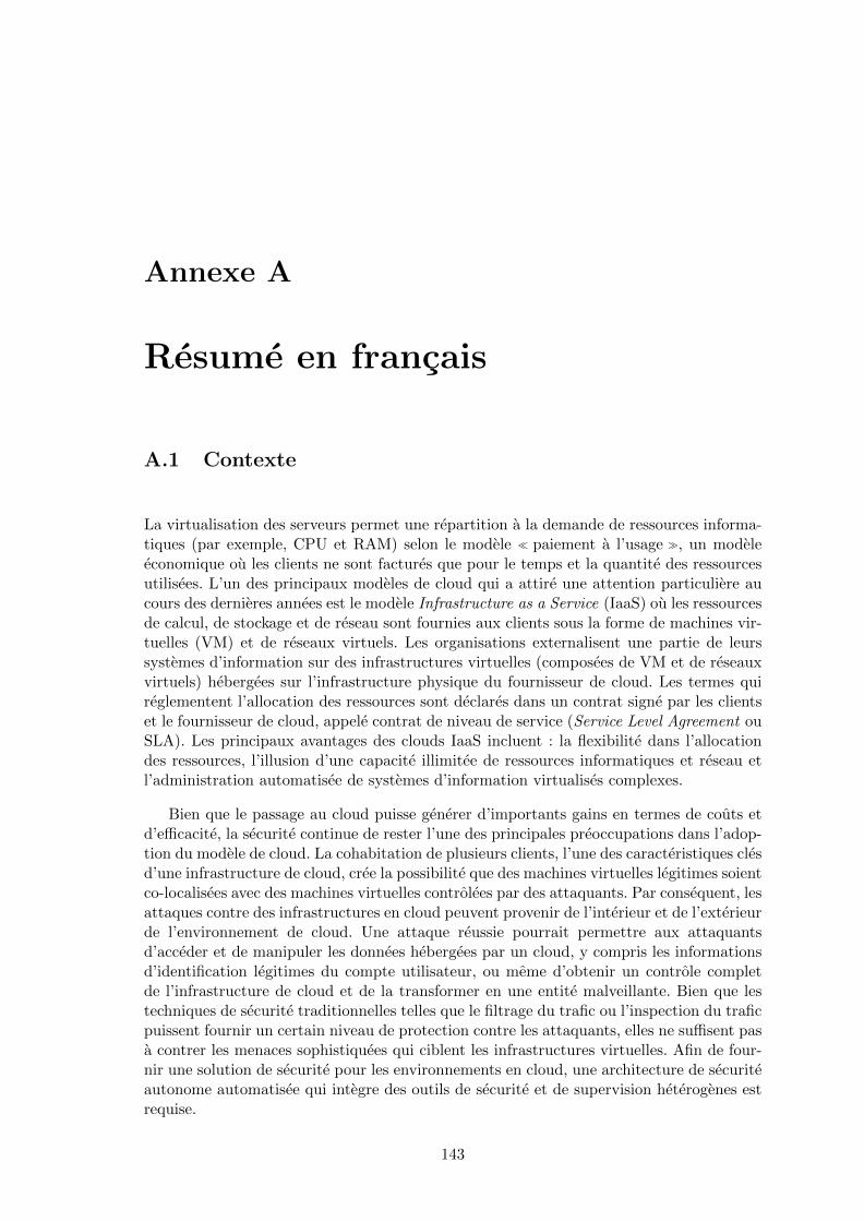
Annexe A
Resume en francais
A.1 Contexte
La virtualisation des serveurs permet une repartition a la demande de ressources informa-tiques (par exemple, CPU et RAM) selon le modele � paiement a l’usage �, un modeleeconomique ou les clients ne sont factures que pour le temps et la quantite des ressourcesutilisees. L’un des principaux modeles de cloud qui a attire une attention particuliere aucours des dernieres annees est le modele Infrastructure as a Service (IaaS) ou les ressourcesde calcul, de stockage et de reseau sont fournies aux clients sous la forme de machines vir-tuelles (VM) et de reseaux virtuels. Les organisations externalisent une partie de leurssystemes d’information sur des infrastructures virtuelles (composees de VM et de reseauxvirtuels) hebergees sur l’infrastructure physique du fournisseur de cloud. Les termes quireglementent l’allocation des ressources sont declares dans un contrat signe par les clientset le fournisseur de cloud, appele contrat de niveau de service (Service Level Agreement ouSLA). Les principaux avantages des clouds IaaS incluent : la flexibilite dans l’allocationdes ressources, l’illusion d’une capacite illimitee de ressources informatiques et reseau etl’administration automatisee de systemes d’information virtualises complexes.
Bien que le passage au cloud puisse generer d’importants gains en termes de couts etd’efficacite, la securite continue de rester l’une des principales preoccupations dans l’adop-tion du modele de cloud. La cohabitation de plusieurs clients, l’une des caracteristiques clesd’une infrastructure de cloud, cree la possibilite que des machines virtuelles legitimes soientco-localisees avec des machines virtuelles controlees par des attaquants. Par consequent, lesattaques contre des infrastructures en cloud peuvent provenir de l’interieur et de l’exterieurde l’environnement de cloud. Une attaque reussie pourrait permettre aux attaquantsd’acceder et de manipuler les donnees hebergees par un cloud, y compris les informationsd’identification legitimes du compte utilisateur, ou meme d’obtenir un controle completde l’infrastructure de cloud et de la transformer en une entite malveillante. Bien que lestechniques de securite traditionnelles telles que le filtrage du trafic ou l’inspection du traficpuissent fournir un certain niveau de protection contre les attaquants, elles ne suffisent pasa contrer les menaces sophistiquees qui ciblent les infrastructures virtuelles. Afin de four-nir une solution de securite pour les environnements en cloud, une architecture de securiteautonome automatisee qui integre des outils de securite et de supervision heterogenes estrequise.
143

144 ANNEXE A. RESUME EN FRANCAIS
A.2 Motivation
Dans un environnement de cloud IaaS typique, le fournisseur est responsable de la gestionet de la maintenance de l’infrastructure physique, alors que les clients ne sont responsablesque de la gestion de leur propre systeme d’information virtualise. Les clients peuventprendre des decisions concernant le cycle de vie des VMs et deployer differents typesd’applications sur les VMs fournies. Etant donne que les applications deployees peuventavoir acces a des informations sensibles ou effectuer des operations critiques, les clientss’occupent de superviser la securite de leur infrastructure virtualisee. Ces preoccupationspeuvent s’exprimer sous la forme d’exigences relatives a la surpervision de securite, c’est-a-dire la surveillance d’actions de types specifiques de menaces dans l’infrastructure vir-tualisee. Les solutions de supervision de securite pour les environnements en clouds sontgeneralement gerees par le fournisseur du cloud et sont constituees d’outils heterogenespour lesquels une configuration manuelle est requise. Afin de fournir des resultats dedetection corrects, les solutions de surpervision doivent tenir compte du profil des ap-plications deployees par le client ainsi que des exigences specifiques de securite des clients.
Un environnement en cloud presente un comportement tres dynamique avec des chan-gements qui se produisent a differents niveaux de l’infrastructure de cloud. Malheureuse-ment, ces changements affectent la capacite d’un systeme de supervision de securite ducloud a detecter avec succes les attaques et a preserver l’integrite de l’infrastructure encloud. Les solutions existantes de supervision de securite des clouds ne permettent pas deprendre en compte les changements et de prendre les decisions necessaires concernant lareconfiguration des dispositifs de securite. En consequence, de nouveaux points d’entreepour les attaquants sont crees, ce qui peut entraıner une compromission de l’infrastructureentiere du cloud. A notre connaissance, il n’existe toujours pas de systeme de supervisionde securite capable d’adapter ses composants en fonction des differents changements quise produisent dans un environnement de cloud.
L’objectif de cette these est de concevoir et mettre en œuvre un systeme de supervisionde securite auto-adaptatif capable de reagir aux evenements dynamiques qui se produisentdans une infrastructure en cloud et d’adapter ses composants afin de garantir un niveauadequat de supervision de securite pour les infrastructures virtuelles des clients.
A.3 Objectifs
Apres avoir presente le contexte et la motivation de cette these, nous proposons maintenantun ensemble d’objectifs pour un systeme de supervision de securite auto-adaptatif.
A.3.1 Auto-adaptation
Un systeme de supervision de securite auto-adaptatif devrait pouvoir adapter ses compo-sants en fonction de differents types d’evenements dynamiques qui se produisent dans uneinfrastructure de cloud. Le systeme devrait considerer ces evenements comme des sourcesd’adaptation et prendre en consequence des mesures qui reconfigurent ses composants. Leprocessus d’adaptation peut modifier la configuration des dispositifs de supervision exis-tants ou en creer d’autres. Le systeme peut decider de modifier les quantites de ressourcesinformatiques disponibles pour un dispositif de supervision (ou un sous-ensemble de dis-positifs de supervision) afin de maintenir un niveau de supervision adequat. L’adaptationde la quantite de ressources informatiques devrait egalement etre effectuee afin de libererdes ressources sous-utilisees. Le systeme devrait prendre des decisions d’adaptation afin

A.4. CONTRIBUTIONS 145
de garantir un equilibre entre securite, performance et cout a tout moment. Les actionsd’adaptation peuvent affecter differents composants et le systeme devrait pouvoir effectuerces actions en parallele.
A.3.2 Personnalisation
Les exigences relatives aux clients et concernant les cas de surpervision specifiques de-vraient etre prises en compte dans un systeme de supervision de securite auto-adaptatif. Lesysteme devrait etre en mesure de garantir une supervision adequate des types specifiquesde menaces demandes par le client. Une demande de supervision pourrait se referer a l’in-frastructure virtuelle complete d’un client ou a un sous-ensemble specifique de machinesvirtuelles. Le systeme devrait fournir le type de supervision demande jusqu’a ce que lademande du client change ou que les machines virtuelles auxquelles le type de supervisionest applique n’existent plus. En outre, le systeme devrait prendre en compte les seuilsdefinis par le clients (par des SLA specifiques) qui font reference a la qualite du service desupervision ou a la performance de types specifiques de dispositifs de supervision.
A.3.3 Securite et correction
Le deploiement d’un systeme de supervision de securite auto-adaptatif ne devrait pasajouter de nouvelles vulnerabilites dans l’infrastructure virtuelle supervisee ou dans l’in-frastructure du fournisseur. Le processus d’adaptation et les entrees qu’il requiert ne de-vraient pas creer de nouveaux points d’entree pour un attaquant. En outre, un systeme desupervision de securite auto-adaptatif devrait pouvoir garantir qu’un niveau de supervisionadequat soit maintenu tout au long du processus d’adaptation. Le processus d’adaptationne devrait pas interferer avec la capacite du systeme a detecter correctement les menaces.
A.3.4 Minimisation des couts
Le deploiement d’un systeme de supervision de securite auto-adaptatif ne devrait pasavoir d’impact significatif sur le compromis entre securite et cout pour les clients et lefournisseur. Du cote du client, un systeme de supervision de securite auto-adaptatif nedevrait pas influer de maniere significative sur les performances des applications hebergeesdans l’infrastructure virtuelle, quel que soit le profil de l’application (utilisant beaucoup lesCPUs ou beaucoup le reseau). Du cote du fournisseur, la capacite de generer des profits enlouant ses ressources informatiques ne devrait pas etre affectee de maniere significative parle systeme. Le deploiement d’un tel systeme ne devrait pas imposer de penalite importantedans les operations normales du cloud (par exemple, migration de VM, creation, etc.). Enoutre, la proportion des ressources informatiques dediees aux composants du systeme auto-adaptatif devrait refleter un accord entre les clients et le fournisseur pour la distributiondes ressources informatiques.
A.4 Contributions
Afin d’atteindre les objectifs presentes dans la section precedente, nous concevons unsysteme de supervision de securite auto-adaptatif capable de depasser les limites dessystemes de supervision existants et de gerer les evenements dynamiques qui se produisentdans une infrastructure en cloud. Dans cette these, nous detaillons comment nous avonsconcu, mis en œuvre et evalue nos contributions : un systeme generique de supervision de

146 ANNEXE A. RESUME EN FRANCAIS
securite auto-adaptatif et deux instanciations avec des systemes de detection d’intrusionet des pare-feu.
A.4.1 Un systeme de supervision de securite auto-adaptatif
Notre premiere contribution est la conception d’un systeme de supervision de securite auto-adaptatif capable de modifier la configuration de ses composants et d’adapter la quantite deressources informatiques disponibles selon le type d’evenement dynamique qui se produitdans une infrastructure de cloud. Notre systeme realise l’adaptation automatique et la per-sonnalisation en fonction des clients tout en fournissant un niveau adequat de supervisionde la securite grace au processus d’adaptation. Notre systeme comprend les composantssuivants : le gestionnaire d’adaptation (ou Adaptation Manager), les sondes de supervisiond’infrastructure (ou Infrastructure Monitoring Probes), la base de donnees de dependances(ou Dependency Database), l’API cote client et enfin les dispositifs de securite. Le gestion-naire d’adaptation est au cœur de notre systeme et est charge de prendre les decisionsd’adaptation lorsque des evenements dynamiques se produisent. Les sondes de supervisiond’infrastructure sont capables de detecter des evenements dynamiques lies a la topolo-gie et de transmettre toutes les informations necessaires au gestionnaire d’adaptation. Labase de donnees de dependances est utilisee afin de stocker des informations importantesconcernant les dispositifs de securite, tandis que, via l’API cote client, les clients peuventexprimer leurs propres exigences de supervision de securite. Enfin, les dispositifs de securiteassurent differentes fonctionnalites de supervision de securite.
A.4.2 SAIDS
Notre deuxieme contribution constitue la premiere instanciation de notre systeme et estaxee sur les systemes de detection d’intrusion en reseau (NIDS). Les NIDS sont deselements cles d’une infrastructure de supervision de securite. SAIDS atteint les objectifs aucœur de notre systeme tout en fournissant une solution passant a l’echelle pour repondreaux necessites d’adaptation paralleles. Notre solution est capable de passer a l’echelle enfonction de la charge du trafic surveille et de la taille de l’infrastructure virtuelle. Lescomposants principaux de SAIDS sont : le pilote d’adaptation maıtre (ou Master Adap-tation Driver), le travailleur d’adaptation (ou Adaptation Worker) et les capteurs locauxde detection d’intrusion (LIDS). Le Master Adaptation Driver est charge de la traductiondes arguments d’adaptation en des parametres de configuration pour les LIDSs alors quele travailleur d’adaptation est charge d’effectuer la reconfiguration en tant que telle desLIDSs. Les capteurs locaux de detection d’intrusion sont les dispositifs de securite quieffectuent la detection reelle des evenements de securite. SAIDS maintient un niveau dedetection adequat tout en minimisant le cout en termes de consommation de ressourceset de performance des applications deployees. Nous avons evalue la capacite de SAIDS aobtenir un compromis entre les performances, les couts et la securite. Notre evaluationconsiste en differents scenarios qui representent des environnements de production. Lesresultats obtenus demontrent que notre prototype passe a l’echelle et peut gerer plusieurscapteurs de detection d’intrusion reseau en parallele. SAIDS impose des couts addition-nels negligeables pour les applications des clients ainsi que pour des operations de cloudtypiques telles que la migration de VM. En outre, nous avons prouve que SAIDS maintientun niveau de detection adequat au cours du processus d’adaptation.

A.5. PERSPECTIVES 147
A.4.3 AL-SAFE
Notre troisieme contribution constitue la deuxieme instanciation de notre systeme et estaxee sur les pare-feu applicatifs. AL-SAFE utilise l’introspection de machine virtuelle afinde creer un pare-feu securise qui fonctionne a l’exterieur de la machine virtuelle sur-veillee mais conserve la visibilite intra-VM. AL-SAFE suit une strategie d’introspectionperiodique et permet au client de specifier la periode d’introspection. Les jeux de reglesappliques par le pare-feu sont adaptes en fonction des evenements dynamiques qui se pro-duisent dans une infrastructure virtuelle. Les composants principaux d’AL-SAFE sont :l’agent d’extraction d’informations (ou Information Extraction Agent), le composant d’in-trospection de machine virtuelle (ou Virtual Machine Introspection), les generateurs deregles (ou Rule Generators) et deux pare-feu distincts. L’agent d’extraction d’informa-tions est charge d’identifier les processus autorises a etablir des connexions alors quele composant Virtual Machine Introspection effectue l’introspection en tant que telle dela VM supervisee. Les generateurs de regles sont utilises pour produire les regles pourles deux pare-feux. Nous avons evalue la capacite d’AL-SAFE a proposer un compromisequilibre entre securite, performance et cout. Notre processus d’evaluation se compose dedifferents scenarios qui representent des environnements de production. Les resultats obte-nus demontrent que AL-SAFE est capable de bloquer toutes les connexions non autoriseeset que les regles resultant du processus d’adaptation sont correctes et operationnelles. Lescouts additionnels d’AL-SAFE pour les operations typiques du cloud, comme la migrationde VM, sont independants de l’intensite de l’activite de la VM, tandis que les couts ad-ditionnels pour les applications des clients dependent de la periode d’introspection et duprofil d’application (reseau ou calcul).
A.5 Perspectives
Nous avons identifie plusieurs axes de recherche pour les travaux futurs. Nous les organisonssur des objectifs a court, moyen et long terme.
A.5.1 Perspectives a court terme
Nos objectifs a court terme se concentrent sur les ameliorations de conception et de miseen œuvre des versions actuelles de nos prototypes ainsi que sur la mise en œuvre de deuxdes composants de notre systeme que nous n’avons pas eu le temps de mettre en œuvre.Dans SAIDS, nous souhaitons ajouter des decouvertes automatiques de service afin que lesregles de detection liees aux services executes, et appliquees dans les LIDSs affectes, soientautomatiquement adaptees. Le mecanisme d’introspection d’AL-SAFE pourrait etre utilisecomme outil de decouverte automatique des services. Dans AL-SAFE, nous souhaitonsremplacer le modele d’introspection periodique par un modele d’introspection declencheepar des evenements, de sorte que les couts additionnels dans les applications des clientssoient reduits. Enfin, nous souhaitons mettre en œuvre deux autres composants de notresysteme, la base de donnees de dependances et l’API cote client.
A.5.2 Perspectives a moyen terme
Nos objectifs a mi-parcours visent a aborder des problemes plus complexes qui sont in-trinseques aux environnements de cloud, comme la cohabition des clients. La version ac-tuelle de notre systeme de supervision de securite ne traite pas des problemes qui se posentdans les environnements multi-clients. Afin de permettre la supervision de la securite pour

148 ANNEXE A. RESUME EN FRANCAIS
differents clients, nous devons considerer le partage des dispositifs de supervision entre lesclients. Le partage de dispositifs entre les clients peut egalement etre percu comme unaspect supplementaire de la reduction des couts. Nous souhaitons etudier les changementsnecessaires tant dans SAIDS que dans AL-SAFE afin d’atteindre cet objectif. En outre,nous souhaitons inclure d’autres types de LIDS comme les systemes de detection d’intru-sion hote et les analyseurs de reseau dans le prototype SAIDS. Les autres perspectives derecherche a moyen terme incluent la combinaison de la supervision de la securite des clientset du fournisseur ainsi que l’integration de SAIDS dans un systeme a grande echelle, gracea une collaboration avec la startup Qirinus.
A.5.3 Perspectives a long terme
Dans une perspective a long terme, nous nous interessons a la conception d’un systeme desupervision de securite auto-adaptatif entierement autonome. Un systeme de supervisionentierement autonome devrait pouvoir reagir aux evenements de securite et prendre desmesures en consequence afin d’isoler les machines virtuelles potentiellement infectees etempecher les attaquants de prendre le controle de l’infrastructure virtuelle. La reactionrepose essentiellement sur la capacite du systeme a traduire les resultats de la supervisionde securite (par exemple, les alertes des systemes de detection d’intrusion) en des decisionsd’adaptation qui reconfigurent des dispositifs de supervision. Dans le contexte de cettethese, une telle capacite est liee a l’inclusion d’evenements de securite dans l’ensembledes sources d’adaptation possibles. Actuellement, notre systeme de supervision de securiteauto-adaptatif prend en charge l’adaptation des dispositifs de securite en fonction de troistypes d’evenements dynamiques : ceux lies a la topologie, aux services deployes, et a lacharge de travail en analyse. Les evenements de securite (c’est-a-dire les attaques) en tantque source d’adaptation potentielle n’ont pas ete pris en compte.

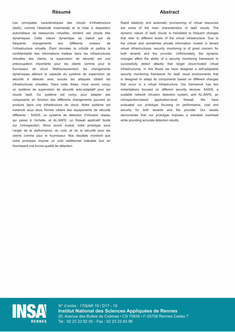
Institut National des Sciences Appliquées de Rennes20, Avenue des Buttes de Coëmes CS 70839 F-35708 Rennes Cedex 7Tel : 02 23 23 82 00 - Fax : 02 23 23 83 96
N° d’ordre : 17ISAR 19 / D17 - 19
Résumé
Les principales caractéristiques des clouds d’infrastructure(IaaS), comme l’élasticité instantanée et la mise à dispositionautomatique de ressources virtuelles, rendent ces clouds trèsdynamiques. Cette nature dynamique se traduit par defréquents changements aux différents niveaux del’infrastructure virtuelle. Étant données la criticité et parfois laconfidentialité des informations traitées dans les infrastructuresvirtuelles des clients, la supervision de sécurité est unepréoccupation importante pour les clients comme pour lefournisseur de cloud. Malheureusement, les changementsdynamiques altèrent la capacité du système de supervision desécurité à détecter avec succès les attaques ciblant lesinfrastructures virtuelles. Dans cette thèse, nous avons conçuun système de supervision de sécurité auto-adaptatif pour lesclouds IaaS. Ce système est conçu pour adapter sescomposants en fonction des différents changements pouvant seproduire dans une infrastructure de cloud. Notre système estinstancié sous deux formes ciblant des équipements de sécuritédifférents : SAIDS, un système de détection d’intrusion réseauqui passe à l’échelle, et AL-SAFE, un firewall applicatif fondésur l’introspection. Nous avons évalué notre prototype sousl’angle de la performance, du coût, et de la sécurité pour lesclients comme pour le fournisseur. Nos résultats montrent quenotre prototype impose un coût additionnel tolérable tout enfournissant une bonne qualité de détection.
Abstract
Rapid elasticity and automatic provisioning of virtual resourcesare some of the main characteristics of IaaS clouds. Thedynamic nature of IaaS clouds is translated to frequent changesthat refer to different levels of the virtual infrastructure. Due tothe critical and sometimes private information hosted in tenantvirtual infrastructures, security monitoring is of great concern forboth tenants and the provider. Unfortunately, the dynamicchanges affect the ability of a security monitoring framework tosuccessfully detect attacks that target cloud-hosted virtualinfrastructures. In this thesis we have designed a self-adaptablesecurity monitoring framework for IaaS cloud environments thatis designed to adapt its components based on different changesthat occur in a virtual infrastructure. Our framework has twoinstantiations focused on different security devices: SAIDS, ascalable network intrusion detection system, and AL-SAFE, anintrospection-based application-level firewall. We haveevaluated our prototype focusing on performance, cost andsecurity for both tenants and the provider. Our resultsdemonstrate that our prototype imposes a tolerable overheadwhile providing accurate detection results.