selection, modification and analysis of suspension system for an all
TRANSCRIPT

ISSN : 2319 – 3182, Volume-2, Issue-4, 2013
62
Selection, Modification and Analysis of Suspension
System for an All-Terrain Vehicle
Eshaan Ayyar, Isaac de Souza, Aditya Pravin, Sanket Tambe, Aqleem Siddiqui & Nitin Gurav E-mail : [email protected], [email protected], [email protected], [email protected]
Abstract - The real pleasure of driving for an off-road
enthusiast can be described as the thrill of the terrain
coupled with a capable machine to handle the terrain.
However, this pleasure can be derived only when the
comfort level of the driver is maintained. Thus, it is
concluded that the suspension system (which is responsible
for providing a comfortable ride quality to the driver) is
one of the most important sub-systems to be designed. This
paper aims at selecting, modifying, analyzing and
fabricating a suspension system capable of handling rough
terrains while maintaining the ride quality.
I. INTRODUCTION
Suspension system is the term given to the system
of springs, shock absorbers and linkages that connect a
vehicle to its wheels.When a tire hits an obstruction,
there is a reaction force and the suspension system tries
to reduce this force. The size of this reaction force
depends on the unsprung mass at each wheel assembly.
In general, the larger the ratio of sprung weight to
unsprung weight, the less the body and vehicle
occupants are affected by bumps, dips, and other surface
imperfections such as small bridges. A large sprung
weight to unsprung weight ratio can also impact vehicle
control.
The main role of suspension system is as follows:
It supports the weight of the vehicle
Provides a smoother ride for the passengers
Protects the vehicle from damage
Keeps the wheels firmly pressed to the ground for
better traction
It isolates the vehicle from road shocks
There are three basic components in any suspension
system:
Springs
Dampers
Anti-sway bars
The following types of suspension systems are
generally available in the market:
1. Mechanical Suspension System:
i) Independent Suspension
Leaf Spring Suspension
MacPherson Suspension
Wishbone Suspension
ii) Dependent Suspension
Rigid Axle Suspension
2. Electric Suspension System
3. Magnetic Suspension System
II. SELECTION OF SUITABLE SUSPENSION
SYSTEM
The selection of the suspension system which will
best satisfy the requirements of an ATV was carried out.
Out of the many available suspension systems in the
market, the Double Wishbone Suspension System was
selected for the ATV. This selection was done based on
the following basic parameters:
1. Load bearing capacity
2. Flexibility
3. Cost
4. Technical aspects: Camber, Stiffness, Rolling
5. Availability of parts and components
III. DESIGN
The design procedure for the chosen suspension
system is divided into two stages:
1. Primary design:
Basic design and development of Suspension
System components
International Journal on Theoretical and Applied Research in Mechanical Engineering (IJTARME)
ISSN : 2319 – 3182, Volume-2, Issue-4, 2013
63
Modified design parameters based on
approximation of Dynamic Conditions
Static testing and analysis
2. Secondary design:
Mathematical modeling of finalized concept ATV
Dynamic testing and analysis
Modification of Design Parameters based on
Dynamic Testing results
The following components are to be designed:
Suspension Spring
Wishbones
Knuckle
Design procedure for the components of Suspension
system is dependent on the suspension geometry (as
shown in Fig.1 and Fig.2); found out by taking into
considerations the design constraints.
Fig.1 Front suspension geometry
Fig.2 Rear suspension geometry
Design of suspension spring
Assumptions made:
Sprung mass = 260 kg(approx.)
Factor for static to dynamic conditions : 2.5
According to the mass distribution of 60:40 (Rear:
Front)
Mass per wheel (Front) = 50 kg
Mass per wheel (Rear) = 80 kg
1) Front spring
Angle of inclination of the strut = 60 (from horizontal)
Point of attachment of strut = 10” (254 cm) from chassis
end ….(from suspension geometry)
Reaction force acting from the ground on the wheel =
(Mass per wheel * 9.81) N
= (50 kg * 9.81) N
= 490.5 N
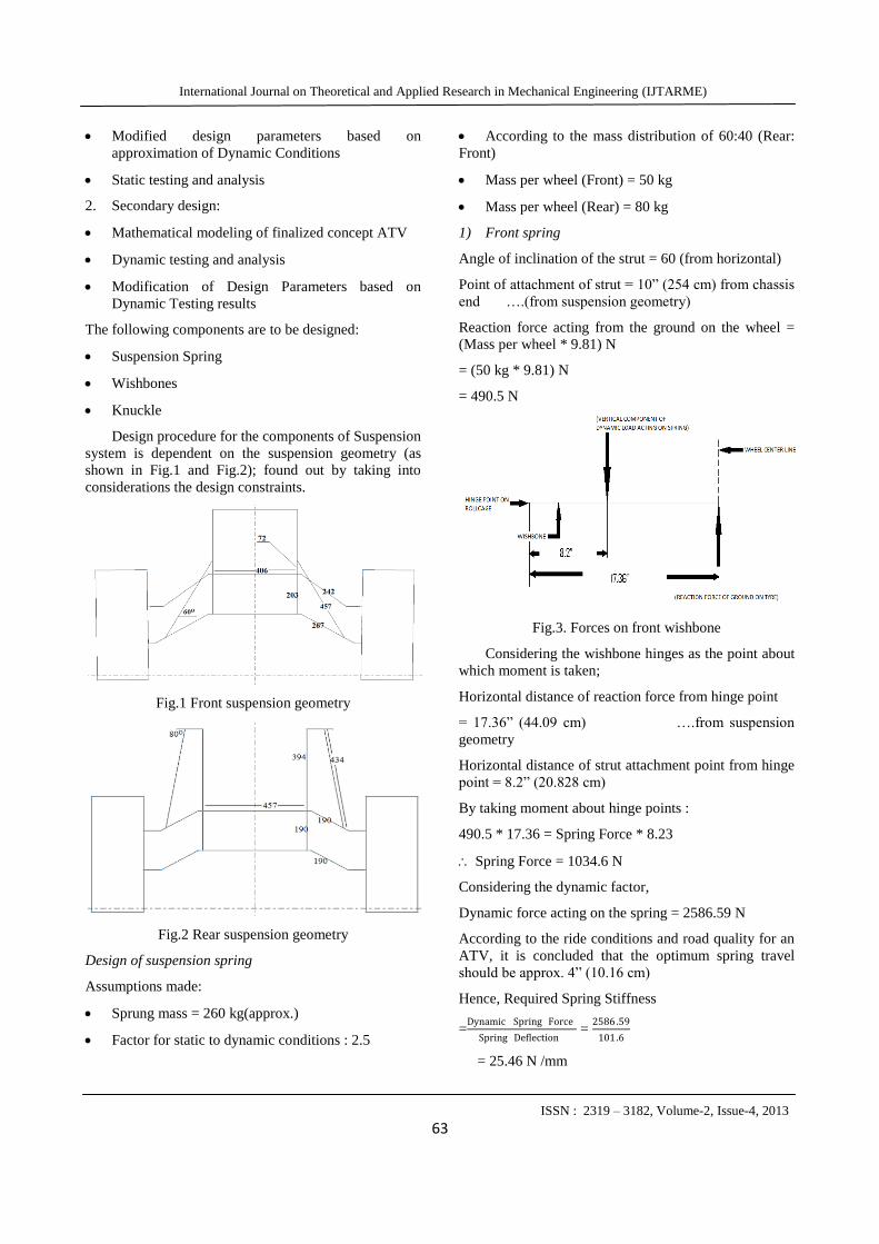
Fig.3. Forces on front wishbone
Considering the wishbone hinges as the point about
which moment is taken;
Horizontal distance of reaction force from hinge point
= 17.36” (44.09 cm) ….from suspension
geometry
Horizontal distance of strut attachment point from hinge
point = 8.2” (20.828 cm)
By taking moment about hinge points :
490.5 * 17.36 = Spring Force * 8.23
Spring Force = 1034.6 N
Considering the dynamic factor,
Dynamic force acting on the spring = 2586.59 N
According to the ride conditions and road quality for an
ATV, it is concluded that the optimum spring travel
should be approx. 4” (10.16 cm)
Hence, Required Spring Stiffness
=Dynamic Spring Force
Spring Deflection =
2586 .59
101.6
= 25.46 N /mm

International Journal on Theoretical and Applied Research in Mechanical Engineering (IJTARME)
ISSN : 2319 – 3182, Volume-2, Issue-4, 2013
64
25 N/mm
2) Rear spring
Angle of inclination of the strut = 80o (from horizontal)
Point of attachment of strut = 6.5” (16.51 cm) from
chassis end …(from suspension geometry)
Reaction force acting from the ground on the wheel
= (Mass per wheel * 9.81) N
= (80 kg * 9.81) N
Fig.4. Forces on rear wishbone
Considering the wishbone hinges as the point about
which moment is taken;
Horizontal distance of reaction force from hinge point =
14” (35.56 cm) …..(from suspension geometry)
Horizontal distance of strut attachment point from hinge
point = 6.38” (16.02 cm)
By taking moment about hinge points :
784.8 * 14 = Spring Force * 6.38
Spring Force = 1722.13 N
Considering the dynamic factor,
Dynamic force acting on the spring = 4305.325 N
According to the ride conditions and road quality for an
ATV, it is concluded that the optimum spring travel
should be approx. 4” (10.16 cm)
Hence, Required Spring Stiffness
= =
= 42.375 N
40 N/mm
Table 1. Spring dimensions
Sr.
No.
Parameter Front
Suspension
Rear
Suspension
Material Grade 4 oil hardened spring steel
1 Wire diameter 11 mm 11 mm
2 Inner coil
diameter
55 mm 55 mm
3 Outer coil
diameter
66 mm 66 mm
4 Total number
of turns
22 14
5 Free length of
strut
365 mm 292 mm
6 Pitch of
suspension
spring
18 mm 27 mm
7 Eye-to-eye
length of strut
(unloaded)
456 mm 484 mm
8 Stiffness 25 N/mm 40 N/mm
9 Maximum
dynamic spring
travel
101.12 mm 100.88 mm
B. Design of wishbones
The design parameters that govern the dimensions of the
wishbone are :
i) Available length for wishbones: 32 inches
ii) Available width for wishbones: 20 inches
1) Front wishbone
The front wishbones are standard A-arms and the
dimensions are decided on the basis of the length and
width constrains (as shown in Fig.5). The wishbones
have unequal length.The upper wishbone is shorter than
the lower wishbone.The advantage of having different
lengths is that when the car takes a turn a negative
camber is induced which increases the stability.The
unequal lengths also result in a positive camber of
1.5⁰.The strut is mounted on the lower wishbone and the
knuckle is attched to the wishbone by a ball joint. The
wishbone is then tested using Autodesk Inventor.

International Journal on Theoretical and Applied Research in Mechanical Engineering (IJTARME)
ISSN : 2319 – 3182, Volume-2, Issue-4, 2013
65
Fig.5.Front Wishbone
2) Rear wishbone
Initially, the A-arm was considered for the rear
suspension. However, while the vehicle takes a turn, due
to the horizontal forces acting on the attachments of the
wishbones and the knuckle and due to lack of steering
on the rear wheels, there may be toe-in or toe-out of the
wheels. This may lead to improper steering and may
result in unbalance. Excess toe-in may cause oversteer
while turning leading to loss of control. Excess toe-out
may cause understeering while turning.To avoid any
toeing, the A-arm is converted into H-arm (as shown in
Fig.6). Thus the vertical pin knuckle-wishbone
attachment is converted into horizontal pin attachment.
This prevents formation of an axis and hence the
possibility of toeing of the wheels. This ensures proper
alignment and steering. It also increases the ride stability
and linear travel.
Fig.6.Rear Wishbone
C. Design of knuckle
A knuckle is used to connect the wishbones to the
wheel hub.
1) Front knuckle
The first step in the design was market research. A
standard knuckle of MARUTI SUZUKI ESTEEM was
selected from the market and studied. The suspension
system of the Esteem is MacPherson type, hence the
knuckle had to be modified. The designed knuckle is
shown. (Fig.7)
Fig.7.Front Knuckle
Due to lack of funds the above design could not be
manufactured.The knuckle of a maruti 800 was
modified so that it could accmmodate the designed
wishbones.The modified design is shown below.
Fig.8.Modified Front Knuckle
2) Rear knuckle
The rear knuckle was designed to accommodate the
designed H-arms (Fig.9)
Fig.9.Rear Knuckle

International Journal on Theoretical and Applied Research in Mechanical Engineering (IJTARME)
ISSN : 2319 – 3182, Volume-2, Issue-4, 2013
66
The rear knuckle too could not be manufactured due to
lack of funds.the knuckle of an esteem was modified as
shown in the figure
Fig.10.Modified Rear Knuckle
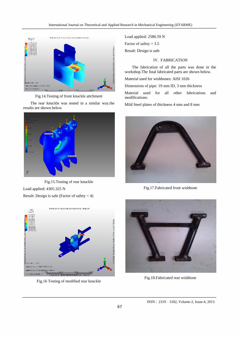
TESTING OF DESIGNED COMPONENTS
Analysis of all the parts was done using Autodesk
inventor.
Wishbones
The front lower wishbone was tested as the strut is
attached on the lower wishbone due to which most of
the load acts on the lower wishbone. The wishbone was
tested on Autodesk inventor. The two hinge points and
ball joint were considered as fixed points and a load of
2586.59 N(load on spring) was applied at the strut
attchment point.
Fig.11.Front Wishbone
Load applied: 2586.59 N
Factor of safety: 1.5
Result: Design is safe
The rear upper wishbone was tested as the strut
attachment point was on the upper wishbone. The hinges
were considered as fixed points and a load of 4305.325
N was applied at the strut attachment point.
Fig.12.Rear Wishbone
Load applied: 4305.325 N
Factor of safety: 1.5
Result: Design is safe
B. Knuckles
The hub end of the knuckle was considered fixed
and a load of 2586.95 N was applied at the lower part of
the knuckle as shown in fig.13.
Fig.13.Testing of front knuckle
Load applied: 2586.59 N
Factor of safety = 3.5
Result: Design is safe
The attchment for the front knuckle was tested and the
result (Fig 14).
International Journal on Theoretical and Applied Research in Mechanical Engineering (IJTARME)
ISSN : 2319 – 3182, Volume-2, Issue-4, 2013
67
Fig.14.Testing of front knuckle attchment
The rear knuckle was tested in a similar way.the
results are shown below
Fig.15.Testing of rear knuckle
Load applied: 4305.325 N
Result: Design is safe (Factor of safety = 4)
Fig.16 Testing of modified rear knuckle
Load applied: 2586.59 N
Factor of safety = 3.5
Result: Design is safe
IV. FABRICATION
The fabrication of all the parts was done in the
workshop.The final fabricated parts are shown below.
Material used for wishbones: AISI 1026
Dimensions of pipe: 19 mm ID, 3 mm thickness
Material used for all other fabrications and
modifications:
Mild Steel plates of thickness 4 mm and 8 mm
Fig.17.Fabricated front wishbone
Fig.18.Fabricated rear wishbone
International Journal on Theoretical and Applied Research in Mechanical Engineering (IJTARME)
ISSN : 2319 – 3182, Volume-2, Issue-4, 2013
68
Fig.19 Front knuckle with attachment
Fig.20 Rear Suspension
Fig 20. Final Assembly
V. REFERENCES
[1] Christina Elena Popa, ‘Steering System and
Suspension System’, University Of South
Queensland
[2 ] Edmund F. Gaffney and Anthony R. Salinas,
‘Introduction to Formula SAE Suspension’,
University Of Missouri
[3] Mitchell W., ‘Force based roll centres and
kinematic roll centres’, SAE-India
[4] Gertz L., L. Laranja, ‘An off-road suspension
system’, University Of Brazil
[5] Gerrard M., ‘Roll centres and jacking forces’,
Engineering Solutions
[6] NK Giri, ‘Automobile Mechanics’, Khanna
Publications, 1996
[7] Kirpal Singh, ‘Automobile Engineering’,
Standard Publishers Distributors, 2008
[8] Thomas D.Gillespie, ‘Fundamentals of Vehicle
Dynamics’
[9] T.K. Garrett, K. Newton, W. Steeds, ‘The Motor
Vehicle’, Butterworth-Heinemann, 2000
[10] Design Data Book, PSG Technology Institute