seivice · 2011-05-13 · ad-a021 833 terminal ballistics marvin e. backman naval weapons center...
TRANSCRIPT

AD-A021 833
TERMINAL BALLISTICS
Marvin E. Backman
Naval Weapons CenterChina Lake, California
February 1976
Reproduced FromBest Available Copy
DISTRIBUTED BY:
Wadion~l Technicl Ift m •i SeiviceU. S. DEPARTMENT OF MCMERCE
cD ii)O 0 o

Y_____ IMF- ~ - ~ - - -
I'IT
p~NAYRONAL ThHNICAL ,~ i*~1Of *"1ON Sr,.ICE
N.. S(PUAf( OF CC*1ý=U1w1z L VA.VIl

NV'ý TP 5780
Marvin E. BackmanResearch DepartmentNaval Weapons Center
February 1976
Arprtedd i-Public release; distribution unlhimited.
NavalWeaponsCenterChina LakeCalifornia 93555
a, xwc
:MA RWW76
* ~ J i/I)

NWC Technical Pulicadton S730
Published by ................... Technical Information Department
Collation .................................. Cover. 118 leavesFirst printing .......................... 500 unnumbered copies
)
Adtonal copies, at $12.50 each, available fromNational Technical Infot•nation Service
Springfield, Virginia 22161
t-"j.

77 77 77 7~'~- '- -' -
,W4CLASS777-
No RiMOM'uc~
lIrNiINAl. BALLISTICS
Chom~~~V LI.Cj~ý-9b
Ohw.. Labe. Cihforna. 9W6,
Uh4CLAWSIEIf
5?UJVC far ? 4k Me" .ftba
m newon"d (C- w*U t..e '*hb,"1.,en'.
A-m~o Pe.0fatoeE~pk~vn SL,Eoeronmtio. Shtowd Ckwtrm
SM it u of form.
is
ODiA'7W OU ~NCLA~SWIOfED 68
mo .04,gv=F-

EU)1) f y ua 2. bm Cho& L,.& C*.KMo Who Cmm. F no. i~1 ww Xx pp, 1?W 1, i
NM- UNCASS'U)(U) Two noun a m.~u -,AW n dmr at '3ý
Ofd b.e~ mi 6qmint of OWMN w~t do
md pkg do fm II a" an nft swuw a mow m
buhFp a pwM dmcmpeaof %aft pbomaL b doW patmau "MAnd a" of~c "wo am met ~I
ft dwdpýad oui b m of in$ *A bob Of fAt BWNN -VW hm low& *ad Nommo Wft
- LVOCLASSIFIED
swomu" eAwbu..alm ow "M pauda a-
w 1, wel li"I T 1
A" ACTIVIT OF TH-E NAM~L hAO413RA 0F**%,14tM G. FSP W.w 111. M~ M .......... CASWONS'idoG L "a~a~lpou, ..... . .. .....
Foreword
This book is based on lecture notes for a course offered at the NavalWeapon~s Center as part of its training program of day classes in scieece andengineering. Its publication was jointly sponsored by the ResearchDepartment and the Personnel and Organization Development Division.Personnel Depastment of NWC. The course was designed to summarize thefundamental concepts of terminil ballistics for employees who would usethe information directly in ass~gnments in research, development, or analysisof weapons. or who would use the information as background in theplanning and mwantement of weapons programs. For this audience terminalballistics is the science of the interaction of a ballistic weapon with a targetand must include sophisticated warheads as well as the classical concepts ofthe defeat of armor.
Typicaly the student was a recent engineering or physical sciencegraduate; however, m~any technicians who were directly involved in weapondesign and testing also took ine course. For these and many othersassociated with ordnance science, there is a continuing need for au'introductory summary of the main phenomena of tse detonation andfragmentation of explosive warheads and of the phenomeau of high-velocityimpact and the techniques for measuring and predicting the extremely rapidand intense exchanges of energy and nwmelatum that occur in theinteraction of a warhead with a target. Warhead design and analysis willoften require the devetlopmen t of these concepts beyond this introductory
* level. The object here is to provide the starting point from which thedirection for further development will be more clear.
The book begins with the ballistics of gun-launched projectiles, thesubject matter of classical ballistics, and devetps froim this base a paralleldescription of warhead phenomena. In this process parts of severalspecialized fields of physical science we used: impact mechanics, thedeflagratiem and detonation of explosives, and the behavior of materialsunder extremely high loads and high rates of' loading. Thus, in this

pE4YCsaufl Ingnl cuti"b~(a toI,,. ft eu~roit tchkohk)I4 the fchkLI i-.c~ipowed to A -. nrthc.i,, tot NpeLdIdtakeanot phv-ojl.Liek ' du~xth are notrc4&JaIV a%.Ailaboc and ire mot u'.ujII interre~late~d, but vrt~itha t tlw b"%u It*warhe~ad jna4fi .and %"egn.
wkw vUnjkr Authiwit% -A
JOHN PEARSON, lk~i It W MINTER, JA'cd
Detwanuhw, Ph)Wr . DIs ~ m R'tioth Thprinrt'nl
I Dicixembr 147i
ACKNOWLEDGMENT
The aultia %%heN, Ito .akrumlk~edgse Jv,.Laf'auc given b'% the
membcr, of ithe Dct~mnition PhvmjL. Da~.eni~o 0 Owe Ro-cneh Dcpylmint .atthe NaoaI Weiaptem Lcnttei thrtuu,~h Ji'Lu.%ttoun'. wlthickm* and crocteuare~rtwns~.
The cotiuio, %,I johoi PCeaf-Ain and CjIo Au~.1in asguc~t lea~uscis lp~flA:tu~lyI .aPIfWCitCd. The %C1tt4bf% ion %%jrtWJJ t,-jgfmtjti~trnp Jd %)eit .Androdk puencirmion are bhawed cera their Icitirsr'. IhianI iu due AI-An its toni
Goff leer peepiritiu. tot thc rintnu'.ripl. ltx- %i.ioen .andj ,.ernefn of tle,Ctonum~nd at the Nial W.'Jpeen% Cente~r o~hg~h hla been cmtwbdird in theSckenct and Enginee~ring Div, CIlo., Pitpreerrm Jte the twiginal prewntilteon%
ORM-WF.M /

......... ::.... . i : . : - - -: .. , . : .. , , . : • : , ' :. - ,1
S Contlent.11
..... ................ . ................ 4
Part I. Projectile Ballistics
1. T11 he mrir Ejlgics of Gans ......................... !1ignition ......................................... 13Chemistry and Thenrnmvrnamics of Burning ................ 14
Rate of Burning ................................... 22ProjW dii ACCelrIation After Burrngu ........................ 32Sum mary ......................................... 36
2. The ExeriuBr Balisics of Projectiles ....................... :-7Dynamics of a Projectile in Free Flight .. ................... 37Projectile 'fralectories.................................... 1Aerodynamic-. of a Projectile ............................ 41Summ y .. ........ ............................. 51
3. The Termina Ballistics of Ptojectiles..................... .. 53' Exampes of Target..s ................................. 53
ExarwFe. of Projectie ................................. 55Penetration Resstance oi Various Materials .................. 56
Penetration Into Soils .................................. 58Hilhtrength Barriers .. ................................ 71Application of Conservation Laws ......................... 76
Simple Terminal Balli~lics Theories ........................ 82Deflection and Ricochet ................................ 87Single Fragment Sytems ............................. 91Sum may ........................................ 9
/ '\

4. The AaukgV &"e.aha odGn...
Mani~n Phmwjo h L-mlo fjW~cJ....... 101
Fr~agumnt Pr--twitm , % i n .k-i~iic W ~ twij ... 11
ShoopeJ O u~ry . . .. . . . . .. . . .. .. . . 1;44
!Sumnury . . . . . . . . . . . . . . . 1
6. WartwAz Eotterim- Balis~icb an Bins .. . . . . .. . . . 41Emtewor Bdbn.ýIit~ of Wath-K-A I rimet ... . . . . . . . 1a2
BUm ......................... 144
7. TermWnn Ballistmic of WxrheAd ............. 1,)
Inpct bmo Mttctul ftcm the Wjrhtid Cj'sc .... ......
sujmm jqý . . . . . . . . . . . . . . . . . . .. 186
.. .. .. .. . .. .. .. . .. .. .. . .. . 18
Appgndii: The Behavior of %4aeviA~s Undxkv Impactmood Explosive LemANa .. . . . . . . . . . . . . . j95
Ineif%.................. .............................. 227

Introduction
So.n"ific mwthaud% hate been applied to the problem of improfing the
acLur,•.h ad range 41t gun-, tor at leJa two centutieN. A.n important part of
thi• eftort ha% been the prediction of the traltwore% of pfojeLtik" Irom the
vett ."d Lompoiion tIt the .iurge. •, w*eight and dhipe of the pro;ectilc.
amd the dinocngonrh and hlcitaion tit the gun bjrret. The data and thcoric%
needed tou ke thew.e predetion% aue Dart of the ,cienre of ballvtit.. The
event-. occurring in the barrel of the gun are ia~tI• ditfere.nt from the etert%
ocaurfrfn during free flight of the pIoiectile. Woth %ct% of evert% are ob0i-xJuA
important in determining icufji.a nao range. Kit the method% of anal, rfing
them are %utiicientlf different to make .%crate treitm.-nt useful and nerural.
Infornmution abiit the event% it, the barrel is caller1 interior badllistit-;
inforiition About everot, in free flight is caMtd eir•tferitr bul/ffits.
U.sitact between the puona.wtile and the target end% all cor.viderattton% ti
accurc; and range. The pro•ti.le impats againat the t)blect at the aimpoint.
and thlat obe•t lose%. it% meaning a% a tare•t and hti.orme important a' a
birrier. The interaction'. tf a pro~etle with a barrier that ire of moýýt m-*.;st
are the penetration into the barrier. or pa'..age of the protet.tile through the
barrier. Quantiuatt•e meT'aure', of t•hew. i)fltC~rttiorns are .orrdjtion% of
penetration depth to impact beho.t•. correlataii~n of res'idual %elocit' of the
proje•tile to the inp4.ilt Y.-bocitv, and the ballistic limit. wihich is the lowe"t
velocity for perforation. The-c are data on trai•.tmtwe,. ard the atud) of the
proiectite,'barrier interAtion completes the investigation (f projec-ile motion
begun under interior and e'.terioi balli.tac'. The %tudN of proitile'barrier
interaction- is called terminal bu/hitlcs.
Developrnments in military technology haie changed the method'. of
delivering weapons. Aerial btmb', and rockct-propelltd weapon% are now just

- - --
TERMINAL HALLISI1(5S
as, important is gun-fired w .rp4n-s. Interioi arid ev!erior o l~ il' ~rr rovif-'
the basis for -.Nstematic impriirsenlnt of th':ý aLt.L)r i-Ja' rangt of tfhe'4.
devices'. Yet another deselopment i'. the use of e' plosrsr', in Pro wiles. The
terminal phase of in e-,plosi~c projectile differ, drasticaLlI from th.1t oif Ar
inert projectile. The c~plosi~c esenl amnd it% coirsequenLCe are~ the new center
ofl interest. Pr-oIectile motion loses, much of its, i~npOrtxLCe in the
projectile narrier interac.tion. The ba~listic limit,. ne.netral ofl, and theories of
residual teloctit. which ire the essence of ;,.ojcctile terminal bjlfiStics, have
few Counterparts in c~pio'.ri~e phenomena, 5co that classic~il terminal ballistics
doe, little to c~plaini the workings of explosike pro jectiles.
The termni,iaf phase (of di esplodling tbalfftic weapon is comiposed ofesents that occur m list and under such intense forc'ý that it is diftiLeýlt toobserve the phenomena much to's arnal~ie them. I-or th;.N rr','son, any body or~
knowle'dge thit will help interpret these esents bý con-iparison or nant.rýcg- is
dcfinitelý neceud. The terminal ballistics ol inert p~oiei file-, i -) limiteA I.-
meet this need. 1heit: are, howeser, strong similarities r.veeri ra// o the
baffIistitk of itiert pro/etot- i/e nd the termrinal pht/.s' it ijf' e.xplosi.'e vKu'heud.The acceleration of fragmer.ls from the case of it,%! a.Oledd is like inle.-ior
ballisti4Ls, the flight ot fLagments to the target is like emterior ballistics, and
the interaction of the fraigments with the target as a barrier- is like termlinal
ballistics. Added ito thewe phoerndena oft fragment-, is the g.-Ieration,transmission, ind interaction trt blast with the t 'rget. Blast has ri )significant
counterpart in projectile ballistic s, but it is an aiddition that carl he considered
sepiratels without dctractirrg from the a15 v'tages gaincd by the analogy
between proje~tile and wxrhvad fragment.
To summari/e, the studs ilf the terminal phase of the operatloo of an
k:-.plosi-,e warhr.ad it, certainly nece!-ssary and will proftI from 'vstematic use of
inalogmv, but it is not lea-' ble ito base the .,I-jd\ of the A arh,.ad terminal phaseon the t~rmirial phase of projectile ballistics: rather, the whole of projecffe
ballistics is required. The warhead is a new ballistic system co~mplete withititerior, citterior, and terminal baillistic phases, and the study of this n'!w
systemn hius useful parallel% it) the proiecoile ballistic sysStem.
The *arhead and projectile ballisltic s-%stems hive a Lommor~ pu pose toconvert energy stored as, chemical energy into mechanical form and transfer
tile energy to a remorte target. ',he Iwo s% stemns differ most in the limitations
that are imposed on the energy transfer process. The projectile system involves
in energ\ transfer apparatus It" gun that must not bc damaged by the
process. The warhead systemn is co lmpfezely free of th.' limization, but it his
-7- 7.

i~qOLI'-I'm~ Pa
.e ,.*.,ta'on that every component of the energy trarsfer apparatus mustfurnction with maximum efficiency and minimum weight.
* The present treatment begins with a discussion of projectile ballistics.Onl-, those parts of interior and exterior ballistics of gun-fired projectiles thatare particularly rele~ant to warhead ballistics are discussed. (For example, thecompiexities of spin stabilization imparted by the rifled barrel are givenminimal attention, not because these are unimpcrtant in projec,!le ballistics,
but because there is little carry~wer into warhead ballistics.) Projectile terminalballist!cs is considered in greater detail. Warhead ballistics is developed byshowing the elaboration and modification of projectile interior ballistics that is
needed for explosive devices, the changes needed in exterior balstics, and *:e
changes needed in terminal ballistics to account for the special characteristicsof warhead fragments and the effect of blast.
I!
Ii
111 II _

'*.~~~~~~ .7,41I Y f~ P
4 TERMINAL BALLISTiCS
Nomenclature
A Area, usually cross-sectiona! area
Ab Base area, the effective area of the base of a projectile
As Wetted area, area a fluid can contact on a projectile
81, 02 Combination of ballistic parameters in the expression for
projectile deflectionC The mass of a propellant or explosive charge
C, Specific he.t at constant volume
C,, Specific heat at constant pressure
CL AeroJynamic coefficient of lift
CD Aerodynamic coefficient of drag
CM Aerodynamic coefficient of yaw
C, Yaw-dependent coefficient of lift
C, Yaw-dependent coefficient of yaw moment
c~ll !Drag coefficients for soilsCOI
Clir Lift coefficients for soils
CH Thermodynamic constantD Detonation velocity
dt Grain dimension
E Internal energyE0 Energy converted to nonkinetic form
F Force in general discussion
F, Internal ballistic force constantF0 Drag forceF9 Force due to gravity
F, Force due to inertia
FL Lift forceF o Force due to pressure

NOMENCLATURP
F, Force resisting penetrationA '4?k.
G 2r S* o2rn• ICFc
H Material hardness* I Mechanical equivalent of heat
K Velccity decay constantLg Grain CmensionN Mach numberM& Yaw moment
P PenetrationQ Heat (amount of heat released a: constant volume)R Gas constant
R, Radius of gyrationR, The mas ratio ml1(mI + m2 )R2 The mass ratio 'm2 I(m + m2)
S Petry constantSN Empirical constant in the Sandia equations
T TemperatureT, Ambient temperatureTo Stagnation temperatureT, Recovery temperatureU Shock velocity
V0• VI, V2 Velocities in shaped charge liner collapseVi Jet velocityV, Slug velocityW Work
Wp Weight of projecti!eZ A length variable
a, bi Empirical constants. (In Chap. 5, Eq. 5-16 and folowing, a
1 02,4 31 and b are inner and outer diameters of a cylinder)c Speed of sound
CO Speed of sourd for small disturbancesC1, C2, c3 Poncelet constants
ce Speed of sound in airc, Speed of sound in soild Diameter of projectile, rod, or other object
!
_ I
6 TERMINAL BALLISTICS
e Energy densityf Fraction of a grain dimension that has been consuit dg Gravitational constanth Thickness of principal dimension
hf Heat of fusion
k Shape factorkit k2 Lagrange constants
I A length measurement10 Added bore length to account for free space in barrel
11, 12, 13 Lengths of an element of a body10 Projectile lengthm Mass
m, Mass of warhead casemg Instantaneous mass of a propellant grain
mg0 Initial mass of a propellant grainm, Mass of the projectile (Chapter 5, mass ahead of the shock)m 2 Mass of the barrier (Chapter 5, mass behind the shock)m 3 Mass of the plugm, Mass of the jetms Mass of the slugn Nurnl'er of moles of a given material
PoP pl, p Breech pressure, base pressure, and mean pressure in theinterior ballistics of a gunAlso, PI, P2, the pressure ahead of a shock and behind it
p* Overpressureq, Energy flux
qm Mass flowr Radial coordinate
rf Recovery factors Distance parameter
si# Stress deviators and "..an normal stresst Time parameteru Particle velocityu, Particle velocity of an incident waveur Particle velocity of a reflected wave
ut Particle velocity of a transmitted wavev Projectile velocity
v0 Initial velocity of a projectile

- o. - . .. .
NOMENCLATURE
VI Final velocity of a projectilev2 Final velocity of a barrier
vc Velocity of expansion of a warhead casevI x-component of velocity
vy y-component of velocityVOL Ballistic limit velocity
w, Projectile velocity component off the line of flight
W2 Barrier velecity component off the line of flight
x, y Cartesian coordinates
z Fraction of propellant mass that has been consumed
a. P Angles in shaped charge I;ner collapse process
y Ratio of the specific heats
6 Yaw angle
e Constant of integrationei General strain components
fl, #2 Strain compcmentsex, el, eq Strain components in cylindrical coordinates
0 Form function (in internal ballistics)
Also, angle parameter
Lame s constant. ) is also a geometric ratio
u Lame s constantv Poisson's ratio
t Displacement of the flame fronttj Displacement of the flame front in direction I
p Density
pO Density of air
po Density of a gas
Pp Propellant density
P, Density of soilP P, p 2 Densities ahead of and behind a shock
a Aerodynamic ,tability paramet;.r
ai General stress components
0s, or, a, Components of stress in cylindrical coordinatesoý, Yield strength
r Volume
SDeflection angle for barrier
12 Deflection angle for projectile
,/1
. .4
/
_ • /.. .

I I
PART I
PROJECTILE BALLISTICS
0/
'II

It
1
The Interior Ballistics of Guns
_A smooth-bore, muzzle-loading cannon is shown in Fig. 1. It consists ofa barrel that is a strong metal tube open on one end and thickest at thedosed end. There is a small opening in On rnsed end, the touch hole, thatprovides access to ignite the main charge. -'.P , " powder. The burning of thecharge results in the release of gases. an -. Yt. Pre-A•ri develops behind theprojectile and pushes it out of the barrel.
TOUCH HOLE CHARGE PROJECTILE BARREL
FIG.. 1. Smooth-Bore Muzzle-Loading Cannon.
Modern guns are much more complicated devices, largely because of -
mechanisms that serve subsidiary functions such as the automation of loading,the control of the aimpoint, or the increasing of mobility. The barrel of amodern gun is usually rifled to provide spin stabilization of the projectile infree flight. The propellant charge has a carefully specified composition and acontrolled granular configuration. The projectile may be a combination ofmany materials that help to seal it into the barrel and give it good exterior
// ,

I- moo44
12 TERMINAL BALLISTICS
and terminal biliktic; perform~uwc, but its essential property in interAlballistics is its mass.
Flie processes that occur belseen the operation of the igniter and theexpulsion of the projectile from the ba.-rel can be dt-scribed as follows:
1. The igniting system applies the heat that is required to ignite thepropellant charge.
2. A steady Chemical reaction on the surface of the propcllant grains 6squckl'- set up that results in the liberation of heat and gAses. The evolutionof heat anal gases causes the pressure a~ad temp~rature in the chamber to buildUP.
3. Ileprojectile is accelerated by the pressure. The displacement of theprojectile Changes the volume in which the chemical reaction takes place. Therate of chemical reaction is .affected by the change uf pressure andtemperature brought about by the change of volume, but is also dependent onthe propellant grairn shape and size. The rite of combustion of the charge, thechanges of pressure and temperature behind the projectile, and the motion ofthe projectile continue an interdependent development until the charge isconsumed.
I-0
AFPTER BURNOUT
£A.
PROJECTILE TRAVEL
FIG. 2. Velocity and Prentare on the Base of a Proje.:ile as i Function ofDistance Along the Bore.

THE INTERIOR BALLISTICS OF GUNS 13
4. After the charge is consumed, the hot product Vises continue to pushthe projectile until it is expelled L. vii the muzzle.
The finial result of these vocesses is a pressure on the base of theprjcieand a velocity of the projectile that vay with distance down the
bore . iughly as shown in Fig. 2.The foices, on the projectile way be very large, but the projectile must
not deform and the pressures in the Virn barrel must be below the failurelimiL. Me central problem of k -edor ballitis, thenefore, Is t-- determinethose p~anwmteu s of the chary the preoctae, and *1w bmire that arehnportwt In wring thet the I ssum In the chamber and bore ae hed tosa tivibe but still produce a n.i~ mum muzzle velocity.
IGNITION
The function of the igniting system is to produce the NO~ temperaturethat is required to ignite the propellant charge. Ideally, all of the propellantUains should be exposed to the ignition temperature of about 170 to SWC 1mn a very snoirt time. The igniting system is usually actuated by a firing pin(plunger) that strikes a device called the percussion cap (Fig. 3). This cap
ANVIL
FIG. 3. Percussioun Cap.
.....................

* .1,
14 TERMINAL SALLISTW-S
contains an explosive miexture that reacts rapidly as. a result of the impact ofthe firmg pin 4ainst the anvil. The explosive muy be pure lead styphnate nt amixture of lead styphnate. DONP (dmaioitrophenol), and tetracene. whi-h amprimary explosives tha.t will be discuss~ed in greater detail later. The reactionof the explosive produces hot particles and grass that ae projected into thecase. The fAan' acts directly on the grain.. of the main charge in small armsammunition. In Uarger ca~bet rounds the flarm ignites. A charge of blackpowder, which then augments. the flame from the pefcu-,sio cap and improvesthe distribution of the flame throu#%out the muan propeliant charge. Anexample is shiown in Fig. 4. The black powder is enclosed in an ignition tubethat serves to distribute the flame from the b1ack powder through theprcpellant charge.
PRIMER STOCK PLUG
IGNITIOW TIME W.EEP PIN
FLASH4 HOLES/ PERCUSMSION CAPPRIMER STOCK PRIMER STOCK
EXTEINSION
FIG. 4. ignition Primer
CHEMISTRY AND THERMODYNAMICS OF BURNING
Black powder, which i%. now used only in ignition primers, is. one of theoldest propellants. to be used in puns. It is a mixture of 75% potass~iumnitrate. 15% charcoal. and 10% *ailphur. The stoichionactric equation for its.combustion is
2KN0 3 . X +S = N +3C0 2 +K 2 S
This is an exothermic reaction; that is., it releases . ncrgy in the form of heatwhen the products on the right side of the eqtution are formned. A gpram of

:. *
THE INTERIOR BALLISTICS Of GUNS Is
dry powder relea, about 84]0 tpam-takw' of heat in the formation of 200to 300) cubic centimswters ot gises.
The detail% of the reaction ire befieid to be much more complex thanis indicated by the above equation (Ref. 1). One theorI i that there are twomain parts to the reaction, which are as fllows:
1. A rapid oxidation process
IOKNO 3 + 8C + 3S n ' 21k2 (CO4 + •KZS0 4 + 6C0, + SN 2
This is believed to be the mont rapid pwocess and to contribute the mm . ..eaerlg.
2. Much Aower reduction rvictiuns
a. 4KCOJ + 7S KSO4 + 3K2S, 4CO,
b. 4K2SO4 + 7C 2K COX 3 .- •2S 2 + 5C0 2
These increase the total amount of ga& formed but reduce the amount of
eergy released.In heat transfer by radiation the ernissavity of the materials is important.
The emissivity of solids is many time% that for Sases. Thus the solid particlesof K2 C 3 and KS04 hat occur in the Above reactions are an asset when
black powder is used As an ignitef.Black powder was formerly used as the main charg. Its reatest
disadvantage is the formntion of solid products of combustion dtut foul the
barrel and produce smoke and exce;ave muzzle flash tuat give away the gnrocation. Black powder hus been replaced by nitroceIlulose and combinatins
of nitrocellulose And nitroglycVrin.
Nitrocellulose was disordered in 1845. but it was 40 years before it
became a practical propellant. The reason is that the simple nitration of
cellulose gives a product that has the porosity of the cellulose. A propellant
with this porosity has A wry high reaction rate and produces excessiv,
pressures that can damage the barrel and also can leIad to a runaway processcalled detonation. (Detonation will be discussed in treater detail later. For theprposes of the immediate discussion, detonation is an extremely violent
energy release process that cannot be ued effectively in the barrel of a sun.)
Nitrocellulose became usable with the development of processing methods that
led to a better macrostructure and controlled burning rate.
!

I Z
IFER&UIPAL BALLISTMi
A saokcaormtric eqataion of the explo~xio of nitrocellulose is
2C2 4H,.09 (N0 3 )1 ,-41C0.* 7CO2 - 29tl,O.- I IN2
The fkina prodt~,cz* of ths'% ideal rc~Actu'mn ie il S~% A&tuiJ giuoduct' dmnckze some "k*~ And liquid,, but (a fewer dun thr ps~xJwtb of blackpowder. Nitfocefluaorc rdcjhcN 750 to 9941 t-CJI/L W'd cnbinjt~vns with
nitroglycerin have c~kikxuetric vialtae up to 1.250 g-cji/LPropefatuit Out contain nituctlitskie A% the 4chief ingredient Are cAled
sin*l-base propeliimts. PrupdLMts dut u-e btith Petroctilulow andnitroglycerin AS major Con'tIUtueS Are %Al~ed dbubk-&M p'opel~mts.Ex.mqples of propetlAnt compo~atkunt ire gtzLn in Tabk-s I thwougl 5 (Ref. 2).
TABLE 1. Compositiols of Singoe-Base Propsitants for Small Aswmi
In~eien% of owatisent 4fm mdqcalgd pouhtme
Ti ... .. .. .. . 2.0 f ... ..
Ohl W ~I.Wa .. . 01 0.6107 010.4-1.0 1.05G
'13.15% ~tor 325 wt*
c11o 13 W 5% M nhrropn.ar 137.1% muw trwn
TABLE 2. Compositons of Doubl-BSM Proputiants
for Small Arrms
% of mi1ed~ent to, ,nacxi~u Ptovefiant
sallatmie Suwimer Inftalible
t4tovm ........... 39 40.0 39-00D~i,.tylanvine............1 04 015s
4 GCkehite u-Lsed mematcc" for all prapellanus.a 13.25% nitrogen.

THE INTMROR MALLISIRKS DI (.kl%S 17
TABLE 3. ComPositioml Of PwOPed'antstar30.and.50.Cisbw Ammuflricbm.
- F '
.... 7470 76.%5 MWto'cu............ 1.0 2000 i
.... .... 225 2.30 . .
sw~sawmtraft . *. .150ý .S ... Z.,
poca"Um mtraw ... 090 ...D~b s . 0.75 076S 075
1t3. 16or 13 25% mimeogi
TABLE 4. Conipomtboml of Doubt%-Base
C~aiwin Pror'eI an i
%of Kwds"e6 forIn~od~ni wjidwad Pro~elafl
_ _ _ M2 ms
t4.vac~ui~in7746 81,96Nu~o~cwtn . 19.50 15600
a*0.75 0.75
E "If cetat'el . .... 00A 0.60.. .. .. 0.30 1 0.30
TABLE 5. ComPositions of Mo"t PrOe4lan".
$ot,@ *Wow .... 52.15 S7.75Nstroglvcwm ..... 4300 40.00
Di~ftkphtiaiaw .... 3.00Pbtamemam ewtraft.... 1.25 15Dq~wv VtYvaw.f.~......07

18 TLR.UINAL BALL ISttLS
Tin evuluts4)n of heat .ard g.'e. c.Au'we% the tempetitur- and pre%-.-re Iti
build -ip. Thermodynanuic principkc5 Lanl be applied to lind the reat&onbetween mie temperature and pre'.'ure. the phvsical prupcrties ol the product-.us combu-.tion. and the amount ot heat rekased %'et i and 4). Acc~ording totie fGr%t Lw ot thvimod~namic%, the 1'eat ad~d 1t, aJ'%e i- the %um (of thechange in its internal energyv and the work done hý, the .~~n*S
Let the %y%ltrm %.on-.i%t ol unit ma-.% of1 propellant burned to it%. final produclt.in the tree -pas-e of9 the gun charnxtw. Ilhe mntcrn.,l encigs L cin he gi-.en as.
and if Q is the amount of heat rek-aw.d it ,.on..tnt volumne (s.o that W 03),
Q]=JOTi CdT ý/o CldT~ ý C~d (1-3)
where ro is the temperature ol the products. corrc~ponding to their initial%tileJ. k0 the temperature of the product%. (the Adiabhatic flame tempcratueC),,:"d CI i.. the ..pecifi4. heat at coo..tant %.otume. The pre%.'ure can be obtainedfrom the equation of %.tite of the produc gas.es. Us.ing a form of t:' van derMuss* equation of state
POr b) R T
P Rb (14)
where 7=r, , ii Tis chamber volume. r., i.. propellant volume, ande,= ~C/PP is the charge mass divided ty the propellant density.
The projectile i.. accelerated by the prc..~urz acting on the base of theprojectile
Ap (1-5

W--
THE INTERIOR BALLISTICS OF GUNS 19
where pl is the pressure at the base of the projectile, A is the projectile
cross-sectional area, m is the projectile mass, and v is the projectile velocity. If
the pressure were known as a function of the displzcement of the projectile asshown in Fig. 2, the muzzle velocity could be calo-lated directly and the Icentral problem of interior ballistics would be solved. Unfortunately, interior
* ballistics investigations have not found any explicit dependence of pressure on
projectile displacement, but rather show that the pressure depends on the
amount of propellant burned behind the projectile and on the volume of thespace behind the projectile. The relation between pressure, the amount of
charge burned, and the change in volume brought about by projectile
displacement is derived from conservation of energy. This relation is called
Resal's equation.
Resal's Equation
Let t be the fraction of the charge mais C that is burned at a given
instant; then (where / is the mechanical equivalent of heat)
E =/Cz f00TO C~dT (1-6)
Is the internal energy of the combustion products if there is no work done bythe system. Projectile displacement means that (1) the gases have expanded
and changed the internal energy and (2) the gases have done work. The
expansion of the gases lowers the temperature from To to T, and the internal
energy is
SE = JCzf T CvdT (1-7)
The change in the internal energy is
AE =JCz T CdTJTo CvdT -JCzfro CdT (1-8)\o fof

20 TERMINAL BALLISTICS
from Eq. 1-5 and 1-6, and the work of expansion is
W=A f P dx (1.9)
(It Is implicit in the thermodynamic assumptions that p is uniform over the
chamber. The fact that this is only approximately true will be consider•d
later.) Using the first law of th-rmodynamics and Eq. 1-7 and 1-8,
-AE = W
fcz T CdT = A f p,dx (1-10)
It is usually assumed that the variation in C, over the range from T to To is
small so that C. can be replaced under the integral sign by its mean value C',;
hence, Eq. 1-10 becomes
Icz, ro = ICzitT + A pJdx 111)
and r is replaced by using an equation of state
p(r - b) = nRT (1-12)
so that
Cpo(7 - b) px1.C.,o Jr nR +,AJox P~dx (~3
Use the thermodynamic relation C, - C. = nR1/ and the definition of the
force constant, F nRTO, which is common in internal ballistics, to obtain
FCz PCe(r- b) "J d7- -" +A pjdx

THE INTERIOR BALLIST*CS OF GUNS 21
where r is the volume occupied by the unit mass of gas and Cir is the volumeof gas at '.ne time considered and consists of these parts: chamber volume (r,)plus volume of bore behind the projectile (Ax) minus the volume ofpropellant burned at the given time (C(I -,I)pp). The initial volume of thefree space is expressed for analytical Convenience as added length of bore I.,
CAl = T, -
and the final result is Resal's equation
FCz 7..P• A(x+10). C(b- C )+A p dx (1-14)
The quantity (b - I)/p, is small and is frequently neglected to give a simplerform
FCz p A l A d(.5, = = i-,Alx + 1o) + A fxP Jdx 1-
The term A f Pldx in Resal's equation includes all forms of energy changes
that are brought about by the pressure p. The kinetic energy of the projectileis of most immediate interest and importance. A second major contribution isthe kinetic energy that the expanding gases in the chamber acquire as theprojectile is driven down the bore. An estimate of the magnitude of this termcan be made by using the Lagrange approximation. This estimate is based on
the assumption that the density of the gases and unburned propellant isconstant and that the velocity is linearly distributed between the breech andthe base of the projectile.
Eko A !pydx for Y = vlyfooxv~'- dy = x/xI
Ax IPV [I
V i
cY2i

7A. -& -w-#A
22 TERMINAL BALLISTICS
The two major terms together are
HW2 v2 X . C t2 + +3/
and can be lumped together by defining
Ak ~(I + ) (1-16) 1so tht
Other energy changes that are either neglected or included as apparent
chaps ii projectile mass are the energy of the recoil of the gun, the elasticand heat energy absorbed by the gun, and the rotational energy imparted tothe projectile by rifling.
Resal's equation becomes
F~Cz k2nW2
S= A(x + 10) + (1-17)
The equation of motion of the projectile has to be supplemented tyinformation on the u.pcndence of the pressure at the base of the projectile on
the displacement of the projectile down the bore. Rcsal's equation par.iallyfulfills this need. It is a relation between projectile velocity, the pressure, theamount of charge that has been burned, and the change in volume brought
about by projectile displacement. To complete the required information, thedependence of burning on the pressure and temperature within the barrel
must be determined.
RATE OF BURNING
Studies of propellant burning under constant pressure show that the
chemical reaction advances into the propellant material at a steady rate. The

THE INTERIOR BALLISTICS 0! G.UNS 23
D INREACTED t FOAM I IZZ' FLA~ME ZON COMPLET ED
4C M REAL ZON .0N REACTION.`%%..
fil Ij
FI~ IG I;, I ai ot
structure of the Lr.'ss wttioi1 of ., nutcaiia that is undergoing reaction is
shown in Fig. 5. '1 het reit~tion nit of several paraullel zones. The reaction isadvancing from tight to tell with umacai~td inaterial on the far left. Each Zoneof the reactk~n is given .a deciiptike label that ind~icatc% 4uAlitatively the mainfeatures (if the /onv. 1 ht %,)lid line' in~dicates qualitatively the temperaturevariation in the /one%, IIn the lirsi lime, idaltd the loim zone, heat fromradiation and chiavrction nielt'. the ptopcllant and libetates gases that move tothe right (oppiosiic toi me dioctilt ot the advantce of the flame front) intothe next tone. thv Ull' /otlc. sheiv the speed of reaction increases. Theproducts of the second tonr flow :nho the I/aitn lone and. after an inductionperiod, enter into the final icactioo, whit h ' ields the high "t temperature andis luminous.
In the disitzssi~,s of wajrhvads the pboperties of the flame front of apropellant will be compaired it) the pfopetties ot the detonation front of ahigh explosive. In Anticipation of that cumpaiiiscm it should be noted that theflow of material itt the burning of i papelldn; . is in the opposite direction tothe advancc of the flame front. In detonation the motion of reacted materialis in the swnpe dire't fin I,. the ads ante of t1-i! detonation front.
Many tesI. o~n the burning oh prtipelliants indkiate that the rate of
24 TERMINAL BALLISTICS
advance of the propellant depends on the pressure. The form of the
mathematical relation that holds for many naterials is
dt _
.-.:ere I is the displacement of the flame front, p 0 is the pressure at the
breec6a where the propellant is burned, and a and b are empirical constants.
This equation is referred to as Vieille's law.It is usually assumed that the reaction of the propellant is initiated on
the entire surface of all the propellant grains and advances into the grain
parallel to the grain surface. The law that propellants burn parallel to the
initial grain surface is called Piobert's law. Although it may not be accurate in
mini.'e detail, it is believed to be a reasonable description of the net effect of
burning. Piobert's law is the basis for anal- tical expressions of the relation
between the rate of chemical reaction and the grain shape and size.
It is convenient to express the burning rate in terms of the fraction f of
a typical grain dimension (/ fd,), since this is a parameter that must
ultimately be considered.
Thus
dt_ drd
A particular expression that is used frequently is
z= ( I- f)(1 + Of) (1-20)
which is called the form function. 0 = 0(f), and the particular analytical
expression of 0 represents the effect of shape.
The following sections discuss three propellant (pcwder) grain
configurations: cylindrical, tubular, and multitubular (Fig. 6).
Cylindrical Grain
A very simple grain configuration is a cylindrical grain (Fig. 6a). The

THE INTERIOR BALLISTICS OF GUNS 25
volume of the cylinder is
70xd W I4
r 0 = d•XI4
where d, is the diameter of the cylinder and I is the length of the cylinder
(let 1 =dg)-
d.- Ad -,
Wa Cylindrica! vain
d
--- VNOTE THAT d IS THE THICKNESS OF
THE WAL•L.
(b) Tubular prain.
(c) Multitubular prain.
FIG. 6. Propellant Grains.
"7 7 ..
/ ..

26 TERMINAL BALLISItCS
. . The dimensions of the cylinder are reduced by fdg at a given time. Since
* I. m 0 -m 0 T 0 - 7
;.. Intmo 70
z (I / )[I + (I + p/y)l
and
0 l-)1 + ( +f1.)f
and for X >> 1
0--1
The burning surface of powder with this shape decreases as burnirn. :-.-zefds,
and the powder is called a deovss€w powdrr.
Tubular Grain
For a tubular tain (Fig. 6b) the same types of considerations yield thefollowing equations for the initial and current volumes
To = 2x•4dj
lr0 = 2=/dvd
and z becomes equal to
- f(, - I + 1)/A
which is the same a"
01 - /W( + f/))

THE INTERIOR BALLISTICS OF GUNS 27
and
I - f (if »>> I and = 0)
The burning surface of powder with this shape remaim essentially constant as
burning proceeds, and the powder is called a neutral powder.
Multitubular Grain
Annther common train configuration is a cylinder with multiple
perforations (Fig. 6c). 0 for a seven-perfuration grain is tstimated at -0.172.
The burning surface continually increases a- burning proceeds, and the powder
is called a progressive powder.
Lagrange Correction
The pressure behind the projectile cannot be uniform since there is a
positive velocity gradient from the breech to the base of the projectile; so the
pressure gradient must be negative. The pressure at the base of the projectile
is estimated by using a factor called a Lagrange correction for converting
breech pressure to base pressure (Fig. 7). This correction is derived by
assuming that pressure will drop in proportion to the momentum acquired by
the propellant gases. Specifically it is assumed that
Po (,C),(.1
where C012 is the momentum of the rmiopellant gases estimated by using the
same assumptions empioyed in estimating the energy of the gases in the
discussion of the corrections to Rcsal's equation. Thus,
P0 P0
- ' (1-22)
C 2where hkI = I +
A mean value of pressure p is used in the internal energy term of Resal'sequation. This is estimated by Assuming that the ratio of the pressure at the• ..base of the projectile to the mean pressure is equal to the ratio of the
* /

23 TERMINAL BALLISTICS
"p LAGRANGE CORRECTION
-+ C
FIG. 7. Pressure Distribution Between Breech andes of A Projectile.
projectile kinetic energy to the sum of the projectile and gas kinetic eneries
PI mv /2
P Im + (C/3)1(v 212)
so that p = pik2 w+.re k2 is defined by Eq. 1-16. Equation 1-5 is expressed
in terms of the mean pressure as
d v ( - 4Ap = k 2m j (1-24)
The pressure at the breech is found by using Eq. 1-22 and 1-23 to give
\N
--.. . . .. .... - ... _ -.. _ .:•.
THE INTERIOR BALLISTICS OF GUNS 29
PO =P(kI/k2 ), and the burning rate, Eq. 1-19, becomnes
k I" w•= "4 4 .)b (1.25)
The equation of motion, the burning rate equations, Resal's equation,
and the form function are mathematically sufficie.t information to determinethe motion of the projectile and the pressures in the barrel for a givenpropellant and barrel dimensions. These equations are expressed in terms ofthe mean pressure p as follows:
Ap = k (&(1-24)
T-' A•l(x 10l) - C+ - + A I pldx (1-14) ... •.
d' = d - k2) I-5
0 M i- )I + of) (1-20)
in which the constant h! equals I A C/2rn (the correction for obtaining basepressure from beech pressure), the constant k2 equals I + C/3fn (theLagrange correction for Resal's equation), and p is the mean pressure in thechamber.
These four equations are four separate and independent restrictions onchnes in pressure, velocity, and fraction of the charge that is burned as theprojectile moves down the barrel. The difficulties at this point are largelymathematical-the problem of extracting the required information inconvenient form.
Two of these equations can be simplified to give (from Eq. 1-17 ana1-19)
FCz PA(v +10)-17a)
/ _ _ _ _ __,_

30 TERMINAL BALLt•ICS
in which kinetic energy is deleted. and
df k Id• = -o•(1.19*)
which is the linear form, b = I. Equations 1-17a and 1-19A arc reasonably
accurate in the early stages of projetile acceleration and are easer to solve.
Equations 1-24 and 1-19a are satisfied b,
Ad#(1 -
v= ~m (1-26)
Equations 1-26. 1-17, and 1-17a imply
d x A 2d2(•+0)W = 9 0-27)df -lm(I * O9)
which has the solution
x + IO +• l 0 0l.'•a
and
S+ lI 0 1 oxpI((- f)1 0 =0 (I-28b)
where
A 2AG= - (1029)
rhe pessure is also found as a function of f from the above equations for x + I
and from Eq. 1-17a (
F CkI(I - no +,. . [I + ,,-l,,
P , 0,1.0

THE INTERIOR BALLISTICS OF GUNS 31
F (Ck1 I - f) exp I-G(I -)I
AI 0k2 = 0 (.-30b)
These equations are sufficient to calculate the pressure as a fun.tion o'projectile displacement. In general the pressure peaks before the propellant isused up and the pressure curve has a rounded top, but this depends on theconstants of the system, and the propellant may be used up on the ascendingpart of the curve (Fig. 8).
PMAX LUFORE BURNOUT
PMAX AT BURNOUT
b,
PMA, AFTER BURNOUT
1K
DISTANCE DOWN THE SORE
FlM . k.Maximun Pressure Compared to Location of Burnout.

32 TLRMINAL BALLI!ll0-
At f 0 all of the propellant is burned, and the v.alues of v', p, and
are
b =km-
F, Ck,P Ak,(I 0*" (1-32-)
FCk1 cxp -G)
Pb Ak, 0 0 (I-32b)
Nb 0 =10(I 0 + 0)('1 0 - 0 (1-33))
b +10= 1t exp (G) 0 0 (1-33b)
PROJECTILE ACCELERATION AFTER BURNING
After burning is .ompleted, / is equal to 1, and only two Mf the originil
tour equations apply to the phenomena; thus for z = I. Eq. 1.17 is
FC pA(A + 10) kmv2
S+ I (1-34)
and using dr/dt v(dv/dx). Eq. 1-24 is
dvk2m,' Ap (1-35)
These equations can be solved by differentiating Eq. 1-34 and eliminating v
from the result, using Eq. 1-35, so that
dp A(v +10) + pA dv + (y- I)kmv dv = 0
dp A(v +1O) + pA dv + (-- I)Ap dx 0 (1-36)

THE INTERIOR BALLISTICS OF GUthS 33
which has th.- solution
P + P•.- ( ! (1-37)
Resal's equation after burning is
F C k2 nv k2fW2
'Y-- PbA (b + I0) + 2 pA (x +10) 2 (l-3•)
This equation can be L.;mbincd with the previous result for Pb and xb + I todetermine v as a function of x and system parameters,
v2 C [I + i ITo (1-39)vi +mk, 7 T LX+I
From the definition of G and vb
2GCFC (1-40)b ik 2
and
2FC 1 2 X tV -- ÷G ,- I(- (141)
in2 17-11 10~l,
The general shapes of pressure/distance curves for different types ofpowders are compared in Fig. 9. The advantages of a orogressive powder are
shown in this figure. For the limitation placed on the pressure/distance curveby the strength of the barrel, tht progressive powder may give the greatestmuzzle velocity. Small arms and cannon up to 20 mm usually usesingle-perforation grains, and all larger guns use multiperforated grains.
An example of a specific pressure/distance curve is shown in Fig. 10.Figure 11 compares a calculation of the pressure and velocity curves obtainedfor instantaneous burning with that for the same powder burned gradually.
• /
l / /

34 TERMINAL BALLISTICS
OEOUAESSIVE NEJTRAL
DISTANCE DOWN SORE
FIG. 9. Pressure/Dlstance Curves for Differewv! Forms of Propellant.
24-
z 16
S12
0 2 4 6 10 12DISTANCE. M/SEC
FIG. 10. Pre~saruIDistuace Cur It for a 3.7-Inch Andaircraft Gun.

THE INTERIOR BALLISTICS OF (LUNs 35
PRESSURE
VELOCITY
OISTANCE
FIG. 11. Pressure/Distance Curve for Instantaneous
SBurning.
////
This comparison is interesting since the instantaneous burning is like the
process of" energy release in a warhead. It will be noted that the instantaneous
burning gives the greater velocity (but at the price of very high pressures at
the start of the process).
The velocity/distance curve for instantaneous burning (Ref. 5) is given
by
g =\-•-/(142)
which isEq. 39 withvb 0, xb Oand
CCI(7 1)mA2m (1-43)

'7 ' '.-, 7
36 TERMINAL BALLISTICS
Examples of muzzle velocities for ,zveral weapons are given below
Muzzle velocity,
Weapon ft/sec
240-mm howitzer MI ........... I,50 to 2,300155-mm gun M. ..................... 2,745
105.mm howitzer M2 ................... 650105-mm howitzer MAI. ......... 1,235 to 1,55075-mm gun M3 ...................... 2,030
SUMMARY
A gun gives a projectile kinetic energy by the controlled burning of the
propellant charge in the barrel of the gun. The pressure must always bc lessthan a critical pressure for barrel failure. An objective of internal-ballistic
design is to obtain maximum kinetic z-nergy under the restriction on pressure.This objective can be achieved by an appropriate control of the pressureapplied to the projectile as it travels alung the barrei. Such control is feasiblebecause propellant materials burn rapidly but at variable rates that depend onthe pressure and temperature within the barrel. In order to exploit thiscontrol the equations of motion of the projectile, the equations of burning ofthe propellant, and the equations of the thermodynamics of the burningprocess are formulated and solved so as to relate parameters for the design ofthe gun, projectile, and propellant charge to the pressure behind the projectileand its velocity. These relationships then allow a choice of gun, projectile, andpropellant design that gives maximum kinetic energy to the projectile but /under safe barrel conditions.
/ '

'm 1 -
37
The Exterior Ballistics of Projectiles
Exterior ballistics is concerned with the motion of the unconstrainedprojectile undcr the influence of gravitational, inertial, and aerodynamic forcesthat are experienced in free flight. The initial conditions for exterior ballisticsare determined by thc internal ballistic phase. Ideally this motion consists ofthe muzzle velocity of the projectile with all rigid body rotations zero exceptfor the specified rotation rate or a spin-stabilized projectile. These ideal intaialconditions are uisually achieved to a high degree of precision, butslight-to-moderate departures have to be considered as causes of dispersion.
DYNAMICS OF A PROJECTILE IN FREE FLIGHT
At a given instant the proj.'ctile motion is described by the translationalvelocity v of the center of mass and rotations about the center of mass. Formost of the following discussion it is assumed that the projectile does notspin. For simplicity, rotations are limited to yaw. In Fig. 12 an angulardisplacement, 6, called the yaw, and its rate, A, are indicated in a referenceframe that has x-direction parallel to the surface of the earth and y-directionnormal to the earth and in the direction of the gravitational force. Two otherrotations are possible, (1) spin and (2) pitch about a third axis.
The forces acting on the projectile are the inertial forces mdiyl't,gravitational forces mg, and the aerodyn imic forces, the lift FL and drag F. .IThe inertial and gravitational forces are body forces that have their resultant
S~/.

7-47 .... '
*1 ~~ ½:ft to-- I
//
3-'7 II
38 TERMINAL BALLISTICS
Y
,y --
00,
-- '00
FIG. 12. Reference Framne for the Motion of a Projectile.
force at the center of mass of the projectile, the inertijl force in the dirrctionof motion and the gravitational force normal to the earth's surface. Theaerodynamic forces are contact forces that have their resultant force at thecenter of lift. This force is resolved into a force at the center of mass and atorque that produces rotation about the center of mass. Figure 13 illustratesthe relation between these various forces.
PROJECTILE TRAJECTORIES
Large-caliber guns have ranges that are large enough to make theinclusion of the curvature of the earth a part of the basic assumption. Forintercontinental missiles the assumptions about the variation of gravity withdistance that are used by the astronomers in orbit calculations should be

THE EXTERIOR BALLISTICS M1 PROILL. ILES 39
F rHE SINGLE FORCE THATIS EQUIVALENT TO ALL THE
* SURFACE FORCES
,A it THE TORQUE REQUIREDTO I RANSFER F TO THE
100,1001CENTR OFMAS
FIG. 13. Fmres on A Projectile.
included. The exterior ballistics of most weapons, however, can bc based onthe assumption that gravity is constint and that the earth is flat.
Vacuum Traj-.ctories
The basic equations for ~a ballistic trajectory in a vacuum and agravitational field that is constant in magnitude and direction throughout thetrajectory are the following:
dx 0ý
d,2
Ondt 2 _M .

40 TERMINAL BALLISTICS
The initial conditions are
x=yOY =Yo
dxvx =- 7 =v0cosG
Vy dt 0
The vertical and horizontal motions are given by the equations
x = v0 Cos at
and
t2y = Vsn S t - 2 + yo
and the time required for the projectile to reach the heighl Yf is
v0 sinG0 t si; 2 9 + 2g(Yf - YO)t = ,g ,(2 -1)gI
The range of the projectile is
v0 cos)(v10 sin*+ RIn2 O + ?'g(0,Yo))Xf
9
2,sin 2 / -2g-V -oI 1+ (2-2)
2 /

S.. .. . .. .. . . . -: : .. ... r
THE EXTERIOR BALLISTICS OF PROJECTILFS 41
Trajectories With Air Resistance
The foregoing calculation of trajectories neglects the effect of theatmosphere on the projectile. More accurate calculations include a resistanceto the motion of the projectile that is along the instantaneous direction ofmotion. This resisting force is computed as
JD =(2-3)
where CD is the drag coefficient, p is the density of the atmosphere, and A isthe cross-sectional area of the projectile. The equations of motion are
d2xmT2= -F, cos 0 (2-4)
and
d 2y -F. sin9-mg (2-5)
in which 0 is the angle subtended between the tangent to the trajectory andthe horizontal. The-e equations cannot be solved in terms of simple algebraicequations, but require either approximate solutions or solution by numericalmethods.
AERODYNAMICS OF A PROJECTILE
The aerodynamic forces on a projectile are due to the action of thesurrounding atmosphere as it is se! in motion. The fluid exerts forces on theprojectile through frictional and fluid dynamic effects. It is convenient todescribe the motion of the atmosphere and projectile such that the proiectileis at rest and the fluid flows over it. A small element of the atmosphere mightflow over the projectile as is shown in Fig. 14. The rate of flow depends onthe vel. -ity of the projectile, but since the projectile does not slow down
.•I

S••- o .7 , . .% - 0
42 TERMINAL BALLISTICS
FIG. 14. Flow of Fluid Over a Proctai:e.
rapidly, th- flow is approximately steady. This means that although an
element of the volume of the atmosphere will change velocity as it goes from
position I to position 6, all elements follcw the same path and go through thesame changes of velocity. Thus, the velocity of the element of atmosphere at
a given position on the projectile is always the same, and distribution ofvelocity is constant. The total force exerted on the projecti'e by all such
elements makes up the net aerodynamic force.
Steady Flow
Steady flow means that the paths of fluid elements through any point
do not change with time. Such paths are called streamlines. The shape of astreamline is fixed, but the velocity of an element as it traverses the
streamline will vary. The points at which the velocity is zero, called staqwtion
points, are of particular interest. In general, the velocity can be expressed as afunctioru of the time and the distance along the streamline, v = v(s, t).
The dynamics of a fluid element can be analyzed by considering thedynamic equilibrium of the forces on it. The equilibrium is between the
contact forces due to the hydrostatic pressure and viscosity of the atmosphereand the body forces due to inertia and gravitation. A fluid has a hydrostatic
pressure at any point, i.e., it exerts a force per unit area normal to any givensurface so that the total normal force on a plane surface is
F =f,)pdA
The hydrostatic pressure pushes in on all surfaces of the element of volume,

4*
TIHE EXIERIOR BALLISTICS OF PROILCIlt ES 43 1
and it the pressure is uniform, ihere is no net force on the clement. Thepressure may vary romn point to point and then a net furce can develop dueto the difference in the pressures on opposite sides ol the clement. Theelement accelerates along the sticainline so that the force due to hvdrostifipressure will come from the ditlceence in presure on the forward and rearsui faces ol the element:
F,, ( + ds 1)(4- dA ds (2-6)
The inertial force is
dl
and since v v(s, 1)
d N, - h ) '•N I)v N.
Since the motion is stead•.', 3001 0 so that
F1 = Im (2-7)
The foice due to gravity in thi% direction is
F= pd'rq c)s 0
dy= pdrv/• (2-8)
"The equilibrium of forces is
* F, = F,, + Fg
which, from Eq. 2-6, 2-7, and 2-8, is
Sav dp dy
."" d /
.V/pq 7
J... -j

44 TEAMINAL BALLISTICS
which can be integrated to give
pv2/2 + p + * = constant (2-9)
thus the hydrostatic pressure is related to the flow rate and the neight. Theequation is called Bernoulli's equation and has wide applikci~lity tosteady-state fluid dynamic problems. The aerodynamic forces on a projectileame important in regions of flow in which the IVavitational effect isinshoigiiant so that
v2/2 + P/p constant (2.10)
Is szifficient to relate flow rate and pressure.In Fig. IS there is a stagnation point at zero, and since v is zero, the
pressure has a maximutm value that is equal to the constant for thatstreamline. At a large distanc the velocity has its maximum value equal tothe prijectilee velocity and the pressure is a rninimium, the atmosnphericpressure for undisturbed conditions. The theory of incompressible flow hasbeeni developed to determine the properties of steamlilnes from the contour of
v-ss
00 0 J> J> I
FIG. 15. Forces on a FluWd Element.

the object%~ over whkh flow twcur', ind from these prtek-ftio. to detctmine thepteosurc% .and vchwitic'% at All points.
* The net fluid dynamaric loice tujrns out to be /no, lto flow that tollowsthe contour of the projectile withc~ut regard to friction along the projectile
* ~surface or within the fluid as %iscosity. 4he friction betwe~en the projectile andthe fluid causes the fluid to slow down at the proieictilc surface. shear%develop in a thin layer, and there is a shearing traction exer'ted on th:projectile. Tht net force tn the projectile is still not enough to account forthe fluid dynamic forces that aire known to exist.
Effect of Viscosity
Fluid dynamic theory that includes v.iscosity of the fluid allow% thepossibility that there will develop layers of intense %hearing that are capable ofchanging the character of the flow. I oi a projectile the %hearing begins on theogival surface but sepirawes fromt the ptojqxtile behind it and has the neteffect ot setting up a low-pressure region behind the ptojectile. This isIillustrated in Fig. 16. For a more complete ticatnient of fluid dynamics, weeRef. 6.
LOW-PRESSURE AREA
* FIG. 16. Flow With a Detached Scoundjrn LA~f,.
* Lift, Drag, and Yawing Moments
A quasi-empirical method of representing the forces recognizes thedynamic pressure ;ý22as the dominant factor in the rclation of the forces toprojectile motion. The aerodynamic forces. arc most conveniently exLpressed aslift and drag forces acting at the center of mass in the direction normal to the

TERMINAL BALLISTICS
projectile motion and parallel to it and a torque that acts about the center ofmass (Ref. 7 and 8). These are lift
,• CL pAtv2
FL: 2 (2.11)
drag
Cp.v 2
F0 2 (2-12)
and yawing moment
CAEpAIV2
M6 2 (2-13)
where I is the distance from the center of pressure to the center of mass.
The dimensionless coefficients CD, CL, and Ct, correct the dynamicpressure W212 for the effects of the shape and orientation of the projectileand the Mach number of the flow. The coefficients C1 and Cm can be definedto express the approximately linear dependence on yaw at small yaw angles
CM = C.6 (2-! 4)
and
CL c6 (2.15)
The restoring torque tends to induce angular accelerations about the
yaw axis according to the relation
2d 2 ACpv2 61 (2.16)2t
where R, is the radius of gyration of the projectile about the yaw axis. If the
center of mass of the projectile is ahead cf the center of pressure, the. the
I II rll B 4

- - - .... - -, • • s.-...
4
THE EXTERIOR BALLISTICS OF PROJECTILES 47
moment tends to oppose the existing yaw 6, the right side of the equation is
negative, and the equation has the solution
Cs, + (2.17)
in which 61 and e are constants of integration that depend upon the initial
yaw and yaw rates and
a 2x (2-18)
The quantity a turns out to be the distance of projectile travel for one cycle
of oscillation. Figure 17 represents a trajectory with a yaw oscillation. The net
lift for such an oscillating projectile is zero, and the aerodynamic effects on
the trajectory depend only on the drag.
.1. S
FIG. 17. Section of a Tralectory WVizh Yaw Oscillations. ,
tg

, . , - : . • . • ' '• •'.• . . - . . .. ... . .. .. . , .. .. .. . . -. .. . . . . . ...
TERMINAL BALLISTICS
Causes of Drag
The foregoing shows that for stable behavior of projectiles the mostimportant part of the aerodynamic forces is the drag.
There are three contributions to the total drag: skin friction, base drag.and wave drag (Ref. 9 and 10). Each of these contributes to the drag force
through different processes and depends on different aspects of projectile
"cunfiguration. The skin friction is the effect of the interaction between theflowing gases and the surface of the projectile. This contribution to the total
drag depends on the shape of the projectile and in particular on the area ofthe base of the projectile, which should be small for the least drag. Wave dragis the effect of the compression and expansion of the air as it flows over thebody. This contribution to the total drag depends on projectile shape and isleast for slender bodies, i.e., it decreases for an increase in the ratio of lengthto diameter. This contribution to dr4 is only important as the Mach numberIncreases, and at subsonic speeds it is negligible. Wave drag is defined with
reference to the cross-sectional area.The total drag coefficient is defined with reference to the cross-sectional
area; hence, it is related to skin friction and base and wave components as
-ola---A Cob A(wave drag) (skin friction) (base drag)
when A, equals the wetted area of the body, Ab equals the effective area ofthe base, and A equals the cross-sectional area of the body.
To determine the values of the drag coefficient experimentally, accuratemeasurements are made over short distances that are known accurately and
over which the effect of gravity is negligible and atmospheric effects areconstant. A factor K can be defined
ACDK -•- (2-19)
then the equation of motion, neglecting gravitational effects, is
d& -Kv2

THE EXTERIOR BALLISTICS OF PROIECTILES 49
the first integral with respect to time is
v0v I + VoKI j2-20)
and the second integral is
s=• in(vKt + (2-21)
where s is the distance over which the measurement has been made. The
distance s and the transit time I determine an average velocity v. 1 he averagevelocity can be used in the above equation to eliminate the dependence on t
and yield an equation in v and s:
Ks
exp (Ks) - I a (2-22a)
This equation can be tsed to determine the value of K if vo is known (from
measurements directly at the muu/le, for example), or the value of V0 can beobtained if a value of K is known.
The equation of motion can be transformed by using the relation
dV dvds di,
so that
dl'Y 3- = -KV2
and this has the solution
v = v 0 exp (-Ks) (2-22b)
If the velocity can be obtained at two point% along the path, the value of K is
given by
In (v Iv.,)K .(2.23)

7o- .7
sO TERMINAL BALLISTICS
The drag coefficient is a function of Mach number M, i.e., the projectilevelocity divided by the speed of sound for ambient conditions
M vlc
Figures 18 and 19 present the variation of drag coefficient for severalprojectile shpes.
0.9
0.4
0.3 •
0.2
0.1
0 I I I I I0.1 0.2 0.5 1.0 2 5 10
M. MACH NUMBER
FIG. 18. Drag Coefficient as a Function of Mach Number Typical ofCommon Projectile Shapes.
/"!

7-7 -
S.I.
S3
The Terminal Ballistics of Projectiles
Terminal ballistics is that part of the science of ballistics that relates to
the interaction between a projectile and target. The target could be a tank,
truck, command post, aircraft, missile, ship, etc., so that the possible
interactions could depend on a myriad ol structural details. fortunately,
terminal ballistics is simplified by the common observation that a projectiletiwveling at ordnance velocities prodluces the hole through which the projectile
passes and extremely localized material failure immediatcly adjacent to the
hole. The only relevant properties of the target are those along the path of
the projectile and a few projectile dianmcers to the side. Thus, the overallinteraction of a projietile with a complex trget is simplilied to the impact of
the projectile with an array ul barricis. The way these barriers are
interi.onnected and -uppoirted is nut very important.
EXAMPLES OF TARGETS
A simple example of a target is a building that stores munitions (Ref.II). Thc building i, usually a reinhurced concrete structure with soil pushed
up against its wallh. "]he concrete and soil barriers protect the vulnerablemunitions that are stored inside. The thicknesses and obliquities that are
presented to a projectile depend on the trajectory of the projectilo. If the
projectile still has velocity after perforating the barriers, it may either cause
mechanical damage or detonate tl-v munitions.
A tank is a much more sophisticated taiget. Its military value lies in its
P/
//

54 TERMINAL BALLISTICS
mobile firepower. Anything that decreases it- mobility or impairs its firepowerdestroys its military value. The components of greates value are theammunition, engine parts, personnel, fuel, and the Suns and fire-controlsystem. These are protected by the armor plate of the turret, sides, and
bottom of the vehicle (Fig. 20). The terminal interaction of a projectile with
this target is a series of perforations through these barriers that impacts
against vulnerable components. The weight that a tank designer can allot to
armor is limited by the power of the engine, and therefore the armor material
has to be very tough.
so MM
S- • 37 MIA
FIG. 20. Distribution of Armor Tihknkesses, Typical World War II Tank.
An aircraft is still another target that derives its military value from itsmobility and firepower. The vulnerable components of an aircraft arecomparable to those of the tank. Weight limitations on aircraft prevent theuse of thick protective barriers. In fact, there ;..z few protective barriers assuch, but the structural elements t comprise the airframe must also serve asprotective barriers.
These and many other examples show that the terminal ballistics of aprojectile can almost always be viewed as one or more interactions with
barriers that serve to deny the projectile access to vulnerable components atvelocities that could destroy the vulnerable components. A barrier succeeds by(1) simply decelerating the projectile, (2) breaking the projectile intofragments and decelerating the fragments, or (3) deforming the projectile and
decelerating the projectile in its less efficient shape. This discussion of inertprojectiles will be primarily concerned with the first of these. It is assumed

THE TERMINAL BALLISVICS OF PROJ ECTILES 5
that the projectile is properly designed so that the barrier decelerates theprojectile but never silcceeds in resisting the projectile with sufficient force tocause it to shatter or deform. This is actually the assumption of a majority ofthe theories of armyr penetration. It is at least approximately cwrect formany real situations and vastly simpl~fies analysis
EXAMPLES OF PROJECTILES
Figure 21 shows different types of projectiles and the features of
.S0-C-ALUBC!
GILDING METAL.30.CALIBER JACKET
( 110140 METALI ~LEAD ALýLOY
FILLERLEAD AS-LOY SLUG ! MILD STEEL CORE
4a ules ball).
.30-CALIBER .SO-CALIBER
CCRMEMBLBONUSTTEEL CORE
()Bles(aimor-plercing).
ARMO-PIRCIN SOID S40TARMOR.FIERCING CAPPEDARMO*IECIN SOID HOTWITH BURSTING CHARGE
" ~STEEL BODY
~ROTATING BAND CAPITRACER CAVI:TýY
FIG. 21. Exj,ý -deformin frogectiles.

56 TLRMINAL BALLISTICS
internal design that are used to make the projectile nondeforming duringimpact. Figure 21a shows the cross scctions of .30- and .50-talilber bullets thatare intended to attack lightly protected personnel and equipment. Theseconsist of a lead alloy or mild steel core and a jacket. These will benondeforming only in the attack of light armor and extended barriers that arenot very resistant to penetration. Figure 21b shows bullets of the samecalibers that are intended to attack armor. The cores of these armor-piercingbuliets are hard, tough steels or a material like tungsten carbide. The noseshape of the core is chosen to attain reasonable performance at obliquities.The jacket includes a windshield that gives the bullet optimum aerodynamicproperties. As long as the core material has an advantage in hardness over thebarrier material, the projectile will be essentially nondeforming. Figure 71cshows larger-caliber projectiles, one that is solid steel, and one that has a capon the nose of the core to assist in armor penetration.
PENETRATION RESISTANCE OF VARIOUS MATERIALS
The deceleration of a nondeforming projectile is given by the ratio ofthe total force on the projectile to the mass of the projectile. A convenientform for the specification of the total force on the projectile is a correlationof total force to the distance traveled into the barrier. The area under thecurve that represents this correlation is the amount of kinetic energy that theprojectile has lost in traveling the given distance. The details of theforce/distance curve depend on the mechanism of failure and flow in thespecific material. Different materials can be compared by their force/distancecurves for identical kinetic energy dissipation. Two important measurementsof such curves :t the peuk force and the total distance covered. Figure 22 isan example of the comparison of three different materials penetrated by asingle type of projectile. These arc more or less typical of the curves for soi!s,masonry, and metals.
The peak forces for penetration into many soils are comparatively low.Loosely packed sands and wet clays typically offer low resistance to projectilepenetration. The resistance to penetration correlates most conspicuously withporosity, moisture content, and r, acrostructure. These physical parametersvary considerably, depending on the makeup of the soil and its history. Ahighly compicted soil may offer resistance comparable to that for some typesof rock, but under favorable conditions soils will offer the least resistance of

S. . . ... °
THE TERMINAL BALLISTICS OF PROJECTILES 57
100,000
METAL PLATE
10000
CONCRETE
-SI
U
0
100h..
10
0 0.1 1.0 10 100DISTANCE. FT
FIG. 22. ForcelDistance Curves for Metal Plate, Concrete, and Soil.
any of the commonly ercountered barriers. For the soil to have a specifiedenergy dissipation, the total distance over which the force acts must be large.
Masonry and concrete barriers have a penetration resistance that isintermediate between soil breastworks and armors or very hard rock. Ingeneral these barriers may be thought of as an array of high-strength elementsheld together by a lower-strength binder to make up a composite material.The passage of the projectile through the material dcpends on the operationof brittle failure of the rock and binder and the flow of the pulverized debris.
Metals have still higher penetration resistance but are almost always used
in comliaratively small thicknesses. The failure and flow mechanisms formetals have been investigated extensively and are significantly different fromthe processes in soils and cincrete. The one property that is in the sharpestcontrast to rock, masonry, and concrete is ouctility, the tendency of a metal -

SI TERMINAL BALLISTICS
to undergo large, pei'rmanent deformation before breaking. This is a commonproperty of structural metals, and the continuous permanent &,formationaccounts for a major part of the energy of deformation.
PENETRATION INTO SOILS
Soils offer comparatively low resistance per unit distance of penetrationand are usually encountered in large thicknesses. Figure 23 is an example offortifications in which structures of concrete and steel are given extraprotection by a covering of soil. Projectiles must penetrate the covering toattack the structure. The required terminal ballistic information is thepenetration of a given thickness of a reasonably horogeneous soil. Explosiveprojectiles can damage the structure by a remote detonation, but theefficiency of transmission of explosive blast effects depends on the depth ofpenetration. The desired information in this caw is the trajectory of theprojectile into natural soil either to the point of complete deceleration or at atime established by preset fuzing. Thus, the central problem of the terminalballistics of projectiles in soil barriers is to determine penetration as a functionof projectile and barrier parameters.
SOIL OR ROýCKCONCRETE
,-. .. • . . ...
P OCETE
i.KrR'TEE
'" -STE~ZL. ANT,.
SCA98If.• • ATES
FIG. 23. Elevation Views of Bomb-Resistant Structures.
.. " ,/

4-4
THE TERMINAL BALLISTICS OF PROIJCTILES 59
Stable Trajectories
Soils such as wet sands and clays are low-resistance materials thatrequire several projectile lengths of travel to have significant effect. Major
sections of the trajectories are uninfluenced by boundaries, so that the
terminal interaction is primarily a steady interaction between the projectile
and the low-resistance material. This interaction has many similarities to airresistance in exterior ballistics except that the forces are much larger. The
resolved into the drag force, lift force, and restoring moments, and these
foNrces And murments Are defined in territs of their coefficients if the
correlation of surface forces to projectile motion is known at least by
empirical observation.
Trajectories of missiles, shells, and bombs in soils are not usually stable /Projectiles tumble on entry, or the trajectories have large curvatures. Unstable
trajectories are too complex to allow the correlation, and therefore it is most
convenient to start with the available information on %table motions of
projectiles.
Stabilitý can be achieved consistently if the center of mass of theprojectile is moved as far forward on the projectile as possible and the
projectile has a length that is from 10 to 20 times its diameter. This
conclusion has been carefully established for the penetration of small
projectiles into dry sand (Ref. 12 and 13) and less conclusively for large
projectiles penetrating a wide range of soils.
If we assume that the motion is stable and atlu without yaw, then thedeceleration is expressed in exterioi ballistics as
d,, CDpv'A
1jj 2 (3-1)
This should be a useful form in terminal ballistics if the dynamic pressure
pv 2 /2 is the principal factor in the resistance of the medium, and it would be:[
most useful if the correlation of drag to dynamic pressure is approximately
constant as it is for much exterior ballistics. Much data supports the idea that
the dynamic pressure is a major factor in %oil penetration, but the
proportionality is definitely not linear in the range of velocities of interest.
Constant CD is unrealistic because it requires an exponential decrease in
the velocity ot the prciectile (as was indicated in the discussion of exterior
_ _ __

60 TERMINAL BALLISTICS
ballistics, Eq. 2-22b) and this means that the projectile never comes to rest.Other mathematical expressions for the dependence of drag force on velocityhave been tried that successfully predict deceleration in a finite time and alsomatch experimental penetration measurements with reasonable accuracy. Twoof these are (1) F0 = (c, + c2v + c3v
2 )A and (2) F0 = (c, Y c~ 2)A wh+3A is the cross-sectional area of the projectile. The first is a generalrepresentation of the drag As a quadratic function of the velocity. The secondis a pjrticular case but is singled out because of its historical promincnce andprevalent use. This second form of the resistance force when equated to thedeceleration of the projectile gives Poncelet's equation
m = (cI + C3 v2) (3-2)
Poncelet's equation has been successfully appl;.d to soils, masonry, and armorin the sense that empirical constants cI and c. can be determined for a givenrsonbination of projectile .nd barrier so that then Poncelet's equaticr,determines projectile velocities and trajectories with reasonable accuracy. Thissuccess appears to be due to the common feature among these barriers that athigher velocities the resistance depends most strongly on the dynamic pressure,whereas at lower velocities effects that are less velocity-dependent-such as the
residual strength of the barrier -are dominant.The Poncelet form for the resisting force can be given as an equivalent
drag coefficient that has an explicit velocity dependence,
Co
C0 - m 2 co (3-3)
"e procedure has been suggesft. "' Ref. 12 and 13 in the discussion ofpenetration into sand. They repnrt a chzn:.: in the dependence of the drag onvelocity at a critica! velocity, o i this effect justifies the drag coefficient formof the resisting force, espvcully since the drag coefficient is constant dbovethe oriti;al velocity. It is largely a matter of convenience whether a specificanalytical form or the equival.nt drag coefficient is used. In the followingdiscussion both are used sinre much of the work cn penetration into soils hasbeen in terms of resisting forces of the PL.tcclet type, but it sometimes isdesirable to interpret these data and theories in terms of the lift, drag, andrestoring moment resolution of surface forces.

"THE TEIRIINAL BALLISTICS OF PKOILCTILES 61
The •q•ation for the peretration ol a stable proiectile a- a tuntion of 4
velocity under the Poncelet iasumptitus1 is obtained by integrating
rn-t;v A (c1 c3
and n6
$=-m (n- 3-4)
S• = I" Ig~ in +'j ) Th clun1"/th
where s is the ditlance alIong a liiear tr.3ieiLtury. The colums i the right uo
Table 6 give values ot Poncelet's Lon-ants for the tabulated -oi% and
"bomb-shapcd" prujettile%. The vel'c•ity alter passing through a hairier u',1
thickness h is
v2 ='2 exp 2-1 Ah/m) + exp (-2L 3Ah/m) -I (3-5)
If the maximum penetratkon is required, then s = 0 and
M -- In I I €.(' +'1"nP : ) i, n (+ (3-6)
in 1. te':-Y.,e esting of proIecltiles i it% so,•timw% onIl feasible tingaure the total penetration, but the main intere-.t in analytial aPredictions is
in the maximum penrtratimn (ReI. 14 and 13). Empirkal cquatinms have beenderived that relate the maximum penetratiom to the impact veklcity. Thewequ.ttitn% have the general fo•m of the Pomelet pen•tratkion equation, but thecunstant' do not have the Puncelet interpoetaiitn. Two eqution% thait are
widely used are the Petry equation:
1/2
/(3-7)

62 1 I RINAL HAI I hi It
TABLE 6. Penetration Resistance Constants for Three Soik.
1. Sof; 0 k Mft 1,1
Suit emot O j% d . ..... bi ~ .1.. .
No t,%jnd~, 100 .;Idtiut
Jj%~~~~~~ .4,,1..... .1 .'
Drv~. miit~ sard b~ I 7. Lo
HjdLtxyw , Ji. @jý I ihtn:
4T..pi,.. .. .. . ..flrJo
Mu( , jd%. %i iv.;h~l
iI...........
L0ý.....53:N (. t IS (12
9( ____
3. Had-It .tni tPqudtion% forI' i 20
00031 3. ... 2.b)ti'2M I*~

• :/I
THE TERMINAL BALLISTICS OF PROJECTILES 63
where SN is an empirical constant.It is also desirable to have the dependence of penetration on time, and
this can be obtained by integrating the equation of motion in the form
'Ac,m ••= A(c1 + c 3v2 )
The derivation is straightforward, and the final result is
InCos tn- 1 Z-73vo) . mA,3 -A In 1 ( )
cos(an- C-3 vo(CI
This equation gives the instantaneous penetration for a projectile at a specifiedtime; for example, the preset time for a fuze.
An example of a practical application is the estimation of the energydegradation brought about by a given thickness of barrier of a specifiedmaterial. Velocities as a function of distance are plotted in Fig. 24 for twosample soils of Table 6. The constants used in the equations might come from
1.000
U
I-
ooI•1 SOIL IS~SOIL 3
a0 10 20 30 40 50 60 70 SO 90DISTANCE, FT
FIG. 24. Calculations of Velocity is a Function of Distance for the PonceletForm of Resistance to Projectile Motion.

64 TERMINAL BALLISTICS
values determined frc~m previous firing programs (the constants of Table 6, for
example), or from a firing program set up to obtain the required data. The
constants would certainly be dependable if the projectiles were identical to
those of pirimary interest. It may happen that the projectiles used in previous
work or in future work are of a different size but the same shape. The
question then arises, "Do the same constants apply if the shape is the same
but the dimensions are different?"
This is a question that is important in the interpretation of the meaning
of the constants in expressions for the resisting force. A definitive answer to
the question is not available because of the diff•.-lties in doing large-scale
testing and the complexities taused by the instahili\., of terminal trajectories.
Work ha!; been done (Ref. 15) that has led Ito -)me useful conclusions about
scaling,. If the projectiles have a length-to-d ianmeter ratio that is between 10
and 20, thus Assuring stability, and if the diameter is between 3 and 18inches, then a single set of €onsLnts used in the Sanrdi. equations will give
reasonably accurate estimates of the penetration performa0me of the projectile
in the specified barrier. Below the 3-inch diameter the ,caling of the constants
depend& on the soil. Above the 18-inch diameter there have not been
sufficient data collected to justify a firm conclusion. A possible explanation
for the dependence of scaling on the type of soil is the granular textoire of
soils, so that there is a characterittic particle size for the soil. This parameter
is most significant for the dynamics of the interaction of small projectiles with
the granular component of the mediUzm.
Assumnina. that the Sandia empirical equations are basica~fy
representatIions of the Poncelet equa~tions but in more convenient analytical
form, then the scaling relationship of the Sandia equations implies that c I ar J
c3 scale by the same factor so that there is no resultant scaling for the
combined constant C31CI in the argument of the natural logarithm function.
The scaling of penetration is due to &le i.aling of the factor c.• alone since
this parameter appears in the multiplier ml2Ac3. True dimensionless constants
cI• and c; can be written
'I.
3=1i P IvA I
There are some aspects of the interaction a f a soil ts projectile
penetration that appear to be significantly diferent from the interaction of a
projectile with the atmosphere. The diameters of penetration craters ar1

• -- • . . .., .r - .• ,- , - -. • -- -:• . .: • -•,, * ... ... .... . -.. .
THE TERMINAL BALLISTICS 0." PROJECTILES 65
readily observed, at least at the surface, and some general conclusions can bereached on the basis of such observations. The diameters in dry hard soils areclose to the diameter of the projectile, but the diameters in soft wet sandsand clays may be considerably larger than the projectile diameter. Apparentlythe inertia and cohesiveness of these soils cause radial flow that continuesafter the passage of the projectile. Thus it is incorrect to think of theprojectile as completely in contact with the soil.
Tests have been conducted in which projectiles were instrumented withaccelerometers and transmitters for telemetering the data to a remoterecorder. The accelerometer records indicate that early decelerations are low,but that at the end of the penetration there are sudden increases. The lowvalues in the early part of the records have been interpreted to be the resultof the radial flows which produce a limited contact with the projectile in theearly phase of interaction, but when the projectile is slowed down, contactwith the projectile is greatly increased. A sample record shown in Fig. 25 isthat of the deceleration of a 1,160-pound projectile 9 inches in diameterpenetriting a iandy soil. The abrupt increase in the decelerations at lowvelocities Is evident in this record. The record is complicated by the structureof the soil. It Is not a homogeneous medium, but consists of layers put do'vnby geologic processes that led to vY-.ations in the laycrs with depth.
400
~30Ii
2W•u-j 00
01o
0 10 20 30 40 5. 60 70 so
DEPTH FT
FIG. 25. Deceleration Record for Penetration of a Pointed Projectile IntoSandy Soil.

66 TERMINAL BALLISTICS
The Idea that the flow of a soil may result in limited contact surfacebetween the projectile and the soil is not a new discovery, and theseaccelerometer records merely give new evidence for an old concept. It is wellto bear in mind that values of Poncelet constants determined by firingprograms implicitly include this effect.
Projectile Inistability
Piolectiles are designed so that they are stable in free flight. The axis ofthe projectile tends to line up with the direction of motion, and if there is amisalignment the aerodynamic forces tend to remove it. The path of theprojectile. -s a smooth curve determined by the gravitational field andaerodynamic .ýorccs. Terminal trajectories on the other hand arc more likely tobe unstable. rhe disturbance of the soil along the trajectory shows thatprojectiles frequently tumble immediately after entry or at least undergoviolent ya~,*ng. Trajectories are often hooked, with sharp curves at the *lastpart of the trajectory. Several factors can contribute to instability oftrajectories in soils: (1) the upsetting forces at entry are large, (2) theinhomogeneities of the medium generate upsetting forces along thetrajectories, or (3) the distribution of terminal ballistic forces is sometimesintrinsically unrtable because of the response of the soil to the high-speedprojectile.
Forces at Entry. Direct measurements show that the forces on aprojectile during entry into a soil are very large. The forces on the projectileduring entry include the transient response of the soil to the motion of therigid projectile in which steady flow conditions are set up. The resistance atthis time is due more to direct compression of the material than to the inertiaof the material. This force can be estimated by means of the impact pressurep, = pcu, where c is the wave speed in the soil for compressive forces, and Uis the particle velocity of the soil induced by the motion of the projectile. Byway of contrast, the inertial force is given by the dynamic pressure p = PU2/2.The pressure p, will be discussed later. Its significance for this discussion isthat it represents the pressure associated with a wave that propagates a stateof compression through the material. The rate of propagation, c, dependsprimarily on the properties of the material and is very rapid, usually of theorder of thousands of feet per second. By this process of rapid propagationthe soil is able to accommodate to the motion of the entering projectile

//
THE TERMINAL BALLISTICS OF PROJECTILES 67
through the rapid transmission of small displacement over a large region. The
distribution of stresses in the soil then leads to flow toward the free surface,
and the internal stresses are reduced and are soon dominated by the inertia ofthe flow.
Figure 26 shows accelerometer records from the penetration of
flat-ended, instrumented projectiles into sandy soil. The high intensity of theentry phase is evident. The entry forces are well forward on the projectile and
therefore tend to worsen yaw and induce high yaw rates.
hi 00"o
-lO~200
It
a 20 40 50 60 70
TIME, MSEC
FIG. 26. Deceleration .. :ord for Penetration of a Blunt Projectile Into SandySoil.
Effect of Inhomogeneities. The terminal trajectory is apt to be strewnwith rocks that have to be either broken up or moved aside. Theseobt'. .. i;.. ;au. 'orces that can be estimated by the strength of the rocktimes its cross-sectional area. Since rocks often have very high strength, highlylocalized forces are produced in general off the projectile axis.
Natural soils tend to be increasingly compacted with depth so that theprojectile experiences changes of resistance as it penetrates. Figure 27
illustrates the variations of density with depth that are likely for ahomogeneous soil. This property of a soil corresponds to the standardatmosphere that is used in exterior ballistics to estimate variations of density
with altitude. The depth scale depends on the factors indicated in theillustration (the length of time the soil has been in place, for example).
!I
/

-7.7- r .
tt
68 TERMINAL BALLISTICS
i 0
1000 0.1 0.2 0.3 0.4 0.5
SPECIFIC GRAVITY
FIG. 27. Changes of Soil Denity With Depth. The distance required for thesedensity variations depends on the total time the strata have been In place andon the grain structure.
Soils are seldom homogeneous but rather are stratified. Figure 28illustrates a typical change of density and soil composition. This particularstratification is representative of a soil in the vicinity of the Naval Weapons
Center and is int-nded to show the possible variability of a soil; it is in noway a model of a soil. The point is that soils are not homogeneous; The
details of the inhomogeneities are also not easily detLrmined. This means thatif the penetration into an unknown soil is attempted, say on the basis of the
general geology of the area, the results are highly uncertain.Unstable Distributions of Surface Forces. It has already been noted that
the flow of a soil around a pointed projectile (conical ended or ogival) is such

THE TERMINAL BALLISTICS OF PROIEC lILES 69
0
SILTY SAND
CALIC-SILTY SAND
SANDY CLAY
I-.
50 SILTY SAND50W
GRAVEL
SILTY SAND
ROCK
0100 r / I10 0.1 0.2 0.3 0.4 0.5
SPECIFIC GRAVITY
FIG. 28. Chinges of Soil Density With Depth and DiflcrinA. Strata.
that the projectile makes contact with the soil only on its nose. The center of
pressure is therefore well forward on the projectile, and if the center ofpressure is ahead of the center of mass, the resisting force will tend io
increase the yaw angle. The dynamics of the projectile response to thercsisting forces cons;st of the rotational and translational accelerations. These
are the changes of yaw rate, the deceleration component in the instantaneousdirection of motion that is due to the drag force, and the change of motion
due to lift force. These may be written as follows (the equation for the yaw is
Eq. 2-16):
2 d 2 5 AC,.pv2 8I
mR -=- -I., dt 2

70 TLRMINAL B-ALLISTILS
and the equation for the drag deceleration is equivalent to Eq. 3-1.
d 2 s ACDpv2
d12 2
The lift force can be equated to the centrifugal force
"W:2 ACPov26• -2
so that the radius of the curvature of the trajectory is
2m (3-12)
The solution of the yaw equation is either
6 z 6 si t +IF
if the yaw is stable or
6 = 0 exp(vt) (3-13)
if the yaw is unstable. In the latter case the yaw may increase to the point of
tumbling if the parameter a is sufficiently small compared to v, but as aincreases the rate of yaw decreases so that the projectile can decelerate before
tumbling occurs. The trajectory of the projectile will of course have a radius
of curvature that depends on the lift coefficient and instantaneous yaw. If itis assumed that the lift coefficient depends on velocity in an analogous way tothe drag coefficient, then the Poncelet form of the resisting force will give
Cc = (3-14)
r +,2
THE TERMINAL BALLISTICS OF PROJECTILES 71
Thus for unstable yaws both the lift coefficient and the yaw tend to increase
toward the end of the trajectory, reducing the radius of curvature and causing
the hooked shape that is so commonly observed.
HIGH-STRENGTH BARRIERS
The major structural components of targets like tanks, aircrft, and
command posts are metals, concrete, or masonry. These materials arehigh-strength solids that are efficient penetration resistors so that
small-to-moderate thicknesses of these materials are effective barriers. The
terminal interaction between these materials and projectiles is not usually
described by pi.netration relations but rather by standardized definitions of
the defeat of the project'ie that emphasize the conditiotis for perforation.
Defeat of the Projectile
The ballistic limit measures defeat of the projectile as the velocity of theprojectile at which perforation just occurs. More than one definition .s (possible, depending on how perfoation is defined. Several definitions of
ballistic limit have been agreed upon to standardize the nomenclature. If theprojectile gets through the armor so that its tip is showing or daylight can be
seen through the crater it has made in the armor, then the velocity of the
projectile meets the Army criterion for perforation. The velocity of aprojectile at which it passes through the armor but has no energy meets the
Navy criterion for perforation. Fragmentation by spalling is possible (theejection of fragments from around the perforation hole), and the "protection
ballistic limit" is defined to be -the velocity of the projectile at which a
0.020-inch-thick aluminum alloy plate 6 to 12 inches behind the barrier is
perforated by either the projectile or a barrier fragment.
Pieces Lf armor diffar to at least a slight degree even if the material
properties are carefully controlled, and it is to be expected that near thebalfistic limit perforation tests will give erratic results. For this reason tests to
determine the ballistic limit for a given material use a statistical criterion for
selecting the numerical value. If 50% of a series of impacts of at least sixfirings that are within 125 ft/sec of the given value are perforations, then that
value is the V5 0 ballistic limit.
72 TERMINAL BALLISTIC%
Complete denial of access to vulnerable components may involve morethan one barrier so that other quantitative inform-,ation on the contribution ofindividual barrier elements is required. Such information is given as thecorrelation of residual mass and velocity to the impact velocity of theprojectile for perforations without fragmentation of the projectile or barrier,and the distribution of the fragment velocities and sizes for perforations thatresult in fragmentation. For perfcrations with fr.gmentation it is also desirableto know tie barrier and projectile parameters that control the onset offragmentation. The barrier may not only slow down the projectile but it mayalso change its direction. This is conspicuously a function of the anglebetween the barrier and the line of flight. The angle between the line of flightof the projectile and the normal to the surface of the barrier is called theobliquity angle. At low-to-moderate obliquities the most common effect is adeflection of the line of flight toward the normal to the plate. Deflection isgreatest at velocities near the ballistic limit and steadily decreases withincreased velocity. At high obliquities the projectile skips off the barrier and issaid to ricochet.
Mechanical Behavior
Metals, concrete, and masonry have significant differences in thephysical properties that govern the forces that resist penetration and thefailure processes that cause perforation. It is necessary to describe themechanical behavior of solids in order to have a proper basis for the selectionof the barrier parameters that are itnportant in specifying terminalinteractions. Three kinds of response by a mnaterial to applied loads suffice todescribe the gross mechanical behavior of many solids. These are elastic,brittle, and ductile responses. A material is elastic if it follows the rule thatwhen subjected to an external force deformation is proportional to the forcr.and the deformation is removed by removal of the force. The materials usedin building construction, armored vehicles, and aircraft are elastic according t.,
this rule as long as the forces are not too great. The elastic deformationsproduced under normal loads are small and are usually undetectable. Abuilding, for example, has farces applied to it by the weight of its walls andceiling, but bending, contraction, or elongation of structural members is not
usually obvious.If structures are loaded beyond some critical amount, there is a change
J ..

THE TERMINAL BALLISTICS OF PROJECTILES 73
in the way the material of the structure responds to the forces on it. Aconcrete member, for example, wilI develop cracks and come apart. A steelmember su.eim• io equiva.zan forces will bend or buckle but stay togetiiIf a material, like concrete, typically goes from elastic behavior to failure
fracture or rupture, it is called brittle, if a material, like steel, typically goesfrom elastic behavior to large permanent stretching and bending deformations,
it is called ductile. A dutile material ultimately fails like a brittle material,but only after some degree of plastic deformation. These two kinds ofmaterial failure are useful in separating barriers into two groups. Concrete,masonry, and rock are examples of brittle materials. Metals and alloys are
examples of ductile materiaL.
Mechanism of Penetration
It is assumed that the projectile keeps its shape during ballistic impact.The barrier material must be pushed aside or forward through a combinationof elastic, plastic, and brittle failures in order to accommodate the barrier tothe moving contour imposed by the projectile. In so doinr 0-- -'.i•r materialexerts its resisting force on the projectile and changes its motion. One aspect
of the mechanism of perwetration is the specific combinations of deformationsthat occur within a given material. A few general observations can be made onthe role of brittle and ductile processes in penetration that are based on theexamination of penetration holes.
The hole that is made in a ducfile barrier is very nearly the exactdiameter of the projectile. If the barrier is cut along the axis of symmetry ofthe hole, the cross section reveals a zone of approximately one to threediameters that has been plastically deformed. The plastic deformations areresponsible for a lip on the entry side and deformations to the side and in
front of the projectile. Consider the -enetration of long projectiles into thicktargets: as velocity is increased and penetration increases, the lip deformations
increase up to a point. These lip deformations can account for some of thematerial that is displaced, but ultimately are unable to account for all of theI * increased volume of the penetration hole. Since plastic deformations are verynearly incompressible, the change of volume has to be due to elastic andplastic deformations to the side and in front of the projectile.
The hole that is made in a brittle barrier by ballistic impact may varyfrom a hole the size of the impacting projectile to one that is several
%I
. /.

74 tERMINAL BALLISTICS
"projectile diameters in width. In any case there is usuatlly some indication that
a zone of material immediately in contact with the projectilc has undergone
du.ps due to brittle failure. In some cases the zone nanagLs to reuin its
integrity and the hole is roughly the shape of the projectile; in other cases the
zone fails during the impact or at some later time and the material of the
zone is removed. The differences in the behavior of brittle materials can be
correlated with such properties as strength and porosity.
For either a ductile or brittle barrier the impact of the projectile against
the barrier produces stresses in the barrier that are responsible for the Efull
penetration resistance at the surface of the projectile. These stresses det ise
in magnitude with distance from the projectile. The failure zone is the zone in
which these stresses are above the strength of the material. Beyond this zone
the deformations are elastic. Within this zone the deformations are either
ductile or brittle failures.
The projectile gets through the barrier by making a separation of the
barrier material that goes completely through the barrier. Some forms of
failure that are recognized in experimental and theoretical studies are shown
in Fig. 29 (Ref. 16 and 17).
Britt!.- Penetration. The process of brittle penetration illustrated in Fig.
29 can in principle at least be continued until the failure zone reaches the exit
surface and fractures run to that surface.Ductile Penetration. In ductile materials (materials that undergo large
amounts of deformatkin before fracture or rupture) the point of a conical or
ogival projectile concentrates stresses at the tip and results in intense
deformations along the axis of the crater. Extensive platic deformation
culminates in fractures on the axis. The projectile opens a hole in the barrier
along the projectile axis, and the hole is enlarged as the projectile passes
through. This is also illustrated in Fig. 29. This mode of perforation is
characteristic of extremely ductile materials.
Radial Fractures. Projectiles of a wide variety of shapes may cause
failure on the exit side of a ductile barrier that occur in a star pattern about
the projectile axis (Fig. 29). In thin barriers the star fractures extend thr'ughthe entire barrier thickness and, if sufficiently ductile, the angular pi,-.e
between the cracks folds back into petals. This is called petallingj In thick
targets the fractures extend only partway through the barrier and combine
with other modes of failure to form fragments. There is no common
designation for this mode of fanaure.
Plugging. Cylinders, and blunt projectiles in general, knock out a plug
4 -.
THE TERMINAL BALLISTICS OF PROJECTILES 75
RITTLEDUCTILE
STAR FRACTURE PLUGGING
FRAGMENTING
FIG. 29. Primarv Modes of Perforation Failure.
that is roughly cylindrical in shape. Even sharp projectiles may do this underthe proper conditions. The essenti.1 feature is failure on cylindrical or conical
surfaces around the projectile axis. This is called plugging (Fig. 29).
Spalling and Scabbing. Two other modes of failure that may beassociated with high-velocity impact are spallinq and scabbing. Spalling hasbeen intensely studied for explosive loading and is failu~re caused by the Iinteraction of intense stress waves. The configuration of the fracture surfar.e is
determined by the impact configuration and stress wave transmission and
reflection. Scabbing may have the same •eneral causes but the fracture surfaceis determined by patterns of inhomogeneities and anisotropy in the barrier
materials. Under certain circumstances these failure processes could contribute
L

!Fi
76 1[FRMNNAL BALLISI 'CS
to the formation of a ,ingle fragmwnt and resemble plugging.Fragmenting. The above processes of ductile pcrforatioa, radial fractures, j
and plugging may occur in pure form at lower velocities. At higher velocitiesthese combine with spalling and scabbing or with secondary ductile and brittle
failure processes to produce manly fragments. It is sometimes convcnient tocall these fragmenwing mode pettorations (Fig. 29), although there aleobviouily many finer distinctions, .,ssible wilhin this mode.
APPLICATION OF CONSERVATION LAWS
The final results of the interaL.ion of a projectile and a tough barrier arenew rigid oody motions of the projectile and barrier, changes of shape forthese bodies, and changes of energy. Conclusiom, about the interrelation ofinitial and final motions and changes of energy can be reached by applyingconservation of energy and momentum tc, the initial and final states with littleor no concern for the details of the intervening even:w.
Conservation of energy and momentum are first applied to the initialand final states of rigid body motion (Fig. 301 of the projectilelbarrier systemwith clean perforGtion ot the barrier, i.e., perforations by ductile or petallingrmcodes.
06
~.A.....,. NORMAL TOVI . THE PLATE
- - 7
7 ,F 2 3
FIG. 30. Perforation at Obliquity With Deflej;lion of the Projectile.

II
THE TERMINAL BAL ISTICS OF PROJECTILES 77
Conservation of momentum requires that
rely = mVl , on 2 v, linc-of-flight momentum
0 = mIwI + m 2 ' 2 off-line-of-flight momentum (3-15)
Conservation of energy requires that
rm I v ÷ o?) m21,2 ÷ w2+
2 2 + 2 +Eu
where E 0 is the amount of energy that is converted from kinetic to
nonkinetic form. This can ocur by many processes, in dissipative processes in
elastic waves or in the permanent deformations of plasticity and fracture, for
example.
The components of off-line-of-flight momentum depend on the
deflection angles R2 and
WI = v I tan
w2 = v 2 tan
and thus ti and R! are interrelated
tan i - tan !l
since
M l' tan El
- Vtam 1

78 ILRO.INAL ItALLISIILS
C o n se rv at io n o f c n e rg y i s e x p re ssed a s M
ms0 1 2 oil2
The frguation for momentumn and energy Lon'servatiun can be solved for v,afldv 2
RI 1,
-~" R2 n 1~2 Si(RI RJ 2)i + 2E0 S21
wher
(3-16)
The qu~antities E0 and 11 acwunt for the individu~al propevtie% of thegiven imp~act svricm, suh is the projectile shape, the mcechanic~al prop~rties ofthe bgrrier, and the mode of Ijiluic of the hirrier. Special Lae of the aboveequa~ins mfuke it eca'icr to unders'and ihe, Lcn-~Ajtcn4.e% of the convefvdtiofllaws And the role of the pirimeterf F,, .'nd .V

*a.. a..-0-~ ~ 01 4 14
THE TERMINAL BALLISTICS OF PROIECTILES 79
Special Cases
(1) Impacts without deflection are important special cases. The finalvelocities are
vI = Rv0 + R 2 - '-
Jv 2E°
v = o. (3-18)1110 1 + 'R (3
There are two values of v, and v2 for every Eo except E0 (R2mlv0)/2. IfYI is plotted as a function of E0 , the curves for five values of R2 are shownin Fig. 31. For each value of R2 the upper branch of each curve correspondsto perforations, since for this branch v, is greater than v2 so that the
*1.0
* 0.4 --. +
-0
-0.4
-0.6 -
0 0.2 0.4 0. 0.4 1.01
=Iw
Ea 2
FIG. 31. The tatio of vI to vo Plotted Against the Ratio ofLoto mlv;)12 for Five Vdalue ol R 2 .
:II
/

so TERMINAL BALLISTICS
projectile has passed through the barrier. The lower branches of these curvescorrespond to rebounds since on these branches v, is less than v, and theprojectile is rebounding relative to the barrier. Since v2 is always positive, it is
clear that both the projectile and the barrier are moving in the direction of
initial projectile motion for R 2 less than 0.5. The identification of equations
is as follows:
=R R2!VR - 2E0/R2m1
v;= Ro- RIJ0-2E R2 mIn perforationii= R,,,o - R,,/v' o- 2EoýR',m
R I v°- R 1 - 2E°/R 2 m r
rebound+R:i,. +R1 e, o o/R2mI , (3-19)
Note that even the case Eo = 0 has both perforaton and rebound. The
rebound is v, = 0, v+ = V whereas perforation is vI v = 0 (which is a
complete miss).
(2) Equal masses m, = m 2 are interesting because of such common
examples as "billiard ball" impacts. In this case RI = R2 = 1/2, so that in
general ( 1 2 -tnVo 1•Vo 4Eo 4t •
V - v o - m tan2 Scos 2
V2 V 0 (l - :± 2 ( m'--'l"sec2icos2 o (3-20)
and if E0 = 0, the elastic impact of billiard balls is one example. For the
specific case of contact at 4. degrees the possible velckities are
v0 0a.v- V , 12 w, =0

!i.l41" gotI
THE TERMINAL BALLISTICS OF PROJECTILES 51
v'0 v'0
b. v2 =-,0 w 2 0
where set (a) is the only physically meaningful one.
If instead of E0 = 0 the energy is E 0 = m,2/4 but 2 0= , this
describes a system in which energy has been dissipated by conversion to j
heat or other nonkinetic forms of energy in the same amount as is
converted to lateral kinetic energy in the preceding billiard ball impact.
Thus for
Mv2
v0
V0
vm2 = , =0
~22' W2 -
The two bodies move together after impact, in this case. The billiald b-.':
impact and penetrating impact are illustrated in Fig. 32.
t itC• Ea)
(b)
FIG. 32. lmts etwu• u Bodies of Equai Mam. Ia) BliarL biI Impact,man. cjal and no en•er IwoA. 1b) Penetrang impact, w.eiVy 1M Us, crawýrformaki.n.

82 TERMtINAL BALLIS71C5
(3) A very common condition is that the barrier mass is much Largerthan the projectile mass so that R, is very small and R, is approximatelyequal to I. Then R = Oand R, = I give
Y, ( 0) Cos -2 (3-21)
V2 0
This condition is implicit in much of the theory of armor penetration,especially theories based on energetic considerations.
SIMPLE TERMINAL BALUSTICS THEORIES
Several theories of the interaction between a projectile and barrier atzero obliquity calculate measures of th, defeat of a projectile in tractableform by using simple assumptions about the response of the barrier toimpact (Ref. 18). These all result in calculations of the energy E0 th., ischanged from kinetic to ronkinetic form. The earfrl theories calculate tlcwork done in penetration using specific assumptions on the nature of tcontact forces resisting penetration. More recent theories explicit'determine the changes in energy that occur as penetration proceeds. Inaddition, assumptions are made-often implicitly- on the motion of entryand exit boundaries and on the failure process that terminates resistance orinitiates changes in the form of resistance.
Penetration resistance has been estimated by simple expressions thatuse empirical constants for each barrier of interest. The -uler-Robinsonform is
Fit =clA
where A is the cross-sectional area of the projectile at the current stage ofembedment, and uI, is a constant for the particular projectile and barrier.
This is equivalent to assuming that the barrier material has been loaded
until it has reached a limit ay beyond which it cannot go. The constant c,is then the yield limit ay.

-77 ""
I $ITHE TERMINAL BALLISTICS OF PROJECTILES 83
A slightly more complicated form for the penetration resistance is the
Poncelet form that was introduced in the discussion of soil penetr-tion
F1t = (cI + C 3V2A
where r, and C3 are empirical cons"....-. ais can be interpreted as an
extension of the Euler-Robinson form by consideration of inertial effects
through an adaptation of the methods of exterior ballistics.
These forms of penetration resistance are gross simplifications of real
behavior; attempts to find empirica# constants that will apply to a wide
range of material and projectile configurations have never been iuccessful.
The expressions are useful in showing the general dependence of the
measures of defeat on the principal parameters of the barrier. Thus the
Euler-Robinson form of penetration resistance can be combined with the
assumption that the entry and exit surfaces have negligible motion, and that
the mode of perforation is ductile (the barrier material opens at the tip of
the projectile and expands about it). The force on the projectile at anv
penetration is Fit =IA, and the energy E 0 that is dissipated in the
penetration is Eo 0 kAdP = kv', wbere r is the volume of the
indentation in the barrier.For ncndeforming projectiles the crater volumes are easily estimated
from the nose shape and penetration, T A(P)dP, where A(P) is thefolcross-sectional area of the projectile as a function of penetration. Examples
of A(P) are
spherical nose A(P) : (dP- P2) (3-22)
conical nose A(P) = xn 2 (d/2)P2 (3-23)
(cone angle a)
fiat-ended nose A (P) rd (3-24)(and penetrationbeyond co-nplete
nose embedding)
An example of the application of these results to penetration data isshown in Fig. 33. The data are penezrations of conically ended steel
projectiles into drass targets. The targets were plates 9 kiches on a side and

• . ".'-- -- .,, f.yr ,. , °" . •- S. ---
94 TERMINAL BALLISTIC,
0.3
0
REGION OF I'tOFI`.' -ION IOF THE CO" , ..AL NOSE I
I I 21I
200 400 600 o00 1.000V. FT/SE',
FIG. 33. Penetration Data for a Conical Ended Projectile.
1/4 inch thick. The 0.875-inch-long projectiles were 1/4 inch in diameter
with a cone angle of 90 degrees. The values of the mass ratios R1 and R2
are 0.002 and 0.009, respectively, so that special case 3 is appropriate. The
penctration of the projectile up to the shaft is given by
Mn2:kf" tan 2 (.12)p2 dp
& p3
or

M - -Io q
THE TERMINAL BALLISTICS OF PROIECTILES 85
and beyond the nose
mv kfrd 2'"E.:kro + -;f- (P - Po)
or
2m(v 2 -_v2)p=po+ r0
kad2
where 70 is the volume of the nose and Po is the length of the nose. Theconstant k was chosen to fit the data.
For complete dissipation of the projectile's energy the ballistic limit is
:m 2o kd2 h2 = 4 (using the Navy criterion fot perforation)
This has the form of the Thompson equation (Rcf. 21) for the ballisticlimit
t L = (3-25)
The residual velocity for an impact above !he ballistic limit is
my2 / myI
2 2 2
vI = 1 7(3-26)
If the resistance to pe..netral.* i% of the formn
jrd2
FR 9 1 + tI I."')
/

56 1LPMINAL BALLISIk5
then the equation of motion is
Xd2m (c, + Cv2)-
and this has the solution given in the section on soil penetration. The
ballistic limit is given by the equation
VOL = [exp (-L -)] (3-27)
and this implies that the energy Eo is
Eo : [(2L3" )_ 1] (3-28)3 I
If the exponential function is approximatcd by a series, then the ballistic
limit velocity is
I 3m"B. +--- +
I ud2h MA2 1h 2 a1d L h"
z -21;- + + M +. (3-29)
which then corrects the ballistic limit for the Euler-Robinson resistance for
the effect of inertia. In comparing the two forms of resistance. c[ = k.Another procedure for determining ballistic limits and re.idual
velocities consists of the direct calculation ol the work that is done by theprojectile in forming the indentatior that is required for ductile perforation.
Thew ualculations apply the theory of plastiLity to the kmnwn defomAtions,of the barrier in a ductile perforation. the details of a cAkulation by W.
Thomsen are given in the Appenlix It lkBethe cahulated the enerprequired ýo expand the hole formcd it the proiectilc tip to the radiu% of

W l 1lI
THE TERMINAL BALLISTICS OF PROIF.CTILES 57
the projectile (Ref. 19). His calculation explicitly includes distinct region$ of
elastic deformation and plastic or ductile deformation. Both calculations
have similar forms
4 E~21,Y+- (Thomsen) (3.30)fh2 (1 +• V)
(3.8912) (I
12 J1(5- 4v)2
+- l .45- ,2')og + (Bethel (3-31)
These calculations are equivalent to assuming a penetration resistance of the
Poncelet type (Ref. 18) and negiect frictional effects. The neglect of
friction is justified by measurement of the frictional force (Ref. 22).
DEFLECTION AND RICOCHET IMost of the investigations of projectile penetration have been at
normal incidence because of the great simplicity of that condition. At
oblique incidence the problem is more difficult to formulate and solve
because the contact forces and the boundary conditions imposed on the
barrier are not symmetrizal with re-,pect to the axis of the projectile. There
are no generally accepted methods of calculating the deflection angle i2. It
is known that at velocities near the ballistic limit the deflections are ..
greatest and z- often close to the original obliquity. and hence the
projectile tends to emiege normal to the plate. As impact velocity increases,
the deflection decreases.
An estimate of the atile E2 can be made by assuming that the
*.component of the contact forces L that causes deflection is related to
normal contact force FV by FL = FR cos (9 - Ui) where 0 is the initial
angle of oblquity, 12 is the insntanCnous deflection, and (d - 12) is the 4instantaneous obliquity (deflection is toward the exit side of the barrier).This assumption is plausible in that it accounits for decreased reitarsce onn
- o ,--'

i/
TERMINAL BALLISTICS
the exit side that results from the zero stress on the exit surface and the
acceleration of the surface our*ard, but it oversimplifies since it does notmake the effect dependent on barrier thickness and does nut account forthe reversal of the deflecting force at the very large obliquities at whichricochet occurs. The assumption serves one purpose here: to show that thegeneral phenomena of impact at oblique incidence can be explained by adeflecting force of the proposed type including the role of major impact
and material parameters.It is assumed that the deflecting force is
FL =A(c, ÷ cv 2) sin (9 - A)
for which the inertial reaction is
MV2--- FL
and the curvature of the trajectory is then
dfl/ds =
so that
A(c, + c3v2 ) sin (9 - n1)HW2
Assuming that the deceleretion along the trajectory is given by the equationderived for normal incidence, the velocity is
(2. 2 2c3AJ C (2II ,2 =,0 eC - - 3" M P
Put this expression for the velocity in the equation for the curvature and adifferential equation for the a.gle of deflection is obtained that can besolved to determine the deflection as
z -2 tai- IIla ep(tan ,Bisogela2 lxI (3-32)

5i
CIITHE 1EFRMIN-'IL 8ALLIST1tLS OF PROJFLTILLS 1
where ~
and
3V0 I~ - p (21. Aslm)I 12 -t BMLB8= V - + -T'
C11)
At high velocities ,' is not important, and the above espresaon
reduces to the simpler form
28 2tAn- [An e xp -(.333)
Small velocities reduce the velocitVdcpcndent effects; henc c3 0 And the
equation for deflection can be ;implified to
1 01 Ms) --e'= 0- 2 tin ( 3-.)
To complete the calculation of ballistki limits and residual velocities it
is nece•sar to determine thc intersection of the curved trajectory with the
rcAr surface of the barrier. Thi% turns out to be ,aulý,ically cumb-moni,
but it is possible to icach us•lul concluions without the-1 procedurc.. At
low velocities the deflections "ncrease with thickness and tend Ituward a
maximum deflect!on that is equal to the angle ot incidence; thus at it%
eatl•et deflection the projectile emerges normal to the barrier. At A given
harrier thickness tSe deflection decreases with increased impact vset.ilV
These conclusions are in quantiutive Agreement with tfhe expecrimxntal
observations on inrpacts at obl•quities. Figure 34 shows tVpual C.LTC,
representing the dependence of the deflection angle on the i•npact vcltkitl.
The equation
FL = FR c (0 - 12) (3-351

M7. -77
90 TERMINAL BALLISTICSJ
::L 600(DE]
W45 0EG 0.250-IN-OIAM STEEL SPH-ERES FIRED
*40 -AGAINST 2024-T4 ALUMINUM ALLOY,a PLATES 0.250 IN THICK-I
9 30 30 0E120I.-
200
.u03.000 4.000 S.000 6.000IMPACT VELOC*TY. FT,SEC
FIG. 34. Deftk~iiwi Angle ns a Furktion of Impict Vctooty for the Imp~Ai. ofO.230n~bh-D.Oarivier Strl- Sphere- Aga~no O..15O-Inh-TI-',.I Aluminum AiloýpIlite~.
does not take into acfouat thc fict that at large obliquities thc asymmetryof tht. conltact forces cha'nges so thit; deflcct'on increases the instantaneousobliquity And tK- projectile ricochets off the front surface. This can bc theconsequence of projectikc configuration. If the projct~ile is pointed, there issomeic ngle of obliquity at which the projectile contacts tl': bairier alongthe side rather than at the tip. The contact configuration fivors deflectionmote thin penetration. At highi obliquities it is not at all obviolus that thczero stress and surface motion of the rear surface arc solely responsible forthe asymmetry of th'e contact force on the projet~tilc. The guess about themagnitude of the deflecting force has been good enuugh to shcio thegeneral trends in projectile dleflecition at moderate obliquities. but it ssouldhave to be cIonsider.-blv improved, and in exactly those ai,~:as where it ismost weak, in order to prerdik the change to riLochet.
In terminal billistics the important datum is the critical angle ofricochet, since once vico.het thxurs the projectile is defeated. Thc angtledepends on the thicLkneis and strength of the target. The ricochei angle is
signif~icntly higher 1oi blunt and flat-enrded projectilei..

THE TERMINAL tIALLISTICS Of PROILCTILLS 91
SINGLE FRAGMENT SYSTEMS
rhe impact of a blunt proiectile gAinst a harrier results in rapid
transfer of momentum and energy to the section of the harrier immediatelyin contact with the projectile. Plugging perforation will cause this section toseparate from the rest of the barrier at velocities above the ballistic limit.The parameters of paramount interest are the momenta and energies of theprojectile and plug, but the momentum and energy transferred to thepciforated barrier must be accounted for.
At velocities below the ballistic limit the conservation equations are
Ilu'O fl? , + In - i/i
and
fl 1 ! v revy"I t ,n~t + 2L/-
where the vclo~it\, relations most be for rebound, and -0 ! (RniV2)/2.Above the ballistic limit the conservation equations are
rey 11 rnI V I + nl'2 + m 3v3
and
,.,v 0 = V, + + 2E (3-36)
where the velocity relations arc now for perforution, and
E - -- --- - (3-37)J2 1mv 2
where fllvL' are mass and velocity of the perforated barrier, and m 3v3 aremass and velocity of the plug.
It is desirable to have an explicit dependence of the projectile velocityand the plug velocity on the masses of these bodies. This can be done by asimple analytical device. The momentum m~v, is treated as transformation
of the impact velocity v0
o= o - V0 (3-38)

92 TERMINAL BALLISTICS
where vO is the velocity of m, equivalevi to mrvn
so that
m~v2 = M ly0
Hence
m~v
vo=W
Then the mometitum equation
mlv 0 I =lIvI + 4 r 3v 3
is changed to
Mt1'0 = rely + m 3v3
The energy equation can be changed in an equivalent way; thus since
-2. p '2 M 2 2 'W+1;2)M,"v Io- o ,(,v - o v))
and
the energy equation
l20 relY2I mv 2 +rn', 2 += + 2+ m2v2 + 2EI
becomes
M ;2 mv 2 + m v + m(_L+ / ýo 2v~vorn I 2E11, 0 ,1 1 3 3 -1

THE TERMINAL BALLISTICS OS PROIECTILES 93
Designate the energy
mI-- ÷i "o' 2";"ore = -2E ="'Ii., 2E0 L HL
(The minus sign is required if m' >M sincevo • vo.) EvL is a nev energyvariable, and the velocity v0 i6 related to this variable by the equations
m;V0 m. Im + Mr"V -- , (3-39a)
0 M1 +m m; 'W ; 8
and
m2 m2 M+M
The transformed equations are
mlý"0 = mlV1 + n./v
and
ml ;2 mIV2 + m -2 2E + 2E
The energy E,, is the amount of energy that has to be subtracted from thenonkinetic energy E, in order to put the energy equation in the desired form.It is usually assumed thnt EeL is constant, but in general it is not. The
* * projectile never passes the plug in plu ging perforations, so that the solution is
-2 2(E 1 . EeL) (3-40a)•~~ v I = R;PO e2 10 R
\ ; +; 2 2(E - EaL)v 03 = RRI0 + R'm r, (340b)
/2

9 TERMINAL BALLISTICS
where
Rls mI R m 3 (3-41)
The projectile and plug velocities ae equal if
m i0
E, - EBL - R'-
and this is also the maximum energy dissipation compatible with momentumconservation. The harrier is usually much larger than the projectile so that
MI 2
Thus
and the projectile and plug velocities are
R; (= - V 2(EI - EOL)
rL0 Vi (3-424
and
R•, (3-42b)
These are equal if
E- EL 0 Rm)

THE TLRMINAL BALLIIILS Of PROILLIILLS 95
and thus
SmIVI = J M m 4 1m 0 V(BL3"43)
This is the expression for residujl projectile velocity that Recht found forplugging (Ref. 23). It applies to a large amount of firing d4ta if empiricalvalues of VOL are used.
Examples of projectile residual velocity data are given in Fig. 35 and 36.The projectile% were spheres and cubes.
SPHERES AGAINST 4130 STEEL
4.000 -
hIiIQ 3.500-I- i. 0
• >- 3,000 -
J 2.500 -Wi
2.000 -
1.500 -
01.000
0
* 500o I I I
6.000 7,000 5,000 9.000 10.000 11.000
IMPACT VELOCITY. FT/SEC
FIG. 35. Residual Velocity as a Funiction of Impact Velocity for0.25-Inch-Diameter Spheres Against SAE 4130 Stec'.
__ _ _ _ _ _ _ _ _ _ I,-

SI I RNIINAI HAIt I Iso I itj
4.100CUES AGA.NST AMMOR
4.000 -
U .S00
I- 00
m 3.000
-2.$00 ~
> 2.0"0
I.S00
£ 1.000
10
0.000 7.000 6.000 9.000 10.000 11.000
IMPACT VELOCITV. FT/SEC
FIG. 36. fRciduAl Vc104it1 a% A Funlito of tmp&! Vrelo.i11 for 0.24-Kh
Cube% AKrJint 0.23-In.h-Thi,.k Armor.
SUMMARY
The terminal ballistic-, of proij.ctilcs treat% the interaction of a projectileof known shape .nd orienlation with harricrs that range fro(m low resistancesoils of large extent to highly rsistant metallic arxnr, of small thickness. It i,assumed that the projectile do•e' not deform ,ignific.intly during the V
interaction with barriers. For the extended barrier.s empirical cxpreisions canbe used to relate the penetration resistance to vekxity and thus account fordeceleration with reasonable accoracy. The mos)t w'riou. problems areinhomogencity of soils, uncertainty in the information about the compositionof soils, and the intrinsic instability of most proijctile shapes in soils. Forfinite barriers of armor the primary interest is in determining tire maximumvelocity of a projectile that the barrier will stop. Again, empirical expressions"for penetration resistance can be u-Ad, but the mode of failure of the barrieris important In distinguishing various kinds ol interaction between projectileand barrier.
LN

17
PART UI
WARHEAD BALLISTICS

/
4The Analogy Between
Warhead and Gun
The projetile has csolved horn a simple moving nmas, %el in motionby A ga'n to a whole family, oI devic•c that Are launched fromn gun.,propelled by rtokets, or dropped from aitcratt. ihew &'K5c% ate filled with
an explosive that i% detmatcd hý an impul'e reciived romn the fujing
system. The explosive and ;eitain part% of the suiouriding s'rioctuCecomprise the warhead. It is ihe function of the warhead to make the
terminal contact with the target bý mean% of high-velocitý tftgments and
blast.The warhead and its operation will be treated as a ballistic system
analo:ou, to a gun and projectile. ihe baic elcm.,'nt% of a warhead afe a%follows:
I. An initiating sy-Aem. which corresponds to the ignitci of the gun
and projectile
2. A high explosive charge, which corresp-nds to the propellant
4.harge
3. A case, which corresponds to the barrel of the gun in its functionof cotfining the charge and to the projectile in its role as the
source of fragments that are propelled toward the target
The same kinds of processes ate intolved in warhead operations as in
gun operation and the same divisions of the subject are appropriate. Theexplosive charge, like the propellant charge, releases energy that gives the
fragments kinetic energy, and produces the pressure of the blast wave. This
P~ pzs L?
* \\~~~\

100 ItRIINAI BAtI It%
is the mterml bJIlhitK phi. of wtarhtd operatnw. The s •tem Or hiagmeit*,
and the blast wave travei out fro'm the warhead. 1 he fragment, ko.,c energý
"and the blast wave is disipated. This is the exteor balhistic ph.ne. The
sstem of fragment% and the blast wave reat.h the t-rget and interact with
it, causing perforation, dAmage to internal components, and dam.age to
structure. This is the terminal ballistic phvue.
TPere are interesting and useful ,imil.iitie, between pr')jectile balli-,ic%
and warhead ballistic, whkh invite comparis.on, but there are aho dramatic
d'fferences. For example, in projectile ballistic• every effort is made to
control the rate of energý release from the charge and to keep tho: pressure%
in the chamber and bore below the ,ield stre•,e of the barrel andprojectile, but in w¥arhead ballistic- the most extreme rates of energy relea',e
from the charge and complete failure of the case are the procec-s that are
etploited. Thewe difference% actually point out a complemenutar relation
between projectikl ballistics and warhead ballistics. Together, these two
forms of ballis6tc represent a more romprehensive invetiagation of the
possible forn-n of ballitic vy,,emr.
./

Warea Inera Ballisti-cs~
MAI PHEN-MEN IN TH -EOA~
OF A ARHEA
A% n umic t %ih .idLniv orbi hhtee ,A
OF AUWARHEAD
11It.. 0'. G.,-i.it1-'urr~iw Hunih With ini Iff aluI F u/i'.

-' -.. .. . . . ..-- . ..-. .- - -- - -
tO4i 1Ir'JlIAL SALItI tltk
1. An initiating system (whih i% actuated bý a lu,e) delisers A ,hxk
to the main charge.
2. The shock causes the main charge to detonote, that is to say, achemical reaction wilh an extremeh, high rate of er-fgý release iswet up and trasel, through the charge material.
3. The dctonation propagates It a COns4tnt rate and produce% constant
changes of pressure, temperature, and motion ot the detonation
product%.
4. The case is wet in motion and deforms under the Action of theintense internal pressure.
3. The case expands and uliimatelý reic.oes a state at whic.hfragmentatiun begin%.
"6. The detonation products expand and for some distance continue towork on the fragmcnts.
7. The expanding ga, . 4nw down under expansion, but these havenow established a high peed system of fragment- and a shock wave
in the surrounding atnosphere.
FUZE AND EXPLOSIVE TRAIN
In Fig. 37 the general-purpose bomb has an impact fuie that actuates
the primer. the simple mechanical system for detonating the primer isshown in detail in Fiv. 38. the sensitive explosive in the primer is the most
likel part of the explosive system to he detonated prematurely, andtherefore provisions are made to keep the primer isolated from the rest of
the explosive in the warhvaJ. The mechanism for isolating the primer untilweapon operation is the ,rminq detice. In Fig. 38 this is the out-of-linemechaninm, a simple mechanism that ',eeps, the primer out of line wit:0 thestriker and booster. the vanes shown in Fig. 38 are rotated during the fall
of the bomb and withdraw the striker from the piece that holds the primer
out of line. When the striker is completely withdrawn, it allows the primer
to %wing into line under spring tension. Impact then drives the pointed
striker into the primer and detonates it..he shock from the primer acts directly on a small charge called the
booster charge. the booster explosive is iess. sensitive than the primer but
more sensitive than the main charge and doe- not have the best properties
for the functions of the main charge. The booster develop% shock intensities

P111 NI - .1 lot -I" IM -r -' - I W o"pWWM
SIR
OUT Or' LINE VAMZS
MCAN ( RI %A_
MECHANISM' 70W64 DA
I 1G.. 1h. simple f uic MeL~hinoim
thal A~e great enough to de~tonate the %cr', inwrnitike c\plo-hiie of the main
charge.
DETONATION
The initiating %ýstE'v1 in a warhead dtlfers trom the ignition %ystem inJa Sun in that it delivers% hrRA', not hel to the charge. The effect of the%hock is to set up a detonation. %hi h i- in extremely high rate of encrgýreleAwt that sweeps through the thirge at a rapid hut coirsant rate. It willbe recalled from the discusoion of the internal ballistics of guns thatdetonation is the proces that re%tult,. from uncontrolled increase in thereaction rate of nitrcxellulose with too high a poro%itý,. Also the shape and
* size of powder grains are carefully chu en. and in some cases the surfacesare even coated with special stabil'.ring agents in order to control theburning rate And avoid detonation.
One of the surprising thling. abhout detonation is that while it canrewult fi.-m a runaway incrcas.e in reactioln rate, it his %table and predictable

104 TILRMINAL BAL'SI R.,
properties. How does this corne about? Is there some reason to expect astable limit on runaway reaction rates?
Suppose a react~on in a given material is continually increasing. For apropellant the reaction occurs by the advance of a flame front into thereactive material. Unreacted material goes into the front surface of thereaction zone, and completely reacted material comes out of the rearsurface of the zone. The reaction rate determines the rate at which thezone sweeps over the material. If the reaction rate increases indefinitely, therate of swetp increases indefinitely. When this rate of sweep reaches andsurpasses the speed of sound in the material, the question of thepropagation of mechanical disturbances from one point to another has astrong bearing on how the processes occur. At these speeds any mechanicaleffects due to the moving reaction zone cannot be communizated beyond ashock that travels just ahead of the reaction zone and at a velocity thatdepends on the 'ntensity of the mechanical disturbances. In particular,increases in pressure and density due to the reaction cannot extend beyondthe shock. The general properties of shocks are discussed in the Appendix.
These broad conclisions can be pictorially presented as in Fig. 39. Itis assumed that the reaction zone is bounded by plane surfaces, and thedrawing shows a cross section of the zone, which is moving from 'eft toright. A plane shock wave travels in front of the reaction zone. This is the"sonic boom" for the supersonic motion of the reaction zone. Ahead of the
""77:0oe .o .7 77 0Af0
0ir .0000. 0 00.
"" • • oo *. * o eoo
-- 0---- 0o0- oe oO-
-• - -. e. - ... -- ---
000C.TNAIN. °, ° 0.o• o 0°o 0o
PRODUCTS 00• ,. UNREACTIEDO". . - MATERIAL
--. . . . -. . . .- . . . .- . . .-- .-- - •- -- o • o • O o oo 0 °--- -- -, -o - -~ -~ - •
• •'•.o•.L*'oJ . _ . .. .* o o ..- - - - -- - - - - - - - - - -- -0
-. 0 -e -. 0 00 -'<'-- - -- 0 - - - -
- - - -- - - - - - - - - - - - - - 0 00-0
FIG 39. Plane Detonation Wave.

WARHEAD INTERNAL BALLISTICS 10$
shock the material is undisturbed and unreacted. At the shock pressures anddensities change abruptly because of the transmission of disturbancesoriginating in the reaction zone. Behind the shock and in the reuction zonethe chemical changes and release of energy take place. Behind the reactionzone the" material is at a new pressure. density, and motion, and is
composed of new chemical species the detonation products. (For furtherdetails sr. Ref. I, 2, and 24.)
The notion that detonation is a shock phenomenon is verified byhigh-s•eed photography and by special instrumentation capable of measuringvery rapid rises of pressure at extremely high intensity. It might beexpected that the quantitative description of detonation waves could beaccomplished by applying the procedures that are used in ordinary shocktheory, specifically the formulation of conservation principles for a movingdiscontinuity. The application of shock wave theory to detonation wavesleads to a theory of stable detonations that is known as the hydrodynamictheory.
Hydrodynamic Theory of Detonation
Figure 40 shows the detonation of a cylinder with cross section Aand the detonation initiated it one end. The reaction zone is a disk thatsweeps along the cylinder at velocity D. Conservation of mass, momentum,and energy will be applied to the flow through the reaction zone. Materialflow. into the front of the disk at velocity D, and detonation productsflow out of the rear of the disk at velocity D - u, where u is the velocitygiven to the detonation products and is positive in the direction of the
V I> D
FIG. 40. Detonation ol a C•10nder of Explosive.
-~ ,
,.I / -

106 TERMINAL BALLISTICS
motion of the reaction zone. Conservation of mass, momentum, or energy issatisfied if the difference between the flow of the given quanlity into thezone and out of the zone is equal to the amount added within the reaction
zone.Conservation of Mass. During a unit interval of time there will flow
into the reaction zone a cylinder of explosive of cros,-sectional area A thathas a volume
=DA
and the mass of the volume is
m I =P DA
At the same time there will flow out of the reaction zone a cylinder of
detonation products that has a volume
72 (D - u)A
and mass
m 2 =p 2 (D-u)A
No mass can be added within the reaction zone; hence conservation requires
P1DA - P2 (D - u)A - 0
or
pID - p2 (D - u) 0 (501)
Conservation of Momentum. The mass pIDA that flowed into thereaction zone had a velocity D, and the mass p 2 (D - u)A had a velocity (D- u); hence the change in momentum is
(p2(D - u)AJ(D - u) - (pDA)D
The amount of momentum within the zone can be increased by the amount
of force acting on the zone. The force is given by the difference in the

WARHEAD INTERNAL BALLISTICS 107
pressures acting over the area A:
p 2 A - pIA
thus
PID2 - P 2 (D- u)2 = P2 -P (5-2)
Conservation of Energy. The energy density in the material is the sum
of the internal energy and the kinetic energy per unit mass
(E + 2
The flow of energy into the reaction zone is
ApID(EI D2 )
and the flow out is
Ap2(D - u) [E2 + (D u)
The work done by the pressures p, and P2 is ApjD and A0 2 (D + u), which
adds to the energy of the system to give
PID(E + )- 2 (D-u)E2 ) P2(D u) - PID
or this can be rearranged to give
E (D =- u(2u) )
e!p + 2 + + 2 (5-3)
_l2 p 2 2 T23
Detonation Velocity
The equations of conservation of mass (Eq. 5-1) and momentum (Eq.

- t .. .
108 TERMINAL BALLISTICS
5-2) are sufficient to determine the relationship between the shockpropagation rate and the difference in pressure and specific volume acrossthe shock.
) 2. -O = 1 -- (5-4)
and also the relationship between the particle velocity u and the jumpconditions (abrupt changes in pressure and density) at the shock.
Particle Velocity
The particle velocity is found to depend on the jump conditions inthe form
- (S-5)71 7 2 1 1
p1 p2
Hugonlot Relation xW Hugoniot Curve
All' three conservation equations can be used to determine a relationshipbetween the difference in energy density across the shock and the jumpconditions at the shock of the detonation wave. This turns out to be
0o2 _*d (,)-6)
This equation is called the Hugoniot relation for the traveling reaction tone.For a given value in the jump of the energy density and given values of p,and p, the Hugoniot relation defines a curve in the p - r plane that, likethe isothermal curve and adiabatic curve, defines a particular thermodynamicprocess. The process defined by this Hugoniot curve Is thermodynamicchange across the detonation wave (specifically, the change from the values
1, 1/p, In the undisturbed material to the state behind the reaction zone).
" " " "

WARHEAD INTERNAL BALLISTICS 109
The Hugoniot curve for a dctonation wave has formal similarities tothe Hugoniot curve for an ordinary shock. The important differences arethat it specifies the correlation of pressures and specific volume for adifferent material than that of the initial state so that the point pl, l1p, isnot on the Hugoniot curve. As for shocks, the velocity of propagation ofthe detonation wave is liven by the slope of the line that joins the point
pl, l1p, and a point on the Hugoniot curve.The major problem in determining the Hugoniot curve for a specific
explosive Is the calculation of e2 and the constituents of the reactionproducts. The required information is an accurate equation of state of thedetonation products at the pressure and density of the explosive shock anddata on chemical equilibrium at the temperatures and pressures of .theexplosive shock.
Internal ballistic theory uses Eq. 1-12
p(v - b) = nRT
which is a simplified furm of the van der Waals equation
+ - nb) a nRT
Neither of these equations is sufficiently accurate at high pressures and
densities for application to detonation theory. Other equations that havebeen used with varying degrees of success are the Kistiakowsky-Wilsonequation,
PanRT [I , exp(1T (5-7)
the Patterson equation,
p = nRT(i + bp + 0.625b 2p2 + 0.287b3p3 + O.193b 4p4 ) i5.8)
and equations like the Wilkins equation that have the form
p l + exp (-a3 7) + 04 71 (5-9)
where 01, 02, 03, 04, and oS are constants that have theoretical or empirical
,o.

I10 TERMINAL BALLISTICS
detivations.The form that is universally correct or even correct for a specific
material could be chosen if accurate measurements of pressure were readily
available at the shock conditions. Experimental techniques are not availablefor doing this, so the decision must be based on attempts to get internallyconsistent predictions of the detonation velocity, composition of thereaction products, and available measurements of pressure and temperature.
Chapman-Jouget Hypothesis
Detonations are reproducible stable events. TNT, for example, .willdetonate at a velocity of about 6,700 m/sec. The exact value depends onthe temperature, density, and method of preparation of the sample ofexplosive. If these parameters we controlled, there will be very littledifference in the propagation rates for different samples or the value of thepropagation rate during its travel through a given piece of explosive. The
* preceding applications of conservation laws to the flow associated with apropagating reaction zone do not lead to a prediction of constantpropagation rate; however, these results do provide a basis for furtherinvestigation into possible causes of the constant propagation rate.
First of all, Eq. 5-1, 5-2, and 5-3 are not sufficient mathematically to* establish a fixed value of D for given initial conditions. There are too many
unknowns for the number of equations. In terms of physical principles thismeans that conservation of mass, momentum, and energy does not placeenough restrictions on the flow through the traveling reaction zone toestablish a unique propagation rate, and uther restrictions on physicalprocesses will have to be found. Two hypotheses were put forward byChapman and Jouget.
"Chapman assumed that the shock velocity was the minimum rateconsistent with the shock conditions. The shock velocity is given by theslope of the line connecting the point 0 with a point on the Hugoniotcurve. For a curve with the shape shown in Fig. 41 this hypothesis selectsthe point C1, which is called the Chapman-Jouget point, as the value of thefinal state that determines D.
Jouget assumed that the propagation velocity would just equal thelocal propagation rate of finite but c,.ntinuous disturbances, D = c + u,where c is the local sound speed. if the rate c + u > D, then reliefprocesses behind the shock can catch up with it and change its rate. It can
\ ~-*

WARHEAD INTERNAL BALLISTICS lit
* A
DETONATION
mUGONIOT OF
REACTED MATERIAL
HUGONIOT OF DEFLAGRATION
UNREACTEDMATERIAL E
0?
U/P
FIG. 41. Hugoniot Curve- for the UnreActed and Reacted
Mattrial in a Detonation.
also be shown that the adiabat and the Hueoniot coincide at the point CI
so that both hypotheses are in agreement (Ref. 24). Also, points above Cl
are states of lower entropy and therefore are thermodynamically unstable.
Points below CI will have propagation rates less than relief processes and
are therefore mechanically unstable. The Chapman-jougct condition is left as
the only stable prot.ess.
Deflagration and Detonation
* The Hugoniot curve has some properties that help to distinguish
between deflagration and detonation. There is a segment DE that is eirectly
above the initial state point 0 and extends to the right in which the radical
of the equation for D and u is imaginary and therefore does not correspond
to physically realizable situations. To the right of this setnent particle
velocities are in the opposite direction to the propagation of the reaction
N.. .. . - Jil , --

112 TERMINAL BALLISTICS
zone, and pressures and propagation rate ae low. To the left of the!egment DE particle velocities are in the direction of propagation of thereaction zone and the pressures and propagation rate are high. Thus, theHugoniot curve implies two distinct processes: deflagration on' the right,which has all the properties that describe propellant burning, and detonationon the left.
A moving reaction zone is common to both deflagration and
detonation, but the details of the events in the zone are very different. Aswas descrit•ed in the internal ballistics of projectiles, if deflagrations are
comparatively slow and the pressures are not excessively high, the reactiornpropagates by thermal processes, and heat is the important quantity. In
detonations the chemical breakdown is started by an intense pressure in ashock. There is no time for thermal conduction in the detonation process,arid the pressures are sufficiently intense to cause chemical decomposition
and even ionization.
TYPES OF EXPLOSIVES
Anything that goes into an artiliery shell or a guided missile warheadhas to be able to take extremely rough handling both prior to operationand during the interior and exterior ballistic phases of delivery. Explosivecomponents must in addition respond to comparatively low-energy electricaland mechanical actuating signals. Explosive devices can meet theserequirements I.-cause of the variety of materials that are available and theirwide range of sensitivity to shock and heat. Explosives that are detonatedmost readily are called primary explosives. Explosives that are detonated byonly the most in? .se shocks are called secondary explosives, or highexplo.ives.
Primary Explosives
Examples of primary explosives are lead azide, lead styphnate, DDNP(diazonitrophenol), and tetracene. Mercury fulminate is another well-knownprimary explosive that is no longer in common use because of its poorstorage properties. Lead azide has the formula Pb(N 3)2. It is used eitheralone in detonators and primers or in combination with lead styphnate,
/
/

WARHLAD INILRNAL BAILISIILS II3
which serves ti sensitiee it to lljmn.. Lead styphnate has the formula(NO 2 )jCI,HO2 Pb. DDNP hs a Alotmula
O''N
NO,
and is used in detonators. Tecricenn his the formula
N, -- N /NIl,, C--NN = N il,, N ,H- CII
N-14-VoeNH. H20
and is used with lead styphnate in primers. A summary uf the properties ofthese explosives is given in Table 7.
TABLE 7. Properties of Some Primary Explosives.
Minimum chage Ig)Primary explosive ), m,'c Do-sty. to detonate
_ _ _ _ _ _ TNT Tetryl PETN
Lead azide ........... 4,500 3.8 0.25 0.10 0.02Load styphnate ....... 4,900 2.6 ... 0.55DDNP .............. . .6,900 1.58 0.15 0.12
=tPrimary explosive will n~ot initia1te the se-odry explo~tvi.
Deitontors
Devices that produce shoc~k in a secondary explosive that is capableof initiating a detonation are called detonators. These devices consist of ameans of applying a source of electrical energy, thermal energy, ormechanical energy to sensitive explosives. The 'properties of the primaryexplosives mentioned above are further illustrated by the way these are usedto initiae high explosives.
Figure 42 shows the intetoal structure of a commercial detonator. Abridge wire is attached between copper leads and is surrounded by lead
\\ . ---

I1 TLRMIINAL BALLIS1ILSI
WIRE LEAD.i: NO. 22 TINNED COPPIER
-,BASE: MOLDED PHENOLIC
SLEEVE: MOLDED PHENOLIC
S BRIDGE WIRE: O.000S51N NICI4AOME
CUP: ALUMINUM
FLASH COMPOSITION: MILLED LEAD~~ STVPHNATE (NORMALI
;CUP CHARGE*LEAD AZIDEPETN
FIG. 42. IJDC1101AW Witeh N~hrome Bridge Wife.
styphnate. The lead stirphnite I% particularly sensitive to friction, impact,and flame, And it reActs rcardi4' to the heat from the bridge wire. The leadslyphnate is in contact with a lay'er of lead azide followed by PETN. Figure43 shows a slightly dillerent dtsign that uses Aquadag, A commiercialproduct with colloidal graphite in place of a bridge wire. The flashcomposition in this device isIC, a aAldC Alone. The lead AMPe is in contact
with PETN.Powderis used in guns .ire Lomiposed of a few basic ingredients: black
/ powder, nitrocellulose, and nitropgliicerin. On the other hand there is a verylong list of material-, that will detonate. The list can be drastically pared bythe safety and storage requitcnments tor military applications, but the

, \
WARHEAD INTLRNAL BALLISIIL' ItS
0r
WIRE LEADS: NO. 22 STAINLESS STEEL
SBASE: MOLDED PHEN(OLIC
it ~~I II~
k '' SLEEVL: STAINLESS STEEL
1.10-C UP. ALUMINUM
SBRIDCGE!: AQUADAG \
•"FLASH COMPOSITION: LEAD AZlDE "
C(UP CHARGE: PtETN
F 1(.. 43. Detonator With Aqu~dagl Bridge.
number of usable explosives %till exceeds the number of main pr'opellant
ini~edients.
Secondary Explosives
sill.
The main constituents of military explosives are described below in
just enough detail to identify the materials.
TNT (trinitrotoluene') is one of the least scnsitive of military
explosives. It has good storage chdractcristic;s and is used alone
(infrequently) and in combination with other materials. '
I'
• i _ ,.. .. ... / ,
' - U CARE PETN

116 TERMINAL BALLISTICS
CH 3
TNT NO2 NO
NO2
PEITN (poentaerythritol letranitrote) is stable chemically and thermally.but is excessively sensitive to friction and impact and is consequently used
as a primary explosW- but not as the main charge in a warhead.
O2 NO4 2 C ' , CH2ONO 2
PETN C
O2NOH 2C CH 2ONO 2
RDX (cyclotrimethylene trinitromine) is suble chemically and
thermally and while less sensitive than PETN it is still too sensitive to be
used as a warhead filling.
NO2
1 2 -C C-HAI I
0 2N-N N -NO 2
H2
HMX (letramethylene tetranitrmlnc) is an explosive of high power
and staLility with somewhat the same sensitivity as RDX. It is used incombination and not alone.
N r'

,.N -H - - - H-O
S.-]1J
!
WARHEAD I.NtERNAL BALI ISTICS11
H,
ON -C N -NO.
CHO NO,
N
TFtIRYI ON NO,
NO,
Common Explosive Mixtures
Military explosives are most often mixtures of explosives that hive
sensitivities and mechanical properties that aire better for the given
application than the pure comrx)ncnts. For example, mixtures of rNI and
PETN are called peniolile3. Pentolites have higher detonation velocities than
* TNT, but also have lower sensitivities than PETN and are caier to use as a
* warhead case filling. Similarly, uyclolol5 are mixtures of TNT and RDX, and
octols are mixtures of TNT and HMX. These mixtures, like the pentolite.,
have higher performances than 1NT and better sensitivities and handling
characteristics than the RDX or HMX. The cyclotol whose composition is60o% RDX and 400,o TNT is known as Composition B, a very common
,\.

r ... ... a.
j7
118 TERMINAL BAtLIsTICS
filling for explosive warheads. Other additives include plastic binders io givedesired physical characteristics and metals like aluminum to add energy tothe mixture. Table 8 lists the composition of five common aluminizedexplosives. An extensive list of explosives is given in Ref. 2.
TABLE 8. Aluminized Explosives.
Coto. 'sitio.,1Name _____
Ammonium RDX, % TNT, % Aluminum, %
nitrate, %
Minot ........ 40 ... 4020Torpex .......... 41 41 18Tritonal ......... so 20
HBX a .......... 40 38 17"H6 b ............ 45 30 20
Desensitizer. 5%.b D-2 wax 5%. Cal 0.5%.
FRAGMENT PROJECTION BY AN IDEALIZED WARHEAD
In the analogy between guns and warheads the expanding warheadcase corresponds to the expanding volume behind the projectile as it travels"down the barrel. Ultimately the case breaks up and the fragments travel onas independent projectilcs. This corresponds to the projectile leaving thebarrel. Expansion and fragmentation of the warhead case are the nextconsiderations in the internal ballistics of warheads.
The warheads of many weapons that are intended to inflict damageby blast and fragmentation are close to cylindrical in shape so that acylinder is a realistic as well as a simple model of many warheads. It is alsoa reasonable approximation to assume that a plane wave traveling along theaxis of the cylinder represents the detonation wave. The initial pressureacting on the case is the CJ pressure of the detonztion wave. ForComposition B this p'essure is 2.72 kilobars, and the wave is travelingthrough the explosive a. 7,840 m/sec. This preisure is more than 13 timesthe yield strength of a very tough steel (52100 steel with a yield strcngthnf 300,000 psi) so that it is evident that yielding will occur.
The case expands as is shown in Fig. 44a. Ultimately the caseruptures or fractures, producing disrete fragments. The detonation productsflow around the fragments, but the fragments are still accelerated until the
/
"./

WARHEAD INTERNAL BALLISTICS 119
0/
//
f.I.I
(b) .
I Sl
U S
* I* II
U IfI I
(C)
FIG. 44. Schematic Representation of the Expansion of a Warhead.
p p..

120 tIRMINAI BALLISI1(S
detonation products have ntgligible motion with respect to the fragments.While the fragments are being accelerated, the fragment system, detonationproducts, and blast wave (the shock from the explosive event) arcqualitatively as shown in rig. 44b. When the fragments are no longeraccelerated, the internal ballistic phase is completed. (This can define theend of the internal ballistic phase, but it might be difficult to determinethis time with any precision.)
After the internal ballistic phase i complete, the shock and theexpanding products will have slowed down because of the attenuatingeffects of expansion. The fragments in general will have slowed down muchless because the deceleratirg effect of drag forces is much less than theattenuating effects of expansion. As a result the fragments will lead boththe shock and Lhe explosive products. This is illustrated in Fig. 44c.
Figure 45 illustrates qualitatively what is happening to the detonationproducts during the expansion of the case. The detonation wave establishesthe CJ pressure behind the detonation front. Lateral relief processes travelin toward the center of the cylinder at the rate c,. Since the detonationrate D is greater than the relief wave propagation rate, the wave front isindicated by the line AB. There is also a relief wave traveling into thedetonation products from the expansion of the products directly to therear. This travels at a rate c, that is different from the rate c2 because ofthe difference in intensity of the transmitted pressures. The arrows in thediagram indicate the relative intensity and direction of flow of thedetonation products.
One of the most important kinds of information that is needed onthe interior ballistics of warheads is the dependence of the velocity of thecase (or case fragments) on the composition of the charge, the mass of thecharge,, the physical charactcristics of the case, and its configuration.Fragment velocities can be estimated by an energy balance method thatleads to simple formulas called the Gurney formulas (Ref. 25 and 26).These are obtained by equating the energy released by the explosive to thekinetic energy of the case and the detonation products. In the interiorballistics of guns this is equivalent to obtaining the limit velocity for a verylong gun, Eq. 1-43, or setting the pressure equal to zero in Resal'sequation, Eq. 1-17. The cde~onation products are in a cylindrical flow
ttern, and the Lagrange correction k2 must be calculated for that type ofoW.
/N

WARHEAD INTERNAL BALLISTICS 121
A6OOO 6 0 6OO
ý20 000 0000 0 060 6
C. o
aat 6 0 4
6 -
D O 6
g# 0 .
C 3
99 0 O O
O 0 00- 0 O0O_
9 0 0 "
FIG. 4.5. Detonjtion Wave .rod Flow Veloi.jlie,•
* Within a Warhead Ca,,e.
* The limit velocity of i gun is
x.\7
S?/
I- ,
122 TERMINAL BALLISTICS
and the. Gurney formula for the cylinder is
v = = ---- s+++
where E is the energy released per unit nass of explosive and C is theexplosive charge weight. The Lagrange correction is of course different forvarious configurations of a warhead. The constant VE is assumed to be aproperty of the explosive although it has been difficult to obtain agre/ementamong measurements taken on different configurations and sizes of charges(see Ref. 26). Typical values are shown in Table 9.
TABLE 9. Gurney Constants for Various Explcrnves.Deontionl nnel. e'-, ,t/i
Explosive D /etofltlof V9. De
TNT ............... .640 1.59 7A600ROX .............. 8.180 1.65 %M300HMX .............. 9.124 1.84 10.230PETN ............. SM300 1.73 9.300TotyI ............. 7W 15.62 8.20WcomostOn a ...... 784o 1.68 SW.80Octol ............... 8.643 1.80 9.100
The Gurney constant has proved to be a usefd iaj;ure of merit in theranking of explosives according to performance in fragment projection. Thissuggests the use of the theory of an instantaneously burning propellant as amodel for warhead case expansion. This can be done by modifying theinternal ballistics of guns to account for the cylindrical expansion of thewarhead. Specifically, Resal's equation and the equation of motion of thecase must be modified to account for the cylindrical change of volume. Itis convenient to cor sider the mass of the warhead case and charge in termsof weight per unit length of the cylinder, since this avoids an unnecessaryexplicit use of the cylinder length as a variable in the analysis.
Resal's equation with cylindrical expansion is
pr2mk ck~•CF
/- .

WARI•EAD INTERNAL BALLISUICS 123
and the equation of motion is
mc- = 2wp (5-13)
In these equations m. and C are the case and charge masses per unitlength, and k 2 is a Lagrange correction. These equations have a solution
2CF( ) -, (5-14)
or in the Gurney notation
2E ro 02(7 - 1)
PC F5 I (5-15)
Figures 46 and 47 show the velocity as a function of case expansionand the displacement of the case as a function of time for two values of /.The literal interpretation of this model is that all the points of the caseexpand at the same rate. This of course is not true, since the energy releaserate is known to be extremely rapid but nevertheless finite and such thatthe development of the release process spreads through the explosive at afinite and constant rate. A simple change of interpretation will at least 'qualitatively account for the finite propagation rate. This is to assume thatthe starting time for expansion process changes trom ooint to point alongthe length of the case according to the fixed at'onation rate. Thisimplicitly assumes that the expansion at each point alouw *'e length isindependent of expansion immediately adjacent to it. This is very likelyapproximately true.
"The expansion of a cylindrical case is typical of the military* application of an explosive, and this process is used as a measure of
explosive performance. Current opinion is that expansion tests are the mostreliable measures of explosive performance. Other tests such as the Trauzllead block test in which the deformation of a lead block is a measure ofperformance, or ballistic mortar tests in which the response of a ballistic

124 TERMINAL BALLISTICS
1.0
0.3
0.6
0.4
0.2
0.0 I I I I I1.0 1.0 1.2 1.3 1.4 1.5 I.6 1.7 1.8 1.9 2.0
FIG. 46. Case Velocity as a Function of Case Expansion.
pendulum to standard charges of explosive is a measure of performance, donot give results that provide for consistent ranking of the explosiveperiormance.
The cylinder expansion test consists of a standardized geometry, mode
of initiation, point of observation, and mode of observation. The testgeometry consists of a 1-inch-diameter, 12-inch4ong explosive charge ;n an0.1022-iruch-thick copper tube. The charge is initiated by a plane wave lensand a 0.5-inch-thick Composition B booster. Measurements are made at apoint 7 inches from the booster end. A streak camera is used to measurethe case expansion, using conventional backlighting and shadowgraphtechniques. Table 10 summarizes the results.
The fragment velocities from warheads can be higher than the muzzlevelocities of conventional guns, as shown in Table 11.
The high pressures of detonation cause expansion of the warhead casethrough large pl ,dc deformation, but eventually the plastic deformationsare terminated by fractures that break the case into distinct fragments. The
..

Ito 104-11, .0
s L.o
WARHEAD INTERNAL BALLISTICS 125
5.0 •2
S• 6.000 FT/SEC S.96/
//4.5/
'-3 /5.629
/
/4.0 -/ 4,448
/
' 3
4. 6 / 4,200
3.C -
0 10 20 30 40 soTIME. MSEC
FIG. 47. Case Expansion as a Function of Time.
size and shape of the case fragments depend on the details of the fractureprocesses. The development of these fractures can be observed by high-speedphotography and analyzed by applying static and dynamic
principle-of-failure mechanics (Ref. 16).
The failure or a warhead case is complex, and it is useful to usemodels that simplify the description of internal ballistics. The Gurney
TABLE 10. Results of Cylinder-Expansion Tests for Various Explosives.
* Desit Detonation Cylinder wall velocity.Densit,
kmlsec
Explosive IJm rate,km/sec r- ro5mm r-to* 19mm
HMX ................. 1.891 9.11 1.65 1.86PETN ................. 1.76S 9.16 1.56 1.79Octol 78/22 ............ 1.821 8.48 1.54 1.77Cycloto177/23 .......... 1.754 8.25 1.46 1.70Composition 8 64/36 ..... 1.717 7.99 1.39 1.63__T N T .... ... .. ... ......
.1.6 30 6 .94 !.18
1.40

* 1 .- s '"
126 TERMINAL BALLISTICS
TABLE 11. Projectile and Fragment Masses and Velocities
for Various Ammunition.
Type of projectile Velocity. Projectile oror fralment WtWc fraijment mass
Projectiles.30-caliber rifle ....... 2.800 150 grains75-rmm 2un W ......... 2.030 14 pounds105-fmm howitzer ....... 1,550 33 pounds155-gun M1 ............ 2.745 100 pounds
Fragmenting warhoeadsTNT4oaded.C/m - 0.05 .............. 1.700 Fragment size depends on theTNT-Iosedd, wedieed camew rmiebeCIm - 0.5 ............. 4*00Octol-loaded,C/m - 0.05 ............ 2,100Octol-loaded,CIm - 0.5 ............. I-000
SFore warhead with C/M - 0.7. firings rang. In size from 0 to 1000 grains,
with a majority of fagments 100 grains.
formulas for fragment velocities are equivalent to assuming a model ofinternal ballistics with instantaneous reaction of the explosive so that thefull pressure of the detonation is developed over the entire interior of thewarhead case at the start of cawe expansion. If this model is used for casefailure, it is equivalent to using static pressure theory; the warhead case isconsidered to be a cylindrical tank with an internal pressure equal to thedetonation pressure; the pressure exceeds the yield stress of the tank and itfails by tensile or shear fractures.
A more precise model of the internal ballistics allows for thedistribution of the pressure by the detonation wave at the finite detonationvelocity. The mechanics of failure in this model must allow for the rapidbut finite propagation of changes in pressure through the case material bystrss-wave motion, and for any mechanical properties that are affected byrapid strain rates. In the following, the ieory of the failure of staticpressure vessels is applied to warhead fragmentation. The conclusions arethen corrected where these are at variance with the conclusions from themore precise model or with empirical observations.
One major value of the static theory is the predicting of thegeometries of fractures that occur in the warhead case. The fractures areeither shear or tensile forms. Shear fractures follow the trajectories of
I-" '• '" " . ... . __".....' "-_... ___""" .. .. _....... ' ' "_ "' '_ _"
- - L /-- -'"

WARHEAD INIV.RNAL BALLISICIC 1.17
FIG. 48. Lo-inponent,% *i Sit's, Within the Wall oft i Wjrl'jd Ci•wc. /-
maximum sher; tensile fractures o)ccur on planes that are perpendicular toa principal stress. The component, ot stress within the wall of a warheadca.s are shown in Fig. 48 in cilindrical coordinates. Because of thesymmetry of the load on the cylinder, these stress components a,, o0, and
a, are principal stresses.Most pressure vessel theory is based on stress solutions derived by
Lame about 1832-52. The solution assumes a static load within the vesseland elastic behavior of the vessel material. These assumptions are notsufficiently realistic for a warhead to allow precise calculation of thestresses and stress distribution., but solutions based on these assumptionsare qualitatively correct and have the correct geometries of the fracturesystems.
The solutions are derived Irom an elemental force balance in terms ofstress into which strain-. are substituted through the elastic stress-strainrelations to obtain wcond-oider differential equation%. These are solvo.d forthe specific boundary conditions in the inner and outer surfaces of theinternally loaded cylinder. When treated as a problem in plane strain (o, =
0), the solution is,
. 2 ( 2
where a and b are the inner atid otutcr dianeters of the cylinder, respectively.
\ .
K

.1V
128 TERMINAL BALLIS T ICS
ajP, b20= '"1--1
a2b2p(
O ,2(b 2 - a 2) (5.8)
All sresses are at a maximum on the inside surface of the pressure vessel;for static loading, failure is expected to start there. This conclusion may
* not be valid for dynamic loading.The orientation of the primary tensile fractures can be determined by
comparing the relative stress values for the three principal stresses. In awarhead case a, # 0 due to the geometry of the distortion, and for astatic pressure vessel a, 0 0 as the result of the action of the pressure onthe end closures. The component a, can be calculated for static loading byuse of a force balance.
Pi(A)e.nd = ,(A)cros, section
so that
P,,2o, Ia2_
0=.
and the values of a. and a, on the inner and outer surfaces are
q, I=2e,
r=b
>2a.,
Thus a, > a,, and since ar is compressive while a# and a, are tensile, thecomponent a. is the greatest tensile stress component, and tensi'e fractureswill be associated with a.. Since tensile fractures will be on the planeperpendicular to the appropriate principal stress, the primary tensile
• ; ,"• ._ / •/
" • ,, . \.
' 'i ~~~/\, , /.

p..
WARHEAD INTERNAL BALLISTICS 129
fractu'es will be radial. This conclusion holds for both static pressure vesselsand warhead cases.
The trajectories of maximum shear are logarithmic spirals that aremutually orthogonal. A usefu' property of these trajectories is that theykeep the same geometry in either the elastic or the fully yielded condition.
The specific orientation of the primary shear fracture is determined by thefact that shear fractures will occur on planes of maximum shear stress, andthus the primary shear will be associated with r,,,..*,, or 7,,, whichever isgreatest.
When o., or, and o, are the principal stresses, the shear stresses are
00-oa, a, -or 00-o00'r 2 a,,z - ao,, 2 (5-19)
The components a, and oa are tensile, and the component a, is
compressive; a, is greater than a, so that the maximum shear is oe, Shearfailure will occur at 45 degrees to o. and or. This same conclusion can alsobe obtained by the graphical plot of Fig. 49 (Ref. 27). This prediction of
+l.
"1..
I
FIG. 49. Mohr's Circle Representation of Stresses.
N.N
N '
•. ' ' . . . . - •. : 2 , r -L - . ,.. . . ... . . . . . . . . .
.. '. • , -- - •[ , - . , "' • e .

130 TERMINAL BALLISTICS
the orientation of the pri-nary -shear fracture holds for either a staticpressure vessel or the dynamic loauing within a warhead.
The primary fractures of warhead fragmentation will he either tensileor shear. Criteria are needed for determining which mode of fracture willocrur in a given warhead. Ductility, which is the capacity of a material tosustain plastic deformation before fracture, is found to be the materialproperty that correlates most strongly with the primary mode of fracture.Warhead cases of very brittle materials such as high-carbon steels; or thehigh-strength, heat-treatable alloy steels fail by' tensile fracture, and thefracture system is not conspicuously dependent on the thickness of thewarhead case. Ductile materials such as the plain, low-carbon steels (i.e.,SAE 1010-1020) fracture by both tensile and shear modes, and the systemof fractures changes with increases of case thickness.
Ductility is a property of material that depends on its composition,internal structure, and temperature. Ductility also depends on the type ofloading, in particular on two loading parameters, the strain rate, and thehydrostatic pressure. The yield strength of mar~y materials is increased byincreases in strain rate, but the capacity of the material to absorb energyby deformation is also decreased so that the material loses ductility. Theloads on a warhead case are applied at extremely high rates, and thefeforethe materials of warhead cases might be expected to bel-ave like brittlematerials no matter how ductile they are under conventional loading.Actually, this shift toward brittleness is not evident in case fragmentation.This may be due to the fact that the effect of hydrostatic pressures onductility opposes that of strain rate.
The properties of materials under high pressure were investigated (Ref.26) by subjecting a red to both a tensile force above the yield point and ahydrostatic pressure of up to 450,000 psi. Observations indicated that asthe pressure increases the ductility increases, and increases in the hydrostaticpressure cause changes from tensile to shear modes of fracture-andultimately, to no fracture at all. These results are qualitatively indicated inFig. 50, which represents four test specimens that were subjected toincreasing pressures. In the figure, the pressure applied .o the specimensincreases from left to right. The specimen on the extreme left was testedunder ambient pressure and has failed by a ter.;ile mode over a large zonethai is surrounded by a smaller zone of failure in the shear mode. The testspecimens show progressively less tensile fracture with increased hydrostaticpressure. If the pressures are sufficiently high, a sample of ductile steel can

V...- -
I.,WARHEAD INTERNAL BALLISTICS 131
17
FIG. 50. Four Spe.imrenm From Test- At Different HydrostaticPressures.
be drawn out to a wire. This effect is not so obvious with less dtictilemetals. This observation is especially important since this sort of effecttakes place near the inner surface of warhead cases.
At the present time there is no definitise synthesis of the strain-rateeffect and the hydrostatic effect into a single 1 -t ductility, but experienceshows that the fracture systems .f warhcad fragmentation c,,j be orderedby classifying materials as "ductile" or "brittle," and, in general, materialscan be so classified on the basis of quasistatic tests in a materials
laboratory.
When fragmentation behavior is compared to ductility, there will be a ., -
class of brittle materials. In quasistatic tests, these materials may be very* strong (have high yield strength) but go from elastic behavior to iracture
• with only small amounti of plastic deformation inte.-vening. Warhead cases
made of these materials fragment by tensile fractures. The fracture system iscomplicated, and a large number of fragments are produced. The system of
fractures does not change significantly with wall thickness. ..There will also be a cLss of ductile materials. In quasistatic tests these
materials require moderate to large amounts of plastic deformation for the
onset of fracture. Warhead crases of these materials are fragmented by both
tensile and shear fractures. The location of the fractures and the particular
I.
. . .".•• .!.-: ............ . .... . ",. .
* 1U . .:. , , • • . , . - , . ,. - ,
I- . . - ', . . ,. , " . ,,,. , .. •

132 TERMINAL BALLISTICS
combination of tensile and shear modes of fracture in the system dependon the wall thickness so that these ductile materials exhibit a greaterdiversity in the forms of fragmentation than brittle materials, and warheadfragmentation has to be discussed according to rase thickness. In athin-walled case, the primary fractures are shear fractuti ; and are initiatedon the outside surface, which is contrary tu the prediction of the staticpressure theory. Above some thickness the fracture system includes both
shear and tensile fractures, with the tensile fracture initiated on the outsidesurface. In very-thick-walled cases, the tensile mode will start inside thewall.
Figure 51 is a diagram of a section of a very-thick-walled case. TheJ- stress components Or and o, are indicated, and the component oe is
perpendicular to these components. The wall thickness is divided into radial
segments A and B. For radii in segment A, the effects of a, and orpredominate to inhibit tensile fracture. Failure occurs by shear. In theregion B, the effects of a, and a, are reduced so that the effect of a. canbe dominant, and the material fails in tension. The tensile fracture will tendto start on the inner radius of B and propagate outward.
AV
(b) The z, r plane.
(a) The 0, r plane.
FIG. 5 I. Cross Section of a Thick-Walled Cylindrical Case.
I
' .," , t " '----• " 'I' .-- " - - /

WARHEAD INTERNAL BALLISTICS 133
A thin-walled case of ductile material is capable of undergoing large* deformation. and there are two phoses of interest. In the first phase, the
pressure of the detonation is transmitted from the inner surfa.;e outward.The stress components are those for a stress wave with stress combinationwell ibove the yield condition. The stress condition is that given in Ref. 26and the conclusions on the increase of ductility will app~y. In the secondphase, the case is given significant motion, and there is a large distortion ofthe case along the axis of the case so that the component a, becomestensile. If all the failure is by shear, the fractures start at the outsidesurface when the diameter is approximately 1.6 times the initial diameter. 'ifthere is a thin tensile zone near the outer surface, the tensile fractures startat the outside surface and run inward to link up with independent shearfractures.
SHAPED CHARGES
Another application of explosives as accelerators of metal is towarhead cases with specially designed cavities such that the acceleration of
the metal into the ca~ ity by a detonation wave causes a convergent flow of .
liner material. The resultant flow frequently forms a jet about the line orplane of symmetry of the convergent flow. For example, a symmetricallycollapsing cone, shown in Fig. 52, has a convergent flow about the axis ofthe cone, and a jet develops along the axis. A symmetrically collapsingwedge, shown in Fig. 53, has a convergent flow about the plane that bisectsthe wedge angle, and a sheet-like jet develops on that plane. These are
FIG. 52. Collapse of A Cone Under Explosive Loading.

134 TERMINAL DALLISTILS
WEDGE
COLLAPSEDOTO THIS POINT
FIG. 53. Collapse of a Wedge Under Explosive Loading.
examples of what are called conical and linear shaped charges. The effect ofthe collapsing cavity is to concentrate the projection of case material in asingle direction. With proper choice of the shape of the cavity the jets canbe given high velocities and have highly desirable terminal ballisticperformance.
Why does a jet form? Consiler the case of wedge collapse. Thecollapse of a wedge cavity is a collision of two plates at ;-n obliquity. Atterthe collision begins, part of the plates will be mutually deformed as theresult of contact, and parts will be headed toward direct contact. If theseparts that are headed for direct contact are unaffected by the contactalready established, then the contact develops at the intersection of theinner planes of the moving plates; however, unless the intersection is movingfaster than the speed of stress waves, stress waves travel out from theintersection into the parts of th' plates that are not in contact. Thistransmission of collision pressures must be accompanied by deforrnatioc-.along the free surfaces in order to maintain the stress-free boundarycondition. At the very high rates of collision caused by explosive projectionof the plates the pressures in the stress waves will be extreme, the responseof the material of the plates will be large deformations (the material will bealmost fluid in it- response to the stresses), and deformations will besymmetrical about the plane of symmetry of the collapse process. This leads
-- ----- ----

I/M /t
Io
WARHEAD INTERNAL BALLISTICS 135
to extruded material a!oiig vie plarL i.hat b; Oi; ; angle between the
collapsing plates.A conical shaped charge consists of a conical metal liner surrounded
by an explosive that is initiated so that the detonation wave impinges onthe case and in general on the axis of the cone and from the apex to thebase of the cone. Figure 54 shows a sequence of stages in the collapse of a
conical shaped charge. These stages can be observed directly by high speedx-ray techniques that show what is happening to the metal parts of thewarhead alone. The final results of weapon operation are a "jet" and a"slug" of metal in high-speed motion. The variables of shaped charge
performance .re the jet velocity and mass and the slug velocity and mass.(There is, of course an expanding gas cloud and the air shock that this
generates, but for the moment these aspects are neglected.) The mostobvious aspects of shaped charge design to be correlated to the performancevariables are the explosive material, the mode of initiation, the linermaterial, liner thickness, and cone angle.
Some broad generalizations can be made on how the performance of ashaped charge, measured by its jet velocity and mass, is ocwrelated to theshaped charge design, i.e., its explosive charge, liner m,:erial, and coneangle. The performance of a shaped charge of fixed configuration, linermaterial, and explosive is maximized by an initiation process that producesa detonation wave that collapses the cone symmetrically about the coneaxis. In general, performance correlates next to the detonation velocity ofthe explosive. Explosives with detonation rates less than 5,000 m/sec arevery poor, and cyclotols and octols outperform TNT. The most significant
liner property is the density. The greater the density, the better theperformance. Lead is an outstanding exception to this rule of thumb and isnot a good liner material. Copper and steel are very efficient materials. Thejet and slug masses and velocities depend conspicuously on the cone angle,which is the main configuration parameter. As cone angle increa.s the jetmass increases, but the jet velocity decreaises. The slug mass and velocityvary in just the opposite way.
A model of the collapse process for a wedge liner has been used toexplain these correlations. The model applies, at least qualitatively, to cone 7'"collapse. The essence of the explanation is an analysis of the geometry ofcollapse combined with an analysis of the flow of material based onincompressible fluid flow theory (Ref. 29 and 30).
ON1111-
.I
; t "\ .-
A ***/ i "•- // ~ ~/""" ""..
136 TERMINAL BALLISTICS
FIG. S4. Staiges in the Formation of a let.
1Z9

-; , -!-. -
WARHEAD INTERNAL BALLISTICS 137
Figure 55 illustrates the salient features of the collapse geometry. Thecollapse of the wedge occurs by deformation at a hinge that moves up thewedge. The wedge changes angle from a for the undeformed state to P for \the deformed state. In this process there are three velocities of particularinterest, the velocity of collapse VO, the velocity of the point in
D
A ,
2
A C
G 5 G
FIG. 55. Geometric Relationships of the ILner Collapse Process for a Wedgle.
'- " : . .. "- " \" • i a
- . . . .. /.\, " - -; . .- * "

13A TERMINAL BALLISTICS
intersection of the collapsing walk, Vl. and the velocity of material flowinginto the point of intersection, V2. In the geometry of collapse therelationship between these velocities is given by the lines BC -- V0, ACVI. and BA -* V2 . The lines BD and CD are equal and the line BC bisectsthe angle ABD, due to the moving hinge mode of collapse. From theserelationships it follows that
V, sin = V cos
V= Vo cos ( /-s)isin
It can be shown that
V2 = VO cos - tan + VO sin 2
It is assumed that the material behavior is essentially fluid-like and that
Bernoulli's equation applies along streamlines. One streamline is on the innersurface of the wedge and along the jet, from which it is found that
V/ = V2 + V1
and another streamline is on the outer surface of the wedge and along theslug so that
V, V2 +V I
Conservation of mass in the flows requires that
m = r + m s
and from Bernoulli's equation =
mv 2 =msV2 + mV2 cos
Nr
• .; , / ,. ", / . - , • . ., . .-" ,. ; . C"" ,,'• "" ' ' ~ ~'"." ..."- - - • .. I" ' / ''

~~ _ .. .t1 ..
WARHEAD INTERNAL BALLISTICS 139
which give the following relations between the mass m and the masses mi
and m,:
• .mlIn -Cos P,, 2 (5-20)2\
m _ 1+ cosS
m 2 (5.21)
Formulas can also Le developed to determine the collapse angle in terms ofthe detonation velocity and the liner angle. Experimntal methods ofdetermining this important parameter have been worked out. If a is 22
degrees, the angle a turns out to be approximately 44 degrees. The value of
V0 is 9,200 ft/sec, and the calculated value of Vi is 24,000 ft/sec.The steady state theory outlined here has been corrected to account
for nonsteady-state features and other oversimplifications.
An e:•ample of actual shaped charge designs is shown in Fig. 56. Inthe conical liner the jet is not uniform in velocity along its length but
rather decreases back from the tip of the jet. The result is that the jet
elongates as it travels and ultimately breaks into discrete elements.Cones and wedges are the most commonly used liner shapes, but
many other shapes, such as hemispherical, trumpet-shaped, and parabolic,have been tried and found to work as well or almost as well as the conical
shape. Considetable experimentation has been done with the mode ofinitiation and with various combinations of inert and explosive materials,with the object of achieving special shapes of the detonation waves. For
example, attempts have been made to cause the detonation wave to impingeon the liner at an angle closer to normal incidence. It is expected that this
control of the detonation wale will result in higher collapse velocities andhence higher jet velocities. The penetration performance of shaped chargeswith wave shaping tends to bear out this expectation.
* SUMMARY
The internal ballistics of a warhead is concerned with the conversionof chemical energy to kinetic energy through the extremely rapid process ofdetonation rather than the controlled release process of the combustion of apropellant. The internal forces produced by detonation exceed the strength
of the toughest materials, and thus structural failure and the response of
materials to stresses above yield stress have to be explicitly employed in
//1 . ,.. .'

7F -ý - 7
140 TERMINAL BALLISTICS
SPACE FOR BOOSTERAND INITIATOR
OCTOL EXPLOSIVE
* COPPER LINERO.OSX-IN THICK
RETAINING RING
3.58 IN
FIG. 56. Shaped-Charge Design.
warhead operation. The expansion and fragmentation of a warhead case areexamples. Shaped charges are another class of devices that use the fluid-likeresponse of materials to detonation pressures and high-spe-ad impact toconcentrate fragment acceleration in limited directions.

n ~-o ift a I -•
141
o7
6Warhead Exterior Ballistics
and Blast
Exterior ballistics tegins for a projectile when it leaves the barrel ofthe gun, the effects of muzzle blast are over, and the projectile is travelingto the target. After the muzzle blast has its last acceleration effect on theprojectile, it has no further significant part in weapon operation. Exteriorballistics for warhead fragments begins when the fragments separate fromthe cloud of detonation products and travel from the warhead to the target.Warheads differ from guns in that the "muzzle b!ast" of a warhead is verylarge and the target is normally close to the warhead so that the pressure inthe blast is not completely attenuated by expansion. The laige pressure andthe low attenuation combine to make blast a primary damage mechanism ofa warhead. Blast refers to the shock and the flow following the shock thatare caused by the expanding detonation products. Blast occurs at the sametime that the fragments are flying toward the targit; thus in terms of the
* chronological order of events, blast belongs to exterior ballistics.* The exterior ballistics of 'projectiles was outlined earlier. Prcjectile
trajectories are calculated by the correction of vacuum trajectories for the"* effects of aerodynamic drag. The trajectories of warhead f,'agments are
* considerably shorter and therefore can be calculated by performing dragcorrections of the velocities of straight line trajectories. The importantdifferences in the calculation of drag corrections is in the inclusion of theeffects of the irregularity of fragment shape, the lack of orientationstability, and the higher velocities of fragments. The inclusion of ,heseeffects is discussed next, and will be followed by a discussion of blast.
142 TERMINAL UAL, !slIC$
EXTERIOR BALLISTICS OF WARHEAD FRAGMENTS
Warhead fragments, lose velocity along a linear trajectory according tothe exponential law
V = cO xp (-Ks) (6-1)
where v is the instantaneous velocity, vo is the initial vel3city, and s is the
distance traveled.The velocity decay constant K is
p.AC,,(b2
where
pa is the density of airA is the cross-sectional area of the fragmentm is the mass of the fragment
CD is the drag coefficient
Warhead fragments are often irregularly shaped and certainly not of
optimum shape for minimum drag. Spheres, -ubes, and cylinders may
approximate the average aerodynamic performance of many fragmen~ts. Data
* on CD for these shapes are given in Fig. 57.
2.55
U 2.0I
CUB FAEO

'40'
WARHEAD EXfERIOR BALLISTICS AND BLAST 143
The expression for the decay factor in terms of fragment parameters
"can be rearranged so as to show the dependence of the decay factor on
fragment density and size. Thus
"" poAC\K=2pf---7
where
Pf is the fragment densityrf is the fragment volume
and the ratio of presented area A to fragment volume if for a frsgmentthat has a siigle principal dimen!.ion h is proportional to 1/h or
A k
and
P.CDK = k 2pfh (6-3)
where k is the shape factor. This shape factor is readily obtained fromformulas for the presented area and fragment volume in terms of h.Examples are given in Table 12.
TABLE 12. Shape Factors for Fragment Shapes.
Fragment k h KkJ-D
Sphere ................ .3 radiusr
2 /
"Cua"tc -n.. ...... .. 1 "id , egt " ".', "f~
. . . '" .. edge - o. .. .. .. .. s ,u .length , ', 1 '.
.Y " " .'-: "' •,i.- ' I '* \ .-" - ' *i*

144 TERMINAL BALLISTICS
The velocity as a function of distance for three steel cubes ofdifferent sizes is shown in Fig. 58. These curves are computed for constantr. = 1.0 and for the face-on orientation Figure 59 compares the velocityas a function of distance for steel and aluminum cubes that are 0.250 inchon a side. These figures show that very small fragments will be significantlydecelerated in distances that are typical of warhead operation and thatlighter fragments lose more velocity than heavier fragments..
Aerodynamic heating becomes an increasingly important phenomenon
-. 8
U
.0 Q-6
0 10 20 30 40 50 60 70 s0 90 100
DISTANCE. FT
FIG. S8. Deceleration of Steel Cubes of Three Different Sizes.
OU 0.6-
0 \
W 0.4-
0.-
UJ0.2I~__J I , h W J I I
0_0 20 30 40 50 60 70 80 90 loo
DISTANCE. FT
FIG. 59. Deceleration of Cubes of Steel and Aluminum.
k
'4. .
V _ _... ..

WARHEAD EXTERIOR BALLISTICS AND BLAST 145
as velocity increases. As missile speeds become supersonic, aerodynamicheating becomes a problem because of the Ifect on internal components, in
particLu!ar the explosive in the warhead. And of course at the reentry speeds
of long-range missiles aerodynamic heating is a threat to the structural"% integrity of the weapon. The fragments from a shaped charge weapon are in
this velocity range, and the melting away of fragment surfaces is a
significant effect.Aerodynamic heati..g is caused in part by the compression of the air
duri:.g flow around the body. The flow of a~r varies frcm point to point.
In Fig. 60 the flow with respect to the body will be zei:o at the stagnation
point and will increase downstream. The temperature in the flow will vary
from point to point. At the stagnation point th. temperature of the air Tois related to the Mach rumber of flow and ambient temperature T,, by the
expression
TOS= I + 0.2,2 (6-4)
where M is the Mach number of the motion of the body.
- Ml
I 0.21M2, /
STAGNATION0-21-M
FIG. 60. Flow Around a Bocdy
The temperature at the surface of the body is less than this value due
to conduction of heat into regions of cooler air. "he temperature at th.
surface of the body, which is c illed the recovery terperiture, requires a
correction of the Above formula by a constant, rf, called the recovery factor.
I -- .. .- /

Va
146 TERMINAL BALLISTIC!
Thus the recovery temperatue T, is given by
T.r = 1 0.2rrM2 (6-5)
where
T, -- T0 -.
7.F
The value of rf is approximately 0.9 for a wide range of conditions.Samnple calculations using typical projectile, fragment, and shFvped
charge jet velocities show the increase in the aerodynamic heating thatresults from the increased velocities of warhead fragment projection. Therecovery temperature for a projectile with a velocity of 2,800 ft/sec is6400 K, for a fragment with a velocity of 6,000 ft/sec the temperature is1,840eK, and for a shaped charge fragment with velocity of 25,000 ft/secthe temperature is 26,000°K. Thus warhead fragments can be subjected tosurface temperalures that are above the melting point and even above thevaporization point of the material. These high temperatures and thehigh-speed flow result in erosion of material from !he suriace of thefragment. This erosive process is called ablation.
The essontial features of ablation can be described as follows: Thehigh temperature at the surface of the body is transferred into the interiorof the body by conduction, but as soon as the heated material melts it isscoured away. A detailed quantitative analysis using heat conduction andfluid dynamics would be complicated both in formulation and in execution.A simple calculation of the amount of material that is ablated can be madeon the basis of energy balance between the incident energy flux and thethermal energy removed in ablated material (Ref. 31). The incident energyflux q, is the product of the pressure and the velocity of the particle
v3V= p9-
(6-6)
and the energy EM removed from the body in the form of heat in theablated material is
• j .,• /-P. .
.7, j . -; , , . ., / ,,A,,-., ' '*. . . .. ./ .... .',•. '. -

,.1
WARHEAD EXTERIOR BALLISTILS AND BLAST 147
EA, = An(CP T + h,)
where Am is the mass ablated, hi is the heat of fusion, and Ihe rate of
energy removal q.. is
qm = .h(CT + h) (6&7)Pf
It is assumed that
qm = Cj1qj
and therefore
CHPO~ .
iM = 0V (6-8)
2(C rT + hf)
It is usually more meaningful to express the ablation rate in terms of theamount of mass per distance traveled. This can be obtained from theexpression for m using the relation v = ds/dt
dm • CHPgV2 ds2C = 2 - hI) dt (6-9)-
The ablated mass per unit distance m' may be obtainzd by including thevelocity decay ci.,ised by aerodynamic drag,
m PgOCH V; DPgCA 5
= (C h) expt m C ds
The effective heating rate across the body is roughly the integrateA productof the stagnation point heating rate and the cosine of the angle between
0 the particle velocity vector and the normal to the surface. With the use ofthis correction the mass fraction loss fiom the particle will be
m' CHvOI1 - exp(-3PgCDs/2ppd)(0 = 3C(T P (6-10)m 3CD(CPT +hf)
/'
/ , . '.. . ., , •, .. • . ._:_.: :- .. • . // " , / .

tow-,
48 TERMINAL BALLISTICS
where pp is the density of th; particle and d is the diameter of theparticle.
Figure 61 shows this mass fraction loss for spherical aluminumparticles at standard atmospheric conditions. The spheres are assumed to beinitially at room temperature with a velocity of about 10,000 ft/sec.
One factor that would tend to increase the rate of ablation from thefragments would be the surface roughness of the fragments. Another is thepossibility of a higher initial temperature of fragments. Similarly, factorssuch as rotation of the fragments and inhibition of ablation by a layer ofaluminum oxide (which has a higher melting temperature than aluminum)would tend to decrease the ablation rate.
10-
-410_2
/V/
10-G /-L
10-1 1 10 102
103 204 10
DISTANCE TRAVELED. CM
FIG. 61. Calcuted Rates of Mass Removal From Spheres ofTO ree Radii.
10-. .
- - -..-• . -

WARHEAD EXTERIOR BALLISTICS AND BLAST 149
The ablation rates for a shaped charge particle traveling at 24.000ft/sec would be approximately 5.8 times as great as thove in Fig. 61. It isclear that it is oidy the very small particles that give up an appreciablepercentage of their niss in the distances typical of warhead operation.
BLAST
The failure of the warhead case releases the detonation products, andrapid expansion of these products compresses the surrounding air. Thepressures and velocities produced in the layer of air compressed by theproduct gases are sufficiently high to set up a shock that expands in aroughly spherical mo,,e (see the Appendix). Behind the sho~k there aredistributions of pressure and flow that transfer energy ar.d momentumoutward. This traveling shock and the flow behind it are called blast; thedamage caused by these disturbances of the air is called blast damage.
In the early stages of the expansion of the shock (shock travel of 16charge diameters or more) the expansion of the detonation products is asignificant part of the dynamics of 'he system. After the shock has traveled
beyond 16 charge diameters the products cease to expand, so that shock /motion is the primary means for energy and momentum transmittal. Thesedifferences between the interaction of gases with the surroundingatmosphere in the early stages and cOose to the warhead, and late stages andfar from the warhead are the basis for a distinction between near-zone blastand far-zone blast. In the near ,one the blast can be called composite blastbecause both the detonation products and the shocked air are important inthe transfer of mechanical ef,'ects while in the far zone only the %hockedair is important in the transfer of mechanical effects (Ref. 32 and 33).
* Near-Zone Processes
Calculations for a spherical charge of TNT indicate that for thenear-zone phase of blast development the pressure changes are as shown inFig. 62 and 63, with the indicated expansions of the detonation products.Figure 62a shows the structure of the disturbance in the air at a time whenthe initial shock has expand,-d to 5 charge radii, and Fig. 62b shows thisstructure at an expansion to 1i charge radii. The main features of the "4
.. ..

IS0 TERMINAL BALLISTICS
400 - .--
300 S
U EXPANDING1.1 PRODUCTS
X 200- CLOUD SHOCKED AIR
RECOMPRESSEDPRODUCTS
100 ACCLERATING0
CHAGEPRODUCTS
0 12345DISTANCE. CHARGE RADII
30 I I I I I I
- SHOCKED AIR
RECOMPRESSED U,in 20- PRODUCTS
ACCELERATING9 PRODUCTS 0
U EXPANDING2010 PRODUCTS
CLOUD 02
ORIGINPALCHARGE/
ol2 4 6a 10 12DISTANCE, CHARGE RADII
I (b)
FIG. ý02. Pressure Distribution In the Near Zone. (Attc-r G. F. Kinney, Ref.33.)
. . . .. . .7

WARHEAD LXIi.RIOR BALLISCS AND BLASI 151
6 . .. -" r- . . T -.... . 1 .. .. ...-- "- .. . ..-
SI0
SAIR
'2 . ...-. PRUDUICISp,.'CHARGI: l.• " . ".'
0 10 20 30
DISTANCE. CHARGE RADII
3 -- - .. .. r . . . . . .T --T. +-
1i. 3. 1.2. k~iutn inteNj n j in.(te .
R 2.. AIR
• i ; PRODUCTS '
oRIGIN'AL ;iCHARGEj°o--0 1 20 30 40 50 60
UJISTANCE, CHARGE RADII
(b) .
FIG;. 63. Pre-,sure Distribtsllton5 in the Neir and frn Zuncb. (After G. F-.kinn.v%, Re(lI. .1.)

-.4 **. _ -
152 TERMINAL BALLISTICS -
pressure distribution are the almost discontinuous jump in pressure at the
shock, the distribution of pressure in the lamina of compressed air, and thedistribution of pre~sure in the detonation products which includes a secondshock that recompresses the detonation products that have been reduced inpressure by their expansion. The second shock initially travels inwarddecelerating the detonation products. It is reflected at the center and travelsoutward and eventually contributes to the positive impulse of the air shock.
Far-Zone Processes
Figures 63a and 63b show further expansion to 25 and 50 chargeradii, respectively. The pressure distributions at these stages of thedevelopment of the disturbance are evolving into a steadily decaying shockfollowed by a steadily changing flow. The inertia of the detonationproducts causes overexpansion and the pressures drop below ambientpressures when the detonation products cease to flow outward. A region oflow pressure develops well behind the shock front. An idealizedconfiguration for the far-zone air hlhck is shown in Fig. 64. The mainfeatures to be accounted for are the shock strength, the pressure decaybehind the shock, and the related datum, the time of the positive pulse(which is used as an index of pulse duration). It should be noted that thisidealized blast wave configuration does not apply well to the early stages of V.
composite blast processes in the near zone.
Shock Strength
The peak overpressure is one measure of shock strength. The Machnumber of the velocity of shock expansion is an equivalent measure. Therelation between the peak overpressure and Mach number is found to be / \
7(M2 --1)PO 6 PO (6-11)
where
p* is the overpressure
P is the absolute pressurePO is the ambient pressure
t, /"

* WARHEAD EXTERIOR BALLISTICS AND BLAST 153
1,0 O0 I IIIJ ! I 1 l Il-'
100iw
to f
0
" I I-
0. - 1 1 1- 1 -1 1 1 1 1 11
I I"o I -
I I
• I II I-
II•"I II I
"" I I'- I CPOIEBAT I AI-LSSI I
1* I
0.1 1 10 40DISTANCE. FT
FIG. 64. Peak Pressure Versus Distance for a Reference Explosion of I Poundof TNT.
/

154 TERMINAL BALLISTICS
This formula for the peak overpressure is strictly correct for a plane shock.It applies to the shock in a roughly spherical wave since the thickness ofthe shock is extremely thin so that the wave is locally vcry close to plane.
Duration of the Positive Pulse
In the far zone the blast wave cons~its of the shock with its peakoverpressu~re fol!owed by a pressure decay to ambient pressure and below.The pressure behind the shock is found to follow the empirical relation
p *1-:t)exp(ald (&-12)
where
a is an empirical constantt is the time after passage of the shock
td is the duration of the positive pulsep* is the peak overpressure (or shock overpressure) for the particular
distance from the explosion
This empirical ex~pression accounts for the generally exponential shape ofthe decay curve but also accounts for the fact that the pressure goes toambient pressure in a finite time td. The time td will tend to increase asthe blast wave progresses bec.- each point of the wave will travel at therate
so that the velocity is greatest near the shock and decays to the value
when the pressure reaches the ambient value.The decay constant a is a separate parameter from the pulse duration
and characterizes the shape of the curve as it decays to ambient pressure

WARHEAD EXTERIOR BALLISTICS AND BLAST 155
Withi' the time td-The parameters p, td, and a vary with distance. The dependence on
distance can be determined by calculations based on the basic governingequations of hydrodynamics. Thewe require solution of hyperbolicdifferential equations by numerical means. The pressure distributions of Fig.62 and 63 were obtained in this way.
Detailed Calculations for Reference Explosions
Detonation and the interaction of detonation products with thesurrounding atmosphere are high-temperature, high-pressure phenomenaaccompanying extcremely rapid energy release rates. It is extremely difficultto get reliable data on the distribution of pressure, temperature, and flowby experimental means. These phe;.:3mena are amenable to analyticaltreatment by the application of basic physical principles, but the resultinganalytical formulation's are in terms of nonlinear hyperbolic diffeitntialequations that require tedious numerical methods of solution. Solution. havebeen carried out for particular cases. The data of Fig. 62 and 63 are partof the output. Figu~re 64 shows the variation of peak overpressure as afunction of distance obtained from the solutions of the fundamentalequations. These particular calculations are for a ore-pound spherical chargeof TNT. The regions of composite blast and air blzst are shown. Theboundary between the two regions was chosen as 16 charge radii.
The blast effects of a warhead depen~d on how mechanical effects are* transmitted from warhead to target. Numerous th.-rnv--dynamic and
hydrodynamic details were required in order to determine tVie shape andscale of the curve in Fig. 64, and this shape and bcale are essential for
*determining the transmittal of mechanical effects; however, thesethermodynamic and hydrodynamic details are of no direct interest inthemselves. Any scheme for avoiding the labor involved in treating theAedetails is most useful. Scaling is one procedure by which the repetition ofsuch calculations is avoided once a set of reference data has been developed(Ref. 34).

71''. -..
156 TERMINAL BALLISTICS
Scaling is an operation by which a space and time distribution ofphysical parameters at one charge weight is related to another space and
time distribution for a second charge weight. In other words, if adistribution of physical parameters is available at one charge we;_ ., a
scalit, law will provide the distribution for some different charge weight bychanging the scale of distances and time in some way that depends on thecharge weight.
The scaling law for explosive phenomena is based on the idea thatcomparable physical states should exist for comparable distributions ofenergy. Changes of scale that preserve energy densities are of the form
3
T 4~ (6-13)
where Z is a length variable, C is explosive mass, and the subscript 0 refers
to reference values, and unsubscripted symbols are actual values. T'hedensity of the atmosphere is another factor in the scaling relation and onethat is very relevant to the estimation of blast effects at various altitudes.The scaling relation that holds for charge weight and atmnospheric density is
3 3"4•
=•00 I0 (6-14)
Time scales according to the relation
3 3t VCo PO
For explosives other than TNT an equivalent weight of TNT has to beused in scaling calculations. The equivalent weight is different for thescaling of peak pressure and impulse. Equivalent weights for commonexplosives are given in Table 13.
Several explosives are of special interent becatse of enhanced blasteffects. These are all explosives to which aluminum has been added. Thealuminum appears to have increased the heat of explosion, the totalimpulse, and the duration of the positive pulse; however, the detonationrate of the mixture has been decreased by the added aluminum. Researchon aluminized explosives shows that while considerable energy can be
'5. . . . .__ __. . ..___ _-___ ____ ___ ,'.. . . . • . . . 5
ILLS
MALA / k9

....... Pam .-
-.
WARHEAD EXTERIOR BALLISTICS AND BLAST 157
TABLE 13. Equivalent Weights for Free Air Effects.
Material Peak Iamjre Impulse relativerelative to TNT, % to TNT. %
Composition ........ 110 106CycdotoI 70/O3 ........ 114 109 /,Min0 ............... . . 119 117TNT ................. 100 100Torpex .............. 124 120TrItonal 80/20 ........ 107 111Pentolita ............. 117 115
contributed by the reaction of the aluminum, the reaction kinetics are verylikely too slow to affect the detonation process, but rather contribute tothe impulse after the detonation reactions are complete.
/ 4.
SUMMARY
A warhead interacts with a target not only by means of the
high-velocity fragments from the warhead case, but also by the blast from
the detonation of the explosive. Exterior ballistics for fragments is basically
the same as for projectiles with regard to the phenomena involved but is
made more complicated by the irregularities of fragment shapes and ahigher velocity range. One result of the higher velocity range is the
Mssibility of a loss of material through ablation that results from intenseaerodynamic heating of fragment surfaces.
The blast from a warhead is the disturbance generated in theatmosphere by the sudden release of energy, with an attendant generation
of high pressures and temperatures, in the detonation of the charge. The
detonation products drive the surrounding air to p;oduce a shock. At longdistances from the warhead this shock is the pri:icipal phenomenon of blast,
* but close to the charge the expanding cloud of detonation products is alsoa potential means for interaction with the target.
'* ', t
/
- ,.,, . /

//
159
7Terminal Ballistics of Warheads
The terminal effects of a warhead on a target are caused by the blastof the warhead and the impact of its fragments. Blast and the impact offragments are usually treated as separate and independent effects becausethis is expedient and reasonably accurate in many situations. Theseprocesses may interact, especially in the area close to the warhead.Contemporary analyses are beginning to treat the combined effects. In thefar zone for the treatment of blast the fragments are out ahead of the airshock and the shock is attenuating severely due to spherical dispersion.Certainly here the fragments impact ani inflict their damage independent of
the air shock. The shock may subsequen'ly inflict significant damage of itsown, and the shock damage may be influenced by the fragment damage,but fragment impact is appropriately treated as an independent process.
IMPACT BY MATERIAL FROM THE WARHEAD CASE
The metal from a warhead case penetrates a barrier by the sameprocesses as a projectile fired from a gun, but the warhead fragments donot have the advantages that shape, orientation, and hardness are controlledto optimize the penetratior,. In ger..ral the warhead fragments are movingfaster than gun-fired projectiles, and shaped charges will project the metalfrom the warhead at many tirmes the speed of the fastest prujectile. Thusthe terminal ballistics of warhead fragments may logically presume all of the
P •

160 TERMINAL eALLISTICS
available information on blunt projectiles of moderate hardness and then bedeveloped by considering higher und higher velocities. One of the mostimportant differences from proiectile terrainal ballistics will be the fact thlithe impacting body will deform as it pen,-traies. The main interest of thischapter is the terminal ballistics of the deforming projectile.
Impact of Rods Against Plates
In impact two bodies are initially in different states of motion thatbring them into contact. Each body must then defor-n in such a way as toachieve compatible motions. As a specific example, consider a rod movinglengthwise normal to the plane of a large plate. The two bodies mustdeform on contact so that there will be a consistent motion at the surfaceof contact and within each body (Fig. 65). At one extreme, among possibledeformations, the end of the rod flattens against an unyielding plate; at theother extreme the plate indents to take the shape of an unyielding rod; andin between these extremes the rod flattens to some extent and the plateindents to some extent. Any of these deformations meet the requiremer.tthat each body has to deform to accommodate the other body. The actualdeformation depends on the extent to which the bodies resist deformation.The modeis of material behavior and the ideas on dynamic response ofmaterials that are discussed in the Appendix help to assign properties to thebarrier and projectile that determine how each will resist deformation at agiven velocity.
Elastic Behavior. Suppose a rod impacts at nornal incidence against aplate over a range of impact velocities that ranges from low to moderate.T',t rod is assumed to be very hard compared to the plate, and at novelocity in the range does it deform othcr than elastically. The cylit.der andplate siniultaneouly deform, and wave motions are induced in each. Thereason for using a thick target is to eliminate consideration of its vibrationsby makirg these vibrations have very long periods of oscillation. At lowvelocities both target and projectile are elastic. The deformations of theplate are cylinder-like for a smali distance into the plate. Each body isstressed by its deformation; for the plate, cW!l this stress ab, for thecylinder, call this stress o.. Both of these stresses are found from thevelocities of particle motion ub, up (as shown in the Appendix).
_. I /\\.
/ I " * " 7 /,.

I~//
TERMINAL BALLISTICS OF WARHEADS 161
/
UNYIELDING BARRIER
UNYIELDING ROD
//
/ .
BOTH BODIES YIEL.DING
FIG. 65. Examples of Accommodations BetweenBarrier and Projectile Deformations.
\ ~/
, ,-. / T \ • - -, // -,-•. "-S>

162 TERMINAL BALLISTICS
Op= PpCpUpI Ob = PbCbUb
aid these must be equal to the contact surface. Therefore,
PbCbUb : PPCpUp (7-1)
The kinematics of deformation relates ub and u. to the impact
velocity v0 by Lb + up = vO. From these bits of information the particle
velocities u. and Ub can be obtained from u0 and are found to be
Ub{ 0PC - v (7-2)%b cp% PbCb)P P
= P P( ) (7-3)"p \pcp + p•cl 0
and the common stress is
ab=0 PPCPPc) "0 (74)
Notice the similarity of these formulas to the formulas for the transmi.sion
of acoustic waves across a change of material. The above relation between
up and u 0 shows that in an impact against a plate the first cycle within thecylinder changes its velocity by
J PbCb '
2up P Icb V (7-5)P pc, + Pb Cb0
..... '. ....

TERMINAL BALLISTICS OF WARHEADS 163
The cylinder is now at a new velocity, v,; then
V, = - 2u, (7-6)
and the process repeais. Thus the case of deceleration by contact with an
elastic material is different from the constant-force case because the elastic
impact stress depends on the velocity of the cylinder at the start of a
cycle, and the velocity is decreased during each cycle. There is also an
unrelieved force in the plate that complicates matters.
For most combinations of metals for cylinder and target, only onecycle leads to a tensile stress at the contact surface; thereupon impact erds.
These theoretical ideas have verification in the explrimental studies.At lower velocities indentations are found with highly locilizeddeformations at t,.e edge of the surface of contact. These deformations arein fact sufficiently localized to leave unaffected most of the elasticcondition over the contact surface. The indentation of the target hasdecelerated the project in an elastic manner but has been frozen in by thedeformations at the side (Ref. 35). In other words, these side deformationshave had a ratchet-like action. There is usually just one cycle beforeseparation, and the penetration P can be computed as /
_ /target-particle velocity (durition of the1-=during the first cycle / 'first cycle(7)
This is given by the formula
+ (7-8)
Where 1p is the length of the cylinder. There is ac:ually a constant error in* this prediction due to a small elastic recovery of the side deformations, but
the slope of measured penetrations P plotted against impact velocity u0 isfound to be 2lpbcbl(ppcp + pbCb)J(Ip/cp) for measurements on brass,
aluminum alloy, iron, ar,d mild-steel targets. In Fig. 66 the section below50J ft/sec velocity has this slope.
Elasioplastic Barrier. At higher velocities nonelastic effects are obviousin these data. In this region the data have been found to fit a predictionbased on a "perfectly plastic" model of the behavior of target material.
.,. .., .• , .... . . / .. ........
X'

! - .4. 1.'• ,W OWN
164 TERMINAL BALLISTICS
0.3
0.2CONE ANGL.Et 0•/
z0
0.1
00 100 200 300 400 500 600 700 800 900 1.000
v. FT/SEC
FIG. 66. Penetration of Hardened Steel Conkcal-Ended and Flat-EndedProjectiles Into an Aluminum Alloy.
Perfectly plastic means that the material properties are idealized byassuming there is a constant stress exerted by the material when it deformsplastically. Thus the projectile in contact with a perfectly plastic materialfinds a constant force of deceleration no matter what its velocity, providedit is in this perfectly plastic range of the material. In the range of velocitiesshown in Fig. 66 there will be one cycle under these conditions followedby aaother cycle under elastic conditions. The slope of this plastic sectionis
-lo (v0 + Pb.. .
At higher velocities there is more than one cycle in the plastic range. Thereis a transition section between the region of clear-cut elastic forces ofdeceleration and the region in which perfectly plastic conditions areachieved. This is apparently due to the work hardening of the material upto the maximum allowable amount encountered in the perfectly plasticcases.
These results are useful because of the close relation of elastic and
.~~-~.j~r~~P. ~ ~...~PP,.4,.- PP
"" ,.. .• .- * P ... .
fS

TERMINAL BALLISTICS OF WARHEAD•S 165
plastic conditions within a single collection of data. Thu: the lower-velocity
measurements established the decelerating stresses for elastic conditions that
are then a reference point for the stresses acting during deceleration when
there is plastic deformation over the contact surface. Also evident is the
fact that the propagation of effects from the contact surface is a
fundamental operation.
Impact by Cone-Nosed Rods
The resu's for cylinders show that vibratiun and wave motion arefundamental in penetrating processes. These projectiles, however, lack the
quality of pointedness that. common experience shows, 3ids penetration. Itis, therefore, desirable to find out how this quality affects the conclusions
reached about vibration and wave propagation.
A cone has the required pointedness and is also mathematically
simple. Cone-nosed projectiles have been used in tests paralleling those for
cylinders. Figure 66 shows, by the circled points, indentation data obtained
at impact velocities of less than 1,000 ft/sec from impacts of hardened-steelprojectiles against an aluminum alloV. Included are some very low-velocity
data, obtained by usirg a compressed-air gun, which show that the conical-hape causes indentation even at very low velocities.
While the pointed projectiles penetrate more deeply than cylinders, itis interesting that in the region of deeper penetrations the slopes of the
curves are parallel for the rods with 60- and 90-degree points and the
cylinders of the same length. This is a surprisingly simple and direct relation
that has at least a qualitative explanation.
Once the cone is fully embedded, the amount of material pushed in
by an increment of penetration is the same for cone-nosed rods and for
cylinders of the same diameter. This can be seen in Fig. 67. Thepenetration of a cone to the depth P2 has a volume equal to that of the
cone BEC plus the cylindical volume ABCD. The penetration to the depthP, has the same volume as BEC. However, ABCD is just the volume
displaced by a cylinder in a penetration to depth P where P = P2 - PI.
The action during the embedding of the cone involves much morecomplicated geometric, eiastic, and plastic details. It can be approximatelypredicted by assuming a constant pressure of roughly the maximum value
indicated in the study of cylinder indentations. The dotted sections of thepenetvation curves are based on this method of prediction and are seen to

,9* . o, .' . . ,
* * - -
166 TERMINAL BALLISTICS
111 IJ_..
FIG. 67. Penetration of A Conical-EndedProjectile Into a Thick Target.
agree reasonably well with the measured points. The main conclusion to bedrawn from this is that pointedness enhances penetrating ability primarily
by providing a gradual increase of the surface over which momentum isexchanged.
The discussior thus far has emphasized that the loss of rigidity due tomaterial failure in one of the materials reduced the magnitude of the forcesof interaction b'.ween projectile and barrier. As impact velocity anddeformation rates increase there is a growing inertial effect that must betaken into account. This can be done 1, assuming that the internal stresseswithin the deforming bdy are composed of elastic and fluid-like
components so that the stress is
a 0 + p (7-9)
where p is a pressure. For a perfectly plastic material Oy, has a constantvalue, but p has a value that is determined by the boLndary conditions aidthe instantaneous state of motion. An estimate of the value of p can bemade from an analogy of p!astic flow to incompressible fluid flow. UsingBernoulli's equation for the relation between the f'uw rate W and thepressure p along a streamline, the value of p at a stagnation point for flow
around the projectile can be given by the dynamic pressure pu 212, and thestress is therefore
pu20 cr +~ (7-10)
S+,

TERMINAL BALLISTICS OF WARIILADS 167
The flow rate R$' can be estimated as u u0 - u* where u* is o,/pc. Thepressure elsewhere on the streamline will decrease so that the net force onthe projectile will be of the Poncelet form (Eq. 3-2).
F=A(c, +c3 v2 ) :1
A graphical presentation of the relationship between stress and particlevelocity can be made by plotting the above equations for each material. Anexample for a single material is illustrated in Fig. 68. Curves of this typefor the barrier and the projectile materials determine two values of particle
velocity ub and up for a given stress. These values are the particle velocitiesin the barrier and projectile that are dynamically compatible at an impactvelocity vo
V;v0 = u+ (7-l
The curve fir stress as a function of the impact velocity is indicated in Fig.68 by the dashed line. It is usually assumed that ub is the rate ofpenetration and the relative values of ub and up are soon such that ub-
Ub = v0 as is assumed in the Poncelet form of the resistance force. Thisgraphical representation of impact makes no accounting for the shape o. theprojectile and it assumes plane strain conditions in the elastic region andapplies only to the stagnation point in the region of plastic deformation.The graphs should apply to rod impact against a very large plate orrelatively blunt projectiles with large length-to-diameter ratios that areapproximately plane near the stagnation point.
Elastoplastic Behavior of Projectile and Barrier. The combination ofplasticity and incompressible fluid dynamics might he expected to apply tothe stresses within the projectile provided that the deformations of theprojectile are steady. A steady deformation is plausible for a long rod thatflattens as the barrier indents. The combined flattening and inden'.mionresult in an inversion of the rod as is shown in Fig. 69, and, this /1deformation can assume a steady state if the net effect is to form a craterof constant diameter. Experimental firings show that the craters for longrods fired at high velocities are approximately constant in, diameter. The
section of Fig. 68 that is above the yield point of the projectile applies toa long rod that impacts against a large plate.
The stresses that govern steady deformation of the rod should be the
Vl\

166 TLRMINAL BALLISTICS
-7--7"PROJECTILE ANDBARRIER BOTHELASTOPLASTIC
-....-- �..YEL.O PO'NT FOR PROJECTILE
/BARIER
ELASTOPLASlIC4- PROJECTILE ELASTIC
---- -YIELD POINT FOR BARIER
PROJECTILE ANDBARRIER BOTH
14T,ELASTIC
(a) Two materials with perfectly plastic; behavior.
U
(b) Two materials with larger V scale.
FIG. 68. Stress/Velocity Curves.
/ ; r

TERMINAL BALLISTICS OF WARHEADS 169
U
0
FIG. 69. Inversion of A Rod in Steady-State Penctration of a Bjr'icr.
stress for steady penetration (Eq. 7-10).
ppu2
whr i h acwr fo fthe rod material. cmaedt hThe ynaic resureterm ^~ 212 increases with velocity, but aY
dyamc resue.Thsim termodiiniseuvaett treating the
impat a th intracionbetween incompressible fluid objects. The firstquanitaivetreamen ofthepenetration of shaped charge jets into thick
barriers was based on this assumption. The flow of barrier and jet materialis as shown in Fig. 69. This flow is assumed to be steady, so that
* Bernoulli's equation applies along the streamlines of the steady flow.Let the flows be viewed from the point 0, the stagnation paint, as a
fixed position relative to which remote parts of the barrier flow at the rate
//
of- 0 u th0 - u in
FIG. oppsit dinretion. Thefl ow in bothbdi-es alongtetration of •symrmetry
whoeruis tho ba ckward stop at the stgnton poiteria. Brirmtralw

4 .4
I170 TERMINAL BALLISTICS
out from the stagnation point and achieves a velocity u. Immediately nextto the barrier streamline there is a rod streamline that flows out to achievethat same velocity of flow as a streamline on the outer surface of the rod.But this streamline has a constant velocity v0 - u since it is pressure-free.Hence, the equality of pressures at the point 0 requires that
2 2 (7-12)2 =2
and this establishes a relation betwP.n the penetration ,ate and the impactvelocity.
By hypothesis the deformations of the barrier and the projectile aresteady so that for strict consistency the termination of penetrat;on cannot a
be by loss of velocity since that would not be a steady process. Analternative that is consistent with steady state coneitions is that theprojectile is stopped by the complete reversal of the direction of flowrelative to the stagnation point 0 through the steady deformation protss.Thus, since the projectile has a steady flow rate into the base of the craterof vO - u, in a tim- t,
t = (0 P(7.13)
all of a projectile of length I, will have gone through the reversal ofdirection that occurs at the base of the crater. The penetration at the
steady rate u will be
P = ut = u (7-14)
but from the equation for the equality of pressures at the stagnation point
V = 1(7.15)0- u
so that
\ /•.I

iti
TERMINAL BALLISTICS OF WARHEADS 171
P P 0V (7-16)
This equation is the final conclusion of the elementary theory of jetpenetration and it has enjoyed considerable success in that actual data, .which are often imprecise and variable, are fit as well by this formula as bymuch more pretentious theories. This equation is unusual among penetration ,/formulas in that it is velocity Independent. This comes from the fact thatthe assumption that the deformation rates are steady makes the penetrationand the amount of inverted rod proportional to the penetration rate androd inversion rate, both of which are assumed to be steady. At any instantthe ratio of these rates is dependent on the square root of the ratio of thedensities.
The inclusion of strength into the analysis of penetration can be doneby returning to Eq. 7-10,
2
to represent the internal stress at the stagnation point for each body andthus modifying the preceding halaace of pressure to give
Pbu2 = pa(v 0 - u)2 + O, (7-17)
in which oa is the combined residual elastic stress in both bodies. If thisrelation is used in place of the pure hydrodynamic relation, the ratio ofpenetration and rod inversion rates is not velocity-independent and thepenetration equation is velocity-dependent
P ,"o + , - 2(p, - (7-8)P+V + 0 P2 22 •,.'I - I V -2 ,- ,P2) 1 2 0
but approaches the equation P = 1,p • as velocity increases. Thevelocity-dependent penetration formula and experimental data are shown in
.6<V+
,-I

*' ,. , , .
,, j .. -. . , ic
I.o I ,1 oTLRMINAL. BALLISTI
000
0.8
00
00. 0.61-.20.• " Mg
0.2 0-
o0
0 0.1 0.2 0.3
PROJECTILE VELOCITY (0 O). CM/J.SEC
FIG. 70. Comparison of Experimental Data With Modified
Hydrodynamic Theory. 'From Ret. 36.)
Fig. 70. The experimental data were taken for very small scale tests using
small wires for the rods (Ref. 36).
Penetra:ion velocity predictions can be made for all three of the
velocity regimes, elastic, projectile elastic, and projcctile/barrier elastoplastic.
There is, of course, no penetration in the elastic regime. The regime of
elastoplastic behavior in the barrier alone can be represented by the formula
given above. A composite plot of this type is shown in Fig. 71.
The velocity-dependent rod-penetration prediction can be corrected in
another way. Since elastic effects are known to be at least a minor part of
the interaction between the projectile and the barrier, there will be at least
a slight deceleration duc to the propagation of wave down the rod.
Calculations of this kind of effect have been done using the assumption
that an elastc wave of constant strength makes repeated traversa;k of the
undeformed rod, thus changing the overall rigid body motion of the rod as
the penetration proceeds. These corrections are insignificant for soft rod
materials but can contribute to Lomplete deceleration of the rod prior to
complete rod inversion when the rod has appreciable strength. The shape of
the penetration curves is modified as shown in Fig. 72, the penetration
prediction for steei rods into steel barriers. It will be noted that the lowervelocity section of the curve has roughly the Poncelet shape.
//
/
• ~ ~ ~~~/" :. ,/

TERMINAL BALLISTICS OF WARHEADS 173
MOOgPIED HYORODYNAMIC
1PONELETSHATTERING
FIG. 71. Composite Penetration Curve.
1.0 00.125-IN-OIAM RODS
0 0.0261N-OIAM RODS0
2 0.8.
04
0.6
0 0.05 0.10 0.15 0.20 0.25 0.30 0.35 0.40STRIKING VELOCgTY (0 0). CM/aSEC
FIG. 72. Experimental Data Compared With Theory for !!se Penetration ofAnnealed SAE 4130 Steel Rods With Length-to-Diameter Ratio of 14.4 IntoAnnealed SAE 4130 Steel Targets.

174 TERMINAL BALLISTiCS
The problem of analyzing the penetration of thick barriers by adeforming projectile can be understood in a general way for long rods thatallow the projectile to deform in a nearly steady manner. The rods can alsofail in a brittle mode and there is some data on this condition. Figure 73shows the experimental data on the penetration ol long hard rods into a
comparatively soft barrier, The solid line is Eq. 3-9 empirically fit to thedata. Penetration falls off drastically as soon as the projectile shatters. Thisappears to be due to complex interactions between the shattered particlesalong the shaft of tlh- rod prior to the time that these contact the target.The net result is radial dispersion of fragments, and their penetrationseldom has a cumulative effect. There are some indications that as thevelocity increases, these interactions are not allowed sufficient time todisperse the particles so that the rod retains much of its rod shape and the
1, 4 I I I I I7 0
0 LARGE PROJECTILE1.2 0: SMALL PROJECTILE
0
( 0.8
S0/I&J
WU 0.6 0 0
-JWc 0.4
0.2 1
00 0.02 0.04 0.05 o.o0 0.10 0.12 0.14 0.16
STRIKING VELOCITY Ir I. CM/MSEC
FIG. 73. Elfct )it Sh,rlcrinv on Penetr.tiion.

_7
TERMINAL BALLISTICS OF WARHEADS 175 ,1
I
penetration efficiency increases and probably approaches that of the.deforming r3d. There is no large amount of consistent data to confirm thisspeculation.
Penetration Pelformance of Real Jets
The jet of a conical shaped charge is a long thin mass of metal that isrod shaped; therefore the theory of rod penetration should show in generalwhat happens in jet penetration. The jet does not have a fixed length due
to its velocity gradient; changing length must be included in a realisticdescription of jet penetration. The rod also breaks up into a number offragments. An important practical consequence of these effects is thatpenetration is a function of "standoff"-the distance between the shapedcharge and the barrier. The exact relationship between penetration and \.standoff is needed in order to design weapons for the most effective use ofthe conical shaped charge.
A theory of jet penetration has been worked out that utilizes three iregions of standoff with distinct penetrating processes. In the first the jet iscontinuous hut elongating; in the second the jet is continuous during part .,of the penetration and particulate in the rest; in the third the jet is I
completely particulate. Penetration relations to standoff for these threeregions of standoff are discussed in summaries of work done at the Ballistic I
Research Laboratories (Ref. 37) and are shown in Fig. 74. For the copper
ccIDEAL JET WITH MODIFIED THEORY
I- 1- 5
0- 54
Z I I IDEALJETINAIRC02- MAXIMUM PENETRATIO
*J~ OF PRECISION CHARGE
-2 0 2 4 6 8 10 12 14 16 1I 20 22 24S, STANDOFF IN CONE DIAME rERS
FIG. 74. Penetration of a Copper Shaped Charge as a Functon of StandoffTheory and Experimental Data. (From Ref. 37.)
N-, -"- \
,. ':.
-', " ' • •' \ . ,. '. i. , • 6. • -, : . ' .• -. -, \ , /•:' /'' . .. : •- .- ,• .• "\ " : '•'•.! • • .: :' , ,. - N -" •. .. / ' -,. • • ,- • • ,. • d.• .,

17b TLRMINAL BALLISTICS
slaped charge of Fig. 74 the first region corresponds to ncgative values of
the abscissa. Negative values of standoff may be interpreted as penetrations
at various stages of incomplete jet formation. It is clear from the figure
that for copper shaped charges this first region has no practical interest.
In the first region the continuous jte has a linear relation between
penetration and standoff; in the second region thesr is an increase in
penetration with standoff, but the breakup of the jet is responsible foi
reduced increase% of penetration with increases of standoff; and in the third
region the penetration has achieved its maximum value.
The assumptions of the theory are that the jet is initially an
elongating rod that breaks up simultantously over its entire length into
segments of shorter length. [he rod ,,o.nents keep their orientation and
lose no mass due to ablation and no vt.ocity due to d(ig. Ihe segmenlts
penetrate as individual rod, of li,.ed leng:h.
Actual firings of shaped .haIrgges reveal an optimum standolf distance
beyond which the penetration declines markedly. 1he theory does not
predict this decline. The preceding assumptions have been examined to
determine where the theory is not realistic. Calculations of drag andablation confirm the assumption thait these are not signilicant factors in the
loss o" penetration with increased' standolf. There are delectable differences
due to these elfects, but if ignored these dilferences would never have any
practical consequences.
The shape of the jet is significantly intluenced by comparatively small
details of the design of the liner. Differences in the concentricity of the
outer and inner surfaces of the liner, variations in the thickness of the lner,
and malalignment of the cone axis with the axis of the csplosive cavity all
tend to introduce curves in the jet. lests that compared the penetuation
performance of liners that are very carefully made and liners thaI are made
to a lesser degree ol precision showed that there was a significant
improvement for the precision liners. Ihis effect still does not account for ..-
the drop in penetration beyond mne standoff for optimum penetration.The assumption that appears to be most ir. error is that all rod
segments pecsetrate in the classi.al mode. It is assumed that segments with1--s% than some critica! velo.ity do not Xenetrate, and thus there is a part of
the rod length that is completely ineffective; then ihanges in penetration
performance with standoff of the correct magnitude are predicted. The
cutoff velocity can be associated wsith the fact that Ior . particulate jet the
penetration crater is scalloped in contour rather than perfectly cylindrical.
L 11r c/

TERMINAL BALLISTICS OF WARHEADS 1774
At lower velocities the flow over the scalloped contour results in
Penetration of Chunky Fragments
If a projectile has a length-to-diameter ratio that is close to one, itmay be grossly inaccurate to assume a steady-state condition for itsdeformation during impact. The relation between tIte stresses at the contactsurfa,;e and the impact velocity will be somewhere between those for anelastic projectile and those for steady-state rod penetration. The decelerationof the rod will be neither approximately rigid nor perfectly fluid but willbe a combination of direct deceleration of the projectile (changes in theoverall motion of the projectile) and deformation of the projectile (changesin motion due to lateral deformation and flows that reverse the direction ofmotion). The preceding ideas on the penetration of targets by long rods arenot likely to provide a very accurate view of the penetration of a barrierby a chunky fragment.
The main features of the perforation of a barrier by a chunkyfragment are qualitatively displayed by test firings with spheres, cubes, andcylinders.
It is found that projectiles that have these geometrical configurationsand that have principal dimensions approximately equal to the platethickness all perforate the plate by expulsion of a plug. This tiolds true forbarriers of aluminum, brass, steels of several compositions and hteattreatment, and titanium alloys, and thus indicate- that neither thecomposition of the barrier material nor the shape of the projectile tends tochange the mode of perforation.
At the ballistic limit the plug and the projectile are extensivelydeformed, but both are essentially intact (Fig. 75). When perforation occurs,the diameter of the plug is less than that of the projectile, which hasflattened against the crater. The projettile has to squeeze through the holeleft by the plug (Fig. 76). As velocity is increased above the ballistic limit,the plug and the projectile develop internal fractures and fragment. At thesame time the region peripheral to the plug hole develops fractures, andfrzý,nents of various types are ejected from this region. The number offragments ejected from all regions (plug, projectile, and periphery) increaseswith increased impact velocity.
1 7S TERMINAL BALLISTICS
V..
.4.4
* Iý
1.1W
I'0 0
FIG 75 rs ,eto. faPlt matdb per eo h alsiLimit. r

TERMINAL BALLISTICS OP WARHEADS 179 I
"2 1ý
774 ,loýl
"k N
FIG 76 CossSeti ofa lat Wth1 eomd peeLdgdI hPefoato Hole.
.............

ISO TERMINAL BALLISTICS
Since the perforation process is plugging, it is not surprising to findthat the residual velocity data fit formulas of the type of Eq. 342a and3-42b and in particular the special form of Eq. 3-43. Sample data areshown in Fig. 77. Note that the correlation of residual velocity to impactvelocity is still good after the plug and projectile have begun to fragment.In the formula
m!
Sm 3 -0 8L
the ballistic limit velocity and the ratio of fragment to plug mass areempirically determined.
Some idea of what is happening in the barrier and the projectile canbe obtained by firing projectiles over a range of velocities, recovering thefragments, and sectioning the barriers and fragments. When this is done for
3.000
2.500
2.000
1.300
-J
l-
1.W000
500
0
.
4.500 5.000 5.500 6.000 6.500. 7.000 7.500 6.000IMPACT VELOCITY Er 0 1 FI/SEC
.J*
FIG. 77. Velocity Data for Plugging From Impact of 0.25-Inch Steel BillsAganst 0.258,-nch Armor at 0-Degree Obliquity.- 2"\-
K -• -- ->
IMAC1V OI -oN 1/E

TERMINAL BALLISTICS OF WARHEADS I&1
several materials, several types or fractures are found inside the fragments,
and these fractures are responsible for the formation of fragments. Shear
examined. By shear fractures is meant complete failure of the material onsurfaces that follow directions of maximum shear and that producedisplacement of the material parallel to the surface of the fracture. Thereare many det~ails of these fractures that separate them from the running
V cracks that are usually associated with the word fracture.Consider first penetrations into very thick barriers in which the effects
due to the presence of a free surface within the failure region areminimized. For a given projectile, the craters are roughly spherical incontour and increase in dimensions as the impact velocity increases. Atlower velocities there are no fractures; then as velocity increases, fracturesdevelop at the bottom of the crater. These are along directions ofmaximum shear, assuming that the stresses are nearly uniform compressionapplied normal to the surface of the crater. These fractures are like thosediscussed in Chapter 5. There are two directions in which the shears can go.It is most likely that the directions will be symmetrical about the axis ofsymmetry of the crater, and it is convenient to designate shears. asoutmwrd-directed if they follow trajectories that travel away from the axisof symmetry and Inward-directed if the trajectories travel toward the axis ofsymmetry.
The direction that the shears take depends on the macrostructure ofthe material. Homogeneous materials or materials that have a lamellarstructure with the orientation of the structure along the axis of symmetryfavor inward-directed shears. Mate~rials that have a lamellar structure withthe orientation of the structure perpendicular to the axis of symmetry (orparallel to the plane of the plate) tend to favor outward-directed shears,and the fractures frequently follow the direction of the lamellar structure.This ki' if macrostructure commonly results from the use of a rollingprocess in the manufacture of plates. Many barrier materials may be of thistype.
Plates that are of thicknesses small enough to allow perforation and tomake the thickness a significant parameter are perforated by the expulsionof a plug, a mass of material that separates from the rest of the plate. Thishappens by a shear process, and it can easily be seen that this form ofshear is inward-directed no matter how the macrostructure is orientedwithin the barrier. When the plug begins to break up at still higher impact

152 TERMI 'dAL BALLISTICS
velocities, the internal fractures remain sheat fractures and are
The peripheral fragmentation of the barrier exhibits the greatestsensitivity to the structural orientat~or of the material in exactly the samneway as for the thick plates. Homogeneous materials and materials withstructural orientation across the plate tend to form peripheral fragmentsalong inward-directed surfaces.
7he two basic modes of forming peripheral fragments are Shiown inFig. 78. Materials with a rolling texture tend to form fragments by a
tr4 .t
I SA ~ t
(a) ~ ~ Cre frmarn omdb lpsrae fetdb
lamellar disribujtions fihmcniit
FIG. 78. Two Modes of Peripher~I Fragmentition.

TERMINAL BALLISTICS OF WARHEADS 183
(b) Sleeves typical i~f homogeneous materials.
FIG. 79 (Contd.)
separation of the materialI along the direction of the rolling texture. Failuresof this type occur along the perforation crater at impact velocities abovethe ballistic limit but below the s.elocities for peripheral fragmentation.When the velocities for the ejection of peripheral fragments are Achieved,the separation of laminae is accompanied by fracture perpendicular to thelaminae. Materials that are more homogeneous simply form separations alonginward-directed slip lines.
The fractures that are res.ponsib~e for plugging, fragmentation of theplug, and peripheral fra~,mentAtion can be examined by microscopy. Shearfailures almost always. are found to be preceded by highly localized plasticdeformations. Bands of deformed material, and in some cases material thatappears to have been structurally modified, occur along slip lines. Thesebands are the sites for separation of the material.
The bands of localized plastic deformation have been investigated in

S- t .
194 TERMINAL BALLISTICS
order to determine the causes of their formation and the general mechanismof development. A considerabe amount of evidence supports the idea thatthese are the result of thermoplastic instabilities that can develop undervery rapid loading (Ref. 38 and 39). As the material begins to deform, itdoes so along a slip line since this is the direction for flow under the initialstress state. The plastic work causes heating along the slip line, and forrapio loading there is little time for the cooling effect of heat conduction.The heated material is weaker and therefore deforms more readily. The netresult is that the deformation in the band along the original slip line isunstable; thus, bands of extremely intense deformation develop. For somematerials these zones appear to undergo a change of phase so that thematerial after loading is in a different crystallographic state.
The full complexities of the analysis of barrier penetration by adeforming projectile is attacked in an approach that formulates the impactproblem in terms of continuum mechanics and applies numerical methods ofsolution to the resultant problem. This is a highly complex analyticalprocedure for which the following are the major steps:
1. The formulation oi a set of equations based on conservation ofmass, momentum, and energy and available information on material behaviorto comprise sufficient information to determine a unique solution.
2. The formulation of boundary conditions and initial ccnditions thatspecify a particular impact.
3. The conversion of the continuum mechanics equations into finitedifference equations that can be solved by numerical procedures usinghigh-speed computers. For example, continLum operations such as thedifferentiation of variable with respect to time and space variables areconverted into ratios of finite differences.
4. The solution of the finite difference equations by numericaltechniques.
Tlhe advantages of this method are the following:I. It attacks the problem from as close to first principles as available
information will allow.2. There are a minimum of special assumptions3. As a consequence of items I and 2 immediately above, all of the
details of impact are revealed, not just those that arc ,nticipated.
Some of the disadvantages are the following:1. The extreme complexity and difficulty in the inmerpretation of
results.

TERMINAL BALLISTrICS of WARHEADS asS
2. High cost.3. A limitation at the pretenit time to axisymmetrik problems.The feasibility of the solution of three-dimensionaI problem% has been
established, but it is evident that the ex~treme difficulty of such solutionswill impose a pract.ical limitation to two-dimensional problerms aridthiree-dimensional axisymmetric problems.
The baskc outputs of this type of analysis Are lengthy lists thatcofrelate velocities, densities, and stresses to time and space variables.Fortunately these can be conveniently presented by means of automaticplotting techniques that show the spatial distribution of a given variable atsome chosen sequence of times. An exiample i6 shown in Fig. 79. Moredetailed discussion of these techniques is given in Ref. 40 through 43.
Reference 44 presents a simplified analytical modlel of perforation by
FIG. 1. C1 pue 1 1 -1
FIG.79. ompuerlulion of the Impao~ of a Detain able CylinderAgainst a Platt. (From Ref. 43.)
Wy

186 TERMINAL BALLISTICS
a deforming projectile in which it is explicitly assumed that A pointedprojectile will assume a blunt shape duoing penetration and finally perforatethe barrier by a plugging process.
SUMMARY//
The terminal balistics of warheads treats the interaction of fragmentsor controlled flows of metal from a warhead with structures or vehicles.The interactions are usually similar to projectile attack of armor, exceptthat the fragment does not have controlled orientation, its velocity ralne ihmuch larger, and fragments usually deform or fracture during impact. Theseinteraction are often more energetic than those for a non-deformingprojectile but are also basically less eflicient in penetration. Simple estimatesof penetration for long rods can be made using fluia models of the materialbehavior of the projectile and barrier. The performance of shaped chargejets is approximately described by such estimates. More detailed descriptionsof shaped charge performance and the performance of individual fragmentsat high velocity requires either combined experimental and theoreticaltreatment or the use of advanced computer technology and detaileddescriptions of material behavior.

Referencea
1. Fordham, S. Hji*t Exposives end Propel/knt Oxford, Perga'nn Press,1966.
2. Departments of the Army and the Air Force. MlINnvy Expkosves. April1955. Washington, D.C., Gove.-nment Printing Office, 14 April 1955.358 pp. (TM 9-1910/1TO 11A-i-34.)
3. Corner, j. Theory of Intenm Boailstiks of Guns. New York, John Wiley& Sons, Inc., 1950.
4. Hunt, F. R. W., ed. lipterml 8ollstics. London, His Majesty's StationeryOffice, 1951.
5. Serebryakov, M. E. Interior Ballistics. Tr. by V. A. Nekrassoff. TheCatholic University of America, 1950 (originally published itn Russian inMoscow, 1949). 601 pp.
6. Binder, R. C. Fluid Mechnics. Englewood Cliffs, N.J., Prentice Hall,Inc., 962.
7. Davis, L., J. W. Follin, and L. Bliuter. Exterior Ballstk's of Rockets.New York, D. Van Nostrand Company, Inc., 1958.
8. Bonney, E. A., M. j. Zucrow, and C. W. Besserer. Aer nomics,Propulsion, Structures. New York, D. Van Nostrand Company, Inc.,195&.
* *1"
:• • ,•,•...•, • •. a • . ,•,•: --- 7 •"1• *' . ... ' ........ • .... .. ...... : ..... -.--- - • • ...... .. . • •; '

28158 TERMINAL BA LLISTICS
9. Hoerner, S. Fluid-Dyinuik Drag. Midland Park, N.J., published byauthor, 1958.
I0. Naval Weapons Laboratory. A Study to Ootimize the AerodyamicDesign of Naval frolectites, by F. G. Moore. Dahlgren, Va., NWL,September 1969. (NWL TR 2337.1
II. Headquarters, Department ut the Army. Fundamentals of ProtectiveDesip (Non-nuclear). Washington, D.C., Government Printing Office,July 1%5, (TM 5-855-1.)
12. Allen, W, E. Mayfield, and H. Morrison. "Dynamics of a ProjectilePenetraz;i% Sand." J APPL PHYS. Vol. 28, No. 3 (March 1957), pp.370-376.
13. Allen, W., E. Mayfield, and H. Morrison. "Dynamics of a ProjectilePenetrating Sand, Part II," I APPL PHYS, Vol. 28, No. 11 (November1957). pp. 1331-35.
14. Caudle, W. N., A. Pope, R. McNeil, and B. Margason. "The Feasibilityr-f Rapid Sosi Investigations Using High-Speed, Earth-PenetratingProjectiles," in Proceedino of International Symposium on |,'avePropagation and Dynamic Properties of Earth Materials, Albuquerque,N. Mex., Sandia Laboratory, August 1967. (SC-DC-6. 1922.)
15. Young, C. W. "Low Velocity Earth Penetration Study," WendoverOperation, Albuquerque, N. Mex., Sandia Laboratory, April 1967.(SC.TM-66-261 1.)
16. Rinehart, I., and I. Pearson. Behavior of Matetials Under Impulsive
Loads. New York, Dover Publications, 1965.
17. Goldsmith, W. Impact. London, Edward Arnold (Publishers) ltd., 1960.
18. Massachu'etts Institute of Technology, Aeroelastic and StructuresResearch Laboratory. Su,-ey of Hypervelocity Impact Information, byW. Hermann and A. Jones. Cambridgc, Mass., MIT, September 1961.(ASRL Report No. 99-1.)
! , . . . , .. 9S.... . • "/ , , ' 4.A-i'- .: 'i:•.". , :: "- i"

REFERENCES 119
19. Bethe, H. A. Attempt of a Theory of Armor Penetration. Philadelphia,Pa., Frankfort Arsenal, May 1941.
20. Thomsen, William T. "An Approximate Theory of Armor Penetratiohs,"J APPL PHYS, Vol. 26, No. 1 (January 1955), pp. 80-82.
21. Thompson, L. T. E., and E. B. Scott. A Momentum Interpretation ofPenetration Data. MEM ARTILLERIE FRANC, Vol. 6 (1927), p. 1253.
22. Kraft, J. M. "Surface Friction in Ballistic Penetration," J APPL PHYS,Vol. 26, No. 10 (October 1955), pp. 1248-53.
23. Recht, R. F., and T. W. Ipson. "Ballistic Perforation Dynamics," JAPPL MECH, Vol. 30 (September 1963), pp. 384-389.
24. Courant, R., and K. 0. Friedrichs. Supersonic Flow and Shock Waves.New York, Interscience Publishers, 1948.
25. Ballistic Research Laboratories. The Initial Velocities of FragmentsFrom Bomb; Shells, and Grenades, by R. W. Gurn.-y. Aberdeen, Md.,BRL, September 1943. (BRL Memo Report No. 405.)
26. Kennedy, D. R. "The Elusive V'2E," presented at the 21st AnnualBomb and Warhead Section Meeting at Picatinny Arsenal, 22 April1969.
27. Thomsen, Erich G., Charles T. Yang, and Shiro Kobayashi. Mechanicsof Plastic Deformation in Metal Processing. New York, The MacmillanCompany, 1965.
28. Bridgeman, P. W. "Fracture and Hydrostatic Pressure," in TheFracturing of Metals. Cleveland, Ohio, American Society for Metals,1948. Pp. 246-61.
29. Birkhoff, G., D. P. MacDougal, E. M. Pugh, and G. I. Taylor."Explosives With Lined Cavities," I APPL PHYS, Vol. 19, No. 6 (June1948), p. 563.

90 • IRIMrnAL SALLISTICS
30. PuIg, E. M., . . ichelberr•r. and N. Rostoket. "'heorv e let
Formation by Charle With Lined Con"al C,•itae.2 I APPI. PHlYS.Vol. 23, No. 5 (May 1952). pp. 532-536.
31. Naval Weapons Center. Pnei•tkO NMec K and Fbso'-fovtsonr
Effects in an Aaam*wm-4lumwwm Impact System, by M. E. Backmanand W. I. Stronge. China Lke,. Calif.. NWC, October 1967. (NWC TP4414.)
32. Kinney, G. F. Expqoshv Shocks in Atr. New York. The Macmillan Co.,1%2.
33. Naval Weapons Center. EnoimeVrIk Eklments of Expkosioas, by G. F.
Kinney. China Lake. Calif., NWC, November 1968. (NWC TP 4654.)
34. Cole. R. H. Undewwer Exsosi•wm New York. Dyver PIlication%,1965.
35. L•kman, M. "Elastic and Plastic Behavir in the Impact of Cylinders
Against Plates," I APPL PHYS, Vol. 30, No. 9 (September 1959), pp.
1397-1403.
36. Allen W. A., and I. W. Roger. "Penetration of a Rod into aSemi-Infinite Taret," I FRANKLIN INST, Vol. 272 (1961), p. 275.
37. Ballistic !ýesearch Laborati ries. Penetration of Shaped-Char lets into
Metallic Tayets, by Robert DiPersio, ju;isu Simon, and Alfred B.
Merendino. Aberdeen Proving Ground, Md., BRL, September 1965.
(BRL R 1296.)
38. Zener, Clarence, "The Micro-Mechanism of Fracture," in The Fnrturw"•
of Metals. Cleveland, Ohio, American Society for Metals, 1948. Pp.
3-31.
39. Recht, R. r. '*Catastrophic Thermoplastic Shear," J APPL MECH, Vol.
31, No. 2 (June 1964).
/.

f77-- -7 7--74- -
40 Sedwick. f. T- an Ws. D A Wn liwg. CRAM: A rwo-&mensiona
Kwq of Prussia. PA.. Spam Sciences Laoorvr General Elecric,
FIi1ebrum$ 1961 (6SO
41. Wilkins. M. L. -Caklulatio of Elasiaik-Ptic Flow." in ,,thods inCopitation Pe . Vol. 1, ed. by S. Adler, S. FlMwch, aW M.Roterbffg• Nkew York, Acii Prem,. 1964. lip, 211-263.
42. Sedjgwick. R. T. "Theoretical Terminal Iflist•c Investiption awd Studie;of Impact at Low a&d VCe• High Velocities." Eglin AF Base, Fla.,
AFATL, May 1968. (AFATL-TR.68-61.)
43. Wa4nei, M. H. Anlytikal Study of Penetration MecAinks, bq, Shock
Hydrodyiuinai Incorpoiated. Sheman Oaks, Calif.. May 1969.(Technical Report 3030-2020FR. Naval Weapons Center ContractN00123b8-C-0838.)
44. Awerbuch, 1. A Mechanics Approach To Prorctik Arnetmrton. ISRAELI TECH, Vol. S. No. 4 (1970). pp. 375-83.
..
II

Appendix
THE BEHAVIOR OF MATERIALSUNDER I21PACT ANDEXPLOSIVE LOADING
IUZ
//r I
The Behavior of Materials UnderImpact and Explosive Loading
MECHANICAL PROPERTIES OF MATERIALS
The properties of a given material are described by the relatk^between the stresses and strains within the mnterial. i.e.. between theinternal forces p2r unit area and the relative ekonations or contractions andshearing of the material. The elongation of a rod in a simple testingmachine is an example. The machine applies a pulling force on the rod, andallows measurem-t of th. elongation of the rod along its axis and theamount of contraction of the rod in cross-sectional area. From d.-se datawe have the following stresses and strains
A tensile stress o, = F/AA tensile strain e, = All/ from the extension along the axisA compressive strain e = ld fronm the contvaction
perpendicular to the axis of the rod
A test is usually carried out to the point of final failure of the rod. If thestress and strain data are plotted directly using the initial cross-sectionalarea A0 in the computation of stress, and At/It for the strain, the curve
* represent-rng the data looks like the curve of Fig. 80, and is caiied anengineering stess/strain curve. This curve displays many of the materialcharacteristics with reasonable accuracy and is easy to obtain. The curve isactually a plot of force on the rod and the corresponding extensionscorrected by factors that remove the effect of the dimensions of thesample. It is not completely consistent with the definition of stress as force
K-:! K

M1
.I
TERMNKiL BALLMTK.
t
VIG. &L IEq•jmw $baoura Da&J
pe %ent mm bee"u the cros&-ectiona m chne durin the test It isnot completely cosset r•th the definio of stai as reltive elongation.
A true-str-.true-strain curve is one computed for forces divided bythe inunaniaeous area and for strain computed koen Ownataneouseloqf, tion divided by the wntanmtanems klengh. Since the instantaeustrairs is Ati/. the summto of ar the insntaneous contriutions is the
integr'al of Atlt,
el , In• (Ilo (A-1)
0
The data fromt the testing of a rod is as shown in Fig. 81. This is areprntation of the sawe information as Fig. 80 but this reresentiot is•more consisent in its use of the definition of stress and tlain. v . is quitee
ob~vious that the two curves mre vastly different in the prsetation of thedetails above the yield point. If the cures are being s sed to comparsumaterials, the engineering curve may be satisfactory, but if the use of the
inevl f il

APPNOIX X 197
- S ?
FIG. 81. Tnw S umJStrW Data.
curve depends on the accurate interpretation of suess and strain. theue-,tres/true-,rain curve would have to be used.
One of the uses of the data is the establishment of ranges ofdistinct material behavior. A point (a., ey). the elastic limit or yield point,separates the responses of the material into elastic and nonelastic regions.Below the elastic limit the curve is in the elastic region where the relationbetween stress and strain is reversible and lima (to a very h13h degree ofaccuracy), while above the yield point the curve is in the plastic regionwhere the relation between stress and strain is ireversible and increasingly
S..nonlinear. It is the versibility of the stresstri-in relation that is thedefining property of the elastic region. The linearity is an advanmige inanalytical work and has made possible the development of a verysphisticated mathematical theory of liemar elasticity, but the essentialproperty of the elastic response i6 the recoverability of strains.
Figure 82 presents schematically a test of a material in which the loadis repeatedly applied, removed, and then applied to a higher level. The"specimen is first loaded to a strems oa below the elastic limit; then the
stress is removed and there is no peamanent strain. The specimen is thenloaded to a stress 02 at the elastic limit and there is still no permanent
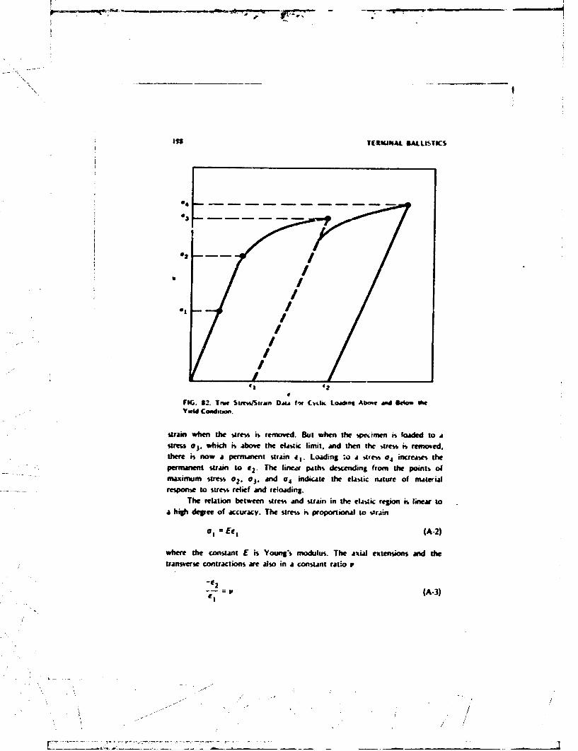
\.3
0
In1 TIFEIWUAL SLALLI$TIKS
* /
MI. 822. Tns StneWStion D.ý Im fCvtk Loadng Aticn and lkl If
strin whe the stress is removed. But whet the spftime is lode to ASM Oj, which is Abv the• t~dic limit. ai then the -Aress 6• ref ed,there is now a pe'rmnment strain el. Loading :o A WIe,% aA increases thepemaen strain to C2. The linea=r path-, dewxrding from the points of
S ..... m x i muW m s~tress O Z, 0 3 .an d 0 4 ind ic te th e elAsliC nat~ re O f R aleCFWresponse to stress relief and reloading.•
The relation between sire% and %train in the tla-Aic region ii. linear toa high• degree of accuracy. The stress is proportional to vrain
a, = Eeli (A-2)
whr th ¢.rn~t E is Youngl's modulus. The axial extensions And thetransverse contractions are also in a constant ratio r
- e 2( A 3
el-
.- /
S.. / .

AMIENDIX I99
that is ca Ponions rawo. Thes two fonstants dermine the elma.- Properties Of the mnaterti
Stre•swramn data ame dhrn an Fill 83 ftr a tool %ael 43411 m- anAmimns iloy. Thew ame obviouy wry dMimilar in mn kip.-er---' The uool t,,el has a yield point that i more than three tun
the yield point oi the Anminum alloy. lhe elatiz nmodii of the twomteriaks also nmfi-A.ny differ. The uminum alloy is wiaely used in
aircraft cns on, athouOh it has been rep-ed in many nodem aircraft
1#0
120• i.. so
I -
40
//
0 .Q DAM O O."OO6 0.C004 CLOW UI2
STRAII
FIG. 53. Tensile Teo Data (w Two Materials.
- P
"\A

bV other ium 4lo. and %aiaknle- tec4, ard titAnsum Jl"¶% The -iA ML
Ia the leemirl propertw* of the anmor ot admored v.t4slce and Aho thecore mrater ia of pruecUlei.
The tension%, e•eum forces, and comprevaon withw a body cm be
described in a waV which .appi whethet the bodo P%, solid, liquid. or sas,
Tht body is imagined to be disided mino mxan il c.h, W1p .nflni, ez.-.cibes. Forces applied to the entire body result in a "iLibutton of mouenal
force within the body that ft described appWiom.atlv by the iwwrisal
forces exaerted by each compArumen t 3n those compartmentis that ateadijacent to it. The smalk-r the Lompwrrtmets we made. i.`& line, ,s the
dewcription of the distuibutimn of mternal forces.Firsc let the compartments be cubes -ibd•med bf dteding die body by
Cartsiar. coordinate% and consider a method for lii6N the forces on ivcomp•rtment. Number the three dirzction, of the sides ol the cubes I, 2.and 3 and number the thrce differen. oi-utions of the wrface- of the
cube by the direction but is normal to the uirf.ice. Now the forces can beWlsd in a rectanllair ,1A•) w which the row% comre-,poid at the %oface on
which the force% Act &n the columns cirr"esofll to the directions of the
components. An array of these forces is shown beoIw.
Direction%Surfaces
__ 2 3
I F 1 F~ F1
2 F 21 F 22 F23
3 F, 32 F 33
The force ctmzponents Fi t. F,.. and F 3 3 are normal to the surface. Thesea:-- tensile forces if directed out of the cube. compresuve if directed into
the cube. The forces F1 2. F2 3, and F 3 1 Are parallel to tne surfare. Theeare shea forces. It can be shown that the net moment on the cubebecomes zero As the cubes are made smaller and rmaller,. ad this requires
that cerLain of the shears musz he equal
F1 2 = F 2 1, F 2 3 : F 3 2 , F 3 1 :FI 3 (A-4)
* I=
.4 '- i•; ,-

4fnE~ 201
Thess interal Comt e~ pai on the Marlace, and int order to haw a6twiraioian &ith dw macmA w.dtwmI that does not depend on theGArnWmt w fth corma~iwtnief, the vtte~s ib defined as Wh forc* per iunt
Fi, F,,tS 1 232, 4'S
for eiamnol. In the kIsa as the cw~mprnsno t bxoene ever uanaller toffeeare :ý4 &Uh1iv compm.ents -i svrei at each pumfl ct the body. Thewe arewrtact dentitsem of force, whichi. kkg the ms dew~ty, ate definted at each-m and can be uwtd to calculate the force an arny vwen finite um,.e
Thie peat vatar of the su.-% wncept #% that it makes it fejajble to arulyzeatusmnum diar utionb of inwenal force.
Scam siniplet exanwdes of wesesas way mite Jtw concept clearer. AIoft rod with a upitre cro% aso tetha t nis upended on one end &d hasa wei~va W on the oche waill Naw itemal forzes tha are directed glongthe rod. The arry of sumes comsponents will be
oil 0 0o oo0o 0o0 (A-6)
The svme *I i a, I I /WA and is an the w0"ac pervendicutar to theIong axis of the rod aWdan the direction of that axis Thi. . i tnlstrew There are no internal diem,. and the noratal force to JU othermwfama are zero.
A tunform force distribution over All ery lap plane uffaýz *fillpediace no sheirs, but thee can be forces on the taxfamues peepetodicular tothe 0"t irurfx so that the array of trsum wnmsonents will be
al0 0
0 a,, 0
0 0 *22 (A-7)
"Hydrottatic loading produce no shears but equal stesies on All wrf aces sodul
a 0 0
0 a 0
00.a (A4B)

20'.1 TERMINAt BALLISI ,CX
Suain
The deformation of a body is described by con~idnr.* 4-mo-iriwar;eras in the definition of stress. Ihe degree of deformation i. r.ci.•.ured 'iy t.-crelative elongtioe of a cube or the amount that the cube shea-ed. Thusthe ekoptions and contracions are
W29 2 2 , I-
£3 2
Nd the Jhears de
All
•a2 2 •
e23 ' 3
3
Deformation is expressed in an appropriate faim for the continuousdeformation of a body by replacing the finite quc,.ients by derivati%es. For
example,
A/2 3E
IF ax,
~~ - -"• • - - .

APPEN•I • 203
A 'hear of a 2 surface in the 1 direction has the same effect as a shear of
the 1 surface in the 2 direction, and therefore it is simplest to combine
these two proiesses so that, for example,
141 - 42 (A-10)12 \'VX2 ` xI
An array Uf the strain components has the same symmetry as the stress
Ell e12 e13
612 e22 C23
e63 623 e 33 (A-11)
"the mechanical aspects of material behavior are in tha- relation between the
components of stress and strain.
Hooke's law, which states that stress is proportional to strain, implies
that each stress component is related to the strain components in a linear
form. Thus for example,
! C1 1 11 +C 1 2e 2 2 + 1C33 3 +C 1 4E 1 2 + C1e3 6 2 3
022 C2 1ei +C2222 + C23e 3 3 +C 2 4e 12 213 +C2 6 2 3 (A-12)
etc.For al: six stresses this would require a total of 36 elastic constants
and would in general describe an anisotropic material. For an isotropic
material the symmetry conditions reduce the number of constants to two,
and the stress strain relations are the following:
om X X(ex + eyy + e,,) + 2gex•A
aY , : x(e, +ý4 + e,,)* .+ 2 ,a ,, = X te r . + e yy + e, ,) + 2 p .,
Ozxy 2Meyx(
aY 2pe.
= 2e (A-13)
2; IX
L-

204 1 ERMINAL BALLISTICS
The cnnstants p and X are called the Lamr constants. The LamW constantsare related to Young's modulus and Poisson's ratic as follows:
2i ~2.u " ' •( (A-14)
The permanent deformations of a material bring about drastic changesin the relationship between the stress and swrain. These relations aredescribed by a yield criterion that specifies the combination of stress andstrain at which the changes occur from elastic to plastic behavior anddetermines the relation between the permanent deformations and theapplied stresses.
A yield criterion is a mathematical relation between the componentsot stress that meet the following requirements that are based on empiricalobservations of the general properties of plastic deformation:
1. Permanent deformations begin when certain stress combinationsexceed critical values.
2. Yielding is not influenced by hydrostatic pressure.3. Yielding does not change the volume of the material.Yield criteria usjally use a particular resolution of the stress
components into stress deviators and mean normal stress. The mean normalstress is
a= ll + 22 0 33 (A-IS)
and the deviators are
Sll =01"$ S12 @01 2 "s
S22 z 022 " $ S13 a 013
s33 " 3 31-s $23 z 023 (A-16)
Examples of yield criteria are von Mises' and Tresca's criteria.
von Mises:
I 1, + 2 ,,). ,. +S2, +S2 ' (k.17)

APPENDIX 205
Tresca:
* [( 22 s3 )2 4k 72 ~ -S 2 2 )2 4k*2] 0 (A.18)
* ~The quantity s, which is like a pressure, eliminates the influence of pressureon the relationship to strain. The von Mises equation, for example, impliesthat sI , s 12, etc., keep the above sun' equal to k. But s may hawe anyvalue.
ENERGY OF DEFORMATION
The energy of deformation can be computed from the data of thesimple tension test performed on a bar of a metallic material, for example,the data of Fig. $1. The machine applies a force F corresponding to astress a = F/A for the areaA over which F~is applied, and the bar isstrained by # z Nil1, where At is the increase in bar length and I is theoriginal Length of the bar.
In Fig. 82 if. ais kept les than 02 - which is the yield point, andthen reduced, the bar reverses the path and goes back to 0, but if a goesso a point above o2. say to @3, and is Othei reduced, then the dashed pathis followed. The work done on ith bar cw Iie measured as JFdl since di isan w'cremerd of distance in which the ucte F acts An energy density isobtained by dimviding the work done ' dfie volume of the bar, which is At,but this is just f(FIii)(41l) ~- 'W, This obviously assumes uniformity inthe bar.) The energy density -,o the rod is geven by the area underthe am.e*/strain curve. Thu' ..,w c ...kc loading less than a2 there is no areaunder the curve and the. - ie no -wt wcrk done when the stress returns tozero and also, ws p' nent strAin. But for cyclic loading that causespermnanent susa r. e-A net work done is equal to the are indicated bythe shading anid k at energy required for the permanent strain e2.
Other si I,. tests could be conducted using compression shear orosion Instea of tension. The ivsults wre essentially the same with
Oeemin the descriptive parameters. Combinations of types of loadingcnalso be used and are consistent with fth simple tests but, of course, are
intch I sone complicated.The perforation of a very thin plate by a pointed projectile offers one
comparatively simple example of the use of a calculation of the energy of-

S.. . . .. . . .. . ..... . .
S206 TERMINAL BALLISTICS
ii 00
FIG. 34. Thomsen Assumptions for the Etimation of Plastic Work in DuctilePerforation Mode.
deformation in terminal ballistic theory. The starting assumptions are that
the plate is thin compared to the radius of the projectile, and the relation
between stress and strain is approximated by an elastic response up to a
yield stress and a constant stress for all strains thereafter (Fig. 84). This
kind of material behavior is called perfectly p/askt. The perforation of the
plate occurs by the piercing of the plate 6y the tip of the projectile
followed by the deformation of the circular sectiun of the plate of radius
equal to the projectile radius d12 so that this section ultimately foims a
cylindrical protrusion on the exit side of the plate (see Fig. 84).
Stresses and strains are moss conveniently defined for elements
determined by cylindrical coordinates. The stresses are ar, al, Oq, and the
strains are er., e, ee. It is assumed that due to the thinness of the plate
and the fact that it has been pierLed at the center, the stresses a, and a,
ae zero. The energy of deformation is estimated by calculating the work
that is done in moving and deforming the circular section into the
cylindrical protrusion. The stress oa = o. because of the assumption that
material behavior is perfectly plaszic ,nd the work on an element of the
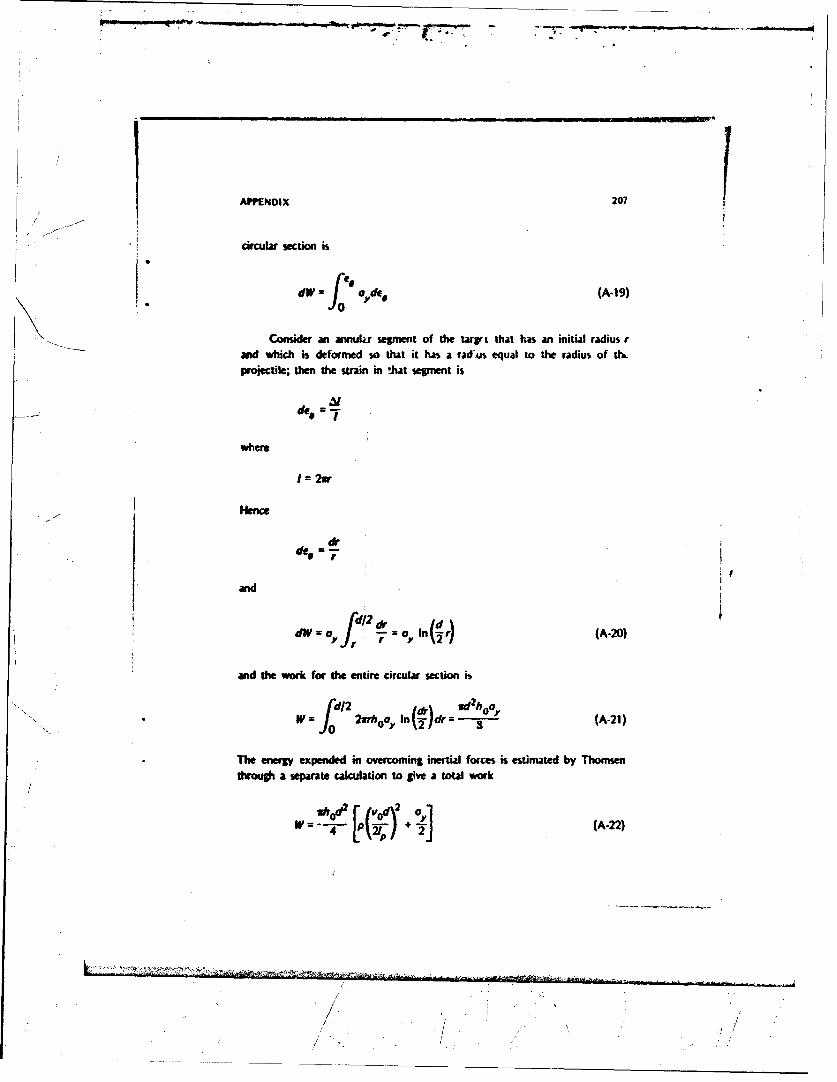
APPENDIX 207
•cicuarx setion 6
dW = f o",de. (A-19)
Consider an annulu segment of the tarvt that has an initial radius r"and which is deformed so that it has a rad.us equal to the radius of th.
projectile; then the strain in that segment is
des
where
I = 2xr
Hence
der
and
dW = I,/n(1 (A-20)
and the work for the entire circular section i
f j wdwhd1 In U)dr so(A-21)
The energy expended in overcoming inertial forces is estimated by Thomsenthrough a separate calculation to give a total work
/2'0I OA oy(-2
P .,/
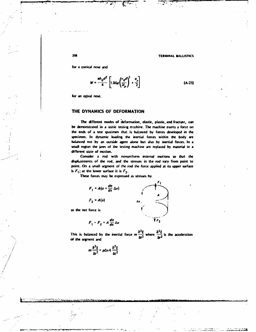
208 TERMINAL MALLISTICS
for a coni"al nose and
W = - .- .60'( 1A-23)
for an ogival nose.
THE DYNAMICS OF DEFORMATION
The different modes of deformation, elastic, plastic, and fracture, canbe demonstrated in a static testing mzchire. The machine exerts a force onthe ends of a test spacimen that is balnced by forces developed in thespecimen. In dynamic loading the inertial forces within the body arebalanced not by an outside agent alone but also by inertial forceL In asmall region the jaws of the testing machine are replaced by material in adifferent state of motion.
Consider a rod with nonuniform internal mottos so that thed-spLements of the rod, and the stresses in the rod vary from point topoint. On a small segment of the rod the force applied at its upper surfaceis FI; at the lower surface it is F2 .
These forces may be expressed as stresses by
FIdo
FI = A(o + W-x) /1
A
F2 A(o) A-
so the net force is
doV F2F, - F2 A A ;
2x
31 a2tThis is balanced by the inertial force m where -;-2 is the accelerationof the segment and
-/ ~a2f : o=
&2 U
//
II
pI W /'~ ~ ~ - - - - .. ------

s.... . -
A•-NDIX 209
In static loading the strain is measured by the elongation per unitlength. For dynamic loading the strain is the local elongation pet unit
length given by In the elastic range of behavior
S]d atS ..... o=E• E:- Young's modulus
Thus
• at2#tiXjEAAx a 2
or
a12
ax2
-his equation is satisfied by
=fxict)
where
"C .(A-24)
Hence it is a wave equation since it implies that disturbance! travel throughthe body at a constant rate, c. It further implies that the dynamics of the
rod can be worked o*t by wave propagation.Suppose again that a force F is applied to the rod, but now in order
to account for its elastic character any effects produced by F will travel atthe rate c = v .- The effect of the applied force is to shorten the rod. Itis therefore these deformations and accompanying internal stresses associated
with this contraction that spread through the rod at the speed c. Thedeforratiso- may be quantitatively measured by the contraction per unit
length, for which the symbol e will be used.
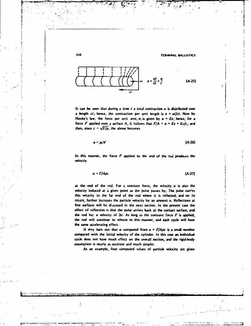
210 TERMINAL BALLISTICS
SIII 0 I • /I "I U I/
Af• €t M €
* a':e=-=-(A-25)
It can be wen that during a time t a total contraction u is distributed overa length ct; hence, the contraction per unit length is e = Ol/ct. Now byHooke's law, the force per unit area, a, is given by a = Ee; hence, for aforce F applied over a surface A, it "ollows that F/A = a Ee Eu/c, andthen, since c = Vf'1p, the above becomes
o PCV (A-26)
In this manner, the force F applied to the end of the rm produces thevelocity
u = r/Apc (A-27)
at the end of the rod. For a constant force, the velocity u is also thevelocity induced at a given point as the pulse passes by. The pulse carres
this velacity to the far end of the rod where it is reflected, and on its
return, further increases the particle velocity by an amount u. Reflections at
free surfaces will be dicussed in the next section. In the present case theeffect of reflection is that the pulse arrives back at the contact surface, and
the rod ha: a velocity of 2u. As long as the constant force F is applied.the rod will continue to vibrate in this manner, and each cycle will have
the same accelerating effect.
It may turn out that u computed from u = F/Apc is a smail numbercompared with the initial velocity of the cylinder. In this case an individual
cycle does not have much effect on the overall motion, and the rigid-body
assumption is newrly as accurate and much simpler.
As an example, four computed values of particle velocity are given

A"ENDOY 211
below for a steel cylinder of unit area subject to the indicated forces.
Force. Velocity,Ab ft/sec
1 0.0004881AW0 0.488
10,000 4M81.)00O,000 48.8
This table s&mw that ther mre only small velocities ass.ciated with forcesless than 1,0tW pounds; hoe , for many applications, an analysis along thepreceding lines is not the tnws convenient. Conwarsely. the table showvs thatlarge forces are gmerated by quite moderate particle velocities.
Stress waves in extended bodies travel at a higher rate than stesswaves in rods. This is due to the differences in the relation between stressand strain that are brought about by the proximity of the lateralboundaries of the rod, It can be shown that for an extended isotropicelastic medium there are two propagation rates of eLasti disturbances, onethat has its particle vebcity in the dkrecion of propagation and one withpartkice velocity perpendicular to the direction of propagation (transversewaves). These propagation rates can be computed by Eq. A-28 and A-29.For lorgitudinal waves
C (I #)(I- 2)(A-28)
whe re is Poisson's ratio, L~e., the ratio of strain perpendiocular to thedirection of appied stress to the strair. into the direcion of applied stres.
For transve-se waves
(A-29)
'I wieser is the torsion modulus.Elas*i stres waes in a thick barrier due to projectile knpact would
travel at the longitudinal propagation rate. The difference between the rod*value adteetne-eir o tdnlnr is as much as 15% and is
theelftnotirgnftat.Itsitui asobe borne in midthat fth rod
~-- -I ..2..~ / . j;

212 IURMINAL BALLISIK5
value 6 easkA to m umease a tho.relore most lAly to be given in rcpsrt•
on material bi-lvir.
e Wave Rftction and Tranmission
Free boundmuies and boundrk between media thit hae different- / •;-/value5s of th~e density p ai•d prpgtion rate c" w a chng inth
ppagation prcess. War, awe reflected away from the boundares. and
"these waves may be of A different type thin the incident wave. Reflected
aind transmitted disturbancev must preserve parameters. These continuity
conditions detrmine the wefficients of retlection and transmission, which
ae related to material paiam-;e-rv, by, the following-
1. The coefficient of rellection
= 2P2 (A-30)
where pg and c1 awe for the first material and p2 Ad c., we for the
second malcrail.
2-. The transmi•imn coefficient
U\ u ui P, (A-31)
It will be noted that p" is the imptrtant parameter. This quantity oc
is directly related to the change of mornotum associated with the zastic
deformation of a body. An elastic body does not change momentum byV the
change of iarticle velocity at all points but by the chanbe of particle
velocity within an expanding region. Thi, ajcount% for the dependence of
"stress on velokcity rather thin kLek-klration. it is the factoi c that converts
pc into change of momentum Ly aLcounting for the expansion of theregion.
When p2 cz2 of ihc second material is small or zero, the particle
velocity doubles bft;aus tht. in:idril particle velocity and the reflected
"particle velocity ate equal. The material is also at zero stre% so that the
part of the matrial covered by both the incident and reflected waie is
-T_\

- f
-AElMX 213
Smoving at twice the incident patide Velocity aNd Wit t Stams It islieuently in local rid body motion. Thus, reflectio at a boundary
* pro6es ugiidbody - aL Pubes wil continue to ravel thrsuh thea:ae\ medim produckq rnid body motion until h presurwe inde theamedium is reduced.
Wave ftoptSlon for Pafb Abo the Yield Poft
The sUrees in a mnuial loaded above the yield point ae of theform
S11 +S S12 S13
$12 s22 ÷s $ s23
S13 $23 S33 +S
S_ These stresses can be resolved into an elastic stress &W an hqiom presu•eI/
1 l12 013
012 0 2 2 *P 023
013 023 *23 *P
f(r widch the elastic stress is the su that is apprc at for the boundarytonditions and the type of loading. For example, if the material is loadedon a plane surface, and the material is of weat lateral extent, en mthe stateof s-ress would be the eastk sues tat holds for mro elastic stains in thedirections normx to the direction of loading aid at the yield point of the
materia peus a hydrostatic pressure ta accounts for th remainder of theapplied stess. The relations betwee strm and stain are then thefollowing:
033 e K(e',)
a12 = 023 =O (A-32)
\- /

214 TERMINAL SALLIoTICS
The eUlia, and plailic component% ol ihe-c ereW-'am relations,. oprct
dliiinct type% of behavior each with A different modulu%, and it hab been
proposed that the propapition #A itcf-% at the yield point and Areieýtwoe the yield point simulan j rJy prop4ate .at differit ralme Thk
menm that the wave shape will be determined bty ptupptxion rate% that me
different for we% k1 at the yield point and -Art& leech aow the yield
II a cunqtnt bad a, ii applied IOut i6 abve ft yield ire% u thena wave with Lonunt itre a, will travel at the ela*Aic wave velocity and a
sefond wave with -Are-i a, hil! travel at a Jowet rate so that the wave
would have the changng wave dupe hllu%*rjtcd in Fig. 85.
Sl PLASTIC WAVE
ELASTIC VAVE
TIME
FIG. 85. The PropAatlon oI ELasia and FraukWave in m Mjgeital Loaded Abow tie Yield
S... .... .. •rsie .
\~
1*

AVEftO4X 2iOs
The elassic stress propagatft at the rate
L E(l - aP)(-3of pQ.I - (A.33)
and die plastic wave propagate% at the rate
(A.34)
Atrms and strain ft nonlinear an utbe described by nonlinear mtosThese methods have been developed for ordinary fluids, and cnbe
* ~borrowed for the prediction of the fluid-like behavior of mietals above Ohe
yiel point.n.T ew
Wave Propagation an Fluids
Changes of density and pressures are the counterparts for fMuids ofstrains andl stresses in elastic solids. The relation between the pressuat 4Mddenisity is in general nonlinear and sometimes significantly nonlnea. Forexample. the adiabatic gas law
P =nRTp1 (A-35)
hods for many gases when changes of pressure are applied sufficientlyrapidly to prevent the gas from coming to thermal equilibrium with itssurroundings or within an insulated container. The sir4*l linear methods ofelasti wave ropagation wre not appropriate for many fluids (in particularpesf) because the relation between streis and gtrain is nonlinear.
In order to see how the nonlinearity affects propagation, considier aplaine watv propiagating through a fluid Ohat has a norlinear relation
a between pressure and density. It is asssimred that the propagation rate is c'.The principtes of the conservation of momentum and mass can be used to

216 TERMINAL BALLISTICS
show how variations in P, p, and u me related to the prnfpaption rate. This
is done bI, exmining A uhin Layer of the pline wzve th4t changes locationso that it moves with the wave form. Conservation of mass anid momentum
is computed for this layer by determining the flow of mass and momentuminto ard out of the layei. The'e flows depend on the combined effect of
the motion due to the propa:•pun of the wave form and the local motion
of the material.
In Fig. 86 the wave is shown propagating to the [-!ft at a velocity c'.
This means that variation- in pressure, densitr, and velocities of the materialcan be described by the relations
U = u(X - C'1) P = P(X - 6') P = P(A - 6') (A-36)
where x is a coord'nate in a fixed reference system. Oi0 the right boundary
of the layer the density is p. the velocity of the material is u, and thepressure is P. On the left side of the layer the density is p + Ap, thema.terial velocity is u + Au. ard the pr.,%ute is p + 4p. The rate at which
4
LI
OI$TANCE
FIG. 96. Iutse Traveling 7hrousl• a Fluid With Sufficient intensityto Display Nonlinear Effects.
...

APPENDIX 217
any parameter is carried past the boundaries of the layers are c' - u - Au
for the right boundary and c' - u for the left boundary.
Conservation of mass requires that the flow of density in'o the layer
must be balanced by the flow out of the laycr.
(c' - u -tu)(p +ap) (c' -u)p
Ic' - u)Ap = pAu
Conservation of momentum requires that difference in the flow of the
density times the material velocity must be equal to the pressure difference
across the two surfaces.
(c' - v - nu)(P, +)(U + AU) - (c' - uJ)PU = bp
The expression for the conservation of mass can be used to change
the form of this equation
(c' - u)p (u + u) -(cW- u)pu =Ap
(c' - u)pAu 4 A
The above equations for conservation of momentum and mass can becombined and solved for c' - u
(c' - UP L• (A-37)
S ap (A-38)
This quantity (c' - u) is the velocity of the propagation of disturbanceswith respect to the material, since the velocity of the material is removed
from the velocity of ,rop.agtion observed with respect to fixed coordinates.
Thus the velocity of propagation of disturbances with respect to the
material is
C (,{v) (A-39)
Ja

2IS TERMINAL BALLISTICS
O.N-I1Y D.STANCF
FPb.. $7. Adiabati,. Lf4uation oflatle ,Aed Ih Rclaticm it, lkave Ptrvp•.fatwn.
Ihe dependenLe of the propagation rate t on the density p ha. veryimportant conequcnc•.. Consider d tluid in *hi(h precure and density are
related as %huwn in Fig. 87 for an adiabatli pocess. Since the propagationrate c is given bý f = %p-!op. the presure p,4 is instantaneouslypropagating at t, and presure Ps at c# and at ,onfe later time the point
A will tend to overtake the pui.- 8 .and liiu% ,teepen the pukle. Thisprocess eventualih, tend% to create a discontinu!•t. I hus. small disturbancespreserve the ,,hap" of a pulse. but Larger disturh..nces tend to Lause
sep-fronted shape.
SHOCKS
Small-amplitude disturbance. and finite disturbances during the buildupto steep leading edge%. can be described bh thcrnmodnamicallv reversible
processc, because the gradients of tempcnalure and helocity are s4o smallthat heat conduction and %i%.ositv are notl impcoluant rhcnomnna. This is
not true when the pulse tiake on extrem.l' steep hfrnts. Thus .Whoks. the
final result of the changes in puke shjip.. are more cumplic•ated phsical
phenomena because disipatise procew.- ate ,ignitucjat Fortunately, thelabor involved in analy-ing the behavior oh 4hodkm, i% reduced by using theapproximately disc.ntinuous nature o( the disturhances. A set ofconclusions about the full-gtown shock can be derived without going
through the complete anal'si% of the more .omicatvd processes that lead
up to it.

APUCNDIX 219
A wery aO ipt change in pressure, density, and velocity is assumed to
be travelingq trou•h a medium. The values of pressure, density, and velocity
that are compatible with such a stzte are determined by applying
conservatiot, of mass and momentum to a layer that includes the abrupt
changes in these quantities. The conditions are illustrate. ciwiim-tically in
Fig. S8, which is similar to Fig. 86 for the continuous changes of pressure,
density, and material velocity. The shock travels at velocity U and the fluid
ahead of the shock moves at velocity u 0 and behind the shock at velocity
u. The pressure and densides are p 0 , p0 ahead of the shock and p, p
behind the shock. Mass and momenLum flow into the shock at the velocity
U - u 0 and out of the shock at U - u. Mass flow into the shock front is
pu(U - uo) units per second, and mass flow out is p(U - u) units per
second. To conserve mass
P0 W - u) = p(u - u) (A-40)
The flow of mo.aentum into the shock front is po(U - uo)u units per
second and the flow out is p(U - u)u. The difference in these rates ofchange of momentum must be equal to the pressure difference
, 0o(U - u)(U - uo) p - Po (A-41)
ppu,
PO~ 0 UO
0ISTANCE
FIG. S11. Schematic Representation of "Jump" Changes of Variables at aShock.

220 TERMINAL BALLISTICS
From these equations U and u may be calculated as
U F-'O 0)-(A-42)
amd
U k -Po U (A43)
To determine the numerical value of the shock propagation rate for a
particular material we need an independent relation between the pressure
and the density, such as the adiabatic gas law. The adiabatic gas law cannotbe used because it is based on the assumption that there ate no dissipative
processes invol-.-o. An appropriate relation can be found by applyingconservation of energy to the propagation of .•, ?brupt changes in pressure,
material velocity, and density.
pu - P 0 - E0 2 (A-44)
The differences in the rate of change of energy at the boundaries ofthe layer are equated to the rate of doing work,
PU- pOu 0 + (U - UO) [E - Eu 2
where E and F are the internal energie-,, usually u 0 0, and theseequations can also be rearranged to 'have the form
p(U - u) = poU
P - Po pIu
E- E0 2 (A-45)

.- "APPNDIX 221
Ihe ,,on for rearranging the third equation Is that if the equationof state is known, the internal eneries cAn be calculte• and the thirdequation provides pairs of pressures and delsities that are compatible acrossa shock. This is called the Rankine-ful;Diot relation.
Shock Reflection and Trammission
The reflection of stress waves in materials with linear shess/strair:relations or in fluids with very low amplitude disturbances Is given by the
, (A-46)
"For shocks the use :f the quantities c in the above formula is usually notsufficiently accurate to describe reflcction and transmission except as an
/ aplroximation.Suppoe the arrival of a shock at a material boundary produces a
shock in both materials. The shock in the first material is not convenientlyconsidercd as the superposition of distinct reflected and incidentcomponents, but In order to indicate the components analogous to the sumof the reflected and incident pulses the subscript I + r will be used.
The shock relations in the first mateyial are
., +,(u u) M P-,(u,.,.+ uP) (A47)
Po. - pI = 'Pu 14 + u,)(u, - uk,) (A-48)
E,., - E, = 2P+ +P (A-49)
The last equation leads to the reflection Hugoniot
I•-(A-0)
P, AP-" PI

4. We' .7* 1 .- . v--~-
I .... -
222 TERMINAL BALLISTICS
Equation A,49 is similar to the i--;,nce relationship between stress andparticle velocity, but there is no simple linear relationship. By combiningEq. A-47 and A-48 the difference of particle velocities is found to be
(ASi
This equation and the reflection Hugoniot determine a relationship between
U1 - uir and p. This and similar data for the incident shock are illustratedhi Fig. 89.
In addition to the reflection curve, the cuwves for the directpropagation in mAnium I and the direct propagation in medium II are alsoshown. These curves are derived from the same kind of arguments as 'hosefor the shock relations for direct propagation in these media. Theintersection of the direct curve for medium II and the reflection curve formedium II is the equivalent of the equality
Of I (UI + U) s P2C2Ut (A-52)
From the data at this point of intersection the characteristics of the shockin both media can be obtained.
MEDIUM II
MEDIUM I
PARTICLE VELOCITY.I
FIG. 39. Hugonlot Dau for Shock Reflections.

APPENDIX 223
SIThe preceding discussion is an introduction to the basic concepts of* Ithe dynamic response of metals to impact. These concepts have been
developed for the simple configurations of rods and infinitely extendedbodies, since these are about the only examples in which the essentialfeatures of the dynamic responses can be illustrated in terms of elementaryanalytical methods. It is feasible *o extend these ideas to more generalconfigurations by the use of numerical methods in the solution of
/ differential equations that govern conservation of mass, momentum, and• ,energy and the description of material behavior for a continuous medium.
This was discussed in the section on Warhead Terminal Ballistics.The ideas developed thus far can be used to estimate certain stress
L conditions that are important in terminal ballistics and to help interpretempirical data.
MAXIMUM STRESS IN IMPACT
In the discussion of th-. causes of instabilities of proiectiles penetratingearth media it was pointed out that the initial stresses on the projectile arehigh during the period of minimum flow in which the stresses aredistributed through the medium. The pressure in this period was estimatedby
p 0 pW (A-53)
The meaning of this formula has been demonmtrated in the preceding, andmethods for determining u have been developed. Strictly speaking thesemethods apply to a flat-ended projectile and therefore overestimate thevalues for commone projectiles. The more pointed the projectile, the morequickly will flow relieve the stress to a value approaching
I,.2
(A.54)
where f accounts for the variation of 6ie dynamic pressure over the surfaceof the projectile.
I * --
7 .-- 7.,

224 TERMINAL UALLISTICS
NATURAL TIME INTERVALS FOR LARGECHANGES OF DYNAMIC STATE
The fact that stresses propagate at a constant value makes the transittime of waves through a plate and back a natural time interval #or changesof dynanic state. This transit time is the minimum time interval in which aplate is identical in response to an extended medium. For Impact velocitiesthat generate Wesses in the elastic region of material behavior the elasticpart of the two wave systems may be important, but in general theestimate of the time interval would be based on plastic wave propagation.
THE INTERPRETATION OF DATA ANDTHEORIES ON RESISTING FORCE
The yield behavior of metals pruvides a specific phenonenologicalbasis for the in:erpretation of the Poncelet form of penetration resistanceforces. The veiocity-independent term is naturally related to the yieldstrength or an empirical measurement like hardness. The velocity-dependentter-n Is related to internal effects expressible as a dynamic pressure. Figure90 shows data on the penetration of long projectiles into thick barriers.These data have been fitted by the solution to Poncelet's penetrationequation. The correlation of experimental data to theory demonstrates the,general applicability of the Poncelet form of the resisting force. This "tinof penetration resistancv has been sugested many times. The ou?, Ain&limitation is a lack of information on the variation of the resistifi formswith variation in plate thickness.
Reference 45 gives an example of the inclusion of a measure ofstrength in the resistirg force. Assuming a resisting force of the form
F u 2 (A-55)

1.2.
so -. .kS C
I2 001 -5-
/pp In Jý JA 56
ff -- Tt
• • 0.4"'10
,0.2
00 0.2 0.4 0.6 0.6 1.0 1.2 1.4 1,.6
FIG. 90. Relative Penetrationt Plottedl Ag*Inst Impact Velocityr.
' we obtain a formula for penetration that is of the form
T='•) + + m lp u 2 '•
+ 2 ____ /
\)
/
-\"

226 TERMINAL BALLISTICS
CALCULATION OF STRZESS INTENSITIES FOR SWALLING
The propagation of stress can result in the failure of the barrier aheaduf the projectile as the stress waves generated by impact reflect from thefree surface and interact with the latter parts of the incident wave. This isillustraed in Fig. 91, which shows different stages in the propagation andreflection of a shock from a free surface. If the incident Wakve has theshape shown at the top, it will reflect as atensile wave, as is shown in thenext stage, and as it Combines witn the incident wave it will eventuallydevelop a net tensile stress in excess of the yield strength of the materialaind cause fracture.
COMPRESSIVE I
11 r~A~PL~A LSE
TINSI LE
1COMPRESSIVEJ' ARV T FE SURFACE
TENISILE
COMRESIVI REFLECTION ANO SPALUING
TENSILE * ALN
FIG. 91. Shock Reflection and SpaiwnU.
........
7 1 ý77 ¶771-101P

K 227
Subject Index
Awoftnamvcs of a proecdWl. 41 Chap"ManIouSt hypoehakees 110Seownlis equaion 44 Composdtkis ot propoilants, 16-17co o &j& ef g43 Cylinde exapseim aetM 124div, of vWscosity. 45
Wft. bag, and yawlag ffmwmma, 45 Defab of ibs prokcllh Army allurlon,
gooady flow. 42 71Analog he". waoa n m 9 Defe of dos pmoaft, Navy arim!^~a
71galibik Emt,. Thwu'mm 4quaton 3.5I DeflwAmao I111
Sesuoul's euat~on 44 baclon anad rkcochet 57in etrior balsht~cs, 4 DeflectIon sf s"m wphom from anakummis #aped-cbarg collpe 133 putes% 9im emoinal ballitics of warhuads, 166 Detomtlon, 103, 111, 113 L
Slack powderapicto of ock vase theorV. 105rCheomost md *lbertmed amd of cormwevation of nsawy, 107
burnkng 14 Concarwatlon of OLUNs 106compos~tion. 14 commrvathn of mometm 106
aimdeg.,Mlon mvae velocity. 107fa-aone procemes, 152 whyodyoan5 theory 105"inW-4n" peocmew% 149 put~cbe vetlog~y 0peak evepromemi as a function of Dra on proiscile
dbstance 153 from aweodymamk forces,Peak overpresmierlae to Mack in pentation of so00s6 59
mimbw.,152 d~gas a function of Mach o nube forprenoo beh ind OWh 6 bok,14 pro*ect~s, soscalI&g 155 drag ma funcimonfma* naerfo
diock strngh 152 wphorm% 51TNT equivamec of maI wtploswvs, Dwcike mechanica beavIor of mAterahW
157 73arsismchanica ehobvlw of matelsd Dylcvs of deformatdon. 203
73 DynamIcs of deformAtion of a rod uwaer$wow& w~amaaoool PseMW*bAnco consat form, 209
cwv fr.3SElasti bdiavlo of madateal. 72
Calculations for refernic explorslo, 1S5 Enegy of deformatoon, 205
N"7,
A7

225 TEEMMAL MAULSTICS
Energy of deformation. Thossen Gunscalculation, 20S-207 Igdtion, 13
Energy required for perforation, 36igm:loa primea. 143.11w equatiots, 57 hnteriur ballistics. 11Thomsns. equation, 87 rplatburning ram, 22
Equation of sate propellant chemistry anddetonation products, 109 lthsrwodyftAmics, 14Kige1wprsky-Wison, 109 propelant compositions far, 14
rattsod,109Gurney constants, 122van der Waas, 109 Gurney fonrwu" 120. 122
Wilkins, 109Expansion of a warhead case, 119 Higb-etaiegth barrers, 71Explosivs mechanical behavior, 72
aluminized explosives, 1I mecahanism of penetration, 73composition 3. 117 MUPonos curve, 108-110cycictols, 117 Hugoniol curve. distinguishing beten"HMX. 116 OefLagation and detonation. I I1pentolites, 117 Hugoaniot relation, 105PETN, 116mDx, 16 Impact by coaesnoed rods, 165teryl, 117 Impact by cone-oasd rods, UrOldimsil'TNT, I11S equation, 166
Explosives, types of, 112 M~ac of rods Against plasess, ISmixtures. 117 etaric behavior. 160primary, I U elasopLstlc bavWer 163Miconijary, 11 esastopiasti behavior of projectile and
Exterior ballistics of projectiles. 37 barrier. 167dynamics of a projectile ini free flight. interimr ballistics, goes, 11
37 Interial ballisticsprojectile trajectories, 38 booic equations, 29projectile trajectories in vacuum. 39 Lagrangs correction, 27project to trajectories with air of warheads. 101
resistance, 41 summery. 36Exterior ballistics of warhead fragmen ts, warhead main phenanwia, l01
142"eation. 146 Laange correction in calculating prewuraerodynamic heating, 144 at bane of projectile, 27shape factors for fragment shapes, 143 Lagrange correct* n in warhead knternal
ballistics, 120. 123Fragmentation of a Uarget in impact, 182 Lamj constants, 204Fragmentation at a toget in impact, Lift force on a projectile from
metallurgy study, 123 aerodnamic forces, 4FragmentatkAc of warheads, 125 Lift force on a projectile penetrating soils,
"brittle- and "ductile" behavior of the 70material of the warhead use, 131
L&4n pressure vesse theory, 127 Maximuom stress in Impact, 223Mohr circle to repretselt streesm 129 Mechanical properties of materlals 19"
Fragment projection, 11I3 etask limit, 197
97S

SUBJECT INDEX in9
Lamed constants, 204 Penetration resistance for Vaiousstress'utrain data, 196 materials, S6
Dyoungys mojlubs, 198 Penesraticno theory, Euier-Iabkisuo 52t tarpenetration tiecory, Poncelcs, 53
Naturaltim inervls or aw han" 1 peforation, role of shear fractures, M8*dynamic state, 224 Pioenlso's law. 24
Nomenclatlur list, 4 POWsAMet form Of COlS" forc, relat00o0to yield behavlor of metals. 224
Pentetration PoncAtet resisting force eaveuea as aby Chunky trapnenu, 177 drag coefficient, 60affect of shattering of piroectili, 174 Presaure-dtaance curvehydrodynamic theory. 169 far a 3.7-inch antiaircaft gun, 14
Pimetration data for a con"ca enoded for different forms of pripellant, 34
Penetration equations location of maxima Meath*e to
fo: :apd fr : fo eketar bu3En yLt, Aw
theory. 171 Progectile acceleration after burning 32
Poncelet form for calculations for two Propellanit burning ratetsoll types, 63 cylindrical grain, 24
Sandia. 62 amuttubidiar pci,, 27Pueneration into soils, Ss taotllar grain. 26
deceleratirm record for a blunt Propellantsprojectile 10 sandy soil. 67 dept-siave powder. 26
deceleration record for pointed muftitlubulat praim 27proiecluie In sandy soil, 65 neutral powder, 27
proiectile Instability. 66i provessre powder, 27projectile instability. effect of
lathomopnetitif, 67 Resal eqution, 19, 120sro~ectite instability, unstable fesaw's equation ii, warhead IANtraW
stable tce forces. 59 Residua veoiy. Ocht formula 95
Pl~~wntion "Wharitsms Resisting force, eainbewe oAbrittle penetration, 74 farm and yield behavior ef oetalsductile pentetratIoms 74 224fragmnentiro,g 76pls.&m... 74 Scabbing. 75radia! fraclure. 74 Shaped charge jet, formula for penetration
*Penetration of a barrier Loy A derforming from elementary thoryV 171projectile, anarrals by continuous Shaped chiaroesmechsanics, 114 can".al 133
P~atlon of a barlm W.Inversion of a rod pnrhlrizaulrnt an Performance. 13SIN a eseady-state procas. 169 geooetric relationships in liner,
Penetration performance of real lets, 175 colapse, 137Pent"ation resistance, constants fore three linear. 134
Wll, 62 steps in the formation of a let, 134

230 TERMINAL BALLISTICS
Shocks, 215 Terminal ballilics of warheads. impact bl
Shocks. application of consetation laws. material from 1he warhead case.
219 159
Shock waves ssammwy. 1 b6
Hugonuot equation, 222 Trajectories of projectiles with air
Wlick velocit7 equation, 220 resistance. 41
reflection And transmisson. 221%s-locity equatioip. 220 Velocity of wArtead cs expansion. 123
SpailinS, 75 Veille's law, 24
calculation of stress inlerfmtt to cAuseWpalling. 226 Warhead ballis.ics. 97
in fragmentation proC•sfrt, Warhead eL. or balhistics and blast, 141
Strain, 202 WarheaJ exterior ballistics and blast,
Stiress, 200 summary. 157
S~res wave ptopartion above the VievJ Wa.heads. detonation of, 11n
point. 213 Warheads, fuze and expVow train, 102
Stes wave reflection am transmssiot. Wave ptopatron in fluids, 215
212 application of ;o~rivation laws, 217vrIocit) of propagation. 217
Targets. ecamphcn of. S3Tern.inal ballistics of projeLtiles, 53 Yaw equation for A proiectile peneltati *9
application of convseration laws, 76 soils. 69
summazs. 96 Yawin' .7soment on a proje•tile from
Terimninl ballistics of singe I ra•ent ae.odv.umic forces. 46
systems, 91
W 974 Is 716) 1500 l
-77