seismic retrofitting of operational nuclear facility with ... · pdf fileseismic retrofitting...
TRANSCRIPT

The Indian Concrete Journal March 201548
POINT OF VIEW POINT OF VIEW
Seismic retrofitting of operational nuclear facility with limited radioactive inventory
R. Sharma, S.K. Saini and N.S. Gabhane
Accelerators are devices that accelerate charged particles like protons, deuterons, alpha particles and heavy ions to desired kinetic energies. Electromagnetic radiation emitted by a moving charged particle can deliver lethal doses of radiation in case of accidental entry to interlocked beam areas. An effective dose rate of more than 1 mSv/hr at 30 cm distance from radiation source (after accelerator operations) is expected as a result of activation of structures or components due to operation of Superconducting cyclotron (SCC). Hence, systems and components of structure responsible for controlled operation of cyclotron calls for design safety review. On the basis of radiation hazard, SCC facility is classified as Class III type facility w.r.t. AERB guidelines and required to be seismically qualified in compliance with AERB/SS/CSE-1 to meet seismic demand as per IAEA-TECDOC-1347 and IS 1893 (part 4)-2005. A three-dimensional FEM model consisting of beam and plate elements is developed to simulate actual behavior of structure. Re-evaluation is carried out using linear dynamic analysis by Response spectrum method considering the ductility and damping factors given in TECDOC-1347. Based on seismic re-evaluation, requirements for safety upgrades were identified to meet the recommended seismic demand without major operational shutdown. Capacity of post retrofitted structure is checked and confirmed by performing 3-D non-linear push over analysis. This paper presents the details adopted for seismic retrofitting of SCC facility to meet the revised demand.
Superconducting cyclotron (SCC) at Variable Energy Cyclotron Centre (VECC), Kolkata, is the most advanced accelerator ever constructed in India and is only the sixth such accelerator in the world. It is a class of particle accelerator used for accelerating charged particles to very high speed and is vital for frontline basic and applied research in nuclear sciences. Operation of SCC is capable of activation of structures, systems or components or ionization of air resulting in generation of an effective dose rate of more than 1 mSv/hr at 30 cm distance from radiation source (after accelerator operations). Based on above radiation hazard consideration, SCC is classified as nuclear facility with limited radioactive inventory, having potential to produce an accidental dose more than three times the occupational annual dose limit to the whole body in any incident and may be capable of delivering lethal doses of radiation in case of accidental entry to interlocked beam areas [6].
BACKGROUND
Construction of SCC building was completed in year 2002 and structural design was carried out during the year 1997-98 as conventional structure as per then prevailing codes as there were no clear guidelines available on radiological safety requirements and classification of cyclotron facility. Subsequently, there were substantial changes in national and international guideline and codal requirement for design of such facilities. Being a safety

The Indian Concrete Journal March 2015 49
POINT OF VIEW
related facility, during review for operational clearance in year 2007, it was decided to check the seismic safety of structure in compliance with AERB/SS/CSE-1 and IAEA-TECDOC-1347 applicable to Nuclear Facilities other than NPPs (NFOP) with limited radioactive inventory and if required, upgrade the structure to qualify as per current standards.
OUTLINE OF FACILITY
From radiation shielding and operational support requirement, 3-storeyed reinforced concrete (RCC) structure with overall plan dimension 56.5 x 41.63
m consists of 2 blocks: i) Main vault and cave area ii) Surrounding structure
Main vault having internal plan size 17.25 m x 11m with 3.5 m thick RCC walls for radiation shielding is located centrally and attached to three experimental caves, surrounding critical facilities like Hot store, LCW (low conductivity water) room, control room, health physics laboratories, external beam injection system and related sub systems. High bay area (HBA) above main vault and cave-1 with floor height of 16.32m is provided with EOT crane.

The Indian Concrete Journal March 201550
POINT OF VIEW POINT OF VIEW
Surrounding structure consists of moment resisting frame and is connected to vault walls through neoprene pad resting on corbel projecting out from shielding wall. Entire structure rest on bored cast in-situ pile foundation with pile length 25 m from existing ground level. Ground floor plan and vertical section of SCC building is shown in Figures 1 and 2 respectively.
SEISMIC RE-EVALUATION
Seismic re-evaluation of existing structure requires selection of new design input, identification of revised performance objectives, rigorous analysis and design of structural system for assessment of performance, capacity evaluation of existing structural members and their comparison with revised demand to identify the members requiring retrofitting.
Mathematical model
For check analysis, the structure is simulated by a detailed three-dimensional finite element model consisting of beams and thick plate elements, incorporating as-built material properties, connectivity between relatively flexible surrounding structure with rigid vault, beam-column junction as per the actual detailing, eccentric beam-column joint in High bay area, slab-diaphragm action and soil-structure interaction effects using impedance function approach.
As-built material strength is arrived from statistical analysis of available cube test, steel test results in accordance with IS 456:2000 and material strength thus arrived is further examined by core test and non-destructive tests such as Schmidt Hammer test, Ultrasonic pulse velocity test, carbonation test, etc.

The Indian Concrete Journal March 2015 51
POINT OF VIEW
Performance objective
SCC facility is classified under safety class 3, seismic category 2 as per AERB/SS/CSE-1 and SCC vault to be designed for Design Class 2 (i.e. capability of structure to support safety related components, equipment and systems to be maintained) and surrounding structure for Design Class 3. Based on above, structure and its components are required to perform following functions:
Functionality of SCC shall be maintained in event of design basis ground basis ground motion and external events.
Vault area of SCC requires preventing escape of radiation beyond limit prescribed for normal operation and mitigating those accident conditions under long period earthquake.
Surrounding structure required to maintain non-collapse condition by allowing for inelastic behaviour during reference ground motion [2].
Further, building is categorized as Category–3 structure as per IS: 1893 (part 4)-2005 whose failure although expensive but doesn’t lead to serious hazard within the plant complex [7].
Analysis
Seismic analysis is performed by linear dynamic response spectrum approach. Critical of the two seismic input
•
•
•
i.e. IAEA-TECDOC-1347 and IS 1893(part-4):2005 as shown in Figure 3 is used for design and qualification. Simultaneous seismic excitation in 3 orthogonal directions is considered and their combined effect is taken by using Newmark rule in 100:40:40 proportions. Acceleration spectrum for vertical motion is taken as two-third of the design horizontal acceleration spectrum. Missing mass correction is applied for mass beyond cut-off modes, thus ensuring 100% mass participation in response spectrum analysis. Accidental torsion is considered in analysis to account for torsional moments coming from un-modeled stiffness or mass eccentricity.
Structure is analyzed for the basic loads (i.e. Dead load, Imposed load, Crane load, Earthquake load) and load combinations as per Table 18 of IS 456:2000 and clause 6.3.1.2 of IS: 1893 (part 1) for limit state of strength and serviceability. As base shear in case of IS: 1893 was less than that of Tecdoc-1347 and within dominant modes, Tecdoc spectrum was giving higher response, Tecdoc-1347 has been used as basis for seismic up-gradation.
Check for limit state of serviceability
Based on results obtained from above analysis, performance of existing structure was checked for various limit states.
Maximum deflection of structure found to be 100.7 mm in N-S direction & 146.6 mm in E-W direction, which is much higher than the permissible limit of 34.44 mm.
Adequacy of Separation Gap - Adequacy of existing Separation gap between vault and surrounding structure is checked taking into account the shear stiffness of rubber support. Maximum forces transmitted to rubber pad from supporting structure found to be
Max. Compression, ‘P’ = 98.92 kN
Max. Shear force, ‘Vx-x’ = 94.325 kN
Max. Shear force, ‘Vz-z’ = 67.46 kN
•
•

The Indian Concrete Journal March 201552
POINT OF VIEW POINT OF VIEW
Properties of neoprene rubber bearing pad [12]
Shear modulus of rubber, ‘G’ = 8.26 kg/cm2Young’s modulus of rubber, ‘E’ = 33.13 kg/cm2Bulk modulus of rubber, ‘B’ = 11111.11 kg/cm2
Check for compression
Size of rubber pad (l*b*h) = 47.5*25*2.5 cm thickArea ratio of rubber, ‘Ar’ = Load carrying area / Lateral expansion area = l*b / [2h*(l+b)] = 3.281/Kc = h/A*[1/{E*(1+2*α*Ar²)}+ 1/B] = 0.0045(where α=0.64)Stiffness of rubber in compression, ‘Kc’ = 222638 kg/cmActual Vertical deflection = P/Kc = 0.444 mmAllowable Vertical deflection = 0.2*rubber thickness = 5 mm Actual comp. stress = P / (l*b) = 8.33 kg/cm2Allowable comp. stress = 8 kg/cm2
Check for shear
Shear stiffness of rubber, ‘Ks’= G*A/h = 3923.5 kg/cm Actual Shear deflection = V/Ks = 24 mmAllowable Shear deflection = 0.4*rubber thickness = 10 mm Actual Shear stress = 94.325*100 / (47.5*2.5) = 79.43 kg/cm2 Allowable Shear stress = 3 kg/cm2
Thus, rubber bearing pad is fully capable of transmitting compression load but will not be able to transmit shear forces to support below. Although rubber bearing pad is more like a roller support as per above calculations but lateral deflection is very much on the higher side and therefore, 25 mm width of Separation gap existing between vault wall and surrounding structure is insufficient as per clause 7.11.3 of IS 1893:2002 (part 2) to avoid pounding during earthquake.
Adequacy strength of non-structural members
Unreinforced masonry (URM) infill walls are checked for out-of-plane stresses due to lateral seismic loads. Considering wall panel as simply supported on all edges,
Natural frequency in Hz, ‘f’ = λ² / (2лL²) * [Et³/{12γ(1-μ²)}]1/2
where, λ² = л²[1+(L/H)²] – for simply supported panelL, H, t = length, height and thickness of wall panelE = modulus of elasticity of wall panel materialγ = mass per unit area of wall panelμ = Poisson’s ratio
Frequency ratio of wall to structure found to be quite high. Therefore, wall will behave rigidly and seismic acceleration for its design can be taken same as that of structure. Bending moment and shear in laterally loaded wall panel is then calculated as per IS 1905. Actual flexural tensile stresses in few wall panels found to be more than allowable one.
Adequacy strength of structural members
Member’s strength was checked for critical forces obtained from check analysis. Number of columns found to be inadequate either in section or reinforcement under seismic loads.
Since structure could not meet strength and serviceability criteria under revised requirement, it needed seismic up-gradation w. r. t. seismic safety.
RETROFIT STRATEGY
Selection of an appropriate retrofitting technique requires identification of constraints in retrofitting, study of constructability and operational disruption during retrofitting, assessment of permanent impact on occupancy, aesthetics, economic feasibility, etc. It requires modification in original model taking into account identified constraints and rigorous analysis, design involving a number of trials. Trial model which satisfies identified constraints, strength and serviceability criteria under revised requirement represents final model of retrofitted structure.
Detail survey of building is carried out and Floor-wise plan, elevations are prepared to identify the constraints in retrofitting.

The Indian Concrete Journal March 2015 53
POINT OF VIEW
Comparison of existing strength of member with respect to demand
Member’s strength was compared for critical forces obtained from final analysis. Floor plans of members found to be inadequate either in section or reinforcement under seismic loads were prepared for identification and assessment of additional strength requirement of members.
Retrofitting scheme
Plant being operational, mixed retrofitting approach at both global and local level is adopted to meet the present seismic demand without major operational shutdown.
External RCC columns at upper floors are increased in size by jacketing to column section existing at ground floor (refer Figure 4) and thereby, work can be done from outside the building with minimum interruption of internal functions, inconvenience to user and also existing architectural features have been maintained.
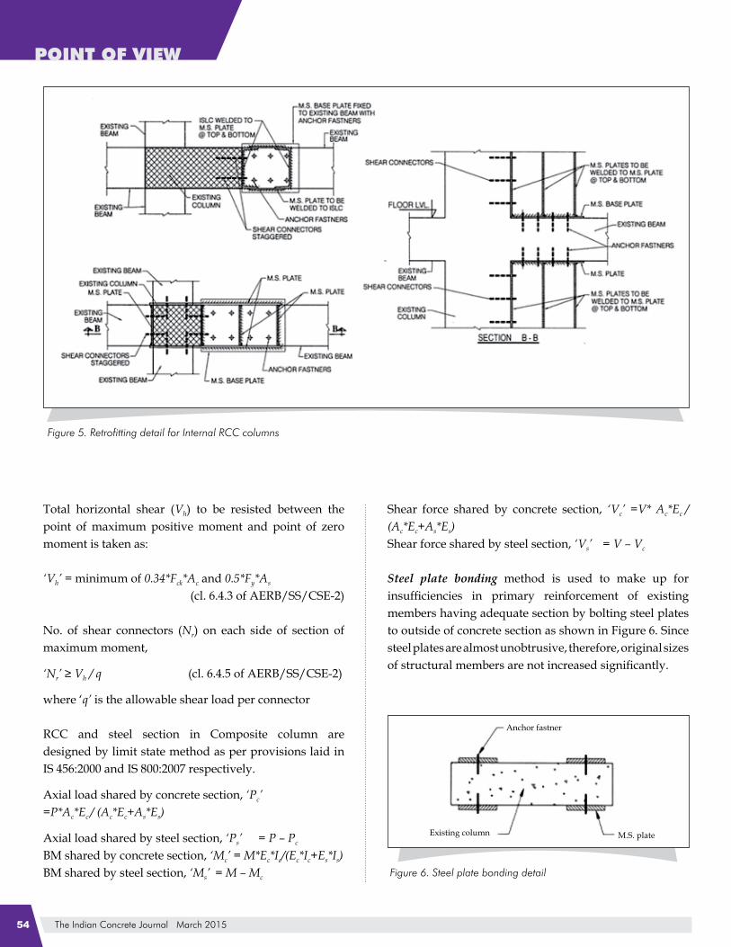
Internal RCC columns are retrofitted with steel section as per Figure 5 to have least disturbance to ongoing activities in particular area and to reduce time of implementation of retrofitting scheme.
For full composite action of steel and concrete, Shear connectors between existing and new RCC members and between RCC and steel members are designed as per AERB/SS/CSE-2.
The Indian Concrete Journal March 201554
POINT OF VIEW POINT OF VIEW
Total horizontal shear (Vh) to be resisted between the point of maximum positive moment and point of zero moment is taken as:
‘Vh’ = minimum of 0.34*Fck*Ac and 0.5*Fy*As (cl. 6.4.3 of AERB/SS/CSE-2)
No. of shear connectors (Nr) on each side of section of maximum moment,
‘Nr’ ≥ Vh / q (cl. 6.4.5 of AERB/SS/CSE-2)
where ‘q’ is the allowable shear load per connector
RCC and steel section in Composite column are designed by limit state method as per provisions laid in IS 456:2000 and IS 800:2007 respectively.
Axial load shared by concrete section, ‘Pc’ =P*Ac*Ec / (Ac*Ec+As*Es)
Axial load shared by steel section, ‘Ps’ = P – Pc
BM shared by concrete section, ‘Mc’ = M*Ec*Ic/(Ec*Ic+Es*Is)BM shared by steel section, ‘Ms’ = M – Mc
Shear force shared by concrete section, ‘Vc’ =V* Ac*Ec / (Ac*Ec+As*Es)Shear force shared by steel section, ‘Vs’ = V – Vc
Steel plate bonding method is used to make up for insufficiencies in primary reinforcement of existing members having adequate section by bolting steel plates to outside of concrete section as shown in Figure 6. Since steel plates are almost unobtrusive, therefore, original sizes of structural members are not increased significantly.

The Indian Concrete Journal March 2015 55
POINT OF VIEW
Steel bracings in selected bays of peripheral frames are provided as per Figure 7 to increase lateral resistance, to control displacement and balance stiffness distribution within a storey & thereby reduce torsion irregularities. The additional advantages are negligible added weight to structure, flexibility in its distribution and possibility of performing construction work from outside which limits disruption to occupants. Though steel bracings increase the seismic demand due to greater stiffness but it also increases the performance of building.
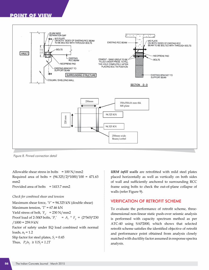
Pinned connection is provided as per detail shown in Figure 8 at location of separation gap between vault wall and surrounding structure as gap width found during check analysis was insufficient to avoid pounding during earthquake.
MS plate design
Bending moment to be resisted by plate, ‘M’ = 94.325*0.22 = 20.75 kNm
Provide plate of size 350*350*16 mm thick on both sides of beam
Section modulus about vertical axis, ‘Zy-y’ = (0.35*0.282³/12-0.35*0.25³/12)/0.141
= 0.001407 m³
Section modulus about horizontal axis, ‘Zx-x’ =(0.282*0.35³/12-0.25*0.35³/12)/0.175
= 0.000653 m³
Actual bending stress = M/Zmin = 31.78 N/mm2
Allowable bending stress = 165 N/mm2
Bolt design
Provide 2-30Ø bolts @ Top and bottom
Check for tension
Maximum tension = 94.325 kNAllowable stress in axial tension = 120 N/mm2Required net area of bolts = 94.325*1000/120 = 786 mm2Area at root of thread of 30Ø bolt, ‘Ar’ = 565 mm2Provided net area of bolts = 565*2 = 1130 mm2
Check for shear
Maximum shear force = 94.325 kN (double shear)
The Indian Concrete Journal March 201556
POINT OF VIEW POINT OF VIEW
Allowable shear stress in bolts = 100 N/mm2Required area of bolts = (94.325/2)*1000/100 = 471.63 mm2Provided area of bolts = 1413.7 mm2
Check for combined shear and tension
Maximum shear force, ‘V’ = 94.325 kN (double shear)Maximum tension, ‘T’ = 67.46 kNYield stress of bolt, ‘Fy’ = 230 N/mm2Proof load of 2-30Ø bolts, ‘Pr’ = Ar * Fy = (2*565)*230 /1000 = 259.9 kNFactor of safety under EQ load combined with normal loads, nf = 1.2Slip factor for steel plates, Sf = 0.45Thus, Pr/nf ≥ V/Sf + 1.2T
URM infill walls are retrofitted with mild steel plates placed horizontally as well as vertically on both sides of wall and sufficiently anchored to surrounding RCC frame using bolts to check the out-of-plane collapse of walls (refer Figure 9).
VERIFICATION OF RETROFIT SCHEME
To evaluate the performance of retrofit scheme, three-dimensional non-linear static push-over seismic analysis is performed with capacity spectrum method as per ATC-40 using SAP2000, which shows that selected retrofit scheme satisfies the identified objective of retrofit and performance point obtained from analysis closely matched with ductility factor assumed in response spectra analysis.

The Indian Concrete Journal March 2015 57
POINT OF VIEW
Further, Integrity and confirmatory test is proposed by ultrasonic pulse velocity (USPV) conforming to IS: 13311 (part 1) at retrofitted portion, both pre and post retrofitting of structural member at same cross-sectional plane to identify weak locations possessing loss of integrity and presence of voids in concrete, thus giving fair idea about effectiveness of retrofitting.
CONCLUSION
Superconducting cyclotron is an accelerator classified as nuclear facility with limited radioactive inventory and a rational way to categorize such facilities is based on intended design objective of the facility and the consequent risk associated with it in the event of failure on structures, systems and components relevant to the facility. Based on these criteria, SCC facility is classified as safety class 3, seismic category 2 and to be designed for design class 2.
Seismic safety re-evaluation of SCC facility was needed due to improvements in national and international standards for seismic design of such facilities. In order to assess performance of structure against design earthquake, three-dimensional finite element model in as-is condition is developed. Seismic analysis performed using linear dynamic response spectrum analysis and non-linear static push-over analysis shows that as-built structure
needs strengthening to enhance the seismic safety in compliance with the present codal requirements.
As the facility is in operation, it was difficult to choose retrofitting scheme because of the associated radiation fields. Retrofitting scheme was selectively chosen with column section enhancement, steel bracing and pinned connectivity between radiation shielded vault with surrounding structure satisfy requirements of upgraded seismic codes and effectively raise the performance of building to a desired level, without significantly interfering with architectural features of building and usage.
Acknowledgement
The work presented here is a part of seismic assessment and subsequently proposed retrofitting scheme for SCC facility at VECC Kolkata. We gratefully acknowledge the assistance of Dr. G. R. Reddy and Sh. Akanshu Sharma, Bhabha Atomic Research Centre Mumbai for performing push-over analysis.
ReferencesN. S. Gabhane, R. Sharma, S. K. Saini, G. R. Reddy and Kapilesh Bhargava, Study of seismic response of structure under alternative measures of seismic up gradation, Paper presented at the International Conference on Structural Mechanics in Reactor Technology (SMiRT 21), November 2011, New Delhi, India
1.

The Indian Concrete Journal March 201558
POINT OF VIEW
_____Consideration of external events in the design of nuclear facilities other than nuclear power plants, with emphasis on earthquakes, IAEA-TECDOC-1347, International Atomic Energy Agency, Vienna, Austria.
_____Seismic evaluation and retrofit of concrete buildings, ATC-40, Volume 1, Applied Technology Council, California
_____AERB safety standard for Design of Concrete Structures Important to Safety of Nuclear Facilities, AERB/SS/CSE-1, Atomic Energy Regulatory Board, Mumbai, India.
_____AERB safety standard for Design, Fabrication and Erection of Steel structures Important to Safety of Nuclear Facilities, AERB/SS/CSE-2, Atomic Energy Regulatory Board, Mumbai, India.
_____AERB safety guidelines on Accelerators, AERB/SG/IS-5, Atomic Energy Regulatory Board, Mumbai, India.
_____Indian standard criteria for earthquake resistant design of structures – Industrial structures including stack-like structures, IS 1893 (Part 4): 2005, Bureau of Indian Standards, New Delhi, India.
_____Indian standard criteria for earthquake resistant design of structures – General provisions and buildings, IS 1893 (Part 1): 2002, Bureau of Indian Standards, New Delhi, India.
2.
3.
4.
5.
6.
7.
8.
_____Indian standard code of practice for structural use of unreinforced masonry IS: 1905-1987, Bureau of Indian Standards, New Delhi, India.
_____Indian standard code of practice for design and construction of pile foundation – Bored cast in-situ concrete piles, IS: 2911 (Part 1/Sec 2), Bureau of Indian Standards, India.
____Indian standard code of practice for plain and reinforced concrete, IS 456:2000, Bureau of Indian Standards, India.
Srinivasulu, P. and Vaidyanathan, C.V., Handbook of Machine foundations, Tata McGraw-Hill publishing company limited, New Delhi, 1976, pp. 206-207.
Nuclear Power Corporation of India Ltd., Preliminary safety analysis report – part A, Section 3, part 1 on Rajasthan Atomic Power Project – 7 and 8, Jan 2010, pp. 52-53.
____Indian standard for Non-destructive testing of concrete – Methods of test, part 1 ultrasonic pulse velocity, IS 13311 (part 1): 1992, Bureau of Indian Standards, India.
____Indian standard code of practice for General construction in steel, IS 800: 2007, Bureau of Indian Standards, India.
9.
10.
11.
12.
13.
14.
15.
R. Sharma holds an M.E. (Civil) from IISc Bangalore. He is the Chief Engineer and Head Structural Design Section at Directorate of Construction, Services & Estate Management (DCSEM), Dept. of Atomic Energy (DAE), V. S. Bhavan, Anushaktinagar, Mumbai. He has more than 29 years of professional experience in structural design including 2 years with ISRO. He is involved in analysis, design and review of nuclear structures as a member of working group of Civil Engineering Safety Committee of AERB
S.K. Saini holds an M.E. (Structures) from PEC Chandigarh. He is Scientific Officer-E in Structural Design Section at DCSEM, DAE, Mumbai. He has 15 years of structural design experience including 2 years in CSIR. A member of several professional bodies including IEI, he is involved in analysis and design review of nuclear related structures.
N. S. Gabhane, holds B.E. (Electrical) from Nagpur University. He is the Director of DCSEM, DAE, Mumbai. He has more than 35 years of professional experience and is involved in design and execution of safety related projects including review of various nuclear facilities as a member of safety committees constituted by Bhabha Atomic Research Centre ( BARC ) and Atomic Energy Regulatory Board (AERB).