seismic restraint of engineering services - airah · 2 – review the engineering services design...
TRANSCRIPT
Seismic Restraint of Engineering Services
AIRAH July 2014
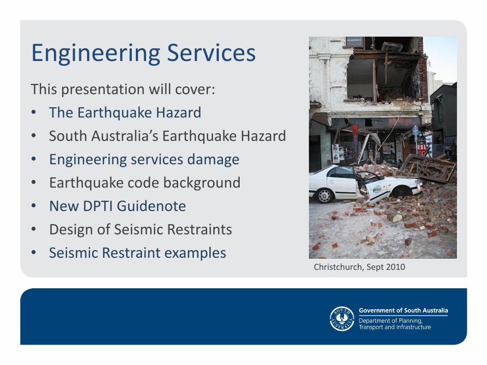
Engineering Services This presentation will cover:
• The Earthquake Hazard
• South Australia’s Earthquake Hazard
• Engineering services damage
• Earthquake code background
• New DPTI Guidenote
• Design of Seismic Restraints
• Seismic Restraint examples Christchurch, Sept 2010
The Earthquake Hazard
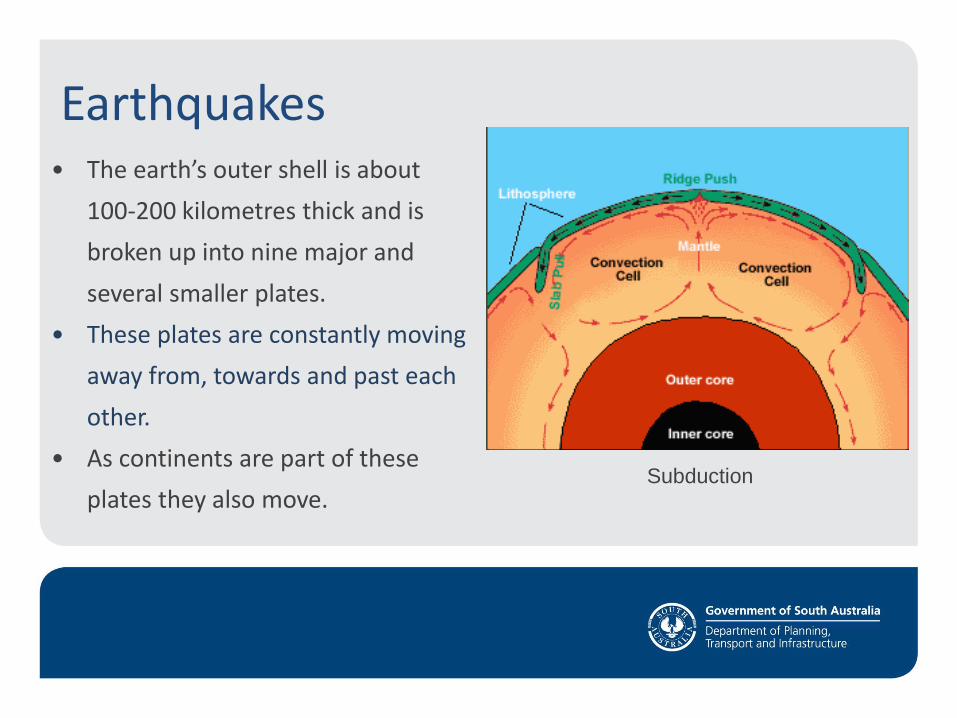
Earthquakes • The earth’s outer shell is about
100-200 kilometres thick and is
broken up into nine major and
several smaller plates.
• These plates are constantly moving
away from, towards and past each
other.
• As continents are part of these
plates they also move.
Subduction
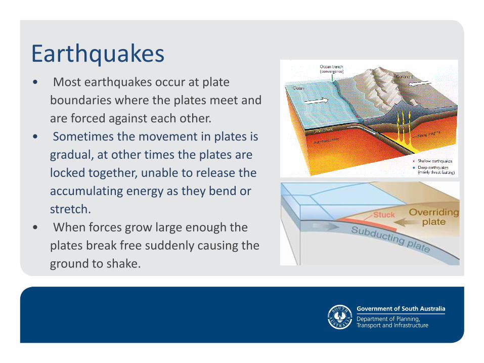
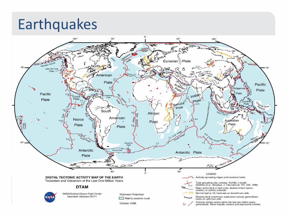
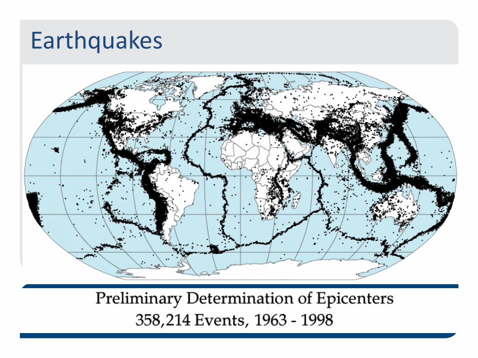
Earthquakes • Most earthquakes occur at plate
boundaries where the plates meet and
are forced against each other.
• Sometimes the movement in plates is
gradual, at other times the plates are
locked together, unable to release the
accumulating energy as they bend or
stretch.
• When forces grow large enough the
plates break free suddenly causing the
ground to shake.
Earthquakes
Earthquakes
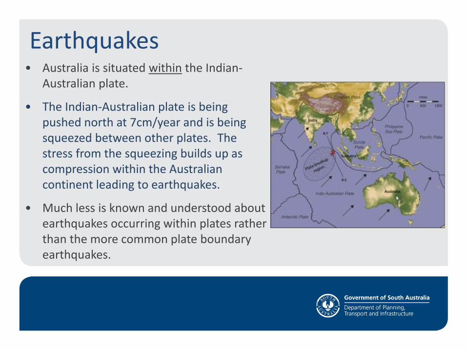
Earthquakes • Australia is situated within the Indian-
Australian plate.
• The Indian-Australian plate is being pushed north at 7cm/year and is being squeezed between other plates. The stress from the squeezing builds up as compression within the Australian continent leading to earthquakes.
• Much less is known and understood about earthquakes occurring within plates rather than the more common plate boundary earthquakes.
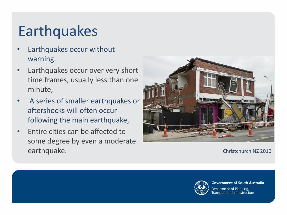
Earthquakes • Earthquakes occur without
warning.
• Earthquakes occur over very short time frames, usually less than one minute,
• A series of smaller earthquakes or aftershocks will often occur following the main earthquake,
• Entire cities can be affected to some degree by even a moderate earthquake. Christchurch NZ 2010
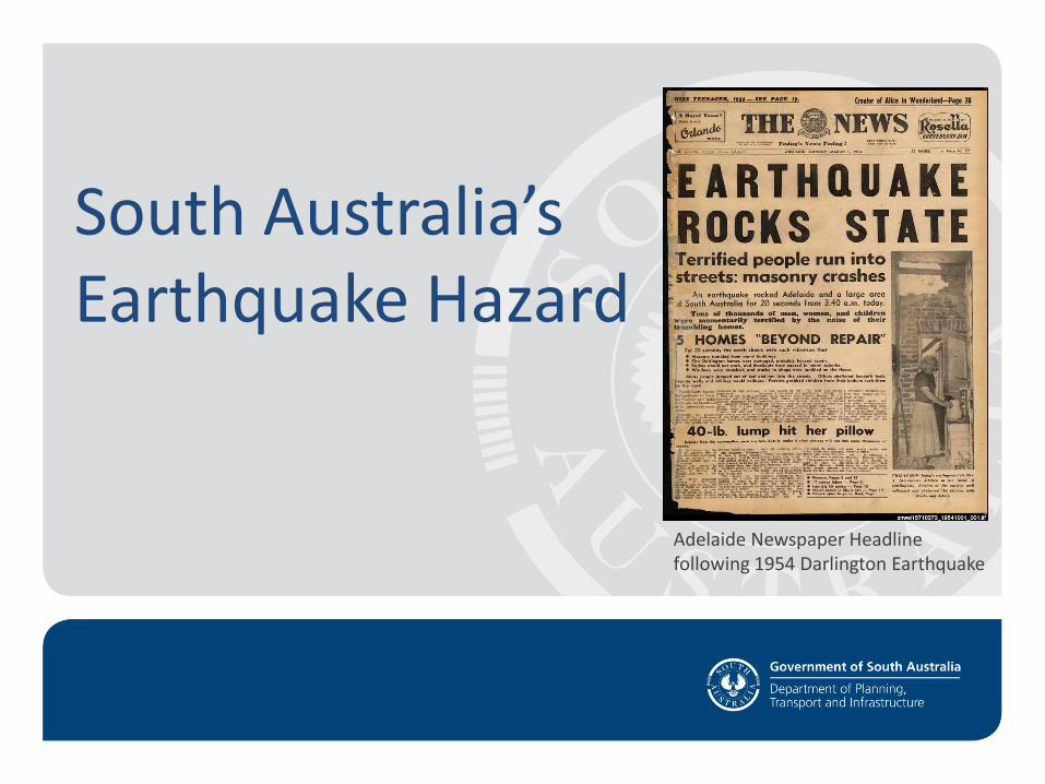
South Australia’s Earthquake Hazard
Adelaide Newspaper Headline following 1954 Darlington Earthquake
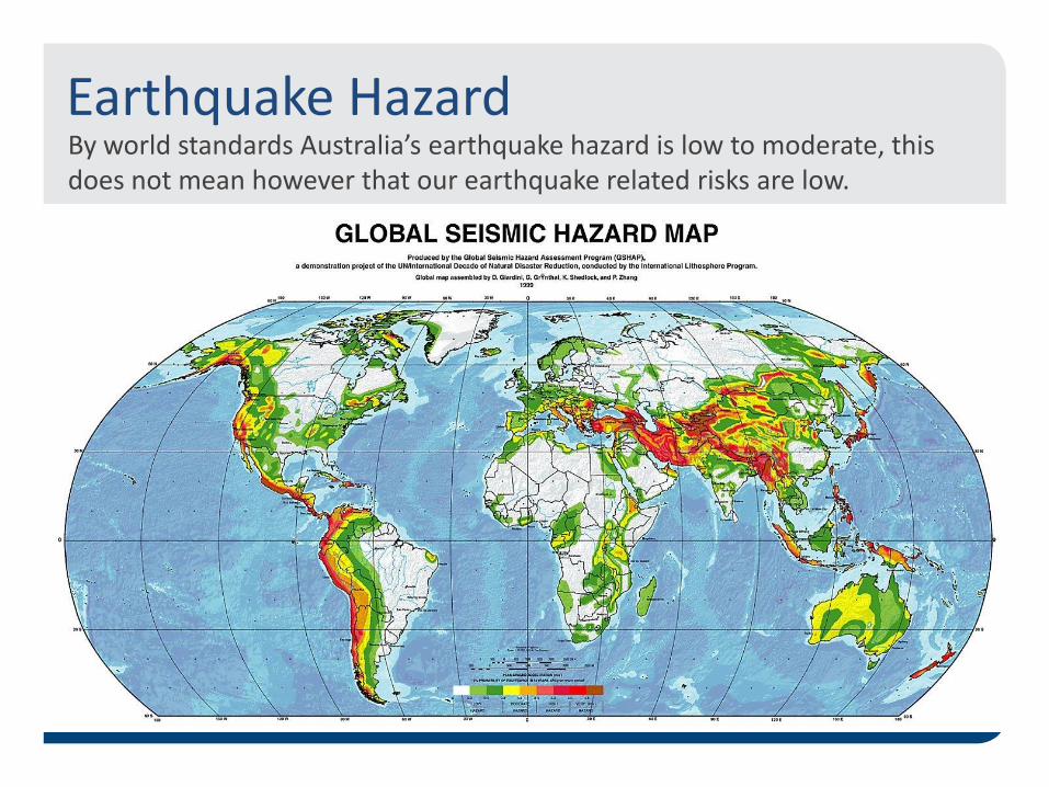
Earthquake Hazard By world standards Australia’s earthquake hazard is low to moderate, this does not mean however that our earthquake related risks are low.
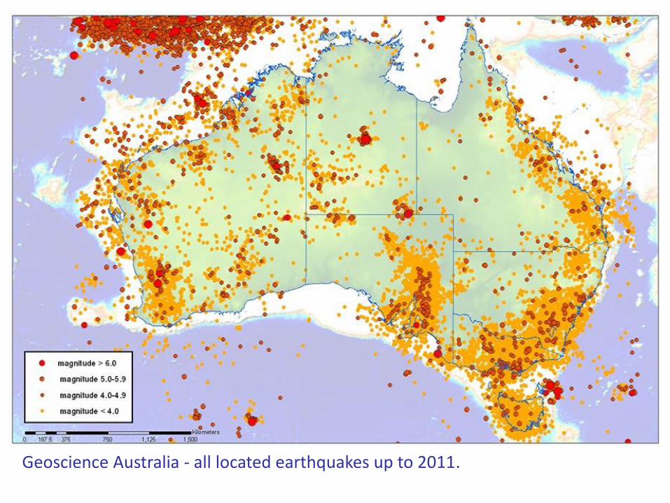
Geoscience Australia - all located earthquakes up to 2011.
Redbanks Fault
Para Fault
M4.4 Gawler 1856
M4.1 Gumeracha 1866
M3.9 Adelaide 1914
M3.1 Adelaide 1977
M2.7 Gawler 1982
M2.3 Modbury 1966

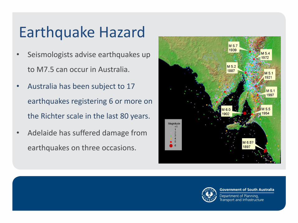
Earthquake Hazard • Seismologists advise earthquakes up
to M7.5 can occur in Australia.
• Australia has been subject to 17
earthquakes registering 6 or more on
the Richter scale in the last 80 years.
• Adelaide has suffered damage from
earthquakes on three occasions.
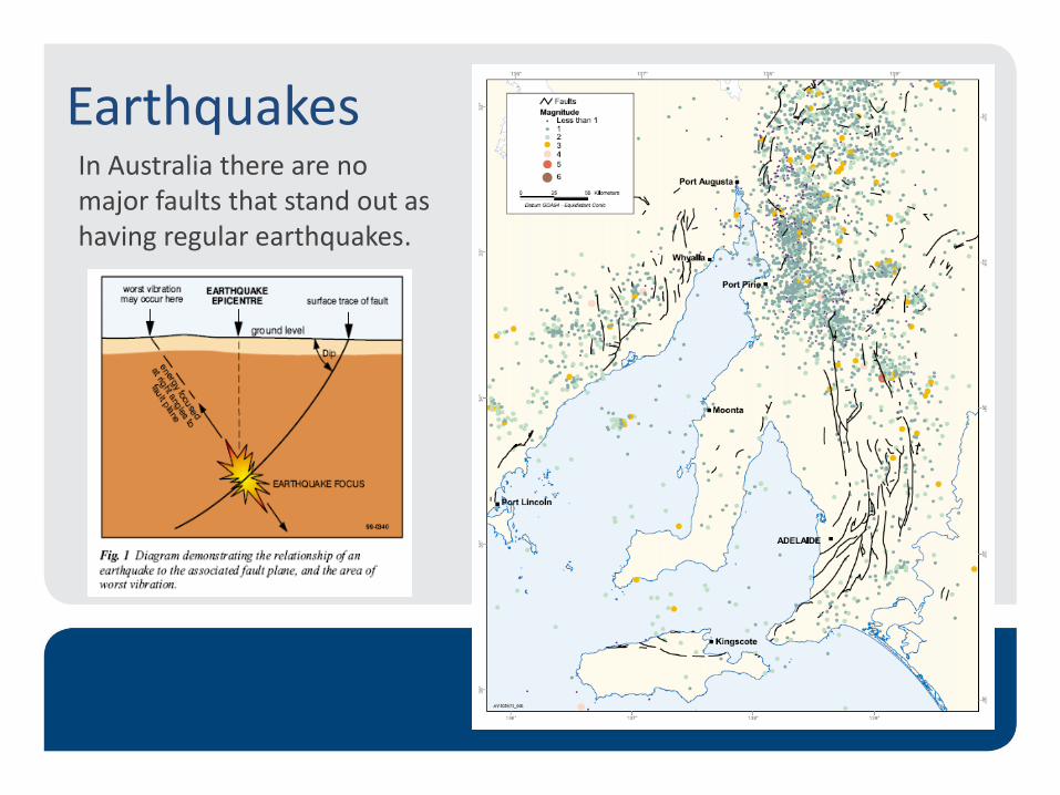
Earthquakes In Australia there are no major faults that stand out as having regular earthquakes.
Engineering services damage in earthquakes
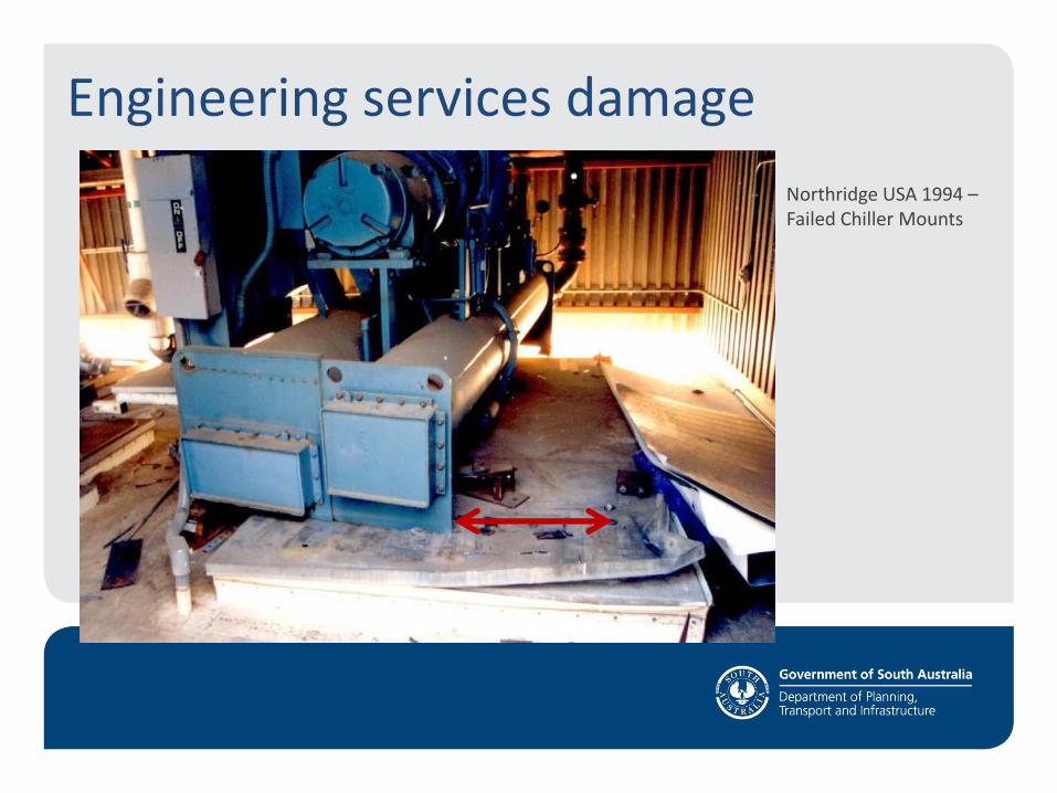
Engineering services damage
Northridge USA 1994 – Failed Chiller Mounts
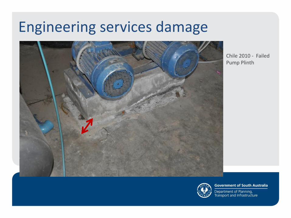
Chile 2010 - Failed Pump Plinth
Engineering services damage
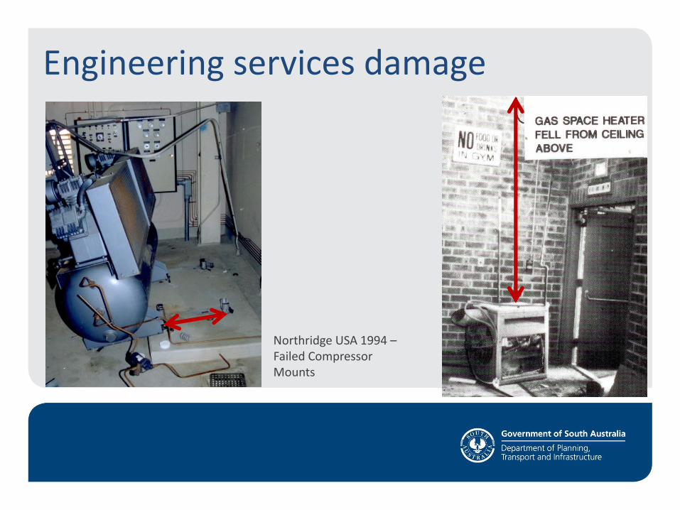
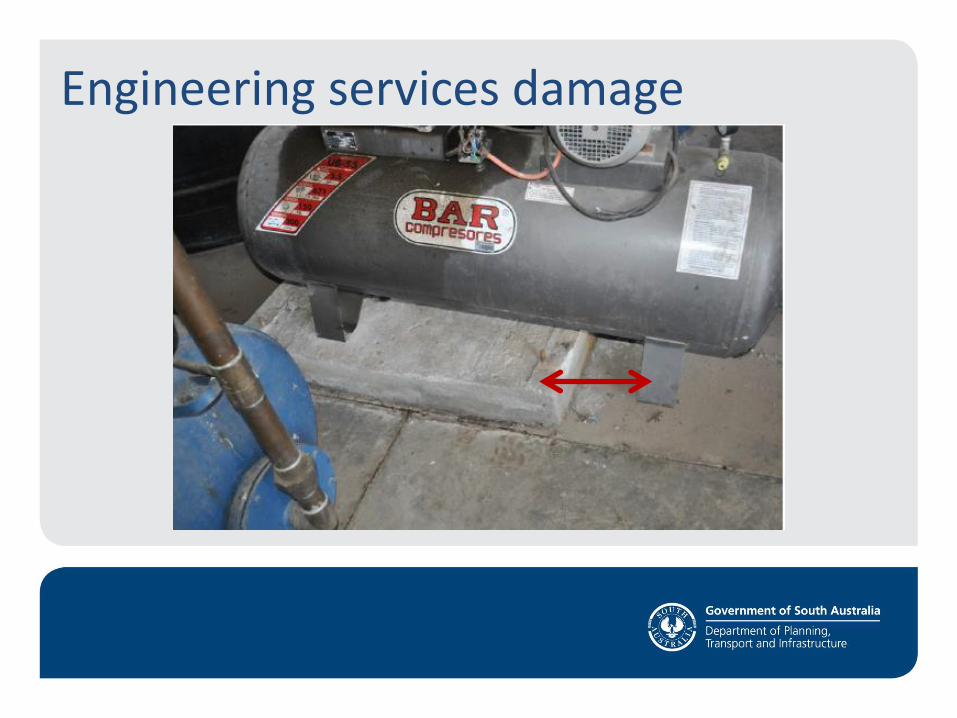
Northridge USA 1994 – Failed Compressor Mounts
Engineering services damage
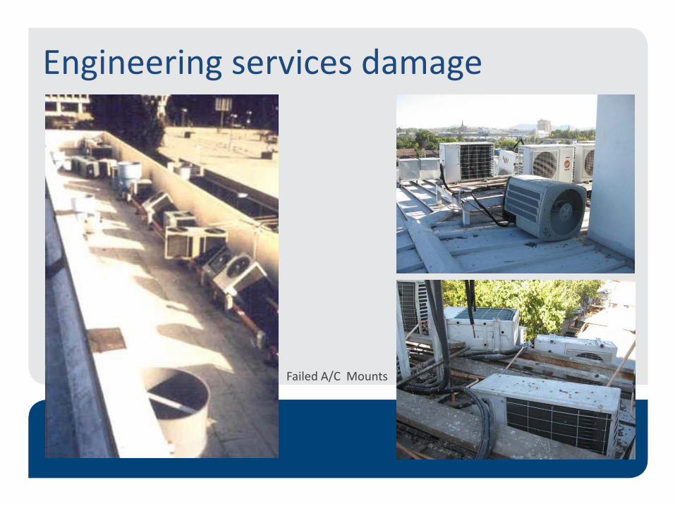
Failed A/C Mounts
Engineering services damage
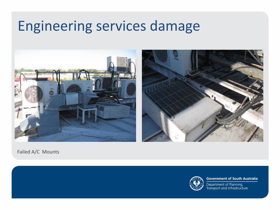
Failed A/C Mounts
Engineering services damage
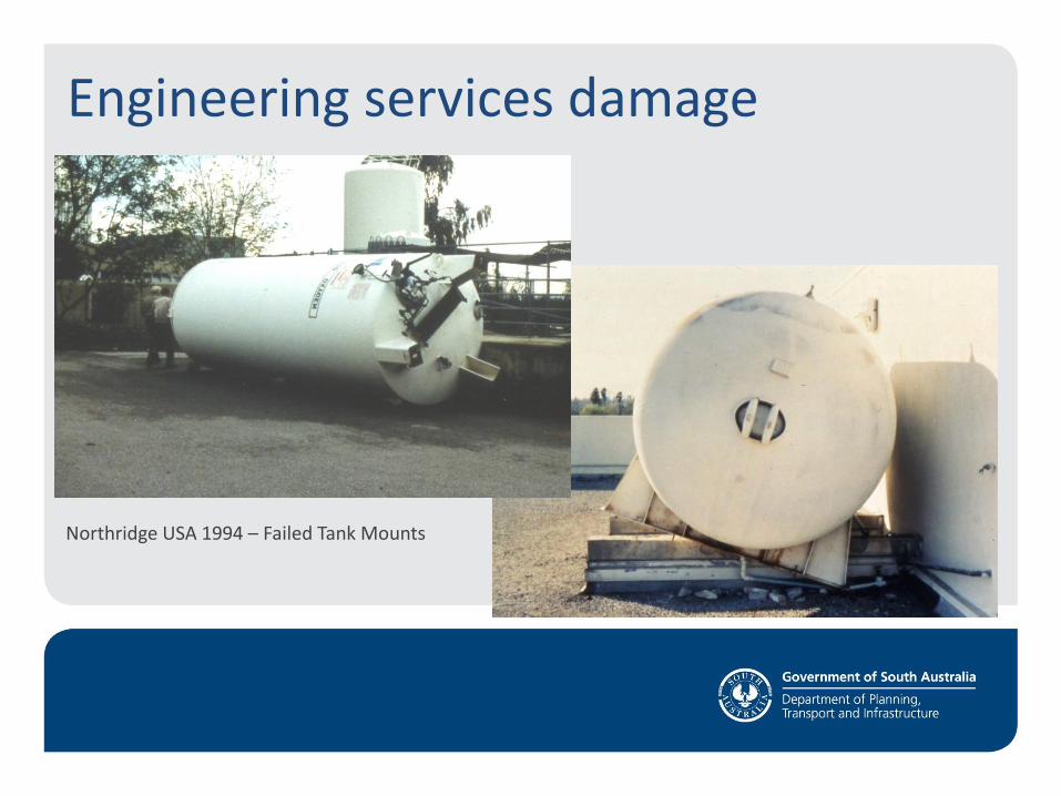
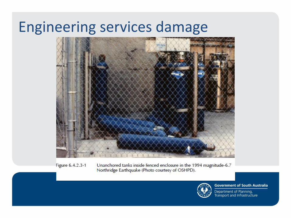
Northridge USA 1994 – Failed Tank Mounts
Engineering services damage
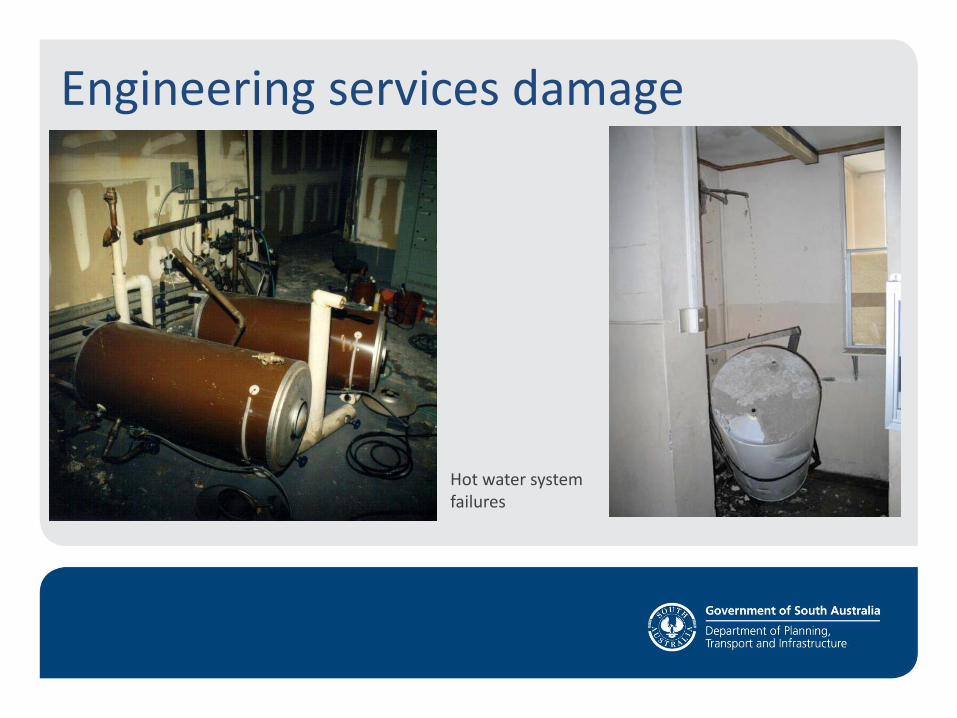
Hot water system failures
Engineering services damage
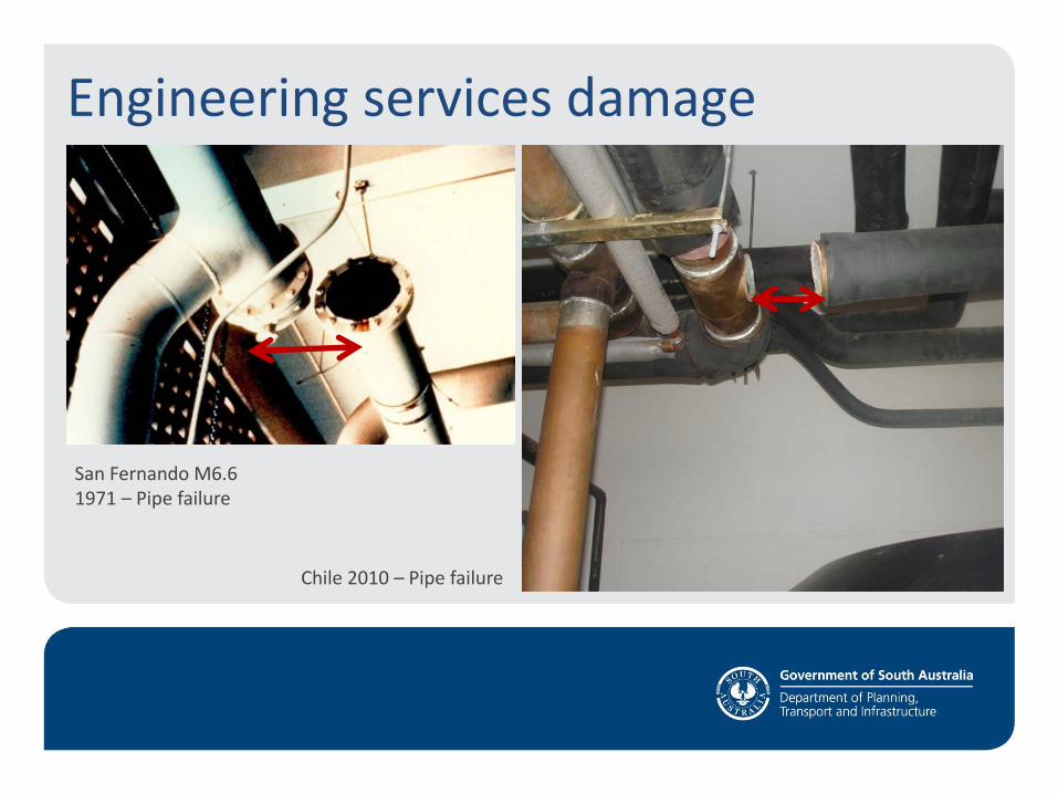
San Fernando M6.6 1971 – Pipe failure
Chile 2010 – Pipe failure
Engineering services damage
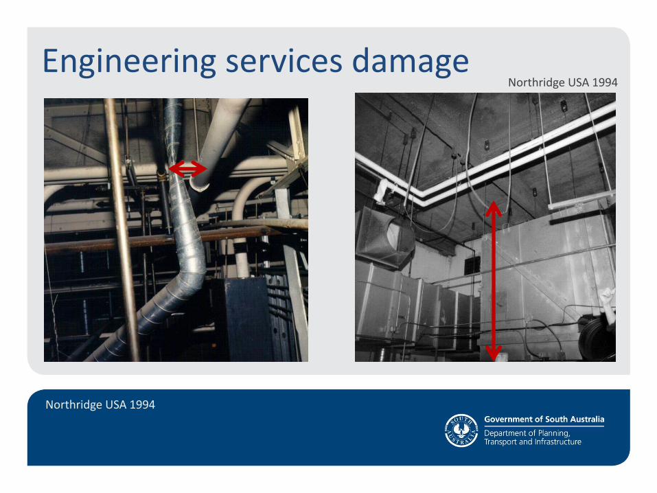
Northridge USA 1994
Northridge USA 1994 Engineering services damage
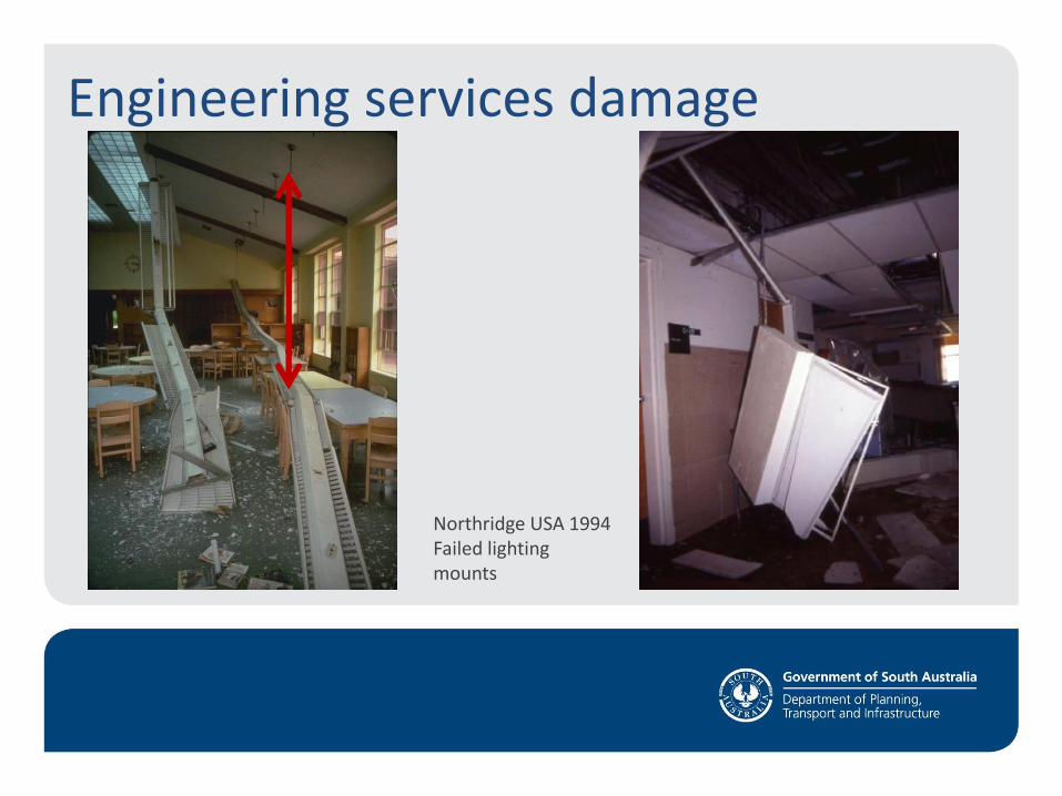
Northridge USA 1994 Failed lighting mounts
Engineering services damage
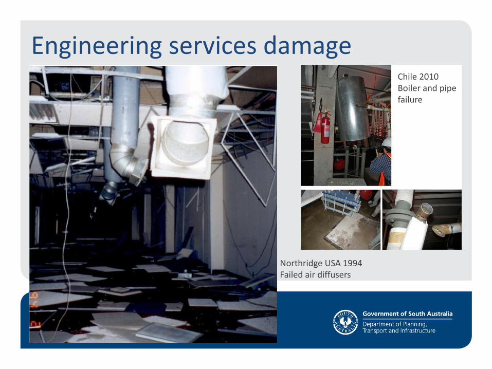
Northridge USA 1994 Failed air diffusers
Engineering services damage Chile 2010 Boiler and pipe failure
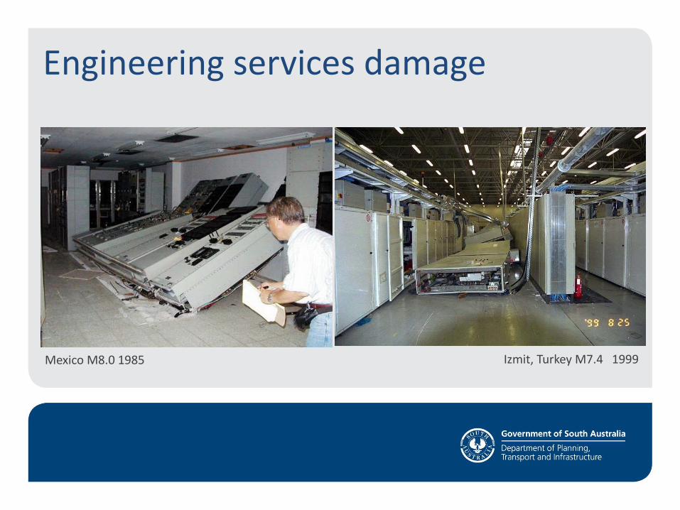
Mexico M8.0 1985 Izmit, Turkey M7.4 1999
Engineering services damage
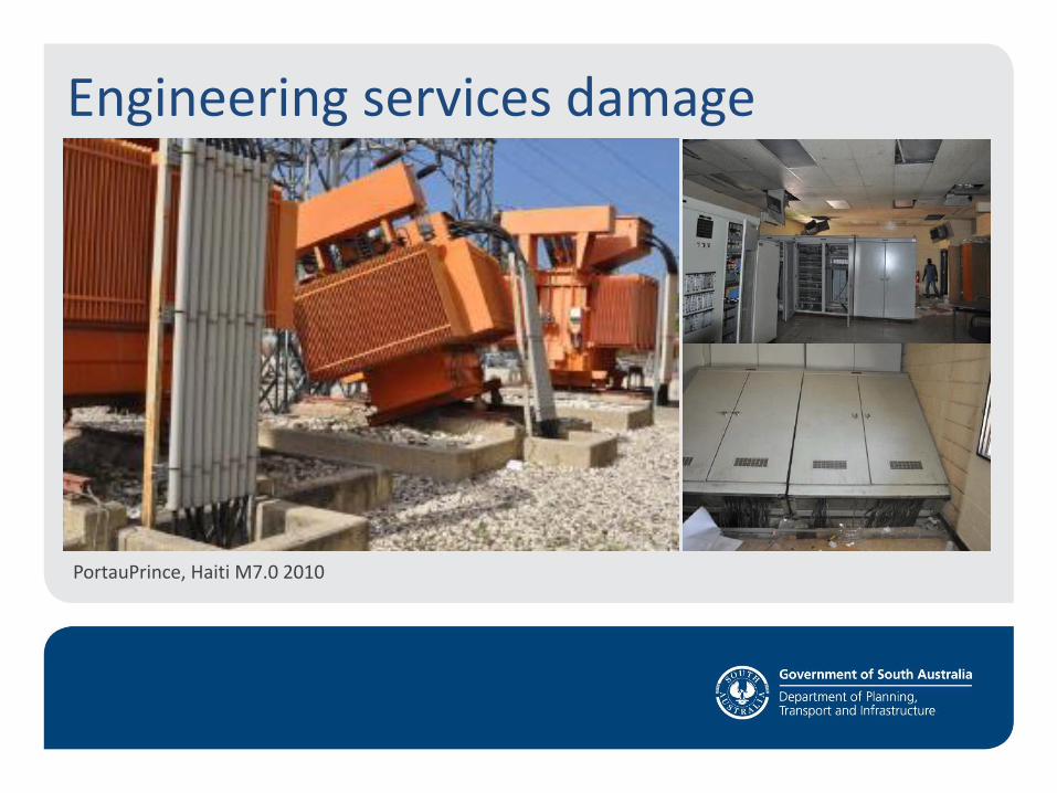
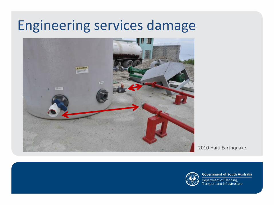
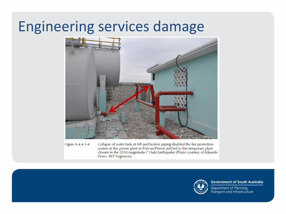
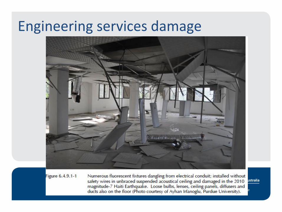
PortauPrince, Haiti M7.0 2010
Engineering services damage
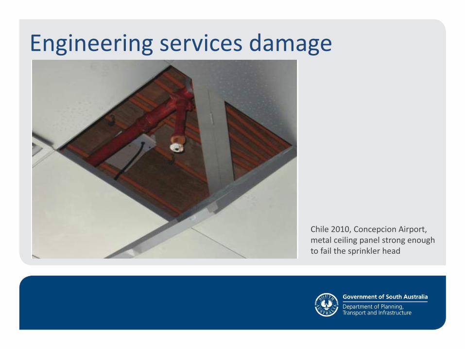
Engineering services damage
Chile 2010, Concepcion Airport, metal ceiling panel strong enough to fail the sprinkler head
Engineering services damage
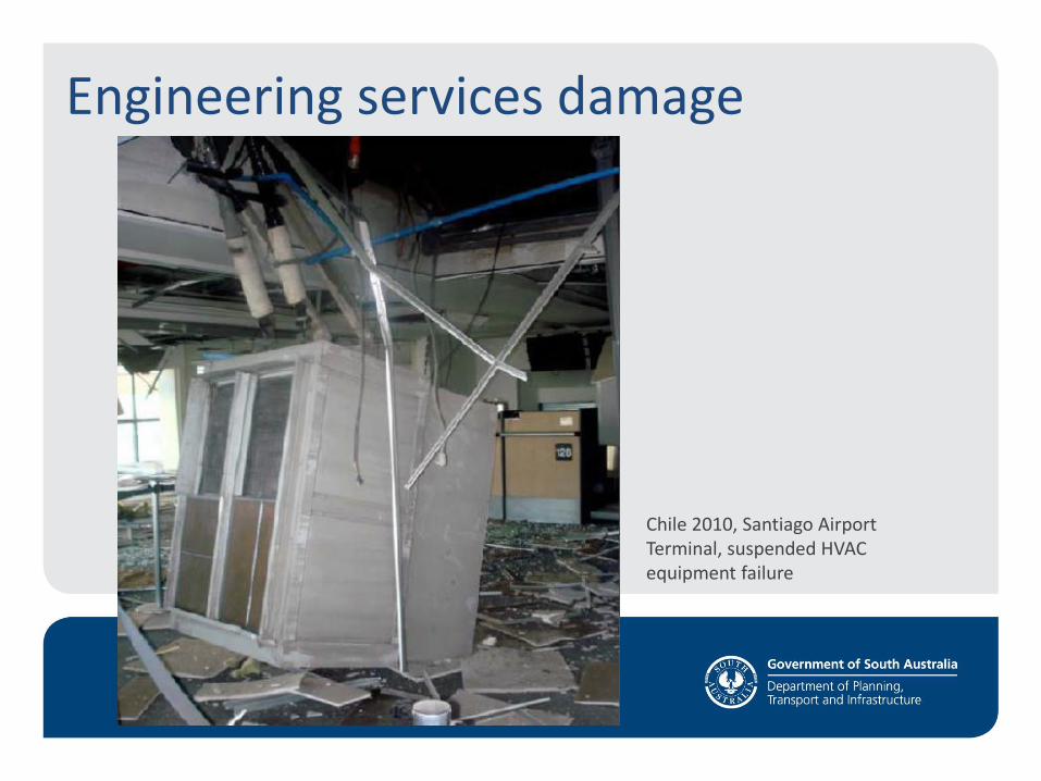
Engineering services damage
Chile 2010, Santiago Airport Terminal, suspended HVAC equipment failure
Engineering services damage

Engineering services damage
Engineering services damage
2010 Haiti Earthquake
Engineering services damage

Engineering services damage
Ducts and equipment shifted in earthquake

Engineering services damage
Plinth broken up by earthquake, unreinforced and unconnected to floor slab

Engineering services damage
Earthquake damage to communication and computer racks
Engineering services damage
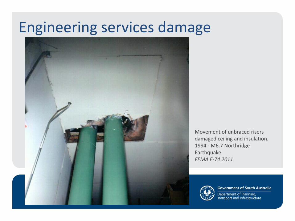
Movement of unbraced risers damaged ceiling and insulation. 1994 - M6.7 Northridge Earthquake FEMA E-74 2011
Engineering services damage
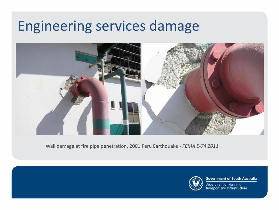
Wall damage at fire pipe penetration. 2001 Peru Earthquake - FEMA E-74 2011
Engineering services damage

Engineering services damage
Chile 2010 – Ceiling, lights and air diffuser failure
Engineering services damage
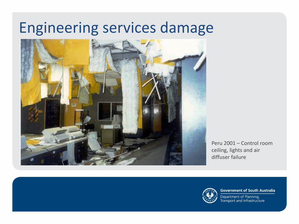
Peru 2001 – Control room ceiling, lights and air diffuser failure
Engineering services damage
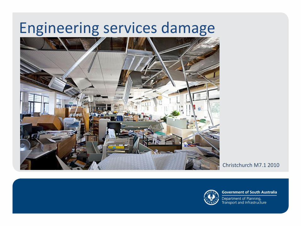
Christchurch M7.1 2010

Engineering services damage
Northridge USA 1994
Northridge USA 1994
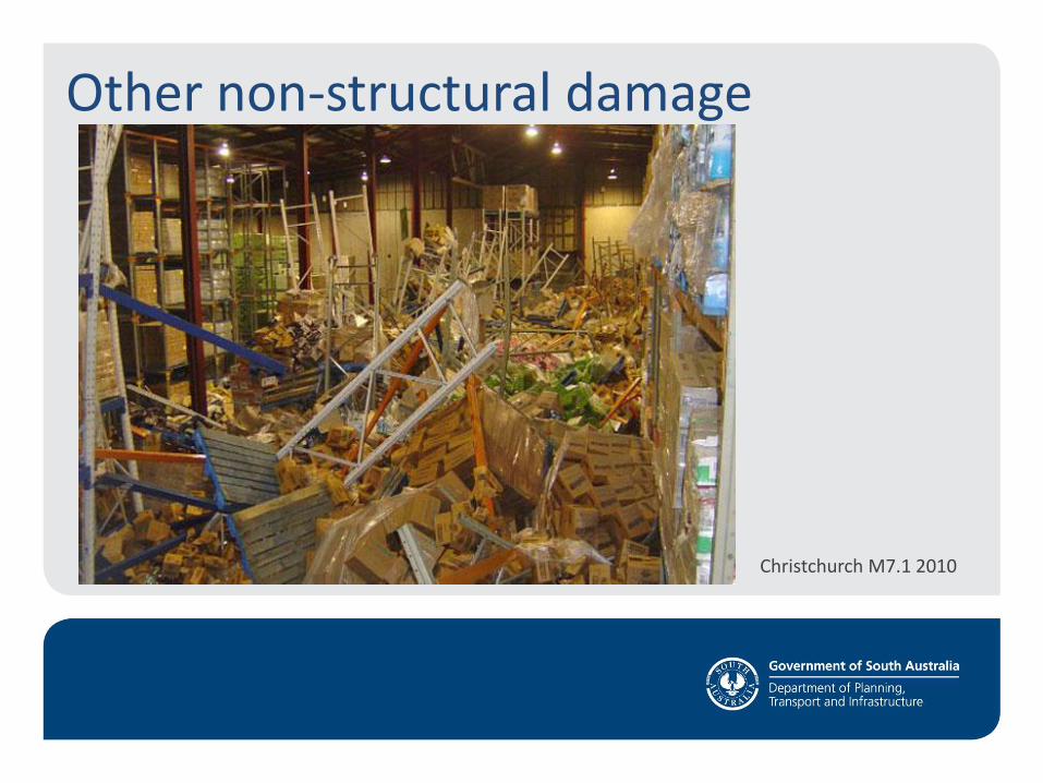
Other non-structural damage
Christchurch M7.1 2010

Other non-structural damage
Christchurch M7.1 2010
Earthquake code background
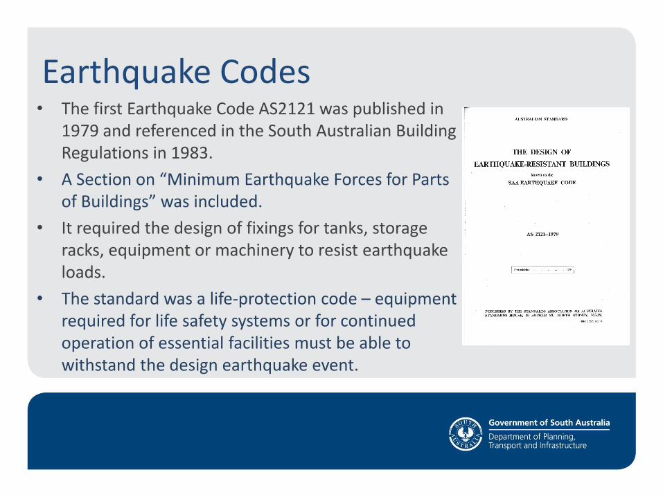
Earthquake Codes • The first Earthquake Code AS2121 was published in
1979 and referenced in the South Australian Building Regulations in 1983.
• A Section on “Minimum Earthquake Forces for Parts of Buildings” was included.
• It required the design of fixings for tanks, storage racks, equipment or machinery to resist earthquake loads.
• The standard was a life-protection code – equipment required for life safety systems or for continued operation of essential facilities must be able to withstand the design earthquake event.
Earthquake Codes
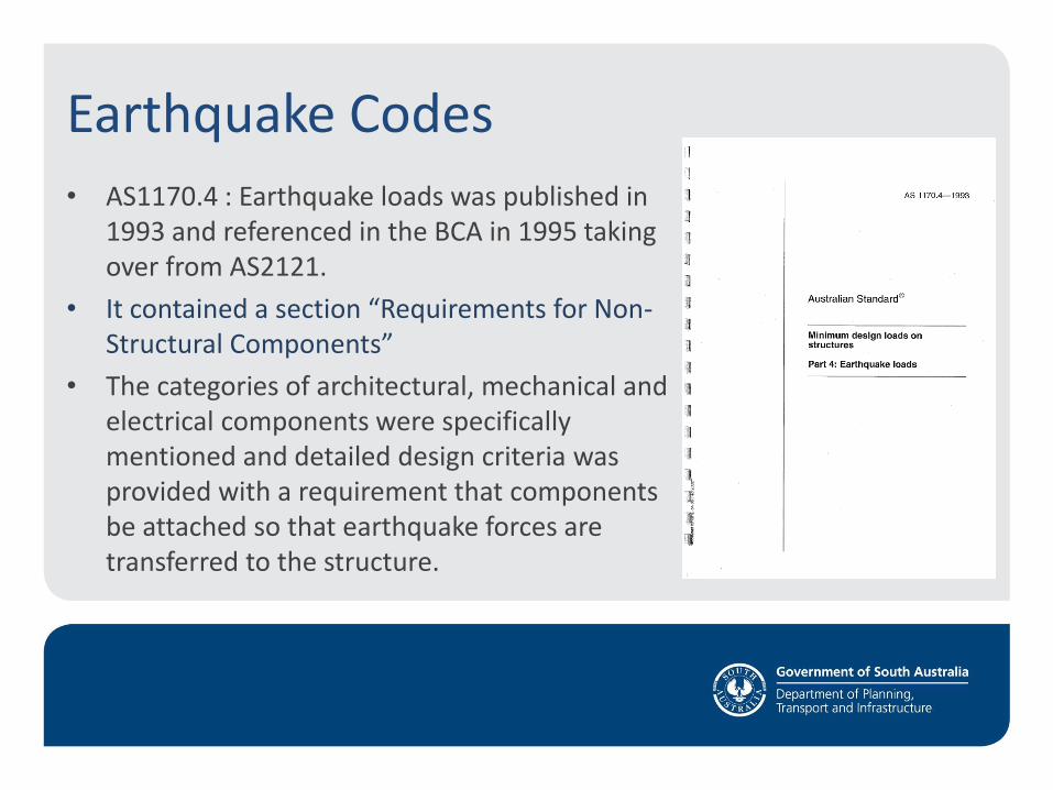
• AS1170.4 : Earthquake loads was published in 1993 and referenced in the BCA in 1995 taking over from AS2121.
• It contained a section “Requirements for Non-Structural Components”
• The categories of architectural, mechanical and electrical components were specifically mentioned and detailed design criteria was provided with a requirement that components be attached so that earthquake forces are transferred to the structure.
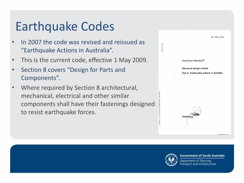
Earthquake Codes • In 2007 the code was revised and reissued as
“Earthquake Actions in Australia”.
• This is the current code, effective 1 May 2009.
• Section 8 covers “Design for Parts and Components”.
• Where required by Section 8 architectural, mechanical, electrical and other similar components shall have their fastenings designed to resist earthquake forces.
New DPTI Guidenote “Seismic Restraint of Engineering Services”
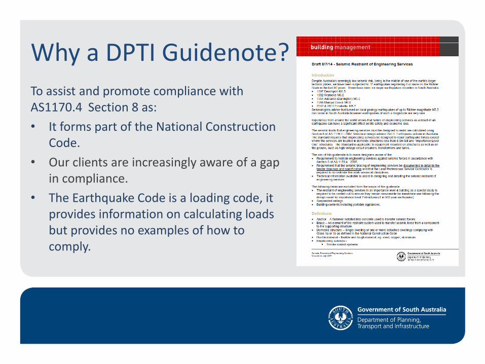
Why a DPTI Guidenote?
To assist and promote compliance with AS1170.4 Section 8 as:
• It forms part of the National Construction Code.
• Our clients are increasingly aware of a gap in compliance.
• The Earthquake Code is a loading code, it provides information on calculating loads but provides no examples of how to comply.
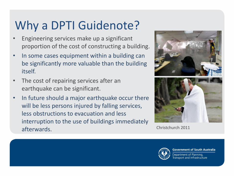
Why a DPTI Guidenote? • Engineering services make up a significant
proportion of the cost of constructing a building.
• In some cases equipment within a building can be significantly more valuable than the building itself.
• The cost of repairing services after an earthquake can be significant.
• In future should a major earthquake occur there will be less persons injured by falling services, less obstructions to evacuation and less interruption to the use of buildings immediately afterwards.
Christchurch 2011
What is in the DPTI Guidenote? • Background to the earthquake hazard in South Australia
• Design responsibility recommendations
• A design methodology using AS1170.4 – 2007 Section 8 including:
– Advice on service clearances
– Advice on spacing of bracing
– Example calculation
– Force diagrams
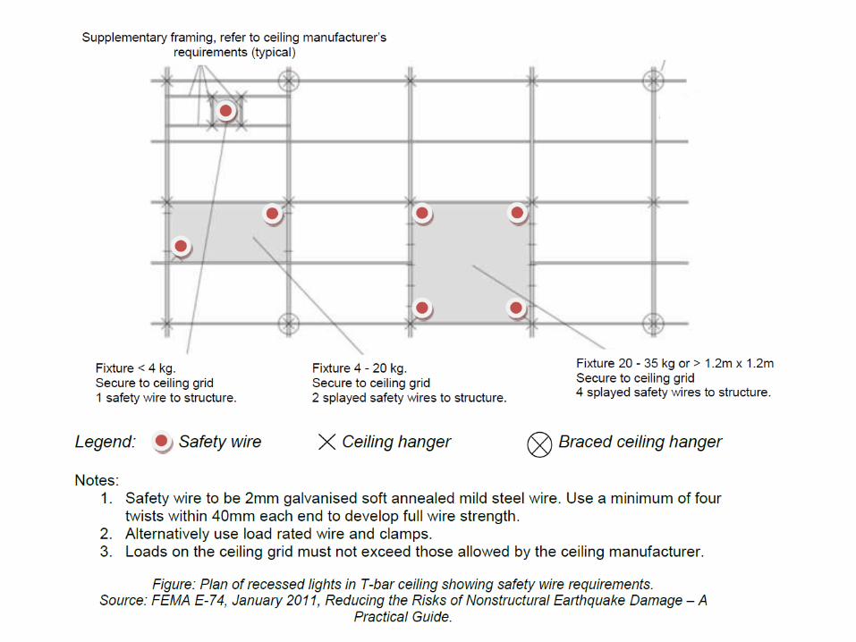
– Safety wire requirements for components in T-bar ceiling systems
– Two drawing sheets with restraint examples
Design of Seismic Restraint of Engineering Services
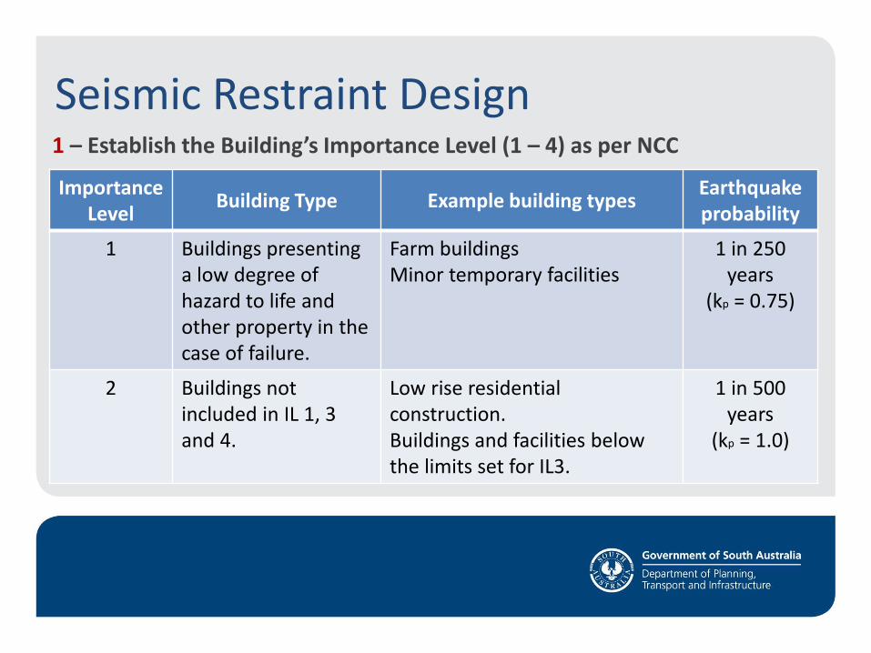
Seismic Restraint Design 1 – Establish the Building’s Importance Level (1 – 4) as per NCC
Importance Level
Building Type Example building types Earthquake probability
1 Buildings presenting a low degree of hazard to life and other property in the case of failure.
Farm buildings Minor temporary facilities
1 in 250 years
(kp = 0.75)
2 Buildings not included in IL 1, 3 and 4.
Low rise residential construction. Buildings and facilities below the limits set for IL3.
1 in 500 years
(kp = 1.0)
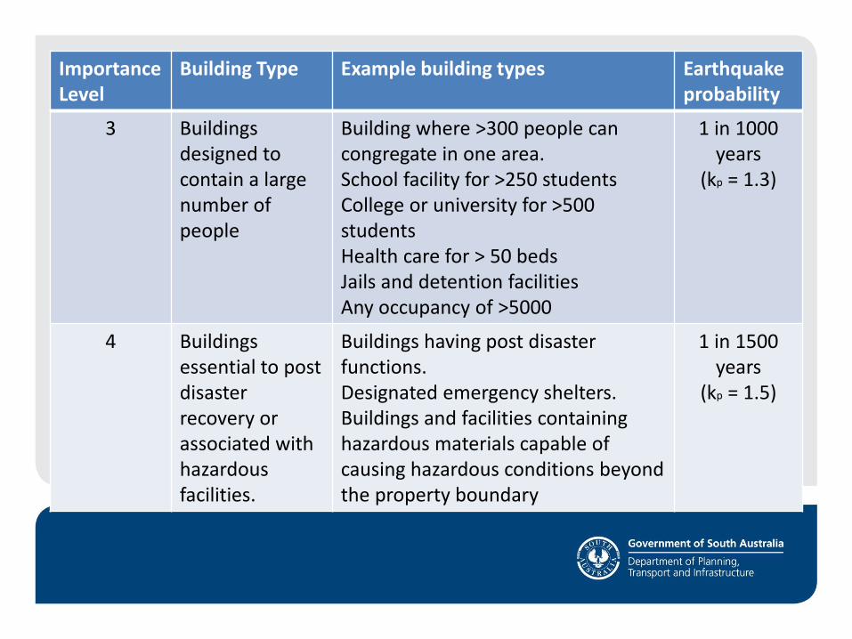
Importance Level
Building Type Example building types Earthquake probability
3 Buildings designed to contain a large number of people
Building where >300 people can congregate in one area. School facility for >250 students College or university for >500 students Health care for > 50 beds Jails and detention facilities Any occupancy of >5000
1 in 1000 years
(kp = 1.3)
4 Buildings essential to post disaster recovery or associated with hazardous facilities.
Buildings having post disaster functions. Designated emergency shelters. Buildings and facilities containing hazardous materials capable of causing hazardous conditions beyond the property boundary
1 in 1500 years
(kp = 1.5)
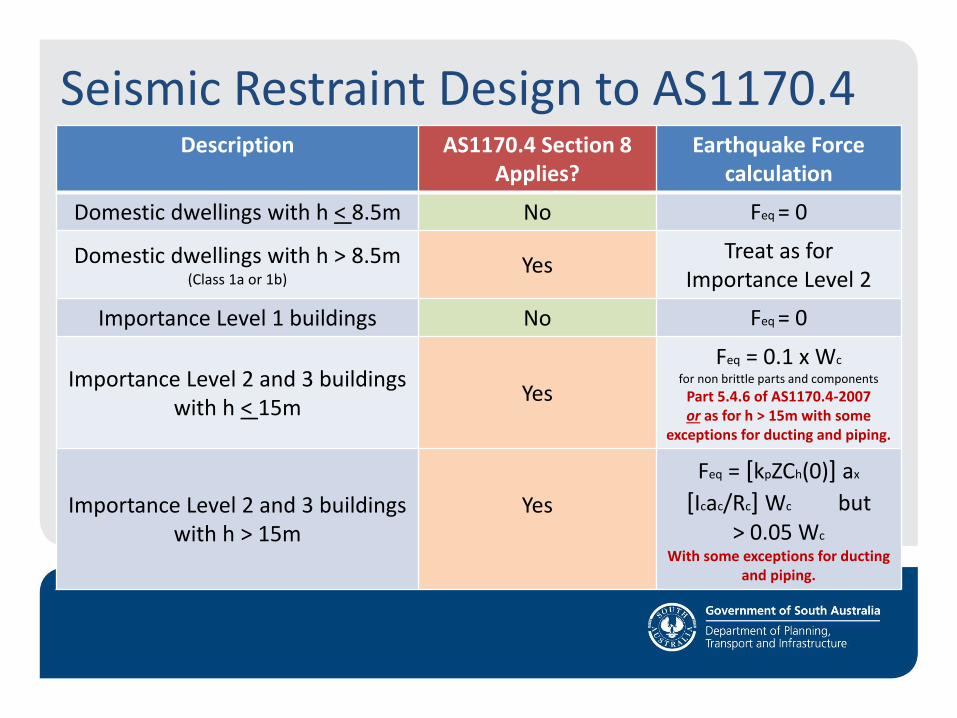
Seismic Restraint Design to AS1170.4 Description AS1170.4 Section 8
Applies? Earthquake Force
calculation
Domestic dwellings with h < 8.5m No Feq = 0
Domestic dwellings with h > 8.5m (Class 1a or 1b)
Yes Treat as for
Importance Level 2
Importance Level 1 buildings No Feq = 0
Importance Level 2 and 3 buildings with h < 15m
Yes
Feq = 0.1 x Wc
for non brittle parts and components
Part 5.4.6 of AS1170.4-2007 or as for h > 15m with some
exceptions for ducting and piping.
Importance Level 2 and 3 buildings with h > 15m
Yes
Feq = [kpZCh(0)] ax
[Icac/Rc] Wc but > 0.05 Wc
With some exceptions for ducting and piping.
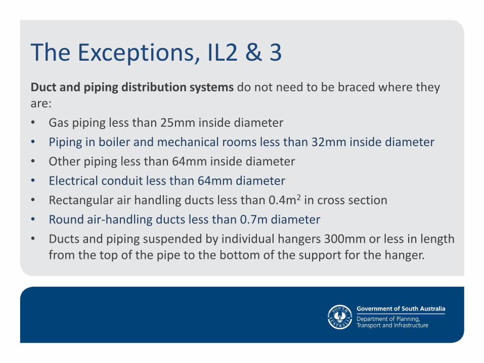
The Exceptions, IL2 & 3 Duct and piping distribution systems do not need to be braced where they are:
• Gas piping less than 25mm inside diameter
• Piping in boiler and mechanical rooms less than 32mm inside diameter
• Other piping less than 64mm inside diameter
• Electrical conduit less than 64mm diameter
• Rectangular air handling ducts less than 0.4m2 in cross section
• Round air-handling ducts less than 0.7m diameter
• Ducts and piping suspended by individual hangers 300mm or less in length from the top of the pipe to the bottom of the support for the hanger.
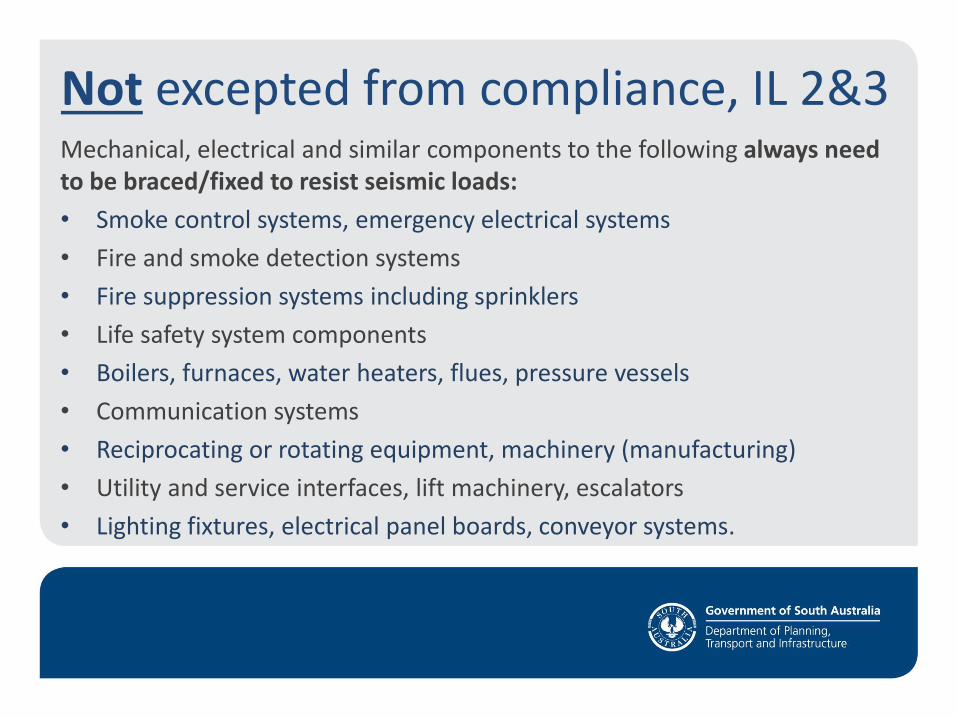
Not excepted from compliance, IL 2&3 Mechanical, electrical and similar components to the following always need to be braced/fixed to resist seismic loads:
• Smoke control systems, emergency electrical systems
• Fire and smoke detection systems
• Fire suppression systems including sprinklers
• Life safety system components
• Boilers, furnaces, water heaters, flues, pressure vessels
• Communication systems
• Reciprocating or rotating equipment, machinery (manufacturing)
• Utility and service interfaces, lift machinery, escalators
• Lighting fixtures, electrical panel boards, conveyor systems.
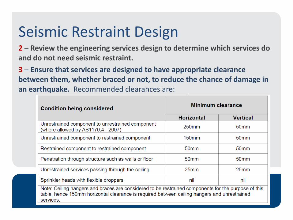
Seismic Restraint Design 2 – Review the engineering services design to determine which services do and do not need seismic restraint.
3 – Ensure that services are designed to have appropriate clearance between them, whether braced or not, to reduce the chance of damage in an earthquake. Recommended clearances are:
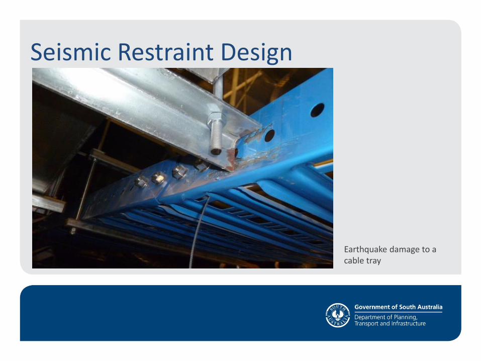
Seismic Restraint Design
Earthquake damage to a cable tray
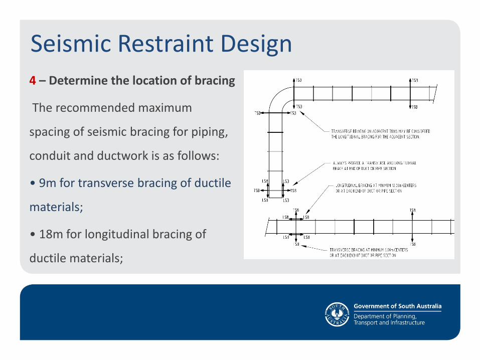
Seismic Restraint Design 4 – Determine the location of bracing
The recommended maximum
spacing of seismic bracing for piping,
conduit and ductwork is as follows:
• 9m for transverse bracing of ductile
materials;
• 18m for longitudinal bracing of
ductile materials;
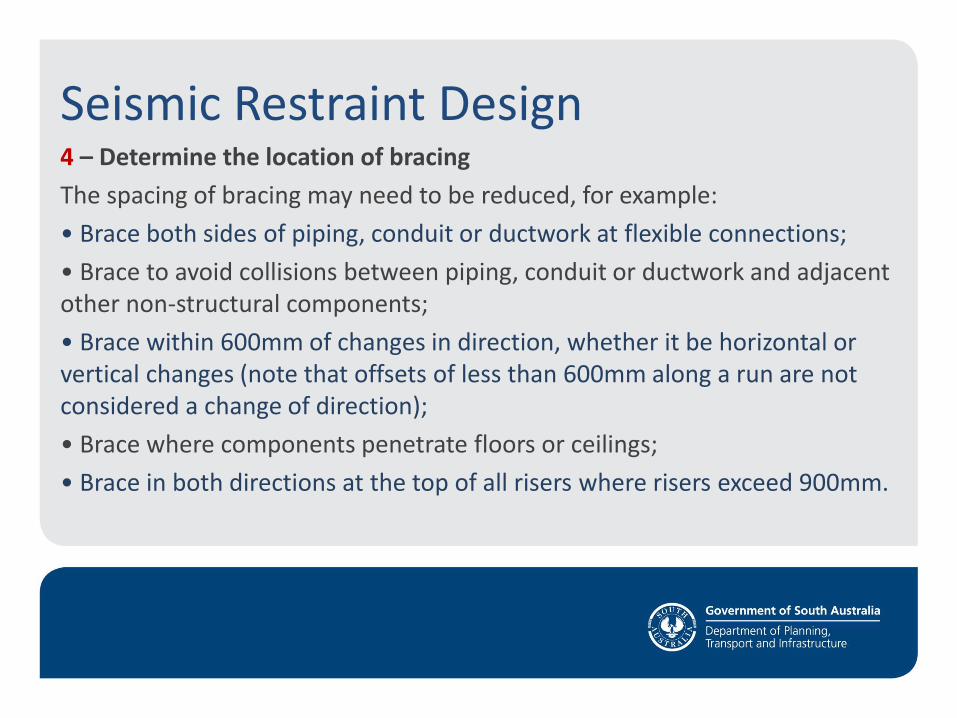
Seismic Restraint Design 4 – Determine the location of bracing
The spacing of bracing may need to be reduced, for example:
• Brace both sides of piping, conduit or ductwork at flexible connections;
• Brace to avoid collisions between piping, conduit or ductwork and adjacent other non-structural components;
• Brace within 600mm of changes in direction, whether it be horizontal or vertical changes (note that offsets of less than 600mm along a run are not considered a change of direction);
• Brace where components penetrate floors or ceilings;
• Brace in both directions at the top of all risers where risers exceed 900mm.
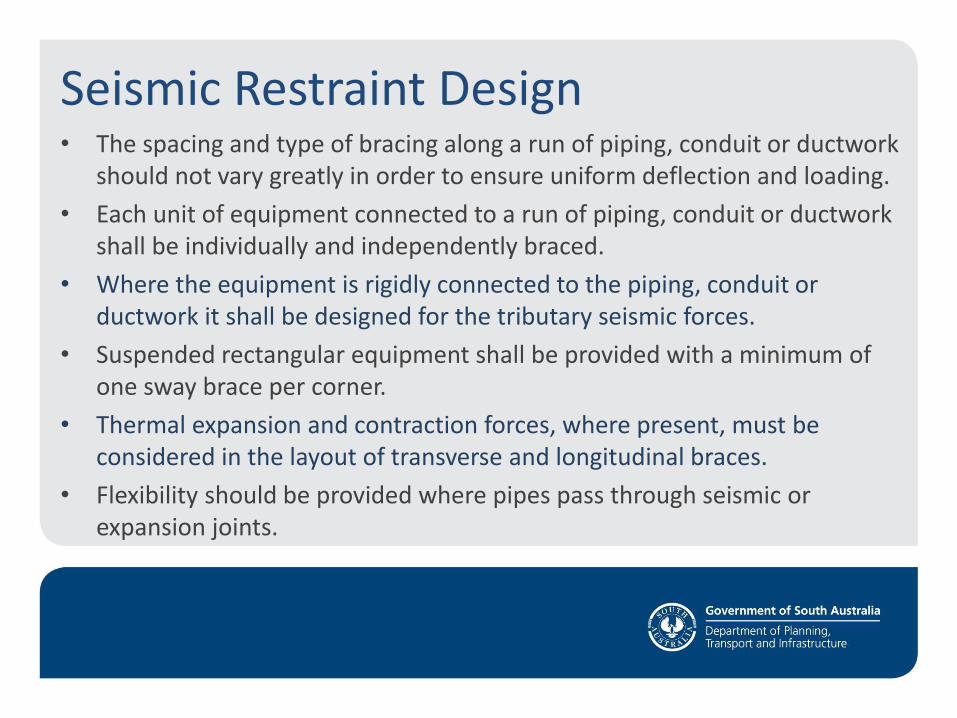
Seismic Restraint Design • The spacing and type of bracing along a run of piping, conduit or ductwork
should not vary greatly in order to ensure uniform deflection and loading.
• Each unit of equipment connected to a run of piping, conduit or ductwork shall be individually and independently braced.
• Where the equipment is rigidly connected to the piping, conduit or ductwork it shall be designed for the tributary seismic forces.
• Suspended rectangular equipment shall be provided with a minimum of one sway brace per corner.
• Thermal expansion and contraction forces, where present, must be considered in the layout of transverse and longitudinal braces.
• Flexibility should be provided where pipes pass through seismic or expansion joints.
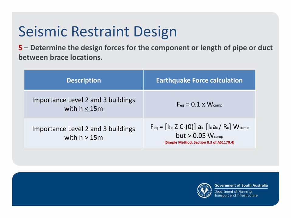
Seismic Restraint Design 5 – Determine the design forces for the component or length of pipe or duct between brace locations.
Description Earthquake Force calculation
Importance Level 2 and 3 buildings with h < 15m
Feq = 0.1 x Wcomp
Importance Level 2 and 3 buildings with h > 15m
Feq = [kp Z Ch(0)] ax [Ic ac / Rc] Wcomp but > 0.05 Wcomp
(Simple Method, Section 8.3 of AS1170.4)
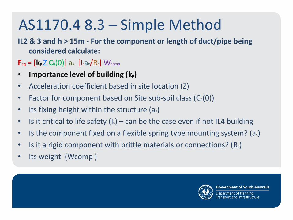
AS1170.4 8.3 – Simple Method IL2 & 3 and h > 15m - For the component or length of duct/pipe being
considered calculate:
Feq = [kp Z Ch(0)] ax [Icac/Rc] Wcomp
• Importance level of building (kp)
• Acceleration coefficient based in site location (Z)
• Factor for component based on Site sub-soil class (Ch(0))
• Its fixing height within the structure (ax)
• Is it critical to life safety (Ic) – can be the case even if not IL4 building
• Is the component fixed on a flexible spring type mounting system? (ac)
• Is it a rigid component with brittle materials or connections? (Rc)
• Its weight (Wcomp )
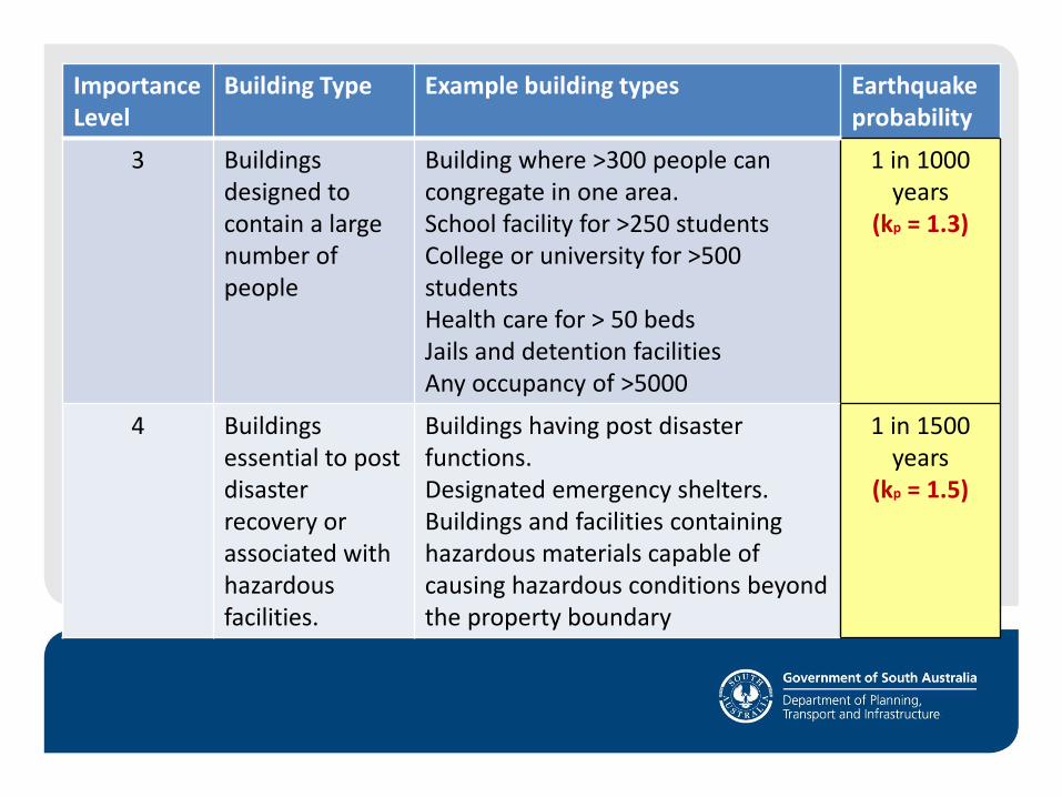
Importance Level
Building Type Example building types Earthquake probability
3 Buildings designed to contain a large number of people
Building where >300 people can congregate in one area. School facility for >250 students College or university for >500 students Health care for > 50 beds Jails and detention facilities Any occupancy of >5000
1 in 1000 years
(kp = 1.3)
4 Buildings essential to post disaster recovery or associated with hazardous facilities.
Buildings having post disaster functions. Designated emergency shelters. Buildings and facilities containing hazardous materials capable of causing hazardous conditions beyond the property boundary
1 in 1500 years
(kp = 1.5)
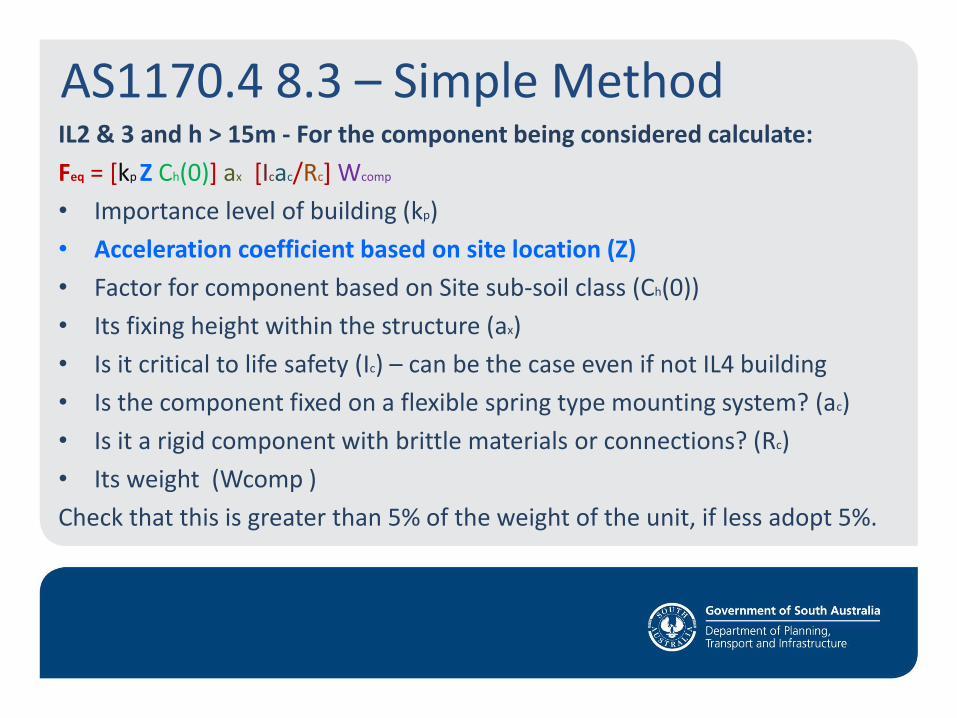
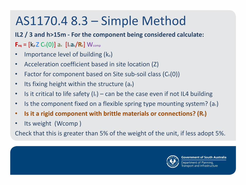
AS1170.4 8.3 – Simple Method IL2 & 3 and h > 15m - For the component being considered calculate:
Feq = [kp Z Ch(0)] ax [Icac/Rc] Wcomp
• Importance level of building (kp)
• Acceleration coefficient based on site location (Z)
• Factor for component based on Site sub-soil class (Ch(0))
• Its fixing height within the structure (ax)
• Is it critical to life safety (Ic) – can be the case even if not IL4 building
• Is the component fixed on a flexible spring type mounting system? (ac)
• Is it a rigid component with brittle materials or connections? (Rc)
• Its weight (Wcomp )
Check that this is greater than 5% of the weight of the unit, if less adopt 5%.
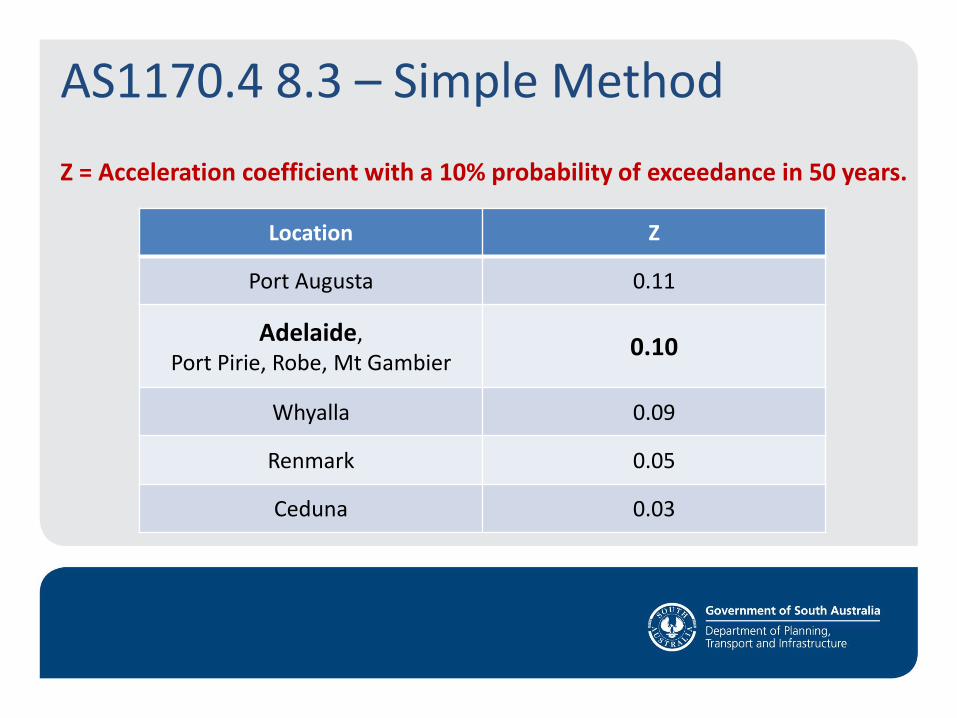
Z = Acceleration coefficient with a 10% probability of exceedance in 50 years.
Location Z
Port Augusta 0.11
Adelaide, Port Pirie, Robe, Mt Gambier
0.10
Whyalla 0.09
Renmark 0.05
Ceduna 0.03
AS1170.4 8.3 – Simple Method

AS1170.4 8.3 – Simple Method IL2 / 3 and h > 15m - For the component being considered calculate:
Feq = [kp Z Ch(0)] ax [Icac/Rc] Wcomp
• Importance level of building (kp)
• Acceleration coefficient based in site location (Z)
• Factor for component based on Site sub-soil class (Ch(0))
• Its fixing height within the structure (ax)
• Is it critical to life safety (Ic) – can be the case even if not IL4 building
• Is the component fixed on a flexible spring type mounting system? (ac)
• Is it a rigid component with brittle materials or connections? (Rc)
• Its weight (Wcomp )
Check that this is greater than 5% of the weight of the unit, if less adopt 5%.

Identify the soil at the site (Geotechnical Engineering advice)
Site sub-soil class Description Ch(0)
Class A Strong rock 0.8
Class B Rock 1.0
Class C Shallow soil 1.3
Class D Deep soil 1.1
Class E Very soft soil 1.1
AS1170.4 8.3 – Simple Method
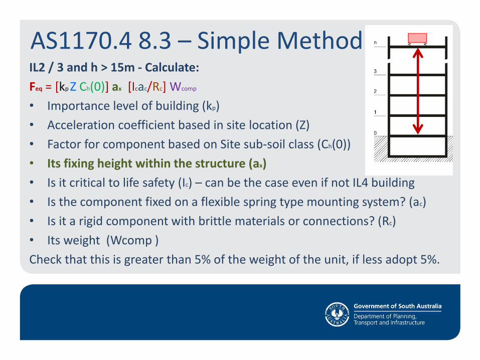
AS1170.4 8.3 – Simple Method IL2 / 3 and h > 15m - Calculate:
Feq = [kp Z Ch(0)] ax [Icac/Rc] Wcomp
• Importance level of building (kp)
• Acceleration coefficient based in site location (Z)
• Factor for component based on Site sub-soil class (Ch(0))
• Its fixing height within the structure (ax)
• Is it critical to life safety (Ic) – can be the case even if not IL4 building
• Is the component fixed on a flexible spring type mounting system? (ac)
• Is it a rigid component with brittle materials or connections? (Rc)
• Its weight (Wcomp )
Check that this is greater than 5% of the weight of the unit, if less adopt 5%.

AS1170.4 8.3 – Simple Method IL2 / 3 and h>15m - For the component being considered calculate:
Feq = [kp Z Ch(0)] ax [Icac/Rc] Wcomp
• Importance level of building (kp)
• Acceleration coefficient based in site location (Z)
• Factor for component based on Site sub-soil class (Ch(0))
• Its fixing height within the structure (ax)
• Importance factor, is it critical to life safety (Ic) – even if not IL4 building
• Is the component fixed on a flexible spring type mounting system? (ac)
• Is it a rigid component with brittle materials or connections? (Rc)
• Its weight (Wcomp )
Check that this is greater than 5% of the weight of the unit, if less adopt 5%.
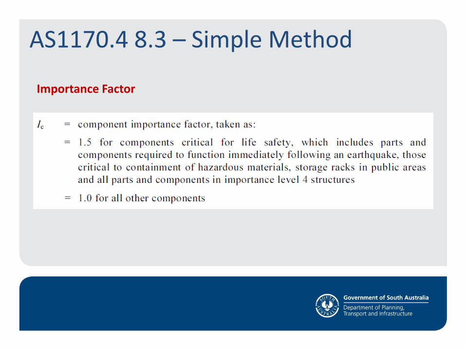
Importance Factor
AS1170.4 8.3 – Simple Method
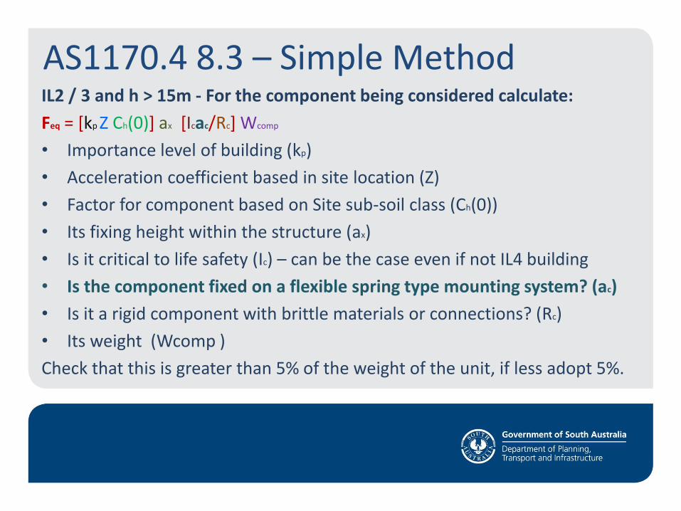
AS1170.4 8.3 – Simple Method IL2 / 3 and h > 15m - For the component being considered calculate:
Feq = [kp Z Ch(0)] ax [Icac/Rc] Wcomp
• Importance level of building (kp)
• Acceleration coefficient based in site location (Z)
• Factor for component based on Site sub-soil class (Ch(0))
• Its fixing height within the structure (ax)
• Is it critical to life safety (Ic) – can be the case even if not IL4 building
• Is the component fixed on a flexible spring type mounting system? (ac)
• Is it a rigid component with brittle materials or connections? (Rc)
• Its weight (Wcomp )
Check that this is greater than 5% of the weight of the unit, if less adopt 5%.
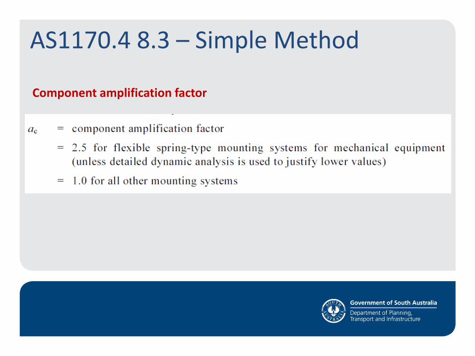
Component amplification factor
AS1170.4 8.3 – Simple Method
AS1170.4 8.3 – Simple Method IL2 / 3 and h>15m - For the component being considered calculate:
Feq = [kp Z Ch(0)] ax [Icac/Rc] Wcomp
• Importance level of building (kp)
• Acceleration coefficient based in site location (Z)
• Factor for component based on Site sub-soil class (Ch(0))
• Its fixing height within the structure (ax)
• Is it critical to life safety (Ic) – can be the case even if not IL4 building
• Is the component fixed on a flexible spring type mounting system? (ac)
• Is it a rigid component with brittle materials or connections? (Rc)
• Its weight (Wcomp )
Check that this is greater than 5% of the weight of the unit, if less adopt 5%.
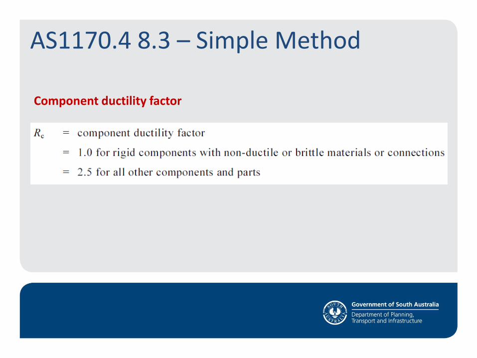
Component ductility factor
AS1170.4 8.3 – Simple Method
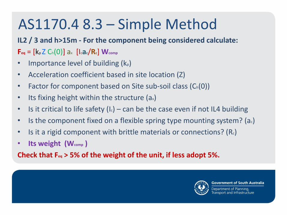
AS1170.4 8.3 – Simple Method IL2 / 3 and h>15m - For the component being considered calculate:
Feq = [kp Z Ch(0)] ax [Icac/Rc] Wcomp
• Importance level of building (kp)
• Acceleration coefficient based in site location (Z)
• Factor for component based on Site sub-soil class (Ch(0))
• Its fixing height within the structure (ax)
• Is it critical to life safety (Ic) – can be the case even if not IL4 building
• Is the component fixed on a flexible spring type mounting system? (ac)
• Is it a rigid component with brittle materials or connections? (Rc)
• Its weight (Wcomp )
Check that Feq > 5% of the weight of the unit, if less adopt 5%.
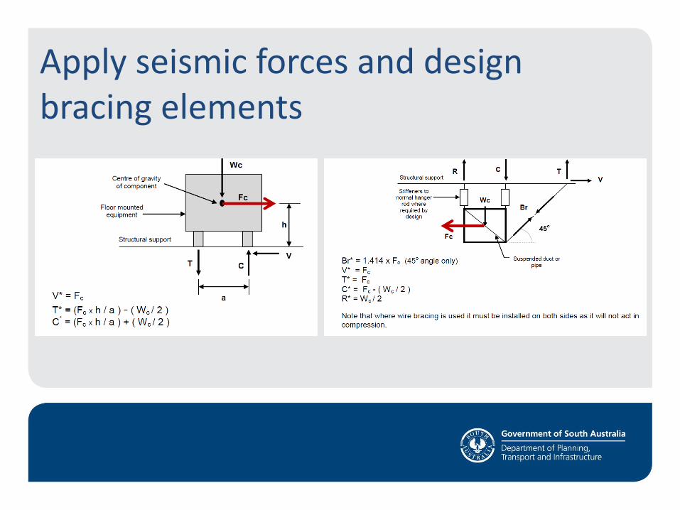
Apply seismic forces and design bracing elements
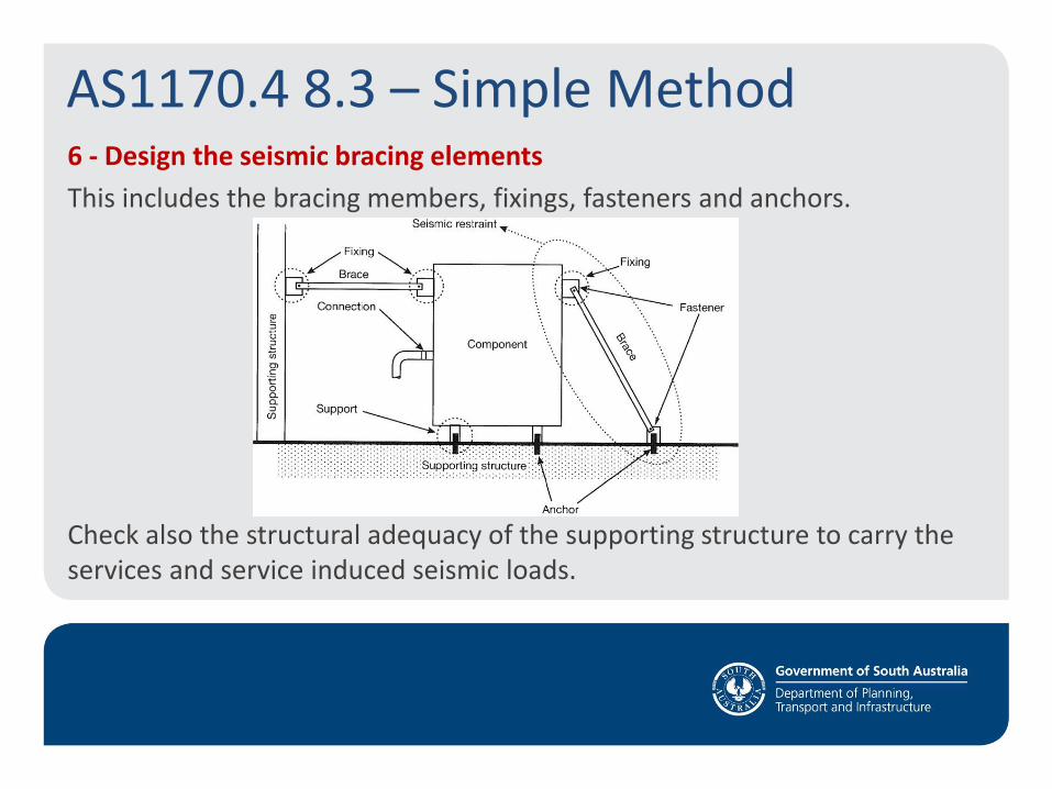
6 - Design the seismic bracing elements
This includes the bracing members, fixings, fasteners and anchors.
Check also the structural adequacy of the supporting structure to carry the services and service induced seismic loads.
AS1170.4 8.3 – Simple Method

Design considerations • Type of bracing
• Type of anchors
• Compression in suspension rods
• Interaction with ceilings
• Transmission of vibration to structure
• Thermal movements
• Services crossing structural separations.
• Service plinth reinforcement and dowels to structural slab.
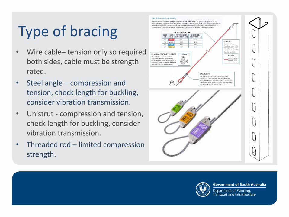
Type of bracing • Wire cable– tension only so required
both sides, cable must be strength rated.
• Steel angle – compression and tension, check length for buckling, consider vibration transmission.
• Unistrut - compression and tension, check length for buckling, consider vibration transmission.
• Threaded rod – limited compression strength.
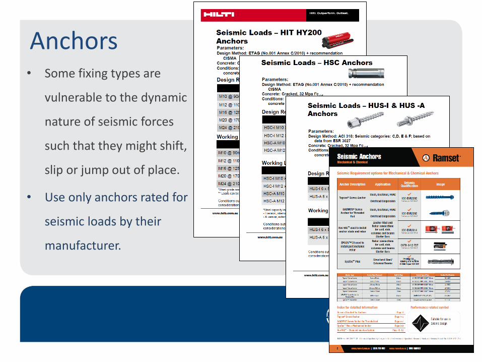
Anchors • Some fixing types are
vulnerable to the dynamic
nature of seismic forces
such that they might shift,
slip or jump out of place.
• Use only anchors rated for
seismic loads by their
manufacturer.
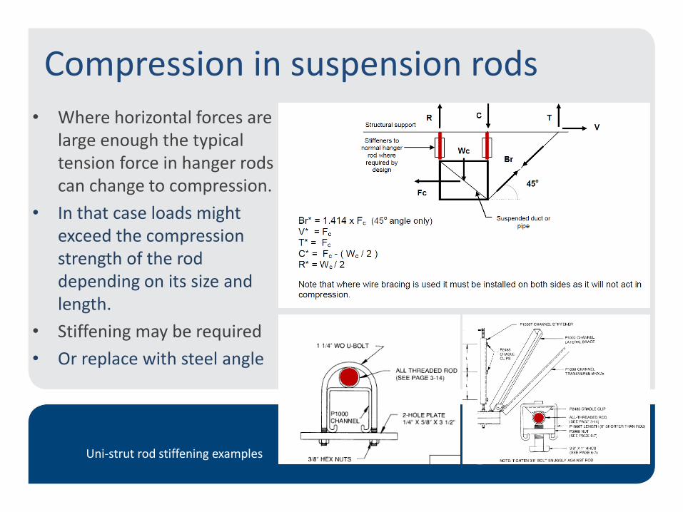
Compression in suspension rods
• Where horizontal forces are large enough the typical tension force in hanger rods can change to compression.
• In that case loads might exceed the compression strength of the rod depending on its size and length.
• Stiffening may be required
• Or replace with steel angle
Uni-strut rod stiffening examples.
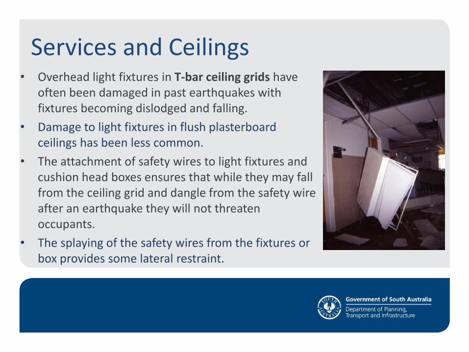
Services and Ceilings • Overhead light fixtures in T-bar ceiling grids have
often been damaged in past earthquakes with fixtures becoming dislodged and falling.
• Damage to light fixtures in flush plasterboard ceilings has been less common.
• The attachment of safety wires to light fixtures and cushion head boxes ensures that while they may fall from the ceiling grid and dangle from the safety wire after an earthquake they will not threaten occupants.
• The splaying of the safety wires from the fixtures or box provides some lateral restraint.
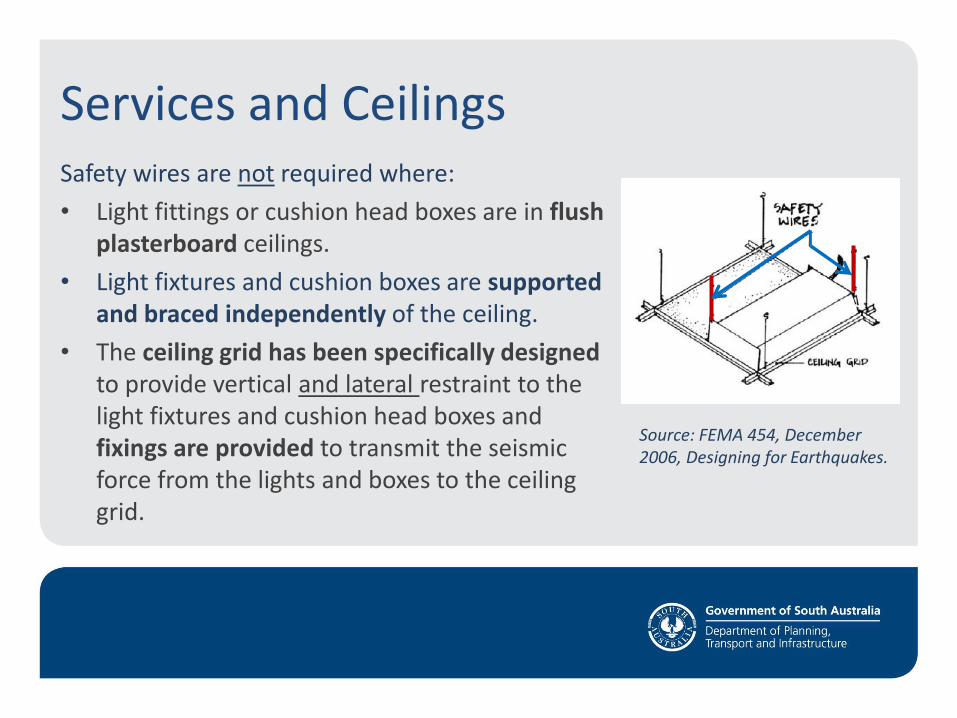
Safety wires are not required where:
• Light fittings or cushion head boxes are in flush plasterboard ceilings.
• Light fixtures and cushion boxes are supported and braced independently of the ceiling.
• The ceiling grid has been specifically designed to provide vertical and lateral restraint to the light fixtures and cushion head boxes and fixings are provided to transmit the seismic force from the lights and boxes to the ceiling grid.
Services and Ceilings
Source: FEMA 454, December 2006, Designing for Earthquakes.
Services in T-bar ceilings ??
Services and Ceilings
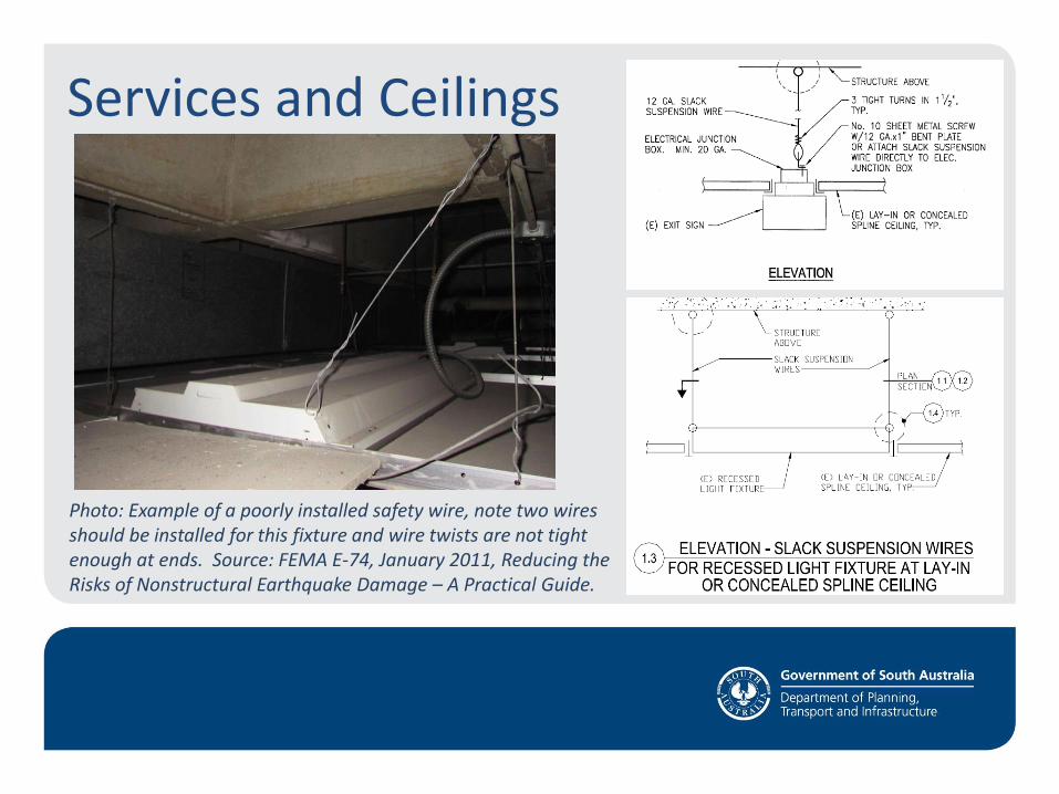
Photo: Example of a poorly installed safety wire, note two wires should be installed for this fixture and wire twists are not tight enough at ends. Source: FEMA E-74, January 2011, Reducing the Risks of Nonstructural Earthquake Damage – A Practical Guide.
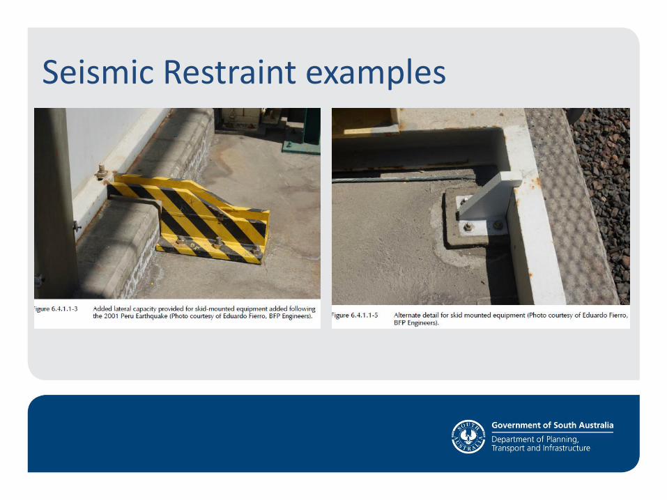
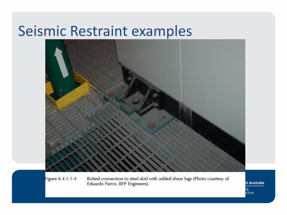
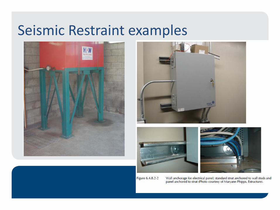
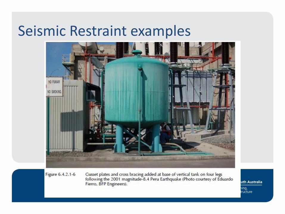
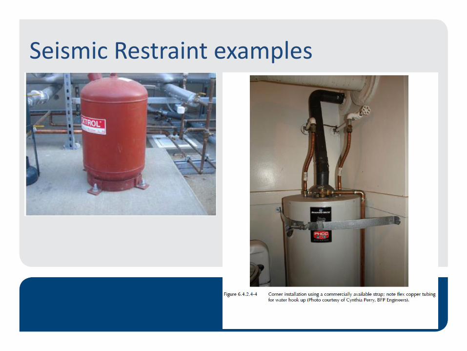
Seismic Restraint Examples
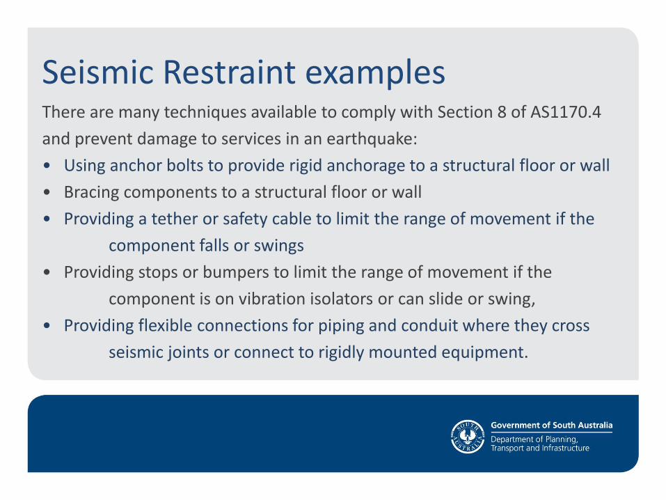
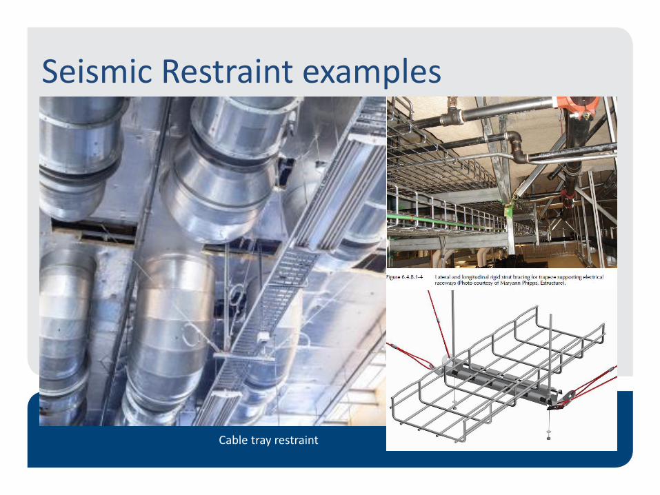
Seismic Restraint examples There are many techniques available to comply with Section 8 of AS1170.4
and prevent damage to services in an earthquake:
• Using anchor bolts to provide rigid anchorage to a structural floor or wall
• Bracing components to a structural floor or wall
• Providing a tether or safety cable to limit the range of movement if the
component falls or swings
• Providing stops or bumpers to limit the range of movement if the
component is on vibration isolators or can slide or swing,
• Providing flexible connections for piping and conduit where they cross
seismic joints or connect to rigidly mounted equipment.
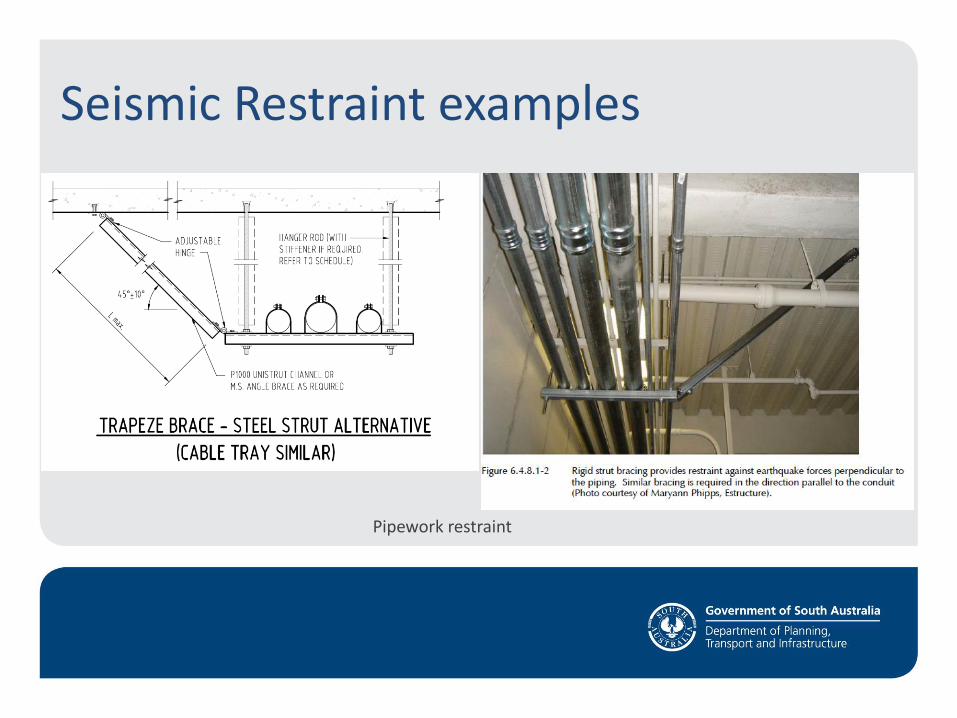
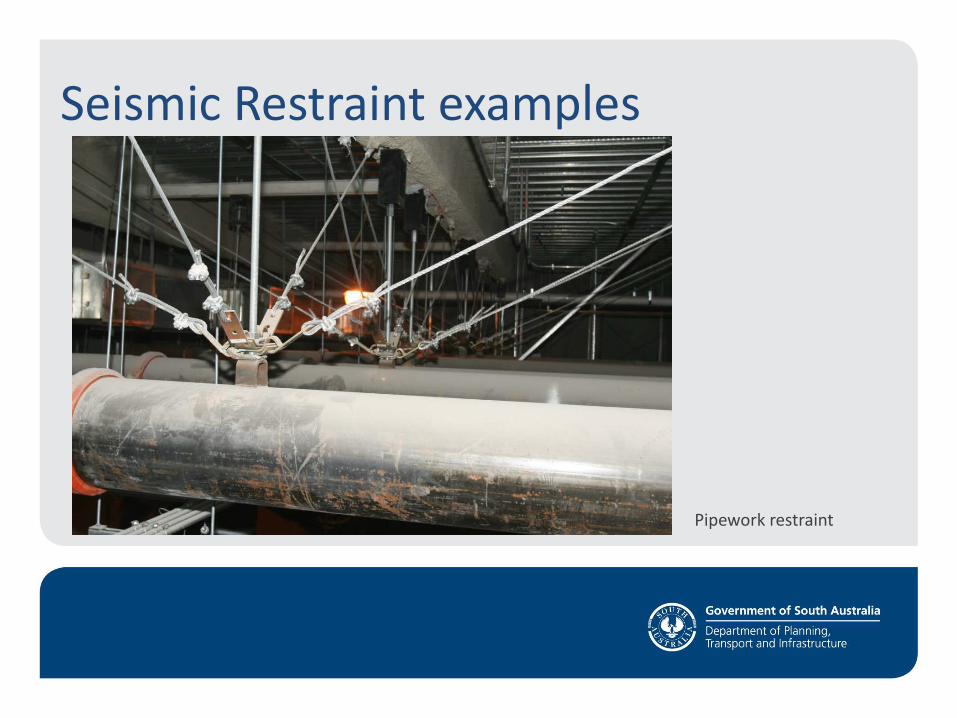
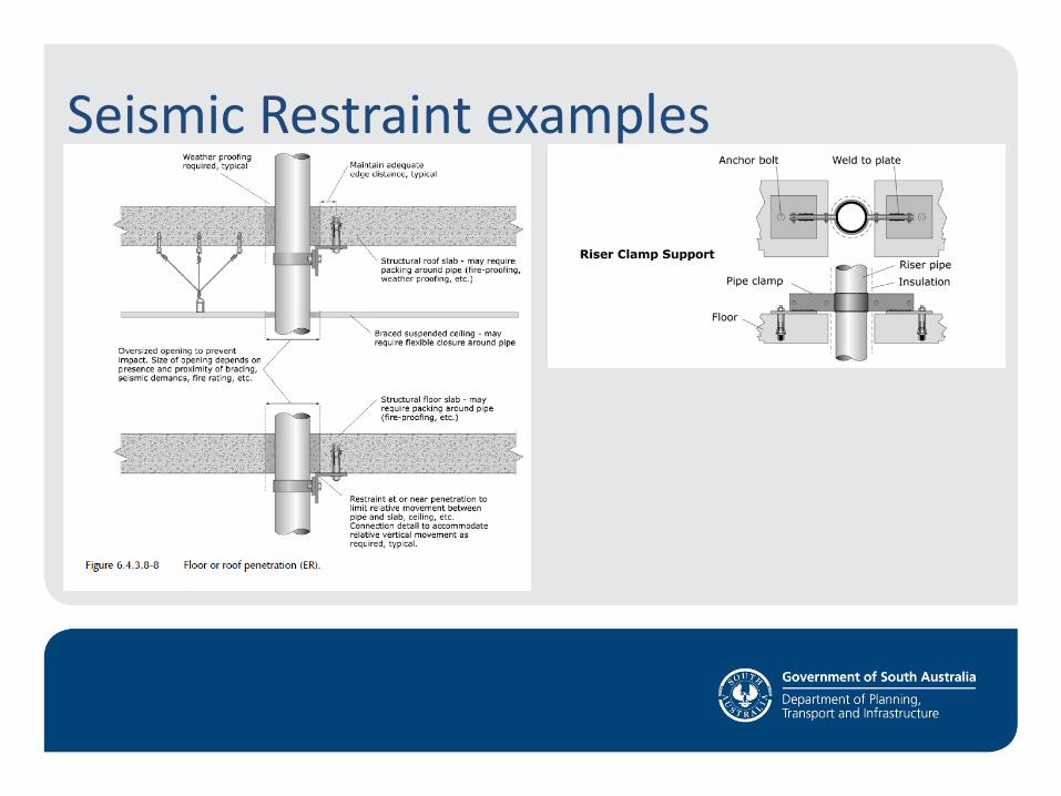
Seismic Restraint examples
Pipework restraint
Seismic Restraint examples
Pipework restraint
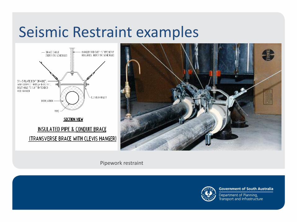
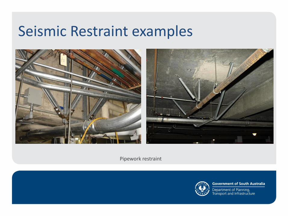
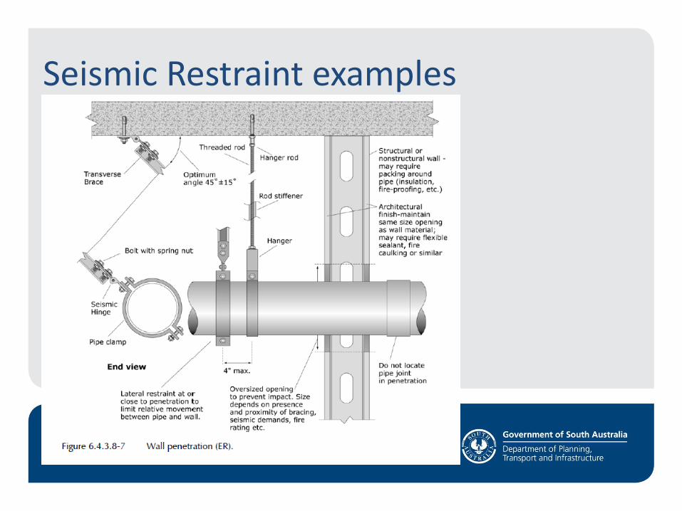
Seismic Restraint examples
Pipework restraint
Seismic Restraint examples
Pipework restraint
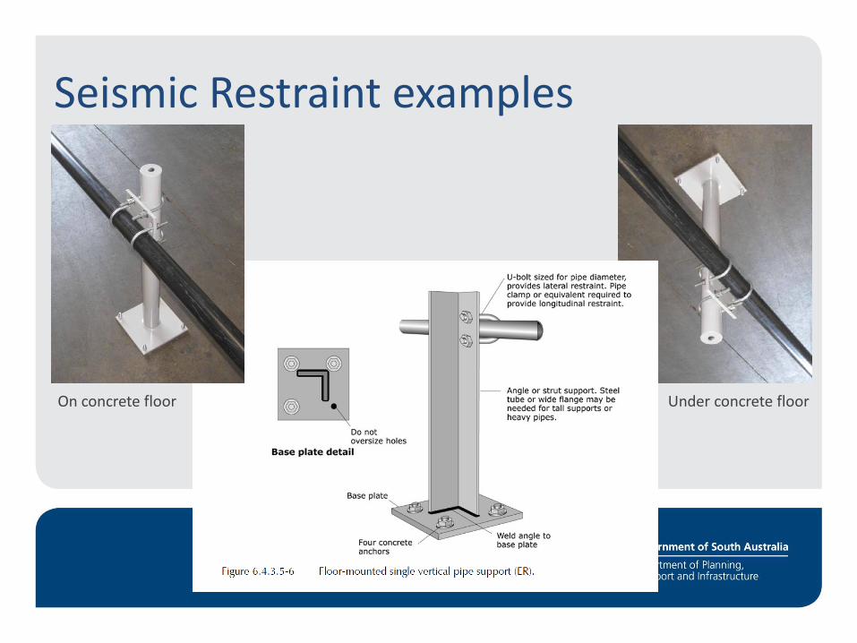
Seismic Restraint examples
Under concrete floor On concrete floor
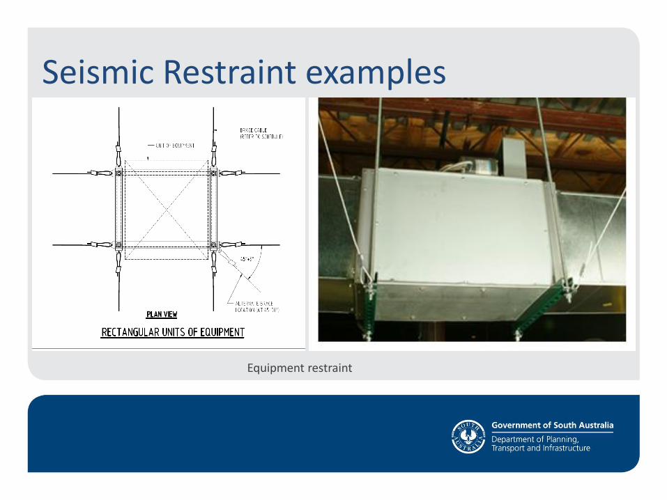
Seismic Restraint examples
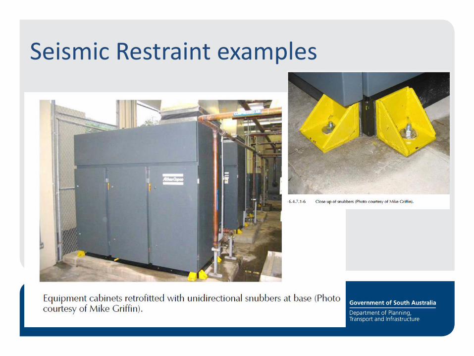
Equipment restraint
Seismic Restraint examples
Cable tray restraint
Seismic Restraint examples
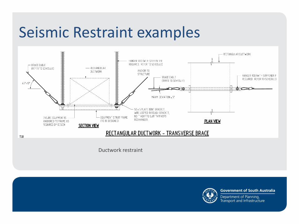
Ductwork restraint
Restraint examples
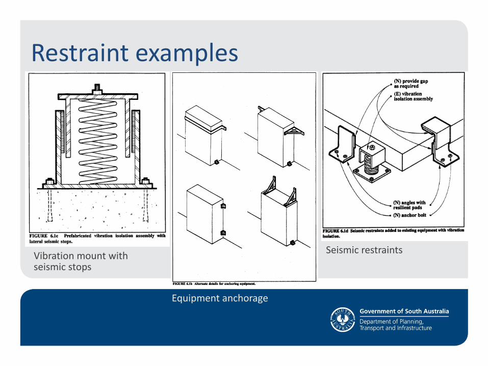
Vibration mount with seismic stops
Equipment anchorage
Seismic restraints
Seismic Restraint examples
Stud wall restraint
Seismic Restraint examples
Seismic Restraint examples
Stud wall restraint
Seismic Restraint examples
Stud wall restraint
Seismic Restraint examples
Seismic Restraint examples
Seismic Restraint examples
Seismic Restraint examples
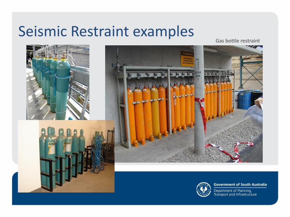
Seismic Restraint examples Gas bottle restraint
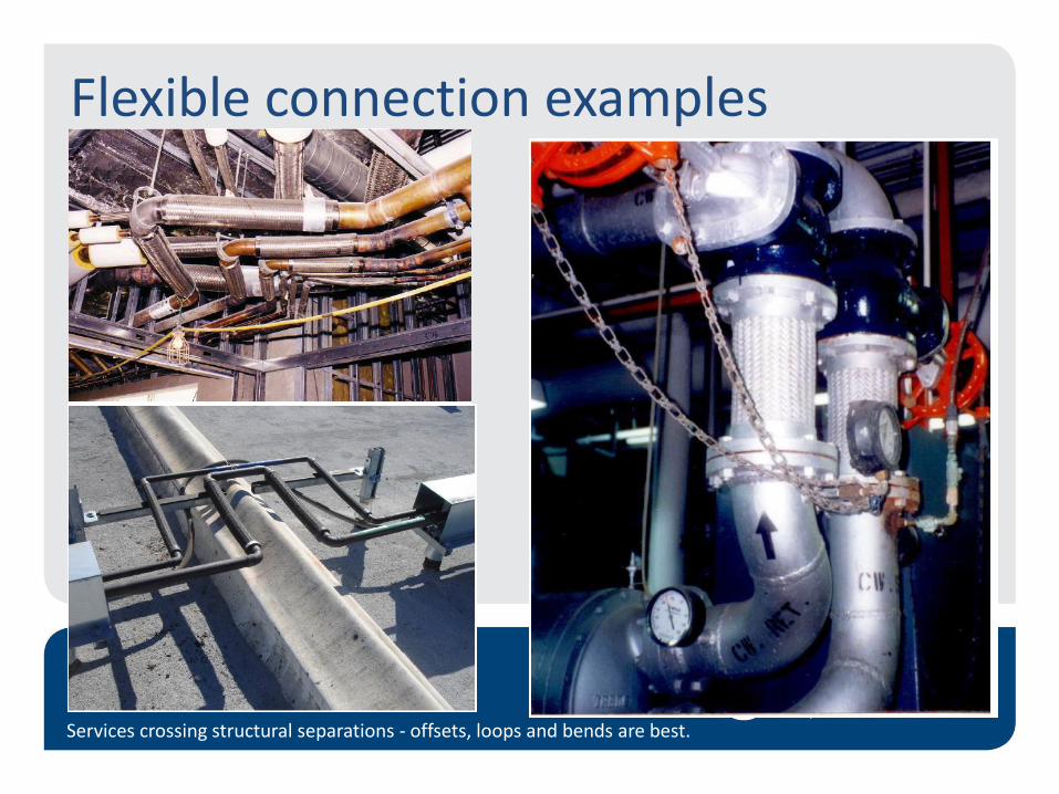
Flexible connection examples
Services crossing structural separations - offsets, loops and bends are best.
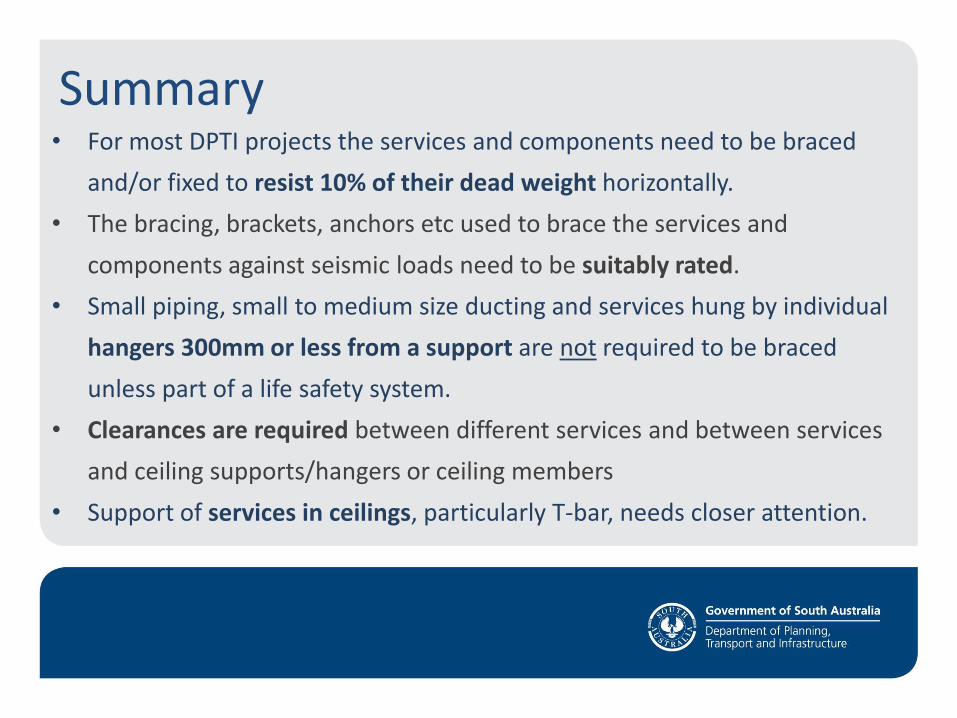
Summary • For most DPTI projects the services and components need to be braced
and/or fixed to resist 10% of their dead weight horizontally.
• The bracing, brackets, anchors etc used to brace the services and
components against seismic loads need to be suitably rated.
• Small piping, small to medium size ducting and services hung by individual
hangers 300mm or less from a support are not required to be braced
unless part of a life safety system.
• Clearances are required between different services and between services
and ceiling supports/hangers or ceiling members
• Support of services in ceilings, particularly T-bar, needs closer attention.
Conclusion Our intent is that in the near future the restraint of services to
comply with Section 8 of AS1170.4 is documented in detail on DPTI
projects prior to tender such that:
• Proper allowance is made in tenders for seismic bracing.
• Seismic bracing of services is correctly installed.
• Consultants and DPTI Inspectors know what to expect on site.
• AS1170.4 and thereby the National Construction Code is
complied with.
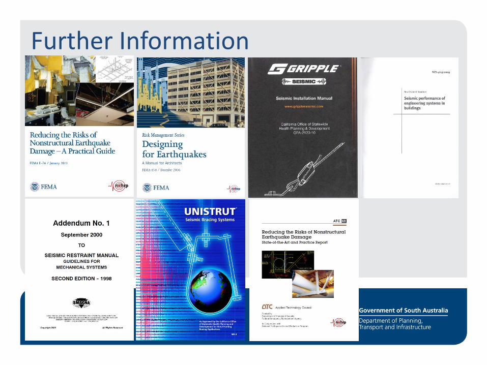
Further Information
Questions?
During an Earthquake……