seismic response analyses of rocking structural systems
TRANSCRIPT

M. Midorikawa1, T. Azuhata2, T. Ishihara2 & A. Wada3 1Building Research Institute, Japan 2National Institute for Land and Infrastructure Management, Japan 3Struct. Engrg. Research Center, Tokyo Institute of Technology, Japan
Abstract
It is pointed out that the effects of rocking vibration accompanied with up-lift motion may reduce the seismic damage of buildings subjected to severe earthquake motions. Based on these findings, we have been developing the rocking structural systems that cause the rocking vibration under appropriate control during a major earthquake motion. One of these systems has weak base plates at the bottom of each column at the first story of steel frames. When the weak base plates yield during a major earthquake motion, the frames cause the rocking vibration. In this paper, the seismic responses of the base-plate-yielding rocking systems are examined by finite element analysis. A three-story, one-by-two bay braced steel frame of a half scale is analyzed, that was previously tested by a shaking table. According to the results of the previous tests, the base plate yielding systems reduced effectively the seismic responses of steel frames. The total height of the test frame is 5.3 meters, each floor height is 1.7 to 1.8 meters, each floor plan is 3 by 4 meters, and the total weight is 15.0 tons. The yielding base plates are installed at the bottom of each column at the first story. One of the three frames in the test direction is modelled in the analysis. The base plates and the columns of the first story are modelled as shell elements. The columns and girders at the second and third stories are modelled as beam elements, and the bracing members as truss elements. The earthquake ground motion is the record of the 1940 El Centro NS component whose time scale is shortened to 1/√2. From the analytical results, it is concluded that the seismic responses of the base-plate-yielding rocking systems are appropriately simulated comparing with the experimental results obtained from the previous shaking table tests. Keywords: seismic response, dynamic analysis, finite element method, seismic response reduction, rocking vibration, up-lift, steel frame, base plate, yielding.
© 2005 WIT Press WIT Transactions on The Built Environment, Vol 81, www.witpress.com, ISSN 1743-3509 (on-line)
Earthquake Resistant Engineering Structures V 333
the finite element method
Seismic response analyses of rocking structural systems with yielding base plates by

1 Introduction
It has been pointed out that the effects of rocking vibration accompanied with up-lift motion may reduce the seismic damage of buildings subjected to strong earthquake ground motions [1, 2]. Based on these experiences, the rocking structural systems have been developed that cause rocking vibration under appropriate control during major earthquake ground motions [3, 4]. One of the rocking structural systems under development has yielding base plates at the bottom of each steel column of the lowest story. When the weak base plates yield due to tension of column during a strong earthquake ground motion, a building structure causes rocking vibration. The basic idea of the base plate yielding systems is illustrated in Fig. 1. In this paper, the seismic responses of the base-plate-yielding rocking systems are examined by the finite element analysis [5] comparing with the experimental results obtained from the previous shaking table tests [3, 4].
2 Test frame and experimental procedures
The experimental results of the previous shaking table tests on the base-plate-yielding rocking systems are briefly summarized below, whose details are published elsewhere [3, 4].
Figure 1: Structural rocking system with yielding base plates.
A three-story, one-by-two bay braced steel frame of two-thirds scale was tested on a large shaking table in Tsukuba. The test frame is composed of moment-resisting steel frames and structural components such as yielding base plates installed to the bases of the columns at the first story and bracing members of high-strength prestressing steel bar as shown in Fig. 2. The total height of the frame is 5.3 meters, each floor height is 1.7 meters at the first story and 1.8 meters at the second and third stories, each floor plan is 3 by 4 meters, and
A base plate yieldsdue to tension in column.
© 2005 WIT Press WIT Transactions on The Built Environment, Vol 81, www.witpress.com, ISSN 1743-3509 (on-line)
334 Earthquake Resistant Engineering Structures V
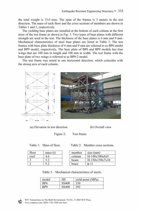
the total weight is 15.0 tons. The span of the frames is 3 meters in the test direction. The mass of each floor and the cross sections of members are shown in Tables 1 and 2, respectively. The yielding base plates are installed at the bottom of each column at the first story of the test frame as shown in Fig. 3. Two types of base plates with different strength are used in the test. The thickness of the base plates is 6 mm and 9 mm. Mechanical characteristics of steel base plates are listed in Table 3. The test frames with base plate thickness of 6 mm and 9 mm are referred to as BP6 model and BP9 model, respectively. The base plate of BP6 and BP9 models has four wings that are 100 mm in length and 100 mm in width. The test frame with the base plate of two wings is referred to as BP9-2 model. The test frame was tested in one horizontal direction, which coincides with the strong axis of each column.
(a) Elevation in test direction (b) Overall view
Figure 2: Test frame.
Table 1: Mass of floor.
floor mass (t) roof 4.6 3 5.2 2 5.2
Table 2: Member cross sections.
member size (mm) column H-148x100x6x9 beam H-150x150x7x10 brace φ-11
Table 3: Mechanical characteristics of steels.
model JIS yield point (MPa) BP6 SS400 330 BP9 SS400 292
© 2005 WIT Press WIT Transactions on The Built Environment, Vol 81, www.witpress.com, ISSN 1743-3509 (on-line)
Earthquake Resistant Engineering Structures V 335
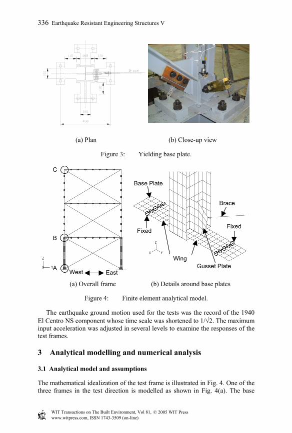
(a) Plan (b) Close-up view
Figure 3: Yielding base plate.
(a) Overall frame (b) Details around base plates
Figure 4: Finite element analytical model.
The earthquake ground motion used for the tests was the record of the 1940 El Centro NS component whose time scale was shortened to 1/√2. The maximum input acceleration was adjusted in several levels to examine the responses of the test frames.
3 Analytical modelling and numerical analysis
3.1 Analytical model and assumptions
The mathematical idealization of the test frame is illustrated in Fig. 4. One of the three frames in the test direction is modelled as shown in Fig. 4(a). The base
X Y
Z
B
A EastWest
C
X Y
Z
Fixed
Gusset Plate
Brace
Wing
Fixed
Base Plate
© 2005 WIT Press WIT Transactions on The Built Environment, Vol 81, www.witpress.com, ISSN 1743-3509 (on-line)
336 Earthquake Resistant Engineering Structures V
plates and the columns of the first story are modelled as shell elements as shown in Fig. 4(b). The columns and girders at the second and third stories are modeled as beam elements, and the bracing members as truss elements. The base plate is assumed to be elasto-plastic materials considering the finite deformation, for which the kinematic hardening rule is applied and the shear strain energy theory is used as the yield condition. The other elements are assumed to be elastic. The bracing members are assumed to resist only tensile force, in which the initial strain of 1050 µ is applied. The foundation beam is assumed to be rigid. The nodal points along the edge of the restraint steel plate are fixed as shown in Fig. 4(b). The rigid connection is assumed between shell and beam elements at Point B in Fig. 4(a). The out-of-plane displacements are restrained at the beam-to-column connections at the roof level.
3.2 Numerical analysis
The masses of the frame model based on the actual dead loads of the test frame are lumped at each nodal point. The vertical dead loads that correspond to the lamped masses are applied statically to each node of the frame model before starting the dynamic response analysis. It is assumed that the viscous damping results from the initial stiffness-dependent effects. The critical damping ratio of 0.5% is introduced to the first mode in bending, whose value is compatible with the shaking table test results of the test frame [3, 4]. The numerical time integration in the analysis is the combined use of the Newmark method with integration constant equal to 1/4 based on the constant acceleration and the Newton-Raphson method of equilibrium iteration within the time step of 0.001 second. The measured acceleration record on the shaking table in the tests [3, 4] is used in the dynamic response analysis of the frame model, which is the record of the 1940 El Centro NS component whose time scale is reduced to 1/√2. The duration time is six seconds in the analysis.
4 Analytical results and discussion
The analytical results in the case of BP9-2 model (base plate of two wings) subjected to the maximum acceleration of 6.02 m/s2 in the shaking table tests [3, 4] are presented and discussed herein.
4.1 Mode shapes and natural periods
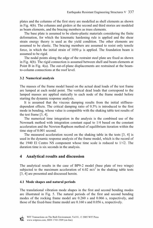
The translational vibration mode shapes in the first and second bending modes are illustrated in Fig. 5. The natural periods of the first and second bending modes of the rocking frame model are 0.260 s and 0.066 s, respectively, and those of the fixed-base frame model are 0.160 s and 0.056 s, respectively.
© 2005 WIT Press WIT Transactions on The Built Environment, Vol 81, www.witpress.com, ISSN 1743-3509 (on-line)
Earthquake Resistant Engineering Structures V 337
(a) First bending mode (b) Second bending mode
Figure 5: Translational vibration mode shapes in bending.
4.2 Time history responses
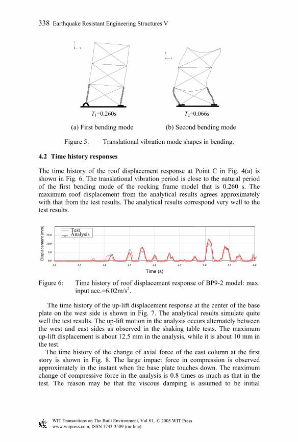
The time history of the roof displacement response at Point C in Fig. 4(a) is shown in Fig. 6. The translational vibration period is close to the natural period of the first bending mode of the rocking frame model that is 0.260 s. The maximum roof displacement from the analytical results agrees approximately with that from the test results. The analytical results correspond very well to the test results.
Figure 6: Time history of roof displacement response of BP9-2 model: max. input acc.=6.02m/s2.
The time history of the up-lift displacement response at the center of the base plate on the west side is shown in Fig. 7. The analytical results simulate quite well the test results. The up-lift motion in the analysis occurs alternately between the west and east sides as observed in the shaking table tests. The maximum up-lift displacement is about 12.5 mm in the analysis, while it is about 10 mm in the test. The time history of the change of axial force of the east column at the first story is shown in Fig. 8. The large impact force in compression is observed approximately in the instant when the base plate touches down. The maximum change of compressive force in the analysis is 0.8 times as much as that in the test. The reason may be that the viscous damping is assumed to be initial
X Y
Z
X Y
Z
T1=0.260s T2=0.066s
Time (s)
Dis
plac
emen
t (m
m) West Base Plaate 浮き上がり変位(試験体モデル)
0.0
5.0
10.0
15.0
20.0
2.0 2.5 3.0 3.5 4.0 4.5 5.0 5.5 6.0
実験値
解析結果
(mm)Test Analysis
© 2005 WIT Press WIT Transactions on The Built Environment, Vol 81, www.witpress.com, ISSN 1743-3509 (on-line)
338 Earthquake Resistant Engineering Structures V
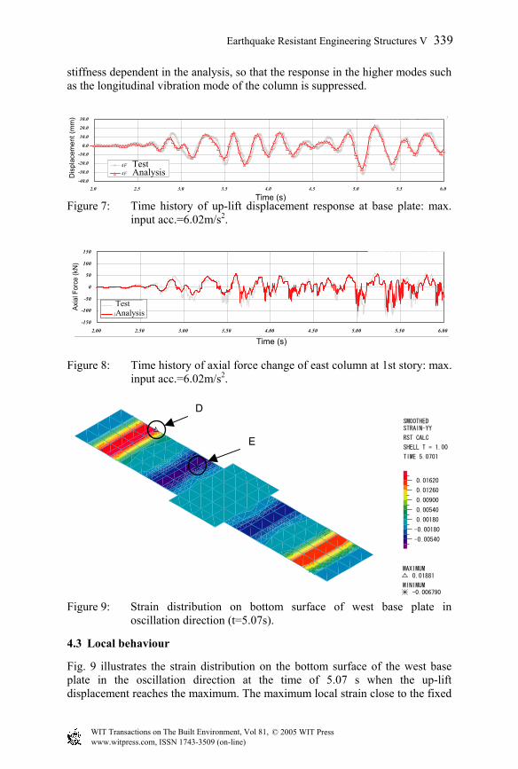
stiffness dependent in the analysis, so that the response in the higher modes such as the longitudinal vibration mode of the column is suppressed.
Figure 7: Time history of up-lift displacement response at base plate: max. input acc.=6.02m/s2.
Figure 8: Time history of axial force change of east column at 1st story: max. input acc.=6.02m/s2.
Figure 9: Strain distribution on bottom surface of west base plate in oscillation direction (t=5.07s).
4.3 Local behaviour
Fig. 9 illustrates the strain distribution on the bottom surface of the west base plate in the oscillation direction at the time of 5.07 s when the up-lift displacement reaches the maximum. The maximum local strain close to the fixed
SMOOTHEDSTRAIN-YY
RST CALC
SHELL T = 1.00
TIME 5.0701
0.01620
0.01260
0.00900
0.00540
0.00180
-0.00180
-0.00540
MAXIMUM0.01881
MINIMUM-0.006790
D
E
4F水平変位(試験体モデル)
-40.0
-30.0
-20.0
-10.0
0.0
10.0
20.0
30.0
2.0 2.5 3.0 3.5 4.0 4.5 5.0 5.5 6.0time(sec)
disp
lace
men
t(mm
)
4F水平変位(実験値)
4F水平変位 ( 解析値)Dis
plac
emen
t (m
m)
Test Analysis
Time (s)
Time (s)
東側柱軸力(試験体モデル)
-150
-100
-50
0
50
100
150
2.00 2.50 3.00 3.50 4.00 4.50 5.00 5.50 6.00time(sec)
Axi
al F
orce
(kN
)
実験値
East柱軸力
Axia
l For
ce (k
N)
Test Analysis
© 2005 WIT Press WIT Transactions on The Built Environment, Vol 81, www.witpress.com, ISSN 1743-3509 (on-line)
Earthquake Resistant Engineering Structures V 339
nodal points of the base plate, at Point D in Fig. 9, goes up to 18800 µ in tension, which exceeds the yield point of steel but is far away from the fracture strain. The peak local strain near the column end of the base plate, at Point E in Fig. 9, attains to 6800 µ in compression.
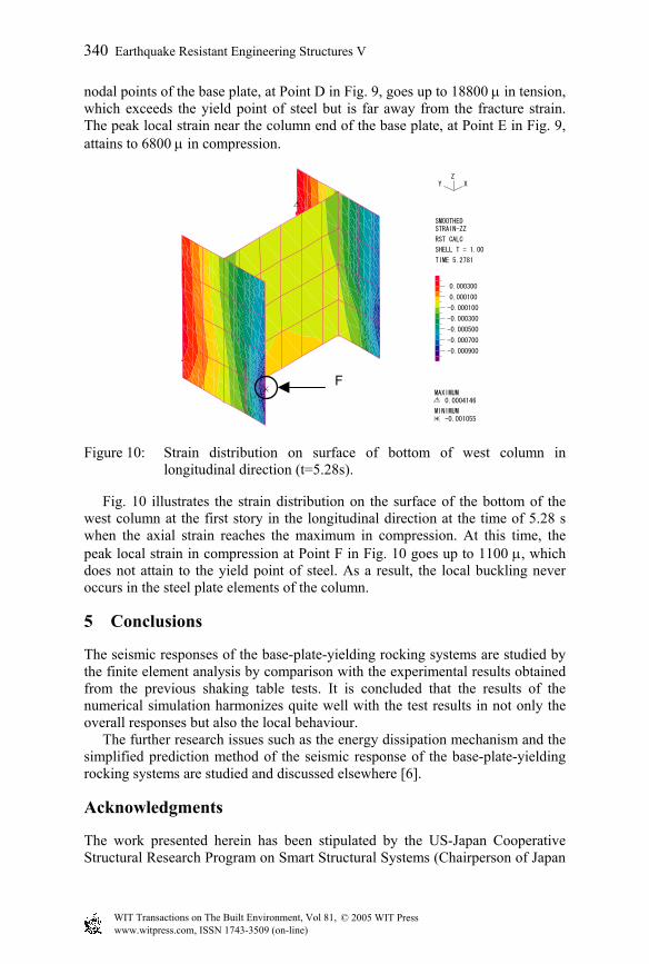
Figure 10: Strain distribution on surface of bottom of west column in longitudinal direction (t=5.28s).
Fig. 10 illustrates the strain distribution on the surface of the bottom of the west column at the first story in the longitudinal direction at the time of 5.28 s when the axial strain reaches the maximum in compression. At this time, the peak local strain in compression at Point F in Fig. 10 goes up to 1100 µ, which does not attain to the yield point of steel. As a result, the local buckling never occurs in the steel plate elements of the column.
5 Conclusions
The seismic responses of the base-plate-yielding rocking systems are studied by the finite element analysis by comparison with the experimental results obtained from the previous shaking table tests. It is concluded that the results of the numerical simulation harmonizes quite well with the test results in not only the overall responses but also the local behaviour. The further research issues such as the energy dissipation mechanism and the simplified prediction method of the seismic response of the base-plate-yielding rocking systems are studied and discussed elsewhere [6].
Acknowledgments
The work presented herein has been stipulated by the US-Japan Cooperative Structural Research Program on Smart Structural Systems (Chairperson of Japan
XYZ
SMOOTHEDSTRAIN-ZZ
RST CALC
SHELL T = 1.00
TIME 5.2781
0.000300
0.000100
-0.000100
-0.000300
-0.000500
-0.000700
-0.000900
MAXIMUM0.0004146
MINIMUM-0.001055
F
© 2005 WIT Press WIT Transactions on The Built Environment, Vol 81, www.witpress.com, ISSN 1743-3509 (on-line)
340 Earthquake Resistant Engineering Structures V
side: Prof. S. Otani, University of Tokyo at that time). The authors would like to acknowledge all project members for their useful advice and suggestions. The authors also express their gratitude to Ms. Y. Takeuchi and Mr. M. Kawakami of Kozo Keikaku Engineering Inc. for their excellent support in the analysis. Part of this work is supported by the Ministry of Education, Culture, Sports, Science and Technology (MEXT) of Japan under Grant-in-Aid for Scientific Research.
References
[1] Rutenberg, A., Jennings, P. C. & Housner, G. W., The response of Veterans Hospital Building 41 in the San Fernando Earthquake. Earthquake Engineering and Structural Dynamics, 10(3), pp. 359-379, 1982.
[2] Hayashi, Y., Damage reduction effect due to basement uplift of buildings. J. Structural and Construction Engineering, Architectural Institute of Japan, 485, pp. 53-62, 1996 (In Japanese).
[3] Midorikawa, M., Azuhata, T., Ishihara, T. & Wada, A., Shaking table tests on rocking structural systems installed yielding base plates in steel frames. Proc. STESSA 2003 (4th International Conference on Behaviour of Steel Structures in Seismic Areas), pp. 449-454, Naples, Italy, 2003.
[4] Midorikawa, M., Azuhata, T., Ishihara, T. & Wada, A., Dynamic behaviour of steel frames with yielding base plates in uplift motion for seismic response reduction. J. Structural and Construction Engineering, Architectural Institute of Japan, 572, pp. 97-104, 2003 (in Japanese).
[5] ADINA R&D, Inc., Theory and Modelling Guide - ADINA, Report ARD 02-7, 2002.
[6] Azuhata, T., Midorikawa, M. & Ishihara, T., Energy dissipation mechanism and maximum response displacement prediction of steel frames with yielding base plates in uplift motion for seismic response reduction. J. Structural and Construction Engineering, Architectural Institute of Japan, 583, pp. 61-68, 2004 (in Japanese).
© 2005 WIT Press WIT Transactions on The Built Environment, Vol 81, www.witpress.com, ISSN 1743-3509 (on-line)
Earthquake Resistant Engineering Structures V 341