seismic reliability of chevron braced … reliability of chevron braced frames with innovative...
TRANSCRIPT
Advanced Steel Construction Vol. 5, No. 4, pp. 367-389 (2009) 367
SEISMIC RELIABILITY OF CHEVRON BRACED FRAMES WITH INNOVATIVE CONCEPT
OF BRACING MEMBERS
A. Longo, R. Montuori and V. Piluso*
Department of Civil Engineering, University of Salerno via Ponte Don Melillo, Fisciano, 84084, Italy
*(Corresponding author: E-mail: [email protected])
Received: 31 December 2007; Revised: 22 July 2008; Accepted: 28 July 2008
ABSTRACT: According to the most modern trend, performance-based seismic design is aimed at the evaluation of the seismic performance of structures in terms of mean annual frequency of exceeding a threshold level of damage, i.e. a limit state. A procedure for performance-based seismic assessment is herein briefly summarised and applied to concentrically “V” braced steel frames, designed according to different criteria. In particular, two design approaches are examined. The first one corresponds to the provisions suggested by Eurocode 8, while the second approach, proposed by the authors, is based on a rigorous application of the capacity design criteria aiming at the control of the failure mode. In addition in this work a new conception of bracing members is developed and applied with reference to V-braced frames designed according to the methodology proposed by the authors. It is well known that aiming at the safeguard of brace connections, Eurocode 8 provides a limitation to the brace slenderness. The drawback of this limitation is the oversizing of brace diagonals at the upper storeys, which prevents the development of a collapse mechanism of global type. This is the starting design issue for the conception of new bracing members. In fact, by introducing in the brace members a zone characterized by a reduction of the cross sectional area (Reduced Section Solution), it is possible to calibrate the yield strength leaving substantially unchanged the slenderness, so that the limits provided for the normalized slenderness can be still satisfied without brace oversizing. The aim of this work is to focus on the seismic performance of V-braced frames designed according to both Eurocode provisions and the proposed methodology. For the structures dimensioned according to the proposed criteria, the Reduction Section Solution is also applied with the aim to safeguard the connection without increasing the structural weight. Finally, a probabilistic approach based on the combination of probabilistic seismic hazard analysis (PSHA), probabilistic seismic demand analysis (PSDA) and probabilistic seismic capacity analysis (PSCA) is applied aiming to investigate the seismic performance of the designed structures. It is pointed out how the proposed design method leads to a very important improvement of the seismic performances with a negligible increase of the overall building cost.
Keywords: Seismic reliability; concentrically braced frames; seismic hazard; probabilistic seismic demand Analysis; structural capacity
1. INTRODUCTION Chevron braced frames exhibit a limited ductility capacity under cyclic loads. In fact, the seismic response is characterized by a substantial strength degradation because, under load reversals, the previously buckled member probably could not return in its original alignment and the member which was in tension could exceed its capacity in compression. As a consequence, both diagonal members could be in a buckled condition. In addition, when the compressed member is buckled and the tensile diagonal is yielded, a vertical action, resulting from the unbalanced brace axial forces, acts on the beam and, is transmitted to the columns increasing the axial force demand. For this reason the modeling of the post-buckling behaviour of bracing members and an appropriate evaluation of the design forces for non-dissipative members are the main issue for a rigorous application of the capacity design method. To this aim, a plastic design method for concentrically braced frames has been recently developed (Longo et al. [1]). The proposed methodology is based
The Hong Kong Institute of Steel Construction www.hkisc.org

368 Seismic Reliability of Chevron Braced Frames with Innovative Conception of Bracing Members
on a rigorous application of capacity design principles aiming at the achievement of a collapse mechanism of global type, i.e. a collapse mechanism involving all the storeys so that it is characterized by the yielding of all the tensile diagonals and the buckling of the all compressed diagonals. The main feature of the proposed methodology is that the dimensioning of beams and columns is carried out accounting for the forces, transmitted by both the tensile braces and the compressed braces according to their post-buckling behaviour, occurring when all the tensile braces are yielded (Longo et al. [1-2]). In other words, the attention is focused on the internal action distribution occurring when a global mechanism is completely developed. Preliminary investigations, based on a deterministic approach, have been carried out with reference to concentrically braced frames designed according to the proposed methodology and a comparison with the same structures dimensioned according to Eurocode 8 provisions has been also carried out (Longo et al. [1]). Such preliminary results showed that the proposed method allows to drive a better seismic response in terms of both PGA values corresponding to collapse and in terms of energy dissipation capacity. Conversely, V-braced frames designed according to Eurocode 8 exhibited soft storey problems due to the premature out of plane buckling of columns. Even though the seismic behaviour of concentrically braced frames designed according to the proposed methodology (Longo et al. [2-3]) is better than the behaviour of the same structures designed according to Eurocode 8 provisions (CEN [4]), the problem regarding the oversizing of the diagonals of upper storeys still remains. In fact, the bracing members are designed to satisfy the limitation provided by Eurocode 8 concerning the normalized slenderness ( 0.2 ). The above provision allows to safeguard the brace connections, but it leads to the oversizing of the diagonals of upper storeys preventing their yielding so that the development of a collapse mechanism of global type is undetermined. Aiming at avoiding the problems coming from the oversizing of diagonal members, the idea of the Reduced Section Solution (RSS) has been presented (Longo et al. [5], Giugliano et al. [6]). The RSS allows to avoid the oversizing of bracing members, but still satisfying the brace slenderness limitation provided by seismic codes. The idea is based on the reduction of the brace section at the member ends in order to calibrate the axial resistance to a value equal to the internal action occurring under the design seismic load combination, so that there is not any overstrength. In addition, the brace slenderness remains substantially unchanged. In order to evaluate the seismic performance obtained by means of the considered design methodologies, a probabilistic method has been adopted. The comparison between different structural solutions, such as the proposed methodology and Eurocode 8 provisions, of the same design problem is immediately understandable when it is made in terms of mean annual frequency of exceeding pre-defined limit states. Even though the methodology provides the designer with the theoretical basis to account for all the sources of uncertainty, in the present work, only the aleatory uncertainty (due to record-to-record variability) is considered. Finally, it is recognized that design solutions leading to the increase of the structural weight are likely accompanied by performance improvements. Therefore, a cost versus benefit comparison between the different design solutions is also presented.
A. Longo, R. Montuori and V. Piluso 369
2. SUMMARY OF EXAMINED DESIGN APPROACHES In the case of concentrically braced frames, dissipative zones are constituted by the brace diagonal members. Conversely, beams, columns and connections to foundation are non dissipative zones. Regarding the connections between the brace and the primary structure, the traditional design approach is based on the use of non-dissipative connections. According to the traditional philosophy of capacity design, dissipative zones have to be designed considering the internal actions occurring under the seismic load combination; conversely, non dissipative zones have to be designed considering the maximum internal actions that dissipative zones, yielded and strain-hardened, are able to transmit. The structural scheme commonly adopted for evaluating the internal actions in beams, columns and diagonals of V-braced frames (VBFs) subjected to seismic actions considers as active both the tensile and the compressed diagonals. In addition, an hinge connection is assumed between the bracing members. In the case of VBFs, Eurocode 8 (CEN [4]) provides the following limitation regarding the normalized slenderness of braces:
0.2 with y and
y
y f
E (1)
where fy is the yield stress and E is the Young modulus. The aim of this limitation is the reduction of the plastic out of plane deformation of the gusset plates, due to brace buckling, which otherwise are prone to failure due to low cycle fatigue. Regarding the design of beams and columns, Eurocode 8 provisions define for each storey an overstrength coefficient i of bracing elements:
Sdibr
Rdibri N
N
,
, (2)
where Nbr,Sdi is the design value of the brace internal axial force and Nbr,Rdi is the corresponding design resistance. Beams and columns, respectively, are designed to satisfy the following hierarchy criteria:
EbSdovGbSdSdRdb N11NMN ,,, .)( (3)
EcSdovGcSdRdc N11NN ,,, . (4)
where NRd is the buckling resistance of the element (beam or column), NSd,G is the axial force due to the non seismic loads included in the seismic load combination, NSd,E is the axial force due to the seismic loads, MSd is the bending moment due to the seismic load combination, 1.10 is the amplification coefficient accounting for strain-hardening effects, ov is an overstrength factor accounting for random variability of material properties and is the minimum value of the overstrength coefficients i:
i
n
1i
p
min with np = number of storeys (5)

370 Seismic Reliability of Chevron Braced Frames with Innovative Conception of Bracing Members
The value of ov factor is taken equal to 1.25 with the aim of including all random effects of material properties. The present work, conversely, is aimed at the evaluation of the non linear seismic response from a probabilistic point of view, but accounting only for the uncertainty due to record-to-record variability, therefore, being random material variability not included, a ov factor equal to 1.00 has been considered in the following analyses. This choice is justified considering that record to record variability of earthquake motion is the prominent source of uncertainty. The beams have to be verified accounting for the vertical action resulting from the unbalanced brace axial forces, due to the fact that the compressed diagonal is buckled when the tensile one yields. In Eurocode 8, this force is approximately evaluated according to the following relationship:
2tRdbrpb1tRdbr senNsenNV ,.,. (6)
where 1 and 2 are the angles between the diagonal axes and the beam axis (typically 1 = 2), Nbr.Rd,t is design resistance of the diagonal in tension and pb is used for the evaluation of the post buckling resistance of brace members. The suggested value is 0.3. Regarding the proposed design methodology, its aim is the evaluation of the axial forces in non dissipative members (beams and columns) occurring when all the dissipative ones (diagonals) are completely yielded. Therefore, the evaluation of these forces is made by focusing the attention on the distribution of the internal actions occurring when a collapse mechanism of global type is developed. The considered structural scheme is characterised by the column continuity as shown in Figure 1(a) where the structure is considered in a deformed configuration, showing that the collapse mechanism is governed by only one parameter: i.e. the base rotation of the structure where real hinges are located. The value corresponds to the yielding of all the diagonals in tension while the compressed ones are buckled.
hi
di
i
buckling
i
i
i
-PPU
0 +
Py
ii
Py,i
Pc( i)
+P
(a) (b) Figure 1. (a) V-Braced Frame in the Deformed Configuration Corresponding to the
Global Failure Mode; (b) Evaluation of Compression and Tension Axial Force It is assumed that the cross-sections of bracing members are known as they are designed to resist internal axial forces due to the seismic load combination (CEN [4]). For this structural typology, braces are considered acting both in tension and in compression. Therefore, as first step, the post-buckling behaviour of bracing members has to be predicted. In the present work, this step is performed according to the suggestions of Georgescu (Georgescu et al. [7]). The unknowns of the design problem are the beam and the column sections required to guarantee the yielding of all the

A. Longo, R. Montuori and V. Piluso 371
bracing members, i.e. the participation of all the storeys to the dissipation of the earthquake input energy. The axial deformation corresponding to the yielding of the bracing member of the i-th storey is given by:
E
Lf
AE
LP iy
i
iyipi
(7)
where Pyi is the yield load of the i-th diagonal, fy is the yield stress, E is the elastic modulus, Li and Ai are the length and the cross-section area of the i-th diagonal, respectively. For each storey, it is possible to define the value of the interstorey drift angle i corresponding to the yielding of the i-th bracing member by means of the following yielding condition:
piiiii d cos for ni ....1 (8)
where di is the corresponding interstorey height and i is the angle between the bracing member and the beam axis:
ii
pii d
cos for ni ....1 (9)
The value of the base rotation corresponding to the yielding of all the diagonals can be expressed as:
)(max in
1im (10) Therefore, for each storey, the value of the axial deformation occurring in the diagonal members when the collapse mechanism is completely developed, can be easily computed as:
iimi d cos (11)
The above value provides both the elongation of the diagonal in tension and the shortening of the compressed diagonal subjected to buckling. Therefore, in the collapse condition, the axial force in the tensile diagonal of the i-th storey is equal to Pyi, while the axial force in the corresponding buckled compressed diagonal can be derived according to Figure 1b. With reference to beams, the net downward force resulting from the combinations of the forces acting in the diagonals of i-th storey is equal to:
iiciiyi PP V sinsin, (12) The horizontal force transmitted by the braces to the beam is equal to:
iiciiyi PPH cos)(cos, (13)

372 Seismic Reliability of Chevron Braced Frames with Innovative Conception of Bracing Members
The unbalanced action (Vi) applied to the beam, due to the post-buckling behaviour of braces, is used both to design the beam and to evaluate the axial force in the columns, while the horizontal force Hi applied at the midspan of the beam is used only for beam design. Therefore, by focusing the attention on the distribution of the internal actions in the kinematic mechanism condition, according to the second principle of capacity design, the design value of the axial force in the non-dissipative members is computed. In particular, with reference to columns, the axial force to be considered in design is given by:
nifor 2
sinsin
nifor sin)( 2
1 sin
...,
...
...
n
1j,
1...
nGSdcnncnny
nESdc
iGSdcjjcjyj
n
ijjciESdc
NPP
N
NPPPN
(14)
where Py,j and Pc(j) are the tension and compression forces in the j-th brace respectively, while Nc.Sd.G.i is the axial force in the column due to the gravity loads acting in the seismic load combination. 3. DESIGN OF BRACING MEMBERS WITH “REDUCED SECTION SOLUTION” The idea of bracing members with reduced section solution (Figure 2) has been suggested by the need to overcome the drawbacks coming from the design of conventional concentrically braced frames. In fact, the use of code suggested design criteria and the fulfilment of the limitation to the normalized slenderness of bracing members, provided by Eq. 1, leads to oversize the upper storey diagonals. As a consequence the overstrength coefficient i of the top storey is approximately 30% greater than those of the other storeys. As a consequence, non-linear dynamic analyses show that, the energy dissipation mechanism is not global, because the oversized braces of the top storey remain in elastic range. Conversely, on one hand, the use of bracing members without any slenderness limitation leads to a more uniform distribution of the overstrength coefficients along the building height and a collapse mechanism of global type can be obtained provided that of properly conceived design procedures are applied for the failure mode control (Longo et al. [2]). However, on the other hand, the use of excessively slender braces can lead to the premature collapse of diagonal braces due to the out-of-plane bending which, in turn, gives rise to the low cycle fatigue fracture of the gusset plates connecting the braces to the primary members. Therefore, in order to limit the slenderness of diagonal members, without oversizing them, to safeguard the brace-to-column connections, RSS can be suggested. In the following, the theoretical background for RSS is laid down and, successively, a detailed design procedure is proposed. The first issue to be solved in designing VBFs with RSS is the development of design criteria for establishing the length of the reduced section zone. Under this point of view two criteria can be identified providing a range of values. In fact, taking into account that bracing members have to yield in tension, it can be suggested that the minimum length of the reduced section zone (Lred.min) has to satisfy the limitation commonly adopted for coupon tensile tests (UNI EN 10002/1 [8]):
redred A65.5L min, (15)

A. Longo, R. Montuori and V. Piluso 373
where Ared is the area of the reduced section zone. Both experimental analyses and theoretical simulations (Skuber et al. [9]; Skuber and Beg [10]) confirm the validity of the suggested limit corresponding to Eq. 15. In fact, a smaller length of the reduced section can lead to the spreading of the plastic deformations also in the gross cross section. Regarding the upper bound (Lred.max) of the length of the reduced section zone, it has to be taken into account that, during the whole post-buckling behaviour in compression, yielding of the midspan section has to occur while the yielding of the reduced section zone has to be prevented. To this scope, by assuming a sinusoidal curve for the deflected shape of diagonal braces the upper bound can be easily derived. In fact, the deformed configuration is given by:
L
πxsinvv(x) 0 (16)
so that the second order bending moment is equal to:
L
πxvNM(x) 0 sin (17)
where N is the axial load, v0 is the midspan deflection, L is the brace length and x is the generic abscissa of the brace member. Therefore the yielding condition of the reduced section zone can be written as:
(N)ML
πLNv redp
red0 .
max.sin (18)
where Mp.red(N) is the plastic moment of the reduced section as affected by the axial force (CEN [10]). The yielding condition of the midspan section is given by:
(N)MNv p0 (19)
where Mp(N) is the plastic moment of the gross unreduced section of brace member as affected by the axial force. Combining Eqs. 18 and 19, the maximum length of the reduced section zone is provided by:
π
L
(N)M
(N)ML
p
redpred .
max. arcsin (20)
Therefore, the length of the reduced section zone Lred has to satisfy the limitation:
max.min. redredred LLL (21)
where the lower and upper bound values are provided by Eqs. 15 and 20, respectively. However, the need to keep as small as possible the influence of the reduced section zone on the overall slenderness of the brace member suggests the use for Lred of the lower bound Lred.min. In particular, regarding the influence of the reduced section zone on the brace slenderness, the following relationship can be derived:

374 Seismic Reliability of Chevron Braced Frames with Innovative Conception of Bracing Members
π
L
Lπ
L
L
I
Ired
red
red
eq
21sin
211
(22)
where eq is the overall slenderness of the brace member with RSS and is the slenderness without RSS; I and redI are the inertia moments of whole and reduced section, respectively.
The graphical representation of Eq. 22 is depicted in Figure 3 which shows that varying significantly the moment of inertia and/or the length of the reduced section zone, only minimum variations of the slenderness are obtained. In particular, for Lred/L≤0.20 the increase of the slenderness due to RSS is always less than 2.5%.
Ø
A
A
i
i
i
i
SEC. A-A
Figure 2. Geometry of Tubular
RSS Braces
Figure 3. Influence of Section Reduction on
Brace Slenderness The setting up of the above theoretical basis for the design of bracing members with RSS allows the development of a design procedure for VBFs with RSS braces. Figure 4 shows the algorithm for designing bracing members with RSS. The first step for this application is the choice of the bracing member profile. To this scope, by means of common procedure for preliminary design, it is possible to determine the design value of the internal axial force occurring in bracing members under the design seismic load combination, so that the profiles and the corresponding reduced sections can be chosen. The Eurocode 8 limit value ( 0.2lim ) for the normalized slenderness governs the value of eq given by Eq. 22 whose value cannot exceed
y lim. If the above requirement is not satisfied the brace
section has to be increased. Finally, the buckling design resistance (NbRd) of the bracing member can be evaluated according to Eurocode 3 formulation (CEN [11]).

A. Longo, R. Montuori and V. Piluso 375
Figure 4. Procedure for Designing Bracing Members with RSS 4. JALAYER AND CORNELL APPROACH In this paper, the seismic reliability of V-braced frames has been evaluated by means of Jalayer and Cornell [12]) approach which allows to determine the mean annual frequency of exceeding a limit state by using three variables: a seismic intensity measure (IM); an engineering demand parameter which is a structural response parameter related to the damage measure (DM) and a structural capacity measure (CM). The mean annual frequency of exceeding a limit state can be expressed as:
ddmimd
imdmfdmF IMIMDMCLS
dimdim
)()()(
(23)
where ]|[)( dmDMDMCPdmFC represents the probability that the capacity is less than or equal to the structural demand conditioned to a given demand value dm; fDM|IM(dm|im) represents the probability density function of the structural demand dm for a given value of im and it can be obtained by means of a probabilistic seismic demand analysis of the structure; IM(im) represents the mean annual frequency of exceeding a given im value and it can be obtained by means of a probabilistic seismic hazard analysis for a given site. In the following, the spectral acceleration Sa is the parameter used for the seismic intensity measure because of its sufficiency, efficiency and computability (Giovenale [13]). A closed form solution of Eq. 23 can be obtained under the following assumptions (Jalayer and Cornell [12]): 1) for probability values close to LS, the seismic hazard curve can be expressed through a
linear relation in the logarithmic paper:
kaaaaS sksSPs
a
0)( (24)
Nb,Sdi
ired,ired, A65.5L
y
mSdib,ired, f
NA
iii
ired, and or A
Ai
ieq , YES
Rdibc,N EC3 formulation
imax, redired, LL
Choice of standard section
ieq , 2.0
(standard code limitation)
YES
NO
NO

376 Seismic Reliability of Chevron Braced Frames with Innovative Conception of Bracing Members
2) the median value of the damage measure DM/IM, coming out from non linear dynamic analyses, given the intensity measure IM, can be expressed through the following relationship:
b
aIMDM sa (25)
where a and b are linear regression parameters obtained in the logarithmic paper and ε is a lognormal variable with median value equal to one and standard deviation ln(ε) equal to:
IMDM ln (26)
The value of DM/IM, i.e the standard deviation of the log-normally distributed DM for a given value of IM, will, in general, depend to some degree on the level of Sa, however, it is assumed to be constant for analytical tractability. As suggested by Jalayer and Cornell [12] the value of DM/IM should be chosen in the range of primary interest. 3) the function FC(dm), where C represents the structural capacity, follows a lognormal
distribution with median value equal to CCˆ and dispersion equal to C.
The first step of the procedure consists in the evaluation of the mean annual frequency that structural demand DM exceeds a specific value dm (demand hazard), i.e. the solution of the integral function contained in brackets in Eq. 23. The demand hazard function can be expressed as:
2
1exp)(dim
dim
)()()( 2
2
2
SaDMb
ks
imdimdmfdm dm
aSaIM
IMDMDM
(27)
where:
bdm
a a
dms
/1
(28)
Eq. 27 combines the variability of structural demand due to record-to-record variability (PSDA) with the seismic hazard of the site (PSHA). By combining the probabilistic structural capacity analysis (PSCA) with the probabilistic seismic demand analysis, using the third simplifying hypothesis, the mean annual frequency of exceeding a limit state LS can be expressed as:
22
2
2
2
1exp)(
)()( C
CaSa
DMCLS SaDMb
ksddm
ddm
dmddmF
(29)
where:
bCa aCs
/1/
(30)
Eq. 29 shows that the mean annual frequency of exceeding a limit state is proportional both to the seismic hazard )( C
aSa s
, calculated for the spectral acceleration value Cas corresponding to the
median value of the structural capacity, and to another factor that is related to the uncertainty (dispersion) of the structural demand and of the structural capacity. The formulation briefly
A. Longo, R. Montuori and V. Piluso 377
described above accounts just for the uncertainty due to the seismic input (record-to-record variability) and to the uncertainty due to the structural capacity. In this paper, epistemic uncertainty has not been considered. However, Jalayer and Cornell [12] developed a formulation able to account also for this kind of uncertainty. 5. MODELLING OF SEISMIC HAZARD
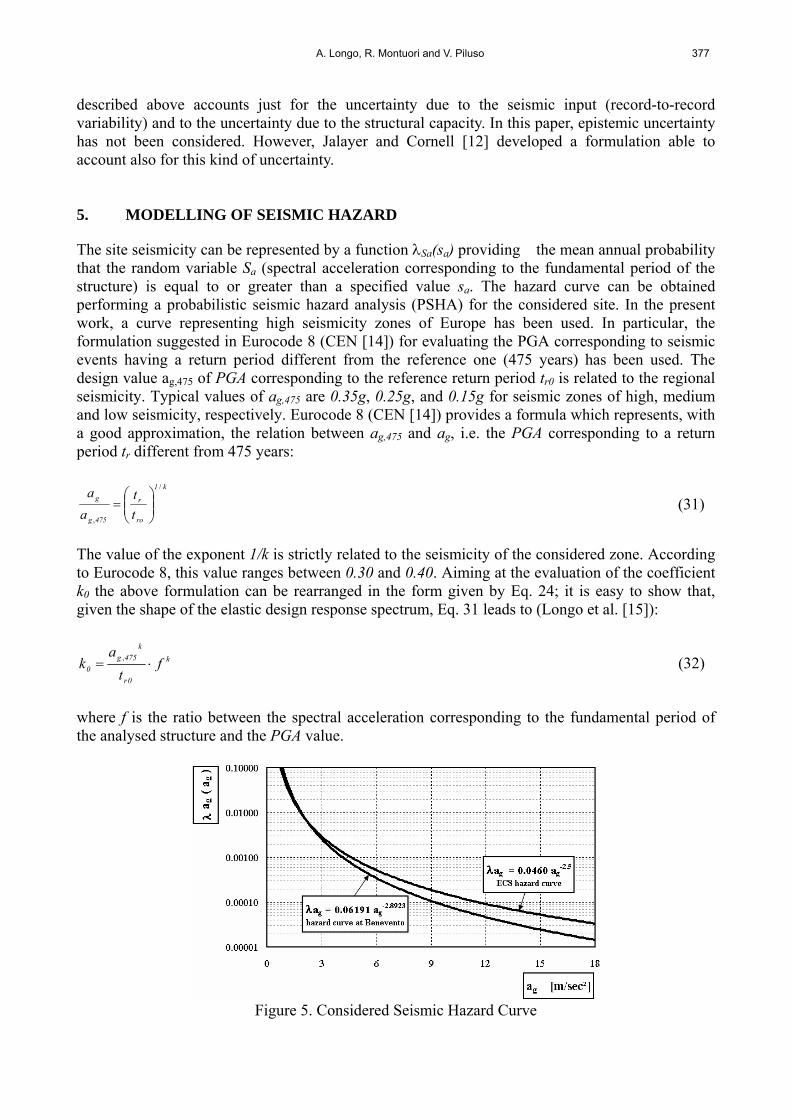
The site seismicity can be represented by a function Sa(sa) providing the mean annual probability that the random variable Sa (spectral acceleration corresponding to the fundamental period of the structure) is equal to or greater than a specified value sa. The hazard curve can be obtained performing a probabilistic seismic hazard analysis (PSHA) for the considered site. In the present work, a curve representing high seismicity zones of Europe has been used. In particular, the formulation suggested in Eurocode 8 (CEN [14]) for evaluating the PGA corresponding to seismic events having a return period different from the reference one (475 years) has been used. The design value ag,475 of PGA corresponding to the reference return period tr0 is related to the regional seismicity. Typical values of ag,475 are 0.35g, 0.25g, and 0.15g for seismic zones of high, medium and low seismicity, respectively. Eurocode 8 (CEN [14]) provides a formula which represents, with a good approximation, the relation between ag,475 and ag, i.e. the PGA corresponding to a return period tr different from 475 years:
k1
ro
r
475g
g
t
t
a
a/
,
(31)
The value of the exponent 1/k is strictly related to the seismicity of the considered zone. According to Eurocode 8, this value ranges between 0.30 and 0.40. Aiming at the evaluation of the coefficient k0 the above formulation can be rearranged in the form given by Eq. 24; it is easy to show that, given the shape of the elastic design response spectrum, Eq. 31 leads to (Longo et al. [15]):
k
0r
k
475g
0 ft
ak , (32)
where f is the ratio between the spectral acceleration corresponding to the fundamental period of the analysed structure and the PGA value.
Figure 5. Considered Seismic Hazard Curve

378 Seismic Reliability of Chevron Braced Frames with Innovative Conception of Bracing Members
The use of Eqs. 31 and 32, rather than the use of spectral acceleration hazard curves directly, has been preferred, because the aim of the paper is the comparison of the seismic performances of concentrically braced frames designed according to the two approaches summarized in Section 2, without reference to a specific site. However, it is useful to note that the coefficients k0 and k, corresponding to Eurocode 8 suggestions, are close to the ones provided for the Campania region (south Italy) by Creèmer et al. [16]. In Figure 5 the seismic hazard curves in terms of PGA are depicted.
6. PROBABILISTIC SEISMIC DEMAND ANALYSIS (PSDA) The study case herein investigated is constituted by the 4 storey structure depicted in Figure 6. Dead load and live load are, respectively, equal to 4kN/m2 and 2kN/m2. S235 steel grade has been adopted. The seismic design has been carried out with reference to high seismicity zone (ag=0.35g) considering a q-factor equal to 2.5. The chosen profiles for the “V”-braced frames are given in Table 1 and 2 both for the structure designed according to Eurocode 8 provisions (VBF-EC8) and for the structure designed according to the proposed methodology. With reference to the building designed by means of the proposed methodology, two cases have been analysed corresponding to bracing members with and without RSS (VBF-RSS and VBF-P respectively). In the same tables also the values of the overstrength coefficients i, the normalized slenderness and the geometry of the section reduction for RSS braces, are reported.
6.00
V-BRACED
6.00
6.00
6.00
6.00
6.00
V-B
RA
CE
D
V-B
RA
CE
D
V-BRACED6.006.00 6.00
4.00
4.00
4.00
4.00
2.00
2.00
2.00
2.00
2.00
2.00
2.00
2.00
2.00
Figure 6. The Analysed Structure
Table 1. Results for Eurocode 8 Design Criteria and for the Proposed Design Methodology VBF-EC8 [T0=0.58 sec] VBF-P [T0=0.60 sec]
Storey Bracing Columns Beams i i Bracing Columns Beams
i i
1 355.6×6.3 HE 340 B HEM 500 1.12 0.43 355.6×6.3 HE 320 B HEM 280 1.12 0.43 2 323.9×5.9 HE 240 B HEM 400 1.08 0.47 323.9×5.9 HE 260 B HEM 260 1.08 0.47 3 273×5.6 HE 180 B HEM 320 1.11 0.56 273×5.6 HE 200 B HEM 260 1.11 0.56 4 219.1×5 HE 100 A HEM 300 1.40 0.70 219.1×5 HE 120 B HEM 240 1.40 0.70
Table 2. Results for the Proposed Design Methodology including RSS
VBF-RSS [T0=0.61 sec] Storey Bracing Columns Beams i i i i
1 355.6×6.3 HE 320 B HEM 220 1.0 0.43 19.30° 0 2 323.9×5.9 HE 260 B HEM 240 1.0 0.47 12.63° 0 3 273×5.6 HE 180 B HEM 220 1.0 0.56 17.39° 0 4 219.1×5 HE 120 B HEM 220 1.0 0.70 46.74° 4.58°

A. Longo, R. Montuori and V. Piluso 379
Due to the different method used for the evaluation of the post buckling behaviour of compressed diagonal, a significant difference arises regarding the beam size. In particular, the net downward force acting on the beam provided by Eurocode 8 (Eq. 6) is significantly greater than the one obtained by the application of the proposed design methodology and, as a consequence, greater beam sections have to be chosen. It is important to underline that the fundamental period of vibration is very close to 0.60 sec for all VBFs, for this reason the coefficients k and k0 defining the site hazard curve have been evaluated considering the same structural period. In Figure 7 the values of k and k0 evaluated for T=0.60 sec are reported. The evaluation of demands and their uncertainties needs the availability of a set of ground acceleration time histories to represent the seismic hazard at different return periods and to describe intensity, frequency content and duration with sufficient comprehensiveness so that central values and measures of dispersion of demand parameters can be determined with confidence. A rigorous demand prediction needs inelastic time history analyses, so that records have to be selected for the aforementioned purpose. Table 3 reports the name and other information of selected records from PEER database (web site) [17]. In the same table the spectral ordinate corresponding the fundamental period of the examined structures (equal to 0.60 sec) are reported. The records are selected so that the mean spectrum shape is compatible with the design spectrum of Eurocode 8 for rigid soil (Figure 8).
Figure 7. Hazard Curve in Terms of Spectral Acceleration The application of the PSDA requires the selection of damage parameters (DM) able to describe the structural seismic response. In this work, the following damage parameters are considered: maximum interstorey drift ratio (MIDR); ratio between cyclic ductility demand f of diagonal member and its limit value fmax, computed
according to the formulation suggest by Tremblay [18]; ratio between the maximum column axial force and the corresponding out of plane buckling
resistance provided by Eurocode 3 (CEN [11]) formulation (Nmax/Nb.Rd, being Nmax the maximum
axial force obtained from dynamic non linear analysis and Nb.Rd the buckling resistance computed according to Eurocode 3).

380 Seismic Reliability of Chevron Braced Frames with Innovative Conception of Bracing Members
Table 3. Selected Records
N Record Date Component g
TSa )60.0( g
amax
length [sec]
1 Irpinia, Italy (Bagnoli) 23/11/1980 N-S 0.364 0.133 72.61 2 Cape Mendocino 25/04/1992 E-W 0.369 1.039 30.00 3 Elcentro 19/05/1940 E-W 0.516 0.226 29.78 4 Montenegro (Ercegov) 15/04/1979 E-W 0.307 0.230 25.00 5 Ferndale 1 19/09/1939 S-E 0.078 0.091 20.52 6 Ferndale 3 03/10/1941 N-E 0.146 0.112 17.05 7 Gazli USSR (Karakyr) 17/05/1976 N-S 1.037 0.608 16.25 8 Tokaki-Kenoki (Hachinoe) 17/05/1968 N-S 0.410 0.229 36.00 9 Helena Montana (Carrol College) 31/10/1935 E-W 0.175 0.153 9.67
10 Hollister (City Hall) 09/03/1949 S-W 0.251 0.117 17.03 11 Kern County (Taft Lincoln School) 21/07/1952 S-E 0.298 0.178 54.13 12 Kobe (Takarazuka) 16/01/1980 N-S 1.533 0.629 35.00 13 Livermore (Morgan Terr Park) 27/01/1980 N-W 0.326 0.252 30.00 14 Los Angeles 10/03/1933 N-E 0.156 0.065 25.78 15 Mammoth Lakes (Convict Creek) 25/05/1980 E-W 0.697 0.416 29.95 16 Ken-Oki (Miyagi) 1978 N-S 0.269 0.140 58.00 17 Northridge (Sylmar - Olive View) 17/01/1994 N-W 1.952 0.842 15.55 18 Olympia 13/04/1949 N-E 0.707 0.325 30.28 19 Parkfield (Templor) 28/06/1966 S-W 0.249 0.357 30.31 20 Montenegro (Petrovac) 15/04/1979 N-S 1.525 0.438 19.62 21 San Fernando (Hollywood Stor Lot) 09/02/1971 E-W 0.307 0.210 27.98 22 Friuli, Italy (San Rocco) 15/09/1976 N-S 0.138 0.035 16.92 23 Seattle 13/04/1949 N-W 0.128 0.076 20.10 24 Spitak, Armenia (Gukasian) 07/12/1988 N-S 0.340 0.199 19.90 25 Superstitn Hills (A)(Wildlife Liquef. Array) 24/11/1971 E-W 0.206 0.132 29.81 26 Taft 1 21/07/1952 N-W 0.281 0.157 30.00 27 Taft 3 21/07/1952 S-E 0.295 0.179 54.90 28 Friuli, Italy (Tarcento) 15/09/1976 N-S 0.119 0.139 20.10 29 Tokyo 1956 N-S 0.144 0.075 11.40 30 Vernon 10/03/1933 S-E 0.119 0.192 42.17
(a) (b)
Figure 8. Spectra of Considered Ground Motions
Figure 9. Ground Motions Spectra Scaled to the Same Spectral Acceleration at T=0.60
sec.
These parameters have been selected, because they correspond to three different structural failure modes: excess of storey damage; fracture of diagonal members; out-of-plane buckling of columns.

A. Longo, R. Montuori and V. Piluso 381
Aiming to determine the statistical distribution of demand parameters characterizing the seismic response of the considered structures, non-linear dynamic analyses have been carried out by means of the PC ANSR computer program (Maison [19]). The considered structural model accounts for column continuity, so that the columns are modelled by means of beam-column elements whose plastic domain accounts for moment-axial force interaction. The hysteretic behaviour is elastic-perfectly plastic without stiffness and strength degradation. In addition, the columns are assumed to be perfectly hinged at their base, while the beam-to-column connections transmit the shear forces only, so that the beams have been modelled as hinged at their ends. In other words, the structure is a pure CB-frame rather than a dual system. Therefore, the braces are the only lateral load resisting system. A preliminary prediction of the hysteretic behaviour of brace elements has been performed by means of Georgescu model (Georgescu et al. [7]). Successively, with reference to FE analysis, the modelling of the brace behavior has been performed by means of the Ikeda and Mahin model (Ikeda and Mahin [20]) whose parameters have been calibrated in order to provide the same energy dissipation as the more refined Georgescu model. In addition, for RSS bracing system the Georgescu model and the simplified Ikeda and Mahin model, are properly applied considering an equivalent slenderness and an equivalent stiffness. Regarding the modelling of columns, both in-plane and out-of plane buckling have been considered by performing, at each time step of numerical integration of motion equations, the stability checks according to Eurocode 3 (CEN [11]), considering the actual distribution of bending moments along the columns. The same check has been performed also for the beams. Incremental dynamic non linear analyses (IDA) (Vamvatsikos and Cornell [21] have been performed according to the multi stripe method (MSA) where each stripe represents a set of results obtained by scaling all the earthquake records to provide the same spectral acceleration value corresponding to the fundamental period of the structure (Figure 9). IDA analyses have been performed starting from a value of Sa equal to 0.05g and increasing the Sa value of 0.05g until the occurrence of dynamic instability. This phenomenon is due to the fact that, under load reversals, the previously buckled member could not return in its original alignment and the member which was previously in tension could exceed its capacity in compression. As a consequence, both diagonal members could be in a buckled condition. The dynamic instability phenomenon occurs when, at any storey, both diagonals are in a buckled configuration so that a soft-storey develops. The spectral acceleration corresponding to the attainment of dynamic instability can be defined as the value for which a very little increase of Sa causes an exponential increase of all damage parameters (DM) leading to numerical instability and lack of convergence in dynamic analysis. In the Figure 10, with reference to the designed structures, the results of IDA analyses are depicted in terms of the considered DM corresponding to storey 1. IDA curves show an horizontal asymptote when dynamic instability arises. As already noted, PSDA requires estimation of the statistical parameters of the distribution law of the structural demand (DM). The great variability of non linear dynamic analyses results, combined with the dynamic instability phenomenon (absence of numerical convergence), requires a more robust method than the moment method for evaluating the median DM|Sa and the dispersion DM|Sa. In the study case herein presented, the so called “three parameters model” has been adopted (Shome et al. [22]).

382 Seismic Reliability of Chevron Braced Frames with Innovative Conception of Bracing Members
Figure 10. IDA Curves Corresponding to First Storey for the Designed Structures
According to this method, fractiles can be calculated by means of the following relationships:
)(exp')( ' psasdm 1NCDMNCDM
b
aap if 0aa ss (33)
CaaNCDMNCDM
baap sspsasdm 0
1' exp')( if 0aa ss (34)
where a’ and b’ can be obtained by means of a power regression of median values of the considered demand parameter, calculated with the ordered statistic method with reference to the subset of data corresponding to records for which dynamic instability does not occur. Therefore, DM|NC=a’·sa
b’
is the median value of DM conditioned to Sa and conditioned to the above sub-set, DM|NC is the corresponding dispersion and is the standard normal probability function. The coefficients sa0 and C are evaluated by modelling the non collapse probability (function of spectral acceleration) by means of following expressions:
1sp aSNC a)(| if 0aa ss (35)
C
a
aaSNC s
ssp
a
0,| )( if 0aa ss (36)
A. Longo, R. Montuori and V. Piluso 383
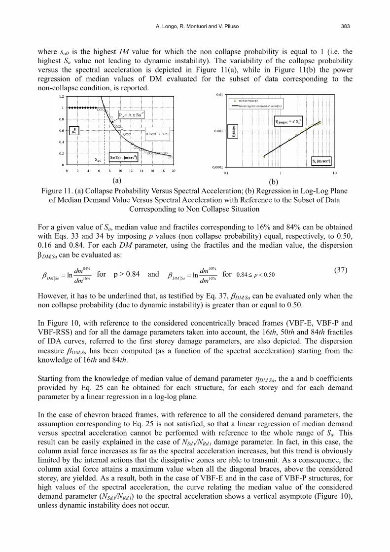
where sa0 is the highest IM value for which the non collapse probability is equal to 1 (i.e. the highest Sa value not leading to dynamic instability). The variability of the collapse probability versus the spectral acceleration is depicted in Figure 11(a), while in Figure 11(b) the power regression of median values of DM evaluated for the subset of data corresponding to the non-collapse condition, is reported.
(a)
(b)
Figure 11. (a) Collapse Probability Versus Spectral Acceleration; (b) Regression in Log-Log Plane of Median Demand Value Versus Spectral Acceleration with Reference to the Subset of Data
Corresponding to Non Collapse Situation For a given value of Sa, median value and fractiles corresponding to 16% and 84% can be obtained with Eqs. 33 and 34 by imposing p values (non collapse probability) equal, respectively, to 0.50, 0.16 and 0.84. For each DM parameter, using the fractiles and the median value, the dispersion DM|Sa can be evaluated as:
%16
%84
lndm
dmSaDM for p > 0.84 and
%16
%50
lndm
dmSaDM for 50.084.0 p (37)
However, it has to be underlined that, as testified by Eq. 37, DM|Sa can be evaluated only when the non collapse probability (due to dynamic instability) is greater than or equal to 0.50. In Figure 10, with reference to the considered concentrically braced frames (VBF-E, VBF-P and VBF-RSS) and for all the damage parameters taken into account, the 16th, 50th and 84th fractiles of IDA curves, referred to the first storey damage parameters, are also depicted. The dispersion measure DM|Sa has been computed (as a function of the spectral acceleration) starting from the knowledge of 16th and 84th. Starting from the knowledge of median value of demand parameter DM|Sa, the a and b coefficients provided by Eq. 25 can be obtained for each structure, for each storey and for each demand parameter by a linear regression in a log-log plane. In the case of chevron braced frames, with reference to all the considered demand parameters, the assumption corresponding to Eq. 25 is not satisfied, so that a linear regression of median demand versus spectral acceleration cannot be performed with reference to the whole range of Sa. This result can be easily explained in the case of NSd.i/NRd.i damage parameter. In fact, in this case, the column axial force increases as far as the spectral acceleration increases, but this trend is obviously limited by the internal actions that the dissipative zones are able to transmit. As a consequence, the column axial force attains a maximum value when all the diagonal braces, above the considered storey, are yielded. As a result, both in the case of VBF-E and in the case of VBF-P structures, for high values of the spectral acceleration, the curve relating the median value of the considered demand parameter (NSd.i/NRd.i) to the spectral acceleration shows a vertical asymptote (Figure 10), unless dynamic instability does not occur.

384 Seismic Reliability of Chevron Braced Frames with Innovative Conception of Bracing Members
The log-log representation of the median demand versus spectral acceleration curve shows two ranges where a linear regression, leading to a relationship in the form of Eq. 37, can be applied. The Sa value separating the two ranges has been evaluated by means of a procedure aiming at the maximization of the correlation coefficient for each regression curve. The above representation is provided in Figure 12 where reference is made, as an example, to the demand parameter NSd/NRd evaluated for the first storey.
Figure 12. Regression in Log-Log Plane of Demand Median Value Versus Spectral Acceleration: NSd.1/NRd.1 Damage Parameter (Storey 1 and VBF-EC8 Structure)
Table 4 summarizes the statistical parameters of demand distribution for each considered damage parameter, for each storey and for each structure. In the aforementioned table the notation MIDRi represents the maximum interstorey drift ratio for ith storey, (f/fmax)i represents the ratio between cyclic ductility demand f of diagonal member and its limit value fmax for ith storey and (NSd/NRd)i is ratio between the maximum column axial force and the corresponding out of plane buckling resistance provided by Eurocode 3 for ith storey. In particular the values of a and b and the range of Sa for the applicability of Eq. 25, which have been evaluated by means of a power regression of the median values obtained with the three parameters model described above, are reported. In the same table, also the mean values of DM|Sa evaluated in the range of application of Eq. 25 are pointed out. In addition, the notation N.D. points out cases for which the median value of the demand parameter DM|Sa cannot be defined, because the number of earthquake records leading to dynamic instability exceeds 50%. However, it has to be underlined that the above occurs for high Sa values so that other failure modes are already relevant as testified by the LS (mean annual probability of exceeding a limit state) values presented in Section 8. 7. PROBABILISTIC SEISMIC CAPACITY ANALYSIS (PSCA) The structural capacity defines the limit (threshold) value for the demand (state) variable to identify acceptable structural behaviours. In this work, three demand variables have been considered; therefore, three limits of capacity have been defined, corresponding, to three different structural failure modes: excess of storey damage, fracture of diagonal members and out-of-plane buckling of columns.

A. Longo, R. Montuori and V. Piluso 385
Table 4. PSDA Results for the Three Designed Structures VBF-EC8 VBF-P VBF-RSS
DM Sa /g a b DM|Sa Sa /g a b DM|Sa Sa /g a b DM|Sa
≤0.70 4·10-4 0.9240 0.2728 ≤0.90 4·10-4 0.9796 0.4237 ≤0.70 5·10-4 0.9353 0.32190.70÷2.05 7·10-6 3.0002 0.8997 0.90÷1.60 7·10-6 2.8675 1.5396 0.70÷0.85 9·10-11 9.3014 1.0786MIDR1 2.05÷2.95 3·10-9 5.6107 1.4850 N.D. N.D. N.D. N.D. N.D. N.D. N.D. N.D. ≤1.00 6·10-4 0.8962 0.3892 ≤1.10 6·10-4 0.9204 0.5270 ≤0.70 6·10-4 0.9164 0.2945
1.00÷1.8 2·10-5 2.4376 1.0087 1.10÷1.45 3·10-9 5.9048 1.3173 0.70÷0.90 7·10-5 2.0714 0.4578MIDR2 1.80÷2.95 3·10-9 5.6107 1.7705 N.D. N.D. N.D. N.D. N.D. N.D. N.D. N.D. ≤1.00 6·10-4 11.778 0.3984 ≤1.45 6·10-4 1.3374 0.6819 ≤0.65 8·10-4 1.1017 0.4371
1.00÷1.80 1.6·10-3 0.7173 0.4812 N.D. N.D. N.D. N.D. 0.65÷0.80 1·10-7 5.7252 1.2468MIDR3 1.80÷3.15 5·10-4 1.1293 0.3369 N.D. N.D. N.D. N.D. N.D. N.D. N.D. N.D. ≤1.00 8·10-4 1.0297 0.2982 ≤1.45 7·10-4 1.2212 0.3607 ≤0.65 0.001 1.0225 0.4253
1.00÷1.80 2·10-3 0.6015 0.2676 N.D. N.D. N.D. N.D. 0.65÷0.85 2·10-5 3.2325 0.7962MIDR4 1.80÷3.20 6·10-4 1.0024 0.3379 N.D. N.D. N.D. N.D. N.D. N.D. N.D. N.D. ≤0.80 6.5·10-2 0.8648 0.200 ≤0.85 0.066 0.8697 0.2802 ≤0.75 0.0745 0.9666 0.1981
0.80÷2.25 1·10-3 2.8672 0.7997 0.85÷1.45 9·10-4 2.8896 1.5266 0.75÷1.10 7·10-7 6.7209 1.8433(f/fmax)1 2.25÷2.60 2·10-9 7.147 1.1649 N.D. N.D. N.D. N.D. N.D. N.D. N.D. N.D. ≤0.80 6.7·10-2 0.7953 0.3162 ≤1.10 0.0619 0.8394 0.4791 ≤0.75 0.0256 1.5077 0.1668
0.80÷2.25 5·10-4 2.9151 1.039 1.10÷1.45 5·10-9 7.6712 1.6981 0.75÷1.10 0.0702 0.9626 0.4283(f/fmax)2 2.25÷2.75 1·10-7 5.7118 1.4640 N.D. N.D. N.D. N.D. N.D. N.D. N.D. N.D. ≤0.45 5.7·10-2 0.9733 0.1815 ≤0.85 0.0527 1.2317 0.4638 ≤0.70 0.0637 1.0856 0.4481
0.45÷0.60 1.3·10-3 3.5136 0.560 0.85÷1.45 2·10-4 3.7724 1.5684 0.70÷0.85 2·10-7 7.6772 1.5627(f/fmax)3 0.60÷2.75 2·10-1 0.6659 0.4556 N.D. N.D. N.D. N.D. N.D. N.D. N.D. N.D. ≤0.45 4.4·10-2 1.019 0.2713 ≤1.5 0.0381 1.3612 0.5025 ≤0.45 0.0650 1.0674 0.4160
0.45÷0.60 2·10-3 3.136 0.6588 N.D. N.D. N.D. N.D. 0.45÷0.90 5·10-4 3.6051 0.8397(f/fmax)4 0.60÷2.75 0.110 0.8323 0.3425 N.D. N.D. N.D. N.D. N.D. N.D. N.D. N.D. ≤0.45 0.288 0.6588 0.0088 ≤0.45 0.3057 0.6604 0.0906 ≤0.45 0.3087 0.6592 0.0655
(NSd/NRd)1 0.45÷2.75 0.7551 0.0814 0.0689 0.45÷1.55 0.7181 0.0934 0.0505 0.45÷0.85 0.6337 0.1686 0.0892≤0.45 0.3371 0.6064 0.0997 ≤0.45 0.2931 0.6052 0.1010 ≤0.45 0.2970 0.6106 0.0663
(NSd/NRd)2 0.45÷2.75 0.7001 0.0927 0.0371 0.45÷1.55 0.6122 0.1023 0.0403 0.45÷0.85 0.6276 0.0815 0.0507≤0.45 0.3610 0.5184 0.1225 ≤0.45 0.2761 0.5236 0.1224 ≤0.45 0.3542 0.5125 0.0892
(NSd/NRd)3 0.45÷2.75 0.5631 0.2174 0.0784 0.45÷1.55 0.4715 0.1465 0.0345 0.45÷0.85 0.7214 0.0314 0.0182≤0.40 0.5270 0.0304 0.1033 ≤0.45 0.2535 9.8·10-3 0.0856 ≤0.45 0.2558 5·10-5 0.0840
0.40÷0.65 0.0278 2.3509 0.6315 0.45÷0.60 0.0115 2.2904 0.4993 0.45÷0.60 0.0039 2.8381 0.5631(NSd/NRd)4 0.65÷3.15 0.7011 0.5267 0.1552 0.60÷1.45 0.2190 0.5529 0.2777 0.60÷0.85 0.3295 0.2936 0.5240
The limit value of MIDR is not simple to establish. Different suggestions can be found in FEMA 273 [23] and FEMA 350 [24]. In the following, reference is made for the collapse prevention limit state to a median value of capacity C equal to 2% while the dispersion value C has been assumed equal to 0.20 (FEMA 350 [24]). Regarding the limit value of the cyclic ductility of bracing members, the following expression suggested by Tremblay [18] on the basis of experimental results has been considered:
3842μ f ..max, (38)
As shown by Eq. 38, the cyclic ductility limit is a function of the normalized slenderness and this limit increases as far as the normalized slenderness increases, i.e., the limit is more restrictive for stocky braces rather than for intermediate or slender braces. However, by considering as damage parameter the ratio between the brace ductility demand and the corresponding ductility supply, the normalized limit value is equal to 1.0 and, therefore, independent of the considered storey. The dispersion capacity associated with the f/f.max damage parameter can be derived from the available experimental data. In particular, according to the experimental data collected by Tremblay [18], the ratio between the experimental value of the cyclic ductility supply exp and the theoretical value provided by Eq. 38 has a mean value equal to 1.0, with a coefficient of variation equal to 0.25.

386 Seismic Reliability of Chevron Braced Frames with Innovative Conception of Bracing Members
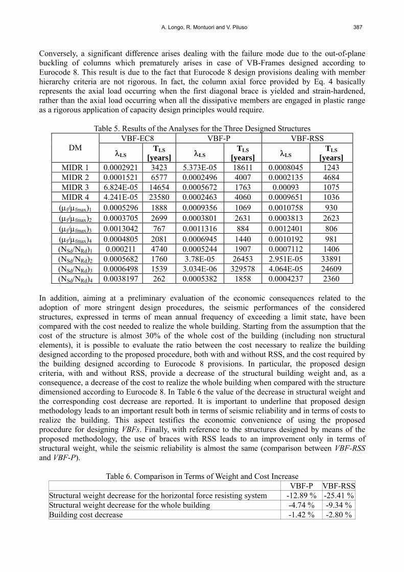
The third considered damage parameter is related to the column axial load and it is equal to NSd/NRd, where, NSd is the maximum axial load obtained by the non linear analysis and NRd, is the theoretical limit value corresponding to the out-of-plane buckling computed according to Eurocode 3 [11]). The theoretical limit value of the above ratio is equal to 1.0. Regarding the dispersion, a coefficient of variation equal to 0.10 has been assumed according to the general suggestions given in EN 1990 (CEN [25]). 8. MEAN ANNUAL FREQUENCY OF EXCEEDING A LIMIT STATE The application of Jalayer and Cornell [12] approach allows to determine the mean annual frequency of exceeding a limit state. With reference to the examined structures, for each storey and for each considered damage parameters, the results obtained, by means of the application of Eq. 29, using the statistical parameters reported in Table 4 (a, b and DM|Sa), are given in Table 5. In particular, the parameters a, b and DM|Sa are chosen in the range of Sa wherein the median value of the considered damage parameter DM is equal to the corresponding capacity value. In the case of NSd/NRd damage parameter, Eq. 27 cannot be applied, because the range of interest of Sa the b value is very close to zero. Therefore, in order to overcome this drawback, the evaluation of the mean annual frequency of exceeding the considered limit state, for this damage parameter, has been carried out by means of the numerical integration of Eq. 23. Eurocode 8 [4] provisions (VBF-EC8) lead to a satisfactory behaviour in terms of MIDR and cyclic ductility of diagonal members. In fact, the mean annual frequency of exceeding such limit states, LS, is low and the corresponding return period TR,LS (equal LS
-1) is clearly greater than the return period assumed for defining the design seismic action (T475=475 years). Conversely, regarding the damage parameter corresponding to column buckling, Eurocode 8 provisions exhibit the worst behaviour. In fact, the probability of failure of VBF-EC8 is significant and the return period corresponding to the considered limit state is lower than 475 years. On the other hand, the structures designed by means of the procedure proposed by the authors (Longo et al. [1]; Longo et al. [2, 3, 26]) with and without RSS (VBF-RSS and VBF-P) exhibit a good performance with reference to all the considered damage parameters. Comparing the maximum probability of failure occurring with reference to the designed structures (maximum value between all the damage parameters and for all the storeys), it can be recognized that in the case of the structure designed according to Eurocode 8 provisions (VBF-EC8) it is almost 3.5 times greater than that corresponding to the same structure designed according to the proposed methodology with traditional conception of bracing members (VBF-P). In fact, in this case the return period associated with the attainment of the collapse condition for VBF-EC8 is equal to 262 years while for the VBF-P this value is equal to 884. The seismic improvement observed with reference to VBF-P is also confirmed in the case of the structure designed according to the proposed procedure with RSS bracing members because the return period of VBF-EC8 is almost 3.0 times less than the one computed for VBF-RSS structure (263 years versus 806). The above results show that the seismic performance in terms of storey damage (MIDR) and ductility demand of dissipative members (f/f.max) of VB-Frames designed according to Eurocode 8 is comparable to that obtained in the case of VB-Frames designed according to the proposed methodology.
A. Longo, R. Montuori and V. Piluso 387
Conversely, a significant difference arises dealing with the failure mode due to the out-of-plane buckling of columns which prematurely arises in case of VB-Frames designed according to Eurocode 8. This result is due to the fact that Eurocode 8 design provisions dealing with member hierarchy criteria are not rigorous. In fact, the column axial force provided by Eq. 4 basically represents the axial load occurring when the first diagonal brace is yielded and strain-hardened, rather than the axial load occurring when all the dissipative members are engaged in plastic range as a rigorous application of capacity design principles would require.
Table 5. Results of the Analyses for the Three Designed Structures VBF-EC8 VBF-P VBF-RSS
DM LS
TLS
[years] LS TLS
[years] LS TLS
[years] MIDR 1 0.0002921 3423 5.373E-05 18611 0.0008045 1243 MIDR 2 0.0001521 6577 0.0002496 4007 0.0002135 4684 MIDR 3 6.824E-05 14654 0.0005672 1763 0.00093 1075 MIDR 4 4.241E-05 23580 0.0002463 4060 0.0009651 1036
(f/fmax)1 0.0005296 1888 0.0009356 1069 0.0010758 930 (f/fmax)2 0.0003705 2699 0.0003801 2631 0.0003813 2623 (f/fmax)3 0.0013042 767 0.0011316 884 0.0012401 806 (f/fmax)4 0.0004805 2081 0.0006945 1440 0.0010192 981 (NSd/NRd)1 0.000211 4740 0.0005244 1907 0.0007112 1406 (NSd/NRd)2 0.0005682 1760 3.78E-05 26453 2.951E-05 33891 (NSd/NRd)3 0.0006498 1539 3.034E-06 329578 4.064E-05 24609 (NSd/NRd)4 0.0038197 262 0.0005382 1858 0.0004237 2360
In addition, aiming at a preliminary evaluation of the economic consequences related to the adoption of more stringent design procedures, the seismic performances of the considered structures, expressed in terms of mean annual frequency of exceeding a limit state, have been compared with the cost needed to realize the whole building. Starting from the assumption that the cost of the structure is almost 30% of the whole cost of the building (including non structural elements), it is possible to evaluate the ratio between the cost necessary to realize the building designed according to the proposed procedure, both with and without RSS, and the cost required by the building designed according to Eurocode 8 provisions. In particular, the proposed design criteria, with and without RSS, provide a decrease of the structural building weight and, as a consequence, a decrease of the cost to realize the whole building when compared with the structure dimensioned according to Eurocode 8. In Table 6 the value of the decrease in structural weight and the corresponding cost decrease are reported. It is important to underline that proposed design methodology leads to an important result both in terms of seismic reliability and in terms of costs to realize the building. This aspect testifies the economic convenience of using the proposed procedure for designing VBFs. Finally, with reference to the structures designed by means of the proposed methodology, the use of braces with RSS leads to an improvement only in terms of structural weight, while the seismic reliability is almost the same (comparison between VBF-RSS and VBF-P).
Table 6. Comparison in Terms of Weight and Cost Increase VBF-P VBF-RSS
Structural weight decrease for the horizontal force resisting system -12.89 % -25.41 %Structural weight decrease for the whole building -4.74 % -9.34 %Building cost decrease -1.42 % -2.80 %

388 Seismic Reliability of Chevron Braced Frames with Innovative Conception of Bracing Members
9. CONCLUSIONS In this paper the procedure proposed by Jalayer and Cornell [12] for the evaluation of seismic reliability of structures has been applied for “V” braced frames designed according to two different methodologies. In addition, the influence of the weakening of the brace at its ends has been evaluated. The obtained results have pointed out a good seismic behaviour of the structures designed according to the proposed methodology (VBF-P without RSS and VBF-RSS with RSS) for all the considered damage parameters. In particular, by comparing these results with those obtained for the structure designed according to Eurocode 8 provisions (CEN [4]), a big difference arises due to the premature out of plane buckling of columns. Conversely, the return period associated with this limit state (i.e. column buckling), with reference to the structures designed according to the proposed methodology (VBF-P and VBF-RSS), is very large when compared with the return period associated to the ultimate limit state (475 years). In addition, it has to be stressed that the proposed methodology leads to lighter structures and, as a consequence, to a reduction of the whole building cost. This result is more evident in the case of the structure designed according to the proposed procedure and with RSS bracing members. In fact, the structural weight of the whole building is about 9% less than the weight of the building with concentrically braced frames designed according to Eurocode 8 provisions. A possible development of the work could be the consideration of random material variability too. REFERENCES [1] Longo, A., Montuori, R., Piluso, V., “Plastic Design of Seismic Resistant V-Braced
Frames,” 4rd European Conference on Steel Structures, Maastricht, 2005a. [2] Longo, A., Montuori, R., Piluso, V., “Failure Mode Control of X-Braced Frames under
Seismic Actions”, Journal of Earthquake Engineering, 2008a, Vol. 12, pp. 728-759. [3] Longo, A., Montuori, R. and Piluso, V. “Influence of Design Criteria on Seismic Reliability
of X-Braced Frames”, Journal of Earthquake Engineering, 2008b, Vol. 12, pp. 406-431. [4] CEN, prEN 1998–Eurocode 8: Design of Structures for Earthquake Resistance. Part 1:
General Rules, Seismic Actions and Rules for Buildings, 2003a. [5] Longo, A., Montuori, R., Piluso, V., “An Innovative Conception For Bracing Members:
The Reduced Brace Section Solution”, 4rd European Conference on Steel Structures, Maastricht, 2005b.
[6] Giugliano, M.T., Longo, A., Montuori, R. and Piluso, V., “Controventi Innovativi del tipo RSS: Regole di Progetto ed Affidabilità Sismica”, Ingegneria Sismica, 2007, Vol. 3, ISSN: 0393-1420, pp. 7 — 24.
[7] Georgescu, D., Toma, C. and Gosa, O., “Post-Critical Behaviour of ‘K’ Braced Frames”, Journal Construct Steel Research, 1992, Vol. 21, pp 115-133.
[8] UNI EN 10002/1: Steel material, Tensile Test, 1992. [9] Skuber, P., Beg, D. and Sinur, F. “Experimental Analysis of DC90 Energy Absorber
Device” PROHITECH - WP7 Internal Report, 2006. http://www.fgg.uni-lj.si/kmk/PROHITECH/wp7_files/WP7-DC90.pdf
[10] Skuber, P. and Beg, D., “DC90 Energy Absorber Device”– PROHITECH - WP8 Internal Report, http://www.fgg.uni-lj.si/kmk/PROHITECH/WP8-DC90.pdf, 2008.
[11] CEN, prENV 1993-1-1 – Eurocode 3: Design of Steel Structures. Part 1: General Rules and Rules for Buildings, Comité Européen de Normalisation, July 2003b.
[12] Jalayer, F. and Cornell, C.A., “A Technical Framework for Probability-Based Demand and Capacity Factor Design (DCFD)”, Seismic Formats, PEER Report 2003/06, 2003.

A. Longo, R. Montuori and V. Piluso 389
[13] Giovenale, P., “Valutazione del Rischio Sismico di Strutture:Ccaratterizzazione dell’azione e tecniche di analisi”, PhD Thesis, Supervisor: Ciampoli, M., University of Roma, 2002.
[14] CEN, prEN 1998-2. Eurocode 8: Design of Structures for Earthquake Resistance. Part 2: Bridges, 2003c.
[15] Longo, A., Montuori, R. and Piluso, V., “Seismic Reliability of V-Braced Frames: Influence of Different Design Approaches”, Stessa 2006, 5th International Conference on Behavior of Steel Structures in Seismic Areas, Yokohama, Japan, 14-17 August. Rotterdam:Balkema, 2006.
[16] Creèmer, C., Anamaterous, G., Monti, G. and Pinto, P.E., “Seismic Risk Assessment on an R.C. Bridge – Effect of Asynchronous Input Motions” – Saferr Mid –Term Review – ISPA, 2002.
[17] Pacific Earthquake Engineering Research Center, PEER Strong Motion Database, http://peer.berkeley.edu/smcat.
[18] Tremblay, R., “Inelastic Seismic Response of Steel Bracing Members”, Journal of Constructional Steel Research, Elsevier, 2002, Vol. 58, pp. 665-701.
[19] Maison, B.F., "PC-ANSR, A Computer Program for Nonlinear Structural Analysis", University of California (Berkeley) - http://nisee.berkeley.edu/software/pcansr, 1992.
[20] Ikeda, K. and Mahin, S.A., “A Refined Physical Theory Model for Predicting the Seismic Behaviour of Braced Frames”, Report UMEE 77R3, Department of Civil Engineering, The University of Michigan, 1984.
[21] Vamvatsikos, D. and Cornell, C.A., “Incremental Dynamic Analysis”, Earthquake Engineering and Structural Dynamics, 2002, Vol. 31, No. 3, pp. 491-514.
[22] Shome, N., Cornell, C.A. and Asce, M., “Structural Seismic Demand Analysis: Consideration of Collapse” 8th ASCE Specially Conference on Probabilistic Mechanics and Structural Reliability, 2000.
[23] FEMA 273, “Guidelines for the Seismic Rehabilitation of buildings”, Washington, DC: Federal Emergency Management Agency, 1997.
[24] FEMA 350, “Recommended Seismic Design Criteria for Steel Moment-Frames Buildings”, Washington, DC: Federal Emergency Management Agency, 2000.
[25] CEN, EN 1990–Eurocode – Basis of Structural Design, Comité Européen de Normalisation, 2001.
[26] Longo, A, Montuori, R. and Piluso, V., “Plastic Design of Seismic Resistant V-Braced Frames”, Journal of Earthquake Engineering, 2008c, 12:8,1246 — 1266.