seismic evaluation and strengthening of vertical and horizontal pressurevessels in a refining
TRANSCRIPT

The 14th
World Conference on Earthquake Engineering October 12-17, 2008, Beijing, China
Seismic Evaluation and Strengthening of Vertical and Horizontal PressureVessels in a Refining Complex
Hossein.kazem 1 and Mahmood.Minavand 2
1 Assistant Prof. Dept. of Structural Engineering. Islamic Azad University. South Tehran branch. Tehran/Iran 2 MS Student, Dept. of Structural Engineering. Islamic Azad University. Science and Research branch.
Tehran/Iran. Email: [email protected], [email protected]
ABSTRACT: Pressure vessels are one of the most important equipments in the refining of the crude oil. For this reason, these equipments must be resisting against the loads resulting from the earthquake. Pressure vessels are found in different units of refineries and in different vertical and horizontal shapes. These equipments are locating on different foundation and their seismic behaviors are quite different. For seismic study of pressure vessels, at first these equipments must be screened and categorized in order to find their real behavior. The selected sample should be a sample that in comparing to others must have critical condition in terms of seismic vulnerabilities. According to the qualitative studying, mechanical specifications such as dimensions, temperature, weight, and the dimensions of the foundation will be determined. After analytical modeling and calculations the amount of vessel vulnerabilities will be found. All the modeling is analyzed with the SAP2000 and SAFE2000 software. For modal and spectrum dynamic analysis shell elements and frame elements is used. After analysis is done, the stresses and the displacements in the body of vessel and also stresses in the pedestal and bolts will be determined and then compared to the allowable values. At the end those elements which have no adequate strength, will be retrofitted and all drawings and details will be presented. KEYWORDS: Acceptance Criteria, Equipment, Pressure vessels, Retrofit, Seismic. 1. INTRODUCTION:
In spite of abundant scientific developments in the field of the production of non-petroleum fuels on the world, oil and its products are still the most important source of the energy of industry in the world especially in the industrially developed countries. In the meantime, the oil countries earn billions of dollars yearly from selling of oil. On the other hand, with regard to the case that most of the oil countries are earthquake-prone, the safety of oil equipments against the earthquake is very important. The discussion of this paper will be the evaluation and seismic improving of pressure vessels which are among the most important of equipments in the field of refining oil.
2. VESSELS DESCRIPTION In quantities studies of seismic evaluation of refinery equipments, the refinery equipments such as pressure vessels for seismic reasons are selected according to the standing position of the equipment in the form of vertical or horizontal, supporting structure, the situation of bases and supports of the equipment and so on. Then equipment is qualitatively studied as the representative of its similar equipments. The selected equipment should have the most critical seismic situation among its similar equipments. In this paper one horizontal and one vertical pressure vessel which are shown in Figure 2.1 are studied as the representatives of their similar pressure vessels.

The 14th
World Conference on Earthquake Engineering October 12-17, 2008, Beijing, China
(a)-A typical of vertical pressure vessel (b) - A typical of horizontal pressure vessel Figure 2.1The selected pressure vessels
3. LOADING The load considered on the structure consists of the dead load, live load, thermal load, internal pressure load and earthquake load. In calculating the seismic loads, according to the ASCE, the specialized spectrum for structure with %5 damping is used. The base shear produced from seismic loads is calculated according to the Iranian code 2800 that is shown in the Eqn. 3.1.
In which Sa is the spectrum acceleration, R which is related to the ductility, I is the importance factor of the pressure vessel, and W is the seismic weight of the pressure vessel that is considered equivalent to the production weight according to the ASCE. (The operation weight of the horizontal pressure vessel is equal to 63 tons and the operation weight of the vertical pressure vessel is equal to 867 tons). With regard to the case that pressure vessels are categorized as part of the essential and important structures, their importance coefficient is considered equivalent to 1. The R factor for pressure vessels is considered 3 for both of the pressure vessels with regard to their structural specifications and also with the aid of the tables in the ASCE. According to the site observation and geotechnical studying, the type of soil according to the Iranian code 2800 is selected to be type III. The values of the spectrum acceleration are obtained according to the periods and geometry of the pressure vessels. The period of the studied pressure vessels are calculated based on the
following Equation. )3.2(
In which H is the height of the pressure vessel, D is the diameter of the pressure vessel, and t is the thickness of the shell of the pressure vessel. Regarding to the period of the pressure vessels the quantity of spectrum acceleration for horizontal vessel S a =0.7 and for vertical vessel S a =0.65 are obtained. The values of damping for both pressure vessels are supposed to be %5 damping.
The 14th
World Conference on Earthquake Engineering October 12-17, 2008, Beijing, China
The gravity and lateral loading combinations in this paper are according to the ASCE. For considering earthquake load in each direction, 100% of X or Y earthquake load direction with 30% of it s perpendicular direction is considered.
4. ANALYSIS In this stage the pressure vessels are modeled with the aid of software SAP2000 and the static and lateral loads are used. The static and dynamic (spectrum) method are used for analysis the pressure vessels. According to the ASCE, the base shear from dynamic analysis should be scaled at least 80 percent of the static base shear from static analysis 5. ACCEPTANCE CRITERIA The next step is to calculate the stresses, displacements and rotations of critical points and compare the results with the allowable values regarding to the vulnerability of the vessels. According to the ASCE, if the spectrum analysis is used therefore the demand load combination and capacity is chosen as table 5.1.
Table 5.1 the quantities of capacity and demand Capacity Demand
Allowed stress for operating condition ×1.6 and or the ultimate stress of the
member regarding to the multiplied loads DL+LL+T+P+(E/Q)
Q represents the reduction coefficient based on the ductility. The quantity of this coefficient is according to the table which is in the ASCE manual in this case this quantity is 3.5 for horizontal pressure vessel and 4 for vertical pressure vessel.
6. STRESS CONTROL IN THE SHELL In this part the maximum stress on the shell of the horizontal and vertical pressure vessels are determined only under the most critical load combination.
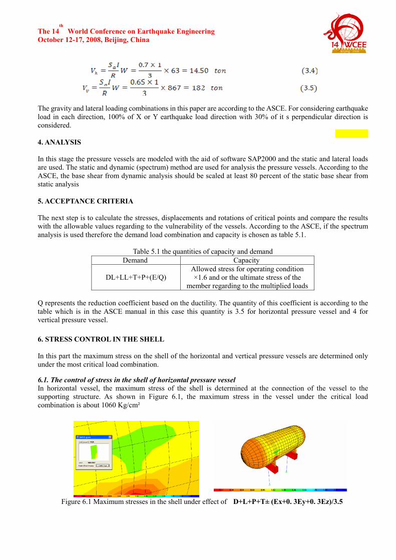
6.1. The control of stress in the shell of horizontal pressure vessel In horizontal vessel, the maximum stress of the shell is determined at the connection of the vessel to the supporting structure. As shown in Figure 6.1, the maximum stress in the vessel under the critical load combination is about 1060 Kg/cm²
Figure 6.1 Maximum stresses in the shell under effect of D+L+P+T± (Ex+0. 3Ey+0. 3Ez)/3.5

The 14th
World Conference on Earthquake Engineering October 12-17, 2008, Beijing, China
6.2. The control of stress in the shell of vertical pressure vessel: The maximum stress is determined at the foot of vertical pressure vessel and at the connection place to the supports. As it is seen in the Figure 6.2, the maximum stress in the pressure vessel under the effect of the critical load combination is about 1217 Kg/cm²
Figure 6.2 Maximum stresses in the shell under the effect of D+L+P+T± (Ex+0. 3Ey+0. 3Ez)/4 As it is seen the maximum stress on the shell of the pressure vessels is less than the allowable stress(1.6× 0.66Fy=2534 Kg/cm²). Therefore the body of the pressure vessels is safe against the critical seismic load combination.
7. THE CONTROL OF THE VESSELS BODY AT THE PEDESTAL CONNECTION 7.1. The control of the connection of horizontal pressure vessel to the pedestal The horizontal pressure vessel is connected to pedestal by 4 bolts 3.2cm diameter. The details of the connection to the base are shown in Figure 7.1. At first, the shear capacity of the connection is controlled according to the Eqn. 7.1.
Figure 7.1The detail of the pressure vessel connection to the pile and its reinforcement
(7.1)
In which D is the diameter of the bolts, uf is the ultimate stress of the bolts, DV is the maximum shear under the
load combination and CV is the concrete shear resistant of the bolts. Also, it is essential to control the bending capacity of the connection through the Eqn.7.2. The pressure vessel is connected to the concrete pile by four
The 14th
World Conference on Earthquake Engineering October 12-17, 2008, Beijing, China
bolts that are located 2.75 meters from each other.
(7.2)
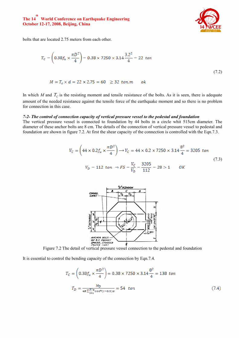
In which M and CT is the resisting moment and tensile resistance of the bolts. As it is seen, there is adequate amount of the needed resistance against the tensile force of the earthquake moment and so there is no problem for connection in this case. 7-2- The control of connection capacity of vertical pressure vessel to the pedestal and foundation The vertical pressure vessel is connected to foundation by 44 bolts in a circle whit 515cm diameter. The diameter of these anchor bolts are 8 cm. The details of the connection of vertical pressure vessel to pedestal and foundation are shown in figure 7.2. At first the shear capacity of the connection is controlled with the Eqn.7.3.
(7.3)
Figure 7.2 The detail of vertical pressure vessel connection to the pedestal and foundation
It is essential to control the bending capacity of the connection by Eqn.7.4.

The 14th
World Conference on Earthquake Engineering October 12-17, 2008, Beijing, China
In which DM is the maximum moment obtained from load combinations, N is the number of bolts and α is central angle between the bolts. According to the result obtained, the connection capacity of both horizontal and vertical pressure vessels to the supporting structure is appropriate and safe.
8. THE CONTROL OF THE OF FOUNDATION: The dimensions of foundation are controlled for settlement and stress in the soil. In this case the foundation without the reinforcement is modeled by SAFE2000 program and using the operating loads. Then the displacements and stresses is determined and compared to the allowable values. The allowable stress is 3 Kg/cm² and the results showed that the stresses in the soil and the displacements in the foundation is less than the allowable values. 8.1. The control of soil stresses under the horizontal pressure vessel:The dimensions of the foundation and its software model which is used are shown in Figure 8.1.
Figure 8.1 The foundation of horizontal pressure vessel and its model
In Figure 8.2, the values of the stresses in the soil under the foundation are shown just under the most critical load combination. As it is seen, the maximum stress under the foundation is about 6.4 Kg/cm² and it is greater than 4 Kg/cm² (1.33 time of the allowed stress), and therefore the foundation dimension is not enough and it should be retrofitted.
Figure 8.2 The contours of soil stress under the effect of critical load combination
8.2. The control of soil stresses under the vertical pressure vessel: The dimensional of the foundation and its software model which is used are shown in Figure 8.3.
.
The 14th
World Conference on Earthquake Engineering October 12-17, 2008, Beijing, China
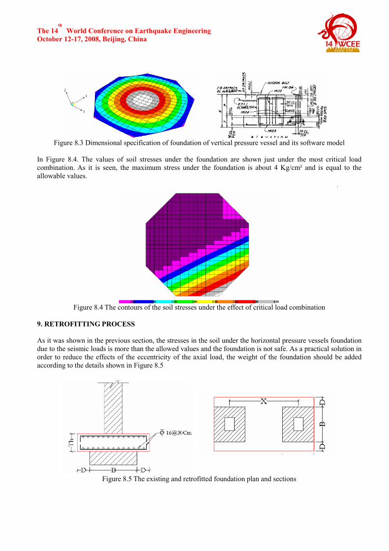
Figure 8.3 Dimensional specification of foundation of vertical pressure vessel and its software model
In Figure 8.4. The values of soil stresses under the foundation are shown just under the most critical load combination. As it is seen, the maximum stress under the foundation is about 4 Kg/cm² and is equal to the allowable values.
.
Figure 8.4 The contours of the soil stresses under the effect of critical load combination 9. RETROFITTING PROCESS
As it was shown in the previous section, the stresses in the soil under the horizontal pressure vessels foundation due to the seismic loads is more than the allowed values and the foundation is not safe. As a practical solution in order to reduce the effects of the eccentricity of the axial load, the weight of the foundation should be added according to the details shown in Figure 8.5
Figure 8.5 The existing and retrofitted foundation plan and sections

The 14th
World Conference on Earthquake Engineering October 12-17, 2008, Beijing, China
9.1. Re-controlling the soil stresses under retrofitted foundation In Figure 8.6, the quantities of the stress in the soil under the foundation are shown according to the most critical load combination. As it is shown, the maximum stress under the foundation due to the most critical load combination is about 3.15 Kg/cm² that are less than the maximum value, 4 Kg/cm² and it is safe.
.
Figure 8.6 The contours of soil stress under the effect of critical load combination
According to the results that is obtained and retrofitting the foundation, the stresses in the soil is in a good condition and it is safe.
10. CONCLUSION
With the investigation of the results that is obtained from seismic evaluation and analysis of the vessels, it is found that the shell of horizontal and vertical pressure vessels due to seismic forces is not vulnerable, and the static design of the vessels according to the thermal loads and internal pressure is adequate. There is a point for horizontal vessel that in most cases the stresses in the connection place of the saddle shaped support of the vessel due to seismic load combination is high, there for it should be controlled. Also in horizontal vessel the capacity of connection of the vessel to the concrete foundation should be checked. This connection is done with the aids of bolts which should be controlled. In most cases the stresses in the soil under the foundation should be
checked and compared to the allowable values.
For vertical pressure vessels the main problem is overturning of the vessels. Besides the effect of stresses due to overturning in the shell at the connection to the pedestal should be investigated and the results should be compared to the allowable values.
REFERENCES
1- American Institute of Steel Construction, Chicago, IL, (1989), AISC, Manual of Steel Construction – Allowable Stress Design 2- American Petroleum Institute, July (1993), API 650, Welded Steel Tanks for Oil Storage, 9th Edition 3-, American Society of Civil Engineers, Committee on Gas and Liquid Fuel Lifelines, New York, (1984), ASCE, Guidelines for the Seismic Design of Oil and Gas Pipeline Systems. 4- American Society of Mechanical Engineers, (1993), ASME B31.3, Chemical Plant Petroleum Refinery Piping (ASME B31.3). 5-American society of Mechanical Engineers, (1992), ASME, Boiler and Vessel Code 6-Iranina code of practice for seismic resistant design of buildings (standard no 2800),(2005),building and housing research center. 7- High Pressure Gas Institute of Japan (KHK), (2003), Seismic Design Standard for the Pressure Gas Facilities