seismic evaluation and retrofitting of existing hospital...
TRANSCRIPT
Open Journal of Civil Engineering, 2014, 4, 159-172 Published Online June 2014 in SciRes. http://www.scirp.org/journal/ojce http://dx.doi.org/10.4236/ojce.2014.42014
How to cite this paper: Hassaballa, A.E., Ismaeil, M.A. and Adam, F.M. (2014) Seismic Evaluation and Retrofitting of Existing Hospital Building in the Sudan. Open Journal of Civil Engineering, 4, 159-172. http://dx.doi.org/10.4236/ojce.2014.42014
Seismic Evaluation and Retrofitting of Existing Hospital Building in the Sudan
A. E. Hassaballa1, M. A. Ismaeil2, Fathelrahman M. Adam3 1Civil Engineering Department, Jazan University, Jazan, KSA (On Leave from Sudan University of Science and Technolog, Khartoum, Sudan) 2King Khalid University, Abha, KSA (On Leave from Sudan University of Science and Technology, Khartoum, Sudan) 3Department of Civil Engineering, Jazan University, Jazan, KSA (On Leave from Nile Valley University, Atbara, Sudan) Email: [email protected], [email protected], [email protected] Received 9 April 2014; revised 2 May 2014; accepted 24 May 2014
Copyright © 2014 by authors and Scientific Research Publishing Inc. This work is licensed under the Creative Commons Attribution International License (CC BY). http://creativecommons.org/licenses/by/4.0/
Abstract
Sudan is not free from earthquakes. It has experienced many earthquakes during the recent his-tory, and the previous studies on this field demonstrated this argument. This paper focuses on the study of seismic performance of existing hospital buildings in Sudan. The paper focused on study-ing design of reinforced concrete columns of a hospital building considering two load cases; case one is the design load including combinations of dead, live and wind loads and case two includes dead, live and seismic loads. The building was designed according to the Regulation of Egyptian Society for Earthquake Engineering (ESEE), using the linear static method (equivalent static me-thod). The analysis and design were performed using the SAP2000 version 14 software package. The design results obtained from the two cases of loading were compared observing that the de-sign based on case one was unsafe to withstand the additional load came from earthquake, be-cause the cross sections and area of steel for the most of building columns are under the required values that needed to resist the loads of case two. If the building is constructed according to the design using the loadings of case one, this situation needs remedy. This paper suggested two solu-tions for this problem based on strengthening the weak columns by inserting reinforced concrete shear walls in the direction of y axis affected by seismic load. Solution one suggests shear walls of length 2.5 m with different wall thicknesses (15 cm, 20 cm, 25 cm and 30 cm), whereas solution two suggests shear walls of length 4.5 m and 15 cm width. It was found that solution one solved the problem partially because some columns were still unsafe, but solution two solved the problem completely and all columns were safe.
Keywords
Seismic Loads, Retrofitting, RC Building Design, Shear Walls
A. E. Hassaballa et al.
160
1. Introduction
An earthquake is the vibration of the earth’s surface that follows a sudden release of energy in the crust. During an earthquake, the ground surface moves in all directions. The most damaging effects on buildings are caused by lateral movements which disturb the stability of the structure, causing it to topple or to collapse sideways. Since buildings are normally constructed to resist gravity, many traditional systems of construction are not inherently resistant to horizontal forces. Thus design for earthquakes consists largely of solving the problem of building vibrations.
The design of buildings is fundamentally concerned with ensuring that the components of buildings, e.g. lat-eral force-resisting system, can adequately serve their intended functions. In the case of seismic design of the lateral force-resisting system, the design problem can be reduced simply to the problem of providing adequate force and deformation capacity to resist the seismic demands. Seismic Analysis is a subset of structural analysis and is the calculation of the response of a building structure to earthquakes. It is a part of the process of structur-al design, earthquake engineering or structural assessment and retrofit in regions where earthquakes are preva-lent. Seismic structural analysis methods can be divided into two main categories, static analysis and dynamic analysis. These two main categories can be divided into two main types of analysis, the linear and non-linear analysis. The studied building in this paper is a typical three-story model of a hospital building located in the Sudan. The building is comprised of a reinforced concrete structural frame with infill masonry walls. The struc-ture members are made of in-situ reinforced concrete. The overall plan dimension is 21.5 m × 13 m with 9.6 m in height. The floor is a flat slab system.
There are many researches carried out in this area, such as: Rex, Ventura and Prion (2000) [1] recently have proposed a “multi-angle strip model” for steel plate shear walls. Using a non-linear analysis program, the re-searchers have shown that the predictions of analyses are reasonable close to the test results. Mahmoud REZAI et.al., (2004) [2] demonstrated finite element models of steel plate shear walls as an effective and economical lateral bracing system testing a 4 storey specimen at the University of British Columbia (UBC) to assess the ability of current analysis techniques to reasonably describe the behaviour observed during the experiment. The results of this investigation showed that the simplified and detailed analytical models overpredicted the elastic stiffness of the test specimen. The yield and ultimate strength as well as post-buckling behaviour of the speci-men were reasonably well predicted. H. Sucuoglu et al., (2006) [3] developed retrofit solutions for the residen-tial building stocks in Istanbul selecting residential midrise apartment buildings under high seismic risk. The study reveals that feasible retrofit solutions can be developed for the high risk building stock in Istanbul. Exte-rior retrofit solutions with perimeter coupled shear walls prevail in feasibility, with less cost and downtime. M. Di Ludovico et al. (2008) [4] presented a paper dealing with full-scale tests of an under-designed RC structure retrofitted with two different techniques: FRP wrapping of columns and joints and RC jacketing of selected ver-tical elements. Theoretical pushover analyses were conducted on both the retrofitted configurations in order to predict the seismic structural behaviour. By the experimental activity conducted on the structure the paper con-cluded that: • FRP laminates intervention (by columns ends wrapping and preventing brittle mechanisms) is a ductility
based rehabilitation system: it provided a ductility increase equal to about 123% without varying the struc-tural hierarchy of strength and the elastic period of the structure; it does not affect the torsional behaviour of the structure.
• RC jacketing intervention is a strength-ductility based rehabilitation system: it provided a ductility increase equal to about 76% and a strength increase equal to about 43% with an elastic period decrease of about 25%; it allowed reducing the torsional behaviour of the structure by a factor of about 56%. This scheme was strongly effective in mitigating the torsional effects and increasing the seismic performance of the “as-built” structure. Londhe and A.P. Chavan (2010) [5] presented a paper on “behaviour of building frames with steel plates shear walls” to describe the analysis of high-rise steel buildings frames with Steel plate shear walls (SPSWs) by using SAP 2000 FEA program using thickness of plate (5 mm to 10 mm) and aspect ratio (0.833 to 1.667 width-to-height ratio). From the results obtained it is observed that, with the use of steel shear walls in the buildings, the bending moments in the beams are observed to reduce. The increase of shear wall thickness has a little effect on the bending moments and shear forces of the beams and there is small decrease in the lateral deflections. The storey drift increases with increase of aspect ratio while bending moment and shear force show a considerable increase. M. A. Ismaeil et al., (2013) [6] carried out a paper on Assessment
A. E. Hassaballa et al.
161
of Seismic Performance and Strengthening of RC Existing Residual Buildings in the Sudan. The objective of this paper is to assess the seismic performance of existing residual buildings in the Sudan. One case study has been chosen for this purpose. The evaluation has proved that the columns of four-story residual buildings are not seismically safe. A comparative study has been done to choose a suitable strengthening method. An effective method has been proposed by adding RC shear walls. Three cases of same positions for the shear walls with thicknesses of 20 cm, 15 cm and 10 cm have been examined. It has been proved that RC wall with 15 cm thickness is suitable strategy for this case to reduce the seismic vulnerability of exiting (RC) buildings in Sudan. M.A. Ismaeil and A. E. Hassaballa (2013) [7] conducted “Seismic Retrofitting of a RC Building by Adding Steel Plate Shear Walls” using equivalent static method with the aid of SAP2000 program. One type of reinforced concrete existing residual buildings in Khartoum city, was selected for evaluation as a case study. The retrofitting of building was done by using steel plate shear walls with thicknesses of 5 mm, 7 mm and 10 mm. From the results obtained, it was found that the use of two additional SPSWs with 7 mm thick-ness placed at the internal frame of the existing system, resulted in a reduction of bending moments in the columns and beams.
2. Analysis and Design of Model
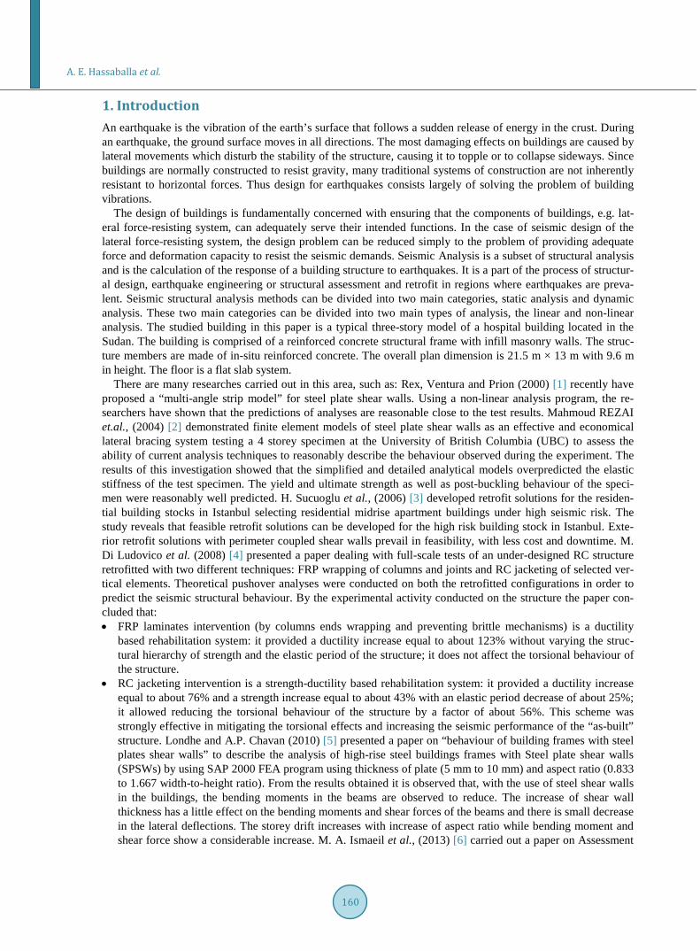
The analysis and design of building were done using SAP2000 version 14 [8]. This software package is from Computers and Structures which the analysis is based on the finite element method. The software has the capa-bility of designing and optimizing building structures. Among the features introduced by the analysis engine of SAP2000 are static and dynamic analysis, linear and nonlinear analysis, and pushover analysis. The analytical modeling used in this software is the member type model which means that beams or columns are modeled us-ing single elements. The building also was designed by using (ISACOL) software [9] and this done only for Load case combining Dead Load and Live Load. The executed model done by SAP2000 is shown in Figure 1 and Figure 2.
The following assumptions were considered: • The cross section of beam and column members were input according to the original design data. • The walls with brick material were modeled with shell element in order to consider out-of-plane stiffness. • The building was modeled as 3-D frames with fixed supports at the foundation level.
The lateral force resisting system consists of moment resisting frames without shear walls. The rectangular shapes were used for the columns. Columns and beams sizes along the building height are listed in Table 1 and Table 2.
Figure 1. Model of a 3-story hospital building.
A. E. Hassaballa et al.
162
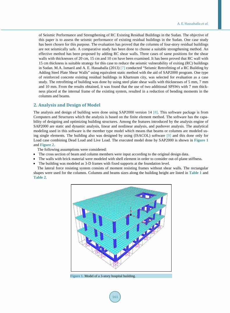
Figure 2. Plan of the building and labeling of columns. Table 1. The cross sections of columns.
The cross sections of columns Story No. 300 × 500 Ground floor 300 × 500 First floor 300 × 500 Second floor
Table 2. The cross sections of beams.
The cross sections of beams Story No. 300 × 500 Ground floor 300 × 500 First floor 300 × 500 Second floor
The model was analyzed for gravity and seismic loads using SAP2000. The design generated according to the
requirements of British Standards BS8110-1997 [10]. The material properties are summarized below.
• The characteristic concrete compressive strength (fcu) at 28 days for all concrete elements was taken to be 25 N/mm2.
• The yield stress for steel bars fy was taken 460 N/mm2 and for stirrups 250 N/mm2. • The unit weight of concrete was taken as 24 kN/m3. • The Poisson's ratio for concrete was taken as 0.2. • The unit weight of masonry was taken as 19 kN/m3 [11]. • Concrete cover to steel reinforcement shall be provided to protect the reinforcement against corrosion and
fire as per BS8110 [10]. The clear concrete cover shall be as following: 1) concrete permanently exposed to soil = 75 mm 2) Slabs = 25 mm 3) Beams and columns = 30 mm.
3. Design Loads
3.1. Gravity Loads
The loads on model are taken according to the BS8110-1997. Dead load consists of self-weight of slabs, flooring for a typical frame, flooring for the roof and internal partitions. The live load was taken to be 3 and 4 kN/m2, and 1.5 kN/m2 for the floor finishing load. It should be noted that SAP2000 analysis program automatically esti-
A. E. Hassaballa et al.
163
mates the own weight of the structural elements and include it in the elastic analysis.
3.2. Wind Loads
The British Standard BS 6399 [12] gives methods for determining the gust peak wind loads on buildings and its components thereof the wind load should be taken into account in design using equivalent static procedures. For the city of Khartoum the basic wind speed (V) is 100 mile/hour (44.4 m/sec).
3.3. Load Combinations
The load combinations used in design of the model follow the Code using equations (1 to 5) [10]. The sustained live load associated with lateral load combinations is 25% of the total live load.
1.40 DL (1) 1.40 DL 1.60 LL+ (2)
1.00 DL 1.40 WL+ (3) 1.40 DL 1.40 WL+ (4)
1.20 DL 1.20 LL 1.20 WL+ + (5) where DL is the dead load, LL is the live load, WL is the wind load.
4. Design of Columns before Adding Seismic Loads
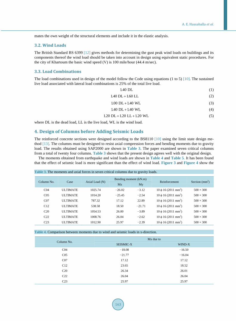
The reinforced concrete sections were designed according to the BS8110 [10] using the limit state design me-thod [13]. The columns must be designed to resist axial compression forces and bending moments due to gravity load. The results obtained using SAP2000 are shown in Table 3. The paper examined seven critical columns from a total of twenty four columns. Table 3 shows that the present design agrees well with the original design.
The moments obtained from earthquake and wind loads are shown in Table 4 and Table 5. It has been found that the effect of seismic load is more significant than the effect of wind load. Figure 3 and Figure 4 show the Table 3. The moments and axial forces in seven critical columns due to gravity loads.
Column No. Case Axial Load (N) Bending moment (kN.m)
Reinforcement Section (mm2) Mx My
C04 ULTIMATE 1025.74 −26.02 −3.12 10 ϕ 16 (2011 mm2) 500 × 300
C05 ULTIMATE 1014.20 −25.45 −2.54 10 ϕ 16 (2011 mm2) 500 × 300
C07 ULTIMATE 787.32 17.12 22.89 10 ϕ 16 (2011 mm2) 500 × 300
C12 ULTIMATE 538.58 18.50 −21.71 10 ϕ 16 (2011 mm2) 500 × 300
C20 ULTIMATE 1054.53 26.00 −3.89 10 ϕ 16 (2011 mm2) 500 × 300
C22 ULTIMATE 1008.76 26.04 −2.62 10 ϕ 16 (2011 mm2) 500 × 300
C23 ULTIMATE 1012.90 25.97 −2.39 10 ϕ 16 (2011 mm2) 500 × 300
Table 4. Comparison between moments due to wind and seismic loads in x-direction.
Column No. Mx due to
SEISMIC-X WIND-X
C04 −18.08 −16.50 C05 −21.77 −16.04 C07 17.12 17.12
C12 23.65 18.52
C20 26.34 26.01
C22 26.04 26.04
C23 25.97 25.97
A. E. Hassaballa et al.
164
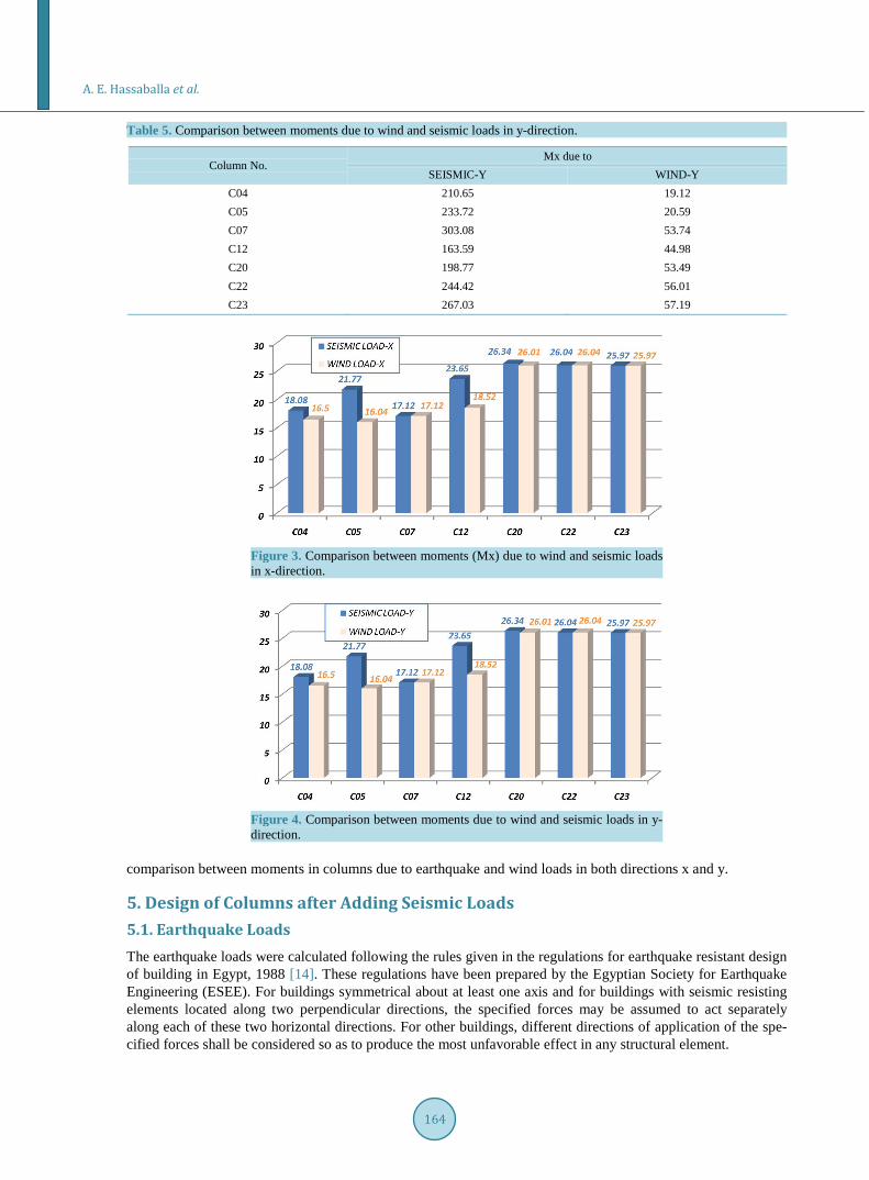
Table 5. Comparison between moments due to wind and seismic loads in y-direction.
Column No. Mx due to
SEISMIC-Y WIND-Y C04 210.65 19.12 C05 233.72 20.59 C07 303.08 53.74 C12 163.59 44.98 C20 198.77 53.49 C22 244.42 56.01 C23 267.03 57.19
Figure 3. Comparison between moments (Mx) due to wind and seismic loads in x-direction.
Figure 4. Comparison between moments due to wind and seismic loads in y- direction.
comparison between moments in columns due to earthquake and wind loads in both directions x and y.
5. Design of Columns after Adding Seismic Loads
5.1. Earthquake Loads
The earthquake loads were calculated following the rules given in the regulations for earthquake resistant design of building in Egypt, 1988 [14]. These regulations have been prepared by the Egyptian Society for Earthquake Engineering (ESEE). For buildings symmetrical about at least one axis and for buildings with seismic resisting elements located along two perpendicular directions, the specified forces may be assumed to act separately along each of these two horizontal directions. For other buildings, different directions of application of the spe-cified forces shall be considered so as to produce the most unfavorable effect in any structural element.
A. E. Hassaballa et al.
165
5.2. Load Combinations
The load combinations used in the design of the RC hospital buildings follow the Egyptian Code for Design and Construction of RC Structures [15]. The sustained live load associated with lateral load combinations is 25% of the total live load. These load combinations are:
U1 1.4D 1.6L= + (6)
( )U2 0.8 1.4D 1.6L 1.6W= + + (7)
( )U3 0.8 1.4D 1.6L 1.6S= + + (8)
U4 0.9D 1.3W= + (9) U5 0.9D 1.3S= + (10)
where D is the dead load, L is the live load, W is the wind load, and S is the seismic load.
5.3. Total Horizontal Seismic Force
Using the static lateral force procedure and according to Regulations of the Egyptian Society for Earthquake Engineering (ESEE 1988) [14] every building shall be designed and constructed to withstand a total horizontal seismic force (V) in each direction under consideration in accordance with the following formula: According to Clause 2.3.2.1 of the (ESEE) Regulations, the total horizontal seismic force V is given by:
V Cs Wt= (11) where:
Cs is the seismic design coefficient and shall be determined according to Clause 2.3.2.2 in Reference [14], Wt is the total weight.
The seismic design coefficient Cs shall be determined from: Cs = Z I S M R Q (12)
where: Z is the seismic zoning factor I is the importance factor S is the structural system type factor (the value of S shall be determined separately for each direction). M is the material factor R is the risk factor (where two values of R apply, the higher shall be used). Q is the construction quality factor. The seismic zoning factor (Z) shall be determined from:
Z A C F= (13) in which :
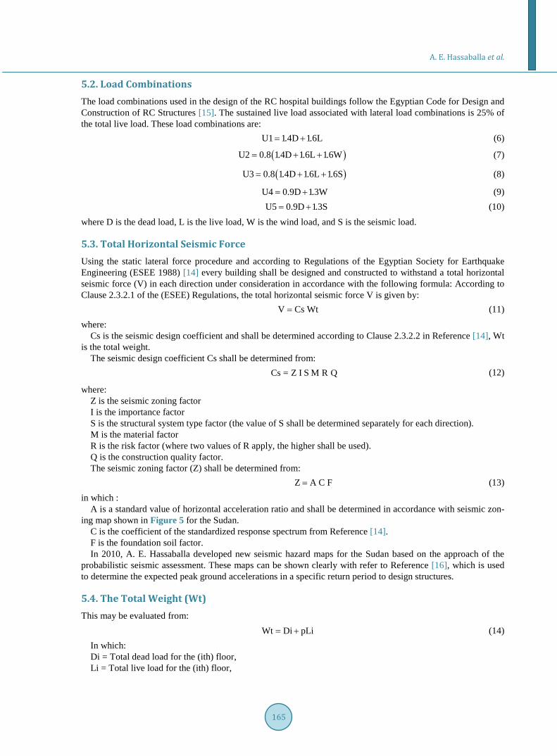
A is a standard value of horizontal acceleration ratio and shall be determined in accordance with seismic zon-ing map shown in Figure 5 for the Sudan.
C is the coefficient of the standardized response spectrum from Reference [14]. F is the foundation soil factor. In 2010, A. E. Hassaballa developed new seismic hazard maps for the Sudan based on the approach of the
probabilistic seismic assessment. These maps can be shown clearly with refer to Reference [16], which is used to determine the expected peak ground accelerations in a specific return period to design structures.
5.4. The Total Weight (Wt)
This may be evaluated from: Wt Di pLi= + (14)
In which: Di = Total dead load for the (ith) floor, Li = Total live load for the (ith) floor,
A. E. Hassaballa et al.
166
Figure 5. Distribution of horizontal seismic force.
p = Incidence factor for live loads, given in Table 5 [14]. For buildings in which the total horizontal force is resisted by a moment resisting space frame the value of (T)
may be given by: T 0. 1n= (15)
In which (n) is the total number of stories above the base.
5.5. Distribution of Horizontal Seismic Forces
For a regular building the total horizontal seismic force (V) shall be distributed over the height of the building in accordance with the following formula:
( )i ii t
i i1
h wF V F
w hni=
= −∑
(16)
where: hi is the height over the base to the level of the (ith) floor. wi is the total load on the (ith) floor determined according to Equation (14). V is the total horizontal seismic force. Fi is the part of the total horizontal seismic force assigned to the (ith) floor. Ft is that additional concentrated force at top story and shall be determined as follows: Ft = 0.0 for (H/d) less than 3.0 m. Ft = 0.1V for (H/d) more than or equal to 3.0. Ft = 0.2V For chimneys and smoke-stacks resting on the ground,
where (H/d) is the height to width ratio of the building) n is the total number of stories above the base of the building. 1) Calculation of base shear The analysis for gravity loads yielded a total floor weight of 12634.05 kN. The equivalent lateral force procedure of (ESEE 1988) was used to calculate the design base shear. The re-
sulting seismic coefficient, Cs, was determined to be 0.26 and the corresponding base shear was approximately 3300 kN.
2) Distribution of horizontal seismic force The period of the building was the same in both directions. Hence, the loads in the E-W direction are the same
A. E. Hassaballa et al.
167
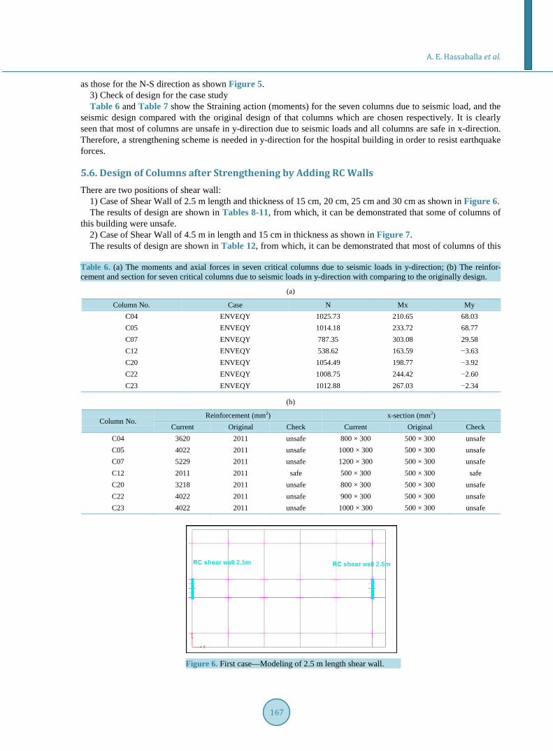
as those for the N-S direction as shown Figure 5. 3) Check of design for the case study Table 6 and Table 7 show the Straining action (moments) for the seven columns due to seismic load, and the
seismic design compared with the original design of that columns which are chosen respectively. It is clearly seen that most of columns are unsafe in y-direction due to seismic loads and all columns are safe in x-direction. Therefore, a strengthening scheme is needed in y-direction for the hospital building in order to resist earthquake forces.
5.6. Design of Columns after Strengthening by Adding RC Walls
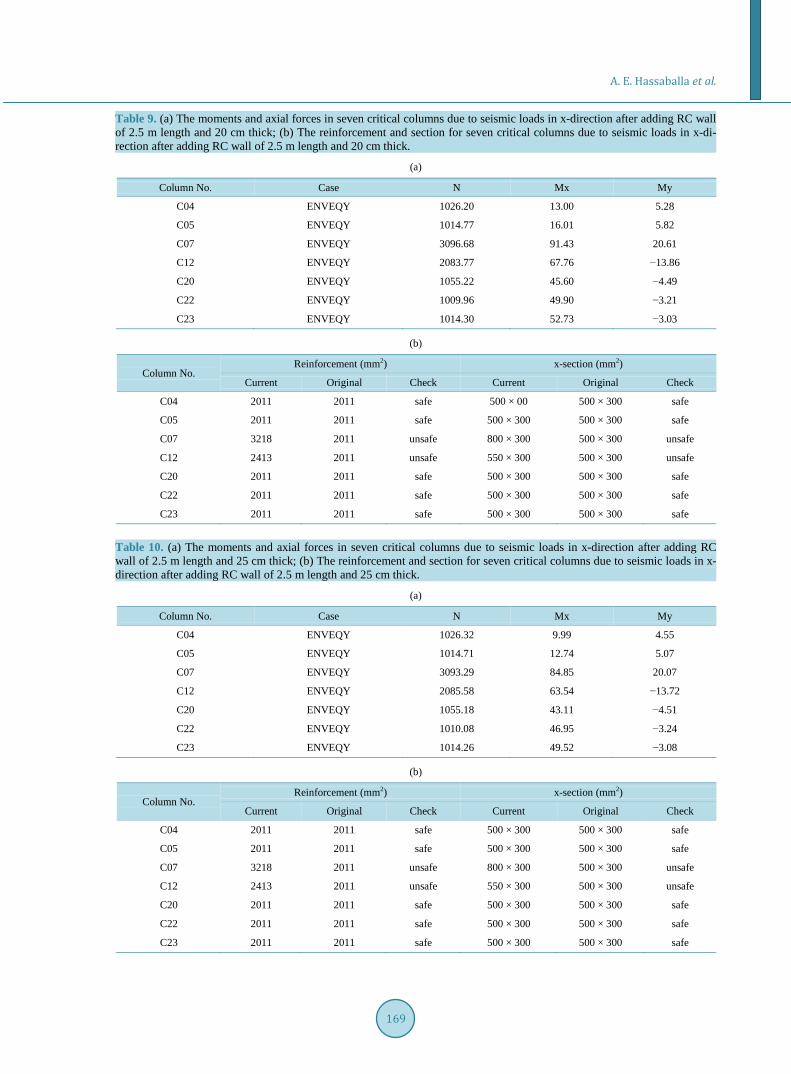
There are two positions of shear wall: 1) Case of Shear Wall of 2.5 m length and thickness of 15 cm, 20 cm, 25 cm and 30 cm as shown in Figure 6. The results of design are shown in Tables 8-11, from which, it can be demonstrated that some of columns of
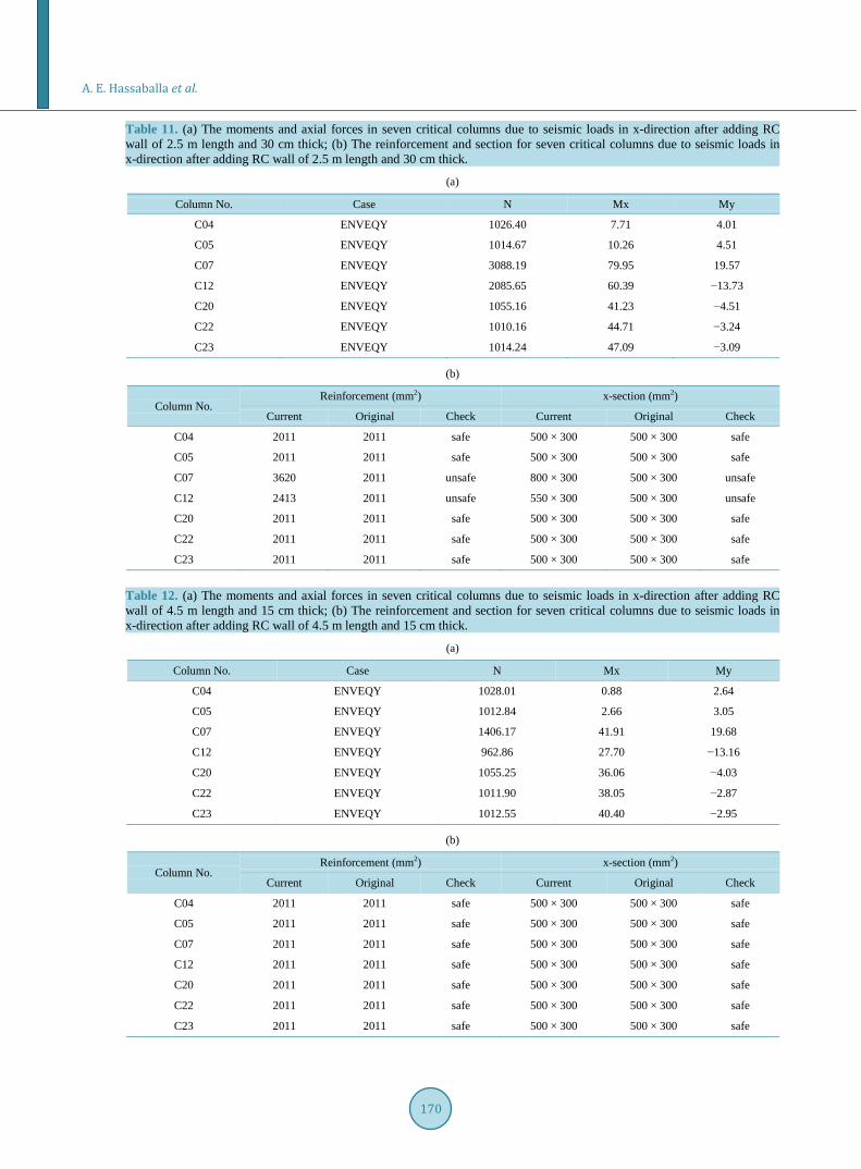
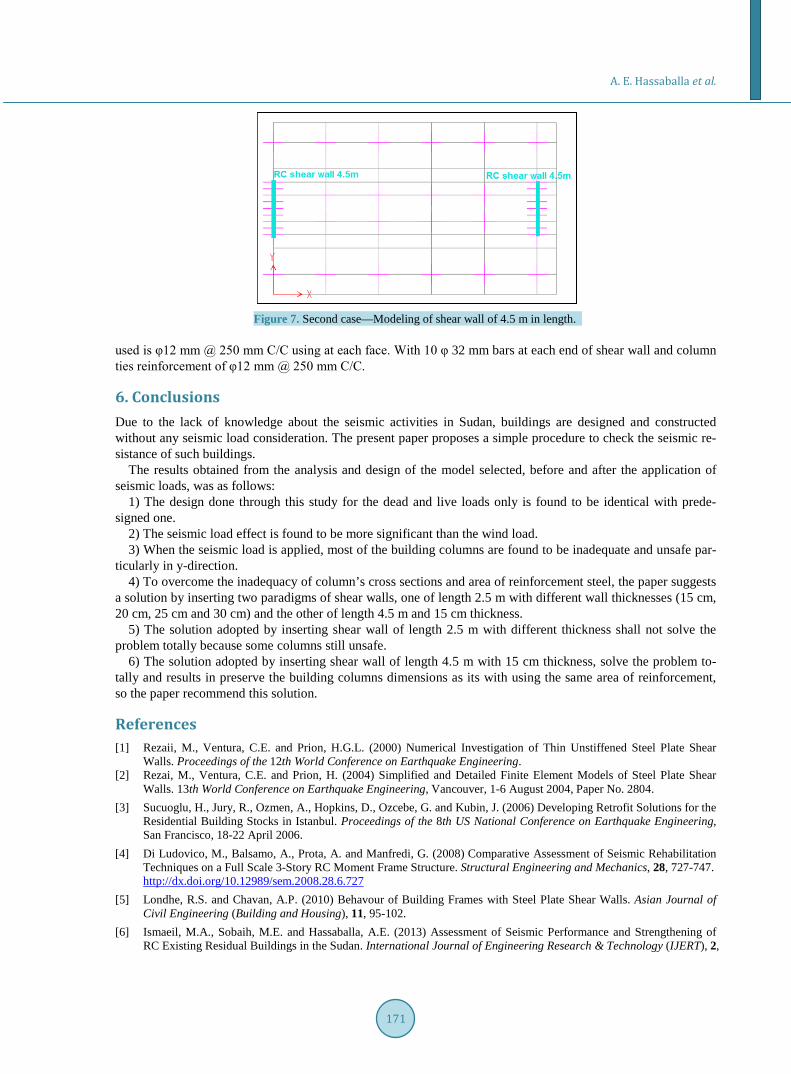
this building were unsafe. 2) Case of Shear Wall of 4.5 m in length and 15 cm in thickness as shown in Figure 7. The results of design are shown in Table 12, from which, it can be demonstrated that most of columns of this
Table 6. (a) The moments and axial forces in seven critical columns due to seismic loads in y-direction; (b) The reinfor- cement and section for seven critical columns due to seismic loads in y-direction with comparing to the originally design.
(a)
Column No. Case N Mx My C04 ENVEQY 1025.73 210.65 68.03 C05 ENVEQY 1014.18 233.72 68.77 C07 ENVEQY 787.35 303.08 29.58 C12 ENVEQY 538.62 163.59 −3.63 C20 ENVEQY 1054.49 198.77 −3.92 C22 ENVEQY 1008.75 244.42 −2.60 C23 ENVEQY 1012.88 267.03 −2.34
(b)
Column No. Reinforcement (mm2) x-section (mm2)
Current Original Check Current Original Check C04 3620 2011 unsafe 800 × 300 500 × 300 unsafe C05 4022 2011 unsafe 1000 × 300 500 × 300 unsafe C07 5229 2011 unsafe 1200 × 300 500 × 300 unsafe C12 2011 2011 safe 500 × 300 500 × 300 safe C20 3218 2011 unsafe 800 × 300 500 × 300 unsafe C22 4022 2011 unsafe 900 × 300 500 × 300 unsafe C23 4022 2011 unsafe 1000 × 300 500 × 300 unsafe
Figure 6. First case—Modeling of 2.5 m length shear wall.
A. E. Hassaballa et al.
168
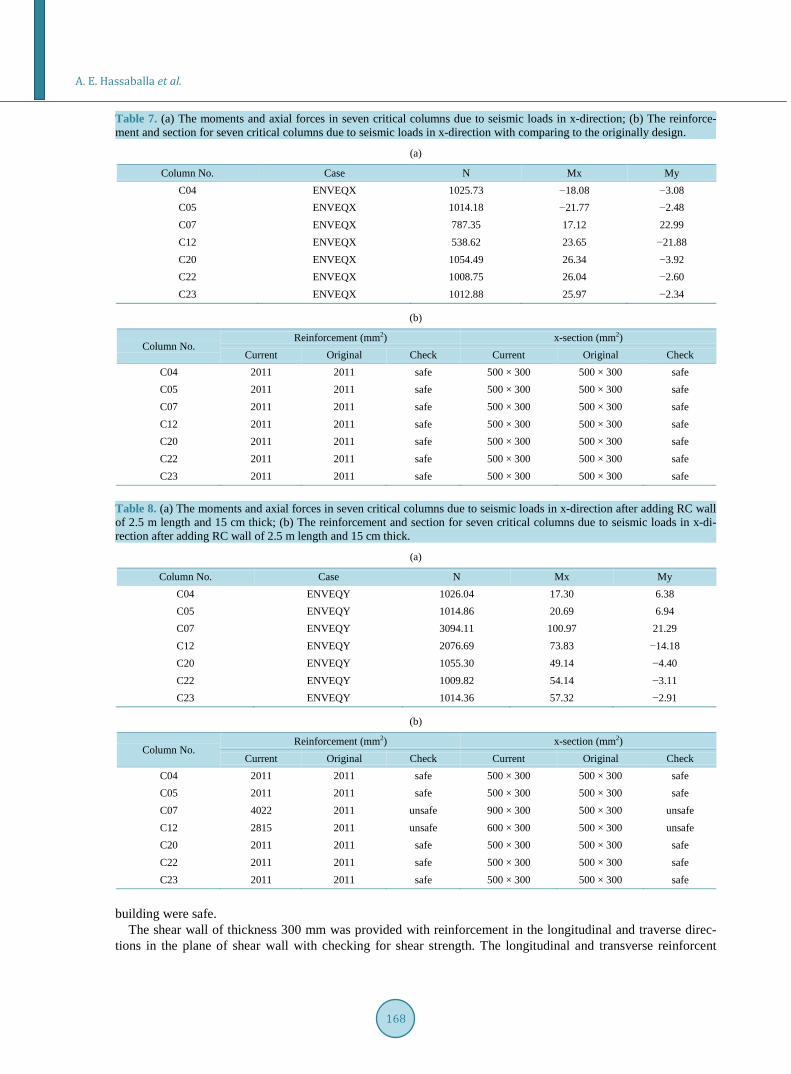
Table 7. (a) The moments and axial forces in seven critical columns due to seismic loads in x-direction; (b) The reinforce- ment and section for seven critical columns due to seismic loads in x-direction with comparing to the originally design.
(a)
Column No. Case N Mx My C04 ENVEQX 1025.73 −18.08 −3.08 C05 ENVEQX 1014.18 −21.77 −2.48 C07 ENVEQX 787.35 17.12 22.99 C12 ENVEQX 538.62 23.65 −21.88 C20 ENVEQX 1054.49 26.34 −3.92 C22 ENVEQX 1008.75 26.04 −2.60 C23 ENVEQX 1012.88 25.97 −2.34
(b)
Column No. Reinforcement (mm2) x-section (mm2)
Current Original Check Current Original Check C04 2011 2011 safe 500 × 300 500 × 300 safe C05 2011 2011 safe 500 × 300 500 × 300 safe C07 2011 2011 safe 500 × 300 500 × 300 safe C12 2011 2011 safe 500 × 300 500 × 300 safe C20 2011 2011 safe 500 × 300 500 × 300 safe C22 2011 2011 safe 500 × 300 500 × 300 safe C23 2011 2011 safe 500 × 300 500 × 300 safe
Table 8. (a) The moments and axial forces in seven critical columns due to seismic loads in x-direction after adding RC wall of 2.5 m length and 15 cm thick; (b) The reinforcement and section for seven critical columns due to seismic loads in x-di- rection after adding RC wall of 2.5 m length and 15 cm thick.
(a)
Column No. Case N Mx My C04 ENVEQY 1026.04 17.30 6.38 C05 ENVEQY 1014.86 20.69 6.94 C07 ENVEQY 3094.11 100.97 21.29 C12 ENVEQY 2076.69 73.83 −14.18 C20 ENVEQY 1055.30 49.14 −4.40 C22 ENVEQY 1009.82 54.14 −3.11 C23 ENVEQY 1014.36 57.32 −2.91
(b)
Column No. Reinforcement (mm2) x-section (mm2)
Current Original Check Current Original Check C04 2011 2011 safe 500 × 300 500 × 300 safe C05 2011 2011 safe 500 × 300 500 × 300 safe C07 4022 2011 unsafe 900 × 300 500 × 300 unsafe C12 2815 2011 unsafe 600 × 300 500 × 300 unsafe C20 2011 2011 safe 500 × 300 500 × 300 safe C22 2011 2011 safe 500 × 300 500 × 300 safe C23 2011 2011 safe 500 × 300 500 × 300 safe
building were safe.
The shear wall of thickness 300 mm was provided with reinforcement in the longitudinal and traverse direc-tions in the plane of shear wall with checking for shear strength. The longitudinal and transverse reinforcent
A. E. Hassaballa et al.
169
Table 9. (a) The moments and axial forces in seven critical columns due to seismic loads in x-direction after adding RC wall of 2.5 m length and 20 cm thick; (b) The reinforcement and section for seven critical columns due to seismic loads in x-di- rection after adding RC wall of 2.5 m length and 20 cm thick.
(a)
Column No. Case N Mx My
C04 ENVEQY 1026.20 13.00 5.28
C05 ENVEQY 1014.77 16.01 5.82
C07 ENVEQY 3096.68 91.43 20.61
C12 ENVEQY 2083.77 67.76 −13.86
C20 ENVEQY 1055.22 45.60 −4.49
C22 ENVEQY 1009.96 49.90 −3.21
C23 ENVEQY 1014.30 52.73 −3.03
(b)
Column No. Reinforcement (mm2) x-section (mm2)
Current Original Check Current Original Check
C04 2011 2011 safe 500 × 00 500 × 300 safe
C05 2011 2011 safe 500 × 300 500 × 300 safe
C07 3218 2011 unsafe 800 × 300 500 × 300 unsafe
C12 2413 2011 unsafe 550 × 300 500 × 300 unsafe
C20 2011 2011 safe 500 × 300 500 × 300 safe
C22 2011 2011 safe 500 × 300 500 × 300 safe
C23 2011 2011 safe 500 × 300 500 × 300 safe
Table 10. (a) The moments and axial forces in seven critical columns due to seismic loads in x-direction after adding RC wall of 2.5 m length and 25 cm thick; (b) The reinforcement and section for seven critical columns due to seismic loads in x- direction after adding RC wall of 2.5 m length and 25 cm thick.
(a)
Column No. Case N Mx My
C04 ENVEQY 1026.32 9.99 4.55
C05 ENVEQY 1014.71 12.74 5.07
C07 ENVEQY 3093.29 84.85 20.07
C12 ENVEQY 2085.58 63.54 −13.72
C20 ENVEQY 1055.18 43.11 −4.51
C22 ENVEQY 1010.08 46.95 −3.24
C23 ENVEQY 1014.26 49.52 −3.08
(b)
Column No. Reinforcement (mm2) x-section (mm2)
Current Original Check Current Original Check
C04 2011 2011 safe 500 × 300 500 × 300 safe
C05 2011 2011 safe 500 × 300 500 × 300 safe
C07 3218 2011 unsafe 800 × 300 500 × 300 unsafe
C12 2413 2011 unsafe 550 × 300 500 × 300 unsafe
C20 2011 2011 safe 500 × 300 500 × 300 safe
C22 2011 2011 safe 500 × 300 500 × 300 safe
C23 2011 2011 safe 500 × 300 500 × 300 safe
A. E. Hassaballa et al.
170
Table 11. (a) The moments and axial forces in seven critical columns due to seismic loads in x-direction after adding RC wall of 2.5 m length and 30 cm thick; (b) The reinforcement and section for seven critical columns due to seismic loads in x-direction after adding RC wall of 2.5 m length and 30 cm thick.
(a)
Column No. Case N Mx My
C04 ENVEQY 1026.40 7.71 4.01
C05 ENVEQY 1014.67 10.26 4.51
C07 ENVEQY 3088.19 79.95 19.57
C12 ENVEQY 2085.65 60.39 −13.73
C20 ENVEQY 1055.16 41.23 −4.51
C22 ENVEQY 1010.16 44.71 −3.24
C23 ENVEQY 1014.24 47.09 −3.09
(b)
Column No. Reinforcement (mm2) x-section (mm2)
Current Original Check Current Original Check
C04 2011 2011 safe 500 × 300 500 × 300 safe
C05 2011 2011 safe 500 × 300 500 × 300 safe
C07 3620 2011 unsafe 800 × 300 500 × 300 unsafe
C12 2413 2011 unsafe 550 × 300 500 × 300 unsafe
C20 2011 2011 safe 500 × 300 500 × 300 safe
C22 2011 2011 safe 500 × 300 500 × 300 safe
C23 2011 2011 safe 500 × 300 500 × 300 safe
Table 12. (a) The moments and axial forces in seven critical columns due to seismic loads in x-direction after adding RC wall of 4.5 m length and 15 cm thick; (b) The reinforcement and section for seven critical columns due to seismic loads in x-direction after adding RC wall of 4.5 m length and 15 cm thick.
(a)
Column No. Case N Mx My
C04 ENVEQY 1028.01 0.88 2.64
C05 ENVEQY 1012.84 2.66 3.05
C07 ENVEQY 1406.17 41.91 19.68
C12 ENVEQY 962.86 27.70 −13.16
C20 ENVEQY 1055.25 36.06 −4.03
C22 ENVEQY 1011.90 38.05 −2.87
C23 ENVEQY 1012.55 40.40 −2.95
(b)
Column No. Reinforcement (mm2) x-section (mm2)
Current Original Check Current Original Check
C04 2011 2011 safe 500 × 300 500 × 300 safe
C05 2011 2011 safe 500 × 300 500 × 300 safe
C07 2011 2011 safe 500 × 300 500 × 300 safe
C12 2011 2011 safe 500 × 300 500 × 300 safe
C20 2011 2011 safe 500 × 300 500 × 300 safe
C22 2011 2011 safe 500 × 300 500 × 300 safe
C23 2011 2011 safe 500 × 300 500 × 300 safe
A. E. Hassaballa et al.
171
Figure 7. Second case—Modeling of shear wall of 4.5 m in length. used is φ12 mm @ 250 mm C/C using at each face. With 10 φ 32 mm bars at each end of shear wall and column ties reinforcement of φ12 mm @ 250 mm C/C.
6. Conclusions
Due to the lack of knowledge about the seismic activities in Sudan, buildings are designed and constructed without any seismic load consideration. The present paper proposes a simple procedure to check the seismic re-sistance of such buildings.
The results obtained from the analysis and design of the model selected, before and after the application of seismic loads, was as follows:
1) The design done through this study for the dead and live loads only is found to be identical with prede-signed one.
2) The seismic load effect is found to be more significant than the wind load. 3) When the seismic load is applied, most of the building columns are found to be inadequate and unsafe par-
ticularly in y-direction. 4) To overcome the inadequacy of column’s cross sections and area of reinforcement steel, the paper suggests
a solution by inserting two paradigms of shear walls, one of length 2.5 m with different wall thicknesses (15 cm, 20 cm, 25 cm and 30 cm) and the other of length 4.5 m and 15 cm thickness.
5) The solution adopted by inserting shear wall of length 2.5 m with different thickness shall not solve the problem totally because some columns still unsafe.
6) The solution adopted by inserting shear wall of length 4.5 m with 15 cm thickness, solve the problem to-tally and results in preserve the building columns dimensions as its with using the same area of reinforcement, so the paper recommend this solution.
References [1] Rezaii, M., Ventura, C.E. and Prion, H.G.L. (2000) Numerical Investigation of Thin Unstiffened Steel Plate Shear
Walls. Proceedings of the 12th World Conference on Earthquake Engineering. [2] Rezai, M., Ventura, C.E. and Prion, H. (2004) Simplified and Detailed Finite Element Models of Steel Plate Shear
Walls. 13th World Conference on Earthquake Engineering, Vancouver, 1-6 August 2004, Paper No. 2804. [3] Sucuoglu, H., Jury, R., Ozmen, A., Hopkins, D., Ozcebe, G. and Kubin, J. (2006) Developing Retrofit Solutions for the
Residential Building Stocks in Istanbul. Proceedings of the 8th US National Conference on Earthquake Engineering, San Francisco, 18-22 April 2006.
[4] Di Ludovico, M., Balsamo, A., Prota, A. and Manfredi, G. (2008) Comparative Assessment of Seismic Rehabilitation Techniques on a Full Scale 3-Story RC Moment Frame Structure. Structural Engineering and Mechanics, 28, 727-747. http://dx.doi.org/10.12989/sem.2008.28.6.727
[5] Londhe, R.S. and Chavan, A.P. (2010) Behavour of Building Frames with Steel Plate Shear Walls. Asian Journal of Civil Engineering (Building and Housing), 11, 95-102.
[6] Ismaeil, M.A., Sobaih, M.E. and Hassaballa, A.E. (2013) Assessment of Seismic Performance and Strengthening of RC Existing Residual Buildings in the Sudan. International Journal of Engineering Research & Technology (IJERT), 2,
A. E. Hassaballa et al.
172
442-450. www.ijert.org [7] Ismaeil, M.A. and Hassaballa, A.E. (2013) Seismic Retrofitting of a RC Building by Adding Steel Plate Shear Walls.
IOSR Journal of Mechanical and Civil Engineering (JOSR-JMCE), 7, 49-62. www.iosrjournals.org. [8] Computers and Structures. SAP2000® v.14: Three Dimensional Static and Dynamic Finite Element Analysis and de-
sign of Structures, Computers and Structures Inc., Berkeley, California, USA, 2007. [9] Shehata, A.Y. (1999) Information Systems Application on Reinforced Concrete Columns. M.Sc. Thesis, Faculty of
Engineering, Department of Structural Engineering, Cairo University, Giza. [10] BS 8110. (1997) The Structural Use of Concrete, British Standard Institution, London. [11] El-Hameed, M.H. (2007) Estimation of Dynamic Characteristics of Existing Common Reinforced Concrete Buildings
in Egypt Using Ambient Vibration Tests. M.Sc. Thesis, Faculty of Engineering, Department of Structural Engineering, Cairo University, Giza.
[12] Concrete BS6399 (1984) Design Loading for Building Part 1: Code of Practice for Dead and Imposed Loads. [13] Mosley, W.H. and Bungey, J.H. (1997) Reinforced Concrete Design; BS 8110: Part 1. 2nd Edition, Macmillan, Lon-
don. [14] (1988) Regulations for Earthquake-Resistance Design of Buildings in Egypt. Egyptian Society for Earthquake Engi-
neering (ESEE), Cairo. [15] ECP-201, Egyptian Code for Calculating Loads and Forces in Structural Work and Masonry, National Research Center
for Housing and Building, Giza, Egypt, 2011. [16] Hassaballa, E. (2010) Probabilistic Seismic Hazard Assessment and Seismic Design Provisions for Sudan. Ph.D. The-
sis, Sudan University of Science and Technology (SUST), Khartoum, Sudan.