seismic design of cast-in-place concrete diaphragms...
TRANSCRIPT

Seismic Design of Cast-in-Place Concrete
Diaphragms, Chords and Collectors
Pramin NorachanManager, Structural Engineering Unit
AIT Solutions
DESIGN OF TALL BUILDINGS: TRENDS AND ADVANCEMENTS FOR STRUCTURAL PEFORMANCE
Pathumthani, Thailand
November 10, 2016

Presentation Outline
1. Introduction
2. Overview of Structure
3. Analysis and Design Criteria
4. Force Scaling
5. Section Cuts
6. Forces from Section Cuts
7. Diaphragm Design


Pramin Norachan 4
• Estimating the inelastic properties for a real
component is not a simple task.
• If there is substantial inelastic behavior in an
actual structure, the results of an elastic
analysis may be of uncertain value for making
design decisions, and may even be
misleading.
• As a tool for obtaining information for design,
even a crude inelastic model can be more
useful than an elaborate elastic model.
• Please keep in mind that the goal is to get
useful information for design, not to
calculate "exact" response.
PERFORM-3D is an ideal tool
for nonlinear performance-
based analysis and design,
created by
Dr. Graham H. Powell,
University of California at
Berkeley Professor Emeritus
of Civil Engineering.

Pramin Norachan 5
NEHRP
(NIST GCR 10-917-4)
ACI 318-14LATBSDC 2014

Pramin Norachan 6
Pramin Norachan 7
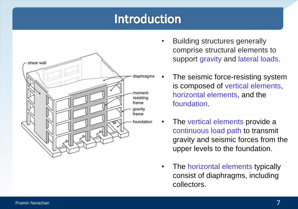
• Building structures generally
comprise structural elements to
support gravity and lateral loads.
• The seismic force-resisting system
is composed of vertical elements,
horizontal elements, and the
foundation.
• The vertical elements provide a
continuous load path to transmit
gravity and seismic forces from the
upper levels to the foundation.
• The horizontal elements typically
consist of diaphragms, including
collectors.

Pramin Norachan 8
• Diaphragms transmit inertial forces
from the floor system to the vertical
elements of the seismic force-resisting
system.
• They also tie the vertical elements
together to stabilize and transmit
forces among these elements as may
be required during earthquake
shaking.
• Diaphragms are thus an essential part
of the seismic force-resisting system
and require design attention by the
structural engineer to ensure the
structural system performs adequately
during earthquake shaking.

Pramin Norachan 9
Diaphragm in-plane forces:
Diaphragms span between, and
transfer forces to, vertical elements
of the lateral-force resisting system.
Diaphragm transfer forces:
Force transfers between vertical
elements which have different
properties over their height, or their
planes of resistance may change
from one story to another.
A common location where planes of
resistance change is at the grade
level of a building with an enlarged
subterranean plan (podium
diaphragm).
Pramin Norachan 10
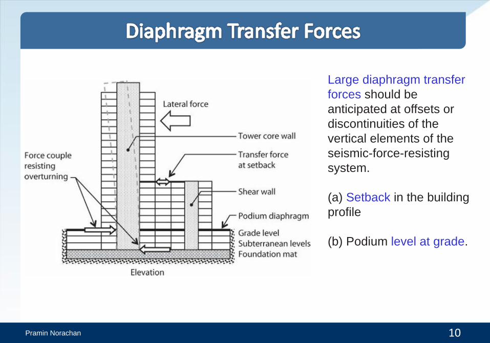
Large diaphragm transfer
forces should be
anticipated at offsets or
discontinuities of the
vertical elements of the
seismic-force-resisting
system.
(a) Setback in the building
profile
(b) Podium level at grade.

Pramin Norachan 11
• In general, low-rise buildings and buildings
with very stiff vertical elements such as
shear walls are more susceptible to floor
diaphragm flexibility problems than taller
structures.

Pramin Norachan 12

Pramin Norachan 13
• Different parts of a diaphragm
include:
- Diaphragm slab
- Chords
- Collectors (Drag struts or
Distributors)
- Connections to the vertical
elements.
• These different parts can be
identified by considering the load
path in a simple diaphragm.
• We can idealize the diaphragm as
a simply supported beam
spanning between two supports,
with reactions and shear and
moment diagrams


Pramin Norachan 16
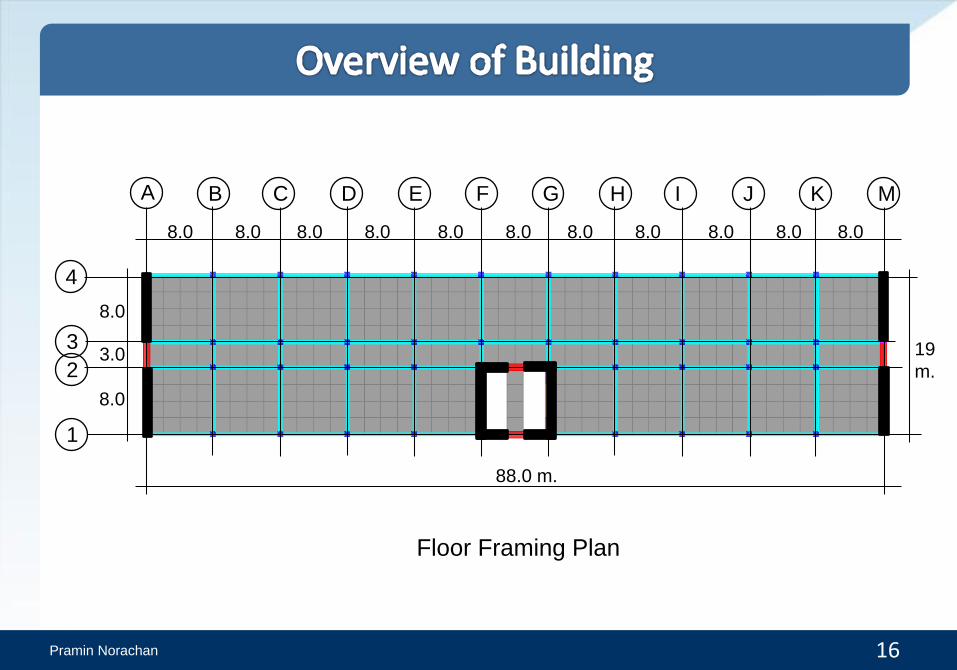
Floor Framing Plan
8.0
B C D E F G H I J K M
4
3
2
1
A
8.0 8.0 8.0 8.0 8.0 8.0 8.0 8.0 8.0 8.0
88.0 m.
8.0
8.0
3.0 19
m.
Pramin Norachan 17
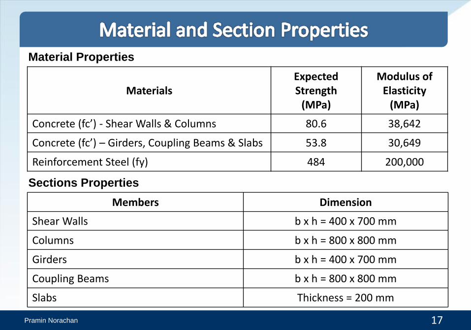
MaterialsExpected Strength
(MPa)
Modulus of Elasticity
(MPa)
Concrete (fc’) - Shear Walls & Columns 80.6 38,642
Concrete (fc’) – Girders, Coupling Beams & Slabs 53.8 30,649
Reinforcement Steel (fy) 484 200,000
Material Properties
Sections Properties
Members Dimension
Shear Walls b x h = 400 x 700 mm
Columns b x h = 800 x 800 mm
Girders b x h = 400 x 700 mm
Coupling Beams b x h = 800 x 800 mm
Slabs Thickness = 200 mm


Pramin Norachan 19
2014 LATBSDC
** Nonlinear fiber elements automatically account for cracking of concrete because the
concrete fibers have zero tension stiffness.
• Stiffness modifiers for RC diaphragms commonly fall in the range of 0.15 to
0.50 when analyzing the building for design-level earthquake demands
(Nakaki, 2000).
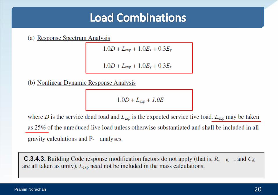
Pramin Norachan 20
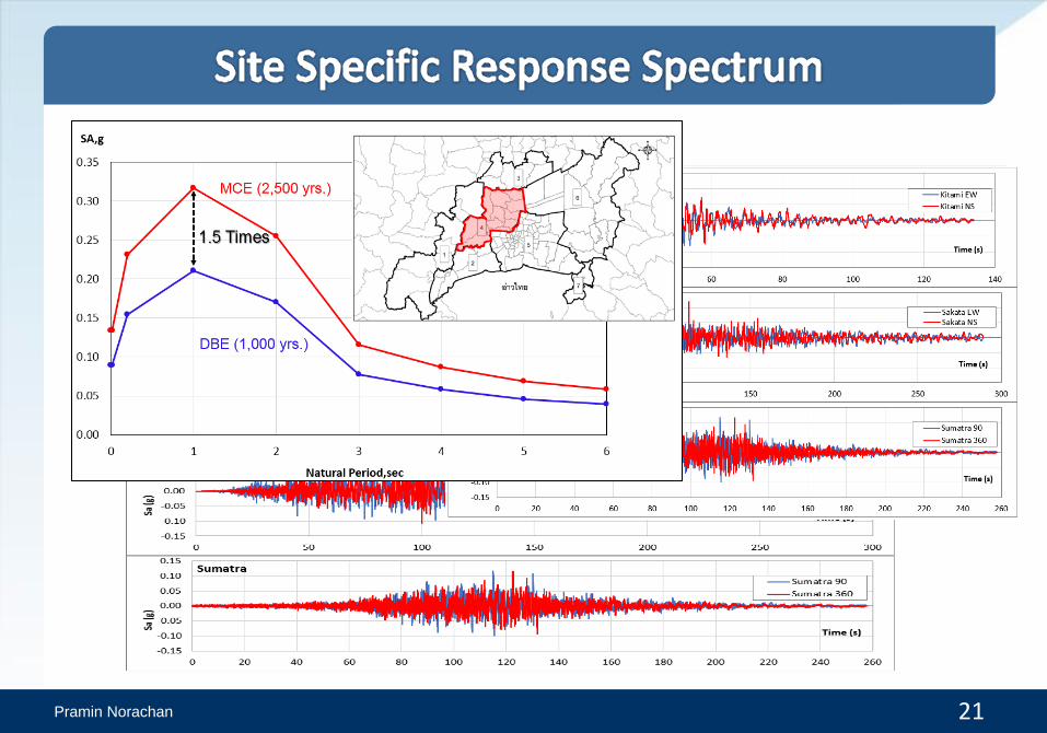
Pramin Norachan 21

Pramin Norachan 22
89,604
71,465 64,639
38,983
0
10,000
20,000
30,000
40,000
50,000
60,000
70,000
80,000
90,000
100,000
H1 H2
Bas
e S
he
ar (
KN
)
Comparison of Base Shear
LRHA NLRHA
Rx = 1.4
Ry = 1.8
( )gu t
xy

Pramin Norachan 23
0
10
20
30
40
50
60
70
80
90
100
0 1 2 3
Elev
atio
n (
m)
Story Acceleration (g)
Office Tower (Story Acceleration in X-dir.)
NLX (g)
MCEX/R (g)

Pramin Norachan 24
PERFORM 3D
(NLTHA) ETABS (RSA)
Before carrying out design checks at MCE, the linear analysis results of
ETABS were scaled to match with the nonlinear time-history analysis results
(NLTHA) from PERFORM-3D.
Pramin Norachan 25
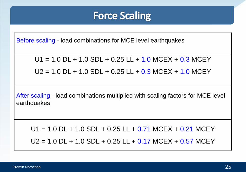
Before scaling - load combinations for MCE level earthquakes
U1 = 1.0 DL + 1.0 SDL + 0.25 LL + 1.0 MCEX + 0.3 MCEY
U2 = 1.0 DL + 1.0 SDL + 0.25 LL + 0.3 MCEX + 1.0 MCEY
After scaling - load combinations multiplied with scaling factors for MCE level
earthquakes
U1 = 1.0 DL + 1.0 SDL + 0.25 LL + 0.71 MCEX + 0.21 MCEY
U2 = 1.0 DL + 1.0 SDL + 0.25 LL + 0.17 MCEX + 0.57 MCEY


Pramin Norachan 27
• Define the response spectrum
function (MCE) that will be used
for analysis.
Pramin Norachan 28
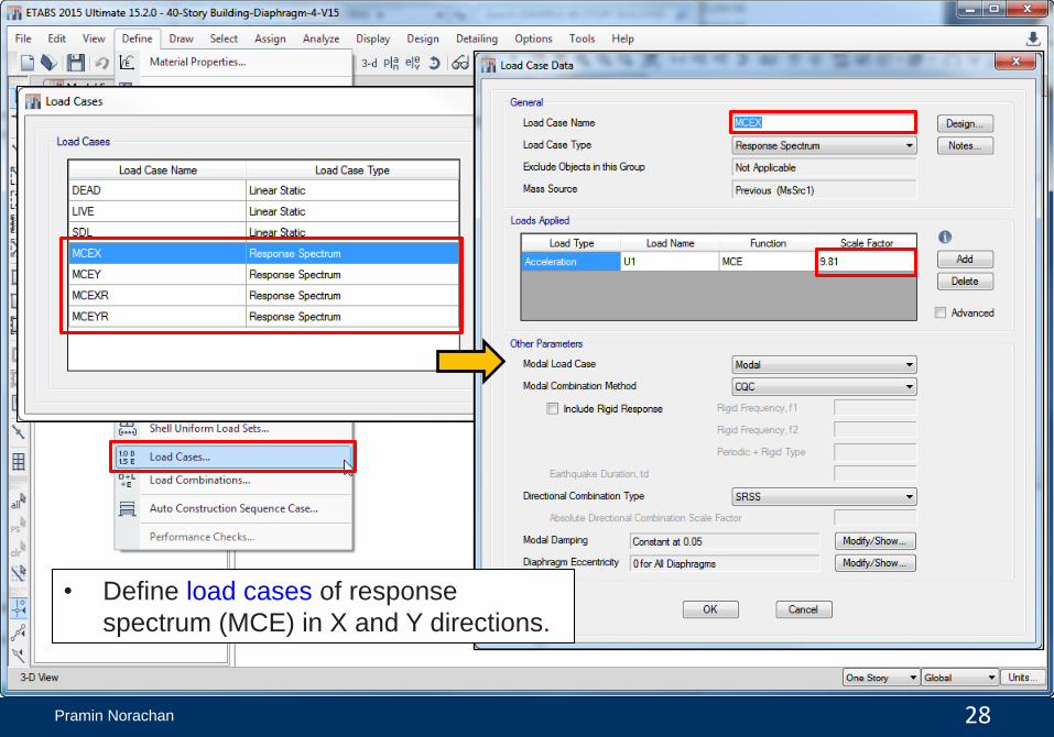
• Define load cases of response
spectrum (MCE) in X and Y directions.

Pramin Norachan 29
• Scale force based on factor
obtained from floor acceleration
or base shear.
9.81/ 2 4.905

Pramin Norachan 30
• Define load combinations for
diaphragm design at MCE level.


Pramin Norachan 32
• Floor diaphragm at Story 20 will
be used as an example for
diaphragm design.

Pramin Norachan 33
• The force resultants in F11 direction on the floor diaphragm at Story 20
are shown below.
F11
F22
F11
SC-1
SC-1
Pramin Norachan 34
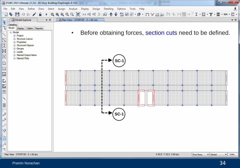
• Before obtaining forces, section cuts need to be defined.
SC-1
SC-1

Pramin Norachan 35
• Select elements and nodes at the cut line.
Then, assign these objects in a group.
SC-1
SC-1

Pramin Norachan 36
• Define the section cut (SC-1) by
selecting the group (SC-1).

Pramin Norachan 37
• However, for this presentation, the section cuts of
this floor diaphragm are already defined as
follows:
Pramin Norachan 38
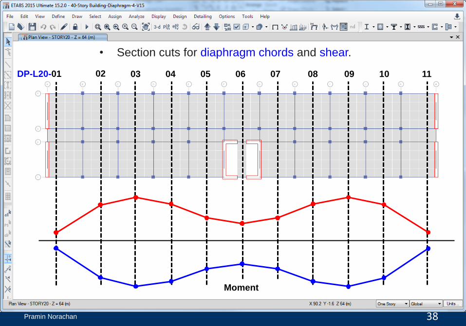
DP-L20-01 02 03 04 05 06 07 08 09 10 11
• Section cuts for diaphragm chords and shear.
Moment
Pramin Norachan 39
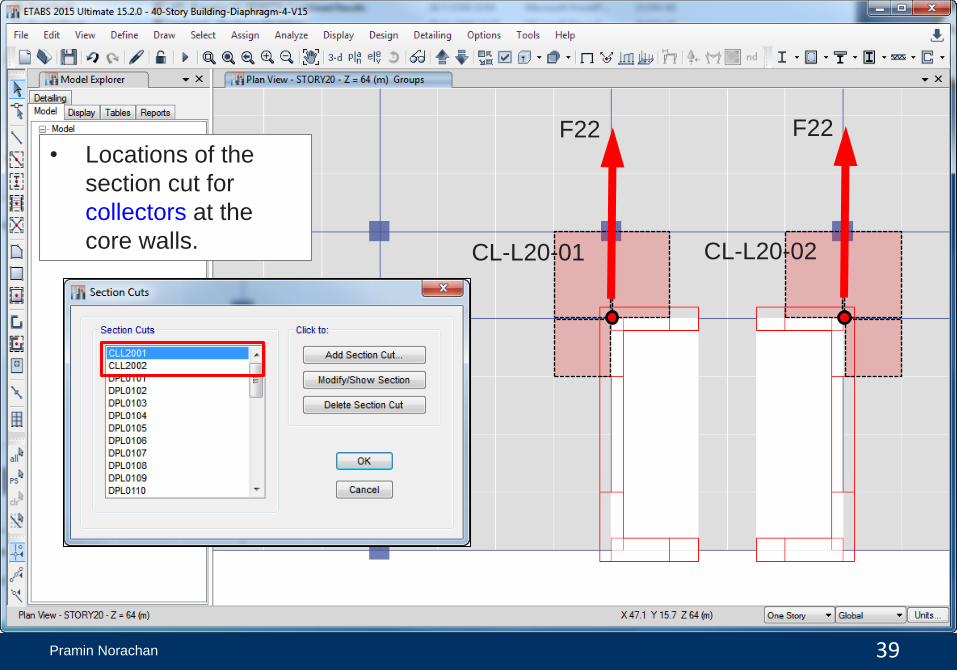
F22 F22
CL-L20-01 CL-L20-02
• Locations of the
section cut for
collectors at the
core walls.

Pramin Norachan 40
• Locations of the section cut for shear friction at
the core walls.
F22 F22
SF-L20-01 SF-L20-02


Pramin Norachan 42
• For a given load case, display any stress of shell force.
F11
F22

Pramin Norachan 43
X
Y

Pramin Norachan 44
• Use the option “Draw Section Cut” to see the force distribution.

Pramin Norachan 45
• Display the results of section cut forces.

Pramin Norachan 46

Pramin Norachan 47
• Select the considered load cases and force directions.
V M

Pramin Norachan 48
V M
• Rearrange all information for design.

Pramin Norachan 49
L01
L20
L39

Pramin Norachan 50
1318
6200 73884624 3415
12719
3487 45447423 6328
1373
-1284
-6295 -7593-5038 -4446
-21749
-4518 -4957-7628 -6423
-1339
-25,000
-20,000
-15,000
-10,000
-5,000
0
5,000
10,000
15,000
0 10 20 30 40 50 60 70 80 90
Mo
me
nt
(KN
-m)
Distance (m)
753
420181
603
932
194
933694
258 292
681
-734
-405-163
-572-865
-194
-1000-725
-276 -307
-700
-1,500
-1,000
-500
0
500
1,000
1,500
0 10 20 30 40 50 60 70 80 90
Sh
ea
r (K
N)
Distance (m)
Story
L01

Pramin Norachan 51
2911
1363416853
15022
104238612
10426
1502016887
13718
3036
-2797
-12924-15627
-13252
-8142-6165
-8145
-13250-15660
-13008
-2923
-20,000
-15,000
-10,000
-5,000
0
5,000
10,000
15,000
20,000
0 10 20 30 40 50 60 70 80 90
Mo
me
nt
(KN
-m)
Distance (m)
1312
691
224
698
1282
177
1486
915
343611
1263
-1369
-753
-292
-771
-1354
-177
-1414
-842
-275-548
-1206
-2,000
-1,500
-1,000
-500
0
500
1,000
1,500
2,000
0 10 20 30 40 50 60 70 80 90
Sh
ea
r (K
N)
Distance (m)
Story
L20

Pramin Norachan
2498
1459818327 17048
12188 10448 1218917059 18366
14672
2604
-2852
-18565
-25412 -27429 -26998 -27242 -26998 -27440 -25452
-18639
-2958
-30,000
-20,000
-10,000
0
10,000
20,000
30,000
0 10 20 30 40 50 60 70 80 90
Mo
me
nt
(KN
-m)
Distance (m)
52
Story
L39
2092
1280
748958
1655
196
1437
715285
726
1569
-1713
-896
-354-571
-1267
-196
-1825
-1103-680
-1110
-1948-2,500
-2,000
-1,500
-1,000
-500
0
500
1,000
1,500
2,000
2,500
0 10 20 30 40 50 60 70 80 90
Sh
ea
r (K
N)
Distance (m)

Pramin Norachan 53
-30,000
-20,000
-10,000
0
10,000
20,000
30,000
0 10 20 30 40 50 60 70 80 90
Mo
me
nt
(KN
-m)
Distance (m) L01 L20 L39
-2,500
-2,000
-1,500
-1,000
-500
0
500
1,000
1,500
2,000
2,500
0 10 20 30 40 50 60 70 80 90
Sh
ea
r (K
N)
Distance (m) L01 L20 L39

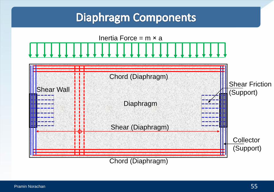
Pramin Norachan 55
Chord (Diaphragm)
Chord (Diaphragm)
Collector
(Support)
Shear Friction
(Support)
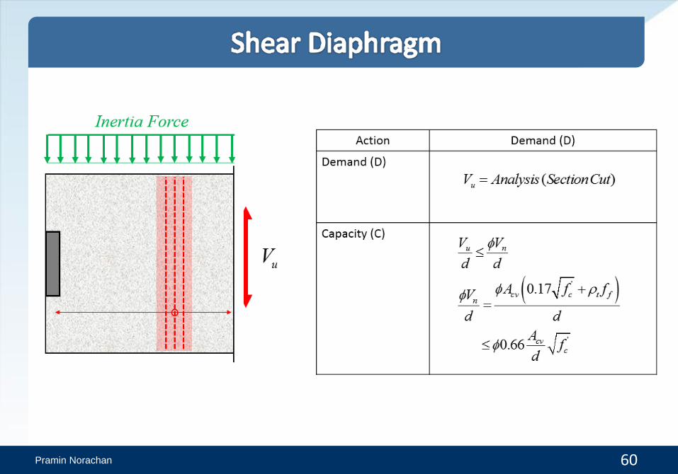
Shear (Diaphragm)
Shear Wall
Diaphragm
Inertia Force = m × a

Pramin Norachan 56
Action Demand (D) Capacity (C)
Force Controlled
(Non-Critical)
Force Controlled
(Critical)
uM M
uT T 1.0
1.0
Tension & Flexure
Compression:
Shear:1.5uV V
1.5uC C
' '1.3c cf f
1.17y yf f
Materials Nominal Strength Expected Strength
Concrete
Reinforcing Steel
'
cf
yf
1.0

Pramin Norachan 57
( )uM Analysis SectionCut
Pramin Norachan 58
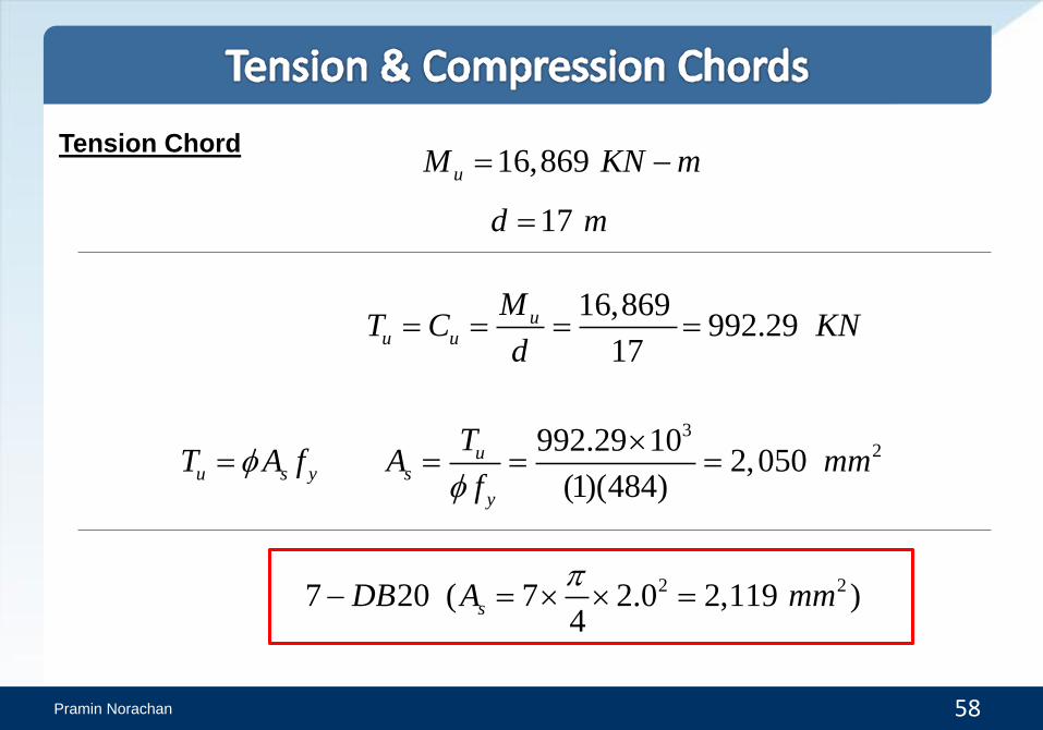
Tension Chord16,869uM KN m
17d m
16,869992.29
17
uu u
MT C KN
d
u s yT A f3
2992.29 102,050
(1)(484)
us
y
TA mm
f
2 27 20 ( 7 2.0 2,119 )4
sDB A mm

Pramin Norachan 59
Compression chord
3992.29 103.54
(400 700)u MPa
Use perimeter beam (400x700 mm)
Allowable stress
'0.5 0.5 53.8 10.76all cf MPa
3.540.34
10.76
u
all
D
C
Pramin Norachan 60

Pramin Norachan 61
Shear 1,485V KN 1.5 1.5 1,485 2,228uV V KN
2,228131 /
17
uVKN m
L
' (200 17,000)0.66 (1.0) 0.66 53.8
(17 1,000)
968.2 /
n,limit cvc
V Af
L L
KN m
' (200 17,000)0.17 (1.0) 0.17 53.8
(17 1,000)
249.4 /
n cvc
V Af
L L
KN m
131 / 249.4 /u nV VKN m KN m
L L
(Okay)
Pramin Norachan 62

Pramin Norachan 63
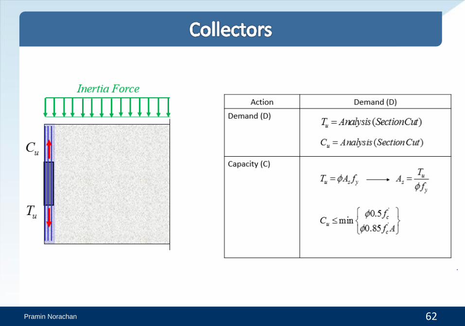
Demand Forces
992
1.5 845 1,268
u
u
T KN
C KN
u s yT A f3
2992 102,050
(1)(484)
us
y
TA mm
f
2 25 25 ( 5 25 2,454 )4
sDB A mm

Pramin Norachan 64
Compression Demand
1.5 845 1,268uC KN
22 2(800)(200)w slabA t t mm
Allowable compression
' (1.0)(0.85)(53.8)(2 200 800)(0.85) 14,634
1,000all cC f A KN
1,2680.09
14,634
u
all
CD
C C
2 wt
wt

Pramin Norachan 65

Pramin Norachan 66
1.5 1,194 1,791uV KN
u n vf yV V A f
1,791 (1.0) (484)(1.0)vfA
21,7913,700
(1.0)(484)(1.0)vfA mm 23,700
0.4625 /8,000
vfAmm mm
L
1 12@ 200DB 2
212 4 1
0.565 /200
sAmm mm
s
Shear Demand

Pramin Norachan 67
' (1.0)(0.2)(53.8)(200 8,000)(0.2) 17,216
1,000min
(1.0)(5.5)(200 8,000)(5.5) 8,800
1,000
8,800
c c
all
c
f A KN
V
A KN
KN
1,791 8,800u allV KN V KN
Allowable shear friction

Pramin Norachan 68
5-DB25 (Collectors)
(2) (6) (7) (6) (2) (4) (2) (6) (7) (6) (2)
(2) (6) (7) (6) (2) (2) (2) (6) (7) (6) (2)
7-DB20 (Chords)
1-DB12@200 (Shear Friction)
7-DB20 (Chords)
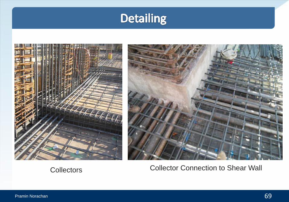
Pramin Norachan 69
Collectors Collector Connection to Shear Wall

Pramin Norachan 70
A long collector with confinement
reinforcement
Shear Friction Rebar
