seismic assessment of a historical masonry … · the collapse mechanisms analysis was ... masonry...
TRANSCRIPT

1
Originally published at the 15th International Conference on Civil, Structural and Environmental Engineering Computing – CIVIL-COMP 2015, Prague, Czech Republic, 2015. Final publication is available in the related proceedings.
SEISMIC ASSESSMENT OF A HISTORICAL MASONRY BUILDING IN SWITZERLAND
Angelo Garofano and Pierino Lestuzzi
École Polytechnique Fédérale de Lausanne (EPFL), EPFL ENAC IIC IMAC e-mail: [email protected]; [email protected]
Abstract This paper presents the results of the investigation on the seismic behaviour of an important historical masonry building, the “Ancien Hôpital de Sion”. The building is sited in the city of Sion, capital of the Canton of Valais, characterized by the highest seismic hazard in Switzerland. The complexity of the structure poses challenging questions in the evaluation of its behaviour, requiring the use of different assessment techniques. A detailed three-dimensional model of the building was developed through the applied element method (AEM), accounting for all possible failure mechanisms occurring in a masonry structure. The analysis of damage distributions allowed to identify the most vulnerable areas of the building and to obtain indications on the necessity of seismic strengthening. The effects of the level of connection offered by the timber floors was also investigated. The kinematic limit analysis was employed for the evaluation of the building’s capacity through possible overturning of the most vulnerable portions of masonry. The collapse mechanisms analysis was performed with both linear and non-linear approaches applying the capacity spectrum method. The numerical and the analytical results were finally compared in order to evidence the applicability of the procedure for the assessment of historical buildings. Keywords: seismic behaviour, historical constructions, timber floors, non-linear dynamic analysis, kinematic limit analysis, applied element method (AEM). 1 Introduction The Ancien Hôpital de Sion is an important and representative Swiss historical masonry building listed in the Federal Inventory of Heritage Sites. The building is located in the city of Sion, capital of the Canton of Valais, the area characterized by

2
the highest seismic hazard in Switzerland. It is, therefore, necessary to assure adequate levels of protection and safety to this cultural heritage symbol.
The paper reports the results of the assessment of the seismic vulnerability of this heritage structure characterised, as it is often in the case of historical constructions, by several challenging aspects, requiring the adoption of different approaches and methodologies in order to correctly describe its actual behaviour [1]. In general, both traditional simplified and recent detailed analysis techniques have been followed providing comparable results at different approximation levels. It is stressed that the different aspects of the particular behaviour of historical buildings can be caught following an integrated procedure in which the results of different method can be opportunely validated [2].
In the present study, a three-dimensional Applied Element (AEM) model of the whole structure was developed for non-linear dynamic analyses. The model is based on a discretization into small masonry elements connected with springs, through which it is possible to represent the non-linear material behaviour, the elements separation and contact [3, 4]. The AEM modelling approach was followed in order to simulate the actual behaviour of the building and to catch the eventual failure mechanisms of such a complex masonry structure.
In addition, the possible local collapse mechanisms of the building were analysed by means of a kinematic limit analysis, which represents a very useful tool for the evaluation of the safety and collapse of structures composed by blocks reaching limit conditions. The vulnerability of the building is studied on the basis of the decomposition into rigid macro-elements, usually identified after the observation of typical seismic failure modes of existing masonry structures [5]. This approach constitutes a useful method particularly in case of buildings which do not present a box behaviour under seismic actions due to poor floors stiffness or connection between walls. In the following, both linear and non-linear approaches are applied and verification are carried out with the capacity spectrum method [6, 7].
2 Information about the structure The Ancien Hôpital de Sion was built on the site of the pre-existing hospital of St-Jean, first mentioned in 1163. The existing building of the Ancien Hôpital was mainly due to the Jesuit father Ignace Schuler. The works were completed in 1781 (Figure 1a) [8, 9].
The building is an isolated masonry structure, as it can be seen from the aerial view reported in Figure 2a, composed by a central body and two external wings (the Aile Nord and the Aile Sud) connected at its extreme sides forming a C-shaped floor plan (see Figure 2b). The building is composed by three levels over the ground floor and in some areas of the structure it also reaches an underground level. The overall floor plan dimensions are 50 m x 42 m; the height of the ground and first level is 3.60 m, while the height of the second level is 3.30 m.

3
(a) (b) Figure 1: Historical pictures of the main façade (a) and the chapel (b) of the Ancien
Hôpital [8]
The structure is roofed with a timber truss structure [10, 11], reaching a total height of 17 m. The central part of the main body of the Ancien Hôpital is occupied by a chapel (see Figure 1b) with a vaulted timber structure, surmounted by a tower with a total height of 26 m. The thickness of the masonry walls varies from about 1 m at the lower level to about 0.8 m at the higher levels.
(a) (b)
Figure 2: Areal view of the building within the city’s historical centre (Source: Map
data ©2015 Google) (a) and floor plan of the ground level [10] (b)
In 2012 visual inspections and hole drillings were performed in the Northern wing with the aim to define the masonry typology, made with irregularly shaped stones, with quite good arrangement. The state of conservation of mortar joints was also good (Figure 3a).
The slabs found in the structure are made with timber beams (approximatively squared cross-section), with a timber layer, a mortar layer and the pavement. An example is shown in Figure 3b. Some slabs have been object of ultrasonic in-situ testing for characterization of materials in 2012 [12, 13]. Three classes were identified (C18, C24 and C30, according to the European Norm EN338 [14]). The beams were mainly belonging to the class of strength C30, while some C24 class

4
beams were also found in the Southern wing and few C18 class in the Northern wing. The surveyed beams presented squared cross-sections of about 20 cm x 20 cm, with interspacing of 45-50 cm and supported length of about 30 cm.
(a) (b) Figure 3: Masonry typology found in the building (a) and bottom view of the slab’s
structure (b) [12]
3 Seismic input for the dynamic analysis A specific microzonation study is available for the site of the Ancien Hôpital [15], described by the response spectrum represented as a dashed line in Figure 4b. For the non-linear dynamic analysis of the building some records of seismic events respectful of the best fitting with the response spectrum were selected; one of these is reported in Figure 4a. The recorded ground motion is characterized by a PGA of 0.224 g. The corresponding elastic response spectra in the X (N-S) and Y (E-W) directions for 5% damping are illustrated in Figure 4b.
0.0
1.0
2.0
3.0
4.0
5.0
6.0
7.0
0.00 0.05 0.10 0.15 0.20 0.25
S a[m
/s2 ]
Sd [m]
Component XComponent Y
(a) (b)
Figure 4: Record ESD 198 (European Strong Motion Database, Montenegro Earthquake, MS = 7.1, PGA = 0.224g): recorded ground accelerations in X and Y
directions (a) and elastic response spectra (ADRS format) for 5% damping (b)
-2.5
-1.5
-0.5
0.5
1.5
2.5
0 5 10 15 20 25 30 35 40
Acc
eler
atio
n [m
/s2 ]
Time [s]
Component XComponent Y

5
4 Numerical model of the building 4.1 Applied Element strategy and material model for masonry The numerical model of the building was carried out following the Applied Element Method (AEM), which represents an alternative technique compared to the Finite Element Method. The advantages offered by the AEM are mainly associated to the capability to describe all the possible failure mechanisms occurring in a masonry building from one side, and to describe elements separations and large displacement during a non-linear dynamic analysis from the other [4, 13, 14]. Therefore, the model is divided in small elements connected through normal and shear springs, without creating common nodes. The use of springs allows to easily describe large displacements and elements progressive separation through successive failure of these springs [3].
For the studied masonry building, a total number of five springs was used on each face of the elements. The size of the meshing was selected to avoid creating elements with large aspect ratios and was opportunely validated [19]. The model of the building is reported in Figure 5a, where the timber beams of the floors can be seen. The other layers composing the floors are also included in the model but not in the view. Two different element sizes for the masonry walls were considered in order to analyse the effect in the results: a refined mesh (element dimensions ≤ 0.4 m) with two elements in the wall thickness and a large mesh division (element dimensions ≤ 0.8 m), with only one element in the wall thickness.
(a) (b)
Figure 5: Three-dimensional model of the building with the view of timber beams
(a) and constitutive models for masonry in tension/compression and shear (b)
The material’s characteristics are described through the springs’ properties, as reported in Table 1, used to calculate strains, stresses and failure criteria [15]. Masonry is modelled similarly to concrete, adopting the Maekawa compression model including unloading and reloading [20], shown in Figure 5b. The material is

6
assumed to crack when the major principal stress reaches the tensile strength. After cracking, stiffness of springs subjected to tension is set to zero. The relationship between shear stress and shear strain is assumed to remain linear till the cracking. Then, the shear stresses drop down as shown in Figure 5b. The level of drop of shear stresses depends on the aggregate interlock and friction at the crack surface. When the separation strain is reached, the adjacent elements are totally separated at the connecting face. In this case, all the springs are cut and, if the elements meet again during the analysis, they behave as two different rigid bodies in contact.
Unit
weight Young's modulus
Shear modulus
Tensile strength
Compressive strength
Separation strain
Friction coefficient
[kN/m3] [N/mm2] [N/mm2] [N/mm2] [N/mm2] [−] [−] 21 1500 700 0.25 3 0.1 0.8
External damping ratio
Normal contact stiffness factor
Shear contact stiffness factor
Contact spring unloading stiffness factor
[−] [−] [−] [−] 0 1·10-4 1·10-5 2
Table 1: Mechanical parameters for masonry
4.2 Synthesis of the results of the numerical analyses 4.2.1 Modal analyses The first two modes of the building involve the vibration of the central tower in the two principal directions (see Figure 6a and 6b), also representing the most vulnerable part of the structure. The higher modes involve the lateral wings of the building. The modal shapes are the same in the case of the refined and large mesh division. The values of the periods for the first three modes are reported in Table 2. The differences when considering the refined mesh are negligible (lower than 3% for the first three modes) compared to the case of large mesh, confirming the reliability of the model with large mesh from the dynamical point of view.
(a) 1st Mode (b) 2nd Mode (c) 3rd Mode
Figure 6: Modal shapes of the building associated to the first three vibration modes

7
Mode Refined mesh Large mesh Δ [%] T [s] T [s] 1 0.222 0.219 +1.4 2 0.215 0.218 +1.5 3 0.175 0.170 +2.7
Table 2: Increments of the first three vibration periods obtained in the case of
refined mesh compared to the case of the large mesh 4.2.2 Non-linear dynamic analyses A non-linear dynamic analysis was firstly carried out considering the recorded time-history reported in Figure 4. The analysis confirmed that the most vulnerable part of the structure is the central tower, which presented out-of-plane damages, while the rest of the building did not suffer high damages when subjected to this seismic registration. The most evident crack is located in the middle of the back wall of the Southern wing.
In a second phase, a non-linear analysis was performed in order to evaluate a level of ground acceleration corresponding to higher damage conditions. The record considered in the first case was therefore amplified through the application of a factor of 2 to the acceleration ordinates, therefore obtaining a double value of PGA. The damage distribution obtained in this second case is reported in Figure 7a, where the formation of several cracks and the overturning of portions of masonry can be noticed. The Southern wing suffered higher damage, with the connection between converging walls often lost. Severe damage was also obtained at the back of the central body of the buildings, involving the walls enclosing the staircases. In the Northern wing, instead, cracking was more distributed and mainly starting from the openings.
(a) (b) Figure 7: Damage distribution at the last time step (t = 40 s) in the case with (a) and
without (b) timber slabs
8
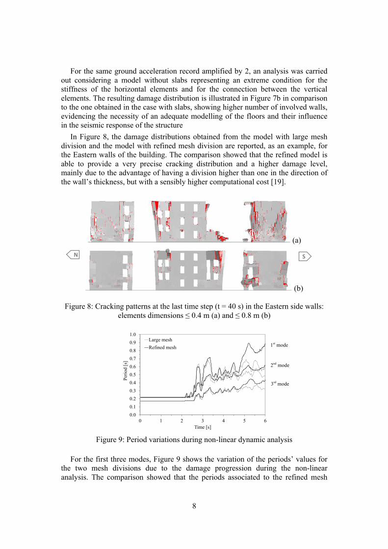
For the same ground acceleration record amplified by 2, an analysis was carried out considering a model without slabs representing an extreme condition for the stiffness of the horizontal elements and for the connection between the vertical elements. The resulting damage distribution is illustrated in Figure 7b in comparison to the one obtained in the case with slabs, showing higher number of involved walls, evidencing the necessity of an adequate modelling of the floors and their influence in the seismic response of the structure
In Figure 8, the damage distributions obtained from the model with large mesh division and the model with refined mesh division are reported, as an example, for the Eastern walls of the building. The comparison showed that the refined model is able to provide a very precise cracking distribution and a higher damage level, mainly due to the advantage of having a division higher than one in the direction of the wall’s thickness, but with a sensibly higher computational cost [19].
(a)
(b)
Figure 8: Cracking patterns at the last time step (t = 40 s) in the Eastern side walls: elements dimensions ≤ 0.4 m (a) and ≤ 0.8 m (b)
0.00.10.20.30.40.50.60.70.80.91.0
0 1 2 3 4 5 6
Perio
d [s
]
Time [s]
Large meshRefined mesh
Figure 9: Period variations during non-linear dynamic analysis
For the first three modes, Figure 9 shows the variation of the periods’ values for the two mesh divisions due to the damage progression during the non-linear analysis. The comparison showed that the periods associated to the refined mesh
1st mode
2nd mode
3rd mode
N S

9
reduce more than in the case of the normal mesh for the higher time steps. Therefore, it was found that the model with refined mesh is more susceptible to present higher damage. 5 Kinematic limit analysis of local collapse mechanisms 5.1 Linear and non-linear approaches Masonry buildings are subjected to partial collapses during earthquakes, generally due to loss of equilibrium of masonry portions. Local mechanisms may involve single masonry panels or wider portions of the building and they are fostered by the poor or absent level of connection between the structural elements of the building, i.e. vertical walls and slabs. The verification of the safety with regards to such mechanisms can be carried out if the masonry portion can be assumed to behave monolithically, and specifically if local disaggregation of masonry is avoided. The verification of the local collapse mechanisms can be carried out by means of the limit equilibrium analysis according to a kinematic approach [5, 21, 22].
The kinematic linear approach allows to define the value of the load multiplier, α0, connected to the horizontal force that the element is able to withstand, by applying the P.V.W. in terms of displacements (by equating the total work of the external and internal forces). The seismic spectral acceleration, a*0, can be obtained multiplying the horizontal load multiplier, α0, by the acceleration of gravity, g, and dividing by the fraction of mass participating to the mechanism, e*. In terms of acceleration, the safety of the structure against the considered collapse mechanism is satisfied if:
a*0 ≥ ag(SLU) (1) where ag(SLU) is the acceleration demand imposed by the earthquake calculated assuming a strength reduction factor equal to 2 [23].
The displacement capacity of the element according to the considered collapse mechanisms can be described though its capacity curve, obtained by means of the kinematic non-linear analysis. On the basis of the capacity curve describing to the considered collapse mechanism it is possible to define the spectral capacity curve (a* – d*) associated to the equivalent single d.o.f. system corresponding to the macro-element.
The safety of the structure against the considered local mechanism is carried out through the comparison between the ultimate displacement capacity, represented by d*u (assumed as 40% of the spectral displacement, d*0, corresponding to a null value of a* [23]), and the displacement demand, Δd = SDe(Ts), obtained from the displacement spectrum for the secant period, Ts. The safety is satisfied if: d*u ≥ Δd (2)

10
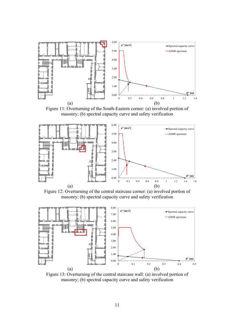
5.2 Verification of the mechanisms The local collapse mechanisms analysed for the structure of the Ancien Hôpital concern the overturning of the whole Southern façade of the building (Figure 10a), the South-Eastern corner (Figure 11a), the Southern corner of the building (Figure 12a) and the central staircase wall (Figure 13a).
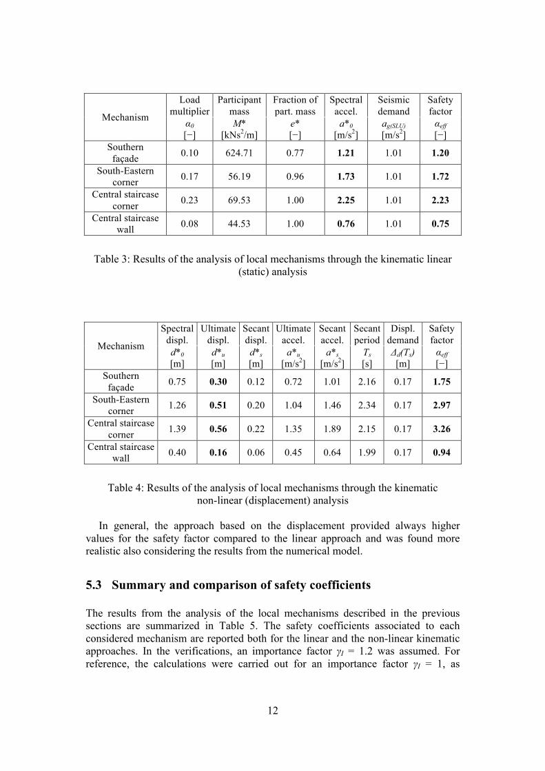
The verification of the safety with respect to the different mechanisms was firstly carried out according to the kinematic linear approach. The results of the analysis are summarized in Table 3, where the horizontal load multiplied, α0, associated to each of the considered mechanisms are reported. In the table the spectral acceleration responsible for the activation of the mechanisms, a*0, associated to the equivalent single d.o.f. system is compared with the seismic demand in terms of acceleration, ag(SLU). The obtained safety factors, αeff, are higher than one apart from the case of the central staircase wall. It is specified that the calculation are carried out considering an importance factor, γI = 1.2, for the studied building.
The verification of the mechanism has been carried out considering also the displacement capacity of the masonry macro-element through the kinematic non-linear approach. Also in this case, the importance factor, γI = 1.2, was taken into account. The graphs reported in the Figures 10b–13b show the graphical comparison between seismic demand/capacity. The spectral capacity curve (a* – d*) of the overturning macro-element is compared to the seismic spectrum at the building’s site in ADSR format. In the graphs, the points corresponding to the ultimate spectral displacement d*u associated to the equivalent single d.o.f. system and the displacement demand Δd are indicated for a direct comparison. The red dots correspond to the displacement capacity and the performance points are all situated in the constant displacement branch of the response spectrum. In Table 4, the results of the verification for each of the considered mechanisms are summarized. As in the case of the linear approach, the safety factor is lower than one only in the case of the central staircase wall.
0.00
1.00
2.00
3.00
4.00
5.00
6.00
0 0.1 0.2 0.3 0.4 0.5 0.6 0.7 0.8
a* [m/s2]
d* [m]
Spectral capacity curveADSR spectrum
(a) (b) Figure 10: Overturning of the Southern façade: (a) involved portion of masonry; (b)
spectral capacity curve and safety verification
11
0.00
1.00
2.00
3.00
4.00
5.00
6.00
0 0.2 0.4 0.6 0.8 1 1.2 1.4
a* [m/s2]
d* [m]
Spectral capacity curve
ADSR spectrum
(a) (b)
Figure 11: Overturning of the South-Eastern corner: (a) involved portion of masonry; (b) spectral capacity curve and safety verification
0.00
1.00
2.00
3.00
4.00
5.00
6.00
0 0.2 0.4 0.6 0.8 1 1.2 1.4 1.6
a* [m/s2]
d* [m]
Spectral capacity curve
ADSR spectrum
(a) (b)
Figure 12: Overturning of the central staircase corner: (a) involved portion of masonry; (b) spectral capacity curve and safety verification
0.00
1.00
2.00
3.00
4.00
5.00
6.00
7.00
8.00
0 0.1 0.2 0.3 0.4 0.5
a* [m/s2]
d* [m]
Spectral capacity curve
ADSR spectrum
(a) (b)
Figure 13: Overturning of the central staircase wall: (a) involved portion of masonry; (b) spectral capacity curve and safety verification
12
Mechanism
Load multiplier
Participant mass
Fraction of part. mass
Spectral accel.
Seismic demand
Safety factor
α0 [−]
M* [kNs2/m]
e* [−]
a*0 [m/s2]
ag(SLU) [m/s2]
αeff [−]
Southern façade 0.10 624.71 0.77 1.21 1.01 1.20
South-Eastern corner 0.17 56.19 0.96 1.73 1.01 1.72
Central staircase corner 0.23 69.53 1.00 2.25 1.01 2.23
Central staircase wall 0.08 44.53 1.00 0.76 1.01 0.75
Table 3: Results of the analysis of local mechanisms through the kinematic linear
(static) analysis
Mechanism
Spectral displ.
Ultimate displ.
Secant displ.
Ultimate accel.
Secant accel.
Secant period
Displ. demand
Safety factor
d*0 [m]
d*u [m]
d*s [m]
a*u [m/s2]
a*s [m/s2]
Ts [s]
Δd(Ts) [m]
αeff [−]
Southern façade 0.75 0.30 0.12 0.72 1.01 2.16 0.17 1.75
South-Eastern corner 1.26 0.51 0.20 1.04 1.46 2.34 0.17 2.97
Central staircase corner 1.39 0.56 0.22 1.35 1.89 2.15 0.17 3.26
Central staircase wall 0.40 0.16 0.06 0.45 0.64 1.99 0.17 0.94
Table 4: Results of the analysis of local mechanisms through the kinematic
non-linear (displacement) analysis
In general, the approach based on the displacement provided always higher values for the safety factor compared to the linear approach and was found more realistic also considering the results from the numerical model.
5.3 Summary and comparison of safety coefficients The results from the analysis of the local mechanisms described in the previous sections are summarized in Table 5. The safety coefficients associated to each considered mechanism are reported both for the linear and the non-linear kinematic approaches. In the verifications, an importance factor γI = 1.2 was assumed. For reference, the calculations were carried out for an importance factor γI = 1, as

13
reported in the same table. For all the considered mechanisms, the safety factors provided by the linear analysis are lower than the safety factors obtained through the non-linear analysis.
Mechanism
Importance factor γI = 1.2 Importance factor γI = 1 αeff [−] αeff [−]
Linear analysis
Non-linear analysis
Linear analysis
Non-linear analysis
Southern façade 1.20 1.75 1.44 2.10
South-Eastern corner 1.72 2.97 2.06 3.56
Central staircase corner 2.23 3.26 2.68 3.92
Central staircase wall 0.75 0.94 0.90 1.13
Table 5: Summary of safety factors from the analysis of local mechanisms
The safety factors are generally higher than one, except for the case of the central
staircase wall at the back of the building where values lower than one or slightly higher (1.13 in case of non-linear analysis with γI = 1) were found.
Considering γI = 1, for the local mechanism involving the South-Eastern corner safety factor of about 2 was obtained from the linear analysis, and more than 3 from the non-linear analysis. Considering the results from the model, the analysis with the accelerogram amplified by 2 produced some cracking passing along the opening at this corner, though without causing the overturning of this portion of masonry.
For the mechanism associated to the masonry corner at the central staircase location, safety factors higher than 2 where obtained (2.68 and 3.92 for the linear and non-linear approaches respectively, considering γI = 1). The results from the numerical modelling showed that this area of the building suffer major damaging for the seismic registration amplified by 2, causing the collapse of the walls converging in the corner around the staircase. However, the walls forming the corner seemed to separate from the rest of the building during the application of the acceleration time history. A vertical crack also forms between the walls connected in the corner before the overturning of the whole portion of masonry. The safety coefficients associated to a single wall are 0.9 from the linear approach and 1.13 from the non-linear approach, indicating the possible overturning of the wall for an action slightly higher than 1 (non-amplified registration). In this case, considering the results from the model run with a seismic registration amplified by 2, the results from the analysis of the local mechanism seem to be too conservative.
14
6 Conclusions The study of the seismic safety of the Ancien Hôpital de Sion was carried out through different assessment methods. The results of the non-linear dynamic analyses performed on the AEM model and the study of the main local collapse mechanisms led to the identification of the most vulnerable parts of the structure. The building, initially subjected to a recorded acceleration time history close to the response spectrum at the site, was able to stand quite well the seismic action suffering minor cracking, with the exception of the central tower. This part of the structure turned out to be quite vulnerable and will be the object of deeper investigations in the next future.
Due to its historical value, the safety of this structure was studied also considering seismic actions with higher return period. Therefore, the building was subjected to an acceleration time history amplified by a factor of two. A more significant damage was observed in the area of the Southern wing and in the walls enclosing the staircases, where wall’s separation occurred at the corners.
The safety factors provided by the collapse mechanisms analysis are higher than one except for the case of the central staircase wall at the back of the building. In comparison, the model subjected to the non-amplified seismic registration, showed a diffuse cracking in the area of this wall, but without reaching its out-of-plane failure. Therefore, in this case the application of the mechanisms analysis is more conservative, particularly in the linear approach.
For the Southern façade and the South-Eastern corner, the results of the numerical analyses are intermediate between the results given by the linear and the non-linear approaches. The model showed severe cracking and disconnection of masonry at the corners, but without complete overturning of the walls. Therefore, also in this case the application of the linear approach resulted to be more conservative than the non-linear approach, which was found more realistic.
Acknowledgements
The present research was conducted with the support of the Office Fédéral de l’Environnement (OFEV) which is fully acknowledged.
References [1] F. Ceroni, M. Pecce, S. Sica, A. Garofano, “Assessment of seismic
vulnerability of a historical masonry building”, Buildings, MDPI, Special Issue: Earthquake Resistant Buildings, 2012; 2(3):332-358. DOI: 10.3390/buildings2030332.
[2] F. Ceroni, A. Garofano, M. Pecce, “Seismic behaviour of masonry buildings: application of different approaches to a case study”, 14th European Conference of Earthquake Engineering, 30.08-03.09.2010 Ohrid, Macedonia, CD Rom.

15
[3] K. Meguro, H.R. Tagel-Din, “Applied element simulation of RC structures under cyclic loading”, Journal of Structural Engineering, Vol. 127, No. 11, November, 2001.
[4] H.R. Tagel-Din, K. Meguro, “Analysis of a small scale RC building subjected to shaking table tests using applied element method”, Proceedings of the 12th World Conference on Earthquake Engineering, New Zealand, pp. 25–34, January 30 – February, 2000.
[5] C.F. Carocci, “Guidelines for the safety and preservation of historical centres in seismic areas”, In: Historical constructions. University of Minho, Guimaraes, pp 145–165, 2001.
[6] P. Fajfar, “Capacity spectrum method based on inelastic demand spectra”, Earthquake Engineering and Structural Dynamics, 28:979–993, 1999.
[7] S. Lagomarsino, “On the vulnerability assessment of monumental buildings”, Bulletin of Earthquake Engineering, 4:445–463. European Comission, Brussels, 2006.
[8] S. Crettaz, “Hôpital de Sion (XIIe au XXe siècle)”, In: Annales Valaisannes, Société d'Histoire du Valais Romand, 1949, 145-180, fig. (dont 1 portr.). (In French).
[9] P. de Rivaz, “Les hôpitaux de Sion. In: Annales Valaisannes”, Société d'Histoire du Valais Romand, 1940, 44-48. (In French).
[10] CERT Ingénierie SA, “Ville de Sion. Rénovation de l'Ancien Hôpital. Étude de faisabilité: toiture, plancher et colombage”, 20 Novembre 2009. (In French)
[11] Lignum-Cedotec, “Rapport "Ancien Hôpital de Sion" - Charpente et planchers en bois. 2 June 2009. (In French).
[12] CERT Ingénierie SA, “Ville de Sion. Rénovation de l'Ancien Hôpital. Rapport d’évaluation de la capacité portante des planchers en bois”, Rapport AVP101, 5 June 2012. (In French).
[13] Concept Bois Technologie, “Evaluation de la résistance résiduelle de poutres en bois constituant le plancher de l’Ancien Hôpital de Sion (VS). Mesures sur échantillonnage”, Rapport d'expertise, 12 May 2012. (In French).
[14] European Commitee for Standardization (CEN), “EN 338 - Structural timber. Strength classes”, 2009.
[15] Centre de recherche sur l’environnement alpin (CREALP), “Seismic microzonation map for the city of Sion”, www.crealp.ch.
[16] A. Karbassi, P. Lestuzzi, “Fragility analysis of existing unreinforced masonry buildings through a numerical-based methodology”, The Open Civil Engineering Journal, vol. 6, (Suppl. 1-M2) 121-130, 2012.
[17] A. Karbassi, M.-J. Nollet, “Performance based seismic vulnerability evaluation of masonry buildings using Applied Element Method in a nonlinear dynamic-based analytical procedure”, Earthquake Spectra, Vol. 29, No. 2, 399-426, 2013.
[18] Applied Science International. “Extreme Loading® for Structures (Version 3.1), Theoretical Manual; Modelling Manual”, Durham, NC, 2013.
[19] A. Garofano, P. Lestuzzi, “Evaluation of the vulnerability of the “Ancien Hôpital de Sion” using Applied Element Modelling (AEM) and local mechanisms analysis”, 5th International Conference on Computational

16
Methods in Structural Dynamics and Earthquake Engineering – COMPDYN 2015 (ECCOMAS Thematic Conference), 25-27 May 2015, Crete Island, Greece.
[20] H. Okamura, K. Maekawa, “Nonlinear analysis constitutive models of reinforced concrete”, Gihodo Co. Ltd., Tokyo, 1991.
[21] F. Papa, G. Zuccaro, “Un modello di valutazione dell’agibilità post-sismica attraverso la stima dei meccanismi di collasso”, XI Congresso Nazionale ANIDIS “L’Ingegneria Sismica in Italia”, Genova, 2004.
[22] M.C. Griffith, G. Magenes, G. Melis, L. Picchi, “Evaluation of out-of-plane stability of unreinforced masonry walls subjected to seismic excitation”, Journal of Earthquake Engineering, Vol. 7, Special Issue 1, 141-169, 2003.
[23] Circolare 617, “Istruzioni per l’applicazione delle “Nuove norme tecniche per le costruzioni” di cui al D.M. 14 gennaio 2008”, Ministero dei Lavori Pubblici, Roma, 02/02/2009. (In Italian).