seismic assessment and strengthening of an · pdf fileseismic assessment and strengthening of...
TRANSCRIPT
1
SEISMIC ASSESSMENT AND STRENGTHENING OF AN EXISTING
MULTI-STOREY MASONRY BUILDING IN SARAJEVO, BOSNIA AND
HERZEGOVINA
Naida ADEMOVIĆ1 and Mustafa HRASNICA
2
ABSTRACT
The paper discussed the behaviour of a typical multi-storey masonry residential building in Sarajevo
as part of the massive construction during the 50's and 60's in the Western Balkans. It is noted that
these kinds of buildings have been designed without utilizing any seismic codes. Structural walls are
located mainly in one direction. As, such buildings represent a large portion of residential unreinforced
masonry building stock in a wider region, which most probably do not satisfy the latest code
provisions, this leads to the necessity for investigation of their seismic vulnerability. Global numerical
models of the building taking into account nonlinear material characteristics have been created. Time
History Analysis was done in Finite Element Method (FEM) program, while Pushover Analysis was
done in Equivalent Frame Model (EFM) as well. Several comparisons were done and results were
found to be in a very good correlation. The paper's aim was to assess the seismic safety of this type of
structure. As the building showed inadequate behaviour in X-direction strengthening proposals have
been made.
1. INTRODUCTION
Seismic activity in Bosnia and Herzegovina (B&H) is connected to the existence of deep lateral and
reverse faults. The fact that the second biggest belt (Alpine Belt), going from the Himalayas over Iran,
Turkey and Greece, passes through B&H verifies the tectonic activity of this region (Ademović et al.,
2013). As per Euro Mediterranean Seismic Hazard Map, B&H falls in the Moderate Seismic Hazard
having the PGA in the range of 0.08 to 0.24g, while a south-west part of the country experiences a
High Hazard (PGA>0.24g). According to the seismological data, annually 1100 earthquakes of
intensity lower than III by Mercalli-Cancani-Sieberg (MCS) were registered, while in the last 104
years 1084 earthquakes of the Richter's magnitude greater than 3 were registered as well.
Effects of the devastating earthquakes that struck this region are illustrated in Fig.1(a) and Fig. 1
(b).
1 Assistant Professor, Faculty of Civil Engineering University of Sarajevo, Sarajevo, [email protected]
2 Professor, Faculty of Civil Engineering University of Sarajevo, Sarajevo, [email protected]

2
Figure 1. (a) Banja Luka 1969 earthquake and (b) Skopje earthquake (Petrovski, 2003)
The building presented in this paper, as illustrated in Fig. 2(a), is of the same type as the one
shown in Fig.1(b). It is noted that these kinds of building have been designed without utilizing any
seismic codes (these codes did not exist in this region at that time). As a consequence generally they
do not satisfy modern technical standards. It is of the utmost importance to investigate their seismic
vulnerability and propose possible methods of strengthening, if required.
These types of masonry buildings were constructed with bricks produced in factory, but without
vertical confining elements. These building are defined as unreinforced masonry (URM) without
confinement. Older buildings have usually wooden floors, while buildings built after World War II
generally have R.C. floors. The first belong mostly to vulnerability class B where very heavy damages
can be expected for the earthquakes whose intensity corresponds to the seismic zone 8. Masonry
buildings with R.C. floors according to EMS classification could stand heavy damages of the structure
including falling down of some walls for the intensity degree 9 and they belong mostly to vulnerability
class C (Hrasnica, 2009).
The vulnerability of this building lies in its height, having structural walls mostly in only one
direction, no vertical R.C. confining elements. According to EMS-98 it belongs to the unconfined
masonry, younger than approx. 60 years with reinforced concrete floors and for the 7th degree of
seismic intensity moderate to heavy damages (grade 3-4) could be expected.
Analysis of existing buildings is usually more challenging compared with designing of new
structures. The biggest problem is the collection of reliable data regarding the structural capacity of the
existing building. Usually the design documentation is missing, and it is very rare to find site
documentation that could attest the quality of materials and its compliance with approved construction
project. Recently, in the framework of modern technical regulations specific parts deal with the
existing building, aiming to introduce uniform procedures, which are common in the design of new
buildings. A methodology for the assessment of this existing masonry multi-storey structure according
to the ICOMOS-Recommendations for the Analysis, Conservation and Structural Restoration of
Architectural Heritage was used as shown in Fig. 2(b).
Figure 2. (a) Analyzed building, built in 1957 (b) Methodology by ICOMOS

N.Ademović and M.Hrasnica 3
2. ANALYSED STRUCTURE
As per Figure 2(b), first step is gathering historical information about the structure. These buildings
are mainly located in urban regions of the cities as isolated buildings or several of them are attached
together making a block of buildings. Original design was obtained from the authorities. The building
has 7 levels (basement + ground floor + 5 storeys) and the basement is underneath the entire structure.
There were no structural changes on the building as to the original design. Verification of the
geometric data was done with laser distancemeters and total stations, on the basis of which drawings
of the existing building were performed. As seen from the original static calculations no seismic
regulations were applied, and no structural analysis was done in this manner. The structure was built
without vertical confinement and structural walls are located mainly in one direction (Y direction).
The visual inspection included three phases, the geometry survey, the material survey, and the damage
survey.
2.1. Geometry survey and visual inspection
In the plan, the structure is of dimensions 38.0m by 13.0m with 7 levels. It has been built in 1957 and
it did not undergo any structural changes. Structural walls are mainly in the transverse direction (Y
direction, see also Fig. 3). A significant percentage of openings in the amount of 46% of the wall area
is in the longitudinal walls (Ademović, 2012). Accordingly, the lateral resistance in X direction is
significantly inferior to the lateral resistance in the transverse (Y) direction. Only two inner walls in X
direction are without openings. The external structural walls are made of standard brick elements
25x12x6.5cm and non-structural façade made of hollow bricks 0.125m thick, while the inner structural
walls are 0.25m thick solid brick walls, all connected with cement-hydraulic mortar (Fig.3). The slabs
are made out of semi-prefabricated concrete slabs "Herbst" with concrete hollow elements, details can
be found in (Ademović, 2011). Basement walls are made out of reinforced concrete. Inner walls of the
basement in Y direction are 0.38m thick, while the outer walls in X direction are 0.30m thick, and two
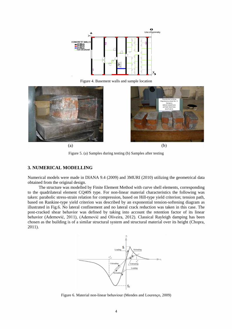
inner walls are 0.25m thick, as shown in Fig.4. No damages were observed on the structure.
2.2 Laboratory tests
Brick units and concrete cylinders were taken out from representative locations in the structure as
illustrated in Fig.3 and Fig.4. Samples of brick during testing of compressive strength are shown in
Fig.5(a), while Fig.5(b) shows brick samples after testing procedure. Testing was done at the Institute
for Materials and Structures of the Faculty of Civil Engineering in Sarajevo (IMK, 2010).
Compressive strength of bricks was determined according to the Bosnian standards. It was
determined that the compressive strength of bricks corresponds to the class M150 (new M15) and
fulfills the requirement for structural walls. Experimentally it was determined that the basement walls
are made out of reinforced concrete, corresponding to grade C20/25, and a reinforcement ø=14mm,
type of steel GA240/360 (fy=240 MPa).
Figure 3. Masonry walls and sample location
4
Figure 4. Basement walls and sample location
Figure 5. (a) Samples during testing (b) Samples after testing
3. NUMERICAL MODELLING
Numerical models were made in DIANA 9.4 (2009) and 3MURI (2010) utilizing the geometrical data
obtained from the original design.
The structure was modelled by Finite Element Method with curve shell elements, corresponding
to the quadrilateral element CQ40S type. For non-linear material characteristics the following was
taken: parabolic stress-strain relation for compression, based on Hill-type yield criterion; tension path,
based on Rankine-type yield criterion was described by an exponential tension-softening diagram as
illustrated in Fig.6. No lateral confinement and no lateral crack reduction was taken in this case. The
post-cracked shear behavior was defined by taking into account the retention factor of its linear
behavior (Ademović, 2011), (Ademović and Oliveira, 2012). Classical Rayleigh damping has been
chosen as the building is of a similar structural system and structural material over its height (Chopra,
2011).
Figure 6. Material non-linear behaviour (Mendes and Lourenço, 2009)

N.Ademović and M.Hrasnica 5
Additionally, the structure was modeled using Equivalent Frame Model with the same material
and geometrical characteristics as indicated before.
Eigen-frequencies were compared, as well as the mass participation factors in the first three
modes and presented in Table 1.
Table 1. Comparison of frequencies and mass participation (Ademović and Oliveira, 2012)
Mode Frequency fHz Mass participation M %
DIANA 3MURI DIANA 3MURI
1 2.17 1.96 67.33 (x) 73.31 (x)
2 3.85 3.26 67.39 (x) 73.56 (x)
3 4.00 3.57 58.79 (y) 62.96 (y)
The values of the first three frequencies were compared with the data provided by Tomaževič
(1999), indicating that for higher masonry structures, "even up to 11-storeys the values are close to
2Hz even though buildings have been built with different materials". It can be stated that good
consistency has been obtained.
3.1. Pushover Analysis and Time History Analysis
Pushover Analysis and Time History Analysis were performed utilizing a FEM, and as the structure is
symmetric, in order to reduce computational time, only half of structure was modelled. As
computation time utilising the Equivalent Frame Model is much shorter, here the entire structure has
been modelled.
Firstly, the structure was exposed only to the horizontal acceleration in the "± Y" direction as
shown in Fig.7(a), as it would not be able to resist the predominant ground motion in the weak
direction of the building. The horizontal load was applied in a stepwise fashion proportional to its
mass. This calculation was done in both software packages and compared. The capacity curve
achieved by Finite Element Method, once the maximum strength was obtained, stopped due to
convergence issues. The capacity curve obtained by the Equivalent Frame Model after reaching the
strength continues on with a horizontal plateau and then reduction of strength was observed as
illustrated in Fig.7(b). The difference in the stiffness can be attributed to rigid connection between the
spandrel and the pier elements in Equivalent Frame Model. Finite Element Method gives a very
detailed crack pattern as seen in Fig.8(a) and Fig.9(a), in respect to Equivalent Frame Model as
illustrated in Fig.8(b) and Fig.9(b). Computational time as well as the modelling procedure is much
longer with FEM than with EFM. Results obtained by the two different modelling procedures are in
very good correlation.
Figure 7. (a) Location of the nodes and wall labelling; (b) Pushover – DIANA vs 3MURI
6
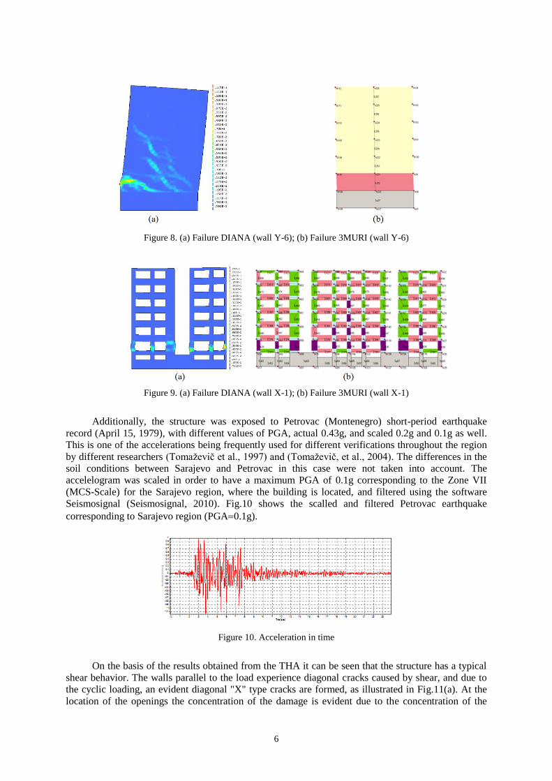
Figure 8. (a) Failure DIANA (wall Y-6); (b) Failure 3MURI (wall Y-6)
Figure 9. (a) Failure DIANA (wall X-1); (b) Failure 3MURI (wall X-1)
Additionally, the structure was exposed to Petrovac (Montenegro) short-period earthquake
record (April 15, 1979), with different values of PGA, actual 0.43g, and scaled 0.2g and 0.1g as well.
This is one of the accelerations being frequently used for different verifications throughout the region
by different researchers (Tomaževič et al., 1997) and (Tomaževič, et al., 2004). The differences in the
soil conditions between Sarajevo and Petrovac in this case were not taken into account. The
accelelogram was scaled in order to have a maximum PGA of 0.1g corresponding to the Zone VII
(MCS-Scale) for the Sarajevo region, where the building is located, and filtered using the software
Seismosignal (Seismosignal, 2010). Fig.10 shows the scalled and filtered Petrovac earthquake
corresponding to Sarajevo region (PGA0.1g).
Figure 10. Acceleration in time
On the basis of the results obtained from the THA it can be seen that the structure has a typical
shear behavior. The walls parallel to the load experience diagonal cracks caused by shear, and due to
the cyclic loading, an evident diagonal "X" type cracks are formed, as illustrated in Fig.11(a). At the
location of the openings the concentration of the damage is evident due to the concentration of the

N.Ademović and M.Hrasnica 7
stresses as seen in Fig.11(b). As it can be noticed in Fig.11(b) at the end of the earthquake action
major damage, besides the structural walls (Y direction), that are governing the behavior of the
structure, are seen at the façade walls and mainly at the lower levels.
Figure 11. (a) Damage pattern W-Y6; (b) Damage patternW-X1
The major concentration of the damage is located between the basement and the ground floor,
which can be connected with the discontinuity and large difference in the stiffness. Large damage is
observed in the lower floors where the largest inter-story drift was observed, as shown in Fig.12(a),
imposing severe deformation and ductility demand at these walls.
Fig.12(b) shows a part of the hysteresis curves for these three different cases of ground
acceleration (0.43g, 0.2g and 0.1g) as well as the capacity curve obtained from the Pushover Analysis
for Y direction. As it can be seen the structure has a relatively small displacement during the
earthquake with the PGA of 0.1g. It is evident that significant damage and energy dissipation occurred
during the ground movement corresponding to the acceleration of 0.2g, while the structure collapsed
during the real Petrovac earthquake record. It should be pointed out that during the earthquake action
of 0.2g values of the inter-story drift are unacceptable, so the structure is not safe (Ademović, 2012).
For 0.1g earthquake acceleration the maximum displacement in the value of 11.38mm as seen in
Fig.12(a) and Fig.12(b) is observed at the last floor. The biggest rise in the inter-storey drift is
observed at the ground level, at the height of 2.8m, being equivalent to 0.51%, as shown in Fig.12(a).
The cause of damage in walls is a high value of the drift. The rise in the drift values is a sign of deep
changes in stiffness. The envelope shows the largest storey drift is 0.78% located at the second floor
(8.4m), which is consistent to the damage patter shown before. Smaller damage is observed at the
upper floors where the inter-storey drift is smaller, so a good correspondence is observed.
Figure 12. (a) Inter-story drift for 0.1g; (b) Part of the hysteresis curves and pushover
Similar behavior has been identified by the previous earthquakes on a similar structure in
Skopje as stated in the World Housing Encyclopedia (2002), and illustrated in Fig.13(a), and well as in
the experiments done in Slovenia as shown in Fig.13(b) (Tomaževič et al., 1999). Good correlation of
the modelled structure in FEM and structure exposed to Skopje earthquake is more than evident.

8
Basement in the analyzed structure can be regarded as the first floor in the experiment procedure due
to a very high stiffness of the basement made out of reinforced concrete. The propagation of the
damage in the experiment slowly expands to the upper floors.
Figure 13. (a) Damage after Skopje earthquake (WHE, 2002); (b) Experiments (Tomaževič, et al., 1991)
3.2 Pushover Analysis 3MURI X-direction
As results obtained by EFM in "± Y" direction were in a very good consistency with the results
obtained by FEM, due to time issues the Pushover Analysis for "± X" direction was performed only
using Equivalent Frame Method.
As the structure has a rather inferior resistance in X direction, the first crack appeared already at
4.5% of the force, whereas the maximum coefficient horizontal
vertical
FF
reached only 9%, as
shown in Fig.14(a) (Ademović and Oliviera, 2012). Failure of the façade walls is due to bending and
compression failure at the ground level, as illustrated in Fig.14(b) and explained in Fig.15.
Figure 14. (a) Capacity curve for "± X" direction; (b) Failure pattern
Figure 15. Legend
N.Ademović and M.Hrasnica 9
3.3 Strengthening Procedure and Analysis
The typical residential multi-storey masonry structure in Bosnia and Herzegovina that has been
investigated indicated the major deficiencies of these types of structures being lack of structural walls
in longitudinal direction.
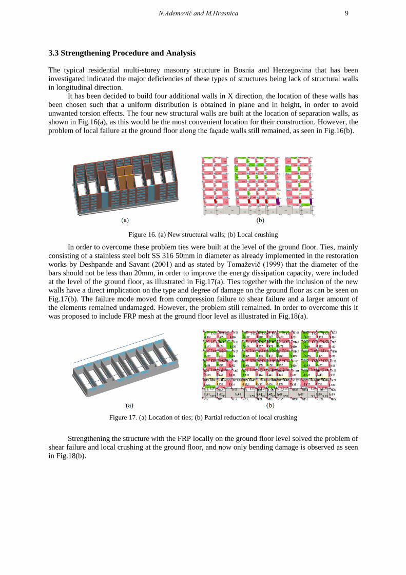
It has been decided to build four additional walls in X direction, the location of these walls has
been chosen such that a uniform distribution is obtained in plane and in height, in order to avoid
unwanted torsion effects. The four new structural walls are built at the location of separation walls, as
shown in Fig.16(a), as this would be the most convenient location for their construction. However, the
problem of local failure at the ground floor along the façade walls still remained, as seen in Fig.16(b).
Figure 16. (a) New structural walls; (b) Local crushing
In order to overcome these problem ties were built at the level of the ground floor. Ties, mainly
consisting of a stainless steel bolt SS 316 50mm in diameter as already implemented in the restoration
works by Deshpande and Savant (2001) and as stated by Tomaževič (1999) that the diameter of the
bars should not be less than 20mm, in order to improve the energy dissipation capacity, were included
at the level of the ground floor, as illustrated in Fig.17(a). Ties together with the inclusion of the new
walls have a direct implication on the type and degree of damage on the ground floor as can be seen on
Fig.17(b). The failure mode moved from compression failure to shear failure and a larger amount of
the elements remained undamaged. However, the problem still remained. In order to overcome this it
was proposed to include FRP mesh at the ground floor level as illustrated in Fig.18(a).
Figure 17. (a) Location of ties; (b) Partial reduction of local crushing
Strengthening the structure with the FRP locally on the ground floor level solved the problem of
shear failure and local crushing at the ground floor, and now only bending damage is observed as seen
in Fig.18(b).

10
Figure 18. (a) FRP mesh at the ground floor; (b) Elimination of local crushing
Comparing the capacity curves of the current structure and different proposed strengthening
techniques it is observed that ties have a beneficial effect on the increase of the structure capacity.
However, the problem of the shear failure and local crushing remained at the ground level. This was
solved by strengthening the structure locally with the FRP on the ground floor level. Comparison of
different strengthening methods and their implication on the capacity is shown in the Fig. 19.
0
5
10
15
20
25
0 5 10 15 20
Lo
ad
co
eff
icie
nt
[]
in %
Displacement [mm]
Original structure
Addition of 4 new walls and a tie
Additional 4 walls
Addition of 4 new walls and FRP on ground floor
Figure 19. Pushover curve – different strengthening proposals
4. CONCLUSION
A typical multi-storey masonry residential building in Sarajevo as part of the massive construction
during the 50's and 60's in the Western Balkans was analysed in two numerical models of rather
different scale. Utilizing FEM the structure is modeled as a non-linear continuum by finite elements,
while in EFM the structure is formed from assembly of structural elements as blocks upon which the
non-linear behavior is assigned. This has a direct implication on the mesh of the structure, definition of
the constitutive law and mechanical properties. On the basis of the performed calculations it has been
seen that for this particular case EFM gives quite good results. The modelling procedure is much
simpler and calculation time highly reduced in respect to FEM.
The structure has a high resistance in Y direction as all the structural walls are located in
transversal direction. However, the structure has inferior resistance in the X (longitudinal) direction, as
there are only two interior structural walls without openings. Globally the structure is weak in
longitudinal direction. In the case of stronger earthquake motion heavy damage could be expected so
strengthening has been proposed.
Several strengthening methods were analysed. In order to increase the stiffness in the X
direction it was necessary first to built additional walls. However, strengthening by inclusion of new
walls was insufficient in respect to the localized damaged in the ground floor level. This was partly
solved by adding ties at the level of the ground floor. The localized damage was highly reduced.
However, the problem of the shear failure and local crushing still remained. Addition of ties could not

N.Ademović and M.Hrasnica 11
solve this issue. In order to overcome this problem, at the ground level local strengthening was
conducted with FRP. With this type of strengthening only bending damage has been observed.
Globally structure strengthened with ties has a higher capacity in respect to the FRP
strengthening. However, the problem of the localized damage still remained. Strengthening the
structure with new walls and addition of FRP locally (ground floor) is more effective. The mode of
failure moved from shear failure to bending damage which is a more acceptable failure mode of
masonry structure.
REFERENCES
Ademović N, Hrasnica M (2013) “Seismic Assessment of a Multi-storey Masonry Building”, Proceedings of the
International Conference - Skopje Earthquake - 50 Years of European Earthquake Engineering" (SE-
50EEE), Skopje, Macedonia, Abstract Number.248: 1-8
Ademović N, Hrasnica M, Oliveira V D (2013) “Pushover analysis and failure pattern of a typical masonry
residential building in Bosnia and Herzegovina”, Engineering Structures, 50: 13-29
Ademović N, and Oliveira V D (2012) “Seismic Assessment of a Typical Masonry Residential Building in
Bosnia and Herzegovina”, Proceedings of the 15th
World Conference on Earthquake Engineering, Lisbon,
Portugal: 1-10
Ademović N (2012) Behaviour of Masonry Structures in Bosnia and Herzegovina at the Effect of Earthquakes
from the Viewpoint of Modern Theoretical and Experimental Knowledge, PhD Thesis, Faculty of Civil
Engineering, University of Sarajevo, Bosnia and Herzegovina (in Bosnian)
Ademović N (2011) Structural and Seismic Behavior of Typical Masonry Buildings from Bosnia and
Herzegovina. Master Thesis, Advanced Masters in Structural Analysis of Monuments and Historical
Constructions, University of Minho, Portugal
Chopra A K (2011) Dynamics of Structures, 4th
Ed., Prentice Hall, New Jersey
Deshpande S C, Savant Sandhya (2001) “Restoration of Capela da Nossa Senhora do Monte - Old Goa”,
Historical Constructions, Lourenço P B , Roca P (Eds.), Guimarães: 1081-1090
DIANA 9.4, TNO (2009) Displacement method ANAlyser 9.4. Finite element analysis. User’s Manual, release
9.4. Netherlands: s.n., Vol. Release 9.4
ICOMOS - International Council on Monuments and Sites (2003-2011) Recommendations for the Analysis,
Conservation and Structural Restoration of Architectural Heritage. http://www.icomos.org/.
IMK (2010) Report on the state and damage degree of the structure in street Zagrebačka no.5 in Sarajevo,
Institute for Materials and Structures, Faculty of Civil Engineering, Bosnia and Herzegovina (in Bosnian)
Hrasnica M (2009) Damage assessment of masonry and historical buildings in Bosnia and Herzegovina. In:
Ibrahimbegovic´ , Zlatar, editors. Chapter in: Damage assessment and reconstruction after war or natural
disasters. Springer Verlag: 333–56.
Mendes N and Lourenço Paulo B (2010) “Seismic Assessment of Masonry "Gaioleiro" Building in Lisbon,
Portugal”, Journal of Earthquake Engineering, 14:80–101
Petrovski T Jakim (2003) “Damaging Effects of July 26, 1963 Skopje Earthquake”, Proceedings of the
International Conference 40 years 1963 Skopje Earthquake, European Earthquake Engineering (SE-
40EEE): 1-16
Seismosignal (2010) Earthquake Engineering Software Solutions, Version 4.2.1.
S.T.A. DATA 3 Muri. (2010). Manual , STA DATA srl, Torino
Tomaževič M, Bosiljkov V, Polona W (2004) “Structural Behavior Factor for Masonry Structures” Proceedings
of the 13th
World Conference on earthquake Engineering. Vol. paper 2642, Vancouver
Tomaževič M (1999) Earthquake-Resistant Design of Masonry Buildings 1st Ed., Imperial College Press, Tom. I,
London
Tomaževič M, Iztok K (1997) “Verification of Seismic Resistance of Confined Masonry Buildings” Earthquake
Engineering and Structural Dynamics, Vol. 26: 1073-1088
WHE (2002) World Housing Encyclopedia Unreinforced Brick Masonry Apartment Building, Report No. 73.
Ljubljana, Housing Report