seikaku technical group limited
TRANSCRIPT

SEIKAKU TECHNICAL GROUP LIMITED
2014.09.22
A3 A4 A5
-RS
D-150.2 D-300.2 SHOW_V1.1
0.07KG/1
NH00231 1:2
5PCS
10
D-150.2
SHOW
NF04149
QHFBE004-20140900010,A,1

User's Manual
SWITCHING POWER PROFESSIONAL AMPLIFIER
D-150.2 / D-300.2
NF04149-1.1

PROFESSIONAL AMPLIFIER
Please read this manual carefully before operating this unit for the first time.
IMPORTANT!
INDEX
SAFETY RELATED SYMBOLS
WARNING
INTRODUCTION
01
02
04
03 IMPORTANT SAFETY INSTRUCTION
05
06
08
07
1
1
2
CONTROL ELEMENTS
3
4
7
10
APPLICATIONS
WIRING CONNECTIONS
09
12
13
BLOCK DIAGRAM
TECHNICAL SPECIFICATINS
PROFESSIONAL AMPLIFIER
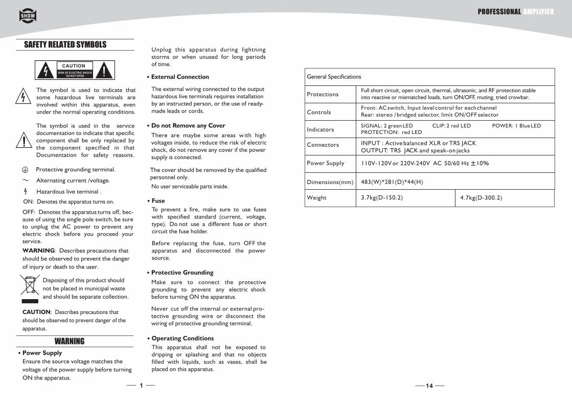
SAFETY RELATED SYMBOLS
CAUTION
RISK OF ELECTRIC SHOCKDO NOT OPEN
The symbol is used to indicate that some hazardous live terminals are involved within this apparatus, even under the normal operating conditions.
The symbol is used in the service documentation to indicate that specific component shall be only replaced by the component specified in that Documentation for safety reasons.
Protective grounding terminal.
Alternating current /voltage.
ON: Denotes the apparatus turns on.
OFF: Denotes the apparatus turns off, bec-ause of using the single pole switch, be sure to unplug the AC power to prevent any electric shock before you proceed your service.
WARNING: Describes precautions that
should be observed to prevent the danger
of injury or death to the user.
CAUTION: Describes precautions that
should be observed to prevent danger of the
apparatus.
WARNING
Power Supply
Ensure the source voltage matches the
voltage of the power supply before turning
ON the apparatus.
Unplug this apparatus during lightning storms or when unused for long periods of time.
External Connection
The external wiring connected to the output hazardous live terminals requires installation by an instructed person, or the use of ready-made leads or cords.
Do not Remove any Cover
There are maybe some areas w ith high voltages inside, to reduce the risk of electric shock, do not remove any cover if the power supply is connected.
The cover should be removed by the qualified personnel only.
No user serviceable parts inside.
Fuse
To prevent a fire, make sure to use fuses with specified standard (current, voltage, type). Do not use a different fuse or shortcircuit the fuse holder.
Before replacing the fuse, turn OFF the apparatus and disconnected the power source.
Protective Grounding
Make sure to connect the protective grounding to prevent any electric shock before turning ON the apparatus.
Never cut off the internal or external pro-tective grounding wire or disconnect the wiring of protective grounding terminal.
Operating Conditions
Hazardous live terminal .
Disposing of this product should
not be placed in municipal waste
and should be separate collection.
This apparatus shall not be exposed to dripping or splashing and that no objects filled with liquids, such as vases, shall be placed on this apparatus.
1 14
General Specifications
Protections
Controls
Full short circuit, open circuit, thermal, ultrasonic, and RF protection stable into reactive or mismatched loads, turn ON/OFF, muting, tried crowbar.
Front: AC switch, Input level control for each channelRear: stereo / bridged selector, limit ON/OFF selector
IndicatorsSIGNAL: 2 green LED CLIP: 2 red LED POWER: 1 Blue LED PROTECTION: red LED
Connectors
Power Supply
Dimensions(mm)
INPUT : Active balanced XLR or TRS JACKOUTPUT: TRS JACK and speak-on jacks
110V-120V or 220V-240V AC 50/60 Hz 10%
483(W)*281(D)*44(H)
Weight 3.7kg(D-150.2) 4.7kg(D-300.2)
PROFESSIONAL AMPLIFIER
2
Servicing
Refer all servicing to qualified personnel. To reduce the risk of electric shock, do not perform any servicing other than that contained in the operating instructions unless you are qualified to do so .
Servicing is required wh en the apparatus has been damaged in any way , such as power supply cord or plug is damaged , liquid has been spilled or objects have fallen into the apparatus, the apparatus has been exposed to rain or moisture , does not operate normally, or has been dropped.
To reduce the risk of fire or electric shock, do not expose this apparatus to rain or moisture.
Do not use this apparatus near water.Install in accordance with the manufacture-r's instructions. Do not install near any heat sources such as radiators, heat registers, stoves, or other apparatus (including am-plifiers) that produce heat. Do not block any ventilation openings.
IMPORTANT SAFETY INSTRUCTIONS
Read these instructions.
Keep these instructions.
Heed all warnings.
Only use attachments/accessories spec-
ified by the manufacturer.
Power Cord and Plug
Do not defeat the safety purpose of the
polarized or grounding type plug.
A polarized plug has two blades with one wider than the other. A grounding type plug has two blades and a third grounding prong. The wide blade or the third prong are provided for your safety. If the provided plug does not fit into your outlet, consult an electrician for replace-ment of the obsolete outlet.
Protect the power cord from being walk-ed on or pinched particularly at plugs, convenience receptacles, and the point where they exit from the apparatus.
Cleaning
When the apparatus needs a cleaning, you
can blow off dust from the apparatus with
Follow all instructions.
No naked flame sources, such as lighted
candles, should be placed on the apparatus.
a blower or clean with rag etc.
Don't use solvents such as benzol, alcohol, or other flu ids with very strong volatility and flammability for cleaning the apparatus body. Clean only with dry cloth.
The mains plug is used as the disconnect device,the disconnect device shall remain readily operable.
13
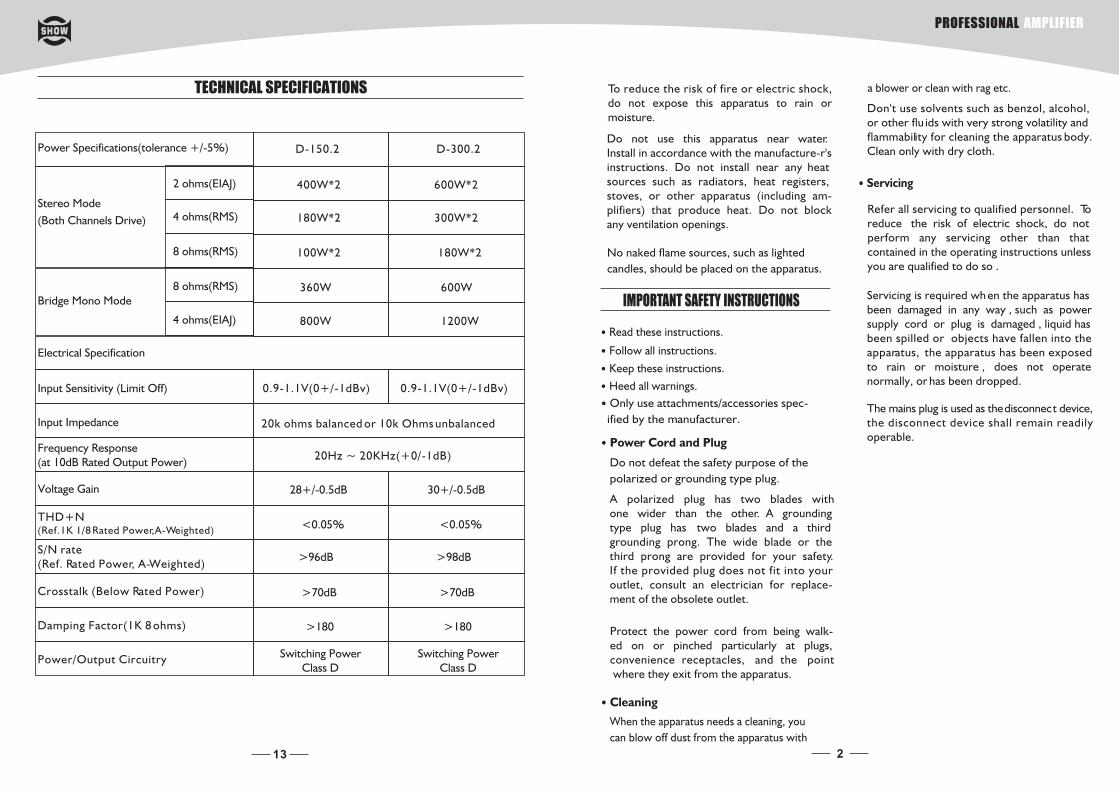
TECHNICAL SPECIFICATIONS
Power Specifications(tolerance +/-5%) D-150.2 D-300.2
Stereo Mode
(Both Channels Drive)
Bridge Mono Mode
2 ohms(EIAJ)
4 ohms(RMS)
8 ohms(RMS)
8 ohms(RMS)
4 ohms(EIAJ)
400W*2
180W*2
100W*2
600W*2
300W*2
180W*2
360W
800W
600W
1200W
Electrical Specification
Input Sensitivity (Limit Off) 0.9-1.1V(0+/-1dBv) 0.9-1.1V(0+/-1dBv)
Input Impedance 20k ohms balanced or 10k Ohms unbalanced
Frequency Response(at 10dB Rated Output Power)
20Hz ~ 20KHz(+0/-1dB)
Voltage Gain 28+/-0.5dB 30+/-0.5dB
THD+N(Ref.1K 1/8 Rated Power,A-Weighted)
<0.05% <0.05%
S/N rate(Ref. Rated Power, A-Weighted)
>96dB >98dB
Crosstalk (Below Rated Power) >70dB >70dB
Damping Factor(1K 8 ohms) >180 >180
Power/Output Circuitry Switching PowerClass D
Switching PowerClass D
PROFESSIONAL AMPLIFIER
3
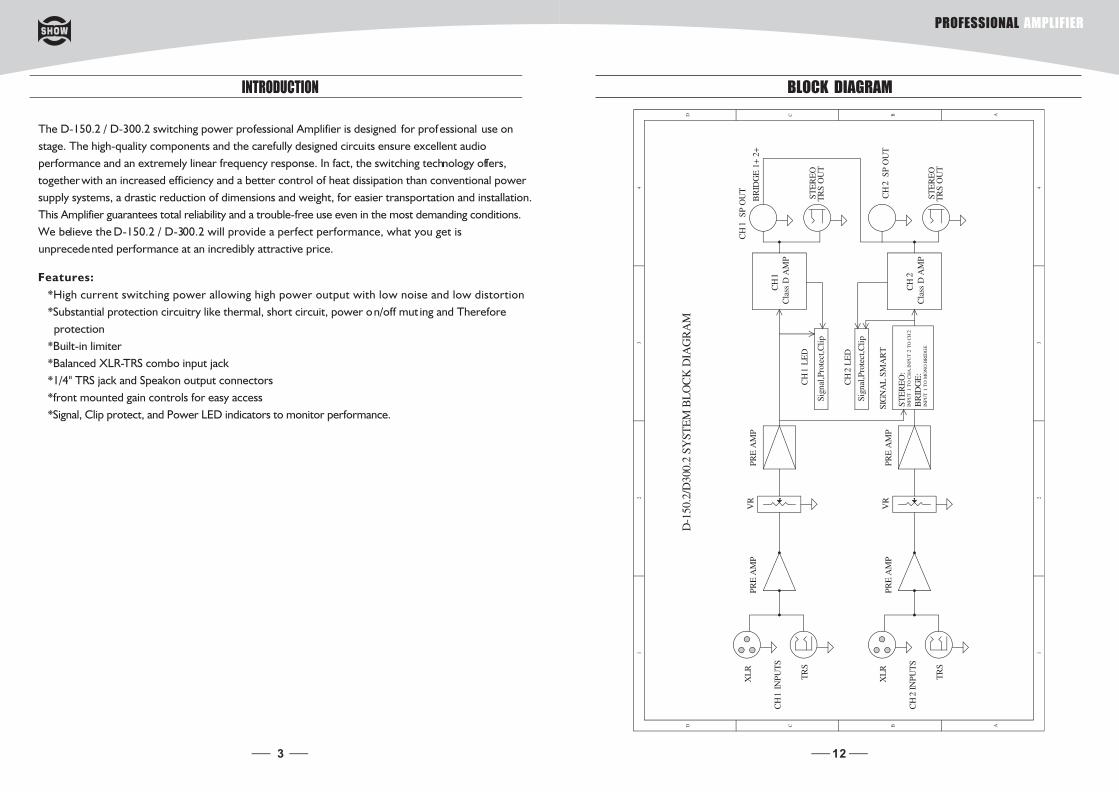
INTRODUCTION
The D-150.2 / D-300.2 switching power professional Amplifier is designed for professional use on
stage. The high-quality components and the carefully designed circuits ensure excellent audio
performance and an extremely linear frequency response. In fact, the switching technology offers,
together with an increased efficiency and a better control of heat dissipation than conventional power
supply systems, a drastic reduction of dimensions and weight, for easier transportation and installation.
This Amplifier guarantees total reliability and a trouble-free use even in the most demanding conditions.
We believe the D-150.2 / D-300.2 will provide a perfect performance, what you get is
unprecedented performance at an incredibly attractive price.
Features:
*High current switching power allowing high power output with low noise and low distortion
*Substantial protection circuitry like thermal, short circuit, power on/off mut ing and Therefore
protection
*Built-in limiter
*Balanced XLR-TRS combo input jack
*1/4" TRS jack and Speakon output connectors
*front mounted gain controls for easy access
*Signal, Clip protect, and Power LED indicators to monitor performance.
12
BLOCK DIAGRAM
PROFESSIONAL AMPLIFIER

4
Power Switch
It switches ON/OFF the unit main power.
Level Control
The Power LED lights up when the amplifier is powered ON.
Signal LED
These green LEDs light up when the respective channel's output signal pass through.
Protection LED
In normal operation, the Led will not illume; If the Led is red, it means the unit is in hea t protection,
no sound is output. The speaker system is actually disconnected from the ampl ifier outputs when
this LED is red, the temperature must be lowered by better ventilation and decrease the signal
level etc. if the problem is corrected, the protection systems deactivate automatically, and nor mal
amplifier operation is resumed.
These volume controls allow you to adjust the volume level.
Power LED
Clip LED
This red LED lights up when the input signal is too strong. it is time to reduce input level until cl ip
LED turning off.
6
5
4
3
2
1
Air Intake Vents 7
D-150.2 / D-300.2 employ a variable speed internal cooling fan to intake the air through front
grill to keep it running cool even under extreme operating conditions. Please keep these vents clear
and free from obstruction at all times to insure proper cooling.
CONTROL ELEMENTS
FRONT PANEL
11
Sleeve=Ground/Screen
Tip=Signal
Sleeve=Ground/Screen
Ring=Return Signal (Connected together)
To Channel Insert
To Tape or FX Input
'Tapped' Connection Direct Output Lead
(Enables the Insert to be used as a Direct Output
while maintaining the channel signal flow)
Sleeve
Sleeve=Ground/Screen
Ring=Return Signal
Tip=Send Signal
To Channel Insert
To Processor Input
To Processor Output
Ring
Tip
Y-Stereo lead for insert Connection
(To be used when the processor does not employ a single jack connection for the In/Out Connections)
PROFESSIONAL AMPLIFIER
110-120V110-120V
220-240V 220-240V
5
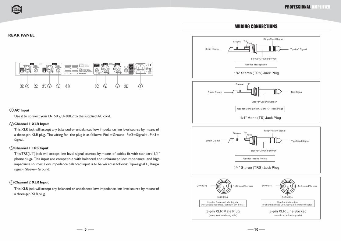
Use it to connect your D-150.2/D-300.2 to the supplied AC cord.
AC Input
Channel 1 TRS Input
This TRS(1/4') jack will accept line level signal sources by means of cables fit with standard 1/4"
phone plugs. This input are compatible with balanced and unbalanced low impedance, and high
impedance sources. Low impedance balanced input is to be wired as fol lows: Tip=signal+, R ing=
signal-, Sleeve=Ground.
This XLR jack will accept any balanced or unbalanced low impedance line level source by means of
a three-pin XLR plug. The wiring for the plug is as follows: Pin1=Ground, Pin2=Signal+, Pin3=
Signal-.
Channel 1 XLR Input
This XLR jack will accept any balanced or unbalanced low impedance line level source by means of
a three-pin XLR plug.
Channel 2 XLR Input
REAR PANEL
10
WIRING CONNECTIONS
Strain Clamp
Sleeve TipRing
Sleeve=Ground/Screen
Ring=Right Signal
Tip=Left Signal
Use for Headphone
1/4" Stereo (TRS) Jack Plug
Strain Clamp
Sleeve Tip
Sleeve=Ground/Screen
Tip=Signal
Use for Mono Line In, Mono 1/4"Jack Plugs
1/4" Mono (TS) Jack Plug
Strain Clamp
Sleeve TipRing
Sleeve=Ground/Screen
Ring=Return Signal
Tip=Send Signal
Use for Inserts Points
1/4" Stereo (TRS) Jack Plug
2=Hot(+)
3=Cold(-)
1=Ground/Screen
(seen from soldering side)
Use for Balanced Mic Inputs (For unbalanced use, connect pin 1 to 3)
3-pin XLR Male Plug
2=Hot(+)
3=Cold(-)
1=Ground/Screen
Use for Main output (For unbalanced use, leave pin 3 unconnected)
3-pin XLR Line Socket(seen from soldering side)
12
3
12
3
PROFESSIONAL AMPLIFIER
6
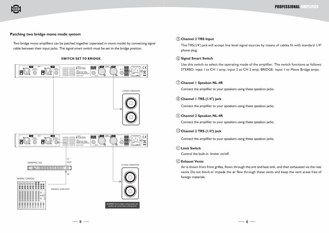
Channel 1 TRS (1/4") jack
Channel 2 Speakon NL-4R
Connect the amplifier to your speakers using these speakon jacks.
Channel 2 TRS (1/4") jack
Limit Switch
Control the built-in limiter on/off.
Exhaust Vents
Air is drawn from front grilles, flown through the unit and heat sink, and then exhausted via the rear
vents. Do not block or impede the air flow through these vents and keep the vent areas free of
foreign materials.
Channel 2 TRS Input
This TRS(1/4') jack will accept line level signal sources by means of cables fit with standard 1/4"
phone plug.
Signal Smart Switch
Use this switch to select the operating mode of the amplifier. The switch functions as follows:
STEREO: input 1 to CH 1 amp, input 2 to CH 2 amp; BRIDGE: input 1 to Mono Bridge amps.
Channel 1 Speakon NL-4R
Connect the amplifier to your speakers using these speakon jacks.
Connect the amplifier to your speakers using these speakon jacks.
Connect the amplifier to your speakers using these speakon jacks.
110-120V110-120V
220-240V 220-240V
110-120V110-120V
220-240V 220-240V
9
Two bridge mono amplifiers can be patched together (operated in mono mode) by connecting signal
cable between their input jacks. The signal smart switch must be set to the bridge position.
Patching two bridge mono mode system
PROFESSIONAL AMPLIFIER
110-120V110-120V
220-240V 220-240V
7
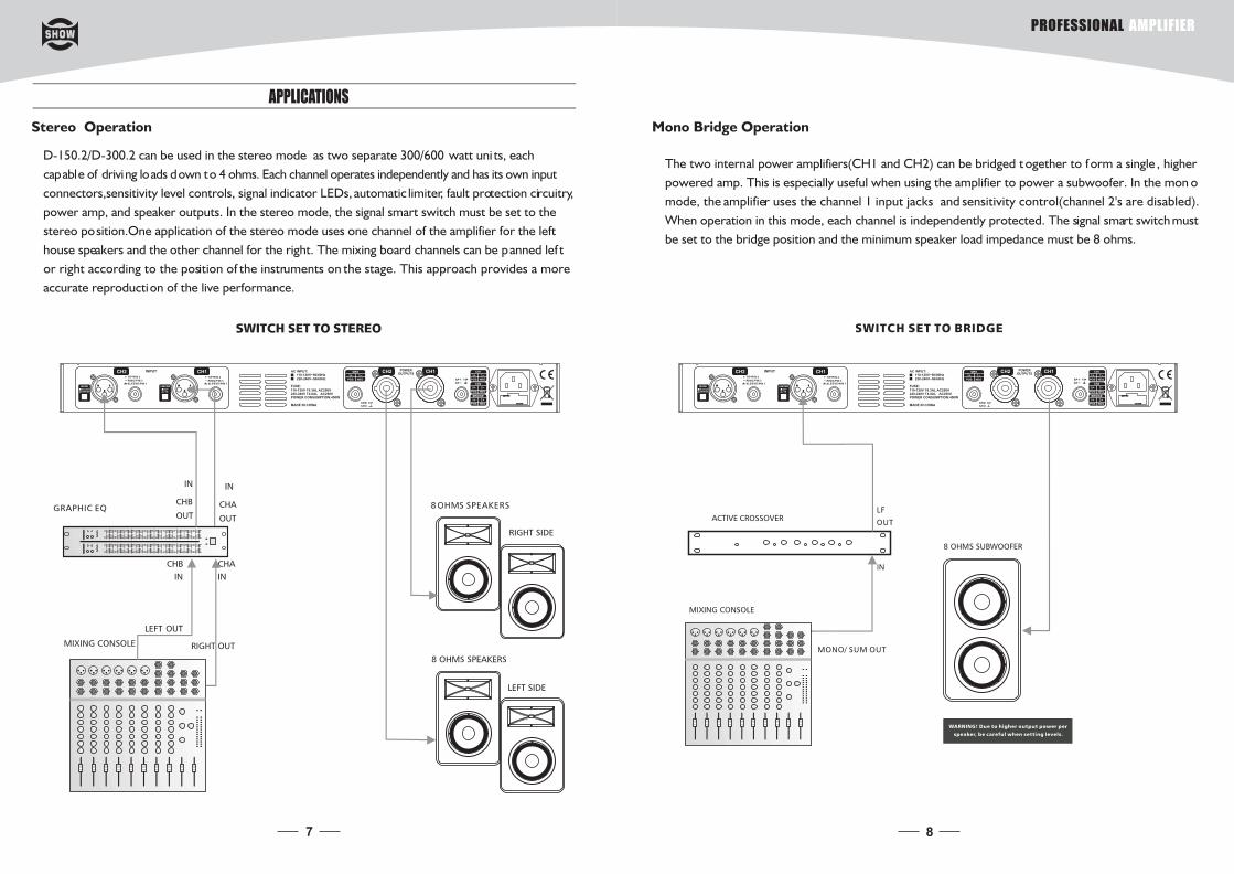
APPLICATIONS
Stereo Operation
D-150.2/D-300.2 can be used in the stereo mode as two separate 300/600 watt uni ts, each
capable of driving loads down to 4 ohms. Each channel operates independently and has its own input
connectors,sensitivity level controls, signal indicator LEDs, automatic limiter, fault protection circuitry,
power amp, and speaker outputs. In the stereo mode, the signal smart switch must be set to the
stereo position.One application of the stereo mode uses one channel of the amplifier for the left
house speakers and the other channel for the right. The mixing board channels can be panned lef t
or right according to the position of the instruments on the stage. This approach provides a more
accurate reproduction of the live performance.
110-120V110-120V
220-240V 220-240V
8
The two internal power amplifiers(CH1 and CH2) can be bridged t ogether to form a single , higher
powered amp. This is especially useful when using the amplifier to power a subwoofer. In the mon o
mode, the amplifier uses the channel 1 input jacks and sensitivity control(channel 2's are disabled).
When operation in this mode, each channel is independently protected. The signal smart switch must
be set to the bridge position and the minimum speaker load impedance must be 8 ohms.
Mono Bridge Operation
PROFESSIONAL AMPLIFIER