seed-layout tutorialujf/download_files/sl_tutorial.pdfseed-layout tutorial ulrich flemming ... the...
TRANSCRIPT
SEED-Layout Tutorial
Ulrich Flemming
School of Architecture andInstitute for Complex Engineered SystemsCarnegie Mellon UniversityPittsburgh, PA 15213
Jan. 31, 1999

1. Introduction 1
Overview 1Purpose of tutorial 1Intended tutorial audience2How to approach this tutorial2Text formatting conventions used in tutorials2What is SEED-Layout? 3Task 3Preview 5
2. Session 1: SEED-LayoutFundamentals 7
Overview 7Getting Started 7The SEED-Layout Design Window8Functional Units - Design Units9Layout Problems 12Walls 13The Layout Tree 15Layout Generation - Review16Changing the Allocation Order16Rearranging a Layout17Finalize 18A Closer Look at the Add Design UnitCommand 19Problem Modification 21Extended Exercise22
3. Session 2: Hierarchical LayoutGeneration 25
Overview 25Constituent Hierarchies25Sublayout Problems26The Problem Hierarchy 27
SEED-Layout Tutorial Manual 3

4
Vertical Zones 30More Functional Unit Types 31Functional Unit Types: Summary33SEED-Layout Output 35Extended Exercise36
4. Session 3: The SEED-Layout DesignSpace 37
Overview 37A Simple Design Space37Subproblems and Subspaces38Alternative Subproblems and Subspaces40Variant Layout Problems and Design Spaces41Extended Exercise43
SEED-Layout Tutorial Manual
re
ines
useoutasic
lt to
ry.
me
t o and
eateevels
1. Introduction
1.1 Overview
Welcome to the tutorial for a software application called SEED-Layout. This softwawas developed within the School of Architecture at Carnegie Mellon University. Itsintended area of application is the schematic phase of layout design, which determthe overall organization and configuration of a planned building.
In this chapter we will explain the basic task addressed by SEED-Layout. We willthe following tutorial chapters to introduce the basic concepts underlying SEED-Layand its capabilities in a structured, step-by-step fashion. The tutorial stars with very bconcepts and operations and progresses to concepts and operations of increasingcomplexity. The chapters build upon each other so that later chapters will be difficuunderstand if the material presented in earlier chapters has not been mastered.
We assume in this tutorial that the user has installed the latest working versionof SEED-Layout on a Windows 2000 or Windows XP computer. In order to gain themost from the tutorial, the user is expected to complete the exercises as described.Several of these exercises rely on data files residing under the "data" folder or directo
1.2 Purpose of tutorial
This tutorial has the following goals:
• Introduce the schematic layout software tool called SEED-Layout and explain soof its conceptual underpinnings
• Provide examples of how SEED-Layout is intended to be used, showing inputsoutputs from the tool
• Introduce the SEED-Layout user interface and how users can interact with it to crschematic layouts. This is done by providing a series of exercises at increasing lof difficulty and complexity.
SEED-Layout Tutorial Manual 1
Introduction
che-
lore
sup-
pro-for
thender-
ein-ent
der-out.
er-ceptsheyay
1.3 Intended tutorial audience
The following tutorial is meant to suit the following audiences:
• Those who may need to use SEED-Layout to perform a practical architectural smatic layout task.
• Those who are presently engaged in preliminary building design and wish to exphow SEED-Layout might assist this process
• Those who wish to familiarize themselves with the generative approach to designport, of which the SEED tools are good examples.
• Those who wish to study also the capabilities of SEED-Pro, the architecturalgramming module of SEED. One purpose of SEED-Pro is to generate inputSEED-Layout in the form of an architectural program that forms the basis forschematic layout task. The concepts underlying SEED-Pro are much better ustood if users know how SEED-Layout will eventually make use of them.
1.4 How to approach this tutorial
The following approach is recommended:
• Test whether your PC copy of SEED-Layout can be launched properly. If not, rstall the application and pay attention to the proper setting of the SEED environmvariables, without which SEED-Layout will not launch successfully on a PC.
• Finish reading the introduction to this tutorial manual in order to get a better unstanding of what ‘schematic layout design’ means in the context of SEED-LayMake sure that the SEED-Layout Reference Manual is in easy reach.
• Complete the SEED-Layout tutorial chapters in the given order including all excises. It is advised that you do this over more than one day because some conused in SEED-Layout are novel and not part of traditional architectural practice. Twere introduced in order to take full advantage of the computer’s power, but it mtake some time until they fully ‘sink in’.
• Progress to the SEED-Pro tutorial if you so wish.
1.5 Text formatting conventions used in tutorials
In the exercises, we observe the following text formatting conventions:
2 SEED-Layout Tutorial Manual

What is SEED-Layout?
iated
oft-
own
n are
t. Itetsyzero-
; wext.s tos
ntext
the of)
hisers
• Windows and menu items to be selected or opened in SEED-Layout are abbrevas follows:From Menu:Specifications > Edit Buildings > New Building...This means the following:From the ‘Specifications’menu, select the‘Edit Buildings’ sub-menu, then selectthe ‘New Building...’ command. These types of abbreviations are common in sware tutorials and reference manuals and should be easy to follow.
• Words intended to be entered by the user into a SEED-Layout dialog box are shin a fixed-width font: e.g. enter:Clinic.
• Definitions of technical terms or concepts that require a more detailed explanatioshown as follows:
SEED-Layout An application which assists the schematic layout phase in building design.
1.6 What is SEED-Layout?
SEED-Layout is one of the software applications comprising the SEED environmenspecifically assists architects in the schematic layout phase in which they derive thoverall building organization and configuration (which will eventually include aspecof site design). SEED-Layout is meant to support an exploratory mode of design bencouraging architects to derive and compare conceptual alternatives before they in on a specific design concept.
1.7 Task
Schematic layout design is an integral component of the early building design phaseoutline in the present section briefly how this task is understood in the SEED conteThe succeeding chapters introduce you to the specific concepts SEED-Layout usesupport this task and to the operations it offers the user to create schematic layoutrapidly.
Figure 1 shows examples of schematic layouts as the term is understood in the coof SEED-Layout. Schematic layouts are typically drawn with ‘center-lines’, whichdelineate the important functional areas and major circulation elements on a floor. Infinished design, physical spatial enclosures and partitions may be placed on (partsthe center lines and will then have a positive thickness. But a center line drawingabstracts from such details. It is typically drawn at 1/16” or, metrically, 1/200 scale; tscale makes it difficult to represent physical building elements, while helping designunderstand how the overall building is organized and how it fits into the site andsurrounding context.
SEED-Layout Tutorial Manual 3

Introduction
ing,
bothesext;
aretion.eers,
nd
The schematic layouts of the various floors of a building indicate its overall masswhich influences - among other aspects - its performance with respect to energyconsumption or costs. They determine also basic circulation or movement patterns,on a floor and between floors. Aside from such functional and practical aspects, thlayouts determine the overall form of the building and how it fits into the given contethey are thus an important indicator of the architect’s formal or expressive intent.
Especially larger buildings are often divided into distinct parts. The firestations inFigure 1 consist, for example, of a central apparatus room and two wings. The wingslower than the central part, require an independent roof, and have their own foundaThis organization is a standard scheme developed by the US Army Corps of Enginone of the main sponsors of SEED, for firestations built on Army bases.
The second example in Figure 1, the first floor of Herring Hall at Rice University,illustrates another important organizational strategy found specifically in largerinstitutional buildings, zoning. Herring Hall is clearly organized into parallel zones,which determine basic circulation patterns; they also influence the structural grid athermal zones that the structural and mechanical engineers, respectively, will use.
12 3 2
3
2
5
4
6 7
1
9
5
7
6
12 10
13
1514 11
134
2
8
8 8
8
1
95
8
7
6
12 10
13 13
1514 11
13
4
28
Firestation prototypes (Source: Department of the Army, Design Guide for Fire Stations)
Herring Hall, Rice University, Houston, TX, C. Pelli, arch. (Source: Progressive Architecture, 4(1985))
3
13 13
3
13 13 13
1 Mech2 Case Room3 Seminar Room4 Arcade5 Lecture Hall6 Courtyard7 Reading Room8 Stair
1 Apparatus Room2 Shift Leader’s Office3 Kitchen4 Fire Inspector’s Office5 Dayroom6 Watch/Alarm7 Training8 Chief’s Suite9 Dining10 Mechanical Equipment11 Physical Training12 Workroom13 Dorm14 Female Bath15 Male Bath
20’ 60’0’
FIGURE 1. Examples of schematic layouts
4 SEED-Layout Tutorial Manual
Preview
e in
nterngs
f
ngs.
d in
The zones clearly exert a strong influence on the overall massing and form of thbuilding: they are articulated as distinct parts through independent roofs, variationsmaterials etc. and can be ‘read’ as such from the outside. Zoning is thus anorganizational strategy likely to have far-reaching implications for the form andfunction of a building.
SEED-Layout supports schematic layout design at the level of detail found in celine drawings. It supports specifically the use of basic organizational devices like wior zones and is meant to encourage designers to experiment with alternativeorganizational strategies. To achieve this goal, it provides designers with a range ogeneration and evaluation capabilities that can be activated with ease and in anycombination.
1.8 Preview
Session 1: SEED-Layout FundamentalsBasic concepts and commands introduced in the context small single-storey buildi
Session 2: Hierarchical Layout GenerationSEED-Layout’s way to handle multi-storey buildings, zones and other buildingsubdivisions.
Session 3: The SEED-Layout Design SpaceThe most complex notion used by SEED-Layout is that of a design space, introducethis section. If you master this section, you’re home free.
SEED-Layout Tutorial Manual 5

Introduction
6 SEED-Layout Tutorial Manual

als
gn?
ut in
ute
e theor
ed)
ca-
2. Session 1: SEED-Layout Fundament
Prerequisites: none
Approximate time to complete:
2.1 Overview
This chapter concentrates on the following topics:
• SEED-Layout Problem and its parts: how does SEED-Layout know what to desi
• Schematic layouts and their generation: what are the parts of a schematic layoSEED-Layout and how can they be generated or placed?
In dealing with these issues, SEED-Layout relies on a few basic concepts: LayoProblem, Context, Functional Units, Design Units and Walls, which we will introducin this chapter.
We introduce these concepts in the context a very simple layout task: to generatlayout of a small clinic for ambulatory health care administered by a single physicianby two physicians with alternating schedules (see Figure 2).
2.2 Getting Started
1. Open the directory where the SEED-Layout executable is located (typically C:\se
2. Double-click on the SEED-Layout icon; after a short wait, the SEED-Layout applition opens.
FIGURE 2. Target Layout CLINIC
SEED-Layout Tutorial Manual 7
Session 1: SEED-Layout Fundamentals
t
me
at can this
Note:If SEED-Layout does not open at this point, it is likely that the required environmenvariables have not been set properly in your computer.
The readme.txt file provided as part of the SEED-Layout package contains instructionson how to set these variables.
2.3 The SEED-Layout Design Window
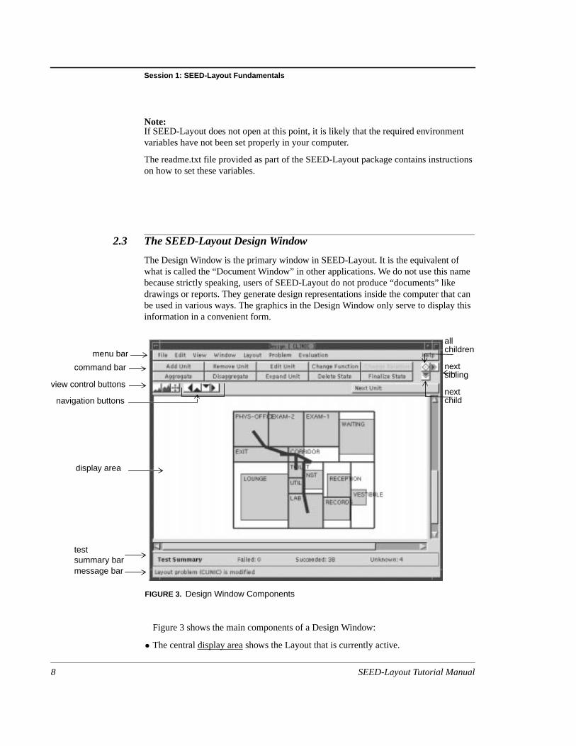
The Design Window is the primary window in SEED-Layout. It is the equivalent ofwhat is called the “Document Window” in other applications. We do not use this nabecause strictly speaking, users of SEED-Layout do not produce “documents” likedrawings or reports. They generate design representations inside the computer thbe used in various ways. The graphics in the Design Window only serve to displayinformation in a convenient form.
Figure 3 shows the main components of a Design Window:
• The centraldisplay area shows the Layout that is currently active.
menu bar
command bar
navigation buttons
view control buttons
testsummary barmessage bar
display area
FIGURE 3. Design Window Components
allchildren
nextsibling
nextchild
8 SEED-Layout Tutorial Manual
Functional Units - Design Units
.
ger
ign
fore
are
ob-
-
IC
ST
ut
ar.prisep ofed
n
ST
• Themenu bar contains pull-down menus containing sub-menus, items or options
• Thecommandbar contains two rows of command buttons that allow users to trigthe execution of specific design tasks.
• Generationbuttons at the right end of the command bar trigger the addition of DesUnits in a more automated mode.
• View control buttons allow users to zoom in or out or change the display scale.
• Navigation buttons allow users to activate Layouts that have been generated beand can easily be “reached” from the active Layout.
• Theunplacedunitsmenu can be used to change the order in which Design Unitsgenerated.
Load the Layout Problem that contains the spatial program for the clinic:
Steps:1. File > Load Problem... opens a file dialog box displaying the available Layout Pr
lems in the default directory or a directory structure. Navigate through data->PS_LIBuntil you find the Layout Problem file CLINIC-TUTORIAL.lp.
2. Click the Open button. SEED-Layout loads the CLINIC Layout Problem into memory and displays an initial Layout.
We will inspect the parts of a Layout Problem in the next exercises, using the CLINas an example.
2.4 Functional Units - Design Units
Inspect the Layout in the Design Window. Why does it show a rectangle labelled VEin the middle of a larger area?
In order to find an answer to that question, open another window called the LayoProblem Window:
Window > Layout Problem
Open the Constituent field by clicking the arrow button at the right end of the title bYou notice that it shows a list of names that designate the functional areas that comthe clinic we want to layout. The unit VEST, which stands for vestibule, is at the tothe list; that’s why it shows up in the initial Layout. Note also that the next unit is callWAIT.
Refocus the Design Window without closing the Layout Problem Window (you caalways reopen it if you closed it inadvertently). Click theNext Child navigation buttonat the lower right corner of the command bar. The layout is redrawn showing now VE
SEED-Layout Tutorial Manual 9
Session 1: SEED-Layout Fundamentals
itow.
ut
ewaintow;
w
AIT,ver
xs 8iche x-e
ct
and WAIT, with WAIT placed below VEST. You may guess that WAIT was the next unplaced because it followed VEST in the Constituent list in the Layout Problem Wind
But why are the units placed in the middle of the area shown? Refocus the LayoProblem Window and click on VEST in the Constituent field; the name will behighlighted. Click the right mouse button. This brings up a dialog box; select the ViConstituent option. This opens a Functional Unit Window. Inspect the Value Constrfield by opening it as you opened the Constituent filed in the Layout Problem Windnotice that it contains the following settings:
Min. width = 4; min. area = 16
Close the Functional Unit window for VEST and open the Functional Unit Windofor WAIT. Going through the same steps, you’ll notice
Min. width = 9; min. area = 150.
The values that we found are spatial requirements associated with VEST and Wrespectively. SEED-Layout tries to satisfy these requirements automatically whenethis is possible. How does it do this?
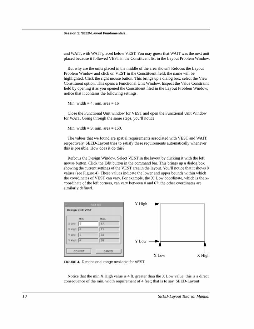
Refocus the Design Window. Select VEST in the layout by clicking it with the leftmouse button. Click the Edit button in the command bar. This brings up a dialog boshowing the current settings of the VEST area in the layout. You’ll notice that it showvalues (see Figure 4). These values indicate the lower and upper bounds within whthe coordinates of VEST can vary. For example, the X_Low coordinate, which is thcoordinate of the left corners, can vary between 0 and 67; the other coordinates arsimilarly defined.
Notice that the min X High value is 4 ft. greater than the X Low value: this is a direconsequence of the min. width requirement of 4 feet; that is to say, SEED-Layout
FIGURE 4. Dimensional range available for VEST
Y High
Y Low
X Low X High
10 SEED-Layout Tutorial Manual

Functional Units - Design Units
ghere
ThisThisefor
9e
uis ance,
isD:
le
ts.
re
ize a
henhave
ter. the
deduces from the requirement that the left x coordinate has to be at least 4 feet hithan the low x-coordinate. Try to understand the other coordinate values in the samway.
But notice also that the coordinates themselves have a great degree of variability.is due to the fact that not much has been placed in the area that is overall available.variability is SEED-Layout’s way of indicating that VEST is placed ‘somewhere’ in thplan. Before dismissing the Edit window, note that the maximum Y High coordinateVEST is 21.
Dismiss the Edit window by clicking the CANCEL button. Select WAIT in theLayout and open its Edit window. Try to understand its settings in terms of therequirements specified for WAIT. Notice also that its max y-coordinate is 32. Thisexplains why the min y-coordinate of VEST is only 9: since WAIT has to be at leastft. wide and since it is placed below VEST, VEST cannot get closer than 9 feet to thlower boundary of the layout. (We’ll see soon how we know that this is the lowerboundary).
We are now ready to introduce some fundamental concepts of SEED-Layout. Yohave noticed that there are two different elements that have the name VEST, one rectangle in a layout, and one is a constituent in a layout problem. What’s the differeand why do they have the same name?
Let’s start with the area labelled VEST in the layout. This is an instance of what called a Design Unit. This name has to be understood in the broader context of SEE
Design Unit A Design Unit (DU for short) is a building component. It may be spatial, like a vestibuor an office zone, or physical, like a window or a floor slab. Design Units are theprimary focus of design in SEED. SEED-Layout deals only with spatial Design Uni
The constituent called VEST is called a Functional Unit. Again, Functional Units aconcepts shared between the individual modules of SEED:
Functional Unit A Functional Unit (FU for short) collects all requirements that apply to a specificDesign Unit. SEED-Layout uses these requirements when it has to place, size or resDesign Unit.
Why separate Design and Functional Units? There are many reasons for thisseparation, which we will discuss during the exercises. For starters, observe that wwe generate layout alternatives, we can have Design Units in different layouts thatthe same associated Functional Unit. For example, we may have one alternative inwhich the vestibule is in the lower right corner, while in another plan, it’s in the cenSeparating the reqirements from the area to which they apply allows us to express
SEED-Layout Tutorial Manual 11

Session 1: SEED-Layout Fundamentals
nts
lnnal
m
nal
owout
e
D-
out:
ith
manyxplore
youts,
ons
requirements only once and in one place. This also allows us to edit the requiremeonce and then propagate them to all associated Design Units.One of the most basicfeatures you have to understand when working with SEED-Layout is the distinctionbetween Functional and Design Units.
When a Design Unit is placed to satisfy the requirements of a specific FunctionaUnit, we say that itallocatesthat Functional Unit. When drawing a layout in the DesigWindow, SEED-Layout simply labels each Design Unit with the name of the FunctioUnit it allocates.
Exercises:1. Inspect the requirements of some other constituents in the current Layout Proble
2. Without looking back, try to express in your own words what Design and FunctioUnits are and why we distinguish between them.
2.5 Layout Problems
One question remained from the preceding exercises: How does SEED-Layout knthat 36 ft. is the maximal y-coordinate in the overall available area? Refocus the LayProblem Window, close the Constituent Field and open the Context field. You’ll findeight attributes that look very similar to the coordinates that indicate the locationalpossibilities for a Design Unit. They have indeed a similar function: they indicate thvariability available in the overall area.
Observe that the maximum value for the high y-coordinate is 36 ft. That’s how SEELayout gets this value. More explanations...
We can now express succinctly what constitutes a Layout Problem in SEED-Lay
Layout Problem A Layout Problem consists of a Context and a list of constituent Functional Units wassociated requirements.
The task designers can set for themselves when working with SEED-Layout is togenerate layouts that allocate the Functional Units in the given Context so that as requirements as possible are satisfied. Designers are specifically encouraged to ealternative possibilities.
But what about requirements that deal with relationsbetween Functional Units? Theycan also be part of a Layout Problem. Inspect the Required Relations field in the LaProblem window. You’ll notice five bars labelled Adjacencies, Alternative AdjacencieDirections, Distances, Accessibilities, which indicate the five types of required relatiSEED-Layout is currently able to handle.
12 SEED-Layout Tutorial Manual
Walls
ao
ip
etesee
ant
thetheow:
ate
e
rectly?e ae
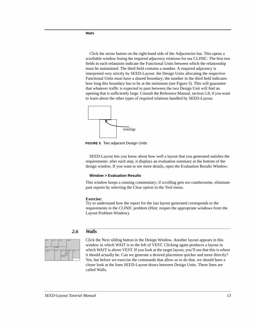
Click the arrow button on the right-hand side of the Adjacencies bar. This opensscrollable window listing the required adjacency relations for our CLINIC. The first twfields in each relatuioin indicate the Functional Units between which the relationshmust be maintained. The third field contains a number. A required adjacency isinterpreted very strictly by SEED-Layout: the Design Units allocating the respectivFunctional Units must have a shared boundary; the number in the third field indicahow long this boundary has to be at the minimum (see Figure 5). This will guarantthat whatever traffic is expected to pass between the two Design Unit will find anopening that is sufficiently large. Consult the Reference Manual, section 5.8, if you wto learn about the other types of required relations handled by SEED-Layout.
SEED-Layout lets you know about how well a layout that you generated satisfiesrequirements: after each step, it displays an evaluation summary at the bottom of design window. If you want to see more details, open the Evaluation Results Wind
Window > Evaluation Results
This window keeps a running commentary; if scrolling gets too cumbersome, eliminpast reports by selecting the Clear option in the Tool menu.
Exercise:Try to understand how the report for the last layout generated corresponds to therequirements in the CLINIC problem (Hint: reopen the appropriate windows from thLayout Problem Window).
2.6 Walls
Click the Next sibling button in the Design Window. Another layout appears in thiswindow in which WAIT is to the left of VEST. Clicking again produces a layout inwhich WAIT is above VEST. If you look at the target layout, you’ll see that this is wheit should actually be. Can we generate a desired placement quicker and more direYes, but before we exercise the commands that allow us to do that, we should havcloser look at the lines SEED-Layout draws between Design Units. These lines arcalled Walls.
overlap
FIGURE 5. Two adjacent Design Units
SEED-Layout Tutorial Manual 13

Session 1: SEED-Layout Fundamentals
at’so
ther.
oor:AIT
assert
nes
een
thenced.
willteititAIT
e
ut
tockisthe
Walls In a final layout, walls indicate lines on which physical walls can be placed, and thhow they got their name. But in intermediate layouts in which Design Units have nfixed locations, they play a somewhat different role: they indicatebasicspatialrelationsbetween Design Units that SEED-Layout will maintain in a specific layout.
The last three layouts we generated are different in that WAIT and VEST havedifferent relations, which are indicated by the walls separating the units from each o
You may also look at walls as the indicators of the basic zones you create on a flthe wall that cuts across the last layout establishes two parallel horizontal zones. Wand VEST are allowed to glide along the zone divider or to move to the right or leftmore units are added; but they will never cross the wall (unless you remove and reinone of the units). At this point, you have the option to continue these horizontal zothrough the rest of the layout; to restrict this zoning to only a part of the plan andintroduce another scheme in other portions; or to pursue a different zoning idea, inwhich case you will have go back to a different layout or generate one that has not bproduced so far.
If we now look at the target layout, we see that the horizontal zones established inlast layout are supposed to continue through its entire length. Knowing this, we castreamline the process by taking charge of where Design Units are going to be pla
What is the next Functional Unit scheduled for allocation? Look at the Next Unitbutton below the right end of the command bar: it displays the name of the unit thatbe placed next. In this particular case, it’s the CORRIDOR. If you look at the targelayout, the CORRIDOR is supposed to be in the upper zone, i. e. above VEST (albnot necessarily adjacent to it) and to the left of WAIT. We can tell SEED-Layout thatshould place the CORRIDOR in these relations to the existing units by selecting Wand the wall to the left of WAIT:
1. Click WAIT; it will be highlighted
2. Hold down SHIFT and click the left wall; it will be highlighted, too (you may reverssteps 1 and 2!)
3. Click the Add Unit button in the command bar.
SEED-Layout interprets this command with the present selections as follows: itallocates CORRIDOR by ‘pushing’ WAIT away from the selected wall. The new layoin the Design Window shows the result.
Let’s figure out how to place EXAM-1 in the desired position. It’s supposed to bethe left of WAIT and above CORRIDOR. Select WAIT and again its left wall and cliAdd. What happened? WAIT is pushed away from the left wall all right and EXAM-1inserted in the gap, but it’s placed between WAIT and the CORRIDOR, not above CORRIDOR.
14 SEED-Layout Tutorial Manual
The Layout Tree
tohesas
r that
et
out,D-
ntsene
ve
chnotany
reele:is
Let’s try another option. Click the Goto Parent navigation button. This returns usthe previous layout. Select CORRIDOR and the above wall and click Add: this pusCORRIDOR down from the above wall and places EXAM-1 above the CORRIDOR;a side effect, it places EXAM-1 in the desired relation with WAIT.
Observe that we have now established another horizontal zone above the corridois supposed to span between WAIT and the left boundary of the layout.
Exercise:Try to allocate EXAM-2 and PHYS (the physician’s office) in that zone. If you don’t git right the first time, keep on returning to the parent layout(s) until you succeed.
2.7 The Layout Tree
You may have guessed that it’s possible to revisit not only the parent layout of a laybut also other layouts that you generated before. This is indeed the case, and SEELayout provides two basic devices; the navigation buttons, of which the Goto Parebutton is a par, also contain a First Child, Last sibling and Next Sibling button. Try thefor the currently active Layout. We call this local navigation because you move only ostep away at a time from the currently active layout.
Try to return to the layout that was active at the beginning of this section. If you hatrouble finding it again, open the Layout Tree Window:
Window > Layout Tree.
This window shows little boxes that represent all the layouts generated so far, eawith a link to its parent. The currently active layout is marked. You can use this treeonly to get an overview of what you have done so far, but also to reactivate directlylayout in the tree: to do this,
1. select the respective box
2. press the right mouse button and select activate in the dialog box that comes up
We call thisglobal navigation because you can make jumps of arbitrary distance.
Exercises:1. Experiment with the different options offered in the Layout menu of the Layout T
Window (sorry for this re-use of the term “layout”, for which we are not responsibit’s part of the application framework in which SEED-Layout is written. Without thframework, we couldn’t be able to change the “layout” of trees).
2. Reactivate the last layout we generated and insert REC (reception) left of VEST.
SEED-Layout Tutorial Manual 15
Session 1: SEED-Layout Fundamentals
rednd,are
no
h is
e the
str.
xtutthe
nd
utsomfor
ide
uld
. Thestart
2.8 Layout Generation - Review
We have worked so far with the following layout generation commands:
• Add Design Unit: This command allows you to place a Functional Unit in desirelations with existing units. SEED-Layout always tries to complete this commaeven if the specified location results in some constraint violations. If constraintsviolated, an error message will be displayed.
• Next Child: SEED-Layout generates the next child layout from a parent layout. Ifchild has been generated so far, the next child will actually be the first child.
• Next Sibling: SEED-Layout generates the next sibling of the active layout, whicthe same as the next child of the parent layout.
You may construct a complete layout step-by-step using these commands, wherFunctional Units are allocated in the given order. If this were all you had at yourdisposal, layout design in SEED-Layout would be a lock-step process with littleflexibility. The following sections introduce commands that add flexibility to theprocess.
But before we introduce these possibilities, a few additional remarks about the latwo commands, which we call “semi-automated” layout commands, appear in ordeThese commands may not succeed. This happens when the requirements that areapplicable based on the Functional Units involved contradict each other or theconstraints implied by the geometry of the active layout. In this case, no first or nechild or no next sibling that satisfies all applicable requirements exists: SEED-Layogives up and aborts the operation. That is to say, it does not try to find something like“next best” solution. The reason is that finding this solution in the face of multiple apossibly multiply conflicting requirements is computationally non-trivial. We havemade no attempt to solve this problem.
You must keep this in mind especially if you generate with the Add command layothat contain constraint violations: you cannot generate a next child automatically frthis parent because the constraint violations will be inherited by all children (exceptvery rare cases involving pin-wheel configurations that we will introduce below). Asfrom backing up to a different branch of the Layout tree, you have various options,which we will introduce later on.
2.9 Changing the Allocation Order
Let’s start with the order of allocation. The layout that we have produced so far sholook like Figure 6
We have completed the upper zone and want to start developing the lower zonenext unit scheduled for allocation is N-ST, the nurses’ station. Suppose we want to
16 SEED-Layout Tutorial Manual

Rearranging a Layout
s
n
isld.
p 2.
nd
ft of
tede
at
work on the lower zone by allocating the staff lounge, LOUNGE, next. This requireexecution of the following steps:
Moving a Functional Unit to the top of the allocation order:1. Pull down the Unplaced Units dialog box from the Unplaced Units button. Explai
box...
2. Select LOUNGE in the Available field and click the right-pointing arrow button. Thmoves LOUNGE to the top of the allocation order as indicated in the Selected fie
3. (Optional) you may move other Functional Units up in the order by repeating ste
4. Click Commit.
5. Click Dismiss to close the window.
Now allocate LOUNGE as shown in the target layout, that is, to the left of REC abelow the CORRIDOR. In case you forgot how to do this: Select REC and the leftexterior wall, then click the Add command button.
Exercise:Select LAB as the next unit to be allocated and locate it in the lower zone to the leLOUNGE (this does not correspond to the desired location in the target layout, butyou’ll understand soon why we did this).
2.10 Rearranging a Layout
If you did not complete the last exercise, select LAB now as the next unit to be allocaand try to locate it in the lower zone to the left of LOUNGE (select LOUNGE and thleft exterior wall, then click the Add command button).
We now have a situation in which LOUNGE and LAB each occupies a position ththe other should have. In order to correct this quickly, execute the following task:
Swap two Functional Units:1. Select the two Design Units that allocate the Functional Units.
FIGURE 6. Intermediate CLINIC Layout
SEED-Layout Tutorial Manual 17

Session 1: SEED-Layout Fundamentals
Func-
nsignensertyout
ate
ke.
-
ed
alled
u
ns).
2. Click the Change Function command button. The Layout is updated so that the tional Units assigned to the selected Design Units are exchanged.
This operation illustrates another advantage of separating Functional and DesigUnits. Swapping Functional Units simply means swapping the associations with DeUnits and recomputing the requirements. If Functional Units and Design Units werinseparable, we could not just swap them. We would have to remove each and reieach at a different place or do some other awkward manipulation, which SEED-Ladoesn’t even provide for.
Let’s now assume for argument’s sake that you do not like the location of thephysician’s office after all and that you want to change it. You may back up in theLayout Tree to the Layout that was active before the PHYS was placed and generfrom this layout a new one with PHYS in a different position. But this would beawkward because you would lose the placement of LOUNGE and LAB, which we liIt is better in this situation to remove PHYS from the current layout and re-insert itthere:
Remove a Design Unit:1. Select the Design Unit to be removed, in this case, the one labeled PHYS.
2. Click the Remove Unit command button. The Layout in the Design Window isredrawn to show a layout in which.
3. (Optional) PHYS is placed at the bottom of the allocation order. If you want to reallocate it right away, move it to the top of the order as explained above.
Exercises:1. To practice the last two operations, reinsert PHYSbetween EXAM-1 and EXAM-2
and then swap it with EXAM-2.
2. Allocate the remaining four Functional Units in the given order.
2.11 Finalize
We now have a layout in which all Functional Units in the CLINIC have been allocatso that all requirements are satisfied. But the Design Units have still variabledimensions. The software to which we want to ship a layout for further processingtypically expect fixed dimensions. We can create this type of layout by a process cfinalize in SEED-Layout:
Finalize1. Click the Finalize command button. This opens the a dialog box, asking you if yo
wish to finalize the layout through the entire hierarchy
2. Click the No option (we’ll learn in the next chapter what this question really meaThe layout is redrawn so that the Design Units fill tightly the enclosing box. If you
18 SEED-Layout Tutorial Manual
A Closer Look at the Add Design Unit Command
that
he
main
thes
l for
sieve
t yet
inthe
pace
inspect the coordinates of a Design Unit (remember how to do this?), you’ll see the min and max values for each coordinate are the same, i. e. they are fixed.
Now suppose that you don’t want a CLINIC that forms “boring” box: you want tomove the front of the VEST a little back to give the entrance some articulation. At tsame time, you may want to indent the left side at the exit.
Manually edit Design Unit coordinates(not completely implemented!):
1. Select the Design Unit
2. Click the Edit Unit button. This opens the Edit Design Unit window.
3. Type the desired values in the respective field; make sure that min max values rethe same!
Note: You can edit Design Unit coordinates also for layouts that have not beenfinalized.
We have generated a complete, if simple layout using fundamental commands. Inremainder of this chapter, we introduce additional commands dealing with situationthat are less straightforward than the ones we have encountered so far, but typicapractical applications.
2.12 A Closer Look at the Add Design Unit Command
The Add Design Unit command served as the work horse in our work so far. This iusually the case when you have a fairly good idea about the zoning you want to achand where things should be placed relative to each other.
Design Units on same side of Wall
In all applications of the command so far, we selectedone Design Unit and one Wall.This will not do in all situations. Suppose you do not like the final CLINIC layout wehave produced because you think RECORDS should be placed below N-ST andREC(eption) to generate a configuration as shown in Figure 7.
Let’s see how we can do this fast. Back up to the parent layout (because it is nofinalized) and remove RECORDS from it. If you now try to re-insert it by pushing asingle unit away from the obvious wall (the lower exterior wall) it so that it ends up the desired position, you seem to be stuck: no matter which unit you push away fromlower wall, it does not produce the desired result.
What you have to do is push N-ST, REC and UTIL back together to create the syou need:
1. Select the lower wall, N-ST and REC in any order.
SEED-Layout Tutorial Manual 19
Session 1: SEED-Layout Fundamentals
ion
hey
m.
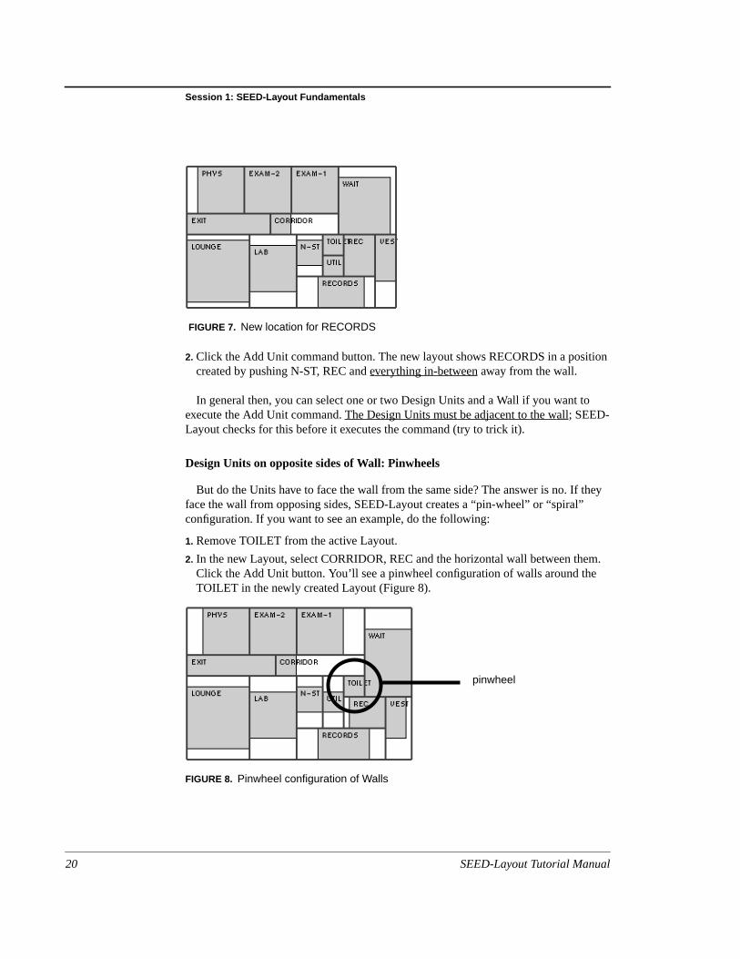
2. Click the Add Unit command button. The new layout shows RECORDS in a positcreated by pushing N-ST, REC andeverything in-between away from the wall.
In general then, you can select one or two Design Units and a Wall if you want toexecute the Add Unit command.The Design Units must be adjacent to the wall; SEED-Layout checks for this before it executes the command (try to trick it).
Design Units on opposite sides of Wall: Pinwheels
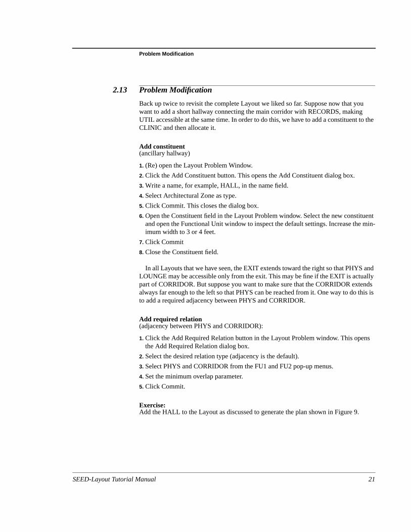
But do the Units have to face the wall from the same side? The answer is no. If tface the wall from opposing sides, SEED-Layout creates a “pin-wheel” or “spiral”configuration. If you want to see an example, do the following:
1. Remove TOILET from the active Layout.
2. In the new Layout, select CORRIDOR, REC and the horizontal wall between theClick the Add Unit button. You’ll see a pinwheel configuration of walls around theTOILET in the newly created Layout (Figure 8).
FIGURE 7. New location for RECORDS
FIGURE 8. Pinwheel configuration of Walls
pinwheel
20 SEED-Layout Tutorial Manual
Problem Modification
o the
entmin-
andllyndsis is
ns
2.13 Problem Modification
Back up twice to revisit the complete Layout we liked so far. Suppose now that youwant to add a short hallway connecting the main corridor with RECORDS, makingUTIL accessible at the same time. In order to do this, we have to add a constituent tCLINIC and then allocate it.
Add constituent(ancillary hallway)
1. (Re) open the Layout Problem Window.
2. Click the Add Constituent button. This opens the Add Constituent dialog box.
3. Write a name, for example, HALL, in the name field.
4. Select Architectural Zone as type.
5. Click Commit. This closes the dialog box.
6. Open the Constituent field in the Layout Problem window. Select the new constituand open the Functional Unit window to inspect the default settings. Increase theimum width to 3 or 4 feet.
7. Click Commit
8. Close the Constituent field.
In all Layouts that we have seen, the EXIT extends toward the right so that PHYSLOUNGE may be accessible only from the exit. This may be fine if the EXIT is actuapart of CORRIDOR. But suppose you want to make sure that the CORRIDOR extealways far enough to the left so that PHYS can be reached from it. One way to do thto add a required adjacency between PHYS and CORRIDOR.
Add required relation(adjacency between PHYS and CORRIDOR):
1. Click the Add Required Relation button in the Layout Problem window. This opethe Add Required Relation dialog box.
2. Select the desired relation type (adjacency is the default).
3. Select PHYS and CORRIDOR from the FU1 and FU2 pop-up menus.
4. Set the minimum overlap parameter.
5. Click Commit.
Exercise:Add the HALL to the Layout as discussed to generate the plan shown in Figure 9.
SEED-Layout Tutorial Manual 21

Session 1: SEED-Layout Fundamentals
ed-toeence by it the
2.14 Extended Exercise
Load the problem RanchFloor, which contains a “bare-bones” program for a raisranch suburban residence. Add relational constraints if you like. Use this problem generate a raised ranch plan, either the simplest solution shown in Figure 10 or thincreasingly more elaborate solutions shown in Figure 11 and Figure 12; the differis that for the latter problems, you will have to extend the Layout Problem as givenadding a second bathroom, hall, even closets. The last plan is interesting becausedemonstrates that for tight layouts, pinwheel configurations are indispensable (seesecondary hall in the back of the plan).
FIGURE 9. CLINIC with ancillary hall
FIGURE 10. Minimal raised ranch plan
22 SEED-Layout Tutorial Manual

Extended Exercise
FIGURE 11. Raised ranch with second bathroom
FIGURE 12. Four-bedroom raised ranch
SEED-Layout Tutorial Manual 23

Session 1: SEED-Layout Fundamentals
24 SEED-Layout Tutorial Manual
sh toand
dow:
3. Session 2: Hierarchical LayoutGeneration
Prerequisites: successful completion of session 1.
Note: The HOUSE problem does not work properly in this PC version!
3.1 Overview
This chapter introduces the major devices SEED-Layouts offers designers who wicreate layouts with specific organizational characteristics. The following concepts commands are introduced in this chapter:
• Constituent hierarchies
• Problems and subproblems
• Layouts and sublayouts
• SEED-Layout outputs
3.2 Constituent Hierarchies
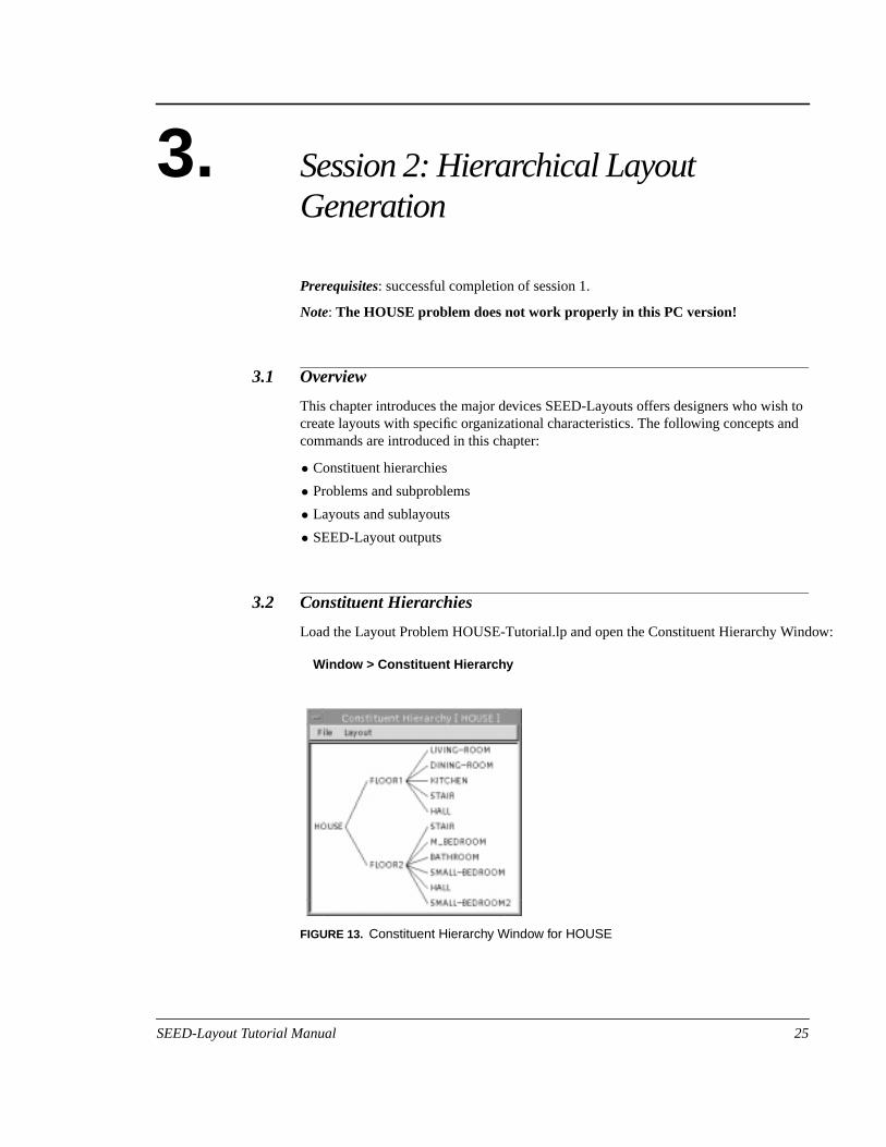
Load the Layout Problem HOUSE-Tutorial.lp and open the Constituent Hierarchy Win
Window > Constituent Hierarchy
FIGURE 13. Constituent Hierarchy Window for HOUSE
SEED-Layout Tutorial Manual 25
Session 2: Hierarchical Layout Generation
-o
thethese
nitsmentbe
uent
ou
sr.
the
and
ntour
You see a tree diagram depicting Functional Units on two floors. Note that SEEDLayout considers all nodes in the diagram Functional Units: the entire house, its twfloors, and the rooms on each floor. We say that the two floors are constituents of house, and the rooms on each floor are constituents of that floor. Taken together, constituent relations form what we call aconstituent hierarchy.
Constituent Hierarchy A constituent hierarchy consists of Functional Units that contain other Functional Uas constituents. SEED-Layout interprets the constituent relations as spatial containrelations: When a Functional Unit is allocated by a Design Unit, its constituents willallocated strictlyinside this Design Unit.
Requirements are associated with each Functional Unit at each level in a constithierarchy. You may inspect these requirements for each Functional Unit from theConstituent Hierarchy Window:
Inspect the requirements of a Functional Unit from the Constituent HierarchyWindow1. Select the Functional Unit in the Constituent Hierarchy Window;
2. Click the right mouse button; this brings up a dialog box;
3. Select the Open command. This brings up a Functional Unit Window that allows yto inspect the requirements associated with the selected Functional Unit.
Exercise:Inspect the min. area requirement for a floor and the min. area requirements of itsFunctional Unit constituents; you will see that the min. area of the floor is at least alarge as the sum of the min. area requirements for the individual rooms on the floo
3.3 Sublayout Problems
Observe that the first constituent allocated in the current Layout is FLOOR1. ClickNext Child button in the Design Window. This allocates the second flooron top of thefirst floor.
This is to say, SEED-Layout knows that floors cannot be placed next to each otherautomatically assumes that they are placed on top of each other. How does it knowwhich floor is on top of which floor?
Open the Functional Unit Window for one of the floors, either from the ConstitueHierarchy Window or from the Layout Problem Window as explained in session 1. Ywill notice that the Floor Above or Floor Below field indicates which floor is above obelow the floor you are looking at.
26 SEED-Layout Tutorial Manual
The Problem Hierarchy
notce a
of
e
sa
,
y
at
, a
ed.
ign
Note that the Add Design Unit command featured prominently in Session 1 doeswork for floors or storeys because they cannot be placed next to each other. To plafloor constituent, youmust use the Next Child button in the Design Window.
Let’s now try to allocate the Functional Units on the first floor:
Expand a Floor/Storey1. Move cursor over stacked floors.
2. Click the right mouse button. This brings up a pop-up menu giving you the optionexpanding FLOOR-1 or FLOOR-2.
3. Select Expand FLOOR-1. The display in the Design Window changes to show thfirst floor with its first constituent, LIVING-ROOM, allocated in it.
Selecting a Design Unit in order to allocate constituent Functional Units inside itboundary is calledexpandingthe Design Unit. It does not matter if we are expandingDesign Unit associated with a floor or any other type of Functional Unit. The onlyprecondition is that the Functional Unit has constituent Functional Units; otherwisethere would be nothing to place. This will become clearer later on in this session.
Inspect the new Layout Problem in the Layout Problem and Constituent HierarchWindows. The Layout Problem described in these windows is considered asubproblemof the overall Layout Problem by SEED-Layout. This subproblem is now theactiveLayout Problem.
Look at both Context and Constituents of the active Layout Problem. Observe ththis subproblem has the same kinds of parts as the overall problem, a Context andConstituents; this is always true in SEED-Layout: no matter at which level you areLayout Problem always has a Context and Constituents.
You do not have to specify the Context for subproblems: SEED-Layout finds itautomatically by looking at the coordinates of the Design Unit that is being expand
Exercise:Allocate the rest of the Functional Units on the first floor. Try to find a layout thatsatisfies all requirements. Refer to Figure 14a to see a Layout that will work.
3.4 The Problem Hierarchy
Make sure that the active Layout Problem is the FLOOR-1 subproblem. In the DesWindow, the
Problem > Goto Superproblem
SEED-Layout Tutorial Manual 27

Session 2: Hierarchical Layout Generation
s the andrk
st
m
andat is
as
r
command gets you back to the higher-level problem of which the current LayoutProblem is a subproblem. Observe that the Design Window simultaneously displaylast active Layout in the superproblem. This Layout Problem is now the active onethe Layout in the Design Window is now the active Layout. You could continue to woon this Layout if there were more Functional Unitsat this level to be allocated. In short,the Goto Superproblem commandreactivates a Layout Problem and a Layout.
Expand the second floor as you did with the first floor: move the cursor over thestacked floors, press the right button and select Expand FLOOR-2. SEED-Layoutcreates a new subproblemat thesamelevel as the FLOOR-1 problem. This subproblemis now the active Layout Problem. Try to generate a layout compatible with your firfloor layout (see Figure 14b).
Go back to the superproblem; observe how the active Layout and Layout Problechange again. The
Problem > Goto subproblem
command, in turn, (re)activates a subproblem. But note that while before this commactivated the FLOOR-1 subproblem, it now activates the FLOOR-2 subproblem. Thto say, the Goto subproblem command always activates the last subproblem of thesuperproblem that has been active. The
Problem > Goto last problem
command activates a subproblem at the same level in the problem hierarchy that wcreated before the current one, in our case, the FLOOR-1 problem. If this lastsubproblem does not exist, the command fails, and SEED-Layout displays an erromessage.
FIGURE 14. House floors, unfinalized
a) Floor 1
b) Floor 2
28 SEED-Layout Tutorial Manual

The Problem Hierarchy
and
chy.een
ms.ute
ght-
enu:
5).
Problem > Goto next problem
also activates a subproblem at the same level in the problem hierarchy. But it wascreatedafter the current one, in our case, the FLOOR-2 problem. Again, this commfails if this next subproblem does not exist.
Problem Hierarchy The super/subproblem relations between Layout Problems form a Problem HierarThere is always one active Layout Problem. Activating Layout Problems that have bactive before is callednavigating the (Layout) Problem Hierarchy.
Note that the Goto commands introduced here do not create new Layout ProbleThey are strictly navigation commands that allow you to revisit or (re)activate LayoProblems that have been created before. Subproblems can be created only with thExpand command.
Open the Layout Problem Window for the FLOOR-2 subproblem. In the upper rihand corner are four navigation buttons that allow you to do the same types ofnavigations that can be done with the Goto commands available in the Problem m
Up arrow: activates superproblem
Down arrow: activates last active subproblem
Right arrow : activates next subproblem
Left arrow : activates last subproblem.
Exercise:Finalize the HOUSE layout.Don’t forget to check the yes box when asked if you wantfinalization through all levels. Navigate again through the Layout Problem hierarchyand inspect the finalized layouts at the super and subproblem levels (see Figure 1
FIGURE 15. Finalized HOUSE floors
SEED-Layout Tutorial Manual 29
Session 2: Hierarchical Layout Generation
thatsnd
of
ckslousetsUSE
nether.ouxt
s ofns.theron a
sk
tible.
the
the
3.5 Vertical Zones
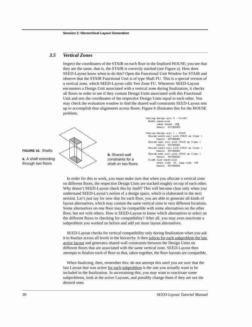
Inspect the coordinates of the STAIR on each floor in the finalized HOUSE; you seethey are the same, that is, the STAIR is correctly stacked (see Figure a). How doeSEED-Layout know when to do this? Open the Functional Unit Window for STAIR aobserve that the STAIR Functional Unit is of type Shaft FU. This is a special versiona vertical zone, which SEED-Layout calls Vert Zone FU. Whenever SEED-Layoutencounters a Design Unit associated with a vertical zone during finalization, it cheall floors in order to see if they contain Design Units associated with this FunctionaUnit and sets the coordinates of the respective Design Units equal to each other. Ymay check the evaluation window to find the shared wall constraints SEED-Layoutup to accomplish thse alignments across floors. Figure b illustrates this for the HOproblem.
In order for this to work, you must make sure that when you allocate a vertical zoon different floors, the respective Design Units are stacked roughly on top of each oWhy doesn’t SEED-Layout check this by itself? This will become clear only when yunderstand SEED-Layout’s notion of a design space, which is elaborated in the nesession. Let’s just say for now that for each floor, you are able to generate all kindlayout alternatives, which may contain the same vertical zone in very different locatioSome alternatives on one floor may be compatible with some alternatives on the ofloor, but not with others. How is SEED-Layout to know which alternatives to selectthe different floors in checking for compatibility? After all, you may even reactivatesubproblem you worked on before and add yet more layout alternatives.
SEED-Layout checks for vertical compatibility only during finalization when you ait to finalize across all levels in the hierarchy. It thenselectsfor eachsubproblemthelastactive layout and generates shared wall constraints between the Design Units ondifferent floors that are associated with the same vertical zone. SEED-Layout thenattempts to finalize each of floor so that, taken together, the floor layouts are compa
When finalizing, then, remember this: do not attempt this until you are sure that last Layout that was activefor each subproblem is the one you actually want to beincluded in the finalization. In ascertaining this, you may want to reactivate somesubproblems, look at the active Layouts, and possibly change them if they are notdesired ones.
FIGURE 16. Shafts
a. A shaft extendingthrough two floors
b. Shared wallconstraints for ashaft on two floors
30 SEED-Layout Tutorial Manual
More Functional Unit Types
lU, a
f,s, inlyo that
meicklyn
redany
3.6 More Functional Unit Types
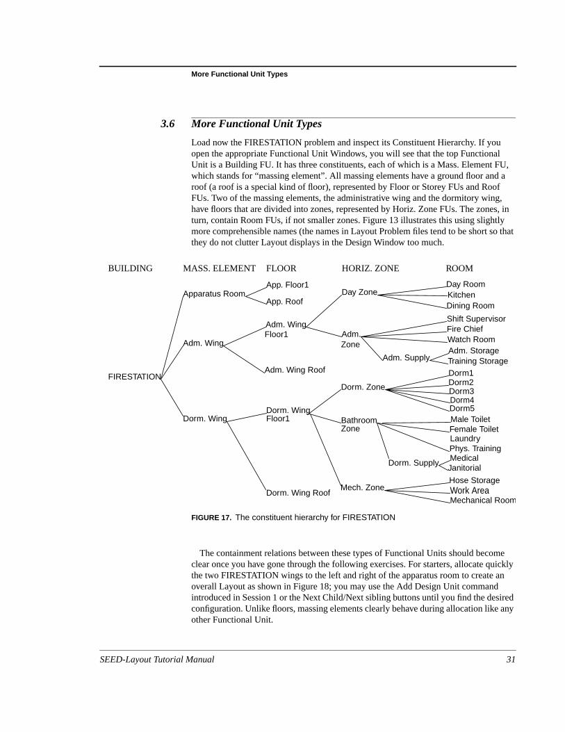
Load now the FIRESTATION problem and inspect its Constituent Hierarchy. If youopen the appropriate Functional Unit Windows, you will see that the top FunctionaUnit is a Building FU. It has three constituents, each of which is a Mass. Element Fwhich stands for “massing element”. All massing elements have a ground floor androof (a roof is a special kind of floor), represented by Floor or Storey FUs and RooFUs. Two of the massing elements, the administrative wing and the dormitory winghave floors that are divided into zones, represented by Horiz. Zone FUs. The zoneturn, contain Room FUs, if not smaller zones. Figure 13 illustrates this using slightmore comprehensible names (the names in Layout Problem files tend to be short sthey do not clutter Layout displays in the Design Window too much.
The containment relations between these types of Functional Units should becoclear once you have gone through the following exercises. For starters, allocate quthe two FIRESTATION wings to the left and right of the apparatus room to create aoverall Layout as shown in Figure 18; you may use the Add Design Unit commandintroduced in Session 1 or the Next Child/Next sibling buttons until you find the desiconfiguration. Unlike floors, massing elements clearly behave during allocation likeother Functional Unit.
BUILDING MASS. ELEMENT FLOOR HORIZ. ZONE ROOM
FIRESTATION
Apparatus Room
Adm. Wing
Dorm. Wing
App. Roof
App. Floor1
Adm. Wing
Adm. Wing Roof
Dorm. Wing
Dorm. Wing Roof
Day Zone
Adm.
Day RoomKitchenDining Room
Shift SupervisorFire Chief
Adm. Supply
Watch Room
Dorm1Dorm2Dorm3Dorm4Dorm5Male ToiletFemale ToiletLaundry
Dorm. Supply
Phys. Training
Hose StorageWork AreaMechanical Room
Mech. Zone
Bathroom
Dorm. Zone
Zone
Zone
Floor1
Floor1
Adm. StorageTraining Storage
MedicalJanitorial
FIGURE 17. The constituent hierarchy for FIRESTATION
SEED-Layout Tutorial Manual 31

Session 2: Hierarchical Layout Generation
op
ow
rs.of.
vermand,
tal
nesh the
ent
e 19.
givenll2,
Let’s now layout the administrative wing. Note that this is not a floor stacked on tor below another floor, but an element laid out horizontally with other elements.Expansion is a little different in this case:
Expand a Design Unit that is not a Floor:1. Select the Design Unit, in our case, adm_wing.
2. Click the Expand button in the command bar of the Design Window. You will see hthe display changes to show the first floor of the adm. wing allocated.
Note that like the HOUSE, the constituents of the administrative wing are all flooIts first floor has been placed. You may click the Next child button to place also the roIf we want to develop the first floor in the administrative wing further, we face thesituation known from the HOUSE: in order to expand a floor, we move the cursor othe stacked floors, press the right mouse button and select the desired expand comin our case, Expand admw_1s.
In the new Layout Problem, the two Functional Units to be allocated are horizonzones, and the first of these, the day zone, has been allocated. Allocate theadministrative zone admZ_1s below the day zone. You will notice that horizontal zocan be allocated like rooms or massing elements. Note also that by stepping througsubproblems level-by-level and allocating Functional Units at each level, we arerealizing a specific organizational scheme that is expressed by the overall constituhierarchy of FIRESTATION.
Try now to complete the FIRESTATION layout by doing the following exercises,which require more and more independence and sophistication on your part.
Exercises:1. Expand the day zone to create a layout of its Functional Units as shown in Figur
2. Reactivate the superproblem and expand the administrative zone. Place the fourconstituents first, then create two new Functional Units constituents, Hall and Hato create a good circulation system as shown in Figure 19.
FIGURE 18. Top-level layout of FIRESTATION
32 SEED-Layout Tutorial Manual

Functional Unit Types: Summary
pande
orss,
youtessd, to
ntof
Unit;
ed
if
not
3. If you mastered the previous exercises, reactivate the top Layout Problem and exthe dorm wing. In order to accomplish this, you need to apply everything you havlearned so far: how to allocate Functional Units including floors, how to expand floand other types of Functional Units, how to navigate through problem hierarchieand how to add Functional Unit constituents.
4. When you are done, finalize the entire FIRESTATION.
Inspect the finalized layouts at all levels and see how they fit together. SEED-Latries to fill holes on floors and to make stacked floors fit into a rectangular box (unlyou explicitly modified the floor coordinates of the respective Design Unit or createboundary constraints in the associated Functional Unit to prevent this, for examplecreate a terraced mass). But SEED-Layout doesnot try to press massing elements intoan overall box; it actually tries to find the minimal footprint for each massing eleme(again, you may counteract this by explicitly overwriting the Design Unit coordinatesa massing element or by setting boundary constraints in the associated Functionalsee, for example, the boundary constraint for the dorm. wing).
3.7 Functional Unit Types: Summary
For easy reference, we summarize below what you observed or may have guessabout the constituent relations between the different types of Functional Units. TheFundamental Concepts manual gives more details. It specifically shows how veryintricate massing/zoning relations can be established with these types of FUs eventhey can be allocated only by rectangular Design Units.
Building FU A building is typically the top Functional Unit in a complex, multi-floor LayoutProblem. Its constituents are either all massing elements; all floors (if it is to beconsidered a single ‘box’); or only room and horizontal zone constituents (if you areinterested in other floors).
FIGURE 19. Sublayouts in the administrative wing of FIRESTATION
Day zone Administrative zone
SEED-Layout Tutorial Manual 33

Session 2: Hierarchical Layout Generation
that
nal
of
an
nre 20floors, or
en to
s. It
s.
Massing Element FU A massing element is a building constituent with no other elements above or below;is, it is allocated directly on the site. It must be either a top Functional Unit or theconstituent of a building; that is, it cannot be contained in any other type of FunctioUnit. Its constituents are either all floors or only rooms and horizontal zones. Usemassing elements when you knows before-hand that the planned building consistsseparate components or wings. A good example is the firestation prototype with itscentral apparatus room and two wings at opposite ends, each of which constitutesindependent massing element in the SEED-Layout sense.
Floor/storey FU A floor or storey can only be the constituent of a massing element or a building.Different massing elements may have different numbers of floors. Use the elevatioattribute to indicate which floors are continuous across massing elements (see Figufor the containment relations between buildings, massing elements and floors). A may contain among its constituents only vertical zones like shafts, horizontal zonerooms.
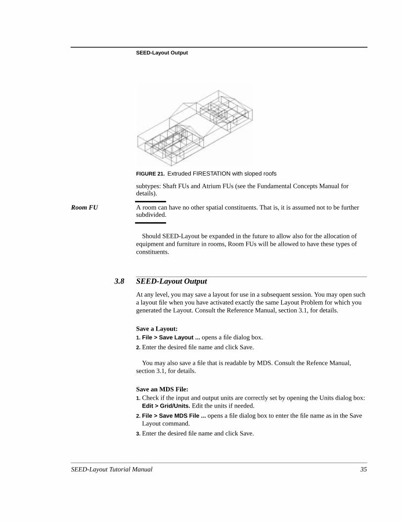
Roof FU A roof is a special floor without constituents. It has two subtypes: Flat Roof FU andSloped Roof FU. SEED-Layout does not do anything with roofs; it only uses them whit creates a 3-dimensional extrusion of a multi-storey Layout, for example, in orderdisplay it (see Figure 21for an example); it looks at the roof type to find an initialgeometric form for a roof.
Horizontal Zone FU A horizontal zone may contain vertical zones like shafts, horizontal zones, or roommay not contain floors, massing elements, or buildings.
Vertical Zone FU A vertical zone may be the constituent of a floor or horizontal zone, provided thehorizontal zone it the constituent of a floor. It is expected to be on at least two floorThe floors containing the same vertical zone must form a sequence of floors notinterrupted by floors that do not contain the vertical zone. Vertical zones have two
massing element
floor/
building
FIGURE 20. Relations between Building FUs, Mass. Element FUs and Floor/Storey FUs
storey
34 SEED-Layout Tutorial Manual
SEED-Layout Output
her
ff
suchou
box:
ve
subtypes: Shaft FUs and Atrium FUs (see the Fundamental Concepts Manual fordetails).
Room FU A room can have no other spatial constituents. That is, it is assumed not to be furtsubdivided.
Should SEED-Layout be expanded in the future to allow also for the allocation oequipment and furniture in rooms, Room FUs will be allowed to have these types oconstituents.
3.8 SEED-Layout Output
At any level, you may save a layout for use in a subsequent session. You may opena layout file when you have activated exactly the same Layout Problem for which ygenerated the Layout. Consult the Reference Manual, section 3.1, for details.
Save a Layout:1. File > Save Layout ... opens a file dialog box.
2. Enter the desired file name and click Save.
You may also save a file that is readable by MDS. Consult the Refence Manual,section 3.1, for details.
Save an MDS File:1. Check if the input and output units are correctly set by opening the Units dialog
Edit > Grid/Units. Edit the units if needed.
2. File > Save MDS File ... opens a file dialog box to enter the file name as in the SaLayout command.
3. Enter the desired file name and click Save.
FIGURE 21. Extruded FIRESTATION with sloped roofs
SEED-Layout Tutorial Manual 35
Session 2: Hierarchical Layout Generation
was will
me
cann
ou
Note that an MDS filesaves those and only those Design Units that have not beenexpanded; that is, they contain no sublayouts. For example, a floor will be saved if itnever expanded; if it was expanded, but only down to the level of zones, the zonesbe saved, but not the floor; if some zones were expanded and others were not, sozones will be saved, while others will be replaced by the Design Units inside.It is yourresponsibility to make sure that all Design Units are expanded to a level where theyrepresent properly named MDS modules.
You may save an .html file that describes the active Layout Problem in a form thatbe easily read by HTML browsers and printed. Consult the Refence Manual, sectio3.6, for details.
Save Problem Document:1. Check if the input units are correctly set by opening the Units dialog box:Edit > Grid/
Units. Edit the units if needed.
1. Problem > Save Document File... opens a file dialog box.
2. Enter or select the desired file name. Do NOT enter the .html extension.
3. Click Save.
3.9 Extended Exercise
Open the San Antonio Training Building problem. Try to lay out as many parts as yfeel inclined to and create an MDS file.
36 SEED-Layout Tutorial Manual
n
-
show
4. Session 3: The SEED-Layout DesignSpace
Prerequisites: successful completion of Session 2.
Approximate time to complete:
4.1 Overview
This chapter introduces advanced concepts centered around the notion of “desigspace” as it is understood in the SEED-Layout context. Once you mastered thismaterial, you may sigh with relief: this is as complicated as it will ever get in SEEDLayout. The following concepts are the focus of the session:
• SEED-Layout problems and subproblems/spaces
• Alternative subproblems/spaces
• Variant problems/spaces
• SEED-Layout design space
• Navigation in the design space
The goal of present session is to make you understand the above concepts andyou how to “navigate” through the SEED-Layout Design space.
4.2 A Simple Design Space
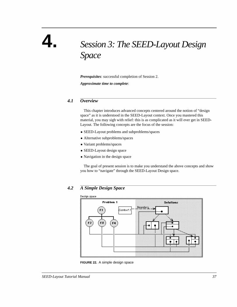
FIGURE 22. A simple design space
SEED-Layout Tutorial Manual 37

Session 3: The SEED-Layout Design Space
ingltiplenly a
childurUnitses
ons
ildotherot
a
al)
isem
onsaking
on
on. Lay-
Load the FIRESTATION Layout Problem known to you from Session 2. We are goto retrace some of the exercises from Session 2, but pay more attention to the murelations between elements established in this process. In fact, we will introduce ofew new commands in the present session; the focus is on arriving at a deeperunderstanding of the underlying concepts.
Start by allocating again the three top-level massing elements. Inspect the parent/relations between the Layouts in the Layout Tree Window. In addition, clarify in yoown mind the relations between the Design Units in the Layouts and the Functionalconstituents of the Layout Problem that are associated with the Design Units. Therelations are depicted abstractly in Figure 22. To make this and the following figureeasier to understand, we drew Functional Units that occur in more than one spaceindividually for each space; a grey link between two elements indicates that the twunits are in fact the same. Solid and dashed black links, in contrast, indicate relatiobetween distinct elements. Note the one-to-many relations between parent and chlayouts, on the one hand, and between Functional Units and Design Units, on the hand. All of these relations are explicitly managed by SEED-Layout, and you do nhave to remember them.
We call the Layout Problem and the Layout solutions generated for this problemdesign space. Every design space contains at least one Layout and ‘knows’ the lastactive Layout.
4.3 Subproblems and Subspaces
Expand the administrative wing. This allocates the first storey in this wing. (Optionallocate the adm_wing_roof on top of the first storey.
Expand the first floor in the administrative wing. This allocates the day zone in thwing. Place the administrative zone beneath the day zone. Open the Layout ProblManager:
Window > Layout Problem Manager.
This is a window we have not seen in prior sessions. It depicts explicitly the relatibetween super- and subproblems and allows you to navigate between problems mlarger steps than are possible with the Goto commands and navigation buttonsintroduced in Session 2:
Activate a Layout Problem in the Layout Problem Manager:1. Select a problem in the Layout Problem Manager by clicking the left mouse button
it.
2. Click the right mouse button to open a pop-up menu and select the Activate optiThis changes the currently active Layout Problem and reactivates the last activeout in the associated design space.
38 SEED-Layout Tutorial Manual
Subproblems and Subspaces
esignne
or.
it in
eof the notct It is
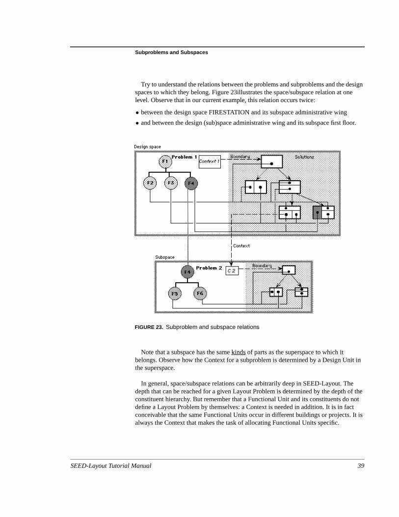
Try to understand the relations between the problems and subproblems and the dspaces to which they belong. Figure 23illustrates the space/subspace relation at olevel. Observe that in our current example, this relation occurs twice:
• between the design space FIRESTATION and its subspace administrative wing
• and between the design (sub)space administrative wing and its subspace first flo
Note that a subspace has the samekinds of parts as the superspace to which itbelongs. Observe how the Context for a subproblem is determined by a Design Unthe superspace.
In general, space/subspace relations can be arbitrarily deep in SEED-Layout. Thdepth that can be reached for a given Layout Problem is determined by the depth constituent hierarchy. But remember that a Functional Unit and its constituents dodefine a Layout Problem by themselves: a Context is needed in addition. It is in faconceivable that the same Functional Units occur in different buildings or projects.always the Context that makes the task of allocating Functional Units specific.
FIGURE 23. Subproblem and subspace relations
SEED-Layout Tutorial Manual 39

Session 3: The SEED-Layout Design Space
the
y
lled
4.4 Alternative Subproblems and Subspaces
Revisit the first floor in the administrative wing. Expand the day zone and allocate constituents in it.
Goto the superproblem first floor. Create an alternative layout of the two zones bclicking the Next Sibling button. Expand the day zone again and allocate theconstituents in it.
Inspect the Layout Problem Manager. Why does it show two Layout Problems cadayZ_1? Visit and revisit the two expanded layouts of dayZ_1 (make sure thesuperlayout view is on). Clearly, each allocates the same constituents,but the Contextsare different (see also Figure 24).
FIGURE 24. Alternative subproblems and subspaces
40 SEED-Layout Tutorial Manual
Variant Layout Problems and Design Spaces
oponeated
nd
ut
een
, the
pish
m ad in
the
how
e
Recall from Session 1 that a Layout Problem has two basic parts: a Context, a tfunctional Unit with its constituents and associated requirements. If we change anyof these parts, we create a new Layout Problem. The Layout Problems that we creby expanding the day zone in two different layouts share the top Functional Unit aconstituents, but each has a unique Context. The two Layout Problems and theassociated design spaces are therefore different.
We call themalternative subproblems and subspaces because they are at the samelevel in the problem hierarchy, but indicate alternative solutions to the overall LayoProblem.
4.5 Variant Layout Problems and Design Spaces
Revisit the first floor in the administrative wing. Open the Constituent HierarchyWindow and inspect its contents. Reopen the Layout Problem Manager (if it has bclosed).
Select the day zone in the active Layout and click the Disaggregate button in thecommand bar of the Design Window. Observe what happens in the Design WindowConstituent Hierarchy Window, and the Layout Problem Manager.
We changed the constituents of the Layout Problem while keeping the Contextconstant. This is the opposite effect of creating an alternative subproblem. Wenevertheless created a different Layout Problem because the constituents of the toFunctional Unit, the first floor in the administrative wing, have changed. To distinguthis case from the case of alternative subproblems, we call the new Layout Problevariantof the old one. Figure 25 depicts the relations between all elements discussethis session.
SEED-Layout Design SpaceWe call all problems, subproblems, alternative problems, variant problems andlayouts generated in each of the associated design spaces the (overall)SEED-Layoutdesign space.
Finalize through all levels. Navigate through the problem hierarchy and observe the sublayouts again fit into their superlayouts.
Picture in your mind what SEED-Layout had to do when it finalized the overallLayout: It not only had to link all super- and sublayouts together, it also had to maksure that at each sublevel, it used the last active design space variant.
SEED-Layout Tutorial Manual 41

Session 3: The SEED-Layout Design Space
FIGURE 25. The full SEED-Layout design space
42 SEED-Layout Tutorial Manual
Extended Exercise
.nnits
nges
ratet.
Exercise:Revisit each subspace whose active Layout was finalized and reactivate its parentRevisit the first floor variant design space, which contains the disaggregated DesigUnits from the former day zone. Select the four walls that surround these Design Uand click the Aggregate button in the command bar.
This opens a dialog box which prompts you for a Functional Unit name. Key-in aname and click OK.
Observe again in the open windows what happens and try to understand the chathat you see in light of what you have learned about the disaggregate command.
4.6 Extended Exercise
Open a Layout Problem describing the San Antonio training building and try to genea complete layout of all massing elements and floors inside each massing elemen
SEED-Layout Tutorial Manual 43

Session 3: The SEED-Layout Design Space
44 SEED-Layout Tutorial Manual