security system user guide - burglar alarms & wireless burglar
TRANSCRIPT
Security System
User Guide
Page ii
Contents 1. Introduction .................................................... 1
Controls and Displays.......................................... 3 Displays......................................................... 3 Controls:........................................................ 4
2. Everyday Operation......................................... 5 Access to the System .......................................... 5
Entering and Leaving the Protected Area ............ 5 Setting.............................................................. 6
Full Set.......................................................... 6 Quick Set ....................................................... 8 Part Set ......................................................... 8 If the System Will Not Set ................................ 9 Setting With a Remote control......................... 10
Unsetting ........................................................ 11 Unsetting With a Remote control ..................... 11
3. Alarms........................................................... 12 Types of Alarm................................................. 12 Silencing an Alarm............................................ 13
4. Alerts (or Why is it Beeping?) ....................... 14 5. Administration............................................... 15
Entering the Menu ............................................ 15 Omit Zones...................................................... 16 Users.............................................................. 16
Editing Existing Users .................................... 16 Adding Users ................................................ 22 Deleting Users .............................................. 23
View Log ......................................................... 24 Test................................................................ 24 System Configuration........................................ 25
Facilities On/Off ............................................ 26 Set Date and Time ........................................ 26 Loudspeaker Volume...................................... 27 Speech Phone Book ....................................... 27
List of Menu Options ......................................... 29
Page 1
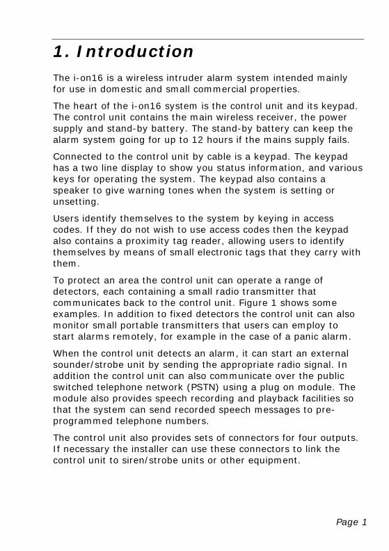
1. Introduction The i-on16 is a wireless intruder alarm system intended mainly for use in domestic and small commercial properties.
The heart of the i-on16 system is the control unit and its keypad. The control unit contains the main wireless receiver, the power supply and stand-by battery. The stand-by battery can keep the alarm system going for up to 12 hours if the mains supply fails.
Connected to the control unit by cable is a keypad. The keypad has a two line display to show you status information, and various keys for operating the system. The keypad also contains a speaker to give warning tones when the system is setting or unsetting.
Users identify themselves to the system by keying in access codes. If they do not wish to use access codes then the keypad also contains a proximity tag reader, allowing users to identify themselves by means of small electronic tags that they carry with them.
To protect an area the control unit can operate a range of detectors, each containing a small radio transmitter that communicates back to the control unit. Figure 1 shows some examples. In addition to fixed detectors the control unit can also monitor small portable transmitters that users can employ to start alarms remotely, for example in the case of a panic alarm.
When the control unit detects an alarm, it can start an external sounder/strobe unit by sending the appropriate radio signal. In addition the control unit can also communicate over the public switched telephone network (PSTN) using a plug on module. The module also provides speech recording and playback facilities so that the system can send recorded speech messages to pre-programmed telephone numbers.
The control unit also provides sets of connectors for four outputs. If necessary the installer can use these connectors to link the control unit to siren/strobe units or other equipment.
Introduction
Page 2
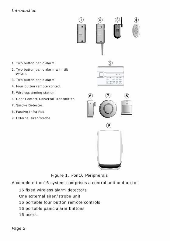
1. Two button panic alarm.
2. Two button panic alarm with tilt switch.
3. Two button panic alarm
4. Four button remote control.
5. Wireless arming station.
6. Door Contact/Universal Transmitter.
7. Smoke Detector.
8. Passive Infra Red.
9. External siren/strobe.
A
B
A
B
C
D
1
4 ghi
7 pqrs
* 0 #
2 abc
5 jkl
3 def
6 mno
8 tuv 9 wxyz
Figure 1. i-on16 Peripherals
A complete i-on16 system comprises a control unit and up to:
16 fixed wireless alarm detectors
One external siren/strobe unit
16 portable four button remote controls
16 portable panic alarm buttons
16 users.
Introduction
Page 3
This rest of this guide shows the simple procedures required to operate and administer the system. For information on installing the i-on16 please read i-on16 Installation and Programming Guide. Each of the radio peripherals also have their own guides.
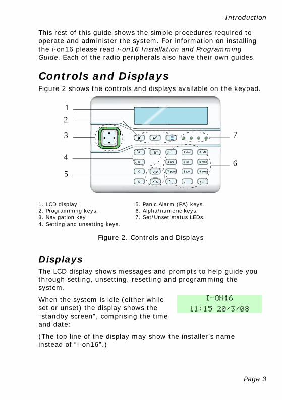
Controls and Displays Figure 2 shows the controls and displays available on the keypad.
A
B
C
D
1
4 ghi
7 pqrs
* 0 #
2 abc
5 jkl
3 def
6 mno
8 tuv 9 wxyz
2
3
4
5
7
6
1
1. LCD display . 5. Panic Alarm (PA) keys. 2. Programming keys. 6. Alpha/numeric keys. 3. Navigation key 7. Set/Unset status LEDs. 4. Setting and unsetting keys.
Figure 2. Controls and Displays
Displays The LCD display shows messages and prompts to help guide you through setting, unsetting, resetting and programming the system.
When the system is idle (either while set or unset) the display shows the “standby screen”, comprising the time and date:
I-ON16
11:15 20/3/08
(The top line of the display may show the installer’s name instead of “i-on16”.)
Introduction
Page 4
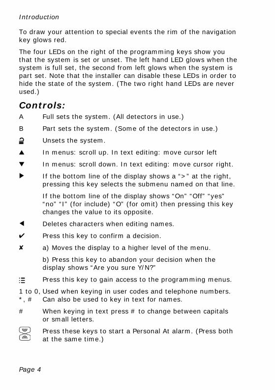
To draw your attention to special events the rim of the navigation key glows red.
The four LEDs on the right of the programming keys show you that the system is set or unset. The left hand LED glows when the system is full set, the second from left glows when the system is part set. Note that the installer can disable these LEDs in order to hide the state of the system. (The two right hand LEDs are never used.)
Controls: A Full sets the system. (All detectors in use.)
B Part sets the system. (Some of the detectors in use.)
Unsets the system.
u In menus: scroll up. In text editing: move cursor left
n In menus: scroll down. In text editing: move cursor right.
> If the bottom line of the display shows a “>” at the right, pressing this key selects the submenu named on that line.
If the bottom line of the display shows “On” “Off” “yes” “no” “I” (for include) “O” (for omit) then pressing this key changes the value to its opposite.
< Deletes characters when editing names.
Y Press this key to confirm a decision.
X a) Moves the display to a higher level of the menu.
b) Press this key to abandon your decision when the display shows “Are you sure Y/N?”
Press this key to gain access to the programming menus.
1 to 0, *, #
Used when keying in user codes and telephone numbers. Can also be used to key in text for names.
# When keying in text press # to change between capitals or small letters.
Press these keys to start a Personal At alarm. (Press both at the same time.)
Page 5
2. Everyday Operation Everyday operation involves setting and unsetting the alarm system and occasionally dealing with alarms. If you need to know how to set up new users, or change the way the system operates then please read the “Administration” section.
Access to the System To operate the system a user must identify themselves, either by entering an access code on the keypad or by presenting a proximity tag to the front of the keypad.
Access code and tag act as unique identifiers for each user, and may be used interchangeably at any time.
When delivered from the factory the control unit recognises just one user, and this user has Administrator privileges (see page 15). This user’s default access code is “1234”, and they do not have any tag or other device registered to their account.
Cooper Security Limited recommend that you change the default access code as soon as possible (see page 16).
The installer has a separate access code which they cannot use to set or unset the alarm system. Neither can they use that code to change details of other users registered to the system. Similarly, the Administrator code has no access to any installer programming menus.
Entering and Leaving the Protected Area In many alarm systems the keypad is inside the protected area. To make sure that you can get to the keypad when the system is set without starting an alarm the installer programs the control unit to pause for a few moment if it detects activity on specific entry/exit routes. The installer chooses the length of the pause to enable you to get to the keypad if you are entering, or leave the protected area if you are setting the system. During the pause the keypad will give a warning tone. When you hear the warning tone do not stray off the entry/exit route chosen by the installer or you will start an alarm.
Everyday Operation
Page 6
Setting Note: Whenever you set the system you should first make sure that all doors and windows are secure.
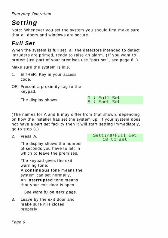
Full Set When the system is full set, all the detectors intended to detect intruders are primed, ready to raise an alarm. (If you want to protect just part of your premises use “part set”, see page 8 .)
Make sure the system is idle.
1. EITHER: Key in your access code.
OR Present a proximity tag to the keypad.
The display shows:
A : Full Set
B : Part Set
(The names for A and B may differ from that shown, depending on how the installer has set the system up. If your system does not have a part set facility then it will start setting immediately, go to step 3.)
2. Press A.
The display shows the number of seconds you have to left in which to leave the premises.
The keypad gives the exit warning tone: A continuous tone means the system can set normally. An interrupted tone means that your exit door is open.
See Note b) on next page.
3. Leave by the exit door and make sure it is closed properly.
Setting:Full Set 10 to set
Everyday Operation
Page 7
At the end of the exit time the exit warning tone stops and you should hear a double “beep” confirmation tone to let you know that the system is set.
The display shows the message "System Set" for a few seconds, followed by the standby screen. The LED marked “A” glows to show that the system is full set.
System Set
Notes: a) If you decide you want to stop setting then press . b) Your system may be programmed to set silently. If so, there will be no exit warning tone as the system sets. c) If your system is full set you cannot go directly to part set. You must unset the system first. d) If your system is part set, then you cannot go directly to full set. You must unset the system first.
Everyday Operation
Page 8
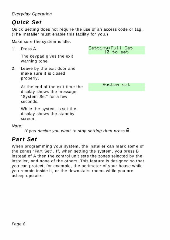
Quick Set Quick Setting does not require the use of an access code or tag. (The Installer must enable this facility for you.)
Make sure the system is idle.
1. Press A.
The keypad gives the exit warning tone.
Setting:Full Set
10 to set
2. Leave by the exit door and make sure it is closed properly.
At the end of the exit time the display shows the message "System Set" for a few seconds.
While the system is set the display shows the standby screen.
System set
Note: If you decide you want to stop setting then press .
Part Set When programming your system, the installer can mark some of the zones “Part Set”. If, when setting the system, you press B instead of A then the control unit sets the zones selected by the installer, and none of the others. This feature is designed so that you can protect, for example, the perimeter of your house while you remain inside it, or the downstairs rooms while you are asleep upstairs.
Everyday Operation
Page 9
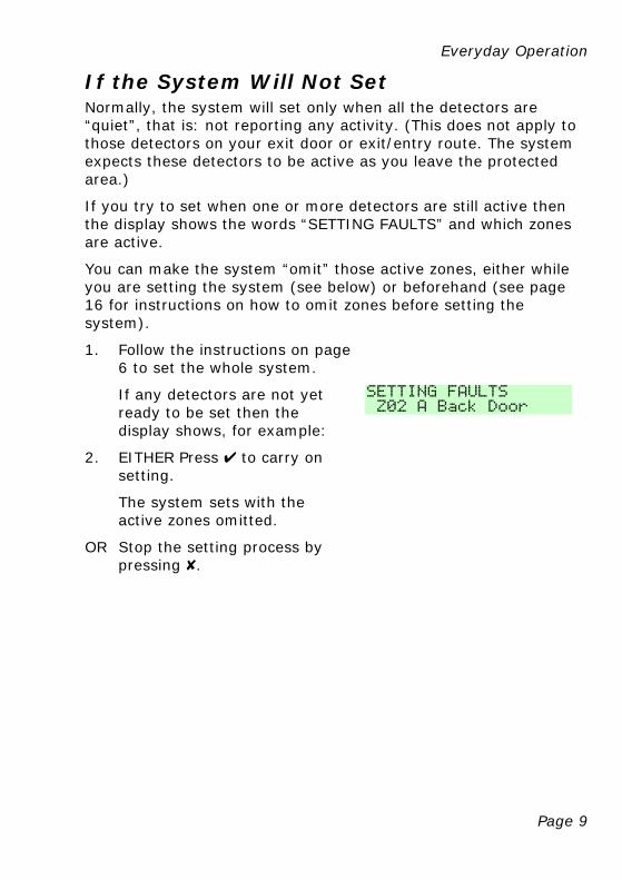
If the System Will Not Set Normally, the system will set only when all the detectors are “quiet”, that is: not reporting any activity. (This does not apply to those detectors on your exit door or exit/entry route. The system expects these detectors to be active as you leave the protected area.)
If you try to set when one or more detectors are still active then the display shows the words “SETTING FAULTS” and which zones are active.
You can make the system “omit” those active zones, either while you are setting the system (see below) or beforehand (see page 16 for instructions on how to omit zones before setting the system).
1. Follow the instructions on page 6 to set the whole system.
If any detectors are not yet ready to be set then the display shows, for example:
SETTING FAULTS
Z02 A Back Door
2. EITHER Press Y to carry on setting.
The system sets with the active zones omitted.
OR Stop the setting process by pressing X.
Everyday Operation
Page 10
Setting With a Remote control Note: You must program the control unit to recognise ("learn") a
remote control, see page 23.
Secure all your windows and doors.
Make sure the system is idle, and that you can hear the warning tones from the keypad.
1. On the remote control, either press A (full set) or B (part set), see page 20.
The keypad sounds the exit warning tone.
2. Leave by the exit door and make sure it is closed properly (if you have not already done so).
At the end of the exit time the warning tone stops you should hear a double “beep” confirmation tone. The display shows the message "System Set" for a few seconds. The installer may also have programmed your external sounder/strobe to flash briefly.
While the system is set the display shows the standby screen and the left hand LED glows.
If The System Will Not Set If one of the detectors is still active when you try to set the system then you will not hear the exit warning tone.
What happens next depends on how the installer has set up your system.
a) Try pressing A once more on your remote control. If the installer has programmed the system to do so then it will carry on and set, omitting the active detector.
b) If the system will not set on the second press of button A then you will have to go to the keypad and set the system from there.
Everyday Operation
Page 11
Unsetting When unsetting the system do not stray from the entry route designated by the installer. If you do then you will cause an alarm.
1. Enter by the designated entry door.
The control unit starts the entry tone.
2. EITHER Key in your access code.
OR Present a prox tag to the keypad.
The system unsets.
The display shows:
Followed by the standby screen.
System Unset
Unsetting With a Remote control 1. Enter by the designated entry door.
2. Press on your remote control.
The system unsets. At this point the system displays the standby screen.

Page 12
3. Alarms
Types of Alarm The i-on16 normally starts an alarm when it receives an alarm signal from one of its detectors. In addition, you can start a panic alarm from the keypad. The table below shows the different kinds of alarms possible.
Type of Alarm
Signal (see note)
Started by:
Intruder Loud warbling tone from siren.
Normal alarm or entry route zone activated when system is set.
24 hour zone activated at any time.
Fire Repeated “Dee Dah” from siren.
Fire zone activated at any time.
Panic Loud warbling tone from siren
PA zone or Panic Alarm transmitter activated at any time.
Pressed on keypad.
(The installer must enable this feature on your system.)
Technical Loud warbling tone from siren.
Technical alarm zone activated at any time.
Note: As well as making an audible signal, the installer can program the i-on16 to send pre-recorded voice messages over the telephone network. These messages can go to a person nominated to monitor alarm calls. Note that this facility requires fitting an extra module to your alarm system, ask your installer for more details.
Alarms
Page 13
Silencing an Alarm In an alarm the i-on16 operates the siren. The siren runs for a limited time set by the installer (a maximum 15 minutes for intruder and PA alarms).
If you return to the control unit after the siren has stopped and key in your access code then the red LEDs around the navigation keys glow to tell you that an alarm has occurred. Press > to see information about the alarm. (Press u or n to see the name of the zone.) Press Y to restore the display to normal.
If you return to the system while the siren is running you can silence the siren as follows:
1. Key in your access code.
The siren stops and the screen shows the first zone to cause the alarm, for example:
(Press u or n to see the name of the zone.)
2. Press y.
The display returns to normal.
Press tick to reset Burg Z03 Alarm
If you wish to see any other zones that were triggered during the alarm, look in the log (see page 24).
Page 14
4. Alerts (or Why is it Beeping?) From time to time the control unit may detect that there is a problem with the system. It will try to inform you of this by starting an alert. During an alert the rim of the navigation pad glows red, and the keypad will give an short “beep” every few seconds.
To see the cause of the alert:
1. Make sure the system is unset and that the keypad display shows the standby screen.
2. Press Y .
The display asks you to key in an access code.
3. Key in a user access code.
The bottom line of the display shows a message describing the most recent active alert.
4. Either: Press Y to acknowledge that you have read the alert.
If you press u or n then the system will show you any other alerts that may be active. If there are no other alerts the rim of the navigation pad will glow green and the keypad will return to its’ standby screen. In addition the keypad will stop beeping.
OR: Press X. The rim of the navigation pad will stay red and the system will show the text of the alert the next time you key in an access code.
Note: 1. The system will not alert you to short interruptions of mains power. If the cause of an alert goes away, then the system will remove the Alert message. 2. The system records all alerts in the log, with the time when you acknowledged them.
Page 15
5. Administration To make changes to the way your system works you must enter the Menu. Your degree of access to the Menu depends on what type of user you are: Admin User or Normal User. An Admin User has access to all the options of the Menu. A Normal User:
Can change their own access code.
Cannot add or delete other users.
Can turn the Chime feature on or off.
Entering the Menu 1. Make sure the display shows the standby screen.
2. Press .
3. Key in an access code.
The display shows the first item in a list of options. (See page 29 for a complete list of options.)
4. Press u or n to scroll through the options available, followed by > to select (gain access) to an option.
5. Press Y to confirm an option when you have finished making changes.
6. Press X (if necessary several times) to leave the Menu.
The rest of this chapter describes each of the main options in the Menu.
Administration
Page 16
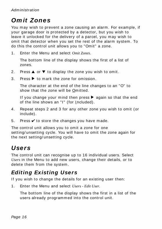
Omit Zones You may wish to prevent a zone causing an alarm. For example, if your garage door is protected by a detector, but you wish to leave it unlocked for the delivery of a parcel, you may wish to omit that detector when you set the rest of the alarm system. To do this the control unit allows you to "Omit" a zone.
1. Enter the Menu and select Omit Zones.
The bottom line of the display shows the first of a list of zones.
2. Press u or n to display the zone you wish to omit.
3. Press > to mark the zone for omission.
The character at the end of the line changes to an "O" to show that the zone will be Omitted.
If you change your mind then press > again so that the end of the line shows an "I" (for Included).
4. Repeat steps 2 and 3 for any other zone you wish to omit (or include).
5. Press Y to store the changes you have made.
The control unit allows you to omit a zone for one setting/unsetting cycle. You will have to omit the zone again for the next setting/unsetting cycle.
Users The control unit can recognise up to 16 individual users. Select Users in the Menu to add new users, change their details, or to delete them from the system.
Editing Existing Users If you wish to change the details for an existing user then:
1. Enter the Menu and select Users - Edit User.
The bottom line of the display shows the first in a list of the users already programmed into the control unit.
Administration
Page 17
2. Press u or n to display the user you wish to edit, and then press >.
The bottom line shows one of a list of the options that you can edit:
Name
Type (this option is not available for User 01)
Code
Prox Tag
Remotes
Panic Alarm
Use the u or n keys to scroll through the list.
(The options available are the same as those shown when adding a user.)
3. Press > to select the option you wish to edit.
4. Press Y when you have finished.
Name If you wish to edit the name displayed on the keypad for a user:
1. Select Users - Edit User - User(nn) - Name.
The display shows the current name given to the user, and places a cursor at the end of the name.
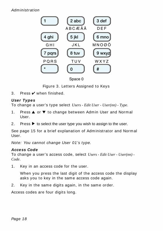
2. Key in the name from the keypad. Press each key one or more times to obtain the letter you want (the letters of the alphabet appear on the keys in the same arrangement as on many mobile phones, see Figure 3.)
Press # to change between capitals and small letters.
The cursor becomes an underline when you type in small letters and a block when you type in capitals.
Press u to move the cursor left, or n to move the cursor to the right.
Press < to remove letters to the left of the cursor. Press > to insert a space.
Administration
Page 18
1
4 ghi
7 pqrs
* 0 #
2 abc
5 jkl
3 def
6 mno
8 tuv 9 wxyz
A B C Æ Å Ä D E F
G H I J K L M N O Ø Ö
P Q R S T U V W X Y Z
Space 0
Figure 3. Letters Assigned to Keys
3. Press Y when finished.
User Types To change a user’s type select Users - Edit User - User(nn) - Type.
1. Press u or n to change between Admin User and Normal User.
2. Press > to select the user type you wish to assign to the user.
See page 15 for a brief explanation of Administrator and Normal User.
Note: You cannot change User 01’s type.
Access Code To change a user’s access code, select Users - Edit User - User(nn) - Code.
1. Key in an access code for the user.
When you press the last digit of the access code the display asks you to key in the same access code again.
2. Key in the same digits again, in the same order.
Access codes are four digits long.
Administration
Page 19
Proximity Tags A proximity tag is a small plastic token with a low powered radio transmitter inside. Each tag contains a unique identity code. Inside the keypad is a sensor. When you present the tag within about 10mm of the front of the keypad, the control unit senses the presence of the tag and reads its identity code.
If a user presents a tag that the control unit recognises then the control unit allows the user to access the system in the same way as if they had keyed in a recognised access code.
To allocate a tag to a user, select Users - Edit User - User(nn) - Prox Tag.
Note: If the user already has a prox tag allocated to them then the screen will display “Delete Prox Tag?”. See page 21.
The display asks you to present a tag to the front of the keypad.
1. Hold the tag up close to the front of the keypad.
The control unit learns the identity of the tag.
You cannot register more than one tag per user. If you present a tag that the control unit has already registered to another user then you will hear a single low tone, the display will tell that the tag is already in use and will then revert to asking you to present the tag.
If you do not wish to register a tag for the user then press X.
If you have a proximity tag and want to know who it belongs to then use the Test - Proximity Tag menu option, see page 24 .
Administration
Page 20
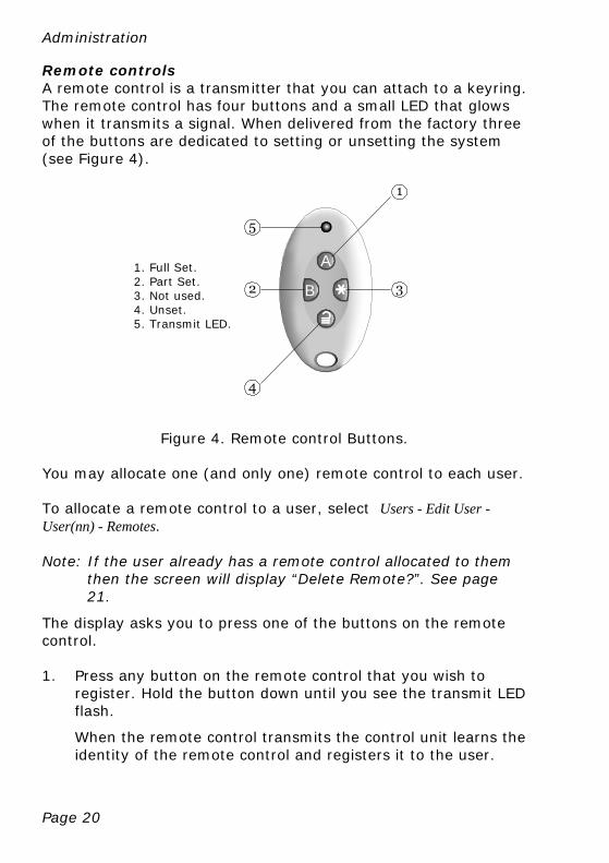
Remote controls A remote control is a transmitter that you can attach to a keyring. The remote control has four buttons and a small LED that glows when it transmits a signal. When delivered from the factory three of the buttons are dedicated to setting or unsetting the system (see Figure 4).
1. Full Set. 2. Part Set. 3. Not used. 4. Unset. 5. Transmit LED.
A
B
Figure 4. Remote control Buttons.
You may allocate one (and only one) remote control to each user.
To allocate a remote control to a user, select Users - Edit User - User(nn) - Remotes.
Note: If the user already has a remote control allocated to them then the screen will display “Delete Remote?”. See page 21.
The display asks you to press one of the buttons on the remote control.
1. Press any button on the remote control that you wish to register. Hold the button down until you see the transmit LED flash.
When the remote control transmits the control unit learns the identity of the remote control and registers it to the user.
Administration
Page 21
If you do not wish to register a remote control press X.
If the control unit has already learned that remote control then you will hear a low tone and the display tells you that the remote control is already in use.
If you have a remote control and want to know who it belongs to then use the Test - Remotes menu option, see page 24 .
Panic Alarms (PA) A PA is a two button transmitter, used to start a Panic Alarm. To activate the transmitter you must press both buttons at the same time. On some models a third button acts as a lock so that you can prevent the PA going off when carrying it in your pocket.
Note: While you are registering a new PA the control unit will not respond to an alarm signal from any PA it has already learned.
To allocate a panic alarm to a user, select Users - Edit User - User(nn) - Panic Alarm.
Note: If the user already has a PA allocated to them then the screen will display “Delete PA?”. See “Deleting Remote Controls, Tags and PAs” below.
The display asks you to press both buttons on the PA.
1. Squeeze both buttons on the PA.
When you squeeze the buttons the control unit learns the identity of the PA and registers it to the user.
If you do not wish to register a PA press X.
You cannot register more than one PA per user. If the control unit has already learned that PA then you will hear a low tone and the display remains unchanged, asking you to press the buttons on the PA.
If you have a PA and want to know who it belongs to then use the Test - Panic Alarms menu option, see page 24 .
Deleting Remote Controls, Tags and PAs If a user has lost a remote control, prox tag or panic alarm then you should delete it from the system to make sure that no
Administration
Page 22
unauthorised person can use it. Also, if you wish to reassign a device to another user, you must first delete it from the system.
1. Enter the Menu and select Users - Edit User.
The bottom line of the display shows the first in a list of the users currently recognised by the system.
2. Press u or n to display the user whose device you wish to delete., the press >.
The bottom line of the display shows “Name”.
3. Press u or n until the bottom line shows the device you wish to delete, then press >.
If the user you selected in step 2 has a device registered to them then the display asks if you wish to delete it, for example: “Delete Panic Alarm?”.
4. Press Y.
The display shows, for example, “Panic Alarm Deleted”.
To register a device with the user, re-enter the Menu and select Users - Edit User. Select the user and then the device type you wish to add.
Adding Users When adding a new user you can also assign to them proximity tags, remote controls and panic alarm transmitters. If you do not wish to assign these devices at thetime then you can assign them later by using the Users - Edit User option.
To add a new user:
1. Enter the Menu and select Users - Add User.
The display shows a default user name, for example: “User 04”. Edit the name as described on page 17,
2. Press Y when you have finished editing the name.
The display shows the default type for a new user (Normal User, see page 15 for a description of user types).
3. Select the type you want to assign to the new user and press Y.
Administration
Page 23
The display asks you to assign a new user code.
4. Key in the user code you want the new user to employ. Key it in a second time when prompted by the display.
The display asks you to present a proximity tag to the keypad.
5. Present an unused tag to the keypad. If you do not want to assign one to the user press Y.
The display then asks you to press a button on any remote control that you want to assign to the user.
6. Press a button on a remote control (one that is not currently registered to any other user). If you do not have one press Y.
The display finally asks you to press both buttons on any PA that you want to assign to the new user.
7. Press both buttons on a PA that you wish to assign to the user. If you do not have one for the user press Y.
The display should now tell you that the new user has been added to the system.
Deleting Users To remove a user from the system:
1. Enter the Menu and select Users - Delete User.
The bottom line of the display shows the first user in a list of the users recognised by the system.
2. Press u or n until the display shows the user you want to delete.
3. Press >.
The display shows the message “Delete All Details”.
(If you change your mind at this point press X.)
4. Press Y .
The control unit deletes the user from the system.
Administration
Page 24
Once you delete a user, the system does not respond to their access code or to their proximity tag. In addition, the control unit "forgets" the identity of all remote controls and PAs assigned to the user.
View Log The control unit keeps a log of the last 250 events (for example, alarms and setting/unsetting events). To read the log:
1. Enter the Menu and select View Log.
The display shows you the most recent log event.
2. Press u or n to scroll through the log.
n shows earlier events, u shows more recent events.
3. Press > to see a more detailed description of the event.
4. Press X to finish viewing the log.
Test If you think that your system is not working correctly then you can use the Test option to test various peripherals. If the test confirms that part of the system is not working then contact your installer.
The Test option also lets you check the identity of Remote controls, Panic Alarms and Tags.
To start testing, make sure the system is unset and the display shows the time and date then:
1. Enter the Menu and select Test.
The display shows the Test menu.
2. Press u or n to select the part of the system that you wish to test.
3. Press X to stop the test.
You can test each part listed in the Test menu as follows:

Administration
Page 25
Siren Press > to turn the siren on and off again. The word "On" or "Off" on the display shows whether you should be hearing the siren.
Keypad Press each key once. The display shows a character in response. Press both PA keys together to test. Press X to end the test.
Walk test The display shows a list of all the detectors installed on the system. The top line of the display shows you how many detectors remain to be tested. Walk round and trigger each detector. Every time you trigger a detector the control unit gives a double tone and the display shows an "A" at the end of the line for that detector. Note that you cannot test 24 hour or fire zones.
Remotes Press any button on the remote control. The display shows the identity and user of the remote control, and the button that the control unit believes you pressed. Press all the buttons on the remote control in turn.
Panic Alarms Press both buttons on the panic alarm transmitter. The display shows the identity of the user assigned to the panic alarm.
Proximity Tags Present the tag to the front of the keypad. The display shows the user assigned to the tag.
System Configuration The System Configuration option allows you to set up parts of the system to suit your particular needs. If you need more extensive changes to the operation of the system then you must contact your installer.
Make sure the system is unset and the display shows the time and date, then:
1. Enter the Menu and select System Config.
Administration
Page 26
The bottom line of the display shows the first item of the System Configuration menu.
2. Press u or n to scroll through the options available, followed by > to gain access to an option.
Facilities On/Off Chime The installer may have set up your alarm system to give a chime tone whenever something triggers one or more detectors while the system is unset. If you wish to switch this feature off (or on) then:
1. Enter the System Config menu and select Chime.
The bottom line of the display shows the current state of the chime feature, for example “Chime On” if chime is currently working.
2. Press > till the bottom line of the display shows the status you want (for example “Chime Off” if you want to silence the chime feature).
3. Press Y to leave the option when you have finished making changes.
Set Date and Time
You will need to re-program the date and time if the control unit looses power for an extended time, and the battery is exhausted.
1. Enter the System Config menu and select Set Time/Date.
The top line of the display shows “Set the date” and the bottom line shows the current date in number format (day/month/year). The day is highlighted.
2. Key in the digits for the day/month/year. Press Y when you have finished.
The top line of the display shows “Set the time” and the bottom line of the display shows the current time in 24 hour numerical format (hours: minutes). The hours are highlighted.
3. Key in the hours and minutes. Press Y to finish.
Administration
Page 27
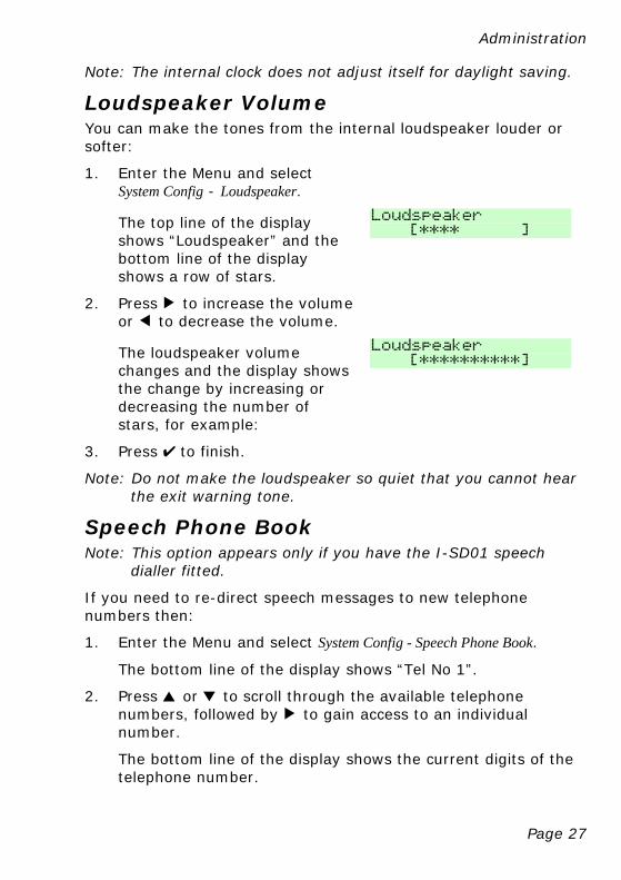
Note: The internal clock does not adjust itself for daylight saving.
Loudspeaker Volume You can make the tones from the internal loudspeaker louder or softer:
1. Enter the Menu and select System Config - Loudspeaker.
The top line of the display shows “Loudspeaker” and the bottom line of the display shows a row of stars.
Loudspeaker [**** ]
2. Press > to increase the volume or < to decrease the volume.
The loudspeaker volume changes and the display shows the change by increasing or decreasing the number of stars, for example:
Loudspeaker
[**********]
3. Press Y to finish.
Note: Do not make the loudspeaker so quiet that you cannot hear the exit warning tone.
Speech Phone Book Note: This option appears only if you have the I-SD01 speech
dialler fitted.
If you need to re-direct speech messages to new telephone numbers then:
1. Enter the Menu and select System Config - Speech Phone Book.
The bottom line of the display shows “Tel No 1”.
2. Press u or n to scroll through the available telephone numbers, followed by > to gain access to an individual number.
The bottom line of the display shows the current digits of the telephone number.
Administration
Page 28
3. Key in the new telephone number from the keypad. If necessary, press u to move the cursor left, or n to move the cursor to the right. Press < to remove digits to the left of the cursor.
4. Press Y to store the changes you have made.
Page 29
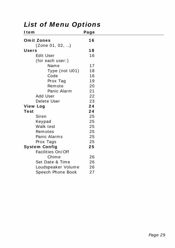
List of Menu Options Item Page
Omit Zones 16 (Zone 01, 02, …)
Users 18 Edit User 16 (for each user:)
Name 17 Type (not U01) 18 Code 16 Prox Tag 19 Remote 20 Panic Alarm 21
Add User 22 Delete User 23
View Log 24 Test 24
Siren 25 Keypad 25 Walk test 25 Remotes 25 Panic Alarms 25 Prox Tags 25
System Config 25 Facilities On/Off
Chime 26 Set Date & Time 26 Loudspeaker Volume 26 Speech Phone Book 27

Page 30
© Cooper Security Ltd. 2008
Every effort has been made to ensure that the contents of this book are correct. However, neither the authors nor Cooper Security Limited accept any liability for loss or damage caused or alleged to be caused directly or indirectly by this book. The contents of this book are subject to change without notice.
Printed and published in the U.K
Part Number 11847976 Issue 2
Warning: Mains voltages are present inside control unit. No user serviceable parts inside.