security requirements modeling tool secbpmn2 …secbpmn2 plugin user guide (version 1.0.0) 1...
TRANSCRIPT
Security Requirements
Modeling Tool
SecBPMN2 Modeler
User Guide (rev 1.0)
For STS-Tool Version 2.1
Contact: [email protected]
I
Table of contents
Introduction ........................................................................................................... 1
Background ......................................................................................................... 1
Document Conventions ........................................................................................... 1
Installation .......................................................................................................... 2
Project Resources ................................................................................................. 2
Anatomy of the SecBPMN2 Plugin ................................................................................. 3
Secure business process editor .................................................................................. 3
Security policy editor ............................................................................................. 3
Template editors .................................................................................................. 4
Secure business process template editor ................................................................... 4
Security policy template editor .............................................................................. 5
STS-ml and SecBPMN2 integration ................................................................................. 6
Extend existing project with SecBPMN2 features ............................................................... 7
SecBPMN2 New File Wizards ........................................................................................ 8
Generation of report ................................................................................................. 8
Graphical editors anatomy .......................................................................................... 9
Editor Tabs .......................................................................................................... 9
Drawing Canvas ................................................................................................... 10
Tool Palette ....................................................................................................... 10
Outline View ....................................................................................................... 10
Property View ..................................................................................................... 10
Menu & Toolbar ................................................................................................... 10
Graphical Editing .................................................................................................... 11
Tool Palette ....................................................................................................... 11
Context Button Pad .............................................................................................. 12
Connections ........................................................................................................ 14
Property View ........................................................................................................ 15
Editing Widgets ................................................................................................... 15

II
Property Tabs ..................................................................................................... 17
Process Diagram ................................................................................................ 17
Process Tab .................................................................................... 17
Interfaces Tab ................................................................................. 18
Definitions Tab................................................................................. 19
Data Items Tab ................................................................................ 22
Activity .......................................................................................................... 23
Standard Loop Characteristics ............................................................... 23
Multi-Instance Loop Characteristics ........................................................ 24
I/O Parameters ................................................................................ 26
Ad Hoc Sub-Process ........................................................................... 30
Business Rule Task ............................................................................ 30
Call Activity .................................................................................... 31
Receive Task ................................................................................... 31
Script Task...................................................................................... 32
Send Task ....................................................................................... 33
Service Task .................................................................................... 33
Sub-Process ..................................................................................... 34
Transaction ..................................................................................... 34
User Task ....................................................................................... 34
Gateway ......................................................................................................... 35
Events ............................................................................................................ 36
Event Definitions With Data Items .......................................................... 37
Data Items ....................................................................................................... 39
Sequence Flows ................................................................................................ 40
Security annotations .......................................................................................... 40
Accountability ................................................................................. 40
Auditability ..................................................................................... 41
Authenticity .................................................................................... 41
Availability ..................................................................................... 41
Confidentiality ................................................................................. 41
Integrity ........................................................................................ 41
Non-repudiation ............................................................................... 42
Privacy .......................................................................................... 42
III
Separation of duty ............................................................................ 42
Bind of duty .................................................................................... 42
Non delegation ................................................................................. 42
Mapping view ......................................................................................................... 42
Outline View .......................................................................................................... 43
Popup Dialogs ........................................................................................................ 44
BPMN2 Element Property Dialogs .............................................................................. 44
Data Type Dialog .................................................................................................. 45
Variable Dialog .................................................................................................... 45
Message Dialog .................................................................................................... 46
Error Dialog ........................................................................................................ 46
Signal Dialog ....................................................................................................... 47
Escalation Dialog .................................................................................................. 47
Data Store Dialog ................................................................................................. 47
Import Editing Dialog ............................................................................................ 48
Resource Dialog ................................................................................................... 49
Resource Parameter Dialog .................................................................................. 49
Resource Role Dialog ............................................................................................. 49
Export Diagram Dialog ........................................................................................... 50
User Preferences .................................................................................................... 50
General Settings .................................................................................................. 50
Editor Appearance ................................................................................................ 51
Editor Behavior .................................................................................................... 53
Automated analysis ................................................................................................. 54
Generation of security policies................................................................................. 54
Verification of security policies ................................................................................ 55
Figures and Tables .................................................................................................. 58
References ............................................................................................................ 61

SecBPMN2 plugin User Guide (Version 1.0.0)
1
INTRODUCTION
SecBPMN2 plugin for STS-Tool is a graphical tool for authoring and editing secure business process
models (using SecBPMN2-ml modeling language) and procedural security policies (using SecBPMN2-Q
modeling language), verifying procedural security policies against secure business processes,
generating security documents.
It is assumed that the reader is familiar with SecBPMN2 and its applications; discussions about the
details of the BPMN 2.0 specification are beyond the scope of this document. For further details on
SecBPMN please refer to [1].
This document covers version 1.0 of SecBPMN2 plugin, and extends BPMN 2.0 Modeler
documentation published November 15, 2013.
BACKGROUND
SecBPMN2 plugin was designed and developed by Paolo Giorgini, Mattia Salnitri and Mauro
Poggianella, which are part of the software engineering and formal method groups of University of
Trento, Italy.
The main objective of the SecBPMN2 plugin is to support the STS framework [2]. This is achieved by
supporting the modeling of secure business processes (using SecBPMN2-ml modeling language),
security policies (using SecBPMN2-Q modeling language), and the integration between STS-ml and
SecBPMN2 models. SecBPMN2 plugin support the whole enforcement chain of security requirement
by generating security documents.
DOCUMENT CONVENTIONS
Menu actions, mouse click commands or any other UI labels or callouts are in bold:
Delete – deletes the selected element.
Sequences of actions that involve cascading menus are separated with an arrow:
From the main menu, click Help -> Install New Software
Sometimes it is necessary to distinguish between references to specific SecBPMN2 model elements
and the concepts they represent. For example SecBPMN2 defines a Process element, but we may
also refer to a process in a broader sense outside the context of the SecBPMN2 model. Whenever a
SecBPMN2 model element is discussed, it will be highlighted in a different color and font:
A Sequence Flow is used to show the order in which Activities will be performed.
Usage Tips and hints are highlighted with a border:
The Description text can be hidden by changing the Editor Behavior preferences.
Actions that may cause unexpected results are highlighted with a border:
If any of the above attributes are changed as a result of these settings,
those changes will be reflected in the file when it is saved.

SecBPMN2 plugin User Guide (Version 1.0.0)
2
Hyperlinks to other sections of the document are highlighted and underlined:
See the Context Button Pad section for more information.
INSTALLATION
The SecBPMN2 plugin is installed from STS-Tool. From the main menu, select Help -> Install New
Software (Figure 1). Next, select from the list of available plugins the SecBPMN2 plugin, as shown in
(Figure 2) and click Finish. Once the software has been installed, STS-Tool will restart
automatically.
Figure 1 Install software menu
Figure 2 Install Software Wizard Dialog
PROJECT RESOURCES
Please visit the STS-Tool project website for new release announcements and other news
concerning the project, here:
http://www.sts-tool.eu/

SecBPMN2 plugin User Guide (Version 1.0.0)
3
ANATOMY OF THE SecBPMN2 PLUGIN
SecBPMN2 is composed by a textual editor for BPMN XML SOURCE and four graphical editors: for
SecBPMN2-ml business processes, for SecBPMN2-Q security policies, for SecBPMN2-ml business
process templates and for SecBPMN-Q security policies templates.
The graphical editors are composed of the Drawing Canvas in the main area of the editor window,
collapsible Tool Palette on the right, tabbed Property sheets, and an Outline Viewer with both tree
and thumbnail views.
SECURE BUSINESS PROCESS EDITOR
The secure business process editor uses SecBPMN2-ml, a modeling language that extends BPMN 2.0
modeler with a set of security annotations. Figure 3 shows the secure business process editor with a
SecBPMN2-ml model and the palette on the left.
The editor automatically checks the compliance of the model against the BPMN 2.0 standard. It is
possible to remove such control by clicking on “Disable Validation” in the Diagram menu, as shown
in Figure 4.
Figure 3 Secure Business Process Editor
Figure 4 Disable validation
SECURITY POLICY EDITOR
STS-Tool permits to model security policies with the security policy editor. This editor uses
SecBPMN2-Q modeling language, an extension of SecBPMN2-ml with a set of relations, which can be
found in the group SecBPMN-Q in the palette.
The tools permit to specify if a security policy is a pattern or an anti-pattern, i.e., if the security
policy describes a behavior that all business process shall follow, in the former case, or that they
shall NOT follow, in the latter case. This property can be set in the Pattern tab of the Property
view, as shown in Figure 5. The value of such property is shown with a colored border around the

SecBPMN2 plugin User Guide (Version 1.0.0)
4
security policy editor: if the border is red the policy is an anti-pattern, if it is green, the policy is a
pattern.
Figure 5 Security Policy Editor
TEMPLATE EDITORS
Templates are used to generate SecBPMN2-ml secure business processes from STS-ml elements and
SecBPMN2-Q security policies from STS-ml security requirements.
SECURE BUSINESS PROCESS TEMPLATE EDITOR
Business process templates are used for the automated generation of SecBPMN2-ml secure business
processes from STS-ml elements.
To create a business process template, right click on a project folder and select New Business
Process Template. This will create a new template in the folder Business Process Templates in
Collaboration in Templates folder, of the selected project.
A double click on a business process template file will open the associated editor. The editor is
divided in two parts, as shown in Figure 6. The upper part shows the STS-ml element associated to
the template, the lower part contains the SecBPMN2 model that will be generated using the
template. It is possible to hide the upper part, by clicking on the arrow in the upper left part of the
editor.

SecBPMN2 plugin User Guide (Version 1.0.0)
5
Figure 6 Secure Business Process Template Editor
In the business process template editor the Mapping view connects the STS-ml elements shown in
the upper part of the editor with the SecBPMN2 elements in the lower part of the editor. The
information about the mapping in the template will be used to create the mapping of the
generated business process.
It is possible to use the name of the STS-ml elements to generate the names of SecBPMN2
elements. The string ${<ref>} refers to the STS-ml element ref and, when the template is used to
generate a business process, the name of the STS-ml element will be substituted to the string.
The tool generates unique names for tasks and events whose names are left empty in the template.
SECURITY POLICY TEMPLATE EDITOR
Security policy templates are used for the automated generation of SecBPMN2-Q security policies
from STS-ml security requirements.
To create a security policy template, right click on a project folder and select New Security policy
Template. This will create a new template in the folder Security Policy Templates in the
Collaboration inside Templates folder, of the selected project.
The Security policy template editor is similar to the business process template editor except for the
naming of the SecBPMN2 elements. Once a SecBPMN2 element is mapped to an STS-ml element,
using the mapping view described in Mapping view, its name automatically changes to MAPPED. This
indicates that the element is mapped and, when a security policy will be generated from an STS-ml
security requirement, its name will be changed into the SecBPMN2-ml element mapped to the STS-
ml element contained in the security requirements.

SecBPMN2 plugin User Guide (Version 1.0.0)
6
Figure 7 Security Policy Template Editor
STS-ML AND SecBPMN2 INTEGRATION
The modeling editors of STS-ml and SecBPMN2 are well integrated.
From STS-ml editor is possible to generate SecBPMN2 diagrams. To generate a business process,
right click on the STS-ml elements to open the contextual menu, then select Create business
process diagram, as shown in Figure 8. This action will generate the business process and will open
the secure business process editor with the generated model.
Figure 8 Create Business Process for STS Diagram
Is possible to open a secure business process associated to an STS-ml element. To open the model
access to the contextual menu of the element and click on Edit Business Process Diagram, as
shown in Figure 9.
Figure 9 Edit / Delete Business Process for STS Diagram
Is possible to delete the generated secure business process directly from the STS-ml editor: right
click on the STS-ml element to open the contextual menu and select Remove business process
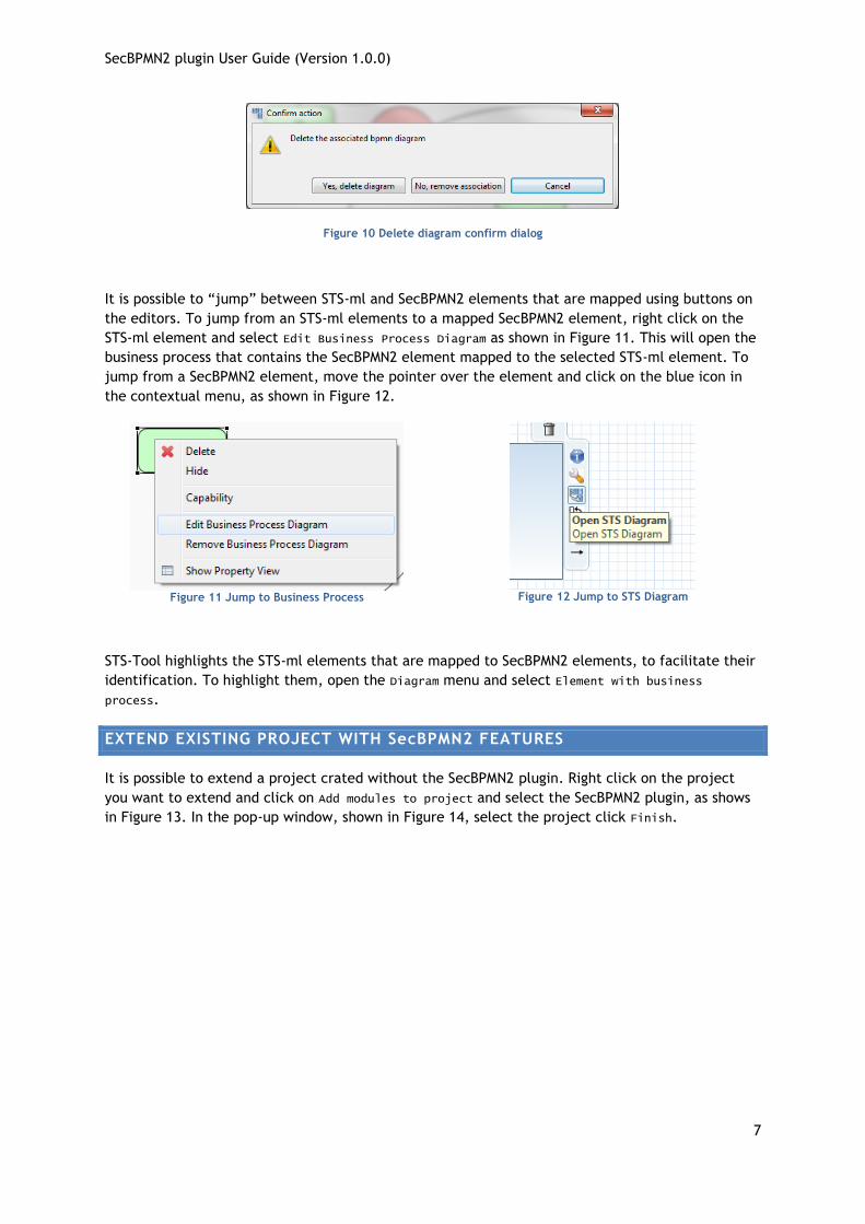
diagram, as shown in Figure 9. This action will open a dialog, shown in Figure 10 where is possible to
choose to delete the diagram or the association between the element and the business process.
SecBPMN2 plugin User Guide (Version 1.0.0)
7
Figure 10 Delete diagram confirm dialog
It is possible to “jump” between STS-ml and SecBPMN2 elements that are mapped using buttons on
the editors. To jump from an STS-ml elements to a mapped SecBPMN2 element, right click on the
STS-ml element and select Edit Business Process Diagram as shown in Figure 11. This will open the
business process that contains the SecBPMN2 element mapped to the selected STS-ml element. To
jump from a SecBPMN2 element, move the pointer over the element and click on the blue icon in
the contextual menu, as shown in Figure 12.
Figure 11 Jump to Business Process
Figure 12 Jump to STS Diagram
STS-Tool highlights the STS-ml elements that are mapped to SecBPMN2 elements, to facilitate their
identification. To highlight them, open the Diagram menu and select Element with business
process.
EXTEND EXISTING PROJECT WITH SecBPMN2 FEATURES
It is possible to extend a project crated without the SecBPMN2 plugin. Right click on the project
you want to extend and click on Add modules to project and select the SecBPMN2 plugin, as shows
in Figure 13. In the pop-up window, shown in Figure 14, select the project click Finish.

SecBPMN2 plugin User Guide (Version 1.0.0)
8
Figure 13 Add module context menu
Figure 14 Add Module Wizard
SecBPMN2 NEW FILE WIZARDS
In order to create a new SecBPMN2 file, in the Main Menu, click File and select the type of file you
want to create. There are four possible choices: secure business process, secure business process
template, security policy or security policy template. Figure 15 shows the menu.
Figure 15 New SecBPMN2 File
GENERATION OF REPORT
SecBPMN2 Plugin can generate automatically security requirement documents, which contain
information specified in STS-ml and SecBPMN2 models, and the results of the automated analysis
executed.
The installation of SecBPMN2 plugin does not change the generation interface. There are more
options because the reports include secure business processes, security policies, and the results of
the analysis.

SecBPMN2 plugin User Guide (Version 1.0.0)
9
GRAPHICAL EDITORS ANATOMY
All SecBPMN2 Plugin graphical editors are composed by: an editor tab, a drawing canvas, a tool
palette, an outline view, a property views a special button in the toolbar. All components are
described below.
EDITOR TABS
The SecBPMN2-ml editor has multiple pages, or tabs; each tab is used to display a separate BPMN
Diagram.
Figure 16 SecBPMN2 Editor multiple Diagrams
Note that there are two sets of tabs: one set at the top of the editor window and another set at the
bottom. The tabs at the top are used to flip between different diagrams, while the ones at the
bottom are the contents of collapsed Sub-Processes contained within the same diagram. Procedures
for managing diagram and Sub-Process tabs will be discussed in a later section.
A special tab is available for an XML source view of the BPMN diagram, as shown in the following
screenshot.
Figure 17 XML Source View
SecBPMN2 plugin User Guide (Version 1.0.0)
10
The XML view is read-only as of this version, however fully synchronized text
and graphical editing is planned for a future release.
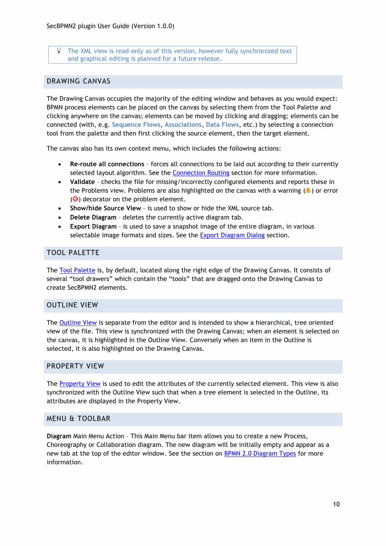
DRAWING CANVAS
The Drawing Canvas occupies the majority of the editing window and behaves as you would expect:
BPMN process elements can be placed on the canvas by selecting them from the Tool Palette and
clicking anywhere on the canvas; elements can be moved by clicking and dragging; elements can be
connected (with, e.g. Sequence Flows, Associations, Data Flows, etc.) by selecting a connection
tool from the palette and then first clicking the source element, then the target element.
The canvas also has its own context menu, which includes the following actions:
Re-route all connections – forces all connections to be laid out according to their currently
selected layout algorithm. See the Connection Routing section for more information.
Validate – checks the file for missing/incorrectly configured elements and reports these in
the Problems view. Problems are also highlighted on the canvas with a warning ( ) or error
( ) decorator on the problem element.
Show/hide Source View – is used to show or hide the XML source tab.
Delete Diagram – deletes the currently active diagram tab.
Export Diagram – is used to save a snapshot image of the entire diagram, in various
selectable image formats and sizes. See the Export Diagram Dialog section.
TOOL PALETTE
The Tool Palette is, by default, located along the right edge of the Drawing Canvas. It consists of
several “tool drawers” which contain the “tools” that are dragged onto the Drawing Canvas to
create SecBPMN2 elements.
OUTLINE VIEW
The Outline View is separate from the editor and is intended to show a hierarchical, tree oriented
view of the file. This view is synchronized with the Drawing Canvas; when an element is selected on
the canvas, it is highlighted in the Outline View. Conversely when an item in the Outline is
selected, it is also highlighted on the Drawing Canvas.
PROPERTY VIEW
The Property View is used to edit the attributes of the currently selected element. This view is also
synchronized with the Outline View such that when a tree element is selected in the Outline, its
attributes are displayed in the Property View.
MENU & TOOLBAR
Diagram Main Menu Action – This Main Menu bar item allows you to create a new Process,
Choreography or Collaboration diagram. The new diagram will be initially empty and appear as a
new tab at the top of the editor window. See the section on BPMN 2.0 Diagram Types for more
information.

SecBPMN2 plugin User Guide (Version 1.0.0)
11
Undo/Redo – These Toolbar actions undo or redo the last editing operation performed. If the
operation changed some attribute of an element (for example, its name) the undo/redo affects
only that attribute.
Zoom – This Toolbar action are used to magnify or reduce the diagram.
Alignment Tools – These Toolbar actions are used to align multiple shapes
with each other either horizontally, vertically, or normalize their widths or heights.
Hide Context Buttons – This Toolbar action disables the Context Button Pad. When the mouse
is hovered over an element, an irregularly shaped “pad” pops up and surrounds the element. This
pad contains a number of editing buttons which affect the element. The Hide Context Buttons
Toolbar toggle button disables the display of this Button Pad. See the Context Button Pad section
for more information.
GRAPHICAL EDITING
This section explains the use of the graphical editor and all user gestures (mouse clicks, keyboard
actions, etc.) in more detail.
TOOL PALETTE
The Tool Palette appears along the right edge of the Drawing Canvas, although it can also be
“docked” at the left edge. It consists of several “tool drawers” which can be individually expanded
and collapsed, or pinned open (see screenshot at left).
Figure 18 Tool Palette

SecBPMN2 plugin User Guide (Version 1.0.0)
12
The Tool Palette can also be collapsed to save screen real-estate, using the button in the title
bar.
Tool Drawers contain any number of “tools” which are categorized either as Selection Tools,
Connector Tools or Creation Tools. The category defines their behavior:
Selection Tools remain active as long as they are enabled. The Select tool allows you to select
individual elements on the Drawing Canvas by clicking the primary (left) mouse button; holding
either the Control or Shift key allows you to select additional elements. The Marquee tool is used
to select multiple elements by dragging a rectangular selection box around the elements.
Additional elements can be selected by switching back to the Select tool.
Connector Tools also remain active as long as they are enabled. To create a connection between
two elements, click the first element (the “source” of the connection) and then the second (the
“target”).
Creation Tools are “single shot”, that is they are only active for a single mouse click action. Once
the element has been created on the Drawing Canvas, the Select tool becomes active again.
Pressing the ESC key while a tool is active cancels its action, and re-activates the Select tool.
The Tool Palette’s behavior and appearance can be adjusted in the Settings dialog which is
accessible from its context menu, as shown here:
Figure 19 Tool Palette Configuration
CONTEXT BUTTON PAD
As mentioned in the Anatomy of the SecBPMN2 plugin section, when the mouse is hovered over a
shape, a Context Button Pad appears for that shape as shown here:
Figure 20 Context Button Pad
SecBPMN2 plugin User Guide (Version 1.0.0)
13
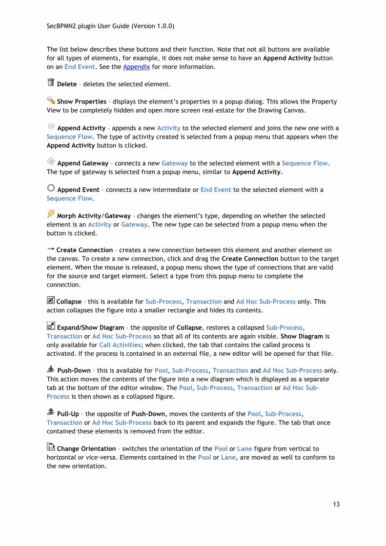
The list below describes these buttons and their function. Note that not all buttons are available
for all types of elements, for example, it does not make sense to have an Append Activity button
on an End Event. See the Appendix for more information.
Delete – deletes the selected element.
Show Properties – displays the element’s properties in a popup dialog. This allows the Property
View to be completely hidden and open more screen real-estate for the Drawing Canvas.
Append Activity – appends a new Activity to the selected element and joins the new one with a
Sequence Flow. The type of activity created is selected from a popup menu that appears when the
Append Activity button is clicked.
Append Gateway – connects a new Gateway to the selected element with a Sequence Flow.
The type of gateway is selected from a popup menu, similar to Append Activity.
Append Event – connects a new intermediate or End Event to the selected element with a
Sequence Flow.
Morph Activity/Gateway – changes the element’s type, depending on whether the selected
element is an Activity or Gateway. The new type can be selected from a popup menu when the
button is clicked.
Create Connection – creates a new connection between this element and another element on
the canvas. To create a new connection, click and drag the Create Connection button to the target
element. When the mouse is released, a popup menu shows the type of connections that are valid
for the source and target element. Select a type from this popup menu to complete the
connection.
Collapse – this is available for Sub-Process, Transaction and Ad Hoc Sub-Process only. This
action collapses the figure into a smaller rectangle and hides its contents.
Expand/Show Diagram – the opposite of Collapse, restores a collapsed Sub-Process,
Transaction or Ad Hoc Sub-Process so that all of its contents are again visible. Show Diagram is
only available for Call Activities; when clicked, the tab that contains the called process is
activated. If the process is contained in an external file, a new editor will be opened for that file.
Push-Down – this is available for Pool, Sub-Process, Transaction and Ad Hoc Sub-Process only.
This action moves the contents of the figure into a new diagram which is displayed as a separate
tab at the bottom of the editor window. The Pool, Sub-Process, Transaction or Ad Hoc Sub-
Process is then shown as a collapsed figure.
Pull-Up – the opposite of Push-Down, moves the contents of the Pool, Sub-Process,
Transaction or Ad Hoc Sub-Process back to its parent and expands the figure. The tab that once
contained these elements is removed from the editor.
Change Orientation – switches the orientation of the Pool or Lane figure from vertical to
horizontal or vice-versa. Elements contained in the Pool or Lane, are moved as well to conform to
the new orientation.

SecBPMN2 plugin User Guide (Version 1.0.0)
14
Whitebox – this is available for Choreography Participant Bands only. This action creates a
new diagram tab that contains the Process for the Participant Band. This action is similar to Push-
Down, with the exception that a Participant Band cannot be used to display the underlying Process
as embedded elements.
Blackbox – this is the opposite of Whitebox. This action deletes the Process and diagram tab
associated with the Participant Band.
Add Participant Band – available for Choreography Tasks only. This action adds a new
Participant Band to the Choreography Task. Note that a Choreography Task may have any
number of Participants, but only one of them can be the Initiator. See the Appendix for an
explanation of Participants and Choreographies.
Remove Participant Band – available for Choreography Participant Bands only. This action
removes a Participant Band from its Choreography Task.
Add Message – available for Choreography Participant Bands only. This action adds a Message
to the Participant Band.
Remove Message – available for Choreography Participant Bands only. This action removes the
Message attached to the Participant Band. This has the same effect as selecting the attached
Message and deleting it.
Jump to STS model – available for Participant Band and Task only. This action will open the STS
model associated to the element.
CONNECTIONS
Connections between shapes can be created in one of three ways: using the Connector tools from
the Tool Palette, using the Create Connection Context Button and implicitly using the Append
Context buttons.
When a Connection is selected, one or more “handles” will appear on the connection line. The
connection’s path can be altered by dragging one of these handles. Note that new handles will
appear as a handle is dragged to create new line segments. The locations of these handles are
known as “bendpoints” to the graphical editor, but are stored as Waypoint elements in the BPMN
file.
SecBPMN2 allows you to specify different layout styles (“Routings”) for connections. Routing styles
are applied by connection type, so for example, all Sequence Flows can be laid out using
Manhattan routing, all Associations can use Manual Bendpoint routing, and so on. The Editor
Appearance Preferences section explains how to configure connection routing styles.
Connections may also have labels, which are edited using the Property View. The labels are
situated about the center of the connection, but may be dragged to a different location with the
mouse.

SecBPMN2 plugin User Guide (Version 1.0.0)
15
PROPERTY VIEW
The Property View is used to edit all parameters for the currently selected SecBPMN2 element.
SecBPMN2 plugin uses tabbed property sheets that are based on Eclipse Forms widgets (see
screenshot below).
Figure 21 Tabbed Property View
Although the number of tabs and their contents depends on which SecBPMN2 element is selected,
the first tab of each element is similar. This is the Description tab which contains the element’s
name (if it has one), a brief description of the element type, and a Documentation edit box which
can be used to document the element.
The Description text can be hidden by changing the Editor Behavior preferences.
The element’s ID attribute will also be displayed on this tab, if its visibility is enabled (see Editor
Behavior preferences.)
EDITING WIDGETS
If you are familiar with Eclipse Forms, most of the Property View editing widgets should be familiar
(e.g. Text Editing fields, Check Boxes, Combo Boxes, etc.) The Eclipse Plug-in Manifest editor is an
example of how these Form widgets look and behave.
SecBPMN2 Plugin inherit the unique editing widget of BPMN2 Modeler, which deserves further
explanation, called the “List and Detail”. This is essentially a table (the “List”) with several editing
controls at the top, and an optional Detail panel that pops out to the right when the edit button
is clicked. The figures below illustrate the List and Detail widget in its normal and expanded form:

SecBPMN2 plugin User Guide (Version 1.0.0)
16
Figure 22 List and Detail widget in normal and expanded views
Here the List portion of the widget is automatically collapsed to make room for the Detail panel,
which appears to the right of the List. The Detail panel typically contains more information than
can be displayed in the List.
List and Detail widgets can also be nested, as shown here with the Interfaces tab:
Figure 23 Nested List and Detail widgets
Here, the Interface Details panel contains an Operation List and Detail, which is also shown
expanded.
You may wish to use a popup dialog instead of the sliding Detail Panel. See the Editor Behavior preferences section for information.
The List and Detail widget control buttons should already be familiar:
Add a new entry to the List
Remove an entry from the List.
Re-order items in the List.
Edit the selected List item by opening the Detail panel to the right of the List, or a
popup dialog depending on preference.
Delete the selected entry entirely from the model. This is different from in that the
selected entry and all of its contained entries (as with the Interface List mentioned above)
are deleted.
Close the Detail panel

SecBPMN2 plugin User Guide (Version 1.0.0)
17
This button is seen in conjunction with other Text widgets and typically opens a
new Dialog from which values can be selected for the Text widget.
PROPERTY TABS
In this section we discuss all of the Property Tabs and their contents for each of the SecBPMN2
element categories.
PROCESS DIAGRAM
This Property Tab is displayed when the Drawing Canvas is clicked, or if a Process element is
selected from the Outline View.
PROCESS TAB
The Process tab defines attributes specific to the selected Process:
Figure 24 Process Tab
Name – the Process name for identification purposes only. This may or may not be required
by the execution engine.
Process Type – can be either “Private” or “Public”; “None” indicates no decision has been
made about the Process Type and is flagged as an error by the BPMN2 Core validator.
o Private – indicates the Process is internal to a specific organization. A Private
Process can be either executable or non-executable (see below.)
o Public – represents the interaction between a Private Business Process and another
Process or Participant
Is Executable – indicates if the Process is designed to be executable or not. If this box is
checked, the Process must contain enough information so it can be deployed to an
execution engine. Thus, information needed for execution, such as formal condition
Expressions are typically not included in a non-executable Process.
Is Closed - In some applications it is useful to allow additional Messages to be sent between
Participants that may not be explicitly declared in the Collaboration. If this box is checked
then Participants may not send any Messages other than those declared.

SecBPMN2 plugin User Guide (Version 1.0.0)
18
INTERFACES TAB
The Interfaces tab contains Process Interface definitions:
Figure 25 Interfaces Tab
Interface List – list of all defined Interfaces, both consumed and exposed. Clicking the
button displays the Interface Definition details:
o Name – the Interface name
o Implementation – the concrete artifact in the underlying implementation
technology, such as a WSDL Port Type.
o Operation List – a list of the Operations provided by the Interface. Clicking the
button displays the Operation Definition details:
Name – the Operation name
Implementation – the artifact in the underlying implementation
technology, such as a WSDL Operation.
In Message – the request message definition provided by the Process and
sent to the service that implements this Interface. Messages are defined in
the Definitions tab, below.
Out Message – the response message returned by the invoked service.

SecBPMN2 plugin User Guide (Version 1.0.0)
19
Error Refs – a list of possible error responses that may be returned by the
invoked service. Errors are defined in the Definitions tab, below.
Interfaces Provided by Process – lists only those Interfaces exposed by this Process.
Clicking the button allows you to select from the list of defined Interfaces.
DEFINITIONS TAB
The Definitions tab defines a list of imported resources, Data Types, Messages, Errors, Signals,
Escalations and Resources. This tab also contains additional process attributes as follows:
Figure 26 Definitions Tab
Name – the name of the root element of this XML document. This is different from the
Process name, primarily for documentation purposes.
Target Namespace – the Target Namespace of this XML document. This will be specific to
the organization or service that owns this process.
Type Language – identifies the type system used by the data elements in this file. By
default, this is http://www.w3.org/2001/XMLSchema but may be any URI supported by the
Target Runtime.
Expression Language – identifies the default language implementation used in condition
expressions. The Default is http://www.w3.org/1999/XPath but can be overridden for each
expression as needed.
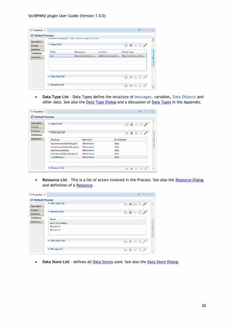
Import List – Imports are external files that may define data structures, services,
processes, etc. that are required by this Process. See also File Import Dialog.
SecBPMN2 plugin User Guide (Version 1.0.0)
20
Data Type List – Data Types define the structure of Messages, variables, Data Objects and
other data. See also the Data Type Dialog and a discussion of Data Types In the Appendix.
Resource List – This is a list of actors involved in the Process. See also the Resource Dialog
and definition of a Resource.
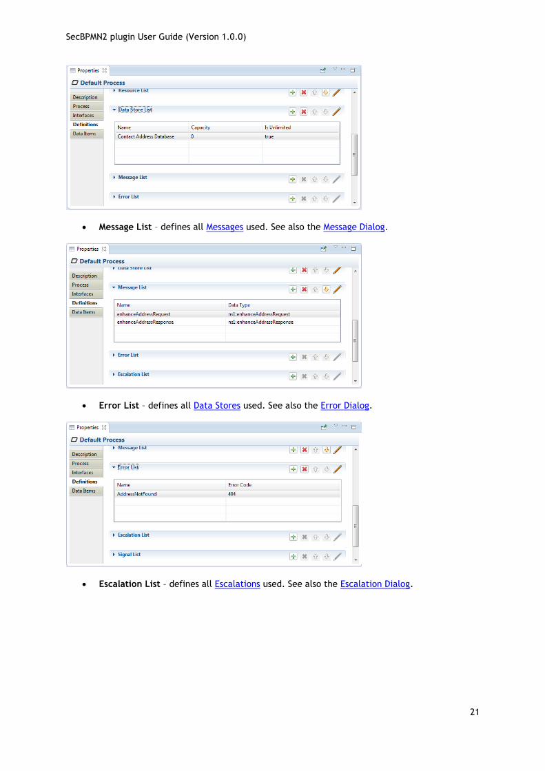
Data Store List – defines all Data Stores used. See also the Data Store Dialog.
SecBPMN2 plugin User Guide (Version 1.0.0)
21
Message List – defines all Messages used. See also the Message Dialog.
Error List – defines all Data Stores used. See also the Error Dialog.
Escalation List – defines all Escalations used. See also the Escalation Dialog.

SecBPMN2 plugin User Guide (Version 1.0.0)
22
Signal List – defines all Signals used. See also the Signal Dialog.
DATA ITEMS TAB
The Data Items tab contains global Process variable and Resource Role definitions. See the Variable
Dialog and the discussion of Variables in the Appendix. Also see the Resource Dialog and the
discussion of Resources in the Appendix for more information.
Figure 27 Data Items Tab

SecBPMN2 plugin User Guide (Version 1.0.0)
23
ACTIVITY
This section describes the Property Tabs used for of these Activities:
Task Business Rule Task Service Task User Task
Manual Task Receive Task Sub-Process Ad Hoc Sub-Process
Script Task Send Task Transaction Call Activity
Each specialized Activity has its own Property tab (see the following sections), but all contain these
common items:
Figure 28 Manual Task Tab
Is For Compensation – if this box is checked this Activity is only activated when a
Compensation Event is detected and initiated; if not checked, the Activity is run as part of
normal execution flow.
Loop Characteristics – determines whether the Activity is run once (Loop Characteristics =
“None”) or multiple times (“Standard” and “Multi-Instance”), and whether instances of the
Activity run concurrently or in parallel. This property is quite complicated and is discussed
in more detail in the following sections.
Variable List – list of “local” variables. Local variables are visible only to the Activity itself,
not to the Process or other Activities. See the Variable Dialog and the discussion of
Variables in the Appendix for more information.
Resource List – defines the resource that will perform or will be responsible for the
Activity. See the Resource Dialog and the discussion of Resources in the Appendix for more
information.
STANDARD LOOP CHARACTERISTICS
The “Standard” loop semantics is to simply execute an Activity as long as some Expression
condition evaluates to true. The condition can be tested before or after the Activity is executed.
Also, a maximum limit may be set on the total number of executions.
SecBPMN2 plugin User Guide (Version 1.0.0)
24
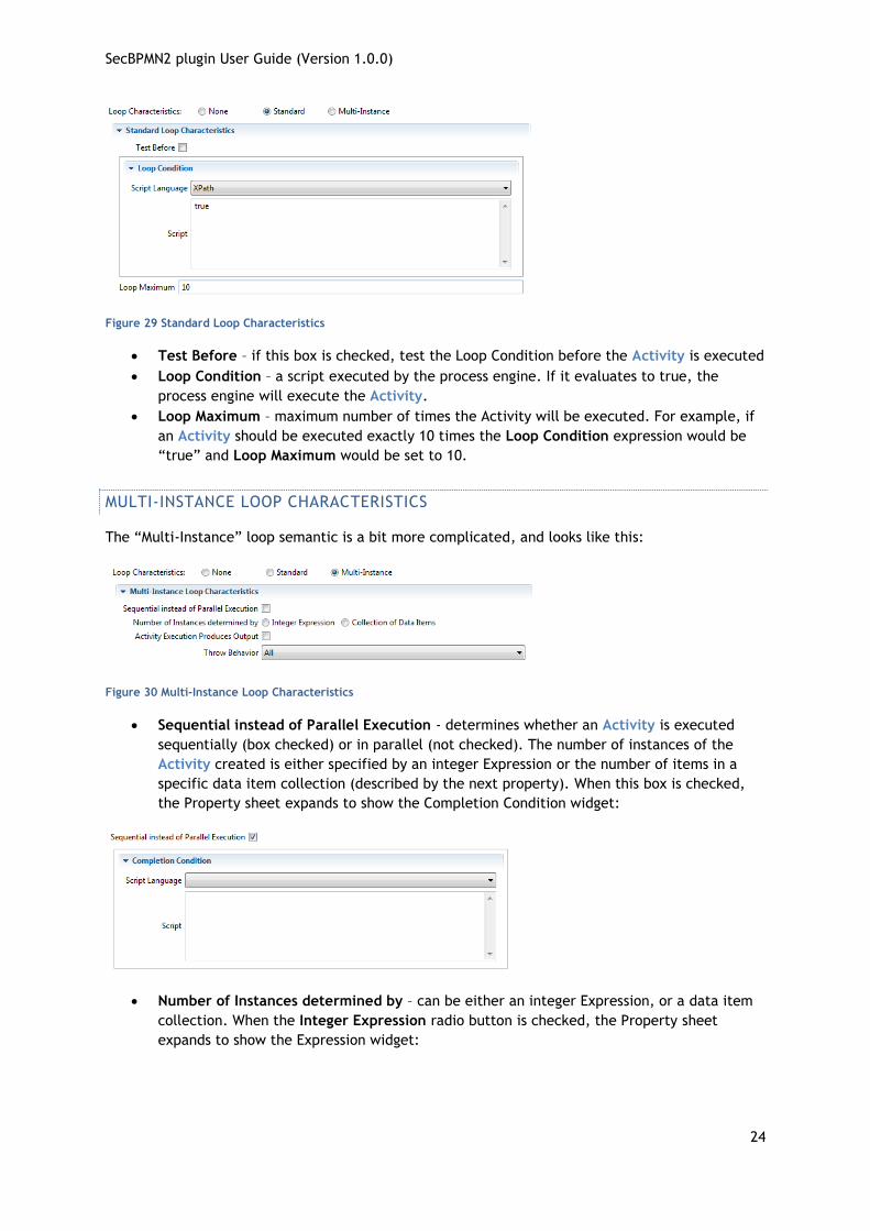
Figure 29 Standard Loop Characteristics
Test Before – if this box is checked, test the Loop Condition before the Activity is executed
Loop Condition – a script executed by the process engine. If it evaluates to true, the
process engine will execute the Activity.
Loop Maximum – maximum number of times the Activity will be executed. For example, if
an Activity should be executed exactly 10 times the Loop Condition expression would be
“true” and Loop Maximum would be set to 10.
MULTI-INSTANCE LOOP CHARACTERISTICS
The “Multi-Instance” loop semantic is a bit more complicated, and looks like this:
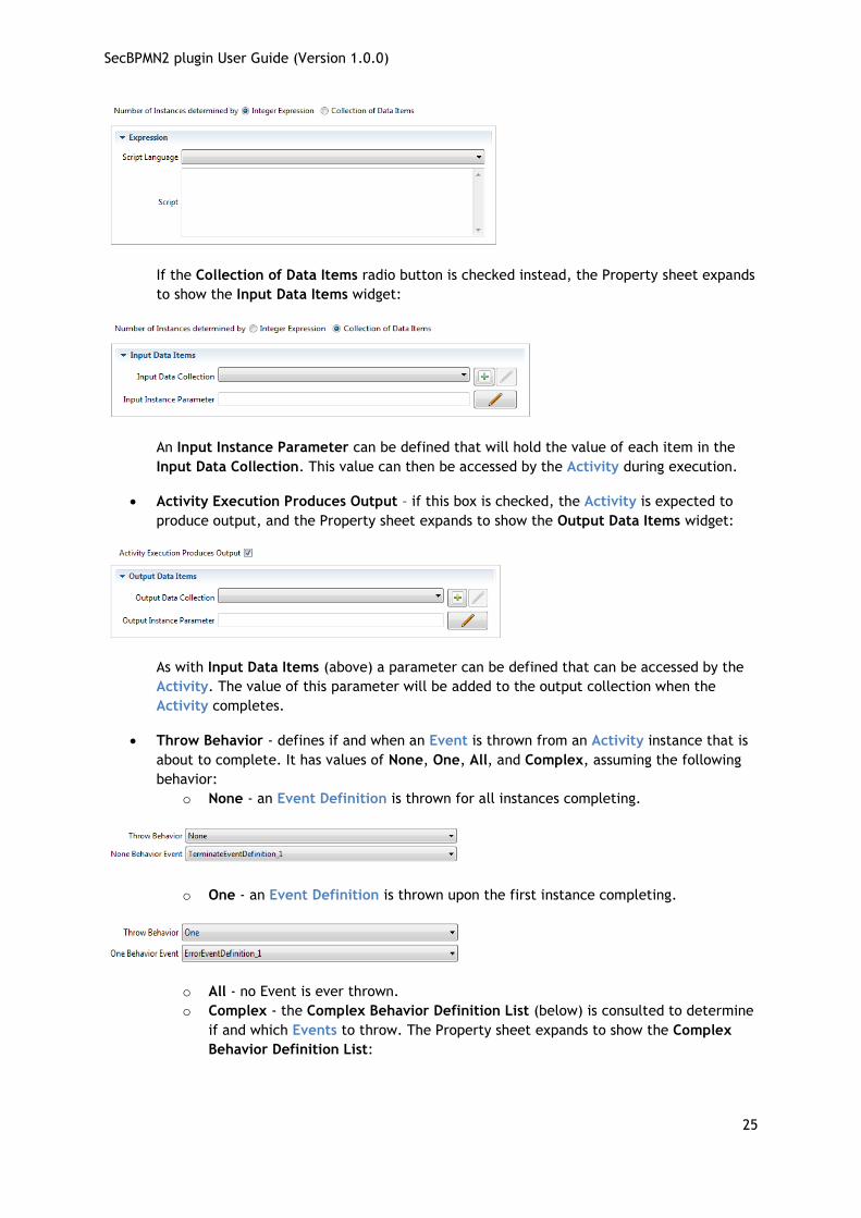
Figure 30 Multi-Instance Loop Characteristics
Sequential instead of Parallel Execution - determines whether an Activity is executed
sequentially (box checked) or in parallel (not checked). The number of instances of the
Activity created is either specified by an integer Expression or the number of items in a
specific data item collection (described by the next property). When this box is checked,
the Property sheet expands to show the Completion Condition widget:
Number of Instances determined by – can be either an integer Expression, or a data item
collection. When the Integer Expression radio button is checked, the Property sheet
expands to show the Expression widget:
SecBPMN2 plugin User Guide (Version 1.0.0)
25
If the Collection of Data Items radio button is checked instead, the Property sheet expands
to show the Input Data Items widget:
An Input Instance Parameter can be defined that will hold the value of each item in the
Input Data Collection. This value can then be accessed by the Activity during execution.
Activity Execution Produces Output – if this box is checked, the Activity is expected to
produce output, and the Property sheet expands to show the Output Data Items widget:
As with Input Data Items (above) a parameter can be defined that can be accessed by the
Activity. The value of this parameter will be added to the output collection when the
Activity completes.
Throw Behavior - defines if and when an Event is thrown from an Activity instance that is
about to complete. It has values of None, One, All, and Complex, assuming the following
behavior:
o None - an Event Definition is thrown for all instances completing.
o One - an Event Definition is thrown upon the first instance completing.
o All - no Event is ever thrown.
o Complex - the Complex Behavior Definition List (below) is consulted to determine
if and which Events to throw. The Property sheet expands to show the Complex
Behavior Definition List:

SecBPMN2 plugin User Guide (Version 1.0.0)
26
Each entry in this List contains a Condition Expression which, if it evaluates to true,
will cause the associated Event to be thrown by the Activity. The details dialog to
edit the Condition Expression and assign a Throw Event is shown below:
I/O PARAMETERS
The I/O Parameters Property tab is used to define the inputs and outputs for an Activity and how
these are associated with (“mapped to”) other data items from the Process that are available to
the Activity. This Property tab contains lists of Input Sets, Input Data Associations (“Mappings”),
Output Sets and Output Data Associations.
See the discussion of Data Associations and Input and Output Sets in the Appendix for more information.
Figure 31 I/O Parameters Tab
When adding or editing an Input Set item, the following details panel is displayed:

SecBPMN2 plugin User Guide (Version 1.0.0)
27
Name – is the Input Set name
Data Inputs - is the list of Data Inputs for the Activity (a.k.a. “Input Parameters”) defined
in the Input Parameter Mapping list
Optional Inputs – is a list of Data Inputs that may be unavailable when the Activity starts
execution
While Executing Inputs – is a list of Data Inputs that can be evaluated while the Activity is
executing
Output Sets – is a list of Output Sets produced by the Activity
Input Parameter Mapping determines how the Input Parameters are filled before the Activity is
executed. Similarly, Output Parameter Mapping determines how data is pulled from Output
Parameters after the Activity has finished.
In the following discussion, only the Input Parameter Mapping will be shown; the behavior of Output
Parameter Mapping is similar except that the “From” and “To” directions are reversed.
The “To” section identifies the Input Parameter, its Data State and Data Type.
The “From” section of the Mapping Details panel identifies the source of the data for the Data
Input:
Variable – the source is a Process Variable, Data Object or Data Store. This data item must
have the same Data Type as the Input Parameter.
Transformation – the transformation expression is executed and must populate the Input
Parameter.
Expression – the Input Parameter is populated by evaluating the Expression.
Assignments – allows for any number of assignment expressions that copy data from any
available data items to the Input Parameter.
The figures below illustrate these different sources.
Variable: here the Process variable “username” is copied to the Input Parameter “greeting”.

SecBPMN2 plugin User Guide (Version 1.0.0)
28
Figure 32 Parameter Mapping Details
Transformation: here an expression is evaluated that transforms source data items to the Data
Type required by the Input Parameter.
Expression: the expression is evaluated and the Input Parameter is populated. This source type is
simply a convenience for an Assignment (see below) that has an expression as the source, and the
Input Parameter as a target. The difference between Expression and Transformation is in their
execution semantics: if a Transformation is specified, any Assignments are ignored.

SecBPMN2 plugin User Guide (Version 1.0.0)
29
Assignments: this allows for multiple source expressions to populate individual elements of the
Input Parameter. Shown here is an Input Parameter “address” being populated with different bits
of information from Process variables.
The Output Sets and Output Parameter Mapping Lists are similar to their input counterparts, but
with the “from” and “to” directions reversed.
SecBPMN2 plugin User Guide (Version 1.0.0)
30
AD HOC SUB-PROCESS
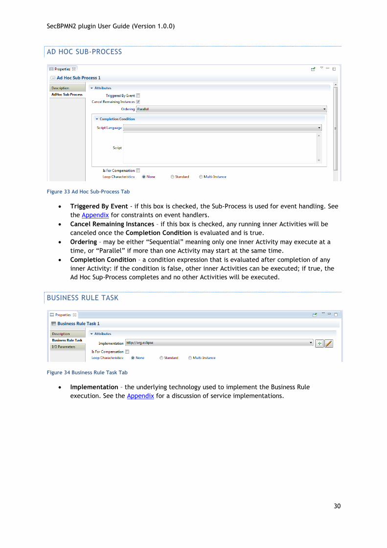
Figure 33 Ad Hoc Sub-Process Tab
Triggered By Event - if this box is checked, the Sub-Process is used for event handling. See
the Appendix for constraints on event handlers.
Cancel Remaining Instances – if this box is checked, any running inner Activities will be
canceled once the Completion Condition is evaluated and is true.
Ordering – may be either “Sequential” meaning only one inner Activity may execute at a
time, or “Parallel” if more than one Activity may start at the same time.
Completion Condition – a condition expression that is evaluated after completion of any
inner Activity: if the condition is false, other inner Activities can be executed; if true, the
Ad Hoc Sup-Process completes and no other Activities will be executed.
BUSINESS RULE TASK
Figure 34 Business Rule Task Tab
Implementation – the underlying technology used to implement the Business Rule
execution. See the Appendix for a discussion of service implementations.

SecBPMN2 plugin User Guide (Version 1.0.0)
31
CALL ACTIVITY
Figure 35 Call Activity Tab
Called Activity – the Activity to be executed. This can be either a Process or Global Task.
RECEIVE TASK
Figure 36 Receive Task Tab
Implementation – the underlying technology implement by the Receive Task. See the
Appendix for a discussion of service implementations.
Operation – the Operation through which the Receive Task receives the Message.
Message – the Message expected by the Receive Task.
Map Incoming Message Data To – I/O Parameter mapping that specifies how the Message
payload is copied to a Process data item.
Instantiate – if this box is checked, this will create a new instance of its containing Process
to handle the Message.
SecBPMN2 plugin User Guide (Version 1.0.0)
32
SCRIPT TASK
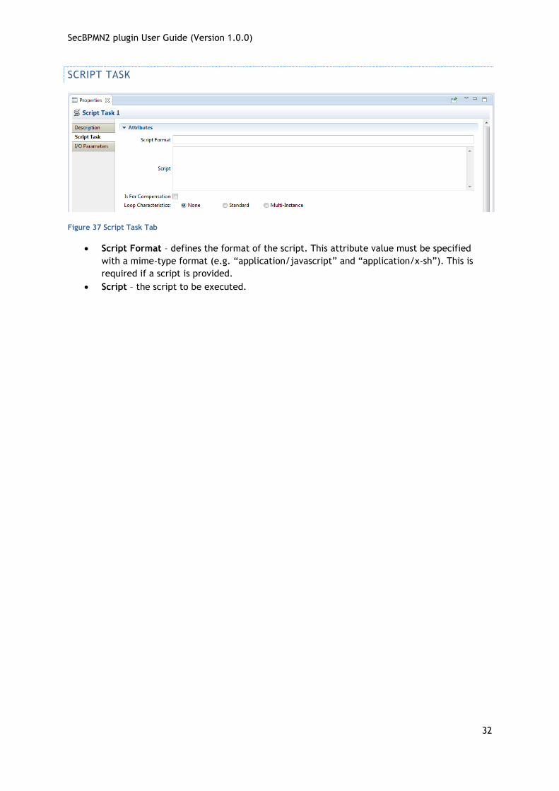
Figure 37 Script Task Tab
Script Format – defines the format of the script. This attribute value must be specified
with a mime-type format (e.g. “application/javascript” and “application/x-sh”). This is
required if a script is provided.
Script – the script to be executed.
SecBPMN2 plugin User Guide (Version 1.0.0)
33
SEND TASK
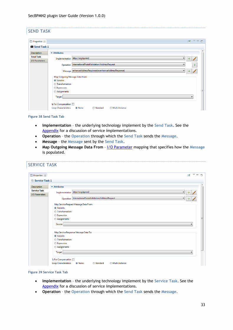
Figure 38 Send Task Tab
Implementation – the underlying technology implement by the Send Task. See the
Appendix for a discussion of service implementations.
Operation – the Operation through which the Send Task sends the Message.
Message – the Message sent by the Send Task.
Map Outgoing Message Data From – I/O Parameter mapping that specifies how the Message
is populated.
SERVICE TASK
Figure 39 Service Task Tab
Implementation – the underlying technology implement by the Service Task. See the
Appendix for a discussion of service implementations.
Operation – the Operation through which the Send Task sends the Message.
SecBPMN2 plugin User Guide (Version 1.0.0)
34
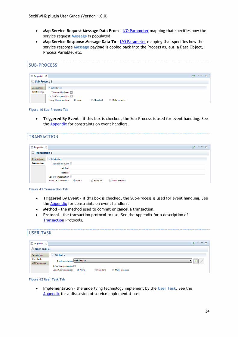
Map Service Request Message Data From – I/O Parameter mapping that specifies how the
service request Message is populated.
Map Service Response Message Data To – I/O Parameter mapping that specifies how the
service response Message payload is copied back into the Process as, e.g. a Data Object,
Process Variable, etc.
SUB-PROCESS
Figure 40 Sub-Process Tab
Triggered By Event - if this box is checked, the Sub-Process is used for event handling. See
the Appendix for constraints on event handlers.
TRANSACTION
Figure 41 Transaction Tab
Triggered By Event - if this box is checked, the Sub-Process is used for event handling. See
the Appendix for constraints on event handlers.
Method - the method used to commit or cancel a transaction.
Protocol - the transaction protocol to use. See the Appendix for a description of
Transaction Protocols.
USER TASK
Figure 42 User Task Tab
Implementation – the underlying technology implement by the User Task. See the
Appendix for a discussion of service implementations.
SecBPMN2 plugin User Guide (Version 1.0.0)
35
GATEWAY
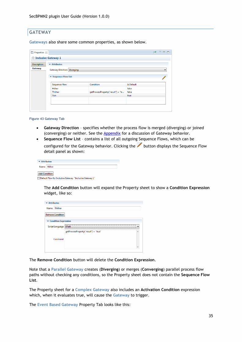
Gateways also share some common properties, as shown below.
Figure 43 Gateway Tab
Gateway Direction – specifies whether the process flow is merged (diverging) or joined
(converging) or neither. See the Appendix for a discussion of Gateway behavior.
Sequence Flow List – contains a list of all outgoing Sequence Flows, which can be
configured for the Gateway behavior. Clicking the button displays the Sequence Flow
detail panel as shown:
The Add Condition button will expand the Property sheet to show a Condition Expression
widget, like so:
The Remove Condition button will delete the Condition Expression.
Note that a Parallel Gateway creates (Diverging) or merges (Converging) parallel process flow
paths without checking any conditions, so the Property sheet does not contain the Sequence Flow
List.
The Property sheet for a Complex Gateway also includes an Activation Condition expression
which, when it evaluates true, will cause the Gateway to trigger.
The Event Based Gateway Property Tab looks like this:

SecBPMN2 plugin User Guide (Version 1.0.0)
36
Please refer to the Appendix for a discussion of Event Based Gateways and the meanings of these properties.
EVENTS
Events come in three flavors: Catching, Throwing and Boundary. The Boundary Event is also a
Catching event, but is attached to an Activity. All Event types have an Event Definitions List as
shown below:
Figure 44 Event Tab
Event Definitions determine the behavior of the Event. There are ten different types of Event
Definitions but not all of them apply to all types of Events.
Please see the Appendix for a discussion of Events and Event Definitions.
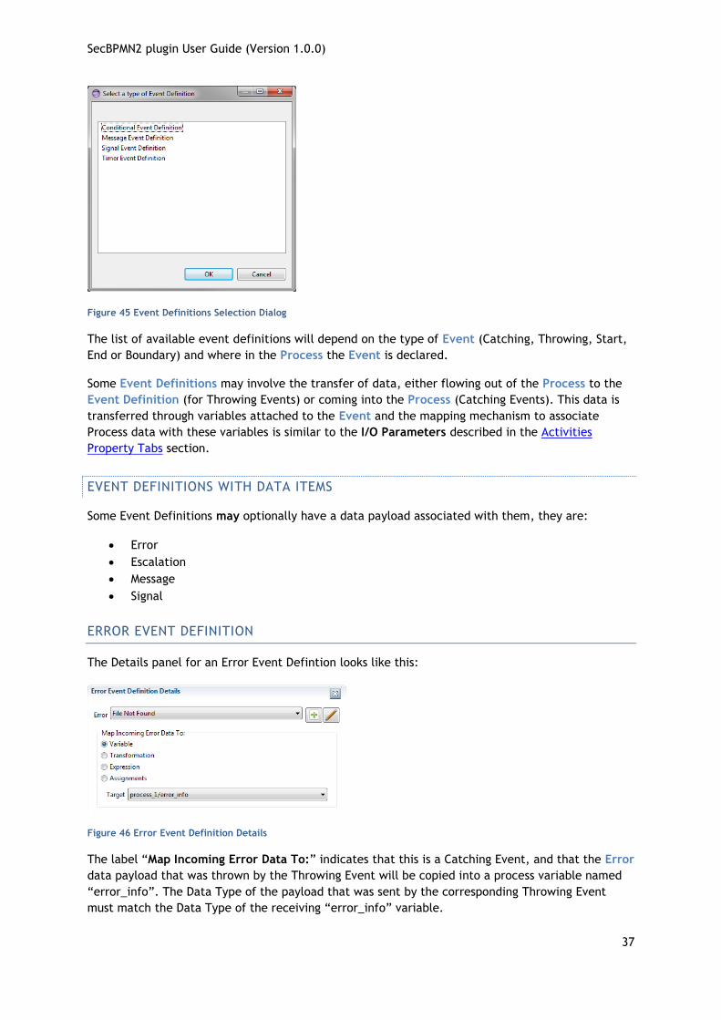
Clicking the button in the Event Definitions List displays the Event Definition selection dialog:
SecBPMN2 plugin User Guide (Version 1.0.0)
37
Figure 45 Event Definitions Selection Dialog
The list of available event definitions will depend on the type of Event (Catching, Throwing, Start,
End or Boundary) and where in the Process the Event is declared.
Some Event Definitions may involve the transfer of data, either flowing out of the Process to the
Event Definition (for Throwing Events) or coming into the Process (Catching Events). This data is
transferred through variables attached to the Event and the mapping mechanism to associate
Process data with these variables is similar to the I/O Parameters described in the Activities
Property Tabs section.
EVENT DEFINITIONS WITH DATA ITEMS
Some Event Definitions may optionally have a data payload associated with them, they are:
Error
Escalation
Message
Signal
ERROR EVENT DEFINITION
The Details panel for an Error Event Defintion looks like this:
Figure 46 Error Event Definition Details
The label “Map Incoming Error Data To:” indicates that this is a Catching Event, and that the Error
data payload that was thrown by the Throwing Event will be copied into a process variable named
“error_info”. The Data Type of the payload that was sent by the corresponding Throwing Event
must match the Data Type of the receiving “error_info” variable.

SecBPMN2 plugin User Guide (Version 1.0.0)
38
ESCALATION EVENT DEFINITION
The Details panel for an Escalation Event Definition is similar:
Figure 47 Escalation Event Definition Details
Here the Event is a Throwing Event (“Map Outgoing Escalation Data From:”) and in this example,
an Expression is used to populate a variable in the Event. The payload (a String in this case) will be
passed to the Catching Event triggered by this Throwing Event.
MESSAGE EVENT DEFINITION
Message Event Definitions require a message identified by either an Operation/Message pair, or
just a Message defined within the Process:
Figure 48 Message Event Definition Details
In this example, the contents of the process variable “addressRequest” will be copied to the Event
variable and transferred to the Catching Event that is triggered by this Throwing Event. The
“addressRequest” Data Type must be the same as the Message. The Catching Event must specify
the same message type in its Message Event Definition.

SecBPMN2 plugin User Guide (Version 1.0.0)
39
SIGNAL EVENT DEFINITION
This is similar to the Error and Escalation Event Definitions:
Figure 49 Signal Event Definition Details
DATA ITEMS
Data Items fall in to three categories:
Data Objects
Data Inputs and Outputs
Data Stores
The Property Tabs for these are very similar and all define a Data Type and Data State. The Is
Collection check box indicates the data item is a collection of objects:
Figure 50 Data Object Tab
Data Objects and Data Stores are reusable entities, thus we can have multiple visual
representations of the same data instance on the Drawing Canvas. These are known as
“References” to the original and have an additional Reference tab:
A Reference may be in a different Data State than the original object, as shown above.
Data Stores may also specify a fixed capacity, or may be “unlimited” in size:

SecBPMN2 plugin User Guide (Version 1.0.0)
40
SEQUENCE FLOWS
The Sequence Flow Property Tab allows an optional condition expression to be added to the
Sequence Flow as shown here:
Figure 51Sequence Flow Tab
See also the Property Tab for Gateways.
SECURITY ANNOTATIONS
The Security Annotations Property Tab is used to specify security properties. Since the type of
security properties that can be edited for each security annotation change with the linked element,
is possible to modify security properties only after the security annotation has been associated to
another SecBPMN2 element. See Error! Reference source not found. section for discussion on
ecurity annotations.
In all security annotation is possible to specify the EnfBy security property, which is a list of
security controls that will enforce the security annotation in the implementation, for further
information refer to [3].
In the following all security properties, of each security annotation, enlisted and explained
ACCOUNTABILITY
The security property Monitored can be specified only for tasks. It specifies the list of users, which
are monitored.
SecBPMN2 plugin User Guide (Version 1.0.0)
41
AUDITABILITY
The security property Frequency can be specified for tasks, data objects and message flows. It
specifies how often the security checks are performed. If frequency is set to zero, continuous
verification is required.
AUTHENTICITY
The security property Identification can be specified only for tasks. It is a Boolean variable that,
if true, specifies that anonymous users should not take part in the execution of the activity.
The security property Authentication can be specified only for tasks. It is a Boolean variable that, if
true, specifies that the identity of users should be verified.
The security property trustValue, can be specified only for tasks. It specifies the minimum level of
trust the executor of activity a must have.
AVAILABILITY
The security property authUsers, can be specified for tasks, data objects and message flows. It
specifies the user that can access the resource. With the keyword ALL it specifies that all users are
authorized to request the data object.
The security property Level can be specified for tasks, data objects and message flows. It specifies
the minimum time percentage that the resource (i.e., activity, data object or message flow,
depending on the variant of availability annotation) should be available.
CONFIDENTIALITY
The security property Readers can be specified for data objects and message flows. It specifies the
set of users that are authorized to read the data object (or receive from the message flow).
The security property Writers can be specified for data objects and message flows. It specifies the
set of users that are authorized to write the data object do (or send through the message flow).
INTEGRITY
The security property Personnel can be specified only for tasks. It is a Boolean variable that, if
true, specifies that the personnel, who executes the task, shall be protected from intentional
corruption.
The security property Hardware can be specified only for tasks. It is a Boolean variable that, if true,
specifies that the hardware, used to execute the task, shall be protected from intentional
corruption.
The security property Software can be specified only for tasks. It is a Boolean variable that, if true,
specifies that the software, used to execute the task, shall be protected from intentional
corruption.

SecBPMN2 plugin User Guide (Version 1.0.0)
42
NON-REPUDIATION
The security property Execution can be specified for tasks and message flows. It is a Boolean
variable that specifies: (i) a proof of execution of the task or a proof of usage of the message flow
shall be provided, if set to true; (ii) a proof of non-execution for the task or a proof of non-usage
for the message flow shall be provided, if set to false.
PRIVACY
The security property SensitiveInfo can be specified for tasks and data objects. It specifies the set
of sensitive information to protect.
SEPARATION OF DUTY
The security property Dynamic can be specified only for participants. It is a Boolean variable that, if
true, specifies that the set of people, which play the role specified in the participant, change
during the execution of the system.
BIND OF DUTY
The security property Dynamic can be specified only for participants. It is a Boolean variable that, if
true, specifies that the set of people, which play the role specified in the participant, change
during the execution of the system.
NON DELEGATION
Only EnfBy security property can be specified for non-delegation.
MAPPING VIEW
Is possible to map STS-ml elements with SecBPMN2 elements, in order to connect the two models
and verify the enforcement of security needs specified in STS-ml are enforced in SecBPMN2. When a
business process is generated from an STS-ml model, some of its elements are automatically
mapped to STS-ml elements.
The mapping view shows such mapping and permits to modify it. When a SecBPMN2 model is open
the mapping view is situated in the property pane, as shown in Figure 52. The mappable elements
are organized by business process diagram. Each pool contains one process and zero or more data
objects. Messages are not linked to pools and, therefore, are shown at the same level of pools.
Figure 52 Mapping View

SecBPMN2 plugin User Guide (Version 1.0.0)
43
To manage the mapping for an element, right click on the element in the mapping view and clink
on Manage mapping in the contextual menu, as shown in Figure 53. This action will show the BPMN to
STS Mapping dialog as shown in Figure 54. The elements on the left list are the elements that can be
mapped, while the list on the right shows the elements that are mapped. To move elements
between lists, select the element and click the buttons between the lists, or double click the
elements.
Figure 53 Mapping View Context Menu
Figure 54 BPMN to STS Mapping Dialog
Table 1 shows the mapping between STS-ml and SecBPMN2 elements.
STS-ml element SecBPMN2 element
Agent Role
Participant Lane
Document Data Object
Message
Goal
Process
Delegation
Transmission
Read
Modify
Produce
Table 1: mapping between STS-ml and SecBPMN2
OUTLINE VIEW
The Outline has three different views of the file; these views are selected using the toolbar buttons
at the top of the viewer window:
Figure 55 Outline Viewer Title Bar Buttons

SecBPMN2 plugin User Guide (Version 1.0.0)
44
Business Model View – this roughly corresponds to the graphical elements on the drawing
canvas, but also includes model elements that do not necessarily have a visual representation
such as Data Types, Interfaces, Operations, Process variables and so on.
Diagram Interchange Model – this displays the DI model, which is that part of the spec that
defines visual presentation details such as locations and sizes of shapes, connection bend
points, labels, etc. This view is useful for visualizing the graphical elements and their
relationships and containments.
Thumbnail – this is simply a small overview of the entire diagram scaled to fit into the
Outline View window.
The following screenshots show an example business process diagram and how each of the views of
the Outline is rendered.
Figure 56 Sample Process
Figure 57 Business Model
Figure 58 DI Model
Figure 59 Thumbnail
POPUP DIALOGS
Popup dialogs are used throughout the editor to prompt for additional configuration information or
command confirmation. This section describes some the more “interesting” of these dialogs.
BPMN2 ELEMENT PROPERTY DIALOGS
As described in the section on Graphical Editing, you do have the option of closing the Property
Viewer and using popup dialogs to configure the elements. In this case, the property tabs are laid

SecBPMN2 plugin User Guide (Version 1.0.0)
45
out horizontally in a popup dialog, instead of vertically (as in the Property View). Also, the
Description tab is omitted to save space.
Like the Property View, the content of the Property Dialog varies, depending on which element is
being edited. Here is an example of the Property Dialog showing the settings for a Manual Task:
Figure 60 SecBPMN2 Element Property Dialogs
As a shortcut to speed configuration of SecBPMN2 elements, you can configure the editor to have the Property Dialog pop up automatically when
an element is dragged onto the Drawing Canvas from the Tool Palette.
DATA TYPE DIALOG
Data Types (a.k.a. “Item Definitions”) use the following configuration dialog:
Figure 61 Data Type (“Item Definition”) Editing Dialog
Item Kind – indicates whether the item is Physical or Informational
Is Collection – if checked, the item represents a collection of data
Structure – a reference to the actual structure of the data. By default, this is an XSD type,
but may also be other language data types (e.g. Java) depending on the Type System
defined for the Process.
VARIABLE DIALOG
Variables (a.k.a. “Properties”) are configured with the following dialog:

SecBPMN2 plugin User Guide (Version 1.0.0)
46
Figure 62 Variable ("Property") Editing Dialog
Name – the variable name
Data State – an application-defined state such as “initialized” or “staging”. See also Data
Elements.
Data Type – the type and structure of the variable (see above)
MESSAGE DIALOG
Messages are configured with the following dialog:
Figure 63 Message Editing Dialog
Name – the name of the Message
Data Type – the type and structure of the Message payload
ERROR DIALOG
Errors are configured with the following dialog:
Figure 64 Error Editing Dialog
Name – the name of the Error

SecBPMN2 plugin User Guide (Version 1.0.0)
47
Error Code – an application-specific value that can be used by Activities in, e.g. condition
expressions to test for specific error types
Data Type – the type and structure of the Error payload (if any)
SIGNAL DIALOG
Signals are configured with the following dialog:
Figure 65 Signal Editing Dialog
Name – the name of the Signal
Data Type – the type and structure of the Signal payload (if any)
ESCALATION DIALOG
Escalations are configured with the following dialog:
Figure 66 Escalation Editing Dialog
Name – the name of the Escalation
Error Code – an application-specific value that can be used by Activities in, e.g. condition
expressions to test for specific escalation types
Data Type – the type and structure of the Escalation payload (if any)
DATA STORE DIALOG
Data Stores are configured with the following dialog:

SecBPMN2 plugin User Guide (Version 1.0.0)
48
Figure 67 Data Store Editing Dialog
Name – the name of the Data Store. This is typically a database table or file name,
depending on the underlying technology used to persist the data.
Capacity – an application-specific value that represents the maximum capacity of the Data
Store
Is Unlimited – if checked, indicates the Data Store capacity is unlimited. This overrides the
Capacity value.
Data Type – the type and structure of the Data Store
Data State – an application-specific state of the data, e.g. “committed”, “archived”, etc.
See also Data Elements.
IMPORT EDITING DIALOG
Editing an imported file from the Imports List in the Process Definitions property tab displays the
following dialog:
Figure 68 Import Editing Dialog
Note that only the Prefix can be edited, all other fields are read-only. Clicking the button
displays this dialog which allows you to select a namespace prefix:
Figure 69 Namespace Editing Dialog
SecBPMN2 plugin User Guide (Version 1.0.0)
49
The editor will check to ensure that the new prefix is not already in use.
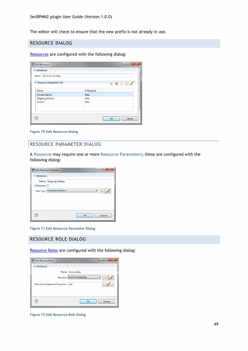
RESOURCE DIALOG
Resources are configured with the following dialog:
Figure 70 Edit Resource Dialog
RESOURCE PARAMETER DIALOG
A Resource may require one or more Resource Parameters; these are configured with the
following dialog:
Figure 71 Edit Resource Parameter Dialog
RESOURCE ROLE DIALOG
Resource Roles are configured with the following dialog:
Figure 72 Edit Resource Role Dialog

SecBPMN2 plugin User Guide (Version 1.0.0)
50
EXPORT DIAGRAM DIALOG
This dialog is invoked from the Drawing Canvas context menu. It is used to save the currently
selected diagram as an image file. The image can be saved in several different formats and sizes.
Figure 73 Export Diagram Dialog
USER PREFERENCES
The SecBPMN2 plugin appearance and behavior can be customized from Eclipse Preferences
settings. To access the Preferences dialog, from the main menu click Window -> Settings then
select the SecBPMN2 category from the tree in the left of the dialog (see below).
The SecBPMN2 plugin Preferences are divided into three general categories: General Settings,
Editor Setting, and settings contributed by extension plug-ins. The Editor Settings are further
divided into Appearance, Behavior and Tool Profiles.
Some of these settings may require a restart of the editor to take effect (i.e. closing and reopening the editor, not the Eclipse workbench!)
GENERAL SETTINGS
These settings are related to the SecBPMN2 model itself and affect how imported files are treated.
Default values for BPMN DI optional attributes settings determine the values of optional SecBPMN2
attributes; possible selections are:
True if not set – the attribute will be forced to TRUE if it is missing from the file being
imported.
False if not set – the attribute will be forced to FALSE if it is missing from the file being
imported.
Always True – the attribute will always be forced to TRUE, even if it is set in the file being
imported.
Always False – the attribute will always be forced to FALSE, even if it is set in the file
being imported.
The result for each of these attributes will be either TRUE or FALSE; these have the following
meanings:
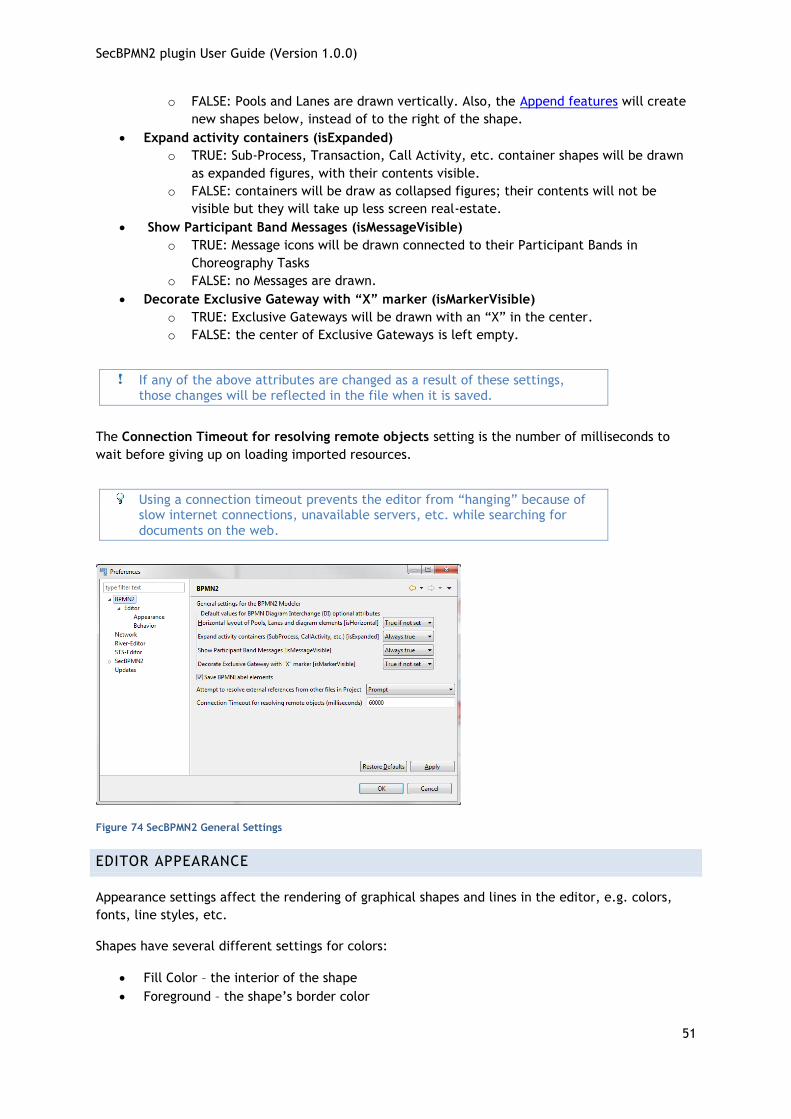
Horizontal layout of Pools, Lanes and diagram elements (isHorizontal)
o TRUE: Pools and Lanes will be drawn horizontally.
SecBPMN2 plugin User Guide (Version 1.0.0)
51
o FALSE: Pools and Lanes are drawn vertically. Also, the Append features will create
new shapes below, instead of to the right of the shape.
Expand activity containers (isExpanded)
o TRUE: Sub-Process, Transaction, Call Activity, etc. container shapes will be drawn
as expanded figures, with their contents visible.
o FALSE: containers will be draw as collapsed figures; their contents will not be
visible but they will take up less screen real-estate.
Show Participant Band Messages (isMessageVisible)
o TRUE: Message icons will be drawn connected to their Participant Bands in
Choreography Tasks
o FALSE: no Messages are drawn.
Decorate Exclusive Gateway with “X” marker (isMarkerVisible)
o TRUE: Exclusive Gateways will be drawn with an “X” in the center.
o FALSE: the center of Exclusive Gateways is left empty.
If any of the above attributes are changed as a result of these settings, those changes will be reflected in the file when it is saved.
The Connection Timeout for resolving remote objects setting is the number of milliseconds to
wait before giving up on loading imported resources.
Using a connection timeout prevents the editor from “hanging” because of slow internet connections, unavailable servers, etc. while searching for
documents on the web.
Figure 74 SecBPMN2 General Settings
EDITOR APPEARANCE
Appearance settings affect the rendering of graphical shapes and lines in the editor, e.g. colors,
fonts, line styles, etc.
Shapes have several different settings for colors:
Fill Color – the interior of the shape
Foreground – the shape’s border color

SecBPMN2 plugin User Guide (Version 1.0.0)
52
Selected – the fill color when the shape is the primary selection
Multi-Selected – fill color when the shape is one of several selected shapes, but not the
primary selection
Labels also have a color setting as well as a font style and size.
The Override shape size with default values setting can be used to normalize unusually large or
small shapes in a file being imported.
Figure 75 Editor Appearance (Shapes)
Connection lines only have a foreground color, but their labels may also have a different color and
font.
The Routing Style setting determines how connection lines are routed from source to target:
Manual Bendpoint – the line is drawn directly from source to target; if a shape is moved so
that it “collides” with the connection line, the editor does not attempt to reroute the
connection. Also, manual bendpoints are not relocated. See the Graphical Editing section
for an explanation of bendpoints.
Automatic Bendpoint – the line is drawn directly from source to target; the editor
attempts to reroute connections around shapes so that they do not collide with the shape.
Also, manual bendpoints are not relocated.
Manhattan – connections are drawn as a series of horizontal and vertical line segments
from source to target (reminiscent of the Manhattan skyline.) Bendpoints are automatically
relocated as necessary.

SecBPMN2 plugin User Guide (Version 1.0.0)
53
Figure 76 Editor Appearance (Connections)
EDITOR BEHAVIOR
These settings have the following meanings:
Show Advanced Properties Tab – displays an optional “Advanced” tab in the Property
View.
Show descriptions – displays descriptive information about each selected element in the
“Description” tab of the Property View.
Show ID attribute – displays the ID attribute for selected elements.
Use a popup dialog instead of Details Panel to edit List items – by default, the List and
Details Property widget will use a sliding Detail Panel to edit a List item. Setting this
checkbox will display the Details in a popup dialog instead.
Display element configuration popup dialog – this causes the Property Configuration Dialog
to automatically pop up whenever a new element is dropped on the Drawing Canvas.
Editing ID attributes should be used with caution! IDs are considered “internal” data and may cause the file to become corrupted if duplicate IDs
are created inadvertently.
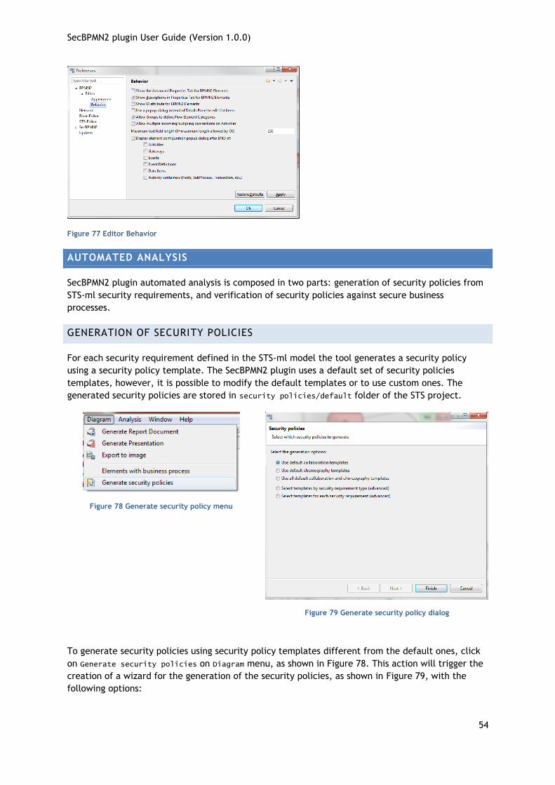
SecBPMN2 plugin User Guide (Version 1.0.0)
54
Figure 77 Editor Behavior
AUTOMATED ANALYSIS
SecBPMN2 plugin automated analysis is composed in two parts: generation of security policies from
STS-ml security requirements, and verification of security policies against secure business
processes.
GENERATION OF SECURITY POLICIES
For each security requirement defined in the STS-ml model the tool generates a security policy
using a security policy template. The SecBPMN2 plugin uses a default set of security policies
templates, however, it is possible to modify the default templates or to use custom ones. The
generated security policies are stored in security policies/default folder of the STS project.
Figure 78 Generate security policy menu
Figure 79 Generate security policy dialog
To generate security policies using security policy templates different from the default ones, click
on Generate security policies on Diagram menu, as shown in Figure 78. This action will trigger the
creation of a wizard for the generation of the security policies, as shown in Figure 79, with the
following options:

SecBPMN2 plugin User Guide (Version 1.0.0)
55
With the first option the wizard will generate a set of security policies using the default
templates for the collaboration models
With the second option the wizard will generate a set of security policies using the default
templates for the choreography models
With the third option the wizard will generate a set of security policies using the default
templates for both the collaboration and choreography models
The forth options permits to choose which security policy template to use for the
generation of security policies, for each type of security requirements. Figure 80 shows the
part of the wizard that permits to choose the security policy template. The first column
shows the STS-ml security requirement, the second column the security policy templates
chosen for the collaboration models, while the third column the security policy template
chosen for the choreography models. To select a different template, click on the small
arrow near the cell to be updated, and select from the list the security policy template
that will be used for the generation. To skip the generation of the security policy for a
security requirement, select none from the list.
The fifth option permits to select which security policy template to use for each STS-ml
security requirements. The first column shows the STS-ml security requirements, the
second column shows the security policy template chosen for collaboration model, while
the third column shows the security policy templates chosen for choreography models.
Figure 81 shows the wizard for this type of selection.
Figure 80 Generate security policy by Security
Requirement by type
Figure 81 Generate security policy by Security
Requirement
VERIFICATION OF SECURITY POLICIES
STS-tool permits to automatically verify security policies against secure business processes. Once
the business processes are defined, open the STS-ml model and click on Security enforcement
analysis under the Analysis Menu, as shown in . To start the analysis, click on Run Analysis button.
The analysis verify all the security policies contained in the STS project folder security policies.
Such folder contains two subfolders: default, which contains the security policies generated
automatically, and user, which contained security policies defined by the users. It is not possible to
modify security policies that are inside the folder default, therefore, they have to be moved (with
copy and paste commands from the project view) in the user folder.

SecBPMN2 plugin User Guide (Version 1.0.0)
56
The security policies in the default folder will be replaced by a new set of
security policies, every time the generation function is called.
Figure 82 Launch Security Enforcement Analysis
A pop-up window will show the outcomes of each step, as shown in . Once the second step is
completed, click on “Done” button to close the pop-up window and visualize the results of the
analysis.
Figure 83 Security Enforcement Analysis Dialog
When the analysis is completed, click on the Done button to visualize the results of the analysis.
Figure 84 Analysis results
The results are shown in the Analysis results tab of the property pane, as shown in Figure 84.
Each row corresponds on a security policy. The left column described the outcome of the security
policy, the right column the task executed. A double click on a row will highlight in red, on the STS-
ml model, the elements that caused the violation of the security policy. Another double-click on
the same row will hide the highlight.
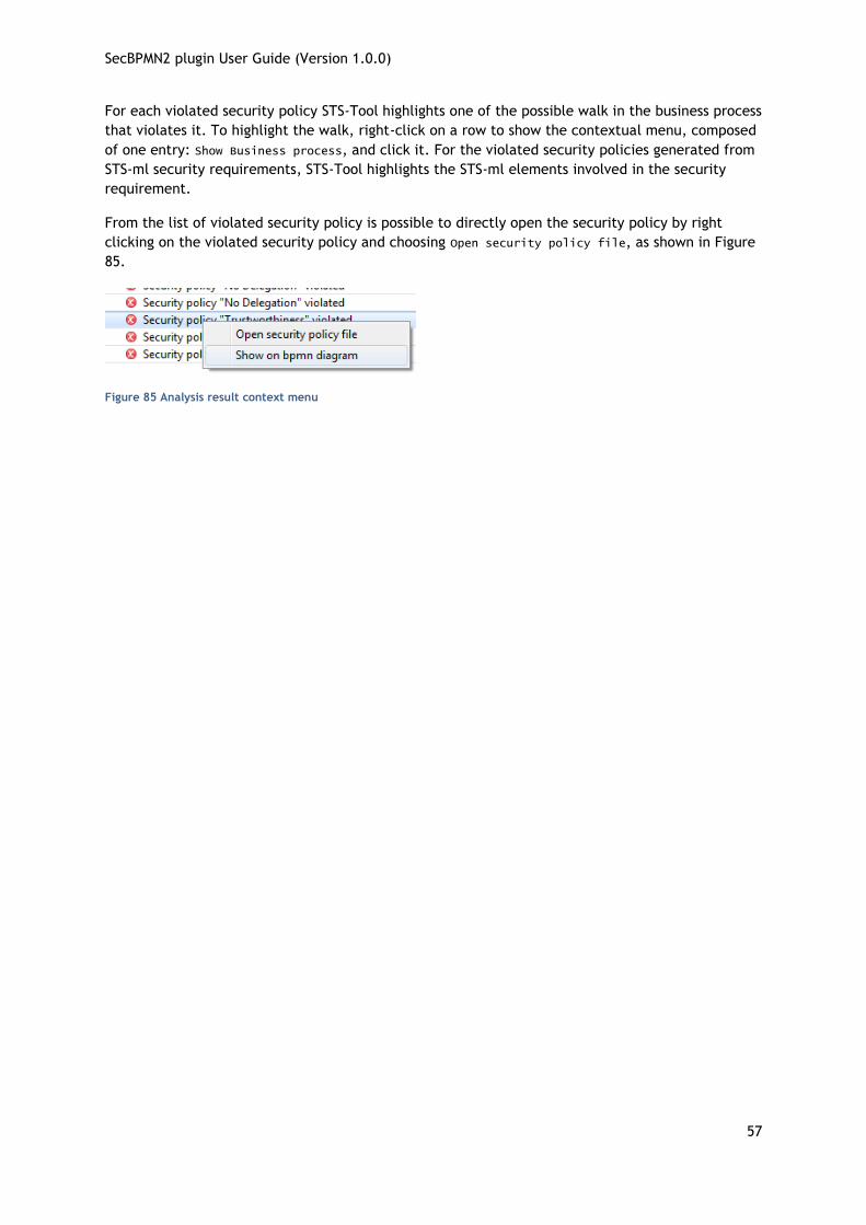
SecBPMN2 plugin User Guide (Version 1.0.0)
57
For each violated security policy STS-Tool highlights one of the possible walk in the business process
that violates it. To highlight the walk, right-click on a row to show the contextual menu, composed
of one entry: Show Business process, and click it. For the violated security policies generated from
STS-ml security requirements, STS-Tool highlights the STS-ml elements involved in the security
requirement.
From the list of violated security policy is possible to directly open the security policy by right
clicking on the violated security policy and choosing Open security policy file, as shown in Figure
85.
Figure 85 Analysis result context menu

SecBPMN2 plugin User Guide (Version 1.0.0)
58
FIGURES AND TABLES
Figure 1 Install software menu ..................................................................................... 2
Figure 2 Install Software Wizard Dialog .......................................................................... 2
Figure 3 Secure Business Process Editor .......................................................................... 3
Figure 4 Disable validation ......................................................................................... 3
Figure 5 Security Policy Editor ..................................................................................... 4
Figure 6 Secure Business Process Template Editor ............................................................. 5
Figure 7 Security Policy Template Editor ........................................................................ 6
Figure 8 Create Business Process for STS Diagram ............................................................. 6
Figure 9 Edit / Delete Business Process for STS Diagram ...................................................... 6
Figure 10 Delete diagram confirm dialog ........................................................................ 7
Figure 11 Jump to Business Process ............................................................................... 7
Figure 12 Jump to STS Diagram .................................................................................... 7
Figure 13 Add module context menu ............................................................................. 8
Figure 14 Add Module Wizard ...................................................................................... 8
Figure 15 New SecBPMN2 File ...................................................................................... 8
Figure 16 SecBPMN2 Editor multiple Diagrams .................................................................. 9
Figure 17 XML Source View ......................................................................................... 9
Figure 18 Tool Palette .............................................................................................. 11
Figure 19 Tool Palette Configuration ............................................................................ 12
Figure 20 Context Button Pad ..................................................................................... 12
Figure 21 Tabbed Property View .................................................................................. 15
Figure 22 List and Detail widget in normal and expanded views ........................................... 16
Figure 23 Nested List and Detail widgets ....................................................................... 16
Figure 24 Process Tab .............................................................................................. 17
Figure 25 Interfaces Tab ........................................................................................... 18
Figure 26 Definitions Tab .......................................................................................... 19
Figure 27 Data Items Tab .......................................................................................... 22
Figure 28 Manual Task Tab ......................................................................................... 23

SecBPMN2 plugin User Guide (Version 1.0.0)
59
Figure 29 Standard Loop Characteristics ........................................................................ 24
Figure 30 Multi-Instance Loop Characteristics ................................................................. 24
Figure 31 I/O Parameters Tab ..................................................................................... 26
Figure 32 Parameter Mapping Details ............................................................................ 28
Figure 33 Ad Hoc Sub-Process Tab ............................................................................... 30
Figure 34 Business Rule Task Tab ................................................................................. 30
Figure 35 Call Activity Tab ......................................................................................... 31
Figure 36 Receive Task Tab ........................................................................................ 31
Figure 37 Script Task Tab .......................................................................................... 32
Figure 38 Send Task Tab ........................................................................................... 33
Figure 39 Service Task Tab ........................................................................................ 33
Figure 40 Sub-Process Tab ......................................................................................... 34
Figure 41 Transaction Tab ......................................................................................... 34
Figure 42 User Task Tab ............................................................................................ 34
Figure 43 Gateway Tab ............................................................................................. 35
Figure 44 Event Tab ................................................................................................. 36
Figure 45 Event Definitions Selection Dialog ................................................................... 37
Figure 46 Error Event Definition Details ......................................................................... 37
Figure 47 Escalation Event Definition Details .................................................................. 38
Figure 48 Message Event Definition Details ..................................................................... 38
Figure 49 Signal Event Definition Details ........................................................................ 39
Figure 50 Data Object Tab ......................................................................................... 39
Figure 51Sequence Flow Tab ...................................................................................... 40
Figure 52 Mapping View ............................................................................................ 42
Figure 53 Mapping View Context Menu .......................................................................... 43
Figure 54 BPMN to STS Mapping Dialog .......................................................................... 43
Figure 55 Outline Viewer Title Bar Buttons ..................................................................... 43
Figure 56 Sample Process .......................................................................................... 44
Figure 57 Business Model ........................................................................................... 44
Figure 58 DI Model................................................................................................... 44

SecBPMN2 plugin User Guide (Version 1.0.0)
60
Figure 59 Thumbnail ................................................................................................ 44
Figure 60 SecBPMN2 Element Property Dialogs ................................................................ 45
Figure 61 Data Type (“Item Definition”) Editing Dialog ...................................................... 45
Figure 62 Variable ("Property") Editing Dialog ................................................................. 46
Figure 63 Message Editing Dialog ................................................................................. 46
Figure 64 Error Editing Dialog ..................................................................................... 46
Figure 65 Signal Editing Dialog .................................................................................... 47
Figure 66 Escalation Editing Dialog ............................................................................... 47
Figure 67 Data Store Editing Dialog .............................................................................. 48
Figure 68 Import Editing Dialog ................................................................................... 48
Figure 69 Namespace Editing Dialog ............................................................................. 48
Figure 70 Edit Resource Dialog .................................................................................... 49
Figure 71 Edit Resource Parameter Dialog ...................................................................... 49
Figure 72 Edit Resource Role Dialog ............................................................................. 49
Figure 73 Export Diagram Dialog.................................................................................. 50
Figure 74 SecBPMN2 General Settings ........................................................................... 51
Figure 75 Editor Appearance (Shapes) ........................................................................... 52
Figure 76 Editor Appearance (Connections) .................................................................... 53
Figure 77 Editor Behavior .......................................................................................... 54
Figure 78 Generate security policy menu ....................................................................... 54
Figure 79 Generate security policy dialog ...................................................................... 54
Figure 80 Generate security policy by Security Requirement by type ..................................... 55
Figure 81 Generate security policy by Security Requirement ............................................... 55
Figure 82 Launch Security Enforcement Analysis .............................................................. 56
Figure 83 Security Enforcement Analysis Dialog ............................................................... 56
Figure 84 Analysis results .......................................................................................... 56
Figure 85 Analysis result context menu ......................................................................... 57
Table 1: mapping between STS-ml and SecBPMN2 ............................................................ 43

SecBPMN2 plugin User Guide (Version 1.0.0)
61
REFERENCES
[1] M. Salnitri, E. Paja and P. Giorgini, "Mantaining Secure Business Processes in Light of Socio-
Technical Systems' Evolution," To Appear, p. 14, 2016.
[2] M. Salnitri, E. Paja and P. Giorgini, "Preserving Compliance with Security Requirements in
Socio-Technical Systems," Proceeding of Cyber Security and Privacy (CSP) forum, 2014.
[3] M. Salnitri, F. Dalpiaz and P. Giorgini, "Designing Secure Business Processes with SecBPMN,"
International Journal on Software and Systems Modeling, p. 26, 2016.
[4] J. Freund and B. Rücker, Real Life BPMN, Berlin: Camunda, 2012.
[5] T. Allweyer, BPMN 2.0 - Introduction to the Standard for Business Process Modeling, Books on
Demand GmbH, Norderstedt, 2010.
[6] P. Brittenham, "An overview of the Web Services Inspection Language," IBM, 1 6 2002. [Online].
Available: http://www.ibm.com/developerworks/webservices/library/ws-wsilover/.
[7] "Business Process Simulation Interchange Standard," BPSim.org, [Online]. Available:
http://www.bpsim.org/.
[8] "Business Process Model and Notation (BPMN)," OMG, 1 2011. [Online]. Available:
http://www.omg.org/spec/BPMN/2.0/.
[9] "Eclipse BPMN2," [Online]. Available:
http://www.eclipse.org/modeling/mdt/?project=bpmn2#bpmn2.
[10] "jBPM Documentation Library," JBoss/Red Hat, [Online]. Available:
http://www.jboss.org/jbpm/documentation.