section3 2terminal characteristics of junction diodesjstiles/312/handouts/section3_2terminal... ·...
TRANSCRIPT

1/29/2008 section3_2Terminal_Characteristics_of_Junction_Diodes.doc 1/6
Jim Stiles The Univ. of Kansas Dept. of EECS
3.2 Terminal Characteristics of Junction Diodes (pp.147-153)
A Junction Diode – I.E., A “real” diode! Similar to an ideal diode, its circuit symbol is:
HO: The Junction Diode Curve HO: The Junction Diode Equation A. The Forward Bias Region Consider when D Tv nV (i.e, when 25Dv mV≈ ).
Dv+ −
Di

1/29/2008 section3_2Terminal_Characteristics_of_Junction_Diodes.doc 2/6
Jim Stiles The Univ. of Kansas Dept. of EECS
Note then (when 25Dv mV≈ ) that 1D
Tv
nVe , so that a forward biased junction diode approximation is:
1D
T
DT
D T
vnV
sD
vnV
s for v nV
i I e
I e
⎛ ⎞⎜ ⎟⎜ ⎟⎝ ⎠
= −
≈
An exponential curve !
Example: Is =10-12, n=1 Volts⎡ ⎤⎣ ⎦Dv iD
0.4 0.5 0.6 0.7 0.8 0.9
∴ A junction diode in forward bias with significant but plausible current always has a voltage vD between approximately 0.5V and 0.8 V!

1/29/2008 section3_2Terminal_Characteristics_of_Junction_Diodes.doc 3/6
Jim Stiles The Univ. of Kansas Dept. of EECS
I.E., 0 5 0 8 (aprox.) when in f.b.D. v .< < Therfore, we often APPROXIMATE the forward biased junction diode voltage as simply:
Note that this approximation:
a)
b)
HO: The Junction Diode Forward Bias Equation HO: Example: A Junction Diode Circuit B. The Reverse Bias Region Now consider when D Tv nV− (i.e, when 25Dv mV≈ − ).

1/29/2008 section3_2Terminal_Characteristics_of_Junction_Diodes.doc 4/6
Jim Stiles The Univ. of Kansas Dept. of EECS
Note then that now 1
DT
vnVe , so that a reverse biased
junction diode approximation is:
1D
T
D T
vnV
sD
s nV
i I e
I for v
⎛ ⎞⎜ ⎟⎜ ⎟⎝ ⎠
−
= −
≈ −
Therefore, a reverse biased junction diode has a tiny, negative current.
HO: Forward and Reverse Bias Approximations C. The Breakdown Region
If vD becomes too negative, then diode will breakdown (b.d.)! * I.E., significant current will flow from cathode to anode (iD < 0 !).

1/29/2008 section3_2Terminal_Characteristics_of_Junction_Diodes.doc 5/6
Jim Stiles The Univ. of Kansas Dept. of EECS
* vD will remain at approximately -VZK, regardless of iD. Therefore, breakdown is describe mathematically as:
Note that VZK is a “knee” voltage (i.e., value is subjective).

1/29/2008 section3_2Terminal_Characteristics_of_Junction_Diodes.doc 6/6
Jim Stiles The Univ. of Kansas Dept. of EECS
D. Power Dissipation in Junction Diodes Consider the power dissipated by a junction diode (i.e., P =V I)
f.b.
r.b.
b.d. i−
Thus, we typically try to avoid breakdown. In other words, we desire VZK to be as big as possible!

1/29/2008 The Junction Diode Curve.doc 1/3
Jim Stiles The Univ. of Kansas Dept. of EECS
The Junction Diode Curve In many ways, junction diode (i.e., real diode) behavior is similar to that of ideal diodes. However, there are some important and profound differences! First, recall the ideal diode current voltage curve: This curve is piece-wise linear, with two unambiguous regions—reverse bias (where 0 and 0v i< = ), and forward bias (where 0 and 0i v> = ). Now consider the behavior of a junction diode:
iDv+ −
iDi i
Dv
iDi

1/29/2008 The Junction Diode Curve.doc 2/3
Jim Stiles The Univ. of Kansas Dept. of EECS
By comparison to the ideal diode, we likewise define one region of the junction diode curve as the forward bias region, and another as the reverse bias region. The third region has no similarity with ideal diode behavior (i.e., this is a “new” region). We call this region breakdown.
Please note that unlike the ideal diode, the junction diode curve: a) is continuous (not piece-wise
linear). b) Has three apparent regions of
operation (not two). c) Has, therefore, ambiguous
boundaries between regions (i.e., continuous transitions occur between regions—the curve has two “knees”!).

1/29/2008 The Junction Diode Curve.doc 3/3
Jim Stiles The Univ. of Kansas Dept. of EECS
Note that the breakdown region occurs when the junction diode voltage (from anode to cathode) is approximately less than or equal to a voltage value ZKV− . The value VZK is known as the zener breakdown voltage, and is a fundamental performance parameter of any junction diode. As we shall see later, the behavior of a junction diode in the forward and reverse bias region is a predictable result of semiconductor physics! As such we can write an explicit mathematical expression, simultaneously describing the behavior of a junction diode in both the forward and reverse bias regions (but not in breakdown!):
1 for D
Tv
nVs ZKD Di I e v V⎛ ⎞
= − > −⎜ ⎟⎝ ⎠

1/29/2008 PN Junction Diode Equation.doc 1/2
Jim Stiles The Univ. of Kansas Dept. of EECS
The Junction Diode Equation
The relationship between the current through a junction diode (iD) and the voltage across it (vD) is:
1 forD
Tv
nVs ZKD Di I e v V⎛ ⎞
= − > −⎜ ⎟⎝ ⎠
Note: this equation describes diode behavior in the forward and reverse biased region only (i.e., not valid for breakdown). A: Similar to the resistance value R of a resistor, or the capacitance C of a capacitor, these three parameters specify the performance of a junction diode. Specifically, they are:
1. Is = Saturation (or scale) Current. Depends on diode material, size, and temperature. Typical values range from 10-8 to 10-15 A (i.e., tiny)!
Q: Good golly! Just what do those dog-gone parameters n, Is and VT mean?

1/29/2008 PN Junction Diode Equation.doc 2/2
Jim Stiles The Univ. of Kansas Dept. of EECS
2. VT = Thermal Voltage = kTq
Where:
k = Boltzman’s Constant T = Diode Temperature (°K) q = Charge on an electron (coulombs) At 20 °C , ≈TV mV25
IMPORTANT NOTE!: Unless otherwise stated, we will assume that each and every junction diode is at room temperature (i.e., 20 CT = ). Thus, we will always assume that the thermal voltage VT of all junction diodes is 25 mV (i.e., 25 mVTV = )!
3. n = a constant called the ideality factor (i.e. a “fudge
factor”). Typically, ≤ ≤n1 2

1/29/2008 The Junction Diode Forward Bias Equation.doc 1/6
Jim Stiles The Univ. of Kansas Dept. of EECS
The Junction Diode Forward Bias Equation
In forward bias, we have learned that the diode current iD can be related to the diode voltage vD using the following approximation:
D DT T
v vnV nV
S SDi I e I e1⎛ ⎞= − ≈⎜ ⎟
⎝ ⎠,
provided that Dv mV25 . We can invert this approximation to alternatively express vD in terms of diode current iD:
D
T
D
T
vnV
S DvnV D
S
D D
S
D TS
T
D
I e iieI
v ilnnV I
iv nV lnI
=
=
⎛ ⎞
⎛
= ⎜ ⎟⎝
=
⎠⎞
⎜ ⎟⎝ ⎠

1/29/2008 The Junction Diode Forward Bias Equation.doc 2/6
Jim Stiles The Univ. of Kansas Dept. of EECS
Now, say a voltage v1 across some junction diode results in a current i1. Likewise, different voltage v2 across this same diode a diode of course results in a different current i2. We can define the difference between these two voltages as Δ = −v v v2 1 , and then using the above equation can express this voltage difference as:
2
2
2
2
1
1
1
1
T TS S
ST
S
T
v v vi inV ln nV lnI I
IinV ln
iv nV lni
I i
Δ = −
⎛ ⎞ ⎛ ⎞= −⎜ ⎟ ⎜ ⎟
⎝ ⎠ ⎝ ⎠⎛ ⎞
= ⎜ ⎟⎝ ⎠⎛ ⎞
Δ = ⎜ ⎟⎝ ⎠
Yikes! Look at what this equation says:
* The difference in the two voltages is dependent on the ratio of the two currents. * This voltage difference is independent of scale current Is.
We can likewise invert the above equation and express the ratio of the two currents in terms of the difference of the two voltages:
1/29/2008 The Junction Diode Forward Bias Equation.doc 3/6
Jim Stiles The Univ. of Kansas Dept. of EECS
22 1
1
2 2
2 1
1
1
2
1
( )
( )
T
T
T
inV ln v vii v vlni ni v vexpi n
V
V
⎡ ⎤= −⎢ ⎥
⎣ ⎦⎡ ⎤ −
=⎢ ⎥⎣
⎡ ⎤−= ⎢ ⎥
⎣ ⎦
⎦
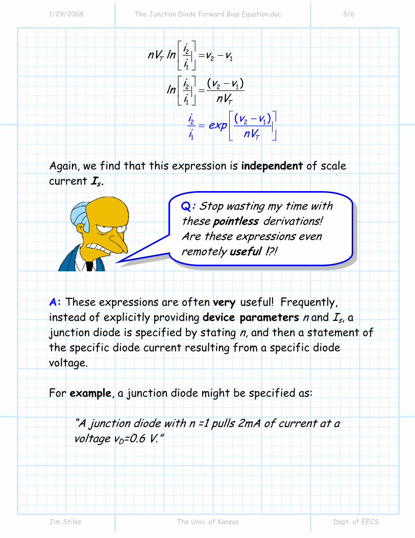
Again, we find that this expression is independent of scale current Is. A: These expressions are often very useful! Frequently, instead of explicitly providing device parameters n and Is, a junction diode is specified by stating n, and then a statement of the specific diode current resulting from a specific diode voltage. For example, a junction diode might be specified as:
“A junction diode with n =1 pulls 2mA of current at a voltage vD=0.6 V.”
Q: Stop wasting my time with these pointless derivations! Are these expressions even remotely useful !?!

1/29/2008 The Junction Diode Forward Bias Equation.doc 4/6
Jim Stiles The Univ. of Kansas Dept. of EECS
The above statement completely specifies the performance of this particular junction diode—we can now determine the current flowing through this diode for any other value of diode voltage vD. Likewise, we can find the voltage across the diode for any other diode current value iD. For example, say we wish to find the current through the junction diode specified above when a potential difference of vD=0.7 V is placed across it. We have two options for finding this current: Option 1: We know that n =1 and that iD =2mA when vD =0.6 V. Thus, we can use this information to solve for scale current Is:
0 60 025
0 60 025
11
2
27 55x10
D
T
vnV
S D.
.S
..
S
S
I e i
I e
I eI . mA
−
−
=
=
=
=
Now, we use the forward-biased junction diode equation to determine the current through this device at the new voltage of vD=0.7 V:
( )0 7
11 0 0257 55x11
009 2
D
T
vnV
SD.
.
i I e
. e. mA
−
=
=
=

1/29/2008 The Junction Diode Forward Bias Equation.doc 5/6
Jim Stiles The Univ. of Kansas Dept. of EECS
Option 2 Here, we directly determine the current at vD = 0.7 using one of the expressions derived earlier in this handout! Using i1 =2 mA and v1 =0.6 we can state the relation ship between current i2 as and voltage v2 as:
2 12 1
2
( )
( 0 6)20 025
T
v vi i expnV
v .exp.
⎡ ⎤−= ⎢ ⎥
⎣ ⎦−⎡ ⎤= ⎢ ⎥⎣ ⎦
For v2 =0.7 V we can therefore find current i2 as:
2
109
(0.7 0
2
6)20 025
.i exp.
. mA
−⎡ ⎤= ⎢ ⎥⎣ ⎦=
Option 2 (using the equations we derived in this handout) is obviously quicker and easier (note in option 2 we did not have to deal with annoying numbers like 7.55 x 10⁻¹¹ !). Finally, we should also note that junction diodes are often specified simply as “ a 2mA diode” or “a 10 mA diode” or “a 100 mA diode”. These statement implicitly provide the diode current at the standard diode test voltage of vD=0.7 V.
1/29/2008 The Junction Diode Forward Bias Equation.doc 6/6
Jim Stiles The Univ. of Kansas Dept. of EECS
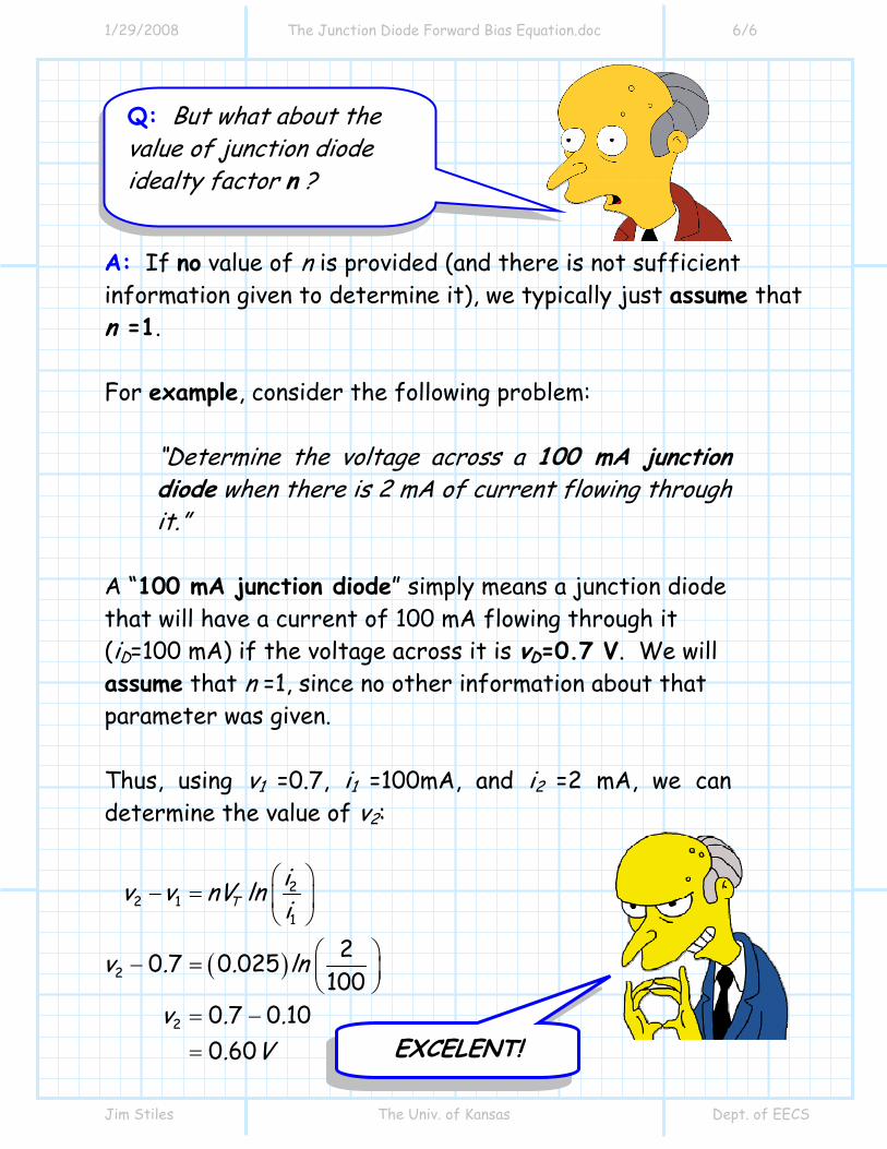
A: If no value of n is provided (and there is not sufficient information given to determine it), we typically just assume that n =1. For example, consider the following problem:
“Determine the voltage across a 100 mA junction diode when there is 2 mA of current flowing through it.”
A “100 mA junction diode” simply means a junction diode that will have a current of 100 mA flowing through it (iD=100 mA) if the voltage across it is vD=0.7 V. We will assume that n =1, since no other information about that parameter was given. Thus, using v1 =0.7, i1 =100mA, and i2 =2 mA, we can determine the value of v2:
( )
22 1
1
2
2
20 7 0 025100
0 7 0 100 60
Tiv v nV lni
v . . ln
v . .. V
⎛ ⎞− = ⎜ ⎟
⎝ ⎠⎛ ⎞− = ⎜ ⎟⎝ ⎠
= −
=
Q: But what about the value of junction diode idealty factor n ?
EXCELENT!

1/29/2008 Example A Junction Diode Circuit.doc 1/3
Jim Stiles The Univ. of Kansas Dept. of EECS
Example: A Junction Diode Circuit
Consider the following circuit with two junction diodes:
The diodes are identical, with n = 1 and IS = 10-14 A. Q: If the current through the resistor is 6.5 mA, what is the
voltage of source VS ?? A: This is a difficult problem to solve ! Certainly, we cannot
just write: =SV
and then the answer. Instead, let’s just determine what we
can, and see what happens !
Di 2 +
−Dv 2
Di 1
+ −Dv 1
+ -
+
−Rv VS
6.5 mA
100 Ω

1/29/2008 Example A Junction Diode Circuit.doc 2/3
Jim Stiles The Univ. of Kansas Dept. of EECS
1) If 6.5 mA flows through a 0.1 K resistor, the voltage across that resistor is:
( )0 1 6 5 0 65R . . . Vv ==
2) If the voltage across the resistor is 0.65 V, then the voltage across the diode D2 , which is parallel to the resistor, is the same value:
2 0 65RD vv . V== 3) If we know the voltage across a p-n junction diode, then we also know its current !
−⎡ ⎤ ⎡ ⎤= = =⎢ ⎥ ⎢ ⎥⎣ ⎦⎣ ⎦D
SDT
v .i I exp exp . mAnV .
1422
0 65010 1 960 025
4) If we know iD2 and the current through the resistor, we know (using KCL) the current through D1 :
1 26 56 5 1 968 46
DD . i. ..
i
mA
+
= +
=
=
Di 2 +
−Dv 2
Di 1
+ −Dv 1
+ -
+
−Rv VS
6.5 mA
100 Ω

1/29/2008 Example A Junction Diode Circuit.doc 3/3
Jim Stiles The Univ. of Kansas Dept. of EECS
5) If we know the current through a junction diode, then we can find the voltage across it:
−
⎛ ⎞ ⎛ ⎞= = =⎜ ⎟ ⎜ ⎟⎝ ⎠⎝ ⎠
DD T
S
i .v nV ln . ln . VI
11 14
0 008460 025 0 6910
6) Finally, if we know vD1 and vD2, we can find VS using KVL:
1 2 0 69 0 65 1 34DS DV v v . . . V+ = + ==
.=Di mA2 1 96
.=
+
−Dv V2 0 65
.=Di 1 8 46mA
=+ −Dv . V1 0 69
+ - .=
+
−Rv V0 65
VS=1.34V 6.5 mA
100 Ω
.=Di mA2 1 96
.+
=
−Dv V2 0 65
.=Di mA1 8 46
+ −Dv 1
+ - .
+
=−Rv V0 65 VS
6.5 mA
100 Ω

1/29/2008 Forward and Reverse Bias Approximations.doc 1/6
Jim Stiles The Univ. of Kansas Dept. of EECS
Forward and Reverse Bias Approximations
A: Actually, all three of the above statements are true (or, at least, approximately so)! Let’s review what we know about the junction diode in forward and revered bias: 1. First, we know that if the diode is not in breakdown, the relationship between current and voltage can be precisely described as:
Q: Man, am I ever befuddled! Is the behavior of a junction diode in the forward biased region described as this:
1D
Tv
nVsDi I e⎛ ⎞
= −⎜ ⎟⎝ ⎠
?
or as this: D
Tv
nVsDi I e= ?
or as this
0 and 0 7 V D Di v .> = ???

1/29/2008 Forward and Reverse Bias Approximations.doc 2/6
Jim Stiles The Univ. of Kansas Dept. of EECS
1 for D
Tv
nVs ZKD Di I e v V⎛ ⎞
= − > −⎜ ⎟⎝ ⎠
A: The above expression is valid for forward bias, and it is valid for reverse bias, and it is also valid for the transition region between forward and reverse bias! In other words, the above equation is a very accurate description of the junction diode behavior—with the important exception of when the junction diode is in breakdown. 2. Now, lets simplify the previous expression further, separately examining the cases when the junction diode is in forward bias (i.e., D Tv nV ), and reverse bias (i.e., ZK D T-V v nV< − ). For the forward bias case, we find that:
1 if D
Tv
nVD Te v nV
Q: Here’s where I get confused. Is this equation valid for reverse bias, or is it valid for forward bias?

1/29/2008 Forward and Reverse Bias Approximations.doc 3/6
Jim Stiles The Univ. of Kansas Dept. of EECS
Therefore, we can approximate the junction diode behavior in forward bias mode as:
for (i.e., forward biased)D
Tv
nVsD D Ti I e v nV≈
Likewise, for the reverse bias case, we find that:
1 if D
Tv
nVD Te v nV−
Therefore, we can approximate the junction diode behavior in reverse bias mode as:
ZKfor -V (i.e., reversed biased)sD D Ti I v nV≈ − < − Combining, we can approximate the expression at the top of the previous page as:
ZK
for (i.e., forward biased)
for -V (i.e., reversed biased)
DT
vnV
s D T
D
s D T
I e v nVi
I v nV
⎧⎪⎪≈ ⎨⎪ − < −⎪⎩
3. We can now simplify these expressions even further! We rewrite the above approximation for forward bias so that the junction diode voltage is a function of junction diode current:

1/29/2008 Forward and Reverse Bias Approximations.doc 4/6
Jim Stiles The Univ. of Kansas Dept. of EECS
D
T
DT
vnV
s Dv
nV D
s
D D
sT
DD T
s
I e iieI
v ilnnV I
iv nV lnI
=
=
⎡ ⎤= ⎢ ⎥
⎣ ⎦⎡ ⎤
= ⎢ ⎥⎣ ⎦
As a previous example demonstrated, as we vary the value of diode current iD from microamps to kiloamps, the diode voltage will vary only a few hundred millivolts, from about 0.5 V to 0.9 V. Thus, we can assume that if any appreciable current is flowing from junction diode anode to junction diode cathode (i.e., forward bias condition), the junction diode voltage will be approximately (i.e., within a few hundred millivolts) 0.7 V.
Q: It looks to me that you are saying a forward biased junction diode exhibits a diode voltage of vD =700mV, regardless of the diode current iD, right?

1/29/2008 Forward and Reverse Bias Approximations.doc 5/6
Jim Stiles The Univ. of Kansas Dept. of EECS
A: NO! This is not what I am saying! As is evident in the previous two equations, the junction diode current in forward bias is directly dependent on diode current—as the current increases, the voltage increases! For each possible diode current, there is a specific (and different) diode voltage.
* However, we find that this increase is logarithmically related to diode current, such that the voltage increases very slowly with increasing current—it takes a bunch of additional junction diode current to increase the junction diode voltage even a small amount.
* Thus, we are simply saying that for all appreciable (and
plausible) diode currents, the junction diode voltage will be within of few hundred millivolts of, say, 700 mV.
* As a result, vD = 0.7 V is not a bad approximation for
forward biased junction diodes! Now, we can likewise simplify further our approximation for a reverse biased junction diode. Recall that we now approximate the reverse bias diode current as sDi I= − . However, recall that the diode saturation current Is is a very small value, typically 10-8 to 10-15 Amps!
Q: A billionth of an amp!? That’s so tiny it might as well be zero!
1/29/2008 Forward and Reverse Bias Approximations.doc 6/6
Jim Stiles The Univ. of Kansas Dept. of EECS
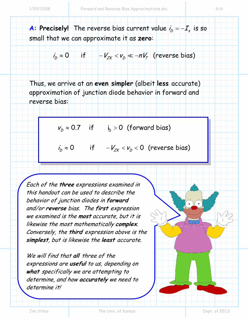
A: Precisely! The reverse bias current value sDi I= − is so small that we can approximate it as zero:
0 if (reverse bias)ZKD D Ti V v nV≈ − < −
Thus, we arrive at an even simpler (albeit less accurate) approximation of junction diode behavior in forward and reverse bias:
D0 7 if i 0 (forward bias)
0 if 0 (reverse bias)
D
ZKD D
v .
i V v
≈ >
≈ − < <
Each of the three expressions examined in this handout can be used to describe the behavior of junction diodes in forward and/or reverse bias. The first expression we examined is the most accurate, but it is likewise the most mathematically complex. Conversely, the third expression above is the simplest, but is likewise the least accurate. We will find that all three of the expressions are useful to us, depending on what specifically we are attempting to determine, and how accurately we need to determine it!